EP2308521B1 - Shape memory surgical fasteners - Google Patents
Shape memory surgical fasteners Download PDFInfo
- Publication number
- EP2308521B1 EP2308521B1 EP10251766.1A EP10251766A EP2308521B1 EP 2308521 B1 EP2308521 B1 EP 2308521B1 EP 10251766 A EP10251766 A EP 10251766A EP 2308521 B1 EP2308521 B1 EP 2308521B1
- Authority
- EP
- European Patent Office
- Prior art keywords
- fastener
- tissue
- lactide
- poly
- base
- Prior art date
- Legal status (The legal status is an assumption and is not a legal conclusion. Google has not performed a legal analysis and makes no representation as to the accuracy of the status listed.)
- Not-in-force
Links
Images


Classifications
-
- A—HUMAN NECESSITIES
- A61—MEDICAL OR VETERINARY SCIENCE; HYGIENE
- A61B—DIAGNOSIS; SURGERY; IDENTIFICATION
- A61B17/00—Surgical instruments, devices or methods, e.g. tourniquets
- A61B17/064—Surgical staples, i.e. penetrating the tissue
- A61B17/0644—Surgical staples, i.e. penetrating the tissue penetrating the tissue, deformable to closed position
-
- A—HUMAN NECESSITIES
- A61—MEDICAL OR VETERINARY SCIENCE; HYGIENE
- A61B—DIAGNOSIS; SURGERY; IDENTIFICATION
- A61B17/00—Surgical instruments, devices or methods, e.g. tourniquets
- A61B17/0057—Implements for plugging an opening in the wall of a hollow or tubular organ, e.g. for sealing a vessel puncture or closing a cardiac septal defect
-
- A—HUMAN NECESSITIES
- A61—MEDICAL OR VETERINARY SCIENCE; HYGIENE
- A61B—DIAGNOSIS; SURGERY; IDENTIFICATION
- A61B17/00—Surgical instruments, devices or methods, e.g. tourniquets
- A61B17/068—Surgical staplers, e.g. containing multiple staples or clamps
-
- A—HUMAN NECESSITIES
- A61—MEDICAL OR VETERINARY SCIENCE; HYGIENE
- A61B—DIAGNOSIS; SURGERY; IDENTIFICATION
- A61B17/00—Surgical instruments, devices or methods, e.g. tourniquets
- A61B17/10—Surgical instruments, devices or methods, e.g. tourniquets for applying or removing wound clamps, e.g. containing only one clamp or staple; Wound clamp magazines
-
- A—HUMAN NECESSITIES
- A61—MEDICAL OR VETERINARY SCIENCE; HYGIENE
- A61L—METHODS OR APPARATUS FOR STERILISING MATERIALS OR OBJECTS IN GENERAL; DISINFECTION, STERILISATION OR DEODORISATION OF AIR; CHEMICAL ASPECTS OF BANDAGES, DRESSINGS, ABSORBENT PADS OR SURGICAL ARTICLES; MATERIALS FOR BANDAGES, DRESSINGS, ABSORBENT PADS OR SURGICAL ARTICLES
- A61L31/00—Materials for other surgical articles, e.g. stents, stent-grafts, shunts, surgical drapes, guide wires, materials for adhesion prevention, occluding devices, surgical gloves, tissue fixation devices
- A61L31/04—Macromolecular materials
- A61L31/041—Mixtures of macromolecular compounds
-
- A—HUMAN NECESSITIES
- A61—MEDICAL OR VETERINARY SCIENCE; HYGIENE
- A61L—METHODS OR APPARATUS FOR STERILISING MATERIALS OR OBJECTS IN GENERAL; DISINFECTION, STERILISATION OR DEODORISATION OF AIR; CHEMICAL ASPECTS OF BANDAGES, DRESSINGS, ABSORBENT PADS OR SURGICAL ARTICLES; MATERIALS FOR BANDAGES, DRESSINGS, ABSORBENT PADS OR SURGICAL ARTICLES
- A61L31/00—Materials for other surgical articles, e.g. stents, stent-grafts, shunts, surgical drapes, guide wires, materials for adhesion prevention, occluding devices, surgical gloves, tissue fixation devices
- A61L31/04—Macromolecular materials
- A61L31/06—Macromolecular materials obtained otherwise than by reactions only involving carbon-to-carbon unsaturated bonds
-
- A—HUMAN NECESSITIES
- A61—MEDICAL OR VETERINARY SCIENCE; HYGIENE
- A61B—DIAGNOSIS; SURGERY; IDENTIFICATION
- A61B17/00—Surgical instruments, devices or methods, e.g. tourniquets
- A61B2017/00004—(bio)absorbable, (bio)resorbable, resorptive
-
- A—HUMAN NECESSITIES
- A61—MEDICAL OR VETERINARY SCIENCE; HYGIENE
- A61B—DIAGNOSIS; SURGERY; IDENTIFICATION
- A61B17/00—Surgical instruments, devices or methods, e.g. tourniquets
- A61B2017/00831—Material properties
- A61B2017/00867—Material properties shape memory effect
-
- A—HUMAN NECESSITIES
- A61—MEDICAL OR VETERINARY SCIENCE; HYGIENE
- A61B—DIAGNOSIS; SURGERY; IDENTIFICATION
- A61B17/00—Surgical instruments, devices or methods, e.g. tourniquets
- A61B17/064—Surgical staples, i.e. penetrating the tissue
- A61B2017/0641—Surgical staples, i.e. penetrating the tissue having at least three legs as part of one single body
-
- A—HUMAN NECESSITIES
- A61—MEDICAL OR VETERINARY SCIENCE; HYGIENE
- A61B—DIAGNOSIS; SURGERY; IDENTIFICATION
- A61B90/00—Instruments, implements or accessories specially adapted for surgery or diagnosis and not covered by any of the groups A61B1/00 - A61B50/00, e.g. for luxation treatment or for protecting wound edges
- A61B90/03—Automatic limiting or abutting means, e.g. for safety
- A61B2090/037—Automatic limiting or abutting means, e.g. for safety with a frangible part, e.g. by reduced diameter
-
- A—HUMAN NECESSITIES
- A61—MEDICAL OR VETERINARY SCIENCE; HYGIENE
- A61L—METHODS OR APPARATUS FOR STERILISING MATERIALS OR OBJECTS IN GENERAL; DISINFECTION, STERILISATION OR DEODORISATION OF AIR; CHEMICAL ASPECTS OF BANDAGES, DRESSINGS, ABSORBENT PADS OR SURGICAL ARTICLES; MATERIALS FOR BANDAGES, DRESSINGS, ABSORBENT PADS OR SURGICAL ARTICLES
- A61L2400/00—Materials characterised by their function or physical properties
- A61L2400/16—Materials with shape-memory or superelastic properties
Definitions
- the present disclosure relates to surgical fasteners. More particularly, the present disclosure relates to a surgical fastener and a method for closing a puncture wound or incision in a patient's tissue.
- an access device includes a housing and a cannula extending from the housing.
- the housing may include valves, seals and other mechanisms for directing an instrument into a body cavity of a patient.
- Cannulas typically are configured to pass through the skin of the patient into the body cavity, i.e., abdomen, either through the use of a bladed tip or through a premade incision.
- the one or more access devices used to access the body cavity of the patient are removed, thus creating one or more puncture wounds or incisions.
- the size of the incision may vary depending on the size of the cannula used to access the body cavity. Certain procedures require a larger passageway into the body cavity in which to complete the procedure. Closing the abdominal side of the incision using conventional methods, i.e. staples or sutures, requires either accessing the incision internally or increasing the dimension of the incision to permit manipulation of a suture or stapling device therethrough. As the body cavity is being accessed through the incision being closed, accessing the incision from within the body typically is not an option.
- a surgical fastener configured to close an opening in tissue is provided as in appended claim 1.
- the surgical fastener includes a base defining a central axis at least one pair of legs extends from the base.
- Each of the legs includes a base portion and a tissue engaging portion.
- each of the tissue engaging portions is arranged to define an insertion direction and when in a second position, each of the tissue engaging portions extends inward towards the central axis.
- the surgical fastener is at least partially formed from a shape memory material including a combination of Polydioxanone and Poly(L-lactide) or a combination of Trimethylene Carbonate and Poly(L-lactide).
- the pair of legs are configured to move from the first position to the second position upon activation of the shape memory material, by the application of heat.
- the shape memory material includes one of 15% Polydioxanone and 85% Poly(L-lactide), 20% Polydioxanone and 80% Poly(L-lactide), 15% Trimethylene Carbonate and 85% Poly(L-lactide) and 20% Trimethylene Carbonate and 80% Poly(L-lactide). It is envisioned that that the shape memory material may include as much as 99% lactide copolymer.
- the fastener may change from the first position to the second position upon the application of heat.
- An insertion member may be integrally formed with the base.
- the tissue engaging portions may include barbs for engaging tissue.
- the base may include one of an opening or a protrusion configured for operable engagement with an insertion instrument.
- a frangible connection may be formed between an insertion member and the base.
- the fastener includes a second pair of legs.
- the apparatus includes an insertion instrument having an elongated shaft and an extension extending from a distal end of the elongated shaft.
- the extension includes a distal end configured for operable engagement with a surgical fastener.
- the extension defines one or more vents through which suction may be provided to draw tissue thereabout.
- the apparatus further includes a fastener as in appended claims 5-7.
- Each of the legs may include an arcuate shape.
- Each leg may include a point defining an insertion direction.
- the method includes the step of providing an insertion instrument including the surgical fastener releasably secured to the distal end thereof.
- the surgical fastener has an open configuration and is closable.
- the method further includes the steps of inserting the distal end of the insertion instrument into the opening, pulling the tissue towards the distal end of the insertion instrument, retracting the insertion instrument proximally through the incision such that legs of the surgical fastener engage tissue, closing the surgical fastener around the tissue, disengaging the insertion instrument from the surgical fastener, and withdrawing the insertion instrument from the incision.
- the method may includes applying a vacuum to the tissue.
- the fastener is closed by activation of the shape memory material.
- the method may further include the step of rotating the fastener about ninety degrees (90°) after inserting the distal end of the insertion instrument into the opening.
- FIG. 1 is a perspective view of an embodiment of a staple according to the present disclosure, in a first or open position;
- FIG. 2 is a perspective view the staple of FIG. 1 , in a second or closed position;
- FIG. 3 is a perspective view of an alternate embodiment of a staple according to the present disclosure, in a first or open position;
- FIG. 4 is a perspective view the staple of FIG. 3 , in a second or closed position
- FIG. 5 is a perspective view of the distal portion of an insertion instrument operably connect to a source of heated fluid and a vacuum source and including the fastener of FIGS. 3 and 4 attached thereto;
- FIG. 6-10 are progressive partial cross-sectional side views of the steps of applying the fastener of FIGS. 3 and 4 ;
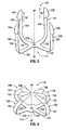
- FIG. 11 is a perspective view of another embodiment of a fastener according to the present disclosure, in a first or open position;
- FIG. 12 is a perspective view the fastener of FIG. 11 , in a second or closed position;
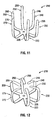
- FIG. 13 is a perspective view of still yet another embodiment of a fastener according to the present disclosure, in a first or open position;
- FIG. 14 is a perspective view the fastener of FIG. 13 , in a second or closed position;
- FIG. 15 is a top view of yet another embodiment of a fastener according to the present disclosure.
- FIG. 16 is a perspective view of an embodiment of a fastener according the present disclosure operably engaged with an alternate embodiment of an insertion instrument.
- proximal refers to that part or component closer to the user or operator, i.e. surgeon or physician
- distal refers to that part or component further away from the user.
- Fastener 10 is composed of a shape memory material that defines a first configuration at a first temperature, i.e., room temperature, and a second configuration at a second temperature, i.e., body temperature.
- Shape memory polymeric materials utilized to form a fastener 10 possess a first phase and a second phase.
- the first phase ( FIG. 1 ) is a configuration which facilitates insertion of fastener 10 into the tissue of a patient body.
- the second phase ( FIG. 2 ), which is assumed upon application of heat, such as body heat, is of a configuration which enhances the retention of fastener 10 in the tissue.
- legs 20 and 30 of fastener 10 possesses an aligned first phase which facilitates insertion into tissue, and a curved second phase configured to engage tissue and close a side of an incision.
- Suitable shape memory polymeric materials some of which may be utilized in a surgical fastener of the present disclosure include, for example, polyurethanes, poly(styrene-butadiene) block copolymers, polynorbornenes, caprolactones, dioxanones, diol esters including oligo (epsilon caprolactone) diol, lactic acid, lactide, glycolic acid, glycolide, ether-ester diols including oligo (p-dioxanone) diol, carbonates including trimethylene carbonate, combinations thereof, and the like.
- the shape memory polymer is be a copolymer of two components with different thermal characteristics.
- Table 1 represents the block copolymers in each system in annealed wire format, the proposed soft and hard segments, and the glass transition temperature (T g ), as measured by differential scanning calorimetery, which is equal to T Trans .
- T g glass transition temperature
- the materials listed include a maximum of 85% lactide copolymer, it is envisioned that the material may include as much as 99% lactide copolymer and still exhibit shape memory characteristics.
- T Trans may be tailored by blending various amounts of low molecular weight oligomers of the soft segment domain material into the parent co-polymer. It is hypothesized that such oligomers would act as plasticizers on the soft domains and cause a downward shift in T Trans .
- T Trans could be easily controlled reproducibly and precisely using a blending method, unlike approaches often described in the literature in which T Trans is controlled by tailoring polymerization reaction parameters.
- trimethylene carbonate (TMC) as a plasticizer may provide the benefit of a self-strengthening device, which becomes stronger and more rigid after being implanted since TMC monomer and low molecular weight TMC oligomers readily diffuse into aqueous environments.
- a molding process may be utilized to produce the fastener 10.
- Plastic molding methods are within the purview of those skilled in the art and include, but are not limited to, melt molding, solution molding and the like. Injection molding, extrusion molding, compression molding and other methods may also be used as the melt molding technique.
- fastener 10 includes a base 12 and a pair of legs 20 and 30 extending from base 12.
- Fastener 10 defines a central axis "X" extending therethrough, which also defines an insertion direction "A" ( FIG. 1 ).
- base 12 includes an opening or detent 13 configured for operable engagement with an insertion instrument.
- fastener 10 includes two (2) legs, however, it is envisioned that fastener 10 may have more or less than two (2) legs, e.g., four legs ( FIG. 3 ) or six legs ( FIG. 11 ).
- Each of legs 20, 30 includes a base portion 22, 32, a connection portion 24, 34 and a tissue engaging portion 26, 36, respectively.
- Base portions 22, 32 may be of equal or different lengths and are configured such that fastener 10 may be inserted through an incision or cannula into a body cavity of a patient.
- Connection portions 24, 34 may be of equal or different lengths and are configured such that when fastener 10 is received in tissue, tissue engaging portions 26, 36 of respective legs 20, 30 do not extend completely through the tissue.
- connection portions 24, 34 are configured such that tissue engaging portions 26, 36 extend completely through the tissue in the first or open position.
- Tissue engaging portions 26, 36 may include an enlarged barbed head, as shown, or may be otherwise suitably configured for piercing and/or engaging tissue.
- tissue engaging portions 26, 36 are tapered, curved, angled, and/or pointed at least slightly in the direction of insertion to facilitate insertion of fastener 10 into tissue.
- fastener 10 in the first phase, includes a first or open position configured for insertion into tissue.
- tissue engaging portions 26, 36 of respective legs 20, 30 are maintained substantially parallel to central axis "X".
- connection portion 24, 34, of respective legs 20, 30 define angles ⁇ 2 , ⁇ 3 , respectively, with respect to base portions 22, 32, respectively.
- angles ⁇ 2 , ⁇ 3 define an angle of ninety degrees (90°).
- Angles ⁇ 2 , ⁇ 3 may each be the same, as shown, or instead, angles ⁇ 2 , ⁇ 3 may be different.
- base portions 22, 32 and connection portions 24, 34 of legs 20, 30, respectively form curved members.
- fastener 10 in the second phase, includes a second or closed position configured for engaging and retaining tissue.
- tissue engaging portions 26, 36 of respective legs 20, 30 extend radially inward.
- tissue engaging portions 26, 36 are maintained substantially perpendicular to the central axis "X".
- tissue engaging portions 26, 36 may extend radially inward and downwards towards base 12.
- Each of base portions 22, 32 and connection portions 24, 34 of respective legs 20, 30 maintain a curved configuration defining an angle ⁇ 2 , ⁇ 3 , respectively, therebetween.
- Angles ⁇ 2 , ⁇ 3 may be the same, as shown, or instead, angles ⁇ 2 , ⁇ 3 may be different.
- legs 20, 30 are substantially parallel to one another, for example, the fastener could have a substantially "H" shaped-configuration. ( FIG. 15 )
- base portions 22, 32 of legs 20, 30 define an angle ⁇ 2 , ⁇ 3 therebetween.
- angles ⁇ 2 , ⁇ 3 define an angle of one-hundred eighty degrees (180°).
- Angles ⁇ 2 , ⁇ 3 may each be the same, as shown, or instead, angles ⁇ 2 , ⁇ 3 may be different.
- fastener 110 is substantially similar to fastener 10 described herein above.
- Fastener 110 includes a base 112 and two pair of legs 120, 130, 140, 150 extending from base 112.
- Fastener 110 defines a central axis "X" extending therethrough, which also defines an insertion direction "A".
- Base 112 includes an opening or detent 113 configured for operable engagement with an insertion instrument.
- Each of legs 120, 130, 140, 150 includes a base portion 122, 132, 142, 152 a connection portion 124, 134, 144, 154 and a tissue engaging portion 126, 136, 146, 156, respectively.
- Base portions 122, 132, 142, 152 may be of equal or different lengths and are configured such that fastener 110 may be inserted through an incision or cannula into a body cavity of a patient.
- Connection portions 124, 134, 144, 154 may be of equal or different lengths and are configured such that when fastener 110 is received in tissue, tissue engaging portions 126, 136, 146, 156 of respective legs 120, 130, 140, 150 do not extend completely through the tissue.
- connection portions 124, 134, 144, 154 are configured such that tissue engaging portions 126, 136, 146, 156 extend completely through the tissue in the first or open position.
- fastener 110 in the first phase, includes a first or open position ( FIG. 3 ) configured for insertion into tissue. In the first or open position, tissue engaging portions 126, 136, 146, 156 of respective legs 120, 130, 140, 150 are maintained parallel to central axis "X".
- fastener 110 in the second phase, includes a second or closed position ( FIG. 4 ) configured for engaging and retaining tissue. In the closed position, tissue engaging portions 126, 136, 146, 156 of respective legs 120, 130, 140, 150 extend radially inward. In one embodiment, tissue engaging portions 126, 136, 146, 156 are maintained perpendicular to the central axis "X". Alternatively, tissue engaging portions 126, 136, 146, 156 may extend radially inward and downwards towards base 112.
- Insertion instrument 60 includes an elongated shaft 62 having a extension 64 operably extending therefrom.
- Extension 64 may be tapered, as shown, or may be cylindrical, substantially planar or otherwise configured for insertion through an incision. Extension 64 may be integrally formed, securely connected or releasably connected with elongated shaft 62. Tapered extension 64 includes a distal end 64b configured for operable engagement with fastener 110.
- distal end 64b of tapered end 64 is integrally formed with fastener 110 and is configured to break-way from fastener 110 at a predetermined time, i.e., upon deformation of fastener 110 from the open position to the closed position.
- fastener 110 includes an opening 113 ( FIG. 3 ) through which fastener 110 is selectively engaged by insertion instrument 60. In this manner, fastener 110 is released from insertion instrument 60 through action of the user. It is contemplated that the point of attachment between fastener 110 and distal end 64b may be a frangible connection.
- tapered extension 64 includes one or more vents 65. Vents 65 are operably connected to a source of suction 70. As will be discussed in further detail below, suction is provided through vents 65 from suction source 70 to cause opposed sides of incision "I" ( FIG. 6 ) to be drawn about tapered extension 64. Tapered extension 64 may further include an opening 67 formed near distal end 64b operably connected to a source of heated fluid 80. As will also be discussed in further detail below, ejection of a heated fluid (not shown) through opening 67 in tapered extension 64 bathes fastener 110 in the heated fluid, thereby causing fastener 110 to deform from the open position to the closed position.
- fastener 110 includes a hollow configuration through which the heated fluid flows to cause the deformation of fastener 110.
- fastener 110 may include a conductive core capable of heating fastener 110. In this manner, heated fluid source 80 is replaced by a source of electrical energy, and electrical energy is provided to the conductive core to heat fastener 110, thereby causing deformation of fastener 110 from the first position to the second position.
- fastener 110 may be configured to deform upon application of infrared light, chemical agents, heat or other suitable activating agent.
- fastener 110 is operably received on distal end 64b of tapered extension 64 of insertion instrument 60.
- fastener 110 may be integrally formed with tapered extension 64, or otherwise mechanically secured thereto.
- insertion instrument 60 it should be appreciated that other instruments and/or methods may be used to apply fastener 110.
- insertion instrument 60 may be used to apply other fasteners, i.e., fastener 10.
- Fastener 110 is configured to be received through a cannula or sleeve “S” inserted through an incision “I” in tissue "T” of a patient, as indicated by arrow “A".
- fastener 110 and instrument 60 are inserted into a body cavity independently of one another and are subsequently secured together within the body cavity.
- sleeve “S” is removed from tissue “T", as indicated by arrow “B”.
- tissue “T” collapses about elongated shaft 62 and tapered extension 64 ( FIG. 7 ).
- Tissue “T” is further drawn about tapered extension 64 by suction provided from suction source 70 ( FIG. 5 ) through openings 65 formed in tapered extension 64.
- tissue "T” has been drawn about tapered extension 64 of insertion instrument 60
- insertion instrument 60 is pulled proximally through tissue “T", as indicated by arrow “C”, thereby causing tissue engaging portions 126, 136, 146, 156 of fastener 110 to be received within tissue “T” about incision “I”.
- tissue engaging portions 126, 136, 146, 156 With tissue "T"
- the heat provided by tissue "T” may cause fastener 110 to deform from the open position to the closed position.
- tissue “T” may be temporarily heated above normal body temperature to cause the deformation of fastener 110. In this manner, tissue “T” is heated to Tg (above body temperature) to cause fastener 110 to deform. Since polymers become softer and more flexible above Tg, by having Tg above body temperature, once the tissue "T” cools to body temperature, fastener 110 will be stiffer and stronger.
- a heated fluid may be provided through opening 67 in extension 64 to bathe fastener 110 in the heated fluid, thereby causing fastener 110 to deform or the heated fluid may be directed into and/or through hollow portions (not shown) of fastener 110 to cause the deformation thereof, or a source of electrical energy may be activated to supply a heat inducing core (not shown) within fastener 110 with energy to cause the heating thereof, and thus, deformation of fastener 110.
- tapered extension 64 of insertion instrument 60 is separated from fastener 110 prior to or during the deformation of fastener 110 from the open position to the closed position.
- tapered extension 64 may be connected to fastener 110 by a break-away connection that breaks during deformation of fastener 110.
- insertion instrument 60 includes a release mechanism (not shown) for releasing fastener 110 therefrom. Upon release of fastener 110 from tapered extension 64, insertion instrument 60 is completely removed from incision "I".
- fastener 110 securely engages tissue "T" about an internal or abdominal side of incision “I” thereby closing incision "I".
- An outer side of incision “I” may be closed in a conventional manner.
- the insertion instrument can be configured to dispense a wound closure material, such as by including a passage for wound closure material to be carried to a dispersing aperture.
- the wound closure materials in U.S. Patent Nos. 7,717,313 and 7,455,682 can be used.
- fastener 110 may instead be configured to extend completely through tissue "T", in which case, external closure of incision "I” may not be necessary.
- One or more additional fasteners 110 may be applied to tissue "T” in the manner described above.
- Fastener 210 is substantially similar to fasteners 10, 110 described hereinabove, and therefore, will only be described as relates to the differences therebetween.
- Fastener 210 includes six legs 220, 230, 240, 250, 260, 270 for more securely closing an incision formed in tissue.
- Tissue engaging portions 226, 236, 246, 256, 266, 276 of legs 220, 230, 240, 250, 260, 270, respectively, are tapered or pointed to facilitate insertion into tissue.
- fastener 310 is substantially similar to fasteners 10, 110, 210 described hereinabove.
- Fastener 310 includes a first pair of legs 320 and a second pair of legs 340.
- Each of first and second pairs of legs 320, 340 are of a different lengths.
- each pair of legs 320, 340 assumes a different configuration in the closed position ( FIG. 14 ). In this manner, fastener 310 is configured to more securely engage tissue.
- fastener 10 may be formed of a material that causes legs 120, 130 to be in a closed first position and when cooled below a predetermined temperature assumes an open second position. In this manner, fastener 110 is inserted within tissue "T" when in the cooled second position, and upon engagement with heated body "T", fastener 110 returns to the closed first position.
- fastener 10 is configured to be pushed into tissue from the outside to close the skin, muscle layer, etc. ( FIG. 16 )
Description
- The present disclosure relates to surgical fasteners. More particularly, the present disclosure relates to a surgical fastener and a method for closing a puncture wound or incision in a patient's tissue.
- Surgical access devices, including trocars and port assemblies, are known, as are myriad of procedures that may be performed through these devices. Typically, an access device includes a housing and a cannula extending from the housing. The housing may include valves, seals and other mechanisms for directing an instrument into a body cavity of a patient. Cannulas typically are configured to pass through the skin of the patient into the body cavity, i.e., abdomen, either through the use of a bladed tip or through a premade incision.
- Upon completion of a procedure, the one or more access devices used to access the body cavity of the patient are removed, thus creating one or more puncture wounds or incisions. The size of the incision may vary depending on the size of the cannula used to access the body cavity. Certain procedures require a larger passageway into the body cavity in which to complete the procedure. Closing the abdominal side of the incision using conventional methods, i.e. staples or sutures, requires either accessing the incision internally or increasing the dimension of the incision to permit manipulation of a suture or stapling device therethrough. As the body cavity is being accessed through the incision being closed, accessing the incision from within the body typically is not an option.
- Therefore, it would be beneficial to have a fastener and fastener inserting instrument configured for closing the body cavity side of an opening.
- The two part form of appended claim 1 is based on the disclosure of
EP 1878391 . - Accordingly, a surgical fastener configured to close an opening in tissue is provided as in appended claim 1. The surgical fastener includes a base defining a central axis at least one pair of legs extends from the base. Each of the legs includes a base portion and a tissue engaging portion. When the fastener is in a first position, each of the tissue engaging portions is arranged to define an insertion direction and when in a second position, each of the tissue engaging portions extends inward towards the central axis. The surgical fastener is at least partially formed from a shape memory material including a combination of Polydioxanone and Poly(L-lactide) or a combination of Trimethylene Carbonate and Poly(L-lactide). The pair of legs are configured to move from the first position to the second position upon activation of the shape memory material, by the application of heat.
- In one embodiment, the shape memory material includes one of 15% Polydioxanone and 85% Poly(L-lactide), 20% Polydioxanone and 80% Poly(L-lactide), 15% Trimethylene Carbonate and 85% Poly(L-lactide) and 20% Trimethylene Carbonate and 80% Poly(L-lactide). It is envisioned that that the shape memory material may include as much as 99% lactide copolymer. The fastener may change from the first position to the second position upon the application of heat. An insertion member may be integrally formed with the base. The tissue engaging portions may include barbs for engaging tissue. The base may include one of an opening or a protrusion configured for operable engagement with an insertion instrument. A frangible connection may be formed between an insertion member and the base. In one embodiment, the fastener includes a second pair of legs.
- Also provided is a wound closure apparatus. The apparatus includes an insertion instrument having an elongated shaft and an extension extending from a distal end of the elongated shaft. The extension includes a distal end configured for operable engagement with a surgical fastener. The extension defines one or more vents through which suction may be provided to draw tissue thereabout. The apparatus further includes a fastener as in appended claims 5-7. Each of the legs may include an arcuate shape. Each leg may include a point defining an insertion direction.
- Additionally provided is a method of inserting the claimed surgical fastener to close an opening in tissue. The method includes the step of providing an insertion instrument including the surgical fastener releasably secured to the distal end thereof. The surgical fastener has an open configuration and is closable. The method further includes the steps of inserting the distal end of the insertion instrument into the opening, pulling the tissue towards the distal end of the insertion instrument, retracting the insertion instrument proximally through the incision such that legs of the surgical fastener engage tissue, closing the surgical fastener around the tissue, disengaging the insertion instrument from the surgical fastener, and withdrawing the insertion instrument from the incision.
- The method may includes applying a vacuum to the tissue. The fastener is closed by activation of the shape memory material. The method may further include the step of rotating the fastener about ninety degrees (90°) after inserting the distal end of the insertion instrument into the opening.
- The accompanying drawings, which are incorporated in and constitute a part of this specification, illustrate embodiments of the disclosure and, together with a general description of the disclosure given above, and the detailed description of the embodiment(s) given below, serve to explain the principles of the disclosure, wherein:
-
FIG. 1 is a perspective view of an embodiment of a staple according to the present disclosure, in a first or open position; -
FIG. 2 is a perspective view the staple ofFIG. 1 , in a second or closed position; -
FIG. 3 is a perspective view of an alternate embodiment of a staple according to the present disclosure, in a first or open position; -
FIG. 4 is a perspective view the staple ofFIG. 3 , in a second or closed position; -
FIG. 5 is a perspective view of the distal portion of an insertion instrument operably connect to a source of heated fluid and a vacuum source and including the fastener ofFIGS. 3 and 4 attached thereto; -
FIG. 6-10 are progressive partial cross-sectional side views of the steps of applying the fastener ofFIGS. 3 and 4 ; -
FIG. 11 is a perspective view of another embodiment of a fastener according to the present disclosure, in a first or open position; -
FIG. 12 is a perspective view the fastener ofFIG. 11 , in a second or closed position; -
FIG. 13 is a perspective view of still yet another embodiment of a fastener according to the present disclosure, in a first or open position; and -
FIG. 14 is a perspective view the fastener ofFIG. 13 , in a second or closed position; -
FIG. 15 is a top view of yet another embodiment of a fastener according to the present disclosure; and -
FIG. 16 is a perspective view of an embodiment of a fastener according the present disclosure operably engaged with an alternate embodiment of an insertion instrument. - Embodiments of the presently disclosed fastener will now be described in detail with reference to the drawings wherein like numerals designate identical or corresponding elements in each of the several views. As is common in the art, the term "proximal" refers to that part or component closer to the user or operator, i.e. surgeon or physician, while the term "distal" refers to that part or component further away from the user. Although the embodiments of the present disclosure will be described for use in closing an incision through tissue into a body cavity, the presently disclosed fasteners and fastener insertion instruments may be modified for use in closing openings in tissue other than incisions, i.e., lacerations, punctures, or in other areas of the body.
- With reference initially to
FIGS. 1 and 2 , a shape memory fastener according to an embodiment of the present disclosure is shown generally asfastener 10.Fastener 10 is composed of a shape memory material that defines a first configuration at a first temperature, i.e., room temperature, and a second configuration at a second temperature, i.e., body temperature. - Shape memory polymeric materials utilized to form a
fastener 10 possess a first phase and a second phase. The first phase (FIG. 1 ) is a configuration which facilitates insertion offastener 10 into the tissue of a patient body. The second phase (FIG. 2 ), which is assumed upon application of heat, such as body heat, is of a configuration which enhances the retention offastener 10 in the tissue. As will be discussed in further detail below,legs fastener 10 possesses an aligned first phase which facilitates insertion into tissue, and a curved second phase configured to engage tissue and close a side of an incision. - Suitable shape memory polymeric materials some of which may be utilized in a surgical fastener of the present disclosure include, for example, polyurethanes, poly(styrene-butadiene) block copolymers, polynorbornenes, caprolactones, dioxanones, diol esters including oligo (epsilon caprolactone) diol, lactic acid, lactide, glycolic acid, glycolide, ether-ester diols including oligo (p-dioxanone) diol, carbonates including trimethylene carbonate, combinations thereof, and the like. In the present invention, the shape memory polymer is be a copolymer of two components with different thermal characteristics.
- Several compositions described in
U.S. Patent No. 5,324,307 have been found to demonstrate shape memory effects. Table 1 represents the block copolymers in each system in annealed wire format, the proposed soft and hard segments, and the glass transition temperature (Tg), as measured by differential scanning calorimetery, which is equal to TTrans. Although the materials listed include a maximum of 85% lactide copolymer, it is envisioned that the material may include as much as 99% lactide copolymer and still exhibit shape memory characteristics.Table 1. SMPs with Proposed Soft and Hard Domains Polymer Tg(TTrans) Designation Composition [mol%] Soft Domain Hard Domain [°C] 15P85L 15% Polydioxanone Polydioxanone and Crystalline Polylactide 54 85% Poly(L-lactide) Amorphous Polylactide 20P80L 20% Polydioxanone Polydioxanone and Crystalline Polylactide 45 80% Poly(L-lactide) Amorphous Polylactide 15T85L 15% Trimethylene Carbonate Trimethylene Carbonate Crystalline Polylactide 54 85% Poly(L-lactide) and Amorphous Polylactide 20T80L 200% Trimethylene Carbonate Trimethylene Carbonate Crystalline Polylactide 55 80% Poly(L-lactide) and Amorphous Polylactide - Preliminary data presented below suggest that the polymer systems in Table 1 undergo a partial shape shift when approaching Tg and that TTrans is depressed when the materials are in aqueous solution. Since it is known that these polymers degrade by water absorption and bulk hydrolysis, it is proposed that water molecules entering the polymer matrices act as plasticizer, causing the soft segments to soften at lower temperatures than in dry air. Polymers exhibiting TTrans depression in aqueous solution would be especially beneficial as implant devices since it should be feasible to maintain the device secondary shape through temperature excursions in the dry state during shipping and storage and still allow shifting at body temperature upon implantation.
- Various synthesis and processing methods may be used to tailor TTrans including changes in block segment molar ratios, polymer molecular weight, and time allowed for hard segment formation. TTrans may also be tailored by blending various amounts of low molecular weight oligomers of the soft segment domain material into the parent co-polymer. It is hypothesized that such oligomers would act as plasticizers on the soft domains and cause a downward shift in TTrans. TTrans could be easily controlled reproducibly and precisely using a blending method, unlike approaches often described in the literature in which TTrans is controlled by tailoring polymerization reaction parameters. Additionally, the use of trimethylene carbonate (TMC) as a plasticizer may provide the benefit of a self-strengthening device, which becomes stronger and more rigid after being implanted since TMC monomer and low molecular weight TMC oligomers readily diffuse into aqueous environments.
- In some embodiments, a molding process may be utilized to produce the
fastener 10. Plastic molding methods are within the purview of those skilled in the art and include, but are not limited to, melt molding, solution molding and the like. Injection molding, extrusion molding, compression molding and other methods may also be used as the melt molding technique. - With reference still to
FIGS. 1 and 2 ,fastener 10 includes abase 12 and a pair oflegs base 12.Fastener 10 defines a central axis "X" extending therethrough, which also defines an insertion direction "A" (FIG. 1 ). As will be discussed in further detail below,base 12 includes an opening ordetent 13 configured for operable engagement with an insertion instrument. As shown inFIG. 1 ,fastener 10 includes two (2) legs, however, it is envisioned thatfastener 10 may have more or less than two (2) legs, e.g., four legs (FIG. 3 ) or six legs (FIG. 11 ). Each oflegs base portion connection portion tissue engaging portion Base portions fastener 10 may be inserted through an incision or cannula into a body cavity of a patient.Connection portions fastener 10 is received in tissue,tissue engaging portions respective legs connection portions tissue engaging portions Tissue engaging portions tissue engaging portions fastener 10 into tissue. - With reference to
FIG. 1 , in the first phase,fastener 10 includes a first or open position configured for insertion into tissue. In the first or open position,tissue engaging portions respective legs connection portion respective legs base portions base portions connection portions legs - Turning now to
FIG. 2 , in the second phase,fastener 10 includes a second or closed position configured for engaging and retaining tissue. In the closed position,tissue engaging portions respective legs tissue engaging portions tissue engaging portions base 12. Each ofbase portions connection portions respective legs legs FIG. 15 ) - With reference to
FIGS. 1 and 2 , in either the first or second phases,base portions legs - With reference now to
FIGS. 3 and 4 ,fastener 110 is substantially similar tofastener 10 described herein above.Fastener 110 includes abase 112 and two pair oflegs base 112.Fastener 110 defines a central axis "X" extending therethrough, which also defines an insertion direction "A".Base 112 includes an opening ordetent 113 configured for operable engagement with an insertion instrument. Each oflegs base portion connection portion tissue engaging portion Base portions fastener 110 may be inserted through an incision or cannula into a body cavity of a patient.Connection portions fastener 110 is received in tissue,tissue engaging portions respective legs connection portions tissue engaging portions - As discussed above with respect to
fastener 10, in the first phase,fastener 110 includes a first or open position (FIG. 3 ) configured for insertion into tissue. In the first or open position,tissue engaging portions respective legs fastener 110 includes a second or closed position (FIG. 4 ) configured for engaging and retaining tissue. In the closed position,tissue engaging portions respective legs tissue engaging portions tissue engaging portions base 112. - Turning now to
FIG. 5 ,fastener 110 is shown operably connected to aninsertion instrument 60.Insertion instrument 60 includes anelongated shaft 62 having aextension 64 operably extending therefrom.Extension 64 may be tapered, as shown, or may be cylindrical, substantially planar or otherwise configured for insertion through an incision.Extension 64 may be integrally formed, securely connected or releasably connected withelongated shaft 62.Tapered extension 64 includes adistal end 64b configured for operable engagement withfastener 110. As shown,distal end 64b of taperedend 64 is integrally formed withfastener 110 and is configured to break-way fromfastener 110 at a predetermined time, i.e., upon deformation offastener 110 from the open position to the closed position. Alternatively,fastener 110 includes an opening 113 (FIG. 3 ) through whichfastener 110 is selectively engaged byinsertion instrument 60. In this manner,fastener 110 is released frominsertion instrument 60 through action of the user. It is contemplated that the point of attachment betweenfastener 110 anddistal end 64b may be a frangible connection. - Still referring to
FIG. 5 , taperedextension 64 includes one or more vents 65.Vents 65 are operably connected to a source ofsuction 70. As will be discussed in further detail below, suction is provided throughvents 65 fromsuction source 70 to cause opposed sides of incision "I" (FIG. 6 ) to be drawn about taperedextension 64.Tapered extension 64 may further include anopening 67 formed neardistal end 64b operably connected to a source ofheated fluid 80. As will also be discussed in further detail below, ejection of a heated fluid (not shown) throughopening 67 in taperedextension 64 bathesfastener 110 in the heated fluid, thereby causingfastener 110 to deform from the open position to the closed position. In an alternative embodiment,fastener 110 includes a hollow configuration through which the heated fluid flows to cause the deformation offastener 110. In yet another embodiment,fastener 110 may include a conductive core capable ofheating fastener 110. In this manner, heatedfluid source 80 is replaced by a source of electrical energy, and electrical energy is provided to the conductive core to heatfastener 110, thereby causing deformation offastener 110 from the first position to the second position. Alternatively,fastener 110 may be configured to deform upon application of infrared light, chemical agents, heat or other suitable activating agent. - With reference now to
FIGS. 6-10 , a method of closing an incision "I" usingfastener 110 will be described in detail. Although shown with reference to an incision created for receipt of an access assembly, the aspects of the present disclosure may be adapted to close most incisions into a body cavity. Referring initially toFIG. 6 ,fastener 110 is operably received ondistal end 64b of taperedextension 64 ofinsertion instrument 60. As discussed above,fastener 110 may be integrally formed with taperedextension 64, or otherwise mechanically secured thereto. Although shown being applied usinginsertion instrument 60, it should be appreciated that other instruments and/or methods may be used to applyfastener 110. Additionally,insertion instrument 60 may be used to apply other fasteners, i.e.,fastener 10.Fastener 110 is configured to be received through a cannula or sleeve "S" inserted through an incision "I" in tissue "T" of a patient, as indicated by arrow "A". In an alternate method,fastener 110 andinstrument 60 are inserted into a body cavity independently of one another and are subsequently secured together within the body cavity. Oncefastener 110 has been inserted through sleeve "S" and received within the body cavity of the patient (FIG. 6 ), sleeve "S" is removed from tissue "T", as indicated by arrow "B". In this manner, tissue "T" collapses aboutelongated shaft 62 and tapered extension 64 (FIG. 7 ). Tissue "T" is further drawn about taperedextension 64 by suction provided from suction source 70 (FIG. 5 ) throughopenings 65 formed in taperedextension 64. - Turning now to
FIG. 8 , once tissue "T" has been drawn about taperedextension 64 ofinsertion instrument 60,insertion instrument 60 is pulled proximally through tissue "T", as indicated by arrow "C", thereby causingtissue engaging portions fastener 110 to be received within tissue "T" about incision "I". Continued retraction ofinsertion instrument 60 causes further engagement oftissue engaging portions legs fastener 110 have fully engaged tissue "T", the heat provided by tissue "T" may causefastener 110 to deform from the open position to the closed position. Alternative, tissue "T" may be temporarily heated above normal body temperature to cause the deformation offastener 110. In this manner, tissue "T" is heated to Tg (above body temperature) to causefastener 110 to deform. Since polymers become softer and more flexible above Tg, by having Tg above body temperature, once the tissue "T" cools to body temperature,fastener 110 will be stiffer and stronger. Alternatively, a heated fluid may be provided throughopening 67 inextension 64 to bathefastener 110 in the heated fluid, thereby causingfastener 110 to deform or the heated fluid may be directed into and/or through hollow portions (not shown) offastener 110 to cause the deformation thereof, or a source of electrical energy may be activated to supply a heat inducing core (not shown) withinfastener 110 with energy to cause the heating thereof, and thus, deformation offastener 110. - With reference to
FIG. 9 , prior to or during the deformation offastener 110 from the open position to the closed position, taperedextension 64 ofinsertion instrument 60 is separated fromfastener 110. As discussed above, taperedextension 64 may be connected tofastener 110 by a break-away connection that breaks during deformation offastener 110. Alternatively,insertion instrument 60 includes a release mechanism (not shown) for releasingfastener 110 therefrom. Upon release offastener 110 from taperedextension 64,insertion instrument 60 is completely removed from incision "I". - Turning now to
FIG. 10 , in the closed position,fastener 110 securely engages tissue "T" about an internal or abdominal side of incision "I" thereby closing incision "I". An outer side of incision "I" may be closed in a conventional manner. Alternatively, the insertion instrument can be configured to dispense a wound closure material, such as by including a passage for wound closure material to be carried to a dispersing aperture. The wound closure materials inU.S. Patent Nos. 7,717,313 and7,455,682 can be used. As discussed above,fastener 110 may instead be configured to extend completely through tissue "T", in which case, external closure of incision "I" may not be necessary. One or moreadditional fasteners 110 may be applied to tissue "T" in the manner described above. - Turning to
FIGS. 11 and 12 , an alternate embodiment of a shape memory fastener according to the present disclosure is shown generally asfastener 210.Fastener 210 is substantially similar tofasteners Fastener 210 includes sixlegs Tissue engaging portions legs - With reference to
FIGS. 13 and 14 , yet another embodiment of a shape memory fastener according to the present disclosure is shown generally asfastener 310.Fastener 310 is substantially similar tofasteners Fastener 310 includes a first pair oflegs 320 and a second pair oflegs 340. Each of first and second pairs oflegs legs FIG. 14 ). In this manner,fastener 310 is configured to more securely engage tissue.
Although the illustrative embodiments of the present disclosure have been described herein with reference to the accompanying drawings, it is to be understood that the disclosure is not limited to those precise embodiments, and that various other changes and modifications may be effected therein by one skilled in the art without departing from the scope of the claims. For example,fastener 10 may be formed of a material that causeslegs fastener 110 is inserted within tissue "T" when in the cooled second position, and upon engagement with heated body "T",fastener 110 returns to the closed first position. In another embodiment,fastener 10 is configured to be pushed into tissue from the outside to close the skin, muscle layer, etc. (FIG. 16 )
Claims (10)
- A surgical fastener (10) comprising:a base (12) defining a central axis;at least one pair of legs (20, 30) extending from the base, each of the legs including a base portion (22, 32) and a tissue engaging portion (26, 36), wherein in a first position each of the tissue engaging portions are arranged to define an insertion direction and in a second position each of the tissue engaging portions extend inward towards the central axis, the surgical fastener being at least partially formed from a shape memory material wherein the fastener is configured to move from the first position to the second position upon activation of the shape memory by the application of heat,characterized in that the shape memory material includes a combination of Polydioxanone and Poly(L-lactide) or a combination of Trimethylene Carbonate and Poly(L-lactide).
- The fastener of claim 1, wherein the shape memory material composed of 15% Polydioxanone and 85% Poly(L-lactide); 20% Polydioxanone and 80% Poly(L-lactide); 15% Trimethylene Carbonate and 85% Poly(L-lactide); or 20% Trimethylene Carbonate and 80% Poly(L-lactide).
- The fastener of claim 1 or 2, wherein the tissue engaging portions include barbs for engaging tissue.
- The fastener of any preceding claim, further including a second pair of legs (120, 130, 140, 150).
- The fastener of any preceding claim, wherein the base includes one of an opening (13), or a protrusion configured for operable engagement with an insertion instrument (60).
- The fastener of any of claims 1 to 4, wherein an insertion member (60) is integrally formed with the base.
- The fastener of claim 6, wherein a frangible connection is formed between the insertion member and the base.
- A wound closure apparatus, comprising:an insertion instrument (60) comprising:an elongated shaft (62); andan extension (64) extending from a distal end of the elongated shaft, the extension including a distal end (64b) configured for operable engagement with a fastener, wherein the extension defines one or more vents (65) through which suction may be provided to draw tissue thereabout; anda fastener according to claim 5.
- The wound closure apparatus of claim 8, wherein the extension further comprises an opening (67) operably connected to a source (80) of heated fluid
- The wound closure apparatus of claim 8, wherein the fastener comprises a conductive core, and the extension is connected to a source of electrical energy configured to provide electrical energy to the conductive core of the fastener.
Applications Claiming Priority (2)
| Application Number | Priority Date | Filing Date | Title |
|---|---|---|---|
| US24964209P | 2009-10-08 | 2009-10-08 | |
| US12/895,966 US9295463B2 (en) | 2009-10-08 | 2010-10-01 | Shape memory fasteners and method of use |
Publications (2)
| Publication Number | Publication Date |
|---|---|
| EP2308521A1 EP2308521A1 (en) | 2011-04-13 |
| EP2308521B1 true EP2308521B1 (en) | 2014-08-27 |
Family
ID=43127693
Family Applications (1)
| Application Number | Title | Priority Date | Filing Date |
|---|---|---|---|
| EP10251766.1A Not-in-force EP2308521B1 (en) | 2009-10-08 | 2010-10-07 | Shape memory surgical fasteners |
Country Status (6)
| Country | Link |
|---|---|
| US (2) | US9295463B2 (en) |
| EP (1) | EP2308521B1 (en) |
| JP (2) | JP2011078790A (en) |
| AU (1) | AU2010227042A1 (en) |
| CA (1) | CA2716708A1 (en) |
| ES (1) | ES2506145T3 (en) |
Cited By (1)
| Publication number | Priority date | Publication date | Assignee | Title |
|---|---|---|---|---|
| US9345478B2 (en) | 2007-09-06 | 2016-05-24 | Cardica, Inc. | Method for surgical stapling |
Families Citing this family (55)
| Publication number | Priority date | Publication date | Assignee | Title |
|---|---|---|---|---|
| US7988026B2 (en) | 2007-09-06 | 2011-08-02 | Cardica, Inc. | Endocutter with staple feed |
| US9295463B2 (en) | 2009-10-08 | 2016-03-29 | Covidien Lp | Shape memory fasteners and method of use |
| EP3508641B1 (en) | 2010-06-17 | 2020-08-05 | Washington University | Biomedical patches with aligned fibers |
| US8360296B2 (en) | 2010-09-09 | 2013-01-29 | Ethicon Endo-Surgery, Inc. | Surgical stapling head assembly with firing lockout for a surgical stapler |
| AU2012222088A1 (en) | 2011-02-25 | 2013-09-12 | Thoratec Corporation | Coupling system, applicator tool, attachment ring and method for connecting a conduit to biological tissue |
| US9033204B2 (en) | 2011-03-14 | 2015-05-19 | Ethicon Endo-Surgery, Inc. | Circular stapling devices with tissue-puncturing anvil features |
| WO2013073609A1 (en) * | 2011-11-15 | 2013-05-23 | Suzuki Naoki | Surgical instrument |
| WO2013151820A1 (en) * | 2012-04-02 | 2013-10-10 | Cardica, Inc. | Surgical stapler with superelastic staples |
| US11547396B2 (en) * | 2012-08-10 | 2023-01-10 | W. L. Gore & Associates, Inc. | Devices and methods for securing medical devices within an anatomy |
| EP3824853B1 (en) | 2012-09-21 | 2023-07-26 | Washington University | Biomedical patches with spatially arranged fibers |
| US9573260B2 (en) * | 2013-05-08 | 2017-02-21 | Arthur R. Walters, JR. | Fastening device for driving double-headed fasteners |
| US20150173756A1 (en) | 2013-12-23 | 2015-06-25 | Ethicon Endo-Surgery, Inc. | Surgical cutting and stapling methods |
| US9724092B2 (en) | 2013-12-23 | 2017-08-08 | Ethicon Llc | Modular surgical instruments |
| US9839428B2 (en) | 2013-12-23 | 2017-12-12 | Ethicon Llc | Surgical cutting and stapling instruments with independent jaw control features |
| USD768297S1 (en) | 2014-10-13 | 2016-10-04 | Ethicon, Inc. | Multi-barbed anchor |
| USD780311S1 (en) * | 2014-11-20 | 2017-02-28 | Biomedical Enterprises, Inc. | Orthopedic implant |
| US10368860B2 (en) | 2014-11-21 | 2019-08-06 | Ethicon, Inc. | Absorbable surgical fasteners for securing prosthetic devices to tissue |
| US11103248B2 (en) | 2015-08-26 | 2021-08-31 | Cilag Gmbh International | Surgical staples for minimizing staple roll |
| MX2022009705A (en) | 2015-08-26 | 2022-11-07 | Ethicon Llc | Surgical staples comprising hardness variations for improved fastening of tissue. |
| CN108348233B (en) | 2015-08-26 | 2021-05-07 | 伊西康有限责任公司 | Surgical staple strip for allowing changing staple characteristics and achieving easy cartridge loading |
| US10314587B2 (en) | 2015-09-02 | 2019-06-11 | Ethicon Llc | Surgical staple cartridge with improved staple driver configurations |
| MX2022006191A (en) | 2015-09-02 | 2022-06-16 | Ethicon Llc | Surgical staple configurations with camming surfaces located between portions supporting surgical staples. |
| EP3355803A4 (en) | 2015-09-28 | 2019-06-12 | M-V Arterica AB | Vascular closure device |
| USD777329S1 (en) * | 2015-10-19 | 2017-01-24 | Nextremity Solutions, Inc. | Bone staple |
| USD773666S1 (en) * | 2015-10-27 | 2016-12-06 | Biomedical Enterprises, Inc. | Orthopedic implant |
| USD773665S1 (en) * | 2015-10-27 | 2016-12-06 | Biomedical Enterprises, Inc. | Orthopedic implant |
| US10772632B2 (en) * | 2015-10-28 | 2020-09-15 | Covidien Lp | Surgical stapling device with triple leg staples |
| US10307159B2 (en) | 2016-04-01 | 2019-06-04 | Ethicon Llc | Surgical instrument handle assembly with reconfigurable grip portion |
| BR112018070100A2 (en) * | 2016-04-01 | 2019-02-05 | Ethicon Llc | surgical stapling system configured to apply annular rows of staples that have different heights |
| US11045191B2 (en) | 2016-04-01 | 2021-06-29 | Cilag Gmbh International | Method for operating a surgical stapling system |
| US11284890B2 (en) | 2016-04-01 | 2022-03-29 | Cilag Gmbh International | Circular stapling system comprising an incisable tissue support |
| US10485542B2 (en) | 2016-04-01 | 2019-11-26 | Ethicon Llc | Surgical stapling instrument comprising multiple lockouts |
| BR112018073290B1 (en) * | 2016-05-12 | 2022-03-03 | Acera Surgical, Inc. | Resorbable non-woven graft material |
| US10632228B2 (en) | 2016-05-12 | 2020-04-28 | Acera Surgical, Inc. | Tissue substitute materials and methods for tissue repair |
| US10542979B2 (en) | 2016-06-24 | 2020-01-28 | Ethicon Llc | Stamped staples and staple cartridges using the same |
| CN109310431B (en) | 2016-06-24 | 2022-03-04 | 伊西康有限责任公司 | Staple cartridge comprising wire staples and punch staples |
| USD826405S1 (en) | 2016-06-24 | 2018-08-21 | Ethicon Llc | Surgical fastener |
| US11684367B2 (en) | 2016-12-21 | 2023-06-27 | Cilag Gmbh International | Stepped assembly having and end-of-life indicator |
| US10993715B2 (en) | 2016-12-21 | 2021-05-04 | Ethicon Llc | Staple cartridge comprising staples with different clamping breadths |
| US20180168648A1 (en) | 2016-12-21 | 2018-06-21 | Ethicon Endo-Surgery, Llc | Durability features for end effectors and firing assemblies of surgical stapling instruments |
| US10709473B2 (en) * | 2017-06-29 | 2020-07-14 | Ethicon Llc | Trocar obturator with detachable rotary tissue fastener |
| CN107374685B (en) * | 2017-07-09 | 2023-08-15 | 杨西群 | Soft tissue sleeve cutting anastomat based on shape memory alloy |
| USD870284S1 (en) | 2017-07-31 | 2019-12-17 | Crossroads Extremity Systems, Llc | Osteosynthesis clip |
| US20190142403A1 (en) * | 2017-11-16 | 2019-05-16 | M-V Arterica AB | Tissue closure device |
| WO2019098921A1 (en) | 2017-11-16 | 2019-05-23 | M-V Arterica AB | Vascular closure device, a hemostasis device comprising collapsible tubes adjacent anchors, and methods for using the devices. |
| US11304688B2 (en) | 2019-06-05 | 2022-04-19 | Maine Medical Center | Gastrocutaneous closure device |
| US20210022740A1 (en) * | 2019-07-26 | 2021-01-28 | Boston Scientific Scimed, Inc. | Devices, systems, and methods for closing a wound |
| US11938288B2 (en) | 2019-11-19 | 2024-03-26 | Arterica Inc. | Vascular closure devices and methods |
| US11678875B2 (en) * | 2021-04-27 | 2023-06-20 | DePuy Synthes Products, Inc. | Methods and apparatus for radially compressive shape memory implants |
| USD977640S1 (en) | 2021-06-21 | 2023-02-07 | Pressio, Inc. | Staple instrument |
| USD998147S1 (en) | 2021-06-21 | 2023-09-05 | Pressio, Inc. | Boring tool handle |
| USD996480S1 (en) | 2021-06-21 | 2023-08-22 | Pressio Inc. | Boring tool |
| US11311289B1 (en) | 2021-06-21 | 2022-04-26 | Pressio Inc. | Compression and fixation systems and processes for using the same |
| USD1004088S1 (en) * | 2021-08-19 | 2023-11-07 | Medline Industries, Lp | Surgical staple |
| USD1003436S1 (en) * | 2021-08-19 | 2023-10-31 | Medline Industries, Lp | Surgical staple |
Family Cites Families (33)
| Publication number | Priority date | Publication date | Assignee | Title |
|---|---|---|---|---|
| US4485816A (en) * | 1981-06-25 | 1984-12-04 | Alchemia | Shape-memory surgical staple apparatus and method for use in surgical suturing |
| JP2561853B2 (en) * | 1988-01-28 | 1996-12-11 | 株式会社ジェイ・エム・エス | Shaped memory molded article and method of using the same |
| US5002563A (en) * | 1990-02-22 | 1991-03-26 | Raychem Corporation | Sutures utilizing shape memory alloys |
| US5080665A (en) | 1990-07-06 | 1992-01-14 | American Cyanamid Company | Deformable, absorbable surgical device |
| US5324307A (en) * | 1990-07-06 | 1994-06-28 | American Cyanamid Company | Polymeric surgical staple |
| FR2668361A1 (en) * | 1990-10-30 | 1992-04-30 | Mai Christian | OSTEOSYNTHESIS CLIP AND PLATE WITH SELF-RETENTIVE DYNAMIC COMPRESSION. |
| US5120175A (en) * | 1991-07-15 | 1992-06-09 | Arbegast William J | Shape memory alloy fastener |
| US5478354A (en) * | 1993-07-14 | 1995-12-26 | United States Surgical Corporation | Wound closing apparatus and method |
| FR2710254B1 (en) * | 1993-09-21 | 1995-10-27 | Mai Christian | Multi-branch osteosynthesis clip with self-retaining dynamic compression. |
| EP1552794B1 (en) | 1996-08-12 | 2009-05-06 | Ethicon Endo-Surgery, Inc. | Apparatus for marking tissue |
| FR2768324B1 (en) | 1997-09-12 | 1999-12-10 | Jacques Seguin | SURGICAL INSTRUMENT FOR PERCUTANEOUSLY FIXING TWO AREAS OF SOFT TISSUE, NORMALLY MUTUALLY REMOTE, TO ONE ANOTHER |
| GB9827415D0 (en) * | 1998-12-11 | 1999-02-03 | Wild Andrew M | Surgical apparatus and method for occluding a body passageway |
| US6325805B1 (en) * | 1999-04-23 | 2001-12-04 | Sdgi Holdings, Inc. | Shape memory alloy staple |
| US6312447B1 (en) * | 1999-10-13 | 2001-11-06 | The General Hospital Corporation | Devices and methods for percutaneous mitral valve repair |
| US6626930B1 (en) * | 1999-10-21 | 2003-09-30 | Edwards Lifesciences Corporation | Minimally invasive mitral valve repair method and apparatus |
| US6767356B2 (en) * | 2000-09-01 | 2004-07-27 | Angiolink Corporation | Advanced wound site management systems and methods |
| US8231639B2 (en) * | 2001-11-28 | 2012-07-31 | Aptus Endosystems, Inc. | Systems and methods for attaching a prosthesis within a body lumen or hollow organ |
| US6638297B1 (en) * | 2002-05-30 | 2003-10-28 | Ethicon Endo-Surgery, Inc. | Surgical staple |
| US7112214B2 (en) * | 2002-06-25 | 2006-09-26 | Incisive Surgical, Inc. | Dynamic bioabsorbable fastener for use in wound closure |
| CA2490581A1 (en) | 2002-07-03 | 2004-01-15 | Christy Cummins | Surgical stapling device |
| US7695471B2 (en) * | 2003-04-18 | 2010-04-13 | The University Of Hong Kong | Fixation device |
| TW200506418A (en) * | 2003-07-01 | 2005-02-16 | Nippon Sheet Glass Co Ltd | Lens plate, its manufacturing method, and image transmitting apparatus |
| US7308025B2 (en) * | 2003-07-23 | 2007-12-11 | Intel Corporation | Transmitters providing cycle encoded signals |
| US7182769B2 (en) * | 2003-07-25 | 2007-02-27 | Medtronic, Inc. | Sealing clip, delivery systems, and methods |
| US7556647B2 (en) * | 2003-10-08 | 2009-07-07 | Arbor Surgical Technologies, Inc. | Attachment device and methods of using the same |
| US7717313B2 (en) | 2004-10-18 | 2010-05-18 | Tyco Healthcare Group Lp | Surgical apparatus and structure for applying sprayable wound treatment material |
| US7455682B2 (en) | 2004-10-18 | 2008-11-25 | Tyco Healthcare Group Lp | Structure containing wound treatment material |
| US7344544B2 (en) * | 2005-03-28 | 2008-03-18 | Cardica, Inc. | Vascular closure system |
| CA2592221C (en) | 2006-07-11 | 2014-10-07 | Tyco Healthcare Group Lp | Skin staples with thermal properties |
| US20090118747A1 (en) * | 2007-11-05 | 2009-05-07 | Tyco Healthcare Group Lp | Novel surgical fastener |
| FR2925838A1 (en) * | 2007-12-28 | 2009-07-03 | Univ Franche Comte Etablisseme | AUTOMATED ANCILLARY INSERTION AND FIXATION BY STAPLING AN ANNULAR BODY, IN PARTICULAR A PROSTHESIS, ON AN ANNULAR RESILIENT VOLUME |
| US20090228040A1 (en) * | 2008-03-04 | 2009-09-10 | Medtronic Vascular, Inc. | Mechanism and Method for Closing an Arteriotomy |
| US9295463B2 (en) | 2009-10-08 | 2016-03-29 | Covidien Lp | Shape memory fasteners and method of use |
-
2010
- 2010-10-01 US US12/895,966 patent/US9295463B2/en active Active
- 2010-10-07 AU AU2010227042A patent/AU2010227042A1/en not_active Abandoned
- 2010-10-07 ES ES10251766.1T patent/ES2506145T3/en active Active
- 2010-10-07 EP EP10251766.1A patent/EP2308521B1/en not_active Not-in-force
- 2010-10-07 CA CA2716708A patent/CA2716708A1/en not_active Abandoned
- 2010-10-08 JP JP2010229072A patent/JP2011078790A/en active Pending
-
2014
- 2014-07-16 JP JP2014145766A patent/JP2015037539A/en active Pending
-
2016
- 2016-02-22 US US15/049,503 patent/US10849619B2/en active Active
Cited By (1)
| Publication number | Priority date | Publication date | Assignee | Title |
|---|---|---|---|---|
| US9345478B2 (en) | 2007-09-06 | 2016-05-24 | Cardica, Inc. | Method for surgical stapling |
Also Published As
| Publication number | Publication date |
|---|---|
| ES2506145T3 (en) | 2014-10-13 |
| CA2716708A1 (en) | 2011-04-08 |
| EP2308521A1 (en) | 2011-04-13 |
| US20160166252A1 (en) | 2016-06-16 |
| JP2015037539A (en) | 2015-02-26 |
| US9295463B2 (en) | 2016-03-29 |
| US20110087277A1 (en) | 2011-04-14 |
| US10849619B2 (en) | 2020-12-01 |
| AU2010227042A1 (en) | 2011-04-28 |
| JP2011078790A (en) | 2011-04-21 |
Similar Documents
| Publication | Publication Date | Title |
|---|---|---|
| EP2308521B1 (en) | Shape memory surgical fasteners | |
| US11596402B2 (en) | Adjunct materials and methods of using same in surgical methods for tissue sealing | |
| JP6576958B2 (en) | Method and apparatus for reinforcing staple lines | |
| EP2954852B1 (en) | Devices for sealing staples in tissue | |
| US8225673B2 (en) | Method of manufacturing and testing monofilament and multi-filaments self-retaining sutures | |
| JP4633429B2 (en) | Apparatus and method for attaching a surgical support to a stapling apparatus | |
| US8303625B2 (en) | Biodegradable shape memory polymeric sutures | |
| EP2582866B1 (en) | Medical devices containing dry spun non-wovens of poly-4-hydroxybutyrate and copolymers | |
| JP5268186B2 (en) | Access port with shape change anchor | |
| US20090143819A1 (en) | Coatings for modifying monofilament and multi-filaments self-retaining sutures | |
| US20100057123A1 (en) | Recombinant expressed bioadsorbable polyhydroxyalkanoate monofilament and multi-filaments self-retaining sutures | |
| US20110022086A1 (en) | Combining synthetic, natural polymers and recombinant polymers to form monofilament and multifilament self-retaining sutures | |
| EP2427125B1 (en) | Thread having coated anchoring structures for anchoring in biological tissues | |
| JP2009112817A (en) | Novel surgical fastener | |
| EP2050404A1 (en) | Anchoring Cannula | |
| EP2427127B1 (en) | Elastomeric thread having anchoring structures for anchoring in biological tissues | |
| US20090105691A1 (en) | Access port using shape memory anchor | |
| JP2001054563A (en) | Suture | |
| BR112016028761B1 (en) | STAPLER CARTRIDGE SET FOR USE WITH A SURGICAL STAPLER |
Legal Events
| Date | Code | Title | Description |
|---|---|---|---|
| PUAI | Public reference made under article 153(3) epc to a published international application that has entered the european phase |
Free format text: ORIGINAL CODE: 0009012 |
|
| AK | Designated contracting states |
Kind code of ref document: A1 Designated state(s): AL AT BE BG CH CY CZ DE DK EE ES FI FR GB GR HR HU IE IS IT LI LT LU LV MC MK MT NL NO PL PT RO RS SE SI SK SM TR |
|
| AX | Request for extension of the european patent |
Extension state: BA ME |
|
| 17P | Request for examination filed |
Effective date: 20111007 |
|
| RAP1 | Party data changed (applicant data changed or rights of an application transferred) |
Owner name: COVIDIEN LP |
|
| GRAP | Despatch of communication of intention to grant a patent |
Free format text: ORIGINAL CODE: EPIDOSNIGR1 |
|
| INTG | Intention to grant announced |
Effective date: 20140325 |
|
| GRAS | Grant fee paid |
Free format text: ORIGINAL CODE: EPIDOSNIGR3 |
|
| GRAA | (expected) grant |
Free format text: ORIGINAL CODE: 0009210 |
|
| AK | Designated contracting states |
Kind code of ref document: B1 Designated state(s): AL AT BE BG CH CY CZ DE DK EE ES FI FR GB GR HR HU IE IS IT LI LT LU LV MC MK MT NL NO PL PT RO RS SE SI SK SM TR |
|
| REG | Reference to a national code |
Ref country code: GB Ref legal event code: FG4D |
|
| REG | Reference to a national code |
Ref country code: CH Ref legal event code: EP |
|
| REG | Reference to a national code |
Ref country code: AT Ref legal event code: REF Ref document number: 684196 Country of ref document: AT Kind code of ref document: T Effective date: 20140915 |
|
| REG | Reference to a national code |
Ref country code: IE Ref legal event code: FG4D |
|
| REG | Reference to a national code |
Ref country code: DE Ref legal event code: R096 Ref document number: 602010018525 Country of ref document: DE Effective date: 20141009 |
|
| REG | Reference to a national code |
Ref country code: ES Ref legal event code: FG2A Ref document number: 2506145 Country of ref document: ES Kind code of ref document: T3 Effective date: 20141013 |
|
| REG | Reference to a national code |
Ref country code: AT Ref legal event code: MK05 Ref document number: 684196 Country of ref document: AT Kind code of ref document: T Effective date: 20140827 |
|
| REG | Reference to a national code |
Ref country code: LT Ref legal event code: MG4D |
|
| REG | Reference to a national code |
Ref country code: NL Ref legal event code: VDEP Effective date: 20140827 |
|
| PG25 | Lapsed in a contracting state [announced via postgrant information from national office to epo] |
Ref country code: SE Free format text: LAPSE BECAUSE OF FAILURE TO SUBMIT A TRANSLATION OF THE DESCRIPTION OR TO PAY THE FEE WITHIN THE PRESCRIBED TIME-LIMIT Effective date: 20140827 Ref country code: GR Free format text: LAPSE BECAUSE OF FAILURE TO SUBMIT A TRANSLATION OF THE DESCRIPTION OR TO PAY THE FEE WITHIN THE PRESCRIBED TIME-LIMIT Effective date: 20141128 Ref country code: LT Free format text: LAPSE BECAUSE OF FAILURE TO SUBMIT A TRANSLATION OF THE DESCRIPTION OR TO PAY THE FEE WITHIN THE PRESCRIBED TIME-LIMIT Effective date: 20140827 Ref country code: NO Free format text: LAPSE BECAUSE OF FAILURE TO SUBMIT A TRANSLATION OF THE DESCRIPTION OR TO PAY THE FEE WITHIN THE PRESCRIBED TIME-LIMIT Effective date: 20141127 Ref country code: BG Free format text: LAPSE BECAUSE OF FAILURE TO SUBMIT A TRANSLATION OF THE DESCRIPTION OR TO PAY THE FEE WITHIN THE PRESCRIBED TIME-LIMIT Effective date: 20141127 Ref country code: FI Free format text: LAPSE BECAUSE OF FAILURE TO SUBMIT A TRANSLATION OF THE DESCRIPTION OR TO PAY THE FEE WITHIN THE PRESCRIBED TIME-LIMIT Effective date: 20140827 Ref country code: PT Free format text: LAPSE BECAUSE OF FAILURE TO SUBMIT A TRANSLATION OF THE DESCRIPTION OR TO PAY THE FEE WITHIN THE PRESCRIBED TIME-LIMIT Effective date: 20141229 |
|
| PG25 | Lapsed in a contracting state [announced via postgrant information from national office to epo] |
Ref country code: CY Free format text: LAPSE BECAUSE OF FAILURE TO SUBMIT A TRANSLATION OF THE DESCRIPTION OR TO PAY THE FEE WITHIN THE PRESCRIBED TIME-LIMIT Effective date: 20140827 Ref country code: IS Free format text: LAPSE BECAUSE OF FAILURE TO SUBMIT A TRANSLATION OF THE DESCRIPTION OR TO PAY THE FEE WITHIN THE PRESCRIBED TIME-LIMIT Effective date: 20141227 Ref country code: LV Free format text: LAPSE BECAUSE OF FAILURE TO SUBMIT A TRANSLATION OF THE DESCRIPTION OR TO PAY THE FEE WITHIN THE PRESCRIBED TIME-LIMIT Effective date: 20140827 Ref country code: HR Free format text: LAPSE BECAUSE OF FAILURE TO SUBMIT A TRANSLATION OF THE DESCRIPTION OR TO PAY THE FEE WITHIN THE PRESCRIBED TIME-LIMIT Effective date: 20140827 Ref country code: RS Free format text: LAPSE BECAUSE OF FAILURE TO SUBMIT A TRANSLATION OF THE DESCRIPTION OR TO PAY THE FEE WITHIN THE PRESCRIBED TIME-LIMIT Effective date: 20140827 Ref country code: AT Free format text: LAPSE BECAUSE OF FAILURE TO SUBMIT A TRANSLATION OF THE DESCRIPTION OR TO PAY THE FEE WITHIN THE PRESCRIBED TIME-LIMIT Effective date: 20140827 |
|
| PG25 | Lapsed in a contracting state [announced via postgrant information from national office to epo] |
Ref country code: NL Free format text: LAPSE BECAUSE OF FAILURE TO SUBMIT A TRANSLATION OF THE DESCRIPTION OR TO PAY THE FEE WITHIN THE PRESCRIBED TIME-LIMIT Effective date: 20140827 |
|
| PG25 | Lapsed in a contracting state [announced via postgrant information from national office to epo] |
Ref country code: DK Free format text: LAPSE BECAUSE OF FAILURE TO SUBMIT A TRANSLATION OF THE DESCRIPTION OR TO PAY THE FEE WITHIN THE PRESCRIBED TIME-LIMIT Effective date: 20140827 Ref country code: RO Free format text: LAPSE BECAUSE OF FAILURE TO SUBMIT A TRANSLATION OF THE DESCRIPTION OR TO PAY THE FEE WITHIN THE PRESCRIBED TIME-LIMIT Effective date: 20140827 Ref country code: CZ Free format text: LAPSE BECAUSE OF FAILURE TO SUBMIT A TRANSLATION OF THE DESCRIPTION OR TO PAY THE FEE WITHIN THE PRESCRIBED TIME-LIMIT Effective date: 20140827 Ref country code: SK Free format text: LAPSE BECAUSE OF FAILURE TO SUBMIT A TRANSLATION OF THE DESCRIPTION OR TO PAY THE FEE WITHIN THE PRESCRIBED TIME-LIMIT Effective date: 20140827 Ref country code: EE Free format text: LAPSE BECAUSE OF FAILURE TO SUBMIT A TRANSLATION OF THE DESCRIPTION OR TO PAY THE FEE WITHIN THE PRESCRIBED TIME-LIMIT Effective date: 20140827 |
|
| REG | Reference to a national code |
Ref country code: DE Ref legal event code: R097 Ref document number: 602010018525 Country of ref document: DE |
|
| PG25 | Lapsed in a contracting state [announced via postgrant information from national office to epo] |
Ref country code: PL Free format text: LAPSE BECAUSE OF FAILURE TO SUBMIT A TRANSLATION OF THE DESCRIPTION OR TO PAY THE FEE WITHIN THE PRESCRIBED TIME-LIMIT Effective date: 20140827 Ref country code: LU Free format text: LAPSE BECAUSE OF FAILURE TO SUBMIT A TRANSLATION OF THE DESCRIPTION OR TO PAY THE FEE WITHIN THE PRESCRIBED TIME-LIMIT Effective date: 20141007 Ref country code: MC Free format text: LAPSE BECAUSE OF FAILURE TO SUBMIT A TRANSLATION OF THE DESCRIPTION OR TO PAY THE FEE WITHIN THE PRESCRIBED TIME-LIMIT Effective date: 20140827 |
|
| REG | Reference to a national code |
Ref country code: CH Ref legal event code: PL |
|
| PG25 | Lapsed in a contracting state [announced via postgrant information from national office to epo] |
Ref country code: BE Free format text: LAPSE BECAUSE OF NON-PAYMENT OF DUE FEES Effective date: 20141031 |
|
| PLBE | No opposition filed within time limit |
Free format text: ORIGINAL CODE: 0009261 |
|
| STAA | Information on the status of an ep patent application or granted ep patent |
Free format text: STATUS: NO OPPOSITION FILED WITHIN TIME LIMIT |
|
| PG25 | Lapsed in a contracting state [announced via postgrant information from national office to epo] |
Ref country code: LI Free format text: LAPSE BECAUSE OF NON-PAYMENT OF DUE FEES Effective date: 20141031 Ref country code: CH Free format text: LAPSE BECAUSE OF NON-PAYMENT OF DUE FEES Effective date: 20141031 |
|
| 26N | No opposition filed |
Effective date: 20150528 |
|
| PG25 | Lapsed in a contracting state [announced via postgrant information from national office to epo] |
Ref country code: SI Free format text: LAPSE BECAUSE OF FAILURE TO SUBMIT A TRANSLATION OF THE DESCRIPTION OR TO PAY THE FEE WITHIN THE PRESCRIBED TIME-LIMIT Effective date: 20140827 |
|
| PG25 | Lapsed in a contracting state [announced via postgrant information from national office to epo] |
Ref country code: SM Free format text: LAPSE BECAUSE OF FAILURE TO SUBMIT A TRANSLATION OF THE DESCRIPTION OR TO PAY THE FEE WITHIN THE PRESCRIBED TIME-LIMIT Effective date: 20140827 |
|
| PG25 | Lapsed in a contracting state [announced via postgrant information from national office to epo] |
Ref country code: HU Free format text: LAPSE BECAUSE OF FAILURE TO SUBMIT A TRANSLATION OF THE DESCRIPTION OR TO PAY THE FEE WITHIN THE PRESCRIBED TIME-LIMIT; INVALID AB INITIO Effective date: 20101007 Ref country code: TR Free format text: LAPSE BECAUSE OF FAILURE TO SUBMIT A TRANSLATION OF THE DESCRIPTION OR TO PAY THE FEE WITHIN THE PRESCRIBED TIME-LIMIT Effective date: 20140827 Ref country code: BE Free format text: LAPSE BECAUSE OF FAILURE TO SUBMIT A TRANSLATION OF THE DESCRIPTION OR TO PAY THE FEE WITHIN THE PRESCRIBED TIME-LIMIT Effective date: 20140827 Ref country code: MT Free format text: LAPSE BECAUSE OF FAILURE TO SUBMIT A TRANSLATION OF THE DESCRIPTION OR TO PAY THE FEE WITHIN THE PRESCRIBED TIME-LIMIT Effective date: 20140827 |
|
| REG | Reference to a national code |
Ref country code: FR Ref legal event code: PLFP Year of fee payment: 7 |
|
| REG | Reference to a national code |
Ref country code: FR Ref legal event code: PLFP Year of fee payment: 8 |
|
| PG25 | Lapsed in a contracting state [announced via postgrant information from national office to epo] |
Ref country code: MK Free format text: LAPSE BECAUSE OF FAILURE TO SUBMIT A TRANSLATION OF THE DESCRIPTION OR TO PAY THE FEE WITHIN THE PRESCRIBED TIME-LIMIT Effective date: 20140827 |
|
| REG | Reference to a national code |
Ref country code: FR Ref legal event code: PLFP Year of fee payment: 9 |
|
| PG25 | Lapsed in a contracting state [announced via postgrant information from national office to epo] |
Ref country code: AL Free format text: LAPSE BECAUSE OF FAILURE TO SUBMIT A TRANSLATION OF THE DESCRIPTION OR TO PAY THE FEE WITHIN THE PRESCRIBED TIME-LIMIT Effective date: 20140827 |
|
| PGFP | Annual fee paid to national office [announced via postgrant information from national office to epo] |
Ref country code: FR Payment date: 20200917 Year of fee payment: 11 Ref country code: IE Payment date: 20200921 Year of fee payment: 11 Ref country code: GB Payment date: 20200921 Year of fee payment: 11 |
|
| PGFP | Annual fee paid to national office [announced via postgrant information from national office to epo] |
Ref country code: DE Payment date: 20200917 Year of fee payment: 11 Ref country code: IT Payment date: 20200917 Year of fee payment: 11 Ref country code: ES Payment date: 20201102 Year of fee payment: 11 |
|
| REG | Reference to a national code |
Ref country code: DE Ref legal event code: R119 Ref document number: 602010018525 Country of ref document: DE |
|
| GBPC | Gb: european patent ceased through non-payment of renewal fee |
Effective date: 20211007 |
|
| PG25 | Lapsed in a contracting state [announced via postgrant information from national office to epo] |
Ref country code: GB Free format text: LAPSE BECAUSE OF NON-PAYMENT OF DUE FEES Effective date: 20211007 Ref country code: DE Free format text: LAPSE BECAUSE OF NON-PAYMENT OF DUE FEES Effective date: 20220503 |
|
| PG25 | Lapsed in a contracting state [announced via postgrant information from national office to epo] |
Ref country code: FR Free format text: LAPSE BECAUSE OF NON-PAYMENT OF DUE FEES Effective date: 20211031 |
|
| PG25 | Lapsed in a contracting state [announced via postgrant information from national office to epo] |
Ref country code: IT Free format text: LAPSE BECAUSE OF NON-PAYMENT OF DUE FEES Effective date: 20211007 Ref country code: IE Free format text: LAPSE BECAUSE OF NON-PAYMENT OF DUE FEES Effective date: 20211007 |
|
| REG | Reference to a national code |
Ref country code: ES Ref legal event code: FD2A Effective date: 20221125 |
|
| PG25 | Lapsed in a contracting state [announced via postgrant information from national office to epo] |
Ref country code: ES Free format text: LAPSE BECAUSE OF NON-PAYMENT OF DUE FEES Effective date: 20211008 |