EP2312087A2 - Paneel sowie Befestigungssystem für Paneele - Google Patents
Paneel sowie Befestigungssystem für Paneele Download PDFInfo
- Publication number
- EP2312087A2 EP2312087A2 EP10178733A EP10178733A EP2312087A2 EP 2312087 A2 EP2312087 A2 EP 2312087A2 EP 10178733 A EP10178733 A EP 10178733A EP 10178733 A EP10178733 A EP 10178733A EP 2312087 A2 EP2312087 A2 EP 2312087A2
- Authority
- EP
- European Patent Office
- Prior art keywords
- panel
- panels
- hook
- projection
- profiles
- Prior art date
- Legal status (The legal status is an assumption and is not a legal conclusion. Google has not performed a legal analysis and makes no representation as to the accuracy of the status listed.)
- Granted
Links
- 238000005304 joining Methods 0.000 claims description 18
- 230000000295 complement effect Effects 0.000 claims description 17
- 239000000463 material Substances 0.000 claims description 17
- 239000011324 bead Substances 0.000 claims description 14
- 239000003292 glue Substances 0.000 claims description 9
- 239000000758 substrate Substances 0.000 claims description 8
- 239000012876 carrier material Substances 0.000 claims 1
- 239000011093 chipboard Substances 0.000 claims 1
- 230000005489 elastic deformation Effects 0.000 description 15
- 239000000945 filler Substances 0.000 description 10
- 230000001788 irregular Effects 0.000 description 10
- 238000010276 construction Methods 0.000 description 6
- 238000009434 installation Methods 0.000 description 6
- 238000000034 method Methods 0.000 description 6
- 230000008901 benefit Effects 0.000 description 5
- 238000004519 manufacturing process Methods 0.000 description 5
- 230000008569 process Effects 0.000 description 5
- 239000011094 fiberboard Substances 0.000 description 4
- 238000005452 bending Methods 0.000 description 3
- 150000001875 compounds Chemical class 0.000 description 3
- 230000006872 improvement Effects 0.000 description 3
- 238000004026 adhesive bonding Methods 0.000 description 2
- 239000011248 coating agent Substances 0.000 description 2
- 238000000576 coating method Methods 0.000 description 2
- 238000005520 cutting process Methods 0.000 description 2
- 206010023230 Joint stiffness Diseases 0.000 description 1
- 238000005299 abrasion Methods 0.000 description 1
- 238000010521 absorption reaction Methods 0.000 description 1
- 230000015572 biosynthetic process Effects 0.000 description 1
- 239000000969 carrier Substances 0.000 description 1
- 230000007423 decrease Effects 0.000 description 1
- 230000000694 effects Effects 0.000 description 1
- 230000002349 favourable effect Effects 0.000 description 1
- 238000007667 floating Methods 0.000 description 1
- 238000009408 flooring Methods 0.000 description 1
- 238000009413 insulation Methods 0.000 description 1
- 230000003993 interaction Effects 0.000 description 1
- 230000009916 joint effect Effects 0.000 description 1
- 238000003754 machining Methods 0.000 description 1
- 230000013011 mating Effects 0.000 description 1
- 238000003801 milling Methods 0.000 description 1
- 239000002245 particle Substances 0.000 description 1
- 230000035515 penetration Effects 0.000 description 1
- 238000011084 recovery Methods 0.000 description 1
- 230000002441 reversible effect Effects 0.000 description 1
- 238000004904 shortening Methods 0.000 description 1
- 239000007787 solid Substances 0.000 description 1
- 230000008961 swelling Effects 0.000 description 1
- 239000002699 waste material Substances 0.000 description 1
Images


Classifications
-
- E—FIXED CONSTRUCTIONS
- E04—BUILDING
- E04F—FINISHING WORK ON BUILDINGS, e.g. STAIRS, FLOORS
- E04F15/00—Flooring
- E04F15/02—Flooring or floor layers composed of a number of similar elements
-
- B—PERFORMING OPERATIONS; TRANSPORTING
- B27—WORKING OR PRESERVING WOOD OR SIMILAR MATERIAL; NAILING OR STAPLING MACHINES IN GENERAL
- B27F—DOVETAILED WORK; TENONS; SLOTTING MACHINES FOR WOOD OR SIMILAR MATERIAL; NAILING OR STAPLING MACHINES
- B27F1/00—Dovetailed work; Tenons; Making tongues or grooves; Groove- and- tongue jointed work; Finger- joints
- B27F1/02—Making tongues or grooves, of indefinite length
- B27F1/04—Making tongues or grooves, of indefinite length along only one edge of a board
-
- E—FIXED CONSTRUCTIONS
- E04—BUILDING
- E04F—FINISHING WORK ON BUILDINGS, e.g. STAIRS, FLOORS
- E04F15/00—Flooring
- E04F15/02—Flooring or floor layers composed of a number of similar elements
- E04F15/04—Flooring or floor layers composed of a number of similar elements only of wood or with a top layer of wood, e.g. with wooden or metal connecting members
-
- E—FIXED CONSTRUCTIONS
- E04—BUILDING
- E04F—FINISHING WORK ON BUILDINGS, e.g. STAIRS, FLOORS
- E04F2201/00—Joining sheets or plates or panels
- E04F2201/01—Joining sheets, plates or panels with edges in abutting relationship
- E04F2201/0107—Joining sheets, plates or panels with edges in abutting relationship by moving the sheets, plates or panels substantially in their own plane, perpendicular to the abutting edges
- E04F2201/0115—Joining sheets, plates or panels with edges in abutting relationship by moving the sheets, plates or panels substantially in their own plane, perpendicular to the abutting edges with snap action of the edge connectors
-
- E—FIXED CONSTRUCTIONS
- E04—BUILDING
- E04F—FINISHING WORK ON BUILDINGS, e.g. STAIRS, FLOORS
- E04F2201/00—Joining sheets or plates or panels
- E04F2201/01—Joining sheets, plates or panels with edges in abutting relationship
- E04F2201/0138—Joining sheets, plates or panels with edges in abutting relationship by moving the sheets, plates or panels perpendicular to the main plane
- E04F2201/0146—Joining sheets, plates or panels with edges in abutting relationship by moving the sheets, plates or panels perpendicular to the main plane with snap action of the edge connectors
-
- E—FIXED CONSTRUCTIONS
- E04—BUILDING
- E04F—FINISHING WORK ON BUILDINGS, e.g. STAIRS, FLOORS
- E04F2201/00—Joining sheets or plates or panels
- E04F2201/01—Joining sheets, plates or panels with edges in abutting relationship
- E04F2201/0153—Joining sheets, plates or panels with edges in abutting relationship by rotating the sheets, plates or panels around an axis which is parallel to the abutting edges, possibly combined with a sliding movement
-
- E—FIXED CONSTRUCTIONS
- E04—BUILDING
- E04F—FINISHING WORK ON BUILDINGS, e.g. STAIRS, FLOORS
- E04F2201/00—Joining sheets or plates or panels
- E04F2201/02—Non-undercut connections, e.g. tongue and groove connections
- E04F2201/023—Non-undercut connections, e.g. tongue and groove connections with a continuous tongue or groove
-
- E—FIXED CONSTRUCTIONS
- E04—BUILDING
- E04F—FINISHING WORK ON BUILDINGS, e.g. STAIRS, FLOORS
- E04F2201/00—Joining sheets or plates or panels
- E04F2201/02—Non-undercut connections, e.g. tongue and groove connections
- E04F2201/025—Non-undercut connections, e.g. tongue and groove connections with tongue and grooves alternating transversally in the direction of the thickness of the panel, e.g. multiple tongue and grooves oriented parallel to each other
-
- E—FIXED CONSTRUCTIONS
- E04—BUILDING
- E04F—FINISHING WORK ON BUILDINGS, e.g. STAIRS, FLOORS
- E04F2201/00—Joining sheets or plates or panels
- E04F2201/07—Joining sheets or plates or panels with connections using a special adhesive material
-
- Y—GENERAL TAGGING OF NEW TECHNOLOGICAL DEVELOPMENTS; GENERAL TAGGING OF CROSS-SECTIONAL TECHNOLOGIES SPANNING OVER SEVERAL SECTIONS OF THE IPC; TECHNICAL SUBJECTS COVERED BY FORMER USPC CROSS-REFERENCE ART COLLECTIONS [XRACs] AND DIGESTS
- Y10—TECHNICAL SUBJECTS COVERED BY FORMER USPC
- Y10T—TECHNICAL SUBJECTS COVERED BY FORMER US CLASSIFICATION
- Y10T403/00—Joints and connections
- Y10T403/65—Scarf
- Y10T403/655—Mirror images
Definitions
- the invention relates to a floor covering, a panel and a fastening system for panels with arranged on the narrow sides of the panels retaining profiles, in particular for floor panels, with opposite retaining profiles are designed as complementary form-fitting profiles.
- the fastening system for panels is used in particular for floor panels to be laid on a substrate and the narrow sides are provided with retaining profiles, the retaining profile of a long narrow side and the holding profile of the opposite narrow side and the holding profiles of the other two short narrow sides of a panel match each other, that at the free narrow sides of a laid panel more panels are fastened, at least the holding profiles of the long narrow sides of the panels formed as mutually associated form-fitting profiles and the panels by a rotating joining movement are fastened to each other, that the positive locking profile of the long narrow sides of a panel a recess and the opposite Narrow side of this panel has a mating projection, that the wall facing the ground of the recess has on the inside a cross section with a concave curvature and that the associated Form-fitting profile of the opposite narrow side of the panel has a projection which at its the underground facing bottom has a cross section with a convex curvature, and that the convex curvature of the projection and the concave curvature of the
- Fastening systems of the type mentioned hold panels together in the finished state by a positive connection.
- floating flooring laid on a floor panels prevents a positive connection between the panels, the emergence of joints, which can be caused by thermal expansion or shortening in case of temperature drop, for example.
- the known fastening system is only suitable for particularly flat substrates.
- a panel floor with the known fastening system nestles very poorly on the shape of the irregular ground. If, for example, a panel which in the installed state is held by the adjacent panels with a small amount of air over a corrugated ground is pressed under load onto the ground, then mutually attached floor panels bend through.
- This deflection claims in particular the joints with the interlocking positive locking profiles.
- the interconnected panels are bent downwards or upwards and thereby pushed out of the normal laying plane. Because of the high rigidity of the compound is a high load in the weak cross sections of the positive locking profiles, which are damaged very quickly. The damage progresses rapidly until a projection or recess wall breaks.
- the invention is therefore the object of developing the known fastening system so that the rigidity of the connection of two interlocking form-fitting profiles is adapted to the stress that have to endure the compounds when laying the panels on an irregular surface.
- the object is achieved in that an interlocking and yielding connection of the panels is made possible by the positive locking profiles.
- the positive locking profiles of the long narrow sides of two panels form a common joint in the laid state of two panels.
- the surface facing away from the surface of the projection of a panel preferably has an oblique material removal, which extends to the free end of the projection.
- the thickness of the projection is increasingly reduced by the material removal towards the free end.
- the removal of material creates a freedom of movement for the common joint.
- the new design allows articulated movement of two interconnected panels.
- two interconnected panels can be bent upwards at the connection point. For example, if a panel on a surface with a survey, so that a narrow side of the panel is pressed under load on the ground and - seesawing the opposite narrow side upwards, so attached to the upwardly rocking narrow side second panel is moved upwards.
- the bending forces acting do not damage the narrow cross sections of the form-locking profiles. Instead, a joint movement takes place.
- a laid with the proposed fastening system floor thus has an adapted to irregular rough or corrugated surfaces compliance.
- the fastening system is therefore particularly suitable for panels for renovating irregular floors in old buildings. Of course, it is also better suited for laying panels on a soft intermediate layer than the known fastening system.
- the construction takes into account the principle of "adapted deformability". This principle is based on the recognition that very stiff and thus supposedly stable joints cause high notch stresses and thus easily fail. To avoid this, components should be designed so that they have a tailored to the application compliance or "conformable deformability" and thus notch stresses are reduced.
- the positive locking profiles are designed so that a load on the top of the floor panels in the laid state is transmitted from the top wall of the recess of a first panel in the projection of the second panel and the projection of the second panel in the bottom wall of the first panel.
- the walls of the recess of the first panel are in an installed state in contact with the top and bottom of the projection of the second panel.
- the upper wall however, the recess only makes contact with the projection of the second panel in a short area at the free end of the upper wall of the recess.
- the construction allows, with little elastic deformation of the walls of the recess, a hinge movement between the panel with the recess and the panel with the projection.
- the rigidity of the compound is best adapted to an irregular surface, which inevitably leads to a bending movement between panels attached to each other.
- the convex curvature of the projection and the concave curvature of the recess essentially each form a circular section, wherein in the installed state, the circular center of the circular sections on the top of the projection or below the top of the projection is arranged. In the latter case, the circle center lies within the cross section of the projection.
- the most projecting point of the convex curvature of the projection of a panel is arranged such that it is located approximately below the upper edge of the panel. This results in a relative to the total thickness of the panel relatively strong cross section for the projection.
- the concave curvature of the recess provides a sufficiently large undercut for the convex curvature of the projection, so that they are hardly moved apart by acting in the laying plane tensile forces.
- the joint properties of two interconnected panels can be further improved if the wall facing the ground of the recess of a panel on its inside has an oblique material removal, which extends to the free end of the wall and the wall thickness of this wall is increasingly thinner to the free end. In this case, a space for movement of the common joint is created by the removal of material in the laid state of two panels. With this improvement, the proportion of elastic deformation of the walls of the recess during the upward deflection of the laid panels is further reduced.
- the retaining profiles of the short narrow side of a panel are simply provided with conventional approximately rectangular tongue and groove cross-sections. These are very simple and inexpensive to produce and can be particularly easy to bring by joining the long narrow sides of a panel by sliding sideways. Also, the long narrow sides of the panels can be pushed into each other along their entire length in a parallel direction.
- the positive locking profiles are integrally formed on the narrow sides of the panels.
- the panels can be produced very easily and with little waste.
- the form-locking profiles according to the invention are particularly suitable if the panels essentially consist of an MDF (Medium Density Fiberboard), HDF (High Density Fiberboard) or particle board material. These materials are easy to process and obtain, for example, by a machining, a sufficient surface quality. In addition, these materials have a high dimensional stability of the milled profiles.
- MDF Medium Density Fiberboard
- HDF High Density Fiberboard
- the freedom of movement for the joint joints is provided with a soft-elastic hardening filler.
- This filler preferably closes all joints and in particular the top joint so that no moisture and no dirt can penetrate.
- the soft elastic filler is squeezed or stretched depending on the direction of rotation of the joint movement. He always adheres to the contact surfaces of the narrow sides of the panels and takes on the decline of the joint movement back to its original shape. The filler contributes to the recovery of the joint by its elastic inner deformation.
- An alternative embodiment of the fastening system provides that a short narrow side of a panel has a first hook element and the opposite short narrow side of the panel has a hook element complementary to the first hook element and that the hook elements are provided with retaining surfaces through which the panels in the assembled state are held against each other that results in a gap-free abutting surface of the panels on the short narrow sides.
- the positive locking profiles of the long narrow sides of the panels must first be joined together.
- a panel is tilted and inserted with the projection of a long narrow side in the recess of the long narrow side of a laid panel. This forms the common joint.
- the panel is held in the oblique position and moved in its longitudinal direction until it hits against the short narrow side of an adjacent panel.
- the hook elements of the short narrow sides of the adjacent panels overlap.
- the inclined panel is folded down by means of the joint, the overlapping hook elements fit together. This results in a rear engagement, which locks the panels against pulling in the longitudinal direction.
- a degree of undercut can be achieved, which at About one third of the total panel thickness is.
- the type of locking the short narrow sides of the panels is reminiscent of laterally engaging behind roof tiles.
- the first hook element is simply formed from a web which protrudes approximately perpendicularly from the short narrow side and is arranged on the top side of the panel, wherein a hook projection pointing towards the underside of the panel is arranged at the free end of the web and the second hook element protrudes from one protruding from the opposite short narrow side and arranged on the underside of the panel web formed, wherein at the free end of this web a pointing to the top panel hook projection is arranged.
- the top of the panel goes from the area with the thickness of the complete panel with a thickness graduation into the web.
- the bridge has approximately a thickness which corresponds to one third of the panel thickness. The same goes for the bottom of the panel.
- the lower-side web extends from the area of the complete thickness of the panel with a thickness graduation into the web, which likewise has approximately one third of the thickness of the panel.
- the webs and the hook projections are thus formed relatively solid. Therefore, there is an improvement in strength and durability for the fastening system of the invention.
- the hook projection of the lower-side web is in the mounted state of a panel on the upper-side web of a second panel.
- air is provided between the hook projection of the upper-side web of the second panel and the lower-side web of the first panel.
- a development of the fastening system provides that the retaining surfaces of the hook projections engage behind in such a way that they can be hooked into one another only by elastic deformation. In this way it can be prevented that the hook elements can be moved apart, for example because of an uneven ground under load.
- the connected panel When loading a panel, the connected panel is moved in the same direction with the loaded panel. The joint stays together.
- the retaining surfaces of the hook projections are inclined and taper the hook projections from their free ends to the webs out. Furthermore, the holding surfaces of complementary hooks are at least partially adjacent to each other. This is a simple design of the provided with an undercut hook projections, because as an undercut easily manufacturable planar support surface is provided.
- an air gap between the panels can be tolerated in the joint area.
- An alternative embodiment with hook elements on the short narrow sides of the panel is constructed so that at least one of the end faces of one of the hook elements of the panels has at its free end a protruding detent element which engages in an undercut depression of the other hook element of the panel.
- This construction has proven to be particularly easy to handle, because the retaining profiles can be locked together with slight pressure and under elastic deformation.
- the holding elements have a good wear resistance, which favors a multiple installation. The wear resistance is good because different locking functions are exerted by different holding element areas and the stress of the holding element occurs so distributed.
- the panels are locked, for example, by the locking element and the depression perpendicular to the laying plane. The locking of the panels against pulling in the longitudinal direction, however, accomplished by the retaining surfaces of the hook projections.
- the protruding latching element of the first panel is formed as a bead which extends over the entire length of the narrow side and the undercut recess of the second panel is formed as an elongated throat, which receives the bead in the assembled state.
- bead and throat must be interlocked under elastic deformation of the hook elements.
- This embodiment of the fastening system is suitable, if no gluing is carried out, particularly well for multiple installation.
- it is expedient first to lift a row of adjacent panels in such a way that they rotate obliquely upwards in the hinge. Then, the projections are pulled in an oblique direction from the recesses and taken apart the joint. The panels are then connected only on the short narrow sides. It is advisable to pull apart the interlocking holding elements of the short narrow sides in their longitudinal extent, in order to avoid material-fatiguing deformation of the hook elements in this way during disassembly.
- a further improvement is seen in that the areas provided with air in the assembled state of two panels form glue pockets.
- the proposed attachment system for glue-free installation of floor panels it is particularly well suited for bonding with glue.
- those points of the holding profiles which must be provided with glue, for example, in an instruction manual or by markings on the retaining profile itself be marked. In this way, the user can attach glue there very exactly where resulting in the assembled state of two panels glue bags.
- the glued laying is considered to be the most convenient method of laying. This is because the durability of the panels is significantly improved.
- the gluing of the holding profiles has the effect that penetration of dirt and moisture into the joints is almost prevented. The moisture absorption and the swelling of the panels in the joining area of the holding profiles is thereby minimized.
- the panels are formed from a coated carrier and the holding profiles integrally formed on the narrow sides of the panels.
- MDF medium density fiberboard
- HDF high density fiberboard
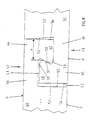
- the fastening system 1 is explained using the example of elongate rectangular panels 2 and 3, of which in Fig. 1 a section is shown.
- the fastening system 1 has arranged on the narrow sides of the panels holding profiles, which are formed as complementary positive locking profiles 4 and 5.
- the opposite positive locking profiles of a panel are each formed complementary. In this way, to any already laid panel 2 another panel 3 are attached.
- the positive locking profiles 4 and 5 are based on the prior art of the German utility model G 79 28 703 U1. In particular, on the form-locking profiles of the embodiment, which is disclosed in Figures 14, 15 and 16 and in the associated description part of G 79 28 703 U1.
- the positive locking profiles according to the invention are developed such that they allow an articulated and resilient connection of panels.
- One of the positive locking profiles 4 of the present invention is provided with a projecting from the narrow side projection 6.
- the underside of the projection 6, which faces the base in the installed state, has a cross-section with a convex curvature 7 for the purpose of the articulated connection.
- the convex curvature 7 is rotatably mounted in the complementary form-locking profile 5.
- the convex curvature 7 is formed in a circular section.
- the arranged below the projection 6 part 8 of the narrow side of the panel 3, which faces in the installed state of the base, is further from the free end of the projection 6 than the above the projection 6 arranged part 9 of the narrow side.
- the portion 8 of the narrow side arranged below the projection 6 recedes approximately twice as far from the free end of the projection 6 as the portion 9 of the narrow side arranged above the projection 6. This is due to the fact that the circular portion of the convex curvature 7 is formed relatively wide. As a result, the most projecting point of the convex curvature 7 of the projection 6 is arranged so that it is located approximately below the upper edge 10 of the panel 3.
- the above the projection 6 arranged part 9 of the narrow side occurs at the top of the panel 3 from the narrow side and forms a joint abutment surface 9a. Between this joint abutment surface 9a and the projection 6 of the panel 3, the part 9 of the narrow side is reset. This ensures that the part 9 of the narrow side always forms a closed top-side joint with the complementary narrow side of another panel 2.
- the convex curvature 7 of the projection 6 opposite upper side of the projection 6 has a short straight portion 11, which is also arranged parallel to the substrate U in the installed state. From this short portion 11 to the free end, the top of the projection 6 has an inclined material removal 12, which extends to the free end of the projection 6.
- a narrow side has a recess 20.
- This is essentially limited by a lower in the installed state the substrate U facing wall 21 and an upper wall 22.
- the lower wall 21 is provided with a concave curvature 23. This comes to the function of a bearing shell.
- the concave curvature 23 is also formed in a circular section. In order for the relatively wide concave curvature 23 to fit on the lower wall 21 of the recess 20, the lower wall 21 protrudes farther from the narrow side of the panel 2 than the upper wall 22.
- the concave curvature 23 forms at the free end of the lower wall 21 an undercut.
- the inside of the upper wall 22 of the recess 20 of the panel 2 is arranged according to the embodiment in the installed state parallel to the substrate U.
- the inside of the wall 21 has an inclined material removal 24, which extends to the free end of the lower wall 21.
- the material removal 24 adjoins the one end of the concave curvature 23 according to the exemplary embodiment.
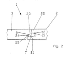
- the projection 6 of the panel 3 and the recess 20 of the panel 2 form, as in the Fig. 2 to see a common joint G.
- the above-discussed material removal 12 at the top of the projection 6 of the panel 3 and the material removal 24 of the lower wall 21 of the recess 20 of the panel 2 create in the installed state of the panels 2 and 3 movement clearances 13 and 25, which allow the joint G in a small angular range rotation.
- the short straight portion 11 of the top of the projection 6 of the panel 3 is in contact with the inside of the upper wall 22 of the recess 20 of the panel 2.
- the convex curvature 7 of the projection 6 bears against the concave curvature 23 of the lower wall 21 of the recess 20 of the panel 2.
- top facing side joint abutment surfaces 9a and 26 of two connected panels 2 and 3 are always clearly on each other.
- a simultaneous exact contact of the convex curvature 7 of the projection 6 of the panel 3 to the concave curvature 23 of the recess 20 of the panel 2 is not possible.
- Manufacturing tolerances would cause either the joint abutment surfaces 9a and 26 abut each other exactly or projection 6 / recess 20 exactly abut each other.
- the positive locking profiles are therefore designed so that the joint abutment surfaces 9a and 26 always exactly abut each other and projection 6 / recess 20 for an exact system can not be moved sufficiently far into each other.
- the manufacturing tolerances are in the order of one hundredth of a millimeter, also projection 6 / recess 20 nestle almost exactly against each other.
- Panels 2 and 3 with the described complementary positive locking profiles 4 and 5 can be fastened to each other in various ways.
- Fig. 3 is a panel 2 already laid with a recess 20, while a second panel 3 is inserted obliquely with a complementary projection 6 in the direction of arrow P in the recess 20 of the first panel 2. Thereafter, the second panel 3 is rotated about the common circle center K of the circular portions of the convex curvature 7 of the projection 6 and the concave curvature 23 of the recess 20 until the second panel 3 rests on the substrate U.
- FIG. 4 Another type of joining of the discussed panels 2 and 3 is in Fig. 4 shown, after which the first panel 2 is laid with a recess 20 and a second panel 3 is moved with a projection 6 in the laying plane and perpendicular to the positive locking profiles 4 and 5 in the direction of arrow P until the walls 21 and 22 of the recess 20 a little elastically expand and the convex curvature 7 of the projection 6, the undercut at the front end of the concave curvature 23 of the bottom wall has overcome and the final laying position is reached.
- the latter type of joining is preferably used for the short narrow sides of a panel, if they are provided with the same complementary positive locking profiles 4 and 5, as the long narrow sides of the panels.
- Fig. 5 the fastening system 1 is shown in use.
- the panels 2 and 3 lie on an irregular surface U.
- the first panel 2 with the form-locking profile 5 has been loaded on its upper side.
- the positive locking profile 4 connected to the positive locking profile 4 of the panel 3 has been lifted with.
- the joint G results in a kink between the two panels 2 and 3.
- the movement clearances 13 and 25 make room for the rotational movement of the joint.
- the joint G formed from both panels 2 and 3 has been moved a little way out of the laying plane upwards.
- the movement clearance 13 has been completely utilized for the rotation, so that the upper side of the projection 6 of the panel 3 rests against the inside of the wall 22 of the panel 2 in the region of the material removal 12.
- the joint is inherently resilient and does not impose any unnecessary and material-fatigue bending load on the positive-engagement profiles 4 and 4 involved.
- Fig. 6 is a joint movement of two laid panels 2 and 3 shown in the opposite direction of rotation.
- the laid on an irregular surface U panels 2 and 3 are bent downwards.
- the construction is designed so that when a buckling of the joint from the laying plane to the substrate U towards a much greater elastic deformation of the lower wall 21 of the recess 20 occurs as in the buckling from the laying plane upwards.
- the purpose of this measure is to be seen in the fact that the downwardly bent through panels 2 and 3 can not return to the laying level by unloading their own weight.
- the described positive locking profiles 4 and 5 are present integrally formed on the narrow sides of the panels 2 and 3. This is preferably done by a so-called formatting process, in which in one pass the form-locking 4 and 5 with several cascaded milling tools mill the shape of the narrow sides of the panels 2 and 3.
- the panels 2 and 3 of the described embodiment consist essentially of an MDF board with a thickness of 8 mm.
- the MDF board is wear-resistant and has a decorative coating on top.
- FIG. 7 two panels 2 and 3 in the laid state, wherein a fastening system 1 with a soft-elastic hardening filler 30 is used.
- the filler 30 is provided between all adjoining parts of the form-fitting connected narrow sides.
- the top-side joint 31 is closed with the filler, so that no moisture and no dirt can penetrate.
- caused in the bent state of two panels 2 and 3 in itself deformed filler 30 by its elasticity a provision of the panels 2 and 3 in the laying plane.
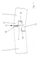
- Fig. 8 represents special holding profiles, which are provided for the short narrow sides of panels 40 and 41.
- Each panel has matching holding profiles 42 and 43 with complementary hook elements 44 and 45 on opposite short narrow sides.
- a right-hand retaining profile 42 of a first panel 40 can always be connected to a left-hand retaining profile 43 of a second panel 41.
- the short narrow sides of the panels 40 and 41 are shown in the nested state.
- the hook element 44 is formed from a web 46 which protrudes approximately perpendicularly from the narrow side and is arranged on the panel top O. In this case, at the free end of the web 46 a to the bottom V of the panels 40 and 41 facing hook projection 47 is arranged.
- the hook projection 47 is engaged with a hook projection 48 of the second panel 41.
- the hook element 45 of the second panel 41 is formed from a web 49 which projects from the narrow side of the second panel 41 and is arranged on the underside V of the second panel 41.
- the hook projection 48 is arranged at the free end of the web 49 and faces the panel top O of the panel 40. The hook projections 47 and 48 and the two panels 40 and 41 are interlocked.
- the hook projection 48 of the second panel 41 with the lower side web 49 rests against the upper side web 46 of the first panel 40 in the assembled state of the second panel 41.
- the hook projection 47 of the upper-side land 46 of the first panel 40 and the lower-side land 49 of the second panel 41 are provided with air L1 in the present embodiment.
- Fig. 8 engage behind holding surfaces 50 and 51 of the hook projections 47 and 48 such that the hook projections 47 and 48 are hooked into each other only by elastic deformation.
- an opening is formed which has the width a at its narrowest point. This is less than the width b of the hook projection 47 of the first panel 40 at its widest point.
- the hook projections 47 and 48 taper toward the webs 46 and 49.
- the holding surface 51 of the hook projection 47 of the first panel 40 at the upper and the lower end rounded.
- the holding surface 50 of the hook projection 48 of the second panel 41 This assists the interlocking of the hook projections 47 and 48, in which the holding profiles 42 and 43 are slowly elastically expanded during a joining movement running perpendicular to the laying plane. This facilitates the installation and protects the retaining profiles 42 and 43.
- the abutting support surfaces 50 and 51 of the cooperating panels 40 and 41 therefore nestle against each other in some areas.
- the resulting gaps may advantageously serve as glue pockets 53.
- a gap can also serve as a glue pocket 53.
- the end face 56 of the upper-side hook projection 4 of the first panel 40 which rests in the mounted state at least in the region of the panel top O and on the second panel 41.
- a gap widens, which is likewise designed as a glue pocket 53.
- FIG. 9 A second embodiment of a fastening system is in the Fig. 9 illustrated.
- the embodiment according to FIG. 9 differs from the embodiment according to Fig. 8 in that that of the two pairings web 49 / hook projection 47 or web 46 / hook projection 48, which bears against one another and which has the one which has an air gap L1, have changed.
- the basic function of the fastening system remains the same. This in turn results in a clear investment of the hook projection 47 and a seamless surface of the floor covering.
- Fig. 10 shows a schematic representation of a panel 41 with a holding profile 43 according to the invention. Schematically is registered as the undercut contour of the hook projection 48 by means of two cutting tools W1 and W2, which rotate about the axes X1 and X2, can be produced. The tools W1 and W2 create a recess 57 in which a complementary hook projection of another panel (not shown) can be hooked snapping.
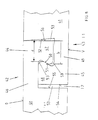
- FIG. 11 an alternative embodiment with special complementary retaining profiles 60 and 61 on the short narrow sides of panels 62 and 63 can be seen.
- hook elements 64 and 67 are provided which, like the above Embodiments have webs and hook projections.
- the embodiment according to Fig. 11 is constructed so that the end face 75 of the lower-side hook member 64 of the second panel 63 has at its free end a projecting locking element 65 which engages in an undercut recess 66 of the upper-side hook member 67 of the first panel 62.
- the hook elements 64 and 67 can be locked together with slight pressure and elastic deformation.
- the panels 62 and 63 are locked by the engaging in the recess 66 locking element 65 perpendicular to the laying plane.
- the locking of the panels 62 and 63 against pulling in the longitudinal direction thereof is accomplished by retaining surfaces 68 and 69 which are provided on hook projections 70 and 71 of the hook members 64 and 67.
- the protruding latching element 65 of the second panel 63 is formed in the illustrated embodiment as a bead which extends over the entire length of the narrow side.
- the undercut recess 66 of the first panel 62 is formed as an elongate throat, which receives the bead in the assembled state.
- the bead and throat can be milled by so-called formatting in one production pass.
- the bead and the throat must be interlocked under elastic deformation of the hook members 64 and 67.
- Fig. 12 a further embodiment is shown, which is based on the embodiment according to Fig. 11 based. Identical features of these two figures are provided with the same reference numerals.
- Fig. 12 constructed so that the front end 72 of the upper-side hook member 67 of the first panel 62 has at its free end a projecting locking element 73 which engages in an undercut recess 74 of the lower-side hook member 64 of the second panel 63.
- a slightly larger Pressure be exercised as in the embodiment according to Fig.
- the panels 62 and 63 are locked by the engaging in the recess 66 locking element 65 and the additional engaging in the recess 74 locking element 73 fixed as in the embodiment according to Fig. 11 ,
- the protruding latching elements 65 of the panels 62 and 63 are designed as beads which extend over the entire length of a narrow side.
- a protruding nose may be provided with a slope (not shown), wherein the slope of the nose is oriented so that with increasing progress of the joining operation, a gentle expansion of the corresponding hook element is accomplished.
- the undercut recesses 66 and 74 of the panels 62 and 63 are formed as elongated grooves which receive the beads in the assembled state.
- the bead and throat can be milled by so-called formatting in one production pass.
- each bead and throat must be interlocked under elastic deformation of the hook members 67 and 64.
- the embodiments differ from the Figures 11 and 12 in the interaction of the webs 46, 49 with the hook projections 71, 70th After Fig. 11 the web 46 abuts on the hook projection 71 and air is provided between the hook projection 70 and the web 49. According to Fig. 12 Air is between the web 46 and the hook projection 71 and the hook projection 70 abuts against the web 49.
Abstract
Den schmalen Seiten des Paneels wird ein komplementäres Paar Formschlussprofile mit je einem Hakenelement (44,64) zugeordnet. Eines der Hakenelemente (64) weist ein Rastelement (65) auf, das in eine hinterschnittene Vertiefung (66) eingreift.
Description
- Die Erfindung betrifft einen Fußbodenbelag, ein Paneel sowie ein Befestigungssystem für Paneele mit an den Schmalseiten der Paneele angeordneten Halteprofilen, insbesondere für Fußbodenpaneele, wobei sich gegenüberliegende Halteprofile als komplementäre Formschlussprofile ausgebildet sind.
- Das Befestigungssystem für Paneele dient insbesondere für Fußbodenpaneele, die auf einem Untergrund zu verlegen und deren Schmalseiten mit Halteprofilen versehen sind, wobei das Halteprofil einer langen Schmalseite und das Halteprofil der gegenüberliegenden Schmalseite sowie die Halteprofile der beiden übrigen kurzen Schmalseiten eines Paneels derart zueinanderpassen, dass an den freien Schmalseiten eines verlegten Paneels weitere Paneele befestigbar sind, wobei zumindest die Halteprofile der langen Schmalseiten der Paneele als einander zugeordnete Formschlußprofile ausgebildet und die Paneele durch eine drehende Fügebewegung aneinander befestigbar sind, dass das Formschlußprofil einer der langen Schmalseiten eines Paneels eine Aussparung und die gegenüberliegende Schmalseite dieses Paneels einen dazu passenden Vorsprung aufweist, dass die dem Untergrund zugewandte Wand der Aussparung innenseitig einen Querschnitt mit einer konkaven Wölbung aufweist und, dass das zugeordnete Formschlußprofil der gegenüberliegenden Schmalseite des Paneels einen Vorsprung aufweist, der an seiner dem Untergrund zugewandten Unterseite einen Querschnitt mit einer konvexen Wölbung aufweist, und dass die konvexe Wölbung des Vorsprungs und die konkave Wölbung der Aussparung im wesentlichen komplementär ausgebildet sind.
- Befestigungssysteme der genannten Art halten Paneele im fertig verlegten Zustand durch eine formschlüssige Verbindung zusammen. Insbesondere bei schwimmend auf einem Untergrund verlegten Fußbodenpaneelen verhindert eine formschlüssige Verbindung zwischen den Paneelen das Entstehen von Fugen, die beispielsweise durch Wärmeausdehnung bzw. Verkürzung bei Temperaturabfall entstehen können.
- Aus dem deutschen Gebrauchsmuster G 79 28 703 U1 ist ein gattungsgemäßes Befestigungssystem bekannt. Fußbodenpaneele mit einem derartigen Formschlußprofil lassen sich sehr leicht durch eine drehende Fügebewegung miteinander verbinden. Die Verbindung eignet sich prinzipiell auch für eine Mehrfachverlegung. Die entstehende formschlüssige Verbindung ist sehr steif und verhindert dadurch die Entstehung von Fugen sehr zuverlässig.
- Nachteiligerweise eignet sich das bekannte Befestigungssystem nur für besonders ebene Untergründe. Bei unregelmäßigen, rauhen und gewellten Untergründen schmiegt sich ein Paneelfußboden mit dem bekannten Befestigungssystem nur sehr schlecht an die Form des unregelmäßigen Untergrunds an. Wird beispielsweise ein Paneel, das im verlegten Zustand durch die benachbarten Paneele mit etwas Luft über einem gewellten Untergrund gehalten ist bei Belastung auf den Untergrund gedrückt, so biegen sich aneinander befestigte Fußbodenpaneele durch. Diese Durchbiegung beansprucht insbesondere die Verbindungsstellen mit den ineinandergreifenden Formschlußprofilen. Je nach Belastung werden die miteinander verbundenen Paneele nach unten oder oben durchgeknickt und dabei aus der normalen Verlegeebene herausgedrückt. Wegen der hohen Steifigkeit der Verbindung tritt eine hohe Belastung in den schwachen Querschnitten der Formschlußprofile auf, die dadurch sehr schnell beschädigt werden. Die Schädigung schreitet schnell voran bis ein Vorsprung oder eine Aussparungswand bricht.
- Auch bei einem ebenen Untergrund können Paneele eine wechselnde Durchbiegung erleiden dann nämlich, wenn auf dem Untergrund eine weiche Zwischenlage, beispielsweise eine trittschalldämmende Folie oder dergleichen verlegt ist. An einer belasteten Stelle wird die Zwischenlage eingedrückt und die Paneele knicken an ihren Verbindugsstellen durch.
- Der Erfindung liegt daher die Aufgabe zugrunde, das bekannte Befestigungssystem so weiterzubilden, dass die Steifigkeit der Verbindung zweier ineinandergefügter Formschlußprofile an die Beanspruchung angepaßt ist, die die Verbindungen bei Verlegung der Paneele auf einem unregelmäßigem Untergrund zu ertragen haben.
- Erfindungsgemäß wird die Aufgabe dadurch gelöst, dass durch die Formschlussprofile eine gelenkige und nachgiebige Verbindung der Paneele ermöglicht ist.
- Die Formschlußprofile der langen Schmalseiten zweier Paneele bilden im verlegten Zustand zweier Paneele ein gemeinsames Gelenk. Die dem Untergrund abgewandte Oberseite des Vorsprungs eines Paneels weist vorzugsweise eine schräge Materialabtragung auf, die sich bis zum freien Ende des Vorsprungs erstreckt.
- Günstigerweise ist die Dicke des Vorsprungs durch die Materialabtragung zum freien Ende hin zunehmend verringert. Durch die Materialabtragung ist ein Bewegungsfreiraum für das gemeinsame Gelenk geschaffen.
- Die neue Konstruktion gestattet eine gelenkige Bewegung zweier miteinander verbundener Paneele. Insbesondere können zwei miteinander verbundene Paneele an der Verbindungsstelle nach oben durchgeknickt werden. Liegt beispielsweise ein Paneel auf einem Untergrund mit einer Erhebung, so dass eine Schmalseite des Paneels bei Belastung auf den Untergrund gedrückt wird und sich - die gegenüberliegende Schmalseite aufwärts wippt, so wird ein an der aufwärts wippenden Schmalseite befestigtes zweites Paneel mit nach oben bewegt. Die dabei wirkenden Biegekräfte schädigen die schmalen Querschnitte der Formschlußprofile jedoch nicht. Statt dessen findet eine Gelenkbewegung statt. Ein mit dem vorgeschlagenen Befestigungsystem verlegter Fußboden weist somit eine an unregelmäßige rauhe oder gewellte Untergründe angepaßte Nachgiebigkeit auf. Das Befestigungsystem eignet sich daher besonders gut für Paneele zur Renovierung unregelmäßiger Fußböden in Altbauten. Selbstverständlich ist es auch für eine Verlegung von Paneelen auf einer weichen Zwischenlage besser geeignet als das bekannte Befestigungssystem.
- Die Konstruktion trägt dem Prinzip der "angepaßten Verformbarkeit" Rechnung. Dieses Prinzip beruht auf der Erkenntnis, dass sehr steife und dadurch vermeintlich stabile Verbindungsstellen hohe Kerbspannungen verursachen und dadurch leicht versagen. Um dies zu vermeiden, sollen Bauteile so gestaltet sein, dass sie eine auf den Einsatzzweck abgestimmte Nachgiebigkeit oder "angepaßte Verformbarkeit" aufweisen und auf diese Weise Kerbspannungen vermindert werden.
- Darüber hinaus sind die Formschlußprofile so ausgelegt, dass eine Belastung der Oberseite der Fußbodenpaneele im verlegten Zustand von der oberseitigen Wand der Aussparung eines ersten Paneels in den Vorsprung des zweiten Paneels und von dem Vorsprung des zweiten Paneels in die unterseitige Wand des ersten Paneels übertragen wird. Die Wände der Aussparung des ersten Paneels haben in verlegtem Zustand Kontakt mit der Ober- und Unterseite des Vorsprungs des zweiten Paneels. Die obere Wand der Aussparung hat jedoch nur in einem kurzen Bereich an dem freien Ende der oberen Wand der Aussparung Kontakt mit dem Vorsprung des zweiten Paneels. Auf diese Weise gestattet die Konstruktion unter geringer elastischer Verformung der Wände der Aussparung eine Gelenkbewegung zwischen dem Paneel mit der Aussparung und dem Paneel mit dem Vorsprung. Auf diese Weise ist die Steifigkeit der Verbindung bestens angepaßt an eine unregelmäßige Unterlage, welche zwangsläufig zu einer Knickbewegung zwischen aneinander befestigten Paneelen führt.
- Ein weiterer Vorteil wird darin gesehen, dass sich Paneele mit dem erfindungsgemäßen Befestigungssystem besser für eine mehrfache Verlegung eignen als Paneele mit dem bekannten Befestigungssystem, weil die Paneele mit dem erfindungsgemäßen Befestigungssystem auch nach langem Gebrauch auf einem unregelmäßigen Untergrund keine Vorschädigung der Formschlußprofile aufweisen. Die Formschlußprofile sind formstabil und haltbar. Sie können wesentlich länger benutzt und während ihres Lebenszyklus häufiger wiederverlegt werden.
- Vorteilhaft bilden die konvexe Wölbung des Vorsprungs und die konkave Wölbung der Aussparung im wesentlichen je einen Kreisabschnitt, wobei im verlegten Zustand der Kreismittelpunkt der Kreisabschnitte auf der Oberseite des Vorsprungs oder unterhalb der Oberseite des Vorsprungs angeordnet ist. Im letzteren Fall liegt der Kreismittelpunkt innerhalb des Querschnitts des Vorsprungs.
- Durch diese einfache Konstruktion ergibt sich ein Gelenk, dessen konvexe Wölbung des Vorsprungs ähnlich einer Gelenkkugel und die konkave Wölbung der Aussparung ähnlich einer Gelenkpfanne ausgebildet sind, wobei im Unterschied zu einem Pfannengelenk selbstverständlich nur eine ebene Drehbewegung aber keine sphärische Drehbewegung möglich ist.
- In einer günstigen Weiterbildung ist der weitest hervorstehende Punkt der konvexen Wölbung des Vorsprungs eines Paneels so angeordnet, dass er sich etwa unterhalb der Oberkante des Paneels befindet. Dadurch ergibt sich ein im Verhältnis zur Gesamtdicke des Paneels relativ starker Querschnitt für den Vorsprung. Außerdem bietet die konkave Wölbung der Aussparung eine ausreichend große Hinterschneidung für die konvexe Wölbung des Vorsprungs, so dass diese durch in der Verlegeebene wirkende Zugkräfte kaum auseinander zu bewegen sind.
- Die Gelenkeigenschaften zweier miteinander verbundener Paneele können weiter verbessert werden, wenn die dem Untergrund zugewandte Wand der Aussparung eines Paneels auf ihrer Innenseite eine schräge Materialabtragung aufweist, die sich bis zum freien Ende der Wand erstreckt und die Wandstärke dieser Wand zum freien Ende zunehmend dünner ist. Dabei ist durch die Materialabtragung im verlegten Zustand zweier Paneele ein Bewegungsfreiraum für das gemeinsame Gelenk geschaffen. Mit dieser Verbesserung wird der Anteil an elastischer Verformung der Wände der Aussparung während der Durchbiegung der verlegten Paneele nach oben weiter verringert.
- Zweckmäßig ist es auch, wenn die Aussparung eines Paneels zur Verbindung mit dem Vorsprung eines weiteren Paneels durch eine federelastische Verformung ihrer unteren Wand aufweitbar ist und, dass die während des Fügens auftretende federelastische Verformung der unteren Wand im fertig verbundenen Zustand zweier Paneele wieder zurückgenommen ist. Die Formschlußprofile werden dadurch nur für den Fügevorgang und während einer Gelenkbewegung elastisch verformt und unterliegen, wenn sie nicht belastet sind, keiner elastischen Verspannung.
- Nützlich ist es, wenn die Halteprofile der kurzen Schmalseiten eines Paneels ebenfalls als einander zugeordnete Formschlußprofile ausgebildet und durch eine geradlinige Fügebewegung aneinander befestigbar sind.
- Einfacherweise sind die Halteprofile der kurzen Schmalseite eines Paneels mit herkömmlichen etwa rechteckigen Nut- und Federquerschnitten versehen. Diese sind sehr einfach und kostengünstig herstellbar und lassen sich nach dem Fügen der langen Schmalseiten eines Paneels besonders einfach durch seitliches Verschieben ineinander bringen. Auch lassen sich die langen Schmalseiten der Paneele auf ihrer ganzen Länge in paralleler Richtung ineinander schieben.
- Eine andere Weiterbildung der kurzen Schmalseite eines Paneels sieht vor, dass die Querschnitte der Formschlußprofile im wesentliche den Querschnitten der Formschlußprofile der langen Schmalseiten des Paneels entsprechen. Die Fähigkeit, zwei Paneele auch an deren kurzen Schmalseiten gelenkig zu verbinden, kommt der Nachgiebigkeit eines Fußbodenbelags zugute.
- Bevorzugt sind die Formschlußprofile einstückig an den Schmalseiten der Paneele angeformt. Die Paneele lassen sich sehr einfach und mit geringem Verschnitt herstellen.
- Besonders geeignet sind die erfindungsgemäßen Formschlußprofile, wenn die Paneele im wesentlichen aus einem MDF (Medium Density Fiberboard), HDF (High Densitiy Fiberboard) oder einem Spanplattenmaterial bestehen. Diese Materialien sind einfach zu bearbeiten und erhalten, beispielsweise durch eine spanende Bearbeitung, eine ausreichende Oberflächenqualität. Außerdem weisen diese Materialien eine hohe Formstabilität der gefrästen Profile auf.
- Ein weiterer Nutzen ergibt sich, wenn im verlegten Zustand der Paneele die Bewegungsfreiräume für die gemeinsamen Gelenke mit einem weichelastisch aushärtendem Füllstoff versehen sind. Dieser Füllstoff verschließt vorzugsweise alle Fugen und insbesondere die oberseitige Fuge derart, dass keine Feuchtigkeit und kein Schmutz eindringen kann. Bei einer Gelenkbewegung der miteinander verbundenen Paneele wird der weichelastische Füllstoff je nach Drehrichtung der Gelenkbewegung gequetscht oder gedehnt. Er haftet dabei stets an den Kontaktflächen der Schmalseiten der Paneele und nimmt beim Rückgang der Gelenkbewegung wieder seine Ausgangsform an. Der Füllstoff trägt durch seine elastische innere Verformung zur Rückstellung des Gelenks bei.
- Eine alternative Ausbildung des Befestigungsystems sieht vor, dass eine kurze Schmalseite eines Paneels ein erstes Hakenelement und die gegenüberliegende kurze Schmalseite des Paneels ein zu dem ersten Hakenelement komplementäres Hakenelement aufweist und, dass die Hakenelemente mit Halteflächen versehen sind, durch die die Paneele im montierten Zustand derart gegeneinander gehalten sind, dass sich an den kurzen Schmalseiten eine spaltfrei aneinanderstoßende Oberfläche der Paneele ergibt.
- Zur Verlegung der Paneele müssen zunächst die Formschlußprofile der langen Schmalseiten der Paneele zusammengefügt werden. Hierfür wird ein Paneel schräg angestellt und mit dem Vorsprung einer langen Schmalseite in die Aussparung der langen Schmalseite eines verlegten Paneels gesteckt. Dadurch bildet sich das gemeinsame Gelenk. Dananch wird das Paneel in der schrägen Position gehalten und in seiner Längsrichtung so weit verschoben, bis es gegen die kurze Schmalseite eines benachbarten Paneels stößt. In dieser Position überlappen sich die Hakenelemente der kurzen Schmalseiten der benachbarten Paneele. Wenn nun das schräg angestellte Paneel mittels des Gelenks heruntergeklappt wird, fügen sich die überlappenden Hakenelemente ineinander. Es ergibt sich ein Hintergreifen, das die Paneele gegen Auseinanderziehen in deren Längsrichtung verriegelt. Durch die Hakenelemente ist ein Maß an Hinterschneidung erreichbar, das bei etwa einem Drittel der gesamten Paneeldicke liegt. Die Art der Verriegelung der kurzen Schmalseiten der Paneele erinnert dabei an sich seitlich hintergreifende Dachpfannen.
- Einfacherweise ist das erste Hakenelement aus einem von der kurzen Schmalseite etwa senkrecht hervorstehenden und an der Paneeloberseite angeordneten Steg gebildet, wobei an dem freiem Ende des Stegs ein zur Unterseite des Paneels weisender Hakenvorsprung angeordnet ist und das zweite Hakenelement aus einem von der gegenüberliegenden kurzen Schmalseite hervorstehenden und an der Unterseite des Paneels angeordneten Steg gebildet, wobei an dem freiem Ende dieses Stegs ein zur Paneeloberseite weisender Hakenvorsprung angeordnet ist.
- Die Oberseite des Paneels geht von dem Bereich mit der Dicke des kompletten Paneels mit einer Dickenabstufung über in den Steg. Der Steg weist etwa eine Dicke auf, die einem Drittel der Paneeldicke entspricht. Das gleiche gilt für die Unterseite des Paneels. Dem Hakenelement der Oberseite gegenüberliegend geht der unterseitige Steg von dem Bereich der kompletten Dicke des Paneels mit einer Dickenabstufung über in den Steg, der ebenfalls etwa ein Drittel der Dicke des Paneels aufweist. Die Stege sowie die Hakenvorsprünge sind somit relativ massiv ausgebildet. Daher ergibt sich eine Verbesserung der Festigkeit und Haltbarkeit für das erfindungsgemäße Befestigungssystem.
- Vorteilhaft liegt der Hakenvorsprung des unterseitigen Stegs im montierten Zustand eines Paneels an dem oberseitigen Steg eines zweiten Paneels an. Außerdem ist zwischen dem Hakenvorsprung des oberseitigen Stegs des zweiten Paneels und dem unterseitigen Steg des ersten Paneels Luft vorgesehen.
- Selbstverständlich ist dies auch umkehrbar, so dass zwischen dem Hakenvorsprung des unterseitigen Stegs des ersten Paneels und dem oberseitigen Steg des zweiten Paneels Luft vorgesehen ist. Es kommt darauf an, dass stets eine Paarung Steg/Hakenvorsprung gefügter Hakenelemente im montierten Zustand eindeutig aneinander anliegen und die andere Paarung Steg/Hakenvorsprung derselben Hakenelemente Luft aufweist. Wäre das Befestigungssystem so konstruiert, dass stets beide Paarungen Steg/Hakenvorsprung aneinander anliegen, so würden durch Toleranzen bei der Fertigung der Halteprofile keine eindeutige Anlage erreicht und mal die eine und mal die andere Paarung Steg/Hakenvorsprung anliegen.
- Eine Weiterbildung des Befestigungssystems sieht vor, dass die Halteflächen der Hakenvorsprünge sich derart hintergreifen, dass sie nur durch elastische Verformung ineinander verhakbar sind. Auf diese Weise kann verhindert werden, dass die Hakenelemente beispielsweise wegen eines unebenen Untergrunds bei Belastung auseinanderbewegt werden können. Bei einer Belastung eines Paneels wird das verbundene Paneel mit dem belasteten Paneel in die gleiche Richtung bewegt. Die Fügestelle bleibt zusammen.
- Einfacherweise sind die Halteflächen der Hakenvorsprünge schräg gestellt und verjüngen sich die Hakenvorsprünge von ihren freien Enden zu den Stegen hin. Weiterhin liegen die Halteflächen komplementärer Hakensprünge zumindest bereichsweise aneinander an. Hierbei handelt es sich um eine einfache Gestaltung der mit einer Hinterschneidung versehenen Hakenvorsprünge, weil als Hinterschneidung eine einfach herstellbare ebene Haltefläche vorgesehen ist.
- Ein weiterer Nutzen ergibt sich, wenn die Stirnseite des oberseitigen Hakenvorsprungs des einen Paneels im montierten Zustand zumindest in dem Bereich der Paneeloberseite an dem zweiten Paneel anliegt und zwischen dem unterseitigen Hakenvorsprung des zweiten Paneels und der Stirnseite des ersten Paneels Luft vorgesehen ist. Diese Maßnahme dient wiederum dazu, durch die konstruktive Gestaltung eine stets eindeutige Anlage zweier verbundener Paneele zu schaffen.
- An der Unterseite der Paneele, die auf eine Unterlage, beispielsweise einen Estrich, aufgelegt wird, kann im Bereich der Fügestelle ein Luftspalt zwischen den Paneelen geduldet werden.
- Eine alternative Ausführungsform mit Hakenelementen an den kurzen Schmalseiten des Paneels ist so konstruiert, dass wenigstens eine der Stirnseiten eines der Hakenelemente der Paneele an ihrem freien Ende ein vorstehendes Rastelement aufweist, das in eine hinterschnittene Vertiefung des anderen Hakenelements des Paneels greift. Diese Konstruktion hat sich als besonders gut handhabbar herausgestellt, weil sich die Halteprofile mit leichtem Druck und unter elastischer Verformung ineinander verrasten lassen. Außerdem weisen die Halteelemente eine gute Verschleißfestigkeit auf, was eine Mehrfachverlegung begünstigt. Die Verschleißfestigkeit ist deshalb gut, weil verschiedene Arretierfunktionen von verschiedenen Halteelementbereichen ausgeübt werden und die Beanspruchung des Halteelements so verteilt auftritt. Die Paneele werden zum Beispiel durch das Rastelement und die Vertiefung senkrecht zur Verlegeebene arretiert. Die Arretierung der Paneele gegen Auseinanderziehen in deren Längsrichtung wird hingegen durch die Halteflächen der Hakenvorsprünge bewerkstelligt.
- Einfacherweise ist das vorstehende Rastelement des ersten Paneels als Wulst ausgebildet, die sich über die gesamte Länge der Schmalseite erstreckt und die hinterschnittene Vertiefung des zweiten Paneels als langgestreckte Kehle ausgebildet, die die Wulst im zusammengefügten Zustand aufnimmt. Zum Fügen müssen Wulst und Kehle unter einer elastischen Verformung der Hakenelemente ineinandergefügt werden.
- Diese Ausführungsform des Befestigungsystems eignet sich dann, wenn keine Verleimung vorgenommen wird, besonders gut für eine Mehrfachverlegung. Um verlegte Paneele wieder aufzunehmen, hebt man zweckmäßig zuerst eine Reihe nebeneinanderliegender Paneele so an, dass sich diese in dem Gelenk schräg nach oben drehen. Dann werden die Vorsprünge in schräger Richtung aus den Aussparungen herausgezogen und das Gelenk auseinandergenommen. Die Paneele sind dann nur noch an den kurzen Schmalseiten verbunden. Es empfiehlt sich die ineinandergefügten Halteelemente der kurzen Schmalseiten in ihrer Längserstreckung auseinanderzuziehen, um auf diese Weise bei der Zerlegung eine materialermüdende Verformung der Hakenelemente zu vermeiden.
- Eine weitere Verbesserung wird darin gesehen, dass die im montierten Zustand zweier Paneele mit Luft versehenen Bereiche Leimtaschen bilden. Neben der Verwendung des vorgeschlagenen Befestigungssystems für eine leimfreie Verlegung von Fußbodenpaneelen eignet es sich besonders gut für eine Verbindung mit Leim. Zu diesem Zweck können diejenigen Stellen der Halteprofile, die mit Leim versehen sein müssen, beispielsweise in einer Gebrauchsanweisung oder durch Markierungen an dem Halteprofil selbst gekennzeichnet sein. Auf diese Weise kann der Benutzer sehr genau dort Leim anbringen, wo sich im montierten Zustand zweier Paneele Leimtaschen ergeben.
- In den überwiegenden Anwendungsfällen der Fußbodenpaneele wird die verleimte Verlegung als zweckmäßigste Verlegeart angesehen. Dies, weil die Haltbarkeit der Paneele deutlich verbessert wird. Die Verleimung der Halteprofile bewirkt, dass ein Eindringen von Schmutz und Feuchtigkeit in die Fugen nahezu verhindert wird. Die Feuchtigkeitsaufnahme und das Quellen der Paneele im Fügebereich der Halteprofile wird dadurch minimiert.
- Selbstverständlich können Anwendungsfälle vorkommen, für die eine leimfreie Verlegung zu bevorzugen ist. Beispielsweise dann, wenn ein Fußbodenbelag häufig verlegt wieder aufgenommen und neu verlegt werden muß, z.B. bei Fußböden im Messebau.
- Bevorzugt sind die Paneele aus einem beschichteten Trägerstoff gebildet und die Halteprofile einstückig an den Schmalseiten der Paneele angeformt. Es hat sich erwiesen, dass die Festigkeit moderner Trägerstoffe, wie beispielsweise mitteldichter Faserplatten (MDF) oder hochdichter Faserplatten (HDF), die mit einer abriebfesten Nutzschicht versehen sind, sich besonders zum Einsatz des vorgeschlagenen Befestigungssystems eignen. Selbst nach mehrmaliger Verlegung sind die Halteprofile noch so gut in Form, dass eine sichere Verbindung auch auf unebenem Untergrund möglich ist.
- Nachstehend ist die Erfindung beispielhaft in einer Zeichnung dargestellt und anhand der
Figuren 1 bis 6 detailliert beschrieben. Es zeigen: - Fig. 1
- ein Befestigungssystem ausschnittsweise anhand der Querschnitte zweier Paneele vor dem Ineinanderfügen,
- Fig. 2
- das Befestigungssystem gemäß
Fig. 1 im aneinander befestigten Zustand, - Fig. 3
- einen Fügevorgang, bei dem der Vorsprung eines Paneels in Pfeilrichtung in die Aussparung eines zweiten Paneels gesteckt und das erste Paneel nachfolgend mit einer Drehbewegung arretiert wird,
- Fig. 4
- einen weiteren Fügevorgang, bei dem der Vorsprung eines ersten Paneels parallel zur Verlegeebene in die Aussparung eines zweiten Paneels eingeschoben wird,
- Fig. 5
- das Befestigungssystem im befestigten Zustand gemäß
Fig. 2 , wobei das gemeinsame Gelenk aus der Verlegeebene nach oben bewegt ist und die beiden Paneele einen Knick bilden, - Fig. 6
- das Befestigungssystem im verlegten Zustand gemäß
Fig. 2 , wobei das Gelenk aus der Verlegeebene nach unten bewegt ist und die beiden Paneele einen Knick bilden, - Fig. 7
- ein Befestigungssystem im verlegten Zustand zweier Paneele mit einem Füllstoff zwischen den Formschlußprofilen der Schmalseiten.
- Fig. 8
- besondere Halteprofile für die kurzen Schmalseiten eines Paneels im ineinandergefügten Zustand,
- Fig. 9
- eine weitere Ausführungsform besonderer Halteprofile für die kurzen Schmalseiten eines Paneels im ineinandergefügten Zustand,
- Fig.10
- eine schematische Darstellung eines Halteprofils mit einem unterseitigen Steg sowie einer Darstellung zweier Zerspanungswerkzeuge zur Herstellung der Hinterschneidung,
- Fig.11
- eine dritte Ausführungsform besonderer Halteprofile für die kurzen Schmalseiten eines Paneels im ineinandergefügten Zustand,
- Fig.12
- eine Ausführungsform gemäß
Fig. 11 , die um ein zusätzliches Rastelement ergänzt ist, - Nach der Zeichnung ist das Befestigungssystem 1 am Beispiel langgestreckter rechteckiger Paneele 2 und 3 erläutert, von denen in
Fig. 1 ein Ausschnitt dargestellt ist. Das Befestigungssystem 1 weist an den Schmalseiten der Paneele angeordnete Halteprofile auf, die als komplementäre Formschlußprofile 4 und 5 ausgebildet sind. Die sich gegenüberliegenden Formschlußprofile eines Paneels sind jeweils komplementär ausgebildet. Auf diese Weise kann an jedes bereits verlegte Paneel 2 ein weiteres Paneel 3 angebracht werden. - Die Formschlußprofile 4 und 5 basieren auf dem Stand der Technik des deutschen Gebrauchsmusters G 79 28 703 U1. Insbesondere auf den Formschlußprofilen des Ausführungsbeispiels, das in den Figuren 14, 15 und 16 sowie in dem zugehörigen Beschreibungsteil der G 79 28 703 U1 offenbart ist.
- Die erfindungsgemäßen Formschlußprofile sind derart weitergebildet, dass sie eine gelenkige und nachgiebige Verbindung von Paneelen ermöglichen.
- Eines der Formschlußprofile 4 der vorliegenden Erfindung ist mit einem von der Schmalseite abstehenden Vorsprung 6 versehen. Die Unterseite des Vorsprungs 6, die im verlegten Zustand der Unterlage zugewandt ist, weist zum Zweck der gelenkigen Verbindung einen Querschnitt mit einer konvexen Wölbung 7 auf. Die konvexe Wölbung 7 ist in dem komlementären Formschlußprofil 5 drehgelagert. In dem dargestellten Ausführungsbeispiel ist die konvexe Wölbung 7 kreisabschnittsförmig ausgebildet. Der unterhalb des Vorsprungs 6 angeordnete Teil 8 der Schmalseite des Paneels 3, der im verlegten Zustand der Unterlage zugewandt ist, steht von dem freien Ende des Vorsprungs 6 weiter zurück als der oberhalb des Vorsprungs 6 angeordnete Teil 9 der Schmalseite. In dem gezeigten Ausführungsbeispiel tritt der unterhalb des Vorsprungs 6 angeordnete Teil 8 der Schmalseite etwa doppelt so weit von dem freien Ende des Vorsprungs 6 zurück, wie der oberhalb des Vorsprungs 6 angeordnete Teil 9 der Schmalseite. Dies liegt darin begründet, dass der Kreisabschnitt der konvexen Wölbung 7 relativ breit ausgebildet ist. Dadurch ist der weitest hervorstehende Punkt der konvexen Wölbung 7 des Vorsprungs 6 so angeordnet, dass er sich etwa unterhalb der Oberkante 10 des Paneels 3 befindet.
- Der oberhalb des Vorsprungs 6 angeordnete Teil 9 der Schmalseite tritt an der Oberseite des Paneels 3 von der Schmalseite hervor und bildet eine Fugenstoßfläche 9a. Zwischen dieser Fugenstoßfläche 9a und dem Vorsprung 6 des Paneels 3 ist der Teil 9 der Schmalseite zurückgesetzt. Dies gewährleistet, dass der Teil 9 der Schmalseite immer eine geschlossene oberseitige Fuge mit der komplementäten Schmalseite eines weiteren Paneels 2 bildet.
- Die der konvexen Wölbung 7 des Vorsprungs 6 gegenüberliegende Oberseite des Vorsprungs 6 weist ein kurzes gerades Teilstück 11 auf, das im verlegten Zustand ebenfalls parallel zum Untergrund U angeordnet ist. Von diesem kurzen Teilstück 11 zum freien Ende hin weist die Oberseite des Vorsprungs 6 eine schräge Materialabtragung 12 auf, die sich bis zum freien Ende des Vorsprungs 6 erstreckt.
- Das zu dem besprochenen Formschlußprofil 4 komplementäre Formschlußprofil 5 einer Schmalseite weist eine Aussparung 20 auf. Diese ist im wesentlichen von einer unteren im verlegten Zustand dem Untergrund U zugewandten Wand 21 und einer oberen Wand 22 begrenzt. Auf der Innenseite der Aussparung 20 ist die untere Wand 21 mit einer konkaven Wölbung 23 versehen. Dieser kommt die Funktion einer Lagerschale zu. Die konkave Wölbung 23 ist ebenfalls kreisabschnittsförmig ausgebildet. Damit die relativ breite konkave Wölbung 23 an der unteren Wand 21 der Aussparung 20 Platz findet, steht die untere Wand 21 weiter von der Schmalseite des Paneels 2 hervor als die obere Wand 22. Die konkave Wölbung 23 bildet an dem freien Ende der unteren Wand 21 eine Hinterschneidung. Im fertig verlegten Zustand zweier Paneele 2 und 3 wird diese Hinterschneidung von dem Vorsprung 6 des zugeordneten Formschlußprofils 4 des benachbarten Paneels 3 hintergriffen. Das Maß an Hintergreifung, die Differenz also zwischen der dicksten Stelle des freien Endes der unteren Wand sowie der Dicke der unteren Wand an dem tiefsten Punkt der konkaven Wölbung 23 ist so abgestimmt, dass ein guter Kompromiß zwischen einer gelenkigen Nachgiebigkeit zweier Paneele 2 und 3 sowie einem guten Halt gegen ein Auseinanderziehen der Formschlußprofile 4 und 5 in der Verlegeebene gegeben ist.
- Das Befestigungssystem des Standes der Technik gemäß der Figuren 14, 15 und 16 des Gebrauchsmusters G 79 28 703 U1 weist demgegenüber ein erheblich größeres Maß an Hinterschneidung auf. Es ergeben sich dadurch außerordentlich steife Verbindungsstellen, die durch die Beanspruchung auf einem unregelmäßigen Untergrund U hohe Kerbspannungen verursachen.
- Die Innenseite der oberen Wand 22 der Aussparung 20 des Paneels 2 ist nach dem Ausführungsbeispiel im verlegten Zustand parallel zu dem Untergrund U angeordnet.
- Auf der dem Untergrund U zugewandten unteren Wand 21 der Aussparung 20 des Paneels 2 weist die Innenseite der Wand 21 eine schräge Materialabtragung 24 auf, die sich bis zum freien Ende der unteren Wand 21 erstreckt. Dadurch wird die Wandstärke dieser Wand zum freien Ende zunehmend dünner. Die Materialabtragung 24 schließt sich gemäß dem Ausführungsbeispiel an das eine Ende der konkaven Wölbung 23 an.
- Der Vorsprung 6 des Paneels 3 und die Aussparung 20 des Paneels 2 bilden, wie in der
Fig. 2 zu sehen, ein gemeinsames Gelenk G. Die oben besprochene Materialabtragung 12 an der Oberseite des Vorsprungs 6 des Paneels 3 sowie die Materialabtragung 24 der unteren Wand 21 der Aussparung 20 des Paneels 2 schaffen im verlegten Zustand der Paneele 2 und 3 Bewegungsfreiräume 13 beziehungsweise 25, die dem Gelenk G in einem kleinen Winkelbereich eine Drehung ermöglichen. - Im verlegten Zustand steht das kurze gerade Teilstück 11 der Oberseite des Vorsprungs 6 des Paneels 3 mit der Innenseite der oberen Wand 22 der Aussparung 20 des Paneels 2 in Kontakt. Außerdem liegt die konvexe Wölbung 7 des Vorsprungs 6 an der konkaven Wölbung 23 der unteren Wand 21 der Aussparung 20 des Paneels 2 an.
- Die der Oberseite zugewandten seitlichen Fugenstoßflächen 9a und 26 zweier verbundener Paneele 2 und 3 liegen immer eindeutig aneinander an. In der Praxis ist eine gleichzeitige exakte Anlage der konvexen Wölbung 7 des Vorsprung 6 des Paneels 3 an der konkaven Wölbung 23 der Aussparung 20 des Paneels 2 nicht möglich. Fertigungstoleranzen würden dazu führen, dass entweder die Fugenstoßflächen 9a und 26 exakt aneinander anliegen oder Vorsprung 6/Aussparung 20 exakt aneinander anliegen. In der Praxis sind die Formschlußprofile daher so ausgelegt, dass die Fugenstoßflächen 9a und 26 immer exakt aneinander anliegen und Vorsprung 6/Aussparung 20 für eine exakte Anlage nicht genügend weit ineinander bewegt werden können. Da die Fertigungstoleranzen jedoch in der Größenordnung von hundertstel Millimeter liegen, schmiegen sich auch Vorsprung 6/Aussparung 20 nahezu exakt aneinander an.
- Paneele 2 und 3 mit den beschriebenen komplementären Formschlußprofilen 4 und 5 lassen sich auf verschiedene Weisen aneinander befestigen. Nach
Fig. 3 ist ein Paneel 2 mit einer Aussparung 20 bereits verlegt, während ein zweites Paneel 3 mit einem komplementären Vorsprung 6 in Pfeilrichtung P schräg stehend in die Aussparung 20 des ersten Paneels 2 eingesteckt wird. Danach wird das zweite Paneel 3 um den gemeinsamen Kreismittelpunkt K der Kreisabschnitte der konvexen Wölbung 7 des Vorsprungs 6 und der konkaven Wölbung 23 der Aussparung 20 gedreht, bis das zweite Paneel 3 auf dem Untergrund U aufliegt. - Eine weitere Fügeart der besprochenen Paneele 2 und 3 ist in
Fig. 4 dargestellt, wonach das erste Paneel 2 mit einer Aussparung 20 verlegt ist und ein zweites Paneel 3 mit einem Vorsprung 6 in der Verlegeebene und senkrecht zu den Formschlußprofilen 4 und 5 in Pfeilrichtung P verschoben wird, bis sich die Wände 21 und 22 der Aussparung 20 ein wenig elastisch aufweiten und die konvexe Wölbung 7 des Vorsprungs 6 die Hinterschneidung an dem vorderen Ende der konkaven Wölbung 23 der unteren Wand überwunden hat und die endgültige Verlegeposition erreicht ist. - Letztere Fügeart wird bevorzugt für die kurzen Schmalseiten eines Paneels verwendet, wenn diese mit den gleichen komplementären Formschlußprofilen 4 und 5 versehen sind, wie die langen Schmalseiten der Paneele.
- In
Fig. 5 ist das Befestigungssystem 1 im Einsatz dargestellt. Die Paneele 2 und 3 liegen auf einem unregelmäßigen Untergrund U. Das erste Paneel 2 mit dem Formschlußprofil 5 ist auf seiner Oberseite belastet worden. Dadurch ist die Schmalseite des Paneels 2 mit dem Formschlußprofil 5 angehoben worden. Das mit dem Formschlußprofil 5 verbundene Formschlußprofil 4 des Paneels 3 ist mit angehoben worden. Durch das Gelenk G ergibt sich ein Knick zwischen den beiden Paneelen 2 und 3. Die Bewegungsfreiräume 13 und 25 schaffen Platz für die Drehbewegung des Gelenks. Das aus beiden Paneelen 2 und 3 gebildete Gelenk G ist ein Stück weit aus der Verlegeebene nach oben bewegt worden. Der Bewegungsfreiraum 13 ist für die Drehung komplett ausgenutzt worden, so dass die Oberseite des Vorsprungs 6 des Paneels 3 im Bereich der Materialabtragung 12 an der Innenseite der Wand 22 des Paneels 2 anliegt. Die Verbindungsstelle ist in sich nachgiebig und zwingt den beteiligten Formschlußprofilen 4 und 4 keine unnötige und materialermüdende Biegebelastung auf. - Die bei Formschlußprofilen nach dem Stand der Technik früh eintretende Schädigung durch Bruch des Vorsprungs oder der wände der Formschlußprofile wird somit vermieden.
- Ein weiterer Vorteil ergibt sich bei einer Gelenkbewegung gemäß der
Fig. 5 . Dieser ist darin zu sehen, dass die beiden Paneele nach Entlastung durch ihr Eigengewicht wieder in ihre Verlegeebene zurückfallen. Eine geringe elastische Verformung der Wände der Aussparung liegt auch in diesem Fall vor. Diese elastische Verformung unterstützt das Zurückfallen der Paneele in die Verlegeebene. Es kommt lediglich zu einer sehr geringen elastische Verformung, weil der Drehpunkt des Gelenks, der durch die kreisabschnittsförmigen Wölbungen 7 und 23 festgelegt ist, sich innerhalb des Querschnitts des Vorsprungs 6 des Paneels 3 befindet. - In
Fig. 6 ist eine Gelenkbewegung zweier verlegter Paneele 2 und 3 in entgegengesetzter Drehrichtung dargestellt. Die auf einem unregelmäßigen Untergrund U verlegten Paneele 2 und 3 sind nach unten durchgeknickt. Die Konstruktion ist so ausgelegt, dass bei einem Durchknicken der Verbindungsstelle aus der Verlegeebene zum Untergrund U hin eine deutlich stärkere elastische Verformung der unteren Wand 21 der Aussparung 20 auftritt als bei der Durchknickung aus der Verlegeebene nach oben. Der Sinn dieser Maßnahme ist darin zu sehen, dass die nach unten durchgeknickten Paneele 2 und 3 nach Entlastung nicht durch ihr Eigengewicht wieder in die Verlegeebene zurückkehren können. Die stärkere elastische Verformung der unteren Wand 21 der Aussparung 20 erzeugt jedoch eine Spannkraft, die die Paneele 2 und 3 nach Entlastung sofort wieder federelastisch in die Verlegeebene zurück bewegt. - Die beschriebenen Formschlußprofile 4 und 5 sind vorliegend einstückig an den Schmalseiten der Paneele 2 und 3 angeformt. Dies geschieht vorzugsweise durch einen sogenannten Formatiervorgang, bei dem in einem Durchlauf die Formschlußprotile 4 und 5 mit mehreren hintereinandergeschalteten Fräswerkzeugen die Form der Schmalseiten der Paneele 2 und 3 fräsen. Die Paneele 2 und 3 des beschriebenen Ausführungsbeispiels bestehen im wesentlichen aus einer MDF-Platte mit einer Dicke von 8 mm. Die MDF-Platte ist an Ihrer Oberseite verschleißfest und dekorativ beschichtet. An Ihrer Unterseite ist eine sogenannte Gegenzugschicht angebracht, die die von der oberseitigen Beschichtung verursachten Eigenspannungen kompensiert.
- Schließlich zeigt
Fig. 7 zwei Paneele 2 und 3 im verlegten Zustand, wobei ein Befestigungsystem 1 mit einem weichelastisch aushärtenden Füllstoff 30 zum Einsatz kommt. Der Füllstoff 30 ist zwischen allen aneinandergrenzenden Teilen der formschlüssig verbundenen Schmalseiten vorgesehen. Insbesondere die oberseitige Fuge 31 ist mit dem Füllstoff verschlossen, damit keine Feuchtigkeit und kein Schmutz eindringen können. Außerdem bewirkt der im geknickten Zustand zweier Paneele 2 und 3 in sich verformte Füllstoff 30 durch seine Elastizität eine Rückstellung der Paneele 2 und 3 in die Verlegeebene. -
Fig. 8 stellt besondere Halteprofile dar, die für die kurzen Schmalseiten von Paneelen 40 und 41 vorgesehen sind. Jedes Paneel weist an gegenüberliegenden kurzen Schmalseiten zueinander passende Halteprofile 42 und 43 mit komplementären Hakenelementen 44 und 45 auf. Auf diese Weise läßt sich stets ein rechtes Halteprofil 42 eines ersten Paneels 40 mit einem linken Halteprofil 43 eines zweiten Paneels 41 verbinden. InFig. 8 sind die kurzen Schmalseiten der Paneel 40 und 41 im ineinandergefügten Zustand dargestellt. Das Hakenelement 44 ist aus einem von der Schmalseite etwa senkrecht hervorstehenden und an der Paneeloberseite O angeordneten Steg 46 gebildet. Dabei ist an dem freien Ende des Stegs 46 ein zur Unterseite V der Paneele 40 und 41 weisender Hakenvorsprung 47 angeordnet. Der Hakenvorsprung 47 ist mit einem Hakenvorsprung 48 des zweiten Paneels 41 in Eingriff. Das Hakenelement 45 des zweiten Paneels 41 ist aus einem Steg 49 gebildet, der von der Schmalseite des zweiten Paneels 41 hervorsteht und an der Unterseite V des zweiten Paneele 41 angeordnet ist. Der Hakenvorsprung 48 ist an dem freien Ende des Stegs 49 angeordnet und weist zur Paneeloberseite O des Paneels 40. Die Hakenvorsprünge 47 und 48 und der beiden Paneele 40 und 41 sind ineinander verhakt. - Der Hakenvorsprung 48 des zweiten Paneels 41 mit dem unterseitigen Steg 49 liegt im montierten Zustand des zweiten Paneels 41 an dem oberseitigen Steg 46 des ersten Paneels 40 an. Zwecks einer eindeutigen Anlage ist zwischen dem Hakenvorsprung 47 des oberseitigen Stegs 46 des ersten Paneels 40 und dem unterseitigen Steg 49 des zweiten Paneels 41 bei der vorliegenden Ausführungsform Luft L1 vorgesehen.
- Gemäß
Fig. 8 hintergreifen sich Halteflächen 50 und 51 der Hakenvorsprünge 47 und 48 derart, dass die Hakenvorsprünge 47 und 48 nur durch elastische Verformung ineinander verhakbar sind. Zwischen der Innenfläche 52 des Halteprofils 43 des zweiten Paneels 41 und der gegenüberliegenden Haltefläche 50 des Hakenvorsprungs 48 ist eine Öffnung gebildet, die an ihrer engsten Stelle die Weite a aufweist. Diese ist geringer als die Weite b des Hakenvorsprungs 47 des ersten Paneels 40 an seiner weitesten Stelle. Durch diese Gestaltung und durch die elastische Verformung beim Fügen der Hakenvorsprünge 47 und 48 kommt es zu einem Einschnappen der komplementären Hakenvorsprünge 47 und 48 in eine definierte Endlage. In der vorliegenden Ausführungsform sind die Halteflächen 50 und 51 der Hakenvorsprünge 47 und 48 einfach gehalten und als schräg gestellte ebene Flächen ausgebildet. Von den freien Enden verjüngen sich die Hakenvorsprünge 47 und 48 zu den Stegen 46 und 49 hin. In dem vorliegenden Ausführungsbeispiel ist, wie inFig. 8 erkennbar, die Haltefläche 51 des Hakenvorsprungs 47 des ersten Paneels 40 an dem oberen sowie dem unteren Ende abgerundet. Das gleiche gilt für die Haltefläche 50 des Hakenvorsprungs 48 des zweiten Paneels 41. Dadurch wird das Ineinanderfügen der Hakenvorsprünge 47 und 48 unterstützt, in dem während einer senkrecht zur Verlegeebene verlaufenden Fügebewegung die Halteprofile 42 und 43 langsam elastisch aufgeweitet werden. Dies erleichtert die Verlegung und schont die Halteprofile 42 und 43. - Die aneinanderliegenden Halteflächen 50 und 51 der zusammenwirkenden Paneele 40 und 41 schmiegen sich daher bereichsweise aneinander. Die sich ergebenden Zwischenräume können vorteilhaft als Leimtaschen 53 dienen.
- Weiterhin ist zwischen der Stirnseite 54 des unterseitigen Hakenvorsprungs 48 des zweiten Paneels 41 und der Innenfläche 55 des ersten Paneels 40 Luft L2 vorgesehen. Der sich dadurch ergebende Zwischenraum kann ebenfalls als Leimtasche 53 dienen. Gleiches gilt für die Stirnseite 56 des oberseitigen Hakenvorsprungs 4 des ersten Paneels 40, der im montierten Zustand zumindest in dem Bereich der Paneeloberseite O und an dem zweiten Paneel 41 anliegt. Unterhalb der Paneeloberseite O und zum Inneren der Verbindung hin weitet sich im vorliegenden Ausführungsbeispiel ein Zwischenraum auf, der ebenfalls als Leimtasche 53 ausgebildet ist.
- Eine zweite Ausführungsform eines Befestigungssystems ist in der
Fig. 9 veranschaulicht. Darin sind gleiche technische Merkmale mit den gleichen Bezugszeichen versehen, wie inFig. 8 . Die Ausführungsform gemäßFigur 9 unterscheidet sich von dem Ausführungsbeispiel gemäßFig. 8 dadurch, dass diejenige der beiden Paarungen Steg 49/Hakenvorsprung 47 beziehungsweise Steg 46/Hakenvorsprung 48, die aneinander anliegt, und die diejenige, die einen Luftspalt L1 aufweist, gewechselt haben. Die grundsätzliche Funktion des Befestigungssystems bleibt gleich. Es ergibt sich wiederum eine eindeutige Anlage des Hakenvorsprungs 47 und eine lückenlose Oberfläche des Fußbodenbelags. -
Fig. 10 zeigt eine schematische Darstellung eines Paneels 41 mit einem erfindungsgemäßen Halteprofil 43. Schematisch ist eingetragen, wie die hinterschnittene Kontur des Hakenvorsprungs 48 mit Hilfe zweier Zerspanungswerkzeuge W1 und W2, die um die Achsen X1 und X2 rotieren, herstellbar ist. Die Werkzeuge W1 und W2 schaffen eine Ausnehmung 57, in der ein komplementärer Hakenvorsprung eines weiteren Paneels (nicht dargestellt) einrastend verhakbar ist. - Schließlich ist in
Fig. 11 eine alternative Ausführungsform mit besonderen komplementären Halteprofilen 60 und 61 an den kurzen Schmalseiten von Paneelen 62 und 63 zu sehen. Wiederum sind Hakenelemente 64 und 67 vorgesehen, die, wie die vorstehenden Ausführungsformen Stege und Hakenvorsprünge aufweisen. Die Ausführungsform gemäßFig. 11 ist so konstruiert, dass die Stirnseite 75 des unterseitigen Hakenelements 64 des zweiten Paneels 63 an ihrem freien Ende ein vorstehendes Rastelement 65 aufweist, das in eine hinterschnittene Vertiefung 66 des oberseitigen Hakenelements 67 des ersten Paneels 62 greift. Die Hakenelemente 64 und 67 lassen sich mit leichtem Druck und unter elastischer Verformung ineinander verrasten. Die Paneele 62 und 63 werden durch das in die Vertiefung 66 eingreifende Rastelement 65 senkrecht zur Verlegeebene arretiert. Die Arretierung der Paneele 62 und 63 gegen Auseinanderziehen in deren Längsrichtung wird durch Halteflächen 68 und 69 bewerkstelligt, die an Hakenvorsprüngen 70 und 71 der Hakenelemente 64 und 67 vorgesehen sind. - Das vorstehende Rastelement 65 des zweiten Paneels 63 ist in der dargestellten Ausführungsform als Wulst ausgebildet, die sich über die gesamte Länge der Schmalseite erstreckt. Die hinterschnittene Vertiefung 66 des ersten Paneels 62 ist als langgestreckte Kehle ausgebildet, die die Wulst im zusammengefügten Zustand aufnimmt. Wulst und Kehle lassen sich durch sogenanntes Formatieren in einem Fertigungsdurchgang fräsen. Zum Fügen der Paneele 62 und 63 müssen jeweils Wulst und Kehle unter einer elastischen Verformung der Hakenelemente 64 und 67 ineinandergefügt werden.
- In
Fig. 12 ist eine weitere Ausführungsform dargestellt, die auf der Ausführungsform gemäßFig. 11 basiert. Gleiche Merkmale dieser beiden Figuren sind dabei mit gleichen Bezugszeichen versehen. Gegenüber der Ausführungsform derFig. 11 ist die Ausführungsform gemäßFig. 12 so konstruiert, dass auch die Stirnseite 72 des oberseitigen Hakenelements 67 des ersten Paneels 62 an ihrem freien Ende ein vorstehendes Rastelement 73 aufweist, das in eine hinterschnittene Vertiefung 74 des unterseitigen Hakenelements 64 des zweiten Paneels 63 greift. Um die Hakenelemente 67 und 64 zu verrasten, muß ein etwas größerer Druck ausgeübt werden als bei dem Ausführungsbeispiel gemäßFig. 11 . Die Paneele 62 und 63 werden durch das in die Vertiefung 66 eingreifende Rastelement 65 sowie das zusätzliche in die Vertiefung 74 eingreifende Rastelement 73 fester arretiert als bei der Ausführungsform gemäßFig. 11 . Die vorstehenden Rastelemente 65 repektive 73 der Paneele 62 und 63 sind als Wülste ausgebildet, die sich über die gesamte Länge einer Schmalseite erstrecken. Selbstverständlich kann anstelle einer Wulst an einem Hakenvorsprung 64 oder 67 auch beispielsweise eine hervorstehende Nase mit einer Schräge vorgesehen sein (nicht dargestellt), wobei die Schräge der Nase so orientiert ist, dass mit zunehmendem Fortschritt des Fügevorgangs ein sanftes Aufweiten des korrespondierenden Hakenelements bewerkstelligt wird. Die hinterschnittenen Vertiefungen 66 und 74 der Paneele 62 und 63 sind als langgestreckte Kehlen ausgebildet, die die Wülste im zusammengefügten Zustand aufnehmen. Wulst und Kehle lassen sich durch sogenanntes Formatieren in einem Fertigungsdurchgang fräsen. Zum Fügen der Paneele 62 und 63 müssen jeweils Wulst und Kehle unter einer elastischen Verformung der Hakenelemente 67 und 64 ineinandergefügt werden. Darüber hinaus unterscheiden sich die Ausführungsbeispiele derFiguren 11 und12 in dem Zusammenwirken der Stege 46, 49 mit den Hakenvorsprünge 71, 70. NachFig. 11 liegt der Steg 46 an dem Hakenvorsprung 71 an und ist zwischen dem Hakenvorsprung 70 und dem Steg 49 Luft vorgesehen. GemäßFig. 12 ist Luft zwischen dem Steg 46 und dem Hakenvorsprung 71 und liegt der Hakenvorsprung 70 an dem Steg 49 an. -
- 1
- Befestigungssystem
- 2
- Paneel
- 3
- Paneel
- 4
- Formschlußprofil
- 5
- Formschlußprofil
- 6
- Vorsprung
- 7
- konvexe Wölbung
- 8
- Teil der Schmalseite
- 9
- Teil der Schmalseite
- 9a
- Fugenstoßfläche
- 10
- Oberkante
- 11
- Teilstück
- 12
- Materialabtragung
- 13
- Bewegungsfreiraum
- 20
- Aussparung
- 21
- untere Wand
- 22
- obere Wand
- 23
- konkave Wölbung
- 24
- Materialabtragung
- 25
- Bewegungsfreiraum
- 26
- Fugenstoßfläche
- 30
- Füllstoff
- 31
- oberseitige Fuge
- 40
- Paneel
- 41
- Paneel
- 42
- Halteprofil
- 43
- Halteprofil
- 44
- Hakenelement
- 45
- Hakenelement
- 46
- Steg
- 47
- Hakenvorsprung
- 48
- Hakenvorsprung
- 49
- Steg
- 50
- Haltefläche
- 51
- Haltefläche
- 52
- Innenfläche
- 53
- Leimtasche
- 54
- Stirnseite
- 55
- Innenfläche
- 56
- Stirnseite
- 57
- Ausnehmung
- 60
- Halteprofil
- 61
- Halteprofil
- 62
- Paneel
- 63
- Paneel
- 64
- Hakenelement
- 65
- Rastelement
- 66
- Vertiefung
- 67
- Hakenelement
- 68
- Haltefläche
- 69
- Haltefläche
- 70
- Hakenvorsprung
- 71
- Hakenvorsprung
- 72
- Stirnseite
- 73
- Rastelement
- 74
- Vertiefung
- 75
- Stirnseite
- G
- Gelenk
- K
- Kreismittelpunkt
- O
- Paneeloberfläche
- P
- Pfeil
- U
- Unterlage
- V
- Unterseite
Claims (6)
- Befestigungssystem (1) für Paneele (2, 3) mit an den Schmalseiten der Paneele (2, 3) anzuordnenden Halteprofilen, insbesondere für Fußbodenpaneele, die auf einem Untergrund (U) zu verlegen sind, wobei das Halteprofil einer langen Schmalseite und das Halteprofil der gegenüberliegenden Schmalseite sowie die Halteprofile der beiden übrigen kurzen Schmalseiten eines Paneels (2, 3) derart zueinanderpassen, daß an den freien Schmalseiten eines verlegten Paneels (2) weitere Paneele (3) befestigbar sind, wobei zumindest die Halteprofile der langen Schmalseiten der Paneele (2, 3) als einander zugeordnete Formschlußprofile (4, 5) ausgebildet und die Paneele (2, 3) durch eine drehende Fügebewegung aneinander befestigbar sind, dass eine kurze Schmalseite eines Paneels (2, 3, 40, 41, 62, 63) ein erstes Hakenelement (44, 45, 64, 67) und die gegenüberliegende kurze Schmalseite des Paneels (2, 3, 40, 41, 62, 63) ein zu dem ersten komplementäres Hakenelement (44, 45, 64, 67) aufweist, dass die Hakenelemente (44, 45, 64, 67) mit Halteflächen (68, 69) versehen sind, durch die die Paneele im montierten Zustand derart gegeneinander gehalten sind, daß sich an den kurzen Schmalseiten eine spaltfrei aneinanderstoßende Oberfläche ergibt, dass die Halteflächen (68, 69) so gestaltet sind, dass sie in Richtung der drehenden Fügebewegung hinterschneidungsfrei miteinander in Kontakt zu bringen sind, dass erste Hakenelement (44) aus einem von der Schmalseite etwa senkrecht hervorstehenden und an der Paneeloberseite (O) angeordneten Steg (46) gebildet ist, wobei an dem freiem Ende des Stegs (46) ein zur Unterseite (V) der Paneele weisender Hakenvorsprung (47) angeordnet ist, dass zweite Hakenelement (45) aus einem von der Schmalseite hervorstehenden und an der Unterseite (V) der Paneele angeordneten Steg (49) gebildet ist, wobei an dem freiem Ende dieses Stegs (49) ein zur Paneeloberseite (O) weisender Hakenvorsprung (48) angeordnet ist, dadurch gekennzeichnet, dass wenigstens eine der Stirnseiten (72, 75) eines der Hakenelemente (64, 67) der Paneele (62, 63) an ihrem freien Ende ein vorstehendes Rastelement (65, 73) aufweist, das in eine hinterschnittene Vertiefung (66, 74) des anderen Hakenelements (64, 67) des Paneels (62, 63) greift.
- Befestigungssystem nach Anspruch 1, dadurch gekennzeichnet, daß das vorstehende Rastelement (65, 73) des Paneels (62, 63) als Wulst ausgebildet ist, die sich über die gesamte Länge der Schmalseite erstreckt und, daß die hinterschnittene Vertiefung (66, 74) des Paneels (62, 63) als langgestreckte Kehle ausgebildet ist, die die Wulst im zusammengefügten Zustand aufnimmt.
- Befestigungssystem nach Anspruch 1 oder 2, dadurch gekennzeichnet, daß die im montierten Zustand zweier Paneele (2, 3, 40, 41, 62, 63) mit Luft versehenen Zwischenräume Leimtaschen (53) bilden.
- Befestigungssystem nach einem der Ansprüche 1 bis 3, dadurch gekennzeichnet, daß die Paneele aus einem beschichteten Trägerwerkstoff gebildet und die Formschlußprofile und Halteprofile einstückig an den Schmalseiten der Paneele (2, 3, 40, 41, 62, 63) angeformt sind.
- Befestigungssystem nach einem der Ansprüche 1 bis 4, dadurch gekennzeichnet, daß die Paneele (2, 3) im wesentlichen aus einem MDF-, HDF-, oder Spanplattenmaterial bestehen.
- Paneel (2, 3, 40, 41, 62, 63) mit einem Befestigungssystem (1) gemäß einem der Ansprüche 1 bis 5.
Applications Claiming Priority (4)
| Application Number | Priority Date | Filing Date | Title |
|---|---|---|---|
| DE19929896A DE19929896B4 (de) | 1999-06-30 | 1999-06-30 | Befestigungssystem für Paneele |
| DE29911462U DE29911462U1 (de) | 1999-07-02 | 1999-07-02 | Befestigungssystem für Paneele |
| EP02014295A EP1243721A3 (de) | 1999-06-30 | 1999-10-09 | Fussbodenbelag, Paneel sowie Befestigungssystem für Paneele |
| EP99957872A EP1165906B1 (de) | 1999-06-30 | 1999-10-09 | Paneel sowie befestigungssystem für paneele |
Related Parent Applications (4)
| Application Number | Title | Priority Date | Filing Date |
|---|---|---|---|
| EP99957872.7 Division | 1999-10-09 | ||
| EP99957872A Division EP1165906B1 (de) | 1999-06-30 | 1999-10-09 | Paneel sowie befestigungssystem für paneele |
| EP02014295A Division EP1243721A3 (de) | 1999-06-30 | 1999-10-09 | Fussbodenbelag, Paneel sowie Befestigungssystem für Paneele |
| EP02014295.6 Division | 2002-06-27 |
Publications (3)
| Publication Number | Publication Date |
|---|---|
| EP2312087A2 true EP2312087A2 (de) | 2011-04-20 |
| EP2312087A3 EP2312087A3 (de) | 2011-04-27 |
| EP2312087B1 EP2312087B1 (de) | 2018-03-28 |
Family
ID=26053979
Family Applications (5)
| Application Number | Title | Priority Date | Filing Date |
|---|---|---|---|
| EP10178733.1A Expired - Lifetime EP2312087B1 (de) | 1999-06-30 | 1999-10-09 | Befestigungssysteme für Paneele sowie Paneel mit Befestigungssystem |
| EP09002746.7A Expired - Lifetime EP2116666B1 (de) | 1999-06-30 | 1999-10-09 | Befestigungssystem für Paneele sowie Paneel mit Befestigungssystem |
| EP02014295A Ceased EP1243721A3 (de) | 1999-06-30 | 1999-10-09 | Fussbodenbelag, Paneel sowie Befestigungssystem für Paneele |
| EP99957872A Expired - Lifetime EP1165906B1 (de) | 1999-06-30 | 1999-10-09 | Paneel sowie befestigungssystem für paneele |
| EP99957874A Expired - Lifetime EP1190149B1 (de) | 1999-06-30 | 1999-10-09 | Paneel sowie befestigungssystem für paneele |
Family Applications After (4)
| Application Number | Title | Priority Date | Filing Date |
|---|---|---|---|
| EP09002746.7A Expired - Lifetime EP2116666B1 (de) | 1999-06-30 | 1999-10-09 | Befestigungssystem für Paneele sowie Paneel mit Befestigungssystem |
| EP02014295A Ceased EP1243721A3 (de) | 1999-06-30 | 1999-10-09 | Fussbodenbelag, Paneel sowie Befestigungssystem für Paneele |
| EP99957872A Expired - Lifetime EP1165906B1 (de) | 1999-06-30 | 1999-10-09 | Paneel sowie befestigungssystem für paneele |
| EP99957874A Expired - Lifetime EP1190149B1 (de) | 1999-06-30 | 1999-10-09 | Paneel sowie befestigungssystem für paneele |
Country Status (10)
| Country | Link |
|---|---|
| US (2) | US7896571B1 (de) |
| EP (5) | EP2312087B1 (de) |
| AT (2) | ATE277246T1 (de) |
| AU (2) | AU1546600A (de) |
| CA (2) | CA2377919C (de) |
| DE (2) | DE59902425D1 (de) |
| ES (2) | ES2228133T3 (de) |
| PT (1) | PT1190149E (de) |
| RU (1) | RU2224070C2 (de) |
| WO (2) | WO2001002669A1 (de) |
Families Citing this family (247)
| Publication number | Priority date | Publication date | Assignee | Title |
|---|---|---|---|---|
| SE0001325L (sv) * | 2000-04-10 | 2001-06-25 | Valinge Aluminium Ab | Låssystem för hopfogning av golvskivor samt golvskivor försedda med sådana låssystem och golv bildat av sådana golvskivor |
| US7086205B2 (en) | 1993-05-10 | 2006-08-08 | Valinge Aluminium Ab | System for joining building panels |
| SE9500810D0 (sv) | 1995-03-07 | 1995-03-07 | Perstorp Flooring Ab | Golvplatta |
| US7131242B2 (en) | 1995-03-07 | 2006-11-07 | Pergo (Europe) Ab | Flooring panel or wall panel and use thereof |
| US7992358B2 (en) | 1998-02-04 | 2011-08-09 | Pergo AG | Guiding means at a joint |
| SE513151C2 (sv) * | 1998-02-04 | 2000-07-17 | Perstorp Flooring Ab | Styrklack vid fog innefattande not och fjäder |
| SE512290C2 (sv) * | 1998-06-03 | 2000-02-28 | Valinge Aluminium Ab | Låssystem för mekanisk hopfogning av golvskivor samt golvskiva försedd med låssystemet |
| US7386963B2 (en) | 1998-06-03 | 2008-06-17 | Valinge Innovation Ab | Locking system and flooring board |
| SE514645C2 (sv) | 1998-10-06 | 2001-03-26 | Perstorp Flooring Ab | Golvbeläggningsmaterial innefattande skivformiga golvelement avsedda att sammanfogas av separata sammanfogningsprofiler |
| SE517478C2 (sv) * | 1999-04-30 | 2002-06-11 | Valinge Aluminium Ab | Låssystem för mekanisk hofogning av golvskivor, golvskiva försedd med låssystemet samt metod för framställning av mekaniskt hopfogningsbara golvskivor |
| DE29911462U1 (de) * | 1999-07-02 | 1999-11-18 | Akzenta Paneele & Profile Gmbh | Befestigungssystem für Paneele |
| EP2312087B1 (de) * | 1999-06-30 | 2018-03-28 | Akzenta Paneele + Profile GmbH | Befestigungssysteme für Paneele sowie Paneel mit Befestigungssystem |
| DE10001076C1 (de) * | 2000-01-13 | 2001-10-04 | Huelsta Werke Huels Kg | Paneelelement |
| SE517183C2 (sv) | 2000-01-24 | 2002-04-23 | Valinge Aluminium Ab | Låssystem för mekanisk hopfogning av golvskivor, golvskiva försedd med låssystemet och metod för framställning av sådana golvskivor |
| SE518184C2 (sv) | 2000-03-31 | 2002-09-03 | Perstorp Flooring Ab | Golvbeläggningsmaterial innefattande skivformiga golvelement vilka sammanfogas med hjälp av sammankopplingsorgan |
| ES2523115T1 (es) * | 2000-03-31 | 2014-11-21 | Pergo (Europe) Ab | Un material de instalación de suelos que comprende elementos de suelo en forma de lámina que se unen por medio de miembros de unión |
| BE1013569A3 (nl) | 2000-06-20 | 2002-04-02 | Unilin Beheer Bv | Vloerbekleding. |
| DE10101202B4 (de) | 2001-01-11 | 2007-11-15 | Witex Ag | Parkettplatte |
| US6851241B2 (en) * | 2001-01-12 | 2005-02-08 | Valinge Aluminium Ab | Floorboards and methods for production and installation thereof |
| US8028486B2 (en) | 2001-07-27 | 2011-10-04 | Valinge Innovation Ab | Floor panel with sealing means |
| DE20122778U1 (de) * | 2001-08-10 | 2007-10-25 | Akzenta Paneele + Profile Gmbh | Paneel sowie Befestigungssystem für Paneele |
| US6684592B2 (en) * | 2001-08-13 | 2004-02-03 | Ron Martin | Interlocking floor panels |
| US8250825B2 (en) | 2001-09-20 | 2012-08-28 | Välinge Innovation AB | Flooring and method for laying and manufacturing the same |
| SE525558C2 (sv) * | 2001-09-20 | 2005-03-08 | Vaelinge Innovation Ab | System för bildande av en golvbeläggning, sats av golvskivor samt förfarande för tillverkning av två olika typer av golvskivor |
| DE10159284B4 (de) * | 2001-12-04 | 2005-04-21 | Kronotec Ag | Gebäudeplatte, insbesondere Bodenpaneel |
| US6772569B2 (en) * | 2002-02-06 | 2004-08-10 | John Landus Bennett | Tongue and groove panel |
| US6661690B2 (en) * | 2002-02-19 | 2003-12-09 | High Connection Density, Inc. | High capacity memory module with built-in performance enhancing features |
| SE525661C2 (sv) | 2002-03-20 | 2005-03-29 | Vaelinge Innovation Ab | System för bildande av dekorativa fogpartier och golvskivor därför |
| EP2281978B1 (de) | 2002-04-03 | 2016-10-12 | Välinge Innovation AB | Verfahren zur Befestigung eines Streifens an einer Bodenplatte |
| DE20220655U1 (de) * | 2002-04-04 | 2004-01-08 | Akzenta Paneele + Profile Gmbh | Paneel sowie Verriegelungssystem für Paneele |
| SE525657C2 (sv) | 2002-04-08 | 2005-03-29 | Vaelinge Innovation Ab | Golvskivor för flytande golv framställda av åtminstone två olika materialskikt samt halvfabrikat för tillverkning av golvskivor |
| US7051486B2 (en) * | 2002-04-15 | 2006-05-30 | Valinge Aluminium Ab | Mechanical locking system for floating floor |
| US8850769B2 (en) | 2002-04-15 | 2014-10-07 | Valinge Innovation Ab | Floorboards for floating floors |
| US7739849B2 (en) | 2002-04-22 | 2010-06-22 | Valinge Innovation Ab | Floorboards, flooring systems and methods for manufacturing and installation thereof |
| ATE382755T1 (de) * | 2002-05-31 | 2008-01-15 | Kronotec Ag | Fussbodenpaneel und verfahren zum verlegen eines solchen paneels |
| AT414251B (de) * | 2002-06-19 | 2006-10-15 | Weitzer Parkett Gmbh & Co Kg | Paneelelement sowie verbindungssystem für paneelelemente |
| DE10231921A1 (de) | 2002-06-28 | 2004-01-22 | E.F.P. Floor Products Fussböden GmbH | Paneel eines Fußbodensystems, insbesondere eines Laminatfußbodens |
| AT414252B (de) | 2002-07-02 | 2006-10-15 | Weitzer Parkett Gmbh & Co Kg | Paneelelement sowie verbindungssystem für paneelelemente |
| DE20222022U1 (de) | 2002-07-04 | 2011-10-27 | Akzenta Paneele + Profile Gmbh | Befestigungssystem für Paneele |
| DE10230818B3 (de) * | 2002-07-08 | 2004-03-04 | Kronotec Ag | Fussbodenpaneel und Verfahren zum Verlegen eines Fussbodenpaneels |
| WO2004016873A1 (en) * | 2002-08-14 | 2004-02-26 | Shaw Industries Group, Inc. | Pre-glued tongue and groove flooring |
| US20040031225A1 (en) * | 2002-08-14 | 2004-02-19 | Gregory Fowler | Water resistant tongue and groove flooring |
| AT413228B (de) * | 2002-08-19 | 2005-12-15 | Kaindl M | Verkleidungsplatte |
| US7617651B2 (en) * | 2002-11-12 | 2009-11-17 | Kronotec Ag | Floor panel |
| DE10302727B4 (de) * | 2003-01-23 | 2005-04-14 | E.F.P. Floor Products Fussböden GmbH | Paneel, insbesondere Fußbodenpaneel |
| US20040206036A1 (en) | 2003-02-24 | 2004-10-21 | Valinge Aluminium Ab | Floorboard and method for manufacturing thereof |
| US7845140B2 (en) | 2003-03-06 | 2010-12-07 | Valinge Innovation Ab | Flooring and method for installation and manufacturing thereof |
| US7677001B2 (en) | 2003-03-06 | 2010-03-16 | Valinge Innovation Ab | Flooring systems and methods for installation |
| AT501440A1 (de) * | 2003-03-07 | 2006-09-15 | Kaindl Flooring Gmbh | Verkleidungsplatte |
| SE0300642D0 (sv) * | 2003-03-11 | 2003-03-11 | Pergo Europ Ab | Process for sealing a joint |
| DE10313112B4 (de) * | 2003-03-24 | 2007-05-03 | Fritz Egger Gmbh & Co. | Belag mit einer Mehrzahl von Paneelen, insbesondere Fußbodenbelag, sowie Verfahren zum Verlegen von Paneelen |
| DE10329686B4 (de) * | 2003-07-02 | 2008-02-28 | Akzenta Paneele + Profile Gmbh | Paneel mit Verriegelungssystem |
| NL1024046C2 (nl) * | 2003-08-05 | 2005-02-10 | Niegel Profiel Ommanteling B V | Bekleding van vormvaste delen, in het bijzonder voor een vloer, daarbij toe te passen bekledingsdelen en werkwijze voor het verbinden van de bekledingsdelen. |
| KR100566083B1 (ko) * | 2003-08-07 | 2006-03-30 | 주식회사 한솔홈데코 | 조립식 바닥재 |
| US7886497B2 (en) | 2003-12-02 | 2011-02-15 | Valinge Innovation Ab | Floorboard, system and method for forming a flooring, and a flooring formed thereof |
| US7506481B2 (en) * | 2003-12-17 | 2009-03-24 | Kronotec Ag | Building board for use in subfloors |
| DE202004000084U1 (de) * | 2004-01-06 | 2004-04-29 | M. Kaindl | Einschwenkprofil |
| US7516588B2 (en) * | 2004-01-13 | 2009-04-14 | Valinge Aluminium Ab | Floor covering and locking systems |
| US20050166516A1 (en) | 2004-01-13 | 2005-08-04 | Valinge Aluminium Ab | Floor covering and locking systems |
| DE102004012582A1 (de) * | 2004-03-12 | 2005-10-06 | Hülsta-Werke Hüls Gmbh & Co. Kg | Paneelelement |
| DE102004029879B4 (de) * | 2004-05-08 | 2023-12-14 | Xylo Technologies Ag | Paneele mit Umrandung insbesondere für Wände und Decken |
| SE527570C2 (sv) | 2004-10-05 | 2006-04-11 | Vaelinge Innovation Ab | Anordning och metod för ytbehandling av skivformat ämne samt golvskiva |
| US7454875B2 (en) | 2004-10-22 | 2008-11-25 | Valinge Aluminium Ab | Mechanical locking system for floor panels |
| DK1936068T3 (da) * | 2004-10-22 | 2012-03-19 | Vaelinge Innovation Ab | Fremgangsmåde til tilvejebringelse af gulvpaneler med et mekanisk låsesystem |
| US7841144B2 (en) | 2005-03-30 | 2010-11-30 | Valinge Innovation Ab | Mechanical locking system for panels and method of installing same |
| DE102004054368A1 (de) * | 2004-11-10 | 2006-05-11 | Kaindl Flooring Gmbh | Verkleidungspaneel |
| DE202005003713U1 (de) * | 2005-01-14 | 2006-03-23 | Fritz Egger Gmbh & Co | Bauteil, insbesondere Paneel, sowie entsprechendes Werkstück |
| US8215078B2 (en) | 2005-02-15 | 2012-07-10 | Välinge Innovation Belgium BVBA | Building panel with compressed edges and method of making same |
| US20130139478A1 (en) | 2005-03-31 | 2013-06-06 | Flooring Industries Limited, Sarl | Methods for packaging floor panels, as well as packed set of floor panels |
| BE1016938A6 (nl) | 2005-03-31 | 2007-10-02 | Flooring Ind Ltd | Werkwijzen voor het vervaardigen en verpakken van vloerpanelen, inrichtingen hierbij aangewend, alsmede vloerpaneel en verpakte set van vloerpanelen. |
| DE202005007293U1 (de) | 2005-05-07 | 2006-09-07 | Kronospan Technical Co. Ltd., Engomi | Paneele mit dreilagiger Trittschalldämpfung |
| US8061104B2 (en) | 2005-05-20 | 2011-11-22 | Valinge Innovation Ab | Mechanical locking system for floor panels |
| US20060260253A1 (en) * | 2005-05-23 | 2006-11-23 | Quality Craft Ltd. | Laminate flooring panel bevel and method of manufacturing same |
| US20060260252A1 (en) * | 2005-05-23 | 2006-11-23 | Quality Craft Ltd. | Connection for laminate flooring |
| DE102005024366A1 (de) * | 2005-05-27 | 2006-11-30 | Kaindl Flooring Gmbh | Verfahren zum Verlegen und mechanischen Verbinden von Paneelen |
| DE102005028072B4 (de) * | 2005-06-16 | 2010-12-30 | Akzenta Paneele + Profile Gmbh | Fußbodenpaneel |
| DE102005059540A1 (de) * | 2005-08-19 | 2007-06-14 | Bauer, Jörg R. | Lösbar aneinander zu befestigende, flächige Bauteile, sowie Bauteil |
| US20070068110A1 (en) * | 2005-09-28 | 2007-03-29 | Bing-Hong Liu | Floor panel with coupling means and methods of making the same |
| CN2844300Y (zh) * | 2005-11-24 | 2006-12-06 | 张维翔 | 新型木地板的企口结构 |
| SE530653C2 (sv) | 2006-01-12 | 2008-07-29 | Vaelinge Innovation Ab | Fuktsäker golvskiva samt golv med ett elastiskt ytskikt omfattande ett dekorativt spår |
| DE102006006124A1 (de) * | 2006-02-10 | 2007-08-23 | Flooring Technologies Ltd. | Einrichtung zum Verriegeln zweier Bauplatten |
| BE1017157A3 (nl) | 2006-06-02 | 2008-03-04 | Flooring Ind Ltd | Vloerbekleding, vloerelement en werkwijze voor het vervaardigen van vloerelementen. |
| SE533410C2 (sv) | 2006-07-11 | 2010-09-14 | Vaelinge Innovation Ab | Golvpaneler med mekaniska låssystem med en flexibel och förskjutbar tunga samt tunga därför |
| US7861482B2 (en) * | 2006-07-14 | 2011-01-04 | Valinge Innovation Ab | Locking system comprising a combination lock for panels |
| DE102006051840A1 (de) * | 2006-08-09 | 2008-02-14 | Agepan-Tarkett Laminatepark Eiweiler Gmbh & Co. Kg | Befestigungssystem für tafelförmige Paneele |
| US7516587B2 (en) * | 2006-09-27 | 2009-04-14 | Barlow David R | Interlocking floor system |
| US8689512B2 (en) | 2006-11-15 | 2014-04-08 | Valinge Innovation Ab | Mechanical locking of floor panels with vertical folding |
| SE532607C2 (sv) * | 2006-11-15 | 2010-03-02 | Vaelinge Innovation Ab | Mekanisk låsning av golvpaneler med vertikal vikning |
| EP3540146B1 (de) * | 2006-11-15 | 2021-08-25 | Välinge Innovation AB | Mechanische arretierung von bodenplatten mit vertikaler faltung |
| US11725394B2 (en) | 2006-11-15 | 2023-08-15 | Välinge Innovation AB | Mechanical locking of floor panels with vertical folding |
| US8316602B2 (en) * | 2006-11-28 | 2012-11-27 | Ps Furniture, Inc. | Portable table construction and method for making the same |
| US7401442B2 (en) * | 2006-11-28 | 2008-07-22 | Roger A Clark | Portable panel construction and method for making the same |
| US7748196B2 (en) * | 2006-11-28 | 2010-07-06 | Palmer/Snyder Furniture Company | Portable panel construction and method for making the same |
| SE531111C2 (sv) | 2006-12-08 | 2008-12-23 | Vaelinge Innovation Ab | Mekanisk låsning av golvpaneler |
| FR2910034B1 (fr) * | 2006-12-13 | 2018-07-27 | Pierre Geraud | Procede de realisation d'un parquet a lames adjacentes, et parquet ainsi constitue |
| US7712270B2 (en) * | 2007-01-16 | 2010-05-11 | Guevremont Clement | Building panel |
| DE202007002221U1 (de) | 2007-02-12 | 2008-06-26 | Witex Flooring Products Gmbh | Bodenbelag |
| DE202007002222U1 (de) | 2007-02-12 | 2008-06-26 | Witex Flooring Products Gmbh | Bodenbelag |
| GB2449671B (en) * | 2007-05-31 | 2012-08-15 | Taplanes Ltd | Method for manufacturing a shower cubicle |
| US7818939B2 (en) * | 2007-06-05 | 2010-10-26 | Irvin Bearinger | Snap lock joint |
| EP2235286B1 (de) | 2007-11-07 | 2019-01-02 | Välinge Innovation AB | Mechanische verriegelung von fussbodenplatten mit vertikaler schnappfaltung und installationsverfahren zur verbindung solcher platten |
| US8353140B2 (en) | 2007-11-07 | 2013-01-15 | Valinge Innovation Ab | Mechanical locking of floor panels with vertical snap folding |
| DE102008003550B4 (de) * | 2008-01-09 | 2009-10-22 | Flooring Technologies Ltd. | Einrichtung und Verfahren zum Verriegeln zweier Bodenpaneele |
| US8505257B2 (en) | 2008-01-31 | 2013-08-13 | Valinge Innovation Ab | Mechanical locking of floor panels |
| RU2485265C2 (ru) | 2008-01-31 | 2013-06-20 | Велинге Инновейшн Белджиум Бвба | Механический фиксатор панелей пола, способы установки и разборки панелей, способ и оборудование для создания запирающего устройства, способ соединения смещаемого шипа с панелью и заготовка шипа |
| CA2623707A1 (en) * | 2008-03-07 | 2009-09-07 | Pierre Trudel | Tongue and groove profile to ease desassembly of floorboards |
| US8112967B2 (en) * | 2008-05-15 | 2012-02-14 | Valinge Innovation Ab | Mechanical locking of floor panels |
| GB0815708D0 (en) * | 2008-08-29 | 2008-10-08 | Overlay Uk Ltd | Covering article with engagement means |
| DE202008012001U1 (de) * | 2008-09-09 | 2008-11-27 | Akzenta Paneele + Profile Gmbh | Fußbodenpaneel mit einer Trägerschicht aus Kunststoff |
| CN101492950B (zh) * | 2008-09-10 | 2011-01-12 | 滁州扬子木业有限公司 | 带有锁合装置的地板 |
| WO2010042182A1 (en) * | 2008-10-08 | 2010-04-15 | Armstrong World Industries, Inc. | Flooring panel with first and second decorative surfaces |
| EP2213812B1 (de) * | 2009-01-28 | 2012-03-07 | Flooring Technologies Ltd. | Paneel, insbesondere Bodenpaneel |
| AU2009338857B2 (en) | 2009-01-30 | 2016-03-10 | Valinge Innovation Ab | Mechanical lockings of floor panels and a tongue blank |
| US8793959B2 (en) * | 2009-05-08 | 2014-08-05 | Novalis Holdings Limited | Overlap system for a flooring system |
| BE1018753A3 (nl) | 2009-05-11 | 2011-08-02 | Flooring Ind Ltd Sarl | Laminaatpaneel en werkwijzen voor het vervaardigen van laminaatpanelen. |
| DE102009035275A1 (de) * | 2009-06-08 | 2010-12-09 | Fritz Egger Gmbh & Co. | Paneel eines Fußbodensystems |
| NL2003019C2 (nl) | 2009-06-12 | 2010-12-15 | 4Sight Innovation Bv | Vloerpaneel en vloerbedekking bestaande uit meerdere van dergelijke vloerpanelen. |
| US8365499B2 (en) | 2009-09-04 | 2013-02-05 | Valinge Innovation Ab | Resilient floor |
| KR102045421B1 (ko) * | 2009-09-04 | 2019-11-15 | 뵈린게 이노베이션 에이비이 | 기계적인 잠금 시스템을 구비하는 탄성 바닥판 조립 방법 |
| US11725395B2 (en) | 2009-09-04 | 2023-08-15 | Välinge Innovation AB | Resilient floor |
| US8646242B2 (en) * | 2009-09-18 | 2014-02-11 | Snap Lock Industries, Inc. | Modular floor tile with connector system |
| SI2339092T1 (sl) * | 2009-12-22 | 2019-08-30 | Flooring Industries Limited, Sarl | Postopek za izdelavo pokrivnih plošč |
| WO2011085306A1 (en) | 2010-01-11 | 2011-07-14 | Mannington Mills, Inc. | Floor covering with interlocking design |
| EP2524093B1 (de) | 2010-01-12 | 2020-02-05 | Välinge Innovation AB | Mechanisches verschlusssystem für bodenplatten |
| EP3524754B1 (de) | 2010-01-14 | 2020-10-28 | Unilin, BV | Bodenplattenanordnung |
| DE102010004717A1 (de) | 2010-01-15 | 2011-07-21 | Pergo (Europe) Ab | Set aus Paneelen umfassend Halteprofile mit einem separaten Clip sowie Verfahren zum Einbringen des Clips |
| US8402707B2 (en) * | 2010-01-29 | 2013-03-26 | Royal Group Inc. | Interlocking panel system |
| US8234830B2 (en) | 2010-02-04 | 2012-08-07 | Välinge Innovations AB | Mechanical locking system for floor panels |
| BR112012018285B1 (pt) | 2010-02-04 | 2020-02-18 | Välinge Innovation AB | Conjunto de painéis de piso |
| RU2525556C2 (ru) | 2010-04-15 | 2014-08-20 | Спанолюкс Н.В.-Див. Бальтерио | Блок напольных панелей |
| BE1019501A5 (nl) | 2010-05-10 | 2012-08-07 | Flooring Ind Ltd Sarl | Vloerpaneel en werkwijze voor het vervaardigen van vloerpanelen. |
| BE1019331A5 (nl) | 2010-05-10 | 2012-06-05 | Flooring Ind Ltd Sarl | Vloerpaneel en werkwijzen voor het vervaardigen van vloerpanelen. |
| BR112012026551A2 (pt) | 2010-05-10 | 2016-07-12 | Pergo Europ Ab | conjunto de painéis |
| ITPD20100259A1 (it) * | 2010-08-19 | 2012-02-20 | Tidy One S R L | Particolare tipo di incastro a pressione variabile tra elementi per il realizzo di pavimentazioni in materiali cedevolmente elastici |
| CN101936062A (zh) * | 2010-09-01 | 2011-01-05 | 江苏洛基木业有限公司 | 软木或塑料地板用锁扣 |
| DE102010063976B4 (de) * | 2010-12-22 | 2013-01-17 | Akzenta Paneele + Profile Gmbh | Paneel |
| DE202011110452U1 (de) | 2011-01-28 | 2014-02-11 | Akzenta Paneele + Profile Gmbh | Paneel |
| CN102155083B (zh) * | 2011-01-29 | 2014-07-23 | 刘谦益 | 一种地板连接结构 |
| US8806832B2 (en) | 2011-03-18 | 2014-08-19 | Inotec Global Limited | Vertical joint system and associated surface covering system |
| UA109938C2 (uk) | 2011-05-06 | 2015-10-26 | Механічна фіксуюча система для будівельних панелей | |
| UA114715C2 (uk) | 2011-07-05 | 2017-07-25 | Сералок Інновейшн Аб | Механічна фіксація панелей настилу підлоги до язичка з нанесеним шаром клею |
| US9725912B2 (en) | 2011-07-11 | 2017-08-08 | Ceraloc Innovation Ab | Mechanical locking system for floor panels |
| US8650826B2 (en) | 2011-07-19 | 2014-02-18 | Valinge Flooring Technology Ab | Mechanical locking system for floor panels |
| RU2721838C2 (ru) * | 2011-07-19 | 2020-05-25 | Сералок Инновейшн Аб | Система механического замкового соединения для панелей напольных покрытий |
| DE102012102339A1 (de) * | 2011-07-29 | 2013-01-31 | Hamberger Industriewerke Gmbh | Verbindung für elastische oder plattenförmige Bauelemente, Profilschieber und Fußbodenbelag |
| US8857126B2 (en) | 2011-08-15 | 2014-10-14 | Valinge Flooring Technology Ab | Mechanical locking system for floor panels |
| US8763340B2 (en) | 2011-08-15 | 2014-07-01 | Valinge Flooring Technology Ab | Mechanical locking system for floor panels |
| US8769905B2 (en) | 2011-08-15 | 2014-07-08 | Valinge Flooring Technology Ab | Mechanical locking system for floor panels |
| HUE047989T2 (hu) | 2011-08-29 | 2020-05-28 | Ceraloc Innovation Ab | Mechanikus összekapcsoló rendszer padlólapokhoz |
| WO2013044377A1 (en) * | 2011-09-28 | 2013-04-04 | Distribution Duroy Inc. | Covering panel and method for assembling a plurality of same |
| BE1022209B1 (nl) * | 2012-01-12 | 2016-03-01 | I.V.C. N.V. | Vloerpaneel |
| US8935899B2 (en) | 2012-02-02 | 2015-01-20 | Valinge Innovation Ab | Lamella core and a method for producing it |
| US9216541B2 (en) | 2012-04-04 | 2015-12-22 | Valinge Innovation Ab | Method for producing a mechanical locking system for building panels |
| US8596013B2 (en) | 2012-04-04 | 2013-12-03 | Valinge Innovation Ab | Building panel with a mechanical locking system |
| US8875464B2 (en) | 2012-04-26 | 2014-11-04 | Valinge Innovation Ab | Building panels of solid wood |
| PL399385A1 (pl) | 2012-05-31 | 2013-12-09 | Dream-Home Spólka Z Ograniczona Odpowiedzialnoscia | Zlacze budowlane wielowarstwowych plyt drewnianych |
| US9140010B2 (en) | 2012-07-02 | 2015-09-22 | Valinge Flooring Technology Ab | Panel forming |
| WO2014033628A1 (en) | 2012-08-27 | 2014-03-06 | Pergo (Europe) Ab | Panel |
| CA2924702C (en) * | 2012-09-19 | 2020-07-07 | Inotec Global Ltd | A panel for covering a surface or support and an associated joint system |
| EP3613920B1 (de) | 2012-11-22 | 2024-01-31 | Ceraloc Innovation AB | Mechanisches arretierungssystem für bodenplatten |
| CN103088981A (zh) * | 2013-02-25 | 2013-05-08 | 山东万事达建筑钢品科技有限公司 | 夹芯复合板中置双支撑式连接结构 |
| CN103074980A (zh) * | 2013-02-25 | 2013-05-01 | 山东万事达建筑钢品科技有限公司 | 夹芯复合板双支撑式连接结构 |
| PL2978909T3 (pl) | 2013-03-25 | 2018-08-31 | Vaelinge Innovation Ab | Deski podłogowe z mechanicznym systemem blokującym |
| LT3014034T (lt) | 2013-06-27 | 2019-11-11 | Vaelinge Innovation Ab | Statybinė plokštė su mechaninio fiksavimo sistema |
| EA033676B1 (ru) | 2013-08-27 | 2019-11-15 | Vaelinge Innovation Ab | Способ изготовления полуфабриката для строительной панели |
| SI3470690T1 (sl) | 2013-09-16 | 2022-02-28 | Vaelinge Innovation Ab | Sestavljen izdelek |
| US9726210B2 (en) | 2013-09-16 | 2017-08-08 | Valinge Innovation Ab | Assembled product and a method of assembling the product |
| WO2015070890A1 (en) * | 2013-11-12 | 2015-05-21 | Grigorij Wagner | Flooring component |
| WO2015104680A1 (en) | 2014-01-09 | 2015-07-16 | Flooring Industries Limited, Sarl | Floor panel for forming a floor covering |
| UA119454C2 (uk) | 2014-01-10 | 2019-06-25 | Велінге Інновейшн Аб | Меблева панель |
| US9714672B2 (en) | 2014-01-10 | 2017-07-25 | Valinge Innovation Ab | Panels comprising a mechanical locking device and an assembled product comprising the panels |
| GB2523381B (en) * | 2014-02-24 | 2019-01-23 | Dura Composites Ltd | Station platform floor panel |
| LT3219870T (lt) | 2014-02-26 | 2020-08-10 | I4F Licensing Nv | Plokštė, sujungiama su analogiškomis plokštėmis dangai suformuoti |
| USD928988S1 (en) | 2014-02-26 | 2021-08-24 | I4F Licensing Nv | Panel interconnectable with similar panels for forming a covering |
| KR102398462B1 (ko) | 2014-03-24 | 2022-05-13 | 플로어링 인더스트리즈 리미티드 에스에이알엘 | 상호 로킹 가능한 패널의 세트 |
| US9260870B2 (en) | 2014-03-24 | 2016-02-16 | Ivc N.V. | Set of mutually lockable panels |
| DE102014106492A1 (de) | 2014-05-08 | 2015-11-12 | Akzenta Paneele + Profile Gmbh | Paneel |
| MX2016014501A (es) | 2014-05-09 | 2017-01-23 | Vaelinge Innovation Ab | Sistema de bloqueo mecanico para paneles de construccion. |
| US10246883B2 (en) | 2014-05-14 | 2019-04-02 | Valinge Innovation Ab | Building panel with a mechanical locking system |
| US9458634B2 (en) | 2014-05-14 | 2016-10-04 | Valinge Innovation Ab | Building panel with a mechanical locking system |
| EP3169533B1 (de) | 2014-07-16 | 2023-04-26 | Välinge Innovation AB | Verfahren zur herstellung einer thermoplastischen verschleissfesten folie |
| FR3024990B1 (fr) | 2014-08-25 | 2018-11-16 | Gerflor | Panneau de sol pour la realisation d'un revetement. |
| HRP20230136T1 (hr) | 2014-08-29 | 2023-03-31 | Välinge Innovation AB | Sustav vertikalnog spoja za površinsku ploču |
| NL2013486B1 (en) | 2014-09-18 | 2016-09-28 | Champion Link Int Corp | Panel suitable for assembling a waterproof floor or wall covering, method of producing a panel. |
| WO2016046800A1 (en) | 2014-09-26 | 2016-03-31 | Flooring Industries Limited, Sarl | Floor panel for forming a floor covering and method for manufacturing a floor panel. |
| US10138636B2 (en) | 2014-11-27 | 2018-11-27 | Valinge Innovation Ab | Mechanical locking system for floor panels |
| RS56653B1 (sr) | 2014-12-08 | 2018-03-30 | Innovations4Flooring Holding N V | Panel sa zakačnim zabravnim sistemom |
| PL3594514T3 (pl) | 2014-12-19 | 2023-03-20 | Välinge Innovation AB | Panele zawierające mechaniczne urządzenie blokujące |
| PL3237704T3 (pl) | 2014-12-22 | 2020-05-18 | Ceraloc Innovation Ab | Mechaniczny układ blokujący dla paneli podłogowych |
| US9567755B2 (en) | 2014-12-23 | 2017-02-14 | Afi Licensing Llc | Sound-absorbing interlocking floor panels and system |
| US9650792B2 (en) | 2014-12-23 | 2017-05-16 | Afi Licensing Llc | Interlocking floor panels and floor system |
| BE1022985B1 (nl) | 2015-01-16 | 2016-10-27 | Flooring Industries Limited Sarl | Vloerpaneel voor het vormen van een vloerbekleding |
| WO2016113677A1 (en) | 2015-01-16 | 2016-07-21 | Flooring Industries Limited, Sarl | Floor panel for forming a floor covering |
| CN107208426B (zh) | 2015-01-16 | 2019-07-26 | 塞拉洛克创新股份有限公司 | 用于地板镶板的机械锁定系统 |
| US10670064B2 (en) | 2015-04-21 | 2020-06-02 | Valinge Innovation Ab | Panel with a slider |
| UA123581C2 (uk) | 2015-04-30 | 2021-04-28 | Велінге Інновейшн Аб | Панель з кріпильним пристроєм |
| CN108026956B (zh) | 2015-09-22 | 2020-07-17 | 瓦林格创新股份有限公司 | 包括机械锁定装置的镶板和包括所述镶板的组合产品 |
| WO2017095314A1 (en) | 2015-12-03 | 2017-06-08 | Välinge Innovation AB | Panels comprising a mechanical locking device and an assembled product comprising the panels |
| EA035583B1 (ru) | 2015-12-17 | 2020-07-10 | Велинге Инновейшн Аб | Способ изготовления механической замковой системы для панелей |
| EP3192934A1 (de) | 2016-01-14 | 2017-07-19 | Akzenta Paneele + Profile GmbH | Paneelelement |
| DK3407765T3 (da) | 2016-01-26 | 2021-04-26 | Vaelinge Innovation Ab | Paneler omfattende en mekanisk fastlåsningsindretning til opnåelse af et møbelprodukt |
| EP3411599B1 (de) | 2016-02-04 | 2021-03-31 | Välinge Innovation AB | Set aus platten für eine montiertes produkt |
| EP3414462B1 (de) | 2016-02-09 | 2020-10-07 | Välinge Innovation AB | Element und verfahren zur bereitstellung einer demontagenut |
| JP6869991B2 (ja) | 2016-02-09 | 2021-05-12 | ベーリンゲ、イノベイション、アクチボラグVaelinge Innovation Ab | 複合要素用の一組のパネル形状要素 |
| JP6921834B2 (ja) | 2016-02-15 | 2021-08-18 | ベーリンゲ、イノベイション、アクチボラグVaelinge Innovation Ab | 家具製品用のパネルの形成方法 |
| TWI620645B (zh) * | 2016-06-07 | 2018-04-11 | Wen Hsiang Chou | Rubber injection machine with a hooking device |
| BR112018076069B1 (pt) | 2016-06-29 | 2023-01-17 | Vãlinge Innovation Ab | Método e dispositivo para inserir uma lingueta |
| US11331824B2 (en) | 2016-06-29 | 2022-05-17 | Valinge Innovation Ab | Method and device for inserting a tongue |
| US10828798B2 (en) | 2016-06-29 | 2020-11-10 | Valinge Innovation Ab | Method and device for inserting a tongue |
| US11045933B2 (en) | 2016-06-30 | 2021-06-29 | Valinge Innovation Ab | Device for inserting a tongue |
| EP3519650A4 (de) | 2016-09-30 | 2020-07-08 | Välinge Innovation AB | Durch vertikale verschiebung montierte und miteinander in der vertikalen und horizontalen richtung verriegelte plattenreihe |
| CN109863317A (zh) | 2016-10-27 | 2019-06-07 | 瓦林格创新股份有限公司 | 具有机械锁定装置的镶板组件 |
| BE1024723B1 (nl) * | 2016-11-10 | 2018-06-11 | Ivc Bvba | Vloerpaneel en werkwijze voor het vervaardigen van een vloerpaneel. |
| MY195040A (en) | 2016-12-22 | 2023-01-04 | Valinge Innovation Ab | Device for Inserting a Tongue into an Insertion Groove in a Panel |
| RU2754157C2 (ru) | 2017-03-21 | 2021-08-30 | Флоринг Индастриз Лимитед, Сарл | Панель пола для образования напольного покрытия |
| NL2018781B1 (en) | 2017-04-26 | 2018-11-05 | Innovations4Flooring Holding N V | Panel and covering |
| MY196739A (en) | 2017-05-15 | 2023-05-03 | Valinge Innovation Ab | Elements and a locking device for an assembled product |
| DE102017110880B4 (de) | 2017-05-18 | 2022-04-21 | Falquon Gmbh | Einrichtung zum Verriegeln zweier Bodenpaneele |
| WO2018211054A1 (de) | 2017-05-18 | 2018-11-22 | Falquon Gmbh | Einrichtung zum verriegeln zweier bodenpaneele |
| DE102017110878A1 (de) | 2017-05-18 | 2018-11-22 | Falquon Gmbh | Einrichtung zum Verriegeln zweier Bodenpaneele |
| NL2018970B1 (en) | 2017-05-23 | 2018-12-04 | Innovations 4 Flooring Holding Nv | Multi-purpose tile system |
| NL2019609B1 (en) | 2017-09-22 | 2019-03-28 | Innovations4Flooring Holding N V | Panel and covering |
| UA124823C2 (uk) | 2017-10-25 | 2021-11-24 | Зайло Текнолоджіз Аґ | Система підлогового покриття з підвищеною гнучкістю |
| EP3728869B1 (de) | 2017-12-22 | 2023-01-25 | Välinge Innovation AB | Plattensatz, verfahren zur montage davon und verriegelungsvorrichtung für ein möbelprodukt |
| WO2019125291A1 (en) | 2017-12-22 | 2019-06-27 | Välinge Innovation AB | A set of panels, a method for assembly of the same and a locking device for a furniture product |
| EP3737802B1 (de) | 2018-01-09 | 2023-05-10 | Välinge Innovation AB | Paneelsatz |
| NL2020256B1 (en) | 2018-01-09 | 2019-07-15 | Innovations4Flooring Holding N V | Panel |
| EP3737803A4 (de) | 2018-01-10 | 2021-10-20 | Välinge Innovation AB | Unterbodenverbindung |
| BR112020019162A2 (pt) | 2018-03-23 | 2021-01-05 | Välinge Innovation AB | Painéis que compreendem um dispositivo de travamento mecânico e um produto montado que compreende os painéis |
| CN112262266B (zh) | 2018-04-18 | 2022-06-17 | 瓦林格创新股份有限公司 | 具有机械锁定装置的镶板组 |
| CA3096995A1 (en) | 2018-04-18 | 2019-10-24 | Valinge Innovation Ab | Set of panels with a mechanical locking device |
| CN112119226B (zh) | 2018-04-18 | 2022-05-27 | 瓦林格创新股份有限公司 | 具有机械锁定装置的镶板组 |
| MX2020011009A (es) | 2018-04-18 | 2020-11-11 | Vaelinge Innovation Ab | Lengueta simetrica y cruz en t. |
| US11614114B2 (en) | 2018-04-19 | 2023-03-28 | Valinge Innovation Ab | Panels for an assembled product |
| CN108756110A (zh) * | 2018-05-22 | 2018-11-06 | 四川省劲腾环保建材有限公司 | 空心隔墙板以及家装板材 |
| CN108755977A (zh) * | 2018-05-22 | 2018-11-06 | 四川省劲腾环保建材有限公司 | 实心隔墙板以及实心隔墙板拼接组件 |
| NL2020972B1 (en) * | 2018-05-23 | 2019-12-02 | Innovations4Flooring Holding N V | Multi-purpose tile system, tile covering, and tile |
| JP2021535330A (ja) | 2018-08-30 | 2021-12-16 | ベーリンゲ、イノベイション、アクチボラグVaelinge Innovation Ab | 機械的係止装置を有するパネルのセット |
| US11578495B2 (en) | 2018-12-05 | 2023-02-14 | Valinge Innovation Ab | Subfloor joint |
| US11060302B2 (en) | 2019-01-10 | 2021-07-13 | Valinge Innovation Ab | Unlocking system for panels |
| BE1027032B1 (nl) | 2019-02-07 | 2020-09-07 | Flooring Ind Ltd Sarl | Paneel en bekleding gevormd met dergelijke panelen |
| EP3718437A1 (de) | 2019-04-05 | 2020-10-07 | Välinge Innovation AB | Verfahren zur montage eines möbelstücks |
| RU197209U1 (ru) * | 2020-01-13 | 2020-04-13 | Общество с ограниченной ответственностью «ТАМБОВСКИЙ ПАРКЕТЪ» | Панельный элемент |
| CA3181383A1 (en) | 2020-05-05 | 2021-11-11 | Owens Corning Intellectual Capital, Llc | Insulation boards with interlocking shiplap edges |
| CN111734074A (zh) * | 2020-06-02 | 2020-10-02 | 广东优美仕新材料科技有限公司 | 一种可简单任意拼接的陶瓷面锁扣地板 |
| BE1029978B1 (nl) * | 2021-12-02 | 2023-07-03 | Flooring Ind Ltd Sarl | Decoratief paneel. |
| DE202022102571U1 (de) | 2022-05-11 | 2023-08-17 | Lignum Technologies Ag | Fußbodensystem mit verbesserter Widerstandsfähigkeit gegenüber Feuchtigkeitseinwirkung |
Family Cites Families (112)
| Publication number | Priority date | Publication date | Assignee | Title |
|---|---|---|---|---|
| DE7402354U (de) | 1974-05-30 | Vaw Leichtmetall Gmbh | Sicherungsvorrichtung von Paneelen | |
| BE417526A (de) | ||||
| BE418853A (de) | ||||
| US338653A (en) * | 1886-03-23 | Thied to sam gibbs | ||
| GB599793A (en) | 1944-03-07 | 1948-03-22 | Henry Wynmalen | Improvements in or relating to walls, roofs, floors, and ceilings |
| US890436A (en) | 1907-10-11 | 1908-06-09 | Christian Momberg | Matched flooring. |
| US1776188A (en) | 1928-07-12 | 1930-09-16 | Langbaum Maurice | Furniture pad |
| US1854396A (en) | 1931-03-18 | 1932-04-19 | Structural Gypsum Corp | Gypsum lumber |
| BE398364A (de) | 1932-09-13 | |||
| GB424057A (en) | 1934-07-24 | 1935-02-14 | Smith Joseph | Improvements appertaining to the production of parquetry floors |
| US2138085A (en) | 1935-03-11 | 1938-11-29 | Wood Mosaic Co Inc | Portable composite floor |
| CH200949A (de) | 1937-12-03 | 1938-11-15 | Ferdinand Baechi | Verfahren zur Herstellung von Böden und nach diesem Verfahren hergestellter Boden. |
| US2360933A (en) * | 1941-05-22 | 1944-10-24 | Herbert H Bunker | Floor structure |
| US2381469A (en) | 1943-08-21 | 1945-08-07 | Carroll V Sweet | Building panel |
| US2430200A (en) | 1944-11-18 | 1947-11-04 | Nina Mae Wilson | Lock joint |
| GB647812A (en) * | 1948-08-09 | 1950-12-20 | William Simon Freeman | Improvements in or relating to flooring or like tiles |
| US2740167A (en) | 1952-09-05 | 1956-04-03 | John C Rowley | Interlocking parquet block |
| CH345451A (it) | 1956-06-27 | 1960-03-31 | Piodi Roberto | Pavimento in gomma o simile materiale |
| FR1215852A (fr) | 1958-11-20 | 1960-04-21 | Usines Ceramiques De Beugin La | Procédé de briquetage pour l'édification d'appareils cylindriques soumis à des poussées intérieures |
| US3040388A (en) | 1959-09-04 | 1962-06-26 | George T Conn | Knockdown portable dance floor |
| FR1293043A (fr) * | 1961-03-27 | 1962-05-11 | Piraud Plastiques Ets | Carreau de revêtement de sol |
| US3172508A (en) | 1962-01-19 | 1965-03-09 | Fenestra Inc | Interlocking structural unit |
| US3192574A (en) | 1962-10-22 | 1965-07-06 | Admiral Chair Company | Temporary floor construction |
| US3175476A (en) | 1963-04-29 | 1965-03-30 | Fenestra Inc | Locking bar for auxiliary landing mat |
| US3200553A (en) | 1963-09-06 | 1965-08-17 | Forrest Ind Inc | Composition board flooring strip |
| FR1426843A (fr) * | 1964-08-12 | 1966-01-28 | Junckers Savvaerk As | Procédé d'assemblage de lambris ou de panneaux similaires |
| US3310919A (en) | 1964-10-02 | 1967-03-28 | Sico Inc | Portable floor |
| GB1127915A (en) | 1964-10-20 | 1968-09-18 | Karosa | Improvements in or relating to vehicle bodies |
| US3347048A (en) | 1965-09-27 | 1967-10-17 | Coastal Res Corp | Revetment block |
| NO120758B (de) | 1966-02-17 | 1970-11-30 | Exploatoer Ab | |
| US3526420A (en) | 1968-05-22 | 1970-09-01 | Itt | Self-locking seam |
| GB1237744A (en) | 1968-06-28 | 1971-06-30 | Limstra Ab | Improved building structure |
| US3579941A (en) | 1968-11-19 | 1971-05-25 | Howard C Tibbals | Wood parquet block flooring unit |
| SE319199B (de) | 1968-12-20 | 1970-01-12 | P Kihlstedt | |
| DK118481B (da) | 1969-02-07 | 1970-08-24 | B Jeppesen | Vindue. |
| US3657852A (en) | 1969-09-15 | 1972-04-25 | Walter J Worthington | Floor tiles |
| DE2021503A1 (de) * | 1970-05-02 | 1971-11-25 | Freudenberg Carl Fa | Fussbodenplatten und Verfahren zu deren Verbinden |
| US3673751A (en) | 1970-07-21 | 1972-07-04 | Champion Inc | Building and swimming pool construction |
| BE765817A (nl) | 1971-04-16 | 1971-09-16 | Fyens Constantinus F | Verbetering aan bekledingspanelen. |
| FR2135372B1 (de) | 1971-04-20 | 1973-08-10 | Binot Lucien | |
| DE2238660A1 (de) | 1972-08-05 | 1974-02-07 | Heinrich Hebgen | Formschluessige fugenverbindung von plattenfoermigen bauelementen ohne gesonderte verbindungselemente |
| DE2159042C3 (de) | 1971-11-29 | 1974-04-18 | Heinrich 6700 Ludwigshafen Hebgen | Dämmplatte, insbesondere aus Kunststoffhartschaum |
| CH562377A5 (en) * | 1971-11-29 | 1975-05-30 | Hebgen Heinrich | Form-locked building panel joint connection - with shaped end of one fitting into lipped rounded edge channel of next |
| IT988463B (it) | 1972-06-23 | 1975-04-10 | Celtic Ind Ltd & Co Kg | Gruppo di elementi di costruzione per cassette di progettazione per costruzione di modelli di edifici ed altro |
| US3988187A (en) | 1973-02-06 | 1976-10-26 | Atlantic Richfield Company | Method of laying floor tile |
| GB1430423A (en) | 1973-05-09 | 1976-03-31 | Gkn Sankey Ltd | Joint structure |
| FR2278876A1 (fr) | 1973-10-09 | 1976-02-13 | Choppe Roger | Procede d'assemblage de dalles divers pour revetement de sol |
| US3921312A (en) * | 1974-11-26 | 1975-11-25 | Craig Fuller | Educational construction |
| DE2502992A1 (de) | 1975-01-25 | 1976-07-29 | Geb Jahn Helga Tritschler | Bodenplatte |
| US4416097A (en) | 1976-02-20 | 1983-11-22 | Weir Richard L | Universal beam construction system |
| DE2616077A1 (de) | 1976-04-13 | 1977-10-27 | Hans Josef Hewener | Verbindungssteg mit flansch fuer parkettfussboeden |
| US4094090A (en) | 1977-02-11 | 1978-06-13 | Walmer Harry E | Doll house |
| FR2416988A1 (fr) | 1978-02-08 | 1979-09-07 | Marty Parquets | Nouveau profil d'assemblage de lambris |
| US4426820A (en) | 1979-04-24 | 1984-01-24 | Heinz Terbrack | Panel for a composite surface and a method of assembling same |
| DE7928703U1 (de) * | 1979-10-09 | 1981-07-02 | Terbrack Kunststoff GmbH & Co KG, 4426 Vreden | Platte fuer eine aus diesen platten zusammensetzbare spielflaeche |
| DE2917025A1 (de) | 1979-04-26 | 1980-11-27 | Reynolds Aluminium France S A | Zu einer loesbaren paneelenverbindung geeignete und im breitenverband vereinigbare paneele mit profilleisten im bereich gegenueberliegender flaechen |
| EP0024360A1 (de) | 1979-08-16 | 1981-03-04 | Rütgerswerke Aktiengesellschaft | Verkleidungselement für Fassadenflächen |
| DE3041781A1 (de) | 1980-11-05 | 1982-06-24 | Terbrack Kunststoff GmbH & Co KG, 4426 Vreden | Verbindungsmittel fuer platten |
| DE3117605A1 (de) | 1981-05-05 | 1982-11-25 | Gruber & Weber, 7562 Gernsbach | Fussbodenverlegeteil |
| EP0085196A1 (de) | 1982-01-29 | 1983-08-10 | JANSSEN & FRITSEN B.V. | Zusammensetzbare Matte |
| GB2117813A (en) | 1982-04-06 | 1983-10-19 | Leonid Ostrovsky | Pivotal assembly of insulated wall panels |
| SE450141B (sv) | 1982-12-03 | 1987-06-09 | Jan Carlsson | Anordning for hopfogning av byggnadsplattor exv golvplattor |
| DK149498C (da) | 1983-04-07 | 1986-12-01 | Inter Ikea As | Beklaedning af braedder til f.eks. gulve eller paneler |
| DE3329985A1 (de) * | 1983-08-19 | 1985-03-07 | Klöckner-Werke AG, 4100 Duisburg | Plattenfoermiges element fuer eine fahrstrasse |
| DE3343601A1 (de) | 1983-12-02 | 1985-06-13 | Bütec Gesellschaft für bühnentechnische Einrichtungen mbH, 4010 Hilden | Verbindungsanordnung fuer rechteckige platten |
| DE3343604C2 (de) | 1983-12-02 | 1986-05-22 | Messerschmitt-Bölkow-Blohm GmbH, 8012 Ottobrunn | Verfahren und Einrichtung zum Bekämpfen von Bodenzielen mittels eines radargelenkten Flugkörpers |
| EP0161233B1 (de) | 1984-03-26 | 1987-10-21 | Gilbert O. Rousseau | Dekoratives Paneel |
| FR2568295B1 (fr) | 1984-07-30 | 1986-10-17 | Manon Gerard | Dalle de revetements de sols |
| SE457737C (sv) | 1984-11-21 | 1990-08-16 | Ry Ab | Golvspaanskiva uppvisande organ foer sammanfogning med andra skivor |
| AU566257B2 (en) | 1985-01-10 | 1987-10-15 | Hockney Pty Ltd | Table top for lorry |
| IT208464Z2 (it) | 1985-05-10 | 1988-05-28 | Giben Impianti Spa | Pressore per macchine sezionatrici di pacchi di pannelli di legno e od altro materiale dotato di due organi di pressatura ad azionamento indipendente |
| DE3538538A1 (de) * | 1985-10-30 | 1987-05-07 | Peter Ballas | Paneel zur bekleidung von waenden oder decken |
| US4819932A (en) | 1986-02-28 | 1989-04-11 | Trotter Jr Phil | Aerobic exercise floor system |
| US4741136A (en) | 1986-10-08 | 1988-05-03 | Thompson Gerald M | Edge fastener for caulkless jointed panels |
| JPH03169967A (ja) | 1989-11-27 | 1991-07-23 | Matsushita Electric Works Ltd | 置敷き床材 |
| US5086599A (en) | 1990-02-15 | 1992-02-11 | Structural Panels, Inc. | Building panel and method |
| DE9004451U1 (de) | 1990-04-19 | 1990-06-28 | Villeroy & Boch Ag, 6642 Mettlach, De | |
| JPH04203141A (ja) | 1990-11-30 | 1992-07-23 | Misawa Homes Co Ltd | 間仕切パネルの設置構造 |
| CA2036029C (en) | 1991-02-08 | 1994-06-21 | Alexander V. Parasin | Tongue and groove profile |
| DE4122099C1 (de) | 1991-04-12 | 1992-10-01 | Bayer Ag, 5090 Leverkusen, De | |
| US5348778A (en) * | 1991-04-12 | 1994-09-20 | Bayer Aktiengesellschaft | Sandwich elements in the form of slabs, shells and the like |
| GB2256023A (en) | 1991-05-18 | 1992-11-25 | Magnet Holdings Ltd | Joint |
| JP3046407B2 (ja) | 1991-07-31 | 2000-05-29 | ナカ工業株式会社 | フロアパネル開口部の閉鎖構造 |
| DK207191D0 (da) | 1991-12-27 | 1991-12-27 | Junckers As | Indretning til brug ved sammenfoejning af gulvbraedder |
| CH684544A5 (de) | 1992-03-25 | 1994-10-14 | Swifloor Sa | Platte für Beläge, insbesondere für hochbeanspruchbare Bodenbeläge, und mit dieser Platte hergestellter Plattenbelag. |
| DE4215273C2 (de) | 1992-05-09 | 1996-01-25 | Dietmar Groeger | Belag zur Verkleidung von Boden-, Wand- und/oder Deckenflächen, insbesondere in der Art eines Riemenfußbodens |
| FR2691491A1 (fr) | 1992-05-19 | 1993-11-26 | Geraud Pierre | Elément de parquet démontable. |
| US5295341A (en) | 1992-07-10 | 1994-03-22 | Nikken Seattle, Inc. | Snap-together flooring system |
| US5283102A (en) | 1992-10-28 | 1994-02-01 | Premier Wood Floors | Laminated wood flooring product and wood floor |
| SE9301595L (sv) | 1993-05-10 | 1994-10-17 | Tony Pervan | Fog för tunna flytande hårda golv |
| JP3363976B2 (ja) | 1993-12-24 | 2003-01-08 | ミサワホーム株式会社 | 床材の施工構造 |
| IT1267884B1 (it) * | 1994-11-29 | 1997-02-18 | Alberto Giordani | Pannello modulare isolante termoacustico ammortizzante a montaggio rapido e metodo di fabbricazione dello stesso. |
| SE503917C2 (sv) | 1995-01-30 | 1996-09-30 | Golvabia Ab | Anordning för sammanfogning medelst not och spånt av angränsande stycken av golvbeläggningsmaterial samt ett golvbeläggningsmaterial sammansatt av ett antal mindre stycken |
| DE19503948A1 (de) | 1995-02-07 | 1996-08-08 | Bub Frank Martin | Bauelement zur Verkleidung von Flächen mit Oberflächenelementen |
| SE9500810D0 (sv) * | 1995-03-07 | 1995-03-07 | Perstorp Flooring Ab | Golvplatta |
| US5618602A (en) | 1995-03-22 | 1997-04-08 | Wilsonart Int Inc | Articles with tongue and groove joint and method of making such a joint |
| GB9516752D0 (en) | 1995-08-16 | 1995-10-18 | Lawborough Consultants | Improvements in or relating to seabed enclosures |
| US5630304A (en) | 1995-12-28 | 1997-05-20 | Austin; John | Adjustable interlock floor tile |
| IT1287271B1 (it) | 1996-04-05 | 1998-08-04 | Antonio Chemello | Chiodo endomidollare per l'osteosintesi delle fratture delle ossa lunghe |
| BE1010487A6 (nl) | 1996-06-11 | 1998-10-06 | Unilin Beheer Bv | Vloerbekleding bestaande uit harde vloerpanelen en werkwijze voor het vervaardigen van dergelijke vloerpanelen. |
| SE509059C2 (sv) | 1996-12-05 | 1998-11-30 | Valinge Aluminium Ab | Metod och utrustning för framställning av en byggnadsskiva, såsom en golvskiva |
| JPH10219975A (ja) * | 1997-02-07 | 1998-08-18 | Juken Sangyo Co Ltd | 置き敷き床材の設置構造 |
| US5797237A (en) | 1997-02-28 | 1998-08-25 | Standard Plywoods, Incorporated | Flooring system |
| SE515789C2 (sv) * | 1999-02-10 | 2001-10-08 | Perstorp Flooring Ab | Golvbeläggningsmaterial innefattande golvelement vilka är avsedda att sammanfogas vertikalt |
| SE514645C2 (sv) | 1998-10-06 | 2001-03-26 | Perstorp Flooring Ab | Golvbeläggningsmaterial innefattande skivformiga golvelement avsedda att sammanfogas av separata sammanfogningsprofiler |
| DE19851200C1 (de) * | 1998-11-06 | 2000-03-30 | Kronotex Gmbh Holz Und Kunstha | Fußbodenpaneele |
| FR2785633B1 (fr) | 1998-11-09 | 2001-02-09 | Valerie Roy | Panneau de recouvrement pour parquet, lambris ou analogue |
| US6098365A (en) | 1998-11-19 | 2000-08-08 | Apa - The Engineered Wood Association | Radius tongue and groove profile |
| US6122879A (en) | 1999-04-07 | 2000-09-26 | Worldwide Refrigeration Industries, Inc. | Snap together insulated panels |
| IT1311220B1 (it) * | 1999-04-20 | 2002-03-04 | Patt Srl | Pavimento a doghe e metodo per la sua posa in opera |
| EP2312087B1 (de) * | 1999-06-30 | 2018-03-28 | Akzenta Paneele + Profile GmbH | Befestigungssysteme für Paneele sowie Paneel mit Befestigungssystem |
| DE29911462U1 (de) | 1999-07-02 | 1999-11-18 | Akzenta Paneele & Profile Gmbh | Befestigungssystem für Paneele |
-
1999
- 1999-10-09 EP EP10178733.1A patent/EP2312087B1/de not_active Expired - Lifetime
- 1999-10-09 PT PT99957874T patent/PT1190149E/pt unknown
- 1999-10-09 EP EP09002746.7A patent/EP2116666B1/de not_active Expired - Lifetime
- 1999-10-09 RU RU2002102240/03A patent/RU2224070C2/ru active
- 1999-10-09 ES ES99957874T patent/ES2228133T3/es not_active Expired - Lifetime
- 1999-10-09 WO PCT/DE1999/003257 patent/WO2001002669A1/de active IP Right Grant
- 1999-10-09 EP EP02014295A patent/EP1243721A3/de not_active Ceased
- 1999-10-09 AU AU15466/00A patent/AU1546600A/en not_active Abandoned
- 1999-10-09 AT AT99957874T patent/ATE277246T1/de active
- 1999-10-09 EP EP99957872A patent/EP1165906B1/de not_active Expired - Lifetime
- 1999-10-09 AU AU15468/00A patent/AU1546800A/en not_active Abandoned
- 1999-10-09 DE DE59902425T patent/DE59902425D1/de not_active Expired - Lifetime
- 1999-10-09 EP EP99957874A patent/EP1190149B1/de not_active Expired - Lifetime
- 1999-10-09 AT AT99957872T patent/ATE222634T1/de active
- 1999-10-09 ES ES99957872T patent/ES2182582T3/es not_active Expired - Lifetime
- 1999-10-09 WO PCT/DE1999/003259 patent/WO2001002670A1/de active IP Right Grant
- 1999-10-09 US US10/019,195 patent/US7896571B1/en not_active Expired - Fee Related
- 1999-10-09 DE DE59908387T patent/DE59908387D1/de not_active Expired - Lifetime
- 1999-10-09 CA CA002377919A patent/CA2377919C/en not_active Expired - Lifetime
- 1999-10-09 CA CA002377799A patent/CA2377799C/en not_active Expired - Lifetime
-
2000
- 2000-10-09 US US09/937,799 patent/US6505452B1/en not_active Expired - Lifetime
Non-Patent Citations (1)
| Title |
|---|
| None |
Also Published As
| Publication number | Publication date |
|---|---|
| CA2377919A1 (en) | 2001-01-11 |
| EP1190149A1 (de) | 2002-03-27 |
| EP1243721A2 (de) | 2002-09-25 |
| DE59902425D1 (de) | 2002-09-26 |
| AU1546800A (en) | 2001-01-22 |
| ATE277246T1 (de) | 2004-10-15 |
| EP2116666B1 (de) | 2018-03-28 |
| ES2228133T3 (es) | 2005-04-01 |
| WO2001002670A1 (de) | 2001-01-11 |
| AU1546600A (en) | 2001-01-22 |
| EP1243721A3 (de) | 2003-07-09 |
| WO2001002669A1 (de) | 2001-01-11 |
| US6505452B1 (en) | 2003-01-14 |
| EP1165906B1 (de) | 2002-08-21 |
| EP2116666A1 (de) | 2009-11-11 |
| RU2224070C2 (ru) | 2004-02-20 |
| EP1190149B1 (de) | 2004-01-21 |
| ES2182582T3 (es) | 2003-03-01 |
| CA2377919C (en) | 2005-10-04 |
| PT1190149E (pt) | 2005-01-31 |
| DE59908387D1 (de) | 2004-02-26 |
| EP2312087B1 (de) | 2018-03-28 |
| US7896571B1 (en) | 2011-03-01 |
| EP1165906A1 (de) | 2002-01-02 |
| EP2312087A3 (de) | 2011-04-27 |
| CA2377799A1 (en) | 2001-01-11 |
| ATE222634T1 (de) | 2002-09-15 |
| CA2377799C (en) | 2005-11-29 |
Similar Documents
| Publication | Publication Date | Title |
|---|---|---|
| EP2312087B1 (de) | Befestigungssysteme für Paneele sowie Paneel mit Befestigungssystem | |
| EP1200690B1 (de) | Verfahren zur verlegung und verriegelung von paneelen | |
| DE69734406T3 (de) | Bodenbelag, bestehend aus harten Bodenplatten | |
| EP2459818B1 (de) | Belag aus mechanisch miteinander verbindbaren paneelen | |
| EP1415056B1 (de) | Paneel sowie Befestigungssystem für Paneele | |
| DE10243196B4 (de) | Paneele mit Verbindungsklammer | |
| EP1157176B1 (de) | Paneele mit Verbindungsmitteln | |
| EP2057327B1 (de) | Paneel, insbesondere bodenpaneel | |
| EP1367194B1 (de) | Fussbodenpaneel und Verfahren zum Verlegen eines solchen Paneels | |
| DE102006057491A1 (de) | Paneel sowie Bodenbelag | |
| EP1380710B1 (de) | Fussbodenpaneel und Verfahren zum Verlegen eines Fussbodens | |
| DE10214972A1 (de) | Paneel sowie Verriegelungssystem für Paneele | |
| EP2333195A1 (de) | Fußboden, erstellt aus Fußbodenpaneelen mit separaten Verbindungsmitteln und Verfahren zur Verlegung von Fußbodenpaneelen | |
| DE10224540B4 (de) | Fussbodenpaneel | |
| DE10305695B4 (de) | Verkleidungsplatte, insbesondere Fussbodenplatte | |
| DE19929896B4 (de) | Befestigungssystem für Paneele | |
| DE10242647B4 (de) | Paneel | |
| DE29924582U1 (de) | Fußbodenbelag, Paneel sowie Befestigungssystem für Paneele | |
| EP3271527B1 (de) | Mechanische verbindung für paneele und verfahren zur herstellung von verbindungsmitteln | |
| DE10253236B4 (de) | Fussbodenpaneel und Verfahren zum Verlegen eines Fussbodenpaneels | |
| DE10230819A1 (de) | Fussbodenpaneel und Verfahren zum Verlegen eines Fussbodenpaneels |
Legal Events
| Date | Code | Title | Description |
|---|---|---|---|
| PUAI | Public reference made under article 153(3) epc to a published international application that has entered the european phase |
Free format text: ORIGINAL CODE: 0009012 |
|
| PUAL | Search report despatched |
Free format text: ORIGINAL CODE: 0009013 |
|
| AC | Divisional application: reference to earlier application |
Ref document number: 1243721 Country of ref document: EP Kind code of ref document: P Ref document number: 1165906 Country of ref document: EP Kind code of ref document: P |
|
| AK | Designated contracting states |
Kind code of ref document: A2 Designated state(s): AT BE CH CY DE DK ES FI FR GB GR IE IT LI LU MC NL PT SE |
|
| AK | Designated contracting states |
Kind code of ref document: A3 Designated state(s): AT BE CH CY DE DK ES FI FR GB GR IE IT LI LU MC NL PT SE |
|
| RIC1 | Information provided on ipc code assigned before grant |
Ipc: E04F 15/02 20060101AFI20110322BHEP |
|
| 17P | Request for examination filed |
Effective date: 20111027 |
|
| 17Q | First examination report despatched |
Effective date: 20130118 |
|
| GRAP | Despatch of communication of intention to grant a patent |
Free format text: ORIGINAL CODE: EPIDOSNIGR1 |
|
| STAA | Information on the status of an ep patent application or granted ep patent |
Free format text: STATUS: GRANT OF PATENT IS INTENDED |
|
| INTG | Intention to grant announced |
Effective date: 20171010 |
|
| GRAS | Grant fee paid |
Free format text: ORIGINAL CODE: EPIDOSNIGR3 |
|
| GRAA | (expected) grant |
Free format text: ORIGINAL CODE: 0009210 |
|
| STAA | Information on the status of an ep patent application or granted ep patent |
Free format text: STATUS: THE PATENT HAS BEEN GRANTED |
|
| AC | Divisional application: reference to earlier application |
Ref document number: 1165906 Country of ref document: EP Kind code of ref document: P Ref document number: 1243721 Country of ref document: EP Kind code of ref document: P |
|
| AK | Designated contracting states |
Kind code of ref document: B1 Designated state(s): AT BE CH CY DE DK ES FI FR GB GR IE IT LI LU MC NL PT SE |
|
| REG | Reference to a national code |
Ref country code: GB Ref legal event code: FG4D Free format text: NOT ENGLISH |
|
| REG | Reference to a national code |
Ref country code: CH Ref legal event code: EP |
|
| REG | Reference to a national code |
Ref country code: AT Ref legal event code: REF Ref document number: 983588 Country of ref document: AT Kind code of ref document: T Effective date: 20180415 |
|
| REG | Reference to a national code |
Ref country code: IE Ref legal event code: FG4D Free format text: LANGUAGE OF EP DOCUMENT: GERMAN |
|
| REG | Reference to a national code |
Ref country code: DE Ref legal event code: R096 Ref document number: 59915474 Country of ref document: DE |
|
| PG25 | Lapsed in a contracting state [announced via postgrant information from national office to epo] |
Ref country code: FI Free format text: LAPSE BECAUSE OF FAILURE TO SUBMIT A TRANSLATION OF THE DESCRIPTION OR TO PAY THE FEE WITHIN THE PRESCRIBED TIME-LIMIT Effective date: 20180328 |
|
| REG | Reference to a national code |
Ref country code: NL Ref legal event code: MP Effective date: 20180328 |
|
| PG25 | Lapsed in a contracting state [announced via postgrant information from national office to epo] |
Ref country code: SE Free format text: LAPSE BECAUSE OF FAILURE TO SUBMIT A TRANSLATION OF THE DESCRIPTION OR TO PAY THE FEE WITHIN THE PRESCRIBED TIME-LIMIT Effective date: 20180328 Ref country code: GR Free format text: LAPSE BECAUSE OF FAILURE TO SUBMIT A TRANSLATION OF THE DESCRIPTION OR TO PAY THE FEE WITHIN THE PRESCRIBED TIME-LIMIT Effective date: 20180629 |
|
| PG25 | Lapsed in a contracting state [announced via postgrant information from national office to epo] |
Ref country code: IT Free format text: LAPSE BECAUSE OF FAILURE TO SUBMIT A TRANSLATION OF THE DESCRIPTION OR TO PAY THE FEE WITHIN THE PRESCRIBED TIME-LIMIT Effective date: 20180328 Ref country code: ES Free format text: LAPSE BECAUSE OF FAILURE TO SUBMIT A TRANSLATION OF THE DESCRIPTION OR TO PAY THE FEE WITHIN THE PRESCRIBED TIME-LIMIT Effective date: 20180328 Ref country code: NL Free format text: LAPSE BECAUSE OF FAILURE TO SUBMIT A TRANSLATION OF THE DESCRIPTION OR TO PAY THE FEE WITHIN THE PRESCRIBED TIME-LIMIT Effective date: 20180328 |
|
| PG25 | Lapsed in a contracting state [announced via postgrant information from national office to epo] |
Ref country code: PT Free format text: LAPSE BECAUSE OF FAILURE TO SUBMIT A TRANSLATION OF THE DESCRIPTION OR TO PAY THE FEE WITHIN THE PRESCRIBED TIME-LIMIT Effective date: 20180730 |
|
| REG | Reference to a national code |
Ref country code: DE Ref legal event code: R097 Ref document number: 59915474 Country of ref document: DE |
|
| PG25 | Lapsed in a contracting state [announced via postgrant information from national office to epo] |
Ref country code: DK Free format text: LAPSE BECAUSE OF FAILURE TO SUBMIT A TRANSLATION OF THE DESCRIPTION OR TO PAY THE FEE WITHIN THE PRESCRIBED TIME-LIMIT Effective date: 20180328 |
|
| PLBE | No opposition filed within time limit |
Free format text: ORIGINAL CODE: 0009261 |
|
| STAA | Information on the status of an ep patent application or granted ep patent |
Free format text: STATUS: NO OPPOSITION FILED WITHIN TIME LIMIT |
|
| 26N | No opposition filed |
Effective date: 20190103 |
|
| PGFP | Annual fee paid to national office [announced via postgrant information from national office to epo] |
Ref country code: DE Payment date: 20181219 Year of fee payment: 20 |
|
| REG | Reference to a national code |
Ref country code: CH Ref legal event code: PL |
|
| GBPC | Gb: european patent ceased through non-payment of renewal fee |
Effective date: 20181009 |
|
| REG | Reference to a national code |
Ref country code: BE Ref legal event code: MM Effective date: 20181031 |
|
| PG25 | Lapsed in a contracting state [announced via postgrant information from national office to epo] |
Ref country code: LU Free format text: LAPSE BECAUSE OF NON-PAYMENT OF DUE FEES Effective date: 20181009 Ref country code: MC Free format text: LAPSE BECAUSE OF FAILURE TO SUBMIT A TRANSLATION OF THE DESCRIPTION OR TO PAY THE FEE WITHIN THE PRESCRIBED TIME-LIMIT Effective date: 20180328 |
|
| REG | Reference to a national code |
Ref country code: IE Ref legal event code: MM4A |
|
| PG25 | Lapsed in a contracting state [announced via postgrant information from national office to epo] |
Ref country code: CH Free format text: LAPSE BECAUSE OF NON-PAYMENT OF DUE FEES Effective date: 20181031 Ref country code: FR Free format text: LAPSE BECAUSE OF NON-PAYMENT OF DUE FEES Effective date: 20181031 Ref country code: BE Free format text: LAPSE BECAUSE OF NON-PAYMENT OF DUE FEES Effective date: 20181031 Ref country code: LI Free format text: LAPSE BECAUSE OF NON-PAYMENT OF DUE FEES Effective date: 20181031 |
|
| REG | Reference to a national code |
Ref country code: DE Ref legal event code: R071 Ref document number: 59915474 Country of ref document: DE |
|
| PG25 | Lapsed in a contracting state [announced via postgrant information from national office to epo] |
Ref country code: GB Free format text: LAPSE BECAUSE OF NON-PAYMENT OF DUE FEES Effective date: 20181009 Ref country code: IE Free format text: LAPSE BECAUSE OF NON-PAYMENT OF DUE FEES Effective date: 20181009 |
|
| REG | Reference to a national code |
Ref country code: AT Ref legal event code: MK07 Ref document number: 983588 Country of ref document: AT Kind code of ref document: T Effective date: 20191009 |
|
| PG25 | Lapsed in a contracting state [announced via postgrant information from national office to epo] |
Ref country code: CY Free format text: LAPSE BECAUSE OF FAILURE TO SUBMIT A TRANSLATION OF THE DESCRIPTION OR TO PAY THE FEE WITHIN THE PRESCRIBED TIME-LIMIT Effective date: 20180328 |
|
| PG25 | Lapsed in a contracting state [announced via postgrant information from national office to epo] |
Ref country code: AT Free format text: LAPSE BECAUSE OF FAILURE TO SUBMIT A TRANSLATION OF THE DESCRIPTION OR TO PAY THE FEE WITHIN THE PRESCRIBED TIME-LIMIT Effective date: 20180328 |