EP2316363A1 - Bone holding device - Google Patents
Bone holding device Download PDFInfo
- Publication number
- EP2316363A1 EP2316363A1 EP09306021A EP09306021A EP2316363A1 EP 2316363 A1 EP2316363 A1 EP 2316363A1 EP 09306021 A EP09306021 A EP 09306021A EP 09306021 A EP09306021 A EP 09306021A EP 2316363 A1 EP2316363 A1 EP 2316363A1
- Authority
- EP
- European Patent Office
- Prior art keywords
- rod
- compression member
- elongated member
- compression
- portions
- Prior art date
- Legal status (The legal status is an assumption and is not a legal conclusion. Google has not performed a legal analysis and makes no representation as to the accuracy of the status listed.)
- Withdrawn
Links
Images


Classifications
-
- A—HUMAN NECESSITIES
- A61—MEDICAL OR VETERINARY SCIENCE; HYGIENE
- A61B—DIAGNOSIS; SURGERY; IDENTIFICATION
- A61B17/00—Surgical instruments, devices or methods, e.g. tourniquets
- A61B17/56—Surgical instruments or methods for treatment of bones or joints; Devices specially adapted therefor
- A61B17/58—Surgical instruments or methods for treatment of bones or joints; Devices specially adapted therefor for osteosynthesis, e.g. bone plates, screws, setting implements or the like
- A61B17/68—Internal fixation devices, including fasteners and spinal fixators, even if a part thereof projects from the skin
- A61B17/70—Spinal positioners or stabilisers ; Bone stabilisers comprising fluid filler in an implant
- A61B17/7053—Spinal positioners or stabilisers ; Bone stabilisers comprising fluid filler in an implant with parts attached to bones or to each other by flexible wires, straps, sutures or cables
-
- A—HUMAN NECESSITIES
- A61—MEDICAL OR VETERINARY SCIENCE; HYGIENE
- A61B—DIAGNOSIS; SURGERY; IDENTIFICATION
- A61B17/00—Surgical instruments, devices or methods, e.g. tourniquets
- A61B17/56—Surgical instruments or methods for treatment of bones or joints; Devices specially adapted therefor
- A61B17/58—Surgical instruments or methods for treatment of bones or joints; Devices specially adapted therefor for osteosynthesis, e.g. bone plates, screws, setting implements or the like
- A61B17/68—Internal fixation devices, including fasteners and spinal fixators, even if a part thereof projects from the skin
- A61B17/70—Spinal positioners or stabilisers ; Bone stabilisers comprising fluid filler in an implant
- A61B17/7001—Screws or hooks combined with longitudinal elements which do not contact vertebrae
- A61B17/7002—Longitudinal elements, e.g. rods
-
- A—HUMAN NECESSITIES
- A61—MEDICAL OR VETERINARY SCIENCE; HYGIENE
- A61B—DIAGNOSIS; SURGERY; IDENTIFICATION
- A61B17/00—Surgical instruments, devices or methods, e.g. tourniquets
- A61B17/56—Surgical instruments or methods for treatment of bones or joints; Devices specially adapted therefor
- A61B17/58—Surgical instruments or methods for treatment of bones or joints; Devices specially adapted therefor for osteosynthesis, e.g. bone plates, screws, setting implements or the like
- A61B17/68—Internal fixation devices, including fasteners and spinal fixators, even if a part thereof projects from the skin
- A61B17/82—Internal fixation devices, including fasteners and spinal fixators, even if a part thereof projects from the skin for bone cerclage
-
- A—HUMAN NECESSITIES
- A61—MEDICAL OR VETERINARY SCIENCE; HYGIENE
- A61B—DIAGNOSIS; SURGERY; IDENTIFICATION
- A61B17/00—Surgical instruments, devices or methods, e.g. tourniquets
- A61B17/56—Surgical instruments or methods for treatment of bones or joints; Devices specially adapted therefor
- A61B17/58—Surgical instruments or methods for treatment of bones or joints; Devices specially adapted therefor for osteosynthesis, e.g. bone plates, screws, setting implements or the like
- A61B17/68—Internal fixation devices, including fasteners and spinal fixators, even if a part thereof projects from the skin
- A61B17/84—Fasteners therefor or fasteners being internal fixation devices
- A61B17/842—Flexible wires, bands or straps
-
- A—HUMAN NECESSITIES
- A61—MEDICAL OR VETERINARY SCIENCE; HYGIENE
- A61B—DIAGNOSIS; SURGERY; IDENTIFICATION
- A61B17/00—Surgical instruments, devices or methods, e.g. tourniquets
- A61B17/56—Surgical instruments or methods for treatment of bones or joints; Devices specially adapted therefor
- A61B2017/567—Joint mechanisms or joint supports in addition to the natural joints and outside the joint gaps
-
- A—HUMAN NECESSITIES
- A61—MEDICAL OR VETERINARY SCIENCE; HYGIENE
- A61B—DIAGNOSIS; SURGERY; IDENTIFICATION
- A61B17/00—Surgical instruments, devices or methods, e.g. tourniquets
- A61B17/56—Surgical instruments or methods for treatment of bones or joints; Devices specially adapted therefor
- A61B17/58—Surgical instruments or methods for treatment of bones or joints; Devices specially adapted therefor for osteosynthesis, e.g. bone plates, screws, setting implements or the like
- A61B17/68—Internal fixation devices, including fasteners and spinal fixators, even if a part thereof projects from the skin
- A61B2017/681—Alignment, compression, or distraction mechanisms
Definitions
- the present disclosure relates to a device for holding a bone in a desired position and a method using such a device.
- One possible application for the device is holding a bone in a desired position, for example, to aid in the healing of breaks, or holding several bones, notably vertebrae, in relative positions, for example, to correct abnormal curvatures of the spine, which includes scoliosis treatment.
- the spine is formed of superposed vertebrae, from the lumbar vertebrae to the cervical vertebrae, each having an anterior part, which is the vertebral body, and a posterior part, which is the vertebral arch (or neural arch), the anterior and posterior parts enclosing the vertebral foramen.
- Each vertebral arch is formed by a pair of pedicles and a pair of laminae, and has transverse processes and/or a spinous process (or neural spine) projecting therefrom. The transverse and spinous processes project opposite to the vertebral foramen.
- the vertebrae are abnormally inclined relative to one another.
- the lateral edges or the spinous processes of adjacent vertebrae are closer together or further apart than they should be.
- a first kind of device known in the art is a hook and rod device with hooks that are hooked on the inner surface of the vertebral foramen, and a rod for connecting two or more hooks together.
- Known examples of hook and rod devices are disclosed, for instance, in the PCT patent application n° WO 2005/023126 and in US patent n° US 4269178 .
- using hooks can be difficult, especially because their use increases the risk that the physician (or other operative) might contact and potentially damage the spinal cord that extends along the vertebral foramen (which can result in paralysis of the patient).
- Another kind of known device is a screw and rod device with screws that are screwed into the vertebrae, and a rod for connecting two or more screws together.
- a known example of screw and rod device is disclosed, for instance, in European patent n° EP 1575433B1 .
- the screws typically are inserted in pairs into the pedicles of a vertebra, on each side of the spinous process, thereby constituting fixing points on the vertebrae for holding the vertebrae.
- the pedicles are small or have deteriorated and can be damaged or do not provide sufficient purchase to permanently hold the screw.
- hook and rod devices as well as screw and rod devices, generally produce a rigid connection between the rod and each vertebra and, thus, between the vertebrae to be held. However, in some cases it is desirable to allow a controlled relative movement between these vertebrae.
- WO 2009/047352 Another kind of known device is disclosed in WO 2009/047352 . It comprises a rod, a blocking body surrounding the rod and a ligature.
- the ligature is passed around a bone and through the blocking body, and the rod is loaded into the blocking body.
- the ends of the ligature are pulled so as to apply tension to the ligature, the ligature and the rod being simultaneously fastened to the blocking body by means of a fastening system comprising a screw or a nut.
- Portion(s) of the elongated member are clamped between outer face(s) of the rod and inner face(s) of the blocking body.
- this device does not give complete satisfaction because it may be difficult to handle and/or to operate, especially during the fastening step.
- the manufacturing of this device may be expensive, especially due to the number of parts that make up the device.
- this device takes up much space, especially due to the blocking body which surrounds the rod.
- a bone holding device comprising:
- such a bone holding device has a simple structure and a quite limited number of parts and is, therefore, easier to handle by the physician (or other operative) and easier to manufacture.
- the compression member is at least partly located inside the hole of the rod, it does not take up much space outside of the rod and, thus, the volume of the whole device is limited.
- the rod has at least one through hole which opens into two opposite side faces of the rod.
- the elongated member may be made from a conformable material that allows a certain amount of movement so that, even after the physician has pulled and locked in position the portions of the elongated member, the elongated member allows a limited amount of relative movement between the bone and the rod while providing a stabilizing effect.
- the elongated member may be made from a polymeric material such as, for example, polyester, polyethylene (for example, polyethylene terephthalate or PET), polyetheretherketone (PEEK) or any other material that provides the desired conformability and flexibility.
- the compression member is deformable, the first and second portions of the elongated member being clamped between the compression member and the rod by deforming said compression member.
- the compression member is elastically deformable, the elongated member being inserted by force between the compression member and the rod, thereby deforming the compression member into an unstable shape. Once insertion forces are no longer applied, the elongated member being in a desired position, the compression member returns to its original stable shape, thereby clamping the elongated member.
- the compression member is plastically deformable. In this case, once the elongated member is in a desired position, the compression member is plastically deformed so as to push the elongated member against the rod, thereby clamping the elongated member.
- the compression member and the rod may be two distinct pieces or one single piece.
- the compression member is made out of the same material as the rod, the compression member and the rod having different mechanic behaviors because of their different shapes and thicknesses.
- the compression member comprises a compression part which is configured to be located, at least partially, inside said hole, and at least one leg extending from said compression part and being configured so that the compression member can be clipped onto the rod.
- said leg(s) surrounds at least partially the outline of the section of the rod.
- the compression member comprises two legs extending from said compression part in opposite directions, each leg surrounding partially the outline of the rod section.
- the compression member and the rod may be pre-assembled by clipping, thereby reducing the risk of loosing the compression member and making the device safer and easier to use.
- the engagement by clipping reduces the risk of disengagement of the compression member.
- the compression member is provided with a thread for rotative engagement with a complementary thread provided on the rod, the first and second portions of the elongated member being clamped between the compression member and the rod by tightening the compression member relative to the rod.
- the clamping of the elongated member can be easily adjusted as desired.
- the compression member and the rod may be pre-assembled by screwing before implanting the device, thereby reducing the risk of loosing the compression member and making the device safer and easier to use. Once the device is implanted, rotative engagement reduces the risk of disengagement of the compression member.
- the compression member is provided with protrusions on its clamping surfaces.
- Said protrusions may be peripheral ribs or fins jutting out of the lateral faces of the compression member, the compression member having, for instance, a fir tree configuration.
- Such protrusions penetrate into the elongated member, thereby preventing the elongated member from sliding with respect to the clamping surfaces and/or reducing the risk of disengagement of the compression member.
- the compression member is spring-mounted to the rod by means of a spring which urges the compression member toward the clamping surfaces of the rod, the first and second portions of the elongated member being clamped between the compression member and the rod when the compression member is urged toward said clamping surfaces.
- the physician may need to push in the compression member in order to insert the first and second portions of the elongated member between the compression member and the rod.
- the elongated member is "automatically" clamped.
- the inner surfaces delimiting the hole of the rod are deformable, the first and second portions of the elongated member being clamped between the compression member and the rod by deforming said inner surfaces.
- said inner surfaces are plastically deformable.
- said inner surfaces are plastically deformed, typically from the outside of the rod, so as to push the elongated member against the compression member, thereby clamping the elongated member.
- a tool such as pliers may be used for deforming said inner surfaces.
- Each inner surface may be defined on the inner side of a wall forming part of the rod, this wall having a limited thickness so as to be easily deformed.
- the first and second portions of the elongated member are provided with a stiff tip.
- Such stiff tips make the insertion of the first and second portions into the hole and between the clamping surfaces easier.
- the first and second portions of the elongated member are provided with protrusions.
- Such protrusions increase the friction between the elongated member and said clamping surface, so that the elongated member is held between these surfaces.
- the rod comprises at least one portion provided with one hole, said portion(s) having a section which is larger than the average section of the rod.
- the loss of mechanical strength due to the presence of the hole is compensated, at least in part, by the section increase.
- a method for holding a bone in position comprising the steps of:
- the method further comprises the steps of:
- the physician uses a number of elongated members and compression members corresponding to the number of bones to be held, with one rod connecting together the elongated members and, thus, the bones.
- the above method makes it possible to hold two or more bones in a desired relative position.
- Said first and/or second bone may be a vertebra, especially a lamina or a transverse process of a vertebra, and the method may be used for holding two or more vertebrae in a desired relative position, so as to treat abnormal curvature of the spine.
- Such a method has further advantages linked to the use of a bone holding device according to the disclosure. Especially, this method is easy to implement.
- FIGS 1 to 15 show different examples of bone holding devices according to the present disclosure, each of them comprising:
- the rod 5 comprises several holes 8, 8', 8".
- the rod 5 can include a single hole.
- Each hole 8 is a through hole opening into two opposite side faces 5a, 5b of the rod 5, i.e. each hole 8 goes through the rod 5, from a first side face 5a of the rod to a second side face 5b which is substantially opposed to the first one with respect to the main axis A of the rod 5.
- the hole may not pass through the entire rod 5.
- the side faces 5a, 5b are so called in contrast with the end faces (not shown on the drawings) of the rod 5, both the side and end faces being outer faces of the rod 5.
- Each hole 8 is delimited by inner surfaces 9 of the rod 5.
- These inner surfaces 9 and the compression member 14 both define clamping surfaces 14a, 9a, the clamping surfaces 14a of the compression member 14 facing the clamping surfaces 9a of the inner surfaces 9, once the compression member 14 is properly positioned within the hole 8.
- the compression member 14 and the inner surfaces 9 cooperate so that the portions 7a, 7b, of the elongated member 7 can be inserted and clamped between the clamping surfaces 14a, 9a.
- the compression member 14 may be made from polymeric material such as, for example, polyethylene, polyetheretherketone (PEEK), silicon or from metallic material such as, for example, titanium (for example, pure, alloy, beta), stainless steel, cobalt chromium.
- polymeric material such as, for example, polyethylene, polyetheretherketone (PEEK), silicon or from metallic material such as, for example, titanium (for example, pure, alloy, beta), stainless steel, cobalt chromium.
- the rod 5 may be made from polymeric material such as, for example, polyetheretherketone (PEEK) or from metallic material such as, for example, titanium (for example, pure, alloy, beta), stainless steel, cobalt chromium or any other material providing enough stiffness for holding one or several bones in a desired configuration.
- PEEK polyetheretherketone
- metallic material such as, for example, titanium (for example, pure, alloy, beta), stainless steel, cobalt chromium or any other material providing enough stiffness for holding one or several bones in a desired configuration.
- the elongated member 7 is a tie having a band shape.
- the elongate member 7 may be a cord or other shape. It may be made from a polymeric material such as, for example, polyester, polyethylene (for example, PET), polyetheretherketone (PEEK) or any other material that provides the desired conformability and a certain amount of elasticity. For example, it may be made by weaving.
- FIGS 1 to 15 may be used by a physician, or another operative, as follows:
- one of the ends 6a, 6b of the first elongated member 7 may be passed through a first hole 8 of the rod 5, passed around bony anatomy (not shown), and then passed back through the hole 8 of the rod 5 for subsequent tensioning and clamping.
- the ends 6a, 6b may be any portion of the elongated member 7 that extends outside of the hole 8 of the rod 5 opposite the intermediate portion 7c of the elongated member 7.
- a special tool such as a needle, having a shape adapted to that of the hole 8.
- the method further comprises the following steps:
- the number of holes 8, 8', 8" may be higher than the number of bones to be held, which allows one to select a hole depending on the position of the bone to be held.
- the rod may have a single hole.
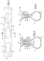
- the rod 5 extends along a main axis A (see FIGS 1 , 4 , 7 , 10 , 14 ).
- the axial direction corresponds to the direction of the main axis A of the rod 5, and a radial direction is a direction perpendicular to axis A and intersecting axis A.
- an axial plane is plane containing axis A
- a radial plane is a plane perpendicular to axis A.
- the adjectives and adverbs "axial”, “axially”, “radial” and “radially” are used relative to the above-mentioned axial and radial directions. Accordingly, the sectional views of FIGS 2, 3 , 5, 6 , 8 , 9 , 11 , 12, 13 and 15 , are radial sectional views.
- the rod 5 has a radial section which is round and constant along the main axis A of the rod 5, and the compression member 14 is separable from the rod 5.
- Each hole 8, 8', 8" has an opening section with an oblong shape extending axially, as shown in FIG 1 , and the compression member 14 is a wedge configured to be inserted into the hole 8.
- the axial length of the compression member 14 is smaller than the axial length of the hole 8 and, preferably, larger than the width of the elongated member 7.
- the radial section of the rod 5 can have other shapes (for example, an oval), may not be constant along its main axis A, and can include varying degrees of curvature.
- the compression member 14 has a tapered tip portion 14b. Once the elongated member 7 is in a desired position, this tip portion 14b of the compression member 14 is inserted by force into the hole 8, and the elongated member 7 is clamped between clamping surfaces 14a, defined by the side faces of the tip portion 14b, and the clamping surfaces 9a defined by the inner surfaces 9 surrounding the hole 8.
- the clamping surfaces 14a of the compression member 14 have a concave profile whereas the clamping surfaces 9a of the of the rod 5 have a convex profile.
- the cooperation between the concave and convex profiles reduces the risk of disengagement of the compression member 14.
- FIG 3 Another example of bone holding device is shown in FIG 3 .
- This example differs from the one of FIG 2 in that the clamping surfaces 14a of the compression member 14 have protrusions 30 (instead of a concave profile) and in that the inner surfaces 9 of the hole 8 have a straight profile (instead of a convex profile). Due to the protrusions 30, the radial section of the tapered tip portion 14b of the compression member 14 has a fir tree shape. The protrusions 30 prevent relative movement between the compression member 14 and the elongated member 7.
- the rod 5 has a varying radial section along its main axis.
- the rod 5 has portions 5' with a larger section and portions 5" with a smaller section. Portions 5' and 5" are alternated in the axial direction.
- Each portion 5' is provided with one holes 8, 8', 8".
- the compression member 14 has a central compression part 14c having a V-shaped profile and being configured to be partially inserted into the hole 8, and two legs 14d extending from said compression part 14c and encircling partially the outline of the radial section of the rod 5, so that the compression member 14 can be clipped onto the rod 5.
- the proximal end of each leg 14 is connected to the central compression part 14c in the vicinity of one opening of the hole 8, then each leg 14 follows the outline of the rod 5, and the distal end of each leg 14 is located in the vicinity of the other opening of the hole 8.
- the first and second portions 7a, 7b of the elongated member 7 are clamped between the clamping surfaces 14a of the compression part 14c and the inner surfaces 9 of the rod 5.
- FIG 6 Another example of bone holding device is shown in FIG 6 . This example differs from that of FIG 5 in that the clamping surfaces 14a of the compression part 14c have protrusions 30.
- the compression member 14 and the rod 5 form one single piece.
- the compression member 14 is a pushed-in external wall 15 of the rod 5 and the hole 8 opens into the side face 5a of the rod 5, on each side of the compression member 14, thereby forming two passages 19 (see FIG 7 ) surrounding the compression member 14.
- Each passage 19 is defined between the compression member 14 and an inner surface 9 of the rod 5.
- the compression member 14 in radial section has a "V" shape.
- the compression member 14 is elastically deformable between an original stable configuration, wherein the arms 15a of the V-shaped compression member 14 are spaced-apart, and an unstable configuration wherein the arms 15a of the "V" shaped compression member 14 are close together.
- the width of each passage 19 is smaller than the thickness of the elongated member 7.
- the elongated member 7 is inserted by force through the passages 19.
- the portions 7a, 7b of the elongated member 7 may have, respectively, stiff tips 17a, 17b.
- the compression member 14 and the rod 5 form one single piece.
- the hole 8 opens into the side face 5a of the rod 5, on each side of the compression member 14, thereby forming two passages 19 surrounding the compression member 14.
- Each passage 19 is defined between the compression member 14 and an inner surface 9 of the rod 5.
- the first and second portions 7a, 7b of the elongated member 7 have protrusions 40 forming folds or ribs on their outer surface. These protrusions 40 are distant from the extremities of the elongated member 7.
- Each portion 7a, 7b of the elongated member 7 is inserted by force through a passage 19.
- the friction between the elongated member 7 and the clamping surfaces 14a, 9a increases until locking of the protrusions 40 in the passage 19 occurs, so these protrusions 40 are clamped between the compression member 14 and the rod 5.
- the protrusions 40 are made from polymeric material such as polyethylene, polyetheretherketone (PEEK), silicon or from metallic material such as, for example, titanium (for example, pure, alloy, beta), stainless steel, cobalt chromium. These protrusions 40 may be added-on pieces encased in the elongated member 7 during its manufacturing process, e.g. during the weaving of the elongated member 7.
- FIGS 10 and 11 Another example of bone holding device is shown in FIGS 10 and 11 .
- the compression member 14 and the rod 5 form one single piece.
- the hole 8 opens into the side face 5a of the rod 5, on each side of the compression member 14, thereby forming two passages 19 (see FIG 10 ) surrounding the compression member 14.
- Each passage 19 is defined between the compression member 14 and an inner surface 9 of the rod 5.
- Each inner surface 9, which delimits the hole 8, is defined on the inner side of an external wall 20 forming part of the rod 5 and having a limited thickness so as to be easily deformed.
- a tool such as pliers (not shown) may be used for deforming the walls 20.
- these walls 20 may have memory shape properties.
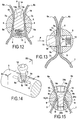
- FIGS 12 and 13 Two other examples of bone holding devices are shown in FIGS 12 and 13 .
- the compression member 14 is spring-mounted to the rod 5 by means of a spring 13 which urges the compression member 14 toward the clamping surfaces 9a of the rod 5, the first and second portions 7a, 7b of the elongated member being clamped between the compression member 14 and the rod 5 when the compression member is urged toward said clamping surfaces 9a.
- the physician or other operative
- the physician need to push in the compression member 14 (see arrow P) in order to pass the first and second portions 7a, 7b through the hole 8.
- the elongated member 7 is "automatically" clamped between the compression member 14 and the rod 5.
- the compression member 14 extends in the same direction as the hole 8.
- the portions 7a, 7b of the elongated member 7 are passed through these passages 19.
- the compression member 14 extends in the a direction substantially perpendicular to that of the hole 8 (called first hole 8) of the rod 5.
- the compression member 14 comprises a second hole 18 extending in the same direction as that of the first hole 8.
- FIGS 14 and 15 Another example of bone holding device is shown in FIGS 14 and 15 .
- the compression member 14 is provided with a thread 14t for rotative engagement with a complementary thread 5t provided on the rod, the first and second portions 7a, 7b of the elongated member 7 being clamped between the compression member 14 and the rod 5 by tightening (by rotating) the compression member 14 relative to the rod 5.
- the compression member 14 is a screw 24 with a head 24a and a shaft 24b.
- the screw head 24a has a profile that allows the screw to be driven.
- the screw shaft 24b is provided with the external thread 14t.
- the screw shaft 24b can engage with a complementary thread 5t of a threaded hole provided in the rod 5.
- the screw 24 extends in substantially the same direction as the hole 8.
- the screw head 24a has a tapered shape, a truncated shape in the example.
- One opening of the hole 8 is funnel-shaped, so that it can receive the screw head 24a. When the screw 24 is rotatably tightened, the screw head 24a bears on the surfaces of the funnel-shaped opening.
- each passage 19 being defined between the compression member 14 and an inner surface 9 of the rod.
- the first and second portions 7a, 7b of the elongated member 7 can be passed through these passages 19 and clamped between the clamping surfaces 14a of the screw head 24a and the clamping surfaces 9a of the rod 5, as shown on FIG 15 .
Abstract
A bone holding device comprising:
- at least one conformable elongated member (7) having a first portion (7a), a second portion (7b) and an intermediate portion (7c) therebetween;
- a rod (5) with at least one hole (8) which opens into at least one of two opposite side faces of the rod, said hole (8) being delimited by inner surfaces (9) of the rod, and
- at least one compression member (14), the compression member and said inner surfaces (9) both defining clamping surfaces (14a, 9a) and cooperating so that the first and second portions (7a, 7b) of the elongated member (7) can be inserted and clamped between said clamping surfaces (14a, 9a).
A method using such a device.
Description
- The present disclosure relates to a device for holding a bone in a desired position and a method using such a device.
- One possible application for the device is holding a bone in a desired position, for example, to aid in the healing of breaks, or holding several bones, notably vertebrae, in relative positions, for example, to correct abnormal curvatures of the spine, which includes scoliosis treatment.
- The spine is formed of superposed vertebrae, from the lumbar vertebrae to the cervical vertebrae, each having an anterior part, which is the vertebral body, and a posterior part, which is the vertebral arch (or neural arch), the anterior and posterior parts enclosing the vertebral foramen. Each vertebral arch is formed by a pair of pedicles and a pair of laminae, and has transverse processes and/or a spinous process (or neural spine) projecting therefrom. The transverse and spinous processes project opposite to the vertebral foramen.
- If the spine of a person has abnormal curvature, the vertebrae are abnormally inclined relative to one another. Typically, the lateral edges or the spinous processes of adjacent vertebrae are closer together or further apart than they should be.
- As a remedy for this situation different kinds of known devices may be used to straighten the spine.
- A first kind of device known in the art is a hook and rod device with hooks that are hooked on the inner surface of the vertebral foramen, and a rod for connecting two or more hooks together. Known examples of hook and rod devices are disclosed, for instance, in the PCT patent application n°
WO 2005/023126 and in US patent n°US 4269178 . However, using hooks can be difficult, especially because their use increases the risk that the physician (or other operative) might contact and potentially damage the spinal cord that extends along the vertebral foramen (which can result in paralysis of the patient). - Another kind of known device is a screw and rod device with screws that are screwed into the vertebrae, and a rod for connecting two or more screws together. A known example of screw and rod device is disclosed, for instance, in European patent n°
EP 1575433B1 . The screws typically are inserted in pairs into the pedicles of a vertebra, on each side of the spinous process, thereby constituting fixing points on the vertebrae for holding the vertebrae. However, in some cases, the pedicles are small or have deteriorated and can be damaged or do not provide sufficient purchase to permanently hold the screw. - Besides, hook and rod devices, as well as screw and rod devices, generally produce a rigid connection between the rod and each vertebra and, thus, between the vertebrae to be held. However, in some cases it is desirable to allow a controlled relative movement between these vertebrae.
- Another kind of known device is disclosed in
WO 2009/047352 . It comprises a rod, a blocking body surrounding the rod and a ligature. When using such a device, the ligature is passed around a bone and through the blocking body, and the rod is loaded into the blocking body. The ends of the ligature are pulled so as to apply tension to the ligature, the ligature and the rod being simultaneously fastened to the blocking body by means of a fastening system comprising a screw or a nut. Portion(s) of the elongated member are clamped between outer face(s) of the rod and inner face(s) of the blocking body. However, this device does not give complete satisfaction because it may be difficult to handle and/or to operate, especially during the fastening step. Moreover, the manufacturing of this device may be expensive, especially due to the number of parts that make up the device. Finally, this device takes up much space, especially due to the blocking body which surrounds the rod. - According to one embodiment of the present disclosure, there is provided a bone holding device comprising:
- at least one conformable elongated member having a first portion, a second portion and an intermediate portion therebetween;
- a rod having at least one hole which opens into at least one of two opposite side faces of the rod, said hole being delimited by inner surfaces of the rod; and
- at least one compression member being adapted for interacting with said inner surfaces to define clamping surfaces, so that the first and second portions of the elongated member can be inserted and clamped between said clamping surfaces.
- Compared to the devices of the prior art, such a bone holding device has a simple structure and a quite limited number of parts and is, therefore, easier to handle by the physician (or other operative) and easier to manufacture. Moreover, since the compression member is at least partly located inside the hole of the rod, it does not take up much space outside of the rod and, thus, the volume of the whole device is limited.
- According to an embodiment, the rod has at least one through hole which opens into two opposite side faces of the rod.
- The elongated member may be made from a conformable material that allows a certain amount of movement so that, even after the physician has pulled and locked in position the portions of the elongated member, the elongated member allows a limited amount of relative movement between the bone and the rod while providing a stabilizing effect. The elongated member may be made from a polymeric material such as, for example, polyester, polyethylene (for example, polyethylene terephthalate or PET), polyetheretherketone (PEEK) or any other material that provides the desired conformability and flexibility.
- According to an embodiment, the compression member is deformable, the first and second portions of the elongated member being clamped between the compression member and the rod by deforming said compression member.
- According to an embodiment, the compression member is elastically deformable, the elongated member being inserted by force between the compression member and the rod, thereby deforming the compression member into an unstable shape. Once insertion forces are no longer applied, the elongated member being in a desired position, the compression member returns to its original stable shape, thereby clamping the elongated member.
- According to another embodiment, the compression member is plastically deformable. In this case, once the elongated member is in a desired position, the compression member is plastically deformed so as to push the elongated member against the rod, thereby clamping the elongated member.
- The compression member and the rod may be two distinct pieces or one single piece. In this latter case, the compression member is made out of the same material as the rod, the compression member and the rod having different mechanic behaviors because of their different shapes and thicknesses.
- According to an embodiment, the compression member comprises a compression part which is configured to be located, at least partially, inside said hole, and at least one leg extending from said compression part and being configured so that the compression member can be clipped onto the rod.
- According to an embodiment, said leg(s) surrounds at least partially the outline of the section of the rod. For instance, the compression member comprises two legs extending from said compression part in opposite directions, each leg surrounding partially the outline of the rod section.
- Thus, before implanting the device, the compression member and the rod may be pre-assembled by clipping, thereby reducing the risk of loosing the compression member and making the device safer and easier to use. Once the device is implanted, the engagement by clipping reduces the risk of disengagement of the compression member.
- According to an embodiment, the compression member is provided with a thread for rotative engagement with a complementary thread provided on the rod, the first and second portions of the elongated member being clamped between the compression member and the rod by tightening the compression member relative to the rod.
- Due to the above-mentioned rotative engagement, the clamping of the elongated member can be easily adjusted as desired. Moreover, the compression member and the rod may be pre-assembled by screwing before implanting the device, thereby reducing the risk of loosing the compression member and making the device safer and easier to use. Once the device is implanted, rotative engagement reduces the risk of disengagement of the compression member.
- According to an embodiment, the compression member is provided with protrusions on its clamping surfaces. Said protrusions may be peripheral ribs or fins jutting out of the lateral faces of the compression member, the compression member having, for instance, a fir tree configuration. Such protrusions penetrate into the elongated member, thereby preventing the elongated member from sliding with respect to the clamping surfaces and/or reducing the risk of disengagement of the compression member.
- According to an embodiment, the compression member is spring-mounted to the rod by means of a spring which urges the compression member toward the clamping surfaces of the rod, the first and second portions of the elongated member being clamped between the compression member and the rod when the compression member is urged toward said clamping surfaces.
- In this embodiment, the physician (or other operative) may need to push in the compression member in order to insert the first and second portions of the elongated member between the compression member and the rod. In this case, by releasing the pressure on the compression member, the elongated member is "automatically" clamped.
- According to an embodiment, the inner surfaces delimiting the hole of the rod are deformable, the first and second portions of the elongated member being clamped between the compression member and the rod by deforming said inner surfaces.
- According to an embodiment, said inner surfaces are plastically deformable. Thus, once the elongated member is in a desired position, said inner surfaces are plastically deformed, typically from the outside of the rod, so as to push the elongated member against the compression member, thereby clamping the elongated member.
- A tool such as pliers may be used for deforming said inner surfaces. Each inner surface may be defined on the inner side of a wall forming part of the rod, this wall having a limited thickness so as to be easily deformed.
- According to an embodiment, the first and second portions of the elongated member are provided with a stiff tip. Such stiff tips make the insertion of the first and second portions into the hole and between the clamping surfaces easier.
- According to an embodiment, the first and second portions of the elongated member are provided with protrusions. Such protrusions increase the friction between the elongated member and said clamping surface, so that the elongated member is held between these surfaces.
- According to an embodiment, the rod comprises at least one portion provided with one hole, said portion(s) having a section which is larger than the average section of the rod. Thus, the loss of mechanical strength due to the presence of the hole is compensated, at least in part, by the section increase.
- According to one embodiment of the present disclosure, there is also provided a method for holding a bone in position, comprising the steps of:
- providing a bone holding device as above-described;
- passing the intermediate portion of a first elongated member around a first bone and the first and second portions of the first elongated member through a first hole of the rod;
- applying tension to the first elongated member by pulling on the ends of the first elongated member;
- fastening the first elongated member to the rod by clamping the portions of the first elongated member between a first compression member and the rod.
- According to an embodiment, the method further comprises the steps of:
- passing the intermediate portion of a second elongated member around a second bone and the first and second portions of the second elongated member through a second hole of said rod;
- applying tension to the second elongated member by pulling on the ends of the second elongated member;
- fastening the second elongated member to said rod by clamping the first and second portions of the second elongated member between a second compression member and the rod.
- Typically, the physician uses a number of elongated members and compression members corresponding to the number of bones to be held, with one rod connecting together the elongated members and, thus, the bones.
- The above method makes it possible to hold two or more bones in a desired relative position.
- Said first and/or second bone may be a vertebra, especially a lamina or a transverse process of a vertebra, and the method may be used for holding two or more vertebrae in a desired relative position, so as to treat abnormal curvature of the spine.
- Such a method has further advantages linked to the use of a bone holding device according to the disclosure. Especially, this method is easy to implement.
- In the drawings, like reference signs generally refer to the same parts throughout the different views. Moreover, parts of different embodiments having the same or analogous function are identified by the same reference sign.
- The drawings are not necessarily to scale, emphasis instead being placed upon illustrating the principles of the invention.
-
FIG 1 is a partial view of a first example of rod. -
FIG 2 is a sectional view of a first example of bone holding device, comprising the rod ofFIG 1 , this rod being sectioned in plane II-II. -
FIG 3 is a sectional view, like that ofFIG 2 , of another example of bone holding device. -
FIG 4 is a partial view of another example of bone holding device. -
FIG 5 is a sectional view of the device ofFIG 4 , in plane V-V. -
FIG 6 is a sectional view, like that ofFIG 4 , of another example of bone holding device. -
FIG 7 is a partial view of another example of bone holding device. -
FIG 8 is a sectional view of the device ofFIG 7 , in plane VIII-VIII. -
FIG 9 is a sectional view, like that ofFIG 8 , of another example of bone holding device. -
FIG 10 is a partial perspective view of another example of bone holding device. -
FIG 11 is a sectional view of the device ofFIG 10 , in plane XI-XI. -
FIG 12 is a sectional view of another example of bone holding device. -
FIG 13 is a sectional view of another example of bone holding device. -
FIG 14 is a partial perspective view of another example of bone holding device. -
FIG 15 is a sectional view of the device ofFIG 14 , in plane XV-XV. -
FIGS 1 to 15 show different examples of bone holding devices according to the present disclosure, each of them comprising: - at least one conformable
elongated member 7 having afirst portion 7a, asecond portion 7b and anintermediate portion 7c therebetween; - a
rod 5 to which the first andsecond portions - at least one
compression member 14. - The
rod 5 comprisesseveral holes rod 5 can include a single hole. Eachhole 8 is a through hole opening into two opposite side faces 5a, 5b of therod 5, i.e. eachhole 8 goes through therod 5, from afirst side face 5a of the rod to asecond side face 5b which is substantially opposed to the first one with respect to the main axis A of therod 5. In other embodiments, the hole may not pass through theentire rod 5. The side faces 5a, 5b are so called in contrast with the end faces (not shown on the drawings) of therod 5, both the side and end faces being outer faces of therod 5. - Each
hole 8 is delimited byinner surfaces 9 of therod 5. Theseinner surfaces 9 and thecompression member 14 both define clampingsurfaces compression member 14 facing the clamping surfaces 9a of theinner surfaces 9, once thecompression member 14 is properly positioned within thehole 8. - The
compression member 14 and theinner surfaces 9 cooperate so that theportions elongated member 7 can be inserted and clamped between the clampingsurfaces - The
compression member 14 may be made from polymeric material such as, for example, polyethylene, polyetheretherketone (PEEK), silicon or from metallic material such as, for example, titanium (for example, pure, alloy, beta), stainless steel, cobalt chromium. - The
rod 5 may be made from polymeric material such as, for example, polyetheretherketone (PEEK) or from metallic material such as, for example, titanium (for example, pure, alloy, beta), stainless steel, cobalt chromium or any other material providing enough stiffness for holding one or several bones in a desired configuration. - In one embodiment, the
elongated member 7 is a tie having a band shape. In other embodiments, theelongate member 7 may be a cord or other shape. It may be made from a polymeric material such as, for example, polyester, polyethylene (for example, PET), polyetheretherketone (PEEK) or any other material that provides the desired conformability and a certain amount of elasticity. For example, it may be made by weaving. - The devices of
FIGS 1 to 15 may be used by a physician, or another operative, as follows: - the
intermediate portion 7c of a firstelongated member 7 is passed around a first bone (not shown) and the first andsecond portions elongated member 7 are passed through afirst hole 8 of therod 5; - tension is applied to the first
elongated member 7 by pulling on itsends - the first
elongated member 7 is fastened to therod 5 by clamping its first andsecond portions first compression member 14 and theinner surfaces 9 of thefirst hole 8. - In one procedure, one of the
ends elongated member 7 may be passed through afirst hole 8 of therod 5, passed around bony anatomy (not shown), and then passed back through thehole 8 of therod 5 for subsequent tensioning and clamping. The ends 6a, 6b may be any portion of theelongated member 7 that extends outside of thehole 8 of therod 5 opposite theintermediate portion 7c of theelongated member 7. - In some cases, for passing the first
elongated member 7 through thehole 8 of therod 5, it may be necessary to use a special tool, such as a needle, having a shape adapted to that of thehole 8. - Also, for applying tension to the first
elongated member 7 and/or for fastening the firstelongated member 7 to therod 5, it may be necessary to use a special tool. - When two bones need to be held in a relative position, the method further comprises the following steps:
- an intermediate portion of a second elongated member (not shown) is passed around a second bone (not shown) and first and second portions of the second elongated member are passed through a second hole 8' (or 8") of said
rod 5; - tension is applied to the second elongated member by pulling on its ends;
- the second elongated member is fastened to said
rod 5 by clamping the first and second portions between a second compression member (not shown) and the inner surfaces 9' of the second hole 8'. - When more than two bones need to be held in a relative position, the above-mentioned steps are repeated, as many elongated members, compression members and holes as necessary being used.
- The number of
holes - In the examples of
FIGS 1 to 15 , therod 5 extends along a main axis A (seeFIGS 1 ,4 ,7 ,10 ,14 ). In the present disclosure, the axial direction corresponds to the direction of the main axis A of therod 5, and a radial direction is a direction perpendicular to axis A and intersecting axis A. Similarly, an axial plane is plane containing axis A, and a radial plane is a plane perpendicular to axis A. Unless specified to the contrary, the adjectives and adverbs "axial", "axially", "radial" and "radially" are used relative to the above-mentioned axial and radial directions. Accordingly, the sectional views ofFIGS 2, 3 ,5, 6 ,8 ,9 ,11 ,12, 13 and 15 , are radial sectional views. - In the example of
FIGS 1 and 2 , therod 5 has a radial section which is round and constant along the main axis A of therod 5, and thecompression member 14 is separable from therod 5. Eachhole FIG 1 , and thecompression member 14 is a wedge configured to be inserted into thehole 8. The axial length of thecompression member 14 is smaller than the axial length of thehole 8 and, preferably, larger than the width of theelongated member 7. In other embodiments, the radial section of therod 5 can have other shapes (for example, an oval), may not be constant along its main axis A, and can include varying degrees of curvature. - As shown in
FIG 2 , in radial section, thecompression member 14 has a taperedtip portion 14b. Once theelongated member 7 is in a desired position, thistip portion 14b of thecompression member 14 is inserted by force into thehole 8, and theelongated member 7 is clamped between clampingsurfaces 14a, defined by the side faces of thetip portion 14b, and the clamping surfaces 9a defined by theinner surfaces 9 surrounding thehole 8. - As shown in
FIG 2 , the clamping surfaces 14a of thecompression member 14 have a concave profile whereas the clamping surfaces 9a of the of therod 5 have a convex profile. The cooperation between the concave and convex profiles reduces the risk of disengagement of thecompression member 14. - Another example of bone holding device is shown in
FIG 3 . This example differs from the one ofFIG 2 in that the clamping surfaces 14a of thecompression member 14 have protrusions 30 (instead of a concave profile) and in that theinner surfaces 9 of thehole 8 have a straight profile (instead of a convex profile). Due to theprotrusions 30, the radial section of the taperedtip portion 14b of thecompression member 14 has a fir tree shape. Theprotrusions 30 prevent relative movement between thecompression member 14 and theelongated member 7. - In the example of
FIGS 4 and 5 , therod 5 has a varying radial section along its main axis. Therod 5 has portions 5' with a larger section andportions 5" with a smaller section.Portions 5' and 5" are alternated in the axial direction. Each portion 5' is provided with oneholes hole 8 is compensated, at least in part, by the section increase, the weight of therod 5 remaining limited. - As shown in
FIG 5 , thecompression member 14 has acentral compression part 14c having a V-shaped profile and being configured to be partially inserted into thehole 8, and twolegs 14d extending from saidcompression part 14c and encircling partially the outline of the radial section of therod 5, so that thecompression member 14 can be clipped onto therod 5. As shown inFIG 5 , in radial section, the proximal end of eachleg 14 is connected to thecentral compression part 14c in the vicinity of one opening of thehole 8, then eachleg 14 follows the outline of therod 5, and the distal end of eachleg 14 is located in the vicinity of the other opening of thehole 8. - The first and
second portions elongated member 7 are clamped between the clamping surfaces 14a of thecompression part 14c and theinner surfaces 9 of therod 5. - Another example of bone holding device is shown in
FIG 6 . This example differs from that ofFIG 5 in that the clamping surfaces 14a of thecompression part 14c have protrusions 30. - In the example of
FIGS 7 and 8 , thecompression member 14 and therod 5 form one single piece. Thecompression member 14 is a pushed-inexternal wall 15 of therod 5 and thehole 8 opens into theside face 5a of therod 5, on each side of thecompression member 14, thereby forming two passages 19 (seeFIG 7 ) surrounding thecompression member 14. Eachpassage 19 is defined between thecompression member 14 and aninner surface 9 of therod 5. - The
compression member 14 in radial section has a "V" shape. Thecompression member 14 is elastically deformable between an original stable configuration, wherein thearms 15a of the V-shapedcompression member 14 are spaced-apart, and an unstable configuration wherein thearms 15a of the "V" shapedcompression member 14 are close together. When thecompression member 14 is in its original stable configuration, the width of eachpassage 19 is smaller than the thickness of theelongated member 7. - The
elongated member 7 is inserted by force through thepassages 19. In order to make the insertion easier, theportions elongated member 7 may have, respectively,stiff tips elongated member 7 being in a desired position, thecompression member 14 returns to its original stable shape, i.e.arms 15a move apart, thereby clamping theelongated member 7 between thearms 15a and therod 5. - In the example of
FIGS 9 , thecompression member 14 and therod 5 form one single piece. Thehole 8 opens into theside face 5a of therod 5, on each side of thecompression member 14, thereby forming twopassages 19 surrounding thecompression member 14. Eachpassage 19 is defined between thecompression member 14 and aninner surface 9 of therod 5. - The first and
second portions elongated member 7 haveprotrusions 40 forming folds or ribs on their outer surface. Theseprotrusions 40 are distant from the extremities of theelongated member 7. - Each
portion elongated member 7 is inserted by force through apassage 19. When theprotrusions 40 enter into thepassage 19, the friction between theelongated member 7 and the clamping surfaces 14a, 9a increases until locking of theprotrusions 40 in thepassage 19 occurs, so theseprotrusions 40 are clamped between thecompression member 14 and therod 5. - For instance, the
protrusions 40 are made from polymeric material such as polyethylene, polyetheretherketone (PEEK), silicon or from metallic material such as, for example, titanium (for example, pure, alloy, beta), stainless steel, cobalt chromium. Theseprotrusions 40 may be added-on pieces encased in theelongated member 7 during its manufacturing process, e.g. during the weaving of theelongated member 7. - Another example of bone holding device is shown in
FIGS 10 and 11 . In this example, thecompression member 14 and therod 5 form one single piece. Thehole 8 opens into theside face 5a of therod 5, on each side of thecompression member 14, thereby forming two passages 19 (seeFIG 10 ) surrounding thecompression member 14. Eachpassage 19 is defined between thecompression member 14 and aninner surface 9 of therod 5. - Each
inner surface 9, which delimits thehole 8, is defined on the inner side of anexternal wall 20 forming part of therod 5 and having a limited thickness so as to be easily deformed. Once theelongated member 7 is in a desired position, thewall 20 is plastically deformed, from the outside of therod 5, so as to push and clamp theelongated member 7 against thecompression member 14. - A tool such as pliers (not shown) may be used for deforming the
walls 20. In order to make the deformation of thewalls 20 easier, thesewalls 20 may have memory shape properties. - Two other examples of bone holding devices are shown in
FIGS 12 and 13 . In both examples, thecompression member 14 is spring-mounted to therod 5 by means of aspring 13 which urges thecompression member 14 toward the clamping surfaces 9a of therod 5, the first andsecond portions compression member 14 and therod 5 when the compression member is urged toward said clampingsurfaces 9a. In both examples, the physician (or other operative) need to push in the compression member 14 (see arrow P) in order to pass the first andsecond portions hole 8. By releasing the pressure on thecompression member 14, theelongated member 7 is "automatically" clamped between thecompression member 14 and therod 5. - In the example of
FIG 12 , thecompression member 14 extends in the same direction as thehole 8. Thus, there exist twopassages 19, on each side of thecompression member 14, eachpassage 19 being defined between thecompression member 14 and aninner surface 9 of the rod. Theportions elongated member 7 are passed through thesepassages 19. - In the example of
FIG 13 , thecompression member 14 extends in the a direction substantially perpendicular to that of the hole 8 (called first hole 8) of therod 5. Thecompression member 14 comprises asecond hole 18 extending in the same direction as that of thefirst hole 8. When thecompression member 14 is pushed in the first andsecond holes second portions elongated member 7 can be passed through theseholes compression member 14 is released, the first andsecond holes elongated member 7 is clamped between the clamping surfaces 14a and 9a. - Another example of bone holding device is shown in
FIGS 14 and 15 . In this example, thecompression member 14 is provided with athread 14t for rotative engagement with acomplementary thread 5t provided on the rod, the first andsecond portions elongated member 7 being clamped between thecompression member 14 and therod 5 by tightening (by rotating) thecompression member 14 relative to therod 5. - More particularly, the
compression member 14 is a screw 24 with ahead 24a and ashaft 24b. Thescrew head 24a has a profile that allows the screw to be driven. Thescrew shaft 24b is provided with theexternal thread 14t. Thescrew shaft 24b can engage with acomplementary thread 5t of a threaded hole provided in therod 5. The screw 24 extends in substantially the same direction as thehole 8. Thescrew head 24a has a tapered shape, a truncated shape in the example. One opening of thehole 8 is funnel-shaped, so that it can receive thescrew head 24a. When the screw 24 is rotatably tightened, thescrew head 24a bears on the surfaces of the funnel-shaped opening. - There exist two
passages 19, on each side of thecompression member 14, eachpassage 19 being defined between thecompression member 14 and aninner surface 9 of the rod. The first andsecond portions elongated member 7 can be passed through thesepassages 19 and clamped between the clamping surfaces 14a of thescrew head 24a and the clamping surfaces 9a of therod 5, as shown onFIG 15 .
Claims (15)
- A bone holding device comprising:- at least one elongated member (7) having a first portion (7a), a second portion (7b) and an intermediate portion (7c) therebetween,- a rod (5) having at least one hole (8) which opens into at least one of two opposite side faces (5a, 5b) of the rod, said hole (8) being delimited by inner surfaces (9) of the rod, and- at least one compression member (14) being adapted for interacting with said inner surfaces (9) to define clamping surfaces (14a, 9a), so that the first and second portions (7a, 7b) of the elongated member (7) can be inserted and clamped between said clamping surfaces (14a, 9a).
- A bone holding device according to claim 1, wherein the compression member (14) and the rod (5) are two distinct pieces, the compression member (14) being moveable relative to the rod, the first and second portions (7a, 7b) of the elongated member (7) being clamped between the compression member (14) and the rod (5) by moving the compression member (14) relative to the rod (5).
- A bone holding device according to claim 2, wherein the compression member (14) is provided with a thread (14t) for rotative engagement with a complementary thread (5t) provided on the rod (5), the first and second portions (7a, 7b) of the elongated member (7) being clamped between the compression member (14) and the rod (5) by tightening the compression member (14) relative to the rod (5).
- A bone holding device according to claim 2, wherein the compression member (14) is spring-mounted to the rod (5) by means of a spring (13) which urges the compression member (14) toward the clamping surfaces (9a) of the rod, the first and second portions (7a, 7b) of the elongated member (7) being clamped between the compression member (14) and the rod (5) when the compression member (14) is urged.
- A bone holding device according to claim 1 or 2, wherein the compression member (14) is deformable, the first and second portions (7a, 7b) of the elongated member (7) being clamped between the compression member (14) and the rod (5) by deforming said compression member.
- A bone holding device according to any one of claims 1, 2 and 5, wherein the compression member (14) comprises :- a compression part (14c) which is configured to be inserted, at least partially, into said hole (8), and- at least one leg (14d) extending from said compression part (14c) and being configured so that the compression member (14) can be clipped onto the rod (5).
- A bone holding device according to claim 1, wherein said inner surfaces (9) are deformable, the first and second portions (7a, 7b) of the elongated member (7) being clamped between the compression member (14) and the rod (5) by deforming said inner surfaces (9).
- A bone holding device according to claim 1, 5 or 7, wherein the compression member (14) and the rod (5) are one single piece.
- A bone holding device according to any one of claims 1 to 8, wherein the first and second portions (7a, 7b) of the elongated member (7) are provided with a stiff tip (17a, 17b).
- A bone holding device according to any one of claims 1 to 9, wherein the compression member (14) is provided with protrusions (30) on its clamping surfaces (14a).
- A bone holding device according to any one of claims 1 to 10, wherein the first and second portions (7a, 7b) of the elongated member (7) are provided with protrusions (40).
- A bone holding device according to any one of claims 1 to 11, wherein the rod (5) comprises at least one portion (5') provided with one hole (8), said portion (5') having a section which is larger than the average section of the rod (5).
- A method for holding a bone in position, comprising the steps of:- providing a bone holding device according to any one of the preceding claims;- passing the intermediate portion (7c) of a first elongated member (7) around a first bone and the first and second portions of the first elongated member (7) through a first hole (8) of the rod (5);- applying tension to the first elongated member (7) by pulling on its ends (6a, 6b);- fastening the first elongated member (7) to the rod (5) by clamping the first and second portions (7a, 7b) of the first elongated member (7) between a first compression member (14) and the rod (5).
- A method according to claim 13, further comprising the steps of:- passing the intermediate portion (7c) of a second elongated member (7) around a second bone and the first and second portions of the second elongated member (7) through a second hole (8') of said rod (5);- applying tension to the second elongated member (7) by pulling on its ends (6a, 6b);- fastening the second elongated member (7) to said rod (5) by clamping the first and second portions of the second elongated member (7) between a second compression member (14) and the rod (5).
- A method according to claim 13 or 14, wherein said first and/or second bone is a vertebra.
Priority Applications (6)
| Application Number | Priority Date | Filing Date | Title |
|---|---|---|---|
| EP09306021A EP2316363A1 (en) | 2009-10-27 | 2009-10-27 | Bone holding device |
| PCT/EP2010/066223 WO2011051316A2 (en) | 2009-10-27 | 2010-10-27 | Bone holding device |
| EP10773050.9A EP2493400B1 (en) | 2009-10-27 | 2010-10-27 | Bone holding device |
| US13/504,230 US9345518B2 (en) | 2009-10-27 | 2010-10-27 | Bone holding device |
| US15/161,626 US9962195B2 (en) | 2009-10-27 | 2016-05-23 | Bone holding device |
| US15/938,807 US20180214188A1 (en) | 2009-10-27 | 2018-03-28 | Bone holding device |
Applications Claiming Priority (1)
| Application Number | Priority Date | Filing Date | Title |
|---|---|---|---|
| EP09306021A EP2316363A1 (en) | 2009-10-27 | 2009-10-27 | Bone holding device |
Publications (1)
| Publication Number | Publication Date |
|---|---|
| EP2316363A1 true EP2316363A1 (en) | 2011-05-04 |
Family
ID=41478763
Family Applications (2)
| Application Number | Title | Priority Date | Filing Date |
|---|---|---|---|
| EP09306021A Withdrawn EP2316363A1 (en) | 2009-10-27 | 2009-10-27 | Bone holding device |
| EP10773050.9A Not-in-force EP2493400B1 (en) | 2009-10-27 | 2010-10-27 | Bone holding device |
Family Applications After (1)
| Application Number | Title | Priority Date | Filing Date |
|---|---|---|---|
| EP10773050.9A Not-in-force EP2493400B1 (en) | 2009-10-27 | 2010-10-27 | Bone holding device |
Country Status (3)
| Country | Link |
|---|---|
| US (3) | US9345518B2 (en) |
| EP (2) | EP2316363A1 (en) |
| WO (1) | WO2011051316A2 (en) |
Cited By (8)
| Publication number | Priority date | Publication date | Assignee | Title |
|---|---|---|---|---|
| RU2474389C1 (en) * | 2011-05-25 | 2013-02-10 | Государственное образовательное учреждение высшего профессионального образования Новгородский государственный университет имени Ярослава Мудрого | Method of temporary rib fixation in programmed rethoracotomy and device for implementing it |
| EP2572662A1 (en) * | 2011-09-23 | 2013-03-27 | Zimmer Spine | Stabilization device for vertebrae |
| EP2777569A1 (en) * | 2013-03-11 | 2014-09-17 | K2M, Inc. | Flexible fastening system |
| FR3031666A1 (en) * | 2015-01-20 | 2016-07-22 | Implanet | DEVICE AND METHOD FOR FASTENING A FLAT STRIP ON A BONE PART. |
| US9757167B2 (en) | 2015-03-11 | 2017-09-12 | K2M, Inc. | Inserter and method for securing an implant to a spinal process with a flexible fastening system |
| US10064656B2 (en) | 2015-02-12 | 2018-09-04 | K2M, Inc. | Spinal fixation construct and methods of use |
| EP3405129A4 (en) * | 2016-01-19 | 2019-09-18 | K2M, Inc. | Spinal correction system and method of use thereof |
| WO2021127300A1 (en) * | 2019-12-18 | 2021-06-24 | Dsm Ip Assets B.V. | Orthopedic screws and prostheses for use with polymer cables |
Families Citing this family (26)
| Publication number | Priority date | Publication date | Assignee | Title |
|---|---|---|---|---|
| EP2047813A1 (en) * | 2007-10-11 | 2009-04-15 | Abbott Spine | Bone fixing system and method of use |
| EP2316363A1 (en) | 2009-10-27 | 2011-05-04 | Zimmer Spine | Bone holding device |
| US9168076B2 (en) | 2011-01-25 | 2015-10-27 | Bridging Medical, Llc | Bone compression screw |
| EP3205299B1 (en) * | 2011-06-29 | 2019-10-30 | Biomet Microfixation, Llc | Locking mechanism to secure ends of an implantable fabric |
| EP2755582B1 (en) | 2011-09-14 | 2023-07-26 | OrthoPediatrics Corp. | Tether clamp and implantation system |
| CN103987327A (en) | 2011-10-05 | 2014-08-13 | 马克·A·多德森 | Modular retractor and related method |
| US9265543B2 (en) * | 2011-12-27 | 2016-02-23 | Pioneer Surgical Technology, Inc. | Bone plate system and method |
| FR2988992B1 (en) * | 2012-04-04 | 2015-03-20 | Medicrea International | MATERIAL OF VERTEBRAL OSTEOSYNTHESIS |
| EP2668921B1 (en) * | 2012-06-01 | 2015-08-12 | Zimmer Spine | Device for fixing a bony structure to a support member |
| US10765465B2 (en) | 2012-11-21 | 2020-09-08 | A&E Advanced Closure Systems, Llc | Tensioning instrument |
| US9561064B2 (en) | 2012-11-21 | 2017-02-07 | Pioneer Surgical Technology, Inc. | Bone plate system and method |
| US20140148854A1 (en) | 2012-11-28 | 2014-05-29 | Zimmer Spine, Inc. | Vertebral fixation system |
| US9820755B2 (en) | 2013-03-15 | 2017-11-21 | Zimmer Biomet CMF and Thoracic, LLC | Sternal closure cerclage, plate implant and instrumentation |
| US10010359B2 (en) | 2013-03-15 | 2018-07-03 | Zimmer Biomet CMF and Thoracic, LLC | Sternal closure cerclage, plate implant and instrumentation |
| WO2014144479A1 (en) | 2013-03-15 | 2014-09-18 | Biomet Microfixation, Llc | Sternal closure cerclage, plate implant and instrumentation |
| US9999454B2 (en) | 2013-12-05 | 2018-06-19 | A&E Advanced Closure Systems, Llc | Bone plate system and method |
| US9402666B2 (en) * | 2014-04-30 | 2016-08-02 | King Faisal Specialist Hospital & Research Centre | Vertebral fixation device |
| US10314635B2 (en) | 2014-05-28 | 2019-06-11 | A&E Advanced Closure Systems, Llc | Tensioning instruments |
| WO2016081528A1 (en) | 2014-11-17 | 2016-05-26 | Bridging Medical, Llc | Bone compression systems |
| US9924976B2 (en) * | 2015-09-24 | 2018-03-27 | Warsaw Orthopedic, Inc. | Spinal implant system and method |
| EP3405131B1 (en) | 2016-01-22 | 2023-07-19 | A&E Advanced Closure Systems, LLC | Bone plate having a connector and a connector for a surgical loop |
| WO2018022769A1 (en) | 2016-07-26 | 2018-02-01 | Band-Lok, Llc | Orthopedic tethered implants and system |
| US10485600B2 (en) | 2016-07-29 | 2019-11-26 | A&E Advanced Closure Systems, Llc | Surgical cable tensioner |
| US11071569B2 (en) | 2017-08-10 | 2021-07-27 | Ortho Development Corporation | Nesting tether clamping assemblies and related methods and apparatus |
| US11051857B2 (en) * | 2017-08-10 | 2021-07-06 | Ortho Development Corporation | Tether clamping assemblies and related methods and apparatus |
| US11771472B2 (en) * | 2019-10-29 | 2023-10-03 | Globus Medical, Inc. | Sublaminar band clamp |
Citations (9)
| Publication number | Priority date | Publication date | Assignee | Title |
|---|---|---|---|---|
| US4269178A (en) | 1979-06-04 | 1981-05-26 | Keene James S | Hook assembly for engaging a spinal column |
| WO2001054599A1 (en) * | 2000-01-31 | 2001-08-02 | Sven Olerud | Locking device and method for using this device |
| US6277120B1 (en) * | 2000-09-20 | 2001-08-21 | Kevin Jon Lawson | Cable-anchor system for spinal fixation |
| WO2002087415A2 (en) * | 2001-04-26 | 2002-11-07 | Poly-4 Medical, Inc. | Method of applying an active compressive force continuously across a fracture |
| WO2005023126A1 (en) | 2003-09-04 | 2005-03-17 | Abbott Spine | Spinal implant |
| EP1575433B1 (en) | 2002-10-07 | 2008-11-05 | Abbott Spine | Plate fixing system |
| WO2009047352A1 (en) | 2007-10-11 | 2009-04-16 | Zimmer Spine | Bone fixing system and method of use |
| EP2052689A1 (en) * | 2007-10-23 | 2009-04-29 | Abbott Spine | Fixing devices and stabilization systems using said fixing devices |
| US20090248077A1 (en) * | 2008-03-31 | 2009-10-01 | Derrick William Johns | Hybrid dynamic stabilization |
Family Cites Families (38)
| Publication number | Priority date | Publication date | Assignee | Title |
|---|---|---|---|---|
| US2049361A (en) | 1934-10-27 | 1936-07-28 | Ericsson Ernst Axel Johan | Wire or ribbon tightening apparatus |
| US4570618A (en) | 1983-11-23 | 1986-02-18 | Henry Ford Hospital | Intervertebral body wire stabilization |
| USRE36221E (en) | 1989-02-03 | 1999-06-01 | Breard; Francis Henri | Flexible inter-vertebral stabilizer as well as process and apparatus for determining or verifying its tension before installation on the spinal column |
| US5030220A (en) | 1990-03-29 | 1991-07-09 | Advanced Spine Fixation Systems Incorporated | Spine fixation system |
| US5304178A (en) | 1992-05-29 | 1994-04-19 | Acromed Corporation | Sublaminar wire |
| US5383905A (en) * | 1992-10-09 | 1995-01-24 | United States Surgical Corporation | Suture loop locking device |
| US5356412A (en) * | 1992-10-09 | 1994-10-18 | United States Surgical Corporation | Sternum buckle with rotational engagement and method of closure |
| US5810825A (en) * | 1995-06-01 | 1998-09-22 | Huebner; Randall J. | Surgical wire clamp |
| US6017347A (en) * | 1995-06-01 | 2000-01-25 | Acumed, Inc. | Wire clamp assembly |
| JP2987037B2 (en) * | 1993-08-09 | 1999-12-06 | 喜十郎 早野 | Wire fastener |
| US5415658A (en) * | 1993-12-14 | 1995-05-16 | Pioneer Laboratories, Inc. | Surgical cable loop connector |
| WO1995022294A1 (en) | 1994-02-17 | 1995-08-24 | Surgical Accessories, Inc. | Fastener and tensioner for bone securing cable |
| FR2761590B1 (en) | 1997-04-04 | 1999-08-20 | Stryker France Sa | DEVICE FOR OSTEOSYNTHESIS OF THE RACHIS WITH ATTACHMENT OF DEAXED INTERVERTEBRAL ROD |
| US6053921A (en) | 1997-08-26 | 2000-04-25 | Spinal Concepts, Inc. | Surgical cable system and method |
| US5964769A (en) | 1997-08-26 | 1999-10-12 | Spinal Concepts, Inc. | Surgical cable system and method |
| US6179838B1 (en) | 1998-02-24 | 2001-01-30 | Daniel Fiz | Bone fixation arrangements and method |
| US6086590A (en) | 1999-02-02 | 2000-07-11 | Pioneer Laboratories, Inc. | Cable connector for orthopaedic rod |
| US6299613B1 (en) | 1999-04-23 | 2001-10-09 | Sdgi Holdings, Inc. | Method for the correction of spinal deformities through vertebral body tethering without fusion |
| US6514255B1 (en) | 2000-02-25 | 2003-02-04 | Bret Ferree | Sublaminar spinal fixation apparatus |
| US6605091B1 (en) | 2000-06-30 | 2003-08-12 | Pioneer Laboratories, Inc. | Surgical cable assembly and method |
| GB0018826D0 (en) | 2000-08-02 | 2000-09-20 | Depuy Int Ltd | Improvements in and relating to fixings |
| US6524315B1 (en) | 2000-08-08 | 2003-02-25 | Depuy Acromed, Inc. | Orthopaedic rod/plate locking mechanism |
| EP1502552A3 (en) * | 2000-10-24 | 2005-03-16 | The Spineology Group, LLC | Tension band clip |
| EP1205152B1 (en) | 2000-11-10 | 2004-09-29 | Lafitt, S.A. | Spinal column deformity correction device |
| US6960213B2 (en) * | 2001-05-23 | 2005-11-01 | Medicinelodge, Inc. | Apparatus and method for orthopedic fixation |
| US6695852B2 (en) | 2001-10-31 | 2004-02-24 | Spineology, Inc. | Tension tools for tension band clip |
| FR2842724B1 (en) | 2002-07-23 | 2005-05-27 | Spine Next Sa | VERTEBRAL FASTENING SYSTEM |
| US7250054B2 (en) * | 2002-08-28 | 2007-07-31 | Smith & Nephew, Inc. | Systems, methods, and apparatuses for clamping and reclamping an orthopedic surgical cable |
| FR2890850B1 (en) | 2005-09-20 | 2009-04-17 | Abbott Spine Sa | VERTEBRAL FASTENING SYSTEM |
| FR2890851B1 (en) | 2005-09-21 | 2008-06-20 | Abbott Spine Sa | ANCILLARY TO TENSION A FLEXIBLE LINK. |
| US8470002B2 (en) * | 2007-02-20 | 2013-06-25 | Warsaw Orthopedic, Inc. | Resorbable release mechanism for a surgical tether and methods of use |
| US8142434B2 (en) * | 2007-10-17 | 2012-03-27 | Stryker Trauma Gmbh | Cam-locking of cable for fracture plate |
| US8128635B2 (en) | 2007-10-23 | 2012-03-06 | Zimmer Spine S.A.S. | Bone fixation tensioning tool and method |
| US8617214B2 (en) | 2008-01-07 | 2013-12-31 | Mmsn Limited Partnership | Spinal tension band |
| FR2931654B1 (en) | 2008-05-27 | 2011-12-16 | Medicrea International | MATERIAL OF VERTEBRAL OSTEOSYNTHESIS |
| EP2279707A1 (en) | 2009-07-31 | 2011-02-02 | Zimmer Spine | Bone fixing system |
| EP2316363A1 (en) | 2009-10-27 | 2011-05-04 | Zimmer Spine | Bone holding device |
| US20110301644A1 (en) | 2010-06-08 | 2011-12-08 | Zimmer Spine | Spinal stabilization system |
-
2009
- 2009-10-27 EP EP09306021A patent/EP2316363A1/en not_active Withdrawn
-
2010
- 2010-10-27 EP EP10773050.9A patent/EP2493400B1/en not_active Not-in-force
- 2010-10-27 US US13/504,230 patent/US9345518B2/en active Active
- 2010-10-27 WO PCT/EP2010/066223 patent/WO2011051316A2/en active Application Filing
-
2016
- 2016-05-23 US US15/161,626 patent/US9962195B2/en active Active
-
2018
- 2018-03-28 US US15/938,807 patent/US20180214188A1/en not_active Abandoned
Patent Citations (9)
| Publication number | Priority date | Publication date | Assignee | Title |
|---|---|---|---|---|
| US4269178A (en) | 1979-06-04 | 1981-05-26 | Keene James S | Hook assembly for engaging a spinal column |
| WO2001054599A1 (en) * | 2000-01-31 | 2001-08-02 | Sven Olerud | Locking device and method for using this device |
| US6277120B1 (en) * | 2000-09-20 | 2001-08-21 | Kevin Jon Lawson | Cable-anchor system for spinal fixation |
| WO2002087415A2 (en) * | 2001-04-26 | 2002-11-07 | Poly-4 Medical, Inc. | Method of applying an active compressive force continuously across a fracture |
| EP1575433B1 (en) | 2002-10-07 | 2008-11-05 | Abbott Spine | Plate fixing system |
| WO2005023126A1 (en) | 2003-09-04 | 2005-03-17 | Abbott Spine | Spinal implant |
| WO2009047352A1 (en) | 2007-10-11 | 2009-04-16 | Zimmer Spine | Bone fixing system and method of use |
| EP2052689A1 (en) * | 2007-10-23 | 2009-04-29 | Abbott Spine | Fixing devices and stabilization systems using said fixing devices |
| US20090248077A1 (en) * | 2008-03-31 | 2009-10-01 | Derrick William Johns | Hybrid dynamic stabilization |
Cited By (21)
| Publication number | Priority date | Publication date | Assignee | Title |
|---|---|---|---|---|
| RU2474389C1 (en) * | 2011-05-25 | 2013-02-10 | Государственное образовательное учреждение высшего профессионального образования Новгородский государственный университет имени Ярослава Мудрого | Method of temporary rib fixation in programmed rethoracotomy and device for implementing it |
| EP2572662A1 (en) * | 2011-09-23 | 2013-03-27 | Zimmer Spine | Stabilization device for vertebrae |
| US9675386B2 (en) | 2013-03-11 | 2017-06-13 | K2M, Inc. | Flexible fastening system |
| EP2777569A1 (en) * | 2013-03-11 | 2014-09-17 | K2M, Inc. | Flexible fastening system |
| US11246630B2 (en) | 2013-03-11 | 2022-02-15 | K2M, Inc. | Flexible fastening system |
| AU2016210050C1 (en) * | 2015-01-20 | 2021-01-14 | Implanet | Device for attaching a flat band on a bone part |
| AU2016210050B2 (en) * | 2015-01-20 | 2020-09-03 | Implanet | Device for attaching a flat band on a bone part |
| JP2018501914A (en) * | 2015-01-20 | 2018-01-25 | アンプラネ・ソシエテ・アノニムImplanet,Societe Anonyme | Tools for attaching to a flat band on the bone |
| FR3031666A1 (en) * | 2015-01-20 | 2016-07-22 | Implanet | DEVICE AND METHOD FOR FASTENING A FLAT STRIP ON A BONE PART. |
| US11160584B2 (en) | 2015-01-20 | 2021-11-02 | Implanet | Device for attaching a flat band on a bone part |
| WO2016116692A1 (en) * | 2015-01-20 | 2016-07-28 | Implanet | Device for attaching a flat band on a bone part |
| US10433879B2 (en) | 2015-01-20 | 2019-10-08 | Implanet | Device for attaching a flat band on a bone part |
| US10064656B2 (en) | 2015-02-12 | 2018-09-04 | K2M, Inc. | Spinal fixation construct and methods of use |
| US10582953B2 (en) | 2015-02-12 | 2020-03-10 | K2M, Inc. | Spinal fixation construct and methods of use |
| US11672567B2 (en) | 2015-02-12 | 2023-06-13 | K2M, Inc. | Spinal fixation construct and methods of use |
| US10667847B2 (en) | 2015-03-11 | 2020-06-02 | K2M, Inc. | Inserter and method for securing an implant to a spinal process with a flexible fastening system |
| US9757167B2 (en) | 2015-03-11 | 2017-09-12 | K2M, Inc. | Inserter and method for securing an implant to a spinal process with a flexible fastening system |
| US9999450B2 (en) | 2015-03-11 | 2018-06-19 | K2M, Inc. | Inserter and method for securing an implant to a spinal process with a flexible fastening system |
| US11896269B2 (en) | 2015-03-11 | 2024-02-13 | K2M, Inc. | Inserter and method for securing an implant to a spinal process with a flexible fastening system |
| EP3405129A4 (en) * | 2016-01-19 | 2019-09-18 | K2M, Inc. | Spinal correction system and method of use thereof |
| WO2021127300A1 (en) * | 2019-12-18 | 2021-06-24 | Dsm Ip Assets B.V. | Orthopedic screws and prostheses for use with polymer cables |
Also Published As
| Publication number | Publication date |
|---|---|
| US20180214188A1 (en) | 2018-08-02 |
| US9345518B2 (en) | 2016-05-24 |
| US9962195B2 (en) | 2018-05-08 |
| EP2493400A2 (en) | 2012-09-05 |
| WO2011051316A3 (en) | 2011-06-30 |
| US20160324548A1 (en) | 2016-11-10 |
| WO2011051316A2 (en) | 2011-05-05 |
| EP2493400B1 (en) | 2015-07-08 |
| US20120303065A1 (en) | 2012-11-29 |
Similar Documents
| Publication | Publication Date | Title |
|---|---|---|
| US9962195B2 (en) | Bone holding device | |
| US10631898B2 (en) | Spinal stabilization system with rigid and flexible elements | |
| US8940019B2 (en) | Bone tissue fixation device and method | |
| US6132430A (en) | Spinal fixation system | |
| US20170252036A1 (en) | Devices for generating and applying compression within a body | |
| US8936625B2 (en) | Device for fixing a bony structure to a support member | |
| US20080161857A1 (en) | Spinal stabilization system with flexible guides | |
| EP2460482A1 (en) | Rod holding device | |
| EP2762095B1 (en) | Device for fixing a bony structure to a support member | |
| US10722229B2 (en) | Suture crimp plate | |
| EP2063794B1 (en) | Multiple rod system with elastic rod-containing means |
Legal Events
| Date | Code | Title | Description |
|---|---|---|---|
| PUAI | Public reference made under article 153(3) epc to a published international application that has entered the european phase |
Free format text: ORIGINAL CODE: 0009012 |
|
| AK | Designated contracting states |
Kind code of ref document: A1 Designated state(s): AT BE BG CH CY CZ DE DK EE ES FI FR GB GR HR HU IE IS IT LI LT LU LV MC MK MT NL NO PL PT RO SE SI SK SM TR |
|
| AX | Request for extension of the european patent |
Extension state: AL BA RS |
|
| STAA | Information on the status of an ep patent application or granted ep patent |
Free format text: STATUS: THE APPLICATION IS DEEMED TO BE WITHDRAWN |
|
| 18D | Application deemed to be withdrawn |
Effective date: 20111105 |