EP2330778A2 - Method and system for controlling access to a wireless communication medium - Google Patents
Method and system for controlling access to a wireless communication medium Download PDFInfo
- Publication number
- EP2330778A2 EP2330778A2 EP11159124A EP11159124A EP2330778A2 EP 2330778 A2 EP2330778 A2 EP 2330778A2 EP 11159124 A EP11159124 A EP 11159124A EP 11159124 A EP11159124 A EP 11159124A EP 2330778 A2 EP2330778 A2 EP 2330778A2
- Authority
- EP
- European Patent Office
- Prior art keywords
- sta
- resource allocation
- information
- beacon
- ieee
- Prior art date
- Legal status (The legal status is an assumption and is not a legal conclusion. Google has not performed a legal analysis and makes no representation as to the accuracy of the status listed.)
- Withdrawn
Links
Images


Classifications
-
- H—ELECTRICITY
- H04—ELECTRIC COMMUNICATION TECHNIQUE
- H04B—TRANSMISSION
- H04B7/00—Radio transmission systems, i.e. using radiation field
- H04B7/24—Radio transmission systems, i.e. using radiation field for communication between two or more posts
- H04B7/26—Radio transmission systems, i.e. using radiation field for communication between two or more posts at least one of which is mobile
- H04B7/2612—Arrangements for wireless medium access control, e.g. by allocating physical layer transmission capacity
-
- H—ELECTRICITY
- H04—ELECTRIC COMMUNICATION TECHNIQUE
- H04W—WIRELESS COMMUNICATION NETWORKS
- H04W74/00—Wireless channel access, e.g. scheduled or random access
- H04W74/08—Non-scheduled or contention based access, e.g. random access, ALOHA, CSMA [Carrier Sense Multiple Access]
- H04W74/0808—Non-scheduled or contention based access, e.g. random access, ALOHA, CSMA [Carrier Sense Multiple Access] using carrier sensing, e.g. as in CSMA
- H04W74/0816—Non-scheduled or contention based access, e.g. random access, ALOHA, CSMA [Carrier Sense Multiple Access] using carrier sensing, e.g. as in CSMA carrier sensing with collision avoidance
-
- H—ELECTRICITY
- H04—ELECTRIC COMMUNICATION TECHNIQUE
- H04B—TRANSMISSION
- H04B1/00—Details of transmission systems, not covered by a single one of groups H04B3/00 - H04B13/00; Details of transmission systems not characterised by the medium used for transmission
- H04B1/69—Spread spectrum techniques
- H04B1/707—Spread spectrum techniques using direct sequence modulation
- H04B1/7097—Interference-related aspects
- H04B1/711—Interference-related aspects the interference being multi-path interference
- H04B1/7115—Constructive combining of multi-path signals, i.e. RAKE receivers
-
- H—ELECTRICITY
- H04—ELECTRIC COMMUNICATION TECHNIQUE
- H04B—TRANSMISSION
- H04B7/00—Radio transmission systems, i.e. using radiation field
- H04B7/02—Diversity systems; Multi-antenna system, i.e. transmission or reception using multiple antennas
-
- H—ELECTRICITY
- H04—ELECTRIC COMMUNICATION TECHNIQUE
- H04B—TRANSMISSION
- H04B7/00—Radio transmission systems, i.e. using radiation field
- H04B7/02—Diversity systems; Multi-antenna system, i.e. transmission or reception using multiple antennas
- H04B7/04—Diversity systems; Multi-antenna system, i.e. transmission or reception using multiple antennas using two or more spaced independent antennas
- H04B7/0413—MIMO systems
-
- H—ELECTRICITY
- H04—ELECTRIC COMMUNICATION TECHNIQUE
- H04W—WIRELESS COMMUNICATION NETWORKS
- H04W48/00—Access restriction; Network selection; Access point selection
- H04W48/08—Access restriction or access information delivery, e.g. discovery data delivery
- H04W48/10—Access restriction or access information delivery, e.g. discovery data delivery using broadcasted information
-
- H—ELECTRICITY
- H04—ELECTRIC COMMUNICATION TECHNIQUE
- H04W—WIRELESS COMMUNICATION NETWORKS
- H04W72/00—Local resource management
- H04W72/04—Wireless resource allocation
- H04W72/044—Wireless resource allocation based on the type of the allocated resource
- H04W72/0446—Resources in time domain, e.g. slots or frames
-
- H—ELECTRICITY
- H04—ELECTRIC COMMUNICATION TECHNIQUE
- H04W—WIRELESS COMMUNICATION NETWORKS
- H04W72/00—Local resource management
- H04W72/20—Control channels or signalling for resource management
-
- H—ELECTRICITY
- H04—ELECTRIC COMMUNICATION TECHNIQUE
- H04W—WIRELESS COMMUNICATION NETWORKS
- H04W72/00—Local resource management
- H04W72/30—Resource management for broadcast services
-
- H—ELECTRICITY
- H04—ELECTRIC COMMUNICATION TECHNIQUE
- H04W—WIRELESS COMMUNICATION NETWORKS
- H04W74/00—Wireless channel access, e.g. scheduled or random access
- H04W74/08—Non-scheduled or contention based access, e.g. random access, ALOHA, CSMA [Carrier Sense Multiple Access]
-
- H—ELECTRICITY
- H04—ELECTRIC COMMUNICATION TECHNIQUE
- H04W—WIRELESS COMMUNICATION NETWORKS
- H04W84/00—Network topologies
- H04W84/02—Hierarchically pre-organised networks, e.g. paging networks, cellular networks, WLAN [Wireless Local Area Network] or WLL [Wireless Local Loop]
- H04W84/10—Small scale networks; Flat hierarchical networks
- H04W84/12—WLAN [Wireless Local Area Networks]
-
- H—ELECTRICITY
- H04—ELECTRIC COMMUNICATION TECHNIQUE
- H04W—WIRELESS COMMUNICATION NETWORKS
- H04W88/00—Devices specially adapted for wireless communication networks, e.g. terminals, base stations or access point devices
- H04W88/08—Access point devices
-
- Y—GENERAL TAGGING OF NEW TECHNOLOGICAL DEVELOPMENTS; GENERAL TAGGING OF CROSS-SECTIONAL TECHNOLOGIES SPANNING OVER SEVERAL SECTIONS OF THE IPC; TECHNICAL SUBJECTS COVERED BY FORMER USPC CROSS-REFERENCE ART COLLECTIONS [XRACs] AND DIGESTS
- Y02—TECHNOLOGIES OR APPLICATIONS FOR MITIGATION OR ADAPTATION AGAINST CLIMATE CHANGE
- Y02D—CLIMATE CHANGE MITIGATION TECHNOLOGIES IN INFORMATION AND COMMUNICATION TECHNOLOGIES [ICT], I.E. INFORMATION AND COMMUNICATION TECHNOLOGIES AIMING AT THE REDUCTION OF THEIR OWN ENERGY USE
- Y02D30/00—Reducing energy consumption in communication networks
- Y02D30/70—Reducing energy consumption in communication networks in wireless communication networks
Definitions
- the present invention is related to a wireless communication system. More particularly, the present invention is related to a method and system for controlling access to a medium in a wireless communication system.
- the IEEE 802.11 working group has been set up to develop a new wireless standard with a data rate in excess of 200 Mbps to deliver high throughput data, such as high definition television (HDTV) and streaming video.
- high throughput data such as high definition television (HDTV) and streaming video.
- the theoretical maximum throughput of existing standards IEEE 802.11a and IEEE 802.11g is around 54 Mbps, and the highest usable throughput is around 25 Mbps.
- MAC medium access control
- the present invention is related to a method and system for controlling access to a medium in a wireless communication system.
- a MAC architecture builds upon the existing IEEE 802.11 MAC architecture and its IEEE 802.11e extensions to provide higher performance.
- a superframe structure is defined in time domain to include a contention free period which has at least one scheduled resource allocation (SRA), at least one management SRA (MSRA) and a contention period.
- An extended beacon (EB) including information about the SRA and MSRA is transmitted for.
- the MAC architecture reduces station battery consumption, supports higher throughput for non-real time (NRT) traffic and is more efficient for real time (RT) traffic than IEEE 802.11e while maintaining full compatibility.
- the present invention reduces station (STA) battery consumption, supports higher throughput for non-real time (NRT) traffic and is more efficient for real time (RT) traffic than required by IEEE 802.11e while maintaining full compatibility.
- the present invention eliminates a hidden node problem.
- the present invention provides higher performance for NRT services, better stability and a higher number of users or a higher throughput than required by IEEE 802.11e on enhanced distributed channel access (EDCA) for NRT services, such as a file transfer protocol (FTP) or web browsing under similar latency requirements, and corrects the IEEE 802.11e unfairness towards access point (AP) transmissions.
- EDCA enhanced distributed channel access
- the present invention provides higher performance for RT services while guaranteeing quality of service (QoS), reduced STA power consumption, higher MAC efficiency and throughput for all RT applications, lower delay jitter compared to IEEE 802.11e EDCA, higher MAC efficiency for voice over Internet protocol (VoIP) applications with similar delay jitter compared to IEEE 802.11e hybrid coordination function (HCF) controlled channel access (HCCA).
- QoS quality of service
- STA reduced STA power consumption
- higher MAC efficiency and throughput for all RT applications
- lower delay jitter compared to IEEE 802.11e EDCA higher MAC efficiency for voice over Internet protocol (VoIP) applications with similar delay jitter compared to IEEE 802.11e hybrid coordination function (HCF) controlled channel access (HCCA).
- HCF hybrid coordination function
- the present invention provides backward compatibility with IEEE 802.11 MAC and its IEEE 802.11e extensions, as well as with IEEE 802.11k.
- the present invention supports efficient physical (PHY) operation through orderly back-and-forth transmissions that enable the timely reception of channel quality information (CQI) used to determine coding and modulation rates, the use of channel reciprocity or, if necessary, reception of channel state information (CSI) which may be used to optimize transmitter operation, support of hybrid automatic repeat request (ARQ), and enhanced frequency hopping (optional).
- CQI channel quality information
- CSI channel state information
- the present invention incorporates a flexible design which supports different types of PHY interfaces including, but not limited to, multiple input multiple output (MIMO) and forward error correction (FEC) coding techniques, orthogonal frequency division multiple access (OFDMA) operation, and both a 20MHz and 40MHz high throughput (HT) STA in the same superframe, which is extendable to other bandwidths if necessary.
- MIMO multiple input multiple output
- FEC forward error correction
- OFDMA orthogonal frequency division multiple access
- HT high throughput
- the present invention provides enhanced peer-to-peer direct transfer of data under the control of an AP and support of relay operation to extend service area coverage and rates.
- FIG. 1 is a block diagram of MAC architecture in accordance with the present invention.
- Figure 2 is a block diagram of a superframe structure with legacy operation in accordance with the present invention.
- Figure 3 is a block diagram of a superframe structure without legacy operation in accordance with the present invention.
- Figure 4 is a block diagram illustrating a flexible superframe structure in accordance with the present invention.
- Figure 5 is a diagram illustrating slotted Aloha operation in MSRA
- FIGS. 6 and 7 are block diagrams of exemplary frame exchange sequences with and without ACK, respectively, in accordance with the present invention.
- Figure 8 is a diagram of beacon and EB transmission in accordance with the present invention.
- FIG. 9 is a block diagram of an IE for frequency hopping in accordance with the present invention.
- FIG. 10 is a block diagram of a resource allocation request (RAR) frame in accordance with the present invention.
- FIG. 11 is a block diagram of a frame body of the RAR frame in accordance with the present invention.
- FIG. 12 is a block diagram of each RAR block in accordance with the present invention.
- Figure 13 is a block diagram of a resource allocation response frame in accordance with the present invention.
- Figure 14 is a block diagram of a frame body of the resource allocation response frame in accordance with the present invention.
- FIG. 15 is a block diagram of a general management frame in accordance with the present invention.
- Figure 16 is a block diagram of a frame body of the management frame in accordance with the present invention.
- FIG. 17 is a block diagram of an OFDM MIMO Parameter Set element in accordance with the present invention.
- Figure 18 is a block diagram of a CP Access element in accordance with the present invention.
- Figure 19 is a block diagram of an EB element in accordance with the present invention.
- FIG. 20 is a block diagram of an STA Schedule element in accordance with the present invention.
- FIG. 21 is a block diagram of an STA Block IE in accordance with the present invention.
- FIG. 22 is a block diagram of an MSRA schedule element in accordance with the present invention.
- FIG. 23 is a block diagram of an MSRA Block element in accordance with the present invention.
- Figure 24 is a block diagram of an ORA Schedule element in accordance with the present invention.
- Figure 25 is a block diagram of each ORA Block IE in accordance with the present invention.
- FIG. 26 is a block diagram of an RAR Specification IE in accordance with the present invention.
- FIG. 27 is a block diagram of a Resource Allocation Notification IE in accordance with the present invention.
- Figure 28 is a block diagram of a superframe structure for simulation
- Figure 29 is a diagram of simulation results for throughput comparison
- Figure 30 is a diagram of simulation results for average delay
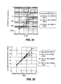
- Figure 31 is a diagram of simulation results for average delay vs. application data rate for eight (8) users
- Figure 32 is a diagram of simulation results for average system throughput vs. application data rate for eight (8) users;
- FIG. 33 is a block diagram of direct link protocol (DLP) signaling in accordance with the present invention.
- DLP direct link protocol
- Figure 34 is a block diagram illustrating message exchange for DLP setup in accordance with the present invention.
- Figure 35 is a diagram showing slotted Aloha operation with collective ACK in MRAP in accordance with the present invention.
- Figure 36 is a diagram showing slotted Aloha operation with immediate ACK in MRAP in accordance with the present invention.
- Figure 37 is a flow diagram of a process for SRA assignment in accordance with the present invention.
- STA includes but is not limited to a user equipment, a wireless transmit/receive unit (WTRU), a fixed or mobile subscriber unit, a pager, or any other type of device capable of operating in a wireless environment.
- WTRU wireless transmit/receive unit
- AP includes but is not limited to a base station, a Node-B, a site controller or any other type of interfacing device in a wireless environment.
- STA refers to a STA configured to support IEEE 802.11n and the terminology “legacy STA” refers to a STA configured to support IEEE 802.11 or IEEE 802.11e.
- AP means any AP that is compliant with the proposed IEEE 802.11n standard.
- STA (or interchangeably IEEE 802.11n STA, high throughput (HT) STA), means any STA that is compliant with the proposed IEEE 802.11n standard.
- Legacy AP means any AP that is complaint with IEEE 802.11 standards predating the IEEE 802.11n standard and therefore does not support the proposed IEEE 802.11n standard.
- Legacy STA includes any STA that is complaint with IEEE 802.11 standards predating the proposed IEEE 802.11n standard and therefore does not support the proposed IEEE 802.11n standard.
- the MAC in accordance with the present invention builds upon the existing IEEE 802.11 MAC architecture and its IEEE 802.11e extensions to provide higher performance for networks which include IEEE 802.11n compliant AP and STAs.
- the system in accordance with the present invention reduces station battery consumption, supports higher throughput for NRT traffic and is more efficient for RT traffic than IEEE 802.11e while maintaining full compatibility, supporting both legacy and high throughput STA at the same time.
- the present invention provides MAC architecture and procedures supporting a variety of physical layer interfaces that may be optimized under the current IEEE 802.11 WLAN service requirements and deployment scenario assumptions.
- a superframe is partitioned between HT period(s) used for IEEE 802.11n access and an optional legacy period used for IEEE 802.11 and IEEE 802.11e access.
- Both RT and NRT services are provided to STA during the IEEE 802.11n period of the super frame using different methods. NRT operation is typified by unpredictable and widely varying data rates with no formal latency requirements.
- Downlink (AP ⁇ STA) data transfers are done at the discretion of the controller, which will generally (but not necessarily) be implemented in the AP. No contention can happen during this time, either from legacy or HT STA. Acknowledgement and feedback packets are regularly transmitted in the reverse direction (uplink, or STA ⁇ AP) after single or multiple packets, depending on conditions and as has been negotiated between the nodes and can be exploited to optimize physical layer performance.
- uplink or STA ⁇ AP
- the mechanism is flexible enough to allow the use of sophisticated scheduling algorithms which may take into account buffer occupancy as well as channel conditions to further enhance system performance. This operation takes place during Scheduled Resource Allocation (SRA) periods in the superframe.
- SRA Scheduled Resource Allocation
- Uplink (STA ⁇ AP) data transfers are accomplished via a slotted Aloha bandwidth request, shortly after followed by a response indicating permission to transmit data.
- acknowledgement and feedback packets are regularly transmitted in the reverse direction after single or multiple packets, depending on conditions and as has been negotiated between the nodes.
- the requests are sent during a management SRA (MSRA) while data transfers are performed during an SRA.
- MSRA management SRA
- the usage of short packets in a slotted Aloha mode increases throughput and stability at high loads and eliminates the hidden node problem as STAs are not required to sense the medium for contention.
- the mechanism is flexible enough to allow the use of sophisticated scheduling algorithms which may take into account buffer occupancy as well as channel conditions to further enhance system performance. Small packets used for management and control purposes, (e.g. in order to set up RT operation), may also be exchanged at this time.
- RT operation is typified by predictable data rates.
- the resources are indicated to each user by an extended beacon (EB) transmitted once or several times per superframe.
- EB extended beacon
- STAs are required to listen only a small fraction of the time which reduces the STA power consumption requirements.
- acknowledgement and feedback packets are regularly transmitted in the reverse direction after single or multiple packets, and can be exploited to optimize physical layer performance.
- NRT scheduling can consider both traffic and channel conditions.
- the EB has the several applications in the IEEE 802.11k standard. First, the EB allows power saving when an STA scans frequency bands to search for neighbors. Second, the EB allows for reduction of interruption time during neighbor scanning for BSS transition. Third, the EB extends the range of the STA.
- the EB can be transmitted at a low rate or high rate. At the low rate, the EB has applications in extending range. At high rates, the EB has applications in decreasing beacon overhead.
- the EB is applicable to several scenarios including IEEE 802.11n and non-IEEE 802.11n, 10/20/40 MHz and dual 20 MHz operation (IEEE 802.11n).
- the EB can replace the standard beacon and will then contain some or all the information elements of the standard beacon. Also, the EBs are of variable length.
- FIG. 1 is a block diagram of a MAC architecture 100 which expands the architecture adopted for IEEE 802.11e in accordance with the present invention.
- the MAC architecture 100 includes a resource coordination function (RFC) 105 and a distributed coordination function (DCF) 110.
- the RCF 105 may include a point coordination function (PCF) 115, an enhanced distributed channel access (EDCA) 120, a hybrid coordination function (HCF) controlled channel access (HCCA) 125, an RCF management channel access (RMCA) 130 and an RCF scheduled channel access (RSCA) 135.
- the RMCA 130 and the RSCA 135 are new functions added for IEEE 802.11n.
- the RCF 105 and the DFC 110 are present with HCF and PCF for backward compatibility.
- the RCF 105 is usable only in IEEE 802.11n configurations and provides full quality of service (QoS). All IEEE 802.11n STAs implement the RCF 105.
- the RCF 105 uses functions from the DCF 110 and new scheduling functions to allow a set of frame exchange sequences for data transfers with or without QoS.
- RMCA 130 is provided by the RCF 105 for small packet transfers and schedule requests/reservations.
- RSCA 135 is provided for contention free data transfer providing full QoS support. Typically, the RMCA 130 is used for all bandwidth requests for services which will be supported by the RSCA 135.
- FIG. 2 is a block diagram of a superframe structure 200 with legacy operation in accordance with the present invention.
- a superframe 205 comprises a legacy beacon 210, a legacy contention free period (CFP) 215 and a legacy contention period (CP) 220.
- An IEEE 802.11n period 225 is defined in the CFP 215.
- the IEEE 802.11n period 225 contains contention as well as scheduled transmissions for IEEE 802.11n STAs.
- the CFP 215 ensures that legacy STAs will not access the channel unless polled by the AP.
- BSS basic service set
- a CFP 215 and a CP 220 are generated based on the need to support legacy STAs and IEEE 802.11n STAs.
- the IEEE 802.11n STAs are supported in a period defined as IEEE 802.11n period 225.
- the CP is used to support operation of legacy STAs. IEEE 802.11n STAs are permitted to contend here though it may not be the preferred mode of operation.
- the IEEE 802.11n period 225 supports EBs, scheduled resource allocations (SRAs) and management SRAs (MSRAs) with variable guard times separating them. When legacy operation is not enabled, the superframe structure 200 does not contain the beacon 210 and CP 220.
- a simple superframe structure 300 where the SRAs are allocated based only on time is shown in Figure 3 when legacy operation is disabled.
- the superframe structure 300 is independent of the physical (PHY) layer and supports all types of PHY layers.
- PHY physical
- the superframe would be as shown in Figure 4 .
- the AP gains control of the wireless medium for the CFP 215 by including a contention free (CF) parameter set element in the Beacon frames.
- CF contention free
- all STAs set their network allocation vectors (NAVs) to the "CFPDurRemaining" value in the CF parameter set element, which indicates how much longer the CFP will last. This prevents contention in the CFP 215 by the legacy STAs.
- the CFP 215 generated by the AP always ends with a CF-End frame.
- the IEEE 802.11n period may be established anywhere in the CFP 215 by the AP.
- the legacy beacon 210 is transmitted in the 20MHz channel so that all STAs including IEEE 802.11n STAs can receive it. It contains all of the legacy information and is modified to include the information about the EB in the IEEE 802.11n period. The periodicity, frequency band, and subchannel information about the EB is explicitly included in the beacon.
- the EB includes information on the locations, durations and types of the SRAs, MSRAs and open RA (ORA) periods, in addition to the system information defined in the current IEEE 802.11 beacon.
- the EB may be transmitted at a higher data rate than the beacon.
- legacy operation When legacy operation is enabled the first occurrence of the EB is immediately following the beacon.
- the subsequent occurrences of the EB are based on the periodicity of the EB.
- legacy beacon In the absence of legacy operation, legacy beacon need not be present, and the EB operates as an only beacon in the system.
- a superframe In the presence of legacy operation, a superframe is defined as a period between two legacy beacons. Otherwise, it is a period between two EBs. There can be one or more EBs in a superframe in presence of a legacy beacon. IEEE 802.11n STAs may listen to the beacon to locate the EB(s) or they may directly listen to the EB(s). The length of EB is variable.
- the STAs can access the wireless medium in an efficient way when compared to legacy STAs to transmit MAC protocol data units (PDUs), (i.e., MPDUs).
- PDUs MAC protocol data units
- the basic unit of allocation to an STA under the RCF 105 is an SRA.
- Each SRA is defined by a starting time and duration.
- An SRA is assigned to an STA by the RCF 105 in the IEEE 802.11n period under RSCA 135.
- the assignment of the SRA may be set up by an STA making a request under the RMCA 130.
- the transmissions do not extend beyond the assigned SRA.
- no other STA can compete for the wireless medium.
- MSRAs are management SRAs set up by the RCF 105 in the IEEE 802.11n period 225 under the RMCA 135. MSRAs are used for management functions such as resource request and response, association request and response, and exchange of management information. Each MSRA has a starting time and duration. Transmissions shall not extend beyond the duration of an MSRA. The RCF shall ensure that sufficient MSRAs are allocated in each IEEE 802.11n period. STAs compete for the wireless medium during MSRAs.
- ORAs are the resources that are available after all the SRAs and MSRAs have been allocated in the superframe. It can also arise because an SRA has not been fully utilized. It is different from SRAs as SRAs are allocated to a given traffic stream of an STA. These resources are controlled by the AP. It can be used by the AP for downlink and uplink transmission of NRT services and control traffic; to provide supplemental SRAs; and for broadcast and multicast traffic. Some ORAs can be assigned to a group of STAs.
- the RMCA mechanism provides access to the wireless medium for management functions within IEEE 802.11n period by setting up MSRAs for data packet exchanges and request/reservation for scheduled transmissions.
- the channel access procedure under RMCA depends on the type of MSRA that is operational.
- the AP announces the RMCA parameters in the EB. These parameters include information about the MSRAs such as location, duration, and access mechanism and optionally type. The type could differentiate between MSRAs used for associated and un-associated STAs.
- a slotted Aloha contention based access mechanism is used in all MSRA.
- a CSMA/CA mechanism as defined by IEEE 802.11e or any other contention mechanisms may be implemented.
- the contention mechanism is signaled in the EB.
- MSRAs allow associated and unassociated STAs and AP to exchange messages in a contention mode.
- the data exchange is typically small data packets, such as resource allocation requests for scheduled transmissions, association/reassociation requests.
- the data transmitted by associated STAs are typically Resource Allocation Request frames in order to request assignment of SRAs in the IEEE 502.11n period.
- the data transmitted by new or unassociated STAs are typically Association/Reassociation Request frames in order to request association with APs.
- small packets may optionally be transmitted by STAs subject to a certain limit in the size of the packet.
- the MSRA is identified for at least one of data packet and control packet transmission.
- FIG. 5 shows a slotted Aloha mechanism 500 for an MSRA 505.
- STAs access the wireless medium with short data packets.
- the wireless medium is divided into time slots 510 of size equal to the data packet duration, and transmissions are allowed only at the beginning of the slots.
- An exponential backoff mechanism is implemented as follows.
- a back off counter is maintained at each STA and is decremented every slot.
- a pending packet is transmitted when the back off counter becomes zero.
- the back off counter is chosen as a uniformly distributed random variable from a contention window (CW).
- CW contention window
- the size of the CW grows with the number of retransmission attempts until it reaches an upper limit.
- the rate at which the CW grows may optionally depend on the priority of the traffic. For example the smaller the access delay specification of the traffic the slower the growth of the CW. Controlling the CW based on the access delay specification will allow better management of access delays in a slotted Aloha access under high load situations.
- the AP transmits a collective response Frame 515, which is a collective response for all STAs that contended in the MSRA 505.
- the collective response frame 515 includes resource allocation responses for associated STAs that successfully transmitted their resource allocation requests, and association/reassociation responses for unassociated STAs that successfully transmitted their association/reassociation requests.
- the STAs that were unsuccessful have to retransmit their packets using the back off counter.
- the backoff counter is decremented only during MSRA periods.
- the Aloha mechanism 500 allows the RCF 105 to take into consideration multiple factors regarding the service requirements, buffer occupancy and channel conditions of each of the STAs that has requested resources.
- each successful transmission from an STA is individually acknowledged with an ACK message from the AP. This is inefficient when compared to the collective response in the case of the slotted Aloha mechanism 500 described above.
- the RSCA 135 uses a resource coordinator (RC) that provides QoS service support through scheduled resource allocation.
- the RC operates under rules that are different from the point coordinator (PC) and the hybrid coordinator (HC).
- SRAs are assigned to STAs to serve all types of traffic, (e.g. NRT and RT).
- the RC can serve traffic with SRAs that change little across superframes and would be recurring until the transmission is terminated by the originating STA.
- Such SRAs (that are quasi-static in nature), are suitable for RT periodic traffic.
- the RC can also serve traffic with SRAs that may change frequently from superframe to superframe and spanning one or more superframes to transmit a data burst.
- SRAs that are dynamic in nature
- SRAs may be used to serve any type of traffic and are allocated per data burst. This mechanism allows the RC the flexibility to rearrange SRA assignments to optimize the utilization of resources.
- the RC shall account for all transmissions, including the response frames that will be part of the SRA transmission when setting the SRA duration in an assignment of an SRA to an STA. All resources not assigned as SRAs or MSRAs are managed by the RC as ORA. ORAs have many applications and allow the RC to efficiently utilize resources that are not scheduled.
- Non-AP STAs may send resource allocation requests during MSRAs while providing QoS information in the Resource Allocation Request Specification information element (IE), directed to the RC.
- IE Resource Allocation Request Specification information element
- STAs should indicate that the transmission should take place only under RSCA and also optionally under RMCA.
- the RC traffic delivery and SRA assignment are scheduled during the IEEE 802.11n period to meet the QoS requirements of a given traffic.
- the AP announces the parameters for the assigned SRAs in the EB.
- An STA may initiate multiple frame exchange sequences during an SRA of sufficient duration to perform more than one such sequence.
- SRA assignments may be based on the RC's BSS-wide knowledge of pending traffic belonging to users with different traffic characteristics and is subject to the BSS-specific QoS policies.
- the SRA assignment and modification involves the creation, modification, and termination of SRAs for the exchange of data between two or more STAs.
- An STA may support one or more connections depending upon the applications it supports.
- An SRA assignment to an STA for a connection to serve a given type of traffic involves creation of SRA allocations over one or more superframes. The assignment may be modified as required during the lifetime of connection. Creation, modifications, and terminations of SRAs between two or more STAs are carried out by negotiations between the originating STA and the AP using the Resource Allocation Request and Resource Allocation Response messages. Once an SRA is assigned with an index, the SRA may be modified or terminated. Only an STA that is associated with an AP shall send a Resource Allocation Request message to the AP for an SRA assignment.
- the access delay for an SRA can be managed by including a priority for access in MSRAs. Once access is granted there is a guaranteed access to the wireless medium/channel with the required QoS.
- the originating STA sends a Resource Allocation Request to the AP for a new connection with target STAs in an MSRA, and sets the destination address list to the target STA addresses, Resource Index to a default value indicating unassigned status, RAR ID to a unique value for the duration of the negotiation, RAR Type to quasi-static assignment or dynamic assignment, and all other parameters to appropriate values.
- the AP on receiving the Resource Allocation Request message from the originating STA shall respond with a Resource Allocation Response message to the originating STA in an MSRA with the Resource Index field set to an unused value and all other parameters to appropriate values.
- Service Duration per Superframe and Service Interval determine the duration of a quasi-static SRA assignment and its frequency with respect to the superframe in a recurring fashion.
- Service Duration per Superframe, Service Interval, and Maximum service duration determine the duration of a dynamic SRA assignment, its frequency with respect to the Superframe, and service duration for the data burst.
- the AP may then update the EB with the newly assigned SRA.
- the AP shall announce in the EB and the Resource Allocation Response (collectively or individually) the creation of all SRAs. It shall also announce the creation of connections for the destination STAs.
- the modification of an assigned SRA may be achieved by sending a Resource Allocation Request message to the AP with Resource Index field set to the assigned value and all other fields modified as desired. This can be done in three ways. Firstly the modification can be carried out using an MSRA. Secondly the Resource Allocation Request message may be piggybacked on data within an SRA. The corresponding response may be piggybacked on data from AP in the SRA and would take effect in the next superframe. Another method would be to support this message exchange in an ORA.
- the termination of an assigned SRA may be achieved by sending a Resource Allocation Request message to the AP with Resource Index field set to the assigned value and all other fields set to null or zero. Only the originating STA may terminate an established SRA.
- a supplemental SRA is a one time allocation that may be set up by including the setup information in the header of the last message transmission from the AP to the STA in the given SRA.
- the AP can piggyback the resource allocation information on the data packet.
- the AP may piggyback this supplemental SRA information on a data packet.
- Supplemental SRA information may be actual allocation information or an indication to listen in certain ORA.
- SRA locations in the IEEE 802.11n period of the superframe are specified in the EB.
- SRA location information can be modified after N EBs.
- the number N can be based on at least one of the application and system requirements. This reduces the overhead in EB.
- legacy CP the information must be sent every EB. This is to ensure that legacy beacon drift can be handled by the EB.
- the originating STA may initiate transmissions of one or more frame exchange sequences, with all such sequences and frames within sequences separated by a short interframe space (SIFS) interval for continuous packet transmission or by other defined intervals between a packet and an ACK.
- SIFS short interframe space
- An STA may only send PHY layer information if it has no data to sent.
- the AP can use it to learn channel state information between the AP and the STA.
- Figures 6 and 7 are block diagrams of frame exchange sequence examples with or without ACK, respectively, in accordance with the present invention.
- the RC shall ensure that the duration of any assigned SRA meets the standard requirements of maximum contention free duration (dot11CFPMaxDuration) and maximum dwell time (dot11MaxDwellTime) so that non-AP STAs may use the assigned SRA without checking for these constraints.
- maximum contention free duration (dot11CFPMaxDuration)
- maximum dwell time (dot11MaxDwellTime)
- the STA During its assigned SRA when the STA receives a frame addressed to it and requires an acknowledgement, it shall respond with an acknowledgement (ACK) independent of its NAV.
- ACK acknowledgement
- the STA can initiate a frame exchange sequence independent of its NAV.
- any unused portion of an assigned SRA is returned to the RC. If an STA has no traffic to send in the SRA assigned to it, or if the MSDU is too long to send within the assigned SRA, the STA shall send an end of transmission indicator. If there is no transmission in an assigned SRA from the corresponding STA, the AP grabs the wireless medium after a DCF interframe space (DIFS) period (greater than SIFS period) and uses it as an ORA.
- DIFS DCF interframe space
- ORA allows a non-contention based access during which associated STAs may exchange data packets with the AP. It is typically set up by the AP in otherwise unassigned portions of the superframe or even in unused SRAs.
- the AP coordinates the data exchange during ORA in both downlink and uplink directions. In the uplink direction, the AP achieves this by assigning transmit opportunities to STAs.
- the contents of the packets exchanged can be control packets or data packets.
- the transmissions can be unicast, multicast or broadcast transmissions.
- ORA can be assigned to a set of Connection IDs and/or STAs. This information is sent in the EB.
- the AP controls the data transmission and reception during this mode.
- An AP may send data packets to any STA and the STA may respond with a data packet or ACK.
- the STA should listen during the ORA.
- the AP may broadcast or multicast messages or may multiplex different STAs.
- the STAs that are serviced in the ORA will be defined in an EB.
- the AP can send an aggregated downlink transmission to one or more STAs.
- the STA may receive control information from the AP or may send control information such as channel feedback
- An SRA assignment is used to transmit one or more frame exchange sequences with the only restriction that that the final sequence shall not exceed the SRA duration limit.
- RMCA shall not be used to transmit MSDUs belonging to an established traffic stream (after being accepted by the RC for scheduling and assignment of SRAs) unless it is permitted to do so by appropriate setting of the Access Policy subfield of the TS Info field in the resource allocation notification IE.
- the superframe structure from the legacy MAC has been retained in the MAC of the present invention.
- a beacon, CFP and CP as in legacy.
- the beacon, CP, and any legacy support in the CFP become optional.
- the RC frame exchange sequences can be used among STAs mainly in the IEEE 802.11n period within the CFP (as in PC used in PCF). However, it differs from PC and HC in several ways although it may optionally implement the functionality of a PC or HC. The most significant difference is that the RC assigns SRAs of a specified duration to non-AP STAs and also MSRAs of various types for management functions.
- the RC may also operate as a PC providing CF-Polls and/or a HC providing QoS(+)CF-Polls to associated CF-Pollable STAs using the frame formats, frame exchange sequences, and other applicable rules for PCF and HCF
- the MAC supports measurement frames for various physical layer needs, including received field strength, interference levels, channel information and transmitter calibration.
- the AP can instruct the STA to measure interference, received receive strength signal indicator (RSSI) (from other APs) in a particular channel (can be other than the channel of the AP).
- RSSI received receive strength signal indicator
- the AP can send signals for path loss measurement.
- the transmitted packet will contain the transmitted power whereas the response frame will contain the received power.
- These measurements are scheduled in ORA to send and receive small calibration frames.
- Physical layer or another mechanism, implemented in the AP or elsewhere, may indicate via some interlayer messaging to MAC the type and number of measurements required.
- the AP may use STAs to aid in it's calibration.
- a STA in turn sends a request in open MRA for its transmit antenna calibration.
- the AP let it calibrate its transmitter in regular MRA and/or open MRA.
- Typical fields in the packet sent for calibration are measurement type set as TX calibration and the STA ID.
- the response contains RSSI information for every measurement request for a non-MIMO station and channel parameters for MIMO capable STA.
- the AP or STA can indicate that they are in a beam steering mode. Special packets can be used for picking the correct beam similar to the measurement signals for antenna calibration.
- the AP is allowed to send the timing information back to the STA.
- An AP can detect the timing information from the offset from slotted Aloha slots. This information may be useful for OFDMA or 20 MHz /40 MHz system.
- the AP and STA may contain certain physical characteristic or the bits that can be used to indicate and distinguish AP from STA.
- MIMO capability parameters may be sent as physical layer quantities on the EB.
- Other parameters may be sent as EB MAC information which may contain an indication whether or not the AP is MIMO capable and the details of the MIMO capability. STAs send their MIMO capability information in the association message.
- a MAC header contains optional IE about channel feedback information such as channel quality and channel state. This information may be sent as a separate packet or piggybacked on a data packet and/or IEEE 802.11 ACK packets. Optionally, some of these parameters may be sent as physical layer information.
- the HARQ capabilities are exchanged during association request and response.
- the HARQ may only be setup for certain application or channel type. Hence, it can be piggy backed on the BW request packet and response. Packets are provided to initiate HARQ in the middle of an application. This is done to follow the philosophy used for Block ACK in current IEEE 802.11e standard.
- HARQ feedback information can be sent as a separate packet or piggybacked on a data packet. Some information although generated and received by the MAC may be better protected than user data (for example, using better coding or lower order modulation) or may be separately coded and interleaved.
- Resources i.e. time and/or frequency are assigned to a user or a set of different users.
- a channel may be assigned for few milliseconds after every few 10's or 100's of milliseconds based on latency requirement of the application.
- NRT traffic background application
- the channels are assigned based on the availability.
- the resources will not be assigned continuously over the duration of the application for any OFDM based IEEE 802.11 systems.
- the channel estimation is required for MIMO to operate efficiently.
- An AP (or a STA) sends a PHY layer SYNCH and Preamble for channel information. There is no need to send the MAC packet as the resource is specifically assigned to a STA or set ofSTAs. If the resources are assigned to more than one STA, the STAs do not send the PHY layer information for channel estimation. The details can be negotiated during the resource allocation request and response.
- a PHY header can use one of the reserved bits to indicate that there is no MAC packet following the PHY.
- An STA can listen to the packet before its scheduled time to get the channel estimation information from the packets sent to other STAs. This would require decoding source address information from the MAC header. It can also be done if the PHY header has some identification that the transmission is from the AP.
- An AP may need to support 20 MHz Legacy, 20 MHz IEEE 802.11n and 40 MHz IEEE 802.11n devices.
- Figure 8 is a diagram for beacon and EB transmission in accordance with the present invention.
- An AP sends an EB in both of the adjacent 20 MHz bands.
- the EB can be sent at the same time or staggered over time.
- the resource allocation information may be different in the two beacons depending on 20 MHz or 40 MHz operation.
- Each device listens to the beacon in its own 20 MHz band.
- the EB informs them of the details of scheduled transmissions and contention period.
- the AP may need to some smart scheduling to support two 20 MHz device in different bands at the same time. In order to avoid interference from the two adjacent 20 MHz band, the AP may have to ensure transmit and receive to/from the two STAs should happen at the same time.
- Optional IE in MAC header of all the frames is provided to schedule the ACK transmissions at a given time (instead of sending IEEE 802.11 ACK within SIFs time).
- Each device listens to any of the 20 MHz EB. Both the EBs send the same information for 40 MHz device about their scheduled transmission and/or contention period.
- IEEE 802.11 standards have defined a frequency hopping (FH) system.
- the FH Parameter Set defined in Beacon element contains the set of parameters necessary to allow synchronization for STAs using a FH PHY.
- the information sent in the Beacon is shown in Figure 9 .
- the information field contains Dwell Time, Hop Set, Hop Pattern, and Hop Index parameters. There are 3 hopping sequence sets with79 hop patterns and 77 hop index (divided among the 3 hopping sequence set).
- the FH dwell time is decided by the MAC.
- the recommended dwell time is 19 time slots (around 20 msec).
- Beacon contains the information of its own hopping between the nonoverlapping or overlapping frequency of 20 MHz BW. This may require that the Beacon be sent more frequently on all the frequencies. This is different than what is in the standards.
- Each channel has 1 MHz band separated from the other channel by 1 MHz.
- the frequency hopping information is sent during association or resource allocation response to STAs.
- the hopping pattern may apply to any STA to AP or STA to STA data exchange. With this scheme, the frequency is optionally changed only for some STA instead of continuously frequency hopping, and rapid hopping improves QoS when latency requirements are tight.
- the MAC optionally supports packet forwarding.
- One or several nodes may forward the packet.
- the concept of forwarding can be useful for MESH networks or improving the packet error rate (PER) for the destination node.
- PER packet error rate
- a mode is allowed in which the destination node gets more than one copy of the same packet.
- a packet can have more than one destination address. Forwarding for IEEE 802.11n can be enabled by the following methods:
- Resource allocation methods support allocating resources between forwarding node and destination node. This can be done by using following steps. Indication is made in the packet during resource allocation that the traffic stream requires forwarding from another node. Information, (such as QOS, required data rate or the like), is sent for setting up the resource between forwarding node and destination node. After resources have been set, the source node sends a packet. The designated relay receives it and retransmits it after SIFS delay. The packet may optionally be re-coded before retransmission. The receiving node returns an ACK after receiving the relayed packet. The ACK is returned using the same mechanism or optionally directly not through the relay.
- Frame formats The frame formats that needs to be modified or added for the IEEE 802.11n MAC layer is disclosed hereinafter.
- control type may as well be categorized as management type. They are currently listed under control type since there is only one more management subtype value that is reserved.
- Two control frames are added to support resource allocation request and resource allocation response for IEEE 802.11n STAs.
- the RAR message is used to request, modify or terminate resource allocation for all types of data, (i.e., NRT and RT).
- the RAR frame structure is shown in Figure 10 .
- the frame body of the RAR frame contains information is shown in Figure 11 .
- the length field corresponds to the length of the RAR blocks to follow (there can be more than one from an STA).
- Each RAR block has a structure as shown in Figure 12 .
- Number of Destinations indicates the number of Receiving STAs (Unicast/Multicast) sought by the transmitting STA.
- Destination Address list specifies the addresses of the receiving STAs.
- RAR ID is the identification number of the RAR.
- Resource index is an identification number for a Resource Allocation.
- RAR Type indicates whether the SRA is dynamic or quasi-static.
- RAR Specification is an IE specifying the QoS requirement of the resource request.
- the resource allocation response message is used to respond to RAR, modification or termination of resource allocation for all types of data.
- the frame structure is shown in Figure 13 .
- the frame body of the resource allocation response message is shown in Figure 14 .
- the resource allocation notification (RAN) IE contains information on the allocated resource.
- the resource allocation response is a response to an individual resource allocation request which can be done contiguously in time for several STAs thereby eliminating the guard time overhead between two resource allocation responses.
- it can also be done as a bulk response (when the RA field is set to broadcast) to the STAs that made a resource allocation request. This is efficient in reducing overhead but incurs the cost of decreased reliability since there is no ACK for broadcast/multicast.
- Management frames have a general format, which is shown in Figure 15 , with the type subfield in the frame control field set to management.
- the Association/Reassociation request messages are modified to include MIMO capability, subcarriers for pilot tone pattern and Device Type indicating power saving capability. This information can be accommodated using the reserved bits in the capability field of the existing Association/Reassociation request message. Reassociation can be to a new AP.
- the beacon frame has the frame format of a management frame with subtype set to Beacon in the frame control field.
- a pointer to the EB for IEEE 802.11n STAs is added to the existing beacon.
- the frame body contains information as shown in Table 2 with the modification in bold font. Table 2.
- Order Information Notes 1 Timestamp 2 Beacon interval 3 Capability information 4 SSID 5 Supported rates 6
- FH Parameter Set IE is present within Beacon frames generated by STAs using frequency-hopping PHYs.
- 7 DS Parameter Set The DS Parameter Set IE is present within Beacon frames generated by STAs using direct sequence PHYs.
- the CF Parameter Set IE is only present within Beacon frames generated by APs supporting a PCF.
- 9 IBSS Parameter Set The IBSS Parameter Set IE is only present within Beacon frames generated by STAs in an IBSS.
- 10 TIM The TIM IE is only present within Beacon frames generated by APs.
- 14 QBSS Load The QBSS Load IE is only present within Beacon frames generated by QAPs.
- the QBSS Load element is present when dot11QoSOptionImplemented and dot11QBSSLoadImplemented are both true.
- 15 EDCA Parameter Set The EDCA Parameter Set IE is only present within Beacon frames generated by QAPs.
- the EDCA Parameter Set element is present when dot11QoSOptionImplemented is true and the QoS Capability element is not present.
- 23 QoS Capability The QoS Capability IE is only present within Beacon frames generated by QAPs.
- the QoS Capability element is present when dot11QoSOptionImplemented is true and EDCA Parameter Set element is not present.
- 50 Extended Beacon The Extended beacon IE is only present within Beacon frames generated by APs supporting IEEE 802.11n.
- the EB frame has the frame format of a management frame with subtype set to EB in the frame control field.
- the frame body contains information shown in Table 3.
- Order Information Notes 1 Timestamp (Legacy Information) Time stamp is a Fixed field representing the value of TSF TIMER 2 SSID (Legacy Information) SSID IE indicates the identity of an ESS or IBSS 3 Supported Rates (Legacy Information: optional if beacon present) Supported Rates IE specifies the rates in the Operational Rate Set 4 FH Parameter Set (Legacy Information: optional if beacon present)
- the FH Parameter Set IE is present within Beacon frames generated by STAs using frequency-hopping PHYs.
- the DS Parameter Set IE is present within Beacon frames generated by STAs using direct sequence PHYs.
- 6 CF Parameter Set (Legacy Information: optional if beacon present) The CF Parameter Set IE is only present within Beacon frames generated by APs supporting a PCF.
- 7 IBSS Parameter Set (Legacy Information: optional if beacon present) The IBSS Parameter Set IE is only present within Beacon frames generated by STAs in an IBSS.
- TIM (Legacy Information: optional if beacon present) The TIM IE is only present within Beacon frames generated by APs.
- OFDM MIMO Parameter Set OFDM MIMO IE specifies OFDM MIMO PHY related information 10
- CP Access CP Access IE specifies permission and legacy PHY information for IEEE 802.11n STAs to contend in the legacy Contention Period 11
- SRA Schedule SRA Schedule IE mainly specifies the SRA time schedule for the Superframe 12
- MSRA Schedule MSRA Schedule IE contains the MSRA schedule, MSRA Type and SRA Type specific information for the Superframe 13
- ORA Schedule ORA schedule IE contains the Open SRA schedule for the superframe 14 Channel Information Current Channel of AP 15 New STA Allowed True (default). AP can advertise that it is not supporting any new STAs.
- the management frames of subtype Action are used for measurement request and response packets, QoS (IEEE 302.11e support), or the like in the current IEEE 802.11h and IEEE 802.11e standard.
- the Action frames are used for antenna calibration, extended DLP messages, channel feedback information, and HARQ setup.
- DLP Request frame is modified to include additional element to send optimal PHY data rate and certain other channel characteristic between two STAs.
- a new category for starting HARQ process is created in the Action frames in accordance with the present invention.
- the details of the HARQ parameter can be filled later based on the agreed upon parameter by the standard. Some of the parameters include, but are not limited to, Resource ID, H-ARQ indication, H-AQRACK delay, and scheme of coding and modulation used.
- the initiating information can also be piggybacked in the resource allocation and request packet.
- a new category for measurements is created as follows.
- action fields are defined for antenna calibration request and response packet.
- the response packet may be sent instead of the IEEE 802.11 ACK.
- the response packet contains RSSI information or channel state information.
- action fields are defined for beam steering calibration request and response packet.
- the response packet may be sent instead of the IEEE 802.11 ACK.
- the response packet contains RSSI information or channel state information.
- the action field may have a subfield about the indication of start and end of beam steering. This can be used if the STA or AP wants to inform the other side of running beam steering by using actual data packets instead of beam steering measurement packets.
- An AP can measure the timing offset of the STAs due to propagation delay in slotted Aloha period. AP will send the timing offset information to the STA. It is used by the STA to adjust its time with respect to the EB.
- action fields are defined for measurements. These fields indicate RSSI and Interference measurement request and Response. They contain a subfield with channel identity.
- Channel Information such as channel quality and channel state need to be send to the transmitter side at certain frequency.
- HARQ ACKs need to be sent either synchronously or asynchronously based on the HARQ setup parameters. This information can be sent in the MAC header as optional IE piggybacked over data or as a separate packet.
- Timestamp of the EB (similar to that in the beacon) is included so that STAs have another opportunity to synchronize. It represents the value of the time synchronization function (TSF) timer.
- TSF time synchronization function
- IEs are variable length frame body components in the Management and Control frames.
- IEs have a general format, shown in Figure 16 , comprising a 1octet Element ID field, a 1 octet length field and a variable-length element-specific information field.
- Table 4 Information element Frame SSID Beacon, Extended Beacon Supported Rates Beacon, Extended Beacon OFDM MIMO Parameter Set Extended Beacon CP Access Extended Beacon Extended Beacon Beacon RA Schedule Extended Beacon MRA Schedule Extended Beacon Resource Allocation Request Specification Resource Allocation Request Resource Allocation Notification Resource Allocation Response H-ARQ Bitmap Hybrid ARQ Acknowledgement Response H-ARQ Request Control Hybrid ARQ Acknowledgement Initiation CQI Control Channel Information CSI Control Channel Information
- the Service Set Identity (SSID) element and Supported Rates element are the same as in the beacon.
- OFDM MIMO Parameter Set element is shown in Figure 17 .
- OFDM Capability field has OFDM PHY support information.
- MIMO Capability field has information on support for MIMO.
- Subcarrier Map information specifies subcarriers for pilot tones and association.
- CP Access element is shown in Figure 18 .
- CP permission field indicates whether or not a IEEE 802.11n STA can contend in the legacy contention period.
- CP PHY information provides the legacy PHY information for use in preamble for backward compatibility.
- the EB element shown in Figure 19 , indicates information about periodicity, frequency band, and subcarriers for the EBss.
- the SRA Schedule element shown in Figure 20 , contains information on, number of SRAs in the IEEE 802.11n period and with corresponding SRA blocks of information.
- Each SRA Block IE corresponds to a scheduled resource allocation and specifies the SRA with Resource index, time offset, STA address, and Resource duration. It is defined as shown in Figure 21 .
- the MSRA schedule element specifies the number of MSRAs in the IEEE 802.11n period and with corresponding MSRA blocks of information. It is defined as shown in Figure 22 .
- Each MSRA Block corresponds to a management scheduled resource allocation and provides the MSRA identification number, time offset, duration, type (Unassociated and/or Associated), BSSID, packet type (control or data), contention scheme (slotted Aloha or CSMA/CA) as shown in Figure 23 .
- the ORA Schedule element contains information on, number of allocated ORAs in the IEEE 802.11n period and with corresponding ORA blocks of information. It is defined as shown in Figure 24 .
- Each ORA Block IE which is shown in Figure 25 , corresponds to an open resource allocation and specifies the ORA with Resource index, time offset, STA address list, and Resource duration.
- the RAR Specification IE includes the QoS parameters for the requested resource allocation. It has a structure as shown in Figure 26 .
- the set of parameters defined in the RAR specification IE are more extensive than may be used or needed; unused fields are set to null using a message bitmap.
- the RAR Type field determines the format of the RAR Specification field information element. If RAR Type is Quasi-static then the RAR Specification IE will include most of the fields. However, if RAR Type is dynamic then the RAR Specification IE may have those fields that are not used set to zero.
- TS Info field contains information on Traffic Type (NRT, RT), direction, MAC ACK policy, Access policy (RMCA and/or RSCA) or the like.
- Nominal MSDU size specifies nominal size in octets of the traffic.
- Maximum MSDU size specifies maximum size in octets of the traffic.
- Maximum Service Intervals is the maximum duration between two successive service periods. Service start time indicates to the AP the time when the STA would be ready to send frames.
- Minimum Data Rate is the lowest data rate specified at the MAC SAP for transport of MSDUs for this traffic.
- Mean Data Rate is the mean data rate specified at the MAC SAP for transport of MSDUs for this traffic.
- Peak Data Rate is the maximum allowable data rate for the transfer of MSDUs.
- Maximum Burst size specifies the maximum burst of the MSDUs that arrive at the MAC SAP at the peak data rate.
- Delay bound is the maximum time allowed for the transport of an MSDU from arrival at local MAC sublayer and completion of successful transmission or retransmission to the destination.
- the Minimum PHY rate specifies the desired minimum PHY rate for this traffic.
- the Surplus Bandwidth Allowance indicates the excess allocation to account for retransmissions.
- the Resource Allocation Notification IE includes the response for the requested resource allocation. It has a structure as shown in Figure 27 .
- RAR ID is the identification number for the RAR.
- Resource index is the identification for the Resource Allocation.
- TS Info field contains information on MAC ACK policy, Access policy (RMCA and/or RSCA) or the like.
- Service Start Times specifies the offsets for the beginning of allocations (can be more than one for certain traffic types such as voice) within a superframe.
- Service Duration per superframe is the allocated time in a superframe (Beacon Interval). Number of allocations per Superframe is the number of equal allocations into which the service duration per superframe is divided. Maximum Service Duration specifies the allocation over several superframes.
- Resource Type indicates whether the allocation is Quasi-static or dynamic.
- EB listening periodicity specifies how often the STA needs to list to the EB for timing information. The allocation code gives information on whether or not the allocation was successful and under what conditions.
- the performance of MAC in accordance with the present invention is compared with the current IEEE 802.11e MAC for NRT Applications.
- Most of the NRT applications such as Internet File transfer, web browsing and local file transfer or the like are considered background and Best effort services.
- the resources will not be assigned continuously for these applications either in IEEE 802.11e or in accordance with the present invention.
- the current IEEE 802.11e MAC provides AP and STA same priority for Background and Best Effort services. It is well known that the downlink throughput at the AP is low compared to uplink throughput at the STAs in the IEEE 802.11e MAC.
- the present invention provides AP with higher priority to coordinate transmission and reception of data packet.
- Link is defined as the path between two STAs. For example, in a system with 12 users there are 66 links, and 7 links are assumed to be hidden. For the case of 4 users, there are 6 links, and one link is assumed to be hidden.
- the packet generation follows a Poison process.
- the mean is chosen so that it yields the desired application data rate.
- TCP between the traffic generator and the MAC have not been simulated.
- the assumption of exponential inter-arrival times provides burstiness in the NRT data packet generation.
- the load is increased in the system by two different methods.
- the number of users is kept constant. But, the average data rate is increased for each user until the system becomes unstable.
- data rate is kept constant, but the number of users is increased until the systems become unstable.
- IEEE 802.11e The details of IEEE 802.11e is out of scope of this invention.
- the simulator has all the required IEEE 802.11e MAC functionalities.
- the parameters used for simulation are given in Table 5.
- each reservation period contains an S-Aloha part, a broadcast channel part and a transmission window. This is shown in Figure 28 .
- collisions might occur in the S-Aloha part.
- the allocation scheme follows the First In First Out (FIFO) rule.
- FIFO First In First Out
- fair scheduling algorithms should be considered in real implementations. If the request is received by the AP, the user will not resend the request, unless there is a change in the user's buffer. The request remains in the AP "request queue".
- the time of each slot in the slotted Aloha includes SIFs + transmission time of request packet of size 50 bytes.
- Table 5 Parameter Value Number of Users Variable Application Data Rate Variable PER (Data Packet) 0 PER (ACK) 0 PER (S-Aloha Packet) 0 MAC PDU Size (bytes) 1500 MAC Header Size (bytes) 50 Request Packet Size (slotted Aloha) (bytes) 50 ACK Size (bytes) 30 ACK Transmission Rate (Mbps) 54 Data Transmission Rate (Mbps) 120 Physical Layer Preamble (us) 20 Maximum Number of Retransmissions 4 PER (Data Packet) 0 PER (ACK) 0 PER (S-Aloha Packet) 0 SIFS (us) 10 DIFS (us) 34 Minimum Contention Window (slots) 16 (for IEEE 802.11e) 10 (for S-Aloha) Maximum Contention Window (slots) 256 (for IEEE 802.11e) 40 (for S-Alo
- the goal of the simulations delay is to determine the average throughput for a given acceptable delay and the average transmission delay for all users in the system.
- the delay is determined defined as the difference between the time the packet is successfully received by the AP and the time the packet arrived at the user's buffer.
- the average delay is determined for all the packets transmitted from all users.
- the throughput is defined as the total number of bits successfully transmitted over the entire simulation divided by the total simulation time. The total simulation time for all our simulations was approximately 150 seconds.
- an application data rate is 2Mbps for each user and the delay and the throughput were determined for different number of users in the system. It is also assumed that the packet error rate to be zero.
- the curves for throughput and average delay are shown in Figures 29 and 30 , respectively. As the number of users in the system increases, the delay increases until the system becomes unstable. When the queue starts building up, the delay starts growing exponentially, and the system becomes unstable. The delay curve shows the maximum number of users that can be supported before the system become unstable (the delay values for unstable system are not meaningful and not shown). For the MAC of the present invention, total of 32 users each at 2Mbps is supported.
- the users supported are 22 and 28 for number of packets /transmission opportunity equal to 1 and 3, respectively.
- the users supported are 18 and 22 for transmission opportunity equal to 1 and 3.
- the maximum achievable throughput is 55% of the offered bandwidth, which is approximately 66Mbps (for an assumed physical layer raw data rate average of 120Mbps). With 32 users, the throughput is approximately 64 Mbps, which is close to the maximum achievable.
- the only limitation in the present invention is the available bandwidth limitation.
- IEEE 802.11e In an IEEE 802.11e system, the limitation is not only due to the bandwidth limitation, but also because of collisions, especially in the case where there are hidden nodes. As the probability of hidden nodes increases, the system capacity decreases. For 10% hidden links, IEEE 802.11e supports 44 Mbps. This means that the present invention provides 60% gain in throughput (from 40Mbps to 64Mbps) over IEEE 802.11e.
- the gain comes with a penalty of a small increased delay.
- One of the causes of the increase in delay is that the users need to wait an average of 3.5 ms in order to send a request for bandwidth to the AP (since the reservation period is equal to 7 ms).
- these delays are in the order of few tens of millisecond to a maximum of 100 millisecond depending on the offered load. This is not a significant delay for NRT services running as background for best effort traffic.
- the objective is to find out, for a given number of users in the system, what the maximum supported data rate per user is.
- the percentage of hidden links is assumed to be 10%, 20% or 30%.
- the transmission opportunity is equal to 3 in all cases.
- the results for 8 users are shown in Figures 31 and 32 .
- the present invention can support 8.2Mbps application rate per user.
- the maximum data rate that can be supported is 6.3Mbps, 5.5Mbps and 5.2Mbps per user for the case of 10%, 20% and 30% hidden links, respectively.
- the present invention can support 5.4Mbps application rate per user.
- the maximum data rate that can be supported is 4.1Mbps, 3.6Mbps and 3.3Mbps for each user for the case of 10%, 20% and 30% hidden links, respectively.
- An improvement in throughput is 31% to 58% for 8 users and 31% to 64% for 12 users.
- the present invention provides guaranteed QOS for RT services.
- IEEE 802.11e can support RT services on EDCA or HCCA mode.
- EDCA RT services get higher priority than background and best effort (mainly NRT services) but no guaranteed QoS.
- AP and STA both contend for resources.
- AP has slightly higher priority than STA.
- the RT services on EDCA service have similar performance numbers as shown above.
- HCCA RT services are setup by polling the STA at certain interval based on the QOS negotiation during setup.
- HCCA can provide guaranteed QOS, but, it needs to send a poll packet to initiate uplink packet transfer. STA needs to respond back with a data packet or IEEE 802.11ACk packet within a SIFs time.
- the STAs need to listen continuously even to send some information once every 100 millisecond (such as video on Demand).
- the present invention not only provides guaranteed QOS, but, also does not require STA to be awake all the time.
- the STA supporting only RT service can save battery by an amount that depends on the characteristic of the application. (STA only need to be awake to listen for extended beacon and/or SRA.
- the present invention is approximately 10% to 25% more efficient in uplink for low data rate high latency application (such as VoIP) as it does not require a poll packet for every uplink transfer IEEE 802.11e MAC may become less efficient if the STA AMC is unable to send the data packet in response to a poll within a SIFs period. This imposes a stringent requirement on the AMC turn around time which cannot happen in our MAC, STAs are aware of the scheduled transmissions and/or reception at the beginning of the superframe.
- the present invention is also applicable to peer-to-peer communication.
- STAs are not allowed to transmit frames directly to other STAs in a BSS and should always rely on the AP for the delivery of the frames.
- STAs with QoS facility may transmit frames directly to another QSTA by setting up such data transfer using Direct Link Protocol (DLP).
- DLP Direct Link Protocol
- the need for this protocol is motivated by the fact that the intended recipient may be in power save mode, in which case it can only be woken up by the QAP.
- the second feature of DLP is to exchange rate set and other information between the sender and the receiver.
- DLP messages can be used to attach security information elements.
- Figure 33 is a block diagram of DLP signaling.
- the message exchange to start DLP between two QSTAs 3305, 3310 follows the following fours steps:
- DLP teardown can be initiated by either of the two QSTAs 3305, 3310. It cannot be initiated by the QAP 3315.
- the QSTAs 3305, 3310 can teardown DLP due to expiry of inactivity time expiry or completion of the application.
- Each QSTA 3305,3310 restarts a timer after every packet reception (data or ACK) from the other QSTA 3305, 3310. If there are no packets received within the timer expiry, the QSTA 3305, 3310 will send the message to the QAP 3315 for DLP teardown. All the packets henceforth should be sent through the QAP 3315.
- Both of the QSTAs 3305, 3310 may use Direct Link for data transfers using any of the access mechanisms defined in the standard.
- the QSTAs 3305, 3310 may also set up Block ACK if needed. If needed, the QSTAs 3305, 3310 may set up traffic streams with the HC to ensure they have enough bandwidth or use polled transmit opportunities (TXOPs) for data transfer.
- a protective mechanism (such as transmitting using HCCA, using RTS/CTS or the mechanism described in 9.13 of the IEEE 802.11e standard) should be used to reduce the probability of other stations interfering with the direct link transmissions.
- the QSTA 3305 uses following steps to get polled while DLP is setup with another QSTA 3310. After the completion of DLP setup (defined in previous paragraphs), the QSTA 3305 negotiates with the QAP 3315 (HC, hybrid coordinator) to gain TXOP that it will use to send the data. There is no negotiation between QSTA 3305 and the QSTA 3310 regarding capabilities during this period. This time is solely negotiated by the QSTA 3305 and the QAP 3315.
- the QOS Action frame is used by the QSTA 3305 to send the request for traffic stream (i.e. time) and QOS Action frame is used by the QAP 3315 to respond back to the request. It is assumed that the traffic class is setup after DLP setup as it is logical way of negotiating BW once the two STAs have exchanged capabilities.
- the QAP 3315 polls the QSTA 3305 after a certain interval based on the negotiated mean data rate and maximum service interval.
- the QSTA3305 uses this TXOP to transmit and receive packet from the QSTA 3310. However, the QSTA3305 sends the first packet to ACK the poll from QAP 3315. It then sends the packets to the QSTA 3310 which may respond back with a DATA+ACK packet. There can be more than one data transfer every TXOP.
- the QSTAs 3305 and 3310 may negotiate certain BW based on EDCA rules.
- QOS Action frame is used for negotiation.
- EDCA changes the priority of different traffic class by changing the back-off window and Inter frame spacing (IFS).
- IFS Inter frame spacing
- the negotiation decides the amount of time allowed over a certain period.
- the QSTAs 3305, 3310 may have to self police itself for higher priority traffic (i.e. setting of backoff window and IFS). However, the QAP 3315 or the QSTAs 3305, 3310 are allowed to send the packets (of high priority traffic) under lowest priority settings if they need.
- the QSTA 3305 and/or the QSTA 3310 can send data packets to each other directly based on the negotiated EDCA parameters.
- the present invention sets forth the signaling required for efficient peer-to-peer communication in Ad hoc Mode, and includes improvements in the current Peer-to-Peer Communication to take advantage of the channel characteristic and providing RRM control to the AP (Infrastructure mode).
- Each device maintains a database of all the devices within a hop and two hops.
- One hop devices are the ones that can hear, (i.e., receive signals from) each other, (hereinafter "neighbors").
- Two hop devices are the one that are not heard directly. But, a neighbor can hear it.
- the neighbor devices can also send signals between each other to inform capabilities. These signals can be part of an initialization process, (when the device is powered on). It can be periodic or event triggered by some activity or inactivity of any device. These signals can also be a reply to an information request signal initiated by one of the devices.
- one or both the devices inform the neighbor about the application.
- This information can be sent as a broadcast and/or propagated to the second level neighbors. It can be a directed packet only between the transmitter and the receiver.
- the transmitting device needs to tell its neighbors that the medium is in use and they cannot receive without interference.
- the receiving device needs to tell its neighbors that the medium is in use and that they should not transmit. This may require some handshaking, but it will yield better overall medium efficacy.
- Possible information that can be communicated between devices include, but are not limited to, BW requirement, transmitter or receiver, frequency band, preferred modulation mode, subcarriers, MIMO enabled and code, or the like.
- This information may be sent again on the request of another device.
- This device can ask for this information to update its statistics or to start a new application.
- New Device sends a broadcast message to the neighbors asking for active transmission. The device can passively scan the channels and then send directed packets as well. Upon reception of the request, any device in active section sends the information back to the new device. The devices follow a random back off before responding.
- the new device gets this information it can decide to use this information to optimally allocate resources for starting the new application.
- Some services/applications will have priority over others. These services will disrupt other services (if required).
- An example of this service is VoIP for 911 calls.
- the disruption can be done by message exchange between other transmitting nodes to stop their service; and message exchange to re-negotiate the bandwidth, sub carrier, frequency band, or the like.
- the QSTA 3305 Discovery of the QSTA 3310 MAC by the QSTA 3305 (optional): If the QSTA 3305 wants to search for the QSTA 3310, it sends a message to the QAP 3315 (a message similar to Action Frame). If the QAP 3315 is aware of the QSTA 3310, it responds back with the relevant MAC information to the QSTA 3305. Otherwise, the QAP 3315 sends a failure message. This is done before DLP setup.
- the QSTA 3305 sends optimal PHY rate and/or other channel quality information between itself and the QSTA 3310 in the DLP Request Packet. This information may be obtained from previous transmissions between the two QSTAs 3305, 3310, or by listening to the transmissions from QSTA 3310 (to the QAP 3315 or other QSTAs). If the information is not available, the QSTA 3305 sends the DLP Request Packet with this IE set to NULL.
- the QAP 3315 may decide whether or not to support DLP for the QSTAs 3305, 3310 based on the channel quality between the two QSTAs 3305, 3310. If the QAP 3315 decides not to support the two QSTAs 3305, 3310 with DLP, the QAP 3315 rejects the DLP request on the grounds of inadequate channel quality (not part of messaging in the current standard).
- the QAP 3315 may decide to send a DLP Packet for request on channel quality measurement to the QSTA 3305 (message 3400A).
- the QAP 3315 sends the information on the capability of the QSTA 3310 to the QSTA 3305.
- the QSTA 3305 responds back to the QAP 3315 with the channel quality measurement between the two QSTAs 3305, 3310 (message 3400B).
- the message 3400A and 3400B may occur before the message 3325 B or during an ongoing DLP session. This will be useful to get the MIMO capability information before even the DLP setup.
- Messages 3400A and 3400B are optional and will only be recognized and used for STAs and APs which support this added capability. STAs and APs compatible with only IEEE 802.11e DLP will not support messages 3400A and 3400B.
- the QAP 3315 is allowed to tear down the DLP.
- the DLP response message is modified to allow tear down by the QAP 3315.
- the DLP tear down message should contain a timer after which the STA 3305 should send a tear down message to the QAP 3315. It allows complete backward compatibility. A QSTA that does not recognize DLP tear down message can ignore it. This can be in any access method (assigned resource allocation, management resource allocation, HCCS or EDCF).
- the QSTA 3305 sends the request packet in the open MRAs.
- Open MRAs are contention periods for BW request by the associated STAs.
- the resource allocation information is sent in the broadcast following the open MRA.
- the Request and Response IE needs to modify to specify peer-to-peer communication and addition of the MAC address of the QSTA 3310.
- Resource Allocation It is the responsibility of the QSTA 3305, 3310 to define the QOS requirement of the application and request the BW accordingly.
- the QAP 3315 responds back with the BW allocation information.
- an RT application has resources allocated over the duration of application, whereas, an NRT application gets resources assigned on the need basis. Resource is allocated by the QAP 3315.
- the IE contains the STA IDs of both the QSTA3305 and the QSTA 3310. This is needed to ensure that both of the QSTAs 3305, 3310 are awake during the assigned time.
- the QSTA 3305 sends the first packet to the QSTA 3310.
- the QSTA 3310 can respond back with the ACK or Data+ACK as negotiated between the two STAs 3305, 3310.
- the steps are very similar. However, the QAP 3315 assigns the resource after the open MRA period is over via Resource allocation message (broadcast message). It is only assigned for a short duration to satisfy the current buffer occupancy requirement.
- the first packet is sent by the QSTA 3305.
- a QSTA that has background services supported over a DLP session, needs to listen to the broadcast message after the open MRAs.
- a QSTA that has streaming and/or RT services supported over DLP, needs to listen for EB.
- the QSTA is expected to be awake in the scheduled transmissions time.
- the QSTA 3305 can send a request packet to the QAP 3315 in an open MRA.
- the QAP 3315 may assign a MRA for the two QSTAs 3305, 3310 to communicate with each other. This information is sent in the next EB period. The measurement information is sent back to the QAP 3315 by the QSTA 3305 during the assigned MRA.
- the QSTA 3305 can also send a packet directly to the QSTA 3310 in an open MRA with a CSMA/CA access mechanism.
- the QSTA 3305 can send this information in an open MRA.
- the measurement packets support the mechanism to get information on channel quality (CQI) and state (CSI).
- the QSTA 3305 sends the measurement packet to the QSTA 3310 in an EDCA and then informs the QAP 3315 about channel quality. There is no need for additional messaging to support MIMO between two QSTAs 3305, 3310 during data transfer (specifically for DLP).
- the channel feedback to improve MIMO data rate or PER during QAP to QSTA communication is similar to STA to STA.
- Action frame formats are defined for DLP Management purposes.
- An Action field in the octet field immediately after the Category field, differentiates the formats.
- the Action field values, associated with each frame format are defined in Table 6.
- DLP Discovery Request QSTA sends the packet to AP to get the MAC address of the device by sending application requirements.
- DLP Discovery Response AP responds back with MAC address of the device.
- DLP Teardown (modified): Action field is added for DLP Teardown by the AP.
- the frame has information filed called timer.
- AP expects that QSTA sends the DLP teardown message to QAP within that time.
- DLP Request Additional element to send optimal PHY data rate and certain other channel characteristic between the two STAs.
- DLP Measurement Request action item value is added for DLP Measurement Request from the QAP 3315 to the QSTA 3305. It contains the capability information of the QSTA 3310.
- DLP Measurement Response action item value is added for DLP Measurement Response from the QSTA 3305 to the QAP 3315. It contains measurement information and the MAC address of the QSTA 3310.
- BW Request Packet which contains following information: The QSTA 3310 MAC address, P2P Option, Optimal PHY data rate, BW Response Element, and alternative method of performing DLP with centralized controller.
- Each device maintains a database of all the devices with which it can directly communicate and also which devices it can communicate with though an AP.
- the AP can provide the database of available devices available through the AP.
- Each node is connected to the AP. However, all the traffic does not necessarily originate from and to the AP. In this case, the two nodes can talk to each other directly without sending the traffic through AP. There are basically two ways to control this process: AP control and distributed control similar to the non-AP case above.
- Node1 sends a message to the AP with destination id, BW required, Channel information, direct hop to the destination or the like.
- the AP based on the received information can decide to let the two STAs talk to each other directly or through the AP. It can be based on the signal strength between the two nodes, current network load, AP activity, capability of the two nodes, or the like.
- the AP can decide to assign resources, (e.g., a certain time, sub-carriers or antennas for this connection), based on the requirement and what is available.
- This information is sent to both the Node 1 and Node2 and could be sent as directed packet.
- Other nodes are informed so that they are aware the resource is in use. They can be informed by broadcast to all the nodes or by requiring all nodes to monitor AP allocation information (even if it is not intended for their use). This prevents other nodes from using the same resources.
- the access to the medium is typically distributed.
- the AP has higher priority than non-AP STA. So the AP can therefore grab the wireless medium to administer management functions to regulate the usage and access of the wireless medium by the STAs.
- the AP grabs the wireless medium after a defined interval (e.g., DIFS in IEEE 802.11e WLAN standard) and transmits a broadcast message to all STAs indicating that a specified management resource allocation period (MRAP) shall follow for data packet exchanges and request/reservation for polled transmissions.
- MRAP management resource allocation period
- a slotted Aloha mechanism provides access to the wireless medium.
- the MRAP parameters such as type, location and duration and the slotted Aloha parameters shall be included.
- the type could differentiate between MRAPs used for associated and un-associated STAs.
- MRAPs allow associated and unassociated STAs and AP to exchange messages in a contention mode.
- the data exchange is typically small data packets, resource allocation requests for polled transmissions, association/reassociation requests
- the access mechanism for an MRA is a slotted Aloha mechanism.
- STAs access the wireless medium with short data packets (small data packets, resource allocation requests, association/reassociation requests).
- the wireless medium is divided into slots of size equal to the data packet duration and transmissions are allowed only at the beginning of the slots.
- An exponential backoff mechanism is implemented as follows: A back off counter is maintained at each STA and is decremented every slot. A pending packet is transmitted when the back off counter becomes zero.
- the back off counter is chosen as a uniformly distributed random variable from a contention window.
- the contention window is set to a minimum contention window.
- the size of the contention window grows with the number of retransmission attempts until it reaches an upper limit.
- the rate at which the contention window grows may also optionally depend on the priority of the traffic. For example the smaller the access delay specification of the traffic the slower the growth of contention window. Controlling the contention window based on the access delay specification allows better management of access delays in a slotted Aloha access under high load situations.
- ACKs acknowledgements
- a collective ACK frame 3505 is sent at the end of the MRAP as shown in Figure 35 .
- This collective (or aggregated) ACK include individual ACKs for all STAs that contented in the MRA.
- a transmission from an STA in the reservation slot is immediately ACKed by the AP within the same slot as shown in Figure 36 . This method has to define the slot size to accommodate both the data packet from the STA as well as the ACK.
- the responses to the STAs from the AP follow later in a polling mechanism administered by the AP.
- the poll from the AP would have resource allocation responses for associated STAs that successfully transmitted their resource allocation requests. It would have the association/reassociation responses for unassociated STAs that successfully transmitted their association/reassociation requests.
- the STAs that were unsuccessful have to retransmit their packets using the back off counter.
- the backoff counter is decremented only during MRAPs.
- guard times are needed to prevent transmissions in any two adjacent scheduled resource allocations (SRAs or MSRAs) from colliding.
- the guard time required depends upon the physical size of the BSS, the drift of the local STA time and the ideal time at the RC.
- the clock at the STA may be fast or slow relative to the ideal time.
- the propagation delay may have an insignificant impact especially for distances of suggested in IEEE 802.11n model scenarios.
- the RC may estimate a single worst case guard time for the entire IEEE 802.11n period or between two schedule announcements via the EBs.
- the RC may also calculate guard time based on the nature of SRA assignment (quasi-static or dynamic) and the position of the SRA or MSRA in the superframe. For example, the quasi-static SRA assignments may require longer guard time to keep allocations over superframes the same while accommodating small drifts in beacon times.
- Admission control may be necessary to efficiently utilize the available bandwidth resources. Admission control may also be required to guarantee QoS.
- the RC can either implement admission control in the network or defer such admission control decisions to another entity. Admission control may be standardized by IEEE 802.11n or other groups or may be left for vendor-implementation of the scheduler. The admission control may depend on available channel capacity, link conditions, retransmission limits, and the QoS requirements of a given traffic stream. Any stream may be admitted or rejected based on all of these criteria.
- Figure 37 is a flow diagram of a process 3700 for implementing an SRA assignment in a system including at least one STA 3705 and at least one AP 3710 in accordance with the present invention.
- the STA 3705 obtains synchronization and association with the AP 3710 (step 3712).
- the AP 3710 broadcasts an EB which has information for the IEEE 802.11n STAs about the allocations in IEEE 802.11n period such as SRAs and MSRAs (step 3714).
- the AP 3710 begins the superframe by transmitting the legacy beacon.
- the AP announces the CFP thereby preventing legacy STAs from transmitting during that period. If legacy operation is not supported the beacon need not exist.
- the STA 3705 When the STA 3705 wants SRA resources at step 3716, the STA 3705 reads EB to locate SRA (step 3718).
- the STA 3705 chooses an MSRA to send a resource allocation request via a slotted Aloha mechanism (step 3720).
- the STA 3705 sends a resource allocation request to the AP 3710 (step 3722).
- the AP 3710 receives the request and assigns an SRA (step 3724).
- the AP 3710 then sends an acknowledgement to the STA, (individually or collectively) (step 3726).
- the AP 3710 then broadcasts an EB which contains the information for the SRA assignment (step 3728).
- the STA 3705 reads the EB and knows which SRA is assigned to it (step 3730).
- the STA 3705 may optionally enter a standby mode until the SRA is assigned (step 3732).
- the STA 3705 reenters to an active mode upon the assigned SRA beginning (step 3734) as the AP 3710 awaits for activity of the STA 3705 (step 3736).
- Data is transmitted on the assigned SRA (step 3738). If the STA 3705 completes the operation prior to end of the assigned SRA (step 3740), the STA 3705 sends an end of transmission indicator to the AP 3710 (steps 3742). If the AP 3710 receives an end of transmission indicator or no activity detected within DIFS, the AP 3710 reclaims the SRA resources (step 3744). The STA 3705 may enter a standby mode until a next SRA location is read from the EB (step 3746).
Abstract
Description
- FIELD OF INVENTION
- The present invention is related to a wireless communication system. More particularly, the present invention is related to a method and system for controlling access to a medium in a wireless communication system.
- BACKGROUND
- The IEEE 802.11 working group, Task Group n (TGn), has been set up to develop a new wireless standard with a data rate in excess of 200 Mbps to deliver high throughput data, such as high definition television (HDTV) and streaming video. The theoretical maximum throughput of existing standards IEEE 802.11a and IEEE 802.11g is around 54 Mbps, and the highest usable throughput is around 25 Mbps.
- It would be desirable to provide a more efficient medium access control (MAC) architecture and associated procedures which support a variety of physical layer interfaces that may be optimized to meet a throughput of 100 Mbps on top of the service access point of the MAC layer under the current IEEE 802.11 wireless local area network (WLAN) service requirements and deployment scenario assumptions.
- SUMMARY
- The present invention is related to a method and system for controlling access to a medium in a wireless communication system. A MAC architecture builds upon the existing IEEE 802.11 MAC architecture and its IEEE 802.11e extensions to provide higher performance. A superframe structure is defined in time domain to include a contention free period which has at least one scheduled resource allocation (SRA), at least one management SRA (MSRA) and a contention period. An extended beacon (EB) including information about the SRA and MSRA is transmitted for. The MAC architecture reduces station battery consumption, supports higher throughput for non-real time (NRT) traffic and is more efficient for real time (RT) traffic than IEEE 802.11e while maintaining full compatibility. The present invention reduces station (STA) battery consumption, supports higher throughput for non-real time (NRT) traffic and is more efficient for real time (RT) traffic than required by IEEE 802.11e while maintaining full compatibility.
- The present invention eliminates a hidden node problem. The present invention provides higher performance for NRT services, better stability and a higher number of users or a higher throughput than required by IEEE 802.11e on enhanced distributed channel access (EDCA) for NRT services, such as a file transfer protocol (FTP) or web browsing under similar latency requirements, and corrects the IEEE 802.11e unfairness towards access point (AP) transmissions.
- The present invention provides higher performance for RT services while guaranteeing quality of service (QoS), reduced STA power consumption, higher MAC efficiency and throughput for all RT applications, lower delay jitter compared to IEEE 802.11e EDCA, higher MAC efficiency for voice over Internet protocol (VoIP) applications with similar delay jitter compared to IEEE 802.11e hybrid coordination function (HCF) controlled channel access (HCCA).
- The present invention provides backward compatibility with IEEE 802.11 MAC and its IEEE 802.11e extensions, as well as with IEEE 802.11k.
- The present invention supports efficient physical (PHY) operation through orderly back-and-forth transmissions that enable the timely reception of channel quality information (CQI) used to determine coding and modulation rates, the use of channel reciprocity or, if necessary, reception of channel state information (CSI) which may be used to optimize transmitter operation, support of hybrid automatic repeat request (ARQ), and enhanced frequency hopping (optional).
- The present invention incorporates a flexible design which supports different types of PHY interfaces including, but not limited to, multiple input multiple output (MIMO) and forward error correction (FEC) coding techniques, orthogonal frequency division multiple access (OFDMA) operation, and both a 20MHz and 40MHz high throughput (HT) STA in the same superframe, which is extendable to other bandwidths if necessary.
- The present invention provides enhanced peer-to-peer direct transfer of data under the control of an AP and support of relay operation to extend service area coverage and rates.
- BRIEF DESCRIPTION OF THE DRAWINGS
- A more detailed understanding of the invention may be had from the following description of a preferred example, given by way of example and to be understood in conjunction with the accompanying drawing wherein:
-
Figure 1 is a block diagram of MAC architecture in accordance with the present invention; -
Figure 2 is a block diagram of a superframe structure with legacy operation in accordance with the present invention; -
Figure 3 is a block diagram of a superframe structure without legacy operation in accordance with the present invention; -
Figure 4 is a block diagram illustrating a flexible superframe structure in accordance with the present invention; -
Figure 5 is a diagram illustrating slotted Aloha operation in MSRA; -
Figures 6 and 7 are block diagrams of exemplary frame exchange sequences with and without ACK, respectively, in accordance with the present invention; -
Figure 8 is a diagram of beacon and EB transmission in accordance with the present invention; -
Figure 9 is a block diagram of an IE for frequency hopping in accordance with the present invention; -
Figure 10 is a block diagram of a resource allocation request (RAR) frame in accordance with the present invention; -
Figure 11 is a block diagram of a frame body of the RAR frame in accordance with the present invention; -
Figure 12 is a block diagram of each RAR block in accordance with the present invention; -
Figure 13 is a block diagram of a resource allocation response frame in accordance with the present invention; -
Figure 14 is a block diagram of a frame body of the resource allocation response frame in accordance with the present invention; -
Figure 15 is a block diagram of a general management frame in accordance with the present invention; -
Figure 16 is a block diagram of a frame body of the management frame in accordance with the present invention; -
Figure 17 is a block diagram of an OFDM MIMO Parameter Set element in accordance with the present invention; -
Figure 18 is a block diagram of a CP Access element in accordance with the present invention; -
Figure 19 is a block diagram of an EB element in accordance with the present invention; -
Figure 20 is a block diagram of an STA Schedule element in accordance with the present invention; -
Figure 21 is a block diagram of an STA Block IE in accordance with the present invention; -
Figure 22 is a block diagram of an MSRA schedule element in accordance with the present invention; -
Figure 23 is a block diagram of an MSRA Block element in accordance with the present invention; -
Figure 24 is a block diagram of an ORA Schedule element in accordance with the present invention; -
Figure 25 is a block diagram of each ORA Block IE in accordance with the present invention; -
Figure 26 is a block diagram of an RAR Specification IE in accordance with the present invention; -
Figure 27 is a block diagram of a Resource Allocation Notification IE in accordance with the present invention; -
Figure 28 is a block diagram of a superframe structure for simulation; -
Figure 29 is a diagram of simulation results for throughput comparison; -
Figure 30 is a diagram of simulation results for average delay; -
Figure 31 is a diagram of simulation results for average delay vs. application data rate for eight (8) users; -
Figure 32 is a diagram of simulation results for average system throughput vs. application data rate for eight (8) users; -
Figure 33 is a block diagram of direct link protocol (DLP) signaling in accordance with the present invention; -
Figure 34 is a block diagram illustrating message exchange for DLP setup in accordance with the present invention; -
Figure 35 is a diagram showing slotted Aloha operation with collective ACK in MRAP in accordance with the present invention; -
Figure 36 is a diagram showing slotted Aloha operation with immediate ACK in MRAP in accordance with the present invention; and -
Figure 37 is a flow diagram of a process for SRA assignment in accordance with the present invention. - DETAILED DESCRIPTION OF THE PREFERRED EMBODIMENTS
- Hereafter, the terminology "STA" includes but is not limited to a user equipment, a wireless transmit/receive unit (WTRU), a fixed or mobile subscriber unit, a pager, or any other type of device capable of operating in a wireless environment. When referred to hereafter, the terminology "AP" includes but is not limited to a base station, a Node-B, a site controller or any other type of interfacing device in a wireless environment. Hereafter, the terminology "STA" refers to a STA configured to support IEEE 802.11n and the terminology "legacy STA" refers to a STA configured to support IEEE 802.11 or IEEE 802.11e.
- Hereinafter following terminology will be used in the present invention. AP means any AP that is compliant with the proposed IEEE 802.11n standard. STA, (or interchangeably IEEE 802.11n STA, high throughput (HT) STA), means any STA that is compliant with the proposed IEEE 802.11n standard. Legacy AP means any AP that is complaint with IEEE 802.11 standards predating the IEEE 802.11n standard and therefore does not support the proposed IEEE 802.11n standard. Legacy STA includes any STA that is complaint with IEEE 802.11 standards predating the proposed IEEE 802.11n standard and therefore does not support the proposed IEEE 802.11n standard.
- Hereafter, the present invention will be described in context with an IEEE 802.11n environment. However, it should be noted that the present invention is applicable to any other wireless communication environments.
- The MAC in accordance with the present invention builds upon the existing IEEE 802.11 MAC architecture and its IEEE 802.11e extensions to provide higher performance for networks which include IEEE 802.11n compliant AP and STAs. The system in accordance with the present invention reduces station battery consumption, supports higher throughput for NRT traffic and is more efficient for RT traffic than IEEE 802.11e while maintaining full compatibility, supporting both legacy and high throughput STA at the same time. The present invention provides MAC architecture and procedures supporting a variety of physical layer interfaces that may be optimized under the current IEEE 802.11 WLAN service requirements and deployment scenario assumptions.
- In order to achieve uninterrupted operation for STA while maintaining full backward compatibility, a superframe is partitioned between HT period(s) used for IEEE 802.11n access and an optional legacy period used for IEEE 802.11 and IEEE 802.11e access. Both RT and NRT services are provided to STA during the IEEE 802.11n period of the super frame using different methods. NRT operation is typified by unpredictable and widely varying data rates with no formal latency requirements.
- Downlink (AP→STA) data transfers are done at the discretion of the controller, which will generally (but not necessarily) be implemented in the AP. No contention can happen during this time, either from legacy or HT STA. Acknowledgement and feedback packets are regularly transmitted in the reverse direction (uplink, or STA→AP) after single or multiple packets, depending on conditions and as has been negotiated between the nodes and can be exploited to optimize physical layer performance. The mechanism is flexible enough to allow the use of sophisticated scheduling algorithms which may take into account buffer occupancy as well as channel conditions to further enhance system performance. This operation takes place during Scheduled Resource Allocation (SRA) periods in the superframe.
- Uplink (STA→AP) data transfers are accomplished via a slotted Aloha bandwidth request, shortly after followed by a response indicating permission to transmit data. As for the downlink case, acknowledgement and feedback packets are regularly transmitted in the reverse direction after single or multiple packets, depending on conditions and as has been negotiated between the nodes. The requests are sent during a management SRA (MSRA) while data transfers are performed during an SRA. The usage of short packets in a slotted Aloha mode increases throughput and stability at high loads and eliminates the hidden node problem as STAs are not required to sense the medium for contention. As in the case of the downlink, the mechanism is flexible enough to allow the use of sophisticated scheduling algorithms which may take into account buffer occupancy as well as channel conditions to further enhance system performance. Small packets used for management and control purposes, (e.g. in order to set up RT operation), may also be exchanged at this time.
- RT operation is typified by predictable data rates. The resources are indicated to each user by an extended beacon (EB) transmitted once or several times per superframe. As a result, the polling overhead is reduced, but more importantly STAs are required to listen only a small fraction of the time which reduces the STA power consumption requirements. As in the case of NRT services, acknowledgement and feedback packets are regularly transmitted in the reverse direction after single or multiple packets, and can be exploited to optimize physical layer performance. As for NRT scheduling can consider both traffic and channel conditions.
- The EB has the several applications in the IEEE 802.11k standard. First, the EB allows power saving when an STA scans frequency bands to search for neighbors. Second, the EB allows for reduction of interruption time during neighbor scanning for BSS transition. Third, the EB extends the range of the STA.
- The EB can be transmitted at a low rate or high rate. At the low rate, the EB has applications in extending range. At high rates, the EB has applications in decreasing beacon overhead. The EB is applicable to several scenarios including IEEE 802.11n and non-IEEE 802.11n, 10/20/40 MHz and dual 20 MHz operation (IEEE 802.11n).
- The EB can replace the standard beacon and will then contain some or all the information elements of the standard beacon. Also, the EBs are of variable length.
-
Figure 1 is a block diagram of aMAC architecture 100 which expands the architecture adopted for IEEE 802.11e in accordance with the present invention. TheMAC architecture 100 includes a resource coordination function (RFC) 105 and a distributed coordination function (DCF) 110. TheRCF 105 may include a point coordination function (PCF) 115, an enhanced distributed channel access (EDCA) 120, a hybrid coordination function (HCF) controlled channel access (HCCA) 125, an RCF management channel access (RMCA) 130 and an RCF scheduled channel access (RSCA) 135. TheRMCA 130 and theRSCA 135 are new functions added for IEEE 802.11n. TheRCF 105 and theDFC 110 are present with HCF and PCF for backward compatibility. - The
RCF 105 is usable only in IEEE 802.11n configurations and provides full quality of service (QoS). All IEEE 802.11n STAs implement theRCF 105. TheRCF 105 uses functions from theDCF 110 and new scheduling functions to allow a set of frame exchange sequences for data transfers with or without QoS. There are two access procedures supported by theRCF 105 for management and scheduling functions. First,RMCA 130 is provided by theRCF 105 for small packet transfers and schedule requests/reservations. Second,RSCA 135 is provided for contention free data transfer providing full QoS support. Typically, theRMCA 130 is used for all bandwidth requests for services which will be supported by theRSCA 135. - The superframe structure used when the
RCF 130 is in operation is described hereinafter.Figure 2 is a block diagram of asuperframe structure 200 with legacy operation in accordance with the present invention. Asuperframe 205 comprises alegacy beacon 210, a legacy contention free period (CFP) 215 and a legacy contention period (CP) 220. An IEEE 802.11n period 225 is defined in theCFP 215. The IEEE 802.11n period 225 contains contention as well as scheduled transmissions for IEEE 802.11n STAs. TheCFP 215 ensures that legacy STAs will not access the channel unless polled by the AP. When anRCF 105 is operating in a basic service set (BSS), aCFP 215 and aCP 220 are generated based on the need to support legacy STAs and IEEE 802.11n STAs. - The IEEE 802.11n STAs are supported in a period defined as IEEE 802.11
n period 225. The CP is used to support operation of legacy STAs. IEEE 802.11n STAs are permitted to contend here though it may not be the preferred mode of operation. The IEEE 802.11n period 225 supports EBs, scheduled resource allocations (SRAs) and management SRAs (MSRAs) with variable guard times separating them. When legacy operation is not enabled, thesuperframe structure 200 does not contain thebeacon 210 andCP 220. - A
simple superframe structure 300 where the SRAs are allocated based only on time is shown inFigure 3 when legacy operation is disabled. Thesuperframe structure 300 is independent of the physical (PHY) layer and supports all types of PHY layers. In the case where the PHY layer allows allocation of variable subchannels (such as in OFDMA) the superframe would be as shown inFigure 4 . - The AP gains control of the wireless medium for the
CFP 215 by including a contention free (CF) parameter set element in the Beacon frames. Thus, all STAs set their network allocation vectors (NAVs) to the "CFPDurRemaining" value in the CF parameter set element, which indicates how much longer the CFP will last. This prevents contention in theCFP 215 by the legacy STAs. TheCFP 215 generated by the AP always ends with a CF-End frame. The IEEE 802.11n period may be established anywhere in theCFP 215 by the AP. - The
legacy beacon 210 is transmitted in the 20MHz channel so that all STAs including IEEE 802.11n STAs can receive it. It contains all of the legacy information and is modified to include the information about the EB in the IEEE 802.11n period. The periodicity, frequency band, and subchannel information about the EB is explicitly included in the beacon. The EB includes information on the locations, durations and types of the SRAs, MSRAs and open RA (ORA) periods, in addition to the system information defined in the current IEEE 802.11 beacon. - The EB may be transmitted at a higher data rate than the beacon. When legacy operation is enabled the first occurrence of the EB is immediately following the beacon. The subsequent occurrences of the EB are based on the periodicity of the EB.
- In the absence of legacy operation, legacy beacon need not be present, and the EB operates as an only beacon in the system. In the presence of legacy operation, a superframe is defined as a period between two legacy beacons. Otherwise, it is a period between two EBs. There can be one or more EBs in a superframe in presence of a legacy beacon. IEEE 802.11n STAs may listen to the beacon to locate the EB(s) or they may directly listen to the EB(s). The length of EB is variable.
- The STAs can access the wireless medium in an efficient way when compared to legacy STAs to transmit MAC protocol data units (PDUs), (i.e., MPDUs). The basic unit of allocation to an STA under the
RCF 105 is an SRA. Each SRA is defined by a starting time and duration. An SRA is assigned to an STA by theRCF 105 in the IEEE 802.11n period underRSCA 135. The assignment of the SRA may be set up by an STA making a request under theRMCA 130. The transmissions do not extend beyond the assigned SRA. During the specified duration of an SRA assigned to an STA, no other STA can compete for the wireless medium. - MSRAs are management SRAs set up by the
RCF 105 in the IEEE 802.11n period 225 under theRMCA 135. MSRAs are used for management functions such as resource request and response, association request and response, and exchange of management information. Each MSRA has a starting time and duration. Transmissions shall not extend beyond the duration of an MSRA. The RCF shall ensure that sufficient MSRAs are allocated in each IEEE 802.11n period. STAs compete for the wireless medium during MSRAs. - ORAs are the resources that are available after all the SRAs and MSRAs have been allocated in the superframe. It can also arise because an SRA has not been fully utilized. It is different from SRAs as SRAs are allocated to a given traffic stream of an STA. These resources are controlled by the AP. It can be used by the AP for downlink and uplink transmission of NRT services and control traffic; to provide supplemental SRAs; and for broadcast and multicast traffic. Some ORAs can be assigned to a group of STAs.
- The RMCA mechanism provides access to the wireless medium for management functions within IEEE 802.11n period by setting up MSRAs for data packet exchanges and request/reservation for scheduled transmissions.
- The channel access procedure under RMCA depends on the type of MSRA that is operational. The AP announces the RMCA parameters in the EB. These parameters include information about the MSRAs such as location, duration, and access mechanism and optionally type. The type could differentiate between MSRAs used for associated and un-associated STAs. Preferably, a slotted Aloha contention based access mechanism is used in all MSRA. However, a CSMA/CA mechanism as defined by IEEE 802.11e or any other contention mechanisms may be implemented. The contention mechanism is signaled in the EB.
- MSRAs allow associated and unassociated STAs and AP to exchange messages in a contention mode. The data exchange is typically small data packets, such as resource allocation requests for scheduled transmissions, association/reassociation requests. The data transmitted by associated STAs are typically Resource Allocation Request frames in order to request assignment of SRAs in the IEEE 502.11n period. The data transmitted by new or unassociated STAs are typically Association/Reassociation Request frames in order to request association with APs. In addition, small packets may optionally be transmitted by STAs subject to a certain limit in the size of the packet. The MSRA is identified for at least one of data packet and control packet transmission.
-
Figure 5 shows a slottedAloha mechanism 500 for anMSRA 505. In the slottedAloha mechanism 500, STAs access the wireless medium with short data packets. The wireless medium is divided intotime slots 510 of size equal to the data packet duration, and transmissions are allowed only at the beginning of the slots. - An exponential backoff mechanism is implemented as follows. A back off counter is maintained at each STA and is decremented every slot. A pending packet is transmitted when the back off counter becomes zero. The back off counter is chosen as a uniformly distributed random variable from a contention window (CW). In the first attempt, the CW is set to a minimum. The size of the CW grows with the number of retransmission attempts until it reaches an upper limit. The rate at which the CW grows may optionally depend on the priority of the traffic. For example the smaller the access delay specification of the traffic the slower the growth of the CW. Controlling the CW based on the access delay specification will allow better management of access delays in a slotted Aloha access under high load situations. At the end of the MSRA, the AP transmits a
collective response Frame 515, which is a collective response for all STAs that contended in theMSRA 505. Thecollective response frame 515 includes resource allocation responses for associated STAs that successfully transmitted their resource allocation requests, and association/reassociation responses for unassociated STAs that successfully transmitted their association/reassociation requests. The STAs that were unsuccessful have to retransmit their packets using the back off counter. The backoff counter is decremented only during MSRA periods. - The
Aloha mechanism 500 allows theRCF 105 to take into consideration multiple factors regarding the service requirements, buffer occupancy and channel conditions of each of the STAs that has requested resources. - If a CSMA/CA scheme is used for MSRAs, each successful transmission from an STA is individually acknowledged with an ACK message from the AP. This is inefficient when compared to the collective response in the case of the slotted
Aloha mechanism 500 described above. - The
RSCA 135 uses a resource coordinator (RC) that provides QoS service support through scheduled resource allocation. The RC operates under rules that are different from the point coordinator (PC) and the hybrid coordinator (HC). - SRAs are assigned to STAs to serve all types of traffic, (e.g. NRT and RT). The RC can serve traffic with SRAs that change little across superframes and would be recurring until the transmission is terminated by the originating STA. Such SRAs, (that are quasi-static in nature), are suitable for RT periodic traffic. However, the RC can also serve traffic with SRAs that may change frequently from superframe to superframe and spanning one or more superframes to transmit a data burst. These types of SRAs, (that are dynamic in nature), may be used to serve any type of traffic and are allocated per data burst. This mechanism allows the RC the flexibility to rearrange SRA assignments to optimize the utilization of resources. The RC shall account for all transmissions, including the response frames that will be part of the SRA transmission when setting the SRA duration in an assignment of an SRA to an STA. All resources not assigned as SRAs or MSRAs are managed by the RC as ORA. ORAs have many applications and allow the RC to efficiently utilize resources that are not scheduled.
- Non-AP STAs may send resource allocation requests during MSRAs while providing QoS information in the Resource Allocation Request Specification information element (IE), directed to the RC. STAs should indicate that the transmission should take place only under RSCA and also optionally under RMCA.
- The RC traffic delivery and SRA assignment are scheduled during the IEEE 802.11n period to meet the QoS requirements of a given traffic. The AP announces the parameters for the assigned SRAs in the EB. An STA may initiate multiple frame exchange sequences during an SRA of sufficient duration to perform more than one such sequence. SRA assignments may be based on the RC's BSS-wide knowledge of pending traffic belonging to users with different traffic characteristics and is subject to the BSS-specific QoS policies.
- The SRA assignment and modification involves the creation, modification, and termination of SRAs for the exchange of data between two or more STAs. An STA may support one or more connections depending upon the applications it supports. An SRA assignment to an STA for a connection to serve a given type of traffic involves creation of SRA allocations over one or more superframes. The assignment may be modified as required during the lifetime of connection. Creation, modifications, and terminations of SRAs between two or more STAs are carried out by negotiations between the originating STA and the AP using the Resource Allocation Request and Resource Allocation Response messages. Once an SRA is assigned with an index, the SRA may be modified or terminated. Only an STA that is associated with an AP shall send a Resource Allocation Request message to the AP for an SRA assignment.
- The access delay for an SRA can be managed by including a priority for access in MSRAs. Once access is granted there is a guaranteed access to the wireless medium/channel with the required QoS.
- For the creation of an SRA, the originating STA sends a Resource Allocation Request to the AP for a new connection with target STAs in an MSRA, and sets the destination address list to the target STA addresses, Resource Index to a default value indicating unassigned status, RAR ID to a unique value for the duration of the negotiation, RAR Type to quasi-static assignment or dynamic assignment, and all other parameters to appropriate values.
- The AP on receiving the Resource Allocation Request message from the originating STA shall respond with a Resource Allocation Response message to the originating STA in an MSRA with the Resource Index field set to an unused value and all other parameters to appropriate values. Service Duration per Superframe and Service Interval determine the duration of a quasi-static SRA assignment and its frequency with respect to the superframe in a recurring fashion. Service Duration per Superframe, Service Interval, and Maximum service duration determine the duration of a dynamic SRA assignment, its frequency with respect to the Superframe, and service duration for the data burst.
- The AP may then update the EB with the newly assigned SRA. The AP shall announce in the EB and the Resource Allocation Response (collectively or individually) the creation of all SRAs. It shall also announce the creation of connections for the destination STAs.
- The modification of an assigned SRA may be achieved by sending a Resource Allocation Request message to the AP with Resource Index field set to the assigned value and all other fields modified as desired. This can be done in three ways. Firstly the modification can be carried out using an MSRA. Secondly the Resource Allocation Request message may be piggybacked on data within an SRA. The corresponding response may be piggybacked on data from AP in the SRA and would take effect in the next superframe. Another method would be to support this message exchange in an ORA.
- The termination of an assigned SRA may be achieved by sending a Resource Allocation Request message to the AP with Resource Index field set to the assigned value and all other fields set to null or zero. Only the originating STA may terminate an established SRA.
- A supplemental SRA is a one time allocation that may be set up by including the setup information in the header of the last message transmission from the AP to the STA in the given SRA. For a downlink traffic stream, the AP can piggyback the resource allocation information on the data packet. For uplink, the AP may piggyback this supplemental SRA information on a data packet. Supplemental SRA information may be actual allocation information or an indication to listen in certain ORA.
- SRA locations in the IEEE 802.11n period of the superframe are specified in the EB. SRA location information can be modified after N EBs. The number N can be based on at least one of the application and system requirements. This reduces the overhead in EB. In the presence of legacy CP, the information must be sent every EB. This is to ensure that legacy beacon drift can be handled by the EB.
- In an assigned SRA the originating STA may initiate transmissions of one or more frame exchange sequences, with all such sequences and frames within sequences separated by a short interframe space (SIFS) interval for continuous packet transmission or by other defined intervals between a packet and an ACK. An STA may only send PHY layer information if it has no data to sent. The AP can use it to learn channel state information between the AP and the STA.
Figures 6 and 7 are block diagrams of frame exchange sequence examples with or without ACK, respectively, in accordance with the present invention. - The RC shall ensure that the duration of any assigned SRA meets the standard requirements of maximum contention free duration (dot11CFPMaxDuration) and maximum dwell time (dot11MaxDwellTime) so that non-AP STAs may use the assigned SRA without checking for these constraints. Within these limitations, all decisions regarding what MSDUs and/or MPDUs are transmitted during any given SRA are made by the STA that has been assigned the SRA.
- During its assigned SRA when the STA receives a frame addressed to it and requires an acknowledgement, it shall respond with an acknowledgement (ACK) independent of its NAV. During an SRA assigned to the STA, the STA can initiate a frame exchange sequence independent of its NAV.
- Any unused portion of an assigned SRA is returned to the RC. If an STA has no traffic to send in the SRA assigned to it, or if the MSDU is too long to send within the assigned SRA, the STA shall send an end of transmission indicator. If there is no transmission in an assigned SRA from the corresponding STA, the AP grabs the wireless medium after a DCF interframe space (DIFS) period (greater than SIFS period) and uses it as an ORA.
- ORA allows a non-contention based access during which associated STAs may exchange data packets with the AP. It is typically set up by the AP in otherwise unassigned portions of the superframe or even in unused SRAs. The AP coordinates the data exchange during ORA in both downlink and uplink directions. In the uplink direction, the AP achieves this by assigning transmit opportunities to STAs. The contents of the packets exchanged can be control packets or data packets. The transmissions can be unicast, multicast or broadcast transmissions.
- ORA can be assigned to a set of Connection IDs and/or STAs. This information is sent in the EB. The AP controls the data transmission and reception during this mode.
- Some applications for ORA are as follows: An AP may send data packets to any STA and the STA may respond with a data packet or ACK. To participate in an ORA, the STA should listen during the ORA. The AP may broadcast or multicast messages or may multiplex different STAs. The STAs that are serviced in the ORA will be defined in an EB. The AP can send an aggregated downlink transmission to one or more STAs. The STA may receive control information from the AP or may send control information such as channel feedback
- An SRA assignment is used to transmit one or more frame exchange sequences with the only restriction that that the final sequence shall not exceed the SRA duration limit. RMCA shall not be used to transmit MSDUs belonging to an established traffic stream (after being accepted by the RC for scheduling and assignment of SRAs) unless it is permitted to do so by appropriate setting of the Access Policy subfield of the TS Info field in the resource allocation notification IE.
- The superframe structure from the legacy MAC has been retained in the MAC of the present invention. Especially, in the presence of legacy service there is a beacon, CFP and CP as in legacy. When legacy support is not enabled, the beacon, CP, and any legacy support in the CFP become optional.
- Comparison with legacy functions.
- The RC frame exchange sequences can be used among STAs mainly in the IEEE 802.11n period within the CFP (as in PC used in PCF). However, it differs from PC and HC in several ways although it may optionally implement the functionality of a PC or HC. The most significant difference is that the RC assigns SRAs of a specified duration to non-AP STAs and also MSRAs of various types for management functions.
- The RC may also operate as a PC providing CF-Polls and/or a HC providing QoS(+)CF-Polls to associated CF-Pollable STAs using the frame formats, frame exchange sequences, and other applicable rules for PCF and HCF
- Signaling and features of MAC to support various types of physical layer is explained hereinafter.
- The MAC supports measurement frames for various physical layer needs, including received field strength, interference levels, channel information and transmitter calibration. The AP can instruct the STA to measure interference, received receive strength signal indicator (RSSI) (from other APs) in a particular channel (can be other than the channel of the AP). The AP can send signals for path loss measurement. The transmitted packet will contain the transmitted power whereas the response frame will contain the received power. These measurements are scheduled in ORA to send and receive small calibration frames. Physical layer or another mechanism, implemented in the AP or elsewhere, may indicate via some interlayer messaging to MAC the type and number of measurements required.
- For AP transmitter calibration, the AP may use STAs to aid in it's calibration. A STA in turn sends a request in open MRA for its transmit antenna calibration. The AP let it calibrate its transmitter in regular MRA and/or open MRA. Typical fields in the packet sent for calibration are measurement type set as TX calibration and the STA ID. The response contains RSSI information for every measurement request for a non-MIMO station and channel parameters for MIMO capable STA.
- Support for beam steering devices is provided as follows: The AP or STA can indicate that they are in a beam steering mode. Special packets can be used for picking the correct beam similar to the measurement signals for antenna calibration.
- The AP is allowed to send the timing information back to the STA. An AP can detect the timing information from the offset from slotted Aloha slots. This information may be useful for OFDMA or 20 MHz /40 MHz system.
- The AP and STA may contain certain physical characteristic or the bits that can be used to indicate and distinguish AP from STA.
- The information regarding the MIMO capability of the AP may be sent as additional fields in the legacy beacon (where such information is not necessary for its decoding). MIMO capability parameters may be sent as physical layer quantities on the EB. Other parameters may be sent as EB MAC information which may contain an indication whether or not the AP is MIMO capable and the details of the MIMO capability. STAs send their MIMO capability information in the association message.
- A MAC header contains optional IE about channel feedback information such as channel quality and channel state. This information may be sent as a separate packet or piggybacked on a data packet and/or IEEE 802.11 ACK packets. Optionally, some of these parameters may be sent as physical layer information.
- The HARQ capabilities are exchanged during association request and response. However, the HARQ may only be setup for certain application or channel type. Hence, it can be piggy backed on the BW request packet and response. Packets are provided to initiate HARQ in the middle of an application. This is done to follow the philosophy used for Block ACK in current IEEE 802.11e standard.
- HARQ feedback information can be sent as a separate packet or piggybacked on a data packet. Some information although generated and received by the MAC may be better protected than user data (for example, using better coding or lower order modulation) or may be separately coded and interleaved.
- Resources (i.e. time and/or frequency) are assigned to a user or a set of different users. A channel may be assigned for few milliseconds after every few 10's or 100's of milliseconds based on latency requirement of the application. Also, in the case of background application (NRT traffic), the channels are assigned based on the availability. The resources will not be assigned continuously over the duration of the application for any OFDM based IEEE 802.11 systems. However, the channel estimation is required for MIMO to operate efficiently.
- An AP (or a STA) sends a PHY layer SYNCH and Preamble for channel information. There is no need to send the MAC packet as the resource is specifically assigned to a STA or set ofSTAs. If the resources are assigned to more than one STA, the STAs do not send the PHY layer information for channel estimation. The details can be negotiated during the resource allocation request and response. A PHY header can use one of the reserved bits to indicate that there is no MAC packet following the PHY.
- An STA can listen to the packet before its scheduled time to get the channel estimation information from the packets sent to other STAs. This would require decoding source address information from the MAC header. It can also be done if the PHY header has some identification that the transmission is from the AP.
- An AP may need to support 20 MHz Legacy, 20 MHz IEEE 802.11n and 40 MHz IEEE 802.11n devices.
Figure 8 is a diagram for beacon and EB transmission in accordance with the present invention. An AP sends an EB in both of the adjacent 20 MHz bands. The EB can be sent at the same time or staggered over time. However, the resource allocation information may be different in the two beacons depending on 20 MHz or 40 MHz operation. - Each device listens to the beacon in its own 20 MHz band. The EB informs them of the details of scheduled transmissions and contention period. The AP may need to some smart scheduling to support two 20 MHz device in different bands at the same time. In order to avoid interference from the two adjacent 20 MHz band, the AP may have to ensure transmit and receive to/from the two STAs should happen at the same time. Optional IE in MAC header of all the frames is provided to schedule the ACK transmissions at a given time (instead of sending IEEE 802.11 ACK within SIFs time).
- Each device listens to any of the 20 MHz EB. Both the EBs send the same information for 40 MHz device about their scheduled transmission and/or contention period.
- IEEE 802.11 standards have defined a frequency hopping (FH) system. The FH Parameter Set defined in Beacon element contains the set of parameters necessary to allow synchronization for STAs using a FH PHY. The information sent in the Beacon is shown in
Figure 9 . The information field contains Dwell Time, Hop Set, Hop Pattern, and Hop Index parameters. There are 3 hopping sequence sets with79 hop patterns and 77 hop index (divided among the 3 hopping sequence set). The FH dwell time is decided by the MAC. The recommended dwell time is 19 time slots (around 20 msec). - Beacon contains the information of its own hopping between the nonoverlapping or overlapping frequency of 20 MHz BW. This may require that the Beacon be sent more frequently on all the frequencies. This is different than what is in the standards. Each channel has 1 MHz band separated from the other channel by 1 MHz. The frequency hopping information is sent during association or resource allocation response to STAs. The hopping pattern may apply to any STA to AP or STA to STA data exchange. With this scheme, the frequency is optionally changed only for some STA instead of continuously frequency hopping, and rapid hopping improves QoS when latency requirements are tight.
- In accordance with the present invention, the MAC optionally supports packet forwarding. One or several nodes may forward the packet. The concept of forwarding can be useful for MESH networks or improving the packet error rate (PER) for the destination node. In addition to traditional mesh techniques where the destination node receives the relay packet, a mode is allowed in which the destination node gets more than one copy of the same packet.
- In the current IEEE 802.11 system, a packet can have more than one destination address. Forwarding for IEEE 802.11n can be enabled by the following methods:
- 1) When To DS and From DS fields are not both '1' then the currently
unused Address 4 field in the MAC header may be used for the intermediate address in packet forwarding. - 2) An information bitmap may be added to indicate the address of destination and forwarding node. Forwarding node sends the packet again.
- 3) A packet may have more than one destination address while not being indicated as a multicast packet. In this case, there can be pre-decided position for the destination node such as the first or the last address in the address fields.
- Resource allocation methods support allocating resources between forwarding node and destination node. This can be done by using following steps. Indication is made in the packet during resource allocation that the traffic stream requires forwarding from another node. Information, (such as QOS, required data rate or the like), is sent for setting up the resource between forwarding node and destination node. After resources have been set, the source node sends a packet. The designated relay receives it and retransmits it after SIFS delay. The packet may optionally be re-coded before retransmission. The receiving node returns an ACK after receiving the relayed packet. The ACK is returned using the same mechanism or optionally directly not through the relay.
- Frame formats. The frame formats that needs to be modified or added for the IEEE 802.11n MAC layer is disclosed hereinafter.
- In the Table 1, modified (in italics) and new frames are listed according to the type and subtype.
Table 1. Type value b2 Type description Subtype value b6 b6 b5 b4 Subtype description 00 Management 0000 Association Request 00 Management 0010 Reassociation Request 00 Management 1000 Beacon 00 Management 1110 Extended Beacon 00 Management 1111 Reserved 01 Control 0000-0011 Reserved 01 Control 0110 Resource allocation request 01 Control 0111 Resource allocation response - Note that even though some of the new frames are listed under control type, they may as well be categorized as management type. They are currently listed under control type since there is only one more management subtype value that is reserved.
- Two control frames are added to support resource allocation request and resource allocation response for IEEE 802.11n STAs.
- The RAR message is used to request, modify or terminate resource allocation for all types of data, (i.e., NRT and RT). The RAR frame structure is shown in
Figure 10 . The frame body of the RAR frame contains information is shown inFigure 11 . The length field corresponds to the length of the RAR blocks to follow (there can be more than one from an STA). Each RAR block has a structure as shown inFigure 12 . Number of Destinations indicates the number of Receiving STAs (Unicast/Multicast) sought by the transmitting STA. - Destination Address list specifies the addresses of the receiving STAs. RAR ID is the identification number of the RAR. Resource index is an identification number for a Resource Allocation. RAR Type indicates whether the SRA is dynamic or quasi-static. RAR Specification is an IE specifying the QoS requirement of the resource request.
- The resource allocation response message is used to respond to RAR, modification or termination of resource allocation for all types of data. The frame structure is shown in
Figure 13 . The frame body of the resource allocation response message is shown inFigure 14 . The resource allocation notification (RAN) IE contains information on the allocated resource. There are two options. First, the resource allocation response is a response to an individual resource allocation request which can be done contiguously in time for several STAs thereby eliminating the guard time overhead between two resource allocation responses. Second, it can also be done as a bulk response (when the RA field is set to broadcast) to the STAs that made a resource allocation request. This is efficient in reducing overhead but incurs the cost of decreased reliability since there is no ACK for broadcast/multicast. - Management frames have a general format, which is shown in
Figure 15 , with the type subfield in the frame control field set to management. - When an STA already allocated is freed up it may be assigned to another traffic stream.
- The Association/Reassociation request messages are modified to include MIMO capability, subcarriers for pilot tone pattern and Device Type indicating power saving capability. This information can be accommodated using the reserved bits in the capability field of the existing Association/Reassociation request message. Reassociation can be to a new AP.
- The beacon frame has the frame format of a management frame with subtype set to Beacon in the frame control field. A pointer to the EB for IEEE 802.11n STAs is added to the existing beacon. The frame body contains information as shown in Table 2 with the modification in bold font.
Table 2. Order Information Notes 1 Timestamp 2 Beacon interval 3 Capability information 4 SSID 5 Supported rates 6 FH Parameter Set The FH Parameter Set IE is present within Beacon frames generated by STAs using frequency-hopping PHYs. 7 DS Parameter Set The DS Parameter Set IE is present within Beacon frames generated by STAs using direct sequence PHYs. 8 CF Parameter Set The CF Parameter Set IE is only present within Beacon frames generated by APs supporting a PCF. 9 IBSS Parameter Set The IBSS Parameter Set IE is only present within Beacon frames generated by STAs in an IBSS. 10 TIM The TIM IE is only present within Beacon frames generated by APs. 14 QBSS Load The QBSS Load IE is only present within Beacon frames generated by QAPs. The QBSS Load element is present when dot11QoSOptionImplemented and dot11QBSSLoadImplemented are both true. 15 EDCA Parameter Set The EDCA Parameter Set IE is only present within Beacon frames generated by QAPs. The EDCA Parameter Set element is present when dot11QoSOptionImplemented is true and the QoS Capability element is not present. 23 QoS Capability The QoS Capability IE is only present within Beacon frames generated by QAPs. The QoS Capability element is present when dot11QoSOptionImplemented is true and EDCA Parameter Set element is not present. 50 Extended Beacon The Extended beacon IE is only present within Beacon frames generated by APs supporting IEEE 802.11n. - The EB frame has the frame format of a management frame with subtype set to EB in the frame control field. The frame body contains information shown in Table 3.
Table 3. Order Information Notes 1 Timestamp (Legacy Information)Time stamp is a Fixed field representing the value of TSF TIMER 2 SSID (Legacy Information) SSID IE indicates the identity of an ESS or IBSS 3 Supported Rates (Legacy Information: optional if beacon present)Supported Rates IE specifies the rates in the Operational Rate Set 4 FH Parameter Set (Legacy Information: optional if beacon present)The FH Parameter Set IE is present within Beacon frames generated by STAs using frequency-hopping PHYs. 5 DS Parameter Set (Legacy Information: optional if beacon present)The DS Parameter Set IE is present within Beacon frames generated by STAs using direct sequence PHYs. 6 CF Parameter Set (Legacy Information: optional if beacon present)The CF Parameter Set IE is only present within Beacon frames generated by APs supporting a PCF. 7 IBSS Parameter Set (Legacy Information: optional if beacon present)The IBSS Parameter Set IE is only present within Beacon frames generated by STAs in an IBSS. 8 TIM (Legacy Information: optional if beacon present)The TIM IE is only present within Beacon frames generated by APs. 9 OFDM MIMO Parameter Set OFDM MIMO IE specifies OFDM MIMO PHY related information 10 CP Access CP Access IE specifies permission and legacy PHY information for IEEE 802.11n STAs to contend in the legacy Contention Period 11 SRA Schedule SRA Schedule IE mainly specifies the SRA time schedule for the Superframe 12 MSRA Schedule MSRA Schedule IE contains the MSRA schedule, MSRA Type and SRA Type specific information for the Superframe 13 ORA Schedule ORA schedule IE contains the Open SRA schedule for the superframe 14 Channel Information Current Channel of AP 15 New STA Allowed True (default). AP can advertise that it is not supporting any new STAs. - The management frames of subtype Action are used for measurement request and response packets, QoS (IEEE 302.11e support), or the like in the current IEEE 802.11h and IEEE 802.11e standard. The Action frames are used for antenna calibration, extended DLP messages, channel feedback information, and HARQ setup.
- Following action frames are added under the DLP category:
- 1.) DLP Discovery Request: QSTA sends the packet to AP to get the MAC address of the device by sending application requirements.
- 2.) DLP Discovery Response: AP responds back with MAC address of the device.
- 3.) DLP Teardown by AP: Add Action field for DLP Teardown by the AP.
The frame has an information filed called timer. AP expects that QSTA sends the DLP teardown message to QAP within that time. - 4.) DLP Measurement Request: Add action item value for DLP Measurement Request from the
QAP 3315 to theQSTA 3305. It contains the capability information ofQSTA 3310. - 5.) DLP Measurement Response: Add action item value for DLP Measurement Response from the
QSTA 3305 to theQAP 3315. It contains measurement information and the MAC address of theQSTA 3310. - DLP Request frame is modified to include additional element to send optimal PHY data rate and certain other channel characteristic between two STAs.
- A new category for starting HARQ process is created in the Action frames in accordance with the present invention. There are two types of action fields, HARQ Request and HARQ Response. The details of the HARQ parameter can be filled later based on the agreed upon parameter by the standard. Some of the parameters include, but are not limited to, Resource ID, H-ARQ indication, H-AQRACK delay, and scheme of coding and modulation used. The initiating information can also be piggybacked in the resource allocation and request packet.
- A new category for measurements is created as follows.
- 1.) Initial Antenna Calibration.
- In the measurement category, action fields are defined for antenna calibration request and response packet. The response packet may be sent instead of the IEEE 802.11 ACK. The response packet contains RSSI information or channel state information.
- 2.) Beam Steering Measurements.
- In the measurement category, action fields are defined for beam steering calibration request and response packet. The response packet may be sent instead of the IEEE 802.11 ACK. The response packet contains RSSI information or channel state information. The action field may have a subfield about the indication of start and end of beam steering. This can be used if the STA or AP wants to inform the other side of running beam steering by using actual data packets instead of beam steering measurement packets.
- 3.) Timing Offset Message.
- An AP can measure the timing offset of the STAs due to propagation delay in slotted Aloha period. AP will send the timing offset information to the STA. It is used by the STA to adjust its time with respect to the EB.
- 4.) Measurement Information:
- In the measurement category, action fields are defined for measurements.
These fields indicate RSSI and Interference measurement request and Response. They contain a subfield with channel identity. - Channel Information such as channel quality and channel state need to be send to the transmitter side at certain frequency. Also, HARQ ACKs need to be sent either synchronously or asynchronously based on the HARQ setup parameters. This information can be sent in the MAC header as optional IE piggybacked over data or as a separate packet.
- Management frame body components.
- Fixed fields.
- Timestamp of the EB (similar to that in the beacon) is included so that STAs have another opportunity to synchronize. It represents the value of the time synchronization function (TSF) timer.
- IEs are variable length frame body components in the Management and Control frames. IEs have a general format, shown in
Figure 16 , comprising a 1octet Element ID field, a 1 octet length field and a variable-length element-specific information field. - The set of valid IEs to support the modifications and new additions to MAC frames is given in Table 4.
Table 4. Information element Frame SSID Beacon, Extended Beacon Supported Rates Beacon, Extended Beacon OFDM MIMO Parameter Set Extended Beacon CP Access Extended Beacon Extended Beacon Beacon RA Schedule Extended Beacon MRA Schedule Extended Beacon Resource Allocation Request Specification Resource Allocation Request Resource Allocation Notification Resource Allocation Response H-ARQ Bitmap Hybrid ARQ Acknowledgement Response H-ARQ Request Control Hybrid ARQ Acknowledgement Initiation CQI Control Channel Information CSI Control Channel Information - The Service Set Identity (SSID) element and Supported Rates element are the same as in the beacon.
- OFDM MIMO Parameter Set element is shown in
Figure 17 . OFDM Capability field has OFDM PHY support information. MIMO Capability field has information on support for MIMO. Subcarrier Map information specifies subcarriers for pilot tones and association. - CP Access element is shown in
Figure 18 . CP permission field indicates whether or not a IEEE 802.11n STA can contend in the legacy contention period. CP PHY information provides the legacy PHY information for use in preamble for backward compatibility. - The EB element, shown in
Figure 19 , indicates information about periodicity, frequency band, and subcarriers for the EBss. - The SRA Schedule element, shown in
Figure 20 , contains information on, number of SRAs in the IEEE 802.11n period and with corresponding SRA blocks of information. - Each SRA Block IE corresponds to a scheduled resource allocation and specifies the SRA with Resource index, time offset, STA address, and Resource duration. It is defined as shown in
Figure 21 . - The MSRA schedule element specifies the number of MSRAs in the IEEE 802.11n period and with corresponding MSRA blocks of information. It is defined as shown in
Figure 22 . Each MSRA Block corresponds to a management scheduled resource allocation and provides the MSRA identification number, time offset, duration, type (Unassociated and/or Associated), BSSID, packet type (control or data), contention scheme (slotted Aloha or CSMA/CA) as shown inFigure 23 . - The ORA Schedule element contains information on, number of allocated ORAs in the IEEE 802.11n period and with corresponding ORA blocks of information. It is defined as shown in
Figure 24 . - Each ORA Block IE, which is shown in
Figure 25 , corresponds to an open resource allocation and specifies the ORA with Resource index, time offset, STA address list, and Resource duration. - The RAR Specification IE includes the QoS parameters for the requested resource allocation. It has a structure as shown in
Figure 26 . The set of parameters defined in the RAR specification IE are more extensive than may be used or needed; unused fields are set to null using a message bitmap. - The RAR Type field determines the format of the RAR Specification field information element. If RAR Type is Quasi-static then the RAR Specification IE will include most of the fields. However, if RAR Type is dynamic then the RAR Specification IE may have those fields that are not used set to zero. TS Info field contains information on Traffic Type (NRT, RT), direction, MAC ACK policy, Access policy (RMCA and/or RSCA) or the like. Nominal MSDU size specifies nominal size in octets of the traffic. Maximum MSDU size specifies maximum size in octets of the traffic. Maximum Service Intervals is the maximum duration between two successive service periods. Service start time indicates to the AP the time when the STA would be ready to send frames. Minimum Data Rate is the lowest data rate specified at the MAC SAP for transport of MSDUs for this traffic. Mean Data Rate is the mean data rate specified at the MAC SAP for transport of MSDUs for this traffic. Peak Data Rate is the maximum allowable data rate for the transfer of MSDUs. Maximum Burst size specifies the maximum burst of the MSDUs that arrive at the MAC SAP at the peak data rate. Delay bound is the maximum time allowed for the transport of an MSDU from arrival at local MAC sublayer and completion of successful transmission or retransmission to the destination. The Minimum PHY rate specifies the desired minimum PHY rate for this traffic. The Surplus Bandwidth Allowance indicates the excess allocation to account for retransmissions.
- The Resource Allocation Notification IE includes the response for the requested resource allocation. It has a structure as shown in
Figure 27 . RAR ID is the identification number for the RAR. Resource index is the identification for the Resource Allocation. TS Info field contains information on MAC ACK policy, Access policy (RMCA and/or RSCA) or the like. Service Start Times specifies the offsets for the beginning of allocations (can be more than one for certain traffic types such as voice) within a superframe. Service Duration per superframe is the allocated time in a superframe (Beacon Interval). Number of allocations per Superframe is the number of equal allocations into which the service duration per superframe is divided. Maximum Service Duration specifies the allocation over several superframes. Resource Type indicates whether the allocation is Quasi-static or dynamic. EB listening periodicity specifies how often the STA needs to list to the EB for timing information. The allocation code gives information on whether or not the allocation was successful and under what conditions. - The performance of MAC in accordance with the present invention is compared with the current IEEE 802.11e MAC for NRT Applications. Most of the NRT applications such as Internet File transfer, web browsing and local file transfer or the like are considered background and Best effort services. The resources will not be assigned continuously for these applications either in IEEE 802.11e or in accordance with the present invention. The current IEEE 802.11e MAC provides AP and STA same priority for Background and Best Effort services. It is well known that the downlink throughput at the AP is low compared to uplink throughput at the STAs in the IEEE 802.11e MAC. The present invention provides AP with higher priority to coordinate transmission and reception of data packet. Although any simulations results for downlink throughput numbers are not provided, it is obvious that the MAC of the present invention will not be unfair to the downlink traffic. Also, the present invention improves the uplink throughput compared to IEEE 802.11e. IEEE 802.11e and the present invention are simulated for bursty uplink traffic.
- In the simulation a specific packet error rate is assumed. Different error rates apply to data packets and ACK packets, due to their different sizes. Moreover, for the MAC of the present invention, a different error rate applies to the reservation packets transmitted in the Aloha part.
- In the simulation certain percentage of hidden links is assumed. Link is defined as the path between two STAs. For example, in a system with 12 users there are 66 links, and 7 links are assumed to be hidden. For the case of 4 users, there are 6 links, and one link is assumed to be hidden.
- The packet generation follows a Poison process. The mean is chosen so that it yields the desired application data rate. TCP between the traffic generator and the MAC have not been simulated. However, the assumption of exponential inter-arrival times provides burstiness in the NRT data packet generation.
- The load is increased in the system by two different methods. In one method, the number of users is kept constant. But, the average data rate is increased for each user until the system becomes unstable. In the other method, data rate is kept constant, but the number of users is increased until the systems become unstable.
- The details of IEEE 802.11e is out of scope of this invention. The simulator has all the required IEEE 802.11e MAC functionalities. The parameters used for simulation are given in Table 5.
- In the simulation, the time is divided in reservation periods, each reservation period contains an S-Aloha part, a broadcast channel part and a transmission window. This is shown in
Figure 28 . In this system, collisions might occur in the S-Aloha part. In the simulation, the allocation scheme follows the First In First Out (FIFO) rule. However, fair scheduling algorithms should be considered in real implementations. If the request is received by the AP, the user will not resend the request, unless there is a change in the user's buffer. The request remains in the AP "request queue". - The time of each slot in the slotted Aloha includes SIFs + transmission time of request packet of
size 50 bytes.Table 5. Parameter Value Number of Users Variable Application Data Rate Variable PER (Data Packet) 0 PER (ACK) 0 PER (S-Aloha Packet) 0 MAC PDU Size (bytes) 1500 MAC Header Size (bytes) 50 Request Packet Size (slotted Aloha) (bytes) 50 ACK Size (bytes) 30 ACK Transmission Rate (Mbps) 54 Data Transmission Rate (Mbps) 120 Physical Layer Preamble (us) 20 Maximum Number of Retransmissions 4 PER (Data Packet) 0 PER (ACK) 0 PER (S-Aloha Packet) 0 SIFS (us) 10 DIFS (us) 34 Minimum Contention Window (slots) 16 (for IEEE 802.11e) 10 (for S-Aloha) Maximum Contention Window (slots) 256 (for IEEE 802.11e) 40 (for S-Aloha) Transmission Opportunity 1 or 3 Slot Size (us) 9 (for IEEE 802.11e) 14.81 (for S-Aloha) Number of Slots 10 Reservation Period (ms) 7 Reservation Transmission Rate (Mbps) 54 Broadcast Information (bytes) 550 Broadcast Data Rate (Mbps) 54 % of Hidden Node 0, 10, 20 - The goal of the simulations delay is to determine the average throughput for a given acceptable delay and the average transmission delay for all users in the system. The delay is determined defined as the difference between the time the packet is successfully received by the AP and the time the packet arrived at the user's buffer. The average delay is determined for all the packets transmitted from all users. The throughput is defined as the total number of bits successfully transmitted over the entire simulation divided by the total simulation time. The total simulation time for all our simulations was approximately 150 seconds.
- In the simulation, it is assumed that an application data rate is 2Mbps for each user and the delay and the throughput were determined for different number of users in the system. It is also assumed that the packet error rate to be zero. The curves for throughput and average delay are shown in
Figures 29 and 30 , respectively. As the number of users in the system increases, the delay increases until the system becomes unstable. When the queue starts building up, the delay starts growing exponentially, and the system becomes unstable. The delay curve shows the maximum number of users that can be supported before the system become unstable (the delay values for unstable system are not meaningful and not shown). For the MAC of the present invention, total of 32 users each at 2Mbps is supported. For an IEEE 802.11e system without hidden nodes, the users supported are 22 and 28 for number of packets /transmission opportunity equal to 1 and 3, respectively. For an IEEE 802.11e system with 10% hidden links, the users supported are 18 and 22 for transmission opportunity equal to 1 and 3. - Considering all overhead in the system (i.e., inter-frame spacing, headers, preambles and acknowledgments), the maximum achievable throughput is 55% of the offered bandwidth, which is approximately 66Mbps (for an assumed physical layer raw data rate average of 120Mbps). With 32 users, the throughput is approximately 64 Mbps, which is close to the maximum achievable. The only limitation in the present invention is the available bandwidth limitation.
- However, in an IEEE 802.11e system, the limitation is not only due to the bandwidth limitation, but also because of collisions, especially in the case where there are hidden nodes. As the probability of hidden nodes increases, the system capacity decreases. For 10% hidden links, IEEE 802.11e supports 44 Mbps. This means that the present invention provides 60% gain in throughput (from 40Mbps to 64Mbps) over IEEE 802.11e.
- The gain comes with a penalty of a small increased delay. One of the causes of the increase in delay is that the users need to wait an average of 3.5 ms in order to send a request for bandwidth to the AP (since the reservation period is equal to 7 ms). However, these delays are in the order of few tens of millisecond to a maximum of 100 millisecond depending on the offered load. This is not a significant delay for NRT services running as background for best effort traffic.
- System Capacity (in terms of average user throughput).
- After fixing the number of users and varying the application data rate of each user, the objective is to find out, for a given number of users in the system, what the maximum supported data rate per user is. The percentage of hidden links is assumed to be 10%, 20% or 30%. The transmission opportunity is equal to 3 in all cases. The results for 8 users are shown in
Figures 31 and 32 . - For 8 users, the present invention can support 8.2Mbps application rate per user. For an IEEE 802.11e system, the maximum data rate that can be supported is 6.3Mbps, 5.5Mbps and 5.2Mbps per user for the case of 10%, 20% and 30% hidden links, respectively.
- Similar simulation was done for 12 users. The present invention can support 5.4Mbps application rate per user. For an IEEE 802.11e system, the maximum data rate that can be supported is 4.1Mbps, 3.6Mbps and 3.3Mbps for each user for the case of 10%, 20% and 30% hidden links, respectively. There is a small penalty in delay in order to get these higher data rates. An improvement in throughput is 31% to 58% for 8 users and 31% to 64% for 12 users.
- The present invention provides guaranteed QOS for RT services. IEEE 802.11e can support RT services on EDCA or HCCA mode. In EDCA, RT services get higher priority than background and best effort (mainly NRT services) but no guaranteed QoS. AP and STA both contend for resources. However, AP has slightly higher priority than STA. The RT services on EDCA service have similar performance numbers as shown above. In HCCA, RT services are setup by polling the STA at certain interval based on the QOS negotiation during setup. HCCA can provide guaranteed QOS, but, it needs to send a poll packet to initiate uplink packet transfer. STA needs to respond back with a data packet or IEEE 802.11ACk packet within a SIFs time. Also, the STAs need to listen continuously even to send some information once every 100 millisecond (such as video on Demand). The present invention not only provides guaranteed QOS, but, also does not require STA to be awake all the time. The STA supporting only RT service can save battery by an amount that depends on the characteristic of the application. (STA only need to be awake to listen for extended beacon and/or SRA. The present invention is approximately 10% to 25% more efficient in uplink for low data rate high latency application (such as VoIP) as it does not require a poll packet for every uplink transfer IEEE 802.11e MAC may become less efficient if the STA AMC is unable to send the data packet in response to a poll within a SIFs period. This imposes a stringent requirement on the AMC turn around time which cannot happen in our MAC, STAs are aware of the scheduled transmissions and/or reception at the beginning of the superframe.
- The present invention is also applicable to peer-to-peer communication. In general, STAs are not allowed to transmit frames directly to other STAs in a BSS and should always rely on the AP for the delivery of the frames. However, STAs with QoS facility (QSTAs) may transmit frames directly to another QSTA by setting up such data transfer using Direct Link Protocol (DLP). The need for this protocol is motivated by the fact that the intended recipient may be in power save mode, in which case it can only be woken up by the QAP. The second feature of DLP is to exchange rate set and other information between the sender and the receiver. Finally, DLP messages can be used to attach security information elements.
- Messaging procedure to setup DLP is explained.
Figure 33 is a block diagram of DLP signaling. The message exchange to start DLP between two QSTAs 3305, 3310 follows the following fours steps: - 1.) A
station 3305 that intends to exchange frames directly with anothernon-AP station 3310, invokes DLP and sends aDLP Request frame 3320A to anAP 3315. This request contains the rate set, and capabilities ofQSTA 3305, as well as the MAC addresses of theQSTAs - 2.) If the
QSTA 3310 is associated in the BSS, direct streams are allowed in the policy of the BSS and theQSTA 3310, theAP 3310 forwards theDLP request 3320B to the recipient,STA 3310. - 3.) If
STA 3310 accepts direct streams, it sends a DLP-response frame 3325A to theAP 3315, which contains the rate set, (extended) capabilities of theQSTA 3310 and the MAC addresses of theSTAs - 4.) The
AP 3315 forwards the DLP-response 3325B to theQSTA 3305, after which the direct link is established. - DLP teardown can be initiated by either of the two
QSTAs QAP 3315. TheQSTAs QSTA other QSTA QSTA QAP 3315 for DLP teardown. All the packets henceforth should be sent through theQAP 3315. - Both of the
QSTAs QSTAs QSTAs - The
QSTA 3305 uses following steps to get polled while DLP is setup with anotherQSTA 3310. After the completion of DLP setup (defined in previous paragraphs), theQSTA 3305 negotiates with the QAP 3315 (HC, hybrid coordinator) to gain TXOP that it will use to send the data. There is no negotiation betweenQSTA 3305 and theQSTA 3310 regarding capabilities during this period. This time is solely negotiated by theQSTA 3305 and theQAP 3315. The QOS Action frame is used by theQSTA 3305 to send the request for traffic stream (i.e. time) and QOS Action frame is used by theQAP 3315 to respond back to the request. It is assumed that the traffic class is setup after DLP setup as it is logical way of negotiating BW once the two STAs have exchanged capabilities. - The
QAP 3315 polls theQSTA 3305 after a certain interval based on the negotiated mean data rate and maximum service interval. The QSTA3305 uses this TXOP to transmit and receive packet from theQSTA 3310. However, the QSTA3305 sends the first packet to ACK the poll fromQAP 3315. It then sends the packets to theQSTA 3310 which may respond back with a DATA+ACK packet. There can be more than one data transfer every TXOP. - After the DLP setup, the
QSTAs QSTAs QAP 3315 or theQSTAs QSTA 3305 and/or theQSTA 3310 can send data packets to each other directly based on the negotiated EDCA parameters. - The present invention sets forth the signaling required for efficient peer-to-peer communication in Ad hoc Mode, and includes improvements in the current Peer-to-Peer Communication to take advantage of the channel characteristic and providing RRM control to the AP (Infrastructure mode).
- Each device maintains a database of all the devices within a hop and two hops. One hop devices are the ones that can hear, (i.e., receive signals from) each other, (hereinafter "neighbors"). Two hop devices are the one that are not heard directly. But, a neighbor can hear it.
- The neighbor devices can also send signals between each other to inform capabilities. These signals can be part of an initialization process, (when the device is powered on). It can be periodic or event triggered by some activity or inactivity of any device. These signals can also be a reply to an information request signal initiated by one of the devices.
- Before running an application between two devices, one or both the devices inform the neighbor about the application. This information can be sent as a broadcast and/or propagated to the second level neighbors. It can be a directed packet only between the transmitter and the receiver. There are two groups of devices that need to be told the media is in use: the ones that can hear the transmission and the ones that could possibly transmit and interfere with the reception. Therefore, only the transmitting device and the receiving device need to inform their neighbor devices. The transmitting device needs to tell its neighbors that the medium is in use and they cannot receive without interference. The receiving device needs to tell its neighbors that the medium is in use and that they should not transmit. This may require some handshaking, but it will yield better overall medium efficacy.
- Possible information that can be communicated between devices include, but are not limited to, BW requirement, transmitter or receiver, frequency band, preferred modulation mode, subcarriers, MIMO enabled and code, or the like.
- This information may be sent again on the request of another device. This device can ask for this information to update its statistics or to start a new application. New Device sends a broadcast message to the neighbors asking for active transmission. The device can passively scan the channels and then send directed packets as well. Upon reception of the request, any device in active section sends the information back to the new device. The devices follow a random back off before responding.
- Once the new device gets this information it can decide to use this information to optimally allocate resources for starting the new application. Some services/applications will have priority over others. These services will disrupt other services (if required). An example of this service is VoIP for 911 calls.
- The disruption can be done by message exchange between other transmitting nodes to stop their service; and message exchange to re-negotiate the bandwidth, sub carrier, frequency band, or the like.
- The present invention introduces the following steps shown in
Figure 34 : - Discovery of the
QSTA 3310 MAC by the QSTA 3305 (optional): If theQSTA 3305 wants to search for theQSTA 3310, it sends a message to the QAP 3315 (a message similar to Action Frame). If theQAP 3315 is aware of theQSTA 3310, it responds back with the relevant MAC information to theQSTA 3305. Otherwise, theQAP 3315 sends a failure message. This is done before DLP setup. - Message 1a: The
QSTA 3305 sends optimal PHY rate and/or other channel quality information between itself and theQSTA 3310 in the DLP Request Packet. This information may be obtained from previous transmissions between the twoQSTAs QAP 3315 or other QSTAs). If the information is not available, theQSTA 3305 sends the DLP Request Packet with this IE set to NULL. -
Message -
Message 3325B: TheQAP 3315 may decide whether or not to support DLP for theQSTAs QSTAs QAP 3315 decides not to support the twoQSTAs QAP 3315 rejects the DLP request on the grounds of inadequate channel quality (not part of messaging in the current standard). -
Messages QAP 3315 may decide to send a DLP Packet for request on channel quality measurement to the QSTA 3305 (message 3400A). TheQAP 3315 sends the information on the capability of theQSTA 3310 to theQSTA 3305. TheQSTA 3305 responds back to theQAP 3315 with the channel quality measurement between the twoQSTAs 3305, 3310 (message 3400B). Themessage message 3325 B or during an ongoing DLP session. This will be useful to get the MIMO capability information before even the DLP setup. -
Messages messages - The
QAP 3315 is allowed to tear down the DLP. The DLP response message is modified to allow tear down by theQAP 3315. The DLP tear down message should contain a timer after which theSTA 3305 should send a tear down message to theQAP 3315. It allows complete backward compatibility. A QSTA that does not recognize DLP tear down message can ignore it. This can be in any access method (assigned resource allocation, management resource allocation, HCCS or EDCF). - It is the responsibility of
QSTA 3305 or theQSTA 3310 to negotiate the traffic stream (i.e. resource allocation in our case). If a QSTA wants to use EDCA or HCCA, it follows the procedures defined in background section. In the present invention, data transfer has following steps: - The
QSTA 3305 sends the request packet in the open MRAs. Open MRAs are contention periods for BW request by the associated STAs. The resource allocation information is sent in the broadcast following the open MRA. The Request and Response IE needs to modify to specify peer-to-peer communication and addition of the MAC address of theQSTA 3310. - Resource Allocation. It is the responsibility of the
QSTA QAP 3315 responds back with the BW allocation information. Typically, an RT application has resources allocated over the duration of application, whereas, an NRT application gets resources assigned on the need basis. Resource is allocated by theQAP 3315. - For an RT application, this information is broadcast in every EB. The IE contains the STA IDs of both the QSTA3305 and the
QSTA 3310. This is needed to ensure that both of theQSTAs - At the assigned time and/or channel, the
QSTA 3305 sends the first packet to theQSTA 3310. TheQSTA 3310 can respond back with the ACK or Data+ACK as negotiated between the two STAs 3305, 3310. - For NRT application, the steps are very similar. However, the
QAP 3315 assigns the resource after the open MRA period is over via Resource allocation message (broadcast message). It is only assigned for a short duration to satisfy the current buffer occupancy requirement. The first packet is sent by theQSTA 3305. - A QSTA, that has background services supported over a DLP session, needs to listen to the broadcast message after the open MRAs. A QSTA, that has streaming and/or RT services supported over DLP, needs to listen for EB. The QSTA is expected to be awake in the scheduled transmissions time.
- For support of channel estimation and information before or during DLP setup (optional), the
QSTA 3305 can send a request packet to theQAP 3315 in an open MRA. TheQAP 3315 may assign a MRA for the twoQSTAs QAP 3315 by theQSTA 3305 during the assigned MRA. - The
QSTA 3305 can also send a packet directly to theQSTA 3310 in an open MRA with a CSMA/CA access mechanism. TheQSTA 3305 can send this information in an open MRA. The measurement packets support the mechanism to get information on channel quality (CQI) and state (CSI). - In IEEE 802.11e, the
QSTA 3305 sends the measurement packet to theQSTA 3310 in an EDCA and then informs theQAP 3315 about channel quality. There is no need for additional messaging to support MIMO between two QSTAs 3305, 3310 during data transfer (specifically for DLP). The channel feedback to improve MIMO data rate or PER during QAP to QSTA communication is similar to STA to STA. - Several Action frame formats are defined for DLP Management purposes. An Action field, in the octet field immediately after the Category field, differentiates the formats. The Action field values, associated with each frame format are defined in Table 6.
-
Table 6. Action Field Value Meaning 0 DLP request 1 DLP response 2 DLP teardown 3-255 Reserved - The following Action field Values are added.
- DLP Discovery Request: QSTA sends the packet to AP to get the MAC address of the device by sending application requirements.
- DLP Discovery Response: AP responds back with MAC address of the device.
- DLP Teardown (modified): Action field is added for DLP Teardown by the AP. The frame has information filed called timer. AP expects that QSTA sends the DLP teardown message to QAP within that time.
- DLP Request (modified): Additional element to send optimal PHY data rate and certain other channel characteristic between the two STAs.
- DLP Measurement Request: action item value is added for DLP Measurement Request from the
QAP 3315 to theQSTA 3305. It contains the capability information of theQSTA 3310. - DLP Measurement Response: action item value is added for DLP Measurement Response from the
QSTA 3305 to theQAP 3315. It contains measurement information and the MAC address of theQSTA 3310. - BW Request Packet which contains following information: The
QSTA 3310 MAC address, P2P Option, Optimal PHY data rate, BW Response Element, and alternative method of performing DLP with centralized controller. - Each device maintains a database of all the devices with which it can directly communicate and also which devices it can communicate with though an AP. The AP can provide the database of available devices available through the AP.
- Each node is connected to the AP. However, all the traffic does not necessarily originate from and to the AP. In this case, the two nodes can talk to each other directly without sending the traffic through AP. There are basically two ways to control this process: AP control and distributed control similar to the non-AP case above.
- Using AP control this can be done by using some or all the following steps:
- Node1 sends a message to the AP with destination id, BW required, Channel information, direct hop to the destination or the like. The AP based on the received information can decide to let the two STAs talk to each other directly or through the AP. It can be based on the signal strength between the two nodes, current network load, AP activity, capability of the two nodes, or the like. The AP can decide to assign resources, (e.g., a certain time, sub-carriers or antennas for this connection), based on the requirement and what is available. This information is sent to both the
Node 1 and Node2 and could be sent as directed packet. Other nodes are informed so that they are aware the resource is in use. They can be informed by broadcast to all the nodes or by requiring all nodes to monitor AP allocation information (even if it is not intended for their use). This prevents other nodes from using the same resources. - In wireless LANs the access to the medium is typically distributed. However, the AP has higher priority than non-AP STA. So the AP can therefore grab the wireless medium to administer management functions to regulate the usage and access of the wireless medium by the STAs. In the present invention, the AP grabs the wireless medium after a defined interval (e.g., DIFS in IEEE 802.11e WLAN standard) and transmits a broadcast message to all STAs indicating that a specified management resource allocation period (MRAP) shall follow for data packet exchanges and request/reservation for polled transmissions. During the MRAP a slotted Aloha mechanism provides access to the wireless medium.
- In the broadcast message from the AP for MRAP, the MRAP parameters such as type, location and duration and the slotted Aloha parameters shall be included. The type could differentiate between MRAPs used for associated and un-associated STAs.
- MRAPs allow associated and unassociated STAs and AP to exchange messages in a contention mode. The data exchange is typically small data packets, resource allocation requests for polled transmissions, association/reassociation requests
- The access mechanism for an MRA is a slotted Aloha mechanism. In the slotted Aloha mechanism STAs access the wireless medium with short data packets (small data packets, resource allocation requests, association/reassociation requests). The wireless medium is divided into slots of size equal to the data packet duration and transmissions are allowed only at the beginning of the slots.
- An exponential backoff mechanism is implemented as follows: A back off counter is maintained at each STA and is decremented every slot. A pending packet is transmitted when the back off counter becomes zero. The back off counter is chosen as a uniformly distributed random variable from a contention window. In the first attempt the contention window is set to a minimum contention window. The size of the contention window grows with the number of retransmission attempts until it reaches an upper limit. The rate at which the contention window grows may also optionally depend on the priority of the traffic. For example the smaller the access delay specification of the traffic the slower the growth of contention window. Controlling the contention window based on the access delay specification allows better management of access delays in a slotted Aloha access under high load situations.
- There are two possible methods for the AP to send acknowledgements (ACKs) to the transmissions from STAs in the reservation slots. In one method, a collective ACK frame 3505 is sent at the end of the MRAP as shown in
Figure 35 . This collective (or aggregated) ACK include individual ACKs for all STAs that contented in the MRA. In another method, a transmission from an STA in the reservation slot is immediately ACKed by the AP within the same slot as shown inFigure 36 . This method has to define the slot size to accommodate both the data packet from the STA as well as the ACK. - The responses to the STAs from the AP follow later in a polling mechanism administered by the AP. The poll from the AP would have resource allocation responses for associated STAs that successfully transmitted their resource allocation requests. It would have the association/reassociation responses for unassociated STAs that successfully transmitted their association/reassociation requests. The STAs that were unsuccessful have to retransmit their packets using the back off counter. The backoff counter is decremented only during MRAPs.
- In the IEEE 802.11n period, guard times are needed to prevent transmissions in any two adjacent scheduled resource allocations (SRAs or MSRAs) from colliding. The guard time required depends upon the physical size of the BSS, the drift of the local STA time and the ideal time at the RC. The clock at the STA may be fast or slow relative to the ideal time. The propagation delay may have an insignificant impact especially for distances of suggested in IEEE 802.11n model scenarios. The RC may estimate a single worst case guard time for the entire IEEE 802.11n period or between two schedule announcements via the EBs. The RC may also calculate guard time based on the nature of SRA assignment (quasi-static or dynamic) and the position of the SRA or MSRA in the superframe. For example, the quasi-static SRA assignments may require longer guard time to keep allocations over superframes the same while accommodating small drifts in beacon times.
- Admission control may be necessary to efficiently utilize the available bandwidth resources. Admission control may also be required to guarantee QoS. The RC can either implement admission control in the network or defer such admission control decisions to another entity. Admission control may be standardized by IEEE 802.11n or other groups or may be left for vendor-implementation of the scheduler. The admission control may depend on available channel capacity, link conditions, retransmission limits, and the QoS requirements of a given traffic stream. Any stream may be admitted or rejected based on all of these criteria.
-
Figure 37 is a flow diagram of aprocess 3700 for implementing an SRA assignment in a system including at least oneSTA 3705 and at least oneAP 3710 in accordance with the present invention. TheSTA 3705 obtains synchronization and association with the AP 3710 (step 3712). TheAP 3710 broadcasts an EB which has information for the IEEE 802.11n STAs about the allocations in IEEE 802.11n period such as SRAs and MSRAs (step 3714). - If legacy operation is enabled, the
AP 3710 begins the superframe by transmitting the legacy beacon. In the legacy beacon, the AP announces the CFP thereby preventing legacy STAs from transmitting during that period. If legacy operation is not supported the beacon need not exist. - When the
STA 3705 wants SRA resources atstep 3716, theSTA 3705 reads EB to locate SRA (step 3718). TheSTA 3705 chooses an MSRA to send a resource allocation request via a slotted Aloha mechanism (step 3720). TheSTA 3705 sends a resource allocation request to the AP 3710 (step 3722). TheAP 3710 receives the request and assigns an SRA (step 3724). TheAP 3710 then sends an acknowledgement to the STA, (individually or collectively) (step 3726). TheAP 3710 then broadcasts an EB which contains the information for the SRA assignment (step 3728). TheSTA 3705 reads the EB and knows which SRA is assigned to it (step 3730). TheSTA 3705 may optionally enter a standby mode until the SRA is assigned (step 3732). TheSTA 3705 reenters to an active mode upon the assigned SRA beginning (step 3734) as theAP 3710 awaits for activity of the STA 3705 (step 3736). Data is transmitted on the assigned SRA (step 3738). If theSTA 3705 completes the operation prior to end of the assigned SRA (step 3740), theSTA 3705 sends an end of transmission indicator to the AP 3710 (steps 3742). If theAP 3710 receives an end of transmission indicator or no activity detected within DIFS, theAP 3710 reclaims the SRA resources (step 3744). TheSTA 3705 may enter a standby mode until a next SRA location is read from the EB (step 3746). - Although the features and elements of the present invention are described in the preferred embodiments in particular combinations, each feature or element can be used alone without the other features and elements of the preferred embodiments or in various combinations with or without other features and elements of the present invention.
- 1. In a wireless communication system including at least one access point (AP) and at least one station (STA), a method for controlling access to a wireless communication medium, the method comprising:
- the AP defining a superframe for transmission of data in a time domain, the superframe including a high throughput (HT) period which includes at least one scheduled resource allocation (SRA) and at least one management SRA (MSRA), the STA being defined for transmitting traffic data between the AP and the STA, and the MSRA being defined for transmitting management and control data between the AP and the STA; and
- the AP broadcasting an extended beacon (EB), the EB including information about the SRA and MSRA.
- 2. The method of
item 1 further comprising:- the STA receiving the EB;
- the STA sending a resource allocation request (RAR) to the AP in an MSRA when the STA needs to access the medium for transmitting traffic data;
- the AP receiving the RAR, from the STA;
- the AP sending a response to the RAR for allocating at least one of a particular SRA and an MSRA for the STA; and
- the STA and the AP transmitting data at the allocated SRA.
- 3. The method of
item 1 wherein the STA sends the RAR using a slotted Aloha contention mechanism. - 4. The method of
item 1 wherein the STA sends the RAR using a carrier sense multiple access/collision avoidance (CSMA/CA) mechanism. - 5. The method of
item 1 wherein the EB has a different periodicity than a legacy beacon broadcast by the AP. - 6. The method of item 5 wherein the EB is a management frame.
- 7. The method of item 5 wherein the EB has at least a portion of the information elements of the legacy beacon.
- 8. The method of
item 1 wherein a non-allocated SRA, an MSRA and an SRA unused by the STA are reclaimed as an open resource allocation (ORA). - 9. The method of
item 1 wherein the MSRA is used for one of association request and response, reassociation request and response, an RAR and response and exchange of management information. - 10. The method of
item 1 wherein the AP sends an acknowledgement (ACK) for the RAR. - 11. The method of
item 10 wherein the ACK is sent collectively for all STAs contended in the MSRA at the end of the MSRA. - 12. The method of
item 1 wherein an acknowledgement (ACK) is sent for each data after the transmission of the data in the SRA. - 13. The method of
item 1 wherein the AP sends the response to the RAR either collectively or individually. - 14. The method of
item 1 wherein the STA sends another RAR for modification of the assigned SRA. - 15. The method of item 14 wherein the modification is sent using an MSRA.
- 16. The method of item 14 wherein the modification is piggybacked on data within an SRA.
- 17. The method of item 14 wherein the modification is sent through an open resource allocation (ORA), the ORA is an SRA or MSRA which is not assigned or an SRA which is assigned but not used by a STA.
- 18. The method of
item 1 wherein the EB includes information on the locations, durations and types of SRAs and MSRAs. - 19. The method of
item 1 wherein the STA includes quality of service (QoS) requirements in the RAR, whereby the AP schedules assignment of SRAs based on the QoS requirements received from the STA. - 20. The method of item 19 wherein the AP further considers a basic service set (BSS)-wide knowledge of pending traffic in scheduling assignment of SRAs.
- 21. The method of
item 1 wherein SRA location information is included in the EB and may be changed after NEBs. - 22. The method of
item 1 wherein the SRA and the MSRA are defined by starting time and duration, whereby data transmission shall not exceed the duration limit. - 23. The method of
item 1 further comprising the AP sending a measurement request to the STA for requesting physical measurements. - 24. The method of item 23 wherein the measurement request and a response are sent as an action frame.
- 25. The method of item 23 wherein the physical measurements include at least one of interference, received signal strength indicator (RSSI), path loss and channel quality indicator (CQI).
- 26. The method of item 23 wherein the results of the physical measurements are used for antenna calibration.
- 27. The method of item 26 wherein the antenna calibration is performed using an action frame including at least one of a transmitter identifier, a receiver identifier, a transmit antenna identifier, a receive antenna identifier and RSSI information.
- 28. The method of item 23 wherein a special packet is transmitted between the AP and the STA for supporting antenna beam steering.
- 29. The method of
item 1 wherein the AP sends timing information to the STA. - 30. The method of
item 1 wherein the AP and the STA support multiple-input multiple-output (MIMO) operation, the AP sends the MIMO capability information to the STA in a legacy beacon or the EB, and the STA sends MIMO capability information to the AP in an association request message. - 31. The method of
item 1 wherein hybrid automatic repeat request (H-ARQ) capabilities are exchanged during an association request and response. - 32. The method of item 31 wherein the H-ARQ is set up for a particular application or channel type.
- 33. The method of item 31 wherein H-ARQ feedback information is transmitted as a separate packet or piggybacked on a data packet.
- 34. The method of
item 1 wherein the STA comprises an HT STA and a legacy STA, and the method further comprises:- the AP broadcasting a legacy beacon for announcing a contention free period (CFP) to prevent the legacy STA from transmitting during the CFP.
- 35. The method of item 34 wherein the superframe comprises the legacy beacon, the CFP and a contention period (CP), wherein the legacy STA is permitted to send data in the CP under IEEE 802.11 and IEEE 802.11e standards.
- 36. The method of item 35 wherein the HT STA may transmit data in the CP.
- 37. The method of item 34 wherein the AP supports 20MHz operation for the HT STA.
- 38. The method of item 34 wherein the AP supports 40 MHz operation for the HT STA.
- 39. The method of item 34 wherein the legacy beacon includes information regarding the EB including at least one of periodicity, frequency band and subchannel information.
- 40. The method of item 34 wherein the EB is transmitted at a higher data rate than the legacy beacon.
- 41. The method of item 34 wherein the legacy beacon includes information regarding frequency hoping (HP).
- 42. The method of
item 1 wherein both the AP and the STA support packet forwarding to another node of the system. - 43. The method of item 42 wherein the packet forwarding is performed by including more than one destination address.
- 44. The method of item 42 wherein the packet forwarding is performed by utilizing
Address 4 of current IEEE 802.11 standards for an intermediate address. - 45. The method of item 42 wherein the packet forwarding is performed by including more than one destination address and indicating the packet as a multicast packet.
- 46. The method of
item 1 further comprising:- a transmitting STA sending a direct link protocol (DLP) request to the AP;
- the AP forwarding the DLP request to a receiving STA; and
- the AP accepting the DLP request if channel quality between the transmitting STA and the receiving STA is sufficient for the DLP, whereby the AP and the STA support DLP for peer-to-peer communication between the STAs.
- 47. The method of item 46 wherein the transmitting STA sends a message to the AP to discover the receiving STA.
- 48. The method of item 46 wherein the AP sends a message to the transmitting STA for measurement of channel quality between the transmitting STA and the receiving STA.
- 49. The method of item 46 wherein the DLP may be torn down by one of the transmitting STA and the receiving STA by sending a message to the AP.
- 50. The method of item 49 wherein each STA initializes a timer every time the STA receives a data packet, whereby the STA teardowns the DLP if there is no data before expiration of the timer.
- 51. The method of item 46 wherein the transmitting STA and the receiving STA negotiate bandwidth after the DLP is setup.
- 52. The method of item 46 wherein each STA maintains a database of all STAs that each STA can communicate directly.
- 53. A method for controlling access to a wireless communication medium in an ad hoc network comprising a plurality of stations (STAs), the method comprising:
- each STA maintaining a database of other STAs within one hop and two hops, a one hop STA being a STA that can receive signals from other one hop STAs and a two hop STA being a STA that cannot receive signals from other two hop STAs but can receive signals from neighboring STAs;
- a transmitting STA sending a message to a one hop STA of the transmitting STA that the medium is in use; and
- a receiving STA sending a message to a one hop STA of the receiving STA that the medium is in use, whereby the one hop STAs of the transmitting STA and the receiving STA refrain from transmitting so that the transmitting STA and the receiving STA directly communicate without interference.
- 54. The method of item 53 wherein the messages include at least one of bandwidth requirements, address of a transmitting STA and a receiving STA, a frequency band, a preferred modulation mode, subcarriers, information regarding multiple input multiple output (MIMO) enabled and a code.
- 55. A wireless communication system for controlling access to a wireless communication medium, the system comprising:
- at least one station (STA); and
- an access point (AP) comprising:
- means for defining a superframe for transmission of data in time domain, the superframe including a high throughput (HT) period which includes at least one scheduled resource allocation (SRA) and at least one management SRA (MSRA), the SRA being defined for transmitting traffic data between the AP and the STA, and the MSRA being defined for transmitting management and control data between the AP and the STA;
- means for broadcasting an extended beacon (EB), the EB including information about the SRA and MSRA;
- means for receiving a resource allocation request (RAR) from a STA; and
- means for sending a response to the RAR for allocating at least one of a particular SRA and an MSRA for the STA,
- means for receiving the EB; and
- means for sending an RAR to the AP in an MSRA when the STA need to access the medium for transmitting traffic data, whereby the STA and the AP transmit data at the allocated SRA.
- 56. The system of item 55 wherein the STA sends the RAR using a slotted Aloha contention mechanism.
- 57. The system of item 55 wherein the STA sends the RAR using a carrier sense multiple access/collision avoidance (CSMA/CA) mechanism.
- 58. The system of item 55 wherein the EB has a different periodicity than a legacy beacon broadcast by the AP.
- 59. The system of item 58 wherein the EB is a management frame.
- 60. The system of item 58 wherein the EB has at least a portion of the information elements of the legacy beacon.
- 61. The system of item 55 wherein non-allocated SRA and MSRA and an SRA unused by the STA are reclaimed as an open resource allocation (ORA).
- 62. The system of item 55 wherein the MSRA is used for one of an association request and response, reassociation request and response, an RAR and response and exchange of management information.
- 63. The system of item 55 wherein the AP sends an acknowledgement (ACK) for the RAR.
- 64. The system of item 63 wherein the ACK is sent collectively for all STAs contended in the MSRA at the end of the MSRA.
- 65. The system of item 55 wherein an acknowledgement (ACK) is sent for each data after the transmission of the data in the SRA.
- 66. The system of item 55 wherein the AP sends the response to the RAR, either collectively or individually.
- 67. The system of item 55 wherein the STA sends another RAR for modification of the assigned SRA.
- 68. The system of item 67 wherein the modification is sent using an MSRA.
- 69. The system of item 67 wherein the modification is piggybacked on data within an SRA.
- 70. The system of item 67 wherein the modification is sent through an open resource allocation (ORA), the ORA is an SRA or MSRA which is not assigned or an SRA which is assigned but not used by a STA.
- 71. The system of item 55 wherein the EB includes information on the locations, durations and types of SRAs and MSRAs.
- 72. The system of item 55 wherein the STA includes quality of service (QoS) requirements in the RAR, whereby the AP schedules assignment of SRAs based on the QoS requirements received from the STA.
- 73. The system of item 72 wherein the AP further considers a basic service set (BSS)-wide knowledge of pending traffic in scheduling assignment ofSRAs.
- 74. The system of item 55 wherein SRA location information is included in the EB and may be changed after N EBs.
- 75. The system of item 55 wherein the SRA and the MSRA are defined by starting time and duration, whereby data transmission shall not exceed the duration limit.
- 76. The system of item 55 further comprising the AP sending a measurement request to the STA for requesting physical measurements.
- 77. The system of item 76 wherein the measurement request and a response are sent as an action frame.
- 78. The system of item 76 wherein the physical measurements include at least one of interference, received signal strength indicator (RSSI), path loss and channel quality indicator (CQI).
- 79. The system of item 78 wherein the results of the physical measurements are used for antenna calibration.
- 80. The system of item 79 wherein the antenna calibration is performed using an action frame including at least one of a transmitter identifier, a receiver identifier, a transmit antenna identifier, a receive antenna identifier and RSSI information.
- 81. The system of item 76 wherein a special packet is transmitted between the AP and the STA for supporting antenna beam steering.
- 82. The system of item 55 wherein the AP sends timing information to the STA.
- 83. The system of item 55 wherein the AP and the STA support multiple-input multiple-output (MIMO) operation, the AP sends the MIMO capability information to the STA in a legacy beacon or the EB, and the STA sends MIMO capability information to the AP in an association request message.
- 84. The system of item 55 wherein hybrid automatic repeat request (H-ARQ) capabilities are exchanged during association request and response.
- 85. The system of item 84 wherein the H-ARQ is set up for a particular application or channel type.
- 86. The system of item 84 wherein H-ARQ feedback information is transmitted as a separate packet or piggybacked on a data packet.
- 87. The system of item 55 wherein the STA comprises an HT STA and a legacy STA, whereby the AP broadcasts a legacy beacon for announcing a contention free period (CFP) to prevent the legacy STA from transmitting during the CFP.
- 88. The system of item 87 wherein the superframe comprises the legacy beacon, the CFP and a contention period (CP), wherein the legacy STA is permitted to send data in the CP under IEEE 802.11 and IEEE 802.11e standards.
- 89. The system of item 88 wherein the HT STA may transmit data in the CP.
- 90. The system of item 87 wherein the AP supports 20MHz operation for the HT STA.
- 91. The system of item 87 wherein the AP supports 40 MHz operation for the HT STA.
- 92. The system of item 87 wherein the legacy beacon includes information regarding the EB including at least one of periodicity, frequency band and subchannel information.
- 93. The system of item 87 wherein the EB is transmitted at a higher data rate than the legacy beacon.
- 94. The system of item 87 wherein the legacy beacon includes information regarding frequency hoping (HP).
- 95. The system of item 55 wherein both the AP and the STA support packet forwarding to another node of the system.
- 96. The system of item 95 wherein the packet forwarding is performed by including more than one destination address.
- 97. The system of item 96 wherein the packet forwarding is performed by utilizing
Address 4 of current IEEE 802.11 standards for an intermediate address. - 98. The system of item 96 wherein the packet forwarding is performed by including more than one destination address and indicating the packet as a multicast packet.
- 99. The system of item 55 wherein
the STA further comprises means for sending and responding to a direct link protocol (DLP) request to the AP; and
the AP further comprises means for forwarding the DLP request to a receiving STA and means for accepting the DLP request if channel quality between a transmitting STA and the receiving STA is sufficient for the DLP,
whereby the AP and the STA support DLP for peer-to-peer communication between STAs. - 100. The system of item 99 wherein the transmitting STA sends a message to the AP to discover the receiving STA.
- 101. The system of item 99 wherein the AP sends a message to the transmitting STA for measurement of channel quality between the transmitting STA and the receiving STA.
- 102. The system of item 99 wherein the DLP may be torn down by one of the transmitting STA and the receiving STA by sending a message to the AP.
- 103. The system of item 102 wherein each STA initializes a timer every time the STA receives a data packet, whereby the STA teardowns the DLP if there is no data before expiration of the timer.
- 104. The system of item 99 wherein the transmitting STA and the receiving STA negotiate bandwidth after the DLP is setup.
- 105. The system of item 99 wherein each STA maintains a database of all STAs that each STA can communicate directly.
- 106. A system for controlling access to a wireless communication medium, the system comprising a plurality of stations (STAs), each STA comprising:
- a database of other STAs within one hop and two hops, a one hop STA being a STA that can receive signals from another one hop STA and a two hop STA being a STA that cannot receive signals from a one hop STA but can receive signals from neighboring STAs; and
- means for sending a message to a one hop STA that the medium is in use, whereby the one hop STAs of a transmitting STA and a receiving STA refrain from transmitting so that the transmitting STA and the receiving STA directly communicate without interference.
- 107. The system of item 106 wherein the messages include at least one of bandwidth requirements, the address of a transmitting STA and a receiving STA, a frequency band, a preferred modulation mode and subcarriers.
Claims (15)
- A method for use in wireless communications, the method comprising:transmitting a beacon in a beacon interval, wherein the beacon includes schedule information for at least one management scheduled resource allocation period and a plurality of channel access periods, wherein an allocation of the plurality of channel access periods for a remaining portion of the beacon interval is based on the at least one management scheduled resource allocation period.
- The method of claim 1, wherein the plurality of channel access periods include at least one of a scheduled resource allocation period, an open resource allocation period, or a contention access period.
- The method of claim 2, wherein each of the scheduled resource allocation periods are assigned to a station (STA) based on a resource allocation request.
- The method of claim 1, wherein the at least one management scheduled resource allocation period includes a request and response frame exchange for management functions.
- A method for use in wireless communications, the method comprising:receiving a beacon in a beacon interval, wherein the beacon includes at least one management scheduled resource allocation period and a plurality of channel access periods, wherein an allocation of the plurality of channel access periods for a remaining portion of the beacon interval is based on the at least one management scheduled resource allocation period.
- The method of claim 5, wherein the plurality of channel access periods include at least one of a scheduled resource allocation period, an open resource allocation period, or a contention access period.
- The method of claim 6, wherein each of the scheduled resource allocation periods are assigned to a station (STA), the method further comprising:determining the scheduled resource allocation period of the STA; andperforming a frame exchange sequence based on the determined scheduled resource allocation period of the STA, wherein a plurality of frames in the frame exchange sequence are separated by a short interframe space (SIFS).
- The method of claim 7, wherein the scheduled resource allocation period is based on a resource allocation request.
- An access point (AP) configured to transmit a beacon in a beacon interval, wherein the beacon includes at least one management scheduled resource allocation period and a plurality of channel access periods, wherein an allocation of the plurality of channel access periods for a remaining portion of the beacon interval is based on the at least one management scheduled resource allocation period.
- The AP of claim 9, further configured to configure the plurality of channel access periods to include at least one of a scheduled resource allocation period, an open resource allocation period, or a contention access period.
- The AP of claim 10, further configured to assign each of the plurality of scheduled resource allocation periods to a station (STA).
- The AP of claim 10, further configured to configure the at least one management scheduled resource allocation period, wherein the at least one management scheduled resource allocation period includes a request and response frame exchange for management functions.
- A station (STA) configured to receive a beacon in a beacon interval, wherein the beacon includes at least one management scheduled resource allocation period and a plurality of channel access periods, wherein an allocation of the plurality of channel access periods for a remaining portion of the beacon interval is based on the at least one management scheduled resource allocation period.
- The STA of claim 13, further configured to receive the plurality of channel access periods, wherein the plurality of channel access periods include at least one of a scheduled resource allocation period, an open resource allocation period, or a contention access period.
- The STA of claim 14, wherein each of the scheduled resource allocation periods are assigned to a station (STA), the STA further configured to:determine the scheduled resource allocation period of the STA; andperform a frame exchange sequence based on the determined scheduled resource allocation period of the STA, wherein a plurality of frames in the frame exchange sequence are separated by a short interframe space (SIFS).
Applications Claiming Priority (2)
| Application Number | Priority Date | Filing Date | Title |
|---|---|---|---|
| US60132304P | 2004-08-12 | 2004-08-12 | |
| EP05783894.8A EP1782578B1 (en) | 2004-08-12 | 2005-08-05 | Method and access point for controlling access to a wireless communication medium |
Related Parent Applications (2)
| Application Number | Title | Priority Date | Filing Date |
|---|---|---|---|
| EP05783894.8 Division | 2005-08-05 | ||
| EP05783894.8A Division-Into EP1782578B1 (en) | 2004-08-12 | 2005-08-05 | Method and access point for controlling access to a wireless communication medium |
Publications (2)
| Publication Number | Publication Date |
|---|---|
| EP2330778A2 true EP2330778A2 (en) | 2011-06-08 |
| EP2330778A3 EP2330778A3 (en) | 2011-11-02 |
Family
ID=35908054
Family Applications (4)
| Application Number | Title | Priority Date | Filing Date |
|---|---|---|---|
| EP15169087.2A Withdrawn EP2933959A3 (en) | 2004-08-12 | 2005-08-05 | Method and system for controlling access to a wireless communication medium |
| EP05783894.8A Active EP1782578B1 (en) | 2004-08-12 | 2005-08-05 | Method and access point for controlling access to a wireless communication medium |
| EP11159124A Withdrawn EP2330778A3 (en) | 2004-08-12 | 2005-08-05 | Method and system for controlling access to a wireless communication medium |
| EP11159120.2A Active EP2330777B1 (en) | 2004-08-12 | 2005-08-05 | Method and system for controlling access to a wireless communication medium |
Family Applications Before (2)
| Application Number | Title | Priority Date | Filing Date |
|---|---|---|---|
| EP15169087.2A Withdrawn EP2933959A3 (en) | 2004-08-12 | 2005-08-05 | Method and system for controlling access to a wireless communication medium |
| EP05783894.8A Active EP1782578B1 (en) | 2004-08-12 | 2005-08-05 | Method and access point for controlling access to a wireless communication medium |
Family Applications After (1)
| Application Number | Title | Priority Date | Filing Date |
|---|---|---|---|
| EP11159120.2A Active EP2330777B1 (en) | 2004-08-12 | 2005-08-05 | Method and system for controlling access to a wireless communication medium |
Country Status (19)
| Country | Link |
|---|---|
| US (3) | US8649322B2 (en) |
| EP (4) | EP2933959A3 (en) |
| JP (8) | JP5148275B2 (en) |
| KR (8) | KR101205563B1 (en) |
| CN (3) | CN101076971B (en) |
| AR (2) | AR050840A1 (en) |
| AU (2) | AU2005274003B2 (en) |
| BR (1) | BRPI0515013A (en) |
| CA (1) | CA2576833C (en) |
| DE (1) | DE202005012728U1 (en) |
| GE (1) | GEP20094867B (en) |
| HK (1) | HK1116606A1 (en) |
| IL (1) | IL181221A (en) |
| MX (1) | MX2007001704A (en) |
| MY (1) | MY154987A (en) |
| NO (1) | NO338830B1 (en) |
| SG (1) | SG155198A1 (en) |
| TW (6) | TW201536088A (en) |
| WO (1) | WO2006020520A2 (en) |
Cited By (4)
| Publication number | Priority date | Publication date | Assignee | Title |
|---|---|---|---|---|
| WO2013191470A1 (en) * | 2012-06-19 | 2013-12-27 | 한국전자통신연구원 | Device and method for controlling slot-based channel access in wirless lan system, and slot-based channel access terminal in wireless lan |
| KR20130142947A (en) * | 2012-06-19 | 2013-12-30 | 한국전자통신연구원 | Apparatus and method for slot based channel access control in wireless local area network system, slot based channel access terminal in wlan |
| CN104904136A (en) * | 2013-12-12 | 2015-09-09 | 华为终端有限公司 | Data transmission method and device |
| CN111885738A (en) * | 2014-12-18 | 2020-11-03 | 华为技术有限公司 | Method for acquiring site equipment request, access point equipment and site equipment |
Families Citing this family (235)
| Publication number | Priority date | Publication date | Assignee | Title |
|---|---|---|---|---|
| US7630403B2 (en) * | 2002-03-08 | 2009-12-08 | Texas Instruments Incorporated | MAC aggregation frame with MSDU and fragment of MSDU |
| US7869399B2 (en) * | 2003-01-06 | 2011-01-11 | Interdigital Technology Corporation | Method and apparatus for controlling the distribution of multimedia broadcast services |
| CN101527924B (en) | 2003-05-14 | 2011-01-26 | 美商内数位科技公司 | Method for transmitting measurement by wireless base station |
| GB0322132D0 (en) * | 2003-09-22 | 2003-10-22 | Synad Technologies Ltd | Method of data handling in a wlan |
| US8098666B2 (en) * | 2004-08-12 | 2012-01-17 | Stmicroelectronics, Inc. | Method and system for providing a priority-based, low-collision distributed coordination function using a super-frame structure |
| CN101076971B (en) * | 2004-08-12 | 2015-11-25 | 美商内数位科技公司 | For controlling the method and system being linked into radio communication media |
| US8532002B1 (en) * | 2004-12-07 | 2013-09-10 | Dust Networks, Inc. | Self managing a low power network |
| JP4134142B2 (en) * | 2004-12-08 | 2008-08-13 | シャープ株式会社 | Wireless communication apparatus, wireless communication system, and power control method |
| JP4480563B2 (en) * | 2004-12-08 | 2010-06-16 | Okiセミコンダクタ株式会社 | QoS control method for wireless LAN base station apparatus |
| US7668102B2 (en) * | 2004-12-13 | 2010-02-23 | Intel Corporation | Techniques to manage retransmissions in a wireless network |
| JP4589711B2 (en) * | 2004-12-14 | 2010-12-01 | 富士通株式会社 | Wireless communication system and wireless communication device |
| US8159999B2 (en) | 2005-01-25 | 2012-04-17 | Interdigital Technology Corporation | Peer-to-peer wireless communication system |
| US7826472B2 (en) * | 2005-02-18 | 2010-11-02 | Avaya Inc. | Methods and systems for providing priority access to 802.11 endpoints using DCF protocol |
| DE112006000618T5 (en) | 2005-03-15 | 2008-02-07 | Trapeze Networks, Inc., Pleasanton | System and method for distributing keys in a wireless network |
| US7881271B2 (en) * | 2005-03-31 | 2011-02-01 | Pioneer Corporation | Wireless LAN system and its broadcasting station |
| US11733958B2 (en) * | 2005-05-05 | 2023-08-22 | Iii Holdings 1, Llc | Wireless mesh-enabled system, host device, and method for use therewith |
| US8080621B2 (en) * | 2005-06-10 | 2011-12-20 | Arkema Inc. | Aqueous process for making fluoropolymers |
| US7574224B2 (en) * | 2005-06-13 | 2009-08-11 | Qualcomm Incorporated | Methods and apparatus for performing timing synchronization with base stations |
| US8036205B2 (en) * | 2005-06-13 | 2011-10-11 | Qualcomm Incorporated | Methods and apparatus for supporting uplinks with remote base stations |
| US7974261B2 (en) * | 2005-06-13 | 2011-07-05 | Qualcomm Incorporated | Basestation methods and apparatus for supporting timing synchronization |
| US7706822B2 (en) * | 2005-08-24 | 2010-04-27 | Motorola, Inc. | Timing synchronization and beacon generation for mesh points operating in a wireless mesh network |
| US8116809B2 (en) * | 2005-08-29 | 2012-02-14 | Intel Corporation | Method and apparatus of multiple entity wireless communication adapter |
| US7746879B2 (en) * | 2005-08-29 | 2010-06-29 | Texas Instruments Incorporated | Mesh deterministic access |
| US7724703B2 (en) | 2005-10-13 | 2010-05-25 | Belden, Inc. | System and method for wireless network monitoring |
| US7573859B2 (en) | 2005-10-13 | 2009-08-11 | Trapeze Networks, Inc. | System and method for remote monitoring in a wireless network |
| US8638762B2 (en) | 2005-10-13 | 2014-01-28 | Trapeze Networks, Inc. | System and method for network integrity |
| WO2007044986A2 (en) | 2005-10-13 | 2007-04-19 | Trapeze Networks, Inc. | System and method for remote monitoring in a wireless network |
| US20090022098A1 (en) * | 2005-10-21 | 2009-01-22 | Robert Novak | Multiplexing schemes for ofdma |
| US7944897B2 (en) * | 2005-11-03 | 2011-05-17 | Samsung Electronics Co., Ltd. | Method and system for addressing channel access unfairness in IEEE 802.11n wireless networks |
| CN100502553C (en) * | 2005-11-04 | 2009-06-17 | 鸿富锦精密工业(深圳)有限公司 | Method for switching channels |
| KR100772401B1 (en) * | 2005-11-07 | 2007-11-01 | 삼성전자주식회사 | Method and apparatus for avoiding collision in wireless LAN |
| US7889737B2 (en) | 2005-12-02 | 2011-02-15 | Texas Instruments Incorporated | Locally administered MAC address based method for selectively and efficiently identifying enhanced version nodes of standards |
| US20070127410A1 (en) * | 2005-12-06 | 2007-06-07 | Jianlin Guo | QoS for AV transmission over wireless networks |
| KR100765776B1 (en) * | 2005-12-13 | 2007-10-12 | 삼성전자주식회사 | Method and apparatus for avoiding collision in medium access of WLAN |
| US8014818B2 (en) | 2006-01-04 | 2011-09-06 | Interdigital Technology Corporation | Methods and systems for providing efficient operation of multiple modes in a WLAN system |
| US8611300B2 (en) * | 2006-01-18 | 2013-12-17 | Motorola Mobility Llc | Method and apparatus for conveying control channel information in OFDMA system |
| TWI472198B (en) | 2006-01-31 | 2015-02-01 | Interdigital Tech Corp | Method and apparatus for providing and utilizing a non-contention based channel in a wireless communication system |
| US8089881B2 (en) | 2006-03-03 | 2012-01-03 | Qualcomm Incorporated | Method and apparatus for increasing spectrum use efficiency in a mesh network |
| WO2007116337A2 (en) * | 2006-04-07 | 2007-10-18 | Nokia Corporation | 802.11k neighbor report enhancement |
| WO2007120710A2 (en) * | 2006-04-13 | 2007-10-25 | Dolby Laboratories Licensing Corporation | Estimating wireless processing device queue length and estimating signal reception quality in a wireless network |
| KR101038911B1 (en) * | 2006-04-14 | 2011-06-03 | 퀄컴 인코포레이티드 | Use of overhead in a wireless communication system |
| US8451914B2 (en) | 2006-04-14 | 2013-05-28 | Qualcomm Incorporated | Methods and apparatus for using tones in a wireless communication system |
| CN101461204B (en) * | 2006-04-14 | 2012-11-07 | 高通股份有限公司 | Use of overhead in a wireless communication system |
| US7558266B2 (en) | 2006-05-03 | 2009-07-07 | Trapeze Networks, Inc. | System and method for restricting network access using forwarding databases |
| US8966018B2 (en) | 2006-05-19 | 2015-02-24 | Trapeze Networks, Inc. | Automated network device configuration and network deployment |
| US8818322B2 (en) | 2006-06-09 | 2014-08-26 | Trapeze Networks, Inc. | Untethered access point mesh system and method |
| US9191799B2 (en) | 2006-06-09 | 2015-11-17 | Juniper Networks, Inc. | Sharing data between wireless switches system and method |
| US9258702B2 (en) | 2006-06-09 | 2016-02-09 | Trapeze Networks, Inc. | AP-local dynamic switching |
| JP5134000B2 (en) | 2006-06-16 | 2013-01-30 | クゥアルコム・インコーポレイテッド | Encoding information in beacon signals |
| US7801168B2 (en) * | 2006-06-21 | 2010-09-21 | Intel Corporation | Systems and methods for multi-slotted power saving multiple polling in wireless communications |
| ATE492138T1 (en) * | 2006-07-24 | 2011-01-15 | Koninkl Philips Electronics Nv | MAC PROTOCOL FOR CENTRALLY CONTROLLED MULTI-CHANNEL RADIO LANS |
| US8102853B2 (en) * | 2006-08-09 | 2012-01-24 | Samsung Electronics Co., Ltd. | System and method for wireless communication of uncompressed video having fixed size MAC header with an extension |
| KR101126491B1 (en) * | 2006-08-18 | 2012-04-13 | 후지쯔 가부시끼가이샤 | Communication systems |
| WO2008023315A2 (en) | 2006-08-21 | 2008-02-28 | Koninklijke Philips Electronics N.V. | Transform-domain feedback signaling for mimo communication |
| US8340110B2 (en) | 2006-09-15 | 2012-12-25 | Trapeze Networks, Inc. | Quality of service provisioning for wireless networks |
| EP1901485A1 (en) | 2006-09-15 | 2008-03-19 | Koninklijke Philips Electronics N.V. | Wireless Network with contention and contention-free periods |
| US7843834B2 (en) * | 2006-09-15 | 2010-11-30 | Itron, Inc. | Use of minimal propagation delay path to optimize a mesh network |
| US7778307B2 (en) * | 2006-10-04 | 2010-08-17 | Motorola, Inc. | Allocation of control channel for radio resource assignment in wireless communication systems |
| US20080084853A1 (en) | 2006-10-04 | 2008-04-10 | Motorola, Inc. | Radio resource assignment in control channel in wireless communication systems |
| JP4249773B2 (en) * | 2006-10-12 | 2009-04-08 | レノボ・シンガポール・プライベート・リミテッド | Method of setting up MIMO wireless communication system and computer |
| CN101536570B (en) * | 2006-11-03 | 2016-08-03 | 谷歌技术控股有限责任公司 | Scheduling remote units in a wireless communication system |
| US20110044258A1 (en) * | 2006-12-01 | 2011-02-24 | Canon Kabushiki Kaisha | Method of management of resources for the transmission of a data content, corresponding computer program product, storage means and device |
| KR100914707B1 (en) | 2006-12-01 | 2009-08-28 | 엘지전자 주식회사 | Method of allocating instant channel resources and device in a wireless network |
| US7873061B2 (en) | 2006-12-28 | 2011-01-18 | Trapeze Networks, Inc. | System and method for aggregation and queuing in a wireless network |
| WO2008085843A2 (en) * | 2007-01-05 | 2008-07-17 | Interdigital Technology Corporation | Backoff mechanism in random access channel |
| US7664089B2 (en) * | 2007-01-12 | 2010-02-16 | Hitachi Ltd. | System and method for using an adaptive hybrid coordination function (HCF) in an 802.11E wireless LAN |
| KR20080072493A (en) * | 2007-02-02 | 2008-08-06 | 엘지전자 주식회사 | Reducing at least one data transmission delay and/or method for transmitting data packet |
| BRPI0807316A2 (en) * | 2007-02-23 | 2014-05-20 | Xg Techhnology Inc | CONTROL PROTOCOL FOR ACCESS TO A MEDIA |
| JP5141344B2 (en) * | 2007-05-31 | 2013-02-13 | ソニー株式会社 | Receiving apparatus, program, and receiving method |
| JP4337913B2 (en) | 2007-06-04 | 2009-09-30 | ソニー株式会社 | Receiving apparatus, program, and receiving method |
| CN101755391B (en) | 2007-07-18 | 2013-08-07 | 马维尔国际贸易有限公司 | Access point with simultaneous downlink transmission of independent data for multiple client stations |
| JP5054193B2 (en) * | 2007-07-18 | 2012-10-24 | マーベル ワールド トレード リミテッド | Wireless network for simultaneous uplink transmission of independent data from multiple client stations |
| US8902904B2 (en) | 2007-09-07 | 2014-12-02 | Trapeze Networks, Inc. | Network assignment based on priority |
| US20090080356A1 (en) * | 2007-09-24 | 2009-03-26 | Qualcomm Incorporated | Managing acknowledgment transmissions from multicast group members of a multicast group within a wireless communications network |
| US7881340B2 (en) * | 2007-10-22 | 2011-02-01 | The Johns Hopkins University | Decentralized media access control for ad-hoc mobile wireless network |
| US8520692B2 (en) * | 2007-10-31 | 2013-08-27 | Qualcomm Incorporated | Methods and apparatus related to controlling traffic in a wireless communications system using shared air link traffic resources |
| US8041375B2 (en) | 2007-10-31 | 2011-10-18 | Qualcomm Incorporated | Methods and apparatus for use in peer to peer communications devices and/or systems relating to rate scheduling, traffic scheduling, rate control, and/or power control |
| US8493956B2 (en) | 2007-10-31 | 2013-07-23 | Qualcomm Incorporated | Methods and apparatus related to signaling request to transmit traffic in a wireless communications system |
| JP5118203B2 (en) * | 2007-11-01 | 2013-01-16 | エルジー エレクトロニクス インコーポレイティド | Peer link setting method in wireless mesh network and wireless station supporting the same |
| KR100943758B1 (en) * | 2007-11-01 | 2010-02-23 | 한국전자통신연구원 | Method for making and managing a ranging response message in wireless communication system |
| US8238942B2 (en) | 2007-11-21 | 2012-08-07 | Trapeze Networks, Inc. | Wireless station location detection |
| US20090147709A1 (en) * | 2007-12-07 | 2009-06-11 | Alaa Muqattash | Receiver channel feedback through beacons |
| JP4506829B2 (en) * | 2007-12-26 | 2010-07-21 | ソニー株式会社 | Wireless communication system, wireless communication apparatus, wireless communication method, and program |
| JP4475328B2 (en) * | 2007-12-26 | 2010-06-09 | ソニー株式会社 | Wireless communication system, wireless communication apparatus, wireless communication method, and program |
| KR101428502B1 (en) * | 2008-01-04 | 2014-08-11 | 알까뗄 루슨트 | Method, mobile station and base station for identifying connection |
| KR101423033B1 (en) * | 2008-02-01 | 2014-07-28 | 재단법인서울대학교산학협력재단 | Apparatus and method for data transmitting in wireless communication system |
| EP2245772B1 (en) * | 2008-02-19 | 2019-04-10 | Innovative Concepts, Incorporated | Mimo slotted aloha (msa) system |
| US8045574B2 (en) * | 2008-02-27 | 2011-10-25 | Bae Systems Information And Electronic Systems Integration Inc. | Contention protocols for wireless medium access in communication networks |
| US8004992B2 (en) * | 2008-03-03 | 2011-08-23 | Qualcomm Incorporated | Adding hybrid ARQ to WLAN protocols with MAC based feedback |
| US8150357B2 (en) | 2008-03-28 | 2012-04-03 | Trapeze Networks, Inc. | Smoothing filter for irregular update intervals |
| JP2009253382A (en) | 2008-04-01 | 2009-10-29 | Canon Inc | Terminal station, method, program, and system thereof |
| US8155063B2 (en) | 2008-04-28 | 2012-04-10 | Apple Inc. | Apparatus and methods for transmission and reception of data in multi-antenna systems |
| KR20090116601A (en) | 2008-05-06 | 2009-11-11 | 한국전자통신연구원 | Effective hybrid-arq and arq scheme in broadband wireless access system |
| US9698943B2 (en) * | 2008-06-05 | 2017-07-04 | Nokia Solutions And Networks Oy | Receiving unit in a wireless communication network and method for generating an automatic repeat request feedback message |
| US8670395B2 (en) * | 2008-06-26 | 2014-03-11 | Samsung Electronics Co., Ltd. | System and method for priority driven contention scheme for supporting enhanced QoS in a wireless communication network |
| US8824495B2 (en) * | 2008-07-02 | 2014-09-02 | Samsung Electronics Co., Ltd. | System and method for reservation of disjoint time intervals in wireless local area networks |
| US8982889B2 (en) | 2008-07-18 | 2015-03-17 | Marvell World Trade Ltd. | Preamble designs for sub-1GHz frequency bands |
| US8978105B2 (en) | 2008-07-25 | 2015-03-10 | Trapeze Networks, Inc. | Affirming network relationships and resource access via related networks |
| JP5185024B2 (en) | 2008-08-28 | 2013-04-17 | キヤノン株式会社 | Communication system, its dependent stations, and relay transmission method |
| US8238298B2 (en) * | 2008-08-29 | 2012-08-07 | Trapeze Networks, Inc. | Picking an optimal channel for an access point in a wireless network |
| KR20100089728A (en) | 2009-02-03 | 2010-08-12 | 엘지전자 주식회사 | Method of transmitting and receiving an acknowledgement in a wireless system |
| KR101036482B1 (en) | 2009-02-03 | 2011-05-24 | 엘지전자 주식회사 | Method of random access in a wireless system |
| US8310921B2 (en) | 2008-09-04 | 2012-11-13 | Lg Electronics Inc. | Method of random access in a wireless system |
| JP2010093489A (en) * | 2008-10-07 | 2010-04-22 | Toshiba Corp | Wireless communication device and wireless communication method |
| US8559435B2 (en) * | 2008-10-15 | 2013-10-15 | Lg Electronics Inc. | Method and apparatus of transmitting control information for multicast broadcast service |
| US20100137021A1 (en) * | 2008-11-28 | 2010-06-03 | Eric Sharret | System, Method and Devices for Communications via a Mesh Network |
| US8670435B2 (en) * | 2009-01-30 | 2014-03-11 | Texas Instruments Incorporated | Access and power management for centralized networks |
| WO2010088680A1 (en) | 2009-02-02 | 2010-08-05 | Research In Motion Limited | Indication of uplink semi-persistent scheduling explicit release using a downlink physical downlink control channel |
| US8605625B2 (en) * | 2009-04-02 | 2013-12-10 | Qualcomm Incorporated | Methods and apparatus for peer discovery in a communications system |
| WO2010117206A2 (en) | 2009-04-07 | 2010-10-14 | 엘지전자 주식회사 | Method for allocating resources in a broadband wireless access system |
| KR101638899B1 (en) * | 2009-04-08 | 2016-07-12 | 엘지전자 주식회사 | Method of transmitting and receiving an acknowledgement in a wireless system |
| JP5318279B2 (en) * | 2009-04-24 | 2013-10-16 | ノキア コーポレイション | Access control with partial support for communication |
| GB2469689A (en) * | 2009-04-24 | 2010-10-27 | Nec Corp | Relay communications system |
| JP5344986B2 (en) * | 2009-04-30 | 2013-11-20 | 株式会社エヌ・ティ・ティ・ドコモ | Wireless relay station |
| WO2010128823A2 (en) * | 2009-05-08 | 2010-11-11 | Lg Electronics Inc. | Method and apparatus for ascynchronous direct link setup in wlan system |
| CN102461031B (en) * | 2009-06-12 | 2015-02-04 | Lg电子株式会社 | Method of managing carriers in a broadband wireless access system |
| CN102450044B (en) * | 2009-06-12 | 2014-01-08 | 华为技术有限公司 | System compatibility method and device |
| US9088466B2 (en) | 2009-07-23 | 2015-07-21 | Marvell World Trade Ltd. | Coexistence of a normal-rate physical layer and a low-rate physical layer in a wireless network |
| JP5316305B2 (en) * | 2009-08-13 | 2013-10-16 | ソニー株式会社 | Wireless transmission system and wireless transmission method |
| KR101618782B1 (en) * | 2009-08-24 | 2016-05-12 | 엘지전자 주식회사 | Method of updating BS System Information of a Relay Station in a Broadband Wireless Access System |
| US8582418B2 (en) * | 2009-10-26 | 2013-11-12 | Electronics And Telecommunications Research Institute | Packet mode auto-detection in multi-mode wireless communication system, signal field transmission for the packet mode auto-detection, and gain control based on the packet mode |
| US8724598B1 (en) * | 2009-12-07 | 2014-05-13 | The United States Of America As Represented By The Secretary Of The Navy | Method for energy-efficient, traffic-adaptive, flow-specific medium access for wireless networks |
| US8620312B2 (en) * | 2010-01-05 | 2013-12-31 | Qualcomm Incorporated | Combined background and 20/40 coexistence scan |
| US8493992B2 (en) | 2010-02-04 | 2013-07-23 | Texas Instruments Incorporated | Interrelated WiFi and USB protocols and other application framework processes, circuits and systems |
| US20110194511A1 (en) * | 2010-02-10 | 2011-08-11 | Qualcomm Incorporated | Multi-user control channel assignment |
| KR101764888B1 (en) * | 2010-02-16 | 2017-08-16 | 한국전자통신연구원 | Apparatus and method for wideband high frequency short-range wireless communication |
| WO2011102700A2 (en) * | 2010-02-22 | 2011-08-25 | Samsung Electronics Co., Ltd. | Methods and device of managing resources in a wireless communication network |
| US9204337B2 (en) * | 2010-03-09 | 2015-12-01 | Broadcom Corporation | Bandwidth mechanisms and successive channel reservation access within multiple user, multiple access, and/or MIMO wireless communications |
| KR20130094697A (en) * | 2010-04-02 | 2013-08-26 | 인터디지탈 패튼 홀딩스, 인크 | Methods for policy management |
| EP2561625B1 (en) | 2010-04-19 | 2021-12-15 | Samsung Electronics Co., Ltd. | Method and system for multi-user transmit opportunity for multi-user multiple-input-multiple-output wireless networks |
| JP5765337B2 (en) * | 2010-05-28 | 2015-08-19 | 日本電気株式会社 | Radio resource setting method, radio communication system, radio base station, and program |
| US8867563B1 (en) * | 2010-06-14 | 2014-10-21 | Qualcomm Incorporated | Content optimization of a physical layer preamble |
| US8953578B2 (en) | 2010-06-23 | 2015-02-10 | Samsung Electronics Co., Ltd. | Method and system for contention avoidance in multi-user multiple-input-multiple-output wireless networks |
| US9232543B2 (en) | 2010-07-07 | 2016-01-05 | Samsung Electronics Co., Ltd. | Method and system for communication in multi-user multiple-input-multiple-output wireless networks |
| US20120051346A1 (en) * | 2010-08-24 | 2012-03-01 | Quantenna Communications, Inc. | 3-address mode bridging |
| US10033485B2 (en) * | 2010-08-25 | 2018-07-24 | Qualcomm Incorporated | Managing acknowledgement messages from multiple destinations for multi user MIMO transmissions |
| US9119110B2 (en) | 2010-09-22 | 2015-08-25 | Qualcomm, Incorporated | Request to send (RTS) and clear to send (CTS) for multichannel operations |
| US8917743B2 (en) | 2010-10-06 | 2014-12-23 | Samsung Electronics Co., Ltd. | Method and system for enhanced contention avoidance in multi-user multiple-input-multiple-output wireless networks |
| EP2866514A3 (en) * | 2010-11-16 | 2015-05-20 | Interdigital Patent Holdings, Inc. | Method and apparatus for wireless direct link operation |
| US9253110B2 (en) * | 2010-12-16 | 2016-02-02 | Texas Instruments Incorporated | Best-effort scheduled access |
| US8855088B2 (en) * | 2010-12-22 | 2014-10-07 | Intel Corporation | Reverse protocol for low latency wireless applications |
| CN102625248A (en) * | 2011-03-31 | 2012-08-01 | 北京新岸线无线技术有限公司 | Method and device used for data transmission |
| US11368190B2 (en) * | 2011-04-18 | 2022-06-21 | Texas Instruments Incorporated | Beacon-enabled communications for variable payload transfers |
| US8416799B2 (en) | 2011-05-05 | 2013-04-09 | Hitachi, Ltd. | Systems, methods and apparatuses for wireless communication |
| KR102029272B1 (en) | 2011-08-29 | 2019-10-07 | 마벨 월드 트레이드 리미티드 | Coexistence of a normal-rate physical layer and a low-rate physical layer in a wireless network |
| WO2013048520A1 (en) * | 2011-10-01 | 2013-04-04 | Intel Corporation | Medium and apparatus for medium access group assignment |
| KR20140084171A (en) | 2011-10-14 | 2014-07-04 | 엘지전자 주식회사 | Method and device for processing uplink signal in wlan system |
| US8923188B2 (en) * | 2011-11-08 | 2014-12-30 | Futurewei Technologies, Inc. | System and method for data forwarding |
| KR101319795B1 (en) * | 2011-12-23 | 2013-10-17 | 삼성전기주식회사 | Operation method of access point and wireless communication system using access point |
| US9185726B2 (en) | 2012-01-09 | 2015-11-10 | Qualcomm Incorporated | System and method of communication using distributed channel access parameters |
| US9191970B2 (en) | 2012-01-09 | 2015-11-17 | Qualcomm Incorporated | System and method of communication using distributed channel access parameters |
| US9584179B2 (en) | 2012-02-23 | 2017-02-28 | Silver Spring Networks, Inc. | System and method for multi-channel frequency hopping spread spectrum communication |
| MY165673A (en) | 2012-03-02 | 2018-04-18 | Interdigital Patent Holdings Inc | Methods and system for performing handover in a wireless communication system |
| US9608789B2 (en) | 2012-05-11 | 2017-03-28 | Interdigital Patent Holdings, Inc. | Method and apparatus for transmitting acknowledgements in response to received frames |
| EP2854474B1 (en) * | 2012-05-23 | 2017-05-10 | Huawei Technologies Co., Ltd. | Wireless local area network communication method, receiving method and device |
| CN103533540A (en) * | 2012-07-03 | 2014-01-22 | 华为终端有限公司 | Method for establishing direct link, method for updating key and equipment thereof |
| WO2014007575A1 (en) * | 2012-07-05 | 2014-01-09 | 한국전자통신연구원 | Apparatus and method for controlling slot usage |
| US9807804B2 (en) | 2012-07-05 | 2017-10-31 | Electronics And Telecommunications Research Institute | Apparatus and method for controlling slot usage |
| WO2014048801A1 (en) * | 2012-09-27 | 2014-04-03 | Telefonica, S.A. | Method and system for creating two independent wireless networks with an access point |
| US9232502B2 (en) | 2012-10-31 | 2016-01-05 | Samsung Electronics Co., Ltd. | Method and system for uplink multi-user multiple-input-multiple-output communication in wireless networks |
| US9419752B2 (en) | 2013-03-15 | 2016-08-16 | Samsung Electronics Co., Ltd. | Transmission opportunity operation of uplink multi-user multiple-input-multiple-output communication in wireless networks |
| EP2974457B1 (en) * | 2013-03-15 | 2018-01-31 | Qualcomm Incorporated | Improved random access procedure with beamforming in lte |
| US10321484B2 (en) * | 2013-03-15 | 2019-06-11 | Interdigital Patent Holdings, Inc. | Multi-band operation for wireless LAN systems |
| JP6089905B2 (en) * | 2013-04-12 | 2017-03-08 | 富士通株式会社 | Wireless communication apparatus and wireless communication method |
| US9578599B2 (en) * | 2013-04-25 | 2017-02-21 | Honeywell International Inc. | System and method for optimizing battery life in wireless multi-hop communication systems |
| CN104125046B (en) * | 2013-04-28 | 2017-11-17 | 华为技术有限公司 | A kind of data transmission method, apparatus and system |
| CN104144473B (en) * | 2013-05-09 | 2019-12-20 | 中兴通讯股份有限公司 | Method for selecting available access network and user equipment |
| WO2014182090A1 (en) * | 2013-05-10 | 2014-11-13 | 주식회사 케이티 | Method for alleviating hidden node problem in wlan system |
| US9426261B2 (en) * | 2013-05-15 | 2016-08-23 | Qualcomm Incorporated | Apparatus and methods for improved frames |
| FR3008266B1 (en) * | 2013-07-03 | 2015-08-07 | Commissariat Energie Atomique | METHOD AND SYSTEM FOR MULTIPLE ACCESS WITH FREQUENTIAL MULTIPLEXING OF DATA SENDER AUTHORIZATION REQUESTS |
| US9295074B2 (en) | 2013-09-10 | 2016-03-22 | Samsung Electronics Co., Ltd. | Acknowledgement, error recovery and backoff operation of uplink multi-user multiple-input-multiple-output communication in wireless networks |
| TWI559757B (en) * | 2013-09-17 | 2016-11-21 | 宇智網通股份有限公司 | Method for synchronous playing multimedia stream based on 802.11 wireless lan |
| US10320520B2 (en) | 2013-11-15 | 2019-06-11 | Hitachi, Ltd. | Communication device, system and method |
| EP2879440A1 (en) | 2013-11-28 | 2015-06-03 | NTT Docomo, Inc. | Macro-cell assisted small cell discovery and resource activation |
| EP2879425B1 (en) * | 2013-11-28 | 2016-01-06 | NTT Docomo, Inc. | Macro-cell assisted small cell discovery and resource activation |
| EP2879434A1 (en) | 2013-11-28 | 2015-06-03 | NTT Docomo, Inc. | Macro-cell assisted small cell discovery and resource activation |
| US9876614B1 (en) * | 2014-01-20 | 2018-01-23 | Marvell International Ltd. | Hybrid automatic repeat request for wireless local area network |
| US9591669B2 (en) * | 2014-01-20 | 2017-03-07 | Qualcomm Incorporated | Methods and apparatus for signaling enhanced distributed channel access parameters for subsets of wireless devices |
| US20150222527A1 (en) * | 2014-01-31 | 2015-08-06 | Aruba Networks Inc. | Method and system for implementing a priority for access points |
| US9877259B2 (en) * | 2014-03-31 | 2018-01-23 | Huawei Technologies Co., Ltd. | Dynamic energy-efficient transmit point (TP) muting for virtual radio access network (V-RAN) |
| WO2015153977A2 (en) * | 2014-04-04 | 2015-10-08 | Vid Scale, Inc. | Network-based early packet loss detection |
| EP3132544B1 (en) | 2014-04-16 | 2018-01-31 | Sonova AG | Portable communication device with tunable antenna and method of operating such portable communication device |
| EP3136807A4 (en) | 2014-04-21 | 2017-12-20 | Kabushiki Kaisha Toshiba | Integrated circuit for radio communication |
| JPWO2015163335A1 (en) | 2014-04-21 | 2017-04-20 | 株式会社東芝 | Wireless communication apparatus and wireless communication method |
| WO2015172802A1 (en) * | 2014-05-12 | 2015-11-19 | Telefonaktiebolaget L M Ericsson (Publ) | Scheduling in wireless local area networks |
| US9894561B2 (en) * | 2014-05-23 | 2018-02-13 | Qualcomm, Incorporated | Signaling soft time division multiplexing in enhanced distributed channel access |
| US9843949B2 (en) | 2014-06-20 | 2017-12-12 | Electronics And Telecommunications Research Institute | Frame transmission system and method of interference alignment and controlling in multi-cell random access network |
| US10038543B2 (en) * | 2014-07-01 | 2018-07-31 | Mediatek Singapore Pte. Ltd. | Many to one communications protocol |
| US9420518B2 (en) * | 2014-08-07 | 2016-08-16 | Gainspan Corporation | Layer-3 mesh connectivity of wireless local networks |
| US10034240B2 (en) * | 2014-08-15 | 2018-07-24 | Intel IP Corporation | Wireless device, method, and computer readable media for transmitting and receiving beacon frames |
| GB2529672B (en) * | 2014-08-28 | 2016-10-12 | Canon Kk | Method and device for data communication in a network |
| EP3202187B1 (en) * | 2014-09-29 | 2020-03-11 | Nokia Solutions and Networks Oy | Transmission of wlan access parameters for a group of wlan ap |
| US11057921B2 (en) * | 2014-10-01 | 2021-07-06 | Samsung Electronics Co., Ltd. | System and method for improving spectral efficiency and coverage for user equipments |
| US9974053B2 (en) * | 2014-10-09 | 2018-05-15 | Lg Electronics Inc. | Method and apparatus for allocating wireless resources according to resource allocation setting in WLAN |
| US9961668B2 (en) * | 2014-10-16 | 2018-05-01 | Qualcomm Incorporated | Communication between devices of a neighbor aware network |
| US20160135083A1 (en) * | 2014-11-07 | 2016-05-12 | Newracom, Inc. | Method and apparatus for transmitting frames |
| AU2014413360C1 (en) * | 2014-12-12 | 2018-09-27 | Hitachi, Ltd. | Communication device, communication device system, and communication method |
| EP3235309B1 (en) * | 2014-12-17 | 2019-12-11 | Telefonaktiebolaget LM Ericsson (publ) | Time synchronization of stations |
| US9730151B2 (en) | 2015-04-24 | 2017-08-08 | Qualcomm Incorporated | Method and apparatus for initiating channel sounding with unassociated access points |
| JP6427263B2 (en) * | 2015-04-29 | 2018-11-21 | 株式会社日立国際電気 | Wireless communication system and wireless communication method |
| WO2016175632A1 (en) * | 2015-04-30 | 2016-11-03 | Lg Electronics Inc. | Method and apparatus for controlling congestion of contention based pusch transmission or contention based sr transmission in wireless communication system |
| WO2016186473A1 (en) * | 2015-05-20 | 2016-11-24 | 엘지전자 주식회사 | Method for performing random access in wireless lan system and device for same |
| US9973903B2 (en) * | 2015-05-28 | 2018-05-15 | Qualcomm Incorporated | Traffic advertisement in a network |
| WO2016192043A1 (en) | 2015-06-02 | 2016-12-08 | 华为技术有限公司 | Resource allocation method and apparatus |
| CN105049879B (en) * | 2015-06-11 | 2018-02-09 | 西北工业大学 | Video stream traffic QoE two-stage resource allocation methods are ensured in a kind of WLAN |
| US10111260B2 (en) * | 2015-06-19 | 2018-10-23 | Intel IP Corporation | Radio resource allocation in Wi-Fi aware neighborhood area network data links |
| CN106332187B (en) * | 2015-06-30 | 2019-10-22 | 华为技术有限公司 | Qos parameter configuration method, apparatus and system in a kind of WLAN |
| US9967896B2 (en) | 2015-07-22 | 2018-05-08 | Telefonaktiebolaget Lm Ericsson (Publ) | Method and communication node of scheduling radio resources |
| WO2017041847A1 (en) * | 2015-09-10 | 2017-03-16 | Huawei Technologies Co., Ltd. | Client and access point communication devices and methods for random access communication |
| KR102379525B1 (en) * | 2015-09-24 | 2022-03-29 | 삼성전자주식회사 | Apparatus and method for performing beam pattern selecting process in communication system supproting beam forming scheme |
| US10123333B2 (en) * | 2015-11-24 | 2018-11-06 | Bose Corporation | Media access control (MAC) address identification |
| CN105407531B (en) * | 2015-12-28 | 2018-12-28 | 魅族科技(中国)有限公司 | Communication means and communication device, the access point and website of WLAN |
| US20170201298A1 (en) | 2016-01-11 | 2017-07-13 | Intel Corporation | Multiuser multiple-input and multiple-output setup frame |
| EP3220696A1 (en) * | 2016-03-15 | 2017-09-20 | Fraunhofer-Gesellschaft zur Förderung der angewandten Forschung e.V. | Telegram splitting for slotted aloha |
| RU2769962C2 (en) | 2016-06-03 | 2022-04-11 | Панасоник Интеллекчуал Проперти Корпорэйшн оф Америка | Transmission device and transmission method |
| GB2552189B (en) * | 2016-07-13 | 2020-08-05 | Canon Kk | Restored fairness in an 802.11 network implementing resource units |
| WO2018145302A1 (en) * | 2017-02-10 | 2018-08-16 | 广东欧珀移动通信有限公司 | Wireless communication method, terminal device, and network device |
| US10681417B2 (en) * | 2017-05-12 | 2020-06-09 | Google Llc | Enhanced multicast network communications |
| WO2018236258A1 (en) * | 2017-06-20 | 2018-12-27 | Telefonaktiebolaget Lm Ericsson (Publ) | Apparatuses and methods for communicating in a wireless communication network |
| CN107889168B (en) * | 2018-01-16 | 2021-02-05 | 河南科技大学 | Method for enhancing throughput of end-to-end communication in ultra-dense network |
| CN108401277B (en) * | 2018-01-19 | 2020-07-17 | 京信通信系统(中国)有限公司 | Wireless network access method and device, and terminal device |
| CN110225557B (en) | 2018-03-02 | 2022-04-22 | 华为技术有限公司 | Communication method and device based on Internet of things |
| JP7138305B2 (en) | 2018-03-16 | 2022-09-16 | パナソニックIpマネジメント株式会社 | Wireless communication system, control device, access point, and terminal device |
| US11082155B2 (en) | 2018-10-30 | 2021-08-03 | Nxp Usa, Inc. | Physical layer (PHY) data unit format for hybrid automatic repeat request (HARQ) |
| US11387936B2 (en) | 2018-12-14 | 2022-07-12 | Nxp Usa, Inc. | Hybrid automatic repeat request (HARQ) retransmission schemes for a wireless local area network (WLAN) |
| CN110009206B (en) * | 2019-03-21 | 2023-06-20 | 五邑大学 | Timing voice scoring method, device, equipment and storage medium |
| WO2020247879A1 (en) | 2019-06-05 | 2020-12-10 | Marvell Asia Pte, Ltd. | Physical layer (phy) data unit format for hybrid automatic repeat request (harq) |
| US11290223B1 (en) | 2019-06-25 | 2022-03-29 | Marvell Asia Pte Ltd | Physical layer (PHY) data unit encoding for hybrid automatic repeat request (HARQ) transmission |
| US11464054B2 (en) * | 2019-07-24 | 2022-10-04 | Sony Group Corporation | RTA contention collision avoidance |
| US20220408241A1 (en) * | 2019-09-11 | 2022-12-22 | Beijing Xiaomi Mobile Software Co., Ltd. | Data packet transmission method and device |
| WO2022044110A1 (en) * | 2020-08-25 | 2022-03-03 | 日本電信電話株式会社 | Communication control method and signal processing device |
| CN112367679B (en) * | 2020-11-27 | 2023-05-26 | 中国联合网络通信集团有限公司 | Method and device for evaluating number of accessible users |
| CN112333753B (en) * | 2020-11-27 | 2023-05-26 | 中国联合网络通信集团有限公司 | Method and device for evaluating number of accessible users |
| FR3118384B1 (en) * | 2020-12-23 | 2023-11-17 | Thales Sa | ADAPTIVE RESILIENCE WAVEFORM |
| CN117136514A (en) * | 2021-04-15 | 2023-11-28 | 米沙洛公司 | Scrambled packet payload mapping for robust transmission of data |
Family Cites Families (68)
| Publication number | Priority date | Publication date | Assignee | Title |
|---|---|---|---|---|
| US6389010B1 (en) * | 1995-10-05 | 2002-05-14 | Intermec Ip Corp. | Hierarchical data collection network supporting packetized voice communications among wireless terminals and telephones |
| US6198728B1 (en) | 1996-12-19 | 2001-03-06 | Phillips Electronics North America Corp. | Medium access control (MAC) protocol for wireless ATM |
| US5912921A (en) * | 1997-08-20 | 1999-06-15 | Intermec Ip Corp. | Concurrent multiple data rate communications in a wireless local area network |
| EP0924896A1 (en) * | 1997-12-17 | 1999-06-23 | Hewlett-Packard Company | Communicating isochronous and asynchronous data |
| US6327468B1 (en) * | 1998-11-10 | 2001-12-04 | Ericsson Inc. | Method and apparatus for relocating a beacon in a wireless system |
| US6597680B1 (en) * | 1998-11-16 | 2003-07-22 | Telefonaktiebolaget Lm Ericsson (Publ) | Packet traffic channel reassignment |
| JP2000165930A (en) | 1998-11-30 | 2000-06-16 | Clarion Co Ltd | Radio communication network system |
| US6574266B1 (en) * | 1999-06-25 | 2003-06-03 | Telefonaktiebolaget Lm Ericsson (Publ) | Base-station-assisted terminal-to-terminal connection setup |
| US6332077B1 (en) | 1999-07-29 | 2001-12-18 | National Datacom Corporation | Intelligent roaming in AGV application |
| US6717926B1 (en) * | 1999-09-13 | 2004-04-06 | Nokia Corporation | Apparatus and associated method, by which to transmit beacon signals in a radio communication system |
| US6795407B2 (en) * | 2000-04-22 | 2004-09-21 | Atheros Communications, Inc. | Methods for controlling shared access to wireless transmission systems and increasing throughput of the same |
| US6757323B1 (en) * | 2000-05-16 | 2004-06-29 | Robert Alan Fleming | Rapid signal acquisition by spread spectrum transceivers |
| US6985465B2 (en) * | 2000-07-07 | 2006-01-10 | Koninklijke Philips Electronics N.V. | Dynamic channel selection scheme for IEEE 802.11 WLANs |
| GB0023182D0 (en) | 2000-09-20 | 2000-11-01 | Koninkl Philips Electronics Nv | Low level mobility management procedures |
| WO2002041586A2 (en) * | 2000-11-17 | 2002-05-23 | Koninklijke Philips Electronics N.V. | Wireless system containing a first network and a second network |
| US7031274B2 (en) * | 2001-01-16 | 2006-04-18 | At&T Corp. | Method for enabling interoperability between data transmission systems conforming to IEEE 802.11 and HIPERLAN standards |
| US20020093929A1 (en) * | 2001-01-18 | 2002-07-18 | Koninklijke Philips Electronics N.V. | System and method for sharing bandwidth between co-located 802.11a/e and HIPERLAN/2 systems |
| JP3515079B2 (en) * | 2001-03-06 | 2004-04-05 | 松下電器産業株式会社 | Communication terminal accommodation device |
| US6985746B2 (en) * | 2001-04-30 | 2006-01-10 | Ipr Licensing, Inc. | Wireless communication system having mobility-based content delivery |
| US7206840B2 (en) * | 2001-05-11 | 2007-04-17 | Koninklike Philips Electronics N.V. | Dynamic frequency selection scheme for IEEE 802.11 WLANs |
| US6693888B2 (en) * | 2001-06-06 | 2004-02-17 | Networks Associates Technology, Inc. | Method and apparatus for filtering that specifies the types of frames to be captured and to be displayed for an IEEE802.11 wireless LAN |
| US7120138B2 (en) * | 2001-07-02 | 2006-10-10 | Koninklijke Philips Electronics N.V. | Dynamic frequency selection with recovery for a basic service set network |
| DE60206715T2 (en) * | 2001-08-07 | 2006-07-13 | Kabushiki Kaisha Toshiba | Wireless communication system and wireless station |
| US7088702B2 (en) | 2001-10-03 | 2006-08-08 | Freescale Semiconductor Inc. | Method for controlling a data stream in a wireless network |
| EP1457006A2 (en) * | 2001-10-03 | 2004-09-15 | Freescale Semiconductor, Inc. | Method of operating a media access controller |
| US7289529B2 (en) * | 2001-10-31 | 2007-10-30 | At&T Corp. | Method and system for optimally serving stations on wireless LANs using a controlled contention/resource reservation protocol of the IEEE 802.11e standard |
| US7400901B2 (en) * | 2001-11-19 | 2008-07-15 | At&T Corp. | WLAN having load balancing based on access point loading |
| US7593422B2 (en) * | 2002-01-03 | 2009-09-22 | Freescale Semiconductor, Inc. | Method of operating a media access controller having pseudo-static guaranteed time slots |
| US6798761B2 (en) * | 2002-01-10 | 2004-09-28 | Harris Corporation | Method and device for establishing communication links and handling SP slot connection collisions in a communication system |
| US7684380B2 (en) * | 2002-01-22 | 2010-03-23 | Freescale Semiconductor, Inc. | System and method for handling asynchronous data in a wireless network |
| US7222175B2 (en) | 2002-02-28 | 2007-05-22 | Intel Corporation | Dynamically configurable beacon intervals for wireless LAN access points |
| JP3799285B2 (en) * | 2002-03-29 | 2006-07-19 | Necインフロンティア株式会社 | Wireless LAN base station, wireless terminal and program |
| US7224679B2 (en) * | 2002-05-10 | 2007-05-29 | Texas Instruments Incorporated | Dynamic update of quality of service (Qos) parameter set |
| EP1376948A1 (en) * | 2002-06-24 | 2004-01-02 | Lucent Technologies Inc. | Quality of service scheduling for packet switched data services |
| US7257101B2 (en) * | 2002-07-03 | 2007-08-14 | Arraycomm, Llc | Selective power control messaging |
| JP3968514B2 (en) * | 2002-07-05 | 2007-08-29 | ソニー株式会社 | Wireless communication system, wireless communication apparatus, wireless communication method, and computer program |
| US7301924B1 (en) * | 2002-07-15 | 2007-11-27 | Cisco Technology, Inc. | Media access control for MIMO wireless network |
| US7333462B2 (en) * | 2002-07-26 | 2008-02-19 | Broadcom Corporation | Wireless terminal operations within wireless local area network |
| US7394796B2 (en) | 2002-07-26 | 2008-07-01 | Broadcom Corporation | Wireless access point service coverage area management |
| JP3846715B2 (en) | 2002-09-30 | 2006-11-15 | ソニー株式会社 | Wireless communication system |
| US20040081131A1 (en) * | 2002-10-25 | 2004-04-29 | Walton Jay Rod | OFDM communication system with multiple OFDM symbol sizes |
| US7580394B2 (en) * | 2002-11-27 | 2009-08-25 | Nokia Corporation | System and method for collision-free transmission scheduling in a network |
| US20040105512A1 (en) * | 2002-12-02 | 2004-06-03 | Nokia Corporation | Two step synchronization procedure for orthogonal frequency division multiplexing (OFDM) receivers |
| US7356010B2 (en) * | 2002-12-02 | 2008-04-08 | Ntt Docomo Inc. | Point coordinator control passing scheme using a scheduling information parameter set for an IEEE 802.11 wireless local area network |
| RU2332814C2 (en) | 2003-01-09 | 2008-08-27 | Нокиа Корпорейшн | Of selection access point in wireless communication system |
| US20040147249A1 (en) * | 2003-01-29 | 2004-07-29 | Wentink Maarten Menzo | Embedding class of service information in MAC control frames |
| US7756002B2 (en) * | 2003-01-30 | 2010-07-13 | Texas Instruments Incorporated | Time-frequency interleaved orthogonal frequency division multiplexing ultra wide band physical layer |
| CN100586086C (en) * | 2003-02-03 | 2010-01-27 | 索尼株式会社 | Radio communication system, radio communication device, radio communication method |
| US7302227B2 (en) | 2003-02-03 | 2007-11-27 | Sony Corporation | Communication method, communication device, and computer program |
| US6940843B2 (en) * | 2003-02-14 | 2005-09-06 | Cisco Technology, Inc. | Selecting an access point according to a measure of received signal quality |
| US20040218683A1 (en) * | 2003-05-01 | 2004-11-04 | Texas Instruments Incorporated | Multi-mode wireless devices having reduced-mode receivers |
| US7609648B2 (en) * | 2003-06-19 | 2009-10-27 | Ipr Licensing, Inc. | Antenna steering for an access point based upon control frames |
| US7103386B2 (en) * | 2003-06-19 | 2006-09-05 | Ipr Licensing, Inc. | Antenna steering and hidden node recognition for an access point |
| JP4108006B2 (en) * | 2003-06-23 | 2008-06-25 | 東京電力株式会社 | Wireless LAN communication system |
| KR100999094B1 (en) * | 2003-06-27 | 2010-12-07 | 삼성전자주식회사 | Method and System for Wireless Local Area Network Communication Using Virtual TDMA |
| JP2005051523A (en) * | 2003-07-29 | 2005-02-24 | Sony Corp | Wireless communication system, wireless communication apparatus and wireless communication method, and computer program |
| US7586864B2 (en) * | 2003-09-30 | 2009-09-08 | Sharp Kabushiki Kaisha | Communication system, base station, terminal, communication device, communication management method, control program, and computer-readable recording medium containing the same |
| US8483105B2 (en) * | 2003-10-15 | 2013-07-09 | Qualcomm Incorporated | High speed media access control |
| US9473269B2 (en) | 2003-12-01 | 2016-10-18 | Qualcomm Incorporated | Method and apparatus for providing an efficient control channel structure in a wireless communication system |
| US7002938B2 (en) * | 2003-12-23 | 2006-02-21 | Motorola, Inc. | Piconet spanning tree network |
| US7460503B2 (en) * | 2004-02-03 | 2008-12-02 | Sharp Laboratories Of America, Inc. | Method for beacon rebroadcast in centrally controlled wireless systems |
| US7555004B2 (en) * | 2004-02-06 | 2009-06-30 | Mitsubishi Electric Research Laboratories, Inc. | Coordinating communications in a heterogeneous communications network using different signal formats |
| US8306002B2 (en) * | 2004-04-05 | 2012-11-06 | Texas Instruments Incorporated | Wireless communication technique comprising multiple beacons in each communications superframe |
| EP1592178B8 (en) * | 2004-04-30 | 2012-10-24 | Sharp Kabushiki Kaisha | Interoperability between different wireless LAN systems |
| US7496081B2 (en) * | 2004-05-05 | 2009-02-24 | Nokia Corporation | Adaptive beacon period in a distributed network |
| US7388833B2 (en) * | 2004-06-04 | 2008-06-17 | Mitsubishi Electric Research Laboratories, Inc. | Access control and protocol for packet switched wireless communications networks |
| US8000221B2 (en) * | 2004-07-20 | 2011-08-16 | Qualcomm, Incorporated | Adaptive pilot insertion for a MIMO-OFDM system |
| CN101076971B (en) * | 2004-08-12 | 2015-11-25 | 美商内数位科技公司 | For controlling the method and system being linked into radio communication media |
-
2005
- 2005-08-05 CN CN200580026967.6A patent/CN101076971B/en active Active
- 2005-08-05 JP JP2007525681A patent/JP5148275B2/en active Active
- 2005-08-05 SG SG200905289-5A patent/SG155198A1/en unknown
- 2005-08-05 EP EP15169087.2A patent/EP2933959A3/en not_active Withdrawn
- 2005-08-05 BR BRPI0515013-2A patent/BRPI0515013A/en not_active Application Discontinuation
- 2005-08-05 MX MX2007001704A patent/MX2007001704A/en active IP Right Grant
- 2005-08-05 EP EP05783894.8A patent/EP1782578B1/en active Active
- 2005-08-05 CA CA2576833A patent/CA2576833C/en not_active Expired - Fee Related
- 2005-08-05 AU AU2005274003A patent/AU2005274003B2/en not_active Ceased
- 2005-08-05 GE GEAP20059921A patent/GEP20094867B/en unknown
- 2005-08-05 EP EP11159124A patent/EP2330778A3/en not_active Withdrawn
- 2005-08-05 CN CN201510594324.7A patent/CN105142233B/en active Active
- 2005-08-05 EP EP11159120.2A patent/EP2330777B1/en active Active
- 2005-08-05 WO PCT/US2005/027956 patent/WO2006020520A2/en active Application Filing
- 2005-08-08 US US11/199,446 patent/US8649322B2/en active Active
- 2005-08-08 TW TW103143385A patent/TW201536088A/en unknown
- 2005-08-08 TW TW094213527U patent/TWM288742U/en not_active IP Right Cessation
- 2005-08-08 TW TW100144252A patent/TWI475836B/en not_active IP Right Cessation
- 2005-08-08 TW TW094126853A patent/TWI375480B/en active
- 2005-08-08 TW TW101134825A patent/TWI483575B/en not_active IP Right Cessation
- 2005-08-08 TW TW97130744A patent/TWI470963B/en active
- 2005-08-10 MY MYPI20053719A patent/MY154987A/en unknown
- 2005-08-11 DE DE202005012728U patent/DE202005012728U1/en not_active Expired - Lifetime
- 2005-08-12 CN CNU2005201051505U patent/CN2852545Y/en not_active Expired - Lifetime
- 2005-08-12 AR ARP050103395A patent/AR050840A1/en not_active Application Discontinuation
- 2005-08-12 KR KR1020050074504A patent/KR101205563B1/en not_active IP Right Cessation
-
2007
- 2007-02-08 IL IL181221A patent/IL181221A/en active IP Right Grant
- 2007-03-09 NO NO20071295A patent/NO338830B1/en not_active IP Right Cessation
-
2008
- 2008-05-20 HK HK08105579.0A patent/HK1116606A1/en not_active IP Right Cessation
- 2008-10-01 AR ARP080104287A patent/AR068646A2/en not_active Application Discontinuation
-
2009
- 2009-06-05 AU AU2009202241A patent/AU2009202241B2/en not_active Ceased
-
2010
- 2010-08-25 KR KR1020100082533A patent/KR101204576B1/en active IP Right Grant
-
2011
- 2011-05-25 JP JP2011116810A patent/JP5237413B2/en not_active Expired - Fee Related
- 2011-12-21 JP JP2011279635A patent/JP2012070444A/en active Pending
-
2012
- 2012-01-09 KR KR1020120002624A patent/KR101260196B1/en not_active IP Right Cessation
- 2012-05-29 KR KR1020120056990A patent/KR20120081049A/en not_active Application Discontinuation
- 2012-10-15 KR KR1020120114484A patent/KR101359122B1/en active IP Right Grant
-
2013
- 2013-02-07 KR KR1020130013955A patent/KR101359135B1/en not_active IP Right Cessation
- 2013-09-27 JP JP2013201897A patent/JP5782083B2/en not_active Expired - Fee Related
-
2014
- 2014-01-23 US US14/162,249 patent/US20140204827A1/en not_active Abandoned
- 2014-02-28 KR KR1020140024683A patent/KR101539068B1/en not_active IP Right Cessation
-
2015
- 2015-01-15 JP JP2015006009A patent/JP6006343B2/en active Active
- 2015-07-17 KR KR1020150101693A patent/KR101585831B1/en not_active IP Right Cessation
- 2015-09-14 JP JP2015180796A patent/JP2015223007A/en not_active Ceased
-
2017
- 2017-02-09 JP JP2017022332A patent/JP2017118578A/en active Pending
- 2017-02-14 US US15/431,965 patent/US10447386B2/en active Active
-
2018
- 2018-02-02 JP JP2018017112A patent/JP2018067973A/en active Pending
Non-Patent Citations (1)
| Title |
|---|
| None |
Cited By (17)
| Publication number | Priority date | Publication date | Assignee | Title |
|---|---|---|---|---|
| KR102072597B1 (en) | 2012-06-19 | 2020-02-03 | 한국전자통신연구원 | Apparatus and method for slot based channel access control in wireless local area network system, slot based channel access terminal in wlan |
| US9781741B2 (en) | 2012-06-19 | 2017-10-03 | Electronics And Telecommunications Research Institute | Device and method for controlling slot-based channel access in wireless LAN system, and slot-based channel access terminal in wireless LAN |
| WO2013191470A1 (en) * | 2012-06-19 | 2013-12-27 | 한국전자통신연구원 | Device and method for controlling slot-based channel access in wirless lan system, and slot-based channel access terminal in wireless lan |
| CN108617002B (en) * | 2012-06-19 | 2021-12-07 | 韩国电子通信研究院 | Time slot-based channel access control device and method for wireless local area network system |
| KR20200013017A (en) * | 2012-06-19 | 2020-02-05 | 한국전자통신연구원 | Apparatus and method for slot based channel access control in wireless local area network system, slot based channel access terminal in wlan |
| CN108617002A (en) * | 2012-06-19 | 2018-10-02 | 韩国电子通信研究院 | The timeslot-based channel access control device and method of wireless local area network (WLAN) system |
| KR20200132822A (en) * | 2012-06-19 | 2020-11-25 | 한국전자통신연구원 | Apparatus and method for slot based channel access control in wireless local area network system, slot based channel access terminal in wlan |
| KR20200057688A (en) * | 2012-06-19 | 2020-05-26 | 한국전자통신연구원 | Apparatus and method for slot based channel access control in wireless local area network system, slot based channel access terminal in wlan |
| KR102182959B1 (en) | 2012-06-19 | 2020-11-25 | 한국전자통신연구원 | Apparatus and method for slot based channel access control in wireless local area network system, slot based channel access terminal in wlan |
| KR20130142947A (en) * | 2012-06-19 | 2013-12-30 | 한국전자통신연구원 | Apparatus and method for slot based channel access control in wireless local area network system, slot based channel access terminal in wlan |
| US10356810B2 (en) | 2012-06-19 | 2019-07-16 | Electronics And Telecommunications Research Institute | Device and method for controlling slot-based channel access in wireless LAN system, and slot-based channel access terminal in wireless LAN |
| KR102114854B1 (en) | 2012-06-19 | 2020-06-05 | 한국전자통신연구원 | Apparatus and method for slot based channel access control in wireless local area network system, slot based channel access terminal in wlan |
| US10779318B2 (en) | 2012-06-19 | 2020-09-15 | Electronics And Telecommunications Research Institute | Device and method for controlling slot-based channel system, and slot-based channel access terminal in wireless LAN |
| CN104904136A (en) * | 2013-12-12 | 2015-09-09 | 华为终端有限公司 | Data transmission method and device |
| CN104904136B (en) * | 2013-12-12 | 2019-05-10 | 华为终端(东莞)有限公司 | Data transmission method and device |
| EP3070858A4 (en) * | 2013-12-12 | 2016-11-23 | Huawei Device Co Ltd | Data transmission method and device |
| CN111885738A (en) * | 2014-12-18 | 2020-11-03 | 华为技术有限公司 | Method for acquiring site equipment request, access point equipment and site equipment |
Also Published As
Similar Documents
| Publication | Publication Date | Title |
|---|---|---|
| US10447386B2 (en) | Method and system for controlling access to a wireless communication medium | |
| KR200401646Y1 (en) | System for controlling access to a wireless communication medium |
Legal Events
| Date | Code | Title | Description |
|---|---|---|---|
| PUAI | Public reference made under article 153(3) epc to a published international application that has entered the european phase |
Free format text: ORIGINAL CODE: 0009012 |
|
| 17P | Request for examination filed |
Effective date: 20110322 |
|
| AC | Divisional application: reference to earlier application |
Ref document number: 1782578 Country of ref document: EP Kind code of ref document: P |
|
| AK | Designated contracting states |
Kind code of ref document: A2 Designated state(s): AT BE BG CH CY CZ DE DK EE ES FI FR GB GR HU IE IS IT LI LT LU LV MC NL PL PT RO SE SI SK TR |
|
| PUAL | Search report despatched |
Free format text: ORIGINAL CODE: 0009013 |
|
| AK | Designated contracting states |
Kind code of ref document: A3 Designated state(s): AT BE BG CH CY CZ DE DK EE ES FI FR GB GR HU IE IS IT LI LT LU LV MC NL PL PT RO SE SI SK TR |
|
| RIC1 | Information provided on ipc code assigned before grant |
Ipc: H04L 12/28 20060101AFI20110929BHEP Ipc: H04W 74/08 20090101ALI20110929BHEP |
|
| RAP1 | Party data changed (applicant data changed or rights of an application transferred) |
Owner name: INTERDIGITAL TECHNOLOGY CORPORATION |
|
| 17Q | First examination report despatched |
Effective date: 20160621 |
|
| STAA | Information on the status of an ep patent application or granted ep patent |
Free format text: STATUS: EXAMINATION IS IN PROGRESS |
|
| STAA | Information on the status of an ep patent application or granted ep patent |
Free format text: STATUS: THE APPLICATION IS DEEMED TO BE WITHDRAWN |
|
| 18D | Application deemed to be withdrawn |
Effective date: 20180103 |