EP2334268B1 - Ocular implant with shape change capabilities - Google Patents
Ocular implant with shape change capabilities Download PDFInfo
- Publication number
- EP2334268B1 EP2334268B1 EP09771056.0A EP09771056A EP2334268B1 EP 2334268 B1 EP2334268 B1 EP 2334268B1 EP 09771056 A EP09771056 A EP 09771056A EP 2334268 B1 EP2334268 B1 EP 2334268B1
- Authority
- EP
- European Patent Office
- Prior art keywords
- implant
- shape
- eye
- delivery
- delivery wire
- Prior art date
- Legal status (The legal status is an assumption and is not a legal conclusion. Google has not performed a legal analysis and makes no representation as to the accuracy of the status listed.)
- Active
Links
Images


Classifications
-
- A—HUMAN NECESSITIES
- A61—MEDICAL OR VETERINARY SCIENCE; HYGIENE
- A61F—FILTERS IMPLANTABLE INTO BLOOD VESSELS; PROSTHESES; DEVICES PROVIDING PATENCY TO, OR PREVENTING COLLAPSING OF, TUBULAR STRUCTURES OF THE BODY, e.g. STENTS; ORTHOPAEDIC, NURSING OR CONTRACEPTIVE DEVICES; FOMENTATION; TREATMENT OR PROTECTION OF EYES OR EARS; BANDAGES, DRESSINGS OR ABSORBENT PADS; FIRST-AID KITS
- A61F9/00—Methods or devices for treatment of the eyes; Devices for putting-in contact lenses; Devices to correct squinting; Apparatus to guide the blind; Protective devices for the eyes, carried on the body or in the hand
- A61F9/007—Methods or devices for eye surgery
- A61F9/00781—Apparatus for modifying intraocular pressure, e.g. for glaucoma treatment
-
- A—HUMAN NECESSITIES
- A61—MEDICAL OR VETERINARY SCIENCE; HYGIENE
- A61M—DEVICES FOR INTRODUCING MEDIA INTO, OR ONTO, THE BODY; DEVICES FOR TRANSDUCING BODY MEDIA OR FOR TAKING MEDIA FROM THE BODY; DEVICES FOR PRODUCING OR ENDING SLEEP OR STUPOR
- A61M37/00—Other apparatus for introducing media into the body; Percutany, i.e. introducing medicines into the body by diffusion through the skin
Landscapes
- Health & Medical Sciences (AREA)
- Engineering & Computer Science (AREA)
- Ophthalmology & Optometry (AREA)
- Veterinary Medicine (AREA)
- General Health & Medical Sciences (AREA)
- Biomedical Technology (AREA)
- Heart & Thoracic Surgery (AREA)
- Public Health (AREA)
- Life Sciences & Earth Sciences (AREA)
- Animal Behavior & Ethology (AREA)
- Nuclear Medicine, Radiotherapy & Molecular Imaging (AREA)
- Surgery (AREA)
- Vascular Medicine (AREA)
- Hematology (AREA)
- Medical Informatics (AREA)
- Anesthesiology (AREA)
- Dermatology (AREA)
- Prostheses (AREA)
Description
- This disclosure relates generally to methods and devices for use in treating glaucoma. The mechanisms that cause glaucoma are not completely known. It is known that glaucoma results in abnormally high pressure in the eye, which leads to optic nerve damage. Over time, the increased pressure can cause damage to the optic nerve, which can lead to blindness. Treatment strategies have focused on keeping the intraocular pressure down in order to preserve as much vision as possible over the remainder of the patient's life.
- Past treatment includes the use of drugs that lower intraocular pressure through various mechanisms. The glaucoma drug market is an approximate two billion dollar market. The large market is mostly due to the fact that there are not any effective surgical alternatives that are long lasting and complication-free. Unfortunately, drug treatments need much improvement, as they can cause adverse side effects and often fail to adequately control intraocular pressure. Moreover, patients are often lackadaisical in following proper drug treatment regimens, resulting in a lack of compliance and further symptom progression.
- With respect to surgical procedures, one way to treat glaucoma is to implant a drainage device in the eye. The drainage device functions to drain aqueous humor from the anterior chamber and thereby reduce the intraocular pressure. The drainage device is typically implanted using an invasive surgical procedure. Pursuant to one such procedure, a flap is surgically formed in the sclera. The flap is folded back to form a small cavity and the drainage device is inserted into the eye through the flap. Such a procedure can be quite traumatic as the implants are large and can result in various adverse events such as infections and scarring, leading to the need to re-operate.
- Current devices and procedures for treating glaucoma have disadvantages and only moderate success rates. The procedures are very traumatic to the eye and also require highly accurate surgical skills, such as to properly place the drainage device in a proper location. In addition, the devices that drain fluid from the anterior chamber to a subconjunctival bleb beneath a scleral flap are prone to infection, and can occlude and cease working. This can require re-operation to remove the device and place another one, or can result in further surgeries. In view of the foregoing, there is a need for improved devices and methods for the treatment of glaucoma.
- Disclosed are devices and methods for treatment of eye disease such as glaucoma. An implant is placed in the eye wherein the implant provides a fluid pathway for the flow or drainage of aqueous humor from the anterior chamber to the suprachoroidal space. The implant includes a shape change region and is implanted in the eye using a delivery system that uses a minimally-invasive procedure.
- The implant described herein is designed to enhance aqueous flow through the normal outflow system of the eye with minimal to no complications. The structure can be inserted in a constrained configuration that minimizes the diameter of the implant and can return to its natural, relaxed shape after implantation in the eye to enhance retention of the device in the eye as well as improve fluid flow and prevent or reduce clogging. Any of the procedures and devices described herein can be performed in conjunction with other therapeutic procedures, such as laser iridotomy, laser iridoplasty, and goniosynechialysis (a cyclodialysis procedure).
- Discloses is an ocular according to
claim 1. - Other features and advantages should be apparent from the following description of various embodiments, which illustrate, by way of example, the principles of the invention.
-
-
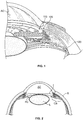
Figure 1 is a cross-sectional, perspective view of a portion of the eye showing the anterior and posterior chambers of the eye. -
Figure 2 is a cross-sectional view of a human eye. -
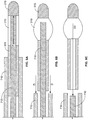
Figure 3A shows an embodiment of an implant at least partially formed of a braided structure. -
Figure 3B shows the implant ofFigure 3A in an expanded state. -
Figure 4 shows an exemplary embodiment of a section of the braided structure of the implant ofFigure 3A . -
Figure 5A shows another embodiment of an implant at least partially formed of a shape-changing material. -
Figure 5B shows the implant ofFigure 5A in an expanded state. -
Figures 6A-6C show an exemplary mechanism for delivering the implant ofFigure 3A . -
Figures 7A-7C show an exemplary mechanism for delivering the implant ofFigure 5A . -
Figures 8A-8C show exemplary methods of manufacturing a shape-changing portion of an implant. -
Figure 9 shows an exemplary delivery system that can be used to deliver an implant into the eye. -
Figure 10 shows a cross-sectional view of the eye and a viewing lens. -
Figure 11 shows the delivery system positioned for penetration into the eye. -
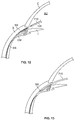
Figure 12 shows an enlarged view of the anterior region of the eye with a portion of the delivery system positioned in the anterior chamber. -
Figure 13 shows the distal tip of a delivery system positioned within the suprachoroidal space. -
Figure 1 is a cross-sectional, perspective view of a portion of the eye showing the anterior and posterior chambers of the eye. A schematic representation of animplant 105 is positioned inside the eye such that aproximal end 110 is located in the anterior chamber AC and adistal end 120 is located in or near the suprachoroidal space (sometimes referred to as the perichoroidal space). The suprachoroidal space can include the region between the sclera and the choroid. The suprachoroidal space can also include the region between the sclera and the ciliary body. In this regard, the region of the suprachoroidal space between the sclera and the ciliary body may sometimes be referred to as the supraciliary space. The implant described herein is not necessarily positioned between the choroid and the sclera. The implant may be positioned at least partially between the ciliary body and the sclera or it may be at least partially positioned between the sclera and the choroid. The implant may also be at least partially positioned in the suprachoroidal space. In any event, the implant provides a fluid pathway between the anterior chamber and the suprachoroidal space. - In an embodiment, the
implant 105 is an elongate element having one or more internal lumens through which aqueous humor can flow from the anterior chamber AC into the suprachoroidal space such as in the region between the sclera and the choroid. At least a portion of the implant is formed of a structure that is adapted to change from a first shape to a second shape. The change in shape can occur prior to, during, or after the implant is implanted in the eye, as described in more detail below. Theimplant 105 can have a substantially uniform diameter along its entire length, although the shape of theimplant 105 can vary along its length (either before or after insertion of the implant), as described below. Moreover, theimplant 105 can have various cross-sectional shapes (such as a, circular, oval or rectangular shape) and can vary in cross-sectional shape moving along its length. The cross-sectional shape can be selected to facilitate easy insertion into the eye. In one embodiment the implant is manufactured at least partially of a shape-changing material. At least a portion of the implant is formed of a braided structure that is adapted to change from a first shape to a second shape. - It should be appreciated the several shape change configurations are considered herein. It should also be appreciated that features described with respect to one embodiment can be used with other embodiments described herein.
-
Figure 2 is a cross-sectional view of a human eye. The eye is generally spherical and is covered on the outside by the sclera S. The retina lines the inside posterior half of the eye. The retina registers the light and sends signals to the brain via the optic nerve. The bulk of the eye is filled and supported by the vitreous body, a clear, jelly-like substance. - The elastic lens L is located near the front of the eye. The lens L provides adjustment of focus and is suspended within a capsular bag from the ciliary body CB, which contains the muscles that change the focal length of the lens. A volume in front of the lens L is divided into two by the iris I, which controls the aperture of the lens and the amount of light striking the retina. The pupil is a hole in the center of the iris I through which light passes. The volume between the iris I and the lens L is the posterior chamber PC. The volume between the iris I and the cornea is the anterior chamber AC. Both chambers are filled with a clear liquid known as aqueous humor.
- The ciliary body CB continuously forms aqueous humor in the posterior chamber PC by secretion from the blood vessels. The aqueous humor flows around the lens L and iris I into the anterior chamber and exits the eye through the trabecular meshwork, a sieve-like structure situated at the corner of the iris I and the wall of the eye (the corner is known as the iridocorneal angle). Some of the aqueous humor filters through the trabecular meshwork into Schlemm's canal, a small channel that drains into the ocular veins. A smaller portion rejoins the venous circulation after passing through the ciliary body and eventually through the sclera (the uveoscleral route).
- Glaucoma is a disease wherein the aqueous humor builds up within the eye. In a healthy eye, the ciliary processes secrete aqueous humor, which then passes through the angle between the cornea and the iris. Glaucoma appears to be the result of clogging in the trabecular meshwork. The clogging can be caused by the exfoliation of cells or other debris. When the aqueous humor does not drain properly from the clogged meshwork, it builds up and causes increased pressure in the eye, particularly on the blood vessels that lead to the optic nerve. The high pressure on the blood vessels can result in death of retinal ganglion cells and eventual blindness.
- Closed angle (acute) glaucoma can occur in people who were born with a narrow angle between the iris and the cornea (the anterior chamber angle). This is more common in people who are farsighted (they see objects in the distance better than those which are close up). The iris can slip forward and suddenly close off the exit of aqueous humor, and a sudden increase in pressure within the eye follows.
- Open angle (chronic) glaucoma is by far the most common type of glaucoma. In open angle glaucoma, the iris does not block the drainage angle as it does in acute glaucoma. Instead, the fluid outlet channels within the wall of the eye gradually narrow with time. The disease usually affects both eyes, and over a period of years the consistently elevated pressure slowly damages the optic nerve.
-
Figure 3A shows a first embodiment of theimplant 105 in an unexpanded state. As mentioned, theimplant 105 is an elongate member having a proximal end, a distal end, and a structure that permits fluid (such as aqueous humour) to flow along the length of the implant such as through the implant or around the implant. In the embodiment ofFigure 3A , the implant includes at least one internal lumen having at least one opening for ingress of fluid (such as aqueous humor from the anterior chamber) and at least one opening for egress of fluid. Theimplant 105 can include various arrangements of openings that communicate with the lumen(s). - The internal lumen serves as a passageway for the flow of aqueous humour through the
implant 105 directly from the anterior chamber to the suprachoroidal space. In addition, the internal lumen can be used to mount theimplant 105 onto a delivery system, as described below. The internal lumen can also be used as a pathway for flowing irrigation fluid into the eye generally for flushing or to maintain pressure in the anterior chamber, or using the fluid to hydraulically create a dissection plane into or within the suprachoroidal space. In the embodiment ofFigure 3A , theimplant 105 has a substantially uniform diameter along its entire length, although the diameter of the implant can vary along its length (either before or after expansion of the implant), as described below. Moreover, the implant can have various cross-sectional shapes (such as a circular, oval or rectangular shape) and can vary in cross-sectional shape moving along its length. The cross-sectional shape can be selected to facilitate easy insertion into the eye. -
Figure 3A shows embodiment of theimplant 105 comprised of a tubular or partially tubular structure. Theimplant 105 is at least partially manufactured of a mesh or braided structure formed of two or more interwoven strands, fibers, or threads of material. The interwoven strands can be arranged in a pattern that forms diamond-shaped holes or openings therebetween or openings of other shapes. The braided structure can be positioned over or otherwise combined with a solid tube wherein the solid tube has an internal lumen through which fluid can travel. Thus, the braided structure and the solid tube collectively form a braid-reinforced structure. - With reference to
Figure 3A , theimplant 105 has aproximal section 305, acentral section 310, and adistal section 315. In an embodiment, theproximal section 305 is formed of a solid tube (with internal lumen) that is overlayed with a braided structure such that theproximal section 305 is a braid-reinforced section. In an embodiment, thecentral section 310 is formed entirely of a braided structure. In another embodiment, thecentral section 310 is partially coated with a material. Thedistal section 315 comprises a distal tip that is not overlayed with a braided structure or that is partially overlayed with a braided structure. Thedistal section 315 can have an internal lumen or it can be entirely solid with no internal lumen. Thecentral section 310 is "open" in that the openings between the strands of the braided structure are uncovered. Thus, fluid can flow through the openings in an unimpeded manner. On the other hand, theproximal section 305 anddistal section 315 are "closed" in that the solid structure blocks the openings between the strands of the braided structure, where present. The openings in the braided structure can be filled with a material or mixture of materials, such as a sponge material, to prevent unwanted tissue ingrowth into the openings when the device is implanted in the eye. The sponge material can also be filled with a drug or other material that leaks into the eye upon implantation. - The braided structure of the implant is configured to change shape, such as to expand outward, during or after implantation in the eye. The shape change can facilitate anchoring in the eye and prevent migration of the implant once it is positioned in the eye. In addition, the shape change causes the openings in the braided structure to widen, which permits increased flow through the implant and reduces the likelihood of the implant becoming clogged. During delivery of the
implant 105, the openings can be positioned so as to align with predetermined anatomical structures of the eye. For example, one or more openings can align with the suprachoroidal space to permit the flow of aqueous humour into the suprachoroidal space, while another set of openings aligns with structures proximal to the suprachoroidal space, such as structures in the ciliary body or the anterior chamber of the eye. - The change in shape can be an outward expansion or can be any other change in shape, such as to change from a straightened to a non-straightened (e.g., curved or wavy) shape. The shape change can occur in a variety of manners. For example, the braided structure can be spring-loaded or biased such that the strands of the braid move relative to one another or deform so that the braid springs open to cause the openings between the strands to enlarge in size. The strands of the braid can be formed of a material, such as a spring metal or superelastic metal, that is heat or cold treated or pressure set to a desired spring-open configuration. The strands can also be formed of a polymer or can be formed of a composite (fiber-reinforced strands).
- During delivery of the implant into the eye, the implant is constrained in an alternate shape and then is released to permit the implant to revert to the heat-set shape. Alternately, the spring-open action can be provided by coating the openings, the fibers, and/or the fiber cross-over locations in the braided structure with an elastomer. In another embodiment, the braided structure is at least partially formed of a shape-change material that changes shape in response to predetermined conditions, such as a change in temperature.
- In another embodiment, which does not form part of the present invention, the
proximal section 305 anddistal section 315 both are formed of braided structures. Thecentral section 310 is formed of a solid structure that is overlayed or partially overlayed with a braided structure. Any of the sections can have an internal lumen that extends through the section. As in the previous embodiment, the braidedsections sections 305 and/or 315 can transition to an expanded shape. It should be appreciated that the implant can have various combinations and geometric arrangements of solid, braid reinforced structures and braided structures. - In any of the embodiments, the ends of the braided structure can be gathered and held in place by an adjacent solid structure, such as a bullet nose at the distal tip of the implant or a tube at the proximal tip.
-
Figure 3B shows the implant ofFigure 3A in an expanded state. The "open"central section 310 has enlarged to an expanded state. In an embodiment, the shape of theproximal section 305 anddistal section 315 do not undergo expansion and are unchanged. Alternately, the proximal and distal sections have undergone some expansion or other shape change (e.g., contraction or expansion) but the amount of expansion is less than the expansion of the braidedcentral section 310. The presence of the solid portions in the proximal and distal sections keeps the braided structure if present, in those sections from expanding outward. When implanted in the eye, fluid can pass into theimplant 105 via the internal lumen of theproximal section 305. Fluid travels into the internal lumen of the central section 310 (toward the distal section 315) where the fluid drains though the openings in the braided structure of the central section. - The
implant 105 can have any of a variety braided structures and non-braided structures that are connected and arranged in various manners.Figure 4 shows an exemplary embodiment of a section of braided structure. It should be appreciated that the structure ofFigure 4 is an example and that the braided structure can have other arrangements. In the exemplary embodiment, the braided structure is a triaxial braid structure having a plurality ofaxial members 505 that extend generally parallel to the longitudinal axis of the implant. The braided structure forms a three dimensional tube shape. A plurality ofcross-members axial members 505 at a braiding angle A relative to the axes of theaxial members 505. In cross-section, theaxial members 505 andcross-members axial members 505 are elastic (e.g., formed of an elastomer) while the cross-members 510,511 are formed of a high-strength material. The braids can be arranged in a variety of patterns including, for example, a one-over pattern, diamond pattern, non-diamond pattern. The axial members or cross-members can be flat banded fibers. That is, the members can have flat outer surfaces and can be rectangular in cross-section. -
Figure 5A shows another embodiment of a shape change implant. As with the previously described embodiment, theimplant 105 is an elongate member that has aproximal region 305, adistal region 315, and a generally tubular or partially tubular structure that permits fluid (such as aqueous humor) to flow along the length of the implant such as through or around the implant. Theimplant 105 includes at least one internal lumen having at least one opening for ingress of fluid (such as aqueous humor from the anterior chamber) and at least one opening for egress of fluid. Theimplant 105 can include various arrangements ofopenings 125 that communicate with the lumen(s). Theopenings 125 in theimplant 105 can be filled with a material or mixture of materials, such as a sponge material, to prevent unwanted tissue ingrowth into theopenings 125 when the device is implanted in the eye. The sponge material can also be filled with a drug or other material that leaks into the eye upon implantation. - As with the previous embodiment, the
openings 125 of the implant can be positioned so as to align with predetermined anatomical structures of the eye. For example, one ormore openings 125 can align with the suprachoroidal space to permit the flow of aqueous humor into the suprachoroidal space, while another set ofopenings 125 can be positioned within structures proximal to the suprachoroidal space, such as structures in the ciliary body or the anterior chamber of the eye. - In the embodiment shown in
Figure 5A , theimplant 105 is at least partially manufactured of a shape changing material. In an embodiment, thedistal region 315 includes a shape changing portion. The shape changing portion of theimplant 105 is configured to change shape upon insertion in the eye, for example theimplant 105 can bow outward. The shape change can facilitate anchoring and retention in the eye and prevent migration of theimplant 105 once it is in position. In addition, the shape change can cause theopenings 125 to widen, which permits increased flow through theimplant 105 and reduces the likelihood of theimplant 105 becoming clogged. - During delivery of the
implant 105 into the eye, the implant is constrained in a first shape conducive to insertion in the eye (see, for example,FIG. 5A ). The first shape can be a relatively straight configuration. Theimplant 105 is then released to permit the implant to revert to a second shape conducive to retention of the implant in the eye (see, for example,FIG. 5B ). The first shape can be a stressed or constrained shape whereas the second shape can be an unstressed or relaxed shape of the implant. The change from a first to a second shape can be an outward bowing as shown in the figures. The change in shape can be any other change in shape, such as to change from a straightened to a non-straightened (e.g., curved or wavy) shape or from a narrow to an expanded shape. - The shape change can occur in a variety of manners. For example, the implant can be manufactured of a thermoplastic elastomer (TPE) that is capable of being reversibly deformed as discussed in more detail below. The
implant 105 can be heat-set such that it is has a tendency to return from the first, constrained shape desired during delivery to the second, relaxed shape desired for retention and fluid passage. Theimplant 105 maintains the first shape when the implant is constrained in some manner such as by a guidewire or other delivery mechanism or device having a lower flexibility or elasticity than the shape changing portion of theimplant 105. When theimplant 105 is at or near the desired location in the eye, the constraint(s) can be removed or the implant released, such as by removal of the guidewire or other structure, so that the implant transitions or changes toward the second, retention shape such as shown inFigures 5B . - The implants described herein can include additional features to improve their effectiveness in draining fluid from the anterior chamber to the suprachoroidal space. For example, the implants described herein can be equipped with a
collar 325 disposed on or near the proximal end of the implant. As shown inFigures 3A and5A , thecollar 325 is shown in phantom lines to indicate that thecollar 325 is optional. Thecollar 325 can be formed of the same material as the rest of theimplant 105 or a different material. Thecollar 325 can have various shapes including a funnel shape such that thecollar 325 provides a relatively wide opening that communicates with the internal lumen of theimplant 105. In an embodiment, thecollar 325 is formed of a braided structure and is funnel shaped such that thecollar 325 provides a relatively wide opening that communicates with the internal lumen of theproximal section 305. In another embodiment, thecollar 325 is formed of a braid-reinforced plastic material. In another embodiment, thecollar 325 is formed of plastic but is not braid-reinforced. - The implants described herein can also include additional structural features in addition to the shape change region that assist in anchoring or retaining the implant in the eye. For example, the implant can include one or more retaining or retention structures, such as flanges, protrusions, wings, tines, or prongs, that lodge into the surrounding eye anatomy to retain the implant in place and prevent the implant from moving further into the suprachoroidal space. The retention features can also provide regions for fibrous attachment between the implant and the surrounding eye anatomy.
- The additional retention structures can be deformable or stiff and can be made of various biocompatible materials such as described above. For example, the additional retention structures can be made from thin 0,0254 mm ( 0.001" ) thick polyimide, which is flexible, thin 0.0762 mm ( 0.003" ) silicone elastomer which is also flexible, or stainless steel or Nitinol. Alternatively, the additional retention structures could be rings of polyimide. It should be appreciated that other materials can be used to make the additional retention structures. The shape of additional retention structures can vary. Alternatively, the additional retaining features can be manufactured as separate parts and assembled onto the implant as described above. They can fit into grooves, holes or detents in the body of the implant to lock them together. If the additional retaining features are constructed from hairs or sutures, they can be threaded or tied onto the implant. Alternatively, the additional retaining features can be overmolded onto the implant via an injection molding process. In an embodiment, the entire implant and additional retention features can be injection molded in one step. In another embodiment, the additional retaining features can be formed into the implant with a post-processing step such as such as those described in more detail below.
- The implants described herein can have one or more features that aid in properly positioning the implant in the eye. For example, the implants can include one or more visual, tomographic, echogenic, or radiopaque markers along the length to assist the user in positioning the desired portion of the implant within the anterior chamber and the desired portion within the suprachoroidal space. In using the markers to properly place the implant, the implant is inserted in the suprachoroidal space, until the marker is aligned with a relevant anatomic structure, for example, visually identifying a marker on the anterior chamber portion of the implant that aligns with the trabecular meshwork, or scleral spur, such that an appropriate length of the implant remains in the anterior chamber. Under ultrasound, an echogenic marker can signal the placement of the device within the suprachoroidal space. Any marker can be placed anywhere on the device to provide sensory feedback to the user on real-time placement, confirmation of placement or during patient follow up. Further, the implants and delivery system can employ alignment marks, tabs, slots or other features that allow the user to know alignment of the implant with respect to the delivery device.
- As described above, the implants described herein are configured to change shape, such as to bow or expand outward, during or after implantation in the eye. The material of the
implant 105 can be reversibly deformed such that it can take on a narrow profile (e.g. such as shown inFigures 3A and5A ) that is suitable for insertion through a small opening and then return to the retention shape (e.g. such as shown inFigures 3B and5B ). The implant maintains the alternate, insertion shape when it is under a tension or constrained in some manner. When the implant is at or near the desired location in the eye, the constraint(s) can be removed or released so that the implant reverts or transitions back to a relaxed retention shape. -
Figure 6A shows one embodiment of a cross-sectional view of animplant 105 attached to a distal region of a delivery system. The entire delivery system is described in more detail below. The delivery system includes a constraining structure, such as asheath 710, that is sized and shaped to receive theproximal section 305 of the implant. Thesheath 710 removably attaches to and constrains theproximal section 305 such as via a press-fit or any other type of mechanical attachment. - The delivery system also includes an
elongate delivery wire 715 that is sized and shaped to be inserted longitudinally through the internal lumen of theimplant 105. Thedelivery wire 715 is more rigid than theimplant 105 such that it constrains theimplant 105 in the straighter, insertion configuration. Although thedelivery wire 715 is more rigid than the implant, it still remains flexible and compliant enough to allow for blunt dissection such as between the tissue layers of the sclera and choroid and able to follow the natural curve of the inner scleral wall. It should be appreciated that other structures can be used to constrain theimplant 105. -
Figure 6A shows thesheath 710 attached to theproximal section 305 of the implant such that thesheath 710 fits over theproximal section 305 to constrain it to the size of the inner diameter of thesheath 710. With theproximal section 305 constrained, thedelivery wire 715 applies a distally-directed force F against thedistal section 315 such that the implant is in tension. The force F against thedistal section 315 combined with the implant's attachment to theproximal section 305 cause the braidedcentral section 310 to be in a stretched state of reduced diameter and increased length relative to a non-stretched state. In other words, the delivery system constrains and maintains theimplant 105 in the first shape shown inFigure 3A . -
Figure 6B shows the delivery system after thesheath 710 has been retracted distally (represented by the arrows D) relative to the implant and thereby detached from theproximal section 305 of theimplant 105. While thesheath 710 was attached to the implant, thesheath 710 and thedelivery wire 715 collectively maintained the implant in a state of tension. With thesheath 710 no longer constraining theproximal section 305 in a state of tension, theimplant 105 is now free to move toward its expanded shape. The braidedcentral section 310 moves toward its expanded shape such that thecentral section 310 changes to a bulbous shape. As this occurs, thedistal section 315 moves away from the distal tip of the delivery wire 715 (or vice-versa), as shown inFigure 6B . - In a next step, shown in
Figure 6C , thedelivery wire 715 is retracted distally (as represented by the arrow D2) relative to theimplant 105 such that thedelivery wire 715 and thesheath 710 are both entirely disengaged from theimplant 105. Theimplant 105 is now entirely free to transition toward its second retention shape. As discussed above, the second shape may be of smaller length but greater diameter than the first shape. -
Figure 7A shows a schematic, cross-sectional view of another embodiment of animplant 105 attached to a distal region of a delivery system inserted from the anterior chamber AC into the suprachoroidal space SC. Like the previous embodiment, the delivery system can include a constraining structure such as asheath 710 that is sized and shaped to receive a portion of theproximal section 305 of the implant. For example, thesheath 710 can removably attach to theproximal section 305 such as via a press-fit or any other type of mechanical attachment. In this regard, thesheath 710 may have an internal lumen into which the implant fits such that the implant is removably constrained in thesheath 710. Other means of removably attaching thesheath 710 to the implant can be used. - The delivery system also includes an
elongate delivery wire 715 that is sized and shaped to be inserted longitudinally through the internal lumen of theimplant 105. Thedelivery wire 715 is more rigid than theimplant 105 such that it constrains theimplant 105 in the straighter, insertion configuration. Although thedelivery wire 715 is more rigid than the implant, it still remains flexible and compliant enough to allow for blunt dissection for example between the tissue layers of the sclera and choroid and able to follow the natural curve of the inner scleral wall. It should be appreciated that other structures can be used to constrain theimplant 105. -
Figure 7B shows the delivery system after thedelivery wire 715 has been retracted proximally (represented by the arrow P) relative to theimplant 105. With thedelivery wire 715 no longer constraining thedistal region 315 of the implant in a state of tension in the generally straight insertion configuration, thedistal region 315 of theimplant 105 is now free to move toward the retention shape. In the case ofFIGS. 7B and 7C , the retention shape is a wavy or bowed shape. In any of the embodiments described herein, the shape of the implant at body temperature does not deform beyond the yield during implantation. - In an embodiment, the
implant 105 has a longitudinal stiffness or column strength sufficient to permit theimplant 105 to be inserted into the suprachoroidal space such that the distal tip of theimplant 105 tunnels through certain eye tissue (such as the ciliary body) and between certain eye tissues (such as between the sclera and the choroid or between the sclera and the ciliary body) without structural collapse or structural degradation of theimplant 105. In addition, the surface of the inner lumen is sufficiently smooth relative to the delivery device (described in detail below) to permit theimplant 105 to slide off of the delivery device during the delivery process. In an embodiment, the column strength is sufficient to permit the implant to tunnel through certain eye tissues into the suprachoroidal space without any structural support from an additional structure such as a delivery device. - The dimensions of the implants described herein can vary. In an exemplary embodiment, the implant has a length in the range of 2,54 mm to 19,05 mm ( 0.1" to 0.75") and an inner diameter for a flow path in the range of 80,0508 mm to 0,381 mm ( 0.002" to 0.015"). In an embodiment, the inner diameter is,3048 mm (0.012"), 0,254 mm (0.010"), 0,2032 mm (0.008"). In the event that multiple implants are used, and for example each implant is 2,54 mm (0.1"), the fully implanted device can create a length of 5,08 mm to 25,4 mm ( 0.2" to 1.0"), although the length can be outside this range. An embodiment of the implant is 6,35 mm ( 0.250" ) long, 0,3048 mm ( 0.012" ) in inner diameter, and 0,381 mm ( 0.015" ) in outer diameter. One embodiment of the implant is 7,62 mm ( 0.300") long.
- The implants described herein including their shape changing portion(s) can be made of various biocompatible materials. In an embodiment, the implants can be manufactured of synthetic polymeric materials that show reversible extension and can be deformed repeatedly such that they return to their "original" heat-set shape when the stress is released. The reversible deformation of the implant, even at higher body temperatures, is a desirable characteristic.
- The implant or portion(s) thereof can be made of various materials, including, for example, thermoplastic elastomers, polyimide, Nitinol, platinum, stainless steel, molybdenum, or any other suitable polymer, metal, metal alloy, or ceramic biocompatible material or combinations thereof. The material of manufacture is desirably selected to have material properties suited for the particular function of the implant or portion thereof.
- Other materials of manufacture or materials with which the implant can be coated or manufactured entirely include silicone, thermoplastic elastomers (HYTREL, KRATON, PEBAX), certain polyolefin or polyolefin blends, elastomeric alloys, polyurethanes, thermoplastic copolyester, polyether block amides, polyamides (such as Nylon), block copolymer polyurethanes (such as LYCRA). Some other exemplary materials include fluoropolymer (such as FEP and PVDF), polyester, ePTFE (also known as GORETEX), FEP laminated into nodes of ePTFE, acrylic, low glass transition temperature acrylics, silver coatings (such as via a CVD process), gold, polypropylene, poly(methyl methacrylate) (PMMA), PolyEthylene Terephthalate (PET), Polyethylene (PE), PLLA, parylene, PEEK, polysulfone, polyamideimides (PAI) and liquid crystal polymers. It should also be appreciated that stiffer polymers can be made to be more compliant by incorporating air or void volumes into their bulk, for example, PTFE and expanded PTFE. In order to maintain a low profile, well-known sputtering techniques can be employed to coat the implant. Such a low profile coating would accomplish a possible goal of preventing migration while still allowing easy removal if desired.
- The implant can have braids or wires reinforced with polymer, Nitinol, or stainless steel braid or coiling or can be a co-extruded or laminated tube with one or more materials that provide acceptable flexibility and hoop strength for adequate lumen support and drainage through the lumen.
- The implant can also be manufactured of, coated or layered with a material that expands outward once the implant has been placed in the eye. The expanded material fills any voids that are positioned around the implant. Such materials include, for example, hydrogels, foams, lyophilized collagen, or any material that gels, swells, or otherwise expands upon contact with body fluids.
- Any of the embodiments of the implants described herein can be coated on the inner or outer surface with one or more drugs or other materials, wherein the drug or material maintains the patency of the lumen or encourages in-growth of tissue to assist with retention of the implant within the eye or to prevent leakage around the implant. The drug can also be used for disease treatment. The implant can also be coated on its inner or outer surface with a therapeutic agent, such as a steroid, an antibiotic, an anti-inflammatory agent, an anti-coagulant, an anti-glaucomatous agent, an anti-proliferative, or any combination thereof. The drug or therapeutic agent can be applied in a number of ways as is known in the art. Also the drug can be embedded in another polymer (nonabsorbable or bioabsorbable) that is coated on the implant.
- The shape change portion of the implant can be formed by one or more post-processing steps. Thermoplastic materials, including thermoplastic elastomers (TPEs), are characterized by labile cross-links that are reversible and can be broken when melted. This property of TPEs makes them easy to use from a manufacturing standpoint. The shape changing portion(s) of a thermoplastic implant can be processed by engineering the cross-links such as through heat, flaring, thermo-molding, pressure, chemicals or radiation such as electron beam exposure, gamma-radiation or UV light. Thermosets and cross-linked sets can also be used.
-
Figures 8A-8C show various post-processing steps used to create shape changing portions in an implant.Figure 8A shows an embodiment in which the shape changing portion of theimplant 105 is manufactured by a heating-molding-cooling series of steps to create an implant of a desired retention shape. Theimplant 105 can be made of a thermally-stimulated, shape-memory polymer, for example thermoplastic PVDF. Polymer pellets are extruded through a mold to form an elongate, hollow tube. At least a portion of the tubular implant is exposed again to heat, such as a heated mandrel M that heats a portion of theimplant 105, to a temperature above the Tg (glass transition temperature) of the material such that it goes from a rigid, glassy modulus to the rubbery modulus. Once in the rubbery modulus, theimplant 105 can be deformed as desired, for example a funnel-shapedcollar 325 formed in the proximal portion or an s-shaped curve in thedistal portion 315. Theimplant 105 can then be cooled below the Tg. Upon cooling, the implant will retain this curved shape yet due to the flexible nature of the polymer, stress can be applied to the implant (e.g. inserting a delivery wire through the internal lumen) to temporarily change the shape of the implant to a different shape. As described above, upon removal of the constraint (e.g. removal of the delivery wire), theimplant 105 will reversibly deform back into the "retention" shape. - The ability to melt and process the material of the implant is useful from a manufacturing stand-point, but can limit a material's use in elevated temperatures (i.e. inside the human body). Therefore, post-processing steps can also be used to overcome this limitation so that the implant can be used at and even above the melting point of the material without changing the properties of the material or the dimensions of the implant. For example, cross-linking thin-wall extrusion implants imparts stiffness to the implant while retaining the elastomeric properties of the material of which it is made. The end result is high durability within a wide range of temperatures and/or pressures.
- Other cross-linking techniques include exposing the extruded implant to radiation (UV, gamma, or electron beam) or through a chemical process using, for example, peroxide or silane. The reactions produced by cross-linking depend on the particular material, the presence of modifying agents, and variables in processing, such as the level of irradiation.
Figures 8B and 8C show schematics of exemplary post-processing steps in which cross-linking is induced by exposure of at least a portion of the implant to radiation, such as UV, gamma or electron beam radiation to generate thermal memory in an implant. A portion of the implant that is not cross-linked can be covered with an appropriate shield S. - With respect to the braided implant embodiment, the solid proximal and distal sections of the implant can be cast, coated (e.g., dip-coated, vapor-coated, or powder-coated), bonded, trapped (i.e., sandwiched) or otherwise attached into or onto the braided structure. In an embodiment, at least a portion of the implant is reaction cast around reinforcing wire. The strands of the braided portions of the implant can be joined to form a bulb or funnel shape, such as by welding or cold working the strands or by bonding the strands in epoxy or other matrix glues. In addition, the strands can be knotted, encapsulated with a heat shrink, insert injection molded, diffusion bonded, solvent welded, etc. The fiber cross-overs can also be crimp-set during the braiding process.
- There are now described devices and methods for delivering and deploying implant described herein into the eye. A delivery system is used to deliver the implant into the eye such that the implant provides fluid communication between the anterior chamber and the suprachoroidal space.
Figure 9 shows anexemplary delivery system 905 that can be used to deliver the implant into the eye. It should be appreciated that thedelivery system 905 is exemplary and that variations in the structure, shape and actuation of thedelivery system 905 are possible. - The
delivery system 905 includes ahandle component 910 that controls an implant placement mechanism, and adelivery component 915 that removably couples to the implant for delivery of the implant into the eye. Thedelivery component 915 includes an elongate delivery wire 715 (which was previously discussed above) that is sized and shaped to be inserted longitudinally through the implant. The diameter of thedelivery wire 715 is at least 0,04318 mm (0.0017") or the diameter of thedelivery wire 715 is at least about 0,2286 mm (0.09"). Thedelivery wire 715 has a sharpened distal tip although it can also be blunt. Thedelivery wire 715 can have a cross-sectional shape that complements the cross-sectional shape of the internal lumen of the implant to facilitate mounting of the implant onto thedelivery wire 715. Thedelivery wire 715 can be straight or it can be can be curved along all or a portion of its length in order to facilitate proper placement through the cornea. Thedelivery wire 715 is generally more rigid than theimplant 105 such that it constrains theimplant 105 in the straighter, insertion configuration. Although thedelivery wire 715 is more rigid than the implant, it still remains flexible and compliant enough to allow for blunt dissection such as between the tissue layers of the sclera and choroid or the sclera and the ciliary body and able to follow the natural curve of the inner scleral wall. - The outer diameter of the delivery wire can be selected and optimized based on the material and flexibility of the material used for the delivery wire. A delivery wire made of nitinol, for example, can have an outer diameter of about 0,2286 mm (0.009"). Nitinol is a superelastic metal that is quite bendable yet is stiff enough to be pushed through the iris root and the ciliary body to reach to and hug the curve of the inner scleral wall during blunt dissection along the boundary between the sclera and the tissues adjacent to the inner scleral wall. When combined with other features of the delivery wire, for example a blunt tip, a nitinol delivery wire having an outer diameter of about 0,2286 mm ( 0.009 inches can be used to gently dissect the tissue layers while avoiding tunneling or piercing one or both the inner scleral wall and choroid. Stainless steel spring wire is another material that could be used for the delivery wire. Stainless steel wire is generally slightly stiffer than nitinol. Thus, the outer diameter of a delivery wire made of stainless steel wire may need to be somewhat smaller than the outer diameter for a delivery wire made of nitinol in order to achieve the same performance during blunt dissection. In an embodiment, the delivery wire has an outer diameter of about 0,04318 mm ( 0.0017 inches). It should be appreciated that for a given material's flexibility, the optimum outer diameter of the delivery wire can be determined and extrapolated for a delivery wire of a different material having a different degree of flexibility. Other materials considered for the delivery wire include compliant flexible wires made from a polymer or a polymer composite wire reinforced with high-strength fibers.
- A variety of parameters including the shape, material, material properties, diameter, flexibility, compliance, pre-curvature and tip shape of the
delivery wire 715 can impact the performance of thedelivery wire 715 during gentle, blunt tissue dissection. It may be important that thedelivery wire 715 be able to penetrate certain tissues while avoid penetration of other tissues. For example, in an embodiment, it is desirable that thedelivery wire 715 be capable of penetrating the iris root or the ciliary body. Thesame delivery wire 715 would beneficially be incapable of penetrating the scleral spur or inner wall of the sclera such that it can gently dissect between the tissue boundaries adjacent to the inner wall of the sclera. It should also be appreciated that the column strength of the implant can be sufficient to permit the implant to tunnel through certain eye tissues into the suprachoroidal space without any structural support from an additional structure such as a delivery wire. - The
delivery component 915 also includes asheath 710 positioned axially over thedelivery wire 715. Thesheath 710 can be coupled to the implant during delivery to maintain or assist in maintaining the implant in an insertion configuration, as discussed above. With reference still toFigure 9 , thehandle component 910 of thedelivery system 905 can be actuated to control delivery of the implant. In this regard, thehandle component 910 includes anactuator 920 that can be actuated to cause relative, sliding movement between thedelivery wire 715 and thesheath 710. For example, theactuator 920 can be manipulated to cause thedelivery wire 715 to withdraw proximally relative to thesheath 710. The proximal direction is represented by the arrow P inFigure 7B . - As mentioned the
delivery wire 715 is sized to fit through the lumen in theimplant 105 such that theimplant 105 can be mounted on thedelivery wire 715. In an embodiment, thedelivery wire 715 can be coated such that a press-fit between theimplant 105 and thedelivery wire 715 is possible. For example, thedelivery wire 715 or a portion of thedelivery wire 715 can be coated with a polymer or other compliant material in order to retain the implant on thedelivery wire 715 during implantation and prevent inadvertent release of the implant within the eye. - An exemplary method of delivering and implanting the implant into the eye is now described. In general, the implant is implanted using a delivery system by entering the eye through a corneal incision and penetrating the iris root or a region of the ciliary body or the iris root part of the ciliary body near its tissue border with the scleral spur to create a low-profile, minimally-invasive blunt dissection in the tissue plane, for example between the sclera and the ciliary body or between the sclera and the choroid. The implant is then positioned in the eye so that it provides fluid communication between the anterior chamber and the suprachoroidal space.
-
Figure 10 shows a cross-sectional view of the eye. A viewing lens 1405 (such as a gonioscopy lens represented schematically inFigure 10 ) is positioned adjacent the cornea. Theviewing lens 1405 enables viewing of internal regions of the eye, such as the scleral spur and scleral junction, from a location in front of the eye. An operator can use theviewing lens 1405 during delivery of the implant into the eye. Theviewing lens 1405 can have a shape or cutout that permits the surgeon to use theviewing lens 1405 in a manner that does not cover or impede access to the corneal incision. Further, theviewing lens 1405 can act as a guide through which adelivery system 905 can be placed to predetermine the path of the device as it is inserted through the cornea. Theviewing lens 1405 can optionally include one ormore guide channels 1410 that are sized to receive thedelivery portion 915 of thedelivery system 905. It should be appreciated that the locations and orientations of theguide channels 1410 inFigure 10 are merely exemplary and that the actual locations and orientations can vary depending on the angle and location where theimplant 105 is to be delivered. It should also be appreciated that a viewing lens need not be used. - An endoscope can also be used during delivery to aid in visualization. For example, a twenty-one to twenty-five gauge endoscope can be coupled to the implant during delivery such as by mounting the endoscope along the side of the implant or by mounting the endoscope coaxially within the implant. Ultrasonic guidance can be used as well using high resolution bio-microscopy, OCT and the like. Alternatively, a small endoscope can be inserted though a second limbal incision in the eye to image the tissue during the procedure.
- In an initial step, one or
more implants 105 are mounted on thedelivery system 905 for delivery into the eye. Theimplant 105 can be mounted on thedelivery system 905 such as by inserting adelivery wire 715 through the flow pathway of the implant. The eye can be viewed through theviewing lens 1405 or other viewing means such as is described above, in order to ascertain the location where theimplant 105 is to be delivered. At least one goal is to deliver theimplant 105 in the eye so that it is positioned such that the internal lumen of the implant provides a fluid pathway between the anterior chamber and the suprachoroidal space. - With reference to
Figure 11 , thedelivery system 905 is positioned such that the distal tip of thedelivery wire 715 or theimplant 105 itself can penetrate through the cornea. In this regard, an incision is made through the eye, such as within the limbus of the cornea. In an embodiment, the incision is very close to the limbus, such as either at the level of the limbus or within 2 mm of the limbus in the clear cornea. Thedelivery wire 715 can be used to make the incision or a separate cutting device can be used. For example, a knife-tipped device or diamond knife can be used to initially enter the cornea. A second device with a spatula tip can then be advanced over the knife tip wherein the plane of the spatula is positioned to coincide with the dissection plane. Thus, the spatula-shaped tip can be inserted into the suprachoroidal space with minimal trauma to the eye tissue. As described above, the dynamics of thedelivery wire 715 such as material, material properties, dimensions, compliance, flexibility etc. contribute in part to the blunt dissection of the eye tissue and ensure that the implantation pathway follows the natural pathway between tissue layers, for example between tissue layers such as the sclera and choroid. - The corneal incision has a size that is sufficient to permit passage of the implant therethrough. In this regard, the incision can be sized to permit passage of only the implant without any additional devices, or be sized to permit passage of the implant in addition to additional devices, such as the delivery device or an imaging device. In an embodiment, the incision is about 1 mm in size. In another embodiment, the incision is no greater than about 2.85 mm in size. In another embodiment, the incision is no greater than about 2.85 mm and is greater than about 1.5 mm. It has been observed that an incision of up to 2.85 mm is a self-sealing incision. For clarity of illustration, the drawing is not to scale and the
viewing lens 1405 is not shown inFigure 11 , although the applier can be guided through one or more guide channels in the viewing lens. - The
delivery wire 715 can approach the iris root IR from the same side of the anterior chamber AC as the deployment location such that the applier (e.g. delivery wire) does not have to be advanced across the iris. Alternately, the applier can approach the insertion location from across the anterior chamber AC such that the applier is advanced across the iris and/or the anterior chamber toward the opposite iris root. Thedelivery wire 715 can approach the iris root IR along a variety of pathways. Thedelivery wire 715 does not necessarily cross over the eye and does not intersect the center axis of the eye. In other words, the corneal incision and the location where the implant is implanted at the iris root can be in the same quadrant (if the eye is viewed from the front and divided into four quadrants). Also, the pathway of the implant from the corneal incision to the iris root desirably does not pass through the centerline of the eye to avoid interfering with the pupil. -
Figure 12 shows an enlarged view of the anterior region of the eye. After insertion through the incision, the implant mounted on thedelivery wire 715 is advanced through the cornea into the anterior chamber along a pathway that enables the implant to be delivered to a position such that the implant provides a flow passageway from the anterior chamber into the suprachoroidal space. The applier travels along a pathway that is toward the scleral spur such that the applier passes near the scleral spur on the way to the suprachoroidal space. The scleral spur is an anatomic landmark on the wall of the angle of the eye. The scleral spur is above the level of the iris but below the level of the trabecular meshwork. In some eyes, the scleral spur can be masked by the lower band of the pigmented trabecular meshwork and be directly behind it. In a preferred embodiment, the applier does not pass through the scleral spur during delivery. Rather, the applier abuts the scleral spur and then moves downward to dissect the tissue boundary between the sclera and the ciliary body, the dissection entry point starting just below (posterior) the scleral spur. The applier can penetrate the iris root or a region of the ciliary body or the iris root part of the ciliary body near its tissue border with the scleral spur. The combination of delivery wire properties and the angle of approach allows the procedure to be performed "blind" as the instrument tip follows the inner curve of the scleral wall to dissect the tissue and create a mini cyclo-dialysis channel to connect the anterior chamber to the suprachoroidal space. The surgeon can rotate or reposition the handle of the delivery device in order to obtain a proper approach trajectory for the distal tip of the applier, as described in further detail below. Thedelivery wire 715 can be pre-shaped, steerable, articulating, or shapeable in a manner that facilitates the applier approaching the suprachoroidal space along a proper angle or pathway. - As mentioned, the scleral spur is not necessarily penetrated during delivery. If penetration of the scleral spur is desired, penetration through the scleral spur can be accomplished in various manners. In one embodiment, a sharpened distal tip of the applier or the implant punctures, penetrates, dissects, pierces or otherwise passes through the scleral spur toward the suprachoroidal space. The crossing of the scleral spur or any other tissue can be aided such as by applying energy to the scleral spur or the tissue via the distal tip of the
delivery wire 715. The means of applying energy can vary and can include mechanical energy, such as by creating a frictional force to generate heat at the scleral spur. Other types of energy can be used, such as RF laser, electrical, etc. -
Figure 13 shows the distal tip of thedelivery wire 715 positioned within the suprachoroidal space SS. For clarity of illustration,Figure 13 does not show theimplant 105 mounted on the applier, although theimplant 105 is mounted on the applier during delivery. As thedelivery wire 715 advances through tissue, the distal tip causes the sclera to peel away or otherwise separate from the ciliary body or the choroid. As mentioned above, a variety of parameters including the shape, material, material properties, diameter, flexibility, compliance, pre-curvature and tip shape of thedelivery wire 715 make it more inclined to follow an implantation pathway that mirrors the natural pathway between tissue layers, for example between tissue layers the sclera and choroid, and the curvature of the eye. Thedelivery wire 715 is continuously advanced into the eye, until the distal tip is located at or near the suprachoroidal space such that a first portion of theimplant 105 is positioned within the suprachoroidal space and a second portion is positioned within the anterior chamber. In one embodiment, at least 1 mm to 2 mm of the implant (along the length) remains in the anterior chamber. Theimplant 105 is then released from the delivery wire in the manner described above with reference toFigures 6A-6C orFigures 7A-7C . - A cyclodialysis procedure is performed using an alternate embodiment of the
delivery system 905. In this embodiment, thedelivery wire 715 is a needle with a sharpened distal tip such that the needle can puncture, dissect, or otherwise form a passageway into the suprachoroidal space from the anterior chamber. Either immediately before or after a cataract procedure (or during the procedure) on the eye, the distal tip of the needle is used to form a micro cyclodialysis dissection. This forms a vent between the anterior chamber and the suprachoroidal space that can serve to vent pressure from the anterior chamber into the suprachoroidal space. In an embodiment, the needle is heated to heat-set the eye tissue around it so that the micro-cyclodialysis has more of a tendency to remain open for a desired time period. The micro-cyclodialysis may remain open for a period of 3 hours to 24 hours. In an embodiment, the micro-cyclodialysis remains open for 8 hours or for an overnight period. A fast resorbing implant (i.e., resorbs within 8 hours) can be implanted into the passageway formed by the micro-cyclodialysis. The implant has a passageway that connects the anterior chamber and suprachoroidal space.
Claims (5)
- An ocular implant, comprising:an elongate member having a flow pathway, at least one inflow port communicating with the flow pathway, and an outflow port communicating with the flow pathway, wherein the elongate member includes a first portion formed of a braided structure and adapted to transition between a first shape when in tension and a second shape upon release of tension, and a second portion formed at least partially of a non-braided structure wherein the elongate member includes a third portion formed of a non-braided structure and wherein the first portion is positioned between the second and third portions;wherein the elongate member is adapted to be positioned in the eye such that the inflow port communicates with the anterior chamber and the outflow port communicates with the suprachoroidal space.
- An implant as in claim 1, wherein the first portion is adapted to transition from the first shape to the second shape while the second portion remains unchanged in shape,
- An implant as in claim 1, wherein the second portion is overlayed with a braided structure.
- An implant as in claim 1, wherein the first portion transitions to a state of reduced diameter under tension and transitions to a state of enlarged diameter upon removal of tension.
- An implant as in claim 1, wherein the flow pathway is an internal lumen that extends through at least one of the first and second portions.
Priority Applications (1)
| Application Number | Priority Date | Filing Date | Title |
|---|---|---|---|
| EP17183920.2A EP3298995A1 (en) | 2008-06-25 | 2009-06-25 | Ocular implant with shape change capabilities |
Applications Claiming Priority (3)
| Application Number | Priority Date | Filing Date | Title |
|---|---|---|---|
| US7570608P | 2008-06-25 | 2008-06-25 | |
| US7612108P | 2008-06-26 | 2008-06-26 | |
| PCT/US2009/048703 WO2009158524A2 (en) | 2008-06-25 | 2009-06-25 | Ocular implant with shape change capabilities |
Related Child Applications (1)
| Application Number | Title | Priority Date | Filing Date |
|---|---|---|---|
| EP17183920.2A Division EP3298995A1 (en) | 2008-06-25 | 2009-06-25 | Ocular implant with shape change capabilities |
Publications (2)
| Publication Number | Publication Date |
|---|---|
| EP2334268A2 EP2334268A2 (en) | 2011-06-22 |
| EP2334268B1 true EP2334268B1 (en) | 2017-08-02 |
Family
ID=41016765
Family Applications (2)
| Application Number | Title | Priority Date | Filing Date |
|---|---|---|---|
| EP17183920.2A Withdrawn EP3298995A1 (en) | 2008-06-25 | 2009-06-25 | Ocular implant with shape change capabilities |
| EP09771056.0A Active EP2334268B1 (en) | 2008-06-25 | 2009-06-25 | Ocular implant with shape change capabilities |
Family Applications Before (1)
| Application Number | Title | Priority Date | Filing Date |
|---|---|---|---|
| EP17183920.2A Withdrawn EP3298995A1 (en) | 2008-06-25 | 2009-06-25 | Ocular implant with shape change capabilities |
Country Status (4)
| Country | Link |
|---|---|
| US (2) | US8617139B2 (en) |
| EP (2) | EP3298995A1 (en) |
| ES (1) | ES2640867T3 (en) |
| WO (1) | WO2009158524A2 (en) |
Families Citing this family (88)
| Publication number | Priority date | Publication date | Assignee | Title |
|---|---|---|---|---|
| US7867186B2 (en) | 2002-04-08 | 2011-01-11 | Glaukos Corporation | Devices and methods for treatment of ocular disorders |
| US6638239B1 (en) | 2000-04-14 | 2003-10-28 | Glaukos Corporation | Apparatus and method for treating glaucoma |
| EP1418868B1 (en) | 2001-04-07 | 2008-03-26 | Glaukos Corporation | Glaucoma stent for glaucoma treatment |
| US7331984B2 (en) | 2001-08-28 | 2008-02-19 | Glaukos Corporation | Glaucoma stent for treating glaucoma and methods of use |
| US20040225250A1 (en) | 2003-05-05 | 2004-11-11 | Michael Yablonski | Internal shunt and method for treating glaucoma |
| US7291125B2 (en) | 2003-11-14 | 2007-11-06 | Transcend Medical, Inc. | Ocular pressure regulation |
| EP3632385A1 (en) | 2006-01-17 | 2020-04-08 | Novartis AG | Glaucoma treatment device |
| US8308701B2 (en) | 2010-11-15 | 2012-11-13 | Aquesys, Inc. | Methods for deploying intraocular shunts |
| US8758290B2 (en) | 2010-11-15 | 2014-06-24 | Aquesys, Inc. | Devices and methods for implanting a shunt in the suprachoroidal space |
| US8852256B2 (en) | 2010-11-15 | 2014-10-07 | Aquesys, Inc. | Methods for intraocular shunt placement |
| US8721702B2 (en) | 2010-11-15 | 2014-05-13 | Aquesys, Inc. | Intraocular shunt deployment devices |
| US10085884B2 (en) | 2006-06-30 | 2018-10-02 | Aquesys, Inc. | Intraocular devices |
| US8974511B2 (en) | 2010-11-15 | 2015-03-10 | Aquesys, Inc. | Methods for treating closed angle glaucoma |
| US8663303B2 (en) | 2010-11-15 | 2014-03-04 | Aquesys, Inc. | Methods for deploying an intraocular shunt from a deployment device and into an eye |
| US8852137B2 (en) | 2010-11-15 | 2014-10-07 | Aquesys, Inc. | Methods for implanting a soft gel shunt in the suprachoroidal space |
| US20120123316A1 (en) | 2010-11-15 | 2012-05-17 | Aquesys, Inc. | Intraocular shunts for placement in the intra-tenon's space |
| US8801766B2 (en) | 2010-11-15 | 2014-08-12 | Aquesys, Inc. | Devices for deploying intraocular shunts |
| US9095411B2 (en) | 2010-11-15 | 2015-08-04 | Aquesys, Inc. | Devices for deploying intraocular shunts |
| US8506515B2 (en) | 2006-11-10 | 2013-08-13 | Glaukos Corporation | Uveoscleral shunt and methods for implanting same |
| WO2009012406A1 (en) * | 2007-07-17 | 2009-01-22 | Transcend Medical, Inc. | Ocular implant with hydrogel expansion capabilities reference to priority document |
| US20090082862A1 (en) | 2007-09-24 | 2009-03-26 | Schieber Andrew T | Ocular Implant Architectures |
| US7740604B2 (en) | 2007-09-24 | 2010-06-22 | Ivantis, Inc. | Ocular implants for placement in schlemm's canal |
| US20170360609A9 (en) | 2007-09-24 | 2017-12-21 | Ivantis, Inc. | Methods and devices for increasing aqueous humor outflow |
| US8734377B2 (en) | 2007-09-24 | 2014-05-27 | Ivantis, Inc. | Ocular implants with asymmetric flexibility |
| US8808222B2 (en) | 2007-11-20 | 2014-08-19 | Ivantis, Inc. | Methods and apparatus for delivering ocular implants into the eye |
| WO2009096851A1 (en) * | 2008-01-28 | 2009-08-06 | Milux Holding Sa | A drainage device comprising a filter cleaning device |
| AU2009221859B2 (en) | 2008-03-05 | 2013-04-18 | Alcon Inc. | Methods and apparatus for treating glaucoma |
| EP3298995A1 (en) | 2008-06-25 | 2018-03-28 | Novartis AG | Ocular implant with shape change capabilities |
| AU2009322146B2 (en) | 2008-12-05 | 2015-05-28 | Alcon Inc. | Methods and apparatus for delivering ocular implants into the eye |
| JP5524983B2 (en) | 2009-01-28 | 2014-06-18 | トランセンド・メディカル・インコーポレイテッド | Implant system |
| AU2010266013B2 (en) * | 2009-06-25 | 2015-03-26 | Alcon Inc. | Fiber matrix for maintaining space in soft tissues |
| EP2451375B1 (en) | 2009-07-09 | 2018-10-03 | Ivantis, Inc. | Single operator device for delivering an ocular implant |
| CN102481404B (en) | 2009-07-09 | 2014-03-05 | 伊万提斯公司 | Ocular implants |
| US8535333B2 (en) | 2009-07-29 | 2013-09-17 | Transcend Medical, Inc. | Ocular implant applier and methods of use |
| CN102647960A (en) * | 2009-10-23 | 2012-08-22 | 伊万提斯公司 | Ocular implant system and method |
| US8529492B2 (en) | 2009-12-23 | 2013-09-10 | Trascend Medical, Inc. | Drug delivery devices and methods |
| US9510973B2 (en) * | 2010-06-23 | 2016-12-06 | Ivantis, Inc. | Ocular implants deployed in schlemm's canal of the eye |
| DE102010035294A1 (en) * | 2010-08-25 | 2011-12-22 | Implandata Ophthalmic Products Gmbh | Sclera sensor |
| US20130267887A1 (en) * | 2010-09-21 | 2013-10-10 | The Regents Of The University Of Colorado | Aqueous humor micro-bypass shunts |
| US20130226292A1 (en) * | 2010-10-12 | 2013-08-29 | Jean-Marie Parel | Islet storing intraocular implant, method of using the same and kit including the same |
| US10842671B2 (en) | 2010-11-15 | 2020-11-24 | Aquesys, Inc. | Intraocular shunt placement in the suprachoroidal space |
| US9033963B2 (en) * | 2011-04-10 | 2015-05-19 | Fs-Eye, Llc | Systems and methods to deliver photodisruptive laser pulses into tissue layers of the anterior angle of the eye |
| US8657776B2 (en) | 2011-06-14 | 2014-02-25 | Ivantis, Inc. | Ocular implants for delivery into the eye |
| EP3659495B1 (en) * | 2011-09-13 | 2022-12-14 | Dose Medical Corporation | Intraocular physiological sensor |
| US9808373B2 (en) | 2013-06-28 | 2017-11-07 | Aquesys, Inc. | Intraocular shunt implantation |
| US10080682B2 (en) | 2011-12-08 | 2018-09-25 | Aquesys, Inc. | Intrascleral shunt placement |
| US8765210B2 (en) | 2011-12-08 | 2014-07-01 | Aquesys, Inc. | Systems and methods for making gelatin shunts |
| US9610195B2 (en) | 2013-02-27 | 2017-04-04 | Aquesys, Inc. | Intraocular shunt implantation methods and devices |
| US8852136B2 (en) | 2011-12-08 | 2014-10-07 | Aquesys, Inc. | Methods for placing a shunt into the intra-scleral space |
| US8663150B2 (en) | 2011-12-19 | 2014-03-04 | Ivantis, Inc. | Delivering ocular implants into the eye |
| JP6465490B2 (en) | 2012-03-26 | 2019-02-06 | グローコス コーポレーション | Implant delivery device |
| US9358156B2 (en) | 2012-04-18 | 2016-06-07 | Invantis, Inc. | Ocular implants for delivery into an anterior chamber of the eye |
| US10085633B2 (en) | 2012-04-19 | 2018-10-02 | Novartis Ag | Direct visualization system for glaucoma treatment |
| US9241832B2 (en) | 2012-04-24 | 2016-01-26 | Transcend Medical, Inc. | Delivery system for ocular implant |
| US9974645B2 (en) | 2012-08-07 | 2018-05-22 | RegenEye, L.L.C. | Method of reducing the occurrence of macular and neuroretinal degenerations by alleviating age related retinal stresses as a contributing factor in a mammalian eye |
| US9308082B2 (en) | 2012-08-07 | 2016-04-12 | RegenEye, L.L.C. | Ocular collar stent for treating narrowing of the irideocorneal angle |
| US10265161B2 (en) | 2012-08-07 | 2019-04-23 | Regeneye L. L. C. | Ocular collar stent for treating narrowing of the irideocorneal angle |
| EP2895123B1 (en) | 2012-09-17 | 2017-06-07 | Novartis Ag | Expanding ocular implant devices |
| WO2014078288A1 (en) | 2012-11-14 | 2014-05-22 | Transcend Medical, Inc. | Flow promoting ocular implant |
| US10617558B2 (en) | 2012-11-28 | 2020-04-14 | Ivantis, Inc. | Apparatus for delivering ocular implants into an anterior chamber of the eye |
| US10159600B2 (en) | 2013-02-19 | 2018-12-25 | Aquesys, Inc. | Adjustable intraocular flow regulation |
| US9125723B2 (en) | 2013-02-19 | 2015-09-08 | Aquesys, Inc. | Adjustable glaucoma implant |
| US9592151B2 (en) | 2013-03-15 | 2017-03-14 | Glaukos Corporation | Systems and methods for delivering an ocular implant to the suprachoroidal space within an eye |
| US9987163B2 (en) | 2013-04-16 | 2018-06-05 | Novartis Ag | Device for dispensing intraocular substances |
| BR122020011777B1 (en) | 2013-11-14 | 2022-01-25 | AqueSys, Inc | Insertion device for the treatment of glaucoma |
| DE102014102457B4 (en) | 2014-02-25 | 2019-06-27 | Universität Rostock | Glaucoma drainage implant |
| AU2015266850B2 (en) | 2014-05-29 | 2019-12-05 | Glaukos Corporation | Implants with controlled drug delivery features and methods of using same |
| US10709547B2 (en) | 2014-07-14 | 2020-07-14 | Ivantis, Inc. | Ocular implant delivery system and method |
| US10507101B2 (en) | 2014-10-13 | 2019-12-17 | W. L. Gore & Associates, Inc. | Valved conduit |
| NZ737997A (en) | 2015-06-03 | 2019-03-29 | Aquesys Inc | Ab externo intraocular shunt placement |
| JP6837475B2 (en) | 2015-08-14 | 2021-03-03 | イバンティス インコーポレイテッド | Ocular implant and delivery system with pressure sensor |
| US10322029B2 (en) | 2015-09-22 | 2019-06-18 | Novartis Ag | Ocular implant container |
| US20170165109A1 (en) * | 2015-12-14 | 2017-06-15 | Novartis Ag | Patch for sealing retinal breaks and associated devices, systems, and methods |
| WO2017106517A1 (en) | 2015-12-15 | 2017-06-22 | Ivantis, Inc. | Ocular implant and delivery system |
| BR112018074389A2 (en) | 2016-06-02 | 2019-03-06 | Aquesys, Inc. | intraocular drug shipment |
| US11523940B2 (en) * | 2017-03-17 | 2022-12-13 | W. L. Gore & Associates, Inc. | Delivery aids for glaucoma shunts |
| US11110004B2 (en) * | 2017-09-18 | 2021-09-07 | William F. WILEY | Flexible/expandable phacoemulsification tip |
| CN113893085A (en) | 2017-10-06 | 2022-01-07 | 格劳科斯公司 | Systems and methods for delivering multiple ocular implants |
| MX2017013845A (en) * | 2017-10-27 | 2018-03-21 | Aldo Fichtl Garcia | Nucleoreticular multicellular ocular implant duo-system. |
| USD846738S1 (en) | 2017-10-27 | 2019-04-23 | Glaukos Corporation | Implant delivery apparatus |
| US11246753B2 (en) | 2017-11-08 | 2022-02-15 | Aquesys, Inc. | Manually adjustable intraocular flow regulation |
| US11135089B2 (en) | 2018-03-09 | 2021-10-05 | Aquesys, Inc. | Intraocular shunt inserter |
| US10952898B2 (en) | 2018-03-09 | 2021-03-23 | Aquesys, Inc. | Intraocular shunt inserter |
| US11446179B2 (en) | 2018-04-03 | 2022-09-20 | Jack Chu | Ocular device and method for glaucoma treatment |
| US11678983B2 (en) | 2018-12-12 | 2023-06-20 | W. L. Gore & Associates, Inc. | Implantable component with socket |
| WO2020251629A1 (en) | 2019-06-14 | 2020-12-17 | Iantrek, Inc. | Implantable biologic stent and system for biologic material shaping and preparation in the treatment of glaucoma |
| AU2022205382A1 (en) | 2021-01-11 | 2023-06-22 | Alcon Inc. | Systems and methods for viscoelastic delivery |
| US20230218286A1 (en) * | 2022-01-12 | 2023-07-13 | W. L. Gore & Associates, Inc. | Biological fluid drainage devices, systems, and methos |
Family Cites Families (187)
| Publication number | Priority date | Publication date | Assignee | Title |
|---|---|---|---|---|
| CS152018B1 (en) | 1970-05-27 | 1973-12-19 | ||
| US3915172A (en) | 1970-05-27 | 1975-10-28 | Ceskoslovenska Akademie Ved | Capillary drain for glaucoma |
| US3788327A (en) * | 1971-03-30 | 1974-01-29 | H Donowitz | Surgical implant device |
| DE2555718C3 (en) * | 1975-12-11 | 1982-12-30 | Dornier Gmbh, 7990 Friedrichshafen | Airplane with two backward-swept wings arranged one above the other |
| US4037604A (en) * | 1976-01-05 | 1977-07-26 | Newkirk John B | Artifical biological drainage device |
| US4402681A (en) | 1980-08-23 | 1983-09-06 | Haas Joseph S | Artificial implant valve for the regulation of intraocular pressure |
| GB2101891A (en) | 1981-07-18 | 1983-01-26 | Anthony Christopher Be Molteno | Device for draining aqueous humour |
| US4457757A (en) * | 1981-07-20 | 1984-07-03 | Molteno Anthony C B | Device for draining aqueous humour |
| US4554918A (en) | 1982-07-28 | 1985-11-26 | White Thomas C | Ocular pressure relief device |
| US4521210A (en) * | 1982-12-27 | 1985-06-04 | Wong Vernon G | Eye implant for relieving glaucoma, and device and method for use therewith |
| US4634418A (en) * | 1984-04-06 | 1987-01-06 | Binder Perry S | Hydrogel seton |
| US4787885A (en) | 1984-04-06 | 1988-11-29 | Binder Perry S | Hydrogel seton |
| US4604087A (en) | 1985-02-26 | 1986-08-05 | Joseph Neil H | Aqueous humor drainage device |
| DE3672981D1 (en) | 1985-11-27 | 1990-08-30 | Thomas C White | TISSUE-IMPLANTABLE LIQUID DISTRIBUTION DEVICE. |
| NZ215409A (en) * | 1986-03-07 | 1989-02-24 | Anthony Christopher Be Molteno | Implant for drainage of aqueous humour in glaucoma |
| US4826478A (en) * | 1986-06-23 | 1989-05-02 | Stanley Schocket | Anterior chamber tube shunt to an encircling band, and related surgical procedure |
| US4722724A (en) * | 1986-06-23 | 1988-02-02 | Stanley Schocket | Anterior chamber tube shunt to an encircling band, and related surgical procedure |
| US4846172A (en) | 1987-05-26 | 1989-07-11 | Berlin Michael S | Laser-delivery eye-treatment method |
| US4900300A (en) * | 1987-07-06 | 1990-02-13 | Lee David A | Surgical instrument |
| US4886488A (en) | 1987-08-06 | 1989-12-12 | White Thomas C | Glaucoma drainage the lacrimal system and method |
| CA1295907C (en) | 1987-08-06 | 1992-02-18 | Thomas C. White | Glaucoma drainage in the lacrimal system |
| US5071408A (en) | 1988-10-07 | 1991-12-10 | Ahmed Abdul Mateen | Medical valve |
| US4946436A (en) | 1989-11-17 | 1990-08-07 | Smith Stewart G | Pressure-relieving device and process for implanting |
| US4968296A (en) | 1989-12-20 | 1990-11-06 | Robert Ritch | Transscleral drainage implant device for the treatment of glaucoma |
| US5092837A (en) * | 1989-12-20 | 1992-03-03 | Robert Ritch | Method for the treatment of glaucoma |
| SE9000491L (en) | 1990-02-12 | 1991-08-13 | Atos Medical Ab | GLAUCOMA VALVE |
| US5180362A (en) * | 1990-04-03 | 1993-01-19 | Worst J G F | Gonio seton |
| US5041081A (en) * | 1990-05-18 | 1991-08-20 | Odrich Ronald B | Ocular implant for controlling glaucoma |
| US5127901A (en) | 1990-05-18 | 1992-07-07 | Odrich Ronald B | Implant with subconjunctival arch |
| US5178604A (en) | 1990-05-31 | 1993-01-12 | Iovision, Inc. | Glaucoma implant |
| US5397300A (en) * | 1990-05-31 | 1995-03-14 | Iovision, Inc. | Glaucoma implant |
| US5476445A (en) | 1990-05-31 | 1995-12-19 | Iovision, Inc. | Glaucoma implant with a temporary flow restricting seal |
| US6007511A (en) | 1991-05-08 | 1999-12-28 | Prywes; Arnold S. | Shunt valve and therapeutic delivery system for treatment of glaucoma and methods and apparatus for its installation |
| US5300020A (en) * | 1991-05-31 | 1994-04-05 | Medflex Corporation | Surgically implantable device for glaucoma relief |
| US5171213A (en) | 1991-08-14 | 1992-12-15 | Price Jr Francis W | Technique for fistulization of the eye and an eye filtration prosthesis useful therefor |
| US5326345A (en) | 1991-08-14 | 1994-07-05 | Price Jr Francis W | Eye filtration prostheses |
| US5346464A (en) | 1992-03-10 | 1994-09-13 | Camras Carl B | Method and apparatus for reducing intraocular pressure |
| FR2691563B1 (en) * | 1992-05-19 | 1996-05-31 | Francois Droz | CARD COMPRISING AT LEAST ONE ELECTRONIC ELEMENT AND METHOD FOR MANUFACTURING SUCH A CARD. |
| US5370607A (en) | 1992-10-28 | 1994-12-06 | Annuit Coeptis, Inc. | Glaucoma implant device and method for implanting same |
| WO1994013234A1 (en) | 1992-12-17 | 1994-06-23 | Michael Andrew Coote | Implant device and method for treatment of glaucoma |
| US5338291A (en) | 1993-02-03 | 1994-08-16 | Pudenz-Schulte Medical Research Corporation | Glaucoma shunt and method for draining aqueous humor |
| US5342370A (en) | 1993-03-19 | 1994-08-30 | University Of Miami | Method and apparatus for implanting an artifical meshwork in glaucoma surgery |
| US5676944A (en) | 1993-10-06 | 1997-10-14 | The Regents Of The University Of California | Ocular therapy with homologous macrophages |
| US5443505A (en) | 1993-11-15 | 1995-08-22 | Oculex Pharmaceuticals, Inc. | Biocompatible ocular implants |
| US5454746A (en) | 1994-01-06 | 1995-10-03 | Meccano, S.A. | Toy hand tool |
| US5743868A (en) * | 1994-02-14 | 1998-04-28 | Brown; Reay H. | Corneal pressure-regulating implant device |
| US5466259A (en) * | 1994-03-07 | 1995-11-14 | Durette; Jean-Francois | Orbital implant and method |
| IL109499A (en) * | 1994-05-02 | 1998-01-04 | Univ Ramot | Implant device for draining excess intraocular fluid |
| US6102045A (en) | 1994-07-22 | 2000-08-15 | Premier Laser Systems, Inc. | Method and apparatus for lowering the intraocular pressure of an eye |
| US5704907A (en) * | 1994-07-22 | 1998-01-06 | Wound Healing Of Oklahoma | Method and apparatus for lowering the intraocular pressure of an eye |
| US5601094A (en) * | 1994-11-22 | 1997-02-11 | Reiss; George R. | Ophthalmic shunt |
| US5725493A (en) * | 1994-12-12 | 1998-03-10 | Avery; Robert Logan | Intravitreal medicine delivery |
| US5433701A (en) | 1994-12-21 | 1995-07-18 | Rubinstein; Mark H. | Apparatus for reducing ocular pressure |
| WO1996020742A1 (en) | 1995-01-06 | 1996-07-11 | Wong Vernon G | Improve eye implant for relief of glaucoma |
| US5626558A (en) * | 1995-05-05 | 1997-05-06 | Suson; John | Adjustable flow rate glaucoma shunt and method of using same |
| US5968058A (en) | 1996-03-27 | 1999-10-19 | Optonol Ltd. | Device for and method of implanting an intraocular implant |
| CN1283324C (en) | 1995-05-14 | 2006-11-08 | 奥普通诺尔有限公司 | Intraocular implant, delivery device, and method of implantation |
| IL113723A (en) | 1995-05-14 | 2002-11-10 | Optonol Ltd | Intraocular implant |
| US5758562A (en) * | 1995-10-11 | 1998-06-02 | Schneider (Usa) Inc. | Process for manufacturing braided composite prosthesis |
| US5741292A (en) | 1995-10-26 | 1998-04-21 | Eagle Vision | Punctum dilating and plug inserting instrument with push-button plug release |
| US5807302A (en) | 1996-04-01 | 1998-09-15 | Wandel; Thaddeus | Treatment of glaucoma |
| US6007510A (en) | 1996-10-25 | 1999-12-28 | Anamed, Inc. | Implantable devices and methods for controlling the flow of fluids within the body |
| US6142969A (en) | 1996-10-25 | 2000-11-07 | Anamed, Inc. | Sutureless implantable device and method for treatment of glaucoma |
| US6881197B1 (en) * | 1996-10-25 | 2005-04-19 | Anamed, Inc. | Sutureless implantable device and method for treatment of glaucoma |
| AUPO394496A0 (en) * | 1996-11-29 | 1997-01-02 | Lions Eye Institute | Biological microfistula tube and implantation method and apparatus |
| US6261256B1 (en) | 1996-12-20 | 2001-07-17 | Abdul Mateen Ahmed | Pocket medical valve & method |
| GB9700390D0 (en) | 1997-01-10 | 1997-02-26 | Biocompatibles Ltd | Device for use in the eye |
| US5713844A (en) * | 1997-01-10 | 1998-02-03 | Peyman; Gholam A. | Device and method for regulating intraocular pressure |
| FR2759577B1 (en) * | 1997-02-17 | 1999-08-06 | Corneal Ind | DEEP SCLERECTOMY IMPLANT |
| US5893837A (en) * | 1997-02-28 | 1999-04-13 | Staar Surgical Company, Inc. | Glaucoma drain implanting device and method |
| US5882327A (en) * | 1997-04-17 | 1999-03-16 | Jacob; Jean T. | Long-term glaucoma drainage implant |
| US6050970A (en) * | 1997-05-08 | 2000-04-18 | Pharmacia & Upjohn Company | Method and apparatus for inserting a glaucoma implant in an anterior and posterior segment of the eye |
| US5752928A (en) * | 1997-07-14 | 1998-05-19 | Rdo Medical, Inc. | Glaucoma pressure regulator |
| US5899935A (en) * | 1997-08-04 | 1999-05-04 | Schneider (Usa) Inc. | Balloon expandable braided stent with restraint |
| US6306426B1 (en) * | 1997-08-11 | 2001-10-23 | Allergan Sales, Inc. | Implant device with a retinoid for improved biocompatibility |
| EP0898947A3 (en) * | 1997-08-15 | 1999-09-08 | GRIESHABER & CO. AG SCHAFFHAUSEN | Method and apparatus to improve the outflow of the aqueous humor of an eye |
| US6203513B1 (en) * | 1997-11-20 | 2001-03-20 | Optonol Ltd. | Flow regulating implant, method of manufacture, and delivery device |
| US6077299A (en) * | 1998-06-22 | 2000-06-20 | Eyetronic, Llc | Non-invasively adjustable valve implant for the drainage of aqueous humor in glaucoma |
| US6264668B1 (en) | 1998-09-16 | 2001-07-24 | Arnold S. Prywes | Ophthalmologic instrument for producing a fistula in the sclera |
| JP3316748B2 (en) | 1998-10-20 | 2002-08-19 | 株式会社村田製作所 | Electroless plating holder and electroless plating method |
| FR2790173A1 (en) * | 1999-02-24 | 2000-08-25 | Canon Kk | DIGITAL SIGNAL TRANSFORMATION DEVICE AND METHOD |
| US20050119601A9 (en) * | 1999-04-26 | 2005-06-02 | Lynch Mary G. | Shunt device and method for treating glaucoma |
| AU767526B2 (en) * | 1999-04-26 | 2003-11-13 | Gmp Vision Solutions, Inc. | Trabeculotomy device and method for treating glaucoma |
| US6699210B2 (en) | 1999-04-27 | 2004-03-02 | The Arizona Board Of Regents | Glaucoma shunt and a method of making and surgically implanting the same |
| US6558342B1 (en) * | 1999-06-02 | 2003-05-06 | Optonol Ltd. | Flow control device, introducer and method of implanting |
| US6221078B1 (en) * | 1999-06-25 | 2001-04-24 | Stephen S. Bylsma | Surgical implantation apparatus |
| US6331313B1 (en) | 1999-10-22 | 2001-12-18 | Oculex Pharmaceticals, Inc. | Controlled-release biocompatible ocular drug delivery implant devices and methods |
| ATE303757T1 (en) * | 1999-12-10 | 2005-09-15 | Iscience Corp | TREATMENT OF EYE DISEASES |
| WO2001049183A1 (en) * | 2000-01-03 | 2001-07-12 | Johns Hopkins University | Intraoperative microsurgical ultrasonic device and methods |
| US20050119737A1 (en) * | 2000-01-12 | 2005-06-02 | Bene Eric A. | Ocular implant and methods for making and using same |
| US6589203B1 (en) | 2000-01-26 | 2003-07-08 | Peter Mitrev | Glaucoma drainage device implant |
| US6471666B1 (en) | 2000-02-24 | 2002-10-29 | Steven A. Odrich | Injectable glaucoma device |
| US7708711B2 (en) | 2000-04-14 | 2010-05-04 | Glaukos Corporation | Ocular implant with therapeutic agents and methods thereof |
| US20040111050A1 (en) * | 2000-04-14 | 2004-06-10 | Gregory Smedley | Implantable ocular pump to reduce intraocular pressure |
| US6638239B1 (en) | 2000-04-14 | 2003-10-28 | Glaukos Corporation | Apparatus and method for treating glaucoma |
| US20050277864A1 (en) | 2000-04-14 | 2005-12-15 | David Haffner | Injectable gel implant for glaucoma treatment |
| US6533768B1 (en) * | 2000-04-14 | 2003-03-18 | The Regents Of The University Of California | Device for glaucoma treatment and methods thereof |
| US20030060752A1 (en) * | 2000-04-14 | 2003-03-27 | Olav Bergheim | Glaucoma device and methods thereof |
| US20020143284A1 (en) | 2001-04-03 | 2002-10-03 | Hosheng Tu | Drug-releasing trabecular implant for glaucoma treatment |
| US7867186B2 (en) | 2002-04-08 | 2011-01-11 | Glaukos Corporation | Devices and methods for treatment of ocular disorders |
| US20050049578A1 (en) * | 2000-04-14 | 2005-03-03 | Hosheng Tu | Implantable ocular pump to reduce intraocular pressure |
| WO2001097727A1 (en) | 2000-06-19 | 2001-12-27 | Glaukos Corporation | Stented trabecular shunt and methods thereof |
| US6699211B2 (en) | 2000-08-22 | 2004-03-02 | James A. Savage | Method and apparatus for treatment of glaucoma |
| DE10042310A1 (en) | 2000-08-29 | 2002-03-14 | Aixmed Ges Fuer Medizintechnik | Aqueous humor drainage device |
| ATE547080T1 (en) * | 2000-08-30 | 2012-03-15 | Univ Johns Hopkins | DEVICES FOR INTRAOCULAR DRUG DELIVERY |
| US6730056B1 (en) * | 2000-09-21 | 2004-05-04 | Motorola, Inc. | Eye implant for treating glaucoma and method for manufacturing same |
| US6962573B1 (en) | 2000-10-18 | 2005-11-08 | Wilcox Michael J | C-shaped cross section tubular ophthalmic implant for reduction of intraocular pressure in glaucomatous eyes and method of use |
| AU2001261262A1 (en) | 2000-11-01 | 2002-05-15 | Glaukos Corporation | Glaucoma treatment device |
| US6544208B2 (en) * | 2000-12-29 | 2003-04-08 | C. Ross Ethier | Implantable shunt device |
| US6595945B2 (en) | 2001-01-09 | 2003-07-22 | J. David Brown | Glaucoma treatment device and method |
| US6881198B2 (en) * | 2001-01-09 | 2005-04-19 | J. David Brown | Glaucoma treatment device and method |
| JP4194842B2 (en) | 2001-01-18 | 2008-12-10 | ザ リージェンツ オブ ザ ユニバーシティ オブ カリフォルニア | Minimally invasive glaucoma surgical instruments and methods |
| US6989007B2 (en) * | 2001-02-21 | 2006-01-24 | Solx, Inc. | Devices and techniques for treating glaucoma |
| JP2002263124A (en) | 2001-03-12 | 2002-09-17 | Masashige Nakayama | Eye disease treating method for animal and artificial lachrymal duct used therefor |
| US20020133168A1 (en) | 2001-03-16 | 2002-09-19 | Smedley Gregory T. | Applicator and methods for placing a trabecular shunt for glaucoma treatment |
| US7431710B2 (en) * | 2002-04-08 | 2008-10-07 | Glaukos Corporation | Ocular implants with anchors and methods thereof |
| US6666841B2 (en) | 2001-05-02 | 2003-12-23 | Glaukos Corporation | Bifurcatable trabecular shunt for glaucoma treatment |
| EP1418868B1 (en) | 2001-04-07 | 2008-03-26 | Glaukos Corporation | Glaucoma stent for glaucoma treatment |
| US6981958B1 (en) | 2001-05-02 | 2006-01-03 | Glaukos Corporation | Implant with pressure sensor for glaucoma treatment |
| CA2718294C (en) * | 2001-04-07 | 2014-06-17 | Glaukos Corporation | Non-linear delivery device and ocular implant for lowering intraocular pressure |
| US7488303B1 (en) * | 2002-09-21 | 2009-02-10 | Glaukos Corporation | Ocular implant with anchor and multiple openings |
| AT409586B (en) | 2001-04-26 | 2002-09-25 | Clemens Dr Vass | Implant draining aqueous humor from anterior chamber of eye into Schlemm's channel, includes fixation plate for stabilization on sclera |
| WO2002102274A2 (en) | 2001-05-01 | 2002-12-27 | Glaukos Corporation | Glaucoma device and methods thereof |
| US7678065B2 (en) * | 2001-05-02 | 2010-03-16 | Glaukos Corporation | Implant with intraocular pressure sensor for glaucoma treatment |
| AU2002305400A1 (en) | 2001-05-03 | 2002-11-18 | Glaukos Corporation | Medical device and methods of use for glaucoma treatment |
| US6648283B2 (en) | 2001-07-06 | 2003-11-18 | Joanne M. Chase | Adjustable ornament display apparatus |
| WO2003015667A1 (en) | 2001-08-03 | 2003-02-27 | David Castillejos | Method and intra sclera implant for treatment of glaucoma and presbyopia |
| KR20040036912A (en) | 2001-08-16 | 2004-05-03 | 지엠피 비젼 솔루션즈 인코포레이티드 | Improved shunt device and method for treating glaucoma |
| US7331984B2 (en) | 2001-08-28 | 2008-02-19 | Glaukos Corporation | Glaucoma stent for treating glaucoma and methods of use |
| US20030097151A1 (en) * | 2001-10-25 | 2003-05-22 | Smedley Gregory T. | Apparatus and mitochondrial treatment for glaucoma |
| US7163543B2 (en) * | 2001-11-08 | 2007-01-16 | Glaukos Corporation | Combined treatment for cataract and glaucoma treatment |
| US6712843B2 (en) * | 2001-11-20 | 2004-03-30 | Scimed Life Systems, Inc | Stent with differential lengthening/shortening members |
| US6966888B2 (en) | 2002-01-13 | 2005-11-22 | Eagle Vision, Inc. | Sinus valved glaucoma shunt |
| US6939298B2 (en) | 2002-02-28 | 2005-09-06 | Gmp Vision Solutions, Inc | Device and method for monitoring aqueous flow within the eye |
| US7186232B1 (en) * | 2002-03-07 | 2007-03-06 | Glaukoa Corporation | Fluid infusion methods for glaucoma treatment |
| US20060200113A1 (en) | 2002-03-07 | 2006-09-07 | David Haffner | Liquid jet for glaucoma treatment |
| US7951155B2 (en) * | 2002-03-15 | 2011-05-31 | Glaukos Corporation | Combined treatment for cataract and glaucoma treatment |
| US20030229303A1 (en) | 2002-03-22 | 2003-12-11 | Haffner David S. | Expandable glaucoma implant and methods of use |
| US9301875B2 (en) | 2002-04-08 | 2016-04-05 | Glaukos Corporation | Ocular disorder treatment implants with multiple opening |
| US20040147870A1 (en) | 2002-04-08 | 2004-07-29 | Burns Thomas W. | Glaucoma treatment kit |
| US20040024345A1 (en) * | 2002-04-19 | 2004-02-05 | Morteza Gharib | Glaucoma implant with valveless flow bias |
| US20050085892A1 (en) * | 2002-05-01 | 2005-04-21 | Olympus Corporation | Stent delivery device |
| WO2003099175A1 (en) | 2002-05-29 | 2003-12-04 | University Of Saskatchewan Technologies Inc. | A shunt and method treatment of glaucoma |
| US20030236483A1 (en) | 2002-06-25 | 2003-12-25 | Ren David H | Dual drainage ocular shunt for glaucoma |
| CN100591372C (en) * | 2002-07-19 | 2010-02-24 | 耶鲁大学 | Uveoscleral drainage device |
| ATE419027T1 (en) | 2002-08-08 | 2009-01-15 | Glaukos Corp | IMPLANTABLE EYE PUMP TO REDUCE INTRA EYE PRESSURE |
| US7192412B1 (en) * | 2002-09-14 | 2007-03-20 | Glaukos Corporation | Targeted stent placement and multi-stent therapy |
| EP1539066B1 (en) | 2002-09-17 | 2012-11-07 | Iscience Surgical Corporation | Apparatus surgical bypass of aqueous humor |
| AU2003272575B2 (en) | 2002-09-18 | 2007-11-08 | Allergan, Inc. | Methods and apparatus for delivery of ocular implants |
| US20040154946A1 (en) | 2002-11-06 | 2004-08-12 | Kenneth Solovay | Storage apparatus for surgical implant device |
| US7160264B2 (en) * | 2002-12-19 | 2007-01-09 | Medtronic-Xomed, Inc. | Article and method for ocular aqueous drainage |
| JP2004208898A (en) | 2002-12-27 | 2004-07-29 | Japan Science & Technology Agency | Hydatoid discharging implant for glaucoma treatment |
| WO2004062469A2 (en) | 2003-01-13 | 2004-07-29 | Clarity Corporation | Sinus valved glaucoma shunt |
| US20040216749A1 (en) | 2003-01-23 | 2004-11-04 | Hosheng Tu | Vasomodulation during glaucoma surgery |
| MXPA05008675A (en) | 2003-02-18 | 2006-03-02 | Hampar Karageozian | Methods and devices for draining fluids and lowering intraocular pressure. |
| WO2005105197A2 (en) | 2003-02-28 | 2005-11-10 | Gmp Vision Solutions, Inc. | Indwelling shunt device and methods for treating glaucoma |
| US20040193262A1 (en) | 2003-03-29 | 2004-09-30 | Shadduck John H. | Implants for treating ocular hypertension, methods of use and methods of fabrication |
| US20040193095A1 (en) | 2003-03-29 | 2004-09-30 | Shadduck John H. | Implants for treating ocular hypertension, methods of use and methods of fabrication |
| US20040225250A1 (en) * | 2003-05-05 | 2004-11-11 | Michael Yablonski | Internal shunt and method for treating glaucoma |
| US20040236343A1 (en) | 2003-05-23 | 2004-11-25 | Taylor Jon B. | Insertion tool for ocular implant and method for using same |
| CA2529495C (en) * | 2003-06-16 | 2013-02-05 | Solx, Inc. | Shunt for the treatment of glaucoma |
| US20060069340A1 (en) * | 2003-06-16 | 2006-03-30 | Solx, Inc. | Shunt for the treatment of glaucoma |
| EP1682196A2 (en) * | 2003-11-10 | 2006-07-26 | Angiotech International Ag | Medical implants and anti-scarring agents |
| US7291125B2 (en) | 2003-11-14 | 2007-11-06 | Transcend Medical, Inc. | Ocular pressure regulation |
| US7431709B2 (en) * | 2003-12-05 | 2008-10-07 | Innfocus, Llc | Glaucoma implant device |
| US20050250788A1 (en) | 2004-01-30 | 2005-11-10 | Hosheng Tu | Aqueous outflow enhancement with vasodilated aqueous cavity |
| US7364564B2 (en) | 2004-03-02 | 2008-04-29 | Becton, Dickinson And Company | Implant having MEMS flow module with movable, flow-controlling baffle |
| US20060036207A1 (en) * | 2004-02-24 | 2006-02-16 | Koonmen James P | System and method for treating glaucoma |
| US20050232972A1 (en) | 2004-04-15 | 2005-10-20 | Steven Odrich | Drug delivery via punctal plug |
| AU2005240073A1 (en) | 2004-04-29 | 2005-11-17 | Iscience Surgical Corporation | Apparatus and method for ocular treatment |
| CA2564806A1 (en) | 2004-04-29 | 2005-11-17 | Iscience Surgical Corporation | Apparatus and method for surgical enhancement of aqueous humor drainage |
| US20050244462A1 (en) | 2004-04-30 | 2005-11-03 | Allergan, Inc. | Devices and methods for treating a mammalian eye |
| US7357778B2 (en) | 2004-05-20 | 2008-04-15 | Ajay Bhalla | Aqueous drainage and flow regulating implant |
| AU2005249966A1 (en) | 2004-05-27 | 2005-12-15 | Clarity Corporation | Glaucoma shunt |
| US20050283108A1 (en) | 2004-06-10 | 2005-12-22 | Savage James A | Apparatus and method for non-pharmacological treatment of glaucoma and lowering intraocular pressure |
| US7862531B2 (en) | 2004-06-25 | 2011-01-04 | Optonol Ltd. | Flow regulating implants |
| US7717875B2 (en) | 2004-07-20 | 2010-05-18 | St. Jude Medical, Atrial Fibrillation Division, Inc. | Steerable catheter with hydraulic or pneumatic actuator |
| US7117870B2 (en) * | 2004-07-26 | 2006-10-10 | Clarity Corporation | Lacrimal insert having reservoir with controlled release of medication and method of manufacturing the same |
| US20060032507A1 (en) * | 2004-08-11 | 2006-02-16 | Hosheng Tu | Contrast-enhanced ocular imaging |
| US20060173397A1 (en) | 2004-11-23 | 2006-08-03 | Hosheng Tu | Ophthalmology implants and methods of manufacture |
| CN101128171A (en) * | 2004-12-16 | 2008-02-20 | I科学干预公司 | Ophthalmic implant for treatment of glaucoma |
| EP3632385A1 (en) * | 2006-01-17 | 2020-04-08 | Novartis AG | Glaucoma treatment device |
| KR20110038144A (en) | 2006-03-31 | 2011-04-13 | 큐엘티 플러그 딜리버리, 인코포레이티드 | Drug delivery methods, structures, and compositions for nasolacrimal system |
| US20070293807A1 (en) | 2006-05-01 | 2007-12-20 | Lynch Mary G | Dual drainage pathway shunt device and method for treating glaucoma |
| US8506515B2 (en) | 2006-11-10 | 2013-08-13 | Glaukos Corporation | Uveoscleral shunt and methods for implanting same |
| WO2009012406A1 (en) | 2007-07-17 | 2009-01-22 | Transcend Medical, Inc. | Ocular implant with hydrogel expansion capabilities reference to priority document |
| EP3298995A1 (en) | 2008-06-25 | 2018-03-28 | Novartis AG | Ocular implant with shape change capabilities |
-
2009
- 2009-06-25 EP EP17183920.2A patent/EP3298995A1/en not_active Withdrawn
- 2009-06-25 ES ES09771056.0T patent/ES2640867T3/en active Active
- 2009-06-25 WO PCT/US2009/048703 patent/WO2009158524A2/en active Application Filing
- 2009-06-25 EP EP09771056.0A patent/EP2334268B1/en active Active
- 2009-06-25 US US12/492,051 patent/US8617139B2/en active Active
-
2013
- 2013-12-24 US US14/140,322 patent/US10016301B2/en active Active
Non-Patent Citations (1)
| Title |
|---|
| None * |
Also Published As
| Publication number | Publication date |
|---|---|
| EP2334268A2 (en) | 2011-06-22 |
| WO2009158524A3 (en) | 2010-03-11 |
| EP3298995A1 (en) | 2018-03-28 |
| US8617139B2 (en) | 2013-12-31 |
| ES2640867T3 (en) | 2017-11-07 |
| US20100137981A1 (en) | 2010-06-03 |
| US10016301B2 (en) | 2018-07-10 |
| WO2009158524A2 (en) | 2009-12-30 |
| US20140107556A1 (en) | 2014-04-17 |
Similar Documents
| Publication | Publication Date | Title |
|---|---|---|
| EP2334268B1 (en) | Ocular implant with shape change capabilities | |
| US8444589B2 (en) | Ocular implant with fluid outflow pathways having microporous membranes | |
| US9421130B2 (en) | Glaucoma treatment device | |
| US9585789B2 (en) | Ocular implant with hydrogel expansion capabilities | |
| EP2395951B1 (en) | Ocular implant with stiffness qualities | |
| US20110118835A1 (en) | Branched ocular implant | |
| US20120310137A1 (en) | Eye shunt with porous structure | |
| AU2016201445B2 (en) | Glaucoma treatment device |
Legal Events
| Date | Code | Title | Description |
|---|---|---|---|
| PUAI | Public reference made under article 153(3) epc to a published international application that has entered the european phase |
Free format text: ORIGINAL CODE: 0009012 |
|
| 17P | Request for examination filed |
Effective date: 20110125 |
|
| AK | Designated contracting states |
Kind code of ref document: A2 Designated state(s): AT BE BG CH CY CZ DE DK EE ES FI FR GB GR HR HU IE IS IT LI LT LU LV MC MK MT NL NO PL PT RO SE SI SK TR |
|
| AX | Request for extension of the european patent |
Extension state: AL BA RS |
|
| DAX | Request for extension of the european patent (deleted) | ||
| RAP1 | Party data changed (applicant data changed or rights of an application transferred) |
Owner name: TRANSCEND MEDICAL, INC. |
|
| RAP1 | Party data changed (applicant data changed or rights of an application transferred) |
Owner name: NOVARTIS AG |
|
| GRAP | Despatch of communication of intention to grant a patent |
Free format text: ORIGINAL CODE: EPIDOSNIGR1 |
|
| INTG | Intention to grant announced |
Effective date: 20170303 |
|
| GRAS | Grant fee paid |
Free format text: ORIGINAL CODE: EPIDOSNIGR3 |
|
| GRAA | (expected) grant |
Free format text: ORIGINAL CODE: 0009210 |
|
| AK | Designated contracting states |
Kind code of ref document: B1 Designated state(s): AT BE BG CH CY CZ DE DK EE ES FI FR GB GR HR HU IE IS IT LI LT LU LV MC MK MT NL NO PL PT RO SE SI SK TR |
|
| REG | Reference to a national code |
Ref country code: GB Ref legal event code: FG4D |
|
| REG | Reference to a national code |
Ref country code: CH Ref legal event code: EP Ref country code: AT Ref legal event code: REF Ref document number: 913645 Country of ref document: AT Kind code of ref document: T Effective date: 20170815 |
|
| REG | Reference to a national code |
Ref country code: IE Ref legal event code: FG4D |
|
| REG | Reference to a national code |
Ref country code: DE Ref legal event code: R096 Ref document number: 602009047527 Country of ref document: DE |
|
| REG | Reference to a national code |
Ref country code: ES Ref legal event code: FG2A Ref document number: 2640867 Country of ref document: ES Kind code of ref document: T3 Effective date: 20171107 |
|
| REG | Reference to a national code |
Ref country code: NL Ref legal event code: MP Effective date: 20170802 |
|
| REG | Reference to a national code |
Ref country code: AT Ref legal event code: MK05 Ref document number: 913645 Country of ref document: AT Kind code of ref document: T Effective date: 20170802 |
|
| REG | Reference to a national code |
Ref country code: LT Ref legal event code: MG4D |
|
| PG25 | Lapsed in a contracting state [announced via postgrant information from national office to epo] |
Ref country code: SE Free format text: LAPSE BECAUSE OF FAILURE TO SUBMIT A TRANSLATION OF THE DESCRIPTION OR TO PAY THE FEE WITHIN THE PRESCRIBED TIME-LIMIT Effective date: 20170802 Ref country code: LT Free format text: LAPSE BECAUSE OF FAILURE TO SUBMIT A TRANSLATION OF THE DESCRIPTION OR TO PAY THE FEE WITHIN THE PRESCRIBED TIME-LIMIT Effective date: 20170802 Ref country code: FI Free format text: LAPSE BECAUSE OF FAILURE TO SUBMIT A TRANSLATION OF THE DESCRIPTION OR TO PAY THE FEE WITHIN THE PRESCRIBED TIME-LIMIT Effective date: 20170802 Ref country code: NO Free format text: LAPSE BECAUSE OF FAILURE TO SUBMIT A TRANSLATION OF THE DESCRIPTION OR TO PAY THE FEE WITHIN THE PRESCRIBED TIME-LIMIT Effective date: 20171102 Ref country code: HR Free format text: LAPSE BECAUSE OF FAILURE TO SUBMIT A TRANSLATION OF THE DESCRIPTION OR TO PAY THE FEE WITHIN THE PRESCRIBED TIME-LIMIT Effective date: 20170802 Ref country code: AT Free format text: LAPSE BECAUSE OF FAILURE TO SUBMIT A TRANSLATION OF THE DESCRIPTION OR TO PAY THE FEE WITHIN THE PRESCRIBED TIME-LIMIT Effective date: 20170802 Ref country code: NL Free format text: LAPSE BECAUSE OF FAILURE TO SUBMIT A TRANSLATION OF THE DESCRIPTION OR TO PAY THE FEE WITHIN THE PRESCRIBED TIME-LIMIT Effective date: 20170802 |
|
| PG25 | Lapsed in a contracting state [announced via postgrant information from national office to epo] |
Ref country code: GR Free format text: LAPSE BECAUSE OF FAILURE TO SUBMIT A TRANSLATION OF THE DESCRIPTION OR TO PAY THE FEE WITHIN THE PRESCRIBED TIME-LIMIT Effective date: 20171103 Ref country code: BG Free format text: LAPSE BECAUSE OF FAILURE TO SUBMIT A TRANSLATION OF THE DESCRIPTION OR TO PAY THE FEE WITHIN THE PRESCRIBED TIME-LIMIT Effective date: 20171102 Ref country code: PL Free format text: LAPSE BECAUSE OF FAILURE TO SUBMIT A TRANSLATION OF THE DESCRIPTION OR TO PAY THE FEE WITHIN THE PRESCRIBED TIME-LIMIT Effective date: 20170802 Ref country code: LV Free format text: LAPSE BECAUSE OF FAILURE TO SUBMIT A TRANSLATION OF THE DESCRIPTION OR TO PAY THE FEE WITHIN THE PRESCRIBED TIME-LIMIT Effective date: 20170802 Ref country code: IS Free format text: LAPSE BECAUSE OF FAILURE TO SUBMIT A TRANSLATION OF THE DESCRIPTION OR TO PAY THE FEE WITHIN THE PRESCRIBED TIME-LIMIT Effective date: 20171202 |
|
| PG25 | Lapsed in a contracting state [announced via postgrant information from national office to epo] |
Ref country code: RO Free format text: LAPSE BECAUSE OF FAILURE TO SUBMIT A TRANSLATION OF THE DESCRIPTION OR TO PAY THE FEE WITHIN THE PRESCRIBED TIME-LIMIT Effective date: 20170802 Ref country code: CZ Free format text: LAPSE BECAUSE OF FAILURE TO SUBMIT A TRANSLATION OF THE DESCRIPTION OR TO PAY THE FEE WITHIN THE PRESCRIBED TIME-LIMIT Effective date: 20170802 Ref country code: DK Free format text: LAPSE BECAUSE OF FAILURE TO SUBMIT A TRANSLATION OF THE DESCRIPTION OR TO PAY THE FEE WITHIN THE PRESCRIBED TIME-LIMIT Effective date: 20170802 |
|
| REG | Reference to a national code |
Ref country code: DE Ref legal event code: R097 Ref document number: 602009047527 Country of ref document: DE |
|
| REG | Reference to a national code |
Ref country code: FR Ref legal event code: PLFP Year of fee payment: 10 |
|
| PG25 | Lapsed in a contracting state [announced via postgrant information from national office to epo] |
Ref country code: EE Free format text: LAPSE BECAUSE OF FAILURE TO SUBMIT A TRANSLATION OF THE DESCRIPTION OR TO PAY THE FEE WITHIN THE PRESCRIBED TIME-LIMIT Effective date: 20170802 Ref country code: SK Free format text: LAPSE BECAUSE OF FAILURE TO SUBMIT A TRANSLATION OF THE DESCRIPTION OR TO PAY THE FEE WITHIN THE PRESCRIBED TIME-LIMIT Effective date: 20170802 |
|
| PLBE | No opposition filed within time limit |
Free format text: ORIGINAL CODE: 0009261 |
|
| STAA | Information on the status of an ep patent application or granted ep patent |
Free format text: STATUS: NO OPPOSITION FILED WITHIN TIME LIMIT |
|
| 26N | No opposition filed |
Effective date: 20180503 |
|
| PG25 | Lapsed in a contracting state [announced via postgrant information from national office to epo] |
Ref country code: SI Free format text: LAPSE BECAUSE OF FAILURE TO SUBMIT A TRANSLATION OF THE DESCRIPTION OR TO PAY THE FEE WITHIN THE PRESCRIBED TIME-LIMIT Effective date: 20170802 |
|
| REG | Reference to a national code |
Ref country code: CH Ref legal event code: PL |
|
| REG | Reference to a national code |
Ref country code: BE Ref legal event code: MM Effective date: 20180630 |
|
| REG | Reference to a national code |
Ref country code: IE Ref legal event code: MM4A |
|
| PG25 | Lapsed in a contracting state [announced via postgrant information from national office to epo] |
Ref country code: MC Free format text: LAPSE BECAUSE OF FAILURE TO SUBMIT A TRANSLATION OF THE DESCRIPTION OR TO PAY THE FEE WITHIN THE PRESCRIBED TIME-LIMIT Effective date: 20170802 Ref country code: LU Free format text: LAPSE BECAUSE OF NON-PAYMENT OF DUE FEES Effective date: 20180625 |
|
| PG25 | Lapsed in a contracting state [announced via postgrant information from national office to epo] |
Ref country code: LI Free format text: LAPSE BECAUSE OF NON-PAYMENT OF DUE FEES Effective date: 20180630 Ref country code: CH Free format text: LAPSE BECAUSE OF NON-PAYMENT OF DUE FEES Effective date: 20180630 Ref country code: IE Free format text: LAPSE BECAUSE OF NON-PAYMENT OF DUE FEES Effective date: 20180625 |
|
| PG25 | Lapsed in a contracting state [announced via postgrant information from national office to epo] |
Ref country code: BE Free format text: LAPSE BECAUSE OF NON-PAYMENT OF DUE FEES Effective date: 20180630 |
|
| PGFP | Annual fee paid to national office [announced via postgrant information from national office to epo] |
Ref country code: ES Payment date: 20190701 Year of fee payment: 11 |
|
| PG25 | Lapsed in a contracting state [announced via postgrant information from national office to epo] |
Ref country code: MT Free format text: LAPSE BECAUSE OF NON-PAYMENT OF DUE FEES Effective date: 20180625 |
|
| REG | Reference to a national code |
Ref country code: DE Ref legal event code: R082 Ref document number: 602009047527 Country of ref document: DE Representative=s name: SSM SANDMAIR PATENTANWAELTE RECHTSANWALT PARTN, DE Ref country code: DE Ref legal event code: R081 Ref document number: 602009047527 Country of ref document: DE Owner name: ALCON INC., CH Free format text: FORMER OWNER: NOVARTIS AG, BASEL, CH |
|
| REG | Reference to a national code |
Ref country code: GB Ref legal event code: 732E Free format text: REGISTERED BETWEEN 20200123 AND 20200129 |
|
| PG25 | Lapsed in a contracting state [announced via postgrant information from national office to epo] |
Ref country code: TR Free format text: LAPSE BECAUSE OF FAILURE TO SUBMIT A TRANSLATION OF THE DESCRIPTION OR TO PAY THE FEE WITHIN THE PRESCRIBED TIME-LIMIT Effective date: 20170802 |
|
| REG | Reference to a national code |
Ref country code: ES Ref legal event code: PC2A Owner name: ALCON INC. Effective date: 20200415 |
|
| PG25 | Lapsed in a contracting state [announced via postgrant information from national office to epo] |
Ref country code: HU Free format text: LAPSE BECAUSE OF FAILURE TO SUBMIT A TRANSLATION OF THE DESCRIPTION OR TO PAY THE FEE WITHIN THE PRESCRIBED TIME-LIMIT; INVALID AB INITIO Effective date: 20090625 Ref country code: PT Free format text: LAPSE BECAUSE OF FAILURE TO SUBMIT A TRANSLATION OF THE DESCRIPTION OR TO PAY THE FEE WITHIN THE PRESCRIBED TIME-LIMIT Effective date: 20170802 |
|
| PG25 | Lapsed in a contracting state [announced via postgrant information from national office to epo] |
Ref country code: CY Free format text: LAPSE BECAUSE OF FAILURE TO SUBMIT A TRANSLATION OF THE DESCRIPTION OR TO PAY THE FEE WITHIN THE PRESCRIBED TIME-LIMIT Effective date: 20170802 Ref country code: MK Free format text: LAPSE BECAUSE OF NON-PAYMENT OF DUE FEES Effective date: 20170802 |
|
| PG25 | Lapsed in a contracting state [announced via postgrant information from national office to epo] |
Ref country code: IT Free format text: LAPSE BECAUSE OF NON-PAYMENT OF DUE FEES Effective date: 20200625 |
|
| REG | Reference to a national code |
Ref country code: ES Ref legal event code: FD2A Effective date: 20211202 |
|
| PG25 | Lapsed in a contracting state [announced via postgrant information from national office to epo] |
Ref country code: ES Free format text: LAPSE BECAUSE OF NON-PAYMENT OF DUE FEES Effective date: 20200626 |
|
| P01 | Opt-out of the competence of the unified patent court (upc) registered |
Effective date: 20230503 |
|
| PGFP | Annual fee paid to national office [announced via postgrant information from national office to epo] |
Ref country code: FR Payment date: 20230523 Year of fee payment: 15 Ref country code: DE Payment date: 20230516 Year of fee payment: 15 |
|
| PGFP | Annual fee paid to national office [announced via postgrant information from national office to epo] |
Ref country code: GB Payment date: 20230518 Year of fee payment: 15 |