EP2335604B1 - Method for forming barbs on a suture - Google Patents
Method for forming barbs on a suture Download PDFInfo
- Publication number
- EP2335604B1 EP2335604B1 EP10012437.9A EP10012437A EP2335604B1 EP 2335604 B1 EP2335604 B1 EP 2335604B1 EP 10012437 A EP10012437 A EP 10012437A EP 2335604 B1 EP2335604 B1 EP 2335604B1
- Authority
- EP
- European Patent Office
- Prior art keywords
- suture
- filament
- cutting
- barbs
- blade
- Prior art date
- Legal status (The legal status is an assumption and is not a legal conclusion. Google has not performed a legal analysis and makes no representation as to the accuracy of the status listed.)
- Active
Links
Images


Classifications
-
- B—PERFORMING OPERATIONS; TRANSPORTING
- B26—HAND CUTTING TOOLS; CUTTING; SEVERING
- B26D—CUTTING; DETAILS COMMON TO MACHINES FOR PERFORATING, PUNCHING, CUTTING-OUT, STAMPING-OUT OR SEVERING
- B26D1/00—Cutting through work characterised by the nature or movement of the cutting member or particular materials not otherwise provided for; Apparatus or machines therefor; Cutting members therefor
- B26D1/0006—Cutting members therefor
-
- A—HUMAN NECESSITIES
- A61—MEDICAL OR VETERINARY SCIENCE; HYGIENE
- A61B—DIAGNOSIS; SURGERY; IDENTIFICATION
- A61B17/00—Surgical instruments, devices or methods, e.g. tourniquets
- A61B17/04—Surgical instruments, devices or methods, e.g. tourniquets for suturing wounds; Holders or packages for needles or suture materials
- A61B17/06—Needles ; Sutures; Needle-suture combinations; Holders or packages for needles or suture materials
- A61B17/06166—Sutures
-
- B—PERFORMING OPERATIONS; TRANSPORTING
- B26—HAND CUTTING TOOLS; CUTTING; SEVERING
- B26D—CUTTING; DETAILS COMMON TO MACHINES FOR PERFORATING, PUNCHING, CUTTING-OUT, STAMPING-OUT OR SEVERING
- B26D7/00—Details of apparatus for cutting, cutting-out, stamping-out, punching, perforating, or severing by means other than cutting
- B26D7/01—Means for holding or positioning work
-
- A—HUMAN NECESSITIES
- A61—MEDICAL OR VETERINARY SCIENCE; HYGIENE
- A61B—DIAGNOSIS; SURGERY; IDENTIFICATION
- A61B17/00—Surgical instruments, devices or methods, e.g. tourniquets
- A61B2017/00526—Methods of manufacturing
-
- A—HUMAN NECESSITIES
- A61—MEDICAL OR VETERINARY SCIENCE; HYGIENE
- A61B—DIAGNOSIS; SURGERY; IDENTIFICATION
- A61B17/00—Surgical instruments, devices or methods, e.g. tourniquets
- A61B17/04—Surgical instruments, devices or methods, e.g. tourniquets for suturing wounds; Holders or packages for needles or suture materials
- A61B17/06—Needles ; Sutures; Needle-suture combinations; Holders or packages for needles or suture materials
- A61B17/06166—Sutures
- A61B2017/06176—Sutures with protrusions, e.g. barbs
-
- B—PERFORMING OPERATIONS; TRANSPORTING
- B26—HAND CUTTING TOOLS; CUTTING; SEVERING
- B26D—CUTTING; DETAILS COMMON TO MACHINES FOR PERFORATING, PUNCHING, CUTTING-OUT, STAMPING-OUT OR SEVERING
- B26D1/00—Cutting through work characterised by the nature or movement of the cutting member or particular materials not otherwise provided for; Apparatus or machines therefor; Cutting members therefor
- B26D1/0006—Cutting members therefor
- B26D2001/006—Cutting members therefor the cutting blade having a special shape, e.g. a special outline, serrations
-
- Y—GENERAL TAGGING OF NEW TECHNOLOGICAL DEVELOPMENTS; GENERAL TAGGING OF CROSS-SECTIONAL TECHNOLOGIES SPANNING OVER SEVERAL SECTIONS OF THE IPC; TECHNICAL SUBJECTS COVERED BY FORMER USPC CROSS-REFERENCE ART COLLECTIONS [XRACs] AND DIGESTS
- Y10—TECHNICAL SUBJECTS COVERED BY FORMER USPC
- Y10T—TECHNICAL SUBJECTS COVERED BY FORMER US CLASSIFICATION
- Y10T29/00—Metal working
- Y10T29/20—Fence barb making
-
- Y—GENERAL TAGGING OF NEW TECHNOLOGICAL DEVELOPMENTS; GENERAL TAGGING OF CROSS-SECTIONAL TECHNOLOGIES SPANNING OVER SEVERAL SECTIONS OF THE IPC; TECHNICAL SUBJECTS COVERED BY FORMER USPC CROSS-REFERENCE ART COLLECTIONS [XRACs] AND DIGESTS
- Y10—TECHNICAL SUBJECTS COVERED BY FORMER USPC
- Y10T—TECHNICAL SUBJECTS COVERED BY FORMER US CLASSIFICATION
- Y10T428/00—Stock material or miscellaneous articles
- Y10T428/29—Coated or structually defined flake, particle, cell, strand, strand portion, rod, filament, macroscopic fiber or mass thereof
-
- Y—GENERAL TAGGING OF NEW TECHNOLOGICAL DEVELOPMENTS; GENERAL TAGGING OF CROSS-SECTIONAL TECHNOLOGIES SPANNING OVER SEVERAL SECTIONS OF THE IPC; TECHNICAL SUBJECTS COVERED BY FORMER USPC CROSS-REFERENCE ART COLLECTIONS [XRACs] AND DIGESTS
- Y10—TECHNICAL SUBJECTS COVERED BY FORMER USPC
- Y10T—TECHNICAL SUBJECTS COVERED BY FORMER US CLASSIFICATION
- Y10T83/00—Cutting
- Y10T83/929—Tool or tool with support
Definitions
- the invention relates to a method for forming barbs on a filament.
- a barbed suture is a one-way suture which allows passage of a needle-drawn suture in one direction through tissue, but not in the opposite direction.
- a barbed suture is generally an elongated body having a pointed leading end and a plurality of axially and circumferentially spaced barbs on the exterior surface of the elongated body.
- the suture In closing a wound with a barbed suture, the suture is passed through tissue at each of the opposed sides of a wound. Suture pairs are formed in which trailing ends of sutures are positioned generally in alignment at opposite sides of the wound. On insertion of each suture, the needle is pushed to extend out of the tissue at a point laterally remote from the wound, then the needle is pulled out to draw the suture to the desired position. The suture may then be severed from the needle or inserted again. (Note that methods of using barbed sutures are disclosed in copending U.S. Patent Application No.
- a random configuration of barbs on the exterior of the suture is preferred. With as many barb angles as possible, superior wound holding may be achieved. However, in other circumstances where the wound or tissue repair needed is small, a small suture is preferable. A thin suture may require a reduced number of barbs on the exterior of the suture.
- a two-way barbed suture is one that has barbs permitting passing of the suture in one direction over a portion of the suture and barbs permitting passing of the suture in a second direction over another portion of the suture. Such an arrangement permits the passage of the suture through the tissue until the second set of barbs abut the tissue. Because the first set of barbs cannot be passed backward through the tissue and the second set of barbs cannot pass through the tissue, a firm closing stitch can be easily accomplished.
- an apparatus for cutting barbs in two directions on the exterior of sutures should also be able to vary the size of the barbs, their location and depth to allow for variation thereof and virtuality of their application.
- the apparatus should be able to cut a plurality of barbs positioned depending on the number of barbs needed.
- the configuration of the apparatus should also be variable depending upon, among other things, the type barbs being cut and the type of filament material, both of which relate to the type tissue being repaired.
- the apparatus should further be comprised of a series of components each of which facilitates the cutting of the barbs, these components being variable in configuration depending upon the desired features of the barbs to be cut.
- the present invention relates to a method for cutting barbs into a suture, as specified in claim 1.
- the apparatus as shown in Fig.10 comprises a filament supply 101.
- the filament supply is preferably spool as shown in Fig. 10 .
- the filament supply 101 may optionally be motor operated.
- a filament 17 from the filament supply 101 is threaded through a tensioner 20, as show in Fig. 5 .
- the filament is threaded to an in-feed collet 1.
- the filament is then threaded through an out-feed collet 1a, and tensioned by the tensioner 20.
- the tensioned filament is held between the closed in-feed and out-feed collets 1,1a.
- the filament is placed upon a holder or cutting bed 10, which supports the filament during the cutting process.
- the filament is held firmly by chuck, 3, of the in-feed and out-feed collets when closed as shown in Fig. 1 .
- the cutting assembly 102 is then arranged to cut the barbs.
- the cutting assembly 102 comprises a plurality of directional feed motors 103 that operate drive screws 108 for moving the cutters 106 longitudinally along the filament.
- the directional feed motors 103 are stepper motors which can accurately control the location of the cutting heads 106, shown in Fig. 11 .
- the cutting assembly 102 also comprises a cutting motor 109 for articulating the cutters 106 and a height adjusting motor 110.
- the various motors permit the independent motion of the cutters along the vertical, longitudinal, and perpendicular directions relative to the filament.
- the motors may further move in varying degrees of motion relative to the other motors to enable the barbs to be cut in various lengths, depths, and shapes.
- the cutters 106 are oscillated to effect a cutting motion. This may be performed as shown in Fig. 11 , through the use of an offset coupling 111 connected to the shaft of the cutting motor 109 and a pin 112 attached to the cutters 106. As the cutting motor 109 turns, the offset coupling 111 forces a link 113 to impart a force on the cutters 106. This force propels the cutters in a direction substantially perpendicular to the longitudinal direction of the filament. To ensure that only linear motion is imparted on the cutter 106, sliding rams 114 are used.
- Sliding rams 114 when used in conjunction with the pin 112, and the offset coupling 111 assist in transferring any rotational motion imparted on the cutter by the cutter motor 109 to linear motion and prevent any rotational force to be applied to the cutters 106. In effect the cutters 106 saw into the filament.
- the height adjusting motor 110 insures that the cutters 106 are properly positioned over the filaments for cutting.
- the height adjusting motor 110 also lowers the cutters 106 during the cutting of the barbs to create a barb of a desired depth into the filament. Again, due to the precise nature of the movements, a stepper motor is preferably used.
- a first cutter 106 is operated by a first directional feed motor 103 that moves the first cutter 106 in a first direction along the longitudinal axis of the filament.
- a second directional feed motor 103 moves a second cutter 106 in an opposite direction along the longitudinal axis of the filament.
- a third directional feed motor 103 controls the movement of the grasping tool 107.
- the directional feed motors 103 may move the cutters 106 linearly along the filament to force the barb away from the filament which gives the barb better holding power when in use.
- the advancement method may comprise a simple motor operated drum and spool (not shown) as the filament supply, or preferably a grasping tool 107 operated by a directional feed motor 103, and driven by a drive screw 108 as seen in Figs. 12 and 14 .
- the grasping tool 107 grasps an end of the filament that protrudes from the out-feed collet 1a.
- the grasping tool 107 is then advanced away from the out-feed collet 1a by the directional feed motor 103. Upon reaching a specified distance the out-feed collet 1a closes and a severing blade 105 cuts the filament to produce the suture.
- the opening and closing of the grasping tool may be performed in a variety of ways including, but not limited to electromagnetic relays, pneumatic actuation, and hydraulic actuation.
- the sutures once cut, may be packaged for later application of needles or hooks or a hook attachment device (not shown) may immediately place hooks on the suture before packaging.
- a hook is attached to the end of the filament that protrudes from the out feed collet 1a while the barbs are being cut into the filament.
- the grasping tool 107 draws the filament out to be cut to length and the second hook is applied after cutting. The grasping tool 107 then releases the completed suture for later packaging.
- the cutting of the barbs occurs in two opposite directions on the filament, as the barbs are intended to allow movement of the suture in only one direction. Having two opposing sections of barbs, the surgeon or medical personnel placing the suture can insure that the suture will not come undone once placed. Accordingly, the apparatus allows for cutting of barbs in two opposing longitudinal directions of the filament, without the need to reverse the filament or the cutting blades.
- the cutting assembly 102 has two cutters 106, one for cutting barbs facing a first direction and one for cutting barbs facing a second direction.
- the cutters 106 may be moved by the directional feed motors 103 after cutting the first set of barbs to initiate a second or more sets of barbs to create a seamless transition from section to section of the barbs. In such instances it may become necessary to cut two or more sections of barbs in a first direction, advance the filament, and then cut two or more sections of barbs in the second direction.
- the cutter 106 may be formed of a plurality of cutting blades 115 as shown in Fig. 11 . While in the preferred example they resemble those described with respect to Fig. 6 other cutting blades may also be used.
- the cutters 106 and their operational motors 109 and 110 ride on bearing tracks 118 which limit the friction that must be overcome by the directional feed motor 103 to move the cutter 106.
- the cutter is mounted on two bearing tracks 118 connected by a plate 116.
- a follower 117 is mounted on the plate 116, the drive screw 108 is threaded through the follower 117.
- the follower 117 has internal threads matching those of the drive screw 108.
- the directional feed motor 103 in turn drives the drive screw 108, which in turn acts upon the follower 117 and the attached plate 116 to position the cutter 106.
- the directional feeds 103 are preferably stepper motors although other motors may be used.
- the stepper motor allows for finite control of the directional feed necessary to achieve the desired finish to the suture.
- the exact position of the cutters 106 relative to the filament 17 can be accurately and repeatably ascertained.
- the cutters 106 can be manipulated by the barb cutting apparatus to enable a wide variety of shapes of barbs to be cut into the filament 17.
- a holder 10 for securing a filament is shown.
- the holder 10 secures the suture from lateral movement while barbs are cut into the filament.
- the holder provides a uniform profile for the cutting step and spreads the retention force along the length of the filament 17. The spreading of the retention force avoids acute stresses that can damage the filament 17 during the cutting process.
- the holder is preferably comprised of a bed 11, and the bed is preferably made of steel or other machinable metal. Alternatively, the bed could be made of plastic, glass, ceramic or any other material suitable for the purpose.
- the bed surface is preferably machined flat and operates as a working surface for the cutting assembly 102.
- the bed has a channel 12 machined into the exposed surface of the bed.
- the diameter of channel 12 is preferably the same as or slightly greater than the diameter of the suture material to be cut.
- the depth of channel 12 is preferably shallower that the diameter of the filament into which barbs are to be cut.
- a series of orifices 14 Each orifice is preferably connected in common to a bore 15.
- the bore 15 is connected to a vacuum or suction means 13 for drawing a vacuum on the bore 15 and the orifices 14.
- the vacuum means 13 for drawing a vacuum on the bore 15 and the orifices may simply be a tube or pipe connected to a vacuum source as shown in Fig. 3 . Such a tube may require a fastener 16 for connection of the vacuum means to the holder.
- filament 17 is drawn through channel 12 of bed 11 of the holder 10 substantially covering the orifices 14. Suction is then applied to the vacuum means 13. The vacuum produced by the suction translates to the orifices 14, which in turn holds the filament 17 rigidly in place. Once the filament is held rigidly in place a cutting operation can be commenced to cut barbs into the filament 17.
- a collet 1 is shown in Fig. 1 .
- the collet 1 holds a filament that has been threaded therethrough.
- the collet 1 secures the filament firmly without damaging the filament even during twisting.
- the collet 1 is comprised of a support 2 and a chuck 3.
- Chuck 3 has a plurality of articulating jaws 4, which may be opened and closed to facilitate the passing of a filament through the collet 1.
- the jaws 4 close to hold a filament.
- the jaws 4 are preferably finely machined so that they can close tightly around the filament without damaging it.
- the chuck 3 may house two jaws positioned, for example, 180° apart as shown in Fig. 2 , or three jaws positioned approximately 120° apart as shown in Fig.1 , or more.
- each jaw In the three jaw configuration as shown in Fig. 1 it is preferable that each jaw have a substantially flat gripping surface 5 which enables all three jaws 4 to simultaneously grip the filament 17.
- each jaw 4a In the two-jaw configuration it is preferable that each jaw 4a have a concave gripping surface 5a.
- the concave gripping surface is sufficiently shallow to allow the jaws 4a to firmly hold the filament. The positioning and configuration insures that the jaws 4a apply even pressure to the filament and have good holding power without damaging the filament 17.
- the jaws may be formed of a material that prevents contamination of the filament 17.
- the jaws 4 and 4a are preferably pneumatically operated for closing the jaws and spring biased to open the jaws, in a normally open jaw configuration.
- a normally closed jaw configuration could be utilized where the pneumatic pressure opens the jaws and the spring force closes them.
- the jaws could be opened and closed by alternative means.
- the jaws could be opened and closed by electromechanical, hydraulic, or simple mechanical threading means as in a drill bit chuck.
- the chuck 3 of the collet 1 is preferably rotatable. Rotation of the chuck 3 facilitates the imparting of twist to a filament held by the jaws 4 or 4a. By imparting twist, the cutting assembly 102 is able to cut in a single pass barbs on the filament that are offset from one another when the filament is untwisted. Offset barbs may also be achieved by cutting of the untwisted filament, and then rotating the collet to rotate the filament into a twist. Filaments are known to retain a twist conformation after twisting - a characteristic which may be enhanced by an annealing step. Annealing entails the application of heat to the suture strand and may be useful in the long term preservation of a specific suture conformation.
- Annealing may be of particular interest where it is desired to generate and maintain a helical array of barbs by deforming, e.g. by twisting a suture, either before or after cutting a series of barbs in an unconstrained suture filament. Annealing may further be necessary to ensure stable product geometry during long term storage and/or high temperature exposure.
- annealing should be performed as soon as possible after the suture has been placed in the desired conformation.
- the annealing temperature should be above the glass transition temperature but below the melting temperature of the polymer to achieve optimum results.
- Annealing may also be used as a pre-processing step for the suture material that adds a conformation that is useful later in the manufacture of a barbed suture.
- the application of a non-linear packaging method may further improve long term retention of suture geometries such as a twist.
- Several packaging methods are available that employ a non-linear product arrangement such as a raceway. By packaging a suture in a non-linear fashion, the ability of the suture's geometry to return to its natural state is resisted. This may be of particular interest where the method of obtaining a helical array of barbs leaves significant internal stresses within the product that may have a tendency to relax over time or when subjected to moderate or extreme storage conditions.
- the rotation of the collet is preferably actuated by an electrical motor. However pneumatic, or hydraulic means could also be employed.
- the barb cutting apparatus comprises two collets an in-feed collet 1, and an out-feed collet 1a. Either one or both of these collets may be rotatable. However it is preferable that at least the out feed collet is rotatable. Further, it is preferable that the out-feed collet 1a be rotatable in both a first direction 7 and second direction 8. This facilitates both the imparting of twist on a filament and the removing of twist from the filament.
- filament fibers for which imparting and maintaining twist is preferable for storage or other applications. In such applications the filament can be twisted and untwisted as desired, either before or after cutting.
- the present disclosure further relates to a tensioner 20 for tensioning a filament 17.
- the tensioner 20 comprises pulleys 21 and 22.
- the pulleys consist of stationary pulleys 21a and 21b and movable pulley 22.
- the tensioner 20 ensures that the filament 17 is constantly under a relatively uniform tension throughout any of the advancement, twisting and barb cutting steps regardless of their sequence.
- the filament is preferably run over a first stationary pulley 21a, under a movable pulley 22, and then over a second stationary pulley 21b.
- a springs 23 act as limiting devices stopping the movement of the moveable pulley 22 in a first direction 25.
- the movable pulley is weighted, this weight tensions the filament as it is drawn through the collets by the gripping tool 107.
- the movement of the filament by the gripping tool 107 causes the movable pulley 22 to move in a second direction 26. Accordingly, the length of travel of the movable pulley 22 is approximately equal to maximum length of a suture.
- the filament supply 101 Upon stopping movement in the second direction 26, the filament supply 101 slowly rotates to allow the filament to be pulled away from the filament supply 101 and in the direction of the stationary pulley 21 a. This allows the movable pulley 22 to move in the first direction 25 until contacting the springs 22.
- the filament supply 101 is most preferable operated by a stepper motor which can gradually advance the filament until the movable pulley 22 contacts the springs 23. Sensors may be added to stop the motor when the movable pulley reaches a predetermined position.
- the tensioner 20 ensures that filament 17 which spans from an in-feed collet to an out-feed collet is properly tensioned. Tensioning is necessary to ensure that the filament 17 can be properly twisted either before or after having barbs cut therein. Tensioning of the filament 26 further assists in preventing the filament from moving during the cutting process and insures proper alignment of the filament 17. The initiation of the supply of the filament by the rotation of the filament supply 101 is not begun until after the in feed collet 1 has closed on the filament. This insures that there is always tension on the filament.
- the present disclosure still further relates to a collet 40 having a collet tensioner 44. It is understood that when a filament is twisted, the length of that filament will be decreased. Accordingly, when the filament is firmly grasped at two ends the force required to twist the filament is transferred into a longitudinal tension force acting on the filament. If the force were of sufficient magnitude, the filament could break. To avoid this, at least one of the collets 40 of the cutting apparatus may be equipped with a collet tensioner 44.
- the collet tensioner 44 may be comprised of a simple spring as shown in Fig. 7 . In the collet 40 shown in Fig 7 , the support 41 of the collet 40 is rotatable about a pin 46.
- the pin passes through the support 41 and the collet base 45.
- the collet tensioner 44 acts against the base 45 in the longitudinal direction of a filament threaded through the chuck 43 housed in the collet 40.
- the tension imparted on the filament by collet tensioner 44 may be adjusted by screw cap 5 which increases or decreases an initial spring tension imparted on the collet 40. This adjustment enables the apparatus to be useful for a wide variety of filament materials.
- the force of the shortening causes the collet 40 to be pulled in the longitudinal direction of the filament.
- the collet tensioner 44 allows for the collet 40 to move in that direction when sufficient force is imparted on the collet 40 to overcome the resisting spring force of the collet tensioner 44.
- the pin 46 provides an axis about which the collet 40 can rotate. This movement insures that the force imparted on the filament never exceeds the spring force of the collet tensioner 44. Accordingly, the spring force of the collet tensioner 44 can be regulated to insure that the filament is never tensioned to the point of breaking.
- a cutting blade 30 for use in a method according to the invention for cutting barbs into a filament.
- Fig. 6 shows a cutting blade having a sharply honed edge 31. This is the primary cutting edge of the cutting assembly and is used for the initial cutting of a barb in a filament. Following the first edge is a second edge 32.
- the second edge is preferably blunted, textured or rounded, as shown in the magnified view of the cutting assembly 30, Fig. 6 .
- the textured and blunted features of cutting blade 30 act to roughen the interior surfaces of the barb section of the filament. This is preferable because it has been observed that a roughened texture on the interior surface of a barb imparts greater holding ability.
- cutting blades with ends that are arcuate can create an arcuate shape at the base of the barb so as to reduce the sheering stress focused at the vertex of the barb.
- the cutting blade is drawn across and into the filament to be cut.
- the sharply honed first edge 31 cuts the barb in the filament to the desired depth and at the desired angle to the filament.
- the second edge 32 is subsequently drawn along the previously cut barb and roughens the interior surfaces of the barb.
- the cutting blade is held by a robotic arm and performs the cutting of the filament in an articulated, motor controlled action.
- the robotic arm holds a plurality of cutting blades and locates the cutting blades over the filament.
- the cutting blades oscillate in a cutting motion while being lowered onto the filament by the robotic arm. Further, the robotic arm may angle the cutting blades to form the barbs on the filament.
- a cutter 80 that is comprised of a series of cutting disks 81 connected to a shaft 82, as shown in Fig. 8 .
- the cutting disks have an angled tab extending from them.
- the tab is the cutting surface of the disk.
- the tab is angled at least 90 degrees from the disk. This angling allows for the barb to be displaced vertically from the filament which increases its gripping power when used.
- a plurality of disks are attached to a single shaft separated by spacers (not shown). On a single shaft disks with tabs facing in opposite directions can be attached to enable the cutting of barbs in both directions in a single operation. Alternatively, two cutters could be used, one for cutting the barbs in each direction.
- the tabs of the cutting disks are offset relative to one another such that the cutter can be positioned over a filament in which barbs are to be cut without initially contacting the filament. It is preferable that the cutter 80 makes one rotation to cut all of the barbs for a single suture, however, it may be necessary in certain applications to make more rotations particularly where a large section of suture is to be given barbs of a particular orientation.
- the tabs 83 may be given a variety of cutting shapes and attributes, these include but are not limited to cup shaped blades, tear dropped shaped blades, and roughed blades, as shown in Fig. 6 .
- FIG. 16 Another embodiment of the present disclosure is the cutting mechanism 200 shown in Fig 16 , which comprises a vise bed 202 having no moving parts.
- the suture 204 is held in semicircular groove, not shown, formed on one side of the vise bed 202 to prevent the suture 204 from moving laterally during the cutting operation.
- the suture 204 is tensioned by moving the vise bed 202 vertically while the suture is held in place and prevented from slipping by the first and second collets 206a and 206b.
- the vise bed 202 may substantially conform to the shape of the arc created by the tensioning of the suture 204.
- the vise bed 202 and cutting heads 208 are mounted to a moveable plate 210. This reduces the number of individual tolerances and thereby the tolerance stack up between the vise bed 202 and blades 212.
- the movable plate 210 is movable in at least two directions, for example vertical and horizontal. Movement in the vertical direction tensions the suture 204 while movement in the horizontal directions allows for cutting to occur across the span of the suture 204, between the first and second collets 206a and b. Movement of the cutting head 208 relative to plate 210 in a direction perpendicular to the horizontal direction moves the blades 212 across the suture 204 and allows the blades to form the barbs.
- the vise bed 202 may begin at the outfeed side near the second collet 206b and move towards the infeed side near the first collet 206a.
- two cutting heads 208 are used, each with a single fixed blade 212, that is moved in the direction perpendicular to the longitudinal axis of the suture 204 to cut the barbs.
- the blades 212 can undertake a variety of motions in forming the barbs on the suture 204.
- One example of the blade motion is substantially square. In the square or rectangular motion the blade 212 traverses perpendicular to the longitudinal axis of the suture 204 to cut a barb. The blade 212 is then moved in the horizontal direction along the longitudinal axis of the suture to a predetermined and customizable point. The blade 212 then is drawn back across the suture but at a height that prevents the blade 212 from engaging the suture 204 and the formation of a barb.
- One skilled in the art will recognize that a variety of methods could be employed to ensure the blade 212 cuts while moving in one direction but does not cut when moving in a substantially opposite direction.
- a cam or ramp system could be employed to ensure that the height of the blade 212 is altered when changing directions in its movement perpendicular to the longitudinal axis of the suture 204.
- Other examples include motor controlled indexing screws that alter the height of the movable plate 210 depending upon the direction of travel of the blades.
- the blade may also be designed to accommodate two-direction cutting. In such an example when performing the second motion perpendicular to the longitudinal direction of the suture 204, the blade 212 is not raised above the suture.
- An example of a blade that can be used for two-direction cutting is shown in Fig. 30 , which will be discussed in detail below.
- the above-described cutting mechanism 200 has several advantages including a decrease in the tolerance stack up for the various parts as they are mounted on a single movable plate 210. Further, the use of tension to hold the suture 204 in place may prevent damage to sutures made of certain suture materials that may occur when barbs are cut using a vise, as discussed above, that uses compressive forces to secure the suture. And as there is a reduction of moving parts the accuracy of the cutting mechanism 200 is improved.
- FIG. 17 and 18 Another advantageous example of the present disclosure is shown in Figs. 17 and 18 and includes a blade 312 mounted on a 4 bar mechanism 310.
- the 4-bar mechanism is connected to a series of gears that provide a rotating motion of the cutter head 308 to form barbs on the suture 304.
- the motion of a lead screw 314 causes a follower gear 316 to propel the four-bar cutting system 300 along the longitudinal axis of the suture.
- the cutting head's 4-bar linkage 310 is connected to the lead screw 314 and the follower gear 316 by a spline gear system 318.
- the spline gear system imparts rotational force to the 4-bar linkage 310 that allows multiple cuts to be made in succession while the cutting head 308 is moved down the length of the suture 304.
- the cutting head 308 is moved in a substantially circular motion describing an arc 306 by the spline gear system 318 and connected 4-bar linkage.
- One direction of movement of the blade 312 is substantially perpendicular to the longitudinal axis of the suture 304 for cutting barbs in succession, while the rotational movement of the blade 312 is at a desired angle to the suture 304.
- the blade 312 is angled approximately at the same angle at which the barb is to be formed as shown in Fig. 18 . Because the motion of blade is permanently linked with motion of the four bar linkage and the lead screw the cutting head the four-bar cutting system 300 has the ability to cut barbs at high speeds.
- FIGs. 19, 20 , and 21 yet another example of the present disclosure is shown.
- a 3-axis robot 400 using a cartesian coordinate arrangement directly controls the motion of the cutting head 402 in a "fixed" fashion (i.e., with minimal vibratory motion).
- the robot 400 includes arm 404 for moving the cutting head 402 in the x-direction, arm 406 for moving the cutting head 402 in the y-direction, and arm 408 for moving the cutting head in the z direction.
- Blades 410 are maintained in the cutting head 402 with spacers 412 that maintain a consistent distance between the top of the vise 414 and the ends of the blades 410.
- blades 410 cut barbs in a single pass over suture 416.
- the blades 410 are lowered to a point at which they can contact the suture 416, as shown in movement 420.
- the cutting head 402 is moved slightly in the x-direction while the cutting head 402 is brought across the suture 416 moving substantially in the y-direction, as shown in movement 422 of Fig. 20 .
- the cutting head is then brought back over the suture in movement 424 in preparation for the next cut as shown in Fig. 20 .
- the rotational activator 418 spins the cutting head 402 180° in movement 426 to produce barbs in the opposing direction as shown in movements 428.
- tolerances for the z-axis arm can be decreased because blade positioning is maintained by the spacers 412 on the bottom of the cutting head 402 that contact the top of the vise 414.
- the spring and cutting head spacers could be removed to allow the z-axis arm alone to control depth of cut.
- a further example of the present disclosure is a corkscrew rotating cutting mechanism as shown in Fig. 22 .
- the cutting mechanism 500 is formed of a single piece and can be rotated in a cutting direction 506.
- the cutting edges 502 are formed in a spiral around a central rod or shaft 504.
- the cutting mechanism 500 may be designed so that in use it has only a short period of time that it is in contact with a suture. For example, while being constantly rotated the cutting mechanism 500 may be raised and lowered on to a suture material to form barbs during just a small portion of its rotation. When the cutting mechanism 500 is lifted, the suture material may be advanced to allow the cutting mechanism to cut barbs in a new location on the suture material or a new suture.
- the cutting mechanism 500 may also be synchronized with a suture that is continuously moving to produce a continuous feed of barbed suture material.
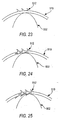
- Figs. 23-25 show a progression of three cuts being performed on a single suture that is being rotated to form a series of off-set barbs 512.
- the blades 502 cut a series of barbs 512.
- the suture material 510 is rotated as shown in the progression from Fig. 23 to Fig. 25 , the barbs are formed around the longitudinal axis of the suture 510.
- the movement of the suture can be optimized to increase or decrease space between the barbs both circumferentially and longitudinally.
- Other elements that can lead to optimization of the barb profile include the rotation speed of the cutting mechanism 500, the speed of longitudinal movement of the suture, and the speed of suture rotation. The timing of all of these can be varied to produce a desired barb profile and to avoid impinging previously cut barbs.
- This method produces barbs 512 which spiral about the central axis of the suture 510 without the need to twist the suture material as discussed above.
- a further example of the present disclosure is a drop-in blade cutter head assembly 600 as shown in Figs. 26 and 27 .
- the cuter head assembly 600 includes a cover 602.
- the cover 602 may include a compressible material 604 that applies a compression force to the back of the blades 608 which are inserted into a series of blade slots 606 and formed in the base 610.
- the compressive material 604 may run the entire length of the cover 602.
- the blade slots 606 are cut at an angle 0 to an exterior surface 612 of the base 610.
- the blades 608 may include a machined angled flat 614.
- the angle of the angled flat 614 has an angle ⁇ formed at a desired angle to the longitudinal axis of the blade 608 and which corresponds to the angle ⁇ at which the slots 606 are formed in the base 610.
- the angled flat 614 works in concert with the slots 606 and the compressible material in the cover 602 to ensure that the blades 608 are maintained at a desired angle to the base 610.
- blades 608 are inserted into each or substantially all of the slots 606.
- the cover is secured over the blades to hold the blades 608 in place.
- the cutter head may then be used in conjunction with a variety of barb cutting machines as described herein, including the 3-axis robot, and the apparatus shown in Fig. 10 .
- the drop in blades 608 may be sectioned from blade stock as shown in Figs. 28-30 .
- Blades 608 can be sectioned from blade stock so that the blade bevel is up or down.
- Blade bevel up means that the facet 616, which forms the cutting surface of the blade 608 faces away from the suture while cutting.
- Blade bevel down means that the facet 616 faces the suture when cutting.
- the blades may be sectioned from circular blade stock as shown in Fig. 30 .
- the resulting blade has a small radius to the cutting edge 618.
- One advantage of the blade 608 with radius cutting edge 618 is that it allows the cutting cycle to be initiated from either side of the suture.
- the radius cutting edge 618 also allows for both a forward and a backward cutting pass as shown in Figs. 31-33 .
- the blade is positioned to the side of the suture 620, and has a motion in direction 630.
- Fig. 32 shows the barb being formed during a forward cut while the blade 608 is moving in the forward direction 630.
- Fig. 33 shows a second barb 622 being formed on the suture 620 during a backward cut or while the blade 608 is moving in the backward direction 632.
- Another aspect of the present disclosure is a fluid jet cutting system that uses high-pressure liquid to form one or more barbs in the suture material.
- a fine spray of high-pressure fluid can be used in combination with, for example the 3-axis robot discussed above, to controllably cut barbs into suture material in a fashion similar to the use of the blades 608.
- the cross section shape of the fluid jet and its movement are used to control the formation and shape of the barbs. For materials that are likely to absorb water alternative fluids are considered suitable. Further, timing of the cuts can be used to optimize the depth of the barb and prevent cutting through the material.
- the planetary cutter 700 comprises two or more cylinders 708 with a cutting blade/edge 706 spirally oriented about the cylinder 708.
- the cylinders rotate about their own axes 710 as well as the axis of the suture 712.
- One advantage of the planetary cutter system 700 is that it allows for the cutting of a helical array of barbs without twisting the suture 702 before cutting.
- Opposing forces of cylindrical cutters 708 stabilize the suture 702 without the need for an additional vise apparatus.
- Three or more cylindrical cutters 708 may be used.
- opposing barb segments may be formed by engaging another planetary cutter 700 having appropriate cylindrical cutters 708 having spiral cutting edges 706 that rotate in an opposing direction to the original cylinders.
- the planetary cutter 700 may also comprise a ring gear (not shown) to apply rotational force to the cutters 708. Further, the ring gear may be driven in such a manner that the planetary cutter 700 traverses the longitudinal axis of the suture to form barbs of a desired length of suture without movement of the suture. Alternatively, the planetary cutter 700 may be stationary with the suture 702 being drawn through the rotating cutters 708. These and other variations of the planetary cutter 700 are possible.
Landscapes
- Life Sciences & Earth Sciences (AREA)
- Health & Medical Sciences (AREA)
- Engineering & Computer Science (AREA)
- Mechanical Engineering (AREA)
- Surgery (AREA)
- Forests & Forestry (AREA)
- Molecular Biology (AREA)
- Medical Informatics (AREA)
- Heart & Thoracic Surgery (AREA)
- Animal Behavior & Ethology (AREA)
- General Health & Medical Sciences (AREA)
- Public Health (AREA)
- Veterinary Medicine (AREA)
- Biomedical Technology (AREA)
- Nuclear Medicine, Radiotherapy & Molecular Imaging (AREA)
- Materials For Medical Uses (AREA)
- Surgical Instruments (AREA)
Abstract
Description
- The invention relates to a method for forming barbs on a filament.
- In the prior art, it is well known that surgical and traumatic wounds are typically closed with a filament introduced into the tissue by a needle attached to one end. Closure of the wound and holding tissues together supports healing and re-growth. What is typically used for this procedure is known as a suture.
- A barbed suture is a one-way suture which allows passage of a needle-drawn suture in one direction through tissue, but not in the opposite direction. A barbed suture is generally an elongated body having a pointed leading end and a plurality of axially and circumferentially spaced barbs on the exterior surface of the elongated body.
- In closing a wound with a barbed suture, the suture is passed through tissue at each of the opposed sides of a wound. Suture pairs are formed in which trailing ends of sutures are positioned generally in alignment at opposite sides of the wound. On insertion of each suture, the needle is pushed to extend out of the tissue at a point laterally remote from the wound, then the needle is pulled out to draw the suture to the desired position. The suture may then be severed from the needle or inserted again. (Note that methods of using barbed sutures are disclosed in copending
U.S. Patent Application No. 09/943,733 , "Method of Forming Barbs on a Suture and Apparatus for Performing Same," published underUS 2003/004126 A1 ) These methods are also described in International Patent Application,PCT/US02/27525 published underWO 03/017850 A2 - In some circumstances of tissue repair, a random configuration of barbs on the exterior of the suture is preferred. With as many barb angles as possible, superior wound holding may be achieved. However, in other circumstances where the wound or tissue repair needed is small, a small suture is preferable. A thin suture may require a reduced number of barbs on the exterior of the suture.
- In other circumstances the use of two-way barbed suture is preferable. A two-way barbed suture is one that has barbs permitting passing of the suture in one direction over a portion of the suture and barbs permitting passing of the suture in a second direction over another portion of the suture. Such an arrangement permits the passage of the suture through the tissue until the second set of barbs abut the tissue. Because the first set of barbs cannot be passed backward through the tissue and the second set of barbs cannot pass through the tissue, a firm closing stitch can be easily accomplished.
- Additional methods of cutting barbs on a suture filament have been proposed (see e.g.
U.S. Patent No. 5,931,855 to Buncke ). - It is seen from the foregoing that there is a need for an apparatus for cutting barbs in two directions on the exterior of sutures with a minimum of difficulty and in a precise, reliable and relatively economic fashion so as to allow for the wide spread commercialization of such sutures. Such an apparatus should also be able to vary the size of the barbs, their location and depth to allow for variation thereof and virtuality of their application. The apparatus should be able to cut a plurality of barbs positioned depending on the number of barbs needed. The configuration of the apparatus should also be variable depending upon, among other things, the type barbs being cut and the type of filament material, both of which relate to the type tissue being repaired. The apparatus should further be comprised of a series of components each of which facilitates the cutting of the barbs, these components being variable in configuration depending upon the desired features of the barbs to be cut.
- The present invention relates to a method for cutting barbs into a suture, as specified in
claim 1. - These and other objects and characteristics of the present invention will become apparent from the further disclosure to be made in the detailed description given below.
-
-
Fig. 1 , depicts a perspective view of a collet with three jaws. -
Fig. 2 , depicts a front view of a chuck with two jaws. -
Fig. 3 , depicts a profile view of a filament holder. -
Fig. 4 , depicts a top view of a filament holder. -
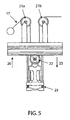
Fig. 5 , depicts a perspective view of a filament tensioner. -
Fig. 6 , depicts a perspective view of a cutting assembly with magnified view. -
Fig. 7 , depicts a collet equipped with a biased tensioner. -
Fig. 8 , depicts a rotational barb cutter mounted on a shaft. -
Fig. 9 , a perspective view of the cutting assembly and the in-feed and out-feed collets. -
Fig. 10 , depicts a perspective view of the apparatus. -
Fig. 11 , depicts an underside perspective view of the cutter. -
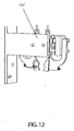
Fig. 12 , depicts a close-up perspective view of the grasping tool. -
Fig, 13 , depicts a close-up perspective view of the out-feed collet and the cutter. -
Fig. 14 , depicts a close up view of the cutting assembly, and the in-feed and out-feed collets. -
Fig. 15 , depicts a close up view of the apparatus. -
Fig. 16 , depicts a suture vise. -
Fig. 17 , depicts a 4-bar linkage system; -
Fig. 18 , depicts a 4-bar linkage barb cutter. -
Fig. 19 , depicts a 3-axis robot. -
Fig. 20 , depicts an exemplary movement series of a 3-axis robot. -
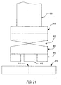
Fig. 21 , depicts a close up view of a cutter head according to the present invention. -
Fig. 22 , depicts a cutter mechanism. -
Figs. 23-25 , depict the formation of barbs on a suture using the cutter mechanism ofFig. 22 . -
Fig. 26 , depicts a cutter head. -
Fig. 27 , depicts a cross-section view of the cutter head ofFig. 26 . -
Fig. 28 , depicts a top view of a blade. -
Fig. 29 , depicts a side view of the blade ofFig. 28 . -
Fig. 30 , depicts a top view of a blade. -
Figs. 31-33 depict a two direction cutting motion using the blade ofFig. 30 . -
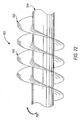
Fig. 34 , depicts a planetary cutting mechanism. - The apparatus as shown in
Fig.10 comprises afilament supply 101. The filament supply is preferably spool as shown inFig. 10 . Thefilament supply 101 may optionally be motor operated. Afilament 17 from thefilament supply 101 is threaded through a tensioner 20, as show inFig. 5 . From the tensioner 20, the filament is threaded to an in-feed collet 1. The filament is then threaded through an out-feed collet 1a, and tensioned by the tensioner 20. The tensioned filament is held between the closed in-feed and out-feed collets feed collets bed 10, which supports the filament during the cutting process. The filament is held firmly by chuck, 3, of the in-feed and out-feed collets when closed as shown inFig. 1 . The cuttingassembly 102 is then arranged to cut the barbs. - The cutting
assembly 102 comprises a plurality ofdirectional feed motors 103 that operatedrive screws 108 for moving thecutters 106 longitudinally along the filament. Preferably thedirectional feed motors 103 are stepper motors which can accurately control the location of the cutting heads 106, shown inFig. 11 . The cuttingassembly 102 also comprises a cuttingmotor 109 for articulating thecutters 106 and aheight adjusting motor 110. The various motors permit the independent motion of the cutters along the vertical, longitudinal, and perpendicular directions relative to the filament. The motors may further move in varying degrees of motion relative to the other motors to enable the barbs to be cut in various lengths, depths, and shapes. - Preferably, the
cutters 106 are oscillated to effect a cutting motion. This may be performed as shown inFig. 11 , through the use of an offsetcoupling 111 connected to the shaft of the cuttingmotor 109 and apin 112 attached to thecutters 106. As the cuttingmotor 109 turns, the offsetcoupling 111 forces alink 113 to impart a force on thecutters 106. This force propels the cutters in a direction substantially perpendicular to the longitudinal direction of the filament. To ensure that only linear motion is imparted on thecutter 106, slidingrams 114 are used. Slidingrams 114, when used in conjunction with thepin 112, and the offsetcoupling 111 assist in transferring any rotational motion imparted on the cutter by thecutter motor 109 to linear motion and prevent any rotational force to be applied to thecutters 106. In effect thecutters 106 saw into the filament. - The
height adjusting motor 110 insures that thecutters 106 are properly positioned over the filaments for cutting. Theheight adjusting motor 110 also lowers thecutters 106 during the cutting of the barbs to create a barb of a desired depth into the filament. Again, due to the precise nature of the movements, a stepper motor is preferably used. - In operation, a
first cutter 106 is operated by a firstdirectional feed motor 103 that moves thefirst cutter 106 in a first direction along the longitudinal axis of the filament. A seconddirectional feed motor 103 moves asecond cutter 106 in an opposite direction along the longitudinal axis of the filament. And a thirddirectional feed motor 103 controls the movement of the graspingtool 107. - During the cutting of barbs, the
directional feed motors 103 may move thecutters 106 linearly along the filament to force the barb away from the filament which gives the barb better holding power when in use. - After the barbs are cut onto the filament, the filament is advanced, so that the next suture may have barbs cut therein. The advancement method may comprise a simple motor operated drum and spool (not shown) as the filament supply, or preferably a grasping
tool 107 operated by adirectional feed motor 103, and driven by adrive screw 108 as seen inFigs. 12 and14 . The graspingtool 107 grasps an end of the filament that protrudes from the out-feed collet 1a. The graspingtool 107 is then advanced away from the out-feed collet 1a by thedirectional feed motor 103. Upon reaching a specified distance the out-feed collet 1a closes and asevering blade 105 cuts the filament to produce the suture. - The opening and closing of the grasping tool may be performed in a variety of ways including, but not limited to electromagnetic relays, pneumatic actuation, and hydraulic actuation.
- The sutures, once cut, may be packaged for later application of needles or hooks or a hook attachment device (not shown) may immediately place hooks on the suture before packaging. In the latter scenario, a hook is attached to the end of the filament that protrudes from the
out feed collet 1a while the barbs are being cut into the filament. After the barbs are cut, the graspingtool 107 draws the filament out to be cut to length and the second hook is applied after cutting. The graspingtool 107 then releases the completed suture for later packaging. - It is preferable that the cutting of the barbs occurs in two opposite directions on the filament, as the barbs are intended to allow movement of the suture in only one direction. Having two opposing sections of barbs, the surgeon or medical personnel placing the suture can insure that the suture will not come undone once placed. Accordingly, the apparatus allows for cutting of barbs in two opposing longitudinal directions of the filament, without the need to reverse the filament or the cutting blades.
- Typically, the cutting
assembly 102 has twocutters 106, one for cutting barbs facing a first direction and one for cutting barbs facing a second direction. In instances where a long section of barbs is desired, thecutters 106 may be moved by thedirectional feed motors 103 after cutting the first set of barbs to initiate a second or more sets of barbs to create a seamless transition from section to section of the barbs. In such instances it may become necessary to cut two or more sections of barbs in a first direction, advance the filament, and then cut two or more sections of barbs in the second direction. - The
cutter 106 may be formed of a plurality of cuttingblades 115 as shown inFig. 11 . While in the preferred example they resemble those described with respect toFig. 6 other cutting blades may also be used. - The
cutters 106 and theiroperational motors tracks 118 which limit the friction that must be overcome by thedirectional feed motor 103 to move thecutter 106. In a preferred example, the cutter is mounted on two bearingtracks 118 connected by aplate 116. Afollower 117 is mounted on theplate 116, thedrive screw 108 is threaded through thefollower 117. Thefollower 117 has internal threads matching those of thedrive screw 108. Thedirectional feed motor 103 in turn drives thedrive screw 108, which in turn acts upon thefollower 117 and the attachedplate 116 to position thecutter 106. Thedirectional feeds 103 are preferably stepper motors although other motors may be used. The stepper motor allows for finite control of the directional feed necessary to achieve the desired finish to the suture. By use of the stepper motor the exact position of thecutters 106 relative to thefilament 17 can be accurately and repeatably ascertained. Thecutters 106 can be manipulated by the barb cutting apparatus to enable a wide variety of shapes of barbs to be cut into thefilament 17. - In
Figs 3 and 4 , aholder 10 for securing a filament is shown. Theholder 10, secures the suture from lateral movement while barbs are cut into the filament. The holder provides a uniform profile for the cutting step and spreads the retention force along the length of thefilament 17. The spreading of the retention force avoids acute stresses that can damage thefilament 17 during the cutting process. The holder is preferably comprised of abed 11, and the bed is preferably made of steel or other machinable metal. Alternatively, the bed could be made of plastic, glass, ceramic or any other material suitable for the purpose. The bed surface is preferably machined flat and operates as a working surface for the cuttingassembly 102. The bed has achannel 12 machined into the exposed surface of the bed. The diameter ofchannel 12 is preferably the same as or slightly greater than the diameter of the suture material to be cut. The depth ofchannel 12 is preferably shallower that the diameter of the filament into which barbs are to be cut. Along the bottom of thechannel 12 are a series oforifices 14. Each orifice is preferably connected in common to abore 15. Thebore 15 is connected to a vacuum or suction means 13 for drawing a vacuum on thebore 15 and theorifices 14. The vacuum means 13 for drawing a vacuum on thebore 15 and the orifices may simply be a tube or pipe connected to a vacuum source as shown inFig. 3 . Such a tube may require afastener 16 for connection of the vacuum means to the holder. - In operation,
filament 17 is drawn throughchannel 12 ofbed 11 of theholder 10 substantially covering theorifices 14. Suction is then applied to the vacuum means 13. The vacuum produced by the suction translates to theorifices 14, which in turn holds thefilament 17 rigidly in place. Once the filament is held rigidly in place a cutting operation can be commenced to cut barbs into thefilament 17. - A
collet 1 is shown inFig. 1 . Thecollet 1 holds a filament that has been threaded therethrough. Thecollet 1 secures the filament firmly without damaging the filament even during twisting. Thecollet 1 is comprised of asupport 2 and achuck 3.Chuck 3 has a plurality of articulatingjaws 4, which may be opened and closed to facilitate the passing of a filament through thecollet 1. Thejaws 4 close to hold a filament. Thejaws 4 are preferably finely machined so that they can close tightly around the filament without damaging it. Thechuck 3 may house two jaws positioned, for example, 180° apart as shown inFig. 2 , or three jaws positioned approximately 120° apart as shown inFig.1 , or more. - In the three jaw configuration as shown in
Fig. 1 it is preferable that each jaw have a substantially flatgripping surface 5 which enables all threejaws 4 to simultaneously grip thefilament 17. In the two-jaw configuration it is preferable that eachjaw 4a have a concavegripping surface 5a. The concave gripping surface is sufficiently shallow to allow thejaws 4a to firmly hold the filament. The positioning and configuration insures that thejaws 4a apply even pressure to the filament and have good holding power without damaging thefilament 17. Additionally, the jaws may be formed of a material that prevents contamination of thefilament 17. - The
jaws - The
chuck 3 of thecollet 1 is preferably rotatable. Rotation of thechuck 3 facilitates the imparting of twist to a filament held by thejaws assembly 102 is able to cut in a single pass barbs on the filament that are offset from one another when the filament is untwisted. Offset barbs may also be achieved by cutting of the untwisted filament, and then rotating the collet to rotate the filament into a twist. Filaments are known to retain a twist conformation after twisting - a characteristic which may be enhanced by an annealing step. Annealing entails the application of heat to the suture strand and may be useful in the long term preservation of a specific suture conformation. Annealing may be of particular interest where it is desired to generate and maintain a helical array of barbs by deforming, e.g. by twisting a suture, either before or after cutting a series of barbs in an unconstrained suture filament. Annealing may further be necessary to ensure stable product geometry during long term storage and/or high temperature exposure. - If the suture is to be annealed after deformation, annealing should be performed as soon as possible after the suture has been placed in the desired conformation. Generally, the annealing temperature should be above the glass transition temperature but below the melting temperature of the polymer to achieve optimum results. Annealing may also be used as a pre-processing step for the suture material that adds a conformation that is useful later in the manufacture of a barbed suture.
- Alternatively, or in conjunction with annealing, the application of a non-linear packaging method may further improve long term retention of suture geometries such as a twist. Several packaging methods are available that employ a non-linear product arrangement such as a raceway. By packaging a suture in a non-linear fashion, the ability of the suture's geometry to return to its natural state is resisted. This may be of particular interest where the method of obtaining a helical array of barbs leaves significant internal stresses within the product that may have a tendency to relax over time or when subjected to moderate or extreme storage conditions.For further discussion of the practice of twisting the filament before and after cutting barbs see U.S. Patent Application
US 2003/0041426 A1 . The rotation of the collet is preferably actuated by an electrical motor. However pneumatic, or hydraulic means could also be employed. - Preferably the barb cutting apparatus comprises two collets an in-
feed collet 1, and an out-feed collet 1a. Either one or both of these collets may be rotatable. However it is preferable that at least the out feed collet is rotatable. Further, it is preferable that the out-feed collet 1a be rotatable in both afirst direction 7 andsecond direction 8. This facilitates both the imparting of twist on a filament and the removing of twist from the filament. However, there may exist applications, and filament fibers for which imparting and maintaining twist is preferable for storage or other applications. In such applications the filament can be twisted and untwisted as desired, either before or after cutting. - The present disclosure further relates to a tensioner 20 for tensioning a
filament 17. The tensioner 20 comprisespulleys 21 and 22. The pulleys consist ofstationary pulleys movable pulley 22. The tensioner 20 ensures that thefilament 17 is constantly under a relatively uniform tension throughout any of the advancement, twisting and barb cutting steps regardless of their sequence. - The filament is preferably run over a first
stationary pulley 21a, under amovable pulley 22, and then over a secondstationary pulley 21b. In a preferred example, asprings 23 act as limiting devices stopping the movement of themoveable pulley 22 in afirst direction 25. The movable pulley is weighted, this weight tensions the filament as it is drawn through the collets by thegripping tool 107. The movement of the filament by thegripping tool 107 causes themovable pulley 22 to move in asecond direction 26. Accordingly, the length of travel of themovable pulley 22 is approximately equal to maximum length of a suture. Upon stopping movement in thesecond direction 26, thefilament supply 101 slowly rotates to allow the filament to be pulled away from thefilament supply 101 and in the direction of thestationary pulley 21 a. This allows themovable pulley 22 to move in thefirst direction 25 until contacting thesprings 22. Thefilament supply 101 is most preferable operated by a stepper motor which can gradually advance the filament until themovable pulley 22 contacts thesprings 23. Sensors may be added to stop the motor when the movable pulley reaches a predetermined position. - In use, the tensioner 20 ensures that
filament 17 which spans from an in-feed collet to an out-feed collet is properly tensioned. Tensioning is necessary to ensure that thefilament 17 can be properly twisted either before or after having barbs cut therein. Tensioning of thefilament 26 further assists in preventing the filament from moving during the cutting process and insures proper alignment of thefilament 17. The initiation of the supply of the filament by the rotation of thefilament supply 101 is not begun until after the infeed collet 1 has closed on the filament. This insures that there is always tension on the filament. - The present disclosure still further relates to a
collet 40 having acollet tensioner 44. It is understood that when a filament is twisted, the length of that filament will be decreased. Accordingly, when the filament is firmly grasped at two ends the force required to twist the filament is transferred into a longitudinal tension force acting on the filament. If the force were of sufficient magnitude, the filament could break. To avoid this, at least one of thecollets 40 of the cutting apparatus may be equipped with acollet tensioner 44. Thecollet tensioner 44 may be comprised of a simple spring as shown inFig. 7 . In thecollet 40 shown inFig 7 , thesupport 41 of thecollet 40 is rotatable about apin 46. The pin passes through thesupport 41 and thecollet base 45. Thecollet tensioner 44 acts against the base 45 in the longitudinal direction of a filament threaded through thechuck 43 housed in thecollet 40. The tension imparted on the filament bycollet tensioner 44 may be adjusted byscrew cap 5 which increases or decreases an initial spring tension imparted on thecollet 40. This adjustment enables the apparatus to be useful for a wide variety of filament materials. - In operation, when the filament is twisted, the force of the shortening causes the
collet 40 to be pulled in the longitudinal direction of the filament. Thecollet tensioner 44 allows for thecollet 40 to move in that direction when sufficient force is imparted on thecollet 40 to overcome the resisting spring force of thecollet tensioner 44. Thepin 46 provides an axis about which thecollet 40 can rotate. This movement insures that the force imparted on the filament never exceeds the spring force of thecollet tensioner 44. Accordingly, the spring force of thecollet tensioner 44 can be regulated to insure that the filament is never tensioned to the point of breaking. - As shown in
Fig. 6 , the present disclosure relates to acutting blade 30 for use in a method according to the invention for cutting barbs into a filament.Fig. 6 shows a cutting blade having a sharply honededge 31. This is the primary cutting edge of the cutting assembly and is used for the initial cutting of a barb in a filament. Following the first edge is asecond edge 32. The second edge is preferably blunted, textured or rounded, as shown in the magnified view of the cuttingassembly 30,Fig. 6 . The textured and blunted features of cuttingblade 30 act to roughen the interior surfaces of the barb section of the filament. This is preferable because it has been observed that a roughened texture on the interior surface of a barb imparts greater holding ability. This gripping ability insures that the suture is less likely to slip when threaded through tissues by a surgeon or other medical personnel. Alternatively, cutting blades with ends that are arcuate can create an arcuate shape at the base of the barb so as to reduce the sheering stress focused at the vertex of the barb. - According to the invention, the cutting blade is drawn across and into the filament to be cut. As such, the sharply honed
first edge 31 cuts the barb in the filament to the desired depth and at the desired angle to the filament. Thesecond edge 32 is subsequently drawn along the previously cut barb and roughens the interior surfaces of the barb. - In yet another aspect of the present disclosure the cutting blade is held by a robotic arm and performs the cutting of the filament in an articulated, motor controlled action. The robotic arm holds a plurality of cutting blades and locates the cutting blades over the filament. In one aspect of the robotic arm disclosure, the cutting blades oscillate in a cutting motion while being lowered onto the filament by the robotic arm. Further, the robotic arm may angle the cutting blades to form the barbs on the filament.
- Another aspect of the present disclosure relates to a
cutter 80 that is comprised of a series of cuttingdisks 81 connected to ashaft 82, as shown inFig. 8 . The cutting disks have an angled tab extending from them. The tab is the cutting surface of the disk. The tab is angled at least 90 degrees from the disk. This angling allows for the barb to be displaced vertically from the filament which increases its gripping power when used. A plurality of disks are attached to a single shaft separated by spacers (not shown). On a single shaft disks with tabs facing in opposite directions can be attached to enable the cutting of barbs in both directions in a single operation. Alternatively, two cutters could be used, one for cutting the barbs in each direction. The tabs of the cutting disks are offset relative to one another such that the cutter can be positioned over a filament in which barbs are to be cut without initially contacting the filament. It is preferable that thecutter 80 makes one rotation to cut all of the barbs for a single suture, however, it may be necessary in certain applications to make more rotations particularly where a large section of suture is to be given barbs of a particular orientation. Finally, thetabs 83 may be given a variety of cutting shapes and attributes, these include but are not limited to cup shaped blades, tear dropped shaped blades, and roughed blades, as shown inFig. 6 . - Another embodiment of the present disclosure is the
cutting mechanism 200 shown inFig 16 , which comprises avise bed 202 having no moving parts. InFig. 16 thesuture 204 is held in semicircular groove, not shown, formed on one side of thevise bed 202 to prevent thesuture 204 from moving laterally during the cutting operation. Thesuture 204 is tensioned by moving thevise bed 202 vertically while the suture is held in place and prevented from slipping by the first and second collets 206a and 206b. Thevise bed 202 may substantially conform to the shape of the arc created by the tensioning of thesuture 204. - In a further embodiment of the present disclosure, the
vise bed 202 and cuttingheads 208 are mounted to amoveable plate 210. This reduces the number of individual tolerances and thereby the tolerance stack up between thevise bed 202 andblades 212. - The
movable plate 210 is movable in at least two directions, for example vertical and horizontal. Movement in the vertical direction tensions thesuture 204 while movement in the horizontal directions allows for cutting to occur across the span of thesuture 204, between the first and second collets 206a and b. Movement of the cuttinghead 208 relative to plate 210 in a direction perpendicular to the horizontal direction moves theblades 212 across thesuture 204 and allows the blades to form the barbs. - In one example, to avoid damaging the
suture 204, thevise bed 202 may begin at the outfeed side near the second collet 206b and move towards the infeed side near the first collet 206a. In the example shown inFig. 16 two cuttingheads 208 are used, each with a single fixedblade 212, that is moved in the direction perpendicular to the longitudinal axis of thesuture 204 to cut the barbs. - The
blades 212 can undertake a variety of motions in forming the barbs on thesuture 204. One example of the blade motion is substantially square. In the square or rectangular motion theblade 212 traverses perpendicular to the longitudinal axis of thesuture 204 to cut a barb. Theblade 212 is then moved in the horizontal direction along the longitudinal axis of the suture to a predetermined and customizable point. Theblade 212 then is drawn back across the suture but at a height that prevents theblade 212 from engaging thesuture 204 and the formation of a barb. One skilled in the art will recognize that a variety of methods could be employed to ensure theblade 212 cuts while moving in one direction but does not cut when moving in a substantially opposite direction. For example a cam or ramp system could be employed to ensure that the height of theblade 212 is altered when changing directions in its movement perpendicular to the longitudinal axis of thesuture 204. Other examples include motor controlled indexing screws that alter the height of themovable plate 210 depending upon the direction of travel of the blades. In addition, the blade may also be designed to accommodate two-direction cutting. In such an example when performing the second motion perpendicular to the longitudinal direction of thesuture 204, theblade 212 is not raised above the suture. An example of a blade that can be used for two-direction cutting is shown inFig. 30 , which will be discussed in detail below. - The above-described
cutting mechanism 200 has several advantages including a decrease in the tolerance stack up for the various parts as they are mounted on a singlemovable plate 210. Further, the use of tension to hold thesuture 204 in place may prevent damage to sutures made of certain suture materials that may occur when barbs are cut using a vise, as discussed above, that uses compressive forces to secure the suture. And as there is a reduction of moving parts the accuracy of thecutting mechanism 200 is improved. - Another advantageous example of the present disclosure is shown in
Figs. 17 and 18 and includes ablade 312 mounted on a 4bar mechanism 310. The 4-bar mechanism is connected to a series of gears that provide a rotating motion of thecutter head 308 to form barbs on thesuture 304. The motion of alead screw 314 causes afollower gear 316 to propel the four-bar cutting system 300 along the longitudinal axis of the suture. The cutting head's 4-bar linkage 310 is connected to thelead screw 314 and thefollower gear 316 by aspline gear system 318. The spline gear system imparts rotational force to the 4-bar linkage 310 that allows multiple cuts to be made in succession while the cuttinghead 308 is moved down the length of thesuture 304. - The cutting
head 308 is moved in a substantially circular motion describing anarc 306 by thespline gear system 318 and connected 4-bar linkage. One direction of movement of theblade 312 is substantially perpendicular to the longitudinal axis of thesuture 304 for cutting barbs in succession, while the rotational movement of theblade 312 is at a desired angle to thesuture 304. Theblade 312 is angled approximately at the same angle at which the barb is to be formed as shown inFig. 18 . Because the motion of blade is permanently linked with motion of the four bar linkage and the lead screw the cutting head the four-bar cutting system 300 has the ability to cut barbs at high speeds. - In
Figs. 19, 20 , and21 yet another example of the present disclosure is shown. InFig. 19 , a 3-axis robot 400 using a cartesian coordinate arrangement directly controls the motion of the cuttinghead 402 in a "fixed" fashion (i.e., with minimal vibratory motion). - The
robot 400 includesarm 404 for moving the cuttinghead 402 in the x-direction,arm 406 for moving the cuttinghead 402 in the y-direction, andarm 408 for moving the cutting head in the z direction.Blades 410 are maintained in the cuttinghead 402 withspacers 412 that maintain a consistent distance between the top of thevise 414 and the ends of theblades 410. - In one example shown in
Fig. 20 blades 410 cut barbs in a single pass oversuture 416. First theblades 410 are lowered to a point at which they can contact thesuture 416, as shown inmovement 420. Then the cuttinghead 402 is moved slightly in the x-direction while the cuttinghead 402 is brought across thesuture 416 moving substantially in the y-direction, as shown inmovement 422 ofFig. 20 . The cutting head is then brought back over the suture in movement 424 in preparation for the next cut as shown inFig. 20 . Once all cuts have been made for barbs in one direction, therotational activator 418 spins the cuttinghead 402 180° inmovement 426 to produce barbs in the opposing direction as shown inmovements 428. - By utilizing a
spring 420 between the z-axis arm 408 and the cuttinghead 402, tolerances for the z-axis arm can be decreased because blade positioning is maintained by thespacers 412 on the bottom of the cuttinghead 402 that contact the top of thevise 414. Alternately, the spring and cutting head spacers could be removed to allow the z-axis arm alone to control depth of cut. - A further example of the present disclosure is a corkscrew rotating cutting mechanism as shown in
Fig. 22 . Thecutting mechanism 500 is formed of a single piece and can be rotated in acutting direction 506. The cutting edges 502 are formed in a spiral around a central rod orshaft 504. Thecutting mechanism 500 may be designed so that in use it has only a short period of time that it is in contact with a suture. For example, while being constantly rotated thecutting mechanism 500 may be raised and lowered on to a suture material to form barbs during just a small portion of its rotation. When thecutting mechanism 500 is lifted, the suture material may be advanced to allow the cutting mechanism to cut barbs in a new location on the suture material or a new suture. Thecutting mechanism 500 may also be synchronized with a suture that is continuously moving to produce a continuous feed of barbed suture material. -
Figs. 23-25 show a progression of three cuts being performed on a single suture that is being rotated to form a series of off-setbarbs 512. By controlling the speed of thecutting mechanism 500 and raising and lowering thesuture 510 onto theblades 502, theblades 502 cut a series ofbarbs 512. If thesuture material 510 is rotated as shown in the progression fromFig. 23 to Fig. 25 , the barbs are formed around the longitudinal axis of thesuture 510. The movement of the suture can be optimized to increase or decrease space between the barbs both circumferentially and longitudinally. Other elements that can lead to optimization of the barb profile include the rotation speed of thecutting mechanism 500, the speed of longitudinal movement of the suture, and the speed of suture rotation. The timing of all of these can be varied to produce a desired barb profile and to avoid impinging previously cut barbs. This method producesbarbs 512 which spiral about the central axis of thesuture 510 without the need to twist the suture material as discussed above. - A further example of the present disclosure is a drop-in blade
cutter head assembly 600 as shown inFigs. 26 and 27 . Thecuter head assembly 600 includes acover 602. Thecover 602 may include acompressible material 604 that applies a compression force to the back of theblades 608 which are inserted into a series ofblade slots 606 and formed in thebase 610. Thecompressive material 604 may run the entire length of thecover 602. - In one example the
blade slots 606 are cut at anangle 0 to anexterior surface 612 of thebase 610. As shown inFigs. 28 and 29 , theblades 608 may include a machined angled flat 614. The angle of the angled flat 614 has an angle α formed at a desired angle to the longitudinal axis of theblade 608 and which corresponds to the angle ∅ at which theslots 606 are formed in thebase 610. The angled flat 614 works in concert with theslots 606 and the compressible material in thecover 602 to ensure that theblades 608 are maintained at a desired angle to thebase 610. - In practice,
blades 608 are inserted into each or substantially all of theslots 606. The cover is secured over the blades to hold theblades 608 in place. The cutter head may then be used in conjunction with a variety of barb cutting machines as described herein, including the 3-axis robot, and the apparatus shown inFig. 10 . - The drop in
blades 608 may be sectioned from blade stock as shown inFigs. 28-30 .Blades 608 can be sectioned from blade stock so that the blade bevel is up or down. Blade bevel up means that thefacet 616, which forms the cutting surface of theblade 608 faces away from the suture while cutting. Blade bevel down means that thefacet 616 faces the suture when cutting. - Alternatively, the blades may be sectioned from circular blade stock as shown in
Fig. 30 . The resulting blade has a small radius to thecutting edge 618. One advantage of theblade 608 withradius cutting edge 618 is that it allows the cutting cycle to be initiated from either side of the suture. - The
radius cutting edge 618 also allows for both a forward and a backward cutting pass as shown inFigs. 31-33 . InFig. 31 , the blade is positioned to the side of thesuture 620, and has a motion indirection 630.Fig. 32 shows the barb being formed during a forward cut while theblade 608 is moving in theforward direction 630.Fig. 33 shows asecond barb 622 being formed on thesuture 620 during a backward cut or while theblade 608 is moving in thebackward direction 632. - Another aspect of the present disclosure is a fluid jet cutting system that uses high-pressure liquid to form one or more barbs in the suture material. Using water jet cutting technology, a fine spray of high-pressure fluid can be used in combination with, for example the 3-axis robot discussed above, to controllably cut barbs into suture material in a fashion similar to the use of the
blades 608. The cross section shape of the fluid jet and its movement are used to control the formation and shape of the barbs. For materials that are likely to absorb water alternative fluids are considered suitable. Further, timing of the cuts can be used to optimize the depth of the barb and prevent cutting through the material. - Yet another example of the present disclosure is a planetary cylindrical cutter system as shown in
Fig. 34 . Theplanetary cutter 700 comprises two ormore cylinders 708 with a cutting blade/edge 706 spirally oriented about thecylinder 708. The cylinders rotate about theirown axes 710 as well as the axis of thesuture 712. One advantage of theplanetary cutter system 700 is that it allows for the cutting of a helical array of barbs without twisting thesuture 702 before cutting. - Opposing forces of
cylindrical cutters 708 stabilize thesuture 702 without the need for an additional vise apparatus. Three or morecylindrical cutters 708 may be used. In addition, opposing barb segments may be formed by engaging anotherplanetary cutter 700 having appropriatecylindrical cutters 708 havingspiral cutting edges 706 that rotate in an opposing direction to the original cylinders. - This method of barb formation allows access to the entire circumference of the suture. Breaks in
spiral blade 706 prevent barbs from being shaved off the surface of thesuture 702 after formation. Those skilled in the art will appreciate that theplanetary cutter 700 may also comprise a ring gear (not shown) to apply rotational force to thecutters 708. Further, the ring gear may be driven in such a manner that theplanetary cutter 700 traverses the longitudinal axis of the suture to form barbs of a desired length of suture without movement of the suture. Alternatively, theplanetary cutter 700 may be stationary with thesuture 702 being drawn through therotating cutters 708. These and other variations of theplanetary cutter 700 are possible. - While the invention has been described in connection with what is considered to be the most practical and preferred embodiment, it should be understood that this invention is not limited to the disclosed embodiments, but on the contrary, is intended to cover various modifications and equivalent arrangements included within the scope of the appended claims.
Claims (1)
- A method for cutting barbs into a suture, the method comprising
providing a cutting blade (30) with a sharply honed first edge (31),
drawing the first edge (31) across and into a suture to a desired depth and at a desired angle to cut a barb, and characterised by
subsequently drawing a blunted and roughened second edge (32) of the cutting blade (30) along the previously cut barb and thereby roughening the interior surface of the barb.
Applications Claiming Priority (2)
| Application Number | Priority Date | Filing Date | Title |
|---|---|---|---|
| US10/437,144 US7624487B2 (en) | 2003-05-13 | 2003-05-13 | Apparatus and method for forming barbs on a suture |
| EP20040752088 EP1622518B1 (en) | 2003-05-13 | 2004-05-13 | Apparatus for forming barbs on a suture |
Related Parent Applications (2)
| Application Number | Title | Priority Date | Filing Date |
|---|---|---|---|
| EP04752088.7 Division | 2004-05-13 | ||
| EP20040752088 Division EP1622518B1 (en) | 2003-05-13 | 2004-05-13 | Apparatus for forming barbs on a suture |
Publications (2)
| Publication Number | Publication Date |
|---|---|
| EP2335604A1 EP2335604A1 (en) | 2011-06-22 |
| EP2335604B1 true EP2335604B1 (en) | 2014-02-26 |
Family
ID=33417314
Family Applications (2)
| Application Number | Title | Priority Date | Filing Date |
|---|---|---|---|
| EP20040752088 Active EP1622518B1 (en) | 2003-05-13 | 2004-05-13 | Apparatus for forming barbs on a suture |
| EP10012437.9A Active EP2335604B1 (en) | 2003-05-13 | 2004-05-13 | Method for forming barbs on a suture |
Family Applications Before (1)
| Application Number | Title | Priority Date | Filing Date |
|---|---|---|---|
| EP20040752088 Active EP1622518B1 (en) | 2003-05-13 | 2004-05-13 | Apparatus for forming barbs on a suture |
Country Status (7)
| Country | Link |
|---|---|
| US (2) | US7624487B2 (en) |
| EP (2) | EP1622518B1 (en) |
| AT (1) | ATE533409T1 (en) |
| AU (1) | AU2004238371B2 (en) |
| CA (3) | CA2854710C (en) |
| ES (1) | ES2457542T3 (en) |
| WO (1) | WO2004100801A2 (en) |
Families Citing this family (77)
| Publication number | Priority date | Publication date | Assignee | Title |
|---|---|---|---|---|
| US6241747B1 (en) | 1993-05-03 | 2001-06-05 | Quill Medical, Inc. | Barbed Bodily tissue connector |
| US8795332B2 (en) | 2002-09-30 | 2014-08-05 | Ethicon, Inc. | Barbed sutures |
| US5931855A (en) | 1997-05-21 | 1999-08-03 | Frank Hoffman | Surgical methods using one-way suture |
| US7056331B2 (en) | 2001-06-29 | 2006-06-06 | Quill Medical, Inc. | Suture method |
| US6848152B2 (en) * | 2001-08-31 | 2005-02-01 | Quill Medical, Inc. | Method of forming barbs on a suture and apparatus for performing same |
| US6773450B2 (en) | 2002-08-09 | 2004-08-10 | Quill Medical, Inc. | Suture anchor and method |
| US20040088003A1 (en) | 2002-09-30 | 2004-05-06 | Leung Jeffrey C. | Barbed suture in combination with surgical needle |
| US8100940B2 (en) | 2002-09-30 | 2012-01-24 | Quill Medical, Inc. | Barb configurations for barbed sutures |
| US7624487B2 (en) | 2003-05-13 | 2009-12-01 | Quill Medical, Inc. | Apparatus and method for forming barbs on a suture |
| WO2005096955A1 (en) * | 2004-04-07 | 2005-10-20 | Tze Liang Woffles Wu | Surgical thread |
| US8236027B2 (en) * | 2004-04-07 | 2012-08-07 | Tze Liang Woffles Wu | Surgical thread |
| SG164370A1 (en) | 2004-05-14 | 2010-09-29 | Quill Medical Inc | Suture methods and devices |
| DE102004047974A1 (en) * | 2004-10-01 | 2006-04-06 | Ethicon Gmbh | Surgical hook |
| ITRM20070162A1 (en) * | 2007-03-27 | 2008-09-28 | Promoitalia Internat Srl | CARVING APPARATUS FOR SURGICAL THREADS |
| US8915943B2 (en) | 2007-04-13 | 2014-12-23 | Ethicon, Inc. | Self-retaining systems for surgical procedures |
| US8161618B2 (en) | 2007-09-17 | 2012-04-24 | Tyco Healthcare Group Lp | Method of forming barbs on a suture |
| US8777987B2 (en) | 2007-09-27 | 2014-07-15 | Ethicon, Inc. | Self-retaining sutures including tissue retainers having improved strength |
| US8916077B1 (en) | 2007-12-19 | 2014-12-23 | Ethicon, Inc. | Self-retaining sutures with retainers formed from molten material |
| US8771313B2 (en) | 2007-12-19 | 2014-07-08 | Ethicon, Inc. | Self-retaining sutures with heat-contact mediated retainers |
| US8118834B1 (en) | 2007-12-20 | 2012-02-21 | Angiotech Pharmaceuticals, Inc. | Composite self-retaining sutures and method |
| US8615856B1 (en) | 2008-01-30 | 2013-12-31 | Ethicon, Inc. | Apparatus and method for forming self-retaining sutures |
| EP2242430B1 (en) | 2008-01-30 | 2016-08-17 | Ethicon, LLC | Apparatus and method for forming self-retaining sutures |
| WO2009105663A2 (en) * | 2008-02-21 | 2009-08-27 | Angiotech Pharmaceuticals, Inc. | Method and apparatus for elevating retainers on self-retaining sutures |
| US8216273B1 (en) | 2008-02-25 | 2012-07-10 | Ethicon, Inc. | Self-retainers with supporting structures on a suture |
| US8641732B1 (en) | 2008-02-26 | 2014-02-04 | Ethicon, Inc. | Self-retaining suture with variable dimension filament and method |
| JP5619726B2 (en) | 2008-04-15 | 2014-11-05 | エシコン・エルエルシーEthicon, LLC | Self-retaining suture with bidirectional retainer or unidirectional retainer |
| US8961560B2 (en) | 2008-05-16 | 2015-02-24 | Ethicon, Inc. | Bidirectional self-retaining sutures with laser-marked and/or non-laser marked indicia and methods |
| US7967841B2 (en) * | 2008-06-02 | 2011-06-28 | Ethicon, Inc. | Methods for using looped tissue-grasping devices |
| AU2009319965B2 (en) | 2008-11-03 | 2014-11-06 | Ethicon Llc | Length of self-retaining suture and method and device for using the same |
| US8402621B2 (en) * | 2009-04-29 | 2013-03-26 | Covidien Lp | System and method for forming barbs on a suture |
| US9232954B2 (en) | 2009-08-20 | 2016-01-12 | Howmedica Osteonics Corp. | Flexible ACL instrumentation, kit and method |
| US8210085B2 (en) * | 2009-08-27 | 2012-07-03 | Ethicon, Inc. | Automated systems and methods for making braided barbed sutures |
| US9044224B2 (en) | 2010-04-12 | 2015-06-02 | Covidien Lp | Barbed medical device and method |
| US9700304B2 (en) | 2010-04-19 | 2017-07-11 | Gold Thread Llc | Filament implant system and method |
| ES2697515T3 (en) * | 2010-04-29 | 2019-01-24 | Ethicon Llc | High density self-retaining sutures |
| BR112012028331B1 (en) | 2010-05-04 | 2020-04-28 | Ethicon Endo Surgery Llc | self-retaining suture |
| US8945156B2 (en) | 2010-05-19 | 2015-02-03 | University Of Utah Research Foundation | Tissue fixation |
| US8858577B2 (en) | 2010-05-19 | 2014-10-14 | University Of Utah Research Foundation | Tissue stabilization system |
| CN103068323B (en) | 2010-06-11 | 2015-07-22 | 伊西康有限责任公司 | Suture delivery tools for endoscopic and robot-assisted surgery and methods |
| US8303881B2 (en) * | 2010-10-28 | 2012-11-06 | Covidien Lp | Suture containing barbs |
| CN103747746B (en) | 2010-11-03 | 2017-05-10 | 伊西康有限责任公司 | Drug-eluting self-retaining sutures and methods relating thereto |
| US8414612B2 (en) | 2010-11-08 | 2013-04-09 | Covidien Lp | Multifilament barbed suture |
| RU2580479C2 (en) | 2010-11-09 | 2016-04-10 | ЭТИКОН ЭлЭлСи | Emergency self-retaining sutures and packaging therefor |
| US8852214B2 (en) | 2011-02-04 | 2014-10-07 | University Of Utah Research Foundation | System for tissue fixation to bone |
| AU2012230716B2 (en) | 2011-03-23 | 2016-05-19 | Ethicon Llc | Self-retaining variable loop sutures |
| US9011133B2 (en) | 2011-04-29 | 2015-04-21 | Covidien Lp | Apparatus and method of forming barbs on a suture |
| US9687227B2 (en) | 2011-04-29 | 2017-06-27 | Covidien Lp | Apparatus and method of forming barbs on a suture |
| US8640331B2 (en) | 2011-05-31 | 2014-02-04 | Covidien Lp | Barbed sutures |
| US9241709B2 (en) | 2011-05-31 | 2016-01-26 | Covidien Lp | Barbed sutures |
| US20130172931A1 (en) | 2011-06-06 | 2013-07-04 | Jeffrey M. Gross | Methods and devices for soft palate tissue elevation procedures |
| US8715334B2 (en) | 2011-07-14 | 2014-05-06 | Boston Scientific Scimed, Inc. | Anti-migration stent with quill filaments |
| US9445803B2 (en) | 2011-11-23 | 2016-09-20 | Howmedica Osteonics Corp. | Filamentary suture anchor |
| US9427309B2 (en) | 2012-07-30 | 2016-08-30 | Conextions, Inc. | Soft tissue repair devices, systems, and methods |
| US9629632B2 (en) | 2012-07-30 | 2017-04-25 | Conextions, Inc. | Soft tissue repair devices, systems, and methods |
| US11957334B2 (en) | 2012-07-30 | 2024-04-16 | Conextions, Inc. | Devices, systems, and methods for repairing soft tissue and attaching soft tissue to bone |
| US10390935B2 (en) | 2012-07-30 | 2019-08-27 | Conextions, Inc. | Soft tissue to bone repair devices, systems, and methods |
| US11253252B2 (en) | 2012-07-30 | 2022-02-22 | Conextions, Inc. | Devices, systems, and methods for repairing soft tissue and attaching soft tissue to bone |
| US10835241B2 (en) | 2012-07-30 | 2020-11-17 | Conextions, Inc. | Devices, systems, and methods for repairing soft tissue and attaching soft tissue to bone |
| US10219804B2 (en) | 2012-07-30 | 2019-03-05 | Conextions, Inc. | Devices, systems, and methods for repairing soft tissue and attaching soft tissue to bone |
| US11944531B2 (en) | 2012-07-30 | 2024-04-02 | Conextions, Inc. | Devices, systems, and methods for repairing soft tissue and attaching soft tissue to bone |
| CN103144131B (en) * | 2013-03-20 | 2015-01-21 | 东华大学 | Self-locking type suture line preparation device and preparation method thereof |
| WO2014176270A1 (en) | 2013-04-22 | 2014-10-30 | Pivot Medical, Inc. | Method and apparatus for attaching tissue to bone |
| KR101550103B1 (en) * | 2013-11-07 | 2015-09-03 | 김춘동 | Thread cogs making machine and method for making thereof |
| US11583384B2 (en) | 2014-03-12 | 2023-02-21 | Conextions, Inc. | Devices, systems, and methods for repairing soft tissue and attaching soft tissue to bone |
| WO2016025329A1 (en) | 2014-08-15 | 2016-02-18 | Tepha, Inc. | Self-retaining sutures of poly-4-hydroxybutyrate and copolymers thereof |
| US9986992B2 (en) | 2014-10-28 | 2018-06-05 | Stryker Corporation | Suture anchor and associated methods of use |
| EP3085820B1 (en) | 2015-04-22 | 2017-12-20 | Sofradim Production | A method for forming a barbed suture and the barbed suture thus obtained |
| EP3085332B1 (en) | 2015-04-23 | 2019-02-27 | Sofradim Production | Package for a surgical mesh |
| US10206675B2 (en) | 2016-07-13 | 2019-02-19 | Ethicon Llc | Method and apparatus for fabricating self-retaining sutures with calibration |
| US11696822B2 (en) | 2016-09-28 | 2023-07-11 | Conextions, Inc. | Devices, systems, and methods for repairing soft tissue and attaching soft tissue to bone |
| US11547397B2 (en) | 2017-12-20 | 2023-01-10 | Conextions, Inc. | Devices, systems, and methods for repairing soft tissue and attaching soft tissue to bone |
| WO2019164853A1 (en) | 2018-02-20 | 2019-08-29 | Conextions, Inc. | Devices, systems, and methods for repairing soft tissue and attaching soft tissue to bone |
| US11272924B2 (en) | 2018-07-18 | 2022-03-15 | Arthrex, Inc. | Knotless closure sutures and methods of tissue fixation |
| CN111134748B (en) * | 2020-01-03 | 2021-06-15 | 浙江微度医疗器械有限公司 | Device and method for forming one-way or two-way barbs on suture |
| CN113069161B (en) * | 2021-03-18 | 2022-10-04 | 南京普立蒙医疗科技有限公司 | Improve barb stylolite cutting equipment of yields |
| WO2023167381A1 (en) * | 2022-03-04 | 2023-09-07 | 주식회사 현대메디텍 | Apparatus and method for producing biodegradable thread and biodegradable thread produced using same |
| CN115213947B (en) * | 2022-06-07 | 2024-04-19 | 南通华利康医疗器械有限公司 | Suture line barb processing mechanism |
Family Cites Families (607)
| Publication number | Priority date | Publication date | Assignee | Title |
|---|---|---|---|---|
| US3123077A (en) * | 1964-03-03 | Surgical suture | ||
| US1321011A (en) | 1919-11-04 | Surgical | ||
| US709392A (en) | 1902-05-06 | 1902-09-16 | Haydn Brown | Suture-clamp. |
| US733723A (en) | 1903-02-16 | 1903-07-14 | Clarence D Lukens | Serrefin. |
| US789401A (en) | 1904-07-15 | 1905-05-09 | Ernest V Acheson | Umbilical forceps and metal sealing-band. |
| US816026A (en) | 1905-03-09 | 1906-03-27 | Albert J Meier | Surgical clip. |
| US879758A (en) | 1907-06-14 | 1908-02-18 | Frank Brooks Foster | Needle. |
| US1142510A (en) | 1914-11-04 | 1915-06-08 | Lillian K Engle | Fastening device. |
| US1248825A (en) | 1915-04-08 | 1917-12-04 | Carleton Dederer | Surgical needle. |
| US1558037A (en) | 1925-06-17 | 1925-10-20 | Harry D Morton | Surgical needle and suture assembly and method of making the same |
| GB267007A (en) | 1926-09-04 | 1927-03-10 | Mayr Alfred | Improvements in containers for surgical suture material |
| US1728316A (en) | 1927-07-02 | 1929-09-17 | Kirurgiska Instr Fabriks Aktie | Wound clasp |
| US1886721A (en) | 1928-08-10 | 1932-11-08 | Rubber Products Corp | Road marker |
| US2094578A (en) | 1932-09-13 | 1937-10-05 | Blumenthal Bernhard | Material for surgical ligatures and sutures |
| US2201610A (en) | 1938-05-20 | 1940-05-21 | Jr James C Dawson | Wound clip |
| US2254620A (en) | 1939-11-14 | 1941-09-02 | George I Miller | Clip |
| US2232142A (en) | 1940-09-27 | 1941-02-18 | Schumann Seymour | Wound clip |
| US2347956A (en) | 1943-02-06 | 1944-05-02 | Earl P Lansing | Cable sheath cutting and stripping tool |
| US2421193A (en) | 1943-08-02 | 1947-05-27 | Cleveland Clinic Foundation | Surgical dressing |
| US2355907A (en) | 1943-11-12 | 1944-08-15 | Johnson & Johnson | Method and apparatus for grinding and polishing ligatures |
| US2480271A (en) * | 1945-02-27 | 1949-08-30 | Sumner Thomas | Soap dispenser with reciprocating cutter blade |
| US2472009A (en) | 1945-08-01 | 1949-05-31 | Cleveland Clinic Foundation | Surgical dressing |
| US2572936A (en) | 1947-02-27 | 1951-10-30 | American Viscose Corp | Process for making crimped artificial filaments |
| US2910067A (en) | 1952-10-13 | 1959-10-27 | Technical Oil Tool Corp | Wound clip and extractor therefor |
| US2684070A (en) | 1953-03-23 | 1954-07-20 | Walter L Kelsey | Surgical clip |
| US2817339A (en) | 1953-08-10 | 1957-12-24 | Norman M Sullivan | Rigid fascial suture |
| US2814296A (en) | 1954-04-15 | 1957-11-26 | S & R J Everett & Co Ltd | Surgical needles |
| US2736964A (en) * | 1954-05-18 | 1956-03-06 | Lieberman Frank | Chiropodist's knife |
| US2779083A (en) | 1955-02-09 | 1957-01-29 | Edward N Eaton | Lip and mouth adjuster |
| US2866256A (en) | 1956-04-05 | 1958-12-30 | Rohm & Haas | Wool-like artificial fibers |
| US3003155A (en) | 1956-07-06 | 1961-10-10 | Felix C Mielzynski | Hair darts for implanting in live or artificial media |
| US2988028A (en) | 1956-08-13 | 1961-06-13 | John H Alcamo | Surgeon's suturing device |
| US3068869A (en) | 1959-10-01 | 1962-12-18 | Sheiden Charles Hunter | Tissue suture clamp |
| US3273562A (en) | 1960-02-24 | 1966-09-20 | Rene G Le Vaux | Skin and surgical clips |
| DE1810800U (en) | 1960-03-09 | 1960-05-05 | Guenter Dipl Ing Schmoele | EQUIPMENT FOR FILTERING COFFEE. |
| US3068870A (en) | 1960-03-18 | 1962-12-18 | Levin Abraham | Wound clip |
| US3209652A (en) | 1961-03-30 | 1965-10-05 | Burgsmueller Karl | Thread whirling method |
| US3209754A (en) | 1961-08-10 | 1965-10-05 | Ernest C Wood | Surgical clip |
| US3234636A (en) | 1962-03-19 | 1966-02-15 | Ernest C Wood | Clip applicator |
| US3187752A (en) | 1962-04-27 | 1965-06-08 | American Cyanamid Co | Non-absorbable silicone coated sutures and method of making |
| US3166072A (en) | 1962-10-22 | 1965-01-19 | Jr John T Sullivan | Barbed clips |
| US3221746A (en) | 1963-01-25 | 1965-12-07 | Noble John William | Surgical connecting device |
| US3212187A (en) * | 1963-03-27 | 1965-10-19 | Bard Parker Company Inc | Suture cutting and removing instrument |
| US3214810A (en) | 1963-05-23 | 1965-11-02 | Robert V Mathison | Fastener devices |
| GB1091282A (en) | 1963-07-09 | 1967-11-15 | Nat Res Dev | Sutures |
| US3206018A (en) | 1963-07-10 | 1965-09-14 | Ethicon Inc | Wire suturing device |
| US3352191A (en) | 1965-04-23 | 1967-11-14 | Allan H Crawford | Dowel |
| US3378010A (en) | 1965-07-28 | 1968-04-16 | Coldling | Surgical clip with means for releasing the clamping pressure |
| US3385299A (en) | 1965-10-23 | 1968-05-28 | New Res And Dev Lab Inc | Wound clip |
| US3527223A (en) | 1967-09-01 | 1970-09-08 | Melvin Shein | Ear stud and hollow piercer for insertion thereof |
| US3525340A (en) | 1967-10-31 | 1970-08-25 | Joseph G Gilbert | Surgical dressing with skin clips thereon |
| US3586002A (en) | 1968-01-08 | 1971-06-22 | Ernest C Wood | Surgical skin clip |
| US3494006A (en) | 1968-01-12 | 1970-02-10 | George C Brumlik | Self-gripping fastening device |
| US3545608A (en) | 1968-06-28 | 1970-12-08 | Ethicon Inc | Suture package |
| AT326803B (en) | 1968-08-26 | 1975-12-29 | Binder Fa G | MESHWARE AND METHOD OF MANUFACTURING THE SAME |
| US3608539A (en) | 1968-11-06 | 1971-09-28 | Daniel G Miller | Method for the biopsy of subcutaneous masses |
| US3570497A (en) | 1969-01-16 | 1971-03-16 | Gerald M Lemole | Suture apparatus and methods |
| US3833972A (en) | 1969-09-11 | 1974-09-10 | G Brumlik | Self-adhering fastening filament |
| US3646615A (en) | 1970-01-26 | 1972-03-07 | Richard A Ness | Reinforcing element for muscles |
| US3608095A (en) | 1970-03-05 | 1971-09-28 | Federal Tool Eng Co | Method of fixing hair pieces to scalps |
| FR2084475A5 (en) | 1970-03-16 | 1971-12-17 | Brumlik George | |
| CH521459A (en) | 1970-03-20 | 1972-04-15 | Sobico Inc | Textile yarn and process for its manufacture |
| US3683926A (en) | 1970-07-09 | 1972-08-15 | Dainippon Pharmaceutical Co | Tube for connecting blood vessels |
| US3716058A (en) | 1970-07-17 | 1973-02-13 | Atlanta Res Inst | Barbed suture |
| US3700433A (en) | 1971-07-12 | 1972-10-24 | United Aircraft Corp | Enhancement of transverse properties of directionally solidified superalloys |
| US4008303A (en) | 1971-08-30 | 1977-02-15 | American Cyanamid Company | Process for extruding green polyglycolic acid sutures and surgical elements |
| US4198734A (en) | 1972-04-04 | 1980-04-22 | Brumlik George C | Self-gripping devices with flexible self-gripping means and method |
| US3847156A (en) | 1972-07-17 | 1974-11-12 | Sherwood Medical Ind Inc | Suture |
| AU476672B2 (en) * | 1972-07-24 | 1976-09-30 | Ethicon Inc. | Braided suture dimension control |
| US3985138A (en) | 1972-08-25 | 1976-10-12 | Jarvik Robert K | Preformed ligatures for bleeders and methods of applying such ligatures |
| US3825010A (en) | 1973-04-23 | 1974-07-23 | Donald B Mc | Surgical apparatus for closing wounds |
| US3918455A (en) | 1974-04-29 | 1975-11-11 | Albany Int Corp | Combined surgical suture and needle |
| US3981307A (en) | 1974-07-01 | 1976-09-21 | Ethicon, Inc. | Thermal attachment of surgical sutures to needles |
| US3951261A (en) | 1974-08-28 | 1976-04-20 | Ethicon, Inc. | Needled suture mounting and dispensing device and package |
| US4006747A (en) | 1975-04-23 | 1977-02-08 | Ethicon, Inc. | Surgical method |
| US3990144A (en) * | 1975-06-30 | 1976-11-09 | Boris Schwartz | Suture cutter and removal means |
| US3985227A (en) | 1975-11-05 | 1976-10-12 | Ethicon, Inc. | Package for armed sutures |
| JPS5315191Y2 (en) | 1975-11-17 | 1978-04-21 | ||
| US4069825A (en) | 1976-01-28 | 1978-01-24 | Taichiro Akiyama | Surgical thread and cutting apparatus for the same |
| US4027608A (en) | 1976-02-20 | 1977-06-07 | Raymond Kelder | Suturing device |
| USD246911S (en) | 1976-02-27 | 1978-01-10 | Bess Jr Kenneth B | Automatic blind suturing machine |
| US4073298A (en) | 1976-08-03 | 1978-02-14 | New Research & Development Lab., Inc. | Wound clip |
| CA1101289A (en) | 1976-09-07 | 1981-05-19 | Vsesojuzny Nauchno-Issledovatelsky I Ispytatelny Institut Meditsinskoi T Ekhniki | Surgical apparatus for suturing soft tissues with lengths of suturing material with spicules |
| US4043344A (en) | 1976-09-20 | 1977-08-23 | American Cyanamid Company | Non-absorbable surgical sutures coated with polyoxyethylene-polyoxypropylene copolymer lubricant |
| SU715082A1 (en) | 1977-01-24 | 1980-02-15 | Всесоюзный научно-исследовательский и испытательный институт медицинской техники | Surgical suturing apparatus |
| US4300424A (en) * | 1977-03-14 | 1981-11-17 | American Greetings Corporation | Candle manufacturing system including wick cutting means |
| US4137921A (en) | 1977-06-24 | 1979-02-06 | Ethicon, Inc. | Addition copolymers of lactide and glycolide and method of preparation |
| US4204542A (en) | 1977-08-03 | 1980-05-27 | Carbomedics, Inc. | Multistrand carbon coated sutures |
| US4311002A (en) * | 1977-09-22 | 1982-01-19 | Kabel Metallwerke Ghh | Forming stranded stock |
| US5147382A (en) | 1978-12-08 | 1992-09-15 | Ethicon, Inc. | Elastomeric surgical sutures comprising segmented copolyether/esters |
| US4259959A (en) | 1978-12-20 | 1981-04-07 | Walker Wesley W | Suturing element |
| US4313448A (en) | 1980-01-28 | 1982-02-02 | Medtronic, Inc. | Myocardial sutureless lead |
| US4317451A (en) | 1980-02-19 | 1982-03-02 | Ethicon, Inc. | Plastic surgical staple |
| US4428376A (en) | 1980-05-02 | 1984-01-31 | Ethicon Inc. | Plastic surgical staple |
| US4505274A (en) | 1980-10-17 | 1985-03-19 | Propper Manufacturing Co., Inc. | Suture clip |
| SU982676A1 (en) | 1981-04-07 | 1982-12-23 | Всесоюзный научно-исследовательский и испытательный институт медицинской техники | Surgical cramp |
| FR2520390B1 (en) * | 1982-01-26 | 1984-05-25 | Asa Sa | |
| US4454875A (en) | 1982-04-15 | 1984-06-19 | Techmedica, Inc. | Osteal medical staple |
| US5601557A (en) | 1982-05-20 | 1997-02-11 | Hayhurst; John O. | Anchoring and manipulating tissue |
| US6656182B1 (en) | 1982-05-20 | 2003-12-02 | John O. Hayhurst | Tissue manipulation |
| US4741330A (en) | 1983-05-19 | 1988-05-03 | Hayhurst John O | Method and apparatus for anchoring and manipulating cartilage |
| US5417691A (en) | 1982-05-20 | 1995-05-23 | Hayhurst; John O. | Apparatus and method for manipulating and anchoring tissue |
| US4430998A (en) | 1982-06-01 | 1984-02-14 | Thoratec Laboratories Corporation | Wound closing device |
| DE3227984C2 (en) | 1982-07-27 | 1985-10-17 | Abdoll-Hossein Dr. med. 4330 Mülheim Towfigh | Device for producing a tendon butt seam |
| US4467805A (en) | 1982-08-25 | 1984-08-28 | Mamoru Fukuda | Skin closure stapling device for surgical procedures |
| US4553544A (en) | 1982-09-20 | 1985-11-19 | Janome Sewing Machine Co. Ltd. | Suturing instrument for surgical operation |
| US4493323A (en) | 1982-12-13 | 1985-01-15 | University Of Iowa Research Foundation | Suturing device and method for using same |
| US4676245A (en) | 1983-02-09 | 1987-06-30 | Mamoru Fukuda | Interlocking surgical staple assembly |
| US4535772A (en) | 1983-03-10 | 1985-08-20 | Kells Medical, Incorporated | Skin closure device |
| US4510934A (en) | 1983-05-13 | 1985-04-16 | Batra Subhash K | Suture |
| US4548202A (en) | 1983-06-20 | 1985-10-22 | Ethicon, Inc. | Mesh tissue fasteners |
| US4531522A (en) | 1983-06-20 | 1985-07-30 | Ethicon, Inc. | Two-piece tissue fastener with locking top and method for applying same |
| US4532926A (en) | 1983-06-20 | 1985-08-06 | Ethicon, Inc. | Two-piece tissue fastener with ratchet leg staple and sealable latching receiver |
| US7166125B1 (en) | 1988-03-09 | 2007-01-23 | Endovascular Technologies, Inc. | Intraluminal grafting system |
| US5104399A (en) | 1986-12-10 | 1992-04-14 | Endovascular Technologies, Inc. | Artificial graft and implantation method |
| US4873976A (en) | 1984-02-28 | 1989-10-17 | Schreiber Saul N | Surgical fasteners and method |
| US4635637A (en) | 1984-03-29 | 1987-01-13 | Schreiber Saul N | Surgical suture |
| US4653486A (en) | 1984-04-12 | 1987-03-31 | Coker Tom P | Fastener, particularly suited for orthopedic use |
| US4610251A (en) | 1985-04-19 | 1986-09-09 | Kumar Sarbjeet S | Surgical staple |
| US4637380A (en) | 1985-06-24 | 1987-01-20 | Orejola Wilmo C | Surgical wound closures |
| US4669473A (en) | 1985-09-06 | 1987-06-02 | Acufex Microsurgical, Inc. | Surgical fastener |
| US4610250A (en) | 1985-10-08 | 1986-09-09 | United States Surgical Corporation | Two-part surgical fastener for fascia wound approximation |
| US4733665C2 (en) | 1985-11-07 | 2002-01-29 | Expandable Grafts Partnership | Expandable intraluminal graft and method and apparatus for implanting an expandable intraluminal graft |
| US4750910A (en) | 1986-01-22 | 1988-06-14 | Mitsui Toatsu Chemicals, Incorporated | Indigo blue-colored bioabsorbable surgical fibers and production process thereof |
| US4884572A (en) | 1986-05-20 | 1989-12-05 | Concept, Inc. | Tack and applicator for treating torn bodily material in vivo |
| US4895148A (en) | 1986-05-20 | 1990-01-23 | Concept, Inc. | Method of joining torn parts of bodily tissue in vivo with a biodegradable tack member |
| US4751621A (en) * | 1986-08-28 | 1988-06-14 | Jenkins Edward L | Light knife |
| US4841960A (en) | 1987-02-10 | 1989-06-27 | Garner Eric T | Method and apparatus for interosseous bone fixation |
| US4719917A (en) | 1987-02-17 | 1988-01-19 | Minnesota Mining And Manufacturing Company | Surgical staple |
| US4865026A (en) | 1987-04-23 | 1989-09-12 | Barrett David M | Sealing wound closure device |
| US5478353A (en) | 1987-05-14 | 1995-12-26 | Yoon; Inbae | Suture tie device system and method for suturing anatomical tissue proximate an opening |
| US5437680A (en) | 1987-05-14 | 1995-08-01 | Yoon; Inbae | Suturing method, apparatus and system for use in endoscopic procedures |
| US4898156A (en) | 1987-05-18 | 1990-02-06 | Mitek Surgical Products, Inc. | Suture anchor |
| US4832025A (en) | 1987-07-30 | 1989-05-23 | American Cyanamid Company | Thermoplastic surgical suture with a melt fused length |
| FR2619129B1 (en) | 1987-08-07 | 1990-02-09 | Mas Richard | SEWING THREAD NEEDLE |
| JPH03500620A (en) | 1987-08-28 | 1991-02-14 | ツェントラルノエ、コンストルクトルスコエ ビューロー、ウニカルノボ、プリボロストロエニア、アカデミー、ナウク、エスエスエスエル | A method for laser processing an object and a device for carrying out the method |
| FR2620633B1 (en) | 1987-09-23 | 1991-09-20 | Lyonnaise Eaux | PROCESS AND DEVICE FOR MAKING A BEAM OF FILAMENTS, IN PARTICULAR SEMI-PERMEABLE HOLLOW FIBERS |
| US4887601A (en) | 1987-11-06 | 1989-12-19 | Ophthalmic Ventures Limited Partnership | Adjustable surgical staple and method of using the same |
| US4899743A (en) | 1987-12-15 | 1990-02-13 | Mitek Surgical Products, Inc. | Suture anchor installation tool |
| US4968315A (en) | 1987-12-15 | 1990-11-06 | Mitek Surgical Products, Inc. | Suture anchor and suture anchor installation tool |
| JP2561853B2 (en) | 1988-01-28 | 1996-12-11 | 株式会社ジェイ・エム・エス | Shaped memory molded article and method of using the same |
| US4930945A (en) * | 1988-05-20 | 1990-06-05 | Mitsubishi Metal Corporation | Insert rotary cutter |
| US5002562A (en) | 1988-06-03 | 1991-03-26 | Oberlander Michael A | Surgical clip |
| US4900605A (en) | 1988-09-16 | 1990-02-13 | Harold Thorgersen | Bristle pile textile for garment applications |
| ATE119758T1 (en) * | 1988-10-04 | 1995-04-15 | Peter Emmanuel Petros | SURGICAL INSTRUMENT, PROSTHESIS. |
| US5047047A (en) | 1988-10-26 | 1991-09-10 | Inbae Yoon | Wound closing device |
| US4905367A (en) | 1988-11-08 | 1990-03-06 | Corvita Corporation | Manufacture of stretchable porous sutures |
| US5217494A (en) * | 1989-01-12 | 1993-06-08 | Coggins Peter R | Tissue supporting prosthesis |
| US4997439A (en) | 1989-01-26 | 1991-03-05 | Chen Fusen H | Surgical closure or anastomotic device |
| US4994073A (en) | 1989-02-22 | 1991-02-19 | United States Surgical Corp. | Skin fastener |
| US4981149A (en) | 1989-05-16 | 1991-01-01 | Inbae Yoon | Method for suturing with a bioabsorbable needle |
| US5053047A (en) * | 1989-05-16 | 1991-10-01 | Inbae Yoon | Suture devices particularly useful in endoscopic surgery and methods of suturing |
| US5222976A (en) | 1989-05-16 | 1993-06-29 | Inbae Yoon | Suture devices particularly useful in endoscopic surgery |
| US4932962A (en) | 1989-05-16 | 1990-06-12 | Inbae Yoon | Suture devices particularly useful in endoscopic surgery and methods of suturing |
| US5002550A (en) | 1989-06-06 | 1991-03-26 | Mitek Surgical Products, Inc. | Suture anchor installation tool |
| US4946468A (en) | 1989-06-06 | 1990-08-07 | Mitek Surgical Products, Inc. | Suture anchor and suture anchor installation tool |
| US5451461A (en) | 1989-09-01 | 1995-09-19 | Ethicon, Inc. | Thermal treatment of thermoplastic filaments for the preparation of surgical sutures |
| US5129906A (en) | 1989-09-08 | 1992-07-14 | Linvatec Corporation | Bioabsorbable tack for joining bodily tissue and in vivo method and apparatus for deploying same |
| US5123911A (en) * | 1989-09-27 | 1992-06-23 | United States Surgical Corporation | Method for attaching a surgical needle to a suture |
| US5102418A (en) | 1989-09-27 | 1992-04-07 | United States Surgical Corporation | Method for attaching a surgical needle to a suture |
| US5133738A (en) * | 1989-09-27 | 1992-07-28 | United States Surgical Corporation | Combined surgical needle-spiroid braided suture device |
| US5089010A (en) | 1989-09-27 | 1992-02-18 | United States Surgical Corporation | Surgical needle-suture attachment possessing weakened suture segment for controlled suture release |
| US5084063A (en) | 1989-09-27 | 1992-01-28 | United States Surgical Corporation | Surgical needle-suture attachment |
| US5007921A (en) | 1989-10-26 | 1991-04-16 | Brown Alan W | Surgical staple |
| US5026390A (en) | 1989-10-26 | 1991-06-25 | Brown Alan W | Surgical staple |
| US5007922A (en) | 1989-11-13 | 1991-04-16 | Ethicon, Inc. | Method of making a surgical suture |
| US5156788A (en) | 1989-11-14 | 1992-10-20 | United States Surgical Corporation | Method and apparatus for heat tipping sutures |
| US4950285A (en) | 1989-11-27 | 1990-08-21 | Wilk Peter J | Suture device |
| US5123913A (en) * | 1989-11-27 | 1992-06-23 | Wilk Peter J | Suture device |
| CA2122041A1 (en) * | 1989-12-04 | 1993-04-29 | Kenneth Kensey | Plug device for sealing openings and method of use |
| US5197597A (en) | 1990-06-05 | 1993-03-30 | United States Surgical Corporation | Suture retainer |
| US5102421A (en) * | 1990-06-14 | 1992-04-07 | Wm. E. Anpach, III | Suture anchor and method of forming |
| US5041129A (en) | 1990-07-02 | 1991-08-20 | Acufex Microsurgical, Inc. | Slotted suture anchor and method of anchoring a suture |
| US5037422A (en) | 1990-07-02 | 1991-08-06 | Acufex Microsurgical, Inc. | Bone anchor and method of anchoring a suture to a bone |
| US5224946A (en) * | 1990-07-02 | 1993-07-06 | American Cyanamid Company | Bone anchor and method of anchoring a suture to a bone |
| US5342395A (en) | 1990-07-06 | 1994-08-30 | American Cyanamid Co. | Absorbable surgical repair devices |
| US5127413A (en) * | 1990-08-09 | 1992-07-07 | Ebert Edward A | Sinous suture |
| CA2048464A1 (en) | 1990-08-17 | 1992-02-18 | Michael P. Chesterfield | Apparatus and method for producing braided suture products |
| US5306288A (en) | 1990-09-05 | 1994-04-26 | United States Surgical Corporation | Combined surgical needle-suture device |
| CA2049123C (en) * | 1990-09-13 | 2002-01-15 | David T. Green | Apparatus and method for subcuticular stapling of body tissue |
| US5372146A (en) | 1990-11-06 | 1994-12-13 | Branch; Thomas P. | Method and apparatus for re-approximating tissue |
| CA2704197C (en) * | 1990-12-13 | 2011-01-04 | United States Surgical Corporation | Method and apparatus for tipping sutures |
| US5258013A (en) | 1991-01-07 | 1993-11-02 | United States Surgical Corporation | Siliconized surgical needle and method for its manufacture |
| US5320629B1 (en) * | 1991-01-07 | 2000-05-02 | Advanced Surgical Inc | Device and method for applying suture |
| US5354298A (en) | 1991-03-22 | 1994-10-11 | United States Surgical Corporation | Suture anchor installation system |
| US5480403A (en) | 1991-03-22 | 1996-01-02 | United States Surgical Corporation | Suture anchoring device and method |
| US5101968A (en) | 1991-05-07 | 1992-04-07 | Lukens Medical Corporation | Retainers for needled surgical sutures |
| US5192274A (en) | 1991-05-08 | 1993-03-09 | Bierman Steven F | Anchor pad for catheterization system |
| US5269783A (en) | 1991-05-13 | 1993-12-14 | United States Surgical Corporation | Device and method for repairing torn tissue |
| US5263973A (en) | 1991-08-30 | 1993-11-23 | Cook Melvin S | Surgical stapling method |
| US5179964A (en) | 1991-08-30 | 1993-01-19 | Cook Melvin S | Surgical stapling method |
| US5207679A (en) | 1991-09-26 | 1993-05-04 | Mitek Surgical Products, Inc. | Suture anchor and installation tool |
| US5141520A (en) | 1991-10-29 | 1992-08-25 | Marlowe Goble E | Harpoon suture anchor |
| DE4136266A1 (en) * | 1991-11-04 | 1993-05-06 | Kabelmetal Electro Gmbh | DEVICE FOR STRINGING STRAND-SHAPED GOODS, IN PARTICULAR LARGER CROSS-SECTIONS WITH ALTERNATING PUNCHING DIRECTION |
| US5123919A (en) * | 1991-11-21 | 1992-06-23 | Carbomedics, Inc. | Combined prosthetic aortic heart valve and vascular graft |
| US5176692A (en) | 1991-12-09 | 1993-01-05 | Wilk Peter J | Method and surgical instrument for repairing hernia |
| US5765560A (en) | 1991-12-16 | 1998-06-16 | Adeva Medical, Gesellschaft Fur Entwicklung Und Vertrieb Von Medizinischen, Implantat-Artikeln Mbh | Trachostoma valve and tissue connector and housing for use as a part thereof |
| US5249673A (en) | 1992-02-07 | 1993-10-05 | United States Surgical Corporation | Package and method of loading for resilient surgical sutures |
| US5217486A (en) | 1992-02-18 | 1993-06-08 | Mitek Surgical Products, Inc. | Suture anchor and installation tool |
| US5352515A (en) | 1992-03-02 | 1994-10-04 | American Cyanamid Company | Coating for tissue drag reduction |
| US5225485A (en) | 1992-03-03 | 1993-07-06 | United States Surgical Corporation | Polyetherimide ester suture and its method of manufacture and method of use |
| CA2090371A1 (en) * | 1992-03-27 | 1993-09-28 | William Frank Banholzer | Water jet mixing tubes used in water jet cutting devices and method of preparation thereof |
| FR2690840B1 (en) | 1992-05-07 | 1994-08-19 | Patrick Frechet | Living tissue extension device. |
| US5242457A (en) | 1992-05-08 | 1993-09-07 | Ethicon, Inc. | Surgical instrument and staples for applying purse string sutures |
| US5484451A (en) | 1992-05-08 | 1996-01-16 | Ethicon, Inc. | Endoscopic surgical instrument and staples for applying purse string sutures |
| US5766246A (en) | 1992-05-20 | 1998-06-16 | C. R. Bard, Inc. | Implantable prosthesis and method and apparatus for loading and delivering an implantable prothesis |
| FR2693108B3 (en) | 1992-06-10 | 1994-08-12 | Hexabio | Absorbable surgical material, in particular absorbable suture thread. |
| US5366756A (en) | 1992-06-15 | 1994-11-22 | United States Surgical Corporation | Method for treating bioabsorbable implant material |
| US5207694A (en) * | 1992-06-18 | 1993-05-04 | Surgical Invent Ab | Method for performing a surgical occlusion, and kit and applicator for carrying out the method |
| FR2692774B1 (en) | 1992-06-25 | 1999-05-21 | Bfl Medical Sarl | MATERIAL THAT CAN BE USED FOR THE REPAIR OF THE BROKEN TENDON. |
| US5540704A (en) | 1992-09-04 | 1996-07-30 | Laurus Medical Corporation | Endoscopic suture system |
| CA2100532C (en) | 1992-09-21 | 2004-04-20 | David T. Green | Device for applying a meniscal staple |
| CN1091315A (en) | 1992-10-08 | 1994-08-31 | E·R·斯奎布父子公司 | Fibrin sealant compositions and using method thereof |
| US5222508A (en) | 1992-10-09 | 1993-06-29 | Osvaldo Contarini | Method for suturing punctures of the human body |
| US5282832A (en) | 1992-10-09 | 1994-02-01 | United States Surgical Corporation | Suture clip |
| IL103737A (en) | 1992-11-13 | 1997-02-18 | Technion Res & Dev Foundation | Stapler device particularly useful in medical suturing |
| US5649939A (en) | 1992-12-08 | 1997-07-22 | Reddick; Eddie J. | Laparoscopic suture introducer |
| US20020095164A1 (en) | 1997-06-26 | 2002-07-18 | Andreas Bernard H. | Device and method for suturing tissue |
| US5417699A (en) | 1992-12-10 | 1995-05-23 | Perclose Incorporated | Device and method for the percutaneous suturing of a vascular puncture site |
| US6387363B1 (en) | 1992-12-31 | 2002-05-14 | United States Surgical Corporation | Biocompatible medical devices |
| US5403346A (en) | 1992-12-31 | 1995-04-04 | Loeser; Edward A. | Self-affixing suture assembly |
| US5632753A (en) | 1992-12-31 | 1997-05-27 | Loeser; Edward A. | Surgical procedures |
| US5336239A (en) | 1993-01-15 | 1994-08-09 | Gimpelson Richard J | Surgical needle |
| DE4302895C2 (en) | 1993-02-02 | 1996-03-28 | Wiessner Serag Gmbh & Co Kg | Surgical thread |
| US5306290A (en) | 1993-02-12 | 1994-04-26 | Mitek Surgical Products, Inc. | Suture button |
| US5380334A (en) | 1993-02-17 | 1995-01-10 | Smith & Nephew Dyonics, Inc. | Soft tissue anchors and systems for implantation |
| US5341922A (en) | 1993-02-24 | 1994-08-30 | Ethicon, Inc. | Peelable foil suture packaging |
| US5330488A (en) | 1993-03-23 | 1994-07-19 | Goldrath Milton H | Verres needle suturing kit |
| US5395126A (en) | 1993-04-05 | 1995-03-07 | The Bentley-Harris Manufacturing Company | Braided tubular gasket with integral attachment means |
| US6241747B1 (en) * | 1993-05-03 | 2001-06-05 | Quill Medical, Inc. | Barbed Bodily tissue connector |
| US8795332B2 (en) | 2002-09-30 | 2014-08-05 | Ethicon, Inc. | Barbed sutures |
| US5342376A (en) | 1993-05-03 | 1994-08-30 | Dermagraphics, Inc. | Inserting device for a barbed tissue connector |
| DE69426168T2 (en) | 1993-05-13 | 2001-05-17 | American Cyanamid Co | Aqueous siloxane coating composition |
| US5500000A (en) | 1993-07-01 | 1996-03-19 | United States Surgical Corporation | Soft tissue repair system and method |
| US5921982A (en) | 1993-07-30 | 1999-07-13 | Lesh; Michael D. | Systems and methods for ablating body tissue |
| US5354271A (en) | 1993-08-05 | 1994-10-11 | Voda Jan K | Vascular sheath |
| US5462561A (en) | 1993-08-05 | 1995-10-31 | Voda; Jan K. | Suture device |
| US5899911A (en) | 1993-08-25 | 1999-05-04 | Inlet Medical, Inc. | Method of using needle-point suture passer to retract and reinforce ligaments |
| US5450860A (en) | 1993-08-31 | 1995-09-19 | W. L. Gore & Associates, Inc. | Device for tissue repair and method for employing same |
| US5546957A (en) | 1993-09-09 | 1996-08-20 | Norbert Heske | Biopsy needle |
| US5540718A (en) | 1993-09-20 | 1996-07-30 | Bartlett; Edwin C. | Apparatus and method for anchoring sutures |
| US5411613A (en) * | 1993-10-05 | 1995-05-02 | United States Surgical Corporation | Method of making heat treated stainless steel needles |
| US5584859A (en) | 1993-10-12 | 1996-12-17 | Brotz; Gregory R. | Suture assembly |
| US5425747A (en) * | 1993-10-12 | 1995-06-20 | Brotz; Gregory R. | Suture |
| US5566822A (en) | 1993-12-09 | 1996-10-22 | United States Surgical Corporation | Suture retainer |
| US5487216A (en) * | 1994-01-13 | 1996-01-30 | Ethicon, Inc. | Control system for an automatic needle-suture assembly and packaging machine |
| US5571216A (en) | 1994-01-19 | 1996-11-05 | The General Hospital Corporation | Methods and apparatus for joining collagen-containing materials |
| US5662714A (en) | 1994-01-21 | 1997-09-02 | M.X.M. | Device for extending living tissues |
| US6315788B1 (en) | 1994-02-10 | 2001-11-13 | United States Surgical Corporation | Composite materials and surgical articles made therefrom |
| US5391173A (en) | 1994-02-10 | 1995-02-21 | Wilk; Peter J. | Laparoscopic suturing technique and associated device |
| GB9404268D0 (en) | 1994-03-05 | 1994-04-20 | Univ Nottingham | Surface treatment of shape memory alloys |
| US5486197A (en) | 1994-03-24 | 1996-01-23 | Ethicon, Inc. | Two-piece suture anchor with barbs |
| US5411523A (en) * | 1994-04-11 | 1995-05-02 | Mitek Surgical Products, Inc. | Suture anchor and driver combination |
| US5494154A (en) | 1994-07-12 | 1996-02-27 | Look Incorporated | Surgical suture package |
| US5549633A (en) | 1994-08-24 | 1996-08-27 | Kensey Nash Corporation | Apparatus and methods of use for preventing blood seepage at a percutaneous puncture site |
| US5472452A (en) | 1994-08-30 | 1995-12-05 | Linvatec Corporation | Rectilinear anchor for soft tissue fixation |
| US6206908B1 (en) | 1994-09-16 | 2001-03-27 | United States Surgical Corporation | Absorbable polymer and surgical articles fabricated therefrom |
| US5562685A (en) | 1994-09-16 | 1996-10-08 | General Surgical Innovations, Inc. | Surgical instrument for placing suture or fasteners |
| US5522845A (en) | 1994-09-27 | 1996-06-04 | Mitek Surgical Products, Inc. | Bone anchor and bone anchor installation |
| US5464427A (en) | 1994-10-04 | 1995-11-07 | Synthes (U.S.A.) | Expanding suture anchor |
| AU706592B2 (en) | 1994-10-06 | 1999-06-17 | Theratechnologies Inc. | Sutureless wound closing with harness and plaster elements |
| US5807406A (en) | 1994-10-07 | 1998-09-15 | Baxter International Inc. | Porous microfabricated polymer membrane structures |
| US5938668A (en) | 1994-10-07 | 1999-08-17 | United States Surgical | Surgical suturing apparatus |
| US5716358A (en) | 1994-12-02 | 1998-02-10 | Johnson & Johnson Professional, Inc. | Directional bone fixation device |
| US5665109A (en) | 1994-12-29 | 1997-09-09 | Yoon; Inbae | Methods and apparatus for suturing tissue |
| US5643295A (en) | 1994-12-29 | 1997-07-01 | Yoon; Inbae | Methods and apparatus for suturing tissue |
| US5653716A (en) | 1994-12-29 | 1997-08-05 | Acufex Microsurgical, Inc. | Suture manipulating instrument with grasping members |
| US5531760A (en) | 1995-04-14 | 1996-07-02 | Alwafaie; Mohammed G. | Skin closure clip |
| US5540705A (en) | 1995-05-19 | 1996-07-30 | Suturtek, Inc. | Suturing instrument with thread management |
| AU712207B2 (en) * | 1995-06-06 | 1999-10-28 | Raymond Thal | Knotless suture anchor assembly |
| US5722991A (en) * | 1995-06-07 | 1998-03-03 | United States Surgical Corporation | Apparatus and method for attaching surgical needle suture components |
| US6814748B1 (en) | 1995-06-07 | 2004-11-09 | Endovascular Technologies, Inc. | Intraluminal grafting system |
| US5571175A (en) | 1995-06-07 | 1996-11-05 | St. Jude Medical, Inc. | Suture guard for prosthetic heart valve |
| US5643288A (en) | 1995-06-14 | 1997-07-01 | Incont, Inc. | Apparatus and method for laparoscopic urethropexy |
| US6102947A (en) | 1995-07-20 | 2000-08-15 | Gordon; Leonard | Splint with flexible body for repair of tendons or ligaments and method |
| US5723008A (en) | 1995-07-20 | 1998-03-03 | Gordon; Leonard | Splint for repair of tendons or ligaments and method |
| US5669935A (en) | 1995-07-28 | 1997-09-23 | Ethicon, Inc. | One-way suture retaining device for braided sutures |
| US6509098B1 (en) | 1995-11-17 | 2003-01-21 | Massachusetts Institute Of Technology | Poly(ethylene oxide) coated surfaces |
| USD386583S (en) | 1996-01-02 | 1997-11-18 | Acufex Microsurgical, Inc. | Proximal end of a surgical suture slotted knot pusher |
| USD387161S (en) | 1996-01-02 | 1997-12-02 | Acufex Microsurgical, Inc. | Surgical suture knot pusher with hooks |
| US5810853A (en) | 1996-01-16 | 1998-09-22 | Yoon; Inbae | Knotting element for use in suturing anatomical tissue and methods therefor |
| US5702462A (en) | 1996-01-24 | 1997-12-30 | Oberlander; Michael | Method of meniscal repair |
| JP3327765B2 (en) | 1996-02-16 | 2002-09-24 | 株式会社アズウェル | Equipment for manufacturing sutures with needles |
| JP3659525B2 (en) | 1996-02-16 | 2005-06-15 | アルフレッサファーマ株式会社 | Manufacturing device for suture with needle |
| FI107124B (en) | 1996-03-01 | 2001-06-15 | Rolf E A Nordstroem | Surgical suture |
| RU2139690C1 (en) | 1996-03-25 | 1999-10-20 | Плетиков Сергей Михайлович | Method of application of tendon suture |
| US6149660A (en) | 1996-04-22 | 2000-11-21 | Vnus Medical Technologies, Inc. | Method and apparatus for delivery of an appliance in a vessel |
| US5893856A (en) | 1996-06-12 | 1999-04-13 | Mitek Surgical Products, Inc. | Apparatus and method for binding a first layer of material to a second layer of material |
| US6063105A (en) | 1996-06-18 | 2000-05-16 | United States Surgical | Medical devices fabricated from elastomeric alpha-olefins |
| US5843178A (en) | 1996-06-20 | 1998-12-01 | St. Jude Medical, Inc. | Suture guard for annuloplasty ring |
| US5716376A (en) * | 1996-06-28 | 1998-02-10 | United States Surgical Corporation | Absorbable mixture and coatings for surgical articles fabricated therefrom |
| US6117162A (en) | 1996-08-05 | 2000-09-12 | Arthrex, Inc. | Corkscrew suture anchor |
| US5683417A (en) | 1996-08-14 | 1997-11-04 | Cooper; William I. | Suture and method for endoscopic surgery |
| US5919234A (en) | 1996-08-19 | 1999-07-06 | Macropore, Inc. | Resorbable, macro-porous, non-collapsing and flexible membrane barrier for skeletal repair and regeneration |
| US6083244A (en) | 1996-09-13 | 2000-07-04 | Tendon Technology, Ltd. | Apparatus and method for tendon or ligament repair |
| US6984241B2 (en) | 1996-09-13 | 2006-01-10 | Tendon Technology, Ltd. | Apparatus and methods for tendon or ligament repair |
| US7611521B2 (en) | 1996-09-13 | 2009-11-03 | Tendon Technology, Ltd. | Apparatus and methods for tendon or ligament repair |
| CA2217406C (en) | 1996-10-04 | 2006-05-30 | United States Surgical Corporation | Suture anchor installation system with disposable loading unit |
| US5897572A (en) * | 1996-10-11 | 1999-04-27 | Cornell Research Foundation, Inc. | Microsurgical suture needle |
| US5891166A (en) * | 1996-10-30 | 1999-04-06 | Ethicon, Inc. | Surgical suture having an ultrasonically formed tip, and apparatus and method for making same |
| US5817129A (en) | 1996-10-31 | 1998-10-06 | Ethicon, Inc. | Process and apparatus for coating surgical sutures |
| US6331181B1 (en) | 1998-12-08 | 2001-12-18 | Intuitive Surgical, Inc. | Surgical robotic tools, data architecture, and use |
| FR2757371B1 (en) | 1996-12-20 | 1999-03-26 | Mxm | ELASTIC DEVICE WITH LARGE ELONGATION CAPACITY FOR LIVE TISSUE EXTENSION |
| US5972024A (en) | 1996-12-24 | 1999-10-26 | Metacardia, Inc. | Suture-staple apparatus and method |
| US6074419A (en) | 1996-12-31 | 2000-06-13 | St. Jude Medical, Inc. | Indicia for prosthetic device |
| US5843087A (en) | 1997-01-30 | 1998-12-01 | Ethicon, Inc. | Suture anchor installation tool |
| US5884859A (en) | 1997-02-07 | 1999-03-23 | Ma; Mark Joen-Shen | Coil winder for use in large umbrellas |
| US6012216A (en) * | 1997-04-30 | 2000-01-11 | Ethicon, Inc. | Stand alone swage apparatus |
| US5782864A (en) | 1997-04-03 | 1998-07-21 | Mitek Surgical Products, Inc. | Knotless suture system and method |
| US5931855A (en) | 1997-05-21 | 1999-08-03 | Frank Hoffman | Surgical methods using one-way suture |
| US5814051A (en) | 1997-06-06 | 1998-09-29 | Mitex Surgical Products, Inc. | Suture anchor insertion system |
| US5916224A (en) | 1997-07-09 | 1999-06-29 | The United States Of America As Represented By The Secretary Of The Army | Tendon repair clip implant |
| US5895395A (en) | 1997-07-17 | 1999-04-20 | Yeung; Teresa T. | Partial to full thickness suture device & method for endoscopic surgeries |
| US5906617A (en) | 1997-08-15 | 1999-05-25 | Meislin; Robert J. | Surgical repair with hook-and-loop fastener |
| IL121752A0 (en) | 1997-09-11 | 1998-02-22 | Gaber Benny | Stitching tool |
| US5887594A (en) * | 1997-09-22 | 1999-03-30 | Beth Israel Deaconess Medical Center Inc. | Methods and devices for gastroesophageal reflux reduction |
| US5935138A (en) | 1997-09-24 | 1999-08-10 | Ethicon, Inc. | Spiral needle for endoscopic surgery |
| US5950633A (en) | 1997-10-02 | 1999-09-14 | Ethicon, Inc. | Microsurgical technique for cosmetic surgery |
| US6027523A (en) * | 1997-10-06 | 2000-02-22 | Arthrex, Inc. | Suture anchor with attached disk |
| EP0908142B1 (en) | 1997-10-10 | 2006-05-03 | Ethicon, Inc. | Braided suture with improved knot strength and process to produce same |
| US6409674B1 (en) | 1998-09-24 | 2002-06-25 | Data Sciences International, Inc. | Implantable sensor with wireless communication |
| US6056778A (en) | 1997-10-29 | 2000-05-02 | Arthrex, Inc. | Meniscal repair device |
| US5954747A (en) | 1997-11-20 | 1999-09-21 | Clark; Ron | Meniscus repair anchor system |
| US6015410A (en) | 1997-12-23 | 2000-01-18 | Bionx Implants Oy | Bioabsorbable surgical implants for endoscopic soft tissue suspension procedure |
| US6001111A (en) | 1998-01-16 | 1999-12-14 | Cardiothoracic Systems, Inc. | Low profile vessel occluder with and without detachable applicator |
| IL122994A (en) | 1998-01-19 | 2001-12-23 | Wisebands Ltd | Suture tightening device for closing wounds and a method for its use |
| US6146406A (en) | 1998-02-12 | 2000-11-14 | Smith & Nephew, Inc. | Bone anchor |
| AU758800B2 (en) | 1998-02-23 | 2003-03-27 | Gkss-Forschungszentrum Geesthacht Gmbh | Shape memory polymers |
| US7297142B2 (en) | 1998-02-24 | 2007-11-20 | Hansen Medical, Inc. | Interchangeable surgical instrument |
| US20020095175A1 (en) | 1998-02-24 | 2002-07-18 | Brock David L. | Flexible instrument |
| US6494898B1 (en) | 1998-02-25 | 2002-12-17 | United States Surgical Corporation | Absorbable copolymers and surgical articles fabricated therefrom |
| EP1067873A1 (en) | 1998-04-01 | 2001-01-17 | Bionx Implants Oy | Bioabsorbable surgical fastener for tissue treatment |
| US6024757A (en) | 1998-04-14 | 2000-02-15 | Ethicon, Inc. | Method for cutting a surgical suture tip |
| NL1009028C2 (en) | 1998-04-28 | 1999-10-29 | Adri Marinus Blomme | Adhesives for connecting a tubular vascular prosthesis to a blood vessel in the body as well as branching means, a vascular prosthesis, a device for inserting and adhering a vascular prosthesis and a vascular prosthesis system. |
| CA2333121C (en) | 1998-05-21 | 2006-07-25 | Christopher J. Walshe | A tissue anchor system |
| JPH11332828A (en) * | 1998-05-22 | 1999-12-07 | Topcon Corp | Ophthalmic device |
| FI981203A (en) | 1998-05-29 | 1999-11-30 | Rolf E A Nordstroem | Binding between a surgical sewing thread of silicone elastomer and a needle |
| US7452371B2 (en) | 1999-06-02 | 2008-11-18 | Cook Incorporated | Implantable vascular device |
| JP4399585B2 (en) | 1998-06-02 | 2010-01-20 | クック インコーポレイティド | Multi-sided medical device |
| US6945980B2 (en) | 1998-06-03 | 2005-09-20 | Medtronic, Inc. | Multiple loop tissue connector apparatus and methods |
| US6641593B1 (en) | 1998-06-03 | 2003-11-04 | Coalescent Surgical, Inc. | Tissue connector apparatus and methods |
| US6514265B2 (en) | 1999-03-01 | 2003-02-04 | Coalescent Surgical, Inc. | Tissue connector apparatus with cable release |
| US6613059B2 (en) | 1999-03-01 | 2003-09-02 | Coalescent Surgical, Inc. | Tissue connector apparatus and methods |
| US6607541B1 (en) | 1998-06-03 | 2003-08-19 | Coalescent Surgical, Inc. | Tissue connector apparatus and methods |
| AU761192B2 (en) | 1998-06-10 | 2003-05-29 | Converge Medical, Inc. | Sutureless anastomosis systems |
| US6045561A (en) | 1998-06-23 | 2000-04-04 | Orthopaedic Biosystems Ltd., Inc. | Surgical knot manipulator |
| US6174324B1 (en) | 1998-07-13 | 2001-01-16 | Axya Medical, Inc. | Suture guide and fastener |
| DE19833703A1 (en) * | 1998-07-27 | 2000-02-03 | Cetex Chemnitzer Textilmaschin | Tension control during precision winding of yarn packages involves periodic variation of winding speed to compensate for yarn displacement due to action of traverse |
| US6334865B1 (en) | 1998-08-04 | 2002-01-01 | Fusion Medical Technologies, Inc. | Percutaneous tissue track closure assembly and method |
| US6168633B1 (en) | 1998-08-10 | 2001-01-02 | Itzhak Shoher | Composite surface composition for an implant structure |
| US6165203A (en) | 1998-09-11 | 2000-12-26 | Bio Innovation, Ltd. | Suture anchor installation devices and methods |
| US6183499B1 (en) | 1998-09-11 | 2001-02-06 | Ethicon, Inc. | Surgical filament construction |
| US6146407A (en) | 1998-09-11 | 2000-11-14 | Bio Innovation, Ltd. | Suture anchor installation devices and methods |
| US6921811B2 (en) | 1998-09-22 | 2005-07-26 | Biosurface Engineering Technologies, Inc. | Bioactive coating composition and methods |
| US6235869B1 (en) | 1998-10-20 | 2001-05-22 | United States Surgical Corporation | Absorbable polymers and surgical articles fabricated therefrom |
| US7125403B2 (en) | 1998-12-08 | 2006-10-24 | Intuitive Surgical | In vivo accessories for minimally invasive robotic surgery |
| US6522906B1 (en) | 1998-12-08 | 2003-02-18 | Intuitive Surgical, Inc. | Devices and methods for presenting and regulating auxiliary information on an image display of a telesurgical system to assist an operator in performing a surgical procedure |
| US6395029B1 (en) | 1999-01-19 | 2002-05-28 | The Children's Hospital Of Philadelphia | Sustained delivery of polyionic bioactive agents |
| US7211088B2 (en) | 1999-02-02 | 2007-05-01 | Arthrex, Inc. | Bioabsorbable tissue tack with oval-shaped head and method of tissue fixation using the same |
| FR2789314B1 (en) | 1999-02-09 | 2001-04-27 | Virsol | WOUND SUTURE MATERIAL BASED ON METHYLIDENE MALONATE |
| US6319231B1 (en) | 1999-02-12 | 2001-11-20 | Abiomed, Inc. | Medical connector |
| RU2139734C1 (en) | 1999-03-03 | 1999-10-20 | Суламанидзе Марлен Андреевич | Surgical thread for cosmetic operations |
| US6548569B1 (en) | 1999-03-25 | 2003-04-15 | Metabolix, Inc. | Medical devices and applications of polyhydroxyalkanoate polymers |
| US6981983B1 (en) | 1999-03-31 | 2006-01-03 | Rosenblatt Peter L | System and methods for soft tissue reconstruction |
| US6554802B1 (en) | 1999-03-31 | 2003-04-29 | Medtronic, Inc. | Medical catheter anchor |
| US6689153B1 (en) | 1999-04-16 | 2004-02-10 | Orthopaedic Biosystems Ltd, Inc. | Methods and apparatus for a coated anchoring device and/or suture |
| GB9909301D0 (en) | 1999-04-22 | 1999-06-16 | Kci Medical Ltd | Wound treatment apparatus employing reduced pressure |
| WO2000072761A1 (en) | 1999-05-29 | 2000-12-07 | Tyco Health Care Group, Lp | Bioabsorbable blends and surgical articles therefrom |
| US6251143B1 (en) * | 1999-06-04 | 2001-06-26 | Depuy Orthopaedics, Inc. | Cartilage repair unit |
| WO2000074633A2 (en) | 1999-06-09 | 2000-12-14 | Ethicon, Inc. | Method and apparatus for adjusting flexible areal polymer implants |
| US6991643B2 (en) | 2000-12-20 | 2006-01-31 | Usgi Medical Inc. | Multi-barbed device for retaining tissue in apposition and methods of use |
| US6626899B2 (en) | 1999-06-25 | 2003-09-30 | Nidus Medical, Llc | Apparatus and methods for treating tissue |
| US7160312B2 (en) | 1999-06-25 | 2007-01-09 | Usgi Medical, Inc. | Implantable artificial partition and methods of use |
| ES2209929T3 (en) | 1999-07-16 | 2004-07-01 | Med Institute, Inc. | STENT INTENDED TO BE DISPLACED WITHOUT BINDING. |
| US6776340B2 (en) | 1999-07-23 | 2004-08-17 | Tri Star Technologies, A General Partnership | Duplicate laser marking discrete consumable articles |
| US6610071B1 (en) * | 1999-07-26 | 2003-08-26 | Beth Israel Deaconess Medical Center | Suture system |
| EP1206254A1 (en) | 1999-08-06 | 2002-05-22 | The Board Of Regents, The University Of Texas System | Drug releasing biodegradable fiber implant |
| US7033603B2 (en) | 1999-08-06 | 2006-04-25 | Board Of Regents The University Of Texas | Drug releasing biodegradable fiber for delivery of therapeutics |
| US6592609B1 (en) | 1999-08-09 | 2003-07-15 | Bonutti 2003 Trust-A | Method and apparatus for securing tissue |
| US6554852B1 (en) | 1999-08-25 | 2003-04-29 | Michael A. Oberlander | Multi-anchor suture |
| JP2003508564A (en) | 1999-08-27 | 2003-03-04 | コヒージョン テクノロジーズ, インコーポレイテッド | Composition forming an interpenetrating polymer network for use as a high strength medical sealant |
| EP1210014A1 (en) | 1999-09-07 | 2002-06-05 | Microvena Corporation | Retrievable septal defect closure device |
| USD433753S (en) | 1999-09-24 | 2000-11-14 | Wisebands Ltd. | Suture band tightening device for closing wounds |
| US6613254B1 (en) | 1999-10-19 | 2003-09-02 | Ethicon, Inc. | Method for making extruded, oriented fiber |
| US6592625B2 (en) | 1999-10-20 | 2003-07-15 | Anulex Technologies, Inc. | Spinal disc annulus reconstruction method and spinal disc annulus stent |
| US7004970B2 (en) | 1999-10-20 | 2006-02-28 | Anulex Technologies, Inc. | Methods and devices for spinal disc annulus reconstruction and repair |
| US7615076B2 (en) | 1999-10-20 | 2009-11-10 | Anulex Technologies, Inc. | Method and apparatus for the treatment of the intervertebral disc annulus |
| US6626930B1 (en) | 1999-10-21 | 2003-09-30 | Edwards Lifesciences Corporation | Minimally invasive mitral valve repair method and apparatus |
| US6641592B1 (en) | 1999-11-19 | 2003-11-04 | Lsi Solutions, Inc. | System for wound closure |
| EP1244390B1 (en) | 1999-12-30 | 2006-08-16 | Pearl Technology Holdings, LLC | Face-lifting device |
| US6623492B1 (en) | 2000-01-25 | 2003-09-23 | Smith & Nephew, Inc. | Tissue fastener |
| US6264675B1 (en) | 2000-02-04 | 2001-07-24 | Gregory R. Brotz | Single suture structure |
| US6478809B1 (en) | 2000-02-04 | 2002-11-12 | Gregory R. Brotz | Suture and method of use |
| US6270517B1 (en) | 2000-02-04 | 2001-08-07 | Gregory R. Brotz | Suture assembly and method |
| US6296659B1 (en) | 2000-02-29 | 2001-10-02 | Opus Medical, Inc. | Single-tailed suturing method and apparatus |
| US6712830B2 (en) | 2000-03-15 | 2004-03-30 | Esplin Medical Inventions, L.L.C. | Soft tissue anchor |
| DE10019604C2 (en) | 2000-04-20 | 2002-06-27 | Ethicon Gmbh | implant |
| DE20007777U1 (en) | 2000-04-29 | 2000-07-06 | Aesculap Ag & Co Kg | Thread anchor system for connecting tissue parts and instrument for inserting an anchor implant |
| US7156862B2 (en) | 2000-05-19 | 2007-01-02 | Coapt Systems, Inc. | Multi-point tension distribution system device and method of tissue approximation using that device to improve wound healing |
| US20040010275A1 (en) | 2000-05-19 | 2004-01-15 | Daniel Jacobs | Multi-point tissue tension distribution device and method, a custom-fittable variation |
| US6645226B1 (en) | 2000-05-19 | 2003-11-11 | Coapt Systems, Inc. | Multi-point tension distribution system device and method of tissue approximation using that device to improve wound healing |
| US7172615B2 (en) | 2000-05-19 | 2007-02-06 | Coapt Systems, Inc. | Remotely anchored tissue fixation device |
| US6485503B2 (en) | 2000-05-19 | 2002-11-26 | Coapt Systems, Inc. | Multi-point tissue tension distribution device, a brow and face lift variation, and a method of tissue approximation using the device |
| US7510566B2 (en) | 2000-05-19 | 2009-03-31 | Coapt Systems, Inc. | Multi-point tissue tension distribution device and method, a chin lift variation |
| US20050119694A1 (en) | 2000-05-19 | 2005-06-02 | Jacobs Daniel I. | Remotely anchored tissue fixation device and method |
| US20040260340A1 (en) | 2000-05-19 | 2004-12-23 | Jacobs Daniel Irwin | Remotely anchored tissue fixation device and method |
| US6575976B2 (en) | 2000-06-12 | 2003-06-10 | Arthrex, Inc. | Expandable tissue anchor |
| US6746443B1 (en) | 2000-07-27 | 2004-06-08 | Intuitive Surgical Inc. | Roll-pitch-roll surgical tool |
| AU8298201A (en) | 2000-08-17 | 2002-02-25 | Tyco Healthcare | Sutures and coatings made from therapeutic absorbable glass |
| US6746458B1 (en) | 2000-09-07 | 2004-06-08 | William G. Cloud | Mesh material to repair hernias |
| DE60109112T2 (en) | 2000-10-03 | 2006-04-06 | Ethicon, Inc. | Multifilament yarns and manufacturing processes |
| US6994725B1 (en) | 2000-10-03 | 2006-02-07 | Medicinelodge, Inc. | Method and apparatus for reconstructing a ligament |
| US6527795B1 (en) | 2000-10-18 | 2003-03-04 | Ethicon, Inc. | Knotless suture anchor system and method of use |
| WO2002038083A1 (en) | 2000-10-31 | 2002-05-16 | East Carolina University | Tissue lockable connecting structures |
| US6463719B2 (en) | 2000-12-13 | 2002-10-15 | Ethicon | Suture winding machine, suture tray package, and method of winding sutures |
| DE10062881A1 (en) | 2000-12-16 | 2002-07-11 | Inst Textil & Faserforschung | Suture material for surgery, process for its manufacture and use |
| US20020111641A1 (en) | 2001-01-08 | 2002-08-15 | Incisive Surgical, Inc. | Bioabsorbable surgical clip with engageable expansion structure |
| USD462766S1 (en) | 2001-02-16 | 2002-09-10 | Coapt Systems, Inc. | Brow lift device |
| US6783554B2 (en) | 2001-02-20 | 2004-08-31 | Atrium Medical Corporation | Pile mesh prosthesis |
| US20040254609A1 (en) | 2001-03-14 | 2004-12-16 | Esplin Vermon S. | Soft tissue anchor |
| US7048748B1 (en) | 2001-03-21 | 2006-05-23 | Uestuener Emin Tuncay | Automatic surgical suturing instrument and method |
| GB0107175D0 (en) * | 2001-03-22 | 2001-05-09 | Michel David | Chassis for grass treatment machine |
| US20020173803A1 (en) | 2001-05-01 | 2002-11-21 | Stephen Ainsworth | Self-closing surgical clip for tissue |
| US20020173822A1 (en) | 2001-05-17 | 2002-11-21 | Justin Daniel F. | Threaded suture anchor |
| US20050065533A1 (en) | 2001-05-31 | 2005-03-24 | Magen Hugh E. | Apparatus for assembling anterior cruciate ligament reconstruction system |
| US20040153153A1 (en) | 2001-05-31 | 2004-08-05 | Elson Robert J. | Anterior cruciate ligament reconstruction system and method of implementing same |
| US20030040795A1 (en) | 2001-05-31 | 2003-02-27 | Elson Robert J. | Anterior cruciate ligament reconstruction system |
| GB0113697D0 (en) | 2001-06-06 | 2001-07-25 | Smith & Nephew | Fixation devices for tissue repair |
| US7144401B2 (en) | 2001-06-07 | 2006-12-05 | Olympus Optical Co., Ltd. | Suturing device for endoscope |
| US7033379B2 (en) | 2001-06-08 | 2006-04-25 | Incisive Surgical, Inc. | Suture lock having non-through bore capture zone |
| CN101513356B (en) | 2001-06-14 | 2013-04-24 | 苏太克股份有限公司 | Apparatus and method for surgical suturing |
| US7056331B2 (en) | 2001-06-29 | 2006-06-06 | Quill Medical, Inc. | Suture method |
| US6599310B2 (en) * | 2001-06-29 | 2003-07-29 | Quill Medical, Inc. | Suture method |
| US6848152B2 (en) * | 2001-08-31 | 2005-02-01 | Quill Medical, Inc. | Method of forming barbs on a suture and apparatus for performing same |
| BE1014364A6 (en) | 2001-09-07 | 2003-09-02 | Collette Michel | Surgical suture has wire with hooks which can be deployed when inserted in tissue |
| US6716234B2 (en) | 2001-09-13 | 2004-04-06 | Arthrex, Inc. | High strength suture material |
| US7294357B2 (en) | 2001-09-28 | 2007-11-13 | Tyco Healthcare Group Lp | Plasma coated sutures |
| US6860891B2 (en) | 2001-09-28 | 2005-03-01 | Ethicen, Inc. | Arrangement and method for vascular anastomosis |
| US6648921B2 (en) | 2001-10-03 | 2003-11-18 | Ams Research Corporation | Implantable article |
| US6645227B2 (en) | 2001-11-21 | 2003-11-11 | Stryker Endoscopy | Suture anchor |
| US6749616B1 (en) | 2001-11-21 | 2004-06-15 | Baylor College Of Medicine | Surgical system for repairing and grafting severed nerves and methods of repairing and grafting severed nerves |
| US7182771B1 (en) | 2001-12-20 | 2007-02-27 | Russell A. Houser | Vascular couplers, techniques, methods, and accessories |
| US20030149447A1 (en) | 2002-02-01 | 2003-08-07 | Morency Steven David | Barbed surgical suture |
| DE10208211A1 (en) | 2002-02-26 | 2003-09-11 | Mnemoscience Gmbh | Polymer networks |
| ATE311817T1 (en) | 2002-03-14 | 2005-12-15 | Jeffrey E Yeung | SUTH ANCHOR AND ADAPTATION DEVICE |
| AU2003220546A1 (en) | 2002-03-26 | 2003-10-13 | Ethicon, Inc. | System and method for biopsy management |
| US7070610B2 (en) | 2002-03-30 | 2006-07-04 | Samyang Corporation | Monofilament suture and manufacturing method thereof |
| AU2003222660A1 (en) | 2002-04-18 | 2003-11-03 | Robert S. Langer | Biodegradable shape memory polymeric sutures |
| DE10217351B3 (en) | 2002-04-18 | 2004-02-12 | Mnemoscience Gmbh | Interpenetrating networks |
| DE10217350C1 (en) | 2002-04-18 | 2003-12-18 | Mnemoscience Gmbh | polyesterurethanes |
| US6951565B2 (en) | 2002-04-24 | 2005-10-04 | Linvatec Biomaterials Ltd. | Device for inserting surgical implants |
| US6960233B1 (en) | 2002-12-10 | 2005-11-01 | Torax Medical, Inc. | Methods and apparatus for improving the function of biological passages |
| DE10219860A1 (en) | 2002-05-03 | 2003-11-20 | Ethicon Gmbh | Surgical thread and surgical implant with such a thread |
| US7416556B2 (en) | 2002-06-06 | 2008-08-26 | Abbott Laboratories | Stop-cock suture clamping system |
| WO2003103733A1 (en) | 2002-06-07 | 2003-12-18 | Marlen Andreevich Sulamanidze | Surgical thread "aptos" for cosmetic surgery |
| EP1511429B1 (en) | 2002-06-12 | 2009-07-22 | Boston Scientific Limited | Suturing instruments |
| US8287555B2 (en) | 2003-02-06 | 2012-10-16 | Guided Delivery Systems, Inc. | Devices and methods for heart valve repair |
| US7125413B2 (en) | 2002-06-20 | 2006-10-24 | Scimed Life Systems, Inc. | Endoscopic fundoplication devices and methods for treatment of gastroesophageal reflux disease |
| US6726705B2 (en) | 2002-06-25 | 2004-04-27 | Incisive Surgical, Inc. | Mechanical method and apparatus for bilateral tissue fastening |
| US7950559B2 (en) | 2002-06-25 | 2011-05-31 | Incisive Surgical, Inc. | Mechanical method and apparatus for bilateral tissue fastening |
| US8074857B2 (en) | 2002-06-25 | 2011-12-13 | Incisive Surgical, Inc. | Method and apparatus for tissue fastening with single translating trigger operation |
| US7112214B2 (en) | 2002-06-25 | 2006-09-26 | Incisive Surgical, Inc. | Dynamic bioabsorbable fastener for use in wound closure |
| AU2002335565A1 (en) | 2002-07-10 | 2004-02-02 | Georgii Marlenovich Sulamanidze | Endoprosthesis for reparative anaplastic surgery. |
| US8016881B2 (en) | 2002-07-31 | 2011-09-13 | Icon Interventional Systems, Inc. | Sutures and surgical staples for anastamoses, wound closures, and surgical closures |
| US6773450B2 (en) * | 2002-08-09 | 2004-08-10 | Quill Medical, Inc. | Suture anchor and method |
| US7413571B2 (en) | 2002-08-21 | 2008-08-19 | Kci Licensing, Inc. | Flexible medical closure screen and method |
| US7351250B2 (en) | 2002-08-21 | 2008-04-01 | Kci Licensing, Inc. | Circumferential medical closure device and method |
| US7410495B2 (en) | 2002-08-21 | 2008-08-12 | Kci Licensing, Inc. | Medical closure clip system and method |
| US7381211B2 (en) | 2002-08-21 | 2008-06-03 | Kci Licensing, Inc. | Medical closure screen device and method |
| US7413570B2 (en) | 2002-08-21 | 2008-08-19 | Kci Licensing, Inc. | Medical closure screen installation systems and methods |
| US7845356B2 (en) | 2002-09-06 | 2010-12-07 | Koninklijke Philips Electronics N.V. | Implantable devices, systems, and methods for maintaining desired orientations in targeted tissue regions |
| US8707959B2 (en) | 2002-09-06 | 2014-04-29 | Koninklijke Philips N.V. | Implantable devices, systems, and methods for maintaining desired orientations in targeted tissue regions |
| US20080066764A1 (en) | 2002-09-06 | 2008-03-20 | Apneon, Inc. | Implantable devices, systems, and methods for maintaining desired orientations in targeted tissue regions |
| US8074654B2 (en) | 2002-09-06 | 2011-12-13 | Koninklijke Philips Electronics N.V. | Implantable devices, systems, and methods for maintaining desired orientations in targeted tissue regions |
| US20040088003A1 (en) | 2002-09-30 | 2004-05-06 | Leung Jeffrey C. | Barbed suture in combination with surgical needle |
| US8100940B2 (en) | 2002-09-30 | 2012-01-24 | Quill Medical, Inc. | Barb configurations for barbed sutures |
| US6905484B2 (en) * | 2002-09-30 | 2005-06-14 | Damage Control Surgical Technologies, Inc. | Method and apparatus for rapid deployment chest drainage |
| US20040068293A1 (en) | 2002-10-04 | 2004-04-08 | Howard Scalzo | Packaged antimicrobial medical device and method of preparing same |
| US6877934B2 (en) | 2002-10-28 | 2005-04-12 | Rem Sales, Inc. | Milling head for thread whirling |
| DE10300271A1 (en) | 2003-01-08 | 2004-07-22 | Mnemoscience Gmbh | Photosensitive polymer networks |
| US20040138683A1 (en) | 2003-01-09 | 2004-07-15 | Walter Shelton | Suture arrow device and method of using |
| GB0303362D0 (en) | 2003-02-13 | 2003-03-19 | Enact Pharma Plc | Tissue regeneration |
| US20040167572A1 (en) | 2003-02-20 | 2004-08-26 | Roth Noah M. | Coated medical devices |
| US20040193257A1 (en) | 2003-03-31 | 2004-09-30 | Wu Ming H. | Medical devices having drug eluting properties and methods of manufacture thereof |
| US6996880B2 (en) | 2003-04-01 | 2006-02-14 | Velcro Industries B.V. | Fastener elements and methods of manufacture |
| WO2004096305A1 (en) | 2003-04-29 | 2004-11-11 | The University Of Hong Kong | Coded surgical aids |
| US7803574B2 (en) | 2003-05-05 | 2010-09-28 | Nanosys, Inc. | Medical device applications of nanostructured surfaces |
| US7624487B2 (en) | 2003-05-13 | 2009-12-01 | Quill Medical, Inc. | Apparatus and method for forming barbs on a suture |
| US7081135B2 (en) | 2003-06-09 | 2006-07-25 | Lane Fielding Smith | Mastopexy stabilization apparatus and method |
| US7150757B2 (en) | 2003-06-11 | 2006-12-19 | Fallin T Wade | Adjustable line locks and methods |
| WO2004112853A1 (en) | 2003-06-20 | 2004-12-29 | Trevino Schwarz Jose | Surgical threads with anchoring teeth |
| US7144412B2 (en) | 2003-06-25 | 2006-12-05 | Wolf Medical Enterprises, Inc. | Gold suture and method of use in wound closure |
| USD532107S1 (en) | 2003-06-25 | 2006-11-14 | Incisive Surgical, Inc. | Tissue fastening instrument |
| US7972347B2 (en) | 2003-06-27 | 2011-07-05 | Surgical Security, Llc | Device for surgical repair, closure, and reconstruction |
| US20040267309A1 (en) | 2003-06-27 | 2004-12-30 | Garvin Dennis D. | Device for sutureless wound closure |
| US20050004602A1 (en) | 2003-07-02 | 2005-01-06 | Applied Medical Resources Corporation | Interlocking suture clinch |
| WO2005007005A2 (en) | 2003-07-14 | 2005-01-27 | Dexteus | Guard for forceps to avoid accidental needle pricks |
| US7021316B2 (en) | 2003-08-07 | 2006-04-04 | Tools For Surgery, Llc | Device and method for tacking a prosthetic screen |
| US6915623B2 (en) | 2003-08-14 | 2005-07-12 | Ethicon, Inc. | Method for assembling a package for sutures |
| CN2640420Y (en) | 2003-08-19 | 2004-09-15 | 邵立 | Face care zigzag line |
| CA2538476A1 (en) | 2003-09-11 | 2005-04-21 | Nmt Medical, Inc. | Devices, systems, and methods for suturing tissue |
| US7481826B2 (en) | 2003-09-30 | 2009-01-27 | Ethicon, Inc. | Fluid emitting suture needle |
| US7678134B2 (en) | 2003-10-10 | 2010-03-16 | Arthrex, Inc. | Knotless anchor for tissue repair |
| US7682374B2 (en) | 2003-10-21 | 2010-03-23 | Arthrocare Corporation | Knotless suture lock and bone anchor implant method |
| US20050096698A1 (en) | 2003-10-29 | 2005-05-05 | Lederman Andrew B. | Suture needles and methods of use |
| WO2005042646A2 (en) | 2003-10-30 | 2005-05-12 | Applied Medical Resources Corporation | Surface treatments and modifications using nanostructure materials |
| US20050148512A1 (en) | 2003-11-10 | 2005-07-07 | Angiotech International Ag | Medical implants and fibrosis-inducing agents |
| US20050154255A1 (en) | 2003-11-20 | 2005-07-14 | The Children's Hospital Of Philadelphia | Surgical device |
| US8257393B2 (en) | 2003-12-04 | 2012-09-04 | Ethicon, Inc. | Active suture for the delivery of therapeutic fluids |
| US7476256B2 (en) | 2003-12-09 | 2009-01-13 | Gi Dynamics, Inc. | Intestinal sleeve |
| US7357810B2 (en) | 2003-12-18 | 2008-04-15 | Ethicon, Inc. | High strength suture with absorbable core and suture anchor combination |
| CN101507619A (en) | 2004-01-23 | 2009-08-19 | 阿勒根公司 | Implantable device fastening system and methods of use |
| US20060058799A1 (en) | 2004-02-10 | 2006-03-16 | Robert Elson | Ligament repair apparatus and method |
| US20050197699A1 (en) | 2004-02-10 | 2005-09-08 | Jacobs Daniel I. | Tissue repair apparatus and method |
| US20050209612A1 (en) | 2004-03-02 | 2005-09-22 | Nakao Naomi L | Endoscopic suturing assembly and associated methodology using a temperature biased suture needle |
| US7057135B2 (en) | 2004-03-04 | 2006-06-06 | Matsushita Electric Industrial, Co. Ltd. | Method of precise laser nanomachining with UV ultrafast laser pulses |
| WO2005087283A1 (en) | 2004-03-15 | 2005-09-22 | Marlen Andreevich Sulamanidze | Surgical thread and cosmetic surgery method |
| US20050199249A1 (en) | 2004-03-15 | 2005-09-15 | Karram Mickey M. | Apparatus and method for incision-free vaginal prolapse repair |
| US20050209542A1 (en) | 2004-03-16 | 2005-09-22 | Jacobs Daniel I | Tissue approximation sling and method |
| WO2005096955A1 (en) | 2004-04-07 | 2005-10-20 | Tze Liang Woffles Wu | Surgical thread |
| US8236027B2 (en) | 2004-04-07 | 2012-08-07 | Tze Liang Woffles Wu | Surgical thread |
| SG164370A1 (en) | 2004-05-14 | 2010-09-29 | Quill Medical Inc | Suture methods and devices |
| US7862583B2 (en) | 2004-05-27 | 2011-01-04 | Ethicon Endo-Surgery, Inc. | Fusible suture and method for suturing therewith |
| US8628465B2 (en) | 2004-06-14 | 2014-01-14 | Boston Scientific Scimed, Inc. | Systems, methods and devices relating to implantable supportive slings |
| JP2008505666A (en) | 2004-06-24 | 2008-02-28 | エル. ギルデンバーグ,フィリップ | Semi-automatic suturing device |
| US7582105B2 (en) | 2004-06-30 | 2009-09-01 | Silhouette Lift Societad Limitada | Suture for wound closure, tissue approximation, tissue support, suspension and/or fixation |
| US7468068B2 (en) | 2004-06-30 | 2008-12-23 | Alwin Kolster | Suture for wound closure, tissue approximation, tissue support, suspension and/or fixation |
| BRPI0402762C1 (en) | 2004-07-13 | 2006-04-11 | Jose Antonio Encinas Beramendi | flexible wire for repair surgery and device for its manufacture |
| US20060058844A1 (en) | 2004-09-13 | 2006-03-16 | St. Jude Medical Puerto Rico B.V. | Vascular sealing device with locking system |
| US7244270B2 (en) | 2004-09-16 | 2007-07-17 | Evera Medical | Systems and devices for soft tissue augmentation |
| US20060085016A1 (en) | 2004-10-15 | 2006-04-20 | Sorin Eremia | Suture instrument and method of suturing in cosmetic surgery |
| US20060089672A1 (en) | 2004-10-25 | 2006-04-27 | Jonathan Martinek | Yarns containing filaments made from shape memory alloys |
| US7144415B2 (en) | 2004-11-16 | 2006-12-05 | The Anspach Effort, Inc. | Anchor/suture used for medical procedures |
| ITRM20040599A1 (en) | 2004-12-06 | 2005-03-06 | Promoitalia Internat S R L | SURGICAL THREAD FOR PLASTIC, DERMATOLOGICAL, AESTHETIC AND SURGICAL SURGERY OPERATIONS. |
| US7572275B2 (en) | 2004-12-08 | 2009-08-11 | Stryker Endoscopy | System and method for anchoring suture to bone |
| US20060142784A1 (en) | 2004-12-28 | 2006-06-29 | Stavros Kontos | Device and method for suturing internal structures puncture wounds |
| DE102005004317B3 (en) | 2005-01-31 | 2006-06-01 | Ethicon Gmbh | Polypropylene tissue connector comprises a longitudinal core having active substances, helical structures as a rear cut thread spirally coiled around the core and needle type applicator with ends covered by casing |
| DE102005004318A1 (en) | 2005-01-31 | 2006-08-10 | Ethicon Gmbh | Surgical seam system |
| EP2353494B1 (en) | 2005-02-08 | 2014-07-30 | Koninklijke Philips N.V. | System for percutaneous glossoplasty |
| WO2006096791A2 (en) | 2005-03-07 | 2006-09-14 | Georgia Tech Research Corporation | Nanofilament scaffold for tissue regeneration |
| US7981140B2 (en) | 2005-03-30 | 2011-07-19 | Arthrex, Inc. | Knotless fixation of tissue to bone with suture chain |
| US7591850B2 (en) | 2005-04-01 | 2009-09-22 | Arthrocare Corporation | Surgical methods for anchoring and implanting tissues |
| US20060229671A1 (en) | 2005-04-08 | 2006-10-12 | Musculoskeletal Transplant Foundation | Suture anchor and suture anchor installation tool |
| US7771441B2 (en) | 2005-04-20 | 2010-08-10 | Arthroscopic Innovations Llc | Method and apparatus for providing suture in a passageway |
| US7467710B2 (en) | 2005-05-04 | 2008-12-23 | Ethicon, Inc. | Molded package |
| US20060253126A1 (en) | 2005-05-04 | 2006-11-09 | Bernard Medical, Llc | Endoluminal suturing device and method |
| US10555775B2 (en) | 2005-05-16 | 2020-02-11 | Intuitive Surgical Operations, Inc. | Methods and system for performing 3-D tool tracking by fusion of sensor and/or camera derived data during minimally invasive robotic surgery |
| US20060276808A1 (en) | 2005-06-06 | 2006-12-07 | Arnal Kevin R | Minimally Invasive Methods and Apparatus for Accessing and Ligating Uterine Arteries with Sutures |
| US20060272979A1 (en) | 2005-06-07 | 2006-12-07 | Lubbers Lawrence M | Surgical Tray |
| US9545191B2 (en) | 2005-06-13 | 2017-01-17 | Ethicon Endo-Surgery, Inc. | Method for suture lacing |
| US20060287676A1 (en) | 2005-06-15 | 2006-12-21 | Rita Prajapati | Method of intra-operative coating therapeutic agents onto sutures, composite sutures and methods of use |
| US20060287675A1 (en) | 2005-06-15 | 2006-12-21 | Prajapati Rita T | Method of intra-operative coating therapeutic agents onto sutures composite sutures and methods of use |
| US20060286289A1 (en) | 2005-06-15 | 2006-12-21 | Rita Prajapati | Method of intraoperative coating therapeutic agents onto sutures |
| US8267961B2 (en) | 2005-06-29 | 2012-09-18 | Ethicon, Inc. | Barbed suture |
| US8663277B2 (en) | 2005-06-29 | 2014-03-04 | Ethicon, Inc. | Braided barbed suture |
| US20070027475A1 (en) | 2005-08-01 | 2007-02-01 | Ancel Surgical R&D, Inc. | Scaled suture thread |
| AU2006304552B2 (en) | 2005-10-18 | 2012-01-19 | Cook Biotech Incorporated | Medical device with affixation means |
| US7322105B2 (en) | 2005-11-18 | 2008-01-29 | Ultradent Products, Inc. | Methods for manufacturing endodontic instruments by milling |
| US20070135840A1 (en) | 2005-12-14 | 2007-06-14 | Arthrex, Inc. | High strength suture formed of UHMWPE and PBT |
| US20070156175A1 (en) | 2005-12-29 | 2007-07-05 | Weadock Kevin S | Device for attaching, relocating and reinforcing tissue and methods of using same |
| US20070151961A1 (en) | 2006-01-03 | 2007-07-05 | Klaus Kleine | Fabrication of an implantable medical device with a modified laser beam |
| US20080009902A1 (en) | 2006-01-30 | 2008-01-10 | Angiotech Pharmaceuticals, Inc. | Sutures and fibrosing agents |
| EP1978930A2 (en) | 2006-01-31 | 2008-10-15 | Angiotech Pharmaceuticals, Inc. | Sutures and anti-scarring agents |
| US20070224237A1 (en) | 2006-03-24 | 2007-09-27 | Julia Hwang | Barbed sutures having a therapeutic agent thereon |
| US20070227914A1 (en) | 2006-03-30 | 2007-10-04 | Cerwin Robert J | Suture package |
| US7763036B2 (en) | 2006-03-31 | 2010-07-27 | Ethicon Endo-Surgery, Inc. | Endoscopic instrument with secondary vacuum source |
| WO2007131019A2 (en) | 2006-05-04 | 2007-11-15 | Ethicon, Inc. | Tissue holding devices and methods for making the same |
| WO2007133103A1 (en) | 2006-05-16 | 2007-11-22 | Marlen Andreevich Sulamanidze | Surgical suture material and a method to the use thereof |
| US20080046094A1 (en) | 2006-06-27 | 2008-02-21 | Kwang Hee Han | Linear tension material for plastic surgery |
| US9718190B2 (en) | 2006-06-29 | 2017-08-01 | Intuitive Surgical Operations, Inc. | Tool position and identification indicator displayed in a boundary area of a computer display screen |
| US8151661B2 (en) | 2006-06-30 | 2012-04-10 | Intuituve Surgical Operations, Inc. | Compact capstan |
| US8870916B2 (en) | 2006-07-07 | 2014-10-28 | USGI Medical, Inc | Low profile tissue anchors, tissue anchor systems, and methods for their delivery and use |
| US7923075B2 (en) | 2006-07-17 | 2011-04-12 | The Hong Kong University Of Science And Technology | Methods for preparing nanotextured surfaces and applications thereof |
| US8480557B2 (en) | 2006-07-27 | 2013-07-09 | Refine, Llc | Nonaugmentive mastopexy |
| US7871425B2 (en) | 2006-07-28 | 2011-01-18 | Angiotech Pharmaceuticals, Inc. | Minimally-invasive nipple-lift procedure and apparatus |
| EP2279700B1 (en) | 2006-09-06 | 2018-10-03 | Covidien LP | Barbed suture with bioactive substance |
| CA2665209C (en) | 2006-10-03 | 2016-01-05 | Alure Medical, Inc. | Minimally invasive tissue support |
| US8353931B2 (en) | 2006-11-02 | 2013-01-15 | Covidien Lp | Long term bioabsorbable barbed sutures |
| US20080132943A1 (en) | 2006-12-05 | 2008-06-05 | Nicholas Maiorino | Knotless wound closure device |
| US20080195147A1 (en) | 2007-02-09 | 2008-08-14 | Tyco Healthcare Group Lp | Surface eroding barbed sutures |
| US20080215072A1 (en) | 2007-02-15 | 2008-09-04 | Graham Kelly | Methods and apparatus for utilization of barbed sutures in human tissue including a method for eliminating or improving blood flow in veins |
| US20080221618A1 (en) | 2007-03-09 | 2008-09-11 | Gaoyuan Chen | Co-extruded tissue grasping monofilament |
| US8915943B2 (en) | 2007-04-13 | 2014-12-23 | Ethicon, Inc. | Self-retaining systems for surgical procedures |
| US8747436B2 (en) | 2007-06-13 | 2014-06-10 | Ethicon, Inc. | Bi-directional barbed suture |
| US8562644B2 (en) | 2007-08-06 | 2013-10-22 | Ethicon, Inc. | Barbed suture with non-symmetric barbs |
| US8161618B2 (en) | 2007-09-17 | 2012-04-24 | Tyco Healthcare Group Lp | Method of forming barbs on a suture |
| US20090099597A1 (en) | 2007-10-12 | 2009-04-16 | Isse Nicanor G | Suture assembly with tissue engaging elements |
| US20090112259A1 (en) | 2007-10-31 | 2009-04-30 | Angiotech Pharmaceuticals, Inc. | Recombinant expressed bioadsorbable polyhydroxyalkonate monofilament and multi-filaments self-retaining sutures |
| US8225673B2 (en) | 2007-10-31 | 2012-07-24 | Ethicon, Inc. | Method of manufacturing and testing monofilament and multi-filaments self-retaining sutures |
| DE102007058256A1 (en) | 2007-11-26 | 2009-05-28 | Aesculap Ag | Surgical thread mesh |
| DE102008004574A1 (en) | 2008-01-09 | 2009-07-16 | Aesculap Ag | Surgical suture with anchoring elements |
| US8222564B2 (en) | 2008-02-13 | 2012-07-17 | Tyco Healthcare Group, Lp | Methods of altering surgical fiber |
| US8273105B2 (en) | 2008-02-20 | 2012-09-25 | Tyco Healthcare Group Lp | Compound barb medical device and method |
| US20090248066A1 (en) | 2008-03-28 | 2009-10-01 | David Hjalmar Wilkie | Elastic barbed suture and tissue support system |
| US10376261B2 (en) | 2008-04-01 | 2019-08-13 | Covidien Lp | Anchoring suture |
| US8932327B2 (en) | 2008-04-01 | 2015-01-13 | Covidien Lp | Anchoring device |
| US8256613B2 (en) | 2008-04-07 | 2012-09-04 | Tyco Healthcare Group Lp | Suture packaging for barbed sutures |
| US8864776B2 (en) | 2008-04-11 | 2014-10-21 | Covidien Lp | Deployment system for surgical suture |
| US20090259251A1 (en) | 2008-04-11 | 2009-10-15 | Cohen Matthew D | Loop suture |
| US9011489B2 (en) | 2008-05-14 | 2015-04-21 | Boston Scientific Scimed, Inc. | Surgical composite barbed suture |
| US7967841B2 (en) | 2008-06-02 | 2011-06-28 | Ethicon, Inc. | Methods for using looped tissue-grasping devices |
| US8888796B2 (en) | 2008-06-07 | 2014-11-18 | Ethicon, Inc. | Devices for tensioning barbed sutures and methods therefor |
| US8821539B2 (en) | 2008-07-23 | 2014-09-02 | Ethicon, Inc. | Collapsible barbed sutures having reduced drag and methods therefor |
| US10016196B2 (en) | 2008-09-11 | 2018-07-10 | Covidien Lp | Tapered looped suture |
| US8056599B2 (en) | 2008-09-24 | 2011-11-15 | Tyco Healthcare Group Lp | System and method of making tapered looped suture |
| US8403017B2 (en) | 2008-10-27 | 2013-03-26 | Covidien Lp | System, method and apparatus for making tapered looped suture |
| US20100140115A1 (en) | 2008-12-08 | 2010-06-10 | David Kirsch | Suture Packaging |
-
2003
- 2003-05-13 US US10/437,144 patent/US7624487B2/en not_active Expired - Lifetime
-
2004
- 2004-05-13 AT AT04752088T patent/ATE533409T1/en active
- 2004-05-13 US US10/556,419 patent/US8032996B2/en active Active
- 2004-05-13 CA CA2854710A patent/CA2854710C/en active Active
- 2004-05-13 CA CA 2525579 patent/CA2525579C/en active Active
- 2004-05-13 WO PCT/US2004/014962 patent/WO2004100801A2/en active Application Filing
- 2004-05-13 EP EP20040752088 patent/EP1622518B1/en active Active
- 2004-05-13 CA CA2973975A patent/CA2973975C/en active Active
- 2004-05-13 ES ES10012437T patent/ES2457542T3/en active Active
- 2004-05-13 EP EP10012437.9A patent/EP2335604B1/en active Active
- 2004-05-13 AU AU2004238371A patent/AU2004238371B2/en active Active
Also Published As
| Publication number | Publication date |
|---|---|
| US20070065663A1 (en) | 2007-03-22 |
| EP1622518B1 (en) | 2011-11-16 |
| WO2004100801A3 (en) | 2005-05-12 |
| ATE533409T1 (en) | 2011-12-15 |
| CA2973975A1 (en) | 2004-11-25 |
| AU2004238371A2 (en) | 2004-11-25 |
| US20040226427A1 (en) | 2004-11-18 |
| AU2004238371A1 (en) | 2004-11-25 |
| EP1622518A2 (en) | 2006-02-08 |
| CA2854710C (en) | 2017-08-29 |
| AU2004238371B2 (en) | 2011-10-20 |
| CA2973975C (en) | 2020-02-11 |
| US7624487B2 (en) | 2009-12-01 |
| ES2457542T3 (en) | 2014-04-28 |
| CA2525579C (en) | 2014-09-09 |
| WO2004100801A2 (en) | 2004-11-25 |
| CA2525579A1 (en) | 2004-11-25 |
| CA2854710A1 (en) | 2004-11-25 |
| EP2335604A1 (en) | 2011-06-22 |
| US8032996B2 (en) | 2011-10-11 |
Similar Documents
| Publication | Publication Date | Title |
|---|---|---|
| EP2335604B1 (en) | Method for forming barbs on a suture | |
| US8020263B2 (en) | Automated system for cutting tissue retainers on a suture | |
| EP2245992B1 (en) | System for forming barbs on a suture | |
| AU2002356136A1 (en) | Method of forming barbs on a suture and apparatus for performing same | |
| CA2112142A1 (en) | Needle curver with automatic feed | |
| AU2011265557B2 (en) | Apparatus for forming barbs on a suture |
Legal Events
| Date | Code | Title | Description |
|---|---|---|---|
| PUAI | Public reference made under article 153(3) epc to a published international application that has entered the european phase |
Free format text: ORIGINAL CODE: 0009012 |
|
| AC | Divisional application: reference to earlier application |
Ref document number: 1622518 Country of ref document: EP Kind code of ref document: P |
|
| AK | Designated contracting states |
Kind code of ref document: A1 Designated state(s): AT BE BG CH CY CZ DE DK EE ES FI FR GB GR HU IE IT LI LU MC NL PL PT RO SE SI SK TR |
|
| RAP1 | Party data changed (applicant data changed or rights of an application transferred) |
Owner name: QUILL MEDICAL, INC. |
|
| 17P | Request for examination filed |
Effective date: 20120416 |
|
| 17Q | First examination report despatched |
Effective date: 20120601 |
|
| RAP1 | Party data changed (applicant data changed or rights of an application transferred) |
Owner name: ETHICON LLC |
|
| GRAP | Despatch of communication of intention to grant a patent |
Free format text: ORIGINAL CODE: EPIDOSNIGR1 |
|
| RIC1 | Information provided on ipc code assigned before grant |
Ipc: B26D 7/01 20060101ALI20130830BHEP Ipc: B26D 1/00 20060101ALI20130830BHEP Ipc: A61B 17/06 20060101AFI20130830BHEP |
|
| INTG | Intention to grant announced |
Effective date: 20130917 |
|
| RIN1 | Information on inventor provided before grant (corrected) |
Inventor name: CORSON, ANDREW Inventor name: WILLIAMS, ROBERT C., III Inventor name: LEUNG, JEFFREY C. Inventor name: BATCHELOR, STANTON Inventor name: TRULL, MICHAEL Inventor name: MEGARO, MATTHEW A. Inventor name: GENOVA, PERRY A. |
|
| GRAS | Grant fee paid |
Free format text: ORIGINAL CODE: EPIDOSNIGR3 |
|
| GRAA | (expected) grant |
Free format text: ORIGINAL CODE: 0009210 |
|
| AC | Divisional application: reference to earlier application |
Ref document number: 1622518 Country of ref document: EP Kind code of ref document: P |
|
| AK | Designated contracting states |
Kind code of ref document: B1 Designated state(s): AT BE BG CH CY CZ DE DK EE ES FI FR GB GR HU IE IT LI LU MC NL PL PT RO SE SI SK TR |
|
| REG | Reference to a national code |
Ref country code: GB Ref legal event code: FG4D |
|
| REG | Reference to a national code |
Ref country code: CH Ref legal event code: EP |
|
| REG | Reference to a national code |
Ref country code: AT Ref legal event code: REF Ref document number: 653087 Country of ref document: AT Kind code of ref document: T Effective date: 20140315 |
|
| REG | Reference to a national code |
Ref country code: IE Ref legal event code: FG4D |
|
| REG | Reference to a national code |
Ref country code: DE Ref legal event code: R096 Ref document number: 602004044480 Country of ref document: DE Effective date: 20140410 |
|
| REG | Reference to a national code |
Ref country code: ES Ref legal event code: FG2A Ref document number: 2457542 Country of ref document: ES Kind code of ref document: T3 Effective date: 20140428 |
|
| REG | Reference to a national code |
Ref country code: NL Ref legal event code: VDEP Effective date: 20140226 |
|
| REG | Reference to a national code |
Ref country code: AT Ref legal event code: MK05 Ref document number: 653087 Country of ref document: AT Kind code of ref document: T Effective date: 20140226 |
|
| PG25 | Lapsed in a contracting state [announced via postgrant information from national office to epo] |
Ref country code: NL Free format text: LAPSE BECAUSE OF FAILURE TO SUBMIT A TRANSLATION OF THE DESCRIPTION OR TO PAY THE FEE WITHIN THE PRESCRIBED TIME-LIMIT Effective date: 20140226 Ref country code: PT Free format text: LAPSE BECAUSE OF FAILURE TO SUBMIT A TRANSLATION OF THE DESCRIPTION OR TO PAY THE FEE WITHIN THE PRESCRIBED TIME-LIMIT Effective date: 20140626 Ref country code: SE Free format text: LAPSE BECAUSE OF FAILURE TO SUBMIT A TRANSLATION OF THE DESCRIPTION OR TO PAY THE FEE WITHIN THE PRESCRIBED TIME-LIMIT Effective date: 20140226 Ref country code: AT Free format text: LAPSE BECAUSE OF FAILURE TO SUBMIT A TRANSLATION OF THE DESCRIPTION OR TO PAY THE FEE WITHIN THE PRESCRIBED TIME-LIMIT Effective date: 20140226 Ref country code: FI Free format text: LAPSE BECAUSE OF FAILURE TO SUBMIT A TRANSLATION OF THE DESCRIPTION OR TO PAY THE FEE WITHIN THE PRESCRIBED TIME-LIMIT Effective date: 20140226 Ref country code: CY Free format text: LAPSE BECAUSE OF FAILURE TO SUBMIT A TRANSLATION OF THE DESCRIPTION OR TO PAY THE FEE WITHIN THE PRESCRIBED TIME-LIMIT Effective date: 20140226 |
|
| PG25 | Lapsed in a contracting state [announced via postgrant information from national office to epo] |
Ref country code: BE Free format text: LAPSE BECAUSE OF FAILURE TO SUBMIT A TRANSLATION OF THE DESCRIPTION OR TO PAY THE FEE WITHIN THE PRESCRIBED TIME-LIMIT Effective date: 20140226 |
|
| PG25 | Lapsed in a contracting state [announced via postgrant information from national office to epo] |
Ref country code: EE Free format text: LAPSE BECAUSE OF FAILURE TO SUBMIT A TRANSLATION OF THE DESCRIPTION OR TO PAY THE FEE WITHIN THE PRESCRIBED TIME-LIMIT Effective date: 20140226 Ref country code: CZ Free format text: LAPSE BECAUSE OF FAILURE TO SUBMIT A TRANSLATION OF THE DESCRIPTION OR TO PAY THE FEE WITHIN THE PRESCRIBED TIME-LIMIT Effective date: 20140226 Ref country code: DK Free format text: LAPSE BECAUSE OF FAILURE TO SUBMIT A TRANSLATION OF THE DESCRIPTION OR TO PAY THE FEE WITHIN THE PRESCRIBED TIME-LIMIT Effective date: 20140226 Ref country code: RO Free format text: LAPSE BECAUSE OF FAILURE TO SUBMIT A TRANSLATION OF THE DESCRIPTION OR TO PAY THE FEE WITHIN THE PRESCRIBED TIME-LIMIT Effective date: 20140226 |
|
| REG | Reference to a national code |
Ref country code: DE Ref legal event code: R097 Ref document number: 602004044480 Country of ref document: DE |
|
| PG25 | Lapsed in a contracting state [announced via postgrant information from national office to epo] |
Ref country code: SK Free format text: LAPSE BECAUSE OF FAILURE TO SUBMIT A TRANSLATION OF THE DESCRIPTION OR TO PAY THE FEE WITHIN THE PRESCRIBED TIME-LIMIT Effective date: 20140226 Ref country code: PL Free format text: LAPSE BECAUSE OF FAILURE TO SUBMIT A TRANSLATION OF THE DESCRIPTION OR TO PAY THE FEE WITHIN THE PRESCRIBED TIME-LIMIT Effective date: 20140226 |
|
| PG25 | Lapsed in a contracting state [announced via postgrant information from national office to epo] |
Ref country code: LU Free format text: LAPSE BECAUSE OF FAILURE TO SUBMIT A TRANSLATION OF THE DESCRIPTION OR TO PAY THE FEE WITHIN THE PRESCRIBED TIME-LIMIT Effective date: 20140513 |
|
| REG | Reference to a national code |
Ref country code: CH Ref legal event code: PL |
|
| PLBE | No opposition filed within time limit |
Free format text: ORIGINAL CODE: 0009261 |
|
| STAA | Information on the status of an ep patent application or granted ep patent |
Free format text: STATUS: NO OPPOSITION FILED WITHIN TIME LIMIT |
|
| PG25 | Lapsed in a contracting state [announced via postgrant information from national office to epo] |
Ref country code: CH Free format text: LAPSE BECAUSE OF NON-PAYMENT OF DUE FEES Effective date: 20140531 Ref country code: LI Free format text: LAPSE BECAUSE OF NON-PAYMENT OF DUE FEES Effective date: 20140531 Ref country code: MC Free format text: LAPSE BECAUSE OF FAILURE TO SUBMIT A TRANSLATION OF THE DESCRIPTION OR TO PAY THE FEE WITHIN THE PRESCRIBED TIME-LIMIT Effective date: 20140226 |
|
| 26N | No opposition filed |
Effective date: 20141127 |
|
| REG | Reference to a national code |
Ref country code: DE Ref legal event code: R097 Ref document number: 602004044480 Country of ref document: DE Effective date: 20141127 |
|
| PG25 | Lapsed in a contracting state [announced via postgrant information from national office to epo] |
Ref country code: IT Free format text: LAPSE BECAUSE OF FAILURE TO SUBMIT A TRANSLATION OF THE DESCRIPTION OR TO PAY THE FEE WITHIN THE PRESCRIBED TIME-LIMIT Effective date: 20140226 |
|
| PG25 | Lapsed in a contracting state [announced via postgrant information from national office to epo] |
Ref country code: SI Free format text: LAPSE BECAUSE OF FAILURE TO SUBMIT A TRANSLATION OF THE DESCRIPTION OR TO PAY THE FEE WITHIN THE PRESCRIBED TIME-LIMIT Effective date: 20140226 |
|
| REG | Reference to a national code |
Ref country code: FR Ref legal event code: PLFP Year of fee payment: 13 |
|
| PG25 | Lapsed in a contracting state [announced via postgrant information from national office to epo] |
Ref country code: BG Free format text: LAPSE BECAUSE OF FAILURE TO SUBMIT A TRANSLATION OF THE DESCRIPTION OR TO PAY THE FEE WITHIN THE PRESCRIBED TIME-LIMIT Effective date: 20140226 |
|
| PG25 | Lapsed in a contracting state [announced via postgrant information from national office to epo] |
Ref country code: GR Free format text: LAPSE BECAUSE OF FAILURE TO SUBMIT A TRANSLATION OF THE DESCRIPTION OR TO PAY THE FEE WITHIN THE PRESCRIBED TIME-LIMIT Effective date: 20140527 |
|
| PG25 | Lapsed in a contracting state [announced via postgrant information from national office to epo] |
Ref country code: TR Free format text: LAPSE BECAUSE OF FAILURE TO SUBMIT A TRANSLATION OF THE DESCRIPTION OR TO PAY THE FEE WITHIN THE PRESCRIBED TIME-LIMIT Effective date: 20140226 Ref country code: HU Free format text: LAPSE BECAUSE OF FAILURE TO SUBMIT A TRANSLATION OF THE DESCRIPTION OR TO PAY THE FEE WITHIN THE PRESCRIBED TIME-LIMIT; INVALID AB INITIO Effective date: 20040513 |
|
| REG | Reference to a national code |
Ref country code: FR Ref legal event code: PLFP Year of fee payment: 14 |
|
| REG | Reference to a national code |
Ref country code: FR Ref legal event code: PLFP Year of fee payment: 15 |
|
| REG | Reference to a national code |
Ref country code: FR Ref legal event code: PLFP Year of fee payment: 20 |
|
| PGFP | Annual fee paid to national office [announced via postgrant information from national office to epo] |
Ref country code: GB Payment date: 20230330 Year of fee payment: 20 |
|
| PGFP | Annual fee paid to national office [announced via postgrant information from national office to epo] |
Ref country code: IE Payment date: 20230412 Year of fee payment: 20 Ref country code: FR Payment date: 20230411 Year of fee payment: 20 Ref country code: ES Payment date: 20230602 Year of fee payment: 20 Ref country code: DE Payment date: 20230331 Year of fee payment: 20 |