EP2340740A1 - Edge profile - Google Patents
Edge profile Download PDFInfo
- Publication number
- EP2340740A1 EP2340740A1 EP10005626A EP10005626A EP2340740A1 EP 2340740 A1 EP2340740 A1 EP 2340740A1 EP 10005626 A EP10005626 A EP 10005626A EP 10005626 A EP10005626 A EP 10005626A EP 2340740 A1 EP2340740 A1 EP 2340740A1
- Authority
- EP
- European Patent Office
- Prior art keywords
- profile
- leg
- edge termination
- edge
- end wall
- Prior art date
- Legal status (The legal status is an assumption and is not a legal conclusion. Google has not performed a legal analysis and makes no representation as to the accuracy of the status listed.)
- Granted
Links
- 239000004033 plastic Substances 0.000 claims abstract description 12
- 229920003023 plastic Polymers 0.000 claims abstract description 12
- 239000004575 stone Substances 0.000 claims abstract description 10
- 239000000919 ceramic Substances 0.000 claims abstract description 5
- 239000004570 mortar (masonry) Substances 0.000 claims description 10
- 239000006260 foam Substances 0.000 claims description 8
- 239000002023 wood Substances 0.000 claims description 7
- 239000002184 metal Substances 0.000 claims description 5
- 239000000463 material Substances 0.000 claims description 4
- 238000002788 crimping Methods 0.000 claims description 3
- 239000000853 adhesive Substances 0.000 claims description 2
- 230000001070 adhesive effect Effects 0.000 claims description 2
- 238000005253 cladding Methods 0.000 claims description 2
- 239000011248 coating agent Substances 0.000 claims description 2
- 238000000576 coating method Methods 0.000 claims description 2
- 239000011810 insulating material Substances 0.000 claims description 2
- 238000007688 edging Methods 0.000 claims 1
- 238000001125 extrusion Methods 0.000 abstract description 2
- 239000011093 chipboard Substances 0.000 description 2
- 230000006378 damage Effects 0.000 description 2
- 239000010935 stainless steel Substances 0.000 description 2
- 229910001220 stainless steel Inorganic materials 0.000 description 2
- 229910000737 Duralumin Inorganic materials 0.000 description 1
- 208000027418 Wounds and injury Diseases 0.000 description 1
- 238000005452 bending Methods 0.000 description 1
- 238000005034 decoration Methods 0.000 description 1
- 239000004795 extruded polystyrene foam Substances 0.000 description 1
- 238000010304 firing Methods 0.000 description 1
- 229920002457 flexible plastic Polymers 0.000 description 1
- 239000010438 granite Substances 0.000 description 1
- 208000014674 injury Diseases 0.000 description 1
- 230000037431 insertion Effects 0.000 description 1
- 238000003780 insertion Methods 0.000 description 1
- 238000009413 insulation Methods 0.000 description 1
- 229910001092 metal group alloy Inorganic materials 0.000 description 1
- 238000000465 moulding Methods 0.000 description 1
- 239000002984 plastic foam Substances 0.000 description 1
- 239000004417 polycarbonate Substances 0.000 description 1
- 229920000515 polycarbonate Polymers 0.000 description 1
- 229920001169 thermoplastic Polymers 0.000 description 1
- 239000004416 thermosoftening plastic Substances 0.000 description 1
- 230000007704 transition Effects 0.000 description 1
Images


Classifications
-
- E—FIXED CONSTRUCTIONS
- E04—BUILDING
- E04F—FINISHING WORK ON BUILDINGS, e.g. STAIRS, FLOORS
- E04F19/00—Other details of constructional parts for finishing work on buildings
- E04F19/02—Borders; Finishing strips, e.g. beadings; Light coves
- E04F19/06—Borders; Finishing strips, e.g. beadings; Light coves specially designed for securing panels or masking the edges of wall- or floor-covering elements
- E04F19/061—Borders; Finishing strips, e.g. beadings; Light coves specially designed for securing panels or masking the edges of wall- or floor-covering elements used to finish off an edge or corner of a wall or floor covering area
-
- A—HUMAN NECESSITIES
- A47—FURNITURE; DOMESTIC ARTICLES OR APPLIANCES; COFFEE MILLS; SPICE MILLS; SUCTION CLEANERS IN GENERAL
- A47B—TABLES; DESKS; OFFICE FURNITURE; CABINETS; DRAWERS; GENERAL DETAILS OF FURNITURE
- A47B13/00—Details of tables or desks
- A47B13/08—Table tops; Rims therefor
- A47B13/083—Rims for table tops
-
- A—HUMAN NECESSITIES
- A47—FURNITURE; DOMESTIC ARTICLES OR APPLIANCES; COFFEE MILLS; SPICE MILLS; SUCTION CLEANERS IN GENERAL
- A47B—TABLES; DESKS; OFFICE FURNITURE; CABINETS; DRAWERS; GENERAL DETAILS OF FURNITURE
- A47B95/00—Fittings for furniture
- A47B95/04—Keyplates; Ornaments or the like
- A47B95/043—Protecting rims, buffers or the like
-
- A—HUMAN NECESSITIES
- A47—FURNITURE; DOMESTIC ARTICLES OR APPLIANCES; COFFEE MILLS; SPICE MILLS; SUCTION CLEANERS IN GENERAL
- A47B—TABLES; DESKS; OFFICE FURNITURE; CABINETS; DRAWERS; GENERAL DETAILS OF FURNITURE
- A47B13/00—Details of tables or desks
- A47B13/08—Table tops; Rims therefor
- A47B13/083—Rims for table tops
- A47B2013/085—Rims for table tops having a mounting web
-
- Y—GENERAL TAGGING OF NEW TECHNOLOGICAL DEVELOPMENTS; GENERAL TAGGING OF CROSS-SECTIONAL TECHNOLOGIES SPANNING OVER SEVERAL SECTIONS OF THE IPC; TECHNICAL SUBJECTS COVERED BY FORMER USPC CROSS-REFERENCE ART COLLECTIONS [XRACs] AND DIGESTS
- Y10—TECHNICAL SUBJECTS COVERED BY FORMER USPC
- Y10T—TECHNICAL SUBJECTS COVERED BY FORMER US CLASSIFICATION
- Y10T156/00—Adhesive bonding and miscellaneous chemical manufacture
- Y10T156/10—Methods of surface bonding and/or assembly therefor
-
- Y—GENERAL TAGGING OF NEW TECHNOLOGICAL DEVELOPMENTS; GENERAL TAGGING OF CROSS-SECTIONAL TECHNOLOGIES SPANNING OVER SEVERAL SECTIONS OF THE IPC; TECHNICAL SUBJECTS COVERED BY FORMER USPC CROSS-REFERENCE ART COLLECTIONS [XRACs] AND DIGESTS
- Y10—TECHNICAL SUBJECTS COVERED BY FORMER USPC
- Y10T—TECHNICAL SUBJECTS COVERED BY FORMER US CLASSIFICATION
- Y10T29/00—Metal working
- Y10T29/49—Method of mechanical manufacture
- Y10T29/49826—Assembling or joining
Definitions
- the invention relates to an edge termination profile for kitchen countertops or sanitary items, such as vanities and the like, which are provided with a cover layer of natural stone or ceramic plates.
- Edge firing profiles are used to finish worktops in kitchens or in wet rooms on the side, on the one hand to avoid damage or injury, on the other dirt and moisture should not penetrate, which show up especially in the edge area.
- Such an edge termination profile is for example off DE 20 2004 018 996 U1 known.
- an edge termination profile of the type mentioned which has a profile hollow chamber, of a front wall leg and two substantially rectified, parallel and spaced apart boundary legs are edged and filled with a plate member or an insulating material, wherein the boundary legs are connected to the end wall leg projecting at right angles and the overhead boundary leg forms a support surface for the top layer on its top, and with an edge stop for the cover layer, which is connected to the end wall legs.
- said edge stopper is integrally connected to the end wall leg.
- An in-plane solution is given when a profile chamber, which is bounded on one side by an end wall leg and a limiting leg, is present, wherein the boundary leg is connected to the end wall leg at a right angle in the central region thereof projecting and the limiting leg on a top one Forming surface for the cover layer, as well as with a stop web for the cover layer, which is connected to the end wall leg.
- the edge termination profile is preferably cut to length from a metal or plastic extruded profile. But it is also possible to use a metal roll profile accordingly.
- the edge termination is provided with a rounded crimping profile.
- the curling profile can also be made of a material other than the edge finishing profile otherwise.
- the crimping profile can be made of a somewhat flexible plastic, while the rest of the profile is made of metal.
- the invention further relates to an edge termination made using an edge termination profile according to any of the features previously described.
- the edge end of a worktop made of wood, wood derivatives or foamed plastic is positively inserted and positively held inserted and held there in the profile cavity, in addition adhesions or other fastening means are used, which are preferably not visible from the outside.
- the plate can be over an adhesive or mortar compensation layer be associated with a coating thereon.
- an edge termination can also be additionally equipped with a veneering element, which is preferably arranged in the region which is spanned by the L configuration of the first L leg and end wall limb.
- top and bottom in the illustrated embodiment.
- Fig. 1-3 refer to the profiles.
- edge covering profiles are also used in a different arrangement and position, for example as wall mounts (cf. Fig. 4 ).
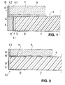
- the supporting module is a foam plastic plate 2 made of XPS foam, which is covered at least on its surface with a 0.5 to 2 mm thick, hardened and reinforced mortar layer 4.
- the foam plastic plate 2, in the Figures 1 and 2 is shown broken off, is positively connected by insertion into a cavity 5 with the edge termination profile 1.1 and 1.2. If necessary, an additional bonding within the cavity 5 can take place.
- edge termination profile 1.1 has first been made as extruded profile of a thermoplastic, such as a polycarbonate. According to the application, the corresponding lengths are cut off.
- the edge termination profile 1.1 results in the profile hollow chamber 5, which is bordered by a front wall leg 10 and two rectified, parallel and spaced boundary legs 11 and 12. The distance between the limiting legs 11 and 12 with each other depends on the thickness of the module to be supported, whereby the configuration of the FIGS. 1 and 2 can be used in a similar manner.
- the upper side of the upper boundary leg 11 forms a relatively short support surface for the edge area 6.1 of a natural stone slab 6, for example of granite.
- a natural stone slab 6 for example of granite.
- the solidified bonding and mortar layer 4 is introduced.
- an L-shaped angle section 13 is provided, in which the shorter L-leg 14 results as a linear continuation of the upper limiting leg 11, so that the longer L-leg results in a overhanging the end wall leg 10 stop area with stop web 15.
- the bonding and mortar layer 4 settles in the interior between the edge 6.2 and the longer L-leg, i. the stop bar 15, away.
- the edge termination profile 1.1 further offers the advantage that the area which is spanned by the L configuration of the first L-leg 14 and end wall leg 10, at least one facing element 9 can be installed.
- a facing element 9 may consist of a plastic strip or a series of tile elements.
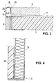
- FIG. 2 is instead of the rigid foam plastic plate 2 from a wood derivatives, here a chipboard, used.
- the edge termination profile 1.2 as in FIG. 2 is also provided with a profile hollow chamber 5, which is bordered by a front wall leg 10 and two spaced apart limbs 11 and 12.
- the one-piece edge termination profile has an edge stop, which continues linearly from the end wall leg 10 and thus becomes the stop web 15.
- the edge termination profile 1.2 is here made of a rolled stainless steel profile in a cut-to-length configuration.
- the edge 6.2 of a vanity tile 6 is covered and protected.
- the thin-bed mortar 4 does not continue into the cavity 16 between the edge end face in the stop web 15.
- FIG. 3 a modified configuration of an edge termination profile 24 is shown.
- the parts provided with the same reference numerals correspond to those of FIG. 1 ,
- a rounded flange 26 In order to bridge the gap 18 between the edge surfaces 6.2 and the inside of the stop web 15, joins the stop web 15 a rounded flange 26 at. This can be formed by molding or bending on a corresponding extension of the stop web 15.
- FIGS. 5 and 6 Edge termination profiles - reference numbers 40.1 and 40.2 - shown.
- the supporting module is a foam plastic plate 2 made of EPS foam, which is occupied at least on its surface with a 0.5 to 2 mm thick hardened and reinforced mortar layer 4. Die Schaumstoffstoffplatte 2, die in den FIGS. 5 and 6 is shown broken off, is inserted into the cavity 45 and connected to the edge termination profile 40.1 and 40.2. Within the cavity 45, the foam plastic plate 2 is glued to the edge termination profile 40.1 and 40.2.
- edge termination profile 40.1 or 40.2 has initially been produced as an extruded profile of a light metal alloy, such as duralumin. According to the application, the corresponding lengths are cut off.
- the edge termination profile 40.1 comprises the profile hollow chamber 45 which is delimited by an end wall limb 10 and the delimitation limb 41.
- the length of the end wall leg 10 depends on the thickness of the module to be supported, the configuration of the FIGS. 5 and 6 can be used in a similar manner.
- the end wall leg 10 ends with a free lower end.
- the top of the limiting leg 41 forms the support surface for a natural stone slab 6, for example of stone material.
- a consolidated thin-bed bonding and mortar layer 4 is introduced.
- an L-shaped angle part profile 13 is provided, in which the shorter L-leg 14 also results in a linear continuation of the limiting leg 41, so that the longer L-leg results in a stop area protruding over the end wall leg 10 with stop web 15.
- FIG. 6 instead of the hard foam plastic plate, a plate from a wood derivatives, here a chipboard, used.
- the edge termination profile 40.2, as in FIG. 2 is also provided with a profile hollow chamber 45 which is spanned by a front wall leg 10 and the limiting leg 41.
- the one-piece edge termination profile 40.2 has an edge stop, which continues linearly from the end wall leg 10 and thus becomes the stop web 15.
- the edge termination profile 40.2 is here made of a rolled stainless steel profile in a cut-to-length configuration.
- the edge 6.2 of a vanity tile 6 is covered and protected.
- the thin-bed mortar 4 does not continue into the cavity 16 between the edge end face in the stop web 15.
- FIG. 7 a modified configuration of an edge termination profile 44 is shown.
- the same with Reference numerals provided parts correspond to those of FIG. 1 ,
- each bonded material is roughened or patterned as required.
- the possibilities for this are known to the person skilled in the art, so that it need not be discussed further here.
- a described edge termination profile 1.2 or 40.2 can also be used for attaching wall decoration panels 30 with a deposited, self-supporting thermal insulation panel 31 as a self-supporting module.
- the edge termination profile 1.2 or 40.2 used as a carrier profile for the wall paneling.
Abstract
Description
Die Erfindung betrifft ein Kantenabschlussprofil für Küchenarbeitsplatten oder sanitäre Gegenstände, wie Waschtische und dergleichen, die mit einer Decklage aus Naturstein- oder Keramikplatten versehen sind.The invention relates to an edge termination profile for kitchen countertops or sanitary items, such as vanities and the like, which are provided with a cover layer of natural stone or ceramic plates.
Kantenabschussprofile dienen dazu, Arbeitsplatten in Küchen oder in Feuchträumen seitlich abzuschließen, wobei zum einen Beschädigungen oder Verletzungen vermieden werden sollen, zum anderen Verschmutzungen und Durchfeuchtungen nicht eindringen sollen, die sich insbesondere im Randbereich zeigen.Edge firing profiles are used to finish worktops in kitchens or in wet rooms on the side, on the one hand to avoid damage or injury, on the other dirt and moisture should not penetrate, which show up especially in the edge area.
Ein derartiges Kantenabschlussprofil ist beispielsweise aus
Für die Erfindung stellt sich die Aufgabe, ein Kantenabschlussprofil so zu gestalten, dass insbesondere bei Verwendung von Holzplatten oder Kunststoffschaumplatten bei Küchenarbeitsplatten, Waschtische und dergleichen ein einfacher und haltbarer Kantenabschluss herstellbar ist.For the invention, the task of designing an edge termination profile so that in particular when using wood panels or plastic foam panels in kitchen worktops, vanities and the like, a simple and durable edge termination can be produced.
Diese Aufgabe wird gelöst mit einem Kantenabschlussprofil der eingangs genannten Art, welches eine Profil-Hohlkammer aufweist, die von einem Stirnwandschenkel und zwei im Wesentlichen gleichgerichteten, parallelen und untereinander beabstandenden Begrenzungsschenkeln eingefasst und mit einem Plattenelement oder einer Isoliermasse auffüllbar sind, wobei die Begrenzungsschenkel mit dem Stirnwandschenkel im rechten Winkel abstehend verbunden sind und der oben liegende Begrenzungsschenkel auf seiner Oberseite eine Tragfläche für die Decklage bildet, sowie mit einem Kantenanschlag für die Decklage, der mit dem Stirnwandschenkel verbunden ist. Vorzugsweise wird der genannte Kantenanschlag mit dem Stirnwandschenkel einstückig verbunden.This object is achieved with an edge termination profile of the type mentioned, which has a profile hollow chamber, of a front wall leg and two substantially rectified, parallel and spaced apart boundary legs are edged and filled with a plate member or an insulating material, wherein the boundary legs are connected to the end wall leg projecting at right angles and the overhead boundary leg forms a support surface for the top layer on its top, and with an edge stop for the cover layer, which is connected to the end wall legs. Preferably, said edge stopper is integrally connected to the end wall leg.
Eine auf gleicher Ebene liegende Lösung ist dann gegeben, wenn eine Profilkammer, die von einem Stirnwandschenkel und einem Begrenzungsschenkel einseitig begrenzt ist, vorhanden ist, wobei der Begrenzungsschenkel mit dem Stirnwandschenkel im rechten Winkel in dessen Mittelbereich abstehend verbunden ist und der Begrenzungsschenkel auf einer Oberseite eine Tragfläche für die Decklage bildet, sowie mit einem Anschlagsteg für die Decklage, der mit dem Stirnwandschenkel verbunden ist.An in-plane solution is given when a profile chamber, which is bounded on one side by an end wall leg and a limiting leg, is present, wherein the boundary leg is connected to the end wall leg at a right angle in the central region thereof projecting and the limiting leg on a top one Forming surface for the cover layer, as well as with a stop web for the cover layer, which is connected to the end wall leg.
Es ergibt sich damit ein "zweistöckiges" Kantenabschlussprofil, bei dem eine abgedeckte Lage, bestehend aus einem Plattenelement, und eine Sichtlage, bestehend aus Naturstein- oder Keramikplatten, zusammen aufgebaut und durch das Kantenabschlussprofil seitlich sowohl abgedeckt als auch positioniert sind.This results in a "two-story" edge termination profile, in which a covered layer consisting of a plate element, and a visible layer consisting of natural stone or ceramic plates, constructed together and laterally both covered and positioned by the edge termination profile.
Als Ausführungsbeispiele für den Kantenanschlag haben sich als vorteilhaft erwiesen:
- Der Kantenanschlag ist als sich aus dem Stirnwandschenkel fortsetzender Anschlagsteg gestaltet, oder
- der Kantenabschluss setzt sich als L-förmiges Winkelteilprofil mit dem ersten L-Schenkel an den oben liegenden Begrenzungsschenkel linear fort, wobei der Stirnwandschenkel und der erste L-Schenkel eine L-Konfiguration ausbilden und der andere L-Schenkel den Stirnanschlag bildet.
- The edge stop is designed as extending from the end wall leg stop web, or
- the edge termination continues linearly as an L-shaped angle part profile with the first L-leg on the upper boundary leg, the end wall leg and the first L-leg forming an L-configuration and the other L-leg forming the end stop.
Das Kantenabschlussprofil wird vorzugsweise aus einem Metall- oder Kunststoff-Strangpressprofil abgelängt. Es ist aber auch möglich, ein Metall-Walzprofil entsprechend zu verwenden.The edge termination profile is preferably cut to length from a metal or plastic extruded profile. But it is also possible to use a metal roll profile accordingly.
Um den noch möglicherweise vorhandenen Hohlraum zu überdecken, der sich an der Kante im Bereich des Anschlags öffnet, wird der Kantenabschluss mit einem gerundeten Bördelungsprofil versehen. Das Bördelungsprofil kann auch aus einem anderen Material als das Kantenabschlussprofil im Übrigen hergestellt sein. Beispielsweise kann sich das Bördelungsprofil aus einem etwas flexiblen Kunststoff herstellen lassen, während das übrige Profil aus Metall besteht.In order to cover the possibly existing cavity, which opens at the edge in the area of the stop, the edge termination is provided with a rounded crimping profile. The curling profile can also be made of a material other than the edge finishing profile otherwise. For example, the crimping profile can be made of a somewhat flexible plastic, while the rest of the profile is made of metal.
Die Erfindung bezieht sich ferner auf einen Kantenabschluss, der unter Verwendung eines Kantenabschlussprofils nach einem der vorhergehend beschriebenen Merkmale hergestellt ist. Dabei wird in den Profil-Hohlraum formschlüssig das Kantenende einer Arbeitsplatte aus Holz, Holzderivaten oder Schaumkunststoff eingesetzt bzw. formschlüssig eingesteckt und dort gehalten, wobei zusätzlich Verklebungen oder andere Befestigungsmittel angewendet werden, die vorzugsweise von außen nicht zu erkennen sind. Die Platte kann über eine Klebstoff- oder Mörtelausgleichsschicht mit einem darauf liegenden Belag verbunden sein.The invention further relates to an edge termination made using an edge termination profile according to any of the features previously described. In this case, the edge end of a worktop made of wood, wood derivatives or foamed plastic is positively inserted and positively held inserted and held there in the profile cavity, in addition adhesions or other fastening means are used, which are preferably not visible from the outside. The plate can be over an adhesive or mortar compensation layer be associated with a coating thereon.
Schließlich sei darauf hingewiesen, dass ein Kantenabschluss auch noch zusätzlich mit einem Verblendelement bestückt sein kann, das vorzugsweise in dem Bereich, der von der L-Konfiguration aus erstem L-Schenkel und Stirnwandschenkel aufgespannt ist, angeordnet wird.Finally, it should be pointed out that an edge termination can also be additionally equipped with a veneering element, which is preferably arranged in the region which is spanned by the L configuration of the first L leg and end wall limb.
Ausführungsbeispiele der Erfindung werden in der nachfolgenden Beschreibung dargestellt. Die Figuren der Zeichnung zeigen im Einzelnen:
- Fig. 1
- den Querschnitt durch einen Kantenabschluss mit einem Kantenabschlussprofil gem. Erfindung in einer ersten Ausführungsform;
- Fig. 2
- einen Querschnitt ähnlich wie
Figur 1 , in einer zweiten Ausführungsform; - Fig. 3
- Kantenabschluss gem.
Figur 1 mit einer Bördelung im Anschlagbereich; - Fig. 4
- ein Detail einer Wandverkleidung;
- Fig. 5
- den Querschnitt durch einen Kantenabschluss mit einem Kantenabschlussprofil gemäß Erfindung in einer dritten Ausführungsform;
- Fig. 6
- einen Querschnitt ähnlich wie
Figur 1 , in einer vierten Ausführungsform; - Fig. 7
- Kantenabschluss gem.
Fig. 5 mit einer Bördelung im Anschlagbereich; - Fig. 8
- ein Detail einer Wandverkleidung.
- Fig. 1
- the cross section through an edge termination with an edge termination profile gem. Invention in a first embodiment;
- Fig. 2
- a cross section similar to
FIG. 1 in a second embodiment; - Fig. 3
- Edge termination gem.
FIG. 1 with a flange in the stop area; - Fig. 4
- a detail of a wall cladding;
- Fig. 5
- the cross section through an edge termination with an edge termination profile according to the invention in a third embodiment;
- Fig. 6
- a cross section similar to
FIG. 1 in a fourth embodiment; - Fig. 7
- Edge termination gem.
Fig. 5 with a flange in the stop area; - Fig. 8
- a detail of a wall paneling.
Es sei darauf hingewiesen, dass sich die Begriffe "oben" und "unten" auf die dargestellte Ausführungsform gem.
Unter Bezugnahme auf die
Das in
Die Oberseite des oben liegenden Begrenzungsschenkels 11 bildet eine relativ kurze Tragfläche für den Kantenbereich 6.1 einer Natursteinplatte 6, beispielsweise aus Granit. Im Zwischenbereich zwischen der Unterseite der Natursteinplatte 6 und der Oberseite des Begrenzungsschenkels 11 ist die verfestigte Verklebungs- und Mörtelschicht 4 eingebracht.The upper side of the
Als Kantenabschluss und Anschlag ist ein L-förmiges Winkelteilprofil 13 vorgesehen, bei dem sich der kürzere L-Schenkel 14 als lineare Fortsetzung des oberen Begrenzungsschenkels 11 ergibt, so dass der längere L-Schenkel einen gegenüber dem Stirnwandschenkel 10 überkragenden Anschlagbereich mit Anschlagsteg 15 ergibt. Die Verklebungs- und Mörtelschicht 4 setzt sich im Innenraum zwischen der Kante 6.2 und dem längeren L-Schenkel, d.h. dem Anschlagsteg 15, fort. Durch die Verwendung einer im ausgehärteten Zustand mit einer Restzähigkeit versehenen Mörtelschicht 4, die auch armiert sein kann, lassen sich Unterschiede in der Wärmeausdehnung und entsprechende Ausdehnungsspannungen zwischen den Teilen unschädlich machen.As edge termination and stop an L-shaped
Das Kantenabschlussprofil 1.1 bietet weiterhin den Vorteil, dass der Bereich, der von der L-Konfiguration aus erstem L-Schenkel 14 und Stirnwandschenkel 10 aufgespannt ist, wenigstens ein Verblendelement 9 eingebaut werden kann. Ein solches Verblendelement 9 kann aus einem Kunststoffstreifen oder einer Reihe von Fliesenelementen bestehen.The edge termination profile 1.1 further offers the advantage that the area which is spanned by the L configuration of the first L-
In
Das Kantenabschlussprofil 1.2 ist hier aus einem gewalzten Edelstahlprofil in abgelängter Konfiguration hergestellt. Die Kante 6.2 einer Waschtisch-Fliese 6 wird abgedeckt und geschützt. Der Dünnbett-Mörtel 4 setzt sich nicht bis in den Hohlraum 16 zwischen der Kantenstirnfläche im Anschlagssteg 15 fort.The edge termination profile 1.2 is here made of a rolled stainless steel profile in a cut-to-length configuration. The edge 6.2 of a
In der
Um die Lücke 18 zwischen den Kantenflächen 6.2 und der Innenseite des Anschlagsstegs 15 zu überbrücken, schließt sich an den Anschlagssteg 15 eine gerundete Bördelung 26 an. Diese kann durch Ausformen oder Abbiegen an einer entsprechenden Verlängerung des Anschlagsstegs 15 geformt sein.In order to bridge the
Es kann aber auch eine flexible Bördelung, beispielsweise aus PVC, durch verbundene Extrusion an den Anschlagssteg - diesen an seinen Enden überfassend - befestigt werden. Damit kann optisch und haptisch ein verbesserter Übergang vom Anschlagsteg zur Belagkante erzeugt werden.But it can also be a flexible flange, for example made of PVC, by connected extrusion to the stop web - this comprehensive at its ends - be attached. Thus, an improved transition from the stop bar to the lining edge can be generated optically and haptically.
Als weitere Ausführungsform der Erfindung sind in
Das in
Die Oberseite des Begrenzungsschenkels 41 bildet die Tragfläche für eine Natursteinplatte 6, beispielsweise aus Steinwerkstoff. Im Zwischenbereich zwischen der Unterseite der Natursteinplatte 6 und der Oberseite des Begrenzungsschenkels 41 ist eine verfestigtes Dünnbett-Verklebungs- und Mörtelschicht 4 eingebracht.The top of the limiting
Als Kantenabschluss und Anschlag ist gemäß
In
Das Kantenabschlussprofil 40.2 ist hier aus einem gewalzten Edelstahlprofil in abgelängter Konfiguration hergestellt. Die Kante 6.2 einer Waschtisch-Fliese 6 wird abgedeckt und geschützt. Der Dünnbett-Mörtel 4 setzt sich nicht bis in den Hohlraum 16 zwischen der Kantenstirnfläche im Anschlagssteg 15 fort.The edge termination profile 40.2 is here made of a rolled stainless steel profile in a cut-to-length configuration. The edge 6.2 of a
In der
An den Anschlagssteg 15 schließt sich eine gerundete Bördelung 26 an, wie sie bereits anhand der
Die Oberfläche der jeweils verbundenen Materialien wird nach Erfordernis aufgeraut oder strukturiert. Die Möglichkeiten hierzu sind dem Fachmann bekannt, so dass hierauf nicht weiter eingegangen zu werden braucht.The surface of each bonded material is roughened or patterned as required. The possibilities for this are known to the person skilled in the art, so that it need not be discussed further here.
Es sei darauf hingewiesen (vgl.
Claims (14)
Priority Applications (3)
| Application Number | Priority Date | Filing Date | Title |
|---|---|---|---|
| PL10005626T PL2340740T3 (en) | 2010-01-05 | 2010-05-31 | Worktop for kitchen or wet room |
| US12/974,455 US20110163510A1 (en) | 2010-01-05 | 2010-12-21 | Edging Seal Profile |
| RU2010153353/12A RU2010153353A (en) | 2010-01-05 | 2010-12-24 | EDGE PROFILE |
Applications Claiming Priority (1)
| Application Number | Priority Date | Filing Date | Title |
|---|---|---|---|
| DE202010000626U DE202010000626U1 (en) | 2010-01-05 | 2010-01-05 | Edge trim profile |
Publications (2)
| Publication Number | Publication Date |
|---|---|
| EP2340740A1 true EP2340740A1 (en) | 2011-07-06 |
| EP2340740B1 EP2340740B1 (en) | 2014-07-30 |
Family
ID=42105700
Family Applications (1)
| Application Number | Title | Priority Date | Filing Date |
|---|---|---|---|
| EP10005626.6A Not-in-force EP2340740B1 (en) | 2010-01-05 | 2010-05-31 | Worktop for kitchen or wet room |
Country Status (9)
| Country | Link |
|---|---|
| US (1) | US20110163510A1 (en) |
| EP (1) | EP2340740B1 (en) |
| CA (1) | CA2726721A1 (en) |
| DE (1) | DE202010000626U1 (en) |
| DK (1) | DK2340740T3 (en) |
| ES (1) | ES2522519T3 (en) |
| PL (1) | PL2340740T3 (en) |
| PT (1) | PT2340740E (en) |
| RU (1) | RU2010153353A (en) |
Cited By (1)
| Publication number | Priority date | Publication date | Assignee | Title |
|---|---|---|---|---|
| CN104790469A (en) * | 2014-01-21 | 2015-07-22 | 杜拉维特股份公司 | Sanitary device comprising a wash basin and support furniture |
Families Citing this family (12)
| Publication number | Priority date | Publication date | Assignee | Title |
|---|---|---|---|---|
| EA201100751A1 (en) * | 2008-11-13 | 2011-12-30 | Уайт Фокс Текнолоджиз Лтд. | METHOD OF SEALING MEMBRANE MODULES |
| IT201600081448A1 (en) * | 2016-08-03 | 2018-02-03 | Progress Profiles Spa | PROFILE FOR THE LAYING OF RAISED FLOORS AND RAISED FLOOR INCLUDING THIS PROFILE |
| WO2018035594A1 (en) * | 2016-08-25 | 2018-03-01 | Archi Comércio De Puxadores Ltda. | Profile for forming an article of furniture |
| US10506874B2 (en) | 2018-01-22 | 2019-12-17 | Halcon Corp. | Table apparatus and method |
| US11085193B2 (en) * | 2018-04-09 | 2021-08-10 | United Construction Products, Inc. | Peripheral restraint system for elevated flooring surface |
| CN110847306B (en) * | 2018-08-21 | 2022-09-27 | 科勒公司 | Front apron board water tank with interchangeable surface |
| US11324318B2 (en) | 2018-10-04 | 2022-05-10 | Kohler Co. | Apron front sink panel assembly |
| US11406180B2 (en) | 2019-06-04 | 2022-08-09 | Halcon Corp. | Table power module devices, systems, and methods |
| USD952808S1 (en) | 2020-01-24 | 2022-05-24 | Kohler Co. | Sink |
| US11781302B2 (en) | 2020-01-24 | 2023-10-10 | Kohler Co. | Sink having removable apron and accessory systems |
| CA3118575A1 (en) * | 2020-05-13 | 2021-11-13 | Dexx Ip Holdings, Llc | Methods of constructing floating tile-based flooring and staircase systems and components thereof |
| US11131098B1 (en) * | 2020-06-17 | 2021-09-28 | Louisiana-Pacific Corporation | Drip cap water management device and system |
Citations (9)
| Publication number | Priority date | Publication date | Assignee | Title |
|---|---|---|---|---|
| US4413570A (en) * | 1980-02-27 | 1983-11-08 | Knoll International, Inc. | Table easily assembled from standardized parts and corner clamping assembly usable therewith |
| US4873806A (en) * | 1988-11-14 | 1989-10-17 | American Glass And Metal Corporation | Flexible splice for metal frame members in a curtain wall |
| DE4019287C1 (en) * | 1990-06-16 | 1992-03-12 | Schock & Co Gmbh, 7060 Schorndorf, De | Plate shaped element for e.g. kitchen work plate - includes support plate with layer and edge profile adhered to one edge |
| US5184441A (en) * | 1991-05-14 | 1993-02-09 | Allsteel Inc. | Top cap with snap-in accent strip for wall panels |
| DE29607236U1 (en) * | 1996-04-22 | 1996-06-27 | Dreer Franz | Quick connection for plate-shaped components |
| FR2781260A1 (en) * | 1998-07-17 | 2000-01-21 | Techalu | Fixing brackets for mounting attachment onto new or worn support structure for display of goods, includes series of quick fixing clips to hook onto support structure edges |
| DE10307541A1 (en) * | 2003-02-21 | 2004-09-02 | Peter Kellner | Natural stone slab, as a kitchen working surface, has a backing of a lightweight material with reinforcement strips to give a compound slab of reduced weight |
| DE202004018996U1 (en) | 2004-12-07 | 2005-03-03 | Schlüter Systems KG | Edging strip for worktops has fixing arm which is embedded in sealant, ceramic top being fitted over this and front of strip having groove, into which ceramic strip is fitted |
| US20090249723A1 (en) * | 2006-11-28 | 2009-10-08 | Palmer/Snyder Furniture Company | Portable Panel Construction and Method for Making the Same |
Family Cites Families (25)
| Publication number | Priority date | Publication date | Assignee | Title |
|---|---|---|---|---|
| US3759005A (en) * | 1971-02-16 | 1973-09-18 | Kidde & Co Walter | Panel edge and seal structure |
| US3789567A (en) * | 1972-12-29 | 1974-02-05 | American Standard Inc | Edge seals for multiple-interfitting partitions |
| EP0198157B1 (en) * | 1985-04-16 | 1990-07-18 | Stephan Wedi | Plastic expansion joint strip, especially for the border joint of a floor construction |
| DE4205927C1 (en) * | 1992-02-26 | 1993-08-19 | August 6653 Blieskastel De Braun | |
| DE9306562U1 (en) * | 1993-04-30 | 1993-08-19 | Wedi Gmbh | Stair track |
| US5433986A (en) * | 1994-02-14 | 1995-07-18 | Moscatello; David | Combination slutter and nosing strip |
| DE19518020A1 (en) * | 1995-05-17 | 1996-11-21 | Helmut Wedi | Corner cover element with cover rail for protection of tile or carpet edges |
| DE29622325U1 (en) * | 1996-12-23 | 1997-02-06 | Wedi Helmut | Balcony construction |
| US5950370A (en) * | 1997-03-20 | 1999-09-14 | Cr/Pl, L.L.C. | Bathtub support and sealing flange |
| DE19722349C2 (en) * | 1997-05-28 | 2002-12-19 | Schlueter Systems Kg | Profile to be glued on the subsurface to complete installed ceramic plates or the like |
| US6449914B1 (en) * | 1998-04-02 | 2002-09-17 | Eugene A. Horstketter | Grout sealing apparatus for concrete panels, decks, and support beams and methods for their fabrication |
| WO2000014350A1 (en) * | 1998-09-08 | 2000-03-16 | Gerard Francis Robinson | Sealing member |
| US6419238B2 (en) * | 1999-06-07 | 2002-07-16 | Mccomb Barry Hugh | Watertight seal for inclined surfaces |
| US6591575B2 (en) * | 2000-04-25 | 2003-07-15 | Robert Benedettini | Tile edging strip |
| US6338229B1 (en) * | 2000-06-23 | 2002-01-15 | James T. Botzen | Wall strip with raised bead for plaster screeding comprising two nailing strips connected by a riser strip configuration |
| EP1199424A1 (en) * | 2000-10-12 | 2002-04-24 | Schlüter-Systems KG | Bridging device for expansion joints in walls or floors of buildings |
| US6385932B1 (en) * | 2001-01-26 | 2002-05-14 | Ugo L. Melchiori | Streamlined weep screed |
| US7111435B2 (en) * | 2002-10-23 | 2006-09-26 | Leo Flores | Tile application guides and system |
| FR2850124B1 (en) * | 2003-01-16 | 2005-04-01 | Sevylor Internat | SWIMMING POOL MARGELL, IN PARTICULAR FOR OUTDOOR SWIMMING POOL, AND METHOD FOR MANUFACTURING THE SAME |
| US6898910B2 (en) * | 2003-02-04 | 2005-05-31 | Frank Bellino, Jr. | Precast composite header joint system and a method for forming and installing the same |
| US20040163343A1 (en) * | 2003-02-20 | 2004-08-26 | Larry Crocenzi | Compound structural material cover and intermediate trim strip |
| GB0519681D0 (en) * | 2005-09-28 | 2005-11-02 | Mccomb Barry P | Seal |
| DE102006033164B4 (en) * | 2006-07-15 | 2009-01-22 | Armin Wigand | Kit for a table or worktop |
| WO2009046734A1 (en) * | 2007-10-08 | 2009-04-16 | Armin Wigand | Kit for tabletop or worktop |
| US20100325969A1 (en) * | 2009-06-25 | 2010-12-30 | Kevin Hourihan | Adaptor and method for facilitating the installation of walls around tubs, showers, and the like |
-
2010
- 2010-01-05 DE DE202010000626U patent/DE202010000626U1/en not_active Expired - Lifetime
- 2010-05-31 EP EP10005626.6A patent/EP2340740B1/en not_active Not-in-force
- 2010-05-31 PL PL10005626T patent/PL2340740T3/en unknown
- 2010-05-31 ES ES10005626.6T patent/ES2522519T3/en active Active
- 2010-05-31 PT PT100056266T patent/PT2340740E/en unknown
- 2010-05-31 DK DK10005626.6T patent/DK2340740T3/en active
- 2010-12-21 US US12/974,455 patent/US20110163510A1/en not_active Abandoned
- 2010-12-23 CA CA2726721A patent/CA2726721A1/en not_active Abandoned
- 2010-12-24 RU RU2010153353/12A patent/RU2010153353A/en not_active Application Discontinuation
Patent Citations (9)
| Publication number | Priority date | Publication date | Assignee | Title |
|---|---|---|---|---|
| US4413570A (en) * | 1980-02-27 | 1983-11-08 | Knoll International, Inc. | Table easily assembled from standardized parts and corner clamping assembly usable therewith |
| US4873806A (en) * | 1988-11-14 | 1989-10-17 | American Glass And Metal Corporation | Flexible splice for metal frame members in a curtain wall |
| DE4019287C1 (en) * | 1990-06-16 | 1992-03-12 | Schock & Co Gmbh, 7060 Schorndorf, De | Plate shaped element for e.g. kitchen work plate - includes support plate with layer and edge profile adhered to one edge |
| US5184441A (en) * | 1991-05-14 | 1993-02-09 | Allsteel Inc. | Top cap with snap-in accent strip for wall panels |
| DE29607236U1 (en) * | 1996-04-22 | 1996-06-27 | Dreer Franz | Quick connection for plate-shaped components |
| FR2781260A1 (en) * | 1998-07-17 | 2000-01-21 | Techalu | Fixing brackets for mounting attachment onto new or worn support structure for display of goods, includes series of quick fixing clips to hook onto support structure edges |
| DE10307541A1 (en) * | 2003-02-21 | 2004-09-02 | Peter Kellner | Natural stone slab, as a kitchen working surface, has a backing of a lightweight material with reinforcement strips to give a compound slab of reduced weight |
| DE202004018996U1 (en) | 2004-12-07 | 2005-03-03 | Schlüter Systems KG | Edging strip for worktops has fixing arm which is embedded in sealant, ceramic top being fitted over this and front of strip having groove, into which ceramic strip is fitted |
| US20090249723A1 (en) * | 2006-11-28 | 2009-10-08 | Palmer/Snyder Furniture Company | Portable Panel Construction and Method for Making the Same |
Cited By (2)
| Publication number | Priority date | Publication date | Assignee | Title |
|---|---|---|---|---|
| CN104790469A (en) * | 2014-01-21 | 2015-07-22 | 杜拉维特股份公司 | Sanitary device comprising a wash basin and support furniture |
| CN104790469B (en) * | 2014-01-21 | 2017-01-04 | 杜拉维特股份公司 | Including washstand and the sanitary apparatus of base furniture |
Also Published As
| Publication number | Publication date |
|---|---|
| CA2726721A1 (en) | 2011-07-05 |
| RU2010153353A (en) | 2012-06-27 |
| PL2340740T3 (en) | 2014-12-31 |
| PT2340740E (en) | 2014-10-22 |
| DK2340740T3 (en) | 2014-11-17 |
| US20110163510A1 (en) | 2011-07-07 |
| DE202010000626U1 (en) | 2010-04-15 |
| EP2340740B1 (en) | 2014-07-30 |
| ES2522519T3 (en) | 2014-11-14 |
Similar Documents
| Publication | Publication Date | Title |
|---|---|---|
| EP2340740A1 (en) | Edge profile | |
| DE3739912C2 (en) | ||
| EP1766154B1 (en) | Multi-positionable wall or ceiling panel | |
| EP1527240A1 (en) | Arrangement of parts comprising connecting elements | |
| DE102007010997A1 (en) | Joint tape for sanitary facilities | |
| WO2002044497A1 (en) | Method for fixing insulating boards and corresponding dowel | |
| EP2147778B1 (en) | Light construction board for furniture construction | |
| EP3257413B1 (en) | Decorative and/or functional part for installation in a corner or a recess, for example, of an at least partly tiled room | |
| DE202004018996U1 (en) | Edging strip for worktops has fixing arm which is embedded in sealant, ceramic top being fitted over this and front of strip having groove, into which ceramic strip is fitted | |
| EP1867796B1 (en) | Composite boards for interior work | |
| DE102006062715B4 (en) | Composite panel with edge protection and method of making same | |
| DE3729378C2 (en) | ||
| EP1582651B1 (en) | Lower finishing edge of a composite thermal lining system of a façade | |
| DE202006009790U1 (en) | Two-part reveal connecting profile for window and door posts has base profile and external profile made of flexible material supplied in rolls with fixing arm of external profile insertable between component and resilient retaining web | |
| DE102005022827B4 (en) | Edging for a wall edge of a window or door reveal to form a pocket | |
| DE2815976A1 (en) | Internal insulation plate for roofs and walls - has two diagonally staggered layers forming edge steps for connecting to adjacent plate | |
| DE102004059531A1 (en) | Thermal insulation for building wall uses insulation element attached to building wall via mortar bond with mounting elements fitting into recess at rear of insulation element securing it during adhesion process | |
| DE202006013188U1 (en) | Chipboard with exposed porous end-face has groove incorporating an impermeable capping strip | |
| DE10061477B4 (en) | Prefabricated, large-format plate-shaped component | |
| DE202015105688U1 (en) | wall construction | |
| EP1516976B1 (en) | Multilayered floor covering element with grooves for connecting profiles | |
| DE6922013U (en) | SHUTTER CASE - LONGITUDINAL PART | |
| AT11073U1 (en) | EDGE PLATE WITH EDGE PROTECTION AND METHOD FOR THE PRODUCTION THEREOF | |
| DE202005009527U1 (en) | Plastic profile for interface between upright heat insulation panel and horizontal surface | |
| DE202004015283U1 (en) | Areal, multilayered floor element comprises at least one thin, pressure and wear resistant cover plate on top of a pressure resistant carrier layer whose edge surfaces are provided with grooves |
Legal Events
| Date | Code | Title | Description |
|---|---|---|---|
| PUAI | Public reference made under article 153(3) epc to a published international application that has entered the european phase |
Free format text: ORIGINAL CODE: 0009012 |
|
| AK | Designated contracting states |
Kind code of ref document: A1 Designated state(s): AL AT BE BG CH CY CZ DE DK EE ES FI FR GB GR HR HU IE IS IT LI LT LU LV MC MK MT NL NO PL PT RO SE SI SK SM TR |
|
| AX | Request for extension of the european patent |
Extension state: BA ME RS |
|
| 17P | Request for examination filed |
Effective date: 20110826 |
|
| 17Q | First examination report despatched |
Effective date: 20121206 |
|
| GRAP | Despatch of communication of intention to grant a patent |
Free format text: ORIGINAL CODE: EPIDOSNIGR1 |
|
| INTG | Intention to grant announced |
Effective date: 20140325 |
|
| RAP1 | Party data changed (applicant data changed or rights of an application transferred) |
Owner name: WEDI, STEPHAN |
|
| RIN1 | Information on inventor provided before grant (corrected) |
Inventor name: WEDI, STEPHAN |
|
| GRAS | Grant fee paid |
Free format text: ORIGINAL CODE: EPIDOSNIGR3 |
|
| GRAA | (expected) grant |
Free format text: ORIGINAL CODE: 0009210 |
|
| AK | Designated contracting states |
Kind code of ref document: B1 Designated state(s): AL AT BE BG CH CY CZ DE DK EE ES FI FR GB GR HR HU IE IS IT LI LT LU LV MC MK MT NL NO PL PT RO SE SI SK SM TR |
|
| REG | Reference to a national code |
Ref country code: GB Ref legal event code: FG4D Free format text: NOT ENGLISH |
|
| REG | Reference to a national code |
Ref country code: CH Ref legal event code: EP |
|
| REG | Reference to a national code |
Ref country code: AT Ref legal event code: REF Ref document number: 679515 Country of ref document: AT Kind code of ref document: T Effective date: 20140815 |
|
| REG | Reference to a national code |
Ref country code: IE Ref legal event code: FG4D Free format text: LANGUAGE OF EP DOCUMENT: GERMAN |
|
| REG | Reference to a national code |
Ref country code: DE Ref legal event code: R096 Ref document number: 502010007541 Country of ref document: DE Effective date: 20140911 |
|
| REG | Reference to a national code |
Ref country code: CH Ref legal event code: NV Representative=s name: SPIERENBURG AND PARTNER AG, PATENT- UND MARKEN, CH |
|
| REG | Reference to a national code |
Ref country code: PT Ref legal event code: SC4A Free format text: AVAILABILITY OF NATIONAL TRANSLATION Effective date: 20141014 |
|
| REG | Reference to a national code |
Ref country code: SE Ref legal event code: TRGR |
|
| REG | Reference to a national code |
Ref country code: NL Ref legal event code: T3 |
|
| REG | Reference to a national code |
Ref country code: ES Ref legal event code: FG2A Ref document number: 2522519 Country of ref document: ES Kind code of ref document: T3 Effective date: 20141114 |
|
| REG | Reference to a national code |
Ref country code: DK Ref legal event code: T3 Effective date: 20141113 |
|
| REG | Reference to a national code |
Ref country code: NO Ref legal event code: T2 Effective date: 20140730 |
|
| REG | Reference to a national code |
Ref country code: LT Ref legal event code: MG4D |
|
| REG | Reference to a national code |
Ref country code: PL Ref legal event code: T3 |
|
| PG25 | Lapsed in a contracting state [announced via postgrant information from national office to epo] |
Ref country code: LT Free format text: LAPSE BECAUSE OF FAILURE TO SUBMIT A TRANSLATION OF THE DESCRIPTION OR TO PAY THE FEE WITHIN THE PRESCRIBED TIME-LIMIT Effective date: 20140730 Ref country code: BG Free format text: LAPSE BECAUSE OF FAILURE TO SUBMIT A TRANSLATION OF THE DESCRIPTION OR TO PAY THE FEE WITHIN THE PRESCRIBED TIME-LIMIT Effective date: 20141030 Ref country code: GR Free format text: LAPSE BECAUSE OF FAILURE TO SUBMIT A TRANSLATION OF THE DESCRIPTION OR TO PAY THE FEE WITHIN THE PRESCRIBED TIME-LIMIT Effective date: 20141031 |
|
| PG25 | Lapsed in a contracting state [announced via postgrant information from national office to epo] |
Ref country code: CY Free format text: LAPSE BECAUSE OF FAILURE TO SUBMIT A TRANSLATION OF THE DESCRIPTION OR TO PAY THE FEE WITHIN THE PRESCRIBED TIME-LIMIT Effective date: 20140730 Ref country code: LV Free format text: LAPSE BECAUSE OF FAILURE TO SUBMIT A TRANSLATION OF THE DESCRIPTION OR TO PAY THE FEE WITHIN THE PRESCRIBED TIME-LIMIT Effective date: 20140730 Ref country code: HR Free format text: LAPSE BECAUSE OF FAILURE TO SUBMIT A TRANSLATION OF THE DESCRIPTION OR TO PAY THE FEE WITHIN THE PRESCRIBED TIME-LIMIT Effective date: 20140730 Ref country code: IS Free format text: LAPSE BECAUSE OF FAILURE TO SUBMIT A TRANSLATION OF THE DESCRIPTION OR TO PAY THE FEE WITHIN THE PRESCRIBED TIME-LIMIT Effective date: 20141130 |
|
| REG | Reference to a national code |
Ref country code: DE Ref legal event code: R082 Ref document number: 502010007541 Country of ref document: DE Representative=s name: BISCHOF & PARTNER RECHTSANWAELTE PARTNERSCHAFT, DE Ref country code: DE Ref legal event code: R082 Ref document number: 502010007541 Country of ref document: DE Representative=s name: MEISSNER, BOLTE & PARTNER GBR, DE Ref country code: DE Ref legal event code: R082 Ref document number: 502010007541 Country of ref document: DE Representative=s name: MEISSNER BOLTE PATENTANWAELTE RECHTSANWAELTE P, DE |
|
| PG25 | Lapsed in a contracting state [announced via postgrant information from national office to epo] |
Ref country code: CZ Free format text: LAPSE BECAUSE OF FAILURE TO SUBMIT A TRANSLATION OF THE DESCRIPTION OR TO PAY THE FEE WITHIN THE PRESCRIBED TIME-LIMIT Effective date: 20140730 Ref country code: SK Free format text: LAPSE BECAUSE OF FAILURE TO SUBMIT A TRANSLATION OF THE DESCRIPTION OR TO PAY THE FEE WITHIN THE PRESCRIBED TIME-LIMIT Effective date: 20140730 Ref country code: EE Free format text: LAPSE BECAUSE OF FAILURE TO SUBMIT A TRANSLATION OF THE DESCRIPTION OR TO PAY THE FEE WITHIN THE PRESCRIBED TIME-LIMIT Effective date: 20140730 Ref country code: RO Free format text: LAPSE BECAUSE OF FAILURE TO SUBMIT A TRANSLATION OF THE DESCRIPTION OR TO PAY THE FEE WITHIN THE PRESCRIBED TIME-LIMIT Effective date: 20140730 |
|
| REG | Reference to a national code |
Ref country code: DE Ref legal event code: R097 Ref document number: 502010007541 Country of ref document: DE |
|
| PLBE | No opposition filed within time limit |
Free format text: ORIGINAL CODE: 0009261 |
|
| STAA | Information on the status of an ep patent application or granted ep patent |
Free format text: STATUS: NO OPPOSITION FILED WITHIN TIME LIMIT |
|
| 26N | No opposition filed |
Effective date: 20150504 |
|
| REG | Reference to a national code |
Ref country code: DE Country of ref document: DE Representative=s name: MEISSNER, BOLTE & PARTNER GBR, DE Ref legal event code: R082 Ref document number: 502010007541 Ref country code: DE Ref legal event code: R082 Ref document number: 502010007541 Country of ref document: DE Representative=s name: MEISSNER BOLTE PATENTANWAELTE RECHTSANWAELTE P, DE |
|
| PG25 | Lapsed in a contracting state [announced via postgrant information from national office to epo] |
Ref country code: SI Free format text: LAPSE BECAUSE OF FAILURE TO SUBMIT A TRANSLATION OF THE DESCRIPTION OR TO PAY THE FEE WITHIN THE PRESCRIBED TIME-LIMIT Effective date: 20140730 |
|
| PG25 | Lapsed in a contracting state [announced via postgrant information from national office to epo] |
Ref country code: MC Free format text: LAPSE BECAUSE OF FAILURE TO SUBMIT A TRANSLATION OF THE DESCRIPTION OR TO PAY THE FEE WITHIN THE PRESCRIBED TIME-LIMIT Effective date: 20140730 |
|
| REG | Reference to a national code |
Ref country code: IE Ref legal event code: MM4A |
|
| REG | Reference to a national code |
Ref country code: FR Ref legal event code: PLFP Year of fee payment: 7 |
|
| PG25 | Lapsed in a contracting state [announced via postgrant information from national office to epo] |
Ref country code: IE Free format text: LAPSE BECAUSE OF NON-PAYMENT OF DUE FEES Effective date: 20150531 |
|
| PG25 | Lapsed in a contracting state [announced via postgrant information from national office to epo] |
Ref country code: MT Free format text: LAPSE BECAUSE OF FAILURE TO SUBMIT A TRANSLATION OF THE DESCRIPTION OR TO PAY THE FEE WITHIN THE PRESCRIBED TIME-LIMIT Effective date: 20140730 |
|
| REG | Reference to a national code |
Ref country code: FR Ref legal event code: PLFP Year of fee payment: 8 |
|
| PG25 | Lapsed in a contracting state [announced via postgrant information from national office to epo] |
Ref country code: SM Free format text: LAPSE BECAUSE OF FAILURE TO SUBMIT A TRANSLATION OF THE DESCRIPTION OR TO PAY THE FEE WITHIN THE PRESCRIBED TIME-LIMIT Effective date: 20140730 Ref country code: HU Free format text: LAPSE BECAUSE OF FAILURE TO SUBMIT A TRANSLATION OF THE DESCRIPTION OR TO PAY THE FEE WITHIN THE PRESCRIBED TIME-LIMIT; INVALID AB INITIO Effective date: 20100531 |
|
| PGFP | Annual fee paid to national office [announced via postgrant information from national office to epo] |
Ref country code: NL Payment date: 20170516 Year of fee payment: 8 |
|
| PGFP | Annual fee paid to national office [announced via postgrant information from national office to epo] |
Ref country code: GB Payment date: 20170531 Year of fee payment: 8 Ref country code: CH Payment date: 20170529 Year of fee payment: 8 Ref country code: NO Payment date: 20170526 Year of fee payment: 8 Ref country code: DE Payment date: 20170530 Year of fee payment: 8 Ref country code: FR Payment date: 20170530 Year of fee payment: 8 Ref country code: DK Payment date: 20170531 Year of fee payment: 8 |
|
| PG25 | Lapsed in a contracting state [announced via postgrant information from national office to epo] |
Ref country code: TR Free format text: LAPSE BECAUSE OF FAILURE TO SUBMIT A TRANSLATION OF THE DESCRIPTION OR TO PAY THE FEE WITHIN THE PRESCRIBED TIME-LIMIT Effective date: 20140730 |
|
| PGFP | Annual fee paid to national office [announced via postgrant information from national office to epo] |
Ref country code: SE Payment date: 20170526 Year of fee payment: 8 Ref country code: PL Payment date: 20170529 Year of fee payment: 8 Ref country code: IT Payment date: 20170522 Year of fee payment: 8 Ref country code: ES Payment date: 20170615 Year of fee payment: 8 Ref country code: FI Payment date: 20170524 Year of fee payment: 8 Ref country code: BE Payment date: 20170524 Year of fee payment: 8 Ref country code: AT Payment date: 20170525 Year of fee payment: 8 Ref country code: LU Payment date: 20170524 Year of fee payment: 8 Ref country code: PT Payment date: 20170517 Year of fee payment: 8 |
|
| PG25 | Lapsed in a contracting state [announced via postgrant information from national office to epo] |
Ref country code: MK Free format text: LAPSE BECAUSE OF FAILURE TO SUBMIT A TRANSLATION OF THE DESCRIPTION OR TO PAY THE FEE WITHIN THE PRESCRIBED TIME-LIMIT Effective date: 20140730 |
|
| PG25 | Lapsed in a contracting state [announced via postgrant information from national office to epo] |
Ref country code: AL Free format text: LAPSE BECAUSE OF FAILURE TO SUBMIT A TRANSLATION OF THE DESCRIPTION OR TO PAY THE FEE WITHIN THE PRESCRIBED TIME-LIMIT Effective date: 20140730 |
|
| REG | Reference to a national code |
Ref country code: DE Ref legal event code: R119 Ref document number: 502010007541 Country of ref document: DE |
|
| REG | Reference to a national code |
Ref country code: CH Ref legal event code: PL |
|
| REG | Reference to a national code |
Ref country code: NO Ref legal event code: MMEP |
|
| REG | Reference to a national code |
Ref country code: DK Ref legal event code: EBP Effective date: 20180531 Ref country code: NL Ref legal event code: MM Effective date: 20180601 |
|
| REG | Reference to a national code |
Ref country code: AT Ref legal event code: MM01 Ref document number: 679515 Country of ref document: AT Kind code of ref document: T Effective date: 20180531 |
|
| REG | Reference to a national code |
Ref country code: SE Ref legal event code: EUG |
|
| GBPC | Gb: european patent ceased through non-payment of renewal fee |
Effective date: 20180531 |
|
| REG | Reference to a national code |
Ref country code: BE Ref legal event code: MM Effective date: 20180531 |
|
| PG25 | Lapsed in a contracting state [announced via postgrant information from national office to epo] |
Ref country code: SE Free format text: LAPSE BECAUSE OF NON-PAYMENT OF DUE FEES Effective date: 20180601 Ref country code: FI Free format text: LAPSE BECAUSE OF NON-PAYMENT OF DUE FEES Effective date: 20180531 Ref country code: AT Free format text: LAPSE BECAUSE OF NON-PAYMENT OF DUE FEES Effective date: 20180531 Ref country code: NO Free format text: LAPSE BECAUSE OF NON-PAYMENT OF DUE FEES Effective date: 20180531 Ref country code: PT Free format text: LAPSE BECAUSE OF NON-PAYMENT OF DUE FEES Effective date: 20181130 |
|
| PG25 | Lapsed in a contracting state [announced via postgrant information from national office to epo] |
Ref country code: LI Free format text: LAPSE BECAUSE OF NON-PAYMENT OF DUE FEES Effective date: 20180531 Ref country code: CH Free format text: LAPSE BECAUSE OF NON-PAYMENT OF DUE FEES Effective date: 20180531 |
|
| PG25 | Lapsed in a contracting state [announced via postgrant information from national office to epo] |
Ref country code: LU Free format text: LAPSE BECAUSE OF NON-PAYMENT OF DUE FEES Effective date: 20180531 |
|
| PG25 | Lapsed in a contracting state [announced via postgrant information from national office to epo] |
Ref country code: GB Free format text: LAPSE BECAUSE OF NON-PAYMENT OF DUE FEES Effective date: 20180531 Ref country code: FR Free format text: LAPSE BECAUSE OF NON-PAYMENT OF DUE FEES Effective date: 20180531 Ref country code: DE Free format text: LAPSE BECAUSE OF NON-PAYMENT OF DUE FEES Effective date: 20181201 Ref country code: IT Free format text: LAPSE BECAUSE OF NON-PAYMENT OF DUE FEES Effective date: 20180531 Ref country code: NL Free format text: LAPSE BECAUSE OF NON-PAYMENT OF DUE FEES Effective date: 20180601 |
|
| PG25 | Lapsed in a contracting state [announced via postgrant information from national office to epo] |
Ref country code: BE Free format text: LAPSE BECAUSE OF NON-PAYMENT OF DUE FEES Effective date: 20180531 Ref country code: DK Free format text: LAPSE BECAUSE OF NON-PAYMENT OF DUE FEES Effective date: 20180531 |
|
| REG | Reference to a national code |
Ref country code: ES Ref legal event code: FD2A Effective date: 20190913 |
|
| PG25 | Lapsed in a contracting state [announced via postgrant information from national office to epo] |
Ref country code: ES Free format text: LAPSE BECAUSE OF NON-PAYMENT OF DUE FEES Effective date: 20180601 |
|
| PG25 | Lapsed in a contracting state [announced via postgrant information from national office to epo] |
Ref country code: PL Free format text: LAPSE BECAUSE OF NON-PAYMENT OF DUE FEES Effective date: 20180531 |