EP2348603A2 - Wireless power transmission device and method - Google Patents
Wireless power transmission device and method Download PDFInfo
- Publication number
- EP2348603A2 EP2348603A2 EP10190763A EP10190763A EP2348603A2 EP 2348603 A2 EP2348603 A2 EP 2348603A2 EP 10190763 A EP10190763 A EP 10190763A EP 10190763 A EP10190763 A EP 10190763A EP 2348603 A2 EP2348603 A2 EP 2348603A2
- Authority
- EP
- European Patent Office
- Prior art keywords
- terminal
- wireless power
- power transmission
- information
- transmission device
- Prior art date
- Legal status (The legal status is an assumption and is not a legal conclusion. Google has not performed a legal analysis and makes no representation as to the accuracy of the status listed.)
- Granted
Links
- 230000005540 biological transmission Effects 0.000 title claims abstract description 178
- 238000000034 method Methods 0.000 title claims abstract description 31
- 238000010586 diagram Methods 0.000 description 6
- 238000005516 engineering process Methods 0.000 description 2
- 238000012986 modification Methods 0.000 description 2
- 230000004048 modification Effects 0.000 description 2
- 230000001413 cellular effect Effects 0.000 description 1
- 238000010276 construction Methods 0.000 description 1
- 238000011161 development Methods 0.000 description 1
- 230000003287 optical effect Effects 0.000 description 1
- 238000012545 processing Methods 0.000 description 1
- 238000012546 transfer Methods 0.000 description 1
Images


Classifications
-
- H—ELECTRICITY
- H02—GENERATION; CONVERSION OR DISTRIBUTION OF ELECTRIC POWER
- H02J—CIRCUIT ARRANGEMENTS OR SYSTEMS FOR SUPPLYING OR DISTRIBUTING ELECTRIC POWER; SYSTEMS FOR STORING ELECTRIC ENERGY
- H02J7/00—Circuit arrangements for charging or depolarising batteries or for supplying loads from batteries
- H02J7/00047—Circuit arrangements for charging or depolarising batteries or for supplying loads from batteries with provisions for charging different types of batteries
-
- H—ELECTRICITY
- H02—GENERATION; CONVERSION OR DISTRIBUTION OF ELECTRIC POWER
- H02J—CIRCUIT ARRANGEMENTS OR SYSTEMS FOR SUPPLYING OR DISTRIBUTING ELECTRIC POWER; SYSTEMS FOR STORING ELECTRIC ENERGY
- H02J50/00—Circuit arrangements or systems for wireless supply or distribution of electric power
- H02J50/20—Circuit arrangements or systems for wireless supply or distribution of electric power using microwaves or radio frequency waves
-
- H—ELECTRICITY
- H02—GENERATION; CONVERSION OR DISTRIBUTION OF ELECTRIC POWER
- H02J—CIRCUIT ARRANGEMENTS OR SYSTEMS FOR SUPPLYING OR DISTRIBUTING ELECTRIC POWER; SYSTEMS FOR STORING ELECTRIC ENERGY
- H02J50/00—Circuit arrangements or systems for wireless supply or distribution of electric power
- H02J50/40—Circuit arrangements or systems for wireless supply or distribution of electric power using two or more transmitting or receiving devices
-
- H—ELECTRICITY
- H02—GENERATION; CONVERSION OR DISTRIBUTION OF ELECTRIC POWER
- H02J—CIRCUIT ARRANGEMENTS OR SYSTEMS FOR SUPPLYING OR DISTRIBUTING ELECTRIC POWER; SYSTEMS FOR STORING ELECTRIC ENERGY
- H02J50/00—Circuit arrangements or systems for wireless supply or distribution of electric power
- H02J50/80—Circuit arrangements or systems for wireless supply or distribution of electric power involving the exchange of data, concerning supply or distribution of electric power, between transmitting devices and receiving devices
-
- H—ELECTRICITY
- H02—GENERATION; CONVERSION OR DISTRIBUTION OF ELECTRIC POWER
- H02J—CIRCUIT ARRANGEMENTS OR SYSTEMS FOR SUPPLYING OR DISTRIBUTING ELECTRIC POWER; SYSTEMS FOR STORING ELECTRIC ENERGY
- H02J7/00—Circuit arrangements for charging or depolarising batteries or for supplying loads from batteries
- H02J7/00032—Circuit arrangements for charging or depolarising batteries or for supplying loads from batteries characterised by data exchange
- H02J7/00036—Charger exchanging data with battery
-
- H04B5/79—
-
- H—ELECTRICITY
- H02—GENERATION; CONVERSION OR DISTRIBUTION OF ELECTRIC POWER
- H02J—CIRCUIT ARRANGEMENTS OR SYSTEMS FOR SUPPLYING OR DISTRIBUTING ELECTRIC POWER; SYSTEMS FOR STORING ELECTRIC ENERGY
- H02J2310/00—The network for supplying or distributing electric power characterised by its spatial reach or by the load
- H02J2310/10—The network having a local or delimited stationary reach
- H02J2310/20—The network being internal to a load
- H02J2310/22—The load being a portable electronic device
Definitions
- the following description relates to a wireless power transmission device and method, and more particularly, to a wireless power transmission device and method for transmitting and receiving information without any additional information transmission device.
- Portable electronic products As well as household appliances, can function to wirelessly transmit data, but can only receive power provided through power lines.
- wireless power transmission technologies for supplying power in a wireless manner have been studied in recent years.
- Wireless energy transfer or wireless power occurs where electrical energy is transmitted from a power source to an electrical load without interconnecting wires.
- a distance between a wireless power transmission device and a terminal is highly likely to vary over time, and requirements to match a resonator of the wireless power transmission device with a resonator of the terminal may also be changed.
- a wireless power transmission device including: a transmitter configured to wirelessly transmit power to a terminal, and a controller configured to control an amount of power transmitted wirelessly by the transmitter, based on transmission information transmitted to the terminal.
- the controller may include a switch, the switch configured to cut off or supply the power transmitted wirelessly to the terminal, depending on the transmission information.
- the controller may be further configured to control a transmission frequency, based on the transmission information.
- the controller may include a phase locked loop (PLL) circuit configured to control the transmission frequency.
- PLL phase locked loop
- the controller may be further configured to control an internal impedance, based on the transmission information.
- the wireless power transmission device may further include: a measuring unit configured to measure a reflected wave of a transmission signal transmitted to the terminal, and an analyzer configured to analyze, based on the measured reflected wave, terminal information received from the terminal.
- the measuring unit may include a directional coupler configured to measure the reflected wave.
- a terminal including: a receiver configured to wirelessly receive power from a wireless power transmission device, and a controller configured to control an internal impedance based on terminal information transmitted to the wireless power transmission device.
- the controller may include: a first load, a second load, and a switch connected to one of: the first load and the second load, depending on the terminal information.
- the terminal may further include: a measuring unit configured to measure an amount of power received wirelessly from the wireless power transmission device, and an analyzer configured to analyze, based on the measured amount of power, transmission information received from the wireless power transmission device.
- a wireless power transmission method including: wirelessly transmitting power to a terminal, and controlling an amount of power transmitted wirelessly to the terminal, based on transmission information transmitted to the terminal.
- the wireless power transmission method may further include: measuring a reflected wave of a transmission signal transmitted to the terminal, and analyzing, based on the measured reflected wave, terminal information received from the terminal.
- the wireless power transmission method may further include measuring the reflected wave with a directional coupler.
- the wireless power transmission method may further include cutting off or supplying the power transmitted wirelessly to the terminal, depending on the transmission information.
- the wireless power transmission method may further include controlling a transmission frequency, based on the transmission information.
- the wireless power transmission method may further include controlling an internal impedance, based on the transmission information.
- a wireless power transmission method including: wirelessly receiving power from a wireless power transmission device, and controlling an internal impedance based on terminal information transmitted to the wireless power transmission device.
- the wireless power transmission method may further include connecting a switch to one of: a first load and a second load, depending on the terminal information.
- the wireless power transmission method may further include: measuring an amount of power received wirelessly from the wireless power transmission device, and analyzing, based on the measured amount of power, transmission information received from the wireless power transmission device.
- FIG. 1 illustrates a configuration of a wireless power transmission device 100.
- the wireless power transmission device 100 may include a transmitter 101 and a controller 102.
- the wireless power transmission device 100 may further include a power source 104.
- the wireless power transmission device 100 may be any device capable of wirelessly transmitting power to a terminal 110. Additionally, the wireless power transmission device 100 may be inserted as a module into the terminal 110.
- the terminal 110 may be any device capable of being operated by power, e.g., a television (TV), a mobile phone, a game console, a refrigerator, or other devices.
- the transmitter 101 may wirelessly transmit power to the terminal 110.
- the controller 102 may control an amount of the power transmitted wirelessly by the transmitter 101, based on transmission information 103 transmitted to the terminal 110.
- the wireless power transmission device 100 may transmit the transmission information 103 to the terminal 110 by controlling the amount of the power, rather than by using an additional device for transmission of the transmission information 103.
- the controller 102 may control the amount of the power to be reduced, or in response to the transmission information being "1", the controller 102 may control the amount of the power to be increased. It should be appreciated that the use of "0" and "1" is for example purposes only, and the specific numbers may be reversed or otherwise changed.
- the “transmission information 103" refers to information to be transmitted by the wireless power transmission device 100 to the terminal 110.
- the transmission information 103 may include information regarding the wireless power transmission device 100, for example, an identification (ID) and a type for the wireless power transmission device 100, information regarding a transmission range which may enable the wireless power transmission device 100 to wirelessly transmit power, and information regarding whether the wireless power transmission device 100 is successfully matched with the terminal 110 when wirelessly transmitting the power.
- ID identification
- the transmission information 103 may include various types of information which the wireless power transmission device 100 desires to transmit to the terminal 110, regardless of contents of the information to be transmitted.
- the transmission information 103 may be binary scale data, although embodiments are not limited thereto.
- the wireless power transmission device 100 may further include an input unit 105 to receive the transmission information 103.
- the controller 102 may control a transmission frequency based on the transmission information 103.
- the controller 102 may also control the amount of the power transmitted to the terminal 110, by controlling the transmission frequency.
- the controller 102 may include a phase locked loop (PLL) circuit, to control the transmission frequency using the PLL circuit.
- PLL phase locked loop
- the controller 102 may control an internal impedance of the wireless power transmission device 100 based on the transmission information 103.
- the controller 102 may also control the amount of the power transmitted to the terminal 110, by controlling the internal impedance.
- FIG. 2 illustrates a configuration of a wireless power transmission device 200.
- a controller 210 of the wireless power transmission device 200 may include a switch 220.
- the switch 220 may cut off or supply power (e.g., from the power source 104 of FIG. 1 ) which may be transmitted by the wireless power transmission device 200 wirelessly to a terminal, depending on transmission information 230.
- the switch 220 in response to the transmission information 230 being "0", the switch 220 may be opened to cut off the wirelessly transmitted power, or alternatively in response to the transmission information 230 being "1", the switch 220 may be closed to supply the wirelessly transmitted power.
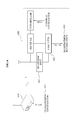
- FIG. 3 illustrates a configuration of a wireless power transmission device 300.
- the wireless power transmission device 300 may include a measuring unit 301 and an analyzer 302.
- the wireless power transmission device 300 may further include a power source (e.g., power source 104), a controller (e.g., controller 102 or 200), and a transmitter (e.g., transmitter 101).
- a power source e.g., power source 104
- a controller e.g., controller 102 or 200
- a transmitter e.g., transmitter 101
- the wireless power transmission device 300 may send a transmission signal 320 to a terminal 310, in order to wirelessly transmit power to the terminal 310.
- a part of the transmission signal 320 may be reflected and returned, which is referred to as a "reflected wave 330.”
- the measuring unit 301 may measure the reflected wave 330 of the transmission signal 320 transmitted to the terminal 310.
- the measuring unit 301 may include a directional coupler 304, to measure the reflected wave 330 using the directional coupler.
- the analyzer 302 may analyze terminal information 311 received from the terminal 310.
- the terminal 310 may transmit the terminal information 311 to the wireless power transmission device 300.
- An example of a terminal for transmitting terminal information will be further described with reference to FIG. 4 .
- FIG. 4 illustrates a configuration of a terminal 400.
- the terminal 400 may include a receiver 401 and a controller 402.
- the receiver 401 may wirelessly receive power from a wireless power transmission device 410.
- the controller 402 may control an internal impedance of the terminal 400, based on terminal information 403 transmitted to the wireless power transmission device 410.
- the terminal 400 may send the terminal information 403 to the wireless power transmission device 410 by controlling the internal impedance and controlling a reflected wave 430 of a transmission signal 420 received from the wireless power transmission device 410, rather than by using an additional device for transmission of the terminal information 403.
- the controller 402 may control the internal impedance such that a power of the reflected wave 430 may be reduced.
- the controller 402 may control the internal impedance such that the power of the reflected wave 430 may be increased.
- the controller 402 may control the internal impedance such that an amplitude of the reflected wave 430 may increase or decrease, depending on the terminal information 403.
- the terminal information 403 refers to information to be transmitted by the terminal 400 to the wireless power transmission device 410.
- the terminal information 403 may include information regarding whether the terminal 400 may currently require power, information regarding an amount of power that may be required by the terminal 400 in response to the terminal 400 may require the power, information regarding whether the terminal 400 is sufficiently matched with the wireless power transmission device 410 when wirelessly receiving the power, and information regarding a charging rate of the terminal 400.
- the terminal information 403 may include various types of information which the terminal 400 desires to transmit to the wireless power transmission device 410, regardless of contents of the information to be transmitted by the terminal 400.
- the terminal information 403 may be binary scale data, although embodiments are not limited thereto.
- the terminal 400 may further include an input unit (e.g., input unit 105 of FIG. 1 ) to receive the terminal information 403.
- an input unit e.g., input unit 105 of FIG. 1
- the analyzer 302 may analyze the received terminal information 311, based on information on at least one of a variation in power and amplitude of the reflected wave 330 measured by the measuring unit 301.
- the wireless power transmission device 300 may further include an output unit 305 to output the terminal information 303 analyzed by the analyzer 302.
- FIG. 5 illustrates a configuration of a terminal 500.
- a controller 510 of the terminal 500 may include a first load 520, a second load 530, and a switch 540.
- the switch 540 may be connected to either the first load 520 or the second load 530, depending on terminal information 550. In one example, in response to the terminal information 550 being "0", the switch 540 may be connected to the first load 520, and in response to the terminal information 550 being "1", the switch 540 may be connected to the second load 530.
- FIG. 6 illustrates a configuration of a terminal 600.
- the terminal 600 may include a measuring unit 601 and an analyzer 602.
- the measuring unit 601 may measure an amount of power received wirelessly from a wireless power transmission device 610.
- the analyzer 602 may analyze transmission information 611 received from the wireless power transmission device 610. For example, the analyzer 602 may analyze the transmission information 611 1 based on a variation in the measured amount of power.
- the terminal 600 may further include an output unit (e.g., output unit 305 of FIG. 3 ) to output transmission information 603 analyzed by the analyzer 602.
- FIG. 7 illustrates a wireless power transmission method
- power may be wirelessly transmitted to a terminal in operation 710.
- An amount of power transmitted wirelessly to the terminal may be controlled based on transmission information transmitted to the terminal in operation 720.
- the amount of power may be controlled by controlling internal impedance and controlling a reflected wave of a transmission signal received from a wireless power transmission device, rather than an additional device for transmission of the transmission information being used, such that the transmission information may be transmitted to the terminal. For example, in response to the transmission information being "0", the amount of power may be controlled to be reduced, or in response to the transmission information being "1", the amount of power may be controlled to be increased.
- the wireless power transmission method of FIG. 7 may further include receiving the transmission information before operation 720.
- a transmission frequency may be controlled based on the transmission information; accordingly, the amount of power may also be controlled. Additionally, the transmission frequency may be controlled using a PLL circuit.
- an internal impedance may be controlled based on the transmission information; accordingly, the amount of power may also be controlled.
- a reflected wave of a transmission signal transmitted to the terminal may be measured.
- a directional coupler may be used to measure the reflected wave.
- terminal information received from the terminal may be analyzed based on the reflected wave as measured.
- the terminal information may be analyzed based on information on at least one of a variation in power and amplitude of the reflected wave.
- the wireless power transmission method of FIG. 7 may further include outputting the analyzed terminal information.
- the method of the example described in FIG. 7 may use any of the above-described devices for its operation or any devices consistent with the operation described herein.
- the devices e.g., the wireless power transmission device 100 or the terminal 110, described herein may refer to mobile devices such as a cellular phone, a personal digital assistant (PDA), a digital camera, a portable game console, and an MP3 player, a portable/personal multimedia player (PMP), a handheld e-book, a portable tablet and/or laptop PC, a global positioning system (GPS) navigation, and devices such as a desktop PC, a high definition television (HDTV), an optical disc player, a setup and/or set top box, and the like consistent with that disclosed herein.
- mobile devices such as a cellular phone, a personal digital assistant (PDA), a digital camera, a portable game console, and an MP3 player, a portable/personal multimedia player (PMP), a handheld e-book, a portable tablet and/or laptop PC, a global positioning system (GPS) navigation, and devices such as a desktop PC, a high definition television (HDTV), an optical disc player, a setup and/or set top box
Abstract
Description
- The following description relates to a wireless power transmission device and method, and more particularly, to a wireless power transmission device and method for transmitting and receiving information without any additional information transmission device.
- Recently, a variety of portable electronic products have been released and have become widespread, along with development of information technologies (IT). When considering characteristics of portable electronic products, battery performance of these portable electronic products is emerging as an important issue. Portable electronic products, as well as household appliances, can function to wirelessly transmit data, but can only receive power provided through power lines.
- Additionally, wireless power transmission technologies for supplying power in a wireless manner have been studied in recent years. Wireless energy transfer or wireless power occurs where electrical energy is transmitted from a power source to an electrical load without interconnecting wires. However, when considering characteristics of wireless configuration, a distance between a wireless power transmission device and a terminal is highly likely to vary over time, and requirements to match a resonator of the wireless power transmission device with a resonator of the terminal may also be changed.
- To efficiently transmit power in a wireless manner, information for power transmission is required to be exchanged between the wireless power transmission device and the terminal. Therefore, there is a need for a new method to exchange information, to improve a wireless transmission efficiency.
- In one general aspect, there is provided a A wireless power transmission device, including: a transmitter configured to wirelessly transmit power to a terminal, and a controller configured to control an amount of power transmitted wirelessly by the transmitter, based on transmission information transmitted to the terminal.
- In the wireless power transmission device, the controller may include a switch, the switch configured to cut off or supply the power transmitted wirelessly to the terminal, depending on the transmission information.
- In the wireless power transmission device, the controller may be further configured to control a transmission frequency, based on the transmission information.
- In the wireless power transmission device, the controller may include a phase locked loop (PLL) circuit configured to control the transmission frequency.
- In the wireless power transmission device, the controller may be further configured to control an internal impedance, based on the transmission information.
- The wireless power transmission device may further include: a measuring unit configured to measure a reflected wave of a transmission signal transmitted to the terminal, and an analyzer configured to analyze, based on the measured reflected wave, terminal information received from the terminal.
- In the wireless power transmission device, the measuring unit may include a directional coupler configured to measure the reflected wave.
- In another general aspect, there is provided a terminal, including: a receiver configured to wirelessly receive power from a wireless power transmission device, and a controller configured to control an internal impedance based on terminal information transmitted to the wireless power transmission device.
- In the terminal, the controller may include: a first load, a second load, and a switch connected to one of: the first load and the second load, depending on the terminal information.
- The terminal may further include: a measuring unit configured to measure an amount of power received wirelessly from the wireless power transmission device, and an analyzer configured to analyze, based on the measured amount of power, transmission information received from the wireless power transmission device.
- In another general aspect, there is provided a wireless power transmission method, including: wirelessly transmitting power to a terminal, and controlling an amount of power transmitted wirelessly to the terminal, based on transmission information transmitted to the terminal.
- The wireless power transmission method may further include: measuring a reflected wave of a transmission signal transmitted to the terminal, and analyzing, based on the measured reflected wave, terminal information received from the terminal.
- The wireless power transmission method may further include measuring the reflected wave with a directional coupler.
- The wireless power transmission method may further include cutting off or supplying the power transmitted wirelessly to the terminal, depending on the transmission information.
- The wireless power transmission method may further include controlling a transmission frequency, based on the transmission information.
- The wireless power transmission method may further include controlling an internal impedance, based on the transmission information.
- In another general aspect, there is provided a wireless power transmission method, including: wirelessly receiving power from a wireless power transmission device, and controlling an internal impedance based on terminal information transmitted to the wireless power transmission device.
- The wireless power transmission method may further include connecting a switch to one of: a first load and a second load, depending on the terminal information.
- The wireless power transmission method may further include: measuring an amount of power received wirelessly from the wireless power transmission device, and analyzing, based on the measured amount of power, transmission information received from the wireless power transmission device.
- Other features and aspects may be apparent from the following detailed description, the drawings, and the claims.
-
-
FIG. 1 is a diagram illustrating a configuration of an example wireless power transmission device. -
FIG. 2 is a diagram illustrating a configuration of another example wireless power transmission device. -
FIG. 3 is a diagram illustrating a configuration of still another example wireless power transmission device. -
FIG. 4 is a diagram illustrating a configuration of an example terminal. -
FIG. 5 is a diagram illustrating a configuration of another example terminal. -
FIG. 6 is a diagram illustrating a configuration of still another example terminal. -
FIG. 7 is a flowchart illustrating an example wireless power transmission method. - Throughout the drawings and the detailed description, unless otherwise described, the same drawing reference numerals will be understood to refer to the same elements, features, and structures. The relative size and depiction of these elements may be exaggerated for clarity, illustration, and convenience.
- The following detailed description is provided to assist the reader in gaining a comprehensive understanding of the methods, apparatuses, and/or systems described herein. Accordingly, various changes, modifications, and equivalents of the systems, apparatuses, and/or methods described herein will be suggested to those of ordinary skill in the art. The progression of processing steps and/or operations described is an example; however, the sequence of steps and/or operations is not limited to that set forth herein and may be changed as is known in the art, with the exception of steps and/or operations necessarily occurring in a certain order. It should be appreciated that the use of binary "0" and "1" may be reversed, as appropriate. Also, description of well-known functions and constructions may be omitted for increased clarity and conciseness.
-
FIG. 1 illustrates a configuration of a wirelesspower transmission device 100. - Referring to
FIG. 1 , the wirelesspower transmission device 100 may include atransmitter 101 and acontroller 102. The wirelesspower transmission device 100 may further include apower source 104. - The wireless
power transmission device 100 may be any device capable of wirelessly transmitting power to aterminal 110. Additionally, the wirelesspower transmission device 100 may be inserted as a module into theterminal 110. - The
terminal 110 may be any device capable of being operated by power, e.g., a television (TV), a mobile phone, a game console, a refrigerator, or other devices. - The
transmitter 101 may wirelessly transmit power to theterminal 110. - The
controller 102 may control an amount of the power transmitted wirelessly by thetransmitter 101, based ontransmission information 103 transmitted to theterminal 110. For example, the wirelesspower transmission device 100 may transmit thetransmission information 103 to theterminal 110 by controlling the amount of the power, rather than by using an additional device for transmission of thetransmission information 103. For example, in response to thetransmission information 103 being "0", thecontroller 102 may control the amount of the power to be reduced, or in response to the transmission information being "1", thecontroller 102 may control the amount of the power to be increased. It should be appreciated that the use of "0" and "1" is for example purposes only, and the specific numbers may be reversed or otherwise changed. - The "
transmission information 103" refers to information to be transmitted by the wirelesspower transmission device 100 to theterminal 110. Thetransmission information 103 may include information regarding the wirelesspower transmission device 100, for example, an identification (ID) and a type for the wirelesspower transmission device 100, information regarding a transmission range which may enable the wirelesspower transmission device 100 to wirelessly transmit power, and information regarding whether the wirelesspower transmission device 100 is successfully matched with theterminal 110 when wirelessly transmitting the power. However, there may be no limitation to information required or desired for the wirelesspower transmission device 100 to transmit the power wirelessly to theterminal 110; accordingly, thetransmission information 103 may include various types of information which the wirelesspower transmission device 100 desires to transmit to theterminal 110, regardless of contents of the information to be transmitted. Depending on embodiments, thetransmission information 103 may be binary scale data, although embodiments are not limited thereto. - According to an aspect, the wireless
power transmission device 100 may further include an input unit 105 to receive thetransmission information 103. - The
controller 102 may control a transmission frequency based on thetransmission information 103. Thecontroller 102 may also control the amount of the power transmitted to the terminal 110, by controlling the transmission frequency. Additionally, thecontroller 102 may include a phase locked loop (PLL) circuit, to control the transmission frequency using the PLL circuit. - In addition, the
controller 102 may control an internal impedance of the wirelesspower transmission device 100 based on thetransmission information 103. Thecontroller 102 may also control the amount of the power transmitted to the terminal 110, by controlling the internal impedance. -
FIG. 2 illustrates a configuration of a wirelesspower transmission device 200. - Referring to
FIG. 2 , acontroller 210 of the wirelesspower transmission device 200 may include aswitch 220. - The
switch 220 may cut off or supply power (e.g., from thepower source 104 ofFIG. 1 ) which may be transmitted by the wirelesspower transmission device 200 wirelessly to a terminal, depending ontransmission information 230. Depending on embodiments, in response to thetransmission information 230 being "0", theswitch 220 may be opened to cut off the wirelessly transmitted power, or alternatively in response to thetransmission information 230 being "1", theswitch 220 may be closed to supply the wirelessly transmitted power. -
FIG. 3 illustrates a configuration of a wirelesspower transmission device 300. - Referring to
FIG. 3 , the wirelesspower transmission device 300 may include a measuringunit 301 and ananalyzer 302. The wirelesspower transmission device 300 may further include a power source (e.g., power source 104), a controller (e.g.,controller 102 or 200), and a transmitter (e.g., transmitter 101). - The wireless
power transmission device 300 may send atransmission signal 320 to a terminal 310, in order to wirelessly transmit power to the terminal 310. In one example, a part of thetransmission signal 320 may be reflected and returned, which is referred to as a "reflectedwave 330." - The measuring
unit 301 may measure the reflectedwave 330 of thetransmission signal 320 transmitted to the terminal 310. Depending on embodiments, the measuringunit 301 may include adirectional coupler 304, to measure the reflectedwave 330 using the directional coupler. - Based on the reflected
wave 330 measured by the measuringunit 301, theanalyzer 302 may analyzeterminal information 311 received from the terminal 310. - The terminal 310 may transmit the
terminal information 311 to the wirelesspower transmission device 300. An example of a terminal for transmitting terminal information will be further described with reference toFIG. 4 . -
FIG. 4 illustrates a configuration of a terminal 400. - Referring to
FIG. 4 , the terminal 400 may include areceiver 401 and acontroller 402. Thereceiver 401 may wirelessly receive power from a wirelesspower transmission device 410. - The
controller 402 may control an internal impedance of the terminal 400, based onterminal information 403 transmitted to the wirelesspower transmission device 410. For example, the terminal 400 may send theterminal information 403 to the wirelesspower transmission device 410 by controlling the internal impedance and controlling a reflectedwave 430 of atransmission signal 420 received from the wirelesspower transmission device 410, rather than by using an additional device for transmission of theterminal information 403. For example, in response to theterminal information 403 being "0", thecontroller 402 may control the internal impedance such that a power of the reflectedwave 430 may be reduced. Alternatively, in response to theterminal information 403 being "1", thecontroller 402 may control the internal impedance such that the power of the reflectedwave 430 may be increased. Additionally, thecontroller 402 may control the internal impedance such that an amplitude of the reflectedwave 430 may increase or decrease, depending on theterminal information 403. - The "
terminal information 403" refers to information to be transmitted by the terminal 400 to the wirelesspower transmission device 410. Theterminal information 403 may include information regarding whether the terminal 400 may currently require power, information regarding an amount of power that may be required by the terminal 400 in response to the terminal 400 may require the power, information regarding whether the terminal 400 is sufficiently matched with the wirelesspower transmission device 410 when wirelessly receiving the power, and information regarding a charging rate of the terminal 400. However, there may be no limitation to information that may be desired for the terminal 400 to receive power wirelessly from the wirelesspower transmission device 410; accordingly, theterminal information 403 may include various types of information which the terminal 400 desires to transmit to the wirelesspower transmission device 410, regardless of contents of the information to be transmitted by theterminal 400. Depending on embodiments, theterminal information 403 may be binary scale data, although embodiments are not limited thereto. - According to an aspect, the terminal 400 may further include an input unit (e.g., input unit 105 of
FIG. 1 ) to receive theterminal information 403. - Referring back to
FIG. 3 , theanalyzer 302 may analyze the receivedterminal information 311, based on information on at least one of a variation in power and amplitude of the reflectedwave 330 measured by the measuringunit 301. Depending on embodiments, the wirelesspower transmission device 300 may further include anoutput unit 305 to output theterminal information 303 analyzed by theanalyzer 302. -
FIG. 5 illustrates a configuration of a terminal 500. - Referring to
FIG. 5 , acontroller 510 of the terminal 500 may include afirst load 520, asecond load 530, and aswitch 540. - The
switch 540 may be connected to either thefirst load 520 or thesecond load 530, depending onterminal information 550. In one example, in response to theterminal information 550 being "0", theswitch 540 may be connected to thefirst load 520, and in response to theterminal information 550 being "1", theswitch 540 may be connected to thesecond load 530. -
FIG. 6 illustrates a configuration of a terminal 600. - Referring to
FIG. 6 , the terminal 600 may include a measuringunit 601 and ananalyzer 602. - The measuring
unit 601 may measure an amount of power received wirelessly from a wirelesspower transmission device 610. - Based on the amount of power measured by the measuring
unit 601, theanalyzer 602 may analyzetransmission information 611 received from the wirelesspower transmission device 610. For example, theanalyzer 602 may analyze thetransmission information 611 1 based on a variation in the measured amount of power. Depending on embodiments, the terminal 600 may further include an output unit (e.g.,output unit 305 ofFIG. 3 ) tooutput transmission information 603 analyzed by theanalyzer 602. -
FIG. 7 illustrates a wireless power transmission method. - Referring to
FIG. 7 , power may be wirelessly transmitted to a terminal inoperation 710. - An amount of power transmitted wirelessly to the terminal may be controlled based on transmission information transmitted to the terminal in
operation 720. For example, the amount of power may be controlled by controlling internal impedance and controlling a reflected wave of a transmission signal received from a wireless power transmission device, rather than an additional device for transmission of the transmission information being used, such that the transmission information may be transmitted to the terminal. For example, in response to the transmission information being "0", the amount of power may be controlled to be reduced, or in response to the transmission information being "1", the amount of power may be controlled to be increased. - According to an aspect, the wireless power transmission method of
FIG. 7 may further include receiving the transmission information beforeoperation 720. - According to the wireless power transmission method of
FIG. 7 , a transmission frequency may be controlled based on the transmission information; accordingly, the amount of power may also be controlled. Additionally, the transmission frequency may be controlled using a PLL circuit. - According to the wireless power transmission method of
FIG. 7 , an internal impedance may be controlled based on the transmission information; accordingly, the amount of power may also be controlled. - Additionally, according to the wireless power transmission method of
FIG. 7 , a reflected wave of a transmission signal transmitted to the terminal may be measured. Depending on embodiments, a directional coupler may be used to measure the reflected wave. - Furthermore, according to the wireless power transmission method of
FIG. 7 , terminal information received from the terminal may be analyzed based on the reflected wave as measured. Depending on embodiments, the terminal information may be analyzed based on information on at least one of a variation in power and amplitude of the reflected wave. Depending on embodiments, the wireless power transmission method ofFIG. 7 may further include outputting the analyzed terminal information. The method of the example described inFIG. 7 may use any of the above-described devices for its operation or any devices consistent with the operation described herein. - As a non-exhaustive illustration only, the devices, e.g., the wireless
power transmission device 100 or the terminal 110, described herein may refer to mobile devices such as a cellular phone, a personal digital assistant (PDA), a digital camera, a portable game console, and an MP3 player, a portable/personal multimedia player (PMP), a handheld e-book, a portable tablet and/or laptop PC, a global positioning system (GPS) navigation, and devices such as a desktop PC, a high definition television (HDTV), an optical disc player, a setup and/or set top box, and the like consistent with that disclosed herein. - A number of example embodiments have been described above. Nevertheless, it will be understood that various modifications may be made. For example, suitable results may be achieved if the described techniques are performed in a different order and/or if components in a described system, architecture, device, or circuit are combined in a different manner and/or replaced or supplemented by other components or their equivalents. Accordingly, other implementations are within the scope of the following claims.
Claims (15)
- A wireless power transmission device (100, 200, 300), comprising:a transmitter (101) configured to wirelessly transmit power to a terminal (110, 310); anda controller (102, 210) configured to control an amount of power transmitted wirelessly by the transmitter, based on transmission information (103, 230) transmitted to the terminal.
- The wireless power transmission device (200) of claim 1, wherein the controller (210) comprises a switch (220), the switch configured to cut off or supply the power transmitted wirelessly to the terminal, depending on the transmission information (230).
- The wireless power transmission device of claim 1, wherein the controller is further configured to control a transmission frequency, based on the transmission information.
- The wireless power transmission device of claim 3, wherein the controller comprises a phase locked loop (PLL) circuit configured to control the transmission frequency.
- The wireless power transmission device of claim 1, wherein the controller is further configured to control an internal impedance, based on the transmission information.
- The wireless power transmission device (300) of claim 1, further comprising:a measuring unit (301) configured to measure a reflected wave of a transmission signal (320) transmitted to the terminal (310); andan analyzer (302) configured to analyze, based on the measured reflected wave (330), terminal information (311) received from the terminal.
- The wireless power transmission device of claim 6, wherein the measuring unit (301) comprises a directional coupler (304) configured to measure the reflected wave.
- A terminal (400, 500, 600), comprising:a receiver (401) configured to wirelessly receive power from a wireless power transmission device (410); anda controller (402, 510) configured to control an internal impedance based on terminal information transmitted to the wireless power transmission device (410).
- The terminal of claim 8, wherein the controller (510) comprises:a first load (520);a second load (530); anda switch (540) connected to one of: the first load and the second load, depending on the terminal information (550).
- The terminal of claim 8, further comprising:a measuring unit (601) configured to measure an amount of power received wirelessly from the wireless power transmission device; andan analyzer (602) configured to analyze, based on the measured amount of power, transmission information (611) received from the wireless power transmission device.
- A wireless power transmission method, comprising:wirelessly transmitting power to a terminal (710); andcontrolling an amount of power transmitted wirelessly to the terminal, based on transmission information transmitted to the terminal (720).
- The wireless power transmission method of claim 11, further comprising:measuring a reflected wave (430) of a transmission signal transmitted to the terminal; andanalyzing, based on the measured reflected wave, terminal information received from the terminal.
- The wireless power transmission method of claim 11, further comprising cutting off or supplying the power transmitted wirelessly to the terminal, depending on the transmission information.
- A wireless power transmission method, comprising:wirelessly receiving power from a wireless power transmission device; andcontrolling an internal impedance based on terminal information transmitted to the wireless power transmission device.
- The wireless power transmission method of claim 14, further comprising:measuring an amount of power received wirelessly from the wireless power transmission device; andanalyzing, based on the measured amount of power, transmission information received from the wireless power transmission device.
Applications Claiming Priority (1)
| Application Number | Priority Date | Filing Date | Title |
|---|---|---|---|
| KR1020090130852A KR101702861B1 (en) | 2009-12-24 | 2009-12-24 | Wireless Power Transmission Device and Wireless Power Transmission Method |
Publications (3)
| Publication Number | Publication Date |
|---|---|
| EP2348603A2 true EP2348603A2 (en) | 2011-07-27 |
| EP2348603A3 EP2348603A3 (en) | 2011-08-10 |
| EP2348603B1 EP2348603B1 (en) | 2017-01-25 |
Family
ID=44065315
Family Applications (1)
| Application Number | Title | Priority Date | Filing Date |
|---|---|---|---|
| EP10190763.2A Not-in-force EP2348603B1 (en) | 2009-12-24 | 2010-11-10 | Wireless power transmission device and method |
Country Status (3)
| Country | Link |
|---|---|
| US (1) | US9048695B2 (en) |
| EP (1) | EP2348603B1 (en) |
| KR (1) | KR101702861B1 (en) |
Cited By (1)
| Publication number | Priority date | Publication date | Assignee | Title |
|---|---|---|---|---|
| EP2806528A1 (en) * | 2013-05-24 | 2014-11-26 | Koninklijke Philips N.V. | Method and system for transfer of power and data |
Families Citing this family (20)
| Publication number | Priority date | Publication date | Assignee | Title |
|---|---|---|---|---|
| EP2648315B1 (en) * | 2011-03-11 | 2018-06-27 | Haier Group Corporation | Wireless power supply device and method |
| US9748790B2 (en) | 2012-01-12 | 2017-08-29 | Facebook, Inc. | System and method for a variable impedance transmitter path for charging wireless devices |
| US8933589B2 (en) | 2012-02-07 | 2015-01-13 | The Gillette Company | Wireless power transfer using separately tunable resonators |
| KR101863968B1 (en) | 2012-06-01 | 2018-06-04 | 한국전자통신연구원 | Apparatus and method for transmitting/receiving wireless energy in energy transmission system |
| KR101455693B1 (en) * | 2012-11-26 | 2014-11-03 | 한국전기연구원 | Wireless power transmission systems that support multiple wireless power receiver |
| KR101767276B1 (en) | 2012-12-03 | 2017-08-10 | 한국전자통신연구원 | Battery charging method and system using wireless power transmission |
| US9543790B2 (en) | 2013-01-24 | 2017-01-10 | Electronics And Telecommunications Research Institute | Apparatus for transmitting magnetic resonance wireless power using higher order mode resonance, receiving terminal, and method for transmitting and receiving wireless power using the same |
| KR102042103B1 (en) | 2013-01-24 | 2019-11-07 | 한국전자통신연구원 | Apparatus of magnetic resonance using wireless power transmission using higher order mode resonance and receiving terminal thereof, method for transmitting and receiving wireless power by using the same |
| JP5879294B2 (en) | 2013-03-29 | 2016-03-08 | 日立オートモティブシステムズ株式会社 | Battery system |
| SG11201700790XA (en) | 2014-08-03 | 2017-02-27 | Pogotec Inc | Wearable camera systems and apparatus and method for attaching camera systems or other electronic devices to wearable articles |
| US9635222B2 (en) | 2014-08-03 | 2017-04-25 | PogoTec, Inc. | Wearable camera systems and apparatus for aligning an eyewear camera |
| KR102429819B1 (en) | 2014-11-27 | 2022-08-08 | 한국전자통신연구원 | Wireless power receiving apparatus and power controlling method thereof, wireless power system |
| US10020669B2 (en) | 2014-11-27 | 2018-07-10 | Electronics And Telecommunications Research Institute | Wireless power receiving apparatus and power control method thereof, and wireless power system |
| JP2018509788A (en) | 2014-12-23 | 2018-04-05 | ポゴテック インク | Wireless camera system and method |
| CN107924071A (en) | 2015-06-10 | 2018-04-17 | 波戈技术有限公司 | Glasses with the track for electronics wearable device |
| US10481417B2 (en) | 2015-06-10 | 2019-11-19 | PogoTec, Inc. | Magnetic attachment mechanism for electronic wearable device |
| TW201729610A (en) | 2015-10-29 | 2017-08-16 | 帕戈技術股份有限公司 | Hearing aid adapted for wireless power reception |
| US11558538B2 (en) | 2016-03-18 | 2023-01-17 | Opkix, Inc. | Portable camera system |
| EP3539285A4 (en) | 2016-11-08 | 2020-09-02 | Pogotec, Inc. | A smart case for electronic wearable device |
| WO2020102237A1 (en) | 2018-11-13 | 2020-05-22 | Opkix, Inc. | Wearable mounts for portable camera |
Family Cites Families (22)
| Publication number | Priority date | Publication date | Assignee | Title |
|---|---|---|---|---|
| JPH10225129A (en) * | 1997-02-13 | 1998-08-21 | Ishikawajima Harima Heavy Ind Co Ltd | Non-contact power supply facility |
| JP2002015237A (en) * | 2000-06-30 | 2002-01-18 | Toshiba Corp | Accounting control system and terminal device |
| FR2815490B1 (en) * | 2000-10-16 | 2006-07-07 | Inside Technologies | CONTACTLESS INTEGRATED CIRCUIT READER |
| US6798716B1 (en) | 2003-06-19 | 2004-09-28 | Bc Systems, Inc. | System and method for wireless electrical power transmission |
| JP4710321B2 (en) * | 2004-02-02 | 2011-06-29 | ソニー株式会社 | Wireless communication system, wireless communication apparatus, wireless communication method, and computer program |
| JP2006050894A (en) * | 2004-08-06 | 2006-02-16 | Stmicroelectronics Sa | Power feeding for multiple load by dc-dc converter |
| JP4666281B2 (en) * | 2005-03-01 | 2011-04-06 | ブラザー工業株式会社 | Radio tag circuit element and tag label producing apparatus |
| GB0505060D0 (en) * | 2005-03-11 | 2005-04-20 | Innovision Res & Tech Plc | Gain controlled impedance |
| US8417195B2 (en) * | 2005-09-12 | 2013-04-09 | Magellan Technology Pty Limited | Method and apparatus adapted to transmit data |
| JP2007288352A (en) * | 2006-04-13 | 2007-11-01 | Mitsubishi Electric Corp | Antenna system |
| KR101322764B1 (en) | 2006-10-30 | 2013-10-29 | 엘지전자 주식회사 | Apparatus and method for wireless power transmition |
| US8107968B2 (en) * | 2006-12-11 | 2012-01-31 | Nokia Corporation | Radio transmission scheduling according to multiradio control in a radio modem |
| JP4308858B2 (en) * | 2007-02-16 | 2009-08-05 | セイコーエプソン株式会社 | Power transmission control device, power reception control device, non-contact power transmission system, power transmission device, power reception device, and electronic equipment |
| KR100898768B1 (en) | 2007-05-07 | 2009-05-20 | 전자부품연구원 | Apparatus and method of power suplly using of harmomics extraction in radio signal |
| US7825625B2 (en) * | 2007-06-29 | 2010-11-02 | Intel Corporation | Wireless charging device with reflected power communication |
| KR100913558B1 (en) | 2007-07-11 | 2009-08-21 | 주식회사 한림포스텍 | Wireless power transfer system with wireless power transfer for wireless devices in personal area network and control method thereof |
| KR20090019310A (en) | 2007-08-20 | 2009-02-25 | 최성규 | A scene lighting providid wiht the wireless power transmission system |
| JP4600462B2 (en) * | 2007-11-16 | 2010-12-15 | セイコーエプソン株式会社 | Power transmission control device, power transmission device, electronic device, and non-contact power transmission system |
| JP4407753B2 (en) * | 2008-01-15 | 2010-02-03 | トヨタ自動車株式会社 | Electric vehicle charging system |
| JP4725611B2 (en) * | 2008-07-16 | 2011-07-13 | セイコーエプソン株式会社 | Power transmission control device, power transmission device, power reception control device, power reception device, and electronic device |
| US8587153B2 (en) * | 2008-09-27 | 2013-11-19 | Witricity Corporation | Wireless energy transfer using high Q resonators for lighting applications |
| US8923015B2 (en) * | 2008-11-26 | 2014-12-30 | Auckland Uniservices Limited | Primary-side power control for inductive power transfer |
-
2009
- 2009-12-24 KR KR1020090130852A patent/KR101702861B1/en active IP Right Grant
-
2010
- 2010-11-10 EP EP10190763.2A patent/EP2348603B1/en not_active Not-in-force
- 2010-12-20 US US12/972,659 patent/US9048695B2/en not_active Expired - Fee Related
Non-Patent Citations (1)
| Title |
|---|
| None |
Cited By (1)
| Publication number | Priority date | Publication date | Assignee | Title |
|---|---|---|---|---|
| EP2806528A1 (en) * | 2013-05-24 | 2014-11-26 | Koninklijke Philips N.V. | Method and system for transfer of power and data |
Also Published As
| Publication number | Publication date |
|---|---|
| KR20110074020A (en) | 2011-06-30 |
| US9048695B2 (en) | 2015-06-02 |
| US20110156490A1 (en) | 2011-06-30 |
| KR101702861B1 (en) | 2017-02-23 |
| EP2348603B1 (en) | 2017-01-25 |
| EP2348603A3 (en) | 2011-08-10 |
Similar Documents
| Publication | Publication Date | Title |
|---|---|---|
| US9048695B2 (en) | Wireless power transmission device and method | |
| CN102640396B (en) | Load impedance determination device, Contactless power transmission device and wireless power transmission method | |
| CN108695921B (en) | Data backup method, wireless charging device, mobile terminal and storage medium | |
| US9893558B2 (en) | Wireless charging device and method | |
| EP2477379A1 (en) | System and method for displaying electric quantity of bluetooth earphone on portable electronic equipment | |
| EP2312726A2 (en) | Wireless power transmission device, wireless power transmission control device, and wireless power transmission method | |
| CN203433115U (en) | Gps antenna module and portable electronic device | |
| CN103620623B (en) | The amplitude modulation approach and equipment of the electromagnetic signal of non-contact receive-transmit system transmitting | |
| CN211742146U (en) | Near field communication circuit and electronic equipment | |
| US10496567B2 (en) | Wireless configurable flash memory | |
| CN105870589A (en) | Mobile terminal | |
| US20110275407A1 (en) | Mobile phone and control method thereof | |
| CN203466832U (en) | NFC-based dynamic token system | |
| US8004412B2 (en) | Electronic device capable of identifying external antennas and related external antenna module | |
| US20020186164A1 (en) | Searching apparatus | |
| US8331922B2 (en) | Remote host controller interface control for devices | |
| US20120081069A1 (en) | Communication apparatus and signal processing method | |
| CN214851221U (en) | Development board based on 5G module | |
| EP4191892A1 (en) | Near field communication device, terminal device having the same, and operation method of the near field communication device | |
| CN104010017A (en) | Terminal device and information processing method applied thereto | |
| EP2945296B1 (en) | Spread spectrum communication apparatus | |
| TWI475779B (en) | Method and system for wireless charging | |
| CN103077409B (en) | Data exchange system and method for interchanging data, memory device | |
| TWI408988B (en) | Battery module and transceiver module of a mobile device | |
| KR20230083959A (en) | Near field communication device, terminal device having the same, and operation method of the near field communication device |
Legal Events
| Date | Code | Title | Description |
|---|---|---|---|
| PUAI | Public reference made under article 153(3) epc to a published international application that has entered the european phase |
Free format text: ORIGINAL CODE: 0009012 |
|
| PUAL | Search report despatched |
Free format text: ORIGINAL CODE: 0009013 |
|
| AK | Designated contracting states |
Kind code of ref document: A2 Designated state(s): AL AT BE BG CH CY CZ DE DK EE ES FI FR GB GR HR HU IE IS IT LI LT LU LV MC MK MT NL NO PL PT RO RS SE SI SK SM TR |
|
| AX | Request for extension of the european patent |
Extension state: BA ME |
|
| RIC1 | Information provided on ipc code assigned before grant |
Ipc: H02J 7/02 20060101ALI20110629BHEP Ipc: H02J 7/00 20060101AFI20110629BHEP Ipc: H02J 17/00 20060101ALI20110629BHEP |
|
| AK | Designated contracting states |
Kind code of ref document: A3 Designated state(s): AL AT BE BG CH CY CZ DE DK EE ES FI FR GB GR HR HU IE IS IT LI LT LU LV MC MK MT NL NO PL PT RO RS SE SI SK SM TR |
|
| AX | Request for extension of the european patent |
Extension state: BA ME |
|
| 17P | Request for examination filed |
Effective date: 20120210 |
|
| 17Q | First examination report despatched |
Effective date: 20120418 |
|
| RAP1 | Party data changed (applicant data changed or rights of an application transferred) |
Owner name: SAMSUNG ELECTRONICS CO., LTD. |
|
| REG | Reference to a national code |
Ref country code: DE Ref legal event code: R079 Ref document number: 602010039761 Country of ref document: DE Free format text: PREVIOUS MAIN CLASS: H02J0007000000 Ipc: H02J0050800000 |
|
| GRAP | Despatch of communication of intention to grant a patent |
Free format text: ORIGINAL CODE: EPIDOSNIGR1 |
|
| RIC1 | Information provided on ipc code assigned before grant |
Ipc: H02J 50/80 20160101AFI20160729BHEP |
|
| INTG | Intention to grant announced |
Effective date: 20160819 |
|
| GRAS | Grant fee paid |
Free format text: ORIGINAL CODE: EPIDOSNIGR3 |
|
| GRAA | (expected) grant |
Free format text: ORIGINAL CODE: 0009210 |
|
| AK | Designated contracting states |
Kind code of ref document: B1 Designated state(s): AL AT BE BG CH CY CZ DE DK EE ES FI FR GB GR HR HU IE IS IT LI LT LU LV MC MK MT NL NO PL PT RO RS SE SI SK SM TR |
|
| REG | Reference to a national code |
Ref country code: GB Ref legal event code: FG4D |
|
| REG | Reference to a national code |
Ref country code: CH Ref legal event code: EP |
|
| REG | Reference to a national code |
Ref country code: AT Ref legal event code: REF Ref document number: 864627 Country of ref document: AT Kind code of ref document: T Effective date: 20170215 |
|
| REG | Reference to a national code |
Ref country code: IE Ref legal event code: FG4D |
|
| REG | Reference to a national code |
Ref country code: DE Ref legal event code: R096 Ref document number: 602010039761 Country of ref document: DE |
|
| REG | Reference to a national code |
Ref country code: LT Ref legal event code: MG4D |
|
| REG | Reference to a national code |
Ref country code: NL Ref legal event code: MP Effective date: 20170125 |
|
| REG | Reference to a national code |
Ref country code: AT Ref legal event code: MK05 Ref document number: 864627 Country of ref document: AT Kind code of ref document: T Effective date: 20170125 |
|
| PG25 | Lapsed in a contracting state [announced via postgrant information from national office to epo] |
Ref country code: NL Free format text: LAPSE BECAUSE OF FAILURE TO SUBMIT A TRANSLATION OF THE DESCRIPTION OR TO PAY THE FEE WITHIN THE PRESCRIBED TIME-LIMIT Effective date: 20170125 |
|
| PG25 | Lapsed in a contracting state [announced via postgrant information from national office to epo] |
Ref country code: IS Free format text: LAPSE BECAUSE OF FAILURE TO SUBMIT A TRANSLATION OF THE DESCRIPTION OR TO PAY THE FEE WITHIN THE PRESCRIBED TIME-LIMIT Effective date: 20170525 Ref country code: FI Free format text: LAPSE BECAUSE OF FAILURE TO SUBMIT A TRANSLATION OF THE DESCRIPTION OR TO PAY THE FEE WITHIN THE PRESCRIBED TIME-LIMIT Effective date: 20170125 Ref country code: HR Free format text: LAPSE BECAUSE OF FAILURE TO SUBMIT A TRANSLATION OF THE DESCRIPTION OR TO PAY THE FEE WITHIN THE PRESCRIBED TIME-LIMIT Effective date: 20170125 Ref country code: NO Free format text: LAPSE BECAUSE OF FAILURE TO SUBMIT A TRANSLATION OF THE DESCRIPTION OR TO PAY THE FEE WITHIN THE PRESCRIBED TIME-LIMIT Effective date: 20170425 Ref country code: GR Free format text: LAPSE BECAUSE OF FAILURE TO SUBMIT A TRANSLATION OF THE DESCRIPTION OR TO PAY THE FEE WITHIN THE PRESCRIBED TIME-LIMIT Effective date: 20170426 Ref country code: LT Free format text: LAPSE BECAUSE OF FAILURE TO SUBMIT A TRANSLATION OF THE DESCRIPTION OR TO PAY THE FEE WITHIN THE PRESCRIBED TIME-LIMIT Effective date: 20170125 |
|
| PG25 | Lapsed in a contracting state [announced via postgrant information from national office to epo] |
Ref country code: LV Free format text: LAPSE BECAUSE OF FAILURE TO SUBMIT A TRANSLATION OF THE DESCRIPTION OR TO PAY THE FEE WITHIN THE PRESCRIBED TIME-LIMIT Effective date: 20170125 Ref country code: PT Free format text: LAPSE BECAUSE OF FAILURE TO SUBMIT A TRANSLATION OF THE DESCRIPTION OR TO PAY THE FEE WITHIN THE PRESCRIBED TIME-LIMIT Effective date: 20170525 Ref country code: PL Free format text: LAPSE BECAUSE OF FAILURE TO SUBMIT A TRANSLATION OF THE DESCRIPTION OR TO PAY THE FEE WITHIN THE PRESCRIBED TIME-LIMIT Effective date: 20170125 Ref country code: RS Free format text: LAPSE BECAUSE OF FAILURE TO SUBMIT A TRANSLATION OF THE DESCRIPTION OR TO PAY THE FEE WITHIN THE PRESCRIBED TIME-LIMIT Effective date: 20170125 Ref country code: ES Free format text: LAPSE BECAUSE OF FAILURE TO SUBMIT A TRANSLATION OF THE DESCRIPTION OR TO PAY THE FEE WITHIN THE PRESCRIBED TIME-LIMIT Effective date: 20170125 Ref country code: SE Free format text: LAPSE BECAUSE OF FAILURE TO SUBMIT A TRANSLATION OF THE DESCRIPTION OR TO PAY THE FEE WITHIN THE PRESCRIBED TIME-LIMIT Effective date: 20170125 Ref country code: AT Free format text: LAPSE BECAUSE OF FAILURE TO SUBMIT A TRANSLATION OF THE DESCRIPTION OR TO PAY THE FEE WITHIN THE PRESCRIBED TIME-LIMIT Effective date: 20170125 Ref country code: BG Free format text: LAPSE BECAUSE OF FAILURE TO SUBMIT A TRANSLATION OF THE DESCRIPTION OR TO PAY THE FEE WITHIN THE PRESCRIBED TIME-LIMIT Effective date: 20170425 |
|
| REG | Reference to a national code |
Ref country code: DE Ref legal event code: R097 Ref document number: 602010039761 Country of ref document: DE |
|
| PG25 | Lapsed in a contracting state [announced via postgrant information from national office to epo] |
Ref country code: IT Free format text: LAPSE BECAUSE OF FAILURE TO SUBMIT A TRANSLATION OF THE DESCRIPTION OR TO PAY THE FEE WITHIN THE PRESCRIBED TIME-LIMIT Effective date: 20170125 Ref country code: SK Free format text: LAPSE BECAUSE OF FAILURE TO SUBMIT A TRANSLATION OF THE DESCRIPTION OR TO PAY THE FEE WITHIN THE PRESCRIBED TIME-LIMIT Effective date: 20170125 Ref country code: RO Free format text: LAPSE BECAUSE OF FAILURE TO SUBMIT A TRANSLATION OF THE DESCRIPTION OR TO PAY THE FEE WITHIN THE PRESCRIBED TIME-LIMIT Effective date: 20170125 Ref country code: EE Free format text: LAPSE BECAUSE OF FAILURE TO SUBMIT A TRANSLATION OF THE DESCRIPTION OR TO PAY THE FEE WITHIN THE PRESCRIBED TIME-LIMIT Effective date: 20170125 Ref country code: CZ Free format text: LAPSE BECAUSE OF FAILURE TO SUBMIT A TRANSLATION OF THE DESCRIPTION OR TO PAY THE FEE WITHIN THE PRESCRIBED TIME-LIMIT Effective date: 20170125 |
|
| PG25 | Lapsed in a contracting state [announced via postgrant information from national office to epo] |
Ref country code: DK Free format text: LAPSE BECAUSE OF FAILURE TO SUBMIT A TRANSLATION OF THE DESCRIPTION OR TO PAY THE FEE WITHIN THE PRESCRIBED TIME-LIMIT Effective date: 20170125 Ref country code: SM Free format text: LAPSE BECAUSE OF FAILURE TO SUBMIT A TRANSLATION OF THE DESCRIPTION OR TO PAY THE FEE WITHIN THE PRESCRIBED TIME-LIMIT Effective date: 20170125 |
|
| PLBE | No opposition filed within time limit |
Free format text: ORIGINAL CODE: 0009261 |
|
| STAA | Information on the status of an ep patent application or granted ep patent |
Free format text: STATUS: NO OPPOSITION FILED WITHIN TIME LIMIT |
|
| 26N | No opposition filed |
Effective date: 20171026 |
|
| PGFP | Annual fee paid to national office [announced via postgrant information from national office to epo] |
Ref country code: DE Payment date: 20171018 Year of fee payment: 8 |
|
| PG25 | Lapsed in a contracting state [announced via postgrant information from national office to epo] |
Ref country code: SI Free format text: LAPSE BECAUSE OF FAILURE TO SUBMIT A TRANSLATION OF THE DESCRIPTION OR TO PAY THE FEE WITHIN THE PRESCRIBED TIME-LIMIT Effective date: 20170125 |
|
| PGFP | Annual fee paid to national office [announced via postgrant information from national office to epo] |
Ref country code: GB Payment date: 20171019 Year of fee payment: 8 |
|
| PG25 | Lapsed in a contracting state [announced via postgrant information from national office to epo] |
Ref country code: MC Free format text: LAPSE BECAUSE OF FAILURE TO SUBMIT A TRANSLATION OF THE DESCRIPTION OR TO PAY THE FEE WITHIN THE PRESCRIBED TIME-LIMIT Effective date: 20170125 |
|
| PG25 | Lapsed in a contracting state [announced via postgrant information from national office to epo] |
Ref country code: LI Free format text: LAPSE BECAUSE OF NON-PAYMENT OF DUE FEES Effective date: 20171130 Ref country code: CH Free format text: LAPSE BECAUSE OF NON-PAYMENT OF DUE FEES Effective date: 20171130 |
|
| PG25 | Lapsed in a contracting state [announced via postgrant information from national office to epo] |
Ref country code: LU Free format text: LAPSE BECAUSE OF NON-PAYMENT OF DUE FEES Effective date: 20171110 |
|
| REG | Reference to a national code |
Ref country code: FR Ref legal event code: ST Effective date: 20180731 Ref country code: BE Ref legal event code: MM Effective date: 20171130 |
|
| REG | Reference to a national code |
Ref country code: IE Ref legal event code: MM4A |
|
| PG25 | Lapsed in a contracting state [announced via postgrant information from national office to epo] |
Ref country code: MT Free format text: LAPSE BECAUSE OF NON-PAYMENT OF DUE FEES Effective date: 20171110 |
|
| PG25 | Lapsed in a contracting state [announced via postgrant information from national office to epo] |
Ref country code: FR Free format text: LAPSE BECAUSE OF NON-PAYMENT OF DUE FEES Effective date: 20171130 Ref country code: IE Free format text: LAPSE BECAUSE OF NON-PAYMENT OF DUE FEES Effective date: 20171110 |
|
| PG25 | Lapsed in a contracting state [announced via postgrant information from national office to epo] |
Ref country code: BE Free format text: LAPSE BECAUSE OF NON-PAYMENT OF DUE FEES Effective date: 20171130 |
|
| REG | Reference to a national code |
Ref country code: DE Ref legal event code: R119 Ref document number: 602010039761 Country of ref document: DE |
|
| PG25 | Lapsed in a contracting state [announced via postgrant information from national office to epo] |
Ref country code: HU Free format text: LAPSE BECAUSE OF FAILURE TO SUBMIT A TRANSLATION OF THE DESCRIPTION OR TO PAY THE FEE WITHIN THE PRESCRIBED TIME-LIMIT; INVALID AB INITIO Effective date: 20101110 |
|
| GBPC | Gb: european patent ceased through non-payment of renewal fee |
Effective date: 20181110 |
|
| PG25 | Lapsed in a contracting state [announced via postgrant information from national office to epo] |
Ref country code: DE Free format text: LAPSE BECAUSE OF NON-PAYMENT OF DUE FEES Effective date: 20190601 Ref country code: CY Free format text: LAPSE BECAUSE OF NON-PAYMENT OF DUE FEES Effective date: 20170125 |
|
| PG25 | Lapsed in a contracting state [announced via postgrant information from national office to epo] |
Ref country code: MK Free format text: LAPSE BECAUSE OF FAILURE TO SUBMIT A TRANSLATION OF THE DESCRIPTION OR TO PAY THE FEE WITHIN THE PRESCRIBED TIME-LIMIT Effective date: 20170125 |
|
| PG25 | Lapsed in a contracting state [announced via postgrant information from national office to epo] |
Ref country code: GB Free format text: LAPSE BECAUSE OF NON-PAYMENT OF DUE FEES Effective date: 20181110 |
|
| PG25 | Lapsed in a contracting state [announced via postgrant information from national office to epo] |
Ref country code: TR Free format text: LAPSE BECAUSE OF FAILURE TO SUBMIT A TRANSLATION OF THE DESCRIPTION OR TO PAY THE FEE WITHIN THE PRESCRIBED TIME-LIMIT Effective date: 20170125 |
|
| PG25 | Lapsed in a contracting state [announced via postgrant information from national office to epo] |
Ref country code: AL Free format text: LAPSE BECAUSE OF FAILURE TO SUBMIT A TRANSLATION OF THE DESCRIPTION OR TO PAY THE FEE WITHIN THE PRESCRIBED TIME-LIMIT Effective date: 20170125 |