EP2348629A2 - Absolute position reference system - Google Patents
Absolute position reference system Download PDFInfo
- Publication number
- EP2348629A2 EP2348629A2 EP11159848A EP11159848A EP2348629A2 EP 2348629 A2 EP2348629 A2 EP 2348629A2 EP 11159848 A EP11159848 A EP 11159848A EP 11159848 A EP11159848 A EP 11159848A EP 2348629 A2 EP2348629 A2 EP 2348629A2
- Authority
- EP
- European Patent Office
- Prior art keywords
- code
- primary motion
- reference system
- position reference
- motion coupling
- Prior art date
- Legal status (The legal status is an assumption and is not a legal conclusion. Google has not performed a legal analysis and makes no representation as to the accuracy of the status listed.)
- Withdrawn
Links
Images
Classifications
-
- B—PERFORMING OPERATIONS; TRANSPORTING
- B66—HOISTING; LIFTING; HAULING
- B66B—ELEVATORS; ESCALATORS OR MOVING WALKWAYS
- B66B7/00—Other common features of elevators
- B66B7/06—Arrangements of ropes or cables
-
- B—PERFORMING OPERATIONS; TRANSPORTING
- B66—HOISTING; LIFTING; HAULING
- B66B—ELEVATORS; ESCALATORS OR MOVING WALKWAYS
- B66B1/00—Control systems of elevators in general
- B66B1/34—Details, e.g. call counting devices, data transmission from car to control system, devices giving information to the control system
- B66B1/3492—Position or motion detectors or driving means for the detector
-
- B—PERFORMING OPERATIONS; TRANSPORTING
- B66—HOISTING; LIFTING; HAULING
- B66B—ELEVATORS; ESCALATORS OR MOVING WALKWAYS
- B66B7/00—Other common features of elevators
- B66B7/06—Arrangements of ropes or cables
- B66B7/062—Belts
Definitions
- the present invention relates generally to elevators and more specifically to a device for determining the position of an elevator car.
- U. S. Patent No. 5,023, 434 relates to a position indicating apparatus particularly for overhead transport systems.
- the position indicating apparatus includes an elongated code carrier carrying multi-value code marks along its length.
- a code reading device secured on a transport carrier, such as a trolley, crane, or other travelling mechanism, reads the code marks on the code carrier.
- the code marks are arranged on the code carrier, one next to another in a single row or track, and formed such that "m" of the code marks provides one code word, the code words being positioned one next to each other and appear only once, or are unique along the entire code carrier.
- the code reader has a reading station, for each bit, with three sets of reading heads per station which are equidistantly distributed by a distance corresponding at least to the number of digits of a code word to provide, upon processing of outputs from all three reading heads, an unambiguous position indication.
- U. S. Patent No. 5,138, 560 to Lanfer et al. illustrates a position indicating apparatus which includes a code carrier which carries multi-value code marks in one track along its length.
- the code marks are combined into blocks with which a block identification is associated.
- Cooperating with the code carrier and the block identification are a code reader and an auxiliary reader, respectively.
- the code carrier and the code reader are disposed counter to one another.
- a block identification is associated with the blocks. From the block identification, an auxiliary reader can recognize whether the code reader is reading only code marks from one block. In this way, the travel path can be divided into important zones, in which the accurate position of the vehicle must be known, and to which blocks must therefore be assigned, and unimportant zones, which are merely gaps between blocks that connect the important zones to one another.
- U. S. Patent No. 5,821, 477 to Gerstenkorn illustrates a reflector mounted in an elevator shaft and having coded symbols in two tracks in the region of a stopping floor. Detectors on a car read the coded symbols for bridging door contacts when the car is in the arrival region and the resetting region of the stopping floor. The symbols are detected and evaluated by a two- channel evaluating circuit having optical transmitters for illuminating the tracks and charge-coupled device sensors for detecting the reflected images. A pattern recognition logic system and computers for each channel recognize patterns in the images for generating car position and speed information and for actuating relays to bridge the door contacts.
- U. S. Patent No. 6,435, 315 to Zaharia relates to an apparatus for determining the position of an elevator car within a hoistway that includes a code rail containing optically readable indicia that is being mounted within the hoistway adjacent to the path of travel of the car. At least one camera is mounted upon the car for movement therewith for scanning the code rail indicia and providing data indicative of the car's position to the car controllers.
- PCT Publication WO 01/83352 to Wegener et al. relates to a device for determining the position of an elevator car during evacuation which includes an endless cable that is connected to the elevator car and provided with marks. A unit for detecting the marks is provided.
- a position reference system for use with a conveyance having a suspension means, said system comprising: a code on said suspension means; and a reader in a fixed location for reading the code and determining the position of said conveyance.
- a position reference system for use in an elevator system to determine the position of an elevator car with respect to a fixed reference location, said system comprising: a code on a primary motion coupling of said elevator car; and a reader for reading said code.
- a position reference system for providing information about the position of a conveyance, such as an elevator, is provided.
- the position reference system includes a code affixed to or embedded within a suspension device or primary motion coupling such as a rope or a coated steel belt.
- the position reference system further includes a reader in a fixed location for reading the code and determining the position of the conveyance.
- a method for measuring or determining stretch in a primary motion coupling for an elevator car comprises the steps of providing the primary motion coupling with a code, measuring an actual length for each indicia forming the code, detecting changes in the actual length resulting from stretching of the primary motion coupling, and determining the stretch from the detected changes in actual length.
- a method for determining slip of an elevator car comprises the steps of generating drive commands to a primary motion actuator, measuring position of the elevator car after the drive commands using a position reference system including a code on a primary motion coupling attached to the elevator car and a reader for reading the code, and comparing change in position according to the position reference system to change in position according to the drive commands.
- an elevator system 10 comprises an elevator car 12 which moves vertically within a hoistway 14 in a building structure.
- a primary motion coupling 16 extends from a termination point 18, through idler sheaves 20 attached to the car 12, over a drive sheave 22, to a counterweight 24.
- the drive sheave 22 may be driven using any suitable means known in the art to move the elevator car 12 vertically in the hoistway between a series of landings (not shown).
- the primary motion coupling 16 is used to suspend the car 12 and may be a rope, a plurality of ropes, or a coated steel belt (CSB), such as that shown in FIG. 2 .
- the primary motion coupling 16 may include a plurality of cables 40 and/or a coating 42.
- the position reference system of the present invention includes a code 26, as shown in FIG. 2 , which is affixed or embedded in the primary motion coupling 16.
- the elevator positioning system further includes a reader 28 at a fixed location.
- the reader 28 is used to read the code 26 and compute the absolute position, velocity, acceleration, and jerk of the car 12.
- the reader 28 may comprise any suitable reader known in the art.
- the type of reader 28 which will be used will be a function of the nature of the code 26.
- the code 26 and the reader 28 may also be used to directly measure the stretch or slip of the primary motion coupling 16 of the elevator car 12. Stretch may be measured by direct measurement of the code. The code, when applied to a new primary motion coupling, will be of known length. Should the primary motion coupling stretch due to load or wear, the code indicia will stretch similarly. High resolution signal processing algorithms as well known in the art may be applied to measure the actual length of the code indicia and thereby directly measure stretch. Slip may be measured by comparison of the measured position to the drive commands.
- the controller of a conveyance uses feedback from a position reference system to generate drive commands to the primary motion actuator to affect position control of the conveyance. Ideally, the drive commands correspond exactly to a change in position.
- any slippage between the drive actuator and primary motion coupling results in a discrepancy between the change in position according to the position reference system and the change in position according to the drive commands, provided that the position reference system is independent of slippage.
- This discrepancy is a direct measure of slippage and slippage corresponds to wear on the primary motion actuator and primary motion coupling.
- the reader 28 is positioned along the primary motion coupling 16 at a fixed location between the drive sheave 22 and the termination point 18. ln this way, drive sheave slip is immaterial to the position measurement. Therefore, from the difference between the absolute position measurement and the drive commands, slip and corresponding wear may be calculated. This calculation may be through a look-up table, its equivalent functional representation, or by any of a variety of means well known in the art.
- Compensation for stretch of the primary motion coupling 16 may be directly measured from the code 26 or may be estimated by an empirical function of load and temperature based on primary motion coupling tests. Depending on the accuracy of this estimation, a separate sill sensor (not shown) may be needed. lf so, then that information could be used in the estimation algorithm to improve position accuracy.
- the code 26 may be embedded in the primary motion coupling 16, such as a coated steel belt, in a variety of different ways.
- the code 26 may be physical, optical, or magnetic marks or materials on the surface of the primary motion coupling 16. It might be advantageous to have the marks along the edge of the primary motion coupling 16 since the edge is not in contact with either the drive sheave 22 or the idler sheaves 20, thus minimizing wear.
- Physical marks, such as grooves are not preferred on the surface of the primary motion coupling 16 due to possible induced noise. However, grooves of a given location, distribution, shape, etc., might be designed to an acceptable noise level, e. g. less than 48dB, and therefore permit their use as the codes for a position reference system.
- the code 26 may be physical, optical, or magnetic marks or materials embedded in the coating 42 of a primary motion coupling 16 such as the coated belt shown in FIG. 2 .
- This means the primary motion coupling 16 may have to be slightly wider with no cables under a section of the coating, preferably in the middle.
- the embedded code 26 may be holes cut through the primary motion coupling 16.
- the primary motion coupling 16, such as the belt shown in FIG. 2 may be fabricated in a laminated manner with one layer containing the code 26.
- the code 26 may also be an additional cable or cord in the primary motion coupling 16, such as the belt shown in FIG. 2 , with material properties that may be sensed through a coating, such as the belt coating 42.
- the code 26 may also be changes or enhancements to one or more of the cables 40 within the primary motion coupling 16, such as the cables 40 within the belt shown in FIG. 2 , with material properties that may be sensed through a coating, such as belt coating 42.
- the most preferred embodiment of the code 26 comprises magnetic materials embedded in a coating on a primary motion coupling 16, such as the belt coating 42. lf these materials are sensitive to imposed magnetic fields, e. g. ferric oxide, then the entire primary motion coupling 16 such as a coated steel belt, becomes a magnetic tape. ln this case, the reader 26 might also write, rewrite, or otherwise encode information on the belt.
Abstract
Description
- The present invention relates generally to elevators and more specifically to a device for determining the position of an elevator car.
- Absolute position reference systems are known in the prior art.
U. S. Patent No. 5,023, 434 relates to a position indicating apparatus particularly for overhead transport systems. The position indicating apparatus includes an elongated code carrier carrying multi-value code marks along its length. A code reading device secured on a transport carrier, such as a trolley, crane, or other travelling mechanism, reads the code marks on the code carrier. To prevent erroneous reading when the transport carrier and thus the code reading device is tilted or skewed with respect to the code carrier, and to ensure accuracy of position of reading of the code carrier, the code marks are arranged on the code carrier, one next to another in a single row or track, and formed such that "m" of the code marks provides one code word, the code words being positioned one next to each other and appear only once, or are unique along the entire code carrier. The code reader has a reading station, for each bit, with three sets of reading heads per station which are equidistantly distributed by a distance corresponding at least to the number of digits of a code word to provide, upon processing of outputs from all three reading heads, an unambiguous position indication. -
U. S. Patent No. 5,138, 560 to Lanfer et al. illustrates a position indicating apparatus which includes a code carrier which carries multi-value code marks in one track along its length. The code marks are combined into blocks with which a block identification is associated. Cooperating with the code carrier and the block identification are a code reader and an auxiliary reader, respectively. Along the travel path, the code carrier and the code reader are disposed counter to one another. To enable increasing the length of the addressable travel paths without losing positional accuracy, or without having to increase the number of code marks in one code word, a block identification is associated with the blocks. From the block identification, an auxiliary reader can recognize whether the code reader is reading only code marks from one block. In this way, the travel path can be divided into important zones, in which the accurate position of the vehicle must be known, and to which blocks must therefore be assigned, and unimportant zones, which are merely gaps between blocks that connect the important zones to one another. -
U. S. Patent No. 5,821, 477 to Gerstenkorn illustrates a reflector mounted in an elevator shaft and having coded symbols in two tracks in the region of a stopping floor. Detectors on a car read the coded symbols for bridging door contacts when the car is in the arrival region and the resetting region of the stopping floor. The symbols are detected and evaluated by a two- channel evaluating circuit having optical transmitters for illuminating the tracks and charge-coupled device sensors for detecting the reflected images. A pattern recognition logic system and computers for each channel recognize patterns in the images for generating car position and speed information and for actuating relays to bridge the door contacts. -
U. S. Patent No. 6,435, 315 to Zaharia relates to an apparatus for determining the position of an elevator car within a hoistway that includes a code rail containing optically readable indicia that is being mounted within the hoistway adjacent to the path of travel of the car. At least one camera is mounted upon the car for movement therewith for scanning the code rail indicia and providing data indicative of the car's position to the car controllers. -
PCT Publication WO 01/83352 to Wegener et al. - While these position referencing systems work well, there is still a need for better systems without additional equipment along the travel path, e. g. , elevator hoistway walls.
- It is an object of the present invention to provide a system for determining the position of a conveyance without additional equipment along the travel path walls.
- The foregoing object is attained by the position reference system of the present invention.
- According to a first aspect of the present invention there is provided a position reference system for use with a conveyance having a suspension means, said system comprising: a code on said suspension means; and a reader in a fixed location for reading the code and determining the position of said conveyance.
- According to a second aspect of the present invention there is provided a position reference system for use in an elevator system to determine the position of an elevator car with respect to a fixed reference location, said system comprising: a code on a primary motion coupling of said elevator car; and a reader for reading said code.
- In accordance with the present invention, a position reference system for providing information about the position of a conveyance, such as an elevator, is provided. ln one embodiment the position reference system includes a code affixed to or embedded within a suspension device or primary motion coupling such as a rope or a coated steel belt. ln one embodiment the position reference system further includes a reader in a fixed location for reading the code and determining the position of the conveyance.
- A method for measuring or determining stretch in a primary motion coupling for an elevator car is provided. The method comprises the steps of providing the primary motion coupling with a code, measuring an actual length for each indicia forming the code, detecting changes in the actual length resulting from stretching of the primary motion coupling, and determining the stretch from the detected changes in actual length.
- A method for determining slip of an elevator car is also provided. The method comprises the steps of generating drive commands to a primary motion actuator, measuring position of the elevator car after the drive commands using a position reference system including a code on a primary motion coupling attached to the elevator car and a reader for reading the code, and comparing change in position according to the position reference system to change in position according to the drive commands.
- Other details of the absolute position reference system of the present invention, as well as other objects and advantages attendant thereto, are set forth in the following detailed description and the accompanying drawings, wherein like reference numerals depict like elements.
- Some preferred embodiments of the present invention will now be described, by way of example only, and with reference to the accompanying drawings, in which:
-
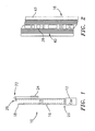
FIG. 1 is a schematic representation of an elevator system including the position reference system according to an embodiment of the present invention; and -
FIG. 2 is a schematic representation of a primary motion coupling used in the position reference system according to an embodiment of the present invention. - Referring now to
FIG. 1 , anelevator system 10 comprises anelevator car 12 which moves vertically within a hoistway 14 in a building structure. Aprimary motion coupling 16 extends from atermination point 18, throughidler sheaves 20 attached to thecar 12, over adrive sheave 22, to acounterweight 24. Thedrive sheave 22 may be driven using any suitable means known in the art to move theelevator car 12 vertically in the hoistway between a series of landings (not shown). Theprimary motion coupling 16 is used to suspend thecar 12 and may be a rope, a plurality of ropes, or a coated steel belt (CSB), such as that shown inFIG. 2 . Also as shown inFIG. 2 , theprimary motion coupling 16 may include a plurality ofcables 40 and/or acoating 42. - ln accordance with the present invention, the position reference system of the present invention includes a
code 26, as shown inFIG. 2 , which is affixed or embedded in theprimary motion coupling 16. The elevator positioning system further includes areader 28 at a fixed location. Thereader 28 is used to read thecode 26 and compute the absolute position, velocity, acceleration, and jerk of thecar 12. Thereader 28 may comprise any suitable reader known in the art. The type ofreader 28 which will be used will be a function of the nature of thecode 26. - The
code 26 and thereader 28 may also be used to directly measure the stretch or slip of theprimary motion coupling 16 of theelevator car 12. Stretch may be measured by direct measurement of the code. The code, when applied to a new primary motion coupling, will be of known length. Should the primary motion coupling stretch due to load or wear, the code indicia will stretch similarly. High resolution signal processing algorithms as well known in the art may be applied to measure the actual length of the code indicia and thereby directly measure stretch. Slip may be measured by comparison of the measured position to the drive commands. The controller of a conveyance uses feedback from a position reference system to generate drive commands to the primary motion actuator to affect position control of the conveyance. Ideally, the drive commands correspond exactly to a change in position. However, any slippage between the drive actuator and primary motion coupling results in a discrepancy between the change in position according to the position reference system and the change in position according to the drive commands, provided that the position reference system is independent of slippage. This discrepancy is a direct measure of slippage and slippage corresponds to wear on the primary motion actuator and primary motion coupling. - In a preferred embodiment of the present invention, the
reader 28 is positioned along theprimary motion coupling 16 at a fixed location between thedrive sheave 22 and thetermination point 18. ln this way, drive sheave slip is immaterial to the position measurement. Therefore, from the difference between the absolute position measurement and the drive commands, slip and corresponding wear may be calculated. This calculation may be through a look-up table, its equivalent functional representation, or by any of a variety of means well known in the art. - Compensation for stretch of the
primary motion coupling 16 may be directly measured from thecode 26 or may be estimated by an empirical function of load and temperature based on primary motion coupling tests. Depending on the accuracy of this estimation, a separate sill sensor (not shown) may be needed. lf so, then that information could be used in the estimation algorithm to improve position accuracy. - The
code 26 may be embedded in theprimary motion coupling 16, such as a coated steel belt, in a variety of different ways. For example, thecode 26 may be physical, optical, or magnetic marks or materials on the surface of theprimary motion coupling 16. It might be advantageous to have the marks along the edge of theprimary motion coupling 16 since the edge is not in contact with either thedrive sheave 22 or the idler sheaves 20, thus minimizing wear. Physical marks, such as grooves, are not preferred on the surface of theprimary motion coupling 16 due to possible induced noise. However, grooves of a given location, distribution, shape, etc., might be designed to an acceptable noise level, e. g. less than 48dB, and therefore permit their use as the codes for a position reference system. - The
code 26 may be physical, optical, or magnetic marks or materials embedded in thecoating 42 of aprimary motion coupling 16 such as the coated belt shown inFIG. 2 . This means theprimary motion coupling 16 may have to be slightly wider with no cables under a section of the coating, preferably in the middle. The embeddedcode 26 may be holes cut through theprimary motion coupling 16. Alternatively, theprimary motion coupling 16, such as the belt shown inFIG. 2 , may be fabricated in a laminated manner with one layer containing thecode 26. - The
code 26 may also be an additional cable or cord in theprimary motion coupling 16, such as the belt shown inFIG. 2 , with material properties that may be sensed through a coating, such as thebelt coating 42. - The
code 26 may also be changes or enhancements to one or more of thecables 40 within theprimary motion coupling 16, such as thecables 40 within the belt shown inFIG. 2 , with material properties that may be sensed through a coating, such asbelt coating 42. - The most preferred embodiment of the
code 26 comprises magnetic materials embedded in a coating on aprimary motion coupling 16, such as thebelt coating 42. lf these materials are sensitive to imposed magnetic fields, e. g. ferric oxide, then the entireprimary motion coupling 16 such as a coated steel belt, becomes a magnetic tape. ln this case, thereader 26 might also write, rewrite, or otherwise encode information on the belt. - Although the preferred embodiment uses an encoding on a suspension means between a moving cab and a fixed drive system, the invention will work equally well for a drive system attached to the moving
car 12 with suspension means attached to a fixed location. - Using the position referencing system of the present invention, there would be an installation savings over any approach that required separate hoistway equipment. An additional savings accrues from reduced inventory for the alternative equipment that is not needed. It is preferred that all encoded primary motion couplings be identical so as not to increase parts count.
- While the present invention has been described in the context of an elevator system, the position reference system of the present invention could be used on other conveyances.
- It is apparent that there has been provided in accordance with the present invention a device and method for absolute position reference system which fully satisfies the objects, means, and advantages set forth hereinbefore. While the present invention has been described in the context of specific embodiments thereof, other alternatives, variations and modifications will become apparent to those skilled in the art having read the foregoing description. Accordingly, it is intended to embrace those alternatives, modifications, and variations as fall within the scope of the appended claims.
Claims (13)
- A position reference system for use with a conveyance (12) having a suspension means (16), said system comprising:a code (26) on said suspension means (16); anda reader (28) in a fixed location for reading the code (26) and determining the position of said conveyance (12).
- A position reference system for use in an elevator system to determine the position of an elevator car (12) with respect to a fixed reference location, said system comprising a code (26) on a primary motion coupling (16) of said elevator car (12) and a reader (28) for reading said code (26).
- A position reference system according to claim 1 or 2, wherein said code (26) is affixed to or embedded within said suspension means or primary motion coupling (16).
- A position reference system according to claim 1 or 2, wherein said suspension means or primary motion coupling (16) comprises a coated belt and said code (26) comprises magnetic materials embedded in the belt coating.
- A position reference system according to claim 1 or 2, wherein said suspension means or primary motion coupling (16) comprises a coated steel belt.
- A position reference system according to claim 5, wherein said code (26) comprises at least one of a physical, optical, and magnetic indicia on a surface of said belt.
- A position reference system according to claim 5, wherein said code (26) comprises at least one of a physical, optical, and magnetic indicia embedded in a coating of the belt.
- A position reference system according to claim 1 or 2, wherein said suspension means or primary motion coupling (16) comprises a belt and said code comprises holes cut through said belt.
- A position reference system according to claim 1 or 2, wherein said suspension means or primary motion coupling (16) comprises a laminated belt with said code being contained within one layer.
- A position reference system according to claim 1 or 2, wherein said suspension means or primary motion coupling (16) comprises a belt and said code comprises at least one of a cable and cord in the belt having material properties that may be sensed through a coating on the belt.
- A position reference system according to claim 2, wherein said reader (28) is mounted within a hoistway (14) in a position between a termination point (18) of said primary motion coupling (16) and a drive sheave (22).
- An elevator system comprising the position reference system of any preceding claim, wherein the suspension means or primary motion coupling (16) is used to suspend the car (12).
- An elevator system according to claim 12, wherein the code (26) and the reader (28) are used to directly measure the stretch or slip of the suspension means or primary motion coupling (16) of the elevator car (12).
Applications Claiming Priority (2)
| Application Number | Priority Date | Filing Date | Title |
|---|---|---|---|
| EP03738915A EP1631517A4 (en) | 2003-05-15 | 2003-05-15 | Absolute position reference system |
| PCT/US2003/015244 WO2004106209A1 (en) | 2003-05-15 | 2003-05-15 | Absolute position reference system |
Related Parent Applications (1)
| Application Number | Title | Priority Date | Filing Date |
|---|---|---|---|
| EP03738915.2 Division | 2003-05-15 |
Publications (2)
| Publication Number | Publication Date |
|---|---|
| EP2348629A2 true EP2348629A2 (en) | 2011-07-27 |
| EP2348629A3 EP2348629A3 (en) | 2011-09-07 |
Family
ID=33488760
Family Applications (2)
| Application Number | Title | Priority Date | Filing Date |
|---|---|---|---|
| EP11159848A Withdrawn EP2348629A3 (en) | 2003-05-15 | 2003-05-15 | Absolute position reference system |
| EP03738915A Ceased EP1631517A4 (en) | 2003-05-15 | 2003-05-15 | Absolute position reference system |
Family Applications After (1)
| Application Number | Title | Priority Date | Filing Date |
|---|---|---|---|
| EP03738915A Ceased EP1631517A4 (en) | 2003-05-15 | 2003-05-15 | Absolute position reference system |
Country Status (6)
| Country | Link |
|---|---|
| EP (2) | EP2348629A3 (en) |
| JP (1) | JP2006525925A (en) |
| CN (1) | CN100575230C (en) |
| AU (1) | AU2003245277A1 (en) |
| HK (1) | HK1091798A1 (en) |
| WO (1) | WO2004106209A1 (en) |
Families Citing this family (11)
| Publication number | Priority date | Publication date | Assignee | Title |
|---|---|---|---|---|
| ES2445621T3 (en) * | 2005-03-22 | 2014-03-04 | Inventio Ag | Procedure for the detection of the state of the cabin of an elevator and installation of elevator, in which the procedure is applied |
| FI118382B (en) * | 2006-06-13 | 2007-10-31 | Kone Corp | Elevator system |
| MX2007012254A (en) * | 2006-10-12 | 2009-02-17 | Inventio Ag | System and method for detecting the position of a lift cage . |
| EP1911713B1 (en) * | 2006-10-12 | 2011-12-14 | Inventio AG | System and method for recording the position of a lift cabin |
| EP2322463A1 (en) * | 2009-11-12 | 2011-05-18 | Inventio AG | Lift assembly |
| EP2546181A1 (en) * | 2011-07-13 | 2013-01-16 | Inventio AG | Elevator installation and method for detecting the elevator car position. |
| CN104016201A (en) * | 2014-05-30 | 2014-09-03 | 日立电梯(中国)有限公司 | Absolute position detection device of elevator cab |
| CN104071665B (en) * | 2014-07-07 | 2017-09-15 | 日立电梯(中国)有限公司 | Lift car position detecting device and method |
| JP6399404B2 (en) | 2015-03-20 | 2018-10-03 | フジテック株式会社 | Car roll restraining device and elevator roll restraining method for elevator |
| EP3085653B1 (en) * | 2015-04-24 | 2019-04-10 | KONE Corporation | Elevator |
| CN107399650A (en) * | 2017-08-17 | 2017-11-28 | 卢卫民 | A kind of lift car position detecting device |
Citations (5)
| Publication number | Priority date | Publication date | Assignee | Title |
|---|---|---|---|---|
| US5023434A (en) | 1988-07-23 | 1991-06-11 | R. Stahl Fordertechnik Gmbh | Position indicating apparatus for transporters on tracks |
| US5138560A (en) | 1989-04-04 | 1992-08-11 | R. Stahl Fordertechnick Gmbh | Position indicating apparatus for crane ways, overhead conveyors, and the like |
| US5821477A (en) | 1995-01-20 | 1998-10-13 | Inventio Ag | Method and apparatus for generating elevator car position information |
| WO2001083352A2 (en) | 2000-05-01 | 2001-11-08 | Inventio Ag | Device for detecting the position of an elevator car |
| US6435315B1 (en) | 2000-12-11 | 2002-08-20 | Otis Elevator Company | Absolute position reference system for an elevator |
Family Cites Families (15)
| Publication number | Priority date | Publication date | Assignee | Title |
|---|---|---|---|---|
| US4085823A (en) * | 1975-11-03 | 1978-04-25 | Westinghouse Electric Corporation | Elevator system |
| US4218671A (en) * | 1977-10-10 | 1980-08-19 | Coal Industry (Patents) Limited | Mine cage position describer |
| JPH0133420B2 (en) * | 1980-02-08 | 1989-07-13 | Rejinarudo Kenesu Pein | |
| JPS5931274A (en) * | 1982-08-09 | 1984-02-20 | 株式会社東芝 | Detector for position of cage of elevator |
| JPS59102780A (en) * | 1982-12-01 | 1984-06-13 | 三菱電機株式会社 | Elevator device |
| ATE36143T1 (en) * | 1985-04-03 | 1988-08-15 | Inventio Ag | DEVICE FOR GENERATION OF SHAFT INFORMATION IN AN ELEVATOR. |
| FI111937B (en) * | 1993-12-28 | 2003-10-15 | Kone Corp | A method for determining the position of an elevator car |
| US5747755A (en) * | 1995-12-22 | 1998-05-05 | Otis Elevator Company | Elevator position compensation system |
| US5992574A (en) * | 1996-12-20 | 1999-11-30 | Otis Elevator Company | Method and apparatus to inspect hoisting ropes |
| JPH10318741A (en) * | 1997-05-16 | 1998-12-04 | Kobe Steel Ltd | Method and apparatus for measurement of elongation of wire rope |
| US5925859A (en) * | 1997-08-06 | 1999-07-20 | Interface Products Co., Inc. | Landing control system |
| DE10041035A1 (en) * | 2000-08-22 | 2002-03-07 | Heinrich Bader | Device and method for mechanizing cable and brochure hoists, especially in the stage area |
| JP2002167133A (en) * | 2000-11-29 | 2002-06-11 | Toshiba Corp | Position detection device for elevator |
| SG96681A1 (en) * | 2001-02-20 | 2003-06-16 | Inventio Ag | Method of generating hoistway information to serve an elevator control |
| DE10141412C2 (en) * | 2001-08-23 | 2003-12-04 | Kone Corp | Method and device for speed monitoring of moving components of passenger conveyor systems |
-
2003
- 2003-05-15 AU AU2003245277A patent/AU2003245277A1/en not_active Abandoned
- 2003-05-15 EP EP11159848A patent/EP2348629A3/en not_active Withdrawn
- 2003-05-15 EP EP03738915A patent/EP1631517A4/en not_active Ceased
- 2003-05-15 CN CN03826457A patent/CN100575230C/en not_active Expired - Fee Related
- 2003-05-15 WO PCT/US2003/015244 patent/WO2004106209A1/en active Application Filing
- 2003-05-15 JP JP2005500391A patent/JP2006525925A/en active Pending
-
2006
- 2006-11-10 HK HK06112433.4A patent/HK1091798A1/en not_active IP Right Cessation
Patent Citations (5)
| Publication number | Priority date | Publication date | Assignee | Title |
|---|---|---|---|---|
| US5023434A (en) | 1988-07-23 | 1991-06-11 | R. Stahl Fordertechnik Gmbh | Position indicating apparatus for transporters on tracks |
| US5138560A (en) | 1989-04-04 | 1992-08-11 | R. Stahl Fordertechnick Gmbh | Position indicating apparatus for crane ways, overhead conveyors, and the like |
| US5821477A (en) | 1995-01-20 | 1998-10-13 | Inventio Ag | Method and apparatus for generating elevator car position information |
| WO2001083352A2 (en) | 2000-05-01 | 2001-11-08 | Inventio Ag | Device for detecting the position of an elevator car |
| US6435315B1 (en) | 2000-12-11 | 2002-08-20 | Otis Elevator Company | Absolute position reference system for an elevator |
Also Published As
| Publication number | Publication date |
|---|---|
| EP1631517A4 (en) | 2009-01-07 |
| EP1631517A1 (en) | 2006-03-08 |
| WO2004106209A1 (en) | 2004-12-09 |
| EP2348629A3 (en) | 2011-09-07 |
| CN100575230C (en) | 2009-12-30 |
| JP2006525925A (en) | 2006-11-16 |
| AU2003245277A1 (en) | 2005-01-21 |
| HK1091798A1 (en) | 2007-01-26 |
| CN1771182A (en) | 2006-05-10 |
Similar Documents
| Publication | Publication Date | Title |
|---|---|---|
| US7540357B2 (en) | Position reference system for elevators | |
| US8408364B2 (en) | Elevator hoistway speed identifier with measured property | |
| CN100480160C (en) | Elevator system with a device for determining the position of an elevator cabin and method for operating the same | |
| JP5416331B2 (en) | Elevator installation having a cage and a device for determining the cage position, and method of operating such an elevator installation | |
| US7597176B2 (en) | Elevator car position determining system and method using a signal filling technique | |
| US8439167B2 (en) | Spacing control for two elevator cars in a common shaft | |
| US6877587B2 (en) | Equipment for determining elevator car position | |
| US20130001023A1 (en) | Elevator device, building and position determining device | |
| EP2348629A2 (en) | Absolute position reference system | |
| EP2985254B1 (en) | Positioning apparatus for elevators | |
| US20040174161A1 (en) | Position sensing system | |
| JP2013530905A (en) | Speed position detection system | |
| KR100730271B1 (en) | Absolute position reference system | |
| CN114206759B (en) | Method and device for determining the current exact position of an elevator car in an elevator shaft | |
| CN113493149B (en) | Elevator safety system | |
| Marchesi et al. | Sensor systems in modern high-rise elevators |
Legal Events
| Date | Code | Title | Description |
|---|---|---|---|
| PUAI | Public reference made under article 153(3) epc to a published international application that has entered the european phase |
Free format text: ORIGINAL CODE: 0009012 |
|
| AC | Divisional application: reference to earlier application |
Ref document number: 1631517 Country of ref document: EP Kind code of ref document: P |
|
| AK | Designated contracting states |
Kind code of ref document: A2 Designated state(s): AT BE BG CH CY CZ DE DK EE ES FI FR GB GR HU IE IT LI LU MC NL PT RO SE SI SK TR |
|
| PUAL | Search report despatched |
Free format text: ORIGINAL CODE: 0009013 |
|
| AK | Designated contracting states |
Kind code of ref document: A3 Designated state(s): AT BE BG CH CY CZ DE DK EE ES FI FR GB GR HU IE IT LI LU MC NL PT RO SE SI SK TR |
|
| RIC1 | Information provided on ipc code assigned before grant |
Ipc: B66B 7/06 20060101ALI20110803BHEP Ipc: B66B 1/34 20060101ALI20110803BHEP Ipc: H02P 5/00 20060101AFI20110803BHEP |
|
| REG | Reference to a national code |
Ref country code: HK Ref legal event code: DE Ref document number: 1154314 Country of ref document: HK |
|
| STAA | Information on the status of an ep patent application or granted ep patent |
Free format text: STATUS: THE APPLICATION IS DEEMED TO BE WITHDRAWN |
|
| 18D | Application deemed to be withdrawn |
Effective date: 20120308 |
|
| REG | Reference to a national code |
Ref country code: HK Ref legal event code: WD Ref document number: 1154314 Country of ref document: HK |