EP2353629A1 - Connector for containers containing medical agents - Google Patents
Connector for containers containing medical agents Download PDFInfo
- Publication number
- EP2353629A1 EP2353629A1 EP20100152921 EP10152921A EP2353629A1 EP 2353629 A1 EP2353629 A1 EP 2353629A1 EP 20100152921 EP20100152921 EP 20100152921 EP 10152921 A EP10152921 A EP 10152921A EP 2353629 A1 EP2353629 A1 EP 2353629A1
- Authority
- EP
- European Patent Office
- Prior art keywords
- connector
- piercing element
- container
- connection region
- guide element
- Prior art date
- Legal status (The legal status is an assumption and is not a legal conclusion. Google has not performed a legal analysis and makes no representation as to the accuracy of the status listed.)
- Withdrawn
Links
Images


Classifications
-
- A—HUMAN NECESSITIES
- A61—MEDICAL OR VETERINARY SCIENCE; HYGIENE
- A61J—CONTAINERS SPECIALLY ADAPTED FOR MEDICAL OR PHARMACEUTICAL PURPOSES; DEVICES OR METHODS SPECIALLY ADAPTED FOR BRINGING PHARMACEUTICAL PRODUCTS INTO PARTICULAR PHYSICAL OR ADMINISTERING FORMS; DEVICES FOR ADMINISTERING FOOD OR MEDICINES ORALLY; BABY COMFORTERS; DEVICES FOR RECEIVING SPITTLE
- A61J1/00—Containers specially adapted for medical or pharmaceutical purposes
- A61J1/14—Details; Accessories therefor
- A61J1/20—Arrangements for transferring or mixing fluids, e.g. from vial to syringe
- A61J1/2003—Accessories used in combination with means for transfer or mixing of fluids, e.g. for activating fluid flow, separating fluids, filtering fluid or venting
- A61J1/2006—Piercing means
- A61J1/201—Piercing means having one piercing end
-
- A—HUMAN NECESSITIES
- A61—MEDICAL OR VETERINARY SCIENCE; HYGIENE
- A61J—CONTAINERS SPECIALLY ADAPTED FOR MEDICAL OR PHARMACEUTICAL PURPOSES; DEVICES OR METHODS SPECIALLY ADAPTED FOR BRINGING PHARMACEUTICAL PRODUCTS INTO PARTICULAR PHYSICAL OR ADMINISTERING FORMS; DEVICES FOR ADMINISTERING FOOD OR MEDICINES ORALLY; BABY COMFORTERS; DEVICES FOR RECEIVING SPITTLE
- A61J1/00—Containers specially adapted for medical or pharmaceutical purposes
- A61J1/05—Containers specially adapted for medical or pharmaceutical purposes for collecting, storing or administering blood, plasma or medical fluids ; Infusion or perfusion containers
- A61J1/10—Bag-type containers
-
- A—HUMAN NECESSITIES
- A61—MEDICAL OR VETERINARY SCIENCE; HYGIENE
- A61J—CONTAINERS SPECIALLY ADAPTED FOR MEDICAL OR PHARMACEUTICAL PURPOSES; DEVICES OR METHODS SPECIALLY ADAPTED FOR BRINGING PHARMACEUTICAL PRODUCTS INTO PARTICULAR PHYSICAL OR ADMINISTERING FORMS; DEVICES FOR ADMINISTERING FOOD OR MEDICINES ORALLY; BABY COMFORTERS; DEVICES FOR RECEIVING SPITTLE
- A61J1/00—Containers specially adapted for medical or pharmaceutical purposes
- A61J1/14—Details; Accessories therefor
- A61J1/1406—Septums, pierceable membranes
-
- A—HUMAN NECESSITIES
- A61—MEDICAL OR VETERINARY SCIENCE; HYGIENE
- A61J—CONTAINERS SPECIALLY ADAPTED FOR MEDICAL OR PHARMACEUTICAL PURPOSES; DEVICES OR METHODS SPECIALLY ADAPTED FOR BRINGING PHARMACEUTICAL PRODUCTS INTO PARTICULAR PHYSICAL OR ADMINISTERING FORMS; DEVICES FOR ADMINISTERING FOOD OR MEDICINES ORALLY; BABY COMFORTERS; DEVICES FOR RECEIVING SPITTLE
- A61J1/00—Containers specially adapted for medical or pharmaceutical purposes
- A61J1/14—Details; Accessories therefor
- A61J1/1475—Inlet or outlet ports
- A61J1/1481—Inlet or outlet ports with connection retaining means, e.g. thread or snap-fit
-
- A—HUMAN NECESSITIES
- A61—MEDICAL OR VETERINARY SCIENCE; HYGIENE
- A61M—DEVICES FOR INTRODUCING MEDIA INTO, OR ONTO, THE BODY; DEVICES FOR TRANSDUCING BODY MEDIA OR FOR TAKING MEDIA FROM THE BODY; DEVICES FOR PRODUCING OR ENDING SLEEP OR STUPOR
- A61M39/00—Tubes, tube connectors, tube couplings, valves, access sites or the like, specially adapted for medical use
- A61M39/22—Valves or arrangement of valves
- A61M39/221—Frangible or pierceable closures within tubing
-
- A—HUMAN NECESSITIES
- A61—MEDICAL OR VETERINARY SCIENCE; HYGIENE
- A61M—DEVICES FOR INTRODUCING MEDIA INTO, OR ONTO, THE BODY; DEVICES FOR TRANSDUCING BODY MEDIA OR FOR TAKING MEDIA FROM THE BODY; DEVICES FOR PRODUCING OR ENDING SLEEP OR STUPOR
- A61M5/00—Devices for bringing media into the body in a subcutaneous, intra-vascular or intramuscular way; Accessories therefor, e.g. filling or cleaning devices, arm-rests
- A61M5/14—Infusion devices, e.g. infusing by gravity; Blood infusion; Accessories therefor
- A61M5/162—Needle sets, i.e. connections by puncture between reservoir and tube ; Connections between reservoir and tube
-
- A—HUMAN NECESSITIES
- A61—MEDICAL OR VETERINARY SCIENCE; HYGIENE
- A61J—CONTAINERS SPECIALLY ADAPTED FOR MEDICAL OR PHARMACEUTICAL PURPOSES; DEVICES OR METHODS SPECIALLY ADAPTED FOR BRINGING PHARMACEUTICAL PRODUCTS INTO PARTICULAR PHYSICAL OR ADMINISTERING FORMS; DEVICES FOR ADMINISTERING FOOD OR MEDICINES ORALLY; BABY COMFORTERS; DEVICES FOR RECEIVING SPITTLE
- A61J1/00—Containers specially adapted for medical or pharmaceutical purposes
- A61J1/14—Details; Accessories therefor
- A61J1/1468—Containers characterised by specific material properties
-
- A—HUMAN NECESSITIES
- A61—MEDICAL OR VETERINARY SCIENCE; HYGIENE
- A61J—CONTAINERS SPECIALLY ADAPTED FOR MEDICAL OR PHARMACEUTICAL PURPOSES; DEVICES OR METHODS SPECIALLY ADAPTED FOR BRINGING PHARMACEUTICAL PRODUCTS INTO PARTICULAR PHYSICAL OR ADMINISTERING FORMS; DEVICES FOR ADMINISTERING FOOD OR MEDICINES ORALLY; BABY COMFORTERS; DEVICES FOR RECEIVING SPITTLE
- A61J1/00—Containers specially adapted for medical or pharmaceutical purposes
- A61J1/14—Details; Accessories therefor
- A61J1/1475—Inlet or outlet ports
- A61J1/1487—Inlet or outlet ports with friction fit, e.g. connecting tubes directly to a protruding port
-
- A—HUMAN NECESSITIES
- A61—MEDICAL OR VETERINARY SCIENCE; HYGIENE
- A61J—CONTAINERS SPECIALLY ADAPTED FOR MEDICAL OR PHARMACEUTICAL PURPOSES; DEVICES OR METHODS SPECIALLY ADAPTED FOR BRINGING PHARMACEUTICAL PRODUCTS INTO PARTICULAR PHYSICAL OR ADMINISTERING FORMS; DEVICES FOR ADMINISTERING FOOD OR MEDICINES ORALLY; BABY COMFORTERS; DEVICES FOR RECEIVING SPITTLE
- A61J1/00—Containers specially adapted for medical or pharmaceutical purposes
- A61J1/14—Details; Accessories therefor
- A61J1/20—Arrangements for transferring or mixing fluids, e.g. from vial to syringe
- A61J1/2003—Accessories used in combination with means for transfer or mixing of fluids, e.g. for activating fluid flow, separating fluids, filtering fluid or venting
- A61J1/2048—Connecting means
- A61J1/2051—Connecting means having tap means, e.g. tap means activated by sliding
Definitions
- the invention relates to a connector for medical drug-containing container, which makes it possible to transfer active ingredient from one container to another container.
- the EP 2 095 805 A2 discloses a medical drug containment connector that includes a first port area for connecting a vial, a second port area for connection to a flexible bag, and an axially movable piercing element configured as a double ended sharpened cannula.
- the piercing element is mounted axially displaceably in a first housing section of a housing of the connector.
- the first housing section is mounted so as to be telescopically displaceable on a second housing section. In the initial position of the connector, the first housing section and the second housing section are pulled apart. By connecting a glass bottle in the first connection area and exerting pressure on the glass bottle, the first housing section moves relative to the second housing section.
- the glass bottle occlusive membrane strikes one end of the piercing element.
- the piercing element is entrained during advancement of the glass bottle until it meets with its other end on a membrane closing the flexible bag.
- both the membrane on the side of the flexible bag and the membrane of the glass bottle are pierced by the piercing element.
- a stop for the movement of the piercing element limits the movement of the piercing element and ensures that not only the bag-side membrane, but also the membrane of the glass bottle is opened.
- this connector includes movable parts with the two housing sections, which are against each other must be sealed. Furthermore, the connector comprises a plurality of elements that make the manufacture of the connector expensive and expensive.
- the connector for medical active substance-containing container comprises a first connection region for the connection of a first container, a guide element, a piercing element and a partition, wherein the guide element has a trained for the transfer of a medical drug channel, the piercing element at least partially disposed in the channel is guided axially movable within the channel by the guide element, and by connecting a container, the piercing element from a starting position in which the piercing element does not open the dividing wall, in an end position in which the piercing element opens the partition for transferring a medical drug, is movable.
- the guide element forms both the channel through which an active substance can be transferred, as well as forms a bearing in which the piercing element is axially movable, the guide element can assume a dual function.
- the number of elements of the connector can be reduced and the connector can be manufactured inexpensively. Also, in this way the number of interfaces can be reduced and the handling of the connector can be improved.
- the connector according to the invention makes it possible, in particular, to transfer the medical active substance without risk of contamination.
- the containers which can be connected or connected through the connector can be both closed containers, for example glass bottles, plastic bottles or bags, in particular flexible bags, or "open" containers, for example catheters or other lines, as used, for example, in the infusion, Transfusion, clinical nutrition, oncology, dialysis or other medical fields are used.
- the medical active substance, by means of the Connector can be transferred from one container to another container, for example, a liquid or even a powder.
- the partition may be a flexible partition, for example of an elastic material, in particular in the form of a membrane, but also, which is preferred, a rigid partition, which is broken or pierced by the piercing element.
- the piercing element and the guide element are designed such that a clearance for the transfer of a medical active substance remains between an outer surface of the piercing element and an inner surface of the guide element forming the channel.
- the piercing element and the guide element are designed in such a way that the transfer of the medical active substance takes place additionally or exclusively through the piercing element.
- the piercing element may be solid or hollow body for the respective purpose. A combination of hollow body and solid body is also possible in principle.
- the profile of the piercing element preferably changes along its axis, wherein the end wall facing the partition wall is formed for breaking or piercing the partition wall, and the end portion facing the container to be connected is designed such that a pressure can be exerted on the end section by means of the container the piercing element can be pressed against the partition wall.
- the end wall facing the partition wall may be formed, for example, tapered with a linear or cross-shaped profile, the other end portion to be formed to form a support surface with, for example, a cross-shaped or round profile.
- the end wall facing the dividing wall may be formed with a facet cut or have a hammered tip
- the guide element and the partition are made in one piece, in one particularly preferred embodiment in one piece.
- the connector comprises a housing forming the first connection region.
- housing, guide element and partition are integrally formed, particularly preferably in one piece.
- piercing element, guide element, dividing wall and / or housing are produced from a plastic, preferably polypropylene (PP) or a blend of polypropylene and styrene / ethylene-butylene / styrene (SEBS).
- PP polypropylene
- SEBS ethylene-butylene / styrene
- piercing element, guide element, partition wall and / or housing may be injection-molded parts.
- the piercing element may alternatively be made of, for example, polycarbonate (PC) or polystyrene (PS).
- the guide element comprises an end section which is designed to pierce a membrane of a container which can be connected to the first connection region, for example for piercing a rubber stopper of a glass vial.
- the guide element thus includes another function.
- the first connection region is designed as a Luer connection of a Luer lock, in particular as a male part.
- the guide element is in this case partially or completely formed by the central cone of the Luer connector.
- Fig.1 a longitudinal section through a first embodiment of a erfindunbicen connector
- Fig. 2 a cut through the in Fig. 1 shown connector along the section line CC.
- Fig. 3 a first perspective view of the in the Fig. 1 shown connector
- Fig. 4 a second perspective view of the in the Fig. 1 shown connector
- Fig. 5 a portion of the piercing element of the in Fig. 1 shown connector
- Fig. 6 a perspective view of the cut along the longitudinal axis, in Fig. 1 shown connector in an initial state
- Fig. 7 a perspective view of the cut along the longitudinal axis, in Fig. 1 shown connector before connecting a glass vial
- Fig. 8 a perspective view of the cut along the longitudinal axis, in Fig. 1 shown connector with the glass vial in a docking position,
- Fig. 9 a perspective view of the cut along the longitudinal axis, in Fig. 1 shown connector with the glass vial in connected end position,
- Fig. 10 a perspective view of the first terminal portion of the in Fig. 1 shown connector
- Fig. 11 a side view of a second embodiment of a connector according to the invention with a connector connected to the connector Luer female part
- Fig. 12 a perspective view of the in Fig. 11 shown connector with Luer female part
- Fig. 14 a longitudinal section through the in Fig. 11 shown connector with Luer female part
- FIG. 15 an enlarged view of the in Fig. 14 marked section A
- Fig. 16 a perspective view of the cut along the longitudinal axis, in Fig. 11 shown connector before connecting the Luer-Female part,
- Fig. 17 a perspective view of the cut along the longitudinal axis, in Fig. 11 shown connector with attached luer female part,
- Fig. 18 a perspective view of the piercing element of in Fig. 11 shown connector.
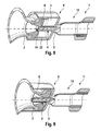
- Fig. 1 to 10 show in various views a first embodiment of a connector 1 according to the invention for medical drug-containing container.
- the connector 1 comprises a first connection region 3 for the connection of a first container, a guide element 4, a piercing element 5, a partition wall 6 and a second connection region for the connection of a second container.
- the first connection region 3 is designed here for the connection of a medical glass vial.
- the second connection region 12 is designed here for the connection of a flexible bag.
- the first connection region 3 and / or the second connection region 12 may of course also be designed for other containers, for example plastic bottles or transfer systems.
- the connector 1 comprises a housing 9 with a substantially hollow cylindrical housing portion 10 forming a first connection region 3 and a housing bottom 11.
- the guide element 4 is designed as a tubular hollow body with a channel 7 for the transfer of a medical active substance and in the center of the housing bottom 11 connected to the housing bottom 11.
- the one end of the guide element ends at the housing bottom 11, the other end protrudes into the connection region 3 and thus into the inner region of the housing section 3.
- the end section 8 of the guide element 4 projecting into the connection region 3 is sharpened or sharpened in order to pierce a membrane 14 of a container 2 to be connected in the connection region 3.
- Housing section 10 and guide element 4 are arranged axially of a common axis of symmetry 15.
- the connector 1 comprises a connection means 13, which forms the second connection region 12.
- the connecting means 13 is tubular, arranged along the axis of symmetry 15 and connected at one end to the back of the housing base 11 opposite the connection region 3.
- the connecting means 13 comprises two mirror-symmetrically formed welding lugs 16 for connecting the connecting means 13 with a flexible plastic bag, not shown.
- the connecting means 13 comprises two laterally, along the axis of symmetry 15 extending reinforcing webs 17 which extend mirror-symmetrically arranged from the bottom 11 to the welding straps 16 and have the purpose to stiffen the connecting means.
- the partition 6 is formed in the form of a membrane. It is arranged between the first connection region 3 and the second connection region 12 and, in the closed state, prevents the transport of a medicinal active substance between these two regions.
- the dividing wall 6 is arranged at the end of the guide element 4 facing away from the first connection region 3 and terminates flush with the rear side of the housing bottom 11.
- an arrangement of Partition 6 at one end of the channel 7 is alternatively also an arrangement of the partition wall 6 within the channel 7 of the guide element 4 possible.
- the partition 6 can be arranged such that it lifts off from the housing bottom 11, for example, is arranged like a lid on the opening of the channel 7.
- the partition wall 6 can be fastened to the housing bottom 11 via at least one predetermined breaking point, so that the dividing wall 6 can be broken at the at least one predetermined breaking point by the piercing element 5 and the channel 7 is opened in this way. A piercing of the partition 6 can be omitted in this case.
- the partition 6 is formed as a wall with sufficiently thin wall thickness to be pierced by the piercing element 5 and / or broken.
- the partition wall is designed such that it remains open after piercing / breaking when pulling out of the piercing element 5, which is preferred. It is also possible to form the partition 6 such that it can close after pulling out the piercing element 5.
- Housing 9, guide member 4, partition 6 and connecting means 12 are in this embodiment, one-piece and one-piece made of plastic, here made of PP or a blend of PP and SEBS, as an injection molded part, whereby the connector is particularly inexpensive to produce.
- plastic here made of PP or a blend of PP and SEBS
- the connector is particularly inexpensive to produce.
- a multi-part construction and / or a structure of several different materials is also possible.
- the piercing element 5 is formed in this embodiment as a solid rod.
- the piercing element is arranged in the channel 7 and is guided axially movably within the channel 7 by the guide element 4. Between the inner surface of the channel 7 and the outer surface of the piercing element 5 there is an axially extending free space, which has a sufficient cross-section to allow medical drug to pass sufficiently fast between the first connection region 3 and the second connection region 12.
- the piercing element 5 here has a cross-shaped profile, which in his outer dimensions is adapted to the inner diameter of the tubular guide element 4, so that the piercing element 5 is not tilted.
- the piercing element 5 can be used, for example, profiles in triangular shape, star shape, square shape and / or cylindrical shape.
- the piercing element 5 can also be partially or completely formed as a hollow body and the transport of the medical active substance can be effected partially or completely through the piercing element 5.
- the guide member 4 may alternatively be formed with other profiles, such as square or rectangular.
- the piercing element 5 is detachably prefixed.
- the piercing element 5 comprises two opposing projections 18 which, in the initial position, releasably engage in two corresponding grooves 19 in the guide element 4.
- the piercing element 4 can be released from the starting position and transferred to an end position.
- the piercing element 4 opens the dividing wall 6, see also Fig.
- the guide element 5 has two further grooves 20, into which the piercing element 4 can engage after opening the partition wall 6 and which prevent the piercing element 4 from undesirably becoming detached from the guide element 4.
- only one groove or further grooves may be provided on the piercing element 4, wherein in the case of a plurality of grooves, these may be arranged offset, for example.
- the piercing element can be prefixed, for example, by an excess in the guide element.
- the piercing element 5 is sharpened or sharpened at its end facing the dividing wall 6.
- the partition 6 facing away from the piercing 5 forms a support surface to receive the pressure of a container to be connected as large as possible and to prevent the piercing element 5 undesirably penetrates into the container, for example, pierces a rubber stopper closure of the container.
- the partition 6 remote from the end of the piercing element 5 is formed as a flat surface in this case.
- the piercing element 5 is in this embodiment, in one piece and in one piece made of a plastic, preferably made of PP, PC or PS, as an injection molded part.
- the piercing element 5 may also consist of several parts and / or of other materials, for example also of a metal, and / or of a plurality of materials.
- the connector comprises a releasable cover film 21, which closes the first connection region 3 and protects against contamination, for example against contamination by unintentional contact.
- the cover film may be, for example, a manually peelable aluminum foil or plastic film.
- FIGS. 6 to 9 show the connection of a glass vial 2 to the connector 1.
- Fig. 6 shows the connector 1 in the initial state.
- the cover 21 is first removed manually. Subsequently, the glass bottle is inserted with its neck in the first connection area 3, see Fig. 7 .
- the glass bottle 2 exerts on the over the guide member 4 projecting, the glass bottle 2 facing the end of the piercing element 5 axial pressure on the piercing element 5, which pushes the piercing element 5 with its the partition wall 6 facing the end against the partition wall 6 until the piercing element 5 has broken through the partition wall 6 by the pressure.
- the piercing element 5 is displaced axially until the container 2 reaches an upstream Be Strukturerandockposition, see FIG.
- the housing 9 comprises a plurality of axially extending, on the inside of the Housing section 10 extending clamping webs 22 which connect the glass bottle when inserted into the connection area by clamping with the connector 1.
- the membrane 14 arranged in the neck of the container 2 here a rubber stopper, has not yet pierced, so that in this position a transfer of a medicinal active substance is still prevented.
- the container 2 can be detached from the connector 1, without this has already been opened. The latter is particularly advantageous if the container contains 2 expensive active ingredients.
- the membrane 14 Upon further insertion of the container 2 into the connection region 3, the membrane 14 is pierced by the cannula-like end section 8 of the guide element 4, see FIG. 9 , An active substance in the container 2, for example a liquid or a powder, can now be transferred by means of the connector 1 and, for example, diluted and / or dissolved, for example in a flexible bag connected to the connecting means 13, or conversely, an active ingredient in the container 2 are conducted.
- the container 2 reaches an end position in which one or more projections 23 on the inside of the housing portion 10, see for example Fig. 8 , The container 2 engage behind the form-fitting manner at its neck and prevent slipping out of the container 2 from the first connection region 3 of the connector 1.
- a further undercut may be provided, for example by additional projections, which fixes the container 2 already in the docking position to form a positive connection.
- the clamping webs 22 may also be present in this variant, but alternatively can be dispensed with. Such a second undercut facilitates the connection of containers of different dimensions with the connector.
- the container 2 may be preassembled in the docking position on the connector.
- the preassembled container 2, the connector 1 and a container connected to the connector 1, in particular a bag, can be enclosed in a bag as a set. This allows for a secure Mixing the components outside the laminar flow range without the risk of contamination.
- FIGS. 11 to 18 show a second embodiment of a connector 1 'for medical drug-containing container according to the invention in various views. Elements or components corresponding to those of the first embodiment have been identified by the same reference numerals used to identify the components of the first embodiment.
- the connector 1 ' according to the second embodiment includes a first terminal portion 3', a guide member 4 ', a piercing member 5', a partition wall 6, and a second terminal portion 12.
- the second terminal portion 12 is formed by a connection means 13 similar to that of the first embodiment equivalent.
- the first connection region 3 ' is designed as a Luer connection of a Luer lock (ISO 594/1 or ISO 594/2), here as a Luer-Male part.
- Connection area 3 ', guide element 4', piercing element 5 'and connecting means 13 are arranged along the common axis of symmetry 15.
- the connector 1 ' comprises a housing 9' with a substantially cylindrical housing portion 10 'with an internal thread and a housing bottom 11', which form the connection area 3 '.
- the guide element 4 ' is designed as a hollow outer cone and projects into the connection area 3'. By forming a hollow body, the guide element 4 'comprises an inner channel 7, which is provided for the transfer of a medical drug.
- the guide element 4 ' is in the center of the housing bottom 11' connected to the housing bottom 11 '.
- the partition wall 6 is arranged according to the partition wall 6 according to the first embodiment in the plane of the housing bottom 11 'and formed accordingly. In the closed state, the partition wall 6 prevents transport of a medicinal active substance between the first connection region 3 'and the second connection region 12.
- the piercing element 5 ' is tube-shaped designed as a hollow body.
- the piercing element 5 ' is arranged in sections in the channel 7 and is guided axially movably within the channel 7 by the guide element 4'.
- the outer diameter of the piercing element 5 ' is adapted in the guided section to the inner diameter of the guide element 4' for as play-free storage.
- the piercing element 5' has a collar 24, see Fig. 5 , at its end facing away from the first connection region 3 ', the piercing element 5' is sharpened or sharpened for easier severing of the dividing wall 6.
- the collar 24 In a starting position in which the piercing element 5 'does not open the dividing wall 6, see Fig. 16 , the collar 24 is spaced from the guide element 4 ', in an end position in which the piercing element 5' opens the partition 6 for transferring a medicinal agent, the collar 24 rests on the upper edge 25 of the guide element 4 ', see Fig. 15 and 17 , whereby a further insertion of the piercing element 5 'is blocked in the guide element 4'.
- the piercing element 5 ' may also be formed as a solid body, for example with a cross-shaped, star-shaped, triangular or similar profile. In this case, a free space remaining between the inner surface of the guide element 4 'and the outer surface of the piercing element 5' can be used for the transport of the medical active substance.
- Housing 9 ', guide element 4', partition 6 and connecting means 6 are in this embodiment as a one-piece and one-piece injection molded part made of a plastic, preferably PP or a PP-SEBS blend manufactured.
- a plastic preferably PP or a PP-SEBS blend manufactured.
- the piercing element 5 ' is likewise a one-piece and one-piece injection-molded part made of plastic, preferably PP. PC or PS.
- a multi-part structure and the use of other and / or different materials as an alternative would be possible in principle.
- the illustrated figures show in addition to the connector 1 ', an element of a container, here a Luer-female part 2', which is connected to the connector 1 'or is connected.
- the luer female part 2 ' may be part of a syringe or a transfer system, for example.
- Fig. 16 shows the state after the attachment of the luer female part 2 'and before locking the luer female part 2' with the luer male part of the connector 1 '.
- the guide element 4 'with the protruding piercing element 5' is already partially inserted into the inner cone of the female luer part 2 '.
- the outer diameter of the collar 24 of the piercing element 5 ' is adapted to the diameter of the inner cone of the luer female part 2', so that the collar 24 is not completely pushed through the inner cone, but is previously clamped by the tapered inner cone at its outer edge , here almost at the end of the inner cone.
- connection area 3 'of the connector 1' with piercing element 5 ' can be covered by a manually detachable cap (not shown) for protection against contamination and / or protection against accidental opening of the dividing wall 6 by movement of the piercing element 5'.
- the piercing element 5 ' is preferably prefixed in its extended initial position, for example by means of a tongue and groove connection similar to that of the first Embodiment. A fixation of the piercing element 5 'in the end position is possible, for example, to prevent falling out of the piercing element 5' upon release of the female part 2 '.
- the connectors 1, 1 'according to the invention have the advantage that they are inexpensive to produce. Furthermore, a sterile connection between two containers can be produced manually in a simple manner safely and quickly. For rapid transfer of a medical active ingredient, guide element 4, 4 'and piercing element 5, 5' can be formed with suitable profiles.
Abstract
Description
Die Erfindung betrifft einen Konnektor für medizinischen Wirkstoff enthaltende Behälter, der es ermöglicht, Wirkstoff aus einem Behälter in einen anderen Behälter zu überführen.The invention relates to a connector for medical drug-containing container, which makes it possible to transfer active ingredient from one container to another container.
Die
Nachteilig an diesem Konnektor ist, dass dieser mit den beiden Gehäuseabschnitten bewegliche Teile umfasst, die gegeneinander abgedichtet werden müssen. Des Weiteren umfasst der Konnektor eine Vielzahl von Elementen, die die Herstellung des Konnektors aufwendig und teuer machen.A disadvantage of this connector is that this includes movable parts with the two housing sections, which are against each other must be sealed. Furthermore, the connector comprises a plurality of elements that make the manufacture of the connector expensive and expensive.
Der erfindungsgemäße Konnektor für medizinischen Wirkstoff enthaltende Behälter umfasst einen ersten Anschlussbereich für den Anschluss eines ersten Behälters, ein Führungselement, ein Durchstechelement und eine Trennwand, wobei das Führungselement einen für die Überführung eines medizinischen Wirkstoffes ausgebildeten Kanal aufweist, das Durchstechelement zumindest abschnittsweise in dem Kanal angeordnet ist und innerhalb des Kanals vom Führungselement axial beweglich geführt wird, und durch das Anschließen eines Behälters das Durchstechelement von einer Ausgangsstellung, in der das Durchstechelement die Trennwand nicht öffnet, in eine Endstellung, in der das Durchstechelement die Trennwand zum Überführen eines medizinischen Wirkstoffs öffnet, bewegbar ist.The connector for medical active substance-containing container according to the invention comprises a first connection region for the connection of a first container, a guide element, a piercing element and a partition, wherein the guide element has a trained for the transfer of a medical drug channel, the piercing element at least partially disposed in the channel is guided axially movable within the channel by the guide element, and by connecting a container, the piercing element from a starting position in which the piercing element does not open the dividing wall, in an end position in which the piercing element opens the partition for transferring a medical drug, is movable.
Dadurch, dass das Führungselement sowohl den Kanal ausbildet, durch den ein Wirkstoff überführt werden kann, als auch ein Lager ausbildet, in dem das Durchstechelement axial beweglich verschiebbar ist, kann das Führungselement eine Doppelfunktion übernehmen. Hierdurch kann die Anzahl der Elemente des Konnektors reduziert und der Konnektor kostengünstig hergestellt werden. Auch kann auf diese Weise die Anzahl der Schnittstellen reduziert und das Handling des Konnektors verbessert werden. Der erfindungsgemäße Konnektor ermöglicht insbesondere eine Überführung des medizinischen Wirkstoffes ohne Kontaminationsrisiko.Characterized in that the guide element forms both the channel through which an active substance can be transferred, as well as forms a bearing in which the piercing element is axially movable, the guide element can assume a dual function. As a result, the number of elements of the connector can be reduced and the connector can be manufactured inexpensively. Also, in this way the number of interfaces can be reduced and the handling of the connector can be improved. The connector according to the invention makes it possible, in particular, to transfer the medical active substance without risk of contamination.
Die Behälter, die durch den Konnektor verbunden oder angeschlossen werden können, können sowohl geschlossene Behälter, beispielsweise Glasflaschen, Kunststoffflaschen oder Beutel, insbesondere flexible Beutel, oder "offene" Behälter, beispielsweise Katheter oder sonstige Leitungen, sein, wie sie beispielsweise in der Infusion, Transfusion, der klinischen Ernährung, Onkologie, Dialyse oder anderen medizinischen Feldern verwendet werden. Der medizinische Wirkstoff, der mittels des Konnektors von einem Behälter zum anderen Behälter übertragbar ist, kann beispielsweise eine Flüssigkeit oder aber auch ein Pulver sein.The containers which can be connected or connected through the connector can be both closed containers, for example glass bottles, plastic bottles or bags, in particular flexible bags, or "open" containers, for example catheters or other lines, as used, for example, in the infusion, Transfusion, clinical nutrition, oncology, dialysis or other medical fields are used. The medical active substance, by means of the Connector can be transferred from one container to another container, for example, a liquid or even a powder.
Die Trennwand kann eine flexible Trennwand sein, beispielsweise aus einem elastischen Material, insbesondere in Form einer Membran, aber auch, was bevorzugt ist, eine steife Trennwand, die durch das Durchstechelement aufgebrochen oder durchstochen wird.The partition may be a flexible partition, for example of an elastic material, in particular in the form of a membrane, but also, which is preferred, a rigid partition, which is broken or pierced by the piercing element.
In eine bevorzugten Ausführungsform sind das Durchstechelement und das Führungselement derart ausgebildet sind, dass zwischen einer Außenfläche des Durchstechelementes und einer den Kanal bildenden Innenfläche des Führungselementes ein Freiraum für die Überführung eines medizinischen Wirkstoffes verbleibt. In einer alternativen Ausführungsform sind das Durchstechelement und das Führungselement derart ausgebildet, dass die Überführung des medizinischen Wirkstoffes zusätzlich oder ausschließlich durch das Durchstechelement erfolgt. Das Durchstechelement kann zu dem jeweiligen Zwecke massiv oder als Hohlkörper ausgebildet sein. Eine Kombination von Hohlkörper und massiven Körper ist grundsätzlich ebenfalls möglich. Das Profil des Durchstechelementes ändert sich vorzugsweise entlang seiner Achse, wobei der der Trennwand zugewandte Endabschnitt zum Aufbrechen oder Durchstechen der Trennwand ausgebildet ist, und der dem anzuschließenden Behälter zugewandte Endabschnitt derart ausgebildet ist, dass mittels des Behälters auf den Endabschnitt ein Druck ausübbar ist, durch den das Durchstechelement gegen die Trennwand gedrückt werden kann. Zu diesem Zweck kann der der Trennwand zugewandte Endabschnitt beispielsweise spitz zulaufend mit einem linienförmigen oder kreuzförmigen Profil ausgebildet sein, der andere Endabschnitt unter Ausbildung einer Auflagefläche mit beispielsweise einem kreuzförmigen oder runden Profil ausgebildet sein. Im Falle, dass das Durchstechelement als Hohlkörper ausgebildet ist, kann der der Trennwand zugewandte Endabschnitt mit einem Facettenschliff ausgebildet sein oder eine eingehämmerte Spitze aufweisen,In a preferred embodiment, the piercing element and the guide element are designed such that a clearance for the transfer of a medical active substance remains between an outer surface of the piercing element and an inner surface of the guide element forming the channel. In an alternative embodiment, the piercing element and the guide element are designed in such a way that the transfer of the medical active substance takes place additionally or exclusively through the piercing element. The piercing element may be solid or hollow body for the respective purpose. A combination of hollow body and solid body is also possible in principle. The profile of the piercing element preferably changes along its axis, wherein the end wall facing the partition wall is formed for breaking or piercing the partition wall, and the end portion facing the container to be connected is designed such that a pressure can be exerted on the end section by means of the container the piercing element can be pressed against the partition wall. For this purpose, the end wall facing the partition wall may be formed, for example, tapered with a linear or cross-shaped profile, the other end portion to be formed to form a support surface with, for example, a cross-shaped or round profile. In the case that the piercing element is designed as a hollow body, the end wall facing the dividing wall may be formed with a facet cut or have a hammered tip,
In einer bevorzugten Ausführungsform sind das Führungselement und die Trennwand einteilig, in einer besonders bevorzugten Ausführungsform einstückig ausgebildet.In a preferred embodiment, the guide element and the partition are made in one piece, in one particularly preferred embodiment in one piece.
In einer weiteren bevorzugten Ausführungsform umfasst der Konnektor ein den ersten Anschlussbereich ausbildendes Gehäuse. Vorzugsweise sind Gehäuse, Führungselement und Trennwand einteilig, besonders bevorzugt einstückig ausgebildet. Durch das einteilige und gegebenenfalls einstückige Ausbilden mehrerer funktioneller Elemente lässt sich die Anzahl der Teile des Konnektors reduzieren und lassen sich die Herstellungskosten reduzieren.In a further preferred embodiment, the connector comprises a housing forming the first connection region. Preferably, housing, guide element and partition are integrally formed, particularly preferably in one piece. By the one-piece and possibly one-piece forming a plurality of functional elements, the number of parts of the connector can be reduced and can reduce the manufacturing cost.
In einer weiteren bevorzugten Ausführungsform sind Durchstechelement, Führungselement, Trennwand und/oder Gehäuse aus einem Kunststoff, vorzugsweise Polypropylen (PP) oder einem Blend aus Polypropylen und Styrol/Ethylen-Butylen/Styrol (SEBS), hergestellt. Insbesondere können Durchstechelement, Führungselement, Trennwand und/oder Gehäuse Spritzgussteile sein. Das Durchstechelement kann alternativ aus beispielsweise Polycarbonat (PC) oder Polystyrol (PS) hergestellt sein.In a further preferred embodiment, piercing element, guide element, dividing wall and / or housing are produced from a plastic, preferably polypropylene (PP) or a blend of polypropylene and styrene / ethylene-butylene / styrene (SEBS). In particular, piercing element, guide element, partition wall and / or housing may be injection-molded parts. The piercing element may alternatively be made of, for example, polycarbonate (PC) or polystyrene (PS).
In einer weiteren bevorzugten Ausführungsform umfasst das Führungselement einen Endabschnitt, der zum Durchstechen einer Membran eines in den ersten Anschlussbereich anschließbaren Behälters ausgebildet ist, beispielsweise zum Durchstechen eines Gummistopfens eines Glasfläschchens. Das Führungselement umfasst damit eine weitere Funktion. Auf ein weiteres Element, das zum Durchstechen einer Membran vorgesehen ist, kann auf diese Weise verzichtet werden.In a further preferred embodiment, the guide element comprises an end section which is designed to pierce a membrane of a container which can be connected to the first connection region, for example for piercing a rubber stopper of a glass vial. The guide element thus includes another function. On another element, which is provided for piercing a membrane, can be dispensed with in this way.
In einer weiteren bevorzugten Ausführungsform ist der erste Anschlussbereich als Luer-Anschluss eines Luer-Locks ausgebildet, insbesondere als Male-Teil. Das Führungselement wird in diesem Falle teilweise oder vollständig durch den zentralen Konus des Luer-Anschlusses gebildet. Durch Anschließen des Female-Teils wird vorzugsweise beim Verschrauben der Verbindung das Durchstechelement aus seiner Ausgangsstellung in die Endstellung gedrückt, in der die Trennwand geöffnet ist. Der Anschluss des Gegenparts des Luer-Anschlusses ist damit mit einem Öffnen der Trennwand verbindbar, ein zusätzlicher Bewegungsablauf kann dadurch entfallen. Zu dem wird das Risiko einer Kontamination gesenkt.In a further preferred embodiment, the first connection region is designed as a Luer connection of a Luer lock, in particular as a male part. The guide element is in this case partially or completely formed by the central cone of the Luer connector. By connecting the female part is preferably pressed when screwing the connection, the piercing element from its initial position to the end position in which the partition is open. The connection of the counterpart of the Luer connection is thus connectable with an opening of the partition, a additional movement can be omitted. It also reduces the risk of contamination.
Weitere vorteilhafte Ausführungsformen der Erfindung sind Gegenstände der abhängigen Ansprüche.Further advantageous embodiments of the invention are subject matters of the dependent claims.
Die Erfindung wird im Folgenden anhand von Ausführungsbeispielen, die durch mehrere Figuren dargestellt sind, näher erläutert.The invention will be explained in more detail below with reference to exemplary embodiments, which are illustrated by a plurality of figures.
Es zeigt:It shows:
Die
Der Konnektor 1 umfasst einen ersten Anschlussbereich 3 für den Anschluss eines ersten Behälters, ein Führungselement 4, ein Durchstechelement 5, eine Trennwand 6 und einen zweiten Anschlussbereich für den Anschluss eines zweiten Behälters. Der erste Anschlussbereich 3 ist hier für den Anschluss eines medizinischen Glasfläschchens ausgebildet. Der zweite Anschlussbereich 12 ist hier für den Anschluss eines flexiblen Beutels ausgebildet. Alternativ können der erste Anschlussbereich 3 und/oder der zweite Anschlussbereich 12 selbstverständlich auch für andere Behältnisse ausgebildet sein, beispielsweise Kunststoffflaschen oder Überleitsysteme.The
Der Konnektor 1 umfasst ein Gehäuse 9 mit einem im Wesentlichen hohlzylinderförmig ausgebildeten, den ersten Anschlussbereich 3 ausbildenden Gehäuseabschnitt 10 und einem Gehäuseboden 11.Das Führungselement 4 ist als röhrchenförmiger Hohlkörper mit einem Kanal 7 für die Überführung eines medizinischen Wirkstoffes ausgebildet und im Zentrum des Gehäusebodens 11 mit dem Gehäuseboden 11 verbunden. Das eine Ende des Führungselementes endet am Gehäuseboden 11, das andere Ende ragt in den Anschlussbereich 3 und damit in den Innenbereich des Gehäuseabschnitts 3 hinein. Der in den Anschlussbereich 3 ragende Endabschnitt 8 des Führungselementes 4 ist angeschärft oder angespitzt, um eine Membran 14 eines im Anschlussbereich 3 anzuschließenden Behälters 2 zu durchstoßen. Gehäuseabschnitt 10 und Führungselement 4 sind axial einer gemeinsamen Symmetrieachse 15 angeordnet.The
Des Weiteren umfasst der Konnektor 1 ein Verbindungsmittel 13, das den zweiten Anschlussbereich 12 ausbildet. Das Verbindungsmittel 13 ist schlauchförmig ausgebildet, längs der Symmetrieachse 15 angeordnet und mit einem Ende an der dem Anschlussbereich 3 gegenüberliegenden Rückseite des Gehäusebodens 11 verbunden. Am anderen Ende umfasst das Verbindungsmittel 13 zwei spiegelsymmetrisch ausgebildete Schweißlaschen 16 für das Verbinden des Verbindungsmittels 13 mit einem nicht näher dargestellten flexiblen Beutel aus Kunststoff. Des Weiteren umfasst das Verbindungsmittel 13 zwei seitlich, längs der Symmetrieachse 15 verlaufende Verstärkungsstege 17, die von dem Boden 11 bis zu den Schweißlaschen 16 spiegelsymmetrisch angeordnet verlaufen und den Zweck haben, das Verbindungsmittel zu versteifen.Furthermore, the
Die Trennwand 6 ist in Form einer Membran ausgebildet. Sie ist zwischen dem ersten Anschlussbereich 3 und dem zweiten Anschlussbereich 12 angeordnet und verhindert im geschlossenen Zustand den Transport eines medizinischen Wirkstoffs zwischen diesen beiden Bereichen. Im speziellen ist die Trennwand 6 an dem dem ersten Anschussbereich 3 abgewandten Ende des Führungselementes 4 angeordnet und schließt bündig mit der Rückseite des Gehäusebodens 11 ab. Anstatt einer Anordnung der Trennwand 6 an einem Ende des Kanals 7 ist alternativ auch eine Anordnung der Trennwand 6 innerhalb des Kanals 7 des Führungselementes 4 möglich. Des Weiteren kann die Trennwand 6 derart angeordnet sein, dass diese sich vom Gehäuseboden 11 abhebt, beispielsweise deckelartig auf der Öffnung des Kanals 7 angeordnet ist. Des Weiteren kann die Trennwand 6 über mindestens eine Sollbruchstelle am Gehäuseboden 11 befestigt sein, so dass durch das Durchstechelement 5 die Trennwand 6 an der mindestens einen Sollbruchstelle aufbrechbar ist und auf diese Weise der Kanal 7 geöffnet wird. Ein Durchstechen der Trennwand 6 kann in diesem Falle entfallen.The
Die Trennwand 6 ist als Wand mit ausreichend dünner Wandstärke ausgebildet, um von dem Durchstechelement 5 durchstochen und/oder aufgebrochen zu werden. In dieser Ausführungsform ist die Trennwand derart ausgebildet, dass diese nach dem Durchstechen/Aufbrechen bei einem Herausziehen des Durchstechelementes 5 geöffnet bleibt, was bevorzugt ist. Ebenfalls ist es möglich, die Trennwand 6 derart auszubilden, dass diese sich nach einem Herausziehen der Durchstechelementes 5 schliessen kann.The
Gehäuse 9, Führungselement 4, Trennwand 6 und Verbindungsmittel 12 sind in diesem Ausführungsbeispiel einteilig und einstückig aus Kunststoff, hier aus PP oder einem Blend aus PP und SEBS, als Spritzgussteil hergestellt, wodurch der Konnektor besonders kostengünstig herstellbar ist. Grundsätzlich ebenfalls möglich ist ein mehrteiliger Aufbau und/oder ein Aufbau aus mehreren unterschiedlichen Materialien.
Das Durchstechelement 5 ist in diesem Ausführungsbeispiel als massives Stäbchen ausgebildet. Das Durchstechelement ist in dem Kanal 7 angeordnet und wird innerhalb des Kanals 7 vom Führungselement 4 axial beweglich geführt. Zwischen der Innenfläche des Kanals 7 und der Außenfläche des Durchstechelementes 5 besteht ein axial verlaufender Freiraum, der eine ausreichenden Querschnitt aufweist, um medizinischen Wirkstoff genügend schnell zwischen dem ersten Anschlussbereich 3 und dem zweiten Anschlussbereich 12 durchlassen zu können. Das Durchstechelement 5 hat hier ein kreuzförmiges Profil, das in seinen äußeren Abmaßen an dem Innendurchmesser des rohrförmigen Führungselementes 4 angepasst ist, so dass das Durchstechelement 5 nicht verkippt. Für das Durchstechelement 5 können auch andere Profile verwendet werden, beispielsweise Profile in Dreiecksform, Sternform, Quadratform und/oder Zylinderform. Das Durchstechelement 5 kann auch teilweise oder vollständig als Hohlkörper ausgebildet sein und der Transport des medizinischen Wirkstoffes teilweise oder vollständig durch das Durchstechelement 5 hindurch erfolgen. Auch das Führungselement 4 kann alternativ mit anderen Profilen ausgebildet sein, beispielsweise quadratisch oder rechteckförmig.The piercing
Des Weiteren ist das Durchstechelement 5 in einer Ausgangsstellung, in der das Durchstechelement 5 die Trennwand 6 nicht öffnet, lösbar vorfixiert. Hierzu umfasst das Durchstechelement 5 zwei gegenüberliegende Vorsprünge 18, die in der Ausgangsstellung in zwei korrespondierende Nuten 19 in dem Führungselement 4 lösbar eingreifen. Durch ausreichend Druck auf das Durchstechelement 5, wie er beispielsweise beim Anschließen einer Glasflasche in dem ersten Anschlussbereich 3 ausgeübt werden kann, kann das Durchstechelement 4 aus der Ausgangsstellung gelöst und in eine Endstellung überführt werden. Beim Überführen des Durchstechelementes 4 aus der Ausgangsstellung in die Endstellung öffnet das Durchstechelement 4 die Trennwand 6, siehe auch
Zum leichteren Aufbrechen oder Durchstechen der Trennwand ist das Durchstechelement 5 an seinem der Trennwand 6 zugewandtem Ende angeschärft oder angespitzt. An seinem anderen, der Trennwand 6 abgewandten Ende bildet das Durchstechelement 5 eine Auflagefläche aus, um den Druck eines anzuschließenden Behälters möglichst großflächig aufzunehmen und um zu verhindern, dass das Durchstechelement 5 ungewünscht in den Behälter eindringt, beispielsweise einen Gummistopfen-Verschluss des Behälters durchsticht. Zu diesem Zweck ist in diesem Falle das der Trennwand 6 abgewandte Ende des Durchstechelements 5 als plane Fläche ausgebildet.For easier breaking or puncturing of the dividing wall, the piercing
Das Durchstechelement 5 ist in diesem Ausführungsbeispiel einteilig und einstückig aus einem Kunststoff, vorzugsweise aus PP, PC oder PS, als Spritzgussteil hergestellt. Alternativ kann das Durchstechelement 5 auch mehrteilig und/oder aus anderen Materialien, beispielsweise auch aus einem Metall, und/oder aus mehreren Materialien bestehen.The piercing
Des Weiteren umfasst der Konnektor eine lösbare Abdeckfolie 21, die den ersten Anschlussbereich 3 verschließt und vor Verunreinigung, beispielsweise vor einer Kontamination durch unbeabsichtigte Berührung, schützt. Die Abdeckfolie kann beispielsweise eine manuell abziehbare Aluminiumfolie oder Kunststofffolie sein.Furthermore, the connector comprises a
Die
Beim Weiteren Einschieben des Behälters 2 in den Anschlussbereich 3 wird die Membran 14 durch den kanülenartigen Endabschnitt 8 des Führungselementes 4 durchstoßen, siehe
Im Anschlussbereich 3 kann ein weiterer Hinterschnitt vorgesehen sein, beispielsweise durch zusätzliche Vorsprünge, der den Behälter 2 bereits in der Andockposition unter Ausbildung eines Formschlusses fixiert. Die Klemmstege 22 können in dieser Variante ebenfalls vorhanden sein, alternativ kann auf diese aber auch verzichtet werden. Ein solcher zweiter Hinterschnitt erleichtert das Verbinden von Behältern mit unterschiedlichen Abmaßen mit dem Konnektor 1.In the
Der Behälter 2 kann in der Andockposition am Konnektor vormontiert sein. Der vormontierte Behälter 2, der Konnektor 1 und ein mit dem Konnektor 1 verbundenes Behältnis, insbesondere ein Beutel, können in einem Umbeutel als Set eingeschlossen sein. Dies ermöglicht ein sicheres Mischen der Komponenten außerhalb des Laminar-Flow-Bereiches ohne das Risiko einer Kontamination.The
Die
Der Konnektor 1' gemäß der zweiten Ausführungsform umfasst einen ersten Anschlussbereich 3', ein Führungselement 4', ein Durchstechelement 5', eine Trennwand 6 und einen zweiten Anschlussbereich 12. Der zweite Anschlussbereich 12 wird durch ein Verbindungsmittel 13 ausgebildet, das dem der ersten Ausführungsform entspricht. Der erste Anschlussbereich 3' ist, abweichend von der ersten Ausführungsform, als Luer-Anschluss eines Luer-Locks (ISO 594/1 bzw. ISO 594/2) ausgebildet, hier als Luer-Male-Teil. Anschlussbereich 3', Führungselement 4', Durchstechelement 5' und Verbindungsmittel 13 sind entlang der gemeinsamen Symmetrieachse 15 angeordnet.The connector 1 'according to the second embodiment includes a first terminal portion 3', a guide member 4 ', a piercing member 5', a
Der Konnektor 1' umfasst ein Gehäuse 9' mit einem im Wesentlichen zylinderförmigen Gehäuseabschnitt 10' mit einem Innengewinde und einem Gehäuseboden 11', die den Anschlussbereich 3' ausbilden. Das Führungselement 4' ist als hohler Außenkegel ausgebildet und ragt in den Anschlussbereich 3' hinein. Durch die Ausbildung als Hohlkörper umfasst das Führungselement 4' einen innen liegenden Kanal 7, der für die Überführung eines medizinischen Wirkstoffs vorgesehen ist. Das Führungselement 4' ist im Zentrum des Gehäusebodens 11' mit dem Gehäuseboden 11' verbunden.The connector 1 'comprises a housing 9' with a substantially cylindrical housing portion 10 'with an internal thread and a housing bottom 11', which form the connection area 3 '. The guide element 4 'is designed as a hollow outer cone and projects into the connection area 3'. By forming a hollow body, the guide element 4 'comprises an
Die Trennwand 6 ist entsprechend der Trennwand 6 gemäß der ersten Ausführungsform in der Ebene des Gehäusebodens 11' angeordnet und entsprechend ausgebildet. Im geschlossenen Zustand unterbindet die Trennwand 6 einen Transport eines medizinischen Wirkstoffs zwischen dem ersten Anschlussbereich 3' und dem zweiten Anschlussbereich 12.The
Das Durchstechelement 5' ist röhrchenförmig als Hohlkörper ausgeführt. Das Durchstechelement 5' ist abschnittsweise in dem Kanal 7 angeordnet und wird innerhalb des Kanals 7 vom Führungselement 4' axial beweglich geführt. Der Außendurchmesser des Durchstechelementes 5' ist in dem geführten Abschnitt an den Innendurchmesser des Führungselementes 4' zur möglichst spielfreien Lagerung angepasst. An seinem dem ersten Anschlussbereich 3' zugewandtem Ende weist das Durchstechelement 5' einen Kragen 24 auf, siehe
Gehäuse 9', Führungselement 4', Trennwand 6 und Verbindungsmittel 6 sind in diesem Ausführungsbeispiel als einteiliges und einstückiges Spritzgussteil aus einem Kunststoff, vorzugsweise PP oder ein PP-SEBS-Blend, hergestellt. Prinzipiell wäre auch ein mehrteiliger Aufbau und die Verwendung anderer und/oder unterschiedlicher Materialien möglich. Das Durchstechelement 5' ist ebenfalls ein einteiliges und eintstückiges Spritzgussteil aus Kunststoff, vorzugsweise PP. PC oder PS . Auch hier wäre ein mehrteiliger Aufbau und die Verwendung anderer und/oder unterschiedlicher Materialien als Alternative grundsätzlich möglich.Housing 9 ', guide element 4',
Die dargestellten Figuren zeigen neben dem Konnektor 1' ein Element eines Behälters, hier ein Luer-Female-Teil 2', das an dem Konnektor 1' angeschlossen wird bzw. angeschlossen ist. Das Luer-Female-Teil 2' kann beispielsweise Bestandteil einer Spritze oder eines Überleitsystems sein.The illustrated figures show in addition to the connector 1 ', an element of a container, here a Luer-female part 2', which is connected to the connector 1 'or is connected. The luer female part 2 'may be part of a syringe or a transfer system, for example.
Der Anschlussbereich 3' des Konnektors 1' mit Durchstechelement 5' kann zum Schutz gegen Verunreinigungen und/oder zum Schutz gegen ein ungewolltes Öffnen der Trennwand 6 durch eine Bewegung des Durchstechelementes 5' durch eine manuell ablösbare Kappe (nicht dargestellt) bedeckt sein. Des Weiteren ist das Durchstechelement 5' in seiner ausgezogenen Ausgangsstellung vorzugsweise vorfixiert, beispielsweise mittels einer Feder-Nut-Verbindung ähnlich der der ersten Ausführungsform. Auch eine Fixierung des Durchstechelementes 5' in der Endstellung ist möglich, beispielsweise um ein Herausfallen des Durchstechelementes 5' bei Lösen des Female-Parts 2' zu verhindern.The connection area 3 'of the connector 1' with piercing element 5 'can be covered by a manually detachable cap (not shown) for protection against contamination and / or protection against accidental opening of the dividing
Die erfindungsgemäßen Konnektoren 1, 1' besitzen den Vorteil, dass diese kostengünstig herstellbar sind. Des Weiteren kann in einfacher Weise sicher und schnell eine sterile Verbindung zwischen zwei Behältern manuell hergestellt werden. Zur schnellen Überführung eines medizinischen Wirkstoffs können Führungselement 4, 4' und Durchstechelement 5, 5' mit geeigneten Profilen ausgebildet werden.The
Claims (15)
Priority Applications (10)
| Application Number | Priority Date | Filing Date | Title |
|---|---|---|---|
| EP20100152921 EP2353629A1 (en) | 2010-02-08 | 2010-02-08 | Connector for containers containing medical agents |
| PCT/EP2011/050229 WO2011095373A1 (en) | 2010-02-08 | 2011-01-10 | Connector for a container including a medicinal active ingredient |
| AU2011212618A AU2011212618B2 (en) | 2010-02-08 | 2011-01-10 | Connector for a container including a medicinal active ingredient |
| JP2012551562A JP2013518635A (en) | 2010-02-08 | 2011-01-10 | Connector for containers containing pharmaceutically active ingredients |
| US13/577,007 US20130008561A1 (en) | 2010-02-08 | 2011-01-10 | Connector for a container including a medicinal active ingredient |
| CN201180008647.3A CN102781497B (en) | 2010-02-08 | 2011-01-10 | Connector for a container including a medicinal active ingredient |
| EP11700082.8A EP2533832B1 (en) | 2010-02-08 | 2011-01-10 | Connector for containers containing medical agents |
| ES11700082.8T ES2549168T3 (en) | 2010-02-08 | 2011-01-10 | Connector for containers containing a medical active substance |
| HK13106908.3A HK1179194A1 (en) | 2010-02-08 | 2013-06-11 | Connector for containers containing medical agents |
| US14/797,379 US20160008224A1 (en) | 2010-02-08 | 2015-07-13 | Connector for a container including a medicinal active ingredient |
Applications Claiming Priority (1)
| Application Number | Priority Date | Filing Date | Title |
|---|---|---|---|
| EP20100152921 EP2353629A1 (en) | 2010-02-08 | 2010-02-08 | Connector for containers containing medical agents |
Publications (1)
| Publication Number | Publication Date |
|---|---|
| EP2353629A1 true EP2353629A1 (en) | 2011-08-10 |
Family
ID=42753422
Family Applications (2)
| Application Number | Title | Priority Date | Filing Date |
|---|---|---|---|
| EP20100152921 Withdrawn EP2353629A1 (en) | 2010-02-08 | 2010-02-08 | Connector for containers containing medical agents |
| EP11700082.8A Active EP2533832B1 (en) | 2010-02-08 | 2011-01-10 | Connector for containers containing medical agents |
Family Applications After (1)
| Application Number | Title | Priority Date | Filing Date |
|---|---|---|---|
| EP11700082.8A Active EP2533832B1 (en) | 2010-02-08 | 2011-01-10 | Connector for containers containing medical agents |
Country Status (8)
| Country | Link |
|---|---|
| US (2) | US20130008561A1 (en) |
| EP (2) | EP2353629A1 (en) |
| JP (1) | JP2013518635A (en) |
| CN (1) | CN102781497B (en) |
| AU (1) | AU2011212618B2 (en) |
| ES (1) | ES2549168T3 (en) |
| HK (1) | HK1179194A1 (en) |
| WO (1) | WO2011095373A1 (en) |
Cited By (2)
| Publication number | Priority date | Publication date | Assignee | Title |
|---|---|---|---|---|
| WO2014032991A1 (en) * | 2012-08-28 | 2014-03-06 | Fresenius Kabi Deutschland Gmbh | Connector for producing a fluid connection to a second connector, connector system, and method for producing a fluid connection |
| DE102017116394A1 (en) * | 2017-07-20 | 2019-01-24 | B. Braun Avitum Ag | Disposal container for used dialysis fluid and extracorporeal blood purification system with such a disposal container |
Families Citing this family (8)
| Publication number | Priority date | Publication date | Assignee | Title |
|---|---|---|---|---|
| FR2987467B1 (en) * | 2012-02-27 | 2016-12-09 | Somfy Sas | METHODS FOR CONTROLLING AND CONFIGURING A DOMOTIC INSTALLATION AND DOMOTIC INSTALLATION USING THESE METHODS |
| AU2013370416B2 (en) * | 2012-12-27 | 2017-08-31 | Medi-Physics, Inc. | Needle kit |
| JP6279842B2 (en) * | 2013-06-03 | 2018-02-14 | 株式会社トップ | connector |
| ES2794829T3 (en) * | 2015-05-08 | 2020-11-19 | Fresenius Kabi Ab | Connector for a medical container |
| WO2017100621A1 (en) | 2015-12-11 | 2017-06-15 | Nxstage Medical, Inc. | Fluid line connector devices methods and systems |
| WO2017118109A1 (en) * | 2016-01-05 | 2017-07-13 | 胡绍勤 | Infusion tube |
| CA3147140A1 (en) * | 2016-03-23 | 2017-09-28 | Husqvarna Ab | Tap connector with flow stabilization |
| JP6929733B2 (en) | 2017-07-31 | 2021-09-01 | 大和製罐株式会社 | Container fittings and fittings |
Citations (5)
| Publication number | Priority date | Publication date | Assignee | Title |
|---|---|---|---|---|
| FR2718970A1 (en) * | 1994-04-26 | 1995-10-27 | Poirier Alain | Storage and transfer unit for a sterile fluid |
| WO2004017852A1 (en) * | 2002-08-22 | 2004-03-04 | Sherwood Services, Ag | Sliding seal adapter for a feeding system |
| WO2006062912A1 (en) * | 2004-12-10 | 2006-06-15 | Cardinal Health 303, Inc. | Self-sealing male luer connector with multiple seals |
| EP2095805A2 (en) | 2002-03-26 | 2009-09-02 | Baxter International Inc. | A septum for a medical connector |
| US20100108681A1 (en) * | 2008-08-19 | 2010-05-06 | Baxter International Inc. | Port Assembly for Use With Needleless Connector |
Family Cites Families (20)
| Publication number | Priority date | Publication date | Assignee | Title |
|---|---|---|---|---|
| US3592245A (en) * | 1968-09-24 | 1971-07-13 | American Home Prod | Universal dispensing device for intravenous medications |
| US3977555A (en) * | 1974-05-07 | 1976-08-31 | Pharmaco, Inc. | Protective safety cap for medicament vial |
| US4589879A (en) * | 1983-11-04 | 1986-05-20 | Baxter Travenol Laboratories, Inc. | Cannula assembly having closed, pressure-removable piercing tip |
| US4722727A (en) * | 1984-07-18 | 1988-02-02 | Abbott Laboratories | Flexible container |
| US5304163A (en) * | 1990-01-29 | 1994-04-19 | Baxter International Inc. | Integral reconstitution device |
| JPH0642676Y2 (en) * | 1990-11-15 | 1994-11-09 | 昭和電工株式会社 | Infusion bag |
| JPH06239352A (en) * | 1993-02-05 | 1994-08-30 | Nissho Corp | Solution injection set |
| US5954104A (en) * | 1997-02-28 | 1999-09-21 | Abbott Laboratories | Container cap assembly having an enclosed penetrator |
| DE19717765C1 (en) * | 1997-04-26 | 1999-02-25 | Fresenius Ag | Sterile connector and foil pouch with a sterile connector |
| US6029946A (en) * | 1997-09-15 | 2000-02-29 | Tiva Medical Inc. | Needleless valve |
| US6159192A (en) * | 1997-12-04 | 2000-12-12 | Fowles; Thomas A. | Sliding reconstitution device with seal |
| US6378714B1 (en) * | 1998-04-20 | 2002-04-30 | Becton Dickinson And Company | Transferset for vials and other medical containers |
| US20050137566A1 (en) * | 2003-12-23 | 2005-06-23 | Fowles Thomas A. | Sliding reconstitution device for a diluent container |
| AR021220A1 (en) * | 1998-09-15 | 2002-07-03 | Baxter Int | CONNECTION DEVICE FOR ESTABLISHING A FLUID COMMUNICATION BETWEEN A FIRST CONTAINER AND A SECOND CONTAINER. |
| US6126618A (en) * | 1999-01-14 | 2000-10-03 | Baxter International Inc. | Apparatus for obtaining liquid samples |
| US6652509B1 (en) * | 2000-04-03 | 2003-11-25 | Abbott Laboratories | Housing capable of connecting a container to a medical device |
| FR2821827B1 (en) * | 2001-03-07 | 2003-06-13 | Biodome | CONNECTION DEVICE BETWEEN A CONTAINER AND A CONTAINER AND READY-TO-USE ASSEMBLY COMPRISING SUCH A DEVICE |
| JP4817564B2 (en) * | 2001-09-28 | 2011-11-16 | 株式会社細川洋行 | Needle case and infusion container |
| US7503908B2 (en) * | 2005-07-22 | 2009-03-17 | B. Braun Medical Inc. | Needleless access port valves |
| FR2911493B1 (en) * | 2007-01-24 | 2009-03-13 | Technoflex Sa | METHOD AND SET FOR TRANSFERRING A FLUID BETWEEN TWO CONTAINERS. |
-
2010
- 2010-02-08 EP EP20100152921 patent/EP2353629A1/en not_active Withdrawn
-
2011
- 2011-01-10 JP JP2012551562A patent/JP2013518635A/en active Pending
- 2011-01-10 US US13/577,007 patent/US20130008561A1/en not_active Abandoned
- 2011-01-10 EP EP11700082.8A patent/EP2533832B1/en active Active
- 2011-01-10 WO PCT/EP2011/050229 patent/WO2011095373A1/en active Application Filing
- 2011-01-10 ES ES11700082.8T patent/ES2549168T3/en active Active
- 2011-01-10 AU AU2011212618A patent/AU2011212618B2/en not_active Ceased
- 2011-01-10 CN CN201180008647.3A patent/CN102781497B/en not_active Expired - Fee Related
-
2013
- 2013-06-11 HK HK13106908.3A patent/HK1179194A1/en not_active IP Right Cessation
-
2015
- 2015-07-13 US US14/797,379 patent/US20160008224A1/en not_active Abandoned
Patent Citations (5)
| Publication number | Priority date | Publication date | Assignee | Title |
|---|---|---|---|---|
| FR2718970A1 (en) * | 1994-04-26 | 1995-10-27 | Poirier Alain | Storage and transfer unit for a sterile fluid |
| EP2095805A2 (en) | 2002-03-26 | 2009-09-02 | Baxter International Inc. | A septum for a medical connector |
| WO2004017852A1 (en) * | 2002-08-22 | 2004-03-04 | Sherwood Services, Ag | Sliding seal adapter for a feeding system |
| WO2006062912A1 (en) * | 2004-12-10 | 2006-06-15 | Cardinal Health 303, Inc. | Self-sealing male luer connector with multiple seals |
| US20100108681A1 (en) * | 2008-08-19 | 2010-05-06 | Baxter International Inc. | Port Assembly for Use With Needleless Connector |
Cited By (2)
| Publication number | Priority date | Publication date | Assignee | Title |
|---|---|---|---|---|
| WO2014032991A1 (en) * | 2012-08-28 | 2014-03-06 | Fresenius Kabi Deutschland Gmbh | Connector for producing a fluid connection to a second connector, connector system, and method for producing a fluid connection |
| DE102017116394A1 (en) * | 2017-07-20 | 2019-01-24 | B. Braun Avitum Ag | Disposal container for used dialysis fluid and extracorporeal blood purification system with such a disposal container |
Also Published As
| Publication number | Publication date |
|---|---|
| EP2533832A1 (en) | 2012-12-19 |
| CN102781497B (en) | 2015-04-15 |
| CN102781497A (en) | 2012-11-14 |
| AU2011212618B2 (en) | 2015-10-15 |
| US20130008561A1 (en) | 2013-01-10 |
| AU2011212618A1 (en) | 2012-09-20 |
| JP2013518635A (en) | 2013-05-23 |
| EP2533832B1 (en) | 2015-08-19 |
| US20160008224A1 (en) | 2016-01-14 |
| HK1179194A1 (en) | 2013-09-27 |
| ES2549168T3 (en) | 2015-10-23 |
| WO2011095373A1 (en) | 2011-08-11 |
Similar Documents
| Publication | Publication Date | Title |
|---|---|---|
| EP2533832B1 (en) | Connector for containers containing medical agents | |
| EP2531164B1 (en) | Device for removing a fluid from a vial | |
| EP2528574B1 (en) | Connector for containers containing medical agents | |
| DE60315006T2 (en) | DEVICE FOR MIXING MEDICAL LIQUIDS | |
| DE60013565T2 (en) | DEVICE FOR BIDIRECTIONALLY TRANSFERRING LIQUID IN A FLACON TO AN AMPOULE | |
| DE60008909T2 (en) | TRANSMISSION DEVICE WITH SAFE NEEDLE PROTECTION | |
| DE102004005435B3 (en) | Medical transfer device | |
| DE602004007962T2 (en) | LIQUID CONNECTION FOR A BLOOD COLLECTION DEVICE | |
| EP2667838B1 (en) | Connecting device for connecting a first reservoir to a second reservoir | |
| EP2536377B1 (en) | Closure cap for a container for holding medicinal liquids and container | |
| WO2009130147A1 (en) | Puncture device and method for removing a fluid from a bag or introducing a substance into a bag | |
| DE102005006771A1 (en) | Sterile link fitting for the transfer of insulin or other medication from a reservoir to a container e.g. bottle comprises retractable needle unit | |
| DE60120475T2 (en) | Educational device, in particular for mixing substances in the field of medicine | |
| EP2744468B1 (en) | Adapter for a transfer device for a fluid, and transfer device | |
| DE10030474C1 (en) | Connector for infusion or transfusion bag comprises cylindrical connection piece closed by self-sealing septum and with catches positioned diametrically opposite each which are biased outwards at base by flexible strips | |
| EP4171718A1 (en) | System comprising a cap for a medical fluid container and an attachment part, medical fluid container, and method for producing a fluid container | |
| DE60224940T2 (en) | SAFETY PACKAGING FOR A BOTTLE FOR MEDICAL APPLICATIONS | |
| DE102009022417A1 (en) | Drip chamber for an infusion device and infusion device with a drip chamber | |
| EP2465557A1 (en) | Device for dispensing a liquid from a container | |
| DE19604113C2 (en) | Single-chamber transfer system for active substances, and the fully assembled transfer container | |
| AT503915B1 (en) | Transfer device for transferring a fluid from one container to another container comprises locking protrusions arranged in an adapter for locking a container in holders of the adapter | |
| DE202007008664U1 (en) | transfer device | |
| AT526118A1 (en) | Sample receiving device, fixing insert and sampling set as well as sampling method |
Legal Events
| Date | Code | Title | Description |
|---|---|---|---|
| PUAI | Public reference made under article 153(3) epc to a published international application that has entered the european phase |
Free format text: ORIGINAL CODE: 0009012 |
|
| AK | Designated contracting states |
Kind code of ref document: A1 Designated state(s): AT BE BG CH CY CZ DE DK EE ES FI FR GB GR HR HU IE IS IT LI LT LU LV MC MK MT NL NO PL PT RO SE SI SK SM TR |
|
| AX | Request for extension of the european patent |
Extension state: AL BA RS |
|
| STAA | Information on the status of an ep patent application or granted ep patent |
Free format text: STATUS: THE APPLICATION IS DEEMED TO BE WITHDRAWN |
|
| 18D | Application deemed to be withdrawn |
Effective date: 20120211 |