EP2355413A2 - Cable set-top box with integrated cable tuner and MOCA support - Google Patents
Cable set-top box with integrated cable tuner and MOCA support Download PDFInfo
- Publication number
- EP2355413A2 EP2355413A2 EP11000865A EP11000865A EP2355413A2 EP 2355413 A2 EP2355413 A2 EP 2355413A2 EP 11000865 A EP11000865 A EP 11000865A EP 11000865 A EP11000865 A EP 11000865A EP 2355413 A2 EP2355413 A2 EP 2355413A2
- Authority
- EP
- European Patent Office
- Prior art keywords
- subsystem
- moca
- cable
- top box
- set top
- Prior art date
- Legal status (The legal status is an assumption and is not a legal conclusion. Google has not performed a legal analysis and makes no representation as to the accuracy of the status listed.)
- Granted
Links
Images

Classifications
-
- H—ELECTRICITY
- H04—ELECTRIC COMMUNICATION TECHNIQUE
- H04L—TRANSMISSION OF DIGITAL INFORMATION, e.g. TELEGRAPHIC COMMUNICATION
- H04L12/00—Data switching networks
- H04L12/28—Data switching networks characterised by path configuration, e.g. LAN [Local Area Networks] or WAN [Wide Area Networks]
- H04L12/2801—Broadband local area networks
-
- H—ELECTRICITY
- H04—ELECTRIC COMMUNICATION TECHNIQUE
- H04L—TRANSMISSION OF DIGITAL INFORMATION, e.g. TELEGRAPHIC COMMUNICATION
- H04L12/00—Data switching networks
- H04L12/28—Data switching networks characterised by path configuration, e.g. LAN [Local Area Networks] or WAN [Wide Area Networks]
- H04L12/2803—Home automation networks
- H04L12/283—Processing of data at an internetworking point of a home automation network
- H04L12/2834—Switching of information between an external network and a home network
-
- H—ELECTRICITY
- H04—ELECTRIC COMMUNICATION TECHNIQUE
- H04N—PICTORIAL COMMUNICATION, e.g. TELEVISION
- H04N21/00—Selective content distribution, e.g. interactive television or video on demand [VOD]
- H04N21/40—Client devices specifically adapted for the reception of or interaction with content, e.g. set-top-box [STB]; Operations thereof
- H04N21/43—Processing of content or additional data, e.g. demultiplexing additional data from a digital video stream; Elementary client operations, e.g. monitoring of home network or synchronising decoder's clock; Client middleware
- H04N21/436—Interfacing a local distribution network, e.g. communicating with another STB or one or more peripheral devices inside the home
- H04N21/43615—Interfacing a Home Network, e.g. for connecting the client to a plurality of peripherals
-
- H—ELECTRICITY
- H04—ELECTRIC COMMUNICATION TECHNIQUE
- H04N—PICTORIAL COMMUNICATION, e.g. TELEVISION
- H04N21/00—Selective content distribution, e.g. interactive television or video on demand [VOD]
- H04N21/60—Network structure or processes for video distribution between server and client or between remote clients; Control signalling between clients, server and network components; Transmission of management data between server and client, e.g. sending from server to client commands for recording incoming content stream; Communication details between server and client
- H04N21/61—Network physical structure; Signal processing
- H04N21/6106—Network physical structure; Signal processing specially adapted to the downstream path of the transmission network
- H04N21/6118—Network physical structure; Signal processing specially adapted to the downstream path of the transmission network involving cable transmission, e.g. using a cable modem
-
- H—ELECTRICITY
- H04—ELECTRIC COMMUNICATION TECHNIQUE
- H04N—PICTORIAL COMMUNICATION, e.g. TELEVISION
- H04N21/00—Selective content distribution, e.g. interactive television or video on demand [VOD]
- H04N21/60—Network structure or processes for video distribution between server and client or between remote clients; Control signalling between clients, server and network components; Transmission of management data between server and client, e.g. sending from server to client commands for recording incoming content stream; Communication details between server and client
- H04N21/61—Network physical structure; Signal processing
- H04N21/6156—Network physical structure; Signal processing specially adapted to the upstream path of the transmission network
- H04N21/6168—Network physical structure; Signal processing specially adapted to the upstream path of the transmission network involving cable transmission, e.g. using a cable modem
Definitions
- the present invention generally relates to cable set top box systems and specifically to a high definition cable set top box system with an integrated cable tuner and MoCA subsystem.
- Cable set top boxes are commonly used to receive and decode digital television broadcasts and to interface with the internet through the user's television.
- Previous cable set-top box implementations do not have integrated tuners.
- prior cable set-top box implementations use Ethernet or an external MoCA system.
- a system is provided on an integrated circuit, comprising:
- the MoCA subsystem is configured to operate autonomously, with respect to a host processor, via an embedded processor in the MoCA subsystem.
- the system further comprises a memory interface shared by a Data Over Cable Service Interface Specification (DOCSIS) subsystem and a video/audio subsystem.
- DOCSIS Data Over Cable Service Interface Specification
- the integrated circuit is embedded in a cable set top box, and wherein the network is a home network.
- a system on an integrated circuit comprises:
- the memory is a DDR memory, and wherein code in the DDR memory is authenticated before the code is run.
- the shared memory is a flash memory.
- the DOCSIS subsystem is prevented from accessing the flash memory directly.
- the DOCSIS is configured to use an audio/video processor of a host prior to accessing the flash memory.
- the DDR memory stores video and audio data.
- the flash memory is only directly accessible by a secure processor and a host Microprocessor without Interlocked Pipeline Stages (MIPS) architecture.
- MIPS Interlocked Pipeline Stages
- the MoCA subsystem is configured to operate independently, with respect to a host processor, via an embedded processor in the MoCA subsystem.
- the MoCA includes:
- system further comprises a transport processor configured to:
- the system further comprises a SATA subsystem.
- a system comprises:
- the LAN is a home network.
- the first cable set top box is configured to receive internet data, and wherein the first cable set top box is configured to send the internet data via the first MoCA subsystem to the second cable set top box.
- the first cable set top box is configured to receive television data, and wherein the first cable set top box is configured to send the television data via the first MoCA subsystem to the second cable set top box.
- the second cable set top box is configured to store the television data via a SATA subsystem in the second cable set top box.
- FIG. 1 depicts an exemplary network of cable set top boxes according to one embodiment.
- FIG. 2 depicts an exemplary system on an integrated circuit embodiment integrating a MoCA core and a cable tuner on the same integrated circuit.
- FIG. 3 depicts an exemplary bus interface in accordance with one embodiment.
- FIG. 4 depicts a block diagram of a MoCA core in accordance with one embodiment.
- a high-definition cable set-top box system on an integrated circuit with integrated tuners and support for the Multimedia Over Coax Alliance (MoCA) standard is provided.
- MoCA integration also helps reduce cable set-top box form factor and additionally allows for home networking on the same cable network in the house without requiring a separate network such as Ethernet or USB.
- the system may include a memory interface shared by Data Over Cable Service Interface Specification ("DOCSIS”) and video/audio subsystems.
- DOCSIS Data Over Cable Service Interface Specification
- the system may further include an embedded processor in the MoCA subsystem, enabling autonomous operation of the MoCA subsystem and secure flash memory that is not directly accessible by the DOCSIS subsystem.
- Embodiments of the system may be implemented on a single integrated circuit, reducing board space, allowing for smaller form factor cable set-top box, and allowing for home networking on the same cable network in the home without requiring a separate network for MoCA support, such as Ethernet or Universal Serial Bus ("USB").
- MoCA support such as Ethernet or Universal Serial Bus (“USB").
- solutions provided by embodiments disclosed herein allow for MoCA support using existing coaxial cable lines.
- the memory interface may be merged into a single architecture shared by both the front end and the back end of the integrated circuit and designed to meet the requirements of both the front end and the back end, including security requirements.
- a cable set-top box solution is provided offering integrated Advanced Video Coding ("AVC") (H.264/MPEG-4 Part 10), Moving Picture Experts Group (“MPEG”), MPEG-4 Part 2, MPEG-2, and SMPTE 421M video codec standard (“VC-1”) video decoding technology.
- AVC Advanced Video Coding
- MPEG Moving Picture Experts Group
- MPEG-2 MPEG-2
- DivX, H.264, Audio Video Standard (“AVS”), and XviD formats may also be supported.
- a Data Over Cable Service Interface Specification (DOCSIS) subsystem is also provided to support transfer of cable television data.
- the DOCSIS subsystem integrates dual tuners. Additionally, the DOCSIS subsystem provides two integrated downstream demodulators supporting up to 1024 Quadrature Amplitude Modulation ("QAM”), an Out-of-band (“OOB”) demodulator, an upstream modulator supporting rate up to 256 QAM, a DOCSIS 3.0 MAC capable of bonding up to four channels, a transmission convergence module supporting mapping for both Synchronous Code Division Multiple Access (“SCDMA”) and Advanced Time Division Multiple Access (“ATDMA”), and a dual-thread MIPS32 processor core with 800 DMIPS rating.
- QAM Quadrature Amplitude Modulation
- OOB Out-of-band
- DOCSIS 3.0 MAC capable of bonding up to four channels
- SCDMA Synchronous Code Division Multiple Access
- ATDMA Advanced Time Division Multiple Access
- dual-thread MIPS32 processor core with 800 DMIPS rating.
- the video/audio subsystem includes a data transport processor, a high-definition advanced video decoder, an advanced audio decoder, a 2d/3D graphics engine, motion adaptive de-interlacing, high quality video processing hardware, six video Digital to Analog Converters ("DACs"), and stereo high-fidelity audio DACs.
- the video/audio subsystem may be managed by a MIPS 4380 class processor with a Floating Point Unit ("FPU"). Additionally, the video decoder may be designed to output up to a 1080p60 (1,080 lines of vertical resolution and 30 progressive scan frames per second) output format.
- various interfaces are added to support all required set-top box functions such as Infrared (“IR”) remote, Light-emitting Diode (“LED”), Keypads, Universal Asynchronous Receiver / Transmitter (“UARTs”), Inter-Integrated Circuit (“I 2 C”), and System Packet Interface (“SPI”).
- IR Infrared
- LED Light-emitting Diode
- UARTs Universal Asynchronous Receiver / Transmitter
- I 2 C Inter-Integrated Circuit
- SPI System Packet Interface
- a Serial Advanced Technology Attachment (“SATA”) interface may be included to support Personal Video Recorder (“PVR”) capability, and two USB 2.0 ports may also be provided.
- PVR Personal Video Recorder
- a 10/100 Ethernet Physcial (“PHY”) Layer / Media Access Control (“MAC”) Layer may be integrated for home networking, and a MoCA module with tuner, receiver, and DAC may also be integrated into the system.
- MoCA Multimedia Over Coax Alliance
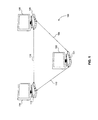
- FIG. 1 depicts an exemplary network 100 of cable set top boxes according to one embodiment.
- Each cable set top box (101, 106, and 112) may output to one or more display devices, such as a television (102, 108, and 114).
- Cable set top boxes 100, 106, and 112 may include on-chip MoCA modules, enabling them to communicate (104, 110, and 116) with each other over existing coaxial cable infrastructure.
- a first cable set top box 101 configured to output to a television 102 in a family room may have access to internet through an Ethernet connection.
- Internet data from the first cable set top box 101 in the family room may be sent to a second cable set top box 106 configured to output to a television 108 in a master bedroom.
- MoCA subsystems in the first cable set top box 101 and the second cable set top box 106 enable the cable set top boxes to communicate 104 over coaxial cable, and data may be sent from the first cable set top box 101 to the second cable set top box 106 using the MoCA subsystems in each cable set top box.
- the second cable set top box 106 may access internet data received by the first cable set top box 101 even if the second cable set top box 106 is not directly connected to the internet. Further, for example, using MoCA functionality, the second cable set top box 106 may access television channel from the first cable set top box 101. Additionally, by using SATA subsystems on-chip in each cable set top box, stored television data from another room may be paused and/or time shifted.
- Solutions provided by various embodiments support integration of cable tuners and MoCA on the same integrated circuit in a device, such as a cable set-top box.
- This integration advantageously allows for networking, using the same cable infrastructure for both the cable tuners and MoCA functionality, and thus avoids the need for separate networks for the cable tuners and MoCA support.
- the memory interface for the system is merged into a single architecture.
- DDR Double Data Rate
- Embodiments further include a memory interface that supports concurrent operation of two subsystems: DOCSIS and the video/audio subsystem, which are explained below in further detail with reference to FIG. 2 .
- the DOCSIS and video/audio subsystems each have bandwidth and memory requirements and access on-chip DDR memory and flash memory interfaces configured to interface with off-chip DDR memory and flash memory.
- both the DOCSIS and the video/audio subsystems have security requirements. For example, if the DOCSIS and video/audio subsystems run concurrently and share the same memory (for example, DDR memory), the DDR memory may be hacked into, and video and audio content may be stolen.
- DDR memory for example, DDR memory
- the code in the DDR memory may be authenticated before it is run. Additionally, the DOCSIS subsystem may be prevented from accessing the flash interface directly -- instead, the DOCSIS may be required to use the audio/video processor in the host before it can access flash memory.
- Embodiments further provide an on-chip MoCA subsystem for networking over existing coaxial cable infrastructure.
- the MoCA subsystem is configured for autonomous operation (with respect to a host Central Processing Unit (“CPU")) by using an embedded CPU in the MoCA subsystem.
- the embedded CPU is configured to access (and run code from) memory directly through the system bus, and the embedded CPU handshakes with the main CPU of the integrated circuit.
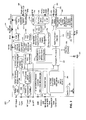
- FIG. 2 depicts an exemplary system on an integrated circuit 200 embodiment integrating a MoCA core and a cable tuner on the same integrated circuit.
- Radio Frequency (“RF") input data 202 from a television transmission is received by a direct conversion tuner 204.
- Direct conversion tuner 204 then converts a selected channel(s) of the television transmission to baseband.
- the baseband transmission is then be demodulated by the demodulator interleaver receiver 206.
- the output of the demodulator 206 is input into the DOCSIS MAC 208 for processing.
- the DOCSIS subsystem combines two 1 GHz tuners 204, two 1064-QAM receivers 206, a 256-QAM upstream transmitter 210 with integrated 2 GHz power DACs 212, a Quadrature Phase-shift Keying ("QPSK") to 256-QAM advanced TDMA and SCDMA modulator 213, an Ethernet MAC/PHY 214, a DOCSIS MAC 208, and a dual-thread MIPS232 processor 216.
- QPSK Quadrature Phase-shift Keying
- the integrated tuners 204 receive RF signals from external Low Noise Amplifiers (LNAs) in the 54-1002 MHz range and directly convert one or more channels to baseband signals.
- LNAs Low Noise Amplifiers
- the internal Analog Front End (“AFE") and receivers 206 sample and demodulate the signal with recovered clock and carrier timing, filter and equalize the data and pass soft decisions to an Forward Error Correction (“FEC”) decoder.
- FEC Forward Error Correction
- the upstream transmitter 210 takes burst or continuous data, provides FEC encoding and pre-equalization, filters and modulates the data stream, and provides a direct 0 ⁇ 108 MHz analog output with output power control to the headend.
- an out-of-band (“OOB”) receiver 209 receives a signal from the tuner, digitizes a Surface Acoustic Wave (“SAW”) centered intermediate frequency, demodulates the signal with recovered clock and carrier timing, filters and equalizes the data, and incorporates a DigiCipher II/DAVIC compatible FEC decoder 211.
- a Pulse-code Modulation ("PCM”) Highway Interface 218 is also included for interfacing to external voice Codec devices.
- a transport packet is sent from the demodulator 206 to the transport processor 220.
- the transport processor 220 processes the transport packet and removes any encryption.
- the system also includes a security processor 222 for providing secure boot key generation, management, and protection, and the security processor also assists in the processing of the transport packet.
- the Data Transport Processor is an MPEG-2 DVB-compliant transport stream message / Packetized Elementary Stream (“PES”) parser and demultiplexer capable of simultaneously processing 255 Proportional-integral-derivatives (“PIDs”) via 255 PID channels in up to six independent transport stream inputs (selected from four external inputs and three internal inputs), and two internal playback channels.
- PIDs Proportional-integral-derivatives
- the data transport supports decryption for up to 255 PID channels in all streams, and all 255 PID channels are used by the Record, Audio, and Video Interface Engine (RAVE), processors, message filter, as well as for output via the dual remux module 223.
- RAVE Record, Audio, and Video Interface Engine
- the data transport module RAVE supports 24 contexts, and each RAVE context is configured as either a record context for PVR functionality or as an AudioNideo ("AV") context to interface to audio and video decoders.
- the transport additionally provides 1DES/3DES/DVB/Multi2/AES descrambling support.
- a memory-to-memory DMA security module is programmed for supporting AES/1DES/3DES/CSS/CPRM/CPPM/DTCP copy protection algorithms/standards.
- the output data from the transport processor 220 is stored in memory (for example, DDR memory 224).
- a video decoder 226 retrieves this data from memory 224 and decode the data, and the data is further processed and enhanced by a deinterlacer and scalers 228 to improve data quality.
- the processed and enhanced video data is also be stored in memory 224 for later display.
- the video decoder 226 is be capable of supporting high-definition AVC, VC-1, and Advanced Television Systems Committee (“ATSC”) MPEG-2 streams.
- the video decoder 226 also supports high-definition VC-1 (Advanced Profile Level 3, Main, and Simple Profiles) and ATSC compliant MPEG-2, Main Profile at Main and High Levels.
- the CPU communicates 225 with the Host Controllers (HC) through the HC's operational registers and through data structures residing in shared system memory.
- the host CPU is responsible for putting the data into external Dynamic Random Access Memory ("DRAM") from wherever the data is really being sourced (i.e., hard drive, Internet, transport memory buffer, etc.). Once the data has been put into external DRAM, a playback module is enabled to read the data from external DRAM and deliver it to RAVE, message, and/or remux modules.
- DRAM Dynamic Random Access Memory
- any graphics or additional video are combined just before being displayed, and the manipulated video are then sent to a video encoder(s) 230 for display, either through analog DAC outputs or through the High-Definition Multimedia Interface ("HDMI") interface.
- the system includes a dual-stream analog video encoder 230 that supports Macrovision®1 and DCS Macrovision® and the following output standards: NTSC-M, NTSC-J, PAL-BDGHIN, PAL-M, PAL-Nc, and SECAM.
- the following output formats are additionally supported: composite, S-video, SCART1, SCART2, RGB and YPrPb component, and the system supports output resolutions of 480i, 480p, 576i, 576p, 720p, 1080i, and 1080p.
- six output DACs 232 are available to be shared amongst the output functions.
- the system also supports output over an HDMI interface 234. High quality video and graphics processing are integrated 234 into the integrated circuit, featuring advanced studio quality 2D/3D graphics processing while still maintaining efficient use of memory bandwidth.
- Transport streams come through the transport processor 220, which parse the transport streams to extract and, if necessary, decrypt elementary audio and video streams.
- Transport streams are stored directly into memory 224 for immediate display, or transport streams are routed to a storage interface such as SATA 236 for future use or for trick play and time shifting.
- Transport streams are also routed to a network interface such as Ethernet for home media-networking purposes (in-house distribution of content) and may also be sent over a transport remux output interface (serial).
- Audio data is received from the transport processor 220 and processed by an audio processor and decoder 238.
- the audio processor and decoder 238 is capable of decoding a broad range of formats including Dolby Digital, Dolby Digital Plus, AAC 5.1, AAC+ Level 2, AAC+ Level 4, WMA, and MPEG 1 Layer 1, 2, and 3 with simultaneous pass-through support. 3D SRS® Audio is also supported.
- the audio processor also supports advanced transcoding to DTS and includes audio DACs 239, and available audio outputs include an SPDIF 240 and analog outputs 242.
- motion adaptive de-interlacing with 3:2 pull-down and Letterbox Detection are included.
- Digital Noise Reduction support is also included to reduce mosquito noise and MPEG artifacts, including block noise, and digital contour removal is also supported for low bit rate AVC streams.
- Embodiments incorporate a complete MIPS 4380 class microprocessor subsystem 244, including caches with bridging to memory and a local bus. NAND, parallel, and serial NOR flash are also supported.
- Integrated peripherals 246 include UARTS, two ISO7816 smart card interfaces, counter/timers, General Purpose Input/Output (“GPIO”), keypad/LED controller, IR receivers, IR blaster, and Broadcom Serial Control (“BSC”) and Serial Peripheral Interface (“SPI”) controllers.
- Advanced connectivity features include two USB 2.0 ports 247 and Media Independent Interface (MII) capable of operating at 50 MHz or a Multimedia over Cable Alliance (MoCA) interface.
- MII Media Independent Interface
- MoCA Multimedia over Cable Alliance
- a single port SATA interface 248 is also provided for PVR.
- Dynamic Power Management is implemented to support increasing power environment requirements including (among other sources) those from ENERGY STAR, The European Commission, Institute for Environment and Sustainability and the National Resources Defense Council (NRDC).
- three power modes are implemented consistent with these specifications: (1) Passive Standby; (2) Active Standby; and (3) Active.
- Passive Standby Mode is a lowest power mode, wherein a product is connected to power, but wherein there is no active functionality.
- a device operating under Passive Standby mode may be "awakened” by external stimuli (or timer).
- Active Standby Mode a product may be connected to power with limited functionality that includes sending/receiving data from the front-end and/or network interfaces.
- a device operating under Active Standby Mode may be awakened by external stimuli (or timer) and/or in response to certain network data. Under Active Mode, full functionality is provided to a connected product.
- a Dynamic Power Management block controls Power Management transitions and is specifically designed so that Power Management and/or Power Management transitions do not introduce security vulnerabilities.
- An embodiment may further include a MoCA subsystem 250.
- the MoCA subsystem includes a PHY, MAC, and Network Interface.
- the MoCA module includes a fully embedded baseband processor and combines digital, analog, and RF elements.
- the embedded MIPS CPU implement the MoCA protocol, freeing the integrated circuit's primary processor from responsibility for MoCA link maintenance.
- the analog module includes a dual 11-bit ADC @ 200 MHz, a dual 1-bit DAC 2 400 MHz, and an embedded PLL, and the RF portion includes a tuner module along with separate TX/RX mixers, gain amplifiers, and filters.
- Embodiments may also include an on-chip clock generator 252, a free pool generator 254, and an input 256 for streaming uncompressed PAL or NTSC Standard Definition TV signals using the TU-R Recommendation BT.656 protocol.
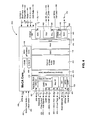
- FIG. 3 depicts an exemplary bus interface 300 that can be utilized with the various modules of the integrated circuit 200 in accordance with one embodiment.
- modules comprising the integrated circuit 200 access system memory bus 302.
- the DOCSIS subsystem 304 utilizes a separate bus, and the DOCSIS subsystem 304 accesses the system bus 302 through a bridge 306.
- the secure processor 308 and the host MIPS 310 directly accesses the flash controller 312 and the flash memory through the flash interface 314. Restricting access to the flash memory provides enhanced security.
- the host is more secure than the DOCSIS subsystem, and if the DOCSIS subsystem 304 is allowed direct access to flash memory, unauthorized users may download software through the DOCSIS interface and reach flash memory.
- the modules connected to the system memory bus include a Sundry module 316 (a peripheral module controlling interfaces external to the set-top box), a SATA interface 318, a USB 2.0 host interface 320, the transport processor 322, an audio processor 324, a graphics engine 326, a video encoder (VEC) 328 for formatting video, a Broadcom Video Network (BVN) video processor 330 (which contains scalers and works with the video encoder 328), a Motion Adapter Deinterlacer (MAD) module 332 (for recovering a stream for processing for outgoing HD), an Advanced Video Codec (AVC) module 334, and a MoCA module 336.
- Sundry module 316 a peripheral module controlling interfaces external to the set-top box
- SATA interface 318 a USB 2.0 host interface 320
- the transport processor 322 an audio processor 324
- a graphics engine 326 for formatting video
- VEC video encoder
- BBN Broadcom Video Network
- MBD Motion Adapter Deinterlacer
- AVC Advanced
- FIG. 4 depicts a block diagram of a MoCA subsystem 250 in accordance with one embodiment.
- the MoCA subsystem 250 consists of a MoCA PHY processor (PHY) 406 (which include a digital baseband PHY and an Analog Front End (AFE) 408 associated with Analog/RF block 402), a MoCA packet processor (MAC) 410, an Ethernet convergence layer (ECL) 414, an interface block 415, and an embedded CPU 416 and subsystem enabling the autonomous operation of a MoCA port in a system.
- the embedded CPU 416 is configured to access (and run code from) memory 224 directly through the system bus 302, and the embedded CPU handshakes with the main CPU of the integrated circuit. This functionality allows the MoCA subsystem to act autonomously with respect to the CPU of the integrated circuit.
- Analog interface 402 includes an analog to digital converter (ADC) 404.
- the PHY 406 is configured to receive 411 the digital signals from the MAC 410 and convert them to analog (using a digital to analog converter (DAC) 405) for transmission 412.
- the transmitter 452 receives frame data and control signals from the MAC layer and prepare them to be transmitted on the coax line.
- the transmitter 452 is configured to transmit signals RF-Clck 454 and RF_Data 456. Both the transmitter 452 and the DAC 405 receives clock signals (458 and 460) from a reference clock 462.
- the MoCA subsystem receives data and control messages encapsulated in Ethernet packets via the Gigabit Media Independent Interface (G/MII) 418 and a data and control interface 419.
- the G/MII interface 418 is used for MoCA or as a generic G/MII interface, and the G/MII interface 418 is configured to interface with an external Ethernet block 214.
- the MoCA subsystem is managed by an external host via MoCA Management Protocol (MMP), using Management Data Input/Output (“MDIO”) signals input into Management Data Clock / Management Data Input/Output Interface MDC/MDIO 438.
- MMP MoCA Management Protocol
- MDIO Management Data Input/Output
- An Ethernet Convergence Layer (“ECL”) 414 classifies incoming Ethernet frames based on their MAC and/or 802.1Q tag and map the Ethernet packets to the appropriate MoCA destination node.
- the ECL 414 also handles Unicast, Multicast and Broadcast transmissions.
- a side signal enables bypassing the ECL 414 classifier with a classifying signal that arrives directly from the external host through host interface 420.
- the classified Ethernet frames are stored in their associated queues in the internal data buffers 412.
- the ECL 414 converts MoCA data to Ethernet format before the data is sent to the G/MII 418. Data sent from the G/MII 418 goes to an Ethernet MAC before it reaches the system memory bus 302.
- the MAC 410 is configured to handle the following: MoCA network management including initialization, admission control, link management, topology management and privacy management; network scheduling including Reservation Request and Media Access Plan (MAP); and packet processing as specified in the MoCA 1.0 and 1.1 Specifications.
- MoCA network management including initialization, admission control, link management, topology management and privacy management
- network scheduling including Reservation Request and Media Access Plan (MAP)
- packet processing as specified in the MoCA 1.0 and 1.1 Specifications.
- the MAC 410 encapsulates Ethernet packets received from the ECL 414 into MoCA frames and deliver them to the PHY 406 for transmission over coaxial cable.
- the MAC decapsulates the Ethernet frames from the MoCA frames received from the PHY and transfer them over the G/MII interface 418.
- the PHY 406 performs the physical transmission and reception of data packets according to MoCA 1.0 Specifications.
- the MoCA subsystem When the G/MII interface 418 is exported, the MoCA subsystem appears as an Ethernet PHY to an external MAC.
- the MoCA Core G/MII interface is full duplex and supports IEEE 802.x Flow Control 434 causing data transfer to pause 436 when the MoCA Core can not receive new packets.
- the host interface 420 includes a serial peripheral interface (SPI) for general configuration, a generic interface for message passing and boot (G-Bus Host) 422, and a generic interface for code paging via DMA (G-Bus page) 424.
- the interface block further includes interfaces for host interrupts 426, general purpose input and output 428, and a serial interface for debugging (UART- Universal Asynchronous Receiver/Transmitter) 430.
- the MoCA subsystem supports a Stand Alone Mode 432. In this mode, the MoCA subsystem will act as a MoCA modem, and the MoCA G/MII 418 connects directly to a G/MII port on an integrated circuit.
- the MoCA subsystem may additionally be configured to work as an Ethernet interface, which removes the need for an additional Ethernet MAC on-chip, allowing for a more efficient design.
- the MoCA subsystem connects to an APB bus 438 used to configure the memory to memory DMA dedicated for the MoCA.
- the MoCA subsystem may also be configured to send diagnostic 442 signals and to receive signals through CPU debug (EJTAG) and trace (iflowTrace) interfaces 440.
- the MoCA subsystem may also include inputs for reset 444, clock in 446, clock ratio 448, and boot select 450 signals, and on-chip I-RAM 452 and D-RAM 454 may be included.
- the above system and process may be implemented as a computer program executing on a machine, as a computer program product, or as a computer-readable medium.
Abstract
Description
- This application claims the benefit of
U.S. Provisional Application Number 61/302,817, filed February 9, 2010 - The present invention generally relates to cable set top box systems and specifically to a high definition cable set top box system with an integrated cable tuner and MoCA subsystem.
- Cable set top boxes are commonly used to receive and decode digital television broadcasts and to interface with the internet through the user's television.
- Previous cable set-top box implementations do not have integrated tuners. For home-networking, prior cable set-top box implementations use Ethernet or an external MoCA system.
- What is needed is a cable set top box system with an integrated cable tuner and a MoCA subsystem.
- According to an aspect of the invention, a system is provided on an integrated circuit, comprising:
- a cable tuner integrated on a substrate; and
- a Multimedia Over Coax Alliance (MoCA) subsystem integrated on the substrate,
- Advantageously, the MoCA subsystem is configured to operate autonomously, with respect to a host processor, via an embedded processor in the MoCA subsystem.
- Advantageously, the system further comprises a memory interface shared by a Data Over Cable Service Interface Specification (DOCSIS) subsystem and a video/audio subsystem.
- Advantageously, the integrated circuit is embedded in a cable set top box, and wherein the network is a home network.
- According to a further aspect, a system on an integrated circuit comprises:
- a cable tuner integrated on a substrate;
- a Multimedia Over Coax Alliance (MoCA) subsystem integrated on the substrate;
- a Data Over Cable Service Interface Specification (DOCSIS) subsystem integrated on the substrate; and
- a video/audio subsystem integrated on the substrate,
- Advantageously, the memory is a DDR memory, and wherein code in the DDR memory is authenticated before the code is run.
- Advantageously, the shared memory is a flash memory.
- Advantageously, the DOCSIS subsystem is prevented from accessing the flash memory directly.
- Advantageously, the DOCSIS is configured to use an audio/video processor of a host prior to accessing the flash memory.
- Advantageously, the DDR memory stores video and audio data.
- Advantageously, the flash memory is only directly accessible by a secure processor and a host Microprocessor without Interlocked Pipeline Stages (MIPS) architecture.
- Advantageously, the MoCA subsystem is configured to operate independently, with respect to a host processor, via an embedded processor in the MoCA subsystem.
- Advantageously, the MoCA includes:
- a PHY,
- a MAC,
- a network interface, and
- a baseband processor, wherein the baseband processor is configured to combine digital, analog, and RF signals.
- Advantageously, the system further comprises a transport processor configured to:
- receive transport packets from a tuner, and
- output data to a video decoder and an audio decoder.
- Advantageously, the system further comprises a SATA subsystem.
- According to an aspect, a system comprises:
- a first cable set top box including a first cable tuner and a first MoCA subsystem integrated on a first integrated circuit in the first cable set top box; and
- a second cable set top box including a second cable tuner and a second MoCA subsystem integrated on a second integrated circuit in the second cable set top box,
- Advantageously, the LAN is a home network.
- Advantageously, the first cable set top box is configured to receive internet data, and wherein the first cable set top box is configured to send the internet data via the first MoCA subsystem to the second cable set top box.
- Advantageously, the first cable set top box is configured to receive television data, and wherein the first cable set top box is configured to send the television data via the first MoCA subsystem to the second cable set top box.
- Advantageously, the second cable set top box is configured to store the television data via a SATA subsystem in the second cable set top box.
- The accompanying drawings, which are incorporated in and constitute part of the specification, illustrate embodiments of the invention and, together with the general description given above and the detailed descriptions of embodiments given below, serve to explain the principles of the present invention. In the drawings:
-
FIG. 1 depicts an exemplary network of cable set top boxes according to one embodiment. -
FIG. 2 depicts an exemplary system on an integrated circuit embodiment integrating a MoCA core and a cable tuner on the same integrated circuit. -
FIG. 3 depicts an exemplary bus interface in accordance with one embodiment. -
FIG. 4 depicts a block diagram of a MoCA core in accordance with one embodiment. - Features and advantages of the present invention will become more apparent from the detailed description set forth below when taken in conjunction with the drawings, in which like reference characters identify corresponding elements throughout. In the drawings, like reference numbers generally indicate identical, functionally similar, and/or structurally similar elements. The drawing in which an element first appears is indicated by the leftmost digit(s) in the corresponding reference number.
- A high-definition cable set-top box system on an integrated circuit with integrated tuners and support for the Multimedia Over Coax Alliance (MoCA) standard is provided. By integrating cable tuners into a single integrated circuit (chip), board space is reduced, allowing for a smaller form-factor cable set-top box. MoCA integration also helps reduce cable set-top box form factor and additionally allows for home networking on the same cable network in the house without requiring a separate network such as Ethernet or USB. The system may include a memory interface shared by Data Over Cable Service Interface Specification ("DOCSIS") and video/audio subsystems. The system may further include an embedded processor in the MoCA subsystem, enabling autonomous operation of the MoCA subsystem and secure flash memory that is not directly accessible by the DOCSIS subsystem.
- Embodiments of the system may be implemented on a single integrated circuit, reducing board space, allowing for smaller form factor cable set-top box, and allowing for home networking on the same cable network in the home without requiring a separate network for MoCA support, such as Ethernet or Universal Serial Bus ("USB"). Advantageously, solutions provided by embodiments disclosed herein allow for MoCA support using existing coaxial cable lines. Further, the memory interface may be merged into a single architecture shared by both the front end and the back end of the integrated circuit and designed to meet the requirements of both the front end and the back end, including security requirements.
- In an embodiment, a cable set-top box solution is provided offering integrated Advanced Video Coding ("AVC") (H.264/MPEG-4 Part 10), Moving Picture Experts Group ("MPEG"), MPEG-4
Part 2, MPEG-2, and SMPTE 421M video codec standard ("VC-1") video decoding technology. DivX, H.264, Audio Video Standard ("AVS"), and XviD formats may also be supported. - In an embodiment, a Data Over Cable Service Interface Specification (DOCSIS) subsystem is also provided to support transfer of cable television data. The DOCSIS subsystem integrates dual tuners. Additionally, the DOCSIS subsystem provides two integrated downstream demodulators supporting up to 1024 Quadrature Amplitude Modulation ("QAM"), an Out-of-band ("OOB") demodulator, an upstream modulator supporting rate up to 256 QAM, a DOCSIS 3.0 MAC capable of bonding up to four channels, a transmission convergence module supporting mapping for both Synchronous Code Division Multiple Access ("SCDMA") and Advanced Time Division Multiple Access ("ATDMA"), and a dual-thread MIPS32 processor core with 800 DMIPS rating.
- In an embodiment, the video/audio subsystem includes a data transport processor, a high-definition advanced video decoder, an advanced audio decoder, a 2d/3D graphics engine, motion adaptive de-interlacing, high quality video processing hardware, six video Digital to Analog Converters ("DACs"), and stereo high-fidelity audio DACs. The video/audio subsystem may be managed by a
MIPS 4380 class processor with a Floating Point Unit ("FPU"). Additionally, the video decoder may be designed to output up to a 1080p60 (1,080 lines of vertical resolution and 30 progressive scan frames per second) output format. - In an embodiment, various interfaces are added to support all required set-top box functions such as Infrared ("IR") remote, Light-emitting Diode ("LED"), Keypads, Universal Asynchronous Receiver / Transmitter ("UARTs"), Inter-Integrated Circuit ("I2C"), and System Packet Interface ("SPI"). A Serial Advanced Technology Attachment ("SATA") interface may be included to support Personal Video Recorder ("PVR") capability, and two USB 2.0 ports may also be provided. A 10/100 Ethernet Physcial ("PHY") Layer / Media Access Control ("MAC") Layer may be integrated for home networking, and a MoCA module with tuner, receiver, and DAC may also be integrated into the system.
- The Multimedia Over Coax Alliance (MoCA) standard supports networking (for example, home networking) over existing coaxial cable infrastructure. Devices, such as cable set top boxes, incorporating MoCA functionality can communicate over coaxial cable with other devices connected to a network.
-
FIG. 1 depicts anexemplary network 100 of cable set top boxes according to one embodiment. Each cable set top box (101, 106, and 112) may output to one or more display devices, such as a television (102, 108, and 114). Cable settop boxes - Home networking with MoCA functionality according to various embodiments presents several advantages. For example, a first cable set
top box 101 configured to output to atelevision 102 in a family room may have access to internet through an Ethernet connection. Internet data from the first cable settop box 101 in the family room may be sent to a second cable settop box 106 configured to output to atelevision 108 in a master bedroom. MoCA subsystems in the first cable settop box 101 and the second cable settop box 106 enable the cable set top boxes to communicate 104 over coaxial cable, and data may be sent from the first cable settop box 101 to the second cable settop box 106 using the MoCA subsystems in each cable set top box. For example, using this functionality, the second cable settop box 106 may access internet data received by the first cable settop box 101 even if the second cable settop box 106 is not directly connected to the internet. Further, for example, using MoCA functionality, the second cable settop box 106 may access television channel from the first cable settop box 101. Additionally, by using SATA subsystems on-chip in each cable set top box, stored television data from another room may be paused and/or time shifted. - Solutions provided by various embodiments support integration of cable tuners and MoCA on the same integrated circuit in a device, such as a cable set-top box. This integration advantageously allows for networking, using the same cable infrastructure for both the cable tuners and MoCA functionality, and thus avoids the need for separate networks for the cable tuners and MoCA support.
- In an embodiment, the memory interface for the system is merged into a single architecture. For example, only one Double Data Rate ("DDR") memory is shared by a front end and a back end of a system according to an embodiment. Embodiments further include a memory interface that supports concurrent operation of two subsystems: DOCSIS and the video/audio subsystem, which are explained below in further detail with reference to
FIG. 2 . The DOCSIS and video/audio subsystems each have bandwidth and memory requirements and access on-chip DDR memory and flash memory interfaces configured to interface with off-chip DDR memory and flash memory. - Additionally, both the DOCSIS and the video/audio subsystems have security requirements. For example, if the DOCSIS and video/audio subsystems run concurrently and share the same memory (for example, DDR memory), the DDR memory may be hacked into, and video and audio content may be stolen.
- To address these concerns, all of the code in the DDR memory may be authenticated before it is run. Additionally, the DOCSIS subsystem may be prevented from accessing the flash interface directly -- instead, the DOCSIS may be required to use the audio/video processor in the host before it can access flash memory.
- Embodiments further provide an on-chip MoCA subsystem for networking over existing coaxial cable infrastructure. In an embodiment, the MoCA subsystem is configured for autonomous operation (with respect to a host Central Processing Unit ("CPU")) by using an embedded CPU in the MoCA subsystem. For example, the embedded CPU is configured to access (and run code from) memory directly through the system bus, and the embedded CPU handshakes with the main CPU of the integrated circuit.
-
FIG. 2 depicts an exemplary system on anintegrated circuit 200 embodiment integrating a MoCA core and a cable tuner on the same integrated circuit. Radio Frequency ("RF")input data 202 from a television transmission is received by adirect conversion tuner 204.Direct conversion tuner 204 then converts a selected channel(s) of the television transmission to baseband. The baseband transmission is then be demodulated by thedemodulator interleaver receiver 206. - If the system is being used for internet access, the output of the
demodulator 206 is input into theDOCSIS MAC 208 for processing. In an embodiment, the DOCSIS subsystem combines two 1GHz tuners 204, two 1064-QAM receivers 206, a 256-QAMupstream transmitter 210 with integrated 2GHz power DACs 212, a Quadrature Phase-shift Keying ("QPSK") to 256-QAM advanced TDMA andSCDMA modulator 213, an Ethernet MAC/PHY 214, aDOCSIS MAC 208, and a dual-thread MIPS232 processor 216. - The
integrated tuners 204 receive RF signals from external Low Noise Amplifiers (LNAs) in the 54-1002 MHz range and directly convert one or more channels to baseband signals. The internal Analog Front End ("AFE") andreceivers 206 sample and demodulate the signal with recovered clock and carrier timing, filter and equalize the data and pass soft decisions to an Forward Error Correction ("FEC") decoder. Theupstream transmitter 210 takes burst or continuous data, provides FEC encoding and pre-equalization, filters and modulates the data stream, and provides a direct 0―108 MHz analog output with output power control to the headend. - In an embodiment, an out-of-band ("OOB")
receiver 209 receives a signal from the tuner, digitizes a Surface Acoustic Wave ("SAW") centered intermediate frequency, demodulates the signal with recovered clock and carrier timing, filters and equalizes the data, and incorporates a DigiCipher II/DAVICcompatible FEC decoder 211. A Pulse-code Modulation ("PCM")Highway Interface 218 is also included for interfacing to external voice Codec devices. - If the system is being used for cable modem functionality, a transport packet is sent from the
demodulator 206 to thetransport processor 220. Thetransport processor 220 processes the transport packet and removes any encryption. The system also includes asecurity processor 222 for providing secure boot key generation, management, and protection, and the security processor also assists in the processing of the transport packet. In an embodiment, the Data Transport Processor is an MPEG-2 DVB-compliant transport stream message / Packetized Elementary Stream ("PES") parser and demultiplexer capable of simultaneously processing 255 Proportional-integral-derivatives ("PIDs") via 255 PID channels in up to six independent transport stream inputs (selected from four external inputs and three internal inputs), and two internal playback channels. In an embodiment, the data transport supports decryption for up to 255 PID channels in all streams, and all 255 PID channels are used by the Record, Audio, and Video Interface Engine (RAVE), processors, message filter, as well as for output via thedual remux module 223. The data transport module RAVE supports 24 contexts, and each RAVE context is configured as either a record context for PVR functionality or as an AudioNideo ("AV") context to interface to audio and video decoders. The transport additionally provides 1DES/3DES/DVB/Multi2/AES descrambling support. A memory-to-memory DMA security module is programmed for supporting AES/1DES/3DES/CSS/CPRM/CPPM/DTCP copy protection algorithms/standards. - In an embodiment, the output data from the
transport processor 220 is stored in memory (for example, DDR memory 224). Avideo decoder 226 retrieves this data frommemory 224 and decode the data, and the data is further processed and enhanced by a deinterlacer andscalers 228 to improve data quality. The processed and enhanced video data is also be stored inmemory 224 for later display. In an embodiment, thevideo decoder 226 is be capable of supporting high-definition AVC, VC-1, and Advanced Television Systems Committee ("ATSC") MPEG-2 streams. Thevideo decoder 226 also supports high-definition VC-1 (Advanced Profile Level 3, Main, and Simple Profiles) and ATSC compliant MPEG-2, Main Profile at Main and High Levels. - In an embodiment, the CPU communicates 225 with the Host Controllers (HC) through the HC's operational registers and through data structures residing in shared system memory. In an embodiment, the host CPU is responsible for putting the data into external Dynamic Random Access Memory ("DRAM") from wherever the data is really being sourced (i.e., hard drive, Internet, transport memory buffer, etc.). Once the data has been put into external DRAM, a playback module is enabled to read the data from external DRAM and deliver it to RAVE, message, and/or remux modules.
- During video processing, any graphics or additional video are combined just before being displayed, and the manipulated video are then sent to a video encoder(s) 230 for display, either through analog DAC outputs or through the High-Definition Multimedia Interface ("HDMI") interface. In an embodiment, the system includes a dual-stream
analog video encoder 230 that supportsMacrovision® 1 and DCS Macrovision® and the following output standards: NTSC-M, NTSC-J, PAL-BDGHIN, PAL-M, PAL-Nc, and SECAM. In an embodiment, the following output formats are additionally supported: composite, S-video, SCART1, SCART2, RGB and YPrPb component, and the system supports output resolutions of 480i, 480p, 576i, 576p, 720p, 1080i, and 1080p. In an embodiment, sixoutput DACs 232 are available to be shared amongst the output functions. The system also supports output over anHDMI interface 234. High quality video and graphics processing are integrated 234 into the integrated circuit, featuring advanced studio quality 2D/3D graphics processing while still maintaining efficient use of memory bandwidth. - Compressed video data enters the device in the form of MPEG transport streams. Transport streams come through the
transport processor 220, which parse the transport streams to extract and, if necessary, decrypt elementary audio and video streams. Transport streams are stored directly intomemory 224 for immediate display, or transport streams are routed to a storage interface such asSATA 236 for future use or for trick play and time shifting. Transport streams are also routed to a network interface such as Ethernet for home media-networking purposes (in-house distribution of content) and may also be sent over a transport remux output interface (serial). - Audio data is received from the
transport processor 220 and processed by an audio processor anddecoder 238. In an embodiment, the audio processor anddecoder 238 is capable of decoding a broad range of formats including Dolby Digital, Dolby Digital Plus, AAC 5.1,AAC+ Level 2, AAC+ Level 4, WMA, andMPEG 1Layer audio DACs 239, and available audio outputs include anSPDIF 240 and analog outputs 242. - In an embodiment, motion adaptive de-interlacing with 3:2 pull-down and Letterbox Detection are included. Digital Noise Reduction support is also included to reduce mosquito noise and MPEG artifacts, including block noise, and digital contour removal is also supported for low bit rate AVC streams.
- Embodiments incorporate a
complete MIPS 4380class microprocessor subsystem 244, including caches with bridging to memory and a local bus. NAND, parallel, and serial NOR flash are also supported. -
Integrated peripherals 246 include UARTS, two ISO7816 smart card interfaces, counter/timers, General Purpose Input/Output ("GPIO"), keypad/LED controller, IR receivers, IR blaster, and Broadcom Serial Control ("BSC") and Serial Peripheral Interface ("SPI") controllers. Advanced connectivity features include two USB 2.0ports 247 and Media Independent Interface (MII) capable of operating at 50 MHz or a Multimedia over Cable Alliance (MoCA) interface. A singleport SATA interface 248 is also provided for PVR. - In an embodiment, Dynamic Power Management is implemented to support increasing power environment requirements including (among other sources) those from ENERGY STAR, The European Commission, Institute for Environment and Sustainability and the National Resources Defense Council (NRDC). In an embodiment, three power modes are implemented consistent with these specifications: (1) Passive Standby; (2) Active Standby; and (3) Active. Passive Standby Mode is a lowest power mode, wherein a product is connected to power, but wherein there is no active functionality. A device operating under Passive Standby mode may be "awakened" by external stimuli (or timer). In Active Standby Mode, a product may be connected to power with limited functionality that includes sending/receiving data from the front-end and/or network interfaces. A device operating under Active Standby Mode may be awakened by external stimuli (or timer) and/or in response to certain network data. Under Active Mode, full functionality is provided to a connected product. A Dynamic Power Management block controls Power Management transitions and is specifically designed so that Power Management and/or Power Management transitions do not introduce security vulnerabilities.
- An embodiment may further include a
MoCA subsystem 250. In an embodiment, the MoCA subsystem includes a PHY, MAC, and Network Interface. The MoCA module includes a fully embedded baseband processor and combines digital, analog, and RF elements. The embedded MIPS CPU implement the MoCA protocol, freeing the integrated circuit's primary processor from responsibility for MoCA link maintenance. The analog module includes a dual 11-bit ADC @ 200 MHz, a dual 1-bit DAC 2 400 MHz, and an embedded PLL, and the RF portion includes a tuner module along with separate TX/RX mixers, gain amplifiers, and filters. - Embodiments may also include an on-
chip clock generator 252, afree pool generator 254, and aninput 256 for streaming uncompressed PAL or NTSC Standard Definition TV signals using the TU-R Recommendation BT.656 protocol. -
FIG. 3 depicts anexemplary bus interface 300 that can be utilized with the various modules of theintegrated circuit 200 in accordance with one embodiment. In an embodiment, modules comprising theintegrated circuit 200 accesssystem memory bus 302. In an embodiment, theDOCSIS subsystem 304 utilizes a separate bus, and theDOCSIS subsystem 304 accesses thesystem bus 302 through abridge 306. - In an embodiment, only the
secure processor 308 and thehost MIPS 310 directly accesses theflash controller 312 and the flash memory through theflash interface 314. Restricting access to the flash memory provides enhanced security. In an embodiment, the host is more secure than the DOCSIS subsystem, and if theDOCSIS subsystem 304 is allowed direct access to flash memory, unauthorized users may download software through the DOCSIS interface and reach flash memory. - In an embodiment, the modules connected to the system memory bus include a Sundry module 316 (a peripheral module controlling interfaces external to the set-top box), a
SATA interface 318, a USB 2.0host interface 320, thetransport processor 322, anaudio processor 324, agraphics engine 326, a video encoder (VEC) 328 for formatting video, a Broadcom Video Network (BVN) video processor 330 (which contains scalers and works with the video encoder 328), a Motion Adapter Deinterlacer (MAD) module 332 (for recovering a stream for processing for outgoing HD), an Advanced Video Codec (AVC)module 334, and aMoCA module 336. -
FIG. 4 depicts a block diagram of aMoCA subsystem 250 in accordance with one embodiment. In an embodiment, theMoCA subsystem 250 consists of a MoCA PHY processor (PHY) 406 (which include a digital baseband PHY and an Analog Front End (AFE) 408 associated with Analog/RF block 402), a MoCA packet processor (MAC) 410, an Ethernet convergence layer (ECL) 414, aninterface block 415, and an embeddedCPU 416 and subsystem enabling the autonomous operation of a MoCA port in a system. The embeddedCPU 416 is configured to access (and run code from)memory 224 directly through thesystem bus 302, and the embedded CPU handshakes with the main CPU of the integrated circuit. This functionality allows the MoCA subsystem to act autonomously with respect to the CPU of the integrated circuit. -
Analog interface 402 includes an analog to digital converter (ADC) 404. In an embodiment, thePHY 406 is configured to receive 411 the digital signals from theMAC 410 and convert them to analog (using a digital to analog converter (DAC) 405) fortransmission 412. Thetransmitter 452 receives frame data and control signals from the MAC layer and prepare them to be transmitted on the coax line. Thetransmitter 452 is configured to transmit signals RF-Clck 454 andRF_Data 456. Both thetransmitter 452 and theDAC 405 receives clock signals (458 and 460) from areference clock 462. - In an embodiment, the MoCA subsystem receives data and control messages encapsulated in Ethernet packets via the Gigabit Media Independent Interface (G/MII) 418 and a data and
control interface 419. The G/MII interface 418 is used for MoCA or as a generic G/MII interface, and the G/MII interface 418 is configured to interface with anexternal Ethernet block 214. The MoCA subsystem is managed by an external host via MoCA Management Protocol (MMP), using Management Data Input/Output ("MDIO") signals input into Management Data Clock / Management Data Input/Output Interface MDC/MDIO 438. - An Ethernet Convergence Layer ("ECL") 414 classifies incoming Ethernet frames based on their MAC and/or 802.1Q tag and map the Ethernet packets to the appropriate MoCA destination node. The
ECL 414 also handles Unicast, Multicast and Broadcast transmissions. A side signal enables bypassing theECL 414 classifier with a classifying signal that arrives directly from the external host throughhost interface 420. The classified Ethernet frames are stored in their associated queues in the internal data buffers 412. In an embodiment, theECL 414 converts MoCA data to Ethernet format before the data is sent to the G/MII 418. Data sent from the G/MII 418 goes to an Ethernet MAC before it reaches thesystem memory bus 302. - In an embodiment, the
MAC 410 is configured to handle the following: MoCA network management including initialization, admission control, link management, topology management and privacy management; network scheduling including Reservation Request and Media Access Plan (MAP); and packet processing as specified in the MoCA 1.0 and 1.1 Specifications. TheMAC 410 encapsulates Ethernet packets received from theECL 414 into MoCA frames and deliver them to thePHY 406 for transmission over coaxial cable. On the opposite path, the MAC decapsulates the Ethernet frames from the MoCA frames received from the PHY and transfer them over the G/MII interface 418. ThePHY 406 performs the physical transmission and reception of data packets according to MoCA 1.0 Specifications. - When the G/
MII interface 418 is exported, the MoCA subsystem appears as an Ethernet PHY to an external MAC. In an embodiment, the MoCA Core G/MII interface is full duplex and supports IEEE 802.xFlow Control 434 causing data transfer to pause 436 when the MoCA Core can not receive new packets. - The
host interface 420 includes a serial peripheral interface (SPI) for general configuration, a generic interface for message passing and boot (G-Bus Host) 422, and a generic interface for code paging via DMA (G-Bus page) 424. The interface block further includes interfaces for host interrupts 426, general purpose input andoutput 428, and a serial interface for debugging (UART- Universal Asynchronous Receiver/Transmitter) 430. - In an embodiment, the MoCA subsystem supports a Stand
Alone Mode 432. In this mode, the MoCA subsystem will act as a MoCA modem, and the MoCA G/MII 418 connects directly to a G/MII port on an integrated circuit. The MoCA subsystem may additionally be configured to work as an Ethernet interface, which removes the need for an additional Ethernet MAC on-chip, allowing for a more efficient design. - In an embodiment, the MoCA subsystem connects to an
APB bus 438 used to configure the memory to memory DMA dedicated for the MoCA. The MoCA subsystem may also be configured to send diagnostic 442 signals and to receive signals through CPU debug (EJTAG) and trace (iflowTrace) interfaces 440. The MoCA subsystem may also include inputs forreset 444, clock in 446,clock ratio 448, and boot select 450 signals, and on-chip I-RAM 452 and D-RAM 454 may be included. - The above system and process may be implemented as a computer program executing on a machine, as a computer program product, or as a computer-readable medium.
- While various embodiments of the present invention have been described above, it should be understood that they have been presented by way of example only, and not limitation. It will be apparent to persons skilled in the relevant art that various changes in form and detail can be made therein without departing from the spirit and scope of the invention. Thus, the breadth and scope of the present invention should not be limited by any of the above-described exemplary embodiments, but should be defined only in accordance with the following claims and their equivalents.
wherein the first cable set top box is configured to communicate, through the LAN, with the second cable set top box over a coaxial cable link.
Claims (15)
- A system on an integrated circuit, comprising:a cable tuner integrated on a substrate; anda Multimedia Over Coax Alliance (MoCA) subsystem integrated on the substrate,wherein the cable tuner and the MoCA subsystem are configured to communicate with a network over a shared coaxial cable.
- The system of claim 1, wherein the MoCA subsystem is configured to operate autonomously, with respect to a host processor, via an embedded processor in the MoCA subsystem.
- The system of claim 1, further comprising a memory interface shared by a Data Over Cable Service Interface Specification (DOCSIS) subsystem and a video/audio subsystem.
- The system of claim 1, wherein the integrated circuit is embedded in a cable set top box, and wherein the network is a home network.
- A system on an integrated circuit, comprising:a cable tuner integrated on a substrate;a Multimedia Over Coax Alliance (MoCA) subsystem integrated on the substrate;a Data Over Cable Service Interface Specification (DOCSIS) subsystem integrated on the substrate; anda video/audio subsystem integrated on the substrate,wherein the DOCSIS subsystem and the video/audio subsystem are configured to access a shared memory.
- The system of claim 5, wherein the memory is a DDR memory, and wherein code in the DDR memory is authenticated before the code is run.
- The system of claim 5, wherein the shared memory is a flash memory.
- The system of claim 7, wherein the DOCSIS subsystem is prevented from accessing the flash memory directly.
- The system of claim 8, wherein the DOCSIS is configured to use an audio/video processor of a host prior to accessing the flash memory.
- The system of claim 9, wherein the DDR memory stores video and audio data.
- The system of claim 7, wherein the flash memory is only directly accessible by a secure processor and a host Microprocessor without Interlocked Pipeline Stages (MIPS) architecture.
- The system of claim 5, wherein the MoCA subsystem is configured to operate independently, with respect to a host processor, via an embedded processor in the MoCA subsystem.
- The system of claim 5, wherein the MoCA includes:a PHY,a MAC,a network interface, anda baseband processor, wherein the baseband processor is configured to combine digital, analog, and RF signals.
- The system of claim 5, further comprising a transport processor configured to:receive transport packets from a tuner, andoutput data to a video decoder and an audio decoder.
- A system comprising:a first cable set top box including a first cable tuner and a first MoCA subsystem integrated on a first integrated circuit in the first cable set top box; anda second cable set top box including a second cable tuner and a second MoCA subsystem integrated on a second integrated circuit in the second cable set top box,wherein the first cable set top box and the second cable set top box are connected to a local area network (LAN), and
wherein the first cable set top box is configured to communicate, through the LAN, with the second cable set top box over a coaxial cable link.
Applications Claiming Priority (2)
| Application Number | Priority Date | Filing Date | Title |
|---|---|---|---|
| US30281710P | 2010-02-09 | 2010-02-09 | |
| US12/829,936 US9148295B2 (en) | 2010-02-09 | 2010-07-02 | Cable set-top box with integrated cable tuner and MOCA support |
Publications (3)
| Publication Number | Publication Date |
|---|---|
| EP2355413A2 true EP2355413A2 (en) | 2011-08-10 |
| EP2355413A3 EP2355413A3 (en) | 2011-08-24 |
| EP2355413B1 EP2355413B1 (en) | 2019-07-24 |
Family
ID=43896643
Family Applications (1)
| Application Number | Title | Priority Date | Filing Date |
|---|---|---|---|
| EP11000865.3A Active EP2355413B1 (en) | 2010-02-09 | 2011-02-03 | Cable set-top box with integrated cable tuner and MOCA support |
Country Status (5)
| Country | Link |
|---|---|
| US (1) | US9148295B2 (en) |
| EP (1) | EP2355413B1 (en) |
| CN (1) | CN102149009B (en) |
| HK (1) | HK1159908A1 (en) |
| TW (1) | TWI497985B (en) |
Families Citing this family (13)
| Publication number | Priority date | Publication date | Assignee | Title |
|---|---|---|---|---|
| US8806044B2 (en) * | 2011-11-29 | 2014-08-12 | Maxlinear, Inc. | Method and system for cross-protocol time synchronization |
| US9787463B2 (en) * | 2011-10-14 | 2017-10-10 | Maxlinear, Inc. | Method and system for server-side message handling in a low-power wide area network |
| US9191461B2 (en) * | 2012-02-21 | 2015-11-17 | Entropic Communications, Inc. | Software upgrade using layer-2 management entity messaging |
| CN102595245A (en) * | 2012-03-01 | 2012-07-18 | 华为终端有限公司 | Set top box interacting method and associated set top box and system |
| US9660792B2 (en) * | 2012-06-30 | 2017-05-23 | Cable Television Laboratories, Inc. | Multi-carrier transmission |
| CN103974102A (en) * | 2013-01-30 | 2014-08-06 | 云联(北京)信息技术有限公司 | Set top box |
| US9247184B2 (en) * | 2013-06-06 | 2016-01-26 | Stmicroelectronics, Inc. | Energy saving circuits and methods for multimedia over coaxial alliance (MOCA) capable devices |
| US11729054B2 (en) * | 2014-07-15 | 2023-08-15 | Comcast Cable Communications, Llc | Reconfigurable device for processing signals |
| KR102320385B1 (en) * | 2014-09-11 | 2021-11-02 | 한국전자통신연구원 | Lower Power STB Structure and Control Technology based on Network Cooperation |
| TWI575379B (en) * | 2014-11-06 | 2017-03-21 | 智同科技股份有限公司 | Set-top box with access point and modem and control method thereof |
| CN104767910A (en) * | 2015-04-27 | 2015-07-08 | 京东方科技集团股份有限公司 | Video image stitching system and method |
| US10623814B1 (en) * | 2018-11-01 | 2020-04-14 | Harmonic, Inc. | CATV Equipment fast boot after power interruption |
| CN111464847B (en) * | 2019-12-24 | 2022-12-30 | 山东中科先进技术有限公司 | Intelligent wired digital set-top box supporting network multi-scene application |
Family Cites Families (26)
| Publication number | Priority date | Publication date | Assignee | Title |
|---|---|---|---|---|
| US5491516A (en) * | 1993-01-14 | 1996-02-13 | Rca Thomson Licensing Corporation | Field elimination apparatus for a video compression/decompression system |
| US8266657B2 (en) | 2001-03-15 | 2012-09-11 | Sling Media Inc. | Method for effectively implementing a multi-room television system |
| US6813778B1 (en) * | 1999-08-16 | 2004-11-02 | General Instruments Corporation | Method and system for downloading and managing the enablement of a list of code objects |
| US6751441B1 (en) * | 2000-10-03 | 2004-06-15 | At&T Corp. | Intra-premises wireless broadband service using lumped and distributed wireless radiation from cable source input |
| US20030095447A1 (en) * | 2001-11-20 | 2003-05-22 | Koninklijke Philips Electronics N.V. | Shared memory controller for display processor |
| US7219367B2 (en) * | 2002-09-09 | 2007-05-15 | Scientific-Atlanta, Inc. | Backup communication modes |
| US8010061B2 (en) | 2002-12-24 | 2011-08-30 | Agere Systems, Inc. | Combining multimedia signaling and wireless network signaling on a common communication medium |
| US6922739B2 (en) * | 2003-02-24 | 2005-07-26 | Broadcom Corporation | System and method for dual IDE channel servicing using single multiplexed interface having first and second channel transfer over a common bus |
| US20040194147A1 (en) | 2003-03-31 | 2004-09-30 | Jeff Craven | Broadband multi-interface media module |
| US8332653B2 (en) | 2004-10-22 | 2012-12-11 | Broadcom Corporation | Secure processing environment |
| US8347341B2 (en) | 2006-03-16 | 2013-01-01 | Time Warner Cable Inc. | Methods and apparatus for centralized content and data delivery |
| US20080134276A1 (en) * | 2006-06-30 | 2008-06-05 | Martin Orrell | Receiver and aspects thereof |
| US8848745B2 (en) * | 2006-08-17 | 2014-09-30 | Broadcom Corporation | Remote flash access |
| US20080120667A1 (en) * | 2006-11-17 | 2008-05-22 | Texas Instruments Incorporated | Hybrid mpeg/ip digital cable gateway device and architecture associated therewith |
| US20080145037A1 (en) * | 2006-12-13 | 2008-06-19 | Sony Corporation | External video recorder |
| US7882365B2 (en) * | 2006-12-22 | 2011-02-01 | Spansion Llc | Systems and methods for distinguishing between actual data and erased/blank memory with regard to encrypted data |
| US8000493B2 (en) * | 2007-03-08 | 2011-08-16 | Broadcom Corporation | Method and system for watermark embedding in a multimedia system-on-chip |
| US7817642B2 (en) * | 2007-07-03 | 2010-10-19 | Applied Micro Circuits Corporation | MoCA frame bundling and frame bursting |
| US20090059933A1 (en) * | 2007-08-28 | 2009-03-05 | Tellabs Vienna, Inc. | Validating customer in-home network connectivity using moca bridge mode |
| US20090165070A1 (en) | 2007-12-19 | 2009-06-25 | Broadcom Corporation | SYSTEMS AND METHODS FOR PROVIDING A MoCA COMPATABILITY STRATEGY |
| US8412759B2 (en) * | 2008-06-27 | 2013-04-02 | Entropic Communications, Inc. | System and method for active diplexers |
| US8898716B2 (en) * | 2008-07-28 | 2014-11-25 | Stmicroelectronics International N.V. | Method and apparatus for designing a communication mechanism between embedded cable modem and embedded set-top box |
| US9414031B2 (en) * | 2008-11-26 | 2016-08-09 | Echostar Technologies L.L.C. | Account-specific encryption key |
| KR101668852B1 (en) | 2009-01-30 | 2016-10-24 | 톰슨 라이센싱 | System and method for combined home network communications and broadcast reception in a settop box |
| US8555082B1 (en) * | 2009-04-01 | 2013-10-08 | Marvell International Ltd. | Securing external memory data |
| CN102474677B (en) * | 2009-09-09 | 2016-06-08 | 美国博通公司 | Ethernet passive optical network (EPOC) based on coaxial cable |
-
2010
- 2010-07-02 US US12/829,936 patent/US9148295B2/en active Active
-
2011
- 2011-02-03 EP EP11000865.3A patent/EP2355413B1/en active Active
- 2011-02-09 TW TW100104322A patent/TWI497985B/en active
- 2011-02-09 CN CN201110035167.8A patent/CN102149009B/en active Active
- 2011-12-27 HK HK11113950.8A patent/HK1159908A1/en not_active IP Right Cessation
Also Published As
| Publication number | Publication date |
|---|---|
| CN102149009A (en) | 2011-08-10 |
| EP2355413A3 (en) | 2011-08-24 |
| TW201216688A (en) | 2012-04-16 |
| HK1159908A1 (en) | 2012-08-03 |
| US20110197243A1 (en) | 2011-08-11 |
| CN102149009B (en) | 2015-01-21 |
| US9148295B2 (en) | 2015-09-29 |
| EP2355413B1 (en) | 2019-07-24 |
| TWI497985B (en) | 2015-08-21 |
Similar Documents
| Publication | Publication Date | Title |
|---|---|---|
| US9148295B2 (en) | Cable set-top box with integrated cable tuner and MOCA support | |
| US8270920B2 (en) | Systems and methods for receiving and transferring video information | |
| US20070294738A1 (en) | Single chip cable set-top box supporting DOCSIS set-top Gateway (DSG) protocol and high definition advanced video codec (HD AVC) decode | |
| US20080263621A1 (en) | Set top box with transcoding capabilities | |
| US8799966B2 (en) | Middleware bandwidth shifting | |
| CN106231396B (en) | A kind of set-top box of the shared processing of program resource, system and method | |
| JP2006135987A (en) | Digital broadcasting data providing apparatus and method using wireless lan, and wireless terminal device | |
| US9032453B2 (en) | Method and system for multiplexed transport interface between demodulators (DEMODs) and set-top box (STB) system-on-chips (SoCs) | |
| US20060123457A1 (en) | Universal single chip set-top box | |
| US20060271654A1 (en) | Network interface unit | |
| CN103404161A (en) | Television signal processing method and device | |
| KR20070059851A (en) | Home server and its control method for integrating settop | |
| CN101039403A (en) | Enhanced display systems with dvc connectivity | |
| US6741292B1 (en) | System and method for a baseband digital television | |
| CN212381328U (en) | Line card equipment supporting live broadcast of 4K or 8K television and application system thereof | |
| KR101069267B1 (en) | Method of controlling devices and tuner device | |
| CN112055228A (en) | Line card equipment supporting live broadcast of 4K or 8K television and application system thereof | |
| US20020087993A1 (en) | Common interface module and method related thereto | |
| CN218888576U (en) | Television mainboard and television | |
| Sakurai | Digital television receiver for ISDB | |
| Huang et al. | An embedded multifunctional media system for mobile devices in terrestrial DTV relaying | |
| JP4758615B2 (en) | Wireless AV system and wireless communication apparatus | |
| KR20080065440A (en) | Network interface unit | |
| Hulyalkar | 66.4: System‐on‐Chip for Integrated Digital Television |
Legal Events
| Date | Code | Title | Description |
|---|---|---|---|
| PUAI | Public reference made under article 153(3) epc to a published international application that has entered the european phase |
Free format text: ORIGINAL CODE: 0009012 |
|
| PUAL | Search report despatched |
Free format text: ORIGINAL CODE: 0009013 |
|
| AK | Designated contracting states |
Kind code of ref document: A2 Designated state(s): AL AT BE BG CH CY CZ DE DK EE ES FI FR GB GR HR HU IE IS IT LI LT LU LV MC MK MT NL NO PL PT RO RS SE SI SK SM TR |
|
| AX | Request for extension of the european patent |
Extension state: BA ME |
|
| AK | Designated contracting states |
Kind code of ref document: A3 Designated state(s): AL AT BE BG CH CY CZ DE DK EE ES FI FR GB GR HR HU IE IS IT LI LT LU LV MC MK MT NL NO PL PT RO RS SE SI SK SM TR |
|
| AX | Request for extension of the european patent |
Extension state: BA ME |
|
| RIC1 | Information provided on ipc code assigned before grant |
Ipc: H04L 12/28 20060101AFI20110718BHEP Ipc: H04N 5/00 20110101ALI20110718BHEP |
|
| 17P | Request for examination filed |
Effective date: 20120224 |
|
| 17Q | First examination report despatched |
Effective date: 20130321 |
|
| STAA | Information on the status of an ep patent application or granted ep patent |
Free format text: STATUS: EXAMINATION IS IN PROGRESS |
|
| RAP1 | Party data changed (applicant data changed or rights of an application transferred) |
Owner name: AVAGO TECHNOLOGIES GENERAL IP (SINGAPORE) PTE. LTD |
|
| RAP1 | Party data changed (applicant data changed or rights of an application transferred) |
Owner name: AVAGO TECHNOLOGIES INTERNATIONAL SALES PTE. LIMITE |
|
| GRAP | Despatch of communication of intention to grant a patent |
Free format text: ORIGINAL CODE: EPIDOSNIGR1 |
|
| STAA | Information on the status of an ep patent application or granted ep patent |
Free format text: STATUS: GRANT OF PATENT IS INTENDED |
|
| INTG | Intention to grant announced |
Effective date: 20190215 |
|
| GRAS | Grant fee paid |
Free format text: ORIGINAL CODE: EPIDOSNIGR3 |
|
| GRAA | (expected) grant |
Free format text: ORIGINAL CODE: 0009210 |
|
| STAA | Information on the status of an ep patent application or granted ep patent |
Free format text: STATUS: THE PATENT HAS BEEN GRANTED |
|
| AK | Designated contracting states |
Kind code of ref document: B1 Designated state(s): AL AT BE BG CH CY CZ DE DK EE ES FI FR GB GR HR HU IE IS IT LI LT LU LV MC MK MT NL NO PL PT RO RS SE SI SK SM TR |
|
| REG | Reference to a national code |
Ref country code: GB Ref legal event code: FG4D |
|
| REG | Reference to a national code |
Ref country code: CH Ref legal event code: EP |
|
| REG | Reference to a national code |
Ref country code: DE Ref legal event code: R096 Ref document number: 602011060603 Country of ref document: DE |
|
| REG | Reference to a national code |
Ref country code: AT Ref legal event code: REF Ref document number: 1159551 Country of ref document: AT Kind code of ref document: T Effective date: 20190815 |
|
| REG | Reference to a national code |
Ref country code: IE Ref legal event code: FG4D |
|
| REG | Reference to a national code |
Ref country code: NL Ref legal event code: MP Effective date: 20190724 |
|
| REG | Reference to a national code |
Ref country code: LT Ref legal event code: MG4D |
|
| REG | Reference to a national code |
Ref country code: AT Ref legal event code: MK05 Ref document number: 1159551 Country of ref document: AT Kind code of ref document: T Effective date: 20190724 |
|
| PG25 | Lapsed in a contracting state [announced via postgrant information from national office to epo] |
Ref country code: FI Free format text: LAPSE BECAUSE OF FAILURE TO SUBMIT A TRANSLATION OF THE DESCRIPTION OR TO PAY THE FEE WITHIN THE PRESCRIBED TIME-LIMIT Effective date: 20190724 Ref country code: NL Free format text: LAPSE BECAUSE OF FAILURE TO SUBMIT A TRANSLATION OF THE DESCRIPTION OR TO PAY THE FEE WITHIN THE PRESCRIBED TIME-LIMIT Effective date: 20190724 Ref country code: AT Free format text: LAPSE BECAUSE OF FAILURE TO SUBMIT A TRANSLATION OF THE DESCRIPTION OR TO PAY THE FEE WITHIN THE PRESCRIBED TIME-LIMIT Effective date: 20190724 Ref country code: SE Free format text: LAPSE BECAUSE OF FAILURE TO SUBMIT A TRANSLATION OF THE DESCRIPTION OR TO PAY THE FEE WITHIN THE PRESCRIBED TIME-LIMIT Effective date: 20190724 Ref country code: HR Free format text: LAPSE BECAUSE OF FAILURE TO SUBMIT A TRANSLATION OF THE DESCRIPTION OR TO PAY THE FEE WITHIN THE PRESCRIBED TIME-LIMIT Effective date: 20190724 Ref country code: BG Free format text: LAPSE BECAUSE OF FAILURE TO SUBMIT A TRANSLATION OF THE DESCRIPTION OR TO PAY THE FEE WITHIN THE PRESCRIBED TIME-LIMIT Effective date: 20191024 Ref country code: PT Free format text: LAPSE BECAUSE OF FAILURE TO SUBMIT A TRANSLATION OF THE DESCRIPTION OR TO PAY THE FEE WITHIN THE PRESCRIBED TIME-LIMIT Effective date: 20191125 Ref country code: LT Free format text: LAPSE BECAUSE OF FAILURE TO SUBMIT A TRANSLATION OF THE DESCRIPTION OR TO PAY THE FEE WITHIN THE PRESCRIBED TIME-LIMIT Effective date: 20190724 Ref country code: NO Free format text: LAPSE BECAUSE OF FAILURE TO SUBMIT A TRANSLATION OF THE DESCRIPTION OR TO PAY THE FEE WITHIN THE PRESCRIBED TIME-LIMIT Effective date: 20191024 |
|
| PG25 | Lapsed in a contracting state [announced via postgrant information from national office to epo] |
Ref country code: ES Free format text: LAPSE BECAUSE OF FAILURE TO SUBMIT A TRANSLATION OF THE DESCRIPTION OR TO PAY THE FEE WITHIN THE PRESCRIBED TIME-LIMIT Effective date: 20190724 Ref country code: LV Free format text: LAPSE BECAUSE OF FAILURE TO SUBMIT A TRANSLATION OF THE DESCRIPTION OR TO PAY THE FEE WITHIN THE PRESCRIBED TIME-LIMIT Effective date: 20190724 Ref country code: AL Free format text: LAPSE BECAUSE OF FAILURE TO SUBMIT A TRANSLATION OF THE DESCRIPTION OR TO PAY THE FEE WITHIN THE PRESCRIBED TIME-LIMIT Effective date: 20190724 Ref country code: RS Free format text: LAPSE BECAUSE OF FAILURE TO SUBMIT A TRANSLATION OF THE DESCRIPTION OR TO PAY THE FEE WITHIN THE PRESCRIBED TIME-LIMIT Effective date: 20190724 Ref country code: GR Free format text: LAPSE BECAUSE OF FAILURE TO SUBMIT A TRANSLATION OF THE DESCRIPTION OR TO PAY THE FEE WITHIN THE PRESCRIBED TIME-LIMIT Effective date: 20191025 Ref country code: IS Free format text: LAPSE BECAUSE OF FAILURE TO SUBMIT A TRANSLATION OF THE DESCRIPTION OR TO PAY THE FEE WITHIN THE PRESCRIBED TIME-LIMIT Effective date: 20191124 |
|
| PG25 | Lapsed in a contracting state [announced via postgrant information from national office to epo] |
Ref country code: TR Free format text: LAPSE BECAUSE OF FAILURE TO SUBMIT A TRANSLATION OF THE DESCRIPTION OR TO PAY THE FEE WITHIN THE PRESCRIBED TIME-LIMIT Effective date: 20190724 |
|
| PG25 | Lapsed in a contracting state [announced via postgrant information from national office to epo] |
Ref country code: IT Free format text: LAPSE BECAUSE OF FAILURE TO SUBMIT A TRANSLATION OF THE DESCRIPTION OR TO PAY THE FEE WITHIN THE PRESCRIBED TIME-LIMIT Effective date: 20190724 Ref country code: EE Free format text: LAPSE BECAUSE OF FAILURE TO SUBMIT A TRANSLATION OF THE DESCRIPTION OR TO PAY THE FEE WITHIN THE PRESCRIBED TIME-LIMIT Effective date: 20190724 Ref country code: PL Free format text: LAPSE BECAUSE OF FAILURE TO SUBMIT A TRANSLATION OF THE DESCRIPTION OR TO PAY THE FEE WITHIN THE PRESCRIBED TIME-LIMIT Effective date: 20190724 Ref country code: RO Free format text: LAPSE BECAUSE OF FAILURE TO SUBMIT A TRANSLATION OF THE DESCRIPTION OR TO PAY THE FEE WITHIN THE PRESCRIBED TIME-LIMIT Effective date: 20190724 Ref country code: DK Free format text: LAPSE BECAUSE OF FAILURE TO SUBMIT A TRANSLATION OF THE DESCRIPTION OR TO PAY THE FEE WITHIN THE PRESCRIBED TIME-LIMIT Effective date: 20190724 |
|
| PG25 | Lapsed in a contracting state [announced via postgrant information from national office to epo] |
Ref country code: CZ Free format text: LAPSE BECAUSE OF FAILURE TO SUBMIT A TRANSLATION OF THE DESCRIPTION OR TO PAY THE FEE WITHIN THE PRESCRIBED TIME-LIMIT Effective date: 20190724 Ref country code: SK Free format text: LAPSE BECAUSE OF FAILURE TO SUBMIT A TRANSLATION OF THE DESCRIPTION OR TO PAY THE FEE WITHIN THE PRESCRIBED TIME-LIMIT Effective date: 20190724 Ref country code: SM Free format text: LAPSE BECAUSE OF FAILURE TO SUBMIT A TRANSLATION OF THE DESCRIPTION OR TO PAY THE FEE WITHIN THE PRESCRIBED TIME-LIMIT Effective date: 20190724 Ref country code: IS Free format text: LAPSE BECAUSE OF FAILURE TO SUBMIT A TRANSLATION OF THE DESCRIPTION OR TO PAY THE FEE WITHIN THE PRESCRIBED TIME-LIMIT Effective date: 20200224 |
|
| REG | Reference to a national code |
Ref country code: DE Ref legal event code: R097 Ref document number: 602011060603 Country of ref document: DE |
|
| PLBE | No opposition filed within time limit |
Free format text: ORIGINAL CODE: 0009261 |
|
| STAA | Information on the status of an ep patent application or granted ep patent |
Free format text: STATUS: NO OPPOSITION FILED WITHIN TIME LIMIT |
|
| PG2D | Information on lapse in contracting state deleted |
Ref country code: IS |
|
| 26N | No opposition filed |
Effective date: 20200603 |
|
| PG25 | Lapsed in a contracting state [announced via postgrant information from national office to epo] |
Ref country code: SI Free format text: LAPSE BECAUSE OF FAILURE TO SUBMIT A TRANSLATION OF THE DESCRIPTION OR TO PAY THE FEE WITHIN THE PRESCRIBED TIME-LIMIT Effective date: 20190724 |
|
| REG | Reference to a national code |
Ref country code: CH Ref legal event code: PL |
|
| GBPC | Gb: european patent ceased through non-payment of renewal fee |
Effective date: 20200203 |
|
| REG | Reference to a national code |
Ref country code: BE Ref legal event code: MM Effective date: 20200229 |
|
| PG25 | Lapsed in a contracting state [announced via postgrant information from national office to epo] |
Ref country code: LU Free format text: LAPSE BECAUSE OF NON-PAYMENT OF DUE FEES Effective date: 20200203 Ref country code: MC Free format text: LAPSE BECAUSE OF FAILURE TO SUBMIT A TRANSLATION OF THE DESCRIPTION OR TO PAY THE FEE WITHIN THE PRESCRIBED TIME-LIMIT Effective date: 20190724 |
|
| PG25 | Lapsed in a contracting state [announced via postgrant information from national office to epo] |
Ref country code: CH Free format text: LAPSE BECAUSE OF NON-PAYMENT OF DUE FEES Effective date: 20200229 Ref country code: LI Free format text: LAPSE BECAUSE OF NON-PAYMENT OF DUE FEES Effective date: 20200229 |
|
| PG25 | Lapsed in a contracting state [announced via postgrant information from national office to epo] |
Ref country code: GB Free format text: LAPSE BECAUSE OF NON-PAYMENT OF DUE FEES Effective date: 20200203 Ref country code: FR Free format text: LAPSE BECAUSE OF NON-PAYMENT OF DUE FEES Effective date: 20200229 Ref country code: IE Free format text: LAPSE BECAUSE OF NON-PAYMENT OF DUE FEES Effective date: 20200203 |
|
| PG25 | Lapsed in a contracting state [announced via postgrant information from national office to epo] |
Ref country code: BE Free format text: LAPSE BECAUSE OF NON-PAYMENT OF DUE FEES Effective date: 20200229 |
|
| PG25 | Lapsed in a contracting state [announced via postgrant information from national office to epo] |
Ref country code: MT Free format text: LAPSE BECAUSE OF FAILURE TO SUBMIT A TRANSLATION OF THE DESCRIPTION OR TO PAY THE FEE WITHIN THE PRESCRIBED TIME-LIMIT Effective date: 20190724 Ref country code: CY Free format text: LAPSE BECAUSE OF FAILURE TO SUBMIT A TRANSLATION OF THE DESCRIPTION OR TO PAY THE FEE WITHIN THE PRESCRIBED TIME-LIMIT Effective date: 20190724 |
|
| PG25 | Lapsed in a contracting state [announced via postgrant information from national office to epo] |
Ref country code: MK Free format text: LAPSE BECAUSE OF FAILURE TO SUBMIT A TRANSLATION OF THE DESCRIPTION OR TO PAY THE FEE WITHIN THE PRESCRIBED TIME-LIMIT Effective date: 20190724 |
|
| PGFP | Annual fee paid to national office [announced via postgrant information from national office to epo] |
Ref country code: DE Payment date: 20230210 Year of fee payment: 13 |