EP2359896A1 - Electrode unit for carrying current or voltage between an implantable electromedical device and a treatment and/or diagnosis site in the human body - Google Patents
Electrode unit for carrying current or voltage between an implantable electromedical device and a treatment and/or diagnosis site in the human body Download PDFInfo
- Publication number
- EP2359896A1 EP2359896A1 EP11153009A EP11153009A EP2359896A1 EP 2359896 A1 EP2359896 A1 EP 2359896A1 EP 11153009 A EP11153009 A EP 11153009A EP 11153009 A EP11153009 A EP 11153009A EP 2359896 A1 EP2359896 A1 EP 2359896A1
- Authority
- EP
- European Patent Office
- Prior art keywords
- frequency
- electrode device
- dependent transmission
- voltage
- electrode
- Prior art date
- Legal status (The legal status is an assumption and is not a legal conclusion. Google has not performed a legal analysis and makes no representation as to the accuracy of the status listed.)
- Granted
Links
- 238000003745 diagnosis Methods 0.000 title description 7
- 239000004020 conductor Substances 0.000 claims abstract description 27
- 230000001419 dependent effect Effects 0.000 claims description 72
- 230000005540 biological transmission Effects 0.000 claims description 68
- 239000003990 capacitor Substances 0.000 claims description 41
- 238000002560 therapeutic procedure Methods 0.000 claims description 9
- 239000011248 coating agent Substances 0.000 claims description 7
- 238000000576 coating method Methods 0.000 claims description 7
- 230000003068 static effect Effects 0.000 claims description 4
- 238000009966 trimming Methods 0.000 claims description 4
- 230000005672 electromagnetic field Effects 0.000 claims description 2
- 230000000747 cardiac effect Effects 0.000 abstract description 6
- 239000007943 implant Substances 0.000 abstract description 6
- 230000001939 inductive effect Effects 0.000 abstract description 6
- 230000004907 flux Effects 0.000 abstract 4
- 230000037431 insertion Effects 0.000 abstract 1
- 238000003780 insertion Methods 0.000 abstract 1
- 238000010586 diagram Methods 0.000 description 10
- 238000002595 magnetic resonance imaging Methods 0.000 description 10
- 210000001519 tissue Anatomy 0.000 description 6
- 230000008878 coupling Effects 0.000 description 5
- 238000010168 coupling process Methods 0.000 description 5
- 238000005859 coupling reaction Methods 0.000 description 5
- 239000000463 material Substances 0.000 description 5
- 230000006735 deficit Effects 0.000 description 3
- 238000011161 development Methods 0.000 description 3
- 230000018109 developmental process Effects 0.000 description 3
- 238000001914 filtration Methods 0.000 description 3
- 238000010438 heat treatment Methods 0.000 description 3
- 238000000034 method Methods 0.000 description 3
- 240000006829 Ficus sundaica Species 0.000 description 2
- 230000000903 blocking effect Effects 0.000 description 2
- 238000002788 crimping Methods 0.000 description 2
- 230000000694 effects Effects 0.000 description 2
- PCHJSUWPFVWCPO-UHFFFAOYSA-N gold Chemical compound [Au] PCHJSUWPFVWCPO-UHFFFAOYSA-N 0.000 description 2
- 229910052737 gold Inorganic materials 0.000 description 2
- 239000010931 gold Substances 0.000 description 2
- 230000001965 increasing effect Effects 0.000 description 2
- 239000002184 metal Substances 0.000 description 2
- 229910052751 metal Inorganic materials 0.000 description 2
- 239000004033 plastic Substances 0.000 description 2
- 229920003023 plastic Polymers 0.000 description 2
- 241001136792 Alle Species 0.000 description 1
- 229920000049 Carbon (fiber) Polymers 0.000 description 1
- RYGMFSIKBFXOCR-UHFFFAOYSA-N Copper Chemical compound [Cu] RYGMFSIKBFXOCR-UHFFFAOYSA-N 0.000 description 1
- BQCADISMDOOEFD-UHFFFAOYSA-N Silver Chemical compound [Ag] BQCADISMDOOEFD-UHFFFAOYSA-N 0.000 description 1
- 229910000831 Steel Inorganic materials 0.000 description 1
- JRPBQTZRNDNNOP-UHFFFAOYSA-N barium titanate Chemical compound [Ba+2].[Ba+2].[O-][Ti]([O-])([O-])[O-] JRPBQTZRNDNNOP-UHFFFAOYSA-N 0.000 description 1
- 229910002113 barium titanate Inorganic materials 0.000 description 1
- 230000008033 biological extinction Effects 0.000 description 1
- 230000015572 biosynthetic process Effects 0.000 description 1
- 239000004917 carbon fiber Substances 0.000 description 1
- 210000005242 cardiac chamber Anatomy 0.000 description 1
- 239000000919 ceramic Substances 0.000 description 1
- 230000008859 change Effects 0.000 description 1
- 230000001447 compensatory effect Effects 0.000 description 1
- 238000010276 construction Methods 0.000 description 1
- 229910052802 copper Inorganic materials 0.000 description 1
- 239000010949 copper Substances 0.000 description 1
- 238000006880 cross-coupling reaction Methods 0.000 description 1
- 238000013016 damping Methods 0.000 description 1
- 238000002405 diagnostic procedure Methods 0.000 description 1
- 230000005674 electromagnetic induction Effects 0.000 description 1
- 238000009713 electroplating Methods 0.000 description 1
- 239000011521 glass Substances 0.000 description 1
- 210000005003 heart tissue Anatomy 0.000 description 1
- 230000001771 impaired effect Effects 0.000 description 1
- 238000009413 insulation Methods 0.000 description 1
- 230000010354 integration Effects 0.000 description 1
- 239000007788 liquid Substances 0.000 description 1
- 229910001338 liquidmetal Inorganic materials 0.000 description 1
- 230000007246 mechanism Effects 0.000 description 1
- 150000002739 metals Chemical class 0.000 description 1
- 230000004044 response Effects 0.000 description 1
- 230000035939 shock Effects 0.000 description 1
- 229910052709 silver Inorganic materials 0.000 description 1
- 239000004332 silver Substances 0.000 description 1
- 238000005476 soldering Methods 0.000 description 1
- 238000010025 steaming Methods 0.000 description 1
- 239000010959 steel Substances 0.000 description 1
- 230000001225 therapeutic effect Effects 0.000 description 1
- 230000007704 transition Effects 0.000 description 1
- 238000003466 welding Methods 0.000 description 1
Images


Classifications
-
- A—HUMAN NECESSITIES
- A61—MEDICAL OR VETERINARY SCIENCE; HYGIENE
- A61N—ELECTROTHERAPY; MAGNETOTHERAPY; RADIATION THERAPY; ULTRASOUND THERAPY
- A61N1/00—Electrotherapy; Circuits therefor
- A61N1/02—Details
- A61N1/04—Electrodes
- A61N1/05—Electrodes for implantation or insertion into the body, e.g. heart electrode
Definitions
- the invention relates to an electrode device for current or voltage conduction between an implantable electromedical device and a therapy and / or diagnosis in the human body, wherein the electrode device has at least one current / voltage-carrying lead and at least one electrical contact pole to a body part.
- the subject matter of the invention is primarily relevant in the context of pacemakers, implantable defibrillators and other types of active implantable electromedical devices.
- the latter usually have at least one current / voltage-carrying lead in the electrode device-usually referred to as "electrode” for short-whose distal end is arranged, for example, in a heart chamber and serves to measure cardiac potential signals or to deliver corresponding therapeutic current signals.
- MRI magnetic resonance imaging
- This alternating magnetic field leads according to the laws of electromagnetic induction in the lead of the electrode devices in question of electromedical device implants to AC voltages whose energy is converted in particular to the electrically conductive contact poles of the electrode device to human tissue into heat. This can result in significant heating of, for example, the tip contact of a cardiac electrode with a corresponding impairment and even damage to the cardiac tissue in contact or surrounding it.
- the invention has for its object to improve generic electrode devices, such as those implemented by pacemaker electrodes, so that filter measures can be implemented without significant impairment of practical applications.
- the current / voltage-carrying lead of the electrode device is associated with at least one section with a frequency-dependent transmission behavior, which at least partially filters out at least one frequency-dependent transmission section therapeutically and / or diagnostically undesirable signals in at least one defined frequency range.
- the electrode device is adapted such that it filters out harmful alternating voltages due to the alternating magnetic field in a magnetic resonance environment and effectively prevents heating of the supply line to the electrical contact pole of the electrode device. In that regard, so no unwanted currents flow into the body of the patient.
- the inventively provided filtering of frequencies or frequency ranges may also manifest itself in a redistribution of the induced alternating currents in the supply line between different contact poles, which also effectively prevents heating of the supply line and the contact poles.
- the frequency-dependent transmission behavior can correspond to a lowpass, bandstop, bandpass or highpass filter.
- the frequency rejection band may be between 10 MHz and 3 Ghz. This frequency characteristic is just as advantageous for the frequency-dependent transmission behavior of the implanted electromedical device to the therapy / diagnosis as the above-mentioned low-pass behavior.
- the aforementioned high-pass characteristic with a cutoff frequency> 100 kHz and a slope of> 6 dB / octave or a bandpass characteristic with a center frequency between 10 MHz and 3 GHz is advantageous.
- the filter quality for a band stop or high pass filter should be greater than 20.
- the conductor forming the current / voltage guide has an insulation which has at least 100 times less direct current conductivity than the conductor itself.
- the latter can usually be made of metal, but also of conductive plastic, carbon fibers, a conductive liquid, etc.
- the frequency-dependent transmission device may have a passage with a preferred minimum diameter of 0.2 mm for a guide wire, guidewire, stylet or the like.
- the electrode device according to the invention can thus be introduced into corresponding body vessels via a guide wire despite the existing filtering out of induced voltages.
- the frequency-dependent transmission device can contact one or more supply lines in the implantable electrode device.
- the transmission device is then connected thereto at suitable positions of the supply line.
- the frequency-dependent transmission device is formed by one or more sections of the current / voltage-carrying lead itself, as can be carried out for example by a higher conductive portion of a coil of the supply line.
- Preferred dimensions should have a corresponding portion of the coiled feed line at least twice as high electrical conductivity as the surrounding areas of the feed line.
- the higher conductive design of the corresponding helical section can be caused by a highly conductive coating or a doping of the helical material in this section.
- the turns should be insulated in the higher conductive portion of the helix to the outside, so that no short circuits occur between the individual turns of the helix.
- a structurally advantageous embodiment of a corresponding frequency-dependent transmission device is realized by an inductance capacitance (LC) resonator, in which the higher conductive portion of the coil is combined as an inductance with a parallel-connected capacitor.
- Preferred measures here is the higher conductive coil section, which realizes the inductance, for example, gold plated to ensure a high quality of the LC resonant circuit.
- the frequency dependence of the transmission device is variably controllable.
- the electrode device can be adapted to the particular circumstances, namely the frequency of the induced interference signals.
- the electrode device remains universally applicable regardless of their MRI environment.
- a trimming element such as a voltage-controlled capacitor, a so-called varicap or a varactor.
- a bias voltage can also be used for frequency control.
- Such a control voltage can be generated by programming the electromedical device itself or by a sensor for detecting therapeutically and / or diagnostically unwanted signals.
- the sensor can detect an interference frequency in a predetermined frequency band and / or with a certain amplitude greater than an adjustable threshold.
- an electrode device of an implantable electromedical device can be used in several conventional magnetic field ranges of MRI systems, ie, for example 1.5 and 3.0 T in contrast to a structurally hard-wired variant.
- the senor For the positioning of the sensor, there are various preferred variants, it may be arranged in the implanted electromedical device itself or assigned in the lead of the electrode device. In the former case, corresponding control lines lead to the frequency-dependent transmission device in order to control their frequency dependence.
- the sensor When the sensor is assigned to the supply line, the sensor operates essentially autonomously, ie without the implantable electromedical device, thus reducing the wiring complexity for frequency dependence control.
- a sensor is advantageously a field sensor for electrical, magnetic and / or electromagnetic fields, the fields are static and / or alternating fields, in the form of a particular dipole used.
- the frequency-dependent transmission device is in their formation by a resonant circuit.
- the frequency-dependent transmission behavior is realized as required by electrical active elements in the form of a resistor R, a capacitor C, inductance L or with the aid of transmitters Ü.
- Active element combinations such as RL, RC, RLC, RÜ, CÜ or RLCÜ are used.
- One or more such resonant circuits can be combined, wherein preferably an inductive coupling to one or more leads is possible.
- a constructively clever connection of the frequency-dependent transmission device is possible by being formed on a fixing helix on the electrode device.
- an inductance is formed from a part of the fixing helix.
- Another conceptual variant of the frequency-dependent transmission device is the realization by means of one or more waveguides having a frequency-specific wave impedance.
- the waveguide concept can be combined alone or in combination with the other frequency control mechanisms, such as the above-mentioned oscillating circuits.
- the waveguide or waveguides are terminated by a terminating impedance, which in the simplest case is a short circuit.
- networks may be interposed in the waveguide (s) and / or the termination of a waveguide may be performed through a network.
- a high variability in the frequency adjustment is achievable.
- each waveguide can be formed by two conductors coupled via a dielectric.
- An inherently compact design for the assignment of the waveguide to a current / live lead is given by a coiled design of the waveguide and an integration in a trained as a helical line current / live lead.
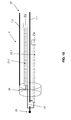
- the Fig. 1 shows in connection with a non-illustrated total electrode device for power or voltage between an implantable electromedical device and a therapy and / or diagnostic location, as represented for example by a pacemaker electrode, essentially only a supply line 1, which is in the form of a helix 2 of a conventional medical steel, such as MP35N.
- the lead 1 leads to an electrical contact pole, not shown, which is in electrical contact with a body part and which is represented, for example, by a tip or ring contact pole of the pacemaker electrode.
- a device 3 with a frequency-dependent transmission behavior which at least partially filters out therapeutically and / or diagnostically unwanted signals in at least one defined frequency range, such as over 10 MHz and thus the problems described in the introduction of the high-frequency magnetic field Avoids alternating field.
- the frequency-dependent transmission device 3 is formed by an LC resonant circuit, wherein the inductance L is formed by a over several turns of the coil 2 extending portion 4, which consists of a clear, at least twice better electrically conductive material as the remaining coils.
- Fig. 2 shows the equivalent circuit of the frequency-dependent transmission device 3 in the form of an LC resonant circuit. 6
- Fig. 3 schematically a realization of the resonant circuit 6 with the described inductance L and a arranged around the corresponding portion 4 of the coil 2 around capacitor 7 is shown.
- the latter is realized as a cylindrical capacitor with an inner sleeve 8 and a separate outer sleeve 10 via a dielectric 9.
- the two sleeves 8, 10 are in each case electrically connected to the helical turns at the opposite ends of the section 4, whereby the in Fig. 2a shown parallel connection of the inductance L and the capacitance C is caused.
- eps_r 2.5 to 10 you cover the most common plastics, including glass.
- eps_r> 10 to 100 in order to keep the size low.
- This area also includes, for example, A1203 or Ta205.
- Ceramics as a dielectric with eps_r> 100 to several thousand e.g. Barium titanate.
- the frequency dependence of the frequency-dependent transmission device 3 can also be variably controlled, for example, the capacity C is variable.
- the trimming of the capacitive element can be performed by the (not shown) implant, so for example a pacemaker or defibrillator by a bias voltage.
- the corresponding trim element 11 may be, for example, a voltage-controlled capacitor, varicap or varactor.
- the control parameters can be entered into the implant by external programming.
- a sensor 12 in particular a field sensor for the static magnetic field acting on the electrode device, ie the strength of the magnetic field, and / or the frequency of an RF field can be provided, which detects therapeutically and / or diagnostically unwanted signals.
- a corresponding electrode device is in the 4 and 5 shown.
- the sensor 12 in the form of a dipole, an f / U converter (frequency-voltage converter) 13, a demodulator 14, a threshold value transmitter 15 and a low-pass filter 16 are connected downstream. About the latter, the trim element 11 is adjustable. Overall, the in Fig. 4 shown wiring of the trimming element 11 an interference frequency in a predetermined band and with an amplitude greater than an adjustable threshold.
- the corresponding parameters are based on conventional magnetic fields, as used in known MRI systems with a magnetic field strength of 1.5 T and 3 T.
- the sensor 12 can be arranged in the implant, wherein control lines lead to the frequency-dependent transmission device 3, but is preferable in 4 and 5 illustrated autarkic design, in which the sensor 12 is mounted in the region of the electrode device itself.
- Fig. 5 shows a concrete implementation of the in Fig. 4 Diagram shown circuit.
- the sensor 12 is a dipole, wherein the frequency / voltage (f / U) converter 13 is realized by a voltage divider of two impedances Z1 and Z2.
- the frequency / voltage (f / U) converter 13 is realized by a voltage divider of two impedances Z1 and Z2.
- tuned resonators for certain frequencies can control the corresponding bias voltage.
- Z1 would then be a resistor and Z2 would be an inductance.
- the demodulator 14 is represented by a diode D, which is followed by a threshold value transmitter 15 in the form of the diodes D1, D2 which can be bridged by switches S1, S2.
- the low-pass filter 16 is realized as an RC circuit with the resistor Rt and the capacitor Ct.
- the applied magnetic field corresponding DC voltage then controls the voltage-dependent capacitance C (U) of the resonant circuit 6 at. Its inductance L lies in the electrode feed line 1.
- the voltage-dependent capacitance C (U) may be a capacitance diode (tuning diode, varicap, varactor) or as in the EP 1 299 948 B1 be realized. Since in a design of the impedance Z1 as resistance and the impedance Z2 as inductance, the DC voltage U increases at the frequency f, the capacitance C (U) must be realized so that the capacitance C becomes smaller with increasing control voltage U, so that the effective frequency of Locking device is increased. In the opposite case, the impedance Z2 would have to be chosen as the resistance and the impedance Z1 as the inductance.
- the characteristic curve of the voltage-dependent capacitance C (U) is realized in such a way that the effective frequency follows the frequency f detected by the field sensor 12.
- the frequency / voltage converter 13 may be formed with a correspondingly compensative characteristic.
- the frequency-dependent transmission device 3 is integrated into a so-called fixing helix 17, which represents the distal end of an electrode device designed, for example, as a pacemaker electrode.
- the supply line 1 merges into a housing projection 18, on which the proximal-side turns of the fixing helix 17 are fastened.
- the subsequent to the attachment section 4 is analog Fig. 1 again designed as an inductance L with a good conductive coating 5 of the helical turns.
- the schematically indicated capacitor 7 with its capacitance C can be accommodated in the inner lumen 19 of the section 4 of the fixing helix 17, for example in the housing projection 18. Its housing thus forms the shoulder 20 to which the supply line 1 is attached.
- an electrical connection 21 is provided.
- the distal end of the Fixierhelix 17 is provided with axially expanded turns, which can be "screwed” by a rotation of the Fixierhelix about its longitudinal axis in the body tissue.
- the portion 4 of the fixing helix 17 forming the inductance L is insulated toward the outside in the areas where it can come into tissue contact. The contacting of the supply line 1 and the electrical connection 21 in the region of the shoulder takes place by crimping.
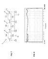
- Fig. 7 is a first circuit realization of the frequency-dependent transmission device 3 at two leads 1.1, 1.2 shown, the resistors, inductors, capacitors and transformers used. Implemented is an elliptical low-pass higher order, wherein serially connected in series parallel circuits of inductors La, Lb, Lc and capacitances Ca, Cb, Cc are switched into the supply line 1.1. A coupling to the supply line 1.2 via capacitors C1, C2, C3, C4 end and between the LC circuits.
- the supply line 1.1. supplies a contact pole of the electrode device, while the second lead 1.2 leads to a further contact pole, such as a ring electrode pole or an ICD shock coil. If no such other pole is present, the lead 1.2 can also lead to a potential reference pole, which is realized only for this purpose as a contact to the tissue, but otherwise has no further function for diagnosis or therapy.
- the potential reference pole is designated G (ground).
- Fig. 8 shows by way of example the frequency response of a frequency-dependent transmission device between 10 and 100 MHz. Recognizable takes place until shortly before the cutoff frequency of 100 MHz, no relevant attenuation, which then increases with a sharp edge to an attenuation of> 10 dB.
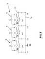
- Fig. 9 shows a frequency-dependent transmission device 3 with oscillating circuits 6 in the form of LC resonators, which are inductively coupled with their inductances La, Lb, Lc via Einkoppelinduktterrorismen La1, Lb1, Lc1 in the supply line 1.1.
- the execution corresponds to Fig. 9 the of Fig. 7 so that reference can be made to the description there.
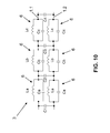
- a frequency-dependent transmission device 3 is shown, which is realized in two leads 1.1, 1.2 to non-illustrated contact poles.
- each supply line 1.1, 1.2 three oscillating circuits 6 are each connected in series with inductance La, Lb, Lc and capacitors Ca, Cb, Cc connected in parallel thereto.
- the two supply lines 1.1, 1.2 are also capacitive over capacitors C1, C2, C3, C4 end and between the resonant circuits coupled. In this embodiment symmetrically balanced low pass filter characteristics are achieved.
- Fig. 11 is a frequency-dependent transmission device 3 for two leads 1.1, 1.2 shown, in which in each case serially in the leads 1.1, 1.2 inductors L are turned on. The leads 1.1, 1.2 are then cross-referenced relative to the respective inductors L capacitively coupled by the capacitors 7 with the capacitance C.
- the purpose of this interconnection is to largely extinguish voltages caused in the inductors by electromagnetic alternating field. This is based on the fact that the two supply lines 1.1, 1.2 experience a substantially equal, tangential E field strength, since they are geometrically close to each other.
- the voltages caused in the inductors L overlap in antiphase due to the crossed coupling by the capacitors 7, whereby an extinction occurs.
- FIGS. 12 and 13 An analogous crosstalk of inductances in three Zu meeting 1.1, 1.2, 1.3 show the FIGS. 12 and 13 , While in Fig. 12 all cross-combinations are coupled by capacitors 7 are in the embodiment according to Fig. 13 omitted some coupling capacitors, which leads to no significant impairment of the voltage cancellation.
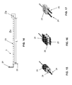
- Frequency-dependent transmission devices 3 are shown, which are based on the principle of waveguides. Like from the 15 to 17 becomes clear, these waveguides 23 consist of two adjacent conductors 24, 25, which are coupled via a dielectric 26. The waveguide 23 is thus characterized by a specific wave impedance Z0. Depending on the terminating impedance Za, which connects the two conductors 24, 25 of the waveguide 23, then an impedance Z is established at the opposite end between these conductors 24, 25.
- the termination impedance Za can be realized for example by a circuit of resistors R, inductors L, capacitors C and transmitters Ü.
- the components are to be dimensioned such that for a given length 1 of the waveguide 23, the desired impedance Z is set at the other end.
- Za and 1 In order to realize a filtering at a certain frequency, so for example a lock, Za and 1 must be designed so that Z ideally a severed line simulated. Then there is the case of a frequency-dependent line break. In the simplest, preferred case Za is a short circuit, then the low-frequency therapy and diagnostic currents can flow undisturbed.
- the length is determined in accordance with the specific wave impedance Z0, for which purpose a so-called "Smith Chart" is used.
- the procedure is reversed in exactly the opposite way.
- the termination Za remains open, over the length 1 of the waveguide 23, the impedance is then transformed so that at the corresponding frequency at the other end, a frequency-dependent short circuit occurs. For low-frequency currents, this short circuit does not exist, so that therapy and diagnosis are not impaired.
- the waveguide is cylindrical, wherein a coaxial inner conductor 24 and a tubular outer conductor 25 are coupled through the dielectric 26.
- Fig. 16 are planar, elongated conductors 24, 25 sandwiched and placed in between the dielectric 26th
- Fig. 17 For example, two wire-shaped conductors 24, 25 are positioned in a bar-shaped block of dielectric 26.
- FIG Fig. 18 A circuit realization of a frequency-dependent transmission device in an electrode device with two supply lines 1.1, 1.2 using waveguides 23.1, 23.2 is shown in FIG Fig. 18 shown.
- the distal end of an electrode device in the form of a heart electrode 27 is shown, which has a ring contact pole 28 and a tip pole 29.
- the feed line 1.1 the first waveguide 23.1 is turned on
- the feed line 1.2 supplies the ring contact pole 28.
- the second waveguide 23.2 is turned on.
- a frequency-dependent line interruption (current block) is realized on the supply line 1.1.
- a frequency-dependent short circuit is caused by means of the waveguide.
- the supply line 1.2 can also have a waveguide installed, as is the case with the supply line 1.1. Then, an interruption point is realized shortly before the ring contact pole 28.
- ring contact pole 28 and tip contact 29 corresponds to the embodiment according to Fig. 18 .
- two waveguides 23.1, 23.2 coupled in a consistent manner in the supply line 1.1 or line connection 30.
- the frequency-dependent transmission device 3 formed can be used simultaneously for operation at a plurality of frequencies.
- the networks 31 interposed in the waveguides 23 are each active for a given MRI frequency, so that a patient with a network as in FIG Fig. 19 implanted cardiac electrode in common MRI systems with 1.5 T, 3 T and 7 T magnetic field strength without problems remain.
- Fig. 20 combined with Fig. 21 visualizes the interposition of the networks 31 in the conductors 24, 25 of the waveguide 23.
- the conductors 24, 25 interrupted, at their connection points 32 are in Fig. 21 a to l network implementations shown connectable.
- various short-circuit and interruption variants Fig. 21b, f, i and l
- various combinations of intermediate parallel LC resonant circuits Fig. 21, a, c, e and j
- serial LC-links Fig. 21, d, g, h and k
- Fig. 22 shows a waveguide variant of the frequency-dependent transmission device 3, in which over a certain length of the feed line 1, a coiled waveguide 23 is used with the same diameter and the same helix pitch.
- the "helical thread" is quasi two-start and alternately through the helices of the supply line 1 and the waveguide 23 is formed.
- the conductors 24, 25 are connected to the lead-away or away-carrying portion of the feed line 1.
- the waveguide termination Za at the proximal end of the waveguide 23 is shown.
- FIGS. 23 to 26 show more complex implementations of electrode devices 27 with frequency dependent transmitters 3. So shows Fig. 23 a cardiac electrode 27 with a coiled outer conductor as a feed line 1.1 to a ring contact pole 28. In this outer conductor runs an inner conductor as a feed line 1.2 beyond the distal end of the feed line 1.1 and includes, for example, a (not shown) tip electrode electrically.
- the outer feed line 1.1 is designed at its end via a section 4 as inductance L by a correspondingly highly conductive coating 5.
- a section 4 is analogous Fig. 3 positioned a cylinder condenser 7 with inner sleeve 8, dielectric 9 and outer sleeve 10, which lies within the ring contact pole 28.
- the latter is electrically connected to the inner sleeve 8 of the capacitor 7, which in turn is connected to the distal end of the inductance L.
- Its proximal end is electrically connected to the outer sleeve 10, so that between supply line 1.1 and ring contact pole 28 is a parallel connection of the inductance L and the capacitance C of the capacitor 7.
- An analog frequency-dependent transmission device 3 is arranged offset in the outer conductor in the region of the inner feed line 1.2 distal to the transmission device 3. Again, an inductance L is in turn applied in the manner described within the coiled feed line 1.2, which is electrically connected at their end-facing end spirals with the outer and inner sleeve of the cylinder capacitor 7.
- a frequency-dependent transmission device 3 in the form of a frequency-dependent current blocking along the inner lead 1.2 of a heart electrode with high-pass behavior between the outer lead 1.1 and the inner lead 1.2 again.
- This pitch sensor 33 is designed in the form of an internal thread, in which the portion 4 of the inner feed line 1.2 designed as an inductance L is rotatable and thus displaceably mounted in a rotation in the axial direction.
- the last threads 34, 35 of the pitch sensor 33 which are each in the distal or proximal direction, are each designed to be electrically conductive and make contact with the turn of the coil forming the inductance L therein.
- the distally located thread 34 is electrically connected to the inner sleeve 8 of a cylindrical capacitor 7 arranged around the inductance L, the proximal thread 35 to the corresponding outer sleeve 10.
- the capacitor C formed by the dielectric 9 between the two sleeves 8, 10 is therewith connected in parallel to the inductance L between the two threads 34, 35 in the feed line 1.2 to the tip contact pole 29, as shown in the equivalent circuit diagram Fig. 24B becomes clear.
- Fig. 25 illustrated embodiment is different from the Fig. 24 only in that the energy absorbed by the electrode line meets different electronic components.
- the energy comes in the considered case from the proximal end and meets in the Fig. 25 first on a voltage divider while in Fig. 24 the energy first hits the bypass capacitor and residual energy is damped by the serially lying oscillating cone (blocking circuit).
- Fig. 26 shows a detail of an electrode device in which for the coiled inner lead 1.2 with an integrated pitch sensor 33, a low pass for the inner lead 1.2 is realized.
- an inductance L is again applied via a section 4 through a highly conductive coating or the like in the coiled feed line 1.2.
- the respective last helical turns of the inductance L in the proximal or distal direction are on the one hand connected to the inner sleeve 8 or outer sleeve 9 of a cylindrical capacitor 7, which is analogous Fig. 3 is constructed, electrically connected, so that in turn a parallel connection of the elements L and C is obtained (s. Fig. 26b) ,
- a ring contact pole 28 is placed, which is connected via the outer coiled feed line 1.1 to the implant.
- a pitch sensor 33 in the form of threads is formed, which is capacitively coupled to the outer sleeve 10 of the cylindrical capacitor 7 via a dielectric 36.
- annular sleeve 37 connected electrically to the inner sleeve of the cylindrical capacitor 7 is arranged distally in front of the cylindrical capacitor 7 within the ring contact pole 28, which in turn is capacitively coupled to the capacitor C1 via a dielectric 38 to the ring contact pole 28.
- the two leads 1.1, 1.2 are also capacitively coupled distally of the LC resonant circuit via the capacitor C1 (s. Fig. 26b) ,
Abstract
Description
Die Erfindung betrifft eine Elektrodenvorrichtung zur Strom- oder Spannungsführung zwischen einem implantierbaren elektromedizinischen Gerät und einem Therapie- und/oder Diagnoseort im menschlichen Körper, wobei die Elektrodenvorrichtung mindestens eine strom-/spannungsführende Zuleitung und mindestens einen elektrischen Kontaktpol zu einem Körperteil aufweist.The invention relates to an electrode device for current or voltage conduction between an implantable electromedical device and a therapy and / or diagnosis in the human body, wherein the electrode device has at least one current / voltage-carrying lead and at least one electrical contact pole to a body part.
Zum Hindergrund der Erfindung ist festzuhalten, dass der Erfindungsgegenstand in erster Linie im Zusammenhang mit Herzschrittmachern, implantierbaren Defibrillatoren und anderen Typen von aktiven implantierbaren elektromedizinischen Geräten relevant ist. Letztere weisen in aller Regel mindestens eine strom-/spannungsführende Zuleitung in der Elektrodenvorrichtung-üblicherweise als kurz als "Elektrode" bezeichnet - auf, deren distales Ende beispielsweise in einer Herzkammer angeordnet und zur Messung kardiologischer Potentialsignale oder zur Abgabe entsprechender therapeutischer Stromsignale dient.For the purposes of the invention, it should be noted that the subject matter of the invention is primarily relevant in the context of pacemakers, implantable defibrillators and other types of active implantable electromedical devices. The latter usually have at least one current / voltage-carrying lead in the electrode device-usually referred to as "electrode" for short-whose distal end is arranged, for example, in a heart chamber and serves to measure cardiac potential signals or to deliver corresponding therapeutic current signals.
Die Kompatibilität derartiger Elektrodenvorrichtungen bei implantierbaren elektromedizinischen Geräten mit hochfrequenten Magnetfeldern, wie sie insbesondere bei bildgebenden diagnostischen Verfahren auf Magnetresonanz-Basis ― sogenannte MRI- (magnetic resonance imaging) Verfahren ― verwendet werden, stellt ein gravierendes Problem dar. Bei solchen MRI-Verfahren wird einem starken statischen Magnetfeld ein mit Radiofrequenz (RF) gepulstes magnetisches Wechselfeld überlagert, das dazu dient, den Energiestatus der Protonen im untersuchten Gewebe zu verändern und entsprechende MRI-Signale aus dem Gewebe zu produzieren.The compatibility of such electrode devices in implantable electromedical devices with high-frequency magnetic field, as used in particular in magnetic resonance imaging diagnostic methods - so-called MRI (magnetic resonance imaging) method - is a serious problem. In such MRI method is a strong static magnetic field superimposed on a radio frequency (RF) pulsed alternating magnetic field, which serves to change the energy state of the protons in the examined tissue and to produce corresponding MRI signals from the tissue.
Dieses magnetische Wechselfeld führt nach den Gesetzen der elektromagnetischen Induktion in den Zuleitung der hier in Rede stehenden Elektrodenvorrichtungen von elektromedizinischen Geräteimplantaten zu Wechselspannungen, deren Energie insbesondere an den elektrisch leitenden Kontaktpolen der Elektrodenvorrichtung zum menschlichen Gewebe in Wärme umgesetzt wird. Dies kann zu einer erheblichen Erhitzung beispielsweise des Spitzenkontaktes einer Herzelektrode mit einer entsprechenden Beeinträchtigung und sogar Schädigung des damit in Berührung stehenden oder umliegenden Herzgewebes führen.This alternating magnetic field leads according to the laws of electromagnetic induction in the lead of the electrode devices in question of electromedical device implants to AC voltages whose energy is converted in particular to the electrically conductive contact poles of the electrode device to human tissue into heat. This can result in significant heating of, for example, the tip contact of a cardiac electrode with a corresponding impairment and even damage to the cardiac tissue in contact or surrounding it.
Um diese Problematik zu vermeiden, schlägt die
Der Erfindung liegt die Aufgabe zugrunde, gattungsgemäße Elektrodenvorrichtungen, wie sie beispielsweise durch Herzschrittmacher-Elektroden realisiert sind, so zu verbessern, dass Filtermaßnahmen ohne wesentliche Beeinträchtigung der praktischen Einsatzmöglichkeiten umgesetzt werden können.The invention has for its object to improve generic electrode devices, such as those implemented by pacemaker electrodes, so that filter measures can be implemented without significant impairment of practical applications.
Diese Aufgabe wird in ihrer allgemeinsten Ausprägung durch die kennzeichnenden Merkmale des Anspruches 1 gelöst. Demnach ist der strom-/spannungsführenden Zuleitung der Elektrodenvorrichtung mindestens ein Abschnitt mit einem frequenzabhängigen Übertragungsverhalten zugeordnet, wobei dieser mindestens eine frequenzabhängige Übertragungsabschnitt therapeutisch und/oder diagnostisch unerwünschte Signale in mindestens einem definierten Frequenzbereich zumindest teilweise ausfiltert.This object is achieved in its most general form by the characterizing features of
Durch dieses frequenzabhängige Übertragungsverhalten ist die Elektrodenvorrichtung so angepasst, dass sie in einem Magnetresonanz-Umfeld schädliche Wechselspannungen aufgrund des magnetischen Wechselfeldes ausfiltert und eine Erwärmung der Zuleitung zu dem elektrischen Kontaktpol der Elektrodenvorrichtung wirkungsvoll unterbindet. Insoweit fließen also keine unerwünschten Ströme in den Körper des Patienten. Die erfindungsgemäß vorgesehene Ausfilterung von Frequenzen oder Frequenzbereichen kann sich auch in einer Umverteilung der induzierten Wechselströme in der Zuleitung zwischen verschiedenen Kontaktpolen äußern, was ebenfalls eine Erwärmung der Zuleitung und der Kontaktpole wirkungsvoll verhindert.As a result of this frequency-dependent transmission behavior, the electrode device is adapted such that it filters out harmful alternating voltages due to the alternating magnetic field in a magnetic resonance environment and effectively prevents heating of the supply line to the electrical contact pole of the electrode device. In that regard, so no unwanted currents flow into the body of the patient. The inventively provided filtering of frequencies or frequency ranges may also manifest itself in a redistribution of the induced alternating currents in the supply line between different contact poles, which also effectively prevents heating of the supply line and the contact poles.
Gemäß bevorzugter Weiterbildungen der Erfindung kann das frequenzabhängige Übertragungsverhalten einem Tiefpass-, Bandsperr-, Bandpass- oder Hochpassfilter entsprechen. Die Tiefpass-Charakteristik kann beispielsweise eine Grenzfrequenz von 100 kHz, besonders bevorzugt 10kHz, mit einer Flanke von > = 6 dB/Oktave aufweisen. Bei einem Bandsperrfilter kann das Frequenz-Sperrband beispielsweise zwischen 10 MHz und 3 Ghz liegen. Diese Frequenzcharakteristik ist für das frequenzabhängige Übertragungsverhalten vom implantierten elektromedizinischen Gerät zum Therapie-/Diagnoseort genauso von Vorteil wie das oben erwähnte Tiefpass-Verhalten.According to preferred developments of the invention, the frequency-dependent transmission behavior can correspond to a lowpass, bandstop, bandpass or highpass filter. The low-pass characteristic can have, for example, a cutoff frequency of 100 kHz, particularly preferably 10 kHz, with a slope of> = 6 dB / octave. For example, with a band rejection filter, the frequency rejection band may be between 10 MHz and 3 Ghz. This frequency characteristic is just as advantageous for the frequency-dependent transmission behavior of the implanted electromedical device to the therapy / diagnosis as the above-mentioned low-pass behavior.
Für das frequenzabhängige Übertragungsverhalten zwischen verschiedenen Kontaktpolen am Therapie-/Diagnoseort ist die erwähnte Hochpass-Charakteristik mit einer Grenzfrequenz > 100 kHz und einer Flanke von > 6 dB/Oktave oder ein Bandpassverhalten mit einer Mittenfrequenz zwischen 10 MHz und 3 Ghz von Vorteil. Die Filtergüte bei einem Bandsperr- oder Hochpass-Filter sollte einen Wert von über 20 aufweisen.For the frequency-dependent transmission behavior between different contact poles at the therapy / diagnosis site, the aforementioned high-pass characteristic with a cutoff frequency> 100 kHz and a slope of> 6 dB / octave or a bandpass characteristic with a center frequency between 10 MHz and 3 GHz is advantageous. The filter quality for a band stop or high pass filter should be greater than 20.
Zu dem die Strom-/Spannungsführung bildenden Leiter ist festzuhalten, dass dieser eine Isolation aufweist, die eine mindestens 100-fach geringere Gleichstrom-Leitfähigkeit als der Leiter selbst aufweist. Letzterer kann üblicher Weise aus Metall, aber auch aus leitendem Kunststoff, Kohlefasern, einer leitfähigen Flüssigkeit usw. bestehen.It should be noted that the conductor forming the current / voltage guide has an insulation which has at least 100 times less direct current conductivity than the conductor itself. The latter can usually be made of metal, but also of conductive plastic, carbon fibers, a conductive liquid, etc.
Gemäß einer bevorzugten Ausführungsform der Erfindung kann die frequenzabhängige Übertragungseinrichtung eine Durchführung mit einem vorzugsweisen Mindestdurchmesser von 0,2 mm für einen Führungsdraht, Guidewire, Mandrin oder dergleichen aufweisen. Im Gegensatz zum Stand der Technik ist damit die erfindungsgemäße Elektrodenvorrichtung trotz der vorhandenen Ausfilterung induzierter Spannungen über einen Führungsdraht in entsprechende Körpergefäße einführbar.According to a preferred embodiment of the invention, the frequency-dependent transmission device may have a passage with a preferred minimum diameter of 0.2 mm for a guide wire, guidewire, stylet or the like. In contrast to the prior art, the electrode device according to the invention can thus be introduced into corresponding body vessels via a guide wire despite the existing filtering out of induced voltages.
Grundsätzlich kann die frequenzabhängige Übertragungseinrichtung eine oder mehrere Zuleitungen in der implantierbaren Elektrodenvorrichtung kontaktieren. Die Übertragungseinrichtung ist dann an geeigneten Positionen der Zuleitung daran angeschlossen.In principle, the frequency-dependent transmission device can contact one or more supply lines in the implantable electrode device. The transmission device is then connected thereto at suitable positions of the supply line.
Eine besonders geschickte Weiterbildung liegt darin, dass die frequenzabhängige Übertragungseinrichtung durch einen oder mehrere Abschnitte der strom-/spannungsführenden Zuleitung selbst gebildet ist, wie dies beispielsweise durch einen höher leitfähigen Abschnitt einer Wendel der Zuleitung ausgeführt sein kann. Bevorzugtermaßen sollte ein entsprechender Abschnitt der gewendelten Zuleitung eine mindest doppelt so hohe elektrische Leitfähigkeit wie die umgebenden Bereiche der Zuleitung aufweisen. Die höher leitfähige Auslegung des entsprechenden Wendelabschnittes kann durch eine hoch leitfähige Beschichtung oder eine Dotierung des Wendelmaterials in diesem Abschnitt hervorgerufen werden. Dabei sollten vorzugsweise die Windungen in dem höher leitfähigen Abschnitt der Wendel nach außen isoliert sein, damit zwischen den einzelnen Windungen der Wendel keine Kurzschlüsse auftreten.A particularly clever development is that the frequency-dependent transmission device is formed by one or more sections of the current / voltage-carrying lead itself, as can be carried out for example by a higher conductive portion of a coil of the supply line. Preferred dimensions should have a corresponding portion of the coiled feed line at least twice as high electrical conductivity as the surrounding areas of the feed line. The higher conductive design of the corresponding helical section can be caused by a highly conductive coating or a doping of the helical material in this section. In this case, preferably, the turns should be insulated in the higher conductive portion of the helix to the outside, so that no short circuits occur between the individual turns of the helix.
Eine konstruktiv vorteilhafte Ausbildung einer entsprechenden frequenzabhängigen Übertragungseinrichtung ist durch einen Induktivität-Kapazität-(LC)-Resonator realisiert, bei dem der höher leitfähige Abschnitt der Wendel als Induktivität mit einem parallel geschalteten Kondensator kombiniert ist. Bevorzugtermaßen ist dabei der höher leitfähige Wendelabschnitt, der die Induktivität realisiert, beispielsweise vergoldet, um eine hohe Güte des LC-Schwingkreises zur gewährleisten.A structurally advantageous embodiment of a corresponding frequency-dependent transmission device is realized by an inductance capacitance (LC) resonator, in which the higher conductive portion of the coil is combined as an inductance with a parallel-connected capacitor. Preferred measures here is the higher conductive coil section, which realizes the inductance, for example, gold plated to ensure a high quality of the LC resonant circuit.
Eine sehr kompakte Weiterbildung eines solchen LC-Resonators ergibt sich durch eine Erfindungsvariante, bei der der Kondensator durch einen um den leitfähigen Abschnitt der Wendel herum und/oder innerhalb des leitfähigen Abschnitts der Wendel angeordneten Zylinder-Kondensator gebildet ist. Dies stellt eine besonders klein bauende Ausführungsform der erfindungsgemäßen Elektrodenvorrichtung dar, bei der der Wendelinnenraum als Durchführung für einen Führungsdraht zur Verfügung bleibt und/oder gerade dieser für den Aufbau genutzt wird.A very compact development of such an LC resonator results from a variant of the invention in which the capacitor is surrounded by a conductive portion of the Spiral around and / or within the conductive portion of the helix arranged cylinder capacitor is formed. This represents a particularly small-scale embodiment of the electrode device according to the invention, in which the helix interior remains available as lead-through for a guide wire and / or is used for the construction.
Gemäß einer weiteren bevorzugten Weiterbildung der Erfindung ist die Frequenzabhängigkeit der Übertragungseinrichtung variabel steuerbar. Damit kann die Elektrodenvorrichtung an die jeweiligen Umstände, nämlich die Frequenz der induzierten Störsignale angepasst werden. Damit bleibt die Elektrodenvorrichtung unabhängig von ihrer MRI-Umgebung universell einsetzbar.According to a further preferred embodiment of the invention, the frequency dependence of the transmission device is variably controllable. Thus, the electrode device can be adapted to the particular circumstances, namely the frequency of the induced interference signals. Thus, the electrode device remains universally applicable regardless of their MRI environment.
Bevorzugter Weise erfolgt die Steuerung der Frequenzabhängigkeit mit Hilfe eines Trimmelementes, wie etwa einem spannungsgesteuerten Kondensator, einem sogenannten Varicap oder einem Varactor. Auch eine Biasspannung ist zur Frequenzsteuerung verwendbar. Eine solche Steuerspannung kann durch eine Programmierung des elektromedizinischen Gerätes selbst oder durch einen Sensor zur Erfassung therapeutisch und/oder diagnostisch unerwünschter Signale erzeugt werden. Der Sensor kann dabei eine Störfrequenz in einem vorgegebenen Frequenzband und/oder mit einer bestimmten Amplitude größer einer einstellbaren Schwelle detektieren. Insoweit kann eine Elektrodenvorrichtung eines implantierbaren elektromedizinischen Gerätes in mehreren üblichen Magnetfeldbereichen von MRI-Systemen, also beispielsweise 1,5 und 3,0 T im Gegensatz zu einer konstruktiv fest verdrahteten Variante eingesetzt werden.Preferably, the control of the frequency dependence by means of a trimming element, such as a voltage-controlled capacitor, a so-called varicap or a varactor. A bias voltage can also be used for frequency control. Such a control voltage can be generated by programming the electromedical device itself or by a sensor for detecting therapeutically and / or diagnostically unwanted signals. The sensor can detect an interference frequency in a predetermined frequency band and / or with a certain amplitude greater than an adjustable threshold. In that regard, an electrode device of an implantable electromedical device can be used in several conventional magnetic field ranges of MRI systems, ie, for example 1.5 and 3.0 T in contrast to a structurally hard-wired variant.
Für die Positionierung des Sensors bestehen verschiedene bevorzugte Varianten, so kann er im implantierten elektromedizinischen Gerät selbst angeordnet oder in der Zuleitung der Elektrodenvorrichtung zugeordnet sein. Im erstgenannten Fall führen entsprechende Steuerleitungen zur frequenzabhängigen Übertragungseinrichtung, um deren Frequenzabhängigkeit zu steuern.For the positioning of the sensor, there are various preferred variants, it may be arranged in the implanted electromedical device itself or assigned in the lead of the electrode device. In the former case, corresponding control lines lead to the frequency-dependent transmission device in order to control their frequency dependence.
Bei einer Zuordnung des Sensors zur Zuleitung arbeitet der Sensor im Wesentlichen autark, also ohne das implantierbare elektromedizinische Gerät, womit sich der Verdrahtungsaufwand für die Steuerung der Frequenzabhängigkeit verringert. Als Sensor kommt vorteilhafter Weise ein Feldsensor für elektrische, magnetische und/oder elektromagnetische Felder, wobei die Felder statische und/oder Wechselfelder sind, in Form insbesondere eines Dipols zum Einsatz.When the sensor is assigned to the supply line, the sensor operates essentially autonomously, ie without the implantable electromedical device, thus reducing the wiring complexity for frequency dependence control. As a sensor is advantageously a field sensor for electrical, magnetic and / or electromagnetic fields, the fields are static and / or alternating fields, in the form of a particular dipole used.
Eine weitere Variante für die frequenzabhängige Übertragungseinrichtung liegt in deren Bildung durch einen Schwingkreis. Dabei wird das frequenzabhängige Übertragungsverhalten durch elektrische Wirkelemente in Form eines Widerstands R, einer Kapazität C, Induktivität L oder mit Hilfe von Überträgern Ü bedarfsgerecht realisiert. Dabei kommen Wirkelemente-Kombinationen wie RL, RC, RLC, RÜ, CÜ oder RLCÜ zum Einsatz. Ein oder mehrere solche Schwingkreise können kombiniert werden, wobei vorzugsweise eine induktive Ankopplung an eine oder mehrere Zuleitungen möglich ist.Another variant of the frequency-dependent transmission device is in their formation by a resonant circuit. In this case, the frequency-dependent transmission behavior is realized as required by electrical active elements in the form of a resistor R, a capacitor C, inductance L or with the aid of transmitters Ü. Active element combinations such as RL, RC, RLC, RÜ, CÜ or RLCÜ are used. One or more such resonant circuits can be combined, wherein preferably an inductive coupling to one or more leads is possible.
Eine konstruktiv geschickte Anbindung der frequenzabhängigen Übertragungseinrichtung ist möglich, indem diese an einer Fixierhelix an der Elektrodenvorrichtung ausgebildet ist. Insbesondere ist eine Induktivität aus einem Teil der Fixierhelix geformt.A constructively clever connection of the frequency-dependent transmission device is possible by being formed on a fixing helix on the electrode device. In particular, an inductance is formed from a part of the fixing helix.
Eine weitere konzeptionelle Variante für die frequenzabhängige Übertragungseinrichtung liegt in der Realisierung mit Hilfe eines oder mehrerer Wellenleiter, die eine frequenzspezifische Wellenimpedanz aufweisen. Das Wellenleiterkonzept kann dabei für sich oder auch in Kombination mit den anderen Frequenzsteuerungsmechanismen, wie den oben erwähnten Schwingkreisen kombiniert werden.Another conceptual variant of the frequency-dependent transmission device is the realization by means of one or more waveguides having a frequency-specific wave impedance. The waveguide concept can be combined alone or in combination with the other frequency control mechanisms, such as the above-mentioned oscillating circuits.
Bevorzugter Weise sind die oder der Wellenleiter durch eine Abschlussimpedanz abgeschlossen, bei der es sich im einfachsten Fall um einen Kurzschluss handelt.Preferably, the waveguide or waveguides are terminated by a terminating impedance, which in the simplest case is a short circuit.
Zur Frequenzanpassung an mindestens zwei unerwünschte Signalfrequenzen können in den oder die Wellenleiter Netzwerke zwischengeschaltet sein und/oder der Abschluss eines Wellenleiters durch ein Netzwerk erfolgen. Damit ist eine hohe Variabilität in der Frequenzanpassung erreichbar.In order to adapt the frequency to at least two unwanted signal frequencies, networks may be interposed in the waveguide (s) and / or the termination of a waveguide may be performed through a network. Thus, a high variability in the frequency adjustment is achievable.
Grundsätzlich kann jeder Wellenleiter durch zwei über ein Dielektrikum gekoppelte Leiter gebildet sein.In principle, each waveguide can be formed by two conductors coupled via a dielectric.
Eine in sich kompakte Ausführung für die Zuordnung des Wellenleiters zu einer strom-/spannungsführenden Zuleitung ist durch eine gewendelte Ausbildung des Wellenleiters und eine Integration in eine als Wendelleitung ausgebildete strom-/spannungsführende Zuleitung gegeben.An inherently compact design for the assignment of the waveguide to a current / live lead is given by a coiled design of the waveguide and an integration in a trained as a helical line current / live lead.
Weitere Merkmale, Einzelheiten und Vorteile der Erfindung ergeben sich aus den nachfolgenden Beschreibungen einer Vielzahl von Ausführungsbeispielen anhand der beigefügten Zeichnungen. Es zeigen:
- Fig. 1
- eine schematische Ansicht einer Zuleitung einer Elektroden-vorrichtung zur Strom- oder Spannungsführung zwischen einem implantierbaren elektromedizinischen Gerät und einem Therapie- und/oder Diagnoseort mit einer integrierten frequenzabhängigen Übertragungseinrichtung und einen Detail-Querschnitt durch die Zuleitung,
- Fig. 2a und b
- Ersatzschaltbilder für die frequenzabhängige Übertragungsein-richtung in Form eines LC-Gliedes mit fester und veränderlicher Kapazität des Kondensators
- Fig. 3
- eine schematische Darstellung einer Zuleitung mit integrierter frequenzabhängiger Übertragungseinrichtung in einer weiteren Ausführungsform,
- Fig. 4
- ein Blockdiagramm einer Zuleitung mit Übertragungseinrichtung mit einer steuerbaren Frequenzabhängigkeit,
- Fig. 5
- ein Schaltbild einer schaltungstechnischen Realisierung der Anordnung gemäß
Fig. 4 , - Fig. 6
- eine schematische Ansicht einer in eine Fixierhelix einer Elektrodenvorrichtung integrierten frequenzabhängigen Übertragungseinrichtung,
- Fig. 7
- ein Schaltbild einer Elektrodenvorrichtung mit zwei Zuleitungen und Schwingkreisen als frequenzabhängige Übertragungseinrichtungen,
- Fig. 8
- das Dämpfungsverhalten einer frequenzabhängigen Übertragungseinrichtung in Form eines elliptischen Tiefpasses 8. Ordnung,
- Fig. 9
- einen Schaltplan einer Elektrodenvorrichtung mit zwei Zuleitungen und induktiv angekoppelten Schwingkreisen als frequenzabhängige Übertragungseinrichtung,
- Fig. 10
- eine Variante der Elektrodenvorrichtung von
Fig. 7 mit in beide Zuleitungen integrierten Schwingkreisen, - Fig. 11
- ein Schaltbild einer Elektrodenvorrichtung mit zwei Zuleitungen, die induktive Abschnitte und kapazitive Kreuzkopplungen aufweisen,
- Fig. 12
und 13 - analoge Schaltpläne von Elektrodenvorrichtungen mit drei Zuleitungen,
- Fig. 14
- eine schematische Ansicht einer Elektrodenvorrichtung mit zwei Zuleitungen und einem Wellenleiter als frequenzabhängige Übertragungseinrichtung,
- Fig. 15
bis 17 - schematische ausschnittsweise Perspektivdarstellungen eines Wellenleiters in unterschiedlichen Realisierungen,
- Fig. 18
- eine schematische Ansicht einer Elektrodenvorrichtung mit zwei Kontaktpolen und Zuleitungen und Wellenleitern als frequenzabhängige Übertragungseinrichtungen,
- Fig. 19
- eine Elektrodenvorrichtung analog
Fig. 18 mit zusätzlichen Netzwerken in den Wellenleitern, - Fig. 20
- einen schematischen Detailausschnitt eines Wellenleiters mit Netzwerk gemäß
Fig. 19 , - Fig. 21A
bis 1 Schaltschemata unterschiedlicher Varianten für die Netzwerke gemäßFig. 19 ,und 20- Fig. 22
- eine weitere alternative Ausführungsform eines in eine Zuleitung integrierten Wellenleiters als frequenzabhängige Übertragungseinrichtung,
- Fig. 23
- eine schematische Darstellung einer Elektrodenvorrichtung mit Innen- und Außenleiter und diesen zugeordneten frequenzabhängigen Übertragungseinrichtungen,
- Fig. 24A/B-Fig. 26A/B
- schematische Darstellungen von Elektrodenvorrichtungen mit integrierten frequenzabhängigen Übertragungseinrichtungen mit den entsprechenden Ersatzschaltbildern.
- Fig. 1
- 1 a schematic view of a supply line of an electrode device for current or voltage conduction between an implantable electromedical device and a therapy and / or diagnosis site with an integrated frequency-dependent transmission device and a detail cross section through the supply line;
- Fig. 2a and b
- Equivalent circuit diagrams for the frequency-dependent Übertragungssein-direction in the form of a LC element with fixed and variable capacitance of the capacitor
- Fig. 3
- a schematic representation of a supply line with integrated frequency-dependent transmission device in a further embodiment,
- Fig. 4
- a block diagram of a supply line with transmission device with a controllable frequency dependence,
- Fig. 5
- a circuit diagram of a circuit realization of the arrangement according to
Fig. 4 . - Fig. 6
- FIG. 2 a schematic view of a frequency-dependent transmission device integrated in a fixing helix of an electrode device, FIG.
- Fig. 7
- a circuit diagram of an electrode device with two leads and resonant circuits as frequency-dependent transmission facilities,
- Fig. 8
- the damping behavior of a frequency-dependent transmission device in the form of an elliptic low-pass 8th order,
- Fig. 9
- a circuit diagram of an electrode device with two leads and inductively coupled resonant circuits as a frequency-dependent transmission device,
- Fig. 10
- a variant of the electrode device of
Fig. 7 with resonant circuits integrated in both supply lines, - Fig. 11
- a circuit diagram of an electrode device with two leads, the inductive sections and capacitive cross-coupling,
- FIGS. 12 and 13
- Analog circuit diagrams of electrode devices with three supply lines,
- Fig. 14
- a schematic view of an electrode device with two leads and a waveguide as a frequency-dependent transmission device,
- 15 to 17
- schematic fragmentary perspective views of a waveguide in different implementations,
- Fig. 18
- a schematic view of an electrode device with two contact poles and leads and waveguides as a frequency-dependent transmission devices,
- Fig. 19
- an electrode device analog
Fig. 18 with additional networks in the waveguides, - Fig. 20
- a schematic detail of a waveguide with network according to
Fig. 19 . - Fig. 21A
- to 1 schematics of different variants for the networks according to
FIGS. 19 and 20 . - Fig. 22
- a further alternative embodiment of a waveguide integrated in a feed line as a frequency-dependent transmission device,
- Fig. 23
- a schematic representation of an electrode device with inner and outer conductors and their associated frequency-dependent transmission devices,
- Fig. 24A / B-Fig. 26A / B
- schematic representations of electrode devices with integrated frequency-dependent transmission devices with the corresponding equivalent circuit diagrams.
Die
Das grundsätzliche Konzept der vorliegenden Erfindung erschließt sich aus dieser
Im gezeigten Ausführungsbeispiel gemäß
In
Weiter bevorzugt wären dann Keramiken als Dielektrikum mit eps_r > 100 bis einige tausend z.B. Bariumtitanat.Further preferred would be ceramics as a dielectric with eps_r> 100 to several thousand e.g. Barium titanate.
Wie in
Alternativ dazu kann ein Sensor 12, insbesondere ein Feldsensor für das die Elektrodenvorrichtung beaufschlagende statische magnetische Feld, also die Stärke des Magnetfeldes, und/oder die Frequenz eines HF Feldes vorgesehen sein, der therapeutisch und/oder diagnostisch unerwünschte Signale erfasst. Eine entsprechende Elektrodenvorrichtung ist in den
Der Demodulator 14 ist durch eine Diode D repräsentiert, der ein Schwellwertgeber 15 in Form der durch Schalter S1, S2 überbrückbaren Dioden D1, D2 folgt. Der Tiefpassfilter 16 ist als RC-Schaltung mit dem Widerstand Rt und dem Kondensator Ct realisiert.The
Die so geglättete, dem anliegenden Magnetfeld entsprechende Gleichspannung steuert dann die spannungsabhängige Kapazität C(U) des Schwingkreises 6 an. Dessen Induktivität L liegt in der Elektroden-Zuleitung 1.The thus smoothed, the applied magnetic field corresponding DC voltage then controls the voltage-dependent capacitance C (U) of the
Die spannungsabhängige Kapazität C(U) kann eine Kapazitätsdiode (Abstimmdiode, Varicap, Varactor) sein oder wie in der
Für die Variante einer Bandsperre ist zu beachten, dass die Kennlinie der spannungsabhängigen Kapazität C(U) so realisiert wird, dass die Wirkfrequenz der mit dem Feldsensor 12 erfassten Frequenz f folgt. Alternativ kann auch der Frequenz-/Spannungswandler 13 mit einer entsprechend kompensativen Kennlinie ausgebildet sein.For the variant of a band-stop filter, it should be noted that the characteristic curve of the voltage-dependent capacitance C (U) is realized in such a way that the effective frequency follows the frequency f detected by the
Die Möglichkeit einer derartigen Justierung der Kapazität gilt im Übrigen für alle in dieser Anmeldung beschriebenen Kapazitäten.Incidentally, the possibility of such an adjustment of the capacity also applies to all capacities described in this application.
Die vorstehend erörterten Varianten der Erfindung sind nochmals kurz wie folgt zu umreißen:
- —
Der Sensor 12 ist Teil eines Reglers, der das frequenzabhängige Übertragungsverhalten an die Frequenz des gerade vorliegenden Störsignals anpasst. - —
Die Übertragungseinrichtung 3 mit frequenzabhängigem Übertragungsverhalten ist mit elektrischen Wirkelementen realisierbar, wie eine RL-, RC-, RLC-, RÜ-, CÜ-, RLCÜ-Schaltung, wobei Ü "Übertrager" bedeutet. - — Wie später noch erläutert wird, können für die frequenzabhängige Übertragung auch Wellenleiter herangezogen werden, die gegebenenfalls auch in Kombination mit den vorstehend erörterten Schwingkreis-Schaltungen verwendbar sind.
- — Die elektrischen Wirkelemente sind durch verteilte Parameter realisiert (Materialeigenschaften, z.B. ein Werkstoff der mechanisch ein Stück ist aber dessen Materialeigenschaften örtlich so verteilt sind, dass sich funktional bestimmte elektrische Bauelemente ausbilden: Z.B. Sandwich aus: leitender Werkstoff, nichtleitenden (besonders dielektrisch ausgeprägter) Werkstoff, leitender Werkstoff bilden in der Flussrichtung dieser Aufzählung einen Kondensator)
- — Alle vorstehenden Maßnahmen können kombiniert werden.
- — Die Dämpfung, die durch eine oder als Gesamteffekt mehrerer frequenzabhängiger Übertragungseinrichtungen für die Störsignale realisierbar ist, kann über 10 dB betragen.
- — Das frequenzabhängige Übertragungsverhalten (Tiefpass, Hochpass, Bandpass, Bandsperre) wird durch Einsatz von Schwingkreisen oder Wellenleitern realisiert.
- — Die induktiven Elemente (L, Ü) der frequenzabhängigen Übertragungseinrichtungen werden durch Ausnutzung vorhandener induktiver Abschnitte der Zuleitung 1 realisiert, beispielsweise in Wendeln von Schrittmacherelektroden. Einfache Seilleitungen können für diesen Zweck auch lokal gewendelt werden.
- — Zur Erhöhung der Güte des Schwingkreises und damit zur Erhöhung der Dämpfung der frequenzabhängigen Übertragungseinrichtungen werden Leiter mit hoher Leitfähigkeit, also beispielweise Kupfer-, Gold- oder Silberdrähte verwendet. Bei Einsatz vorhandener induktiver Abschnitte der Zuleitung werden deren Ohm'scher Widerstand und damit die Verlustleistung durch Aufbringen von hochleitfähigen Schichten auf diesen Abschnitt verringert. Dies kann durch Galvanisieren oder Bedampfen erfolgen.
- — Die mechanische Verbindung der elektrischen Wirkelemente ist durch übliche Maßnahmen, wie feste Verbindungen in Form von Schweißen, Löten oder Crimpen zu erzielen. Mobile elektrische Verbindungen können durch Schleifkontakte, biegbare Zwischenelemente oder Flüssig-Metall-Übergänge erreicht werden.
- - The
sensor 12 is part of a controller that adapts the frequency-dependent transmission behavior to the frequency of the current interference signal. - - The
transmission device 3 with frequency-dependent transmission behavior can be realized with electrical active elements, such as an RL, RC, RLC, RÜ, CÜ, RLCÜ circuit, where Ü means "transformer" means. - As will be explained later, waveguides which can also be used in combination with the oscillating circuit circuits discussed above can also be used for the frequency-dependent transmission.
- - The electrical active elements are realized by distributed parameters (material properties, eg a material that is mechanically a piece but whose material properties are locally distributed so that functionally determined electrical components form: Eg sandwich of: conductive material, non-conductive (especially dielectrically pronounced) material , conductive material form a capacitor in the flow direction of this list)
- - All the above measures can be combined.
- - The attenuation, which can be realized by one or as a total effect of multiple frequency-dependent transmission facilities for the interference, can be over 10 dB.
- - The frequency-dependent transmission behavior (low-pass, high-pass, bandpass, band-stop filter) is realized by using oscillating circuits or waveguides.
- The inductive elements (L, U) of the frequency-dependent transmission devices are realized by utilizing existing inductive sections of the
supply line 1, for example, in coils of pacemaker electrodes. Simple cable lines can also be coiled locally for this purpose. - - To increase the quality of the resonant circuit and thus to increase the attenuation of the frequency-dependent transmission devices conductors with high conductivity, so for example copper, gold or silver wires are used. When using existing inductive sections of the supply line whose ohmic resistance and thus the power loss by applying highly conductive layers are reduced to this section. This can be done by electroplating or steaming.
- - The mechanical connection of the electrical active elements can be achieved by conventional means, such as fixed connections in the form of welding, soldering or crimping. Mobile electrical connections can be achieved by sliding contacts, bendable intermediate elements or liquid-metal transitions.
Bei der in
In
In
In
Eine analoge Kreuzkopplung von Induktivitäten in drei Zuleiten 1.1, 1.2, 1.3 zeigen die
In den
Um zwischen zwei Kontaktpolen bei einer bestimmten Frequenz eine gute Leitfähigkeit zu realisieren, um beispielsweise unerwünschte Störströme umzuverteilen, wird verglichen zu den vorstehenden Ausführungen genau umgekehrt vorgegangen. Der Abschluss Za bleibt offen, über die Länge 1 des Wellenleiters 23 wird die Impedanz dann so transformiert, dass bei der entsprechenden Frequenz am anderen Ende ein frequenzabhängiger Kurzschluss entsteht. Für niederfrequente Ströme besteht dieser Kurzschluss nicht, so dass Therapie und Diagnose nicht beeinträchtigt sind.In order to realize a good conductivity between two contact poles at a certain frequency in order, for example, to redistribute undesired interference currents, the procedure is reversed in exactly the opposite way. The termination Za remains open, over the
Gemäß
Bei der Ausführungsform gemäß
Gemäß
Eine schaltungstechnische Realisierung einer frequenzabhängigen Übertragungseinrichtung in einer Elektrodenvorrichtung mit zwei Zuleitungen 1.1, 1.2 unter Verwendung von Wellenleitern 23.1, 23.2 ist in
Mit Hilfe des Wellenleiters 23.1 wird auf der Zuleitung 1.1 eine frequenzabhängige Leitungsunterbrechung (Stromsperre) realisiert. Zwischen den Kontaktpolen 28, 29 wird mit Hilfe des Wellenleiters 23.2 ein frequenzabhängiger Kurzschluss hervorgerufen. Die Zuleitung 1.2 kann im Übrigen auch einen Wellenleiter eingebaut haben, wie dies bei der Zuleitung 1.1 der Fall ist. Dann wird kurz vor dem Ring-Kontaktpol 28 eine Unterbrechungsstelle realisiert.With the help of the waveguide 23.1 a frequency-dependent line interruption (current block) is realized on the supply line 1.1. Between the
Die in
Der wesentliche Unterschied besteht darin, dass durch in die Wellenleiter 23 integrierte Netzwerke 31 die gebildete frequenzabhängige Übertragungseinrichtung 3 gleichzeitig für den Betrieb bei mehreren Frequenzen einsetzbar ist. Die in die Wellenleiter 23 zwischengeschalteten Netzwerke 31 sind jeweils für eine bestimmte MRT-Frequenz aktiv, so dass ein Patient mit einer wie in
Die
Die äußere Zuleitung 1.1 ist an ihrem Ende über einen Abschnitt 4 als Induktivität L durch eine entsprechend hochleitfähige Beschichtung 5 ausgelegt. Um diesen Abschnitt 4 herum ist analog
Eine analoge frequenzabhängige Übertragungseinrichtung 3 ist im Bereich der inneren Zuleitung 1.2 distal zu der Übertragungseinrichtung 3 im Außenleiter versetzt angeordnet. Auch hier ist wiederum eine Induktivität L in der beschriebenen Weise innerhalb der gewendelten Zuleitung 1.2 angelegt, die an ihren abgewandten endseitigen Wendeln mit der Außen- bzw. Innenhülse des Zylinderkondensators 7 elektrisch verbunden ist.An analog frequency-
Die in
Die in
Um diese Anordnung herum ist ein Ring-Kontaktpol 28 platziert, der über die äußere gewendelte Zuleitung 1.1 an das Implantat angeschlossen ist. An der Innenseite des Ring-Kontaktpols 28 ist ein Steigungsgeber 33 in Form von Gewindegängen ausgebildet, der zum einen über ein Dielektrikum 36 an die Außenhülse 10 des Zylinderkondensators 7 kapazitiv angekoppelt ist. Damit wird die Kapazität C2 zwischen den Zuleitungen 1.1 und 1.2 realisiert, wie dies in
Ferner ist eine elektrisch mit der Innenhülse des Zylinderkondensators 7 verbundene Ringhülse 37 distal vor dem Zylinderkondensator 7 innerhalb des Ring-Kontaktpols 28 angeordnet, die wiederum über ein Dielektrikum 38 an den Ring-Kontaktpol 28 kapazitiv mit der Kapazität C1 angekoppelt ist. Damit sind die beiden Zuleitungen 1.1, 1.2 auch distal des LC-Schwingkreises kapazitiv über den Kondensator C1 gekoppelt (s.
- 11
-
Zuleitung ab
Fig. 7 : 1.1, 1.2Supply lineFig. 7 : 1.1, 1.2 - 22
- Wendelspiral
- 33
- EinrichtungFacility
- 44
- Abschnittsection
- 55
- Beschichtungcoating
- 66
- Schwingkreisresonant circuit
- 77
- Kondensatorcapacitor
- 88th
- Innenhülseinner sleeve
- 99
- Dielektrikumdielectric
- 1010
- Außenhülseouter sleeve
- 1111
- Trimmelementshim
- 1212
- Sensorsensor
- 1313
- f/U-Wandlerf / U converter
- 1414
- Demodulatordemodulator
- 1515
- Schwellwertgeberthreshold generator
- 1616
- Tiefpasslowpass
- 1717
- FixierhelixFixierhelix
- 1818
- Gehäuseansatzhousing extension
- 1919
- Innenlumeninner lumen
- 2020
- Schultershoulder
- 2121
- elektrische Verbindungelectrical connection
- 2222
- aufgeweitete Windungenexpanded turns
- 2323
- Wellenleiterwaveguides
- 2424
- Leiterladder
- 2525
- Leiterladder
- 2626
- Dielektrikumdielectric
- 2727
- Herzelektrodecardiac electrode
- 2828
- RingkontaktpolRingkontaktpol
- 2929
- SpitzenkontaktpolSpitzenkontaktpol
- 3030
- Leitungsverbindungline connection
- 3131
- Netzwerknetwork
- 3232
- distales Endedistal end
- 3333
- Steigungsgeberpitch provider
- 3434
- Gewindegang - distalThread - distal
- 3535
- Gewindegang - proximalThread - proximal
- 3636
- Dielektrikumdielectric
- 3737
- Ringhülsering sleeve
- 3838
- Dielektrikumdielectric
- 11
- Länge von WellenleiterLength of waveguide
- LL
- Induktivitätinductance
- CC
- Kapazitätcapacity
- Z1Z1
- Impedanzimpedance
- Z2Z2
- Impedanzimpedance
- GG
- GroundGround
- ZaZa
- Abschlussimpedanzterminating impedance
Claims (17)
Applications Claiming Priority (1)
| Application Number | Priority Date | Filing Date | Title |
|---|---|---|---|
| DE102010000373 | 2010-02-11 |
Publications (2)
| Publication Number | Publication Date |
|---|---|
| EP2359896A1 true EP2359896A1 (en) | 2011-08-24 |
| EP2359896B1 EP2359896B1 (en) | 2016-01-27 |
Family
ID=43898181
Family Applications (2)
| Application Number | Title | Priority Date | Filing Date |
|---|---|---|---|
| EP11153009.3A Not-in-force EP2359896B1 (en) | 2010-02-11 | 2011-02-02 | Electrode Unit for Carrying Current or Voltage between an Implantable Electromedical Device and a Treatment and/or Diagnosis Site in the Human Body |
| EP11153010A Withdrawn EP2359898A3 (en) | 2010-02-11 | 2011-02-02 | Implantable element with means for reducing a flux density |
Family Applications After (1)
| Application Number | Title | Priority Date | Filing Date |
|---|---|---|---|
| EP11153010A Withdrawn EP2359898A3 (en) | 2010-02-11 | 2011-02-02 | Implantable element with means for reducing a flux density |
Country Status (2)
| Country | Link |
|---|---|
| US (2) | US8818509B2 (en) |
| EP (2) | EP2359896B1 (en) |
Families Citing this family (21)
| Publication number | Priority date | Publication date | Assignee | Title |
|---|---|---|---|---|
| US9295828B2 (en) * | 2001-04-13 | 2016-03-29 | Greatbatch Ltd. | Self-resonant inductor wound portion of an implantable lead for enhanced MRI compatibility of active implantable medical devices |
| EP2208367B1 (en) | 2007-10-12 | 2017-09-27 | Earlens Corporation | Multifunction system and method for integrated hearing and communiction with noise cancellation and feedback management |
| DK2301261T3 (en) | 2008-06-17 | 2019-04-23 | Earlens Corp | Optical electromechanical hearing aids with separate power supply and signal components |
| KR101717034B1 (en) | 2008-09-22 | 2017-03-15 | 이어렌즈 코포레이션 | Balanced armature devices and methods for hearing |
| US8996126B2 (en) | 2009-02-04 | 2015-03-31 | Greatbatch Ltd. | Composite RF current attenuator for a medical lead |
| US8942825B2 (en) * | 2010-12-17 | 2015-01-27 | Biotronik Se & Co. Kg | Implantable device with elongated electrical conductor |
| US8509915B2 (en) * | 2010-12-17 | 2013-08-13 | Biotronik Se & Co. Kg | Implantable electrode line device for reducing undesirable effects of electromagnetic fields |
| EP2656639B1 (en) | 2010-12-20 | 2020-05-13 | Earlens Corporation | Anatomically customized ear canal hearing apparatus |
| EP2594314A1 (en) * | 2011-11-17 | 2013-05-22 | Greatbatch Ltd. | Composite RF attenuator for a medical lead |
| US10034103B2 (en) | 2014-03-18 | 2018-07-24 | Earlens Corporation | High fidelity and reduced feedback contact hearing apparatus and methods |
| WO2016011044A1 (en) | 2014-07-14 | 2016-01-21 | Earlens Corporation | Sliding bias and peak limiting for optical hearing devices |
| US9924276B2 (en) | 2014-11-26 | 2018-03-20 | Earlens Corporation | Adjustable venting for hearing instruments |
| DK3355801T3 (en) | 2015-10-02 | 2021-06-21 | Earlens Corp | Adapted ear canal device for drug delivery |
| US10306381B2 (en) | 2015-12-30 | 2019-05-28 | Earlens Corporation | Charging protocol for rechargable hearing systems |
| US11350226B2 (en) | 2015-12-30 | 2022-05-31 | Earlens Corporation | Charging protocol for rechargeable hearing systems |
| CN112738700A (en) | 2016-09-09 | 2021-04-30 | 伊尔兰斯公司 | Smart mirror system and method |
| WO2018093733A1 (en) | 2016-11-15 | 2018-05-24 | Earlens Corporation | Improved impression procedure |
| WO2019173470A1 (en) | 2018-03-07 | 2019-09-12 | Earlens Corporation | Contact hearing device and retention structure materials |
| WO2019199680A1 (en) | 2018-04-09 | 2019-10-17 | Earlens Corporation | Dynamic filter |
| EP3831095A4 (en) | 2018-07-31 | 2022-06-08 | Earlens Corporation | Nearfield inductive coupling in a contact hearing system |
| CN111355360B (en) * | 2020-04-08 | 2021-06-08 | 江西源能电气技术有限公司 | Current type frequency converter for impedance source alternating current |
Citations (5)
| Publication number | Priority date | Publication date | Assignee | Title |
|---|---|---|---|---|
| EP1299948B1 (en) | 2000-05-05 | 2005-07-20 | Infineon Technologies AG | Voltage-controlled capacitor |
| US20080058902A1 (en) * | 2006-04-07 | 2008-03-06 | Biophan Technologies, Inc. | Resonance tuning module for implantable devices and leads |
| US20080058913A1 (en) * | 2003-06-24 | 2008-03-06 | Biophan Technologies, Inc. | Magnetic resonance imaging interference immune device |
| US7363090B2 (en) | 2001-04-13 | 2008-04-22 | Greatbatch Ltd. | Band stop filter employing a capacitor and an inductor tank circuit to enhance MRI compatibility of active implantable medical devices |
| EP2025361A1 (en) * | 2007-08-13 | 2009-02-18 | Greatbatch Ltd. | Tank filters adaptable for placement with a guide wire, in series with the lead wires or circuits of active medical devices to enhance MRI compatibility |
Family Cites Families (13)
| Publication number | Priority date | Publication date | Assignee | Title |
|---|---|---|---|---|
| US5651767A (en) * | 1994-05-06 | 1997-07-29 | Alfred F. Mann Foundation For Scientific Research | Replaceable catheter system for physiological sensors, stimulating electrodes and/or implantable fluid delivery systems |
| US7877150B2 (en) * | 2004-03-30 | 2011-01-25 | Medtronic, Inc. | Lead electrode for use in an MRI-safe implantable medical device |
| AU2006304775B2 (en) | 2005-10-21 | 2011-11-17 | Boston Scientific Neuromodulation Corporation | MRI-safe high impedance lead systems and related methods |
| US8233985B2 (en) * | 2005-11-04 | 2012-07-31 | Kenergy, Inc. | MRI compatible implanted electronic medical device with power and data communication capability |
| US8116862B2 (en) * | 2006-06-08 | 2012-02-14 | Greatbatch Ltd. | Tank filters placed in series with the lead wires or circuits of active medical devices to enhance MRI compatibility |
| US7610101B2 (en) * | 2006-11-30 | 2009-10-27 | Cardiac Pacemakers, Inc. | RF rejecting lead |
| US8768486B2 (en) * | 2006-12-11 | 2014-07-01 | Medtronic, Inc. | Medical leads with frequency independent magnetic resonance imaging protection |
| US8219207B2 (en) | 2007-03-08 | 2012-07-10 | Medtronic, Inc. | Thermal switch for implantable medical devices |
| WO2009048652A1 (en) | 2007-10-11 | 2009-04-16 | Rentendo Corporation | Reduction of rf induced tissue heating using discrete winding patterns |
| US20090099555A1 (en) | 2007-10-11 | 2009-04-16 | Ingmar Viohl | Reduction of rf induced tissue heating using conductive surface pattern |
| EP2249920B1 (en) | 2008-02-06 | 2015-07-01 | Cardiac Pacemakers, Inc. | Lead with mri compatible design features |
| US20090270956A1 (en) | 2008-04-25 | 2009-10-29 | Pacesetter, Inc. | Implantable medical lead configured for improved mri safety |
| US9399129B2 (en) * | 2008-10-30 | 2016-07-26 | Pacesetter, Inc. | MRI compatible implantable medical lead and method of making same |
-
2011
- 2011-01-14 US US13/006,501 patent/US8818509B2/en not_active Expired - Fee Related
- 2011-01-31 US US13/017,915 patent/US8346371B2/en active Active
- 2011-02-02 EP EP11153009.3A patent/EP2359896B1/en not_active Not-in-force
- 2011-02-02 EP EP11153010A patent/EP2359898A3/en not_active Withdrawn
Patent Citations (5)
| Publication number | Priority date | Publication date | Assignee | Title |
|---|---|---|---|---|
| EP1299948B1 (en) | 2000-05-05 | 2005-07-20 | Infineon Technologies AG | Voltage-controlled capacitor |
| US7363090B2 (en) | 2001-04-13 | 2008-04-22 | Greatbatch Ltd. | Band stop filter employing a capacitor and an inductor tank circuit to enhance MRI compatibility of active implantable medical devices |
| US20080058913A1 (en) * | 2003-06-24 | 2008-03-06 | Biophan Technologies, Inc. | Magnetic resonance imaging interference immune device |
| US20080058902A1 (en) * | 2006-04-07 | 2008-03-06 | Biophan Technologies, Inc. | Resonance tuning module for implantable devices and leads |
| EP2025361A1 (en) * | 2007-08-13 | 2009-02-18 | Greatbatch Ltd. | Tank filters adaptable for placement with a guide wire, in series with the lead wires or circuits of active medical devices to enhance MRI compatibility |
Also Published As
| Publication number | Publication date |
|---|---|
| US20110196461A1 (en) | 2011-08-11 |
| EP2359898A3 (en) | 2012-02-08 |
| US20110196460A1 (en) | 2011-08-11 |
| EP2359896B1 (en) | 2016-01-27 |
| US8818509B2 (en) | 2014-08-26 |
| EP2359898A2 (en) | 2011-08-24 |
| US8346371B2 (en) | 2013-01-01 |
Similar Documents
| Publication | Publication Date | Title |
|---|---|---|
| EP2359896B1 (en) | Electrode Unit for Carrying Current or Voltage between an Implantable Electromedical Device and a Treatment and/or Diagnosis Site in the Human Body | |
| EP1923094B1 (en) | Electrode catheter for intervention purposes | |
| DE60310194T2 (en) | FILTERING OF COUPLED ELECTROMAGNETIC SIGNALS ON SUPPLIES | |
| EP1923095B1 (en) | Electrode for intervention purposes | |
| EP2465572B1 (en) | MRI-compatible implantable lead | |
| EP2359895B1 (en) | Adaptation Probe for Insertion into Implanted Electrode Devices of Active Medical Implants and Set Composed of an Implantable Electrode Device and an Adaptation Probe | |
| EP2359894A1 (en) | Electrode device for active medical implants | |
| EP2359899B1 (en) | Electrode device for active medical implants | |
| EP2985053A1 (en) | Implantable electrical line | |
| EP3269423A1 (en) | Implantable medical device with antenna for wireless communication | |
| EP2465573B1 (en) | Implantable device | |
| EP2465569B1 (en) | Implantable device | |
| EP2446922B1 (en) | Implantable conductors with additional, field decoupling conductors | |
| EP2985054B1 (en) | Implantable device with electrical filter | |
| DE102020100121A1 (en) | Implantable electrode with a stub line | |
| EP2380489A1 (en) | Discharge device and MRI-safe catheter system | |
| EP2848281B1 (en) | Electrode device for a medical implant, and medical implant comprising an electrode device | |
| EP2853288B1 (en) | Implantable device and production method for an implantable device | |
| EP2465570B1 (en) | Implantable device | |
| EP2848282B1 (en) | Implantable device | |
| DE102019106675A1 (en) | Lead for a medical implant, with integrated periodic induction coils (iPIC) for reduced interactions with electromagnetic fields | |
| DE3303391C2 (en) | Coil field electrode for a device for medical shortwave therapy | |
| EP2468356B1 (en) | Implantable device | |
| WO2020192825A1 (en) | Antenna assembly | |
| EP2522387B1 (en) | Implantable medical lead |
Legal Events
| Date | Code | Title | Description |
|---|---|---|---|
| PUAI | Public reference made under article 153(3) epc to a published international application that has entered the european phase |
Free format text: ORIGINAL CODE: 0009012 |
|
| PUAI | Public reference made under article 153(3) epc to a published international application that has entered the european phase |
Free format text: ORIGINAL CODE: 0009012 |
|
| AK | Designated contracting states |
Kind code of ref document: A1 Designated state(s): AL AT BE BG CH CY CZ DE DK EE ES FI FR GB GR HR HU IE IS IT LI LT LU LV MC MK MT NL NO PL PT RO RS SE SI SK SM TR |
|
| AX | Request for extension of the european patent |
Extension state: BA ME |
|
| 17P | Request for examination filed |
Effective date: 20120206 |
|
| 17Q | First examination report despatched |
Effective date: 20150210 |
|
| REG | Reference to a national code |
Ref country code: DE Ref legal event code: R079 Ref document number: 502011008758 Country of ref document: DE Free format text: PREVIOUS MAIN CLASS: A61N0001080000 Ipc: A61N0001050000 |
|
| RIC1 | Information provided on ipc code assigned before grant |
Ipc: A61N 1/08 20060101ALI20150707BHEP Ipc: A61N 1/05 20060101AFI20150707BHEP |
|
| GRAP | Despatch of communication of intention to grant a patent |
Free format text: ORIGINAL CODE: EPIDOSNIGR1 |
|
| INTG | Intention to grant announced |
Effective date: 20150821 |
|
| GRAP | Despatch of communication of intention to grant a patent |
Free format text: ORIGINAL CODE: EPIDOSNIGR1 |
|
| INTG | Intention to grant announced |
Effective date: 20150921 |
|
| GRAS | Grant fee paid |
Free format text: ORIGINAL CODE: EPIDOSNIGR3 |
|
| GRAA | (expected) grant |
Free format text: ORIGINAL CODE: 0009210 |
|
| AK | Designated contracting states |
Kind code of ref document: B1 Designated state(s): AL AT BE BG CH CY CZ DE DK EE ES FI FR GB GR HR HU IE IS IT LI LT LU LV MC MK MT NL NO PL PT RO RS SE SI SK SM TR |
|
| REG | Reference to a national code |
Ref country code: GB Ref legal event code: FG4D Free format text: NOT ENGLISH |
|
| REG | Reference to a national code |
Ref country code: CH Ref legal event code: EP |
|
| REG | Reference to a national code |
Ref country code: AT Ref legal event code: REF Ref document number: 772407 Country of ref document: AT Kind code of ref document: T Effective date: 20160215 |
|
| REG | Reference to a national code |
Ref country code: IE Ref legal event code: FG4D Free format text: LANGUAGE OF EP DOCUMENT: GERMAN |
|
| REG | Reference to a national code |
Ref country code: DE Ref legal event code: R096 Ref document number: 502011008758 Country of ref document: DE |
|
| REG | Reference to a national code |
Ref country code: LT Ref legal event code: MG4D |
|
| PG25 | Lapsed in a contracting state [announced via postgrant information from national office to epo] |
Ref country code: BE Free format text: LAPSE BECAUSE OF NON-PAYMENT OF DUE FEES Effective date: 20160229 |
|
| REG | Reference to a national code |
Ref country code: NL Ref legal event code: MP Effective date: 20160127 |
|
| PG25 | Lapsed in a contracting state [announced via postgrant information from national office to epo] |
Ref country code: NL Free format text: LAPSE BECAUSE OF FAILURE TO SUBMIT A TRANSLATION OF THE DESCRIPTION OR TO PAY THE FEE WITHIN THE PRESCRIBED TIME-LIMIT Effective date: 20160127 |
|
| PG25 | Lapsed in a contracting state [announced via postgrant information from national office to epo] |
Ref country code: ES Free format text: LAPSE BECAUSE OF FAILURE TO SUBMIT A TRANSLATION OF THE DESCRIPTION OR TO PAY THE FEE WITHIN THE PRESCRIBED TIME-LIMIT Effective date: 20160127 Ref country code: NO Free format text: LAPSE BECAUSE OF FAILURE TO SUBMIT A TRANSLATION OF THE DESCRIPTION OR TO PAY THE FEE WITHIN THE PRESCRIBED TIME-LIMIT Effective date: 20160427 Ref country code: FI Free format text: LAPSE BECAUSE OF FAILURE TO SUBMIT A TRANSLATION OF THE DESCRIPTION OR TO PAY THE FEE WITHIN THE PRESCRIBED TIME-LIMIT Effective date: 20160127 Ref country code: HR Free format text: LAPSE BECAUSE OF FAILURE TO SUBMIT A TRANSLATION OF THE DESCRIPTION OR TO PAY THE FEE WITHIN THE PRESCRIBED TIME-LIMIT Effective date: 20160127 Ref country code: IT Free format text: LAPSE BECAUSE OF FAILURE TO SUBMIT A TRANSLATION OF THE DESCRIPTION OR TO PAY THE FEE WITHIN THE PRESCRIBED TIME-LIMIT Effective date: 20160127 Ref country code: GR Free format text: LAPSE BECAUSE OF FAILURE TO SUBMIT A TRANSLATION OF THE DESCRIPTION OR TO PAY THE FEE WITHIN THE PRESCRIBED TIME-LIMIT Effective date: 20160428 |
|
| PG25 | Lapsed in a contracting state [announced via postgrant information from national office to epo] |
Ref country code: LV Free format text: LAPSE BECAUSE OF FAILURE TO SUBMIT A TRANSLATION OF THE DESCRIPTION OR TO PAY THE FEE WITHIN THE PRESCRIBED TIME-LIMIT Effective date: 20160127 Ref country code: LT Free format text: LAPSE BECAUSE OF FAILURE TO SUBMIT A TRANSLATION OF THE DESCRIPTION OR TO PAY THE FEE WITHIN THE PRESCRIBED TIME-LIMIT Effective date: 20160127 Ref country code: IS Free format text: LAPSE BECAUSE OF FAILURE TO SUBMIT A TRANSLATION OF THE DESCRIPTION OR TO PAY THE FEE WITHIN THE PRESCRIBED TIME-LIMIT Effective date: 20160527 Ref country code: RS Free format text: LAPSE BECAUSE OF FAILURE TO SUBMIT A TRANSLATION OF THE DESCRIPTION OR TO PAY THE FEE WITHIN THE PRESCRIBED TIME-LIMIT Effective date: 20160127 Ref country code: PT Free format text: LAPSE BECAUSE OF FAILURE TO SUBMIT A TRANSLATION OF THE DESCRIPTION OR TO PAY THE FEE WITHIN THE PRESCRIBED TIME-LIMIT Effective date: 20160527 Ref country code: SE Free format text: LAPSE BECAUSE OF FAILURE TO SUBMIT A TRANSLATION OF THE DESCRIPTION OR TO PAY THE FEE WITHIN THE PRESCRIBED TIME-LIMIT Effective date: 20160127 Ref country code: PL Free format text: LAPSE BECAUSE OF FAILURE TO SUBMIT A TRANSLATION OF THE DESCRIPTION OR TO PAY THE FEE WITHIN THE PRESCRIBED TIME-LIMIT Effective date: 20160127 |
|
| REG | Reference to a national code |
Ref country code: DE Ref legal event code: R097 Ref document number: 502011008758 Country of ref document: DE |
|
| PG25 | Lapsed in a contracting state [announced via postgrant information from national office to epo] |
Ref country code: EE Free format text: LAPSE BECAUSE OF FAILURE TO SUBMIT A TRANSLATION OF THE DESCRIPTION OR TO PAY THE FEE WITHIN THE PRESCRIBED TIME-LIMIT Effective date: 20160127 Ref country code: DK Free format text: LAPSE BECAUSE OF FAILURE TO SUBMIT A TRANSLATION OF THE DESCRIPTION OR TO PAY THE FEE WITHIN THE PRESCRIBED TIME-LIMIT Effective date: 20160127 Ref country code: MC Free format text: LAPSE BECAUSE OF FAILURE TO SUBMIT A TRANSLATION OF THE DESCRIPTION OR TO PAY THE FEE WITHIN THE PRESCRIBED TIME-LIMIT Effective date: 20160127 |
|
| PG25 | Lapsed in a contracting state [announced via postgrant information from national office to epo] |
Ref country code: CZ Free format text: LAPSE BECAUSE OF FAILURE TO SUBMIT A TRANSLATION OF THE DESCRIPTION OR TO PAY THE FEE WITHIN THE PRESCRIBED TIME-LIMIT Effective date: 20160127 Ref country code: RO Free format text: LAPSE BECAUSE OF FAILURE TO SUBMIT A TRANSLATION OF THE DESCRIPTION OR TO PAY THE FEE WITHIN THE PRESCRIBED TIME-LIMIT Effective date: 20160127 Ref country code: SM Free format text: LAPSE BECAUSE OF FAILURE TO SUBMIT A TRANSLATION OF THE DESCRIPTION OR TO PAY THE FEE WITHIN THE PRESCRIBED TIME-LIMIT Effective date: 20160127 Ref country code: SK Free format text: LAPSE BECAUSE OF FAILURE TO SUBMIT A TRANSLATION OF THE DESCRIPTION OR TO PAY THE FEE WITHIN THE PRESCRIBED TIME-LIMIT Effective date: 20160127 |
|
| PLBE | No opposition filed within time limit |
Free format text: ORIGINAL CODE: 0009261 |
|
| STAA | Information on the status of an ep patent application or granted ep patent |
Free format text: STATUS: NO OPPOSITION FILED WITHIN TIME LIMIT |
|
| GBPC | Gb: european patent ceased through non-payment of renewal fee |
Effective date: 20160427 |
|
| 26N | No opposition filed |
Effective date: 20161028 |
|
| PG25 | Lapsed in a contracting state [announced via postgrant information from national office to epo] |
Ref country code: GB Free format text: LAPSE BECAUSE OF NON-PAYMENT OF DUE FEES Effective date: 20160427 |
|
| REG | Reference to a national code |
Ref country code: FR Ref legal event code: ST Effective date: 20161230 |
|
| PG25 | Lapsed in a contracting state [announced via postgrant information from national office to epo] |
Ref country code: BG Free format text: LAPSE BECAUSE OF FAILURE TO SUBMIT A TRANSLATION OF THE DESCRIPTION OR TO PAY THE FEE WITHIN THE PRESCRIBED TIME-LIMIT Effective date: 20160427 Ref country code: SI Free format text: LAPSE BECAUSE OF FAILURE TO SUBMIT A TRANSLATION OF THE DESCRIPTION OR TO PAY THE FEE WITHIN THE PRESCRIBED TIME-LIMIT Effective date: 20160127 |
|
| REG | Reference to a national code |
Ref country code: AT Ref legal event code: MM01 Ref document number: 772407 Country of ref document: AT Kind code of ref document: T Effective date: 20160202 |
|
| PG25 | Lapsed in a contracting state [announced via postgrant information from national office to epo] |
Ref country code: FR Free format text: LAPSE BECAUSE OF NON-PAYMENT OF DUE FEES Effective date: 20160329 |
|
| PG25 | Lapsed in a contracting state [announced via postgrant information from national office to epo] |
Ref country code: AT Free format text: LAPSE BECAUSE OF NON-PAYMENT OF DUE FEES Effective date: 20160202 |
|
| PG25 | Lapsed in a contracting state [announced via postgrant information from national office to epo] |
Ref country code: MT Free format text: LAPSE BECAUSE OF FAILURE TO SUBMIT A TRANSLATION OF THE DESCRIPTION OR TO PAY THE FEE WITHIN THE PRESCRIBED TIME-LIMIT Effective date: 20160127 |
|
| PG25 | Lapsed in a contracting state [announced via postgrant information from national office to epo] |
Ref country code: HU Free format text: LAPSE BECAUSE OF FAILURE TO SUBMIT A TRANSLATION OF THE DESCRIPTION OR TO PAY THE FEE WITHIN THE PRESCRIBED TIME-LIMIT; INVALID AB INITIO Effective date: 20110202 Ref country code: CY Free format text: LAPSE BECAUSE OF FAILURE TO SUBMIT A TRANSLATION OF THE DESCRIPTION OR TO PAY THE FEE WITHIN THE PRESCRIBED TIME-LIMIT Effective date: 20160127 |
|
| PG25 | Lapsed in a contracting state [announced via postgrant information from national office to epo] |
Ref country code: LU Free format text: LAPSE BECAUSE OF NON-PAYMENT OF DUE FEES Effective date: 20160202 Ref country code: MK Free format text: LAPSE BECAUSE OF FAILURE TO SUBMIT A TRANSLATION OF THE DESCRIPTION OR TO PAY THE FEE WITHIN THE PRESCRIBED TIME-LIMIT Effective date: 20160127 Ref country code: TR Free format text: LAPSE BECAUSE OF FAILURE TO SUBMIT A TRANSLATION OF THE DESCRIPTION OR TO PAY THE FEE WITHIN THE PRESCRIBED TIME-LIMIT Effective date: 20160127 |
|
| PG25 | Lapsed in a contracting state [announced via postgrant information from national office to epo] |
Ref country code: AL Free format text: LAPSE BECAUSE OF FAILURE TO SUBMIT A TRANSLATION OF THE DESCRIPTION OR TO PAY THE FEE WITHIN THE PRESCRIBED TIME-LIMIT Effective date: 20160127 |
|
| PGFP | Annual fee paid to national office [announced via postgrant information from national office to epo] |
Ref country code: IE Payment date: 20220216 Year of fee payment: 12 Ref country code: DE Payment date: 20220222 Year of fee payment: 12 Ref country code: CH Payment date: 20220221 Year of fee payment: 12 |
|
| REG | Reference to a national code |
Ref country code: DE Ref legal event code: R119 Ref document number: 502011008758 Country of ref document: DE |
|
| REG | Reference to a national code |
Ref country code: CH Ref legal event code: PL |
|
| PG25 | Lapsed in a contracting state [announced via postgrant information from national office to epo] |
Ref country code: LI Free format text: LAPSE BECAUSE OF NON-PAYMENT OF DUE FEES Effective date: 20230228 Ref country code: CH Free format text: LAPSE BECAUSE OF NON-PAYMENT OF DUE FEES Effective date: 20230228 |
|
| REG | Reference to a national code |
Ref country code: IE Ref legal event code: MM4A |
|
| PG25 | Lapsed in a contracting state [announced via postgrant information from national office to epo] |
Ref country code: IE Free format text: LAPSE BECAUSE OF NON-PAYMENT OF DUE FEES Effective date: 20230202 Ref country code: DE Free format text: LAPSE BECAUSE OF NON-PAYMENT OF DUE FEES Effective date: 20230901 |