EP2359902A1 - System for performing an electrosurgical procedure using an ablation device with an integrated imaging device - Google Patents
System for performing an electrosurgical procedure using an ablation device with an integrated imaging device Download PDFInfo
- Publication number
- EP2359902A1 EP2359902A1 EP11000669A EP11000669A EP2359902A1 EP 2359902 A1 EP2359902 A1 EP 2359902A1 EP 11000669 A EP11000669 A EP 11000669A EP 11000669 A EP11000669 A EP 11000669A EP 2359902 A1 EP2359902 A1 EP 2359902A1
- Authority
- EP
- European Patent Office
- Prior art keywords
- ablation
- tissue
- imaging
- imaging device
- radiating portion
- Prior art date
- Legal status (The legal status is an assumption and is not a legal conclusion. Google has not performed a legal analysis and makes no representation as to the accuracy of the status listed.)
- Granted
Links
- 238000003384 imaging method Methods 0.000 title claims abstract description 81
- 238000002679 ablation Methods 0.000 title claims abstract description 62
- 238000000034 method Methods 0.000 title description 33
- 239000004020 conductor Substances 0.000 claims abstract description 55
- 239000000523 sample Substances 0.000 claims description 15
- 238000002604 ultrasonography Methods 0.000 claims description 5
- 238000002591 computed tomography Methods 0.000 claims description 3
- 210000001519 tissue Anatomy 0.000 description 37
- 206010028980 Neoplasm Diseases 0.000 description 7
- 239000003989 dielectric material Substances 0.000 description 6
- 238000011282 treatment Methods 0.000 description 6
- 238000010438 heat treatment Methods 0.000 description 4
- 201000011510 cancer Diseases 0.000 description 3
- 238000010276 construction Methods 0.000 description 3
- 230000000694 effects Effects 0.000 description 3
- 230000005670 electromagnetic radiation Effects 0.000 description 3
- 230000005404 monopole Effects 0.000 description 3
- 230000005540 biological transmission Effects 0.000 description 2
- 230000000266 injurious effect Effects 0.000 description 2
- 238000003780 insertion Methods 0.000 description 2
- 230000037431 insertion Effects 0.000 description 2
- 239000002184 metal Substances 0.000 description 2
- 229910052751 metal Inorganic materials 0.000 description 2
- 230000005855 radiation Effects 0.000 description 2
- RYGMFSIKBFXOCR-UHFFFAOYSA-N Copper Chemical compound [Cu] RYGMFSIKBFXOCR-UHFFFAOYSA-N 0.000 description 1
- 206010020843 Hyperthermia Diseases 0.000 description 1
- 230000004913 activation Effects 0.000 description 1
- 239000000853 adhesive Substances 0.000 description 1
- 230000001070 adhesive effect Effects 0.000 description 1
- 230000002411 adverse Effects 0.000 description 1
- 210000000481 breast Anatomy 0.000 description 1
- 230000010261 cell growth Effects 0.000 description 1
- 230000015271 coagulation Effects 0.000 description 1
- 238000005345 coagulation Methods 0.000 description 1
- 229910052802 copper Inorganic materials 0.000 description 1
- 239000010949 copper Substances 0.000 description 1
- 230000006378 damage Effects 0.000 description 1
- 201000010099 disease Diseases 0.000 description 1
- 208000037265 diseases, disorders, signs and symptoms Diseases 0.000 description 1
- 230000007717 exclusion Effects 0.000 description 1
- 230000006870 function Effects 0.000 description 1
- PCHJSUWPFVWCPO-UHFFFAOYSA-N gold Chemical compound [Au] PCHJSUWPFVWCPO-UHFFFAOYSA-N 0.000 description 1
- 229910052737 gold Inorganic materials 0.000 description 1
- 239000010931 gold Substances 0.000 description 1
- 210000002216 heart Anatomy 0.000 description 1
- 230000036031 hyperthermia Effects 0.000 description 1
- 238000009217 hyperthermia therapy Methods 0.000 description 1
- 238000009413 insulation Methods 0.000 description 1
- 230000002427 irreversible effect Effects 0.000 description 1
- 210000003734 kidney Anatomy 0.000 description 1
- 210000004185 liver Anatomy 0.000 description 1
- 210000004072 lung Anatomy 0.000 description 1
- 230000003211 malignant effect Effects 0.000 description 1
- 239000000463 material Substances 0.000 description 1
- 208000007106 menorrhagia Diseases 0.000 description 1
- 150000002739 metals Chemical class 0.000 description 1
- 238000012986 modification Methods 0.000 description 1
- 230000004048 modification Effects 0.000 description 1
- 210000000056 organ Anatomy 0.000 description 1
- 230000037368 penetrate the skin Effects 0.000 description 1
- 210000002307 prostate Anatomy 0.000 description 1
- 238000001959 radiotherapy Methods 0.000 description 1
- 229910001220 stainless steel Inorganic materials 0.000 description 1
- 239000010935 stainless steel Substances 0.000 description 1
- 239000000725 suspension Substances 0.000 description 1
- 238000002560 therapeutic procedure Methods 0.000 description 1
- 230000003685 thermal hair damage Effects 0.000 description 1
Images

Classifications
-
- A—HUMAN NECESSITIES
- A61—MEDICAL OR VETERINARY SCIENCE; HYGIENE
- A61B—DIAGNOSIS; SURGERY; IDENTIFICATION
- A61B18/00—Surgical instruments, devices or methods for transferring non-mechanical forms of energy to or from the body
- A61B18/18—Surgical instruments, devices or methods for transferring non-mechanical forms of energy to or from the body by applying electromagnetic radiation, e.g. microwaves
- A61B18/1815—Surgical instruments, devices or methods for transferring non-mechanical forms of energy to or from the body by applying electromagnetic radiation, e.g. microwaves using microwaves
-
- A—HUMAN NECESSITIES
- A61—MEDICAL OR VETERINARY SCIENCE; HYGIENE
- A61B—DIAGNOSIS; SURGERY; IDENTIFICATION
- A61B18/00—Surgical instruments, devices or methods for transferring non-mechanical forms of energy to or from the body
- A61B18/04—Surgical instruments, devices or methods for transferring non-mechanical forms of energy to or from the body by heating
- A61B18/12—Surgical instruments, devices or methods for transferring non-mechanical forms of energy to or from the body by heating by passing a current through the tissue to be heated, e.g. high-frequency current
- A61B18/1206—Generators therefor
-
- A—HUMAN NECESSITIES
- A61—MEDICAL OR VETERINARY SCIENCE; HYGIENE
- A61B—DIAGNOSIS; SURGERY; IDENTIFICATION
- A61B18/00—Surgical instruments, devices or methods for transferring non-mechanical forms of energy to or from the body
- A61B18/18—Surgical instruments, devices or methods for transferring non-mechanical forms of energy to or from the body by applying electromagnetic radiation, e.g. microwaves
-
- A—HUMAN NECESSITIES
- A61—MEDICAL OR VETERINARY SCIENCE; HYGIENE
- A61B—DIAGNOSIS; SURGERY; IDENTIFICATION
- A61B8/00—Diagnosis using ultrasonic, sonic or infrasonic waves
- A61B8/12—Diagnosis using ultrasonic, sonic or infrasonic waves in body cavities or body tracts, e.g. by using catheters
-
- A—HUMAN NECESSITIES
- A61—MEDICAL OR VETERINARY SCIENCE; HYGIENE
- A61B—DIAGNOSIS; SURGERY; IDENTIFICATION
- A61B90/00—Instruments, implements or accessories specially adapted for surgery or diagnosis and not covered by any of the groups A61B1/00 - A61B50/00, e.g. for luxation treatment or for protecting wound edges
- A61B90/36—Image-producing devices or illumination devices not otherwise provided for
- A61B90/37—Surgical systems with images on a monitor during operation
-
- A—HUMAN NECESSITIES
- A61—MEDICAL OR VETERINARY SCIENCE; HYGIENE
- A61B—DIAGNOSIS; SURGERY; IDENTIFICATION
- A61B18/00—Surgical instruments, devices or methods for transferring non-mechanical forms of energy to or from the body
- A61B18/18—Surgical instruments, devices or methods for transferring non-mechanical forms of energy to or from the body by applying electromagnetic radiation, e.g. microwaves
- A61B18/1815—Surgical instruments, devices or methods for transferring non-mechanical forms of energy to or from the body by applying electromagnetic radiation, e.g. microwaves using microwaves
- A61B2018/1861—Surgical instruments, devices or methods for transferring non-mechanical forms of energy to or from the body by applying electromagnetic radiation, e.g. microwaves using microwaves with an instrument inserted into a body lumen or cavity, e.g. a catheter
-
- A—HUMAN NECESSITIES
- A61—MEDICAL OR VETERINARY SCIENCE; HYGIENE
- A61B—DIAGNOSIS; SURGERY; IDENTIFICATION
- A61B18/00—Surgical instruments, devices or methods for transferring non-mechanical forms of energy to or from the body
- A61B18/18—Surgical instruments, devices or methods for transferring non-mechanical forms of energy to or from the body by applying electromagnetic radiation, e.g. microwaves
- A61B18/1815—Surgical instruments, devices or methods for transferring non-mechanical forms of energy to or from the body by applying electromagnetic radiation, e.g. microwaves using microwaves
- A61B2018/1869—Surgical instruments, devices or methods for transferring non-mechanical forms of energy to or from the body by applying electromagnetic radiation, e.g. microwaves using microwaves with an instrument interstitially inserted into the body, e.g. needles
-
- A—HUMAN NECESSITIES
- A61—MEDICAL OR VETERINARY SCIENCE; HYGIENE
- A61B—DIAGNOSIS; SURGERY; IDENTIFICATION
- A61B90/00—Instruments, implements or accessories specially adapted for surgery or diagnosis and not covered by any of the groups A61B1/00 - A61B50/00, e.g. for luxation treatment or for protecting wound edges
- A61B90/36—Image-producing devices or illumination devices not otherwise provided for
- A61B90/37—Surgical systems with images on a monitor during operation
- A61B2090/374—NMR or MRI
-
- A—HUMAN NECESSITIES
- A61—MEDICAL OR VETERINARY SCIENCE; HYGIENE
- A61B—DIAGNOSIS; SURGERY; IDENTIFICATION
- A61B90/00—Instruments, implements or accessories specially adapted for surgery or diagnosis and not covered by any of the groups A61B1/00 - A61B50/00, e.g. for luxation treatment or for protecting wound edges
- A61B90/36—Image-producing devices or illumination devices not otherwise provided for
- A61B90/37—Surgical systems with images on a monitor during operation
- A61B2090/378—Surgical systems with images on a monitor during operation using ultrasound
Definitions
- the present disclosure relates to energy-based apparatuses, systems and methods. More particularly, the present disclosure is directed to a system and method for performing an electrosurgical procedure using an ablation system including an integrated imaging device.
- One non-invasive procedure generally involves the treatment of tissue (e.g., a tumor) underlying the skin via the use of microwave energy.
- tissue e.g., a tumor
- the microwave energy is able to non-invasively penetrate the skin to reach the underlying tissue.
- this non-invasive procedure may result in the unwanted heating of healthy tissue.
- the non-invasive use of microwave energy requires a great deal of control.
- microwave probes there are several types of microwave probes in use, e.g., monopole, dipole, and helical.
- One type is a monopole antenna probe, which consists of a single, elongated microwave conductor exposed at the end of the probe. The probe is typically surrounded by a dielectric sleeve.
- the second type of microwave probe commonly used is a dipole antenna, which consists of a coaxial construction having an inner conductor and an outer conductor with a dielectric junction separating a portion of the inner conductor.
- the inner conductor may be coupled to a portion corresponding to a first dipole radiating portion, and a portion of the outer conductor may be coupled to a second dipole radiating portion.
- the dipole radiating portions may be configured such that one radiating portion is located proximally of the dielectric junction, and the other portion is located distally of the dielectric junction.
- microwave energy generally radiates perpendicularly from the axis of the conductor.
- the typical microwave antenna has a long, thin inner conductor that extends along the axis of the probe and is surrounded by a dielectric material and is further surrounded by an outer conductor around the dielectric material such that the outer conductor also extends along the axis of the probe.
- a portion or portions of the outer conductor can be selectively removed.
- This type of construction is typically referred to as a "leaky waveguide” or “leaky coaxial" antenna.
- Another variation on the microwave probe involves having the tip formed in a uniform spiral pattern, such as a helix, to provide the necessary configuration for effective radiation. This variation can be used to direct energy in a particular direction, e.g., perpendicular to the axis, in a forward direction (i.e., towards the distal end of the antenna), or combinations thereof.
- Invasive procedures and devices have been developed in which a microwave antenna probe may be either inserted directly into a point of treatment via a normal body orifice or percutaneously inserted. Such invasive procedures and devices potentially provide better temperature control of the tissue being treated. Because of the small difference between the temperature required for denaturing malignant cells and the temperature injurious to healthy cells, a known heating pattern and predictable temperature control is important so that heating is confined to the tissue to be treated. For instance, hyperthermia treatment at the threshold temperature of about 41.5°C generally has little effect on most malignant growth of cells. However, at slightly elevated temperatures above the approximate range of 43°C to 45°C, thermal damage to most types of normal cells is routinely observed. Accordingly, great care must be taken not to exceed these temperatures in healthy tissue.
- a high radio frequency electrical current in the range of about 500 mHz to about 10 gHz is applied to a targeted tissue site to create an ablation volume, which may have a particular size and shape.
- the targeted tissue site is observed prior to the application of energy thereto to ensure accurate placement of the ablation device (e.g., microwave antenna) relative to the targeted tissue site.
- the ablation device e.g., microwave antenna
- observation is facilitated through scanned data obtained through use of imaging devices such as CT, MRI, PET, or other tomographic or X-ray devices.
- images obtained using such scanning techniques before, during, or after an electrosurgical procedure, such as tissue ablation are obtained from outside the patient and, therefore, are often lacking in quality due to distortions and the limitations of two-dimensional imaging.
- an ablation device includes an antenna assembly having a radiating portion configured to deliver energy from a power source to tissue of a patient.
- the radiating portion has an outer conductor and an inner conductor.
- the inner conductor is disposed within the outer conductor.
- the device also includes an imaging device operably coupled to the inner conductor. The imaging device is configured to generate imaging data corresponding to tissue proximate the radiating portion of the antenna assembly.
- a microwave ablation system includes an antenna assembly configured to deliver energy from a power source to tissue of a patient and an introducer having a distal end configured to penetrate tissue.
- the introducer has a lumen disposed coaxially therein at least partially along its length. The lumen is configured to receive the antenna assembly therein.
- the system also includes an imaging device disposed on the introducer configured to provide imaging data to a processing unit corresponding to tissue proximate the introducer. The processing unit is configured to generate an image based on the imaging data.
- a method for performing an electrosurgical procedure includes the steps of positioning an ablation device including an imaging device proximate a desired tissue site of a patient and imaging the desired tissue site to generate corresponding imaging data. The method also includes the steps of generating a display of the desired tissue site based on the imaging data and re-positioning the ablation device proximate the desired tissue site based on the display. The method also includes the step of supplying energy from an energy source to the ablation device for application to the desired tissue site.
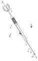
- Fig. 1 is a perspective view of a microwave ablation device in accordance with an embodiment of the present disclosure
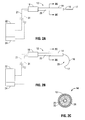
- Figs. 2A and 2B are schematic views of the microwave ablation device of Fig. 1 connected to a generator according to various embodiments of the present disclosure
- Fig. 2C is a cross-sectional view taken along section line 2C-2C of Figs. 2A and 2B ;
- Figs. 3A and 3B are enlarged side views of the microwave ablation device of Fig. 1 according to various embodiments of the present disclosure.
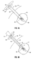
- Figs. 4A and 4B are perspective views of an introducer for use with the microwave ablation device of Fig. 1 .
- proximal will refer to the portion of a structure that is closer to a user
- distal will refer to the portion of the structure that is farther from the user.
- the present disclosure relates to the use of an ablation device having an integrated imaging device, such as an ultrasound transducer adapted to generate image data by generating sound waves within the ultrasound frequency range toward a desired imaging site and subsequently receiving echoing of such sound waves from the desired imaging site.
- an integrated imaging device such as an ultrasound transducer adapted to generate image data by generating sound waves within the ultrasound frequency range toward a desired imaging site and subsequently receiving echoing of such sound waves from the desired imaging site.
- An ablation device e.g., a microwave ablation device in accordance with the present disclosure is referred to in the figures as reference numeral 10. While a microwave ablation device is described herein, it is contemplated that the present disclosure may also be used in connection with other types of ablation devices and other instruments, such as introducers. Such ablation devices may include an antenna and/or an electrode.
- ablation device 10 includes an antenna 12 and a handle portion 13.
- Antenna 12 includes a shaft or feedline 14 having an inner conductor 16 and an outer conductor 20, which defines a longitudinal axis X-X.
- Outer conductor 20 may be, for example, an introducing structure (e.g., needle) configured to pierce and/or penetrate tissue.
- a power transmission cord 21 is shown and connects ablation device 10 to a suitable electrosurgical generator 22 (see Figs. 2A and 2B ). Additionally, an actuation element 7 is illustrated in Fig. 1 in accordance with various embodiments of the present disclosure.
- Actuation element 7 is operably coupled to inner conductor 16 and movable along a track 9 disposed at least partially along the length of handle portion 13 to move inner conductor 16 relative to outer conductor 20. More specifically, distal actuation of actuation element 7 along track 9 deploys or extends inner conductor 16 from outer conductor 20 and proximal actuation of actuation element 7 along track 9 retracts inner conductor 16 within outer conductor 20.
- inner conductor 16 includes a distal tip 17 and is extendable from outer conductor 20.
- inner conductors 16 may be used in connection with the disclosed ablation device 10, including an inner conductor configured to deploy substantially in-line with outer conductor 20 (e.g., Fig. 2A ) and an inner conductor configured to deploy in a curved orientation (e.g., Fig. 2B ) along a curvilinear path to define an ablation region 29.
- a proximal end of feedline 14 includes a coupler 18 that electrically couples antenna 12 to generator 22 via power transmission cord 21.
- distal tip 17 allows for insertion of antenna 12 into tissue with minimal resistance. In those cases where the antenna 12 is inserted into a pre-existing opening, distal tip 17 may be rounded or flat.
- feedline 14 may be in the form of a coaxial cable. Portions of feedline 14 may be formed of outer conductor 20 surrounding inner conductor 16. Each of inner conductor 16 and/or outer conductor 20 may be made of a suitable conductive metal that may be semi-rigid or flexible, such as, for example, copper, gold, or other conductive metals with similar conductivity values. Alternatively, portions of each inner conductor 16 and outer conductor 20 may also be made from stainless steel that may additionally be plated with other materials, e.g., other conductive materials, to improve conductivity or decrease energy loss.
- feedline 14 of antenna 12 is shown including a dielectric material 28 surrounding at least a portion of a length of inner conductor 16 and outer conductor 20 surrounding at least a portion of a length of dielectric material 28 and/or inner conductor 16. That is, dielectric material 28 is interposed between inner conductor 16 and outer conductor 20, to provide insulation therebetween and is comprised of any suitable dielectric material.
- antenna 12 may be embodied having a straight probe configuration of radiating portion 12, as shown in Fig. 3A , or a loop probe configuration of radiating portion 12, as shown in Fig. 3B .
- radiating portion 12 includes a lumen 26 defined coaxially therethrough and at least partially along the length thereof.
- an imaging device 30 Disposed within lumen 26 is an imaging device 30 adapted to image a desired ablation area.
- An electrical lead 31 electrically connects imaging device 30 to a processing unit 24 configured to process data generated by imaging device 30 for representation on a display (see, e.g., Figs 2A, 2B ).
- processing unit 24 may include a processor operably coupled with a memory (not shown) that stores suitable image processing software executable as programmable instructions by the processor to cause processing unit 24 to generate an image based on imaging data received from imaging device 30.
- processing unit 24 may be a stand-alone device or may be incorporated within generator 22.
- Imaging device 30 may be, for example, an ultrasound transducer adapted to generate and receive sound waves to generate imaging data corresponding to the tissue area surrounding radiating portion 12.
- imaging device 30 may be, for example, a CAT scan device, a PET scan device, an X-ray device, an MRI device, or other tomographic or X-ray device utilized to generate imaging data corresponding to the desired ablation area.
- Imaging device 30 may be fixedly mounted within lumen 26 (e.g., via adhesive, fastener, etc.) or may be slidably disposed within lumen 26 such that imaging device 30 may be moved proximally and distally within lumen 26 and/or rotated about longitudinal axis X-X of radiating portion 12 to facilitate 360 degree and/or radial imaging of surrounding tissue along the entire length of inner conductor 16.
- This configuration of imaging device 30 makes three-dimensional imaging of the desired tissue site possible.
- ablation device 10 may also by rotated 360 degrees by the user to achieve three-dimensional imaging of the desired tissue site.
- imaging device 30 may be used in conjunction with an introducer 50 to facilitate placement of radiating portion 12 relative to an ablation area or a tumor "T".
- Introducer 50 includes a shaft 52 extending from a proximal hub 54 to a distal end 58, and a lumen 56 disposed coaxially through shaft 52 from proximal hub 54 distally toward distal end 58 through at least a portion of the length of shaft 52.
- Distal end 58 may be tapered to allow for insertion of introducer 50 into tissue with minimal resistance.
- Shaft 52 is inserted into tissue of a patient "P" until distal portion 58 of shaft 52 is positioned adjacent to or within an ablation area of tissue, e.g., tumor "T", as shown in Figs. 4A and 4B .
- Imaging device 30 is utilized to image the area surrounding distal portion 58 of shaft 52 to ensure that introducer 50 is properly placed relative to the ablation area. More specifically, imaging data relating to the ablation area is received and processed by processing unit 24 for viewing by the surgeon. Based on the generated imaging data, the user may maneuver or re-position the introducer 50 within the patient "P", if necessary, to ensure accurate position of distal portion 58 of shaft 52 relative to tumor "T" before ablation thereof. As illustrated by rotational arrow "A" of Fig. 4A , introducer 50 may be rotated about the longitudinal axis of shaft 52 such that imaging device 30 may be rotated 360 degrees to completely image the ablation area.
- ablation device 10 may then be inserted within lumen 56 while maintaining the position and orientation of shaft 52 within patient "P".
- Ablation device 10 is advanced distally within lumen 56 such that radiating portion 12 of device 10 is adjacent to or within tumor "T".
- the length of radiating portion 12 may be configured to fit within shaft 52 such that a proximal end of handle portion 13 and proximal hub 54 contact one another in a lock-fit manner (not explicitly shown).
- the ablation area may be imaged to enable the user to monitor the progress and/or completeness of the ablation.
- imaging device 30 is shown without electrical lead 31 to illustrate that imaging device 30 may be configured to communicate imaging data to processing unit 24 wirelessly from within patient "P".
- an electrical lead e.g., lead 31
- imaging device 30 may not be necessary to effect proper and intended implementation of any of the embodiments disclosed herein.
- energy generated by generator 22 in close proximity to imaging device 30 may cause interference with image data generated by imaging device 30 during an imaging procedure.
- imaging device 30 and generator 22 may be configured, in certain embodiments, to automatically operate in mutual exclusion relative to one another. More specifically, generator 22 continuously receives and processes an imaging signal generated by imaging device 30 (e.g., wirelessly) and/or processing unit 24 that continuously indicates in real-time whether or not an imaging procedure is currently being performed by imaging device 30. Based on the generated signal, generator 22 terminates energy output during an imaging procedure and continues energy output while no imaging procedure is being performed by the imaging device 30. In this manner, imaging procedures and electrosurgical procedures (e.g., microwave ablation) may be performed in close proximity and essentially during the same procedure or operation without adverse effects (e.g., image distortion) to the imaging process caused by interference from the output of generator 22.
- adverse effects e.g., image distortion
- imaging device 30 and/or processing unit 24 include suitable circuitry (e.g., processor, memory, a/d converter, etc.) configured to generate the imaging signal as output and, further, that generator 22 includes suitable circuitry configured to receive and process the imaging signal as input.
- processing unit 24 and/or ablation device 10 may include buttons, switches, actuators, or the like, configured to activate or deactivate imaging device 30 and/or to generate a signal to generator 22 indicating the activation, suspension, and/or termination of an imaging procedure.
Abstract
Description
- The present disclosure relates to energy-based apparatuses, systems and methods. More particularly, the present disclosure is directed to a system and method for performing an electrosurgical procedure using an ablation system including an integrated imaging device.
- In the treatment of diseases such as cancer, certain types of cancer cells have been found to denature at elevated temperatures (which are slightly lower than temperatures normally injurious to healthy cells.) These types of treatments, known generally as hyperthermia therapy, typically utilize electromagnetic radiation to heat diseased cells to temperatures above 41°C, while maintaining adjacent healthy cells at lower temperatures where irreversible cell destruction will not occur. Other procedures utilizing electromagnetic radiation to heat tissue also include ablation and coagulation of the tissue. Such microwave ablation procedures, e.g., such as those performed for menorrhagia, are typically done to ablate and coagulate the targeted tissue to denature or kill the tissue. Many procedures and types of devices utilizing electromagnetic radiation therapy are known in the art. Such microwave therapy is typically used in the treatment of tissue and organs such as the prostate, heart, liver, lung, kidney, and breast.
- One non-invasive procedure generally involves the treatment of tissue (e.g., a tumor) underlying the skin via the use of microwave energy. The microwave energy is able to non-invasively penetrate the skin to reach the underlying tissue. However, this non-invasive procedure may result in the unwanted heating of healthy tissue. Thus, the non-invasive use of microwave energy requires a great deal of control.
- Presently, there are several types of microwave probes in use, e.g., monopole, dipole, and helical. One type is a monopole antenna probe, which consists of a single, elongated microwave conductor exposed at the end of the probe. The probe is typically surrounded by a dielectric sleeve. The second type of microwave probe commonly used is a dipole antenna, which consists of a coaxial construction having an inner conductor and an outer conductor with a dielectric junction separating a portion of the inner conductor. The inner conductor may be coupled to a portion corresponding to a first dipole radiating portion, and a portion of the outer conductor may be coupled to a second dipole radiating portion. The dipole radiating portions may be configured such that one radiating portion is located proximally of the dielectric junction, and the other portion is located distally of the dielectric junction. In the monopole and dipole antenna probe, microwave energy generally radiates perpendicularly from the axis of the conductor.
- The typical microwave antenna has a long, thin inner conductor that extends along the axis of the probe and is surrounded by a dielectric material and is further surrounded by an outer conductor around the dielectric material such that the outer conductor also extends along the axis of the probe. In another variation of the probe that provides for effective outward radiation of energy or heating, a portion or portions of the outer conductor can be selectively removed. This type of construction is typically referred to as a "leaky waveguide" or "leaky coaxial" antenna. Another variation on the microwave probe involves having the tip formed in a uniform spiral pattern, such as a helix, to provide the necessary configuration for effective radiation. This variation can be used to direct energy in a particular direction, e.g., perpendicular to the axis, in a forward direction (i.e., towards the distal end of the antenna), or combinations thereof.
- Invasive procedures and devices have been developed in which a microwave antenna probe may be either inserted directly into a point of treatment via a normal body orifice or percutaneously inserted. Such invasive procedures and devices potentially provide better temperature control of the tissue being treated. Because of the small difference between the temperature required for denaturing malignant cells and the temperature injurious to healthy cells, a known heating pattern and predictable temperature control is important so that heating is confined to the tissue to be treated. For instance, hyperthermia treatment at the threshold temperature of about 41.5°C generally has little effect on most malignant growth of cells. However, at slightly elevated temperatures above the approximate range of 43°C to 45°C, thermal damage to most types of normal cells is routinely observed. Accordingly, great care must be taken not to exceed these temperatures in healthy tissue.
- In the case of tissue ablation, a high radio frequency electrical current in the range of about 500 mHz to about 10 gHz is applied to a targeted tissue site to create an ablation volume, which may have a particular size and shape. The targeted tissue site is observed prior to the application of energy thereto to ensure accurate placement of the ablation device (e.g., microwave antenna) relative to the targeted tissue site. Typically, observation is facilitated through scanned data obtained through use of imaging devices such as CT, MRI, PET, or other tomographic or X-ray devices. However, images obtained using such scanning techniques before, during, or after an electrosurgical procedure, such as tissue ablation, are obtained from outside the patient and, therefore, are often lacking in quality due to distortions and the limitations of two-dimensional imaging.
- According to an embodiment of the present disclosure, an ablation device includes an antenna assembly having a radiating portion configured to deliver energy from a power source to tissue of a patient. The radiating portion has an outer conductor and an inner conductor. The inner conductor is disposed within the outer conductor. The device also includes an imaging device operably coupled to the inner conductor. The imaging device is configured to generate imaging data corresponding to tissue proximate the radiating portion of the antenna assembly.
- According to another embodiment of the present disclosure, a microwave ablation system includes an antenna assembly configured to deliver energy from a power source to tissue of a patient and an introducer having a distal end configured to penetrate tissue. The introducer has a lumen disposed coaxially therein at least partially along its length. The lumen is configured to receive the antenna assembly therein. The system also includes an imaging device disposed on the introducer configured to provide imaging data to a processing unit corresponding to tissue proximate the introducer. The processing unit is configured to generate an image based on the imaging data.
- According to another embodiment of the present disclosure, a method for performing an electrosurgical procedure includes the steps of positioning an ablation device including an imaging device proximate a desired tissue site of a patient and imaging the desired tissue site to generate corresponding imaging data. The method also includes the steps of generating a display of the desired tissue site based on the imaging data and re-positioning the ablation device proximate the desired tissue site based on the display. The method also includes the step of supplying energy from an energy source to the ablation device for application to the desired tissue site.
- Various embodiments of the present disclosure are described herein with reference to the drawings wherein:
-
Fig. 1 is a perspective view of a microwave ablation device in accordance with an embodiment of the present disclosure; -
Figs. 2A and 2B are schematic views of the microwave ablation device ofFig. 1 connected to a generator according to various embodiments of the present disclosure; -
Fig. 2C is a cross-sectional view taken alongsection line 2C-2C ofFigs. 2A and 2B ; -
Figs. 3A and 3B are enlarged side views of the microwave ablation device ofFig. 1 according to various embodiments of the present disclosure; and -
Figs. 4A and 4B are perspective views of an introducer for use with the microwave ablation device ofFig. 1 . - Particular embodiments of the present disclosure are described hereinbelow with reference to the accompanying drawings. In the following description, well-known functions or constructions are not described in detail to avoid obscuring the present disclosure in unnecessary detail. In the discussion that follows, the term "proximal" will refer to the portion of a structure that is closer to a user, while the term "distal" will refer to the portion of the structure that is farther from the user.
- Generally, the present disclosure relates to the use of an ablation device having an integrated imaging device, such as an ultrasound transducer adapted to generate image data by generating sound waves within the ultrasound frequency range toward a desired imaging site and subsequently receiving echoing of such sound waves from the desired imaging site. The ability to radially visualize target tissue before, during, and/or after an ablation procedure in three dimensions allows a user to accurately place the ablation device within the target tissue and, further, to monitor ablation progress.
- An ablation device (e.g., a microwave ablation device) in accordance with the present disclosure is referred to in the figures as
reference numeral 10. While a microwave ablation device is described herein, it is contemplated that the present disclosure may also be used in connection with other types of ablation devices and other instruments, such as introducers. Such ablation devices may include an antenna and/or an electrode. - Referring initially to
Fig. 1 ,ablation device 10 includes anantenna 12 and ahandle portion 13.Antenna 12 includes a shaft orfeedline 14 having aninner conductor 16 and anouter conductor 20, which defines a longitudinal axis X-X.Outer conductor 20 may be, for example, an introducing structure (e.g., needle) configured to pierce and/or penetrate tissue. Apower transmission cord 21 is shown and connectsablation device 10 to a suitable electrosurgical generator 22 (seeFigs. 2A and 2B ). Additionally, anactuation element 7 is illustrated inFig. 1 in accordance with various embodiments of the present disclosure.Actuation element 7 is operably coupled toinner conductor 16 and movable along a track 9 disposed at least partially along the length ofhandle portion 13 to moveinner conductor 16 relative toouter conductor 20. More specifically, distal actuation ofactuation element 7 along track 9 deploys or extendsinner conductor 16 fromouter conductor 20 and proximal actuation ofactuation element 7 along track 9 retractsinner conductor 16 withinouter conductor 20. - As seen in
Fig. 2A ,inner conductor 16 includes adistal tip 17 and is extendable fromouter conductor 20. Several types ofinner conductors 16 may be used in connection with the disclosedablation device 10, including an inner conductor configured to deploy substantially in-line with outer conductor 20 (e.g.,Fig. 2A ) and an inner conductor configured to deploy in a curved orientation (e.g.,Fig. 2B ) along a curvilinear path to define anablation region 29. In the illustrated embodiments ofFigs. 2A and 2B , a proximal end offeedline 14 includes acoupler 18 that electrically couplesantenna 12 togenerator 22 viapower transmission cord 21. - In some embodiments,
distal tip 17 allows for insertion ofantenna 12 into tissue with minimal resistance. In those cases where theantenna 12 is inserted into a pre-existing opening,distal tip 17 may be rounded or flat. - As shown in
Fig. 2C ,feedline 14 may be in the form of a coaxial cable. Portions offeedline 14 may be formed ofouter conductor 20 surroundinginner conductor 16. Each ofinner conductor 16 and/orouter conductor 20 may be made of a suitable conductive metal that may be semi-rigid or flexible, such as, for example, copper, gold, or other conductive metals with similar conductivity values. Alternatively, portions of eachinner conductor 16 andouter conductor 20 may also be made from stainless steel that may additionally be plated with other materials, e.g., other conductive materials, to improve conductivity or decrease energy loss. - With continued reference to
Fig. 2C ,feedline 14 ofantenna 12 is shown including adielectric material 28 surrounding at least a portion of a length ofinner conductor 16 andouter conductor 20 surrounding at least a portion of a length ofdielectric material 28 and/orinner conductor 16. That is,dielectric material 28 is interposed betweeninner conductor 16 andouter conductor 20, to provide insulation therebetween and is comprised of any suitable dielectric material. - With reference to
Figs. 3A and 3B ,antenna 12 may be embodied having a straight probe configuration of radiatingportion 12, as shown inFig. 3A , or a loop probe configuration of radiatingportion 12, as shown inFig. 3B . In either scenario, radiatingportion 12 includes alumen 26 defined coaxially therethrough and at least partially along the length thereof. Disposed withinlumen 26 is animaging device 30 adapted to image a desired ablation area. Anelectrical lead 31 electrically connectsimaging device 30 to aprocessing unit 24 configured to process data generated by imagingdevice 30 for representation on a display (see, e.g.,Figs 2A, 2B ). Although not shown entirely in the accompanying figures, lead 31 is connected to processingunit 24 and extends therefrom throughhandle assembly 13 andlumen 26 to connect toimaging device 30. Processingunit 24 may include a processor operably coupled with a memory (not shown) that stores suitable image processing software executable as programmable instructions by the processor to causeprocessing unit 24 to generate an image based on imaging data received fromimaging device 30. Processingunit 24 may be a stand-alone device or may be incorporated withingenerator 22.Imaging device 30 may be, for example, an ultrasound transducer adapted to generate and receive sound waves to generate imaging data corresponding to the tissue area surrounding radiatingportion 12. In other embodiments,imaging device 30 may be, for example, a CAT scan device, a PET scan device, an X-ray device, an MRI device, or other tomographic or X-ray device utilized to generate imaging data corresponding to the desired ablation area. -
Imaging device 30 may be fixedly mounted within lumen 26 (e.g., via adhesive, fastener, etc.) or may be slidably disposed withinlumen 26 such thatimaging device 30 may be moved proximally and distally withinlumen 26 and/or rotated about longitudinal axis X-X of radiatingportion 12 to facilitate 360 degree and/or radial imaging of surrounding tissue along the entire length ofinner conductor 16. This configuration ofimaging device 30 makes three-dimensional imaging of the desired tissue site possible. With this purpose in mind,ablation device 10 may also by rotated 360 degrees by the user to achieve three-dimensional imaging of the desired tissue site. - In another embodiment shown in
Figs. 4A and 4B ,imaging device 30 may be used in conjunction with anintroducer 50 to facilitate placement of radiatingportion 12 relative to an ablation area or a tumor "T".Introducer 50 includes ashaft 52 extending from aproximal hub 54 to adistal end 58, and alumen 56 disposed coaxially throughshaft 52 fromproximal hub 54 distally towarddistal end 58 through at least a portion of the length ofshaft 52.Distal end 58 may be tapered to allow for insertion ofintroducer 50 into tissue with minimal resistance.Shaft 52 is inserted into tissue of a patient "P" untildistal portion 58 ofshaft 52 is positioned adjacent to or within an ablation area of tissue, e.g., tumor "T", as shown inFigs. 4A and 4B .Imaging device 30 is utilized to image the area surroundingdistal portion 58 ofshaft 52 to ensure thatintroducer 50 is properly placed relative to the ablation area. More specifically, imaging data relating to the ablation area is received and processed by processingunit 24 for viewing by the surgeon. Based on the generated imaging data, the user may maneuver or re-position theintroducer 50 within the patient "P", if necessary, to ensure accurate position ofdistal portion 58 ofshaft 52 relative to tumor "T" before ablation thereof. As illustrated by rotational arrow "A" ofFig. 4A ,introducer 50 may be rotated about the longitudinal axis ofshaft 52 such thatimaging device 30 may be rotated 360 degrees to completely image the ablation area. - Once
introducer 50 is desirably positioned,ablation device 10 may then be inserted withinlumen 56 while maintaining the position and orientation ofshaft 52 within patient "P".Ablation device 10 is advanced distally withinlumen 56 such that radiatingportion 12 ofdevice 10 is adjacent to or within tumor "T". The length of radiatingportion 12 may be configured to fit withinshaft 52 such that a proximal end ofhandle portion 13 andproximal hub 54 contact one another in a lock-fit manner (not explicitly shown). During and/or after an ablation procedure, the ablation area may be imaged to enable the user to monitor the progress and/or completeness of the ablation. - In the illustrated embodiment of
Figs. 4A and 4B ,imaging device 30 is shown withoutelectrical lead 31 to illustrate thatimaging device 30 may be configured to communicate imaging data to processingunit 24 wirelessly from within patient "P". As such, an electrical lead (e.g., lead 31) connectingimaging device 30 toprocessing unit 24 may not be necessary to effect proper and intended implementation of any of the embodiments disclosed herein. - In use, energy (e.g., microwave energy) generated by
generator 22 in close proximity toimaging device 30 may cause interference with image data generated by imagingdevice 30 during an imaging procedure. In this scenario,imaging device 30 andgenerator 22 may be configured, in certain embodiments, to automatically operate in mutual exclusion relative to one another. More specifically,generator 22 continuously receives and processes an imaging signal generated by imaging device 30 (e.g., wirelessly) and/orprocessing unit 24 that continuously indicates in real-time whether or not an imaging procedure is currently being performed byimaging device 30. Based on the generated signal,generator 22 terminates energy output during an imaging procedure and continues energy output while no imaging procedure is being performed by theimaging device 30. In this manner, imaging procedures and electrosurgical procedures (e.g., microwave ablation) may be performed in close proximity and essentially during the same procedure or operation without adverse effects (e.g., image distortion) to the imaging process caused by interference from the output ofgenerator 22. - Those skilled in the art will appreciate that
imaging device 30 and/orprocessing unit 24 include suitable circuitry (e.g., processor, memory, a/d converter, etc.) configured to generate the imaging signal as output and, further, thatgenerator 22 includes suitable circuitry configured to receive and process the imaging signal as input. In some embodiments, processingunit 24 and/orablation device 10 may include buttons, switches, actuators, or the like, configured to activate or deactivateimaging device 30 and/or to generate a signal togenerator 22 indicating the activation, suspension, and/or termination of an imaging procedure. - While several embodiments of the disclosure have been shown in the drawings and/or discussed herein, it is not intended that the disclosure be limited thereto, as it is intended that the disclosure be as broad in scope as the art will allow and that the specification be read likewise. Therefore, the above description should not be construed as limiting, but merely as exemplifications of particular embodiments. For example, it should be understood that any of the above disclosed embodiments may be configured such that
imaging device 50 generates a logic low to indicate an imaging procedure is currently being performed and, vice-versa, a logic high may indicate that no imaging procedure is currently being performed. Those skilled in the art will envision other modifications within the scope and spirit of the claims appended hereto.
Claims (14)
- An ablation device, comprising:an antenna assembly having a radiating portion configured to deliver energy from a power source to tissue of a patient; andan imaging device coupled to the radiating portion and configured to generate imaging data corresponding to the tissue.
- An ablation device according to claim 1, wherein the radiating portion includes outer conductor and an inner conductor extending therethrough, the inner conductor disposed within the outer conductor.
- An ablation device according to claim 2, wherein the inner conductor is configured to deploy from the outer conductor into the tissue.
- An ablation device according to claim 1, wherein the imaging device is selected from the group consisting of ultrasound transducers, CAT scan devices, MRI devices, and PET scan devices.
- An ablation device according to claim 1, wherein the imaging device is movable relative to the radiating portion to generate three-dimensional image data of tissue surrounding the radiating portion.
- An ablation device according to claim 1, wherein a lumen is defined coaxially through at least a portion of the radiating portion, the imaging device disposed within the lumen.
- An ablation device according to claim 1, wherein the imaging device is configured to communicate the imaging data to a processing unit adapted to generate a display based on the imaging data.
- An ablation device according to claim 7, wherein the imaging device is configured to communicate the imaging data to the processing unit wirelessly.
- An ablation device according to claim 1, wherein the antenna assembly includes a straight probe configuration.
- An ablation device according to claim 1, wherein the antenna assembly includes a loop probe configuration configured to deploy in a curved orientation along a curvilinear path to define an ablation area.
- A microwave ablation system, comprising:an antenna assembly configured to deliver energy from a power source to tissue of a patient;an introducer having a distal end configured to penetrate tissue and having a lumen disposed coaxially therein at least partially along the length thereof and configured to receive the antenna assembly therein; andan imaging device disposed on the introducer and configured to provide imaging data to a processing unit corresponding to tissue proximate the introducer.
- A microwave ablation system according to claim 11, wherein the imaging device is selected from the group consisting of ultrasound transducers, CAT scan devices, MRI devices, and PET scan devices.
- A microwave ablation system according to claim 11, wherein the introducer is placed relative to the tissue based on the imaging data.
- A microwave ablation system according to claim 11, wherein the introducer is rotatable 360° about a longitudinal axis thereof to facilitate radial imaging of tissue proximate the introducer.
Priority Applications (2)
| Application Number | Priority Date | Filing Date | Title |
|---|---|---|---|
| EP15202131.7A EP3025664A1 (en) | 2010-01-29 | 2011-01-27 | System for performing an electrosurgical procedure using an ablation device with an integrated imaging device |
| EP13003544.7A EP2664358B1 (en) | 2010-01-29 | 2011-01-27 | Microwave ablation device with an integrated imaging device |
Applications Claiming Priority (1)
| Application Number | Priority Date | Filing Date | Title |
|---|---|---|---|
| US12/696,966 US8313486B2 (en) | 2010-01-29 | 2010-01-29 | System and method for performing an electrosurgical procedure using an ablation device with an integrated imaging device |
Related Child Applications (3)
| Application Number | Title | Priority Date | Filing Date |
|---|---|---|---|
| EP13003544.7A Division EP2664358B1 (en) | 2010-01-29 | 2011-01-27 | Microwave ablation device with an integrated imaging device |
| EP15202131.7A Division EP3025664A1 (en) | 2010-01-29 | 2011-01-27 | System for performing an electrosurgical procedure using an ablation device with an integrated imaging device |
| EP13003544.7 Division-Into | 2013-07-13 |
Publications (2)
| Publication Number | Publication Date |
|---|---|
| EP2359902A1 true EP2359902A1 (en) | 2011-08-24 |
| EP2359902B1 EP2359902B1 (en) | 2013-09-18 |
Family
ID=44123417
Family Applications (3)
| Application Number | Title | Priority Date | Filing Date |
|---|---|---|---|
| EP11000669.9A Active EP2359902B1 (en) | 2010-01-29 | 2011-01-27 | System for performing an electrosurgical procedure using an ablation device with an integrated imaging device |
| EP13003544.7A Not-in-force EP2664358B1 (en) | 2010-01-29 | 2011-01-27 | Microwave ablation device with an integrated imaging device |
| EP15202131.7A Withdrawn EP3025664A1 (en) | 2010-01-29 | 2011-01-27 | System for performing an electrosurgical procedure using an ablation device with an integrated imaging device |
Family Applications After (2)
| Application Number | Title | Priority Date | Filing Date |
|---|---|---|---|
| EP13003544.7A Not-in-force EP2664358B1 (en) | 2010-01-29 | 2011-01-27 | Microwave ablation device with an integrated imaging device |
| EP15202131.7A Withdrawn EP3025664A1 (en) | 2010-01-29 | 2011-01-27 | System for performing an electrosurgical procedure using an ablation device with an integrated imaging device |
Country Status (5)
| Country | Link |
|---|---|
| US (4) | US8313486B2 (en) |
| EP (3) | EP2359902B1 (en) |
| JP (2) | JP5984334B2 (en) |
| AU (1) | AU2011200329B2 (en) |
| CA (2) | CA2729363C (en) |
Families Citing this family (34)
| Publication number | Priority date | Publication date | Assignee | Title |
|---|---|---|---|---|
| US8361067B2 (en) | 2002-09-30 | 2013-01-29 | Relievant Medsystems, Inc. | Methods of therapeutically heating a vertebral body to treat back pain |
| US6907884B2 (en) | 2002-09-30 | 2005-06-21 | Depay Acromed, Inc. | Method of straddling an intraosseous nerve |
| US7258690B2 (en) | 2003-03-28 | 2007-08-21 | Relievant Medsystems, Inc. | Windowed thermal ablation probe |
| US7553309B2 (en) | 2004-10-08 | 2009-06-30 | Covidien Ag | Electrosurgical system employing multiple electrodes and method thereof |
| US8292880B2 (en) | 2007-11-27 | 2012-10-23 | Vivant Medical, Inc. | Targeted cooling of deployable microwave antenna |
| US8353902B2 (en) | 2008-01-31 | 2013-01-15 | Vivant Medical, Inc. | Articulating ablation device and method |
| US10028753B2 (en) | 2008-09-26 | 2018-07-24 | Relievant Medsystems, Inc. | Spine treatment kits |
| AU2009296474B2 (en) | 2008-09-26 | 2015-07-02 | Relievant Medsystems, Inc. | Systems and methods for navigating an instrument through bone |
| US8292881B2 (en) | 2009-05-27 | 2012-10-23 | Vivant Medical, Inc. | Narrow gauge high strength choked wet tip microwave ablation antenna |
| US8313486B2 (en) | 2010-01-29 | 2012-11-20 | Vivant Medical, Inc. | System and method for performing an electrosurgical procedure using an ablation device with an integrated imaging device |
| US8728067B2 (en) | 2010-03-08 | 2014-05-20 | Covidien Lp | Microwave antenna probe having a deployable ground plane |
| US8409188B2 (en) | 2010-03-26 | 2013-04-02 | Covidien Lp | Ablation devices with adjustable radiating section lengths, electrosurgical systems including same, and methods of adjusting ablation fields using same |
| US9561076B2 (en) | 2010-05-11 | 2017-02-07 | Covidien Lp | Electrosurgical devices with balun structure for air exposure of antenna radiating section and method of directing energy to tissue using same |
| US9192436B2 (en) | 2010-05-25 | 2015-11-24 | Covidien Lp | Flow rate verification monitor for fluid-cooled microwave ablation probe |
| US8652127B2 (en) | 2010-05-26 | 2014-02-18 | Covidien Lp | System and method for chemically cooling an ablation antenna |
| US9241762B2 (en) | 2010-06-03 | 2016-01-26 | Covidien Lp | Specific absorption rate measurement and energy-delivery device characterization using image analysis |
| US8672933B2 (en) | 2010-06-30 | 2014-03-18 | Covidien Lp | Microwave antenna having a reactively-loaded loop configuration |
| US9055957B2 (en) | 2010-12-23 | 2015-06-16 | Covidien Lp | Microwave field-detecting needle assemblies, methods of manufacturing same, methods of adjusting an ablation field radiating into tissue using same, and systems including same |
| US9770294B2 (en) | 2011-01-05 | 2017-09-26 | Covidien Lp | Energy-delivery devices with flexible fluid-cooled shaft, inflow/outflow junctions suitable for use with same, and systems including same |
| US9028476B2 (en) | 2011-02-03 | 2015-05-12 | Covidien Lp | Dual antenna microwave resection and ablation device, system and method of use |
| US10335230B2 (en) | 2011-03-09 | 2019-07-02 | Covidien Lp | Systems for thermal-feedback-controlled rate of fluid flow to fluid-cooled antenna assembly and methods of directing energy to tissue using same |
| WO2013101772A1 (en) | 2011-12-30 | 2013-07-04 | Relievant Medsystems, Inc. | Systems and methods for treating back pain |
| GB2514714A (en) * | 2012-03-29 | 2014-12-03 | Spiration Inc | Apparatuses, methods, and systems for the identification and treatment of pulmonary tissue |
| US10588691B2 (en) | 2012-09-12 | 2020-03-17 | Relievant Medsystems, Inc. | Radiofrequency ablation of tissue within a vertebral body |
| EP2914186B1 (en) | 2012-11-05 | 2019-03-13 | Relievant Medsystems, Inc. | Systems for creating curved paths through bone and modulating nerves within the bone |
| JP6392864B2 (en) | 2013-07-03 | 2018-09-19 | コーニンクレッカ フィリップス エヌ ヴェKoninklijke Philips N.V. | Temperature distribution determination device |
| US9724151B2 (en) | 2013-08-08 | 2017-08-08 | Relievant Medsystems, Inc. | Modulating nerves within bone using bone fasteners |
| WO2017040155A1 (en) * | 2015-09-01 | 2017-03-09 | The Government Of The United States Of America, As Represented By The Secretary Of The Navy | Miniature acoustic leaky-wave antenna for ultrasonic imaging |
| GB2545465A (en) * | 2015-12-17 | 2017-06-21 | Creo Medical Ltd | Electrosurgical probe for delivering microwave energy |
| US10524875B2 (en) | 2016-04-14 | 2020-01-07 | Focal Therapeutics Inc. | Tissue localization device and method of use thereof |
| KR101797910B1 (en) * | 2016-04-18 | 2017-11-15 | 한국지이초음파 유한회사 | Rotatory linear probe |
| DE102017130526A1 (en) | 2017-12-19 | 2019-06-19 | Medizinische Hochschule Hannover | Needle-shaped applicator |
| GB2575984B (en) * | 2018-07-30 | 2022-09-14 | Creo Medical Ltd | Electrosurgical instrument |
| CA3150339A1 (en) | 2019-09-12 | 2021-03-18 | Brian W. Donovan | Systems and methods for tissue modulation |
Citations (10)
| Publication number | Priority date | Publication date | Assignee | Title |
|---|---|---|---|---|
| US5861002A (en) * | 1991-10-18 | 1999-01-19 | Desai; Ashvin H. | Endoscopic surgical instrument |
| EP0893101A2 (en) * | 1992-08-12 | 1999-01-27 | Vidamed, Inc. | Medical probe device and method |
| WO2001064121A1 (en) * | 2000-02-29 | 2001-09-07 | Boston Scientific Limited | Rf ablation and ultrasound catheter for crossing chronic total occlusions |
| US20040147917A1 (en) * | 2003-01-23 | 2004-07-29 | Mueller Richard L. | Device and method for treatment of breast tissue with electromagnetic radiation |
| US20080243162A1 (en) * | 2007-04-02 | 2008-10-02 | Norikiyo Shibata | Trocar |
| US20080287801A1 (en) * | 2006-08-14 | 2008-11-20 | Novelis, Inc. | Imaging device, imaging system, and methods of imaging |
| WO2008144341A1 (en) * | 2007-05-15 | 2008-11-27 | Gynesonics, Inc | Systems and methods for deploying echogenic components in ultrasonic imaging fields |
| US20090076375A1 (en) * | 2007-09-13 | 2009-03-19 | Siemens Aktiengesellschaft | Myocardial tissue ablation device for treatment of cardiac arrhythmias by ablation of myocardial tissue in a patient as well as associated catheter and associated method |
| US20090088648A1 (en) * | 2007-06-18 | 2009-04-02 | Ronen Jaffe | Methods and devices for image-guided manipulation or sensing or anatomic structures |
| US20090299360A1 (en) * | 2008-05-28 | 2009-12-03 | Medwaves, Inc. | Tissue ablation apparatus and method using ultrasonic imaging |
Family Cites Families (148)
| Publication number | Priority date | Publication date | Assignee | Title |
|---|---|---|---|---|
| DE439049C (en) | 1926-12-31 | Walter Eichelberg | Radio reception arrangement | |
| DE390937C (en) | 1922-10-13 | 1924-03-03 | Adolf Erb | Device for internal heating of furnace furnaces for hardening, tempering, annealing, quenching and melting |
| DE1099658B (en) | 1959-04-29 | 1961-02-16 | Siemens Reiniger Werke Ag | Automatic switch-on device for high-frequency surgical devices |
| FR1275415A (en) | 1960-09-26 | 1961-11-10 | Device for detecting disturbances for electrical installations, in particular electrosurgery | |
| DE1139927B (en) | 1961-01-03 | 1962-11-22 | Friedrich Laber | High-frequency surgical device |
| DE1149832C2 (en) | 1961-02-25 | 1977-10-13 | Siemens AG, 1000 Berlin und 8000 München | HIGH FREQUENCY SURGICAL EQUIPMENT |
| FR1347865A (en) | 1962-11-22 | 1964-01-04 | Improvements to diathermo-coagulation devices | |
| DE1439302B2 (en) | 1963-10-26 | 1971-05-19 | Siemens AG, 1000 Berlin u 8000 München | High frequency surgical device |
| SU401367A1 (en) | 1971-10-05 | 1973-10-12 | Тернопольский государственный медицинский институт | BIAKTIVNYE ELECTRO SURGICAL INSTRUMENT |
| FR2235669A1 (en) | 1973-07-07 | 1975-01-31 | Lunacek Boris | Gynaecological sterilisation instrument - has hollow electrode protruding from the end of a curved ended tube |
| GB1480736A (en) | 1973-08-23 | 1977-07-20 | Matburn Ltd | Electrodiathermy apparatus |
| DE2455174A1 (en) | 1973-11-21 | 1975-05-22 | Termiflex Corp | INPUT / OUTPUT DEVICE FOR DATA EXCHANGE WITH DATA PROCESSING DEVICES |
| DE2407559C3 (en) | 1974-02-16 | 1982-01-21 | Dornier System Gmbh, 7990 Friedrichshafen | Heat probe |
| DE2415263A1 (en) | 1974-03-29 | 1975-10-02 | Aesculap Werke Ag | Surgical H.F. coagulation probe has electrode tongs - with exposed ends of insulated conductors forming tong-jaws |
| DE2429021C2 (en) | 1974-06-18 | 1983-12-08 | Erbe Elektromedizin GmbH, 7400 Tübingen | Remote switching device for an HF surgical device |
| FR2276027A1 (en) | 1974-06-25 | 1976-01-23 | Medical Plastics Inc | Plate electrode with connector - is clamped between connector jaws held by releasable locking device |
| DE2460481A1 (en) | 1974-12-20 | 1976-06-24 | Delma Elektro Med App | Electrode grip for remote HF surgical instrument switching - has shaped insulated piece with contact ring of sterilizable (silicon) rubber |
| US4237887A (en) | 1975-01-23 | 1980-12-09 | Valleylab, Inc. | Electrosurgical device |
| DE2504280C3 (en) | 1975-02-01 | 1980-08-28 | Hans Heinrich Prof. Dr. 8035 Gauting Meinke | Device for cutting and / or coagulating human tissue with high frequency current |
| CA1064581A (en) | 1975-06-02 | 1979-10-16 | Stephen W. Andrews | Pulse control circuit and method for electrosurgical units |
| FR2315286A2 (en) | 1975-06-26 | 1977-01-21 | Lamidey Marcel | H.F. blood coagulating dissecting forceps - with adjustable stops to vary clamping space and circuit making contacts |
| DE2540968C2 (en) | 1975-09-13 | 1982-12-30 | Erbe Elektromedizin GmbH, 7400 Tübingen | Device for switching on the coagulation current of a bipolar coagulation forceps |
| FR2390968A1 (en) | 1977-05-16 | 1978-12-15 | Skovajsa Joseph | Local acupuncture treatment appts. - has oblong head with end aperture and contains laser diode unit (NL 20.11.78) |
| SU727201A2 (en) | 1977-11-02 | 1980-04-15 | Киевский Научно-Исследовательский Институт Нейрохирургии | Electric surgical apparatus |
| DE2803275C3 (en) | 1978-01-26 | 1980-09-25 | Aesculap-Werke Ag Vormals Jetter & Scheerer, 7200 Tuttlingen | Remote switching device for switching a monopolar HF surgical device |
| DE2823291A1 (en) | 1978-05-27 | 1979-11-29 | Rainer Ing Grad Koch | Coagulation instrument automatic HF switching circuit - has first lead to potentiometer and second to transistor base |
| DE2946728A1 (en) | 1979-11-20 | 1981-05-27 | Erbe Elektromedizin GmbH & Co KG, 7400 Tübingen | HF surgical appts. for use with endoscope - provides cutting or coagulation current at preset intervals and of selected duration |
| USD263020S (en) * | 1980-01-22 | 1982-02-16 | Rau Iii David M | Retractable knife |
| JPS5778844A (en) | 1980-11-04 | 1982-05-17 | Kogyo Gijutsuin | Lasre knife |
| DE3045996A1 (en) | 1980-12-05 | 1982-07-08 | Medic Eschmann Handelsgesellschaft für medizinische Instrumente mbH, 2000 Hamburg | Electro-surgical scalpel instrument - has power supply remotely controlled by surgeon |
| FR2502935B1 (en) | 1981-03-31 | 1985-10-04 | Dolley Roger | METHOD AND DEVICE FOR CONTROLLING THE COAGULATION OF TISSUES USING A HIGH FREQUENCY CURRENT |
| DE3120102A1 (en) | 1981-05-20 | 1982-12-09 | F.L. Fischer GmbH & Co, 7800 Freiburg | ARRANGEMENT FOR HIGH-FREQUENCY COAGULATION OF EGG WHITE FOR SURGICAL PURPOSES |
| FR2517953A1 (en) | 1981-12-10 | 1983-06-17 | Alvar Electronic | Diaphanometer for optical examination of breast tissue structure - measures tissue transparency using two plates and optical fibre bundle cooperating with photoelectric cells |
| FR2573301B3 (en) | 1984-11-16 | 1987-04-30 | Lamidey Gilles | SURGICAL PLIERS AND ITS CONTROL AND CONTROL APPARATUS |
| DE3510586A1 (en) | 1985-03-23 | 1986-10-02 | Erbe Elektromedizin GmbH, 7400 Tübingen | Control device for a high-frequency surgical instrument |
| USD295893S (en) * | 1985-09-25 | 1988-05-24 | Acme United Corporation | Disposable surgical clamp |
| USD295894S (en) * | 1985-09-26 | 1988-05-24 | Acme United Corporation | Disposable surgical scissors |
| DE3604823C2 (en) | 1986-02-15 | 1995-06-01 | Lindenmeier Heinz | High frequency generator with automatic power control for high frequency surgery |
| JPH055106Y2 (en) | 1986-02-28 | 1993-02-09 | ||
| EP0246350A1 (en) | 1986-05-23 | 1987-11-25 | Erbe Elektromedizin GmbH. | Coagulation electrode |
| JPH0540112Y2 (en) | 1987-03-03 | 1993-10-12 | ||
| DE3711511C1 (en) | 1987-04-04 | 1988-06-30 | Hartmann & Braun Ag | Method for determining gas concentrations in a gas mixture and sensor for measuring thermal conductivity |
| DE8712328U1 (en) | 1987-09-11 | 1988-02-18 | Jakoubek, Franz, 7201 Emmingen-Liptingen, De | |
| DE3904558C2 (en) | 1989-02-15 | 1997-09-18 | Lindenmeier Heinz | Automatically power-controlled high-frequency generator for high-frequency surgery |
| DE3942998C2 (en) | 1989-12-27 | 1998-11-26 | Delma Elektro Med App | High frequency electrosurgical unit |
| JP2806511B2 (en) | 1990-07-31 | 1998-09-30 | 松下電工株式会社 | Manufacturing method of sintered alloy |
| JP2951418B2 (en) | 1991-02-08 | 1999-09-20 | トキコ株式会社 | Sample liquid component analyzer |
| DE4122050C2 (en) | 1991-07-03 | 1996-05-30 | Gore W L & Ass Gmbh | Antenna arrangement with supply line for medical heat application in body cavities |
| US6730081B1 (en) * | 1991-10-18 | 2004-05-04 | Ashvin H. Desai | Endoscopic surgical instrument |
| DE4238263A1 (en) | 1991-11-15 | 1993-05-19 | Minnesota Mining & Mfg | Adhesive comprising hydrogel and crosslinked polyvinyl:lactam - is used in electrodes for biomedical application providing low impedance and good mechanical properties when water and/or moisture is absorbed from skin |
| DE4205213A1 (en) | 1992-02-20 | 1993-08-26 | Delma Elektro Med App | HIGH FREQUENCY SURGERY DEVICE |
| FR2687786B1 (en) | 1992-02-26 | 1994-05-06 | Pechiney Recherche | MEASUREMENT OF ELECTRICAL RESISTIVITY AND HIGH TEMPERATURE THERMAL CONDUCTIVITY OF REFRACTORY PRODUCTS. |
| DE4240722C2 (en) * | 1992-12-03 | 1996-08-29 | Siemens Ag | Device for the treatment of pathological tissue |
| DE4303882C2 (en) | 1993-02-10 | 1995-02-09 | Kernforschungsz Karlsruhe | Combination instrument for separation and coagulation for minimally invasive surgery |
| GB9309142D0 (en) | 1993-05-04 | 1993-06-16 | Gyrus Medical Ltd | Laparoscopic instrument |
| DE69432148T2 (en) * | 1993-07-01 | 2003-10-16 | Boston Scient Ltd | CATHETER FOR IMAGE DISPLAY, DISPLAY OF ELECTRICAL SIGNALS AND ABLATION |
| US5385148A (en) * | 1993-07-30 | 1995-01-31 | The Regents Of The University Of California | Cardiac imaging and ablation catheter |
| GB9322464D0 (en) | 1993-11-01 | 1993-12-22 | Gyrus Medical Ltd | Electrosurgical apparatus |
| US5599345A (en) * | 1993-11-08 | 1997-02-04 | Zomed International, Inc. | RF treatment apparatus |
| US5536267A (en) * | 1993-11-08 | 1996-07-16 | Zomed International | Multiple electrode ablation apparatus |
| US5507743A (en) * | 1993-11-08 | 1996-04-16 | Zomed International | Coiled RF electrode treatment apparatus |
| US6569159B1 (en) * | 1993-11-08 | 2003-05-27 | Rita Medical Systems, Inc. | Cell necrosis apparatus |
| DE4339049C2 (en) | 1993-11-16 | 2001-06-28 | Erbe Elektromedizin | Surgical system configuration facility |
| US5465723A (en) * | 1994-06-02 | 1995-11-14 | Vingmed Sound A/S | Method and apparatus for ultrasound imaging |
| US5505730A (en) * | 1994-06-24 | 1996-04-09 | Stuart D. Edwards | Thin layer ablation apparatus |
| US5575788A (en) * | 1994-06-24 | 1996-11-19 | Stuart D. Edwards | Thin layer ablation apparatus |
| GB9413070D0 (en) | 1994-06-29 | 1994-08-17 | Gyrus Medical Ltd | Electrosurgical apparatus |
| JP3689135B2 (en) | 1994-12-19 | 2005-08-31 | オリンパス株式会社 | Electric scalpel device |
| GB9425781D0 (en) | 1994-12-21 | 1995-02-22 | Gyrus Medical Ltd | Electrosurgical instrument |
| US6293942B1 (en) | 1995-06-23 | 2001-09-25 | Gyrus Medical Limited | Electrosurgical generator method |
| JPH0994238A (en) | 1995-09-29 | 1997-04-08 | Olympus Optical Co Ltd | High-frequency treating apparatus |
| DE19608716C1 (en) | 1996-03-06 | 1997-04-17 | Aesculap Ag | Bipolar surgical holding instrument |
| DE29616210U1 (en) | 1996-09-18 | 1996-11-14 | Winter & Ibe Olympus | Handle for surgical instruments |
| DE19643127A1 (en) | 1996-10-18 | 1998-04-23 | Berchtold Gmbh & Co Geb | High frequency surgical device and method for its operation |
| US6719755B2 (en) * | 1996-10-22 | 2004-04-13 | Epicor Medical, Inc. | Methods and devices for ablation |
| US5923475A (en) | 1996-11-27 | 1999-07-13 | Eastman Kodak Company | Laser printer using a fly's eye integrator |
| US5788636A (en) * | 1997-02-25 | 1998-08-04 | Acuson Corporation | Method and system for forming an ultrasound image of a tissue while simultaneously ablating the tissue |
| DE19717411A1 (en) | 1997-04-25 | 1998-11-05 | Aesculap Ag & Co Kg | Monitoring of thermal loading of patient tissue in contact region of neutral electrode of HF treatment unit |
| DE59712260D1 (en) | 1997-06-06 | 2005-05-12 | Endress & Hauser Gmbh & Co Kg | Microwave level gauge |
| US6514249B1 (en) * | 1997-07-08 | 2003-02-04 | Atrionix, Inc. | Positioning system and method for orienting an ablation element within a pulmonary vein ostium |
| US6179832B1 (en) * | 1997-09-11 | 2001-01-30 | Vnus Medical Technologies, Inc. | Expandable catheter having two sets of electrodes |
| DE19751108A1 (en) | 1997-11-18 | 1999-05-20 | Beger Frank Michael Dipl Desig | Electrosurgical operation tool, especially for diathermy |
| EP0923907A1 (en) | 1997-12-19 | 1999-06-23 | Gyrus Medical Limited | An electrosurgical instrument |
| DE19801173C1 (en) | 1998-01-15 | 1999-07-15 | Kendall Med Erzeugnisse Gmbh | Clamp connector for film electrodes |
| US6273886B1 (en) * | 1998-02-19 | 2001-08-14 | Curon Medical, Inc. | Integrated tissue heating and cooling apparatus |
| JPH11299803A (en) | 1998-04-22 | 1999-11-02 | Olympus Optical Co Ltd | Resectoscope |
| DE19848540A1 (en) | 1998-10-21 | 2000-05-25 | Reinhard Kalfhaus | Circuit layout and method for operating a single- or multiphase current inverter connects an AC voltage output to a primary winding and current and a working resistance to a transformer's secondary winding and current. |
| USD425201S (en) * | 1998-10-23 | 2000-05-16 | Sherwood Services Ag | Disposable electrode assembly |
| USD424694S (en) * | 1998-10-23 | 2000-05-09 | Sherwood Services Ag | Forceps |
| USD449886S1 (en) * | 1998-10-23 | 2001-10-30 | Sherwood Services Ag | Forceps with disposable electrode |
| US6701176B1 (en) * | 1998-11-04 | 2004-03-02 | Johns Hopkins University School Of Medicine | Magnetic-resonance-guided imaging, electrophysiology, and ablation |
| US6097985A (en) * | 1999-02-09 | 2000-08-01 | Kai Technologies, Inc. | Microwave systems for medical hyperthermia, thermotherapy and diagnosis |
| GB9911954D0 (en) | 1999-05-21 | 1999-07-21 | Gyrus Medical Ltd | Electrosurgery system and instrument |
| GB9911956D0 (en) | 1999-05-21 | 1999-07-21 | Gyrus Medical Ltd | Electrosurgery system and method |
| GB9912625D0 (en) | 1999-05-28 | 1999-07-28 | Gyrus Medical Ltd | An electrosurgical generator and system |
| GB9912627D0 (en) | 1999-05-28 | 1999-07-28 | Gyrus Medical Ltd | An electrosurgical instrument |
| GB9913652D0 (en) | 1999-06-11 | 1999-08-11 | Gyrus Medical Ltd | An electrosurgical generator |
| EP1207788A4 (en) * | 1999-07-19 | 2009-12-09 | St Jude Medical Atrial Fibrill | Apparatus and method for ablating tissue |
| WO2001068173A2 (en) * | 2000-03-15 | 2001-09-20 | Boston Scientific Limited | Ablation and imaging catheter |
| AU5113401A (en) * | 2000-03-31 | 2001-10-15 | Rita Medical Systems Inc | Tissue biopsy and treatment apparatus and method |
| US6470217B1 (en) * | 2000-04-13 | 2002-10-22 | Celsion Corporation | Method for heating ductal and glandular carcinomas and other breast lesions to perform thermal downsizing and a thermal lumpectomy |
| US6725095B2 (en) * | 2000-04-13 | 2004-04-20 | Celsion Corporation | Thermotherapy method for treatment and prevention of cancer in male and female patients and cosmetic ablation of tissue |
| US6690976B2 (en) * | 2000-04-13 | 2004-02-10 | Celsion Corporation | Thermotherapy method for treatment and prevention of breast cancer and cancer in other organs |
| DE10027727C1 (en) | 2000-06-03 | 2001-12-06 | Aesculap Ag & Co Kg | Scissors-shaped or forceps-shaped surgical instrument |
| US6477426B1 (en) * | 2000-06-20 | 2002-11-05 | Celsion Corporation | System and method for heating the prostate gland to treat and prevent the growth and spread of prostate tumors |
| CN1241658C (en) * | 2000-07-13 | 2006-02-15 | 普罗里森姆股份有限公司 | Thermal treatment method and apparatus with focused energy application |
| USD457959S1 (en) * | 2001-04-06 | 2002-05-28 | Sherwood Services Ag | Vessel sealer |
| USD457958S1 (en) * | 2001-04-06 | 2002-05-28 | Sherwood Services Ag | Vessel sealer and divider |
| US7160296B2 (en) * | 2001-05-10 | 2007-01-09 | Rita Medical Systems, Inc. | Tissue ablation apparatus and method |
| AU2002365095A1 (en) * | 2001-11-09 | 2003-07-09 | Cardio-Optics, Inc. | Coronary sinus access catheter with forward-imaging |
| AU2003209287A1 (en) * | 2002-01-15 | 2003-07-30 | The Regents Of The University Of California | System and method providing directional ultrasound therapy to skeletal joints |
| US20070293855A1 (en) * | 2002-02-15 | 2007-12-20 | Sliwa John W Jr | Methods and devices for ablation |
| US6878149B2 (en) * | 2002-03-25 | 2005-04-12 | Acueity, Inc. | Apparatus and method for intraductal abalation |
| EP1499242B1 (en) | 2002-04-16 | 2017-03-29 | Covidien LP | Localization element with energized tip |
| US7197363B2 (en) * | 2002-04-16 | 2007-03-27 | Vivant Medical, Inc. | Microwave antenna having a curved configuration |
| DE10224154A1 (en) | 2002-05-27 | 2003-12-18 | Celon Ag Medical Instruments | Application device for electrosurgical device for body tissue removal via of HF current has electrode subset selected from active electrode set in dependence on measured impedance of body tissue |
| US20070167804A1 (en) * | 2002-09-18 | 2007-07-19 | Byong-Ho Park | Tubular compliant mechanisms for ultrasonic imaging systems and intravascular interventional devices |
| JP2004290266A (en) * | 2003-03-25 | 2004-10-21 | Olympus Corp | Treating apparatus |
| USD496997S1 (en) * | 2003-05-15 | 2004-10-05 | Sherwood Services Ag | Vessel sealer and divider |
| USD499181S1 (en) * | 2003-05-15 | 2004-11-30 | Sherwood Services Ag | Handle for a vessel sealer and divider |
| DE10328514B3 (en) | 2003-06-20 | 2005-03-03 | Aesculap Ag & Co. Kg | Endoscopic surgical scissor instrument has internal pushrod terminating at distal end in transverse cylindrical head |
| AU2004285412A1 (en) * | 2003-09-12 | 2005-05-12 | Minnow Medical, Llc | Selectable eccentric remodeling and/or ablation of atherosclerotic material |
| FR2862813B1 (en) | 2003-11-20 | 2006-06-02 | Pellenc Sa | METHOD FOR BALANCED LOADING OF LITHIUM-ION OR POLYMER LITHIUM BATTERY |
| DE10355275B4 (en) | 2003-11-26 | 2009-03-05 | Siemens Ag | catheter device |
| FR2864439B1 (en) | 2003-12-30 | 2010-12-03 | Image Guided Therapy | DEVICE FOR TREATING A VOLUME OF BIOLOGICAL TISSUE BY LOCALIZED HYPERTHERMIA |
| USD541938S1 (en) * | 2004-04-09 | 2007-05-01 | Sherwood Services Ag | Open vessel sealer with mechanical cutter |
| DE102004022206B4 (en) | 2004-05-04 | 2006-05-11 | Bundesrepublik Deutschland, vertr. d. d. Bundesministerium für Wirtschaft und Arbeit, dieses vertr. d. d. Präsidenten der Physikalisch-Technischen Bundesanstalt | Sensor for measuring thermal conductivity comprises a strip composed of two parallel sections, and two outer heating strips |
| USD533942S1 (en) * | 2004-06-30 | 2006-12-19 | Sherwood Services Ag | Open vessel sealer with mechanical cutter |
| USD525361S1 (en) * | 2004-10-06 | 2006-07-18 | Sherwood Services Ag | Hemostat style elongated dissecting and dividing instrument |
| USD541418S1 (en) * | 2004-10-06 | 2007-04-24 | Sherwood Services Ag | Lung sealing device |
| USD535027S1 (en) * | 2004-10-06 | 2007-01-09 | Sherwood Services Ag | Low profile vessel sealing and cutting mechanism |
| USD531311S1 (en) * | 2004-10-06 | 2006-10-31 | Sherwood Services Ag | Pistol grip style elongated dissecting and dividing instrument |
| USD564662S1 (en) * | 2004-10-13 | 2008-03-18 | Sherwood Services Ag | Hourglass-shaped knife for electrosurgical forceps |
| US8617152B2 (en) * | 2004-11-15 | 2013-12-31 | Medtronic Ablation Frontiers Llc | Ablation system with feedback |
| US7517346B2 (en) * | 2005-02-08 | 2009-04-14 | Boston Scientific Scimed, Inc. | Radio frequency ablation system with integrated ultrasound imaging |
| DE202005015147U1 (en) | 2005-09-26 | 2006-02-09 | Health & Life Co., Ltd., Chung-Ho | Biosensor test strip with identifying function for biological measuring instruments has functioning electrode and counter electrode, identification zones with coating of electrically conductive material and reaction zone |
| EP2540246B8 (en) * | 2006-05-12 | 2020-10-07 | Vytronus, Inc. | Device for ablating body tissue |
| JP4524393B2 (en) | 2006-06-30 | 2010-08-18 | 学校法人自治医科大学 | Rapalloport |
| US8298145B2 (en) * | 2006-08-01 | 2012-10-30 | Gynesonics, Inc. | Peri-capsular fibroid treatment |
| US8038622B2 (en) * | 2007-08-03 | 2011-10-18 | Innoscion, Llc | Wired and wireless remotely controlled ultrasonic transducer and imaging apparatus |
| US20080120140A1 (en) * | 2006-11-22 | 2008-05-22 | General Electric Company | Managing medical imaging data |
| JP4618241B2 (en) | 2006-12-13 | 2011-01-26 | 株式会社村田製作所 | Coaxial probe device |
| CA2675619C (en) * | 2007-01-19 | 2016-08-16 | Sunnybrook Health Sciences Centre | Scanning mechanisms for imaging probe |
| JP2009168581A (en) | 2008-01-15 | 2009-07-30 | Saki Corp:Kk | Inspecting apparatus of inspection object |
| US8343149B2 (en) * | 2008-06-26 | 2013-01-01 | Vivant Medical, Inc. | Deployable microwave antenna for treating tissue |
| US9089287B2 (en) * | 2008-12-30 | 2015-07-28 | St. Jude Medical, Atrial Fibrillation Division, Inc. | Image-guided ablation system and method for monitoring an ablation procedure |
| US20110054457A1 (en) * | 2009-08-25 | 2011-03-03 | Tyco Healthcare Group Lp | System and Method for Performing an Electrosurgical Procedure Using an Imaging Compatible Electrosurgical System |
| US8313486B2 (en) | 2010-01-29 | 2012-11-20 | Vivant Medical, Inc. | System and method for performing an electrosurgical procedure using an ablation device with an integrated imaging device |
-
2010
- 2010-01-29 US US12/696,966 patent/US8313486B2/en active Active
-
2011
- 2011-01-25 JP JP2011012862A patent/JP5984334B2/en active Active
- 2011-01-27 CA CA2729363A patent/CA2729363C/en not_active Expired - Fee Related
- 2011-01-27 AU AU2011200329A patent/AU2011200329B2/en not_active Ceased
- 2011-01-27 EP EP11000669.9A patent/EP2359902B1/en active Active
- 2011-01-27 CA CA3015899A patent/CA3015899A1/en not_active Abandoned
- 2011-01-27 EP EP13003544.7A patent/EP2664358B1/en not_active Not-in-force
- 2011-01-27 EP EP15202131.7A patent/EP3025664A1/en not_active Withdrawn
-
2012
- 2012-11-20 US US13/681,741 patent/US9308045B2/en not_active Expired - Fee Related
-
2015
- 2015-05-07 JP JP2015094652A patent/JP2015163232A/en not_active Ceased
-
2016
- 2016-04-12 US US15/096,386 patent/US9713497B2/en active Active
-
2017
- 2017-07-07 US US15/644,054 patent/US20170303999A1/en not_active Abandoned
Patent Citations (10)
| Publication number | Priority date | Publication date | Assignee | Title |
|---|---|---|---|---|
| US5861002A (en) * | 1991-10-18 | 1999-01-19 | Desai; Ashvin H. | Endoscopic surgical instrument |
| EP0893101A2 (en) * | 1992-08-12 | 1999-01-27 | Vidamed, Inc. | Medical probe device and method |
| WO2001064121A1 (en) * | 2000-02-29 | 2001-09-07 | Boston Scientific Limited | Rf ablation and ultrasound catheter for crossing chronic total occlusions |
| US20040147917A1 (en) * | 2003-01-23 | 2004-07-29 | Mueller Richard L. | Device and method for treatment of breast tissue with electromagnetic radiation |
| US20080287801A1 (en) * | 2006-08-14 | 2008-11-20 | Novelis, Inc. | Imaging device, imaging system, and methods of imaging |
| US20080243162A1 (en) * | 2007-04-02 | 2008-10-02 | Norikiyo Shibata | Trocar |
| WO2008144341A1 (en) * | 2007-05-15 | 2008-11-27 | Gynesonics, Inc | Systems and methods for deploying echogenic components in ultrasonic imaging fields |
| US20090088648A1 (en) * | 2007-06-18 | 2009-04-02 | Ronen Jaffe | Methods and devices for image-guided manipulation or sensing or anatomic structures |
| US20090076375A1 (en) * | 2007-09-13 | 2009-03-19 | Siemens Aktiengesellschaft | Myocardial tissue ablation device for treatment of cardiac arrhythmias by ablation of myocardial tissue in a patient as well as associated catheter and associated method |
| US20090299360A1 (en) * | 2008-05-28 | 2009-12-03 | Medwaves, Inc. | Tissue ablation apparatus and method using ultrasonic imaging |
Also Published As
| Publication number | Publication date |
|---|---|
| US20130079765A1 (en) | 2013-03-28 |
| EP2664358B1 (en) | 2016-04-27 |
| AU2011200329B2 (en) | 2013-09-05 |
| US20170303999A1 (en) | 2017-10-26 |
| CA3015899A1 (en) | 2011-07-29 |
| US20110190630A1 (en) | 2011-08-04 |
| US9308045B2 (en) | 2016-04-12 |
| EP2664358A2 (en) | 2013-11-20 |
| JP5984334B2 (en) | 2016-09-06 |
| JP2015163232A (en) | 2015-09-10 |
| EP2359902B1 (en) | 2013-09-18 |
| EP3025664A1 (en) | 2016-06-01 |
| AU2011200329A1 (en) | 2011-08-18 |
| CA2729363A1 (en) | 2011-07-29 |
| EP2664358A3 (en) | 2014-03-05 |
| US8313486B2 (en) | 2012-11-20 |
| US9713497B2 (en) | 2017-07-25 |
| CA2729363C (en) | 2018-10-16 |
| JP2011156356A (en) | 2011-08-18 |
| US20160220309A1 (en) | 2016-08-04 |
Similar Documents
| Publication | Publication Date | Title |
|---|---|---|
| US9713497B2 (en) | System and method for performing an electrosurgical procedure using an ablation device with an integrated imaging device | |
| US20180235694A1 (en) | Microwave ablation devices including expandable antennas and methods of use | |
| US9925002B2 (en) | Articulating ablation device and method | |
| US8876814B2 (en) | Fluid cooled choke dielectric and coaxial cable dielectric | |
| US8262703B2 (en) | Medical device including member that deploys in a spiral-like configuration and method | |
| JP5027439B2 (en) | Reinforced high-intensity microwave antenna | |
| US20110077632A1 (en) | Feedpoint Optimization for Microwave Ablation Dipole Antenna With Integrated Tip | |
| JP7280626B2 (en) | electrosurgical cautery instrument | |
| Deardorff et al. | Control of interstitial thermal coagulation: comparative evaluation of microwave and ultrasound applicators | |
| WO2020045572A1 (en) | Endoscopic cancer treatment system | |
| AU2015213362B2 (en) | System and method for performing an electrosurgical procedure using an ablation device with an integrated imaging device | |
| AU2013251228B2 (en) | System and method for performing an electrosurgical procedure using an ablation device with an integrated imaging device | |
| WO2022051654A1 (en) | Microwave catheters for high-power thermal ablation |
Legal Events
| Date | Code | Title | Description |
|---|---|---|---|
| PUAI | Public reference made under article 153(3) epc to a published international application that has entered the european phase |
Free format text: ORIGINAL CODE: 0009012 |
|
| AK | Designated contracting states |
Kind code of ref document: A1 Designated state(s): AL AT BE BG CH CY CZ DE DK EE ES FI FR GB GR HR HU IE IS IT LI LT LU LV MC MK MT NL NO PL PT RO RS SE SI SK SM TR |
|
| AX | Request for extension of the european patent |
Extension state: BA ME |
|
| 17P | Request for examination filed |
Effective date: 20120214 |
|
| RIC1 | Information provided on ipc code assigned before grant |
Ipc: A61N 5/04 20060101AFI20130201BHEP Ipc: A61B 18/18 20060101ALN20130201BHEP Ipc: A61B 19/00 20060101ALN20130201BHEP |
|
| GRAP | Despatch of communication of intention to grant a patent |
Free format text: ORIGINAL CODE: EPIDOSNIGR1 |
|
| RIC1 | Information provided on ipc code assigned before grant |
Ipc: A61B 19/00 20060101ALN20130409BHEP Ipc: A61N 5/04 20060101AFI20130409BHEP Ipc: A61B 18/18 20060101ALN20130409BHEP |
|
| INTG | Intention to grant announced |
Effective date: 20130426 |
|
| GRAS | Grant fee paid |
Free format text: ORIGINAL CODE: EPIDOSNIGR3 |
|
| GRAA | (expected) grant |
Free format text: ORIGINAL CODE: 0009210 |
|
| RAP1 | Party data changed (applicant data changed or rights of an application transferred) |
Owner name: COVIDIEN LP |
|
| AK | Designated contracting states |
Kind code of ref document: B1 Designated state(s): AL AT BE BG CH CY CZ DE DK EE ES FI FR GB GR HR HU IE IS IT LI LT LU LV MC MK MT NL NO PL PT RO RS SE SI SK SM TR |
|
| REG | Reference to a national code |
Ref country code: GB Ref legal event code: FG4D |
|
| REG | Reference to a national code |
Ref country code: CH Ref legal event code: EP |
|
| REG | Reference to a national code |
Ref country code: DE Ref legal event code: R082 Ref document number: 602011003050 Country of ref document: DE Representative=s name: HOFFMANN - EITLE PATENT- UND RECHTSANWAELTE PA, DE Ref country code: DE Ref legal event code: R082 Ref document number: 602011003050 Country of ref document: DE Representative=s name: HOFFMANN - EITLE, DE |
|
| REG | Reference to a national code |
Ref country code: IE Ref legal event code: FG4D |
|
| REG | Reference to a national code |
Ref country code: AT Ref legal event code: REF Ref document number: 632409 Country of ref document: AT Kind code of ref document: T Effective date: 20131015 |
|
| REG | Reference to a national code |
Ref country code: DE Ref legal event code: R096 Ref document number: 602011003050 Country of ref document: DE Effective date: 20131114 |
|
| PG25 | Lapsed in a contracting state [announced via postgrant information from national office to epo] |
Ref country code: CY Free format text: LAPSE BECAUSE OF FAILURE TO SUBMIT A TRANSLATION OF THE DESCRIPTION OR TO PAY THE FEE WITHIN THE PRESCRIBED TIME-LIMIT Effective date: 20130626 Ref country code: NO Free format text: LAPSE BECAUSE OF FAILURE TO SUBMIT A TRANSLATION OF THE DESCRIPTION OR TO PAY THE FEE WITHIN THE PRESCRIBED TIME-LIMIT Effective date: 20131218 Ref country code: HR Free format text: LAPSE BECAUSE OF FAILURE TO SUBMIT A TRANSLATION OF THE DESCRIPTION OR TO PAY THE FEE WITHIN THE PRESCRIBED TIME-LIMIT Effective date: 20130918 Ref country code: LT Free format text: LAPSE BECAUSE OF FAILURE TO SUBMIT A TRANSLATION OF THE DESCRIPTION OR TO PAY THE FEE WITHIN THE PRESCRIBED TIME-LIMIT Effective date: 20130918 Ref country code: SE Free format text: LAPSE BECAUSE OF FAILURE TO SUBMIT A TRANSLATION OF THE DESCRIPTION OR TO PAY THE FEE WITHIN THE PRESCRIBED TIME-LIMIT Effective date: 20130918 |
|
| REG | Reference to a national code |
Ref country code: NL Ref legal event code: VDEP Effective date: 20130918 |
|
| REG | Reference to a national code |
Ref country code: AT Ref legal event code: MK05 Ref document number: 632409 Country of ref document: AT Kind code of ref document: T Effective date: 20130918 |
|
| REG | Reference to a national code |
Ref country code: LT Ref legal event code: MG4D |
|
| PG25 | Lapsed in a contracting state [announced via postgrant information from national office to epo] |
Ref country code: FI Free format text: LAPSE BECAUSE OF FAILURE TO SUBMIT A TRANSLATION OF THE DESCRIPTION OR TO PAY THE FEE WITHIN THE PRESCRIBED TIME-LIMIT Effective date: 20130918 Ref country code: RS Free format text: LAPSE BECAUSE OF FAILURE TO SUBMIT A TRANSLATION OF THE DESCRIPTION OR TO PAY THE FEE WITHIN THE PRESCRIBED TIME-LIMIT Effective date: 20130918 Ref country code: LV Free format text: LAPSE BECAUSE OF FAILURE TO SUBMIT A TRANSLATION OF THE DESCRIPTION OR TO PAY THE FEE WITHIN THE PRESCRIBED TIME-LIMIT Effective date: 20130918 Ref country code: GR Free format text: LAPSE BECAUSE OF FAILURE TO SUBMIT A TRANSLATION OF THE DESCRIPTION OR TO PAY THE FEE WITHIN THE PRESCRIBED TIME-LIMIT Effective date: 20131219 Ref country code: SI Free format text: LAPSE BECAUSE OF FAILURE TO SUBMIT A TRANSLATION OF THE DESCRIPTION OR TO PAY THE FEE WITHIN THE PRESCRIBED TIME-LIMIT Effective date: 20130918 |
|
| PG25 | Lapsed in a contracting state [announced via postgrant information from national office to epo] |
Ref country code: CY Free format text: LAPSE BECAUSE OF FAILURE TO SUBMIT A TRANSLATION OF THE DESCRIPTION OR TO PAY THE FEE WITHIN THE PRESCRIBED TIME-LIMIT Effective date: 20130918 Ref country code: BE Free format text: LAPSE BECAUSE OF FAILURE TO SUBMIT A TRANSLATION OF THE DESCRIPTION OR TO PAY THE FEE WITHIN THE PRESCRIBED TIME-LIMIT Effective date: 20130918 |
|
| PG25 | Lapsed in a contracting state [announced via postgrant information from national office to epo] |
Ref country code: NL Free format text: LAPSE BECAUSE OF FAILURE TO SUBMIT A TRANSLATION OF THE DESCRIPTION OR TO PAY THE FEE WITHIN THE PRESCRIBED TIME-LIMIT Effective date: 20130918 Ref country code: IS Free format text: LAPSE BECAUSE OF FAILURE TO SUBMIT A TRANSLATION OF THE DESCRIPTION OR TO PAY THE FEE WITHIN THE PRESCRIBED TIME-LIMIT Effective date: 20140118 Ref country code: SK Free format text: LAPSE BECAUSE OF FAILURE TO SUBMIT A TRANSLATION OF THE DESCRIPTION OR TO PAY THE FEE WITHIN THE PRESCRIBED TIME-LIMIT Effective date: 20130918 Ref country code: CZ Free format text: LAPSE BECAUSE OF FAILURE TO SUBMIT A TRANSLATION OF THE DESCRIPTION OR TO PAY THE FEE WITHIN THE PRESCRIBED TIME-LIMIT Effective date: 20130918 Ref country code: EE Free format text: LAPSE BECAUSE OF FAILURE TO SUBMIT A TRANSLATION OF THE DESCRIPTION OR TO PAY THE FEE WITHIN THE PRESCRIBED TIME-LIMIT Effective date: 20130918 |
|
| PG25 | Lapsed in a contracting state [announced via postgrant information from national office to epo] |
Ref country code: PL Free format text: LAPSE BECAUSE OF FAILURE TO SUBMIT A TRANSLATION OF THE DESCRIPTION OR TO PAY THE FEE WITHIN THE PRESCRIBED TIME-LIMIT Effective date: 20130918 Ref country code: AT Free format text: LAPSE BECAUSE OF FAILURE TO SUBMIT A TRANSLATION OF THE DESCRIPTION OR TO PAY THE FEE WITHIN THE PRESCRIBED TIME-LIMIT Effective date: 20130918 Ref country code: ES Free format text: LAPSE BECAUSE OF FAILURE TO SUBMIT A TRANSLATION OF THE DESCRIPTION OR TO PAY THE FEE WITHIN THE PRESCRIBED TIME-LIMIT Effective date: 20130918 |
|
| REG | Reference to a national code |
Ref country code: DE Ref legal event code: R097 Ref document number: 602011003050 Country of ref document: DE |
|
| PG25 | Lapsed in a contracting state [announced via postgrant information from national office to epo] |
Ref country code: PT Free format text: LAPSE BECAUSE OF FAILURE TO SUBMIT A TRANSLATION OF THE DESCRIPTION OR TO PAY THE FEE WITHIN THE PRESCRIBED TIME-LIMIT Effective date: 20140120 |
|
| PLBE | No opposition filed within time limit |
Free format text: ORIGINAL CODE: 0009261 |
|
| STAA | Information on the status of an ep patent application or granted ep patent |
Free format text: STATUS: NO OPPOSITION FILED WITHIN TIME LIMIT |
|
| 26N | No opposition filed |
Effective date: 20140619 |
|
| PG25 | Lapsed in a contracting state [announced via postgrant information from national office to epo] |
Ref country code: IT Free format text: LAPSE BECAUSE OF FAILURE TO SUBMIT A TRANSLATION OF THE DESCRIPTION OR TO PAY THE FEE WITHIN THE PRESCRIBED TIME-LIMIT Effective date: 20130918 Ref country code: LU Free format text: LAPSE BECAUSE OF FAILURE TO SUBMIT A TRANSLATION OF THE DESCRIPTION OR TO PAY THE FEE WITHIN THE PRESCRIBED TIME-LIMIT Effective date: 20140127 |
|
| REG | Reference to a national code |
Ref country code: CH Ref legal event code: PL |
|
| PG25 | Lapsed in a contracting state [announced via postgrant information from national office to epo] |
Ref country code: DK Free format text: LAPSE BECAUSE OF FAILURE TO SUBMIT A TRANSLATION OF THE DESCRIPTION OR TO PAY THE FEE WITHIN THE PRESCRIBED TIME-LIMIT Effective date: 20130918 |
|
| REG | Reference to a national code |
Ref country code: DE Ref legal event code: R097 Ref document number: 602011003050 Country of ref document: DE Effective date: 20140619 |
|
| PG25 | Lapsed in a contracting state [announced via postgrant information from national office to epo] |
Ref country code: CH Free format text: LAPSE BECAUSE OF NON-PAYMENT OF DUE FEES Effective date: 20140131 Ref country code: LI Free format text: LAPSE BECAUSE OF NON-PAYMENT OF DUE FEES Effective date: 20140131 |
|
| REG | Reference to a national code |
Ref country code: IE Ref legal event code: MM4A |
|
| PG25 | Lapsed in a contracting state [announced via postgrant information from national office to epo] |
Ref country code: IE Free format text: LAPSE BECAUSE OF NON-PAYMENT OF DUE FEES Effective date: 20140127 |
|
| PG25 | Lapsed in a contracting state [announced via postgrant information from national office to epo] |
Ref country code: MC Free format text: LAPSE BECAUSE OF FAILURE TO SUBMIT A TRANSLATION OF THE DESCRIPTION OR TO PAY THE FEE WITHIN THE PRESCRIBED TIME-LIMIT Effective date: 20130918 |
|
| REG | Reference to a national code |
Ref country code: FR Ref legal event code: PLFP Year of fee payment: 6 |
|
| PG25 | Lapsed in a contracting state [announced via postgrant information from national office to epo] |
Ref country code: MT Free format text: LAPSE BECAUSE OF FAILURE TO SUBMIT A TRANSLATION OF THE DESCRIPTION OR TO PAY THE FEE WITHIN THE PRESCRIBED TIME-LIMIT Effective date: 20130918 |
|
| PG25 | Lapsed in a contracting state [announced via postgrant information from national office to epo] |
Ref country code: SM Free format text: LAPSE BECAUSE OF FAILURE TO SUBMIT A TRANSLATION OF THE DESCRIPTION OR TO PAY THE FEE WITHIN THE PRESCRIBED TIME-LIMIT Effective date: 20130918 |
|
| PG25 | Lapsed in a contracting state [announced via postgrant information from national office to epo] |
Ref country code: RO Free format text: LAPSE BECAUSE OF FAILURE TO SUBMIT A TRANSLATION OF THE DESCRIPTION OR TO PAY THE FEE WITHIN THE PRESCRIBED TIME-LIMIT Effective date: 20130918 |
|
| PG25 | Lapsed in a contracting state [announced via postgrant information from national office to epo] |
Ref country code: BG Free format text: LAPSE BECAUSE OF FAILURE TO SUBMIT A TRANSLATION OF THE DESCRIPTION OR TO PAY THE FEE WITHIN THE PRESCRIBED TIME-LIMIT Effective date: 20130918 |
|
| PG25 | Lapsed in a contracting state [announced via postgrant information from national office to epo] |
Ref country code: TR Free format text: LAPSE BECAUSE OF FAILURE TO SUBMIT A TRANSLATION OF THE DESCRIPTION OR TO PAY THE FEE WITHIN THE PRESCRIBED TIME-LIMIT Effective date: 20130918 Ref country code: HU Free format text: LAPSE BECAUSE OF FAILURE TO SUBMIT A TRANSLATION OF THE DESCRIPTION OR TO PAY THE FEE WITHIN THE PRESCRIBED TIME-LIMIT; INVALID AB INITIO Effective date: 20110127 |
|
| REG | Reference to a national code |
Ref country code: FR Ref legal event code: PLFP Year of fee payment: 7 |
|
| REG | Reference to a national code |
Ref country code: FR Ref legal event code: PLFP Year of fee payment: 8 |
|
| PG25 | Lapsed in a contracting state [announced via postgrant information from national office to epo] |
Ref country code: MK Free format text: LAPSE BECAUSE OF FAILURE TO SUBMIT A TRANSLATION OF THE DESCRIPTION OR TO PAY THE FEE WITHIN THE PRESCRIBED TIME-LIMIT Effective date: 20130918 |
|
| PG25 | Lapsed in a contracting state [announced via postgrant information from national office to epo] |
Ref country code: AL Free format text: LAPSE BECAUSE OF FAILURE TO SUBMIT A TRANSLATION OF THE DESCRIPTION OR TO PAY THE FEE WITHIN THE PRESCRIBED TIME-LIMIT Effective date: 20130918 |
|
| PGFP | Annual fee paid to national office [announced via postgrant information from national office to epo] |
Ref country code: GB Payment date: 20201218 Year of fee payment: 11 |
|
| GBPC | Gb: european patent ceased through non-payment of renewal fee |
Effective date: 20220127 |
|
| PG25 | Lapsed in a contracting state [announced via postgrant information from national office to epo] |
Ref country code: GB Free format text: LAPSE BECAUSE OF NON-PAYMENT OF DUE FEES Effective date: 20220127 |
|
| PGFP | Annual fee paid to national office [announced via postgrant information from national office to epo] |
Ref country code: DE Payment date: 20221220 Year of fee payment: 13 |
|
| PGFP | Annual fee paid to national office [announced via postgrant information from national office to epo] |
Ref country code: FR Payment date: 20231219 Year of fee payment: 14 |