EP2363075A1 - Device for preventing clot migration from left atrial appendage - Google Patents
Device for preventing clot migration from left atrial appendage Download PDFInfo
- Publication number
- EP2363075A1 EP2363075A1 EP11153192A EP11153192A EP2363075A1 EP 2363075 A1 EP2363075 A1 EP 2363075A1 EP 11153192 A EP11153192 A EP 11153192A EP 11153192 A EP11153192 A EP 11153192A EP 2363075 A1 EP2363075 A1 EP 2363075A1
- Authority
- EP
- European Patent Office
- Prior art keywords
- retention member
- struts
- appendage
- left atrial
- mesh
- Prior art date
- Legal status (The legal status is an assumption and is not a legal conclusion. Google has not performed a legal analysis and makes no representation as to the accuracy of the status listed.)
- Withdrawn
Links
Images


Classifications
-
- A—HUMAN NECESSITIES
- A61—MEDICAL OR VETERINARY SCIENCE; HYGIENE
- A61B—DIAGNOSIS; SURGERY; IDENTIFICATION
- A61B17/00—Surgical instruments, devices or methods, e.g. tourniquets
- A61B17/12—Surgical instruments, devices or methods, e.g. tourniquets for ligaturing or otherwise compressing tubular parts of the body, e.g. blood vessels, umbilical cord
- A61B17/12022—Occluding by internal devices, e.g. balloons or releasable wires
- A61B17/12131—Occluding by internal devices, e.g. balloons or releasable wires characterised by the type of occluding device
- A61B17/12168—Occluding by internal devices, e.g. balloons or releasable wires characterised by the type of occluding device having a mesh structure
- A61B17/12177—Occluding by internal devices, e.g. balloons or releasable wires characterised by the type of occluding device having a mesh structure comprising additional materials, e.g. thrombogenic, having filaments, having fibers or being coated
-
- A—HUMAN NECESSITIES
- A61—MEDICAL OR VETERINARY SCIENCE; HYGIENE
- A61B—DIAGNOSIS; SURGERY; IDENTIFICATION
- A61B17/00—Surgical instruments, devices or methods, e.g. tourniquets
- A61B17/0057—Implements for plugging an opening in the wall of a hollow or tubular organ, e.g. for sealing a vessel puncture or closing a cardiac septal defect
-
- A—HUMAN NECESSITIES
- A61—MEDICAL OR VETERINARY SCIENCE; HYGIENE
- A61B—DIAGNOSIS; SURGERY; IDENTIFICATION
- A61B17/00—Surgical instruments, devices or methods, e.g. tourniquets
- A61B17/12—Surgical instruments, devices or methods, e.g. tourniquets for ligaturing or otherwise compressing tubular parts of the body, e.g. blood vessels, umbilical cord
- A61B17/12022—Occluding by internal devices, e.g. balloons or releasable wires
- A61B17/12027—Type of occlusion
- A61B17/12031—Type of occlusion complete occlusion
-
- A—HUMAN NECESSITIES
- A61—MEDICAL OR VETERINARY SCIENCE; HYGIENE
- A61B—DIAGNOSIS; SURGERY; IDENTIFICATION
- A61B17/00—Surgical instruments, devices or methods, e.g. tourniquets
- A61B17/12—Surgical instruments, devices or methods, e.g. tourniquets for ligaturing or otherwise compressing tubular parts of the body, e.g. blood vessels, umbilical cord
- A61B17/12022—Occluding by internal devices, e.g. balloons or releasable wires
- A61B17/12099—Occluding by internal devices, e.g. balloons or releasable wires characterised by the location of the occluder
- A61B17/12122—Occluding by internal devices, e.g. balloons or releasable wires characterised by the location of the occluder within the heart
-
- A—HUMAN NECESSITIES
- A61—MEDICAL OR VETERINARY SCIENCE; HYGIENE
- A61B—DIAGNOSIS; SURGERY; IDENTIFICATION
- A61B17/00—Surgical instruments, devices or methods, e.g. tourniquets
- A61B17/12—Surgical instruments, devices or methods, e.g. tourniquets for ligaturing or otherwise compressing tubular parts of the body, e.g. blood vessels, umbilical cord
- A61B17/12022—Occluding by internal devices, e.g. balloons or releasable wires
- A61B17/12131—Occluding by internal devices, e.g. balloons or releasable wires characterised by the type of occluding device
- A61B17/1214—Coils or wires
- A61B17/12145—Coils or wires having a pre-set deployed three-dimensional shape
-
- A—HUMAN NECESSITIES
- A61—MEDICAL OR VETERINARY SCIENCE; HYGIENE
- A61B—DIAGNOSIS; SURGERY; IDENTIFICATION
- A61B17/00—Surgical instruments, devices or methods, e.g. tourniquets
- A61B17/12—Surgical instruments, devices or methods, e.g. tourniquets for ligaturing or otherwise compressing tubular parts of the body, e.g. blood vessels, umbilical cord
- A61B17/12022—Occluding by internal devices, e.g. balloons or releasable wires
- A61B17/12131—Occluding by internal devices, e.g. balloons or releasable wires characterised by the type of occluding device
- A61B17/1214—Coils or wires
- A61B17/1215—Coils or wires comprising additional materials, e.g. thrombogenic, having filaments, having fibers, being coated
-
- A—HUMAN NECESSITIES
- A61—MEDICAL OR VETERINARY SCIENCE; HYGIENE
- A61B—DIAGNOSIS; SURGERY; IDENTIFICATION
- A61B17/00—Surgical instruments, devices or methods, e.g. tourniquets
- A61B17/12—Surgical instruments, devices or methods, e.g. tourniquets for ligaturing or otherwise compressing tubular parts of the body, e.g. blood vessels, umbilical cord
- A61B17/12022—Occluding by internal devices, e.g. balloons or releasable wires
- A61B17/12131—Occluding by internal devices, e.g. balloons or releasable wires characterised by the type of occluding device
- A61B17/12168—Occluding by internal devices, e.g. balloons or releasable wires characterised by the type of occluding device having a mesh structure
- A61B17/12172—Occluding by internal devices, e.g. balloons or releasable wires characterised by the type of occluding device having a mesh structure having a pre-set deployed three-dimensional shape
-
- A—HUMAN NECESSITIES
- A61—MEDICAL OR VETERINARY SCIENCE; HYGIENE
- A61B—DIAGNOSIS; SURGERY; IDENTIFICATION
- A61B17/00—Surgical instruments, devices or methods, e.g. tourniquets
- A61B17/12—Surgical instruments, devices or methods, e.g. tourniquets for ligaturing or otherwise compressing tubular parts of the body, e.g. blood vessels, umbilical cord
- A61B17/12022—Occluding by internal devices, e.g. balloons or releasable wires
- A61B17/12131—Occluding by internal devices, e.g. balloons or releasable wires characterised by the type of occluding device
- A61B17/12181—Occluding by internal devices, e.g. balloons or releasable wires characterised by the type of occluding device formed by fluidized, gelatinous or cellular remodelable materials, e.g. embolic liquids, foams or extracellular matrices
- A61B17/12186—Occluding by internal devices, e.g. balloons or releasable wires characterised by the type of occluding device formed by fluidized, gelatinous or cellular remodelable materials, e.g. embolic liquids, foams or extracellular matrices liquid materials adapted to be injected
-
- A—HUMAN NECESSITIES
- A61—MEDICAL OR VETERINARY SCIENCE; HYGIENE
- A61B—DIAGNOSIS; SURGERY; IDENTIFICATION
- A61B17/00—Surgical instruments, devices or methods, e.g. tourniquets
- A61B17/12—Surgical instruments, devices or methods, e.g. tourniquets for ligaturing or otherwise compressing tubular parts of the body, e.g. blood vessels, umbilical cord
- A61B17/12022—Occluding by internal devices, e.g. balloons or releasable wires
- A61B17/12131—Occluding by internal devices, e.g. balloons or releasable wires characterised by the type of occluding device
- A61B17/12181—Occluding by internal devices, e.g. balloons or releasable wires characterised by the type of occluding device formed by fluidized, gelatinous or cellular remodelable materials, e.g. embolic liquids, foams or extracellular matrices
- A61B17/12195—Occluding by internal devices, e.g. balloons or releasable wires characterised by the type of occluding device formed by fluidized, gelatinous or cellular remodelable materials, e.g. embolic liquids, foams or extracellular matrices comprising a curable material
-
- A—HUMAN NECESSITIES
- A61—MEDICAL OR VETERINARY SCIENCE; HYGIENE
- A61B—DIAGNOSIS; SURGERY; IDENTIFICATION
- A61B17/00—Surgical instruments, devices or methods, e.g. tourniquets
- A61B17/0057—Implements for plugging an opening in the wall of a hollow or tubular organ, e.g. for sealing a vessel puncture or closing a cardiac septal defect
- A61B2017/00575—Implements for plugging an opening in the wall of a hollow or tubular organ, e.g. for sealing a vessel puncture or closing a cardiac septal defect for closure at remote site, e.g. closing atrial septum defects
- A61B2017/00579—Barbed implements
-
- A—HUMAN NECESSITIES
- A61—MEDICAL OR VETERINARY SCIENCE; HYGIENE
- A61B—DIAGNOSIS; SURGERY; IDENTIFICATION
- A61B17/00—Surgical instruments, devices or methods, e.g. tourniquets
- A61B17/0057—Implements for plugging an opening in the wall of a hollow or tubular organ, e.g. for sealing a vessel puncture or closing a cardiac septal defect
- A61B2017/00575—Implements for plugging an opening in the wall of a hollow or tubular organ, e.g. for sealing a vessel puncture or closing a cardiac septal defect for closure at remote site, e.g. closing atrial septum defects
- A61B2017/00592—Elastic or resilient implements
-
- A—HUMAN NECESSITIES
- A61—MEDICAL OR VETERINARY SCIENCE; HYGIENE
- A61B—DIAGNOSIS; SURGERY; IDENTIFICATION
- A61B17/00—Surgical instruments, devices or methods, e.g. tourniquets
- A61B17/0057—Implements for plugging an opening in the wall of a hollow or tubular organ, e.g. for sealing a vessel puncture or closing a cardiac septal defect
- A61B2017/00575—Implements for plugging an opening in the wall of a hollow or tubular organ, e.g. for sealing a vessel puncture or closing a cardiac septal defect for closure at remote site, e.g. closing atrial septum defects
- A61B2017/00597—Implements comprising a membrane
-
- A—HUMAN NECESSITIES
- A61—MEDICAL OR VETERINARY SCIENCE; HYGIENE
- A61B—DIAGNOSIS; SURGERY; IDENTIFICATION
- A61B17/00—Surgical instruments, devices or methods, e.g. tourniquets
- A61B17/0057—Implements for plugging an opening in the wall of a hollow or tubular organ, e.g. for sealing a vessel puncture or closing a cardiac septal defect
- A61B2017/00575—Implements for plugging an opening in the wall of a hollow or tubular organ, e.g. for sealing a vessel puncture or closing a cardiac septal defect for closure at remote site, e.g. closing atrial septum defects
- A61B2017/00632—Occluding a cavity, i.e. closing a blind opening
-
- A—HUMAN NECESSITIES
- A61—MEDICAL OR VETERINARY SCIENCE; HYGIENE
- A61B—DIAGNOSIS; SURGERY; IDENTIFICATION
- A61B17/00—Surgical instruments, devices or methods, e.g. tourniquets
- A61B17/12—Surgical instruments, devices or methods, e.g. tourniquets for ligaturing or otherwise compressing tubular parts of the body, e.g. blood vessels, umbilical cord
- A61B17/12022—Occluding by internal devices, e.g. balloons or releasable wires
- A61B2017/1205—Introduction devices
- A61B2017/12054—Details concerning the detachment of the occluding device from the introduction device
Definitions
- This application relates to a device for preventing clot migration from the left atrial appendage of the heart.
- the atrial appendage is a small muscular pouch or cavity attached to the atrium of the heart.
- the left atrial appendage (LAA) is connected to the wall of the left atrium between the mitral valve and the left pulmonary vein. In proper functioning, the left atrial appendage contracts with the rest of the left atrium during a heart cycle, ensuring regular flow of blood.
- Atrial fibrillation is the irregular and randomized contraction of the atrium working independently of the ventricles. This resulting rapid and chaotic heartbeat produces irregular and turbulent blood flow in the vascular system, resulting in the left atrial appendage not contracting regularly with the left atrium. Consequently, the blood can become stagnant and pool in the appendage, resulting in blood clot formation in the appendage. If the blood clot enters the left ventricle it can enter the cerebral vascular system and cause embolic stroke, resulting in disability and even death.
- Such minimally invasive devices need to be collapsible to a small enough dimension to enable delivery through a small incision while being expandable to a sufficiently large dimension with sufficient stability to ensure sealing of the appendage is maintained. These devices also need to be atraumatic. Further, the size of the appendage can vary among patients and therefore the devices need to be expandable to the appropriate size to close off the appendage.
- Shape memory members extend from the shaft to anchor the device.
- An expandable anchoring member is also disclosed.
- an occlusive coil having a random configuration is placed in the appendage to induce clot.
- U.S. Patent Nos. 6,551,303 and 6,652,555 disclose a membrane placed across the ostium of the atrial appendage to prevent blood from entering.
- Various mechanisms such as shape memory prongs, anchors, springs and struts function to retain the membrane.
- the present invention overcomes the problems and deficiencies of the prior art.
- the present invention provides a device for placement in the left atrial appendage of a patient comprising a retention member and a material positioned within the retention member and unattached thereto.
- the retention member has a first elongated configuration for delivery and a second expanded configuration for placement within the left atrial appendage.
- the material is configured to float within the retention member in the expanded configuration of the retention member and cause blot clot within the appendage.
- the retention member has at least one appendage wall engagement member to secure the retention member to the appendage.
- the retention member moves toward a shape memory position.
- the material comprises a mesh. In another embodiment, the material comprises a plurality of fibers. In another embodiment, the material comprises a plurality of ribbons. Combinations of these materials or use of other materials is also contemplated.
- the present invention also provides in another aspect a device for placement in the left atrial appendage comprising a tube laser cut to form a series of struts, the tube having a first elongated configuration for delivery and a second configuration for placement.
- the tube In the second configuration, the tube has an expanded configuration and the struts extend outwardly so that a distal region of the struts has a greater dimension than a proximal region and the struts define a space therebetween.
- a material is positioned within a region defined by the struts and unattached thereto for floating movement in the space between the struts, the material causing blood clots within the appendage.
- the material comprises a mesh. In another embodiment, the material comprises a plurality of fibers. In another embodiment, the material comprises a plurality of ribbons. Combinations of these materials or use of other materials is also contemplated.
- a method for blocking blot clot migration from a left atrial appendage comprising the steps of inserting into the left atrial appendage a sheath containing a retention member having a plurality of struts in a reduced profile position, exposing the retention member from the sheath to enable it to expand to engage a wall of the left atrial appendage, subsequently inserting a material in situ within a space between the plurality of struts to enable the material to float within the space, and withdrawing the sheath to leave the retention member in the left atrial appendage so the material floats within the space defined by the plurality of struts to cause blood clots in the appendage.
- the retention member has a plurality of shape memory struts and the step of exposing the retention member enables the struts to move toward a shape memorized position.
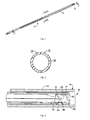
- Figure 1 is a perspective view of one embodiment of a retention member of the left atrial appendage device of the present invention shown in the collapsed position for delivery;
- Figure 2 is a transverse cross-sectional view taken along line 2-2 of Figure 1 ;
- Figure 3 is a cross-sectional view taking along line 3-3 of Figure 1 showing a portion of the retention member within a delivery catheter;
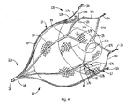
- Figure 4 is a perspective view showing the retention member in the expanded position with floating mesh material positioned therein;
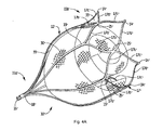
- Figure 4A is a perspective view showing an alternate embodiment of the retention member in the expanded position with floating mesh material positioned therein;
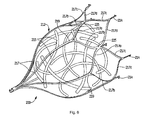
- Figure 5 is a perspective view of an alternate embodiment of the left atrial appendage device of the present invention showing the retention member in the expanded position with floating fibers positioned therein;
- Figure 6 is a perspective view of another alternate embodiment of the left atrial appendage device showing the retention member in the expanded position with floating ribbons positioned therein;
- Figure 7 is an anatomical view showing insertion of the device of Figs. 1-4 through the femoral vein of a patient to access the left atrial appendage;
- Figures 8-8D illustrate the steps of placement of the device of Figures 1-4 in the left atrial appendage wherein:
- Figure 8 illustrates placement of the delivery catheter adjacent the left atrial appendage
- Figure 8A is a close up view illustrating initial deployment of the retention member of the left atrial appendage device
- Figure 8B is a close up view illustrating full deployment of the retention member
- Figure 8C is a close up view illustrating advancement of the delivery device into the retention member.
- Figure 8D illustrates the floating mesh inserted within the retention member
- Figure 9 is a perspective view showing an alternate embodiment of the left atrial appendage device of the present invention showing the retention member in the expanded position with the floating mesh material positioned therein;
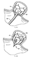
- Figure 9A illustrates placement of the device of Figure 9 in the left atrial appendage.
- the present invention provides a device for blocking blood clot migration from the left atrial appendage ("LAA").
- LAA left atrial appendage
- the device can be inserted minimally invasively.
- the device includes a retention (securement) member and material unattached to the retention member and movably positioned therein to cause blood clots after a period of time.
- the retention member provides for attachment to the appendage wall as well as a retention structure to retain within the appendage the various embodiments of the blood clotting material described below.
- the device 10 includes a securement or retention component (member) 12.
- the retention member 12 forms a containment member to receive therein the material 30 for inducing blood clots.
- the material comprises a mesh 30.
- the retention member 12 has engagement hooks 14 for engaging the appendage wall to retain the retention member 12 within the appendage.
- the mesh 30 is preferably advanced into the member 12 in situ as described below.
- the mesh can be positioned within the retention member 12 in the delivery position and then advanced together with the retention member 12 through the LAA opening.
- mesh 30 floating within the retention member, and preferably free floating therein, is mesh 30, preferably made of a thrombogenic material, which causes blood clots and with the retention member 12 prevents migration of blood clots from the appendage.
- the device 10 is preferably formed from a laser cut tube, although other ways of forming the device are also contemplated.
- the mesh is not shown in Figures 1-3 as in this embodiment the mesh is position proximal of the retention member 12 since it is delivered after the retention member 12 is placed in the body.
- the mesh could alternatively be delivered by a separate catheter after the delivery catheter 50 for the retention member 12 delivers the retention member 12 and is withdrawn.
- the configuration and dimension of the retention member 12 keeps the mesh 30 within the appendage while also providing enough space for movement of the material therein.
- the retention member (component) 12 is in the form of a bell shaped device with struts as described in detail with respect to the filter disclosed in U.S. Patent No. 7,338,512 , the entire contents of which are incorporated herein by reference.
- the device can alternatively have a retention (member component) in the form of the filter disclosed in U.S. Patent No. 7,704,266 , the entire contents of which are incorporated herein by reference.
- the device 10, as shown in Figure 4A has a proximal end 11 a and a distal end 11 b.
- the retention member 12 is preferably composed of shape memory material, such as Nitinol, with an austenitic shape memorized position illustrated in Figure 4 and has a plurality of struts 17 emerging from apex 18 at proximal end 11a and terminating in wall engaging or retention hooks 14 at distal end 11 b.
- shape memory material such as Nitinol
- struts 17 emerging from apex 18 at proximal end 11a and terminating in wall engaging or retention hooks 14 at distal end 11 b.
- six struts are provided although a different number of struts is also contemplated.
- a retrieval hook 16 is positioned on the proximal end 11a to enable the device 10 to be grasped by a snare or other device and removed if desired.
- the struts 17 can be interconnected by interconnecting struts 17a, 17b that curve outwardly away from the central axis then inwardly toward each other to form a V-shaped end portion with hook 14.
- the connecting struts 17a, 17b are joined to connecting struts of adjacent struts at region 25 at a distal portion.
- a closed geometric shape 33 is formed which can be substantially oval, substantially diamond shaped, or other shapes. A fewer or greater number of closed shapes can be formed.
- the struts 17 preferably divide at region 19 into two connecting struts 17a, 17b, angling away from each other, and then join at region 25, extending distally, then angle away from each other at struts 17c, 17d to join an adjacent interconnecting strut (17c or 17d) terminating in hooks 14.
- the thickness of the connecting strut 17a, 17b is about half the thickness of the strut 17 proximal of the bifurcation and about half the thickness of the region 25.
- the interconnecting struts 17 help to provide a retention structure to restrain the floating material positioned inside component 12.
- the configuration and spacing of the struts 17 prevent the mesh (or other material) from migrating out of the appendage, while enabling free floating movement within the appendage.
- the interconnecting struts 17 also stiffen the device to enhance retention and increase the radial force. They also provide a more symmetric and uniform deployment.
- the hooks 14 are configured to engage the appendage wall for maintaining the position of the device 10.
- the struts are preferably flared and create a distal opening and a space between the struts. For clarity, not all the identical parts are labeled throughout the drawings. It should be appreciated that materials other than Nitinol or shape memory are also contemplated.
- the hooks 14 preferably extend substantially perpendicular from the strut and can be formed by torquing the struts so the hooks bend out of the plane.
- a first set of hooks is larger than a second set of hooks, although hooks of the same size are also contemplated.
- the larger hooks when formed in a laser cut tube, are formed so that they occupy a region equivalent to the transverse dimension of two adjacent struts.
- three smaller hooks and three larger hooks are provided in alternating arrangement in the embodiment utilizing six struts.
- the smaller hooks are preferably spaced axially with respect to each other and axially inwardly with respect to the larger hooks as in the filter hooks of U.S. Patent No.
- the penetrating tips 14a penetrate the tissue to retain the device 10, and preferably point toward the proximal end 11a of the device.
- Each of the hooks 14 can have a series of teeth 14c to engage the appendage wall to provide additional retention to prevent movement of the device 10.
- a heel 14d can be provided which extends past the hook 14 to function as a stop to prevent the device from going through the wall.
- the angle of the heel 14d in the smaller hooks is preferably less than the angle in the larger hooks to provide room for nesting of the hooks as shown in Figure 3 . For clarity, not all of the hooks are fully labeled.
- the struts 17' terminate in blunt tips with the radial force of the struts maintaining the position of the device.
- device 10' is identical to device 10 of Figure 4 , and identical parts are labeled with "prime" designations.
- parts identical to those of Figure 4 are not further described as they are identical in structure and function to Figure 4 and thus the description relating to Figure 4 is fully applicable to the device of Figure 4A , except for the blunt tips 14' instead of hooks 14.
- the retention (securement) member 12 is maintained in a substantially straightened softer martensitic configuration within the delivery catheter or sheath 50 for delivery as shown in Figure 3 .
- the smaller hooks preferably nest within the larger hooks.
- Cold saline can be injected during delivery to maintain the struts 17 in this martensitic condition to facilitate exit from the distal opening 52 at the distal end portion 54 of catheter 50.
- the struts 17 exit the delivery sheath (tube) 50 they are warmed by body temperature and move toward their illustrated memorized position as shown in Figure 4 .
- they can be configured so that release from the sheath reduces the stress to enable the retention member 12 to return to its expanded memorized position.
- the device 10 is preferably inserted within delivery catheter 50 through the femoral vein A and advanced through the septum to access the left atrial appendage B. It is positioned in this embodiment with the distal end 11b further from (distal of) the appendage opening and the retrieval hook 16 proximal to the appendage opening, as shown in Figure 8B . When positioned in the appendage, the hooks 14 engage the wall to retain the device 10 in the appendage.
- the device 10 in the embodiment of Figures 1-4 (and 4A) has mesh material unattached to and floating within the retention member 12.
- the mesh material 30 is free-floating within the retention member 12.
- the amount of mesh material 30 is substantial enough to occupy a substantial space within the retention member 12 while still small enough to allow it to freely move within the space defined by the struts 17 of the retention member 12. It is also preferably of sufficient size to be retained by the struts 17.
- the mesh (and other material described herein) could also in some embodiments protrude through some of the struts, while still being retained in the appendage.
- the mesh 30 is preferably in the form a tightly woven material to provide sufficiently small spaces to effectively block blood large clot migration from the appendage while initially allowing blood flow therethrough.
- the material 30 is preferably of sufficient size to occupy a large percentage of the volume of the left atrial appendage.
- the mesh 30 functions to cause blood clotting. That is, once placed, blood flow continues through the device 10 until the mesh causes blood clotting, and eventually the clots can fill the volume, and in some applications the entire volume, of the left atrial appendage, with the large clots preventing migration.
- the mesh 30 can be delivered within the retention member 12 such that in the collapsed position of the retention member 12, the mesh 30 is contained and compressed therein. After delivery, it would expand within the space of the retention member 12, i.e. within the space between the struts 17, since the struts expand when exposed from the delivery catheter.
- the retention member 12 would be placed within the appendage first, and then once in place, the mesh 30 would be delivered through the spaces between the struts 17 for placement within the retention member 12.
- the mesh 30 can be rolled up or folded for delivery. It can be one uniform piece or composed of two or more pieces of mesh.
- the material to induce blood clotting can be in the form of unorganized fibers as shown in Figure 5 .
- the fibers 120 can comprise a large number of threads, formed as separate pieces, and tangled or intertwined together.
- the fibers 120 can be compressed for delivery and then enlarge when released from the delivery catheter.
- the fibers 120 can be delivered inside the retention member 112 or alternatively subsequently placed between the struts of the device 100.
- the retention (securement) member 112 can be delivered with the fibers 120 positioned collapsed (compressed) therein, or alternatively, and preferably, the retention member 112 would be placed in the LAA first, followed by insertion of the fibers 120 in the spaces between the struts 117 of retention member 112 as described herein with respect to mesh 30.
- the fibers 120 are unattached to the retention member 112 and are floating, and preferably free floating, within the space defined by the struts 117 of the retention member 112, causing blood clots in the same manner as described above with respect to the floating mesh of Figure 4 as they effectively block large blood flow clot migration from the appendage while initially allowing blood flow therethrough.
- the material (fibers) is preferably of sufficient size to occupy a large percentage of the volume of the left atrial appendage, and in some embodiments can fill the entire volume. The fibers function to cause blood clotting. That is, once placed, blood flow continues through the device 10 until the material 120 causes blood clotting.
- the retention (securement) member 112 is otherwise identical in structure and function to retention member 12 of Figure 1 , and for convenience, identical parts are labeled in the "100" series, e.g. struts 117 bifurcate at region 119 into interconnecting struts 117a, 117b, join at region 125, then curve outwardly at interconnecting struts 117c, 117d to join another connecting strut and terminate in vessel engaging hooks 114, or alternatively, blunt ends. Consequently, these identical parts of retention member 112 for brevity are not described in further detail as the discussion of retention member 12 is fully applicable to retention member 112.
- the retention member 112 can alternatively be in the form of the filters of the 7,338, 512 and 7,704,226 patents incorporated by reference herein in their entirety.
- the clotting material can be in the form of a plurality of ribbons 215 organized in a set pattern or alternatively randomly intertwined.
- the ribbons 215 are tangled or intertwined together.
- the ribbons 215 can be compressed for delivery and then enlarge with the struts when released from the delivery tube or alternatively placed between the struts 217 of the device 200 after the struts 212 are released and placed within the appendage.
- the retention (securement) member 212 can be delivered with the ribbons 217 positioned collapsed (compressed) therein, or alternatively, and preferably, the retention member 212 would be placed in the LAA first, followed by insertion of the ribbons 215 in the spaces between the struts 217 of retention member 212.
- the ribbons 21 are unattached to the retention member 212 and float within the space defined by the struts 217 of the retention member 212, and, preferably free float, causing blood clots in the same manner as described above with respect to the floating mesh of Figure 4 as they effectively block large blood clot migration from the appendage while initially allowing blood flow therethrough.
- the material is preferably of sufficient size to occupy a large percentage of the volume of the left atrial appendage, and in some instances the entire volume. As with the mesh and fibers described herein, can be fully contained within the retention member 212 or extend beyond the struts. The ribbons function to cause blood clotting.
- the retention member 212 is otherwise identical to retention member 12 of Figure 1 , and for convenience, identical parts are labeled in the "200" series, e.g. struts 217 divide at region 219 into interconnecting struts 217a, 217b, join at region 225, the extend outwardly at 217c, 217d, and terminate in vessel engaging hooks 214, or alternately, blunt ends. Consequently, these identical parts of retention member 212 for brevity are not described in further detail as the discussion of retention member 12 is fully applicable to retention member 212.
- the retention member 212 can alternatively be in the form of the filters of the 7,338,512 and 7, 704,266 patents previously incorporated herein by reference herein in their entirety.
- the mesh (or other clot material such as ribbons or fibers) can be inserted with the retention member in a collapsed (compressed) state within the collapsed retention member or alternatively, if desired, can be delivered in situ within the opening between the struts in an already placed retention member. Such subsequent delivery could reduce the transverse dimension of the device in the collapsed position for delivery.
- the clot material can be inserted with the same catheter as the delivery catheter for the retention member or inserted by another catheter.
- a delivery catheter 50 is inserted through an introducer sheath 100 in the femoral vein A and advanced through the septum to access the left atrial appendage B as shown in Figures 7 and 8 .
- the retention (securement) member 12 is in the collapsed position.
- a pusher 51 is advanced distally from a proximal end of the catheter 50 to advance the device 10 from the catheter 50 as shown in Figures 8A and 8B .
- the catheter 50 is withdrawn (with the pusher abutting retention member 12) to expose the struts.
- the struts 17 of the device 10 return toward their shape memorized deployed position to engage the appendage wall as shown in Figure 8B . The extent they return to their fully memorized position will depend on the size of the appendage.
- the retention member 12 will be positioned at the opening to the left atrial appendage B and be substantially flush with the opening. That is, the proximal retrieval hook would be positioned at the opening.
- a portion of the retention member 12 may extend proximally past the opening into the atrium as shown for example in Figure 8B .
- the device can have struts forming a wider base to conform to the shape of the appendage at the opening with the mesh floating up to the appendage opening. In this use, the portion of reduced transverse dimension remains outside the appendage.
- the mesh or other clot material when expanded floats only in the large transverse dimension region of the retention member and is too large to float within the reduced dimension region, or a portion thereof.
- the mesh or other clot material would thereby not extend outside the appendage, e.g. beyond the appendage opening, if placement of the retention member of Figure 8B is performed.
- the delivery catheter 50 is inserted through a space between the struts 17 and mesh 30 (or other clotting material ) is pushed out of the delivery catheter 50 for placement in the space between the struts 17 of device 10 for free floating movement therein (see Figure 8D ). Delivery catheter 50 is then withdrawn.
- the delivery catheter 50 can be withdrawn and another delivery device containing the clot material can be inserted and advanced to the left atrial appendage and through the struts 17 for delivery of the clotting material.
- the same catheter 50 or a different catheter can be utilized.
- the material described in the embodiments herein preferably free floats within the struts of the retention member, causing the blood to clot which then prevents migration of thrombus from the appendage into the atrium and left ventricle.
- the clot material floating within the retention member is preferably thrombogenic.
- the material inside the retention member could be made of various materials, including, but not limited to, pericardium, SIS, PET, PTFE, etc.
- a wound wire 150 provides a retention (securement) member for mesh 160.
- the wire as shown has a substantially conical configuration so the diameter (transverse dimension) at region 152 exceeds the diameter (transverse dimension) of region 154.
- the floating mesh 160 is inside, preferably free floating.
- the wire could have hooks, barbs or other surfaces to enhance retention in addition to the outward radial force against the appendage.
- the ribbons, fibers, or other clotting materials as described above can be placed inside the wound wire and unattached thereto for floating movement to achieve the blood clot function in the some way as in the embodiments of Figures 1-6 described above.
- the clot material can be delivered with the wire 150, i.e. collapsed within the collapsed wire within the delivery sheath, or alternatively delivered with the same or different catheter after placement of the wire 150 in the appendage.
- Figure 9A illustrates placement of the wire 150 within the left trial appendage B.
- the device can also be used in other conduits such as blood vessels, ureters of fistulas.
Abstract
A device for placement within the left atrial appendage (B) of a patient comprising a retention member (12, 112, 150, 212) and a material (30, 120, 160, 215) positioned within the retention member and unattached thereto. The retention member has a first elongated configuration for delivery and a second expanded configuration for placement within the left atrial appendage. The material is configured to float within the retention member. The retention member can have at least one appendage wall engagement member (14, 14', 114, 214) to secure the retention member to the appendage.
Description
- This application claims priority from provisional application serial no.
61/337,972, filed February 12, 2010 12/151,790, filed May 9, 2008 60/932,448, filed May 31, 2007 11/978,821, filed October 30, 2007 10/889,429, filed July 12, 2004 60/572,274, filed May 18, 2004 10/805,796, filed March 22, 2004 60/538,379, filed January 22, 2004 - This application relates to a device for preventing clot migration from the left atrial appendage of the heart.
- The atrial appendage is a small muscular pouch or cavity attached to the atrium of the heart. The left atrial appendage (LAA) is connected to the wall of the left atrium between the mitral valve and the left pulmonary vein. In proper functioning, the left atrial appendage contracts with the rest of the left atrium during a heart cycle, ensuring regular flow of blood.
- Atrial fibrillation is the irregular and randomized contraction of the atrium working independently of the ventricles. This resulting rapid and chaotic heartbeat produces irregular and turbulent blood flow in the vascular system, resulting in the left atrial appendage not contracting regularly with the left atrium. Consequently, the blood can become stagnant and pool in the appendage, resulting in blood clot formation in the appendage. If the blood clot enters the left ventricle it can enter the cerebral vascular system and cause embolic stroke, resulting in disability and even death.
- One approach to treatment is the administration of medications to break up the blood clots. However, these blood thinning medications are expensive, increase the risk of bleeding and could have adverse side effects. Another approach is to perform invasive surgery to close off the appendage to contain the blood clot within the appendage. Such invasive open heart surgery is time consuming, traumatic to the patient, increases patient risk and recovery time, and increases costs as extended hospital stays are required.
- It is therefore recognized that a minimally invasive approach to closing off the appendage to prevent the migration of blood clots into the ventricle and cranial circulation would be beneficial. These devices, however, need to meet several criteria.
- Such minimally invasive devices need to be collapsible to a small enough dimension to enable delivery through a small incision while being expandable to a sufficiently large dimension with sufficient stability to ensure sealing of the appendage is maintained. These devices also need to be atraumatic. Further, the size of the appendage can vary among patients and therefore the devices need to be expandable to the appropriate size to close off the appendage.
- There have been several attempts in the prior art to provide minimally invasive appendage closure devices. For example, in
U.S. Patent No. 6,488,689 , a capture loop or clip is placed around the appendage to hold the appendage closed. These devices can be traumatic to the vascular structure. The Amplatzer occluder marketed by AGA Medical, provides for stent like expansion within a balloon. However, the diameter of expansion is not controllable and the collapsed configuration is relatively large, disadvantageously increasing the profile for insertion. InU.S. Patent No. 6,152,144 , an occluding member having an outer rim and a thin mesh barrier to provide a seal is placed at the opening of the appendage. Radially extending shape memory members extend from the shaft to anchor the device. An expandable anchoring member is also disclosed. In another embodiment, an occlusive coil having a random configuration is placed in the appendage to induce clot.U.S. Patent Nos. 6,551,303 and6,652,555 disclose a membrane placed across the ostium of the atrial appendage to prevent blood from entering. Various mechanisms such as shape memory prongs, anchors, springs and struts function to retain the membrane. These devices, however, suffer from various deficiencies. - Therefore, there is a need for an improved device for the left atrial appendage which will effectively block blood clot migration from the appendage, remain securely retained within the appendage, and have a reduced delivery profile to minimize the surgical incision and facilitate passage through the vascular system to the appendage.
- The present invention overcomes the problems and deficiencies of the prior art. The present invention provides a device for placement in the left atrial appendage of a patient comprising a retention member and a material positioned within the retention member and unattached thereto. The retention member has a first elongated configuration for delivery and a second expanded configuration for placement within the left atrial appendage. The material is configured to float within the retention member in the expanded configuration of the retention member and cause blot clot within the appendage. The retention member has at least one appendage wall engagement member to secure the retention member to the appendage.
- In some embodiments, in the second configuration, the retention member moves toward a shape memory position.
- In one embodiment, the material comprises a mesh. In another embodiment, the material comprises a plurality of fibers. In another embodiment, the material comprises a plurality of ribbons. Combinations of these materials or use of other materials is also contemplated.
- The present invention also provides in another aspect a device for placement in the left atrial appendage comprising a tube laser cut to form a series of struts, the tube having a first elongated configuration for delivery and a second configuration for placement. In the second configuration, the tube has an expanded configuration and the struts extend outwardly so that a distal region of the struts has a greater dimension than a proximal region and the struts define a space therebetween. A material is positioned within a region defined by the struts and unattached thereto for floating movement in the space between the struts, the material causing blood clots within the appendage.
- In one embodiment, the material comprises a mesh. In another embodiment, the material comprises a plurality of fibers. In another embodiment, the material comprises a plurality of ribbons. Combinations of these materials or use of other materials is also contemplated.
- In another aspect, a method for blocking blot clot migration from a left atrial appendage is also provided comprising the steps of inserting into the left atrial appendage a sheath containing a retention member having a plurality of struts in a reduced profile position, exposing the retention member from the sheath to enable it to expand to engage a wall of the left atrial appendage, subsequently inserting a material in situ within a space between the plurality of struts to enable the material to float within the space, and withdrawing the sheath to leave the retention member in the left atrial appendage so the material floats within the space defined by the plurality of struts to cause blood clots in the appendage.
- Preferably, the retention member has a plurality of shape memory struts and the step of exposing the retention member enables the struts to move toward a shape memorized position.
- Preferred embodiment(s) of the present disclosure are described herein with reference to the drawings wherein:
-
Figure 1 is a perspective view of one embodiment of a retention member of the left atrial appendage device of the present invention shown in the collapsed position for delivery; -
Figure 2 is a transverse cross-sectional view taken along line 2-2 ofFigure 1 ; -
Figure 3 is a cross-sectional view taking along line 3-3 ofFigure 1 showing a portion of the retention member within a delivery catheter; -
Figure 4 is a perspective view showing the retention member in the expanded position with floating mesh material positioned therein; -
Figure 4A is a perspective view showing an alternate embodiment of the retention member in the expanded position with floating mesh material positioned therein; -
Figure 5 is a perspective view of an alternate embodiment of the left atrial appendage device of the present invention showing the retention member in the expanded position with floating fibers positioned therein; -
Figure 6 is a perspective view of another alternate embodiment of the left atrial appendage device showing the retention member in the expanded position with floating ribbons positioned therein; -
Figure 7 is an anatomical view showing insertion of the device ofFigs. 1-4 through the femoral vein of a patient to access the left atrial appendage; -
Figures 8-8D illustrate the steps of placement of the device ofFigures 1-4 in the left atrial appendage wherein: -
Figure 8 illustrates placement of the delivery catheter adjacent the left atrial appendage; -
Figure 8A is a close up view illustrating initial deployment of the retention member of the left atrial appendage device; -
Figure 8B is a close up view illustrating full deployment of the retention member; -
Figure 8C is a close up view illustrating advancement of the delivery device into the retention member; and -
Figure 8D illustrates the floating mesh inserted within the retention member; -
Figure 9 is a perspective view showing an alternate embodiment of the left atrial appendage device of the present invention showing the retention member in the expanded position with the floating mesh material positioned therein; and -
Figure 9A illustrates placement of the device ofFigure 9 in the left atrial appendage. - Referring now in detail to the drawings where like reference numerals identify similar or like components throughout the several views, the present invention provides a device for blocking blood clot migration from the left atrial appendage ("LAA"). The device can be inserted minimally invasively. The device includes a retention (securement) member and material unattached to the retention member and movably positioned therein to cause blood clots after a period of time. The retention member provides for attachment to the appendage wall as well as a retention structure to retain within the appendage the various embodiments of the blood clotting material described below.
- With initial reference to
Figures 1-4 which show the leftatrial appendage device 10 in the low profile delivery (collapsed) configuration for insertion (Figs. 1-3 ) andFig. 4 which shows the device in the expanded configuration for placement, thedevice 10 includes a securement or retention component (member) 12. Theretention member 12 forms a containment member to receive therein thematerial 30 for inducing blood clots. In the embodiment ofFigures 1-4 , the material comprises amesh 30. Theretention member 12 has engagement hooks 14 for engaging the appendage wall to retain theretention member 12 within the appendage. Themesh 30 is preferably advanced into themember 12 in situ as described below. Alternatively, the mesh can be positioned within theretention member 12 in the delivery position and then advanced together with theretention member 12 through the LAA opening. In the embodiment ofFigure 1 , floating within the retention member, and preferably free floating therein, ismesh 30, preferably made of a thrombogenic material, which causes blood clots and with theretention member 12 prevents migration of blood clots from the appendage. Thedevice 10 is preferably formed from a laser cut tube, although other ways of forming the device are also contemplated. - The mesh is not shown in
Figures 1-3 as in this embodiment the mesh is position proximal of theretention member 12 since it is delivered after theretention member 12 is placed in the body. The mesh could alternatively be delivered by a separate catheter after thedelivery catheter 50 for theretention member 12 delivers theretention member 12 and is withdrawn. As can be appreciated, the configuration and dimension of theretention member 12 keeps themesh 30 within the appendage while also providing enough space for movement of the material therein. - Turning to
Figure 4 which illustrates thedevice 10 in the expanded (deployed) position, the retention member (component) 12 is in the form of a bell shaped device with struts as described in detail with respect to the filter disclosed inU.S. Patent No. 7,338,512 , the entire contents of which are incorporated herein by reference. The device can alternatively have a retention (member component) in the form of the filter disclosed inU.S. Patent No. 7,704,266 , the entire contents of which are incorporated herein by reference. Thedevice 10, as shown inFigure 4A has aproximal end 11 a and adistal end 11 b. Theretention member 12 is preferably composed of shape memory material, such as Nitinol, with an austenitic shape memorized position illustrated inFigure 4 and has a plurality ofstruts 17 emerging from apex 18 atproximal end 11a and terminating in wall engaging or retention hooks 14 atdistal end 11 b. In this embodiment, six struts are provided although a different number of struts is also contemplated. Aretrieval hook 16 is positioned on theproximal end 11a to enable thedevice 10 to be grasped by a snare or other device and removed if desired. - The
struts 17 can be interconnected by interconnectingstruts 17a, 17b that curve outwardly away from the central axis then inwardly toward each other to form a V-shaped end portion withhook 14. The connectingstruts 17a, 17b are joined to connecting struts of adjacent struts atregion 25 at a distal portion. Thus, a closedgeometric shape 33 is formed which can be substantially oval, substantially diamond shaped, or other shapes. A fewer or greater number of closed shapes can be formed. That is, thestruts 17 preferably divide atregion 19 into two connectingstruts 17a, 17b, angling away from each other, and then join atregion 25, extending distally, then angle away from each other atstruts hooks 14. Thus, in one embodiment, the thickness of the connectingstrut 17a, 17b is about half the thickness of thestrut 17 proximal of the bifurcation and about half the thickness of theregion 25. The interconnecting struts 17 help to provide a retention structure to restrain the floating material positioned insidecomponent 12. Thus, the configuration and spacing of thestruts 17 prevent the mesh (or other material) from migrating out of the appendage, while enabling free floating movement within the appendage. The interconnecting struts 17 also stiffen the device to enhance retention and increase the radial force. They also provide a more symmetric and uniform deployment. Thehooks 14 are configured to engage the appendage wall for maintaining the position of thedevice 10. The struts are preferably flared and create a distal opening and a space between the struts. For clarity, not all the identical parts are labeled throughout the drawings. It should be appreciated that materials other than Nitinol or shape memory are also contemplated. - The
hooks 14 preferably extend substantially perpendicular from the strut and can be formed by torquing the struts so the hooks bend out of the plane. Preferably, a first set of hooks is larger than a second set of hooks, although hooks of the same size are also contemplated. Preferably, when formed in a laser cut tube, the larger hooks are formed so that they occupy a region equivalent to the transverse dimension of two adjacent struts. Preferably, three smaller hooks and three larger hooks are provided in alternating arrangement in the embodiment utilizing six struts. The smaller hooks are preferably spaced axially with respect to each other and axially inwardly with respect to the larger hooks as in the filter hooks ofU.S. Patent No. 7,704,266 to minimize the collapsed profile (transverse dimension) of the filter when collapsed for insertion. The penetrating tips 14a (Fig. 3 ) penetrate the tissue to retain thedevice 10, and preferably point toward theproximal end 11a of the device. - Each of the
hooks 14 can have a series ofteeth 14c to engage the appendage wall to provide additional retention to prevent movement of thedevice 10. Aheel 14d can be provided which extends past thehook 14 to function as a stop to prevent the device from going through the wall. The angle of theheel 14d in the smaller hooks is preferably less than the angle in the larger hooks to provide room for nesting of the hooks as shown inFigure 3 . For clarity, not all of the hooks are fully labeled. - In an alternate embodiment, the struts 17' terminate in blunt tips with the radial force of the struts maintaining the position of the device. This is shown for example in
Figure 4A , wherein except for blunt tip 14' instead ofhooks 14, device 10' is identical todevice 10 ofFigure 4 , and identical parts are labeled with "prime" designations. For brevity, parts identical to those ofFigure 4 are not further described as they are identical in structure and function toFigure 4 and thus the description relating toFigure 4 is fully applicable to the device ofFigure 4A , except for the blunt tips 14' instead of hooks 14. - The retention (securement)
member 12 is maintained in a substantially straightened softer martensitic configuration within the delivery catheter orsheath 50 for delivery as shown inFigure 3 . The smaller hooks preferably nest within the larger hooks. Cold saline can be injected during delivery to maintain thestruts 17 in this martensitic condition to facilitate exit from thedistal opening 52 at the distal end portion 54 ofcatheter 50. When thestruts 17 exit the delivery sheath (tube) 50, they are warmed by body temperature and move toward their illustrated memorized position as shown inFigure 4 . Alternatively, they can be configured so that release from the sheath reduces the stress to enable theretention member 12 to return to its expanded memorized position. - As shown in
Figure 7 , thedevice 10 is preferably inserted withindelivery catheter 50 through the femoral vein A and advanced through the septum to access the left atrial appendage B. It is positioned in this embodiment with thedistal end 11b further from (distal of) the appendage opening and theretrieval hook 16 proximal to the appendage opening, as shown inFigure 8B . When positioned in the appendage, thehooks 14 engage the wall to retain thedevice 10 in the appendage. - The
device 10 in the embodiment ofFigures 1-4 (and 4A) has mesh material unattached to and floating within theretention member 12. Preferably, themesh material 30 is free-floating within theretention member 12. The amount ofmesh material 30 is substantial enough to occupy a substantial space within theretention member 12 while still small enough to allow it to freely move within the space defined by thestruts 17 of theretention member 12. It is also preferably of sufficient size to be retained by thestruts 17. However, the mesh (and other material described herein) could also in some embodiments protrude through some of the struts, while still being retained in the appendage. Themesh 30 is preferably in the form a tightly woven material to provide sufficiently small spaces to effectively block blood large clot migration from the appendage while initially allowing blood flow therethrough. Thematerial 30 is preferably of sufficient size to occupy a large percentage of the volume of the left atrial appendage. Themesh 30 functions to cause blood clotting. That is, once placed, blood flow continues through thedevice 10 until the mesh causes blood clotting, and eventually the clots can fill the volume, and in some applications the entire volume, of the left atrial appendage, with the large clots preventing migration. - The
mesh 30 can be delivered within theretention member 12 such that in the collapsed position of theretention member 12, themesh 30 is contained and compressed therein. After delivery, it would expand within the space of theretention member 12, i.e. within the space between thestruts 17, since the struts expand when exposed from the delivery catheter. - In an alternate embodiment, the
retention member 12 would be placed within the appendage first, and then once in place, themesh 30 would be delivered through the spaces between thestruts 17 for placement within theretention member 12. - The
mesh 30 can be rolled up or folded for delivery. It can be one uniform piece or composed of two or more pieces of mesh. - In an alternate embodiment, instead of the mesh floating within the space between the struts, the material to induce blood clotting can be in the form of unorganized fibers as shown in
Figure 5 . Thefibers 120 can comprise a large number of threads, formed as separate pieces, and tangled or intertwined together. Thefibers 120 can be compressed for delivery and then enlarge when released from the delivery catheter. Thefibers 120 can be delivered inside theretention member 112 or alternatively subsequently placed between the struts of thedevice 100. That is, as with the mesh of the embodiment ofFigure 4 , the retention (securement)member 112 can be delivered with thefibers 120 positioned collapsed (compressed) therein, or alternatively, and preferably, theretention member 112 would be placed in the LAA first, followed by insertion of thefibers 120 in the spaces between thestruts 117 ofretention member 112 as described herein with respect to mesh 30. - The
fibers 120, like the aforedescribed mesh, are unattached to theretention member 112 and are floating, and preferably free floating, within the space defined by thestruts 117 of theretention member 112, causing blood clots in the same manner as described above with respect to the floating mesh ofFigure 4 as they effectively block large blood flow clot migration from the appendage while initially allowing blood flow therethrough. The material (fibers) is preferably of sufficient size to occupy a large percentage of the volume of the left atrial appendage, and in some embodiments can fill the entire volume. The fibers function to cause blood clotting. That is, once placed, blood flow continues through thedevice 10 until thematerial 120 causes blood clotting. The retention (securement)member 112 is otherwise identical in structure and function toretention member 12 ofFigure 1 , and for convenience, identical parts are labeled in the "100" series, e.g. struts 117 bifurcate atregion 119 into interconnectingstruts 117a, 117b, join atregion 125, then curve outwardly at interconnectingstruts vessel engaging hooks 114, or alternatively, blunt ends. Consequently, these identical parts ofretention member 112 for brevity are not described in further detail as the discussion ofretention member 12 is fully applicable toretention member 112. Theretention member 112 can alternatively be in the form of the filters of the 7,338, 512 and 7,704,226 patents incorporated by reference herein in their entirety. - In an alternate embodiment of
Figure 6 , instead of the mesh floating within the space between thestruts 217, the clotting material can be in the form of a plurality ofribbons 215 organized in a set pattern or alternatively randomly intertwined. Theribbons 215 are tangled or intertwined together. Theribbons 215 can be compressed for delivery and then enlarge with the struts when released from the delivery tube or alternatively placed between thestruts 217 of thedevice 200 after thestruts 212 are released and placed within the appendage. That is, as with the mesh of the embodiment ofFigure 4 , the retention (securement)member 212 can be delivered with theribbons 217 positioned collapsed (compressed) therein, or alternatively, and preferably, theretention member 212 would be placed in the LAA first, followed by insertion of theribbons 215 in the spaces between thestruts 217 ofretention member 212. - The
ribbons 215, like the aforedescribed mesh, are unattached to theretention member 212 and float within the space defined by thestruts 217 of theretention member 212, and, preferably free float, causing blood clots in the same manner as described above with respect to the floating mesh ofFigure 4 as they effectively block large blood clot migration from the appendage while initially allowing blood flow therethrough. The material (ribbons) is preferably of sufficient size to occupy a large percentage of the volume of the left atrial appendage, and in some instances the entire volume. As with the mesh and fibers described herein, can be fully contained within theretention member 212 or extend beyond the struts. The ribbons function to cause blood clotting. That is, once placed, blood flow continues through thedevice 10 until the material causes blood clotting. Theretention member 212 is otherwise identical toretention member 12 ofFigure 1 , and for convenience, identical parts are labeled in the "200" series, e.g. struts 217 divide atregion 219 into interconnectingstruts 217a, 217b, join atregion 225, the extend outwardly at 217c, 217d, and terminate invessel engaging hooks 214, or alternately, blunt ends. Consequently, these identical parts ofretention member 212 for brevity are not described in further detail as the discussion ofretention member 12 is fully applicable toretention member 212. Theretention member 212 can alternatively be in the form of the filters of the 7,338,512 and 7, 704,266 patents previously incorporated herein by reference herein in their entirety. - The mesh (or other clot material such as ribbons or fibers) can be inserted with the retention member in a collapsed (compressed) state within the collapsed retention member or alternatively, if desired, can be delivered in situ within the opening between the struts in an already placed retention member. Such subsequent delivery could reduce the transverse dimension of the device in the collapsed position for delivery. The clot material can be inserted with the same catheter as the delivery catheter for the retention member or inserted by another catheter.
- The method of placement of the device of the present invention will now be described for closing a left atrial appendage in conjunction with the embodiment of
Figure 1 by way of example, with the mesh delivered after placement of the securement member rather than inserted together. It should be understood that the other embodiments disclosed herein would be inserted in a similar fashion. Adelivery catheter 50 is inserted through anintroducer sheath 100 in the femoral vein A and advanced through the septum to access the left atrial appendage B as shown inFigures 7 and8 . For insertion, the retention (securement)member 12 is in the collapsed position. - A
pusher 51 is advanced distally from a proximal end of thecatheter 50 to advance thedevice 10 from thecatheter 50 as shown inFigures 8A and 8B . Alternatively, thecatheter 50 is withdrawn (with the pusher abutting retention member 12) to expose the struts. As thestruts 17 of thedevice 10 are exposed, they return toward their shape memorized deployed position to engage the appendage wall as shown inFigure 8B . The extent they return to their fully memorized position will depend on the size of the appendage. - In some embodiments, the
retention member 12 will be positioned at the opening to the left atrial appendage B and be substantially flush with the opening. That is, the proximal retrieval hook would be positioned at the opening. Alternatively, a portion of theretention member 12 may extend proximally past the opening into the atrium as shown for example inFigure 8B . For example, as shown inFigure 8B , the device can have struts forming a wider base to conform to the shape of the appendage at the opening with the mesh floating up to the appendage opening. In this use, the portion of reduced transverse dimension remains outside the appendage. It is contemplated in some embodiments that the mesh or other clot material when expanded floats only in the large transverse dimension region of the retention member and is too large to float within the reduced dimension region, or a portion thereof. In such embodiments, the mesh or other clot material would thereby not extend outside the appendage, e.g. beyond the appendage opening, if placement of the retention member ofFigure 8B is performed. - After placement within the appendage as shown in
Figure 8B , thedelivery catheter 50 is inserted through a space between thestruts 17 and mesh 30 (or other clotting material ) is pushed out of thedelivery catheter 50 for placement in the space between thestruts 17 ofdevice 10 for free floating movement therein (seeFigure 8D ).Delivery catheter 50 is then withdrawn. As can be appreciated, as an alternative to the clotting material retained indelivery catheter 50 proximal of theretention member 12 for delivery, afterretention member 12 placement, thedelivery catheter 50 can be withdrawn and another delivery device containing the clot material can be inserted and advanced to the left atrial appendage and through thestruts 17 for delivery of the clotting material. Thus, for in situ delivery, thesame catheter 50 or a different catheter can be utilized. - As can be appreciated, the material described in the embodiments herein preferably free floats within the struts of the retention member, causing the blood to clot which then prevents migration of thrombus from the appendage into the atrium and left ventricle. The clot material floating within the retention member is preferably thrombogenic.
- Note the material inside the retention member could be made of various materials, including, but not limited to, pericardium, SIS, PET, PTFE, etc.
- In the alternate embodiment of
Figure 9 , awound wire 150 provides a retention (securement) member for mesh 160. The wire as shown has a substantially conical configuration so the diameter (transverse dimension) atregion 152 exceeds the diameter (transverse dimension) ofregion 154. The floating mesh 160 is inside, preferably free floating. The wire could have hooks, barbs or other surfaces to enhance retention in addition to the outward radial force against the appendage. The ribbons, fibers, or other clotting materials as described above can be placed inside the wound wire and unattached thereto for floating movement to achieve the blood clot function in the some way as in the embodiments ofFigures 1-6 described above. The clot material can be delivered with thewire 150, i.e. collapsed within the collapsed wire within the delivery sheath, or alternatively delivered with the same or different catheter after placement of thewire 150 in the appendage.Figure 9A illustrates placement of thewire 150 within the left trial appendage B. - As can be appreciated, although described for use in the left atrial appendage of the heart, the device can also be used in other conduits such as blood vessels, ureters of fistulas.
- While the above description contains many specifics, those specifics should not be construed as limitations on the scope of the disclosure, but merely as exemplifications of preferred embodiments thereof. For example, other materials can be contained or within the retention member to function to cause blood clot to block clot migration from the left atrial appendage. Those skilled in the art will envision many other possible variations that are within the scope and spirit of the disclosure as defined by the claims appended hereto.
Claims (15)
- A device for placement in the left atrial appendage (B) of a patient comprising a retention member (12, 112, 150, 212) having a first elongated configuration for delivery and a second expanded configuration for placement within the left atrial appendage, a material (30, 120, 160, 215) positioned within the retention member and unattached thereto for floating movement therein, in the expanded configuration of the retention member, the retention member having a larger transverse dimension, the retention member having at least one appendage wall engagement member (14, 14', 114, 214) to secure the retention member to the appendage.
- The device of claim 1, wherein the retention member (12, 112, 150, 212) is composed of a shape memory material, and in the expanded configuration the retention member moves toward a shape memory position.
- The device of claim 1 or 2, wherein the material comprises a mesh (30, 160).
- The device of claim 1, 2 or 3, wherein the material comprises a plurality of intertwined fibers (120).
- The device of any preceding claim, wherein the material comprises a plurality of intertwined ribbons (215).
- The device of any preceding claim, wherein the retention member (12, 112, 212) has a plurality of struts (17, 117, 217) defining a space therebetween and the material (30, 120, 215) floats freely within the space.
- The device of any preceding claim, wherein the engagement member (14, 114, 214) includes a plurality of teeth.
- The device of any preceding claim, wherein the retention member (12, 112, 212) has a plurality of struts (17, 117, 217) and the struts terminate in the engagement members (14, 14', 114, 214).
- The device of any preceding claim, wherein the retention member (150) comprises a wound wire.
- A device for placement in the left atrial appendage (B), for example dependent on any preceding claim, wherein the device comprises a tube laser cut to form a series of struts (17, 117, 217), the tube having a first elongated configuration for delivery and a second expanded configuration for placement, the struts extending outwardly so that a distal region of the struts has a greater dimension than a proximal region, the struts defining a space therebetween, a material (30, 120, 160, 215) non attachably positioned within the space defined by the struts and floating therein for causing blood clots within the appendage.
- The device of claim 10, wherein the material comprises a mesh (30, 160).
- The device of claim 10 or 11, wherein the material comprises a plurality of intertwined fibers (120).
- The device of claim 10, 11 or 12, wherein the material comprises a plurality of intertwined ribbons (215).
- The device of any one of claims 10 to 13, wherein the struts (17, 117, 217) are composed of shape memory material.
- The device of any one of claims 10 to 14, wherein the material (30, 120, 215) is positionable within the space defined by the struts (17, 117, 217) subsequent to placement of the struts in the appendage.
Applications Claiming Priority (2)
| Application Number | Priority Date | Filing Date | Title |
|---|---|---|---|
| US33797210P | 2010-02-12 | 2010-02-12 | |
| US13/008,990 US20110208233A1 (en) | 2004-01-22 | 2011-01-19 | Device for preventing clot migration from left atrial appendage |
Publications (1)
| Publication Number | Publication Date |
|---|---|
| EP2363075A1 true EP2363075A1 (en) | 2011-09-07 |
Family
ID=44146603
Family Applications (1)
| Application Number | Title | Priority Date | Filing Date |
|---|---|---|---|
| EP11153192A Withdrawn EP2363075A1 (en) | 2010-02-12 | 2011-02-03 | Device for preventing clot migration from left atrial appendage |
Country Status (5)
| Country | Link |
|---|---|
| US (2) | US20110208233A1 (en) |
| EP (1) | EP2363075A1 (en) |
| JP (1) | JP2011161233A (en) |
| AU (1) | AU2011200581A1 (en) |
| CA (1) | CA2729530A1 (en) |
Cited By (20)
| Publication number | Priority date | Publication date | Assignee | Title |
|---|---|---|---|---|
| WO2013049448A1 (en) * | 2011-09-29 | 2013-04-04 | Covidien Lp | Vascular remodeling device |
| US8747597B2 (en) | 2008-04-21 | 2014-06-10 | Covidien Lp | Methods for making braid-ball occlusion devices |
| US8926681B2 (en) | 2010-01-28 | 2015-01-06 | Covidien Lp | Vascular remodeling device |
| US9089332B2 (en) | 2011-03-25 | 2015-07-28 | Covidien Lp | Vascular remodeling device |
| US9095342B2 (en) | 2009-11-09 | 2015-08-04 | Covidien Lp | Braid ball embolic device features |
| US9179918B2 (en) | 2008-07-22 | 2015-11-10 | Covidien Lp | Vascular remodeling device |
| US9295571B2 (en) | 2013-01-17 | 2016-03-29 | Covidien Lp | Methods and apparatus for luminal stenting |
| US9314248B2 (en) | 2012-11-06 | 2016-04-19 | Covidien Lp | Multi-pivot thrombectomy device |
| US9393022B2 (en) | 2011-02-11 | 2016-07-19 | Covidien Lp | Two-stage deployment aneurysm embolization devices |
| EP2931354A4 (en) * | 2012-12-14 | 2016-08-03 | Corquest Medical Inc | Assembly and method for left atrial appendage occlusion |
| US9463105B2 (en) | 2013-03-14 | 2016-10-11 | Covidien Lp | Methods and apparatus for luminal stenting |
| US9468442B2 (en) | 2010-01-28 | 2016-10-18 | Covidien Lp | Vascular remodeling device |
| WO2017200866A1 (en) * | 2016-05-17 | 2017-11-23 | The Cleveland Clinic Foundation | Apparatus for blocking bloodflow through a dissected aorta |
| WO2018214826A1 (en) * | 2017-05-23 | 2018-11-29 | 杭州诺茂医疗科技有限公司 | Left atrial appendage occluder having improved sealing performance and manufacturing method thereof |
| US10314594B2 (en) | 2012-12-14 | 2019-06-11 | Corquest Medical, Inc. | Assembly and method for left atrial appendage occlusion |
| US10478194B2 (en) | 2015-09-23 | 2019-11-19 | Covidien Lp | Occlusive devices |
| US10736758B2 (en) | 2013-03-15 | 2020-08-11 | Covidien | Occlusive device |
| US10813630B2 (en) | 2011-08-09 | 2020-10-27 | Corquest Medical, Inc. | Closure system for atrial wall |
| WO2022095268A1 (en) * | 2020-11-06 | 2022-05-12 | 上海普实医疗器械股份有限公司 | Occlusion device for left atrial appendage, and use method thereof |
| US11707371B2 (en) | 2008-05-13 | 2023-07-25 | Covidien Lp | Braid implant delivery systems |
Families Citing this family (71)
| Publication number | Priority date | Publication date | Assignee | Title |
|---|---|---|---|---|
| JP5148598B2 (en) | 2006-05-03 | 2013-02-20 | ラプトール リッジ, エルエルシー | Tissue closure system and method |
| EP2157937B1 (en) | 2007-06-04 | 2017-03-22 | Sequent Medical, Inc. | Devices for treatment of vascular defects |
| WO2009032834A1 (en) | 2007-09-07 | 2009-03-12 | Crusader Medical Llc | Percutaneous permanent retrievable vascular filter |
| US8795318B2 (en) | 2007-09-07 | 2014-08-05 | Merit Medical Systems, Inc. | Percutaneous retrievable vascular filter |
| WO2009052432A2 (en) | 2007-10-19 | 2009-04-23 | Coherex Medical, Inc. | Medical device for modification of left atrial appendange and related systems and methods |
| CN106974691A (en) | 2008-05-02 | 2017-07-25 | 斯昆特医疗公司 | Thread device for treating vascular defects |
| US9402707B2 (en) | 2008-07-22 | 2016-08-02 | Neuravi Limited | Clot capture systems and associated methods |
| WO2010081033A1 (en) | 2009-01-08 | 2010-07-15 | Coherex Medical, Inc. | Medical device for modification of left atrial appendage and related systems and methods |
| US9649115B2 (en) | 2009-06-17 | 2017-05-16 | Coherex Medical, Inc. | Medical device for modification of left atrial appendage and related systems and methods |
| US10631969B2 (en) | 2009-06-17 | 2020-04-28 | Coherex Medical, Inc. | Medical device for modification of left atrial appendage and related systems and methods |
| US9351716B2 (en) | 2009-06-17 | 2016-05-31 | Coherex Medical, Inc. | Medical device and delivery system for modification of left atrial appendage and methods thereof |
| CA2958338C (en) * | 2009-06-17 | 2019-04-16 | Coherex Medical, Inc. | Medical device for modification of left atrial appendage and related systems and methods |
| US10064628B2 (en) | 2009-06-17 | 2018-09-04 | Coherex Medical, Inc. | Medical device for modification of left atrial appendage and related systems and methods |
| US20110152993A1 (en) | 2009-11-05 | 2011-06-23 | Sequent Medical Inc. | Multiple layer filamentary devices or treatment of vascular defects |
| EP2629684B1 (en) | 2010-10-22 | 2018-07-25 | Neuravi Limited | Clot engagement and removal system |
| US11259824B2 (en) | 2011-03-09 | 2022-03-01 | Neuravi Limited | Clot retrieval device for removing occlusive clot from a blood vessel |
| WO2014139845A1 (en) | 2013-03-14 | 2014-09-18 | Neuravi Limited | A clot retrieval device for removing occlusive clot from a blood vessel |
| WO2012120490A2 (en) | 2011-03-09 | 2012-09-13 | Neuravi Limited | A clot retrieval device for removing occlusive clot from a blood vessel |
| US8764793B2 (en) * | 2011-06-17 | 2014-07-01 | Northwestern University | Left atrial appendage occluder |
| US8734480B2 (en) | 2011-08-05 | 2014-05-27 | Merit Medical Systems, Inc. | Vascular filter |
| US8740931B2 (en) | 2011-08-05 | 2014-06-03 | Merit Medical Systems, Inc. | Vascular filter |
| EP4324409A3 (en) | 2011-11-01 | 2024-03-13 | Coherex Medical, Inc. | Medical device for modification of left atrial appendage and related systems and methods |
| WO2013126773A1 (en) | 2012-02-23 | 2013-08-29 | Merit Medical Systems, Inc. | Vascular filter |
| US10617425B2 (en) | 2014-03-10 | 2020-04-14 | Conformal Medical, Inc. | Devices and methods for excluding the left atrial appendage |
| US11399842B2 (en) | 2013-03-13 | 2022-08-02 | Conformal Medical, Inc. | Devices and methods for excluding the left atrial appendage |
| JP6423851B2 (en) | 2013-03-13 | 2018-11-14 | アーロン・ヴィ・カプラン | Device for emptying the left atrial appendage |
| ES2713633T3 (en) | 2013-03-14 | 2019-05-23 | Neuravi Ltd | Devices and methods for elimination of severe blockages of blood vessels |
| US9433429B2 (en) | 2013-03-14 | 2016-09-06 | Neuravi Limited | Clot retrieval devices |
| US9089414B2 (en) * | 2013-03-22 | 2015-07-28 | Edwards Lifesciences Corporation | Device and method for increasing flow through the left atrial appendage |
| EP3030194B1 (en) | 2013-08-09 | 2019-03-13 | Merit Medical Systems, Inc. | Vascular filter delivery systems |
| US9955976B2 (en) | 2013-08-16 | 2018-05-01 | Sequent Medical, Inc. | Filamentary devices for treatment of vascular defects |
| US9078658B2 (en) | 2013-08-16 | 2015-07-14 | Sequent Medical, Inc. | Filamentary devices for treatment of vascular defects |
| WO2015077356A1 (en) | 2013-11-19 | 2015-05-28 | Wheeler William K | Fastener applicator with interlock |
| JP6302131B2 (en) | 2014-03-31 | 2018-03-28 | ジトメッド・エスピー・ゼット・オー・オーJitmed Sp Z O.O. | Left atrial appendage obturator |
| US9629635B2 (en) | 2014-04-14 | 2017-04-25 | Sequent Medical, Inc. | Devices for therapeutic vascular procedures |
| CN104287804B (en) * | 2014-10-27 | 2017-02-22 | 梁巧英 | Biological cavity blocking device |
| US10363054B2 (en) | 2014-11-26 | 2019-07-30 | Neuravi Limited | Clot retrieval device for removing occlusive clot from a blood vessel |
| US10617435B2 (en) | 2014-11-26 | 2020-04-14 | Neuravi Limited | Clot retrieval device for removing clot from a blood vessel |
| US11253278B2 (en) | 2014-11-26 | 2022-02-22 | Neuravi Limited | Clot retrieval system for removing occlusive clot from a blood vessel |
| CN105796148B (en) | 2014-12-31 | 2018-06-05 | 先健科技(深圳)有限公司 | Occluder for left auricle |
| CN105662516A (en) | 2016-03-03 | 2016-06-15 | 上海普实医疗器械科技有限公司 | Left aurcle plugging device |
| US11039822B2 (en) * | 2016-03-18 | 2021-06-22 | Shanghai Microport Medical (Group) Co., Ltd. | Left atrial appendage closure and delivery system thereof |
| JP7046924B2 (en) | 2016-09-06 | 2022-04-04 | ニューラヴィ・リミテッド | Clot recovery device for removing obstructive clots from blood vessels |
| CN106333725A (en) * | 2016-09-27 | 2017-01-18 | 张雯 | Left aurcle plugging device and left aurcle plugging apparatus |
| WO2018081466A2 (en) | 2016-10-27 | 2018-05-03 | Conformal Medical, Inc. | Devices and methods for excluding the left atrial appendage |
| US11426172B2 (en) | 2016-10-27 | 2022-08-30 | Conformal Medical, Inc. | Devices and methods for excluding the left atrial appendage |
| US11812968B2 (en) * | 2017-05-10 | 2023-11-14 | Lifetech Scientific (Shenzhen) Co. Ltd. | Left atrial appendage occluder |
| US11191547B2 (en) | 2018-01-26 | 2021-12-07 | Syntheon 2.0, LLC | Left atrial appendage clipping device and methods for clipping the LAA |
| AU2019243731A1 (en) | 2018-03-28 | 2020-10-08 | Datascope Corp. | Device for atrial appendage exclusion |
| US10842498B2 (en) | 2018-09-13 | 2020-11-24 | Neuravi Limited | Systems and methods of restoring perfusion to a vessel |
| CN110960279B (en) * | 2018-09-29 | 2023-06-16 | 上海佐心医疗科技有限公司 | Left auricle plugging device and left auricle plugging system |
| US11406416B2 (en) | 2018-10-02 | 2022-08-09 | Neuravi Limited | Joint assembly for vasculature obstruction capture device |
| WO2020163507A1 (en) | 2019-02-08 | 2020-08-13 | Conformal Medical, Inc. | Devices and methods for excluding the left atrial appendage |
| CN113573765A (en) | 2019-03-15 | 2021-10-29 | 后续医疗股份有限公司 | Silk device for treating vascular defects |
| EP3908208A4 (en) | 2019-03-15 | 2022-10-19 | Sequent Medical, Inc. | Filamentary devices having a flexible joint for treatment of vascular defects |
| CN113556985A (en) | 2019-03-15 | 2021-10-26 | 后续医疗股份有限公司 | Silk device for treating vascular defects |
| WO2020207485A1 (en) * | 2019-04-11 | 2020-10-15 | 杭州唯强医疗科技有限公司 | Occluder and locking system of occluder |
| US10925615B2 (en) | 2019-05-03 | 2021-02-23 | Syntheon 2.0, LLC | Recapturable left atrial appendage clipping device and methods for recapturing a left atrial appendage clip |
| US11369355B2 (en) | 2019-06-17 | 2022-06-28 | Coherex Medical, Inc. | Medical device and system for occluding a tissue opening and method thereof |
| US11712231B2 (en) | 2019-10-29 | 2023-08-01 | Neuravi Limited | Proximal locking assembly design for dual stent mechanical thrombectomy device |
| US11517340B2 (en) | 2019-12-03 | 2022-12-06 | Neuravi Limited | Stentriever devices for removing an occlusive clot from a vessel and methods thereof |
| US11871946B2 (en) | 2020-04-17 | 2024-01-16 | Neuravi Limited | Clot retrieval device for removing clot from a blood vessel |
| US11730501B2 (en) | 2020-04-17 | 2023-08-22 | Neuravi Limited | Floating clot retrieval device for removing clots from a blood vessel |
| US11717308B2 (en) | 2020-04-17 | 2023-08-08 | Neuravi Limited | Clot retrieval device for removing heterogeneous clots from a blood vessel |
| US11737771B2 (en) | 2020-06-18 | 2023-08-29 | Neuravi Limited | Dual channel thrombectomy device |
| US11937836B2 (en) | 2020-06-22 | 2024-03-26 | Neuravi Limited | Clot retrieval system with expandable clot engaging framework |
| US11395669B2 (en) | 2020-06-23 | 2022-07-26 | Neuravi Limited | Clot retrieval device with flexible collapsible frame |
| US11439418B2 (en) | 2020-06-23 | 2022-09-13 | Neuravi Limited | Clot retrieval device for removing clot from a blood vessel |
| US11864781B2 (en) | 2020-09-23 | 2024-01-09 | Neuravi Limited | Rotating frame thrombectomy device |
| US11812969B2 (en) | 2020-12-03 | 2023-11-14 | Coherex Medical, Inc. | Medical device and system for occluding a tissue opening and method thereof |
| US11937837B2 (en) | 2020-12-29 | 2024-03-26 | Neuravi Limited | Fibrin rich / soft clot mechanical thrombectomy device |
Citations (10)
| Publication number | Priority date | Publication date | Assignee | Title |
|---|---|---|---|---|
| US5683411A (en) * | 1994-04-06 | 1997-11-04 | William Cook Europe A/S | Medical article for implantation into the vascular system of a patient |
| WO1999030640A1 (en) * | 1997-12-15 | 1999-06-24 | Boston Scientific Limited | Sheet metal aneurysm neck bridge |
| US6152144A (en) | 1998-11-06 | 2000-11-28 | Appriva Medical, Inc. | Method and device for left atrial appendage occlusion |
| US6488689B1 (en) | 1999-05-20 | 2002-12-03 | Aaron V. Kaplan | Methods and apparatus for transpericardial left atrial appendage closure |
| US6551303B1 (en) | 1999-10-27 | 2003-04-22 | Atritech, Inc. | Barrier device for ostium of left atrial appendage |
| US6652555B1 (en) | 1999-10-27 | 2003-11-25 | Atritech, Inc. | Barrier device for covering the ostium of left atrial appendage |
| US7338512B2 (en) | 2004-01-22 | 2008-03-04 | Rex Medical, L.P. | Vein filter |
| WO2008150346A1 (en) * | 2007-05-31 | 2008-12-11 | Rex Medical, L.P. | Closure device for left atrial appendage |
| US7704266B2 (en) | 2004-01-22 | 2010-04-27 | Rex Medical, L.P. | Vein filter |
| WO2010056535A1 (en) * | 2008-10-29 | 2010-05-20 | Cook Biotech Incorporated | Vascular plugs |
Family Cites Families (80)
| Publication number | Priority date | Publication date | Assignee | Title |
|---|---|---|---|---|
| US3744492A (en) * | 1971-04-07 | 1973-07-10 | S Leibinsohn | Drip chamber |
| ZA793232B (en) * | 1978-07-03 | 1980-09-24 | Smiths Industries Ltd | Connectors |
| US4643184A (en) * | 1982-09-29 | 1987-02-17 | Mobin Uddin Kazi | Embolus trap |
| US4832055A (en) * | 1988-07-08 | 1989-05-23 | Palestrant Aubrey M | Mechanically locking blood clot filter |
| US5059205A (en) * | 1989-09-07 | 1991-10-22 | Boston Scientific Corporation | Percutaneous anti-migration vena cava filter |
| US6059825A (en) * | 1992-03-05 | 2000-05-09 | Angiodynamics, Inc. | Clot filter |
| US5334210A (en) * | 1993-04-09 | 1994-08-02 | Cook Incorporated | Vascular occlusion assembly |
| EP0746236B1 (en) * | 1993-10-01 | 2003-08-20 | Boston Scientific Corporation | Improved vena cava filter |
| FR2714814B1 (en) * | 1994-01-10 | 1996-03-29 | Bentex Trading Sa | Device intended to be placed in a vessel with flattened fixing lugs. |
| US5846261A (en) * | 1994-07-08 | 1998-12-08 | Aga Medical Corp. | Percutaneous catheter directed occlusion devices |
| US5725552A (en) * | 1994-07-08 | 1998-03-10 | Aga Medical Corporation | Percutaneous catheter directed intravascular occlusion devices |
| EP0769926B2 (en) * | 1994-07-08 | 2006-11-22 | ev3 Inc. | Intravascular filtering device |
| US5709704A (en) * | 1994-11-30 | 1998-01-20 | Boston Scientific Corporation | Blood clot filtering |
| US5885258A (en) * | 1996-02-23 | 1999-03-23 | Memory Medical Systems, Inc. | Medical instrument with slotted memory metal tube |
| US5782748A (en) * | 1996-07-10 | 1998-07-21 | Symbiosis Corporation | Endoscopic surgical instruments having detachable proximal and distal portions |
| US7073504B2 (en) * | 1996-12-18 | 2006-07-11 | Ams Research Corporation | Contraceptive system and method of use |
| US5800457A (en) * | 1997-03-05 | 1998-09-01 | Gelbfish; Gary A. | Intravascular filter and associated methodology |
| CA2298637A1 (en) * | 1997-08-04 | 1999-02-11 | Jennifer J. Mccrory | Occlusion system for aneurysm repair |
| US7713282B2 (en) * | 1998-11-06 | 2010-05-11 | Atritech, Inc. | Detachable atrial appendage occlusion balloon |
| US7044134B2 (en) * | 1999-11-08 | 2006-05-16 | Ev3 Sunnyvale, Inc | Method of implanting a device in the left atrial appendage |
| US7128073B1 (en) * | 1998-11-06 | 2006-10-31 | Ev3 Endovascular, Inc. | Method and device for left atrial appendage occlusion |
| US6355051B1 (en) * | 1999-03-04 | 2002-03-12 | Bioguide Consulting, Inc. | Guidewire filter device |
| US6368338B1 (en) * | 1999-03-05 | 2002-04-09 | Board Of Regents, The University Of Texas | Occlusion method and apparatus |
| US6436120B1 (en) * | 1999-04-20 | 2002-08-20 | Allen J. Meglin | Vena cava filter |
| US6267776B1 (en) * | 1999-05-03 | 2001-07-31 | O'connell Paul T. | Vena cava filter and method for treating pulmonary embolism |
| US6375668B1 (en) * | 1999-06-02 | 2002-04-23 | Hanson S. Gifford | Devices and methods for treating vascular malformations |
| US6235044B1 (en) * | 1999-08-04 | 2001-05-22 | Scimed Life Systems, Inc. | Percutaneous catheter and guidewire for filtering during ablation of mycardial or vascular tissue |
| US6231561B1 (en) * | 1999-09-20 | 2001-05-15 | Appriva Medical, Inc. | Method and apparatus for closing a body lumen |
| US6689150B1 (en) * | 1999-10-27 | 2004-02-10 | Atritech, Inc. | Filter apparatus for ostium of left atrial appendage |
| US6425909B1 (en) * | 1999-11-04 | 2002-07-30 | Concentric Medical, Inc. | Methods and devices for filtering fluid flow through a body structure |
| US6994092B2 (en) * | 1999-11-08 | 2006-02-07 | Ev3 Sunnyvale, Inc. | Device for containing embolic material in the LAA having a plurality of tissue retention structures |
| US6660021B1 (en) * | 1999-12-23 | 2003-12-09 | Advanced Cardiovascular Systems, Inc. | Intravascular device and system |
| US6293906B1 (en) * | 2000-01-14 | 2001-09-25 | Acorn Cardiovascular, Inc. | Delivery of cardiac constraint jacket |
| US6346117B1 (en) * | 2000-03-02 | 2002-02-12 | Prodesco, Inc. | Bag for use in the intravascular treatment of saccular aneurysms |
| US6468290B1 (en) * | 2000-06-05 | 2002-10-22 | Scimed Life Systems, Inc. | Two-planar vena cava filter with self-centering capabilities |
| AU2001291201A1 (en) * | 2000-09-21 | 2002-04-02 | Atritech, Inc. | Apparatus for implanting devices in atrial appendages |
| US6589265B1 (en) * | 2000-10-31 | 2003-07-08 | Endovascular Technologies, Inc. | Intrasaccular embolic device |
| US6689151B2 (en) * | 2001-01-25 | 2004-02-10 | Scimed Life Systems, Inc. | Variable wall thickness for delivery sheath housing |
| US6506205B2 (en) * | 2001-02-20 | 2003-01-14 | Mark Goldberg | Blood clot filtering system |
| US7011094B2 (en) * | 2001-03-02 | 2006-03-14 | Emphasys Medical, Inc. | Bronchial flow control devices and methods of use |
| JP2005508208A (en) * | 2001-06-04 | 2005-03-31 | アルバート・アインシュタイン・ヘルスケア・ネットワーク | Cardiac stimulator with thrombus filter and atrial pacemaker |
| US7674245B2 (en) * | 2001-06-07 | 2010-03-09 | Cardiac Pacemakers, Inc. | Method and apparatus for an adjustable shape guide catheter |
| WO2002102436A2 (en) * | 2001-06-14 | 2002-12-27 | Cook Incorporated | Endovascular filter |
| US6599307B1 (en) * | 2001-06-29 | 2003-07-29 | Advanced Cardiovascular Systems, Inc. | Filter device for embolic protection systems |
| EP1277448B1 (en) * | 2001-07-13 | 2006-06-07 | B. Braun Medical SAS | System of vascular protection and angioplasty device |
| US7097651B2 (en) * | 2001-09-06 | 2006-08-29 | Advanced Cardiovascular Systems, Inc. | Embolic protection basket |
| US6811560B2 (en) * | 2001-09-20 | 2004-11-02 | Cordis Neurovascular, Inc. | Stent aneurysm embolization method and device |
| US20030065345A1 (en) * | 2001-09-28 | 2003-04-03 | Kevin Weadock | Anastomosis devices and methods for treating anastomotic sites |
| JP4429589B2 (en) * | 2001-11-15 | 2010-03-10 | コーディス・ニューロバスキュラー・インコーポレイテッド | Aneurysm embolization device using an occluding member |
| US6890340B2 (en) * | 2001-11-29 | 2005-05-10 | Medtronic Vascular, Inc. | Apparatus for temporary intraluminal protection |
| US6958074B2 (en) * | 2002-01-07 | 2005-10-25 | Cordis Corporation | Releasable and retrievable vascular filter system |
| EP1469790B1 (en) * | 2002-01-25 | 2016-10-19 | Atritech, Inc. | Atrial appendage blood filtration systems |
| JP4440787B2 (en) * | 2002-09-19 | 2010-03-24 | メモリー・メタル・ホーランド・ベスローテン・フェンノートシャップ | Vascular filter with improved strength and flexibility |
| US6857428B2 (en) * | 2002-10-24 | 2005-02-22 | W. Keith Thornton | Custom fitted mask and method of forming same |
| US6989021B2 (en) * | 2002-10-31 | 2006-01-24 | Cordis Corporation | Retrievable medical filter |
| WO2004049973A1 (en) * | 2002-11-29 | 2004-06-17 | Vascular Interventional Technologies Inc. | Embolus blood clot filter |
| US7316708B2 (en) * | 2002-12-05 | 2008-01-08 | Cardiac Dimensions, Inc. | Medical device delivery system |
| US20040111111A1 (en) * | 2002-12-10 | 2004-06-10 | Scimed Life Systems, Inc. | Intravascular filter membrane with shape memory |
| US20050165469A1 (en) * | 2002-12-24 | 2005-07-28 | Michael Hogendijk | Vascular prosthesis including torsional stabilizer and methods of use |
| US7220271B2 (en) * | 2003-01-30 | 2007-05-22 | Ev3 Inc. | Embolic filters having multiple layers and controlled pore size |
| WO2004069290A2 (en) * | 2003-01-31 | 2004-08-19 | Cordis Corporation | Filter retrieval catheter system, and methods |
| US7896898B2 (en) * | 2003-07-30 | 2011-03-01 | Boston Scientific Scimed, Inc. | Self-centering blood clot filter |
| US6972025B2 (en) * | 2003-11-18 | 2005-12-06 | Scimed Life Systems, Inc. | Intravascular filter with bioabsorbable centering element |
| US7566336B2 (en) * | 2003-11-25 | 2009-07-28 | Cardia, Inc. | Left atrial appendage closure device |
| US7976562B2 (en) * | 2004-01-22 | 2011-07-12 | Rex Medical, L.P. | Method of removing a vein filter |
| WO2005072652A1 (en) * | 2004-01-27 | 2005-08-11 | Med Institute, Inc. | Anchoring barb for attachment to a medical prosthesis |
| US8998944B2 (en) * | 2004-06-10 | 2015-04-07 | Lifescreen Sciences Llc | Invertible intravascular filter |
| CA2580124C (en) * | 2004-09-27 | 2014-05-13 | Rex Medical, L.P. | Vein filter |
| US7279000B2 (en) * | 2004-09-29 | 2007-10-09 | Angiodynamics Inc | Permanent blood clot filter with capability of being retrieved |
| US7959645B2 (en) * | 2004-11-03 | 2011-06-14 | Boston Scientific Scimed, Inc. | Retrievable vena cava filter |
| US20060106420A1 (en) * | 2004-11-12 | 2006-05-18 | Medtronic Vascular, Inc. | Patch for treating a septal defect |
| US8029529B1 (en) * | 2005-01-19 | 2011-10-04 | C. R. Bard, Inc. | Retrievable filter |
| US7850708B2 (en) * | 2005-06-20 | 2010-12-14 | Cook Incorporated | Embolic protection device having a reticulated body with staggered struts |
| EP1973597A2 (en) * | 2006-01-20 | 2008-10-01 | Angiodynamics, Inc. | Retrievable blood clot filter |
| WO2008074027A1 (en) * | 2006-12-13 | 2008-06-19 | Biomerix Corporation | Aneurysm occlusion devices |
| WO2008077067A2 (en) * | 2006-12-19 | 2008-06-26 | C.R. Bard Inc. | Inferior vena cava filter with stability features |
| US20080188887A1 (en) * | 2007-02-07 | 2008-08-07 | Stanley Batiste | Removable vascular filter and method of filter placement |
| US8628838B2 (en) * | 2007-04-20 | 2014-01-14 | GM Global Technology Operations LLC | Multilayer thermo-reversible dry adhesives |
| US8361138B2 (en) * | 2007-07-25 | 2013-01-29 | Aga Medical Corporation | Braided occlusion device having repeating expanded volume segments separated by articulation segments |
| CN106974691A (en) * | 2008-05-02 | 2017-07-25 | 斯昆特医疗公司 | Thread device for treating vascular defects |
-
2011
- 2011-01-19 US US13/008,990 patent/US20110208233A1/en not_active Abandoned
- 2011-01-26 CA CA2729530A patent/CA2729530A1/en not_active Abandoned
- 2011-02-03 EP EP11153192A patent/EP2363075A1/en not_active Withdrawn
- 2011-02-10 JP JP2011026935A patent/JP2011161233A/en active Pending
- 2011-02-11 AU AU2011200581A patent/AU2011200581A1/en not_active Abandoned
-
2015
- 2015-12-11 US US14/967,233 patent/US20160095603A1/en not_active Abandoned
Patent Citations (10)
| Publication number | Priority date | Publication date | Assignee | Title |
|---|---|---|---|---|
| US5683411A (en) * | 1994-04-06 | 1997-11-04 | William Cook Europe A/S | Medical article for implantation into the vascular system of a patient |
| WO1999030640A1 (en) * | 1997-12-15 | 1999-06-24 | Boston Scientific Limited | Sheet metal aneurysm neck bridge |
| US6152144A (en) | 1998-11-06 | 2000-11-28 | Appriva Medical, Inc. | Method and device for left atrial appendage occlusion |
| US6488689B1 (en) | 1999-05-20 | 2002-12-03 | Aaron V. Kaplan | Methods and apparatus for transpericardial left atrial appendage closure |
| US6551303B1 (en) | 1999-10-27 | 2003-04-22 | Atritech, Inc. | Barrier device for ostium of left atrial appendage |
| US6652555B1 (en) | 1999-10-27 | 2003-11-25 | Atritech, Inc. | Barrier device for covering the ostium of left atrial appendage |
| US7338512B2 (en) | 2004-01-22 | 2008-03-04 | Rex Medical, L.P. | Vein filter |
| US7704266B2 (en) | 2004-01-22 | 2010-04-27 | Rex Medical, L.P. | Vein filter |
| WO2008150346A1 (en) * | 2007-05-31 | 2008-12-11 | Rex Medical, L.P. | Closure device for left atrial appendage |
| WO2010056535A1 (en) * | 2008-10-29 | 2010-05-20 | Cook Biotech Incorporated | Vascular plugs |
Cited By (35)
| Publication number | Priority date | Publication date | Assignee | Title |
|---|---|---|---|---|
| US8747597B2 (en) | 2008-04-21 | 2014-06-10 | Covidien Lp | Methods for making braid-ball occlusion devices |
| US9039726B2 (en) | 2008-04-21 | 2015-05-26 | Covidien Lp | Filamentary devices for treatment of vascular defects |
| US9585669B2 (en) | 2008-04-21 | 2017-03-07 | Covidien Lp | Multiple layer filamentary devices for treatment of vascular defects |
| US11844528B2 (en) | 2008-04-21 | 2023-12-19 | Covidien Lp | Multiple layer filamentary devices for treatment of vascular defects |
| US11707371B2 (en) | 2008-05-13 | 2023-07-25 | Covidien Lp | Braid implant delivery systems |
| US9179918B2 (en) | 2008-07-22 | 2015-11-10 | Covidien Lp | Vascular remodeling device |
| US9095342B2 (en) | 2009-11-09 | 2015-08-04 | Covidien Lp | Braid ball embolic device features |
| US8926681B2 (en) | 2010-01-28 | 2015-01-06 | Covidien Lp | Vascular remodeling device |
| US9468442B2 (en) | 2010-01-28 | 2016-10-18 | Covidien Lp | Vascular remodeling device |
| US9393022B2 (en) | 2011-02-11 | 2016-07-19 | Covidien Lp | Two-stage deployment aneurysm embolization devices |
| US11147563B2 (en) | 2011-03-25 | 2021-10-19 | Covidien Lp | Vascular remodeling device |
| US9089332B2 (en) | 2011-03-25 | 2015-07-28 | Covidien Lp | Vascular remodeling device |
| US10004511B2 (en) | 2011-03-25 | 2018-06-26 | Covidien Lp | Vascular remodeling device |
| US10813630B2 (en) | 2011-08-09 | 2020-10-27 | Corquest Medical, Inc. | Closure system for atrial wall |
| US11654037B2 (en) | 2011-09-29 | 2023-05-23 | Covidien Lp | Vascular remodeling device |
| US9060886B2 (en) | 2011-09-29 | 2015-06-23 | Covidien Lp | Vascular remodeling device |
| US10828182B2 (en) | 2011-09-29 | 2020-11-10 | Covidien Lp | Vascular remodeling device |
| WO2013049448A1 (en) * | 2011-09-29 | 2013-04-04 | Covidien Lp | Vascular remodeling device |
| US9924959B2 (en) | 2012-11-06 | 2018-03-27 | Covidien Lp | Multi-pivot thrombectomy device |
| US9314248B2 (en) | 2012-11-06 | 2016-04-19 | Covidien Lp | Multi-pivot thrombectomy device |
| US11406405B2 (en) | 2012-11-06 | 2022-08-09 | Covidien Lp | Multi-pivot thrombectomy device |
| US10314594B2 (en) | 2012-12-14 | 2019-06-11 | Corquest Medical, Inc. | Assembly and method for left atrial appendage occlusion |
| US10307167B2 (en) | 2012-12-14 | 2019-06-04 | Corquest Medical, Inc. | Assembly and method for left atrial appendage occlusion |
| EP2931354A4 (en) * | 2012-12-14 | 2016-08-03 | Corquest Medical Inc | Assembly and method for left atrial appendage occlusion |
| US9295571B2 (en) | 2013-01-17 | 2016-03-29 | Covidien Lp | Methods and apparatus for luminal stenting |
| US9463105B2 (en) | 2013-03-14 | 2016-10-11 | Covidien Lp | Methods and apparatus for luminal stenting |
| US10736758B2 (en) | 2013-03-15 | 2020-08-11 | Covidien | Occlusive device |
| US11389309B2 (en) | 2013-03-15 | 2022-07-19 | Covidien Lp | Occlusive device |
| US11357510B2 (en) | 2015-09-23 | 2022-06-14 | Covidien Lp | Occlusive devices |
| US10478194B2 (en) | 2015-09-23 | 2019-11-19 | Covidien Lp | Occlusive devices |
| WO2017200866A1 (en) * | 2016-05-17 | 2017-11-23 | The Cleveland Clinic Foundation | Apparatus for blocking bloodflow through a dissected aorta |
| US10524800B2 (en) | 2016-05-17 | 2020-01-07 | The Cleveland Clinic Foundation | Method and apparatus for substantially blocking bloodflow through a dissected aorta |
| WO2018214826A1 (en) * | 2017-05-23 | 2018-11-29 | 杭州诺茂医疗科技有限公司 | Left atrial appendage occluder having improved sealing performance and manufacturing method thereof |
| WO2022095268A1 (en) * | 2020-11-06 | 2022-05-12 | 上海普实医疗器械股份有限公司 | Occlusion device for left atrial appendage, and use method thereof |
| US11883033B2 (en) | 2020-11-06 | 2024-01-30 | Shanghai Push Medical Device Co., Ltd. | Left atrial appendage occluder, and method of application |
Also Published As
| Publication number | Publication date |
|---|---|
| US20110208233A1 (en) | 2011-08-25 |
| CA2729530A1 (en) | 2011-08-12 |
| AU2011200581A1 (en) | 2011-09-01 |
| JP2011161233A (en) | 2011-08-25 |
| US20160095603A1 (en) | 2016-04-07 |
Similar Documents
| Publication | Publication Date | Title |
|---|---|---|
| US20160095603A1 (en) | Device for preventing clot migraton from left atrial appendage | |
| US20090099596A1 (en) | Closure device for left atrial appendage | |
| AU2006240365B2 (en) | Closure device for left atrial appendage | |
| AU2009204529B2 (en) | Vein filter | |
| US8864793B2 (en) | Vein filter | |
| US8469990B2 (en) | Vein filter | |
| US8828051B2 (en) | Left atrial appendage occlusion device | |
| EP2258310B1 (en) | Vein filter | |
| US10076401B2 (en) | Vein filter | |
| US9510929B2 (en) | Vein filter | |
| EP2918244A1 (en) | Vein filter |
Legal Events
| Date | Code | Title | Description |
|---|---|---|---|
| PUAI | Public reference made under article 153(3) epc to a published international application that has entered the european phase |
Free format text: ORIGINAL CODE: 0009012 |
|
| AK | Designated contracting states |
Kind code of ref document: A1 Designated state(s): AL AT BE BG CH CY CZ DE DK EE ES FI FR GB GR HR HU IE IS IT LI LT LU LV MC MK MT NL NO PL PT RO RS SE SI SK SM TR |
|
| AX | Request for extension of the european patent |
Extension state: BA ME |
|
| 17P | Request for examination filed |
Effective date: 20120302 |
|
| STAA | Information on the status of an ep patent application or granted ep patent |
Free format text: STATUS: THE APPLICATION HAS BEEN WITHDRAWN |
|
| 18W | Application withdrawn |
Effective date: 20150611 |