EP2363792A1 - A controlling system with a polyhedral graphical user interface - Google Patents
A controlling system with a polyhedral graphical user interface Download PDFInfo
- Publication number
- EP2363792A1 EP2363792A1 EP10460008A EP10460008A EP2363792A1 EP 2363792 A1 EP2363792 A1 EP 2363792A1 EP 10460008 A EP10460008 A EP 10460008A EP 10460008 A EP10460008 A EP 10460008A EP 2363792 A1 EP2363792 A1 EP 2363792A1
- Authority
- EP
- European Patent Office
- Prior art keywords
- user interface
- graphical user
- graphical
- prismatic
- change
- Prior art date
- Legal status (The legal status is an assumption and is not a legal conclusion. Google has not performed a legal analysis and makes no representation as to the accuracy of the status listed.)
- Withdrawn
Links
Images


Classifications
-
- G—PHYSICS
- G06—COMPUTING; CALCULATING OR COUNTING
- G06F—ELECTRIC DIGITAL DATA PROCESSING
- G06F3/00—Input arrangements for transferring data to be processed into a form capable of being handled by the computer; Output arrangements for transferring data from processing unit to output unit, e.g. interface arrangements
- G06F3/01—Input arrangements or combined input and output arrangements for interaction between user and computer
- G06F3/048—Interaction techniques based on graphical user interfaces [GUI]
- G06F3/0481—Interaction techniques based on graphical user interfaces [GUI] based on specific properties of the displayed interaction object or a metaphor-based environment, e.g. interaction with desktop elements like windows or icons, or assisted by a cursor's changing behaviour or appearance
- G06F3/04815—Interaction with a metaphor-based environment or interaction object displayed as three-dimensional, e.g. changing the user viewpoint with respect to the environment or object
-
- G—PHYSICS
- G06—COMPUTING; CALCULATING OR COUNTING
- G06F—ELECTRIC DIGITAL DATA PROCESSING
- G06F3/00—Input arrangements for transferring data to be processed into a form capable of being handled by the computer; Output arrangements for transferring data from processing unit to output unit, e.g. interface arrangements
- G06F3/01—Input arrangements or combined input and output arrangements for interaction between user and computer
- G06F3/048—Interaction techniques based on graphical user interfaces [GUI]
- G06F3/0481—Interaction techniques based on graphical user interfaces [GUI] based on specific properties of the displayed interaction object or a metaphor-based environment, e.g. interaction with desktop elements like windows or icons, or assisted by a cursor's changing behaviour or appearance
- G06F3/0482—Interaction with lists of selectable items, e.g. menus
-
- G—PHYSICS
- G06—COMPUTING; CALCULATING OR COUNTING
- G06F—ELECTRIC DIGITAL DATA PROCESSING
- G06F2203/00—Indexing scheme relating to G06F3/00 - G06F3/048
- G06F2203/048—Indexing scheme relating to G06F3/048
- G06F2203/04802—3D-info-object: information is displayed on the internal or external surface of a three dimensional manipulable object, e.g. on the faces of a cube that can be rotated by the user
Definitions
- the present invention relates to a controlling system for an electronic device having graphical output means for displaying control parameters of said electronic device, image generating means for generating polyhedral graphical user interface which is being projected to a user on said graphical output means, input means for inputting instructions from a user, said instructions comprising instructions to change said control parameters of said electronic device and instructions to change the appearance of said polyhedral graphical user interface.
- GUI graphical user interfaces
- patent publication US 5515486 discloses a computer-implemented method for directing a computer system to independently rotate a polyhedron display container about several axes.
- the method includes the steps of displaying a panel container on a display and, in response to a first command from user controls to select a first front panel in the panel container, horizontally rotating the first front panel to a central column if the first front panel is not in the central column.
- the method also includes the step of in response to the first command to select a second front panel, vertically rotating the second front panel to the central row if the second front panel is not in the central row.
- Patent application US 2003156146 discloses a mobile device comprising processing means for presenting on a display a three-dimensional polyhedron as graphical user interface. Different pieces of information that are to be presented to a user of the mobile device are associated to different facets of this polyhedron, and the visible facets of the polyhedron present at least a hint on a respectively associated piece of information to a user of the mobile device.
- the mobile device comprises means for enabling a user to cause the processing means to rotate the facets of the presented polyhedron.
- a controlling system with a polyhedral graphical user interface which has a form of a right, regular prism having five to ten, preferably six, faces provided with control items and is rotatable around the central axis thereof.
- an active face of said prism is projected on said graphical output means as distortion-free solid body along with neighbouring faces for a viewpoint located outside of said prismatic graphical user interface on a line perpendicular to said active face and substantially in the centre thereof, while in response to an instruction to change the appearance of said prismatic graphical user interface, it rotates and is projected to the user on said graphical output means in perspective view.
- Said control parameters of said electronic device are in turn divided into functional groups, and each of said functional groups is assigned to a group of control items of particular faces of said prismatic graphical user interface.
- the prism of the graphical user interface is not subjected to perspective graphical deformation (i.e. the graphical perspective of the displayed prism corresponds to the visual perspective of the prism as it would have appeared to the user's eye), for a user it is perceived as a honeycombed structure giving him an impression of reliable, natural and thus friendly solution.
- the interface according to the invention may be used as desktop in multitasking computer operating system, to control home automation, etc.
- the computer system comprises at least one processor 4, a working memory 5 (such as DRAM), a permanent memory 6 such as disc storage 61, optical storage 62 and so forth, and a processor 4 that are connected with along with the other elements of the device 1 via system bus 7.
- the working memory 5 after booting up the system 3 may store an operating system 8, image generating software 9 as well as other programs 10.
- the skilled technician shall be aware however that each of the software components of the system may also be stored entirely or partially in permanent memory 6.
- controlling system 1 and the controlled electronic device 2 share some hardware components, such as processor 4, working memory 5 and permanent memory 6, for a skilled person it shall be obvious that the controlled electronic device 2 may be an external or auxiliary component for the system 1 such as electronically connected (e.g. via a microcontroller) home automation (a so called domotics) system controlling house heating, ventilation and A/C (HVAC), lighting, security, etc.
- processor 4 working memory 5
- permanent memory 6 for a skilled person it shall be obvious that the controlled electronic device 2 may be an external or auxiliary component for the system 1 such as electronically connected (e.g. via a microcontroller) home automation (a so called domotics) system controlling house heating, ventilation and A/C (HVAC), lighting, security, etc.
- HVAC heating, ventilation and A/C
- the controlling system 1 further comprises a communication input/output interface 11 which enables to link the device 1 (e.g. via a cable, Bluetooth, computer network, etc.) with other devices.
- the I/O interface 11 receives data introduced via input devices 12 such as keyboard 121, computer mouse 122, etc. and outputs data e.g. on graphical output devices 13 such as LCD or CRT display 14.
- graphical output devices 13 may also be employed as input devices, e.g. in a form of a so called touch-screen.
- image generating means 9 When the controlling system 1 is in operation, image generating means 9 generate an image of a prismatic graphical user interface and project it on the graphical output means 13.
- the interface itself is coded in a binary form and stored in the working memory 10 of the controlling system 1.
- the binary data is processed by image generating means 9 in response to instructions inputted through the input means 12.
- FIG. 2 An exemplary prismatic graphical user interface 15 is shown in Fig. 2 in a normal working state.
- the interface has a form of a right, regular prism having six rectangular faces 16.
- control parameters of said electronic device 2 are visualised on the faces 16 as control items 17 such as sliders 171, buttons 172, radio buttons 173, check boxes 174, drop down lists 175, edit boxes, etc.
- control items 17 such as sliders 171, buttons 172, radio buttons 173, check boxes 174, drop down lists 175, edit boxes, etc.
- Persons skilled in the art shall be aware of many possibilities to visualise the control items 17 according to the function and state (such us Boolean (on/off), real values range, string lists, etc.) of the control parameters of the device 2.
- the user may input instructions to change the values of the control items 17 using input means 12.
- the change of state of given control parameter may take place immediately after the change of state of particular control item 17, after accepting all the changes with regard to the given functional group of control item 17 by e.g. pressing appropriate button or receiving user's instruction to switch to neighbouring face.
- an active face 16 is projected by generating means 9 for a viewpoint located outside of the GUI on a line perpendicular to the active face 16 and substantially in the centre of the active face 16.
- the active face is projected as distortion-free solid body so that the neighbouring faces surrounding the active face are visualised in the perspective projection as a trapezoids.
- three and only three faces are visible: active face and two neighbouring faces.
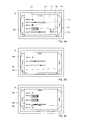
- Figs. 2a-2c present three neighbouring faces 16a-16c of the prismatic GUI according to the invention in three working states. For each face a different functional group of control parameters of the electronic device 2 is assigned. The name of each group is visualized on a given face as a label.
- an active face 16b comprises control parameters belonging to the group denoted as ITEM b.
- the ITEM b group comprises six control items labelled ITEM b1-b6.
- the neighbouring faces 16a and 16c comprise labels indicating the names of the functional groups of control parameters assigned thereto, i.e. ITEM a and ITEM c respectively.
- the neighbouring faces 16a and 16c may also comprise brief information representing the set of control parameters assigned to that face, complete or reduced set of control items distributed on that face or even information about further invisible faces.
- the user instructs the image generating means 9 to change the appearance of the interface 15 and the interface rotates leftward, so that the face 16c with group labelled ITEM c becomes an active face ( Fig. 2b ). On the left side it is now neighboured by previously active face 16b and on the right side it is neighboured by the previously not visualised face 16d.
- Fig. 3 shows the prismatic interface 15 shown in Fig. 2 in a transitional state between two neighbouring working positions, which takes place in response to the user instructions to change its appearance.
- the interface virtually rotates around the central axis 151 in order to switch the active face to a given neighbouring one, wherein the rotation stops in predetermined points located on lines perpendicular to the faces which cross its centres. From a user perspective the rotation resembles rotation of a natural hexagonal prism and is highly intuitive.
- the panel 18 comprises keys enabling a user for inputting instructions to switch to another face 16 and change the state of particular control items 17.
- Two keys 181 labelled with rounded arrows are used to effect rotation of the interface prism 15, two keys 182 labelled with up- and down-arrows enable user to switch focus to subsequent control item displayed on active face, key 183 is used to display suitable context help menu related with currently active focused control item 17, key 184 is "Zoom" button for zooming a view on the interface 15, while two keys 185 labelled with left- and right-arrows effect the change of state (eg. increase/decrease, on/off) of focused control item 17.
- the control panel 18 may also have special keys such as zoom in, zoom out, help button etc.
- Obviously instructions to rotate the prism 15 and to change the state of particular control items 17 may be introduced via computer keyboard as shortcuts or, using gesture recognition technology, via appropriate input devices (such as touch screen).
Abstract
The invention relates to a controlling system for an electronic device having graphical output means (13) for displaying control parameters of said electronic device, image generating means for generating polyhedral graphical user interface which is being projected to a user on said graphical output means (13), input means (12) for inputting instructions from a user, said instructions comprising instructions to change said control parameters of said electronic device and instructions to change the appearance of said polyhedral graphical user interface. In order to make the system more intuitive for a user the polyhedral graphical user interface has a form of a right, regular prism (15) having five to ten faces (16) provided with control items and is rotatable around the central axis (151) thereof, wherein in a working state during inputting instructions to change the state of said control items, an active face (16) of said prismatic graphical user interface is projected on said graphical output means (13) as distortion-free solid body along with neighbouring faces for a viewpoint located outside of said prismatic graphical user interface (15) on a line perpendicular to said active face (16) and substantially in the centre thereof, while in response to an instruction to change the appearance of said prismatic graphical user interface (15), it rotates and is projected to the user on said graphical output means (13) in perspective view, and wherein said control parameters of said electronic device (2) are divided into functional groups, and each of said functional groups is assigned to a group of control items (17) of particular faces of said prismatic graphical user interface.
Description
- The present invention relates to a controlling system for an electronic device having graphical output means for displaying control parameters of said electronic device, image generating means for generating polyhedral graphical user interface which is being projected to a user on said graphical output means, input means for inputting instructions from a user, said instructions comprising instructions to change said control parameters of said electronic device and instructions to change the appearance of said polyhedral graphical user interface.
- In order to facilitate user control of auxiliary electronic devices many forms of interfaces have been proposed so far. Most of them have a form of graphical user interfaces (GUI), many of which are presented on a flat display in 3 dimensions (with a so called Z-axis).
- For example patent publication
US 5515486 discloses a computer-implemented method for directing a computer system to independently rotate a polyhedron display container about several axes. The method includes the steps of displaying a panel container on a display and, in response to a first command from user controls to select a first front panel in the panel container, horizontally rotating the first front panel to a central column if the first front panel is not in the central column. The method also includes the step of in response to the first command to select a second front panel, vertically rotating the second front panel to the central row if the second front panel is not in the central row. - Patent application
US 2003156146 discloses a mobile device comprising processing means for presenting on a display a three-dimensional polyhedron as graphical user interface. Different pieces of information that are to be presented to a user of the mobile device are associated to different facets of this polyhedron, and the visible facets of the polyhedron present at least a hint on a respectively associated piece of information to a user of the mobile device. The mobile device comprises means for enabling a user to cause the processing means to rotate the facets of the presented polyhedron. - Yet another methods and systems of this kind are disclosed in documents
US 2007164989 ,US 2001028369 ,WO 2007008489 ,US 7134095 andUS 6628313 . - Nonetheless many of the prior art solutions have certain drawbacks such as fear of a user to misuse the GUI or accidentally damage the device being controlled, which results mainly from artificial mechanisms employed in GUI known from the state of art. These drawbacks are further related with an increasing number of parameters of the device being controlled and difficult access to these parameters.
- It is an object of the present invention to provide a controlling system with a polyhedral graphical user interface which would be more intuitive for a user by resembling solutions that have been commonly used so far in non-computational applications and nature.
- In order to accomplish the aforementioned and other objects it is provided a controlling system with a polyhedral graphical user interface which has a form of a right, regular prism having five to ten, preferably six, faces provided with control items and is rotatable around the central axis thereof. In a working state, during inputting instructions to change the state of said control items, an active face of said prism is projected on said graphical output means as distortion-free solid body along with neighbouring faces for a viewpoint located outside of said prismatic graphical user interface on a line perpendicular to said active face and substantially in the centre thereof, while in response to an instruction to change the appearance of said prismatic graphical user interface, it rotates and is projected to the user on said graphical output means in perspective view. Said control parameters of said electronic device are in turn divided into functional groups, and each of said functional groups is assigned to a group of control items of particular faces of said prismatic graphical user interface.
- Since the prism of the graphical user interface is not subjected to perspective graphical deformation (i.e. the graphical perspective of the displayed prism corresponds to the visual perspective of the prism as it would have appeared to the user's eye), for a user it is perceived as a honeycombed structure giving him an impression of reliable, natural and thus friendly solution.
- Proper distribution of the parameters according to their functionality makes the interface according to the invention even more intuitive for the user.
- The interface according to the invention may be used as desktop in multitasking computer operating system, to control home automation, etc.
- These and other features of the invention shall be presented below in exemplary embodiments and in connection with the attached drawings on which:
-
Fig. 1 schematically shows an exemplary computer system implementing a controlling system according to the present invention; -
Fig. 2 shows an exemplary prismatic graphical user interface in three normal working states, and -
Fig.3 shows a prismatic graphical user interface in neighbouring states in a transitional, rotating state with an additional control panel. -
Fig. 1 schematically presents an embodiment of the invention in which both the controlling system 1 along with a controlledelectronic device 2 are connected via a system bus of a single integrated computer system 3. - The computer system comprises at least one
processor 4, a working memory 5 (such as DRAM), apermanent memory 6 such asdisc storage 61,optical storage 62 and so forth, and aprocessor 4 that are connected with along with the other elements of the device 1 viasystem bus 7. Theworking memory 5 after booting up the system 3 may store anoperating system 8, image generatingsoftware 9 as well asother programs 10. The skilled technician shall be aware however that each of the software components of the system may also be stored entirely or partially inpermanent memory 6. - Although in this example the controlling system 1 and the controlled
electronic device 2 share some hardware components, such asprocessor 4,working memory 5 andpermanent memory 6, for a skilled person it shall be obvious that the controlledelectronic device 2 may be an external or auxiliary component for the system 1 such as electronically connected (e.g. via a microcontroller) home automation (a so called domotics) system controlling house heating, ventilation and A/C (HVAC), lighting, security, etc. - The controlling system 1 further comprises a communication input/
output interface 11 which enables to link the device 1 (e.g. via a cable, Bluetooth, computer network, etc.) with other devices. The I/O interface 11 receives data introduced viainput devices 12 such askeyboard 121,computer mouse 122, etc. and outputs data e.g. ongraphical output devices 13 such as LCD orCRT display 14. Obviouslygraphical output devices 13 may also be employed as input devices, e.g. in a form of a so called touch-screen. - When the controlling system 1 is in operation, image generating means 9 generate an image of a prismatic graphical user interface and project it on the graphical output means 13. The interface itself is coded in a binary form and stored in the
working memory 10 of the controlling system 1. The binary data is processed by image generating means 9 in response to instructions inputted through the input means 12. - An exemplary prismatic
graphical user interface 15 is shown inFig. 2 in a normal working state. The interface has a form of a right, regular prism having six rectangular faces 16. - To each face of the prism a predetermined set of control parameters of said
electronic device 2 is assigned. The control parameters are visualised on the faces 16 ascontrol items 17 such assliders 171,buttons 172,radio buttons 173,check boxes 174, drop downlists 175, edit boxes, etc. Persons skilled in the art shall be aware of many possibilities to visualise thecontrol items 17 according to the function and state (such us Boolean (on/off), real values range, string lists, etc.) of the control parameters of thedevice 2. - After inputting appropriate instructions enabling for choosing particular face 16, which shall be described in detail later with reference to
Fig. 3 , and projecting the active face, the user may input instructions to change the values of thecontrol items 17 using input means 12. - A change of the graphical representations of the
control items 17 of theinterface 15 in effect change said control parameters of the controlledelectronic device 2 as all changes made to thecontrol item 17 are transmitted to the controlledelectronic device 2 and physically change their state and/or a way of operation. The change of state of given control parameter may take place immediately after the change of state ofparticular control item 17, after accepting all the changes with regard to the given functional group ofcontrol item 17 by e.g. pressing appropriate button or receiving user's instruction to switch to neighbouring face. - In a working state of the
GUI 15, as described above, an active face 16 is projected by generatingmeans 9 for a viewpoint located outside of the GUI on a line perpendicular to the active face 16 and substantially in the centre of the active face 16. The active face is projected as distortion-free solid body so that the neighbouring faces surrounding the active face are visualised in the perspective projection as a trapezoids. In this working state three and only three faces are visible: active face and two neighbouring faces. -
Figs. 2a-2c present three neighbouringfaces 16a-16c of the prismatic GUI according to the invention in three working states. For each face a different functional group of control parameters of theelectronic device 2 is assigned. The name of each group is visualized on a given face as a label. - In the view presented on
Fig. 2a anactive face 16b comprises control parameters belonging to the group denoted as ITEM b. The ITEM b group comprises six control items labelled ITEM b1-b6. The neighbouringfaces - The neighbouring
faces - In order to change any of control parameters assigned e.g. to group ITEM c the user instructs the image generating means 9 to change the appearance of the
interface 15 and the interface rotates leftward, so that theface 16c with group labelled ITEM c becomes an active face (Fig. 2b ). On the left side it is now neighboured by previouslyactive face 16b and on the right side it is neighboured by the previously not visualisedface 16d. - Further leftward rotation of the
prism 15 shall revealfurther faces 16d (Fig. 2c ) and so forth until after six consecutive rotations theface 16b shall again become the active face. -
Fig. 3 shows theprismatic interface 15 shown inFig. 2 in a transitional state between two neighbouring working positions, which takes place in response to the user instructions to change its appearance. - In this transitional the interface virtually rotates around the
central axis 151 in order to switch the active face to a given neighbouring one, wherein the rotation stops in predetermined points located on lines perpendicular to the faces which cross its centres. From a user perspective the rotation resembles rotation of a natural hexagonal prism and is highly intuitive. - Furthermore, in this rotational movement
internal sides certain faces - At the bottom of the
interface 15 anadditional control panel 18 is displayed. Thepanel 18 comprises keys enabling a user for inputting instructions to switch to another face 16 and change the state ofparticular control items 17. - Two
keys 181 labelled with rounded arrows are used to effect rotation of theinterface prism 15, twokeys 182 labelled with up- and down-arrows enable user to switch focus to subsequent control item displayed on active face, key 183 is used to display suitable context help menu related with currently active focusedcontrol item 17,key 184 is "Zoom" button for zooming a view on theinterface 15, while twokeys 185 labelled with left- and right-arrows effect the change of state (eg. increase/decrease, on/off) offocused control item 17. Thecontrol panel 18 may also have special keys such as zoom in, zoom out, help button etc. - Obviously instructions to rotate the
prism 15 and to change the state ofparticular control items 17 may be introduced via computer keyboard as shortcuts or, using gesture recognition technology, via appropriate input devices (such as touch screen). - The above embodiments of the present invention are merely exemplary. The figures are not necessarily to scale and some features may be exaggerated or minimized. These and other factors however should not be considered as limiting the spirit of the invention, the intended scope of protection of which is indicated in appended claims.
Claims (4)
- A controlling system (1) for an electronic device (2) having graphical output means (13) for displaying control parameters of said electronic device (2),
image generating means (9) for generating polyhedral graphical user interface which is being projected to a user on said graphical output means (13), input means (12) for inputting instructions from a user, said instructions comprising instructions to change said control parameters of said electronic device (2) and instructions to change the appearance of said polyhedral graphical user interface,
characterised in that,
the polyhedral graphical user interface has a form of a right, regular prism (15) having five to ten faces (16) provided with control items (17) and is rotatable around the central axis (151) thereof, wherein
in a working state, during inputting instructions to change the state of said control items (17), an active face (16) of said prism is projected on said graphical output means (13) as distortion-free solid body along with neighbouring faces for a viewpoint located outside of said prismatic graphical user interface (15) on a line perpendicular to said active face (16) and substantially in the centre thereof, while
in response to an instruction to change the appearance of said prismatic graphical user interface (15), it rotates and is projected to the user on said graphical output means (13) in perspective view, and wherein
said control parameters of said electronic device (2) are divided into functional groups, and each of said functional groups is assigned to a group of control items (17) of particular faces of said prismatic graphical user interface. - A controlling system according to Claim 1, characterised in that said prism (15) of the polyhedral graphical user interface has six faces (16).
- A controlling system according to Claim 1 or 2, characterised in that in said perspective view of said prismatic graphical user interface (15) the information about the content of the hidden faces (16) is displayed on internal sides (161) thereof.
- A controlling system according to any of preceding Claims, characterised in that said instruction to rotate the prism of said prismatic graphical user interface (15) and/or said instruction to change the state of particular control items (17) is inputted from a user using gesture recognition technology.
Priority Applications (1)
| Application Number | Priority Date | Filing Date | Title |
|---|---|---|---|
| EP10460008A EP2363792A1 (en) | 2010-03-02 | 2010-03-02 | A controlling system with a polyhedral graphical user interface |
Applications Claiming Priority (1)
| Application Number | Priority Date | Filing Date | Title |
|---|---|---|---|
| EP10460008A EP2363792A1 (en) | 2010-03-02 | 2010-03-02 | A controlling system with a polyhedral graphical user interface |
Publications (1)
| Publication Number | Publication Date |
|---|---|
| EP2363792A1 true EP2363792A1 (en) | 2011-09-07 |
Family
ID=42312670
Family Applications (1)
| Application Number | Title | Priority Date | Filing Date |
|---|---|---|---|
| EP10460008A Withdrawn EP2363792A1 (en) | 2010-03-02 | 2010-03-02 | A controlling system with a polyhedral graphical user interface |
Country Status (1)
| Country | Link |
|---|---|
| EP (1) | EP2363792A1 (en) |
Cited By (5)
| Publication number | Priority date | Publication date | Assignee | Title |
|---|---|---|---|---|
| WO2013184293A1 (en) * | 2012-06-08 | 2013-12-12 | Honeywell International Inc. | Context based desktop environment for controlling physical systems |
| WO2014182086A1 (en) * | 2013-05-10 | 2014-11-13 | Samsung Electronics Co., Ltd. | Display apparatus and user interface screen providing method thereof |
| CN104750399A (en) * | 2013-12-27 | 2015-07-01 | 华为技术有限公司 | Controlling method and device of identity displaying |
| DE102015218740A1 (en) | 2015-09-29 | 2017-03-30 | Siemens Aktiengesellschaft | User interface and method for interactive selection of a display |
| CN112448825A (en) * | 2019-08-30 | 2021-03-05 | 腾讯科技(深圳)有限公司 | Session creation method, device, terminal and storage medium |
Citations (16)
| Publication number | Priority date | Publication date | Assignee | Title |
|---|---|---|---|---|
| US5515486A (en) | 1994-12-16 | 1996-05-07 | International Business Machines Corporation | Method, apparatus and memory for directing a computer system to display a multi-axis rotatable, polyhedral-shape panel container having front panels for displaying objects |
| US5678015A (en) * | 1995-09-01 | 1997-10-14 | Silicon Graphics, Inc. | Four-dimensional graphical user interface |
| US5880733A (en) * | 1996-04-30 | 1999-03-09 | Microsoft Corporation | Display system and method for displaying windows of an operating system to provide a three-dimensional workspace for a computer system |
| US6005579A (en) * | 1996-04-30 | 1999-12-21 | Sony Corporation Of America | User interface for displaying windows on a rectangular parallelepiped |
| EP1014257A1 (en) * | 1997-08-12 | 2000-06-28 | Matsushita Electric Industrial Co., Ltd. | Window display |
| US6184884B1 (en) * | 1995-10-02 | 2001-02-06 | Sony Corporation | Image controlling device and image controlling method for displaying a plurality of menu items |
| US20010028369A1 (en) | 2000-03-17 | 2001-10-11 | Vizible.Com Inc. | Three dimensional spatial user interface |
| US20030156146A1 (en) | 2002-02-20 | 2003-08-21 | Riku Suomela | Graphical user interface for a mobile device |
| US6628313B1 (en) | 1998-08-31 | 2003-09-30 | Sharp Kabushiki Kaisha | Information retrieval method and apparatus displaying together main information and predetermined number of sub-information related to main information |
| US7134095B1 (en) | 1999-10-20 | 2006-11-07 | Gateway, Inc. | Simulated three-dimensional navigational menu system |
| WO2007008489A2 (en) | 2005-07-06 | 2007-01-18 | Gemini Mobile Technologies, Inc. | Three-dimensional graphical user interface |
| US20070164989A1 (en) | 2006-01-17 | 2007-07-19 | Ciaran Thomas Rochford | 3-Dimensional Graphical User Interface |
| US20080134086A1 (en) * | 2006-12-01 | 2008-06-05 | Institute For Information Industry | User interface apparatus, method, and computer readable medium thereof |
| US20080141181A1 (en) * | 2006-12-07 | 2008-06-12 | Kabushiki Kaisha Toshiba | Information processing apparatus, information processing method, and program |
| EP1983415A1 (en) * | 2007-04-20 | 2008-10-22 | LG Electronics Inc. | Mobile terminal and screen displaying method thereof |
| WO2010012097A1 (en) * | 2008-07-29 | 2010-02-04 | Bce Inc. | An integrated media player/navigation control tool |
-
2010
- 2010-03-02 EP EP10460008A patent/EP2363792A1/en not_active Withdrawn
Patent Citations (16)
| Publication number | Priority date | Publication date | Assignee | Title |
|---|---|---|---|---|
| US5515486A (en) | 1994-12-16 | 1996-05-07 | International Business Machines Corporation | Method, apparatus and memory for directing a computer system to display a multi-axis rotatable, polyhedral-shape panel container having front panels for displaying objects |
| US5678015A (en) * | 1995-09-01 | 1997-10-14 | Silicon Graphics, Inc. | Four-dimensional graphical user interface |
| US6184884B1 (en) * | 1995-10-02 | 2001-02-06 | Sony Corporation | Image controlling device and image controlling method for displaying a plurality of menu items |
| US5880733A (en) * | 1996-04-30 | 1999-03-09 | Microsoft Corporation | Display system and method for displaying windows of an operating system to provide a three-dimensional workspace for a computer system |
| US6005579A (en) * | 1996-04-30 | 1999-12-21 | Sony Corporation Of America | User interface for displaying windows on a rectangular parallelepiped |
| EP1014257A1 (en) * | 1997-08-12 | 2000-06-28 | Matsushita Electric Industrial Co., Ltd. | Window display |
| US6628313B1 (en) | 1998-08-31 | 2003-09-30 | Sharp Kabushiki Kaisha | Information retrieval method and apparatus displaying together main information and predetermined number of sub-information related to main information |
| US7134095B1 (en) | 1999-10-20 | 2006-11-07 | Gateway, Inc. | Simulated three-dimensional navigational menu system |
| US20010028369A1 (en) | 2000-03-17 | 2001-10-11 | Vizible.Com Inc. | Three dimensional spatial user interface |
| US20030156146A1 (en) | 2002-02-20 | 2003-08-21 | Riku Suomela | Graphical user interface for a mobile device |
| WO2007008489A2 (en) | 2005-07-06 | 2007-01-18 | Gemini Mobile Technologies, Inc. | Three-dimensional graphical user interface |
| US20070164989A1 (en) | 2006-01-17 | 2007-07-19 | Ciaran Thomas Rochford | 3-Dimensional Graphical User Interface |
| US20080134086A1 (en) * | 2006-12-01 | 2008-06-05 | Institute For Information Industry | User interface apparatus, method, and computer readable medium thereof |
| US20080141181A1 (en) * | 2006-12-07 | 2008-06-12 | Kabushiki Kaisha Toshiba | Information processing apparatus, information processing method, and program |
| EP1983415A1 (en) * | 2007-04-20 | 2008-10-22 | LG Electronics Inc. | Mobile terminal and screen displaying method thereof |
| WO2010012097A1 (en) * | 2008-07-29 | 2010-02-04 | Bce Inc. | An integrated media player/navigation control tool |
Non-Patent Citations (1)
| Title |
|---|
| MILLER, G. A.: "The magical number seven, plus or minus two: Some limits on our capacity for processing information", PSYCHOLOGICAL REVIEW, vol. 101, no. 2, 4 May 1955 (1955-05-04), pages 343 - 352, XP002592495, Retrieved from the Internet <URL:http://www.psych.utoronto.ca/users/peterson/psy430s2001/Miller%20GA%20Magical%20Seven%20Psych%20Review%201955.pdf> [retrieved on 20100719] * |
Cited By (9)
| Publication number | Priority date | Publication date | Assignee | Title |
|---|---|---|---|---|
| WO2013184293A1 (en) * | 2012-06-08 | 2013-12-12 | Honeywell International Inc. | Context based desktop environment for controlling physical systems |
| WO2014182086A1 (en) * | 2013-05-10 | 2014-11-13 | Samsung Electronics Co., Ltd. | Display apparatus and user interface screen providing method thereof |
| US9247303B2 (en) | 2013-05-10 | 2016-01-26 | Samsung Electronics Co., Ltd. | Display apparatus and user interface screen providing method thereof |
| CN104750399A (en) * | 2013-12-27 | 2015-07-01 | 华为技术有限公司 | Controlling method and device of identity displaying |
| CN104750399B (en) * | 2013-12-27 | 2018-10-30 | 华为技术有限公司 | Identify the control method and device of display |
| DE102015218740A1 (en) | 2015-09-29 | 2017-03-30 | Siemens Aktiengesellschaft | User interface and method for interactive selection of a display |
| US10739942B2 (en) | 2015-09-29 | 2020-08-11 | Siemens Aktiengesellschaft | User interface and method for interactively selecting a display |
| CN112448825A (en) * | 2019-08-30 | 2021-03-05 | 腾讯科技(深圳)有限公司 | Session creation method, device, terminal and storage medium |
| CN112448825B (en) * | 2019-08-30 | 2022-03-15 | 腾讯科技(深圳)有限公司 | Session creation method, device, terminal and storage medium |
Similar Documents
| Publication | Publication Date | Title |
|---|---|---|
| US10521579B2 (en) | Implementation of biometric authentication | |
| US20220091722A1 (en) | Devices, methods, and graphical user interfaces for interacting with three-dimensional environments | |
| EP2996015B1 (en) | Method to use augmented reality to function as hmi display | |
| US9182838B2 (en) | Depth camera-based relative gesture detection | |
| EP3745303A1 (en) | Implementation of biometric authentication with error condition detection and display of an error indication | |
| EP3528173A1 (en) | Implementation of biometric authentication with detection and display of an error indication | |
| EP2363792A1 (en) | A controlling system with a polyhedral graphical user interface | |
| WO2005069112A2 (en) | Method and apparatus for interfacing with a graphical user interface using a control interface | |
| US20170052701A1 (en) | Dynamic virtual keyboard graphical user interface | |
| US20140253432A1 (en) | Sensor-monitored, 3d, interactive holographic freespace control unit (hfcu) and associated components | |
| US20190026004A1 (en) | Three Dimensional Icons for Computer Applications | |
| KR102021851B1 (en) | Method for processing interaction between object and user of virtual reality environment | |
| WO2019166005A1 (en) | Smart terminal, sensing control method therefor, and apparatus having storage function | |
| KR20230047172A (en) | Video call interaction method and device | |
| US11016588B2 (en) | Method and device and system with dual mouse support | |
| CN106200900A (en) | Based on identifying that the method and system that virtual reality is mutual are triggered in region in video | |
| US20230106627A1 (en) | Devices, Methods, And Graphical User Interfaces for Interacting with Three-Dimensional Environments | |
| JP5767371B1 (en) | Game program for controlling display of objects placed on a virtual space plane | |
| TW202328872A (en) | Metaverse content modality mapping | |
| JP6130583B1 (en) | Computer program for controlling objects in virtual space and computer-implemented method | |
| US20190346968A1 (en) | Projected, interactive environment | |
| JP2016016319A (en) | Game program for display-controlling objects arranged on virtual spatial plane | |
| Tumkor et al. | Hand gestures in CAD systems | |
| Seth et al. | A low cost virtual reality human computer interface for CAD model manipulation | |
| AU2019201101C1 (en) | Implementation of biometric authentication |
Legal Events
| Date | Code | Title | Description |
|---|---|---|---|
| PUAI | Public reference made under article 153(3) epc to a published international application that has entered the european phase |
Free format text: ORIGINAL CODE: 0009012 |
|
| AK | Designated contracting states |
Kind code of ref document: A1 Designated state(s): AT BE BG CH CY CZ DE DK EE ES FI FR GB GR HR HU IE IS IT LI LT LU LV MC MK MT NL NO PL PT RO SE SI SK SM TR |
|
| AX | Request for extension of the european patent |
Extension state: AL BA ME RS |
|
| STAA | Information on the status of an ep patent application or granted ep patent |
Free format text: STATUS: THE APPLICATION IS DEEMED TO BE WITHDRAWN |
|
| 18D | Application deemed to be withdrawn |
Effective date: 20120308 |