EP2364252B1 - Method and apparatus for packaging a product in a package with tray and sleeve - Google Patents
Method and apparatus for packaging a product in a package with tray and sleeve Download PDFInfo
- Publication number
- EP2364252B1 EP2364252B1 EP09748463.8A EP09748463A EP2364252B1 EP 2364252 B1 EP2364252 B1 EP 2364252B1 EP 09748463 A EP09748463 A EP 09748463A EP 2364252 B1 EP2364252 B1 EP 2364252B1
- Authority
- EP
- European Patent Office
- Prior art keywords
- mandrel
- plastics
- film
- tray
- sleeve
- Prior art date
- Legal status (The legal status is an assumption and is not a legal conclusion. Google has not performed a legal analysis and makes no representation as to the accuracy of the status listed.)
- Not-in-force
Links
Images


Classifications
-
- B—PERFORMING OPERATIONS; TRANSPORTING
- B65—CONVEYING; PACKING; STORING; HANDLING THIN OR FILAMENTARY MATERIAL
- B65D—CONTAINERS FOR STORAGE OR TRANSPORT OF ARTICLES OR MATERIALS, e.g. BAGS, BARRELS, BOTTLES, BOXES, CANS, CARTONS, CRATES, DRUMS, JARS, TANKS, HOPPERS, FORWARDING CONTAINERS; ACCESSORIES, CLOSURES, OR FITTINGS THEREFOR; PACKAGING ELEMENTS; PACKAGES
- B65D77/00—Packages formed by enclosing articles or materials in preformed containers, e.g. boxes, cartons, sacks or bags
- B65D77/003—Articles enclosed in rigid or semi-rigid containers, the whole being wrapped
-
- B—PERFORMING OPERATIONS; TRANSPORTING
- B65—CONVEYING; PACKING; STORING; HANDLING THIN OR FILAMENTARY MATERIAL
- B65B—MACHINES, APPARATUS OR DEVICES FOR, OR METHODS OF, PACKAGING ARTICLES OR MATERIALS; UNPACKING
- B65B11/00—Wrapping, e.g. partially or wholly enclosing, articles or quantities of material, in strips, sheets or blanks, of flexible material
-
- B—PERFORMING OPERATIONS; TRANSPORTING
- B65—CONVEYING; PACKING; STORING; HANDLING THIN OR FILAMENTARY MATERIAL
- B65B—MACHINES, APPARATUS OR DEVICES FOR, OR METHODS OF, PACKAGING ARTICLES OR MATERIALS; UNPACKING
- B65B7/00—Closing containers or receptacles after filling
- B65B7/16—Closing semi-rigid or rigid containers or receptacles not deformed by, or not taking-up shape of, contents, e.g. boxes or cartons
- B65B7/28—Closing semi-rigid or rigid containers or receptacles not deformed by, or not taking-up shape of, contents, e.g. boxes or cartons by applying separate preformed closures, e.g. lids, covers
-
- B—PERFORMING OPERATIONS; TRANSPORTING
- B65—CONVEYING; PACKING; STORING; HANDLING THIN OR FILAMENTARY MATERIAL
- B65B—MACHINES, APPARATUS OR DEVICES FOR, OR METHODS OF, PACKAGING ARTICLES OR MATERIALS; UNPACKING
- B65B9/00—Enclosing successive articles, or quantities of material, e.g. liquids or semiliquids, in flat, folded, or tubular webs of flexible sheet material; Subdividing filled flexible tubes to form packages
- B65B9/10—Enclosing successive articles, or quantities of material, in preformed tubular webs, or in webs formed into tubes around filling nozzles, e.g. extruded tubular webs
-
- B—PERFORMING OPERATIONS; TRANSPORTING
- B31—MAKING ARTICLES OF PAPER, CARDBOARD OR MATERIAL WORKED IN A MANNER ANALOGOUS TO PAPER; WORKING PAPER, CARDBOARD OR MATERIAL WORKED IN A MANNER ANALOGOUS TO PAPER
- B31B—MAKING CONTAINERS OF PAPER, CARDBOARD OR MATERIAL WORKED IN A MANNER ANALOGOUS TO PAPER
- B31B70/00—Making flexible containers, e.g. envelopes or bags
- B31B70/26—Folding sheets, blanks or webs
- B31B70/261—Folding sheets, blanks or webs involving transversely folding, i.e. along a line perpendicular to the direction of movement
-
- B—PERFORMING OPERATIONS; TRANSPORTING
- B65—CONVEYING; PACKING; STORING; HANDLING THIN OR FILAMENTARY MATERIAL
- B65B—MACHINES, APPARATUS OR DEVICES FOR, OR METHODS OF, PACKAGING ARTICLES OR MATERIALS; UNPACKING
- B65B25/00—Packaging other articles presenting special problems
-
- B—PERFORMING OPERATIONS; TRANSPORTING
- B65—CONVEYING; PACKING; STORING; HANDLING THIN OR FILAMENTARY MATERIAL
- B65B—MACHINES, APPARATUS OR DEVICES FOR, OR METHODS OF, PACKAGING ARTICLES OR MATERIALS; UNPACKING
- B65B7/00—Closing containers or receptacles after filling
- B65B7/16—Closing semi-rigid or rigid containers or receptacles not deformed by, or not taking-up shape of, contents, e.g. boxes or cartons
- B65B7/28—Closing semi-rigid or rigid containers or receptacles not deformed by, or not taking-up shape of, contents, e.g. boxes or cartons by applying separate preformed closures, e.g. lids, covers
- B65B7/2842—Securing closures on containers
- B65B7/2878—Securing closures on containers by heat-sealing
Definitions
- This invention relates to a packaging system and in particular to a method of packaging prepared food.
- FIG. 1 depicts such a conventional food tray arrangement comprising a conventional food tray 1 made from an appropriate plastics material, which after filling with product 3 is covered and sealed with a suitable plastic film 2.
- a cardboard outer cover 4 is slid over the sealed tray to provide the outer covering.
- Such an arrangement is disclosed in 4 221 320 A.
- the customer will often slide aside the cardboard sleeve to view the product.
- the cardboard outer sleeve could be provided with a window, or an aperture could be cut in the sleeve to provide viewing of the contents, this adds to the cost of production.
- the cardboard outer is itself relatively expensive and it is an expensive process by which it is fitted to the food tray, usually involving manual labour. Printing of product specific data such as date and batch number is typically carried out before the cardboard sleeve is brought to the food tray for fitting, which can result in errors and wastage.
- the cardboard outer is easily removed in the supermarket or any store, and the enclosed plastic tray with its transparent cover can be inserted into the cardboard outer of a lower cost product which has the same physical dimensions, in order to defraud the retailer. If this is not noticed at the check-out, a lower price will be paid than the product should command. There is also the risk that important food allergy information that appears on the cardboard sleeve may not be available to the customer if the cardboard sleeve is removed or substituted, which could be potentially life-threatening.
- the present invention provides a method for packaging a product according to claim 1.
- the method of the invention provides a package for a product, such as pre-prepared food.
- the package comprises a plastics tray for containing the product.
- the tray is sealed by a transparent plastics membrane.
- a plastics sleeve encloses the tray.
- the plastics sleeve covers the plastics membrane substantially completely in the assembled package.
- the package made according to the method of the invention has the advantage that it can be made less expensive, more recyclable and with enhanced visibility of the contained product than for existing packaging.
- the product to be packaged may be a pre-prepared food product, such as a "ready meal".
- the packaging of the invention may be applied to a wide range of products, including cosmetics or paint, for example.
- the plastics sleeve may be, at least partially, transparent. In this way, the plastics sleeve can allow the customer to view the content of the package, for example through a window defined in the sleeve.
- the plastics sleeve may be printed. Typically, the printing on the plastics sleeve will obscure some of the product that would otherwise be visible through the transparent membrane.
- the plastics sleeve is formed as a loop of plastics film material joined at its two ends.
- the amount of the overlap between the two ends may be selected according to the desired characteristics of the package.
- the ends of the loop of plastics sheet material may be ultrasonically bonded together.
- other bonding methods may be used, such as adhesive bonding or heat sealing.
- ultrasonic bonding is preferred as it is quick and has only a minimal effect on the appearance of the film.
- the tray may be generally rectangular in plan, but this is not intended to be restrictive.
- the tray may be circular, hemispherical or generally bowl-shaped.
- the tray is of plastics material, as this facilitates recyclability.
- the tray may be formed of other material, such as metal foil, molded paper pulp or cardboard.
- the mandrel will be approximately the same size and shape as the tray in order that the plastics sleeve is a good fit around the tray.
- the step of forming the plastics sleeve about the mandrel may comprise wrapping a film of plastics material around the mandrel and bonding the film material to itself.
- the bonding step may involve ultrasonic bonding of the film material to itself.
- the plastics film may be provided on a continuous roll.
- the step of wrapping the film around the mandrel may include rotating the mandrel relative to the film to wind the film around the mandrel.
- the plastics sleeve may be held on the mandrel during forming by a vacuum system.
- the plastics sleeve may be removed from the mandrel during forming by a vacuum system.
- removing the plastics sleeve from the mandrel and sliding the plastics sleeve onto the sealed tray may include transferring the plastics sleeve directly from the mandrel to the sealed tray.
- the invention further provides a packaging machine as defined in claim 10.
- Figure 2 depicts a packaging product made according to an embodiment of the present invention.
- the product comprises a food tray 1 made from an appropriate plastics material.
- the food tray 1 is filled with a food product 3 and covered and sealed with a suitable plastic film 2.
- a complete loop of a further plastic film 5 with a joint 6 to form the loop is slid over the sealed food tray 1 to provide the outer covering.
- the packaging product made according to the present invention provides a means by which the packaging for prepared meals and similar products can be constructed from materials which can be recycled together.
- the outer plastic sleeve 5 is also much cheaper to apply than a cardboard sleeve and can provide sight of the product contents via a window, if a transparent plastics film is used.
- the security of the overall product is also enhanced because such an outer sleeve 5 is much more difficult to remove and to replace as it collapses and loses its shape when removed from the inner tray 1.
- the process according to an embodiment of the invention uses a supply of plastic trays 1 of the requisite size, complete with contents 3 and sealed with a plastic film 2 in the conventional way.
- the plastics film 2 may be sealed to the tray by ultrasonic welding.
- Figure 3 depicts the overall machine arrangement according to an embodiment of the present invention.
- a conveyor arrangement 7 brings filled sealed food trays 1 in readiness for the outer sleeve 5 to be applied.
- the food tray 1 which is ready for the outer sleeve 5 to be applied is manoeuvred into position opposite a mandrel 8 on which the continuous printed film 9 is wound to form a complete loop.
- the loop which forms the outer sleeve 5 is slid onto the waiting food tray 1, which is then manoeuvred to the exit conveyor 10 to join food trays which have already had the outer sleeve 5 applied.
- Printing, date stamping and data logging can occur at this point prior to the completed product being taken away for bulk packing and distribution.
- the application of product specific data by printing at this point removes the possibility of incorrect marking, and reduces waste.
- the bulk of branding and generic product information will have been pre-printed on the continuous film material which is supplied to the mandrel 8.
- Figure 4 depicts the mandrel 8 which has appropriate dimensions for the food tray 1 to be covered, and is mounted on a rotational shaft 11.
- the mandrel 8 is secured to the shaft 11 at one end, so that the mandrel 8 can rotate about the axis of the shaft 11, which is generally aligned with the longer dimension of the plastic tray 1 (where the plastic tray is rectangular).
- a plastic tray 1, filled with product and sealed, is aligned with the axis of rotation of the mandrel 8.
- a plastics film 9, printed to suit the packaging requirements for the product is fed in continuous form in a direction perpendicular to the rotation shaft.
- a retaining mechanism 12, 13 is provided such that the leading edge of the film 9 can be secured to the mandrel 8.
- the continuous film 9 may be similar or even identical to the film 2 which is used to cover and seal the tray 1.
- the plastics film 9 is 48 micron clear oriented polypropylene (OPP) film.
- OPP micron clear oriented polypropylene
- the film thickness may range from 20 to 100 microns.
- Figure 5 shows the mandrel 8 onto which the continuous film 9 is fed.
- the film 9 is retained in place by a vacuum system 12 which applies a partial vacuum along the length of the leading edge of the film 9 by way of a number of apertures 13 such that the film is retained in position while the mandrel 8 is rotated by the rotational shaft 11 so that a complete loop of film is formed around the mandrel 8.
- the mandrel 8 is rotated about its axis of rotation, such as to completely wrap the mandrel 8 in the film 9.
- the film 9 is marked with an indexing point which is typically identified by optical means. The indexing point ensures that when the film 9 is wrapped around the mandrel 8, the printing on the film and any viewing window are correctly located relative to their final position on the tray 1. In this way, when the film is transferred to the food containing tray 1 from the mandrel 8, the printing and window are correctly positioned for illustrating the product and viewing the contents 3.
- FIG. 6 shows the mandrel 8 with a complete turn of film 9 around it.
- the base plate 14 of an ultrasonic horn 15 is fitted to the mandrel 8 so that it is inside the loop of film 5.
- the ultrasonic horn 15 is moved to make contact with the loop of film 5 and by the application of ultrasonic energy a joint is formed in the film so that it becomes a permanent continuous loop.
- a cutter blade 16 cuts the film at the feed point so that the continuous loop remains on the mandrel 8.
- the ultrasonic horn 15 moves up to the film 9 which is resting on a base blade 14.
- the ultrasonic horn 15 and the base blade 14 coming together forms an ultrasonic weld 6 so that the film forms a complete loop 5.
- the blade 16 cuts the film 9 so that a complete bonded turn of film 5 is left on the mandrel and the surplus film is withdrawn ready for the next time that it is required.
- the film clamping mechanism 12, 13 is then released.
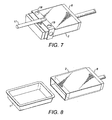
- Figure 7 depicts a vacuum arrangement 17 whereby a partial vacuum is applied through a series of apertures 18 to the top and the two side leading edges of the film loop 5, which is in a continuous loop around the mandrel 8.
- the set of vacuum devices 17 is presented to the film wrapping of the mandrel 8 along the upper and two sides, at the end of the mandrel furthest from the rotation shaft 11, and nearest to the tray 1 filled with product.
- Mandrel 8 is aligned in the same orientation as the food tray 1.
- the arm 17 positions itself over the mandrel 8 and collects the sleeve 5.
- Figure 8 depicts the continuous loop of film 5 sliding from the mandrel 8 on to the food tray 1 to complete the product.
- a package for pre-prepared food comprises a plastics tray 1 for containing a pre-prepared food product 3.
- the tray 1 is sealed by a transparent plastics membrane 2.
- a plastics sleeve 5 encloses the tray 1.
- the plastics sleeve 5 covers the plastics membrane 2 substantially completely in the assembled package.
- a method for packaging pre-prepared food comprises: providing a plastics tray 1 for containing a pre-prepared food product 3, the tray being sealed by a transparent plastics membrane 2; forming a plastics sleeve 5 about a mandrel 8; removing the plastics sleeve 5 from the mandrel 8; and sliding the plastics sleeve 5 onto the sealed plastics tray 1.
- the package is more recyclable and less expensive than know equivalent packaging.
Description
- This invention relates to a packaging system and in particular to a method of packaging prepared food.
- It is known from the prior art for prepared meals ("ready meals") to be packaged in a plastics tray with a covering membrane of transparent plastics. The covering membrane is sealed to the plastics tray, for example with an adhesive. The sealed tray is generally enclosed in a cardboard sleeve on which the details of the contents and instructions for preparation are printed.
Figure 1 depicts such a conventional food tray arrangement comprising aconventional food tray 1 made from an appropriate plastics material, which after filling withproduct 3 is covered and sealed with a suitableplastic film 2. A cardboard outer cover 4 is slid over the sealed tray to provide the outer covering. Such an arrangement is disclosed in 4 221 320 A. - There are a number of problems with such packaging arrangements. Firstly, as the overall package is made up of at least two different materials, the recycling of the packaging is relatively complicated.
- Secondly, it is desirable for the customer to be able to see the product they are buying through the transparent membrane and customers will often slide aside the cardboard sleeve to view the product. While the cardboard outer sleeve could be provided with a window, or an aperture could be cut in the sleeve to provide viewing of the contents, this adds to the cost of production. The cardboard outer is itself relatively expensive and it is an expensive process by which it is fitted to the food tray, usually involving manual labour. Printing of product specific data such as date and batch number is typically carried out before the cardboard sleeve is brought to the food tray for fitting, which can result in errors and wastage.
- Finally, the cardboard outer is easily removed in the supermarket or any store, and the enclosed plastic tray with its transparent cover can be inserted into the cardboard outer of a lower cost product which has the same physical dimensions, in order to defraud the retailer. If this is not noticed at the check-out, a lower price will be paid than the product should command. There is also the risk that important food allergy information that appears on the cardboard sleeve may not be available to the customer if the cardboard sleeve is removed or substituted, which could be potentially life-threatening.
- The present invention at least in its presently preferred embodiments seeks to address at least some of these problems.
US 6,092,664 ,EP 619244 GB 2323836 - The present invention provides a method for packaging a product according to
claim 1. The method of the invention provides a package for a product, such as pre-prepared food. The package comprises a plastics tray for containing the product. The tray is sealed by a transparent plastics membrane. A plastics sleeve encloses the tray. The plastics sleeve covers the plastics membrane substantially completely in the assembled package. - The package made according to the method of the invention has the advantage that it can be made less expensive, more recyclable and with enhanced visibility of the contained product than for existing packaging.
- The product to be packaged may be a pre-prepared food product, such as a "ready meal". However, the packaging of the invention may be applied to a wide range of products, including cosmetics or paint, for example.
- The plastics sleeve may be, at least partially, transparent. In this way, the plastics sleeve can allow the customer to view the content of the package, for example through a window defined in the sleeve. The plastics sleeve may be printed. Typically, the printing on the plastics sleeve will obscure some of the product that would otherwise be visible through the transparent membrane.
- Typically, the plastics sleeve is formed as a loop of plastics film material joined at its two ends. The amount of the overlap between the two ends may be selected according to the desired characteristics of the package.
- Conveniently, the ends of the loop of plastics sheet material may be ultrasonically bonded together. Alternatively, other bonding methods may be used, such as adhesive bonding or heat sealing. However, ultrasonic bonding is preferred as it is quick and has only a minimal effect on the appearance of the film.
- Typically, the tray may be generally rectangular in plan, but this is not intended to be restrictive. For example, the tray may be circular, hemispherical or generally bowl-shaped. In the presently preferred embodiment, the tray is of plastics material, as this facilitates recyclability. However, the tray may be formed of other material, such as metal foil, molded paper pulp or cardboard.
- Typically, the mandrel will be approximately the same size and shape as the tray in order that the plastics sleeve is a good fit around the tray.
- The step of forming the plastics sleeve about the mandrel may comprise wrapping a film of plastics material around the mandrel and bonding the film material to itself. The bonding step may involve ultrasonic bonding of the film material to itself. Conveniently, the plastics film may be provided on a continuous roll.
- In embodiments of the invention, the step of wrapping the film around the mandrel may include rotating the mandrel relative to the film to wind the film around the mandrel. Conveniently, the plastics sleeve may be held on the mandrel during forming by a vacuum system. Similarly, the plastics sleeve may be removed from the mandrel during forming by a vacuum system.
- Advantageously, removing the plastics sleeve from the mandrel and sliding the plastics sleeve onto the sealed tray may include transferring the plastics sleeve directly from the mandrel to the sealed tray.
- The invention further provides a packaging machine as defined in
claim 10. - Embodiments of the invention are further described by way of example only hereinafter with reference to the accompanying drawings, in which:
-
Figure 1 is a schematic view of a food tray arrangement according to the prior art; -
Figure 2 is a schematic view of a food tray arrangement made according to an embodiment of the invention; -
Figure 3 is a schematic plan view of a packaging line in accordance with the present invention; -
Figure 4 is a schematic representation of a mandrel for use in a method according to the invention; -
Figures 5, 6 and7 are schematic representations of the mandrel ofFigure 4 in use; and -
Figure 8 is a schematic representation of the transfer of a plastics sleeve from the mandrel ofFigure 4 to a food tray in accordance with the invention. -
Figure 2 depicts a packaging product made according to an embodiment of the present invention. The product comprises afood tray 1 made from an appropriate plastics material. Thefood tray 1 is filled with afood product 3 and covered and sealed with a suitableplastic film 2. A complete loop of a furtherplastic film 5 with ajoint 6 to form the loop is slid over the sealedfood tray 1 to provide the outer covering. - The packaging product made according to the present invention provides a means by which the packaging for prepared meals and similar products can be constructed from materials which can be recycled together. The outer
plastic sleeve 5 is also much cheaper to apply than a cardboard sleeve and can provide sight of the product contents via a window, if a transparent plastics film is used. The security of the overall product is also enhanced because such anouter sleeve 5 is much more difficult to remove and to replace as it collapses and loses its shape when removed from theinner tray 1. - As a feedstock, the process according to an embodiment of the invention uses a supply of
plastic trays 1 of the requisite size, complete withcontents 3 and sealed with aplastic film 2 in the conventional way. Theplastics film 2 may be sealed to the tray by ultrasonic welding. -
Figure 3 depicts the overall machine arrangement according to an embodiment of the present invention. InFigure 3 aconveyor arrangement 7 brings filled sealedfood trays 1 in readiness for theouter sleeve 5 to be applied. Thefood tray 1 which is ready for theouter sleeve 5 to be applied is manoeuvred into position opposite amandrel 8 on which the continuous printed film 9 is wound to form a complete loop. After jointing, the loop which forms theouter sleeve 5 is slid onto the waitingfood tray 1, which is then manoeuvred to theexit conveyor 10 to join food trays which have already had theouter sleeve 5 applied. Printing, date stamping and data logging can occur at this point prior to the completed product being taken away for bulk packing and distribution. The application of product specific data by printing at this point removes the possibility of incorrect marking, and reduces waste. However, the bulk of branding and generic product information will have been pre-printed on the continuous film material which is supplied to themandrel 8. -
Figure 4 depicts themandrel 8 which has appropriate dimensions for thefood tray 1 to be covered, and is mounted on arotational shaft 11. Themandrel 8 is secured to theshaft 11 at one end, so that themandrel 8 can rotate about the axis of theshaft 11, which is generally aligned with the longer dimension of the plastic tray 1 (where the plastic tray is rectangular). Aplastic tray 1, filled with product and sealed, is aligned with the axis of rotation of themandrel 8. - A plastics film 9, printed to suit the packaging requirements for the product is fed in continuous form in a direction perpendicular to the rotation shaft. A retaining
mechanism mandrel 8. The continuous film 9 may be similar or even identical to thefilm 2 which is used to cover and seal thetray 1. In the presently preferred example, the plastics film 9 is 48 micron clear oriented polypropylene (OPP) film. However, the film thickness may range from 20 to 100 microns. -
Figure 5 shows themandrel 8 onto which the continuous film 9 is fed. The film 9 is retained in place by avacuum system 12 which applies a partial vacuum along the length of the leading edge of the film 9 by way of a number ofapertures 13 such that the film is retained in position while themandrel 8 is rotated by therotational shaft 11 so that a complete loop of film is formed around themandrel 8. - The
mandrel 8 is rotated about its axis of rotation, such as to completely wrap themandrel 8 in the film 9. The film 9 is marked with an indexing point which is typically identified by optical means. The indexing point ensures that when the film 9 is wrapped around themandrel 8, the printing on the film and any viewing window are correctly located relative to their final position on thetray 1. In this way, when the film is transferred to thefood containing tray 1 from themandrel 8, the printing and window are correctly positioned for illustrating the product and viewing thecontents 3. -
Figure 6 shows themandrel 8 with a complete turn of film 9 around it. Thebase plate 14 of anultrasonic horn 15 is fitted to themandrel 8 so that it is inside the loop offilm 5. Theultrasonic horn 15 is moved to make contact with the loop offilm 5 and by the application of ultrasonic energy a joint is formed in the film so that it becomes a permanent continuous loop. At the same time acutter blade 16 cuts the film at the feed point so that the continuous loop remains on themandrel 8. Thus, theultrasonic horn 15 moves up to the film 9 which is resting on abase blade 14. Theultrasonic horn 15 and thebase blade 14 coming together forms anultrasonic weld 6 so that the film forms acomplete loop 5. As thehorn 15 is withdrawn, theblade 16 cuts the film 9 so that a complete bonded turn offilm 5 is left on the mandrel and the surplus film is withdrawn ready for the next time that it is required. Thefilm clamping mechanism -
Figure 7 depicts avacuum arrangement 17 whereby a partial vacuum is applied through a series ofapertures 18 to the top and the two side leading edges of thefilm loop 5, which is in a continuous loop around themandrel 8. The set ofvacuum devices 17 is presented to the film wrapping of themandrel 8 along the upper and two sides, at the end of the mandrel furthest from therotation shaft 11, and nearest to thetray 1 filled with product.Mandrel 8 is aligned in the same orientation as thefood tray 1. Thearm 17 positions itself over themandrel 8 and collects thesleeve 5. Application of a partial vacuum pulls thefilm 5 clear of the surfaces of themandrel 8 such that when thevacuum device 17 is moved in the direction of thefood tray 1, thefilm 5 slides along themandrel 8 and on to thefood tray 1, in such a manner that thefood tray 1 is enclosed, and the orientation of thefilm loop 5 on the tray is maintained. -
Figure 8 depicts the continuous loop offilm 5 sliding from themandrel 8 on to thefood tray 1 to complete the product. - In summary, a package for pre-prepared food comprises a
plastics tray 1 for containing apre-prepared food product 3. Thetray 1 is sealed by atransparent plastics membrane 2. Aplastics sleeve 5 encloses thetray 1. Theplastics sleeve 5 covers theplastics membrane 2 substantially completely in the assembled package. - A method for packaging pre-prepared food comprises: providing a
plastics tray 1 for containing apre-prepared food product 3, the tray being sealed by atransparent plastics membrane 2; forming aplastics sleeve 5 about amandrel 8; removing theplastics sleeve 5 from themandrel 8; and sliding theplastics sleeve 5 onto the sealedplastics tray 1. - The package is more recyclable and less expensive than know equivalent packaging.
- Throughout the description and claims of this specification, the words "comprise" and "contain" and variations of them mean "including but not limited to", and they are not intended to (and do not) exclude other components, integers or steps. Throughout the description and claims of this specification, the singular encompasses the plural unless the context otherwise requires. In particular, where the indefinite article is used, the specification is to be understood as contemplating plurality as well as singularity, unless the context requires otherwise.
Claims (18)
- A method for packaging a product (3), the method comprising:providing a tray (1) containing the product (3), the tray (1) being sealed by a transparent plastics membrane (2),forming a plastics sleeve (5) about a mandrel (8),removing the plastics sleeve (5) from the mandrel (8); andsliding the plastics sleeve (5) onto the sealed tray (1).
- A method as claimed in claim 1, wherein the step of forming the plastics sleeve (5) about the mandrel (8) comprises wrapping a film of plastics material around the mandrel (8) and bonding the film material to itself.
- A method as claimed in claim 2, wherein the bonding step involves ultrasonic bonding of the film material to itself.
- A method as claimed in claim 2 or 3, wherein the plastics film is provided on a continuous roll.
- A method as claimed in claim 4, wherein the plastics sleeve is cut from the continuous roll after the bonding step.
- A method as claimed in any of claims 2 to 5, wherein the step of wrapping the film around the mandrel (8) includes rotating the mandrel (8) relative to the film to wind the film around the mandrel (8).
- A method as claimed in any preceding claim, wherein the plastics sleeve (5) is held on the mandrel (8) during forming by a vacuum system.
- A method as claimed in any preceding claim, wherein the plastics sleeve (5) is removed from the mandrel (8) after forming by a vacuum system.
- A method as claimed in any preceding claim, wherein removing the plastics sleeve (5) from the mandrel (8) and sliding the plastics sleeve (5) onto the sealed tray (1) includes transferring the plastics sleeve directly from the mandrel (8) to the sealed tray (1).
- A packaging machine comprising:a mandrel (8);means for providing a tray (1) containing a product (3), the tray (1) being sealed by a transparent plastics membrane (2);means for forming a plastics sleeve (5) about the mandrel (8);means for removing the plastics sleeve (5) from the mandrel (8); andmeans for sliding the plastics sleeve (5) onto the sealed tray (1)
- A packaging machine as claimed in claim 10, wherein the means for forming the plastics sleeve (5) about the mandrel (8) comprises means for wrapping a film of plastics material around the mandrel (8) and means for bonding the film material to itself.
- A packaging machine as claimed in claim 11, wherein the bonding means comprises means for ultrasonic bonding of the film material to itself.
- A packaging machine as claimed in claim 11 or 12, wherein the plastics film is provided on a continuous roll.
- A packaging machine as claimed in claim 13 comprising means for cutting the plastics sleeve from the continuous roll after bonding.
- A packaging machine as claimed in any of claims 11 to 14, wherein the means for wrapping the film around the mandrel (8) includes means for rotating the mandrel (8) relative to the film to wind the film around the mandrel (8).
- A packaging machine as claimed in any of claims 10 to 15 comprising a vacuum system arranged to hold the plastics sleeve (5) on the mandrel (8) during forming.
- A packaging machine as claimed in any of claims 10 to 16 comprising a vacuum system arranged to remove the plastics sleeve (5) from the mandrel (8) after forming.
- A packaging machine as claimed in any of claims 10 to 17, wherein the means for removing the plastics sleeve (5) from the mandrel (8) and the means for sliding the plastics sleeve (5) onto the sealed tray (1) are arranged to transfer the plastics sleeve directly from the mandrel (8) to the sealed tray (1).
Applications Claiming Priority (2)
| Application Number | Priority Date | Filing Date | Title |
|---|---|---|---|
| GBGB0820148.5A GB0820148D0 (en) | 2008-11-04 | 2008-11-04 | SIB packaging system |
| PCT/GB2009/051483 WO2010052495A1 (en) | 2008-11-04 | 2009-11-04 | Package with tray and sleeve and method for packaging a product |
Publications (2)
| Publication Number | Publication Date |
|---|---|
| EP2364252A1 EP2364252A1 (en) | 2011-09-14 |
| EP2364252B1 true EP2364252B1 (en) | 2014-07-23 |
Family
ID=40138272
Family Applications (1)
| Application Number | Title | Priority Date | Filing Date |
|---|---|---|---|
| EP09748463.8A Not-in-force EP2364252B1 (en) | 2008-11-04 | 2009-11-04 | Method and apparatus for packaging a product in a package with tray and sleeve |
Country Status (7)
| Country | Link |
|---|---|
| US (1) | US20110214396A1 (en) |
| EP (1) | EP2364252B1 (en) |
| CN (1) | CN102202880A (en) |
| BR (1) | BRPI0921646A2 (en) |
| ES (1) | ES2496673T3 (en) |
| GB (1) | GB0820148D0 (en) |
| WO (1) | WO2010052495A1 (en) |
Families Citing this family (3)
| Publication number | Priority date | Publication date | Assignee | Title |
|---|---|---|---|---|
| JP5927326B1 (en) * | 2015-06-12 | 2016-06-01 | 日本碍子株式会社 | Method for producing wound body and method for producing multiple wound body |
| US10301060B2 (en) | 2016-04-29 | 2019-05-28 | Incipio, Llc | Retail product package |
| WO2022005452A1 (en) * | 2020-06-29 | 2022-01-06 | Bemis Company, Inc. | Composite package with mineral oil barrier |
Family Cites Families (28)
| Publication number | Priority date | Publication date | Assignee | Title |
|---|---|---|---|---|
| US3014321A (en) * | 1959-06-29 | 1961-12-26 | Otto Hansel Junior G M B H Fa | Apparatus for packing mechanically goods of every kind |
| US3875724A (en) * | 1973-07-05 | 1975-04-08 | Marinus J M Langen | Method of forming wrap-around shipper package |
| US4011122A (en) * | 1974-04-25 | 1977-03-08 | Owens-Illinois, Inc. | Method for producing plastic-covered containers |
| DE2744260A1 (en) * | 1977-10-01 | 1979-04-05 | Rovema Gmbh | Wrapping dimensionally-stable packets in plastics lay=flat tube - by elastically distending tube at room temp. to larger cross=section than packets and relaxing tube above packets |
| US4221320A (en) * | 1979-04-09 | 1980-09-09 | Champion International Corporation | Composite including tray restrained with outer cover |
| US4284204A (en) * | 1979-11-07 | 1981-08-18 | American Safety Razor Company | Dimpled tray package with self-locking feature |
| FR2636929B1 (en) * | 1988-09-02 | 1990-12-21 | Jacobs Suchard Corporate Resea | PACKAGING, PARTICULARLY FOR FOOD PRODUCTS, SUCH AS CHOCOLATE BARS |
| ATE130570T1 (en) | 1993-03-27 | 1995-12-15 | Frisco Findus Ag | FOOD PACKAGING. |
| US5323896A (en) * | 1993-06-24 | 1994-06-28 | Jones W Charles | Article packaging kit, system and method |
| GB2323836A (en) | 1995-02-02 | 1998-10-07 | Hazlewood Foods Plc | Packaging for a compartmented container |
| GB2300171A (en) * | 1995-04-28 | 1996-10-30 | Ffp Packaging Solutions Limite | Packaging products, particularly foods, in sealed trays |
| US5839574A (en) * | 1995-12-01 | 1998-11-24 | Conagra, Inc. | Frozen food tray and carton ensemble |
| GB9606635D0 (en) * | 1996-03-29 | 1996-06-05 | Bonar Carton Syst Ltd | Container |
| US5698250A (en) * | 1996-04-03 | 1997-12-16 | Tenneco Packaging Inc. | Modifield atmosphere package for cut of raw meat |
| GB2326398B (en) * | 1997-06-17 | 2001-10-31 | Charterhouse Graphics Ltd | Improvements relating to packaging sleeves |
| CA2215873C (en) * | 1997-09-10 | 2003-12-02 | J.M. Schneider Inc. | Improvements in packages for a food tray |
| GB9910309D0 (en) * | 1999-05-05 | 1999-06-30 | Bradman Lake Ltd | Apparatus for forming a pack |
| US6261616B1 (en) * | 1999-08-05 | 2001-07-17 | Bordon Foods Corporation | Microwavable meal kit and food packaging system |
| US6542767B1 (en) * | 1999-11-09 | 2003-04-01 | Biotex, Inc. | Method and system for controlling heat delivery to a target |
| DE10156689C2 (en) * | 2001-11-17 | 2003-10-16 | Lindt & Spruengli Schokolade | Method and device for packaging a box filled with perishable goods and a packaged box |
| GB0206151D0 (en) * | 2002-03-15 | 2002-04-24 | Freemantle Ltd T | Packaging apparatus |
| US7176344B2 (en) * | 2002-09-06 | 2007-02-13 | Sca Hygiene Products Ab | Sensoring absorbing article |
| JP3978159B2 (en) * | 2003-07-03 | 2007-09-19 | ジーイー・メディカル・システムズ・グローバル・テクノロジー・カンパニー・エルエルシー | Magnetic resonance imaging system |
| GB2418900A (en) * | 2004-08-13 | 2006-04-12 | Field Group Plc | Packaging of container in plastics sleeve |
| DE602006013856D1 (en) * | 2005-09-16 | 2010-06-02 | Skanem Uk Ltd | METHOD AND DEVICE FOR ATTACHING A SLEEVE TO AN ARTICLE |
| US7836670B2 (en) * | 2006-10-18 | 2010-11-23 | Alain Cerf | Perforated film wrapping machine |
| JP5570772B2 (en) * | 2009-07-30 | 2014-08-13 | ウルマ パッケージング テクノロジカル センター エス コープ | Heat seal packaging apparatus and heat seal packaging method |
| US8607986B2 (en) * | 2011-09-16 | 2013-12-17 | Kraft Foods Group Brands Llc | Wraparound packaging sleeve with stand-up feature |
-
2008
- 2008-11-04 GB GBGB0820148.5A patent/GB0820148D0/en not_active Ceased
-
2009
- 2009-11-04 ES ES09748463.8T patent/ES2496673T3/en active Active
- 2009-11-04 CN CN2009801439899A patent/CN102202880A/en active Pending
- 2009-11-04 US US13/127,593 patent/US20110214396A1/en not_active Abandoned
- 2009-11-04 BR BRPI0921646A patent/BRPI0921646A2/en not_active Application Discontinuation
- 2009-11-04 EP EP09748463.8A patent/EP2364252B1/en not_active Not-in-force
- 2009-11-04 WO PCT/GB2009/051483 patent/WO2010052495A1/en active Application Filing
Also Published As
| Publication number | Publication date |
|---|---|
| GB0820148D0 (en) | 2008-12-10 |
| ES2496673T3 (en) | 2014-09-19 |
| WO2010052495A1 (en) | 2010-05-14 |
| EP2364252A1 (en) | 2011-09-14 |
| US20110214396A1 (en) | 2011-09-08 |
| CN102202880A (en) | 2011-09-28 |
| BRPI0921646A2 (en) | 2016-02-10 |
Similar Documents
| Publication | Publication Date | Title |
|---|---|---|
| TW380112B (en) | Process for applying labels with delayed adhesive activation | |
| US3246444A (en) | Method of forming a container having a shaker outlet | |
| JPH09512217A (en) | Package with window and manufacturing method thereof | |
| EP1777160A2 (en) | Method of packaging editorial products in plastic film and the relative packaging | |
| JP2007145431A5 (en) | ||
| JP2640773B2 (en) | Wrapping | |
| EP2364252B1 (en) | Method and apparatus for packaging a product in a package with tray and sleeve | |
| US3055152A (en) | Process of and apparatus for making containers | |
| US20070254121A1 (en) | Container With a Label of Stretch Film | |
| JP3520178B2 (en) | Method and apparatus for packaging paste-like products | |
| US6223499B1 (en) | Sleeved packaging method | |
| EP3233640B1 (en) | Process and device for manufacturing a pack of products comprising a handle | |
| GB2509748A (en) | Apparatus for forming a container having a lining and a shell | |
| JP3445211B2 (en) | Packaging material roll | |
| AU2003280971B2 (en) | Method and installation for making a tubular package | |
| ES2342430T3 (en) | SUPPORT FOR CANS, CUTTING CARTON KRAFT INTENDED FOR THE MANUFACTURING OF THE SAME, AS WELL AS PACKING MACHINE TO OBTAIN PACKING UNITS FROM SUCH SUPPORTS AND CANS. | |
| EP3539889A2 (en) | A method for manufacturing a container with a self-bearing support | |
| GB2281731A (en) | Heat-shrink sleeve packaging | |
| US20230202693A1 (en) | Method and a Device for Heat-Sealing a Film/Foil Onto a Peripheral Top Edge of a Packaging and Such a Packaging | |
| GB2326398A (en) | Producing and applying printed packaging wrappers | |
| FR2644103A1 (en) | METHOD FOR MANUFACTURING A BODY OF A TUBULAR PACKAGE, PACKAGE THUS OBTAINED AND DEVICE FOR CARRYING OUT SAID METHOD | |
| JP3207202U (en) | Tube container | |
| KR200340365Y1 (en) | Package for pack | |
| EP2500282A1 (en) | Method for packaging tablets, device for producing packaging for tablets, device for packaging tablets , packaging for tablets | |
| KR101495832B1 (en) | Packing Sheet for an Article in a Form of Plate and Method for Producing the Same |
Legal Events
| Date | Code | Title | Description |
|---|---|---|---|
| PUAI | Public reference made under article 153(3) epc to a published international application that has entered the european phase |
Free format text: ORIGINAL CODE: 0009012 |
|
| 17P | Request for examination filed |
Effective date: 20110428 |
|
| AK | Designated contracting states |
Kind code of ref document: A1 Designated state(s): AT BE BG CH CY CZ DE DK EE ES FI FR GB GR HR HU IE IS IT LI LT LU LV MC MK MT NL NO PL PT RO SE SI SK SM TR |
|
| DAX | Request for extension of the european patent (deleted) | ||
| 17Q | First examination report despatched |
Effective date: 20120914 |
|
| RIC1 | Information provided on ipc code assigned before grant |
Ipc: B31D 1/00 20060101ALI20131011BHEP Ipc: B31B 19/26 20060101AFI20131011BHEP Ipc: B65B 25/00 20060101ALI20131011BHEP Ipc: B65B 9/10 20060101ALI20131011BHEP Ipc: B65D 77/00 20060101ALI20131011BHEP Ipc: B65B 11/00 20060101ALI20131011BHEP Ipc: B65B 7/28 20060101ALI20131011BHEP |
|
| GRAP | Despatch of communication of intention to grant a patent |
Free format text: ORIGINAL CODE: EPIDOSNIGR1 |
|
| INTG | Intention to grant announced |
Effective date: 20140214 |
|
| GRAS | Grant fee paid |
Free format text: ORIGINAL CODE: EPIDOSNIGR3 |
|
| GRAA | (expected) grant |
Free format text: ORIGINAL CODE: 0009210 |
|
| AK | Designated contracting states |
Kind code of ref document: B1 Designated state(s): AT BE BG CH CY CZ DE DK EE ES FI FR GB GR HR HU IE IS IT LI LT LU LV MC MK MT NL NO PL PT RO SE SI SK SM TR |
|
| REG | Reference to a national code |
Ref country code: GB Ref legal event code: FG4D |
|
| REG | Reference to a national code |
Ref country code: CH Ref legal event code: EP |
|
| REG | Reference to a national code |
Ref country code: IE Ref legal event code: FG4D |
|
| REG | Reference to a national code |
Ref country code: AT Ref legal event code: REF Ref document number: 678617 Country of ref document: AT Kind code of ref document: T Effective date: 20140815 |
|
| REG | Reference to a national code |
Ref country code: DE Ref legal event code: R096 Ref document number: 602009025511 Country of ref document: DE Effective date: 20140904 |
|
| REG | Reference to a national code |
Ref country code: ES Ref legal event code: FG2A Ref document number: 2496673 Country of ref document: ES Kind code of ref document: T3 Effective date: 20140919 |
|
| REG | Reference to a national code |
Ref country code: AT Ref legal event code: MK05 Ref document number: 678617 Country of ref document: AT Kind code of ref document: T Effective date: 20140723 |
|
| REG | Reference to a national code |
Ref country code: NL Ref legal event code: VDEP Effective date: 20140723 |
|
| REG | Reference to a national code |
Ref country code: LT Ref legal event code: MG4D |
|
| PG25 | Lapsed in a contracting state [announced via postgrant information from national office to epo] |
Ref country code: NO Free format text: LAPSE BECAUSE OF FAILURE TO SUBMIT A TRANSLATION OF THE DESCRIPTION OR TO PAY THE FEE WITHIN THE PRESCRIBED TIME-LIMIT Effective date: 20141023 Ref country code: LT Free format text: LAPSE BECAUSE OF FAILURE TO SUBMIT A TRANSLATION OF THE DESCRIPTION OR TO PAY THE FEE WITHIN THE PRESCRIBED TIME-LIMIT Effective date: 20140723 Ref country code: PT Free format text: LAPSE BECAUSE OF FAILURE TO SUBMIT A TRANSLATION OF THE DESCRIPTION OR TO PAY THE FEE WITHIN THE PRESCRIBED TIME-LIMIT Effective date: 20141124 Ref country code: FI Free format text: LAPSE BECAUSE OF FAILURE TO SUBMIT A TRANSLATION OF THE DESCRIPTION OR TO PAY THE FEE WITHIN THE PRESCRIBED TIME-LIMIT Effective date: 20140723 Ref country code: BG Free format text: LAPSE BECAUSE OF FAILURE TO SUBMIT A TRANSLATION OF THE DESCRIPTION OR TO PAY THE FEE WITHIN THE PRESCRIBED TIME-LIMIT Effective date: 20141023 Ref country code: GR Free format text: LAPSE BECAUSE OF FAILURE TO SUBMIT A TRANSLATION OF THE DESCRIPTION OR TO PAY THE FEE WITHIN THE PRESCRIBED TIME-LIMIT Effective date: 20141024 Ref country code: SE Free format text: LAPSE BECAUSE OF FAILURE TO SUBMIT A TRANSLATION OF THE DESCRIPTION OR TO PAY THE FEE WITHIN THE PRESCRIBED TIME-LIMIT Effective date: 20140723 |
|
| PG25 | Lapsed in a contracting state [announced via postgrant information from national office to epo] |
Ref country code: AT Free format text: LAPSE BECAUSE OF FAILURE TO SUBMIT A TRANSLATION OF THE DESCRIPTION OR TO PAY THE FEE WITHIN THE PRESCRIBED TIME-LIMIT Effective date: 20140723 Ref country code: IS Free format text: LAPSE BECAUSE OF FAILURE TO SUBMIT A TRANSLATION OF THE DESCRIPTION OR TO PAY THE FEE WITHIN THE PRESCRIBED TIME-LIMIT Effective date: 20141123 Ref country code: LV Free format text: LAPSE BECAUSE OF FAILURE TO SUBMIT A TRANSLATION OF THE DESCRIPTION OR TO PAY THE FEE WITHIN THE PRESCRIBED TIME-LIMIT Effective date: 20140723 Ref country code: NL Free format text: LAPSE BECAUSE OF FAILURE TO SUBMIT A TRANSLATION OF THE DESCRIPTION OR TO PAY THE FEE WITHIN THE PRESCRIBED TIME-LIMIT Effective date: 20140723 Ref country code: HR Free format text: LAPSE BECAUSE OF FAILURE TO SUBMIT A TRANSLATION OF THE DESCRIPTION OR TO PAY THE FEE WITHIN THE PRESCRIBED TIME-LIMIT Effective date: 20140723 Ref country code: PL Free format text: LAPSE BECAUSE OF FAILURE TO SUBMIT A TRANSLATION OF THE DESCRIPTION OR TO PAY THE FEE WITHIN THE PRESCRIBED TIME-LIMIT Effective date: 20140723 Ref country code: CY Free format text: LAPSE BECAUSE OF FAILURE TO SUBMIT A TRANSLATION OF THE DESCRIPTION OR TO PAY THE FEE WITHIN THE PRESCRIBED TIME-LIMIT Effective date: 20140723 |
|
| REG | Reference to a national code |
Ref country code: DE Ref legal event code: R097 Ref document number: 602009025511 Country of ref document: DE |
|
| PG25 | Lapsed in a contracting state [announced via postgrant information from national office to epo] |
Ref country code: EE Free format text: LAPSE BECAUSE OF FAILURE TO SUBMIT A TRANSLATION OF THE DESCRIPTION OR TO PAY THE FEE WITHIN THE PRESCRIBED TIME-LIMIT Effective date: 20140723 Ref country code: SK Free format text: LAPSE BECAUSE OF FAILURE TO SUBMIT A TRANSLATION OF THE DESCRIPTION OR TO PAY THE FEE WITHIN THE PRESCRIBED TIME-LIMIT Effective date: 20140723 Ref country code: RO Free format text: LAPSE BECAUSE OF FAILURE TO SUBMIT A TRANSLATION OF THE DESCRIPTION OR TO PAY THE FEE WITHIN THE PRESCRIBED TIME-LIMIT Effective date: 20140723 Ref country code: DK Free format text: LAPSE BECAUSE OF FAILURE TO SUBMIT A TRANSLATION OF THE DESCRIPTION OR TO PAY THE FEE WITHIN THE PRESCRIBED TIME-LIMIT Effective date: 20140723 Ref country code: CZ Free format text: LAPSE BECAUSE OF FAILURE TO SUBMIT A TRANSLATION OF THE DESCRIPTION OR TO PAY THE FEE WITHIN THE PRESCRIBED TIME-LIMIT Effective date: 20140723 |
|
| PLBE | No opposition filed within time limit |
Free format text: ORIGINAL CODE: 0009261 |
|
| STAA | Information on the status of an ep patent application or granted ep patent |
Free format text: STATUS: NO OPPOSITION FILED WITHIN TIME LIMIT |
|
| PG25 | Lapsed in a contracting state [announced via postgrant information from national office to epo] |
Ref country code: LU Free format text: LAPSE BECAUSE OF FAILURE TO SUBMIT A TRANSLATION OF THE DESCRIPTION OR TO PAY THE FEE WITHIN THE PRESCRIBED TIME-LIMIT Effective date: 20141104 Ref country code: MC Free format text: LAPSE BECAUSE OF FAILURE TO SUBMIT A TRANSLATION OF THE DESCRIPTION OR TO PAY THE FEE WITHIN THE PRESCRIBED TIME-LIMIT Effective date: 20140723 Ref country code: BE Free format text: LAPSE BECAUSE OF NON-PAYMENT OF DUE FEES Effective date: 20141130 |
|
| REG | Reference to a national code |
Ref country code: CH Ref legal event code: PL |
|
| 26N | No opposition filed |
Effective date: 20150424 |
|
| PG25 | Lapsed in a contracting state [announced via postgrant information from national office to epo] |
Ref country code: CH Free format text: LAPSE BECAUSE OF NON-PAYMENT OF DUE FEES Effective date: 20141130 Ref country code: LI Free format text: LAPSE BECAUSE OF NON-PAYMENT OF DUE FEES Effective date: 20141130 |
|
| REG | Reference to a national code |
Ref country code: FR Ref legal event code: PLFP Year of fee payment: 7 |
|
| PG25 | Lapsed in a contracting state [announced via postgrant information from national office to epo] |
Ref country code: SI Free format text: LAPSE BECAUSE OF FAILURE TO SUBMIT A TRANSLATION OF THE DESCRIPTION OR TO PAY THE FEE WITHIN THE PRESCRIBED TIME-LIMIT Effective date: 20140723 |
|
| PG25 | Lapsed in a contracting state [announced via postgrant information from national office to epo] |
Ref country code: SM Free format text: LAPSE BECAUSE OF FAILURE TO SUBMIT A TRANSLATION OF THE DESCRIPTION OR TO PAY THE FEE WITHIN THE PRESCRIBED TIME-LIMIT Effective date: 20140723 |
|
| PG25 | Lapsed in a contracting state [announced via postgrant information from national office to epo] |
Ref country code: HU Free format text: LAPSE BECAUSE OF FAILURE TO SUBMIT A TRANSLATION OF THE DESCRIPTION OR TO PAY THE FEE WITHIN THE PRESCRIBED TIME-LIMIT; INVALID AB INITIO Effective date: 20091104 Ref country code: MT Free format text: LAPSE BECAUSE OF FAILURE TO SUBMIT A TRANSLATION OF THE DESCRIPTION OR TO PAY THE FEE WITHIN THE PRESCRIBED TIME-LIMIT Effective date: 20140723 Ref country code: BE Free format text: LAPSE BECAUSE OF FAILURE TO SUBMIT A TRANSLATION OF THE DESCRIPTION OR TO PAY THE FEE WITHIN THE PRESCRIBED TIME-LIMIT Effective date: 20140723 Ref country code: TR Free format text: LAPSE BECAUSE OF FAILURE TO SUBMIT A TRANSLATION OF THE DESCRIPTION OR TO PAY THE FEE WITHIN THE PRESCRIBED TIME-LIMIT Effective date: 20140723 |
|
| REG | Reference to a national code |
Ref country code: FR Ref legal event code: PLFP Year of fee payment: 8 |
|
| REG | Reference to a national code |
Ref country code: DE Ref legal event code: R079 Ref document number: 602009025511 Country of ref document: DE Free format text: PREVIOUS MAIN CLASS: B31B0019260000 Ipc: B31B0070260000 |
|
| REG | Reference to a national code |
Ref country code: FR Ref legal event code: PLFP Year of fee payment: 9 |
|
| PG25 | Lapsed in a contracting state [announced via postgrant information from national office to epo] |
Ref country code: MK Free format text: LAPSE BECAUSE OF FAILURE TO SUBMIT A TRANSLATION OF THE DESCRIPTION OR TO PAY THE FEE WITHIN THE PRESCRIBED TIME-LIMIT Effective date: 20140723 |
|
| REG | Reference to a national code |
Ref country code: FR Ref legal event code: PLFP Year of fee payment: 10 |
|
| PGFP | Annual fee paid to national office [announced via postgrant information from national office to epo] |
Ref country code: ES Payment date: 20201208 Year of fee payment: 12 Ref country code: DE Payment date: 20201113 Year of fee payment: 12 Ref country code: IE Payment date: 20201106 Year of fee payment: 12 Ref country code: IT Payment date: 20201107 Year of fee payment: 12 Ref country code: FR Payment date: 20201109 Year of fee payment: 12 Ref country code: GB Payment date: 20201027 Year of fee payment: 12 |
|
| REG | Reference to a national code |
Ref country code: DE Ref legal event code: R119 Ref document number: 602009025511 Country of ref document: DE |
|
| GBPC | Gb: european patent ceased through non-payment of renewal fee |
Effective date: 20211104 |
|
| PG25 | Lapsed in a contracting state [announced via postgrant information from national office to epo] |
Ref country code: IE Free format text: LAPSE BECAUSE OF NON-PAYMENT OF DUE FEES Effective date: 20211104 Ref country code: GB Free format text: LAPSE BECAUSE OF NON-PAYMENT OF DUE FEES Effective date: 20211104 Ref country code: DE Free format text: LAPSE BECAUSE OF NON-PAYMENT OF DUE FEES Effective date: 20220601 |
|
| PG25 | Lapsed in a contracting state [announced via postgrant information from national office to epo] |
Ref country code: FR Free format text: LAPSE BECAUSE OF NON-PAYMENT OF DUE FEES Effective date: 20211130 |
|
| PG25 | Lapsed in a contracting state [announced via postgrant information from national office to epo] |
Ref country code: IT Free format text: LAPSE BECAUSE OF NON-PAYMENT OF DUE FEES Effective date: 20211104 |
|
| REG | Reference to a national code |
Ref country code: ES Ref legal event code: FD2A Effective date: 20230223 |
|
| PG25 | Lapsed in a contracting state [announced via postgrant information from national office to epo] |
Ref country code: ES Free format text: LAPSE BECAUSE OF NON-PAYMENT OF DUE FEES Effective date: 20211105 |