EP2371418A2 - Electrical feedthrough, in particular for medical implants - Google Patents
Electrical feedthrough, in particular for medical implants Download PDFInfo
- Publication number
- EP2371418A2 EP2371418A2 EP11156793A EP11156793A EP2371418A2 EP 2371418 A2 EP2371418 A2 EP 2371418A2 EP 11156793 A EP11156793 A EP 11156793A EP 11156793 A EP11156793 A EP 11156793A EP 2371418 A2 EP2371418 A2 EP 2371418A2
- Authority
- EP
- European Patent Office
- Prior art keywords
- pin
- solder
- flange
- electrical
- feedthrough
- Prior art date
- Legal status (The legal status is an assumption and is not a legal conclusion. Google has not performed a legal analysis and makes no representation as to the accuracy of the status listed.)
- Granted
Links
- 239000007943 implant Substances 0.000 title claims abstract description 33
- 238000004519 manufacturing process Methods 0.000 claims abstract description 14
- 229910000679 solder Inorganic materials 0.000 claims description 92
- 239000000463 material Substances 0.000 claims description 35
- 238000000034 method Methods 0.000 claims description 34
- 238000005476 soldering Methods 0.000 claims description 34
- 239000003990 capacitor Substances 0.000 claims description 22
- 229910045601 alloy Inorganic materials 0.000 claims description 21
- 239000000956 alloy Substances 0.000 claims description 21
- 239000010931 gold Substances 0.000 claims description 19
- PCHJSUWPFVWCPO-UHFFFAOYSA-N gold Chemical compound [Au] PCHJSUWPFVWCPO-UHFFFAOYSA-N 0.000 claims description 18
- 229910052737 gold Inorganic materials 0.000 claims description 18
- PXHVJJICTQNCMI-UHFFFAOYSA-N Nickel Chemical compound [Ni] PXHVJJICTQNCMI-UHFFFAOYSA-N 0.000 claims description 13
- KDLHZDBZIXYQEI-UHFFFAOYSA-N Palladium Chemical compound [Pd] KDLHZDBZIXYQEI-UHFFFAOYSA-N 0.000 claims description 13
- BASFCYQUMIYNBI-UHFFFAOYSA-N platinum Substances [Pt] BASFCYQUMIYNBI-UHFFFAOYSA-N 0.000 claims description 13
- 239000010949 copper Substances 0.000 claims description 10
- 239000011521 glass Substances 0.000 claims description 9
- 229910052758 niobium Inorganic materials 0.000 claims description 9
- RYGMFSIKBFXOCR-UHFFFAOYSA-N Copper Chemical compound [Cu] RYGMFSIKBFXOCR-UHFFFAOYSA-N 0.000 claims description 8
- BQCADISMDOOEFD-UHFFFAOYSA-N Silver Chemical compound [Ag] BQCADISMDOOEFD-UHFFFAOYSA-N 0.000 claims description 8
- 229910052802 copper Inorganic materials 0.000 claims description 8
- 229910052709 silver Inorganic materials 0.000 claims description 8
- 239000004332 silver Substances 0.000 claims description 8
- 239000010936 titanium Substances 0.000 claims description 8
- 229910052759 nickel Inorganic materials 0.000 claims description 7
- 229910052715 tantalum Inorganic materials 0.000 claims description 7
- 229910052719 titanium Inorganic materials 0.000 claims description 7
- 229910052763 palladium Inorganic materials 0.000 claims description 6
- 229910000604 Ferrochrome Inorganic materials 0.000 claims description 5
- XEEYBQQBJWHFJM-UHFFFAOYSA-N Iron Chemical compound [Fe] XEEYBQQBJWHFJM-UHFFFAOYSA-N 0.000 claims description 5
- 229910052697 platinum Inorganic materials 0.000 claims description 5
- 241000587161 Gomphocarpus Species 0.000 claims description 4
- 229910052735 hafnium Inorganic materials 0.000 claims description 4
- 229910052741 iridium Inorganic materials 0.000 claims description 4
- 229910018072 Al 2 O 3 Inorganic materials 0.000 claims description 3
- -1 FeNiCo Inorganic materials 0.000 claims description 3
- 229910052804 chromium Inorganic materials 0.000 claims description 3
- 229910052742 iron Inorganic materials 0.000 claims description 3
- 229910052750 molybdenum Inorganic materials 0.000 claims description 3
- 229910052721 tungsten Inorganic materials 0.000 claims description 3
- 229910052726 zirconium Inorganic materials 0.000 claims description 3
- 229910002555 FeNi Inorganic materials 0.000 claims description 2
- 229910010293 ceramic material Inorganic materials 0.000 claims description 2
- 229910001220 stainless steel Inorganic materials 0.000 claims description 2
- TWNQGVIAIRXVLR-UHFFFAOYSA-N oxo(oxoalumanyloxy)alumane Chemical compound O=[Al]O[Al]=O TWNQGVIAIRXVLR-UHFFFAOYSA-N 0.000 claims 1
- 230000008569 process Effects 0.000 description 25
- 238000000576 coating method Methods 0.000 description 23
- 239000011248 coating agent Substances 0.000 description 17
- 238000003466 welding Methods 0.000 description 14
- 238000005219 brazing Methods 0.000 description 11
- 239000010955 niobium Substances 0.000 description 11
- 239000000919 ceramic Substances 0.000 description 10
- ATJFFYVFTNAWJD-UHFFFAOYSA-N Tin Chemical compound [Sn] ATJFFYVFTNAWJD-UHFFFAOYSA-N 0.000 description 7
- 239000010410 layer Substances 0.000 description 7
- 238000001465 metallisation Methods 0.000 description 7
- 230000008901 benefit Effects 0.000 description 6
- 230000004907 flux Effects 0.000 description 5
- 238000002844 melting Methods 0.000 description 5
- 230000005855 radiation Effects 0.000 description 5
- 230000008018 melting Effects 0.000 description 4
- GUCVJGMIXFAOAE-UHFFFAOYSA-N niobium atom Chemical compound [Nb] GUCVJGMIXFAOAE-UHFFFAOYSA-N 0.000 description 4
- 238000012545 processing Methods 0.000 description 4
- 238000012360 testing method Methods 0.000 description 4
- 239000000560 biocompatible material Substances 0.000 description 3
- 239000011651 chromium Substances 0.000 description 3
- 238000013461 design Methods 0.000 description 3
- 238000010438 heat treatment Methods 0.000 description 3
- 239000001307 helium Substances 0.000 description 3
- 229910052734 helium Inorganic materials 0.000 description 3
- SWQJXJOGLNCZEY-UHFFFAOYSA-N helium atom Chemical compound [He] SWQJXJOGLNCZEY-UHFFFAOYSA-N 0.000 description 3
- 238000002955 isolation Methods 0.000 description 3
- 239000000203 mixture Substances 0.000 description 3
- NLXLAEXVIDQMFP-UHFFFAOYSA-N Ammonia chloride Chemical compound [NH4+].[Cl-] NLXLAEXVIDQMFP-UHFFFAOYSA-N 0.000 description 2
- IJGRMHOSHXDMSA-UHFFFAOYSA-N Atomic nitrogen Chemical compound N#N IJGRMHOSHXDMSA-UHFFFAOYSA-N 0.000 description 2
- 229910015363 Au—Sn Inorganic materials 0.000 description 2
- 229910000570 Cupronickel Inorganic materials 0.000 description 2
- VEXZGXHMUGYJMC-UHFFFAOYSA-N Hydrochloric acid Chemical compound Cl VEXZGXHMUGYJMC-UHFFFAOYSA-N 0.000 description 2
- FEEABVAOCDUXPH-UHFFFAOYSA-N [Ag].[P].[Cu] Chemical compound [Ag].[P].[Cu] FEEABVAOCDUXPH-UHFFFAOYSA-N 0.000 description 2
- FMBQNXLZYKGUIA-UHFFFAOYSA-N [Cd].[Zn].[Cu].[Ag] Chemical compound [Cd].[Zn].[Cu].[Ag] FMBQNXLZYKGUIA-UHFFFAOYSA-N 0.000 description 2
- NEIHULKJZQTQKJ-UHFFFAOYSA-N [Cu].[Ag] Chemical compound [Cu].[Ag] NEIHULKJZQTQKJ-UHFFFAOYSA-N 0.000 description 2
- PQIJHIWFHSVPMH-UHFFFAOYSA-N [Cu].[Ag].[Sn] Chemical compound [Cu].[Ag].[Sn] PQIJHIWFHSVPMH-UHFFFAOYSA-N 0.000 description 2
- RIRXDDRGHVUXNJ-UHFFFAOYSA-N [Cu].[P] Chemical compound [Cu].[P] RIRXDDRGHVUXNJ-UHFFFAOYSA-N 0.000 description 2
- NZWXMOTXTNDNLK-UHFFFAOYSA-N [Cu].[Zn].[Ag] Chemical compound [Cu].[Zn].[Ag] NZWXMOTXTNDNLK-UHFFFAOYSA-N 0.000 description 2
- RVCMZDIDQZHKTI-UHFFFAOYSA-N [Cu].[Zn].[Ag].[Sn] Chemical compound [Cu].[Zn].[Ag].[Sn] RVCMZDIDQZHKTI-UHFFFAOYSA-N 0.000 description 2
- 229910052782 aluminium Inorganic materials 0.000 description 2
- XAGFODPZIPBFFR-UHFFFAOYSA-N aluminium Chemical compound [Al] XAGFODPZIPBFFR-UHFFFAOYSA-N 0.000 description 2
- 229910052787 antimony Inorganic materials 0.000 description 2
- 239000007864 aqueous solution Substances 0.000 description 2
- 229910052785 arsenic Inorganic materials 0.000 description 2
- 230000004888 barrier function Effects 0.000 description 2
- 229910052790 beryllium Inorganic materials 0.000 description 2
- 229910052797 bismuth Inorganic materials 0.000 description 2
- JCXGWMGPZLAOME-UHFFFAOYSA-N bismuth atom Chemical compound [Bi] JCXGWMGPZLAOME-UHFFFAOYSA-N 0.000 description 2
- QRJOYPHTNNOAOJ-UHFFFAOYSA-N copper gold Chemical compound [Cu].[Au] QRJOYPHTNNOAOJ-UHFFFAOYSA-N 0.000 description 2
- YOCUPQPZWBBYIX-UHFFFAOYSA-N copper nickel Chemical compound [Ni].[Cu] YOCUPQPZWBBYIX-UHFFFAOYSA-N 0.000 description 2
- KUNSUQLRTQLHQQ-UHFFFAOYSA-N copper tin Chemical compound [Cu].[Sn] KUNSUQLRTQLHQQ-UHFFFAOYSA-N 0.000 description 2
- TVZPLCNGKSPOJA-UHFFFAOYSA-N copper zinc Chemical compound [Cu].[Zn] TVZPLCNGKSPOJA-UHFFFAOYSA-N 0.000 description 2
- 238000010292 electrical insulation Methods 0.000 description 2
- 238000005516 engineering process Methods 0.000 description 2
- 238000000227 grinding Methods 0.000 description 2
- GKOZUEZYRPOHIO-UHFFFAOYSA-N iridium atom Chemical compound [Ir] GKOZUEZYRPOHIO-UHFFFAOYSA-N 0.000 description 2
- 238000005304 joining Methods 0.000 description 2
- 229910052751 metal Inorganic materials 0.000 description 2
- 239000002184 metal Substances 0.000 description 2
- 229910052757 nitrogen Inorganic materials 0.000 description 2
- 229910052698 phosphorus Inorganic materials 0.000 description 2
- 229910052710 silicon Inorganic materials 0.000 description 2
- 239000000243 solution Substances 0.000 description 2
- 230000035882 stress Effects 0.000 description 2
- 238000009736 wetting Methods 0.000 description 2
- JIAARYAFYJHUJI-UHFFFAOYSA-L zinc dichloride Chemical compound [Cl-].[Cl-].[Zn+2] JIAARYAFYJHUJI-UHFFFAOYSA-L 0.000 description 2
- 229910001020 Au alloy Inorganic materials 0.000 description 1
- VYZAMTAEIAYCRO-UHFFFAOYSA-N Chromium Chemical compound [Cr] VYZAMTAEIAYCRO-UHFFFAOYSA-N 0.000 description 1
- 229910016347 CuSn Inorganic materials 0.000 description 1
- LFQSCWFLJHTTHZ-UHFFFAOYSA-N Ethanol Chemical compound CCO LFQSCWFLJHTTHZ-UHFFFAOYSA-N 0.000 description 1
- 229910000575 Ir alloy Inorganic materials 0.000 description 1
- 229910001030 Iron–nickel alloy Inorganic materials 0.000 description 1
- ZOKXTWBITQBERF-UHFFFAOYSA-N Molybdenum Chemical compound [Mo] ZOKXTWBITQBERF-UHFFFAOYSA-N 0.000 description 1
- OAICVXFJPJFONN-UHFFFAOYSA-N Phosphorus Chemical compound [P] OAICVXFJPJFONN-UHFFFAOYSA-N 0.000 description 1
- 229910001260 Pt alloy Inorganic materials 0.000 description 1
- XUIMIQQOPSSXEZ-UHFFFAOYSA-N Silicon Chemical compound [Si] XUIMIQQOPSSXEZ-UHFFFAOYSA-N 0.000 description 1
- 229910000831 Steel Inorganic materials 0.000 description 1
- RTAQQCXQSZGOHL-UHFFFAOYSA-N Titanium Chemical compound [Ti] RTAQQCXQSZGOHL-UHFFFAOYSA-N 0.000 description 1
- 229910001093 Zr alloy Inorganic materials 0.000 description 1
- 230000006978 adaptation Effects 0.000 description 1
- 239000000853 adhesive Substances 0.000 description 1
- 230000001070 adhesive effect Effects 0.000 description 1
- PNEYBMLMFCGWSK-UHFFFAOYSA-N aluminium oxide Inorganic materials [O-2].[O-2].[O-2].[Al+3].[Al+3] PNEYBMLMFCGWSK-UHFFFAOYSA-N 0.000 description 1
- 235000019270 ammonium chloride Nutrition 0.000 description 1
- WATWJIUSRGPENY-UHFFFAOYSA-N antimony atom Chemical compound [Sb] WATWJIUSRGPENY-UHFFFAOYSA-N 0.000 description 1
- 238000013459 approach Methods 0.000 description 1
- 239000011260 aqueous acid Substances 0.000 description 1
- RQNWIZPPADIBDY-UHFFFAOYSA-N arsenic atom Chemical compound [As] RQNWIZPPADIBDY-UHFFFAOYSA-N 0.000 description 1
- 229910002113 barium titanate Inorganic materials 0.000 description 1
- JRPBQTZRNDNNOP-UHFFFAOYSA-N barium titanate Chemical compound [Ba+2].[Ba+2].[O-][Ti]([O-])([O-])[O-] JRPBQTZRNDNNOP-UHFFFAOYSA-N 0.000 description 1
- ATBAMAFKBVZNFJ-UHFFFAOYSA-N beryllium atom Chemical compound [Be] ATBAMAFKBVZNFJ-UHFFFAOYSA-N 0.000 description 1
- 230000015572 biosynthetic process Effects 0.000 description 1
- 229910052793 cadmium Inorganic materials 0.000 description 1
- BDOSMKKIYDKNTQ-UHFFFAOYSA-N cadmium atom Chemical compound [Cd] BDOSMKKIYDKNTQ-UHFFFAOYSA-N 0.000 description 1
- 229910052799 carbon Inorganic materials 0.000 description 1
- 238000004140 cleaning Methods 0.000 description 1
- 239000011247 coating layer Substances 0.000 description 1
- 239000004020 conductor Substances 0.000 description 1
- 238000010276 construction Methods 0.000 description 1
- 238000001816 cooling Methods 0.000 description 1
- 230000008878 coupling Effects 0.000 description 1
- 238000010168 coupling process Methods 0.000 description 1
- 238000005859 coupling reaction Methods 0.000 description 1
- 230000001419 dependent effect Effects 0.000 description 1
- XHFGWHUWQXTGAT-UHFFFAOYSA-N dimethylamine hydrochloride Natural products CNC(C)C XHFGWHUWQXTGAT-UHFFFAOYSA-N 0.000 description 1
- IQDGSYLLQPDQDV-UHFFFAOYSA-N dimethylazanium;chloride Chemical compound Cl.CNC IQDGSYLLQPDQDV-UHFFFAOYSA-N 0.000 description 1
- 238000004090 dissolution Methods 0.000 description 1
- 239000003814 drug Substances 0.000 description 1
- 229940079593 drug Drugs 0.000 description 1
- 230000000694 effects Effects 0.000 description 1
- 230000005670 electromagnetic radiation Effects 0.000 description 1
- 238000009713 electroplating Methods 0.000 description 1
- 230000002349 favourable effect Effects 0.000 description 1
- 238000001914 filtration Methods 0.000 description 1
- 239000011888 foil Substances 0.000 description 1
- 230000006870 function Effects 0.000 description 1
- 239000003353 gold alloy Substances 0.000 description 1
- NDNKRACDDKGFIP-UHFFFAOYSA-N gold niobium Chemical compound [Nb].[Nb].[Nb].[Au] NDNKRACDDKGFIP-UHFFFAOYSA-N 0.000 description 1
- RZDQHXVLPYMFLM-UHFFFAOYSA-N gold tantalum Chemical compound [Ta].[Ta].[Ta].[Au] RZDQHXVLPYMFLM-UHFFFAOYSA-N 0.000 description 1
- ZNKMCMOJCDFGFT-UHFFFAOYSA-N gold titanium Chemical compound [Ti].[Au] ZNKMCMOJCDFGFT-UHFFFAOYSA-N 0.000 description 1
- YPANPSDPZOVDOM-UHFFFAOYSA-N gold zirconium Chemical compound [Zr].[Au] YPANPSDPZOVDOM-UHFFFAOYSA-N 0.000 description 1
- VBJZVLUMGGDVMO-UHFFFAOYSA-N hafnium atom Chemical compound [Hf] VBJZVLUMGGDVMO-UHFFFAOYSA-N 0.000 description 1
- 150000004820 halides Chemical class 0.000 description 1
- 238000003384 imaging method Methods 0.000 description 1
- 230000006698 induction Effects 0.000 description 1
- 230000001939 inductive effect Effects 0.000 description 1
- 229910052745 lead Inorganic materials 0.000 description 1
- 230000005923 long-lasting effect Effects 0.000 description 1
- 238000002595 magnetic resonance imaging Methods 0.000 description 1
- 229910052748 manganese Inorganic materials 0.000 description 1
- 238000012986 modification Methods 0.000 description 1
- 230000004048 modification Effects 0.000 description 1
- 239000011733 molybdenum Substances 0.000 description 1
- 210000005036 nerve Anatomy 0.000 description 1
- 230000001590 oxidative effect Effects 0.000 description 1
- 239000002245 particle Substances 0.000 description 1
- 239000011574 phosphorus Substances 0.000 description 1
- 230000002265 prevention Effects 0.000 description 1
- 230000001681 protective effect Effects 0.000 description 1
- VSZWPYCFIRKVQL-UHFFFAOYSA-N selanylidenegallium;selenium Chemical compound [Se].[Se]=[Ga].[Se]=[Ga] VSZWPYCFIRKVQL-UHFFFAOYSA-N 0.000 description 1
- 230000008054 signal transmission Effects 0.000 description 1
- 239000010703 silicon Substances 0.000 description 1
- 239000010935 stainless steel Substances 0.000 description 1
- 239000010959 steel Substances 0.000 description 1
- 239000000126 substance Substances 0.000 description 1
- 239000000758 substrate Substances 0.000 description 1
- GUVRBAGPIYLISA-UHFFFAOYSA-N tantalum atom Chemical compound [Ta] GUVRBAGPIYLISA-UHFFFAOYSA-N 0.000 description 1
- JBQYATWDVHIOAR-UHFFFAOYSA-N tellanylidenegermanium Chemical compound [Te]=[Ge] JBQYATWDVHIOAR-UHFFFAOYSA-N 0.000 description 1
- 238000009997 thermal pre-treatment Methods 0.000 description 1
- 230000008646 thermal stress Effects 0.000 description 1
- 230000008719 thickening Effects 0.000 description 1
- 229910001258 titanium gold Inorganic materials 0.000 description 1
- 230000007704 transition Effects 0.000 description 1
- WFKWXMTUELFFGS-UHFFFAOYSA-N tungsten Chemical compound [W] WFKWXMTUELFFGS-UHFFFAOYSA-N 0.000 description 1
- 239000010937 tungsten Substances 0.000 description 1
- 229910052720 vanadium Inorganic materials 0.000 description 1
- LEONUFNNVUYDNQ-UHFFFAOYSA-N vanadium atom Chemical compound [V] LEONUFNNVUYDNQ-UHFFFAOYSA-N 0.000 description 1
- 235000005074 zinc chloride Nutrition 0.000 description 1
- 239000011592 zinc chloride Substances 0.000 description 1
Images


Classifications
-
- A—HUMAN NECESSITIES
- A61—MEDICAL OR VETERINARY SCIENCE; HYGIENE
- A61N—ELECTROTHERAPY; MAGNETOTHERAPY; RADIATION THERAPY; ULTRASOUND THERAPY
- A61N1/00—Electrotherapy; Circuits therefor
- A61N1/18—Applying electric currents by contact electrodes
- A61N1/32—Applying electric currents by contact electrodes alternating or intermittent currents
- A61N1/36—Applying electric currents by contact electrodes alternating or intermittent currents for stimulation
- A61N1/372—Arrangements in connection with the implantation of stimulators
- A61N1/375—Constructional arrangements, e.g. casings
- A61N1/3752—Details of casing-lead connections
- A61N1/3754—Feedthroughs
Landscapes
- Health & Medical Sciences (AREA)
- Engineering & Computer Science (AREA)
- Biomedical Technology (AREA)
- Nuclear Medicine, Radiotherapy & Molecular Imaging (AREA)
- Radiology & Medical Imaging (AREA)
- Life Sciences & Earth Sciences (AREA)
- Animal Behavior & Ethology (AREA)
- General Health & Medical Sciences (AREA)
- Public Health (AREA)
- Veterinary Medicine (AREA)
- Electrotherapy Devices (AREA)
- Prostheses (AREA)
Abstract
Description
Die Erfindung betrifft eine elektrische Durchführung, insbesondere geeignet für elektromedizinische Implantate wie implantierbare Herzschrittmacher, Defibrillatoren, Cardioverter, Nerven- und Himstimulatoren, Hörgeräte, implantierbare Medikamentenpumpen oder sonstige elektrische aktive Implantate, welche ein hermetisch dichtes Gehäuse umfassen, sowie Batterien mit hermetisch dichtem Gehäuse für diese elektronischen Implantate.The invention relates to an electrical feedthrough, in particular suitable for electromedical implants such as implantable pacemakers, defibrillators, Cardioverter, nerve and Himstimulatoren, hearing aids, implantable drug pumps or other electrically active implants, which include a hermetically sealed housing, and batteries with hermetically sealed housing for this electronic implants.
Üblicherweise weisen solche Durchführungen einen Flansch auf, mit dem sie in einer Gehäusewand des elektromedizinischen Implantats eingesetzt sind, vorzugsweise durch ein thermisches Fügeverfahren wie Schweißen oder Löten. Im Gehäuse befindet sich eine Einrichtung unter anderem mit einer Platine, welche in der Lage ist, elektrische Signale zu verarbeiten oder zu senden. Die Durchführung weist mindestens eine Durchführungshülse auf, einem die mindestens eine Durchführungshülse umgebenden Flansch, in der mindestens ein Anschlussstift sitzt, welcher von der mindestens einen Durchführungshülse umgeben ist. Der Anschlussstift erstreckt sich durch den Flansch und die Durchführungshülse hindurch von einem inneren Ende im Inneren des Gehäuses zu einem äußeren Ende, welches außerhalb des hermetisch dichten Gehäuses liegt. In der Regel sind der Anschlussstift mit der mindestens einen Durchführungshülse und/oder die mindestens eine Durchführungshülse mit dem Flansch mittels einer Lotverbindung, vorzugsweise bei Verwendung von metallisch beschichtete Durchführungshülsen (beispielsweise eine Niob-Beschichtung) mittels eines Goldlotes oder bei Verwendung unbeschichteter Durchführungshülsen mittels eines biokompatiblen Glaslotes ((Typ 8625 der Firma Schott), verbunden. Im Hinblick darauf, dass das äußere Ende der Anschlusselektrode bei einem medizinischen Implantat mit dem das Implantat umgebenden Körpergewebe in Kontakt kommen kann, sind die Anschlussstifte in der Regel aus einem biokompatiblen Material, wie beispielsweise Niob (Nb), Platin (Pt), Iridium (Ir), Platin/Iridium-Legierungen (Pt/Ir), Tantal (Ta), Titan (Ti),Typically, such feedthroughs have a flange with which they are inserted in a housing wall of the electromedical implant, preferably by a thermal joining method such as welding or soldering. In the housing is a device including a board, which is able to process or send electrical signals. The bushing has at least one grommet, a surrounding the at least one grommet flange in which sits at least one pin, which is surrounded by the at least one grommet. The terminal pin extends through the flange and the grommet from an inner end inside the housing to an outer end which is outside of the hermetically sealed housing. In general, the connecting pin with the at least one grommet and / or the at least one grommet with the flange by means of a solder connection, preferably when using metallically coated grommets (for example, a niobium coating) by means of a gold solder or using uncoated grommets by means of a biocompatible In view of the fact that the outer end of the connection electrode can come into contact with the body tissue surrounding the implant in a medical implant, the connection pins are usually made of a biocompatible material, such as Niobium (Nb), platinum (Pt), iridium (Ir), platinum / iridium alloys (Pt / Ir), tantalum (Ta), titanium (Ti),
Zirkonium (Zr), Hafnium (Hf), medizinischer Edelstahl (z. B. 316L) oder Legierungen aus diesen Materialien gefertigt. Möglich sind als Materialien für den Anschlussstift auch Fe-Ni, FeNiCo, FeCr, Molybdän (Mo), Wolfram (W), Chrom (Cr), FeCr, Vanadium (V), Aluminium (A1) oder anderen Legierungen aus diesen Materialien.
Die Durchführungshülse ist üblicherweise aus einem Keramikmaterial wie beispielsweise Aluminiumoxid (Al2O3) hergestellt. Vor Allem bei Anschlussstiften aus Nb, Ta oder Ti besteht das Problem, dass zur Herstellung sicherer, niederohmiger, mechanisch stabiler und langlebiger elektrischer Kontakte mit den genannten biokompatiblen Anschlussstiften nur Schweißverfahren in Frage kommen, um eine Verbindung mit anderen Leitern herzustellen, wie beispielsweise mit den Anschlussleitungen oder mit der auf der Schaltung im Inneren des Implantates angelegten Geräteelektronik. Die erforderlichen hohen Temperaturen des Schweißvorganges können jedoch beispielsweise Metalldämpfe und Schweißspritzer erzeugen, die die elektrische Isolationsfähigkeit der Keramiken beeinträchtigen bzw. die Platine schädigen und bedürfen deshalb häufig zusätzlicher, Schutzmaßnahmen. Auch ist durch diese Eigenschaft das im Elektroniksektor bekannte und produktionstechnisch einfache und rationelle Reflow-Löten bei einem solchen Anschlussstift also nicht möglich oder nicht ohne weiteres einsetzbar.Zirconium (Zr), hafnium (Hf), medical grade stainless steel (eg 316L) or alloys made from these materials. Also possible as materials for the pin are Fe-Ni, FeNiCo, FeCr, molybdenum (Mo), tungsten (W), chromium (Cr), FeCr, vanadium (V), aluminum (A1) or other alloys of these materials.
The grommet is usually made of a ceramic material such as alumina (Al 2 O 3 ). Especially with pins made of Nb, Ta or Ti, there is the problem that to produce safe, low-resistance, mechanically stable and long-lasting electrical contacts with the aforementioned biocompatible pins only welding methods are possible to connect to other conductors, such as with the Connecting leads or with the device electronics applied to the circuit inside the implant. However, the required high temperatures of the welding process, for example, can produce metal vapors and spatter that affect the electrical insulation of the ceramics and damage the board and therefore often require additional, protective measures. Also, by this property known in the electronics sector and production technology simple and efficient reflow soldering in such a pin so not possible or not readily usable.
Bei genannten Keramikdurchführungen mit Platin/Iridium-Anschlussstiften ist bekannt, dass sie ohne spezielle Schutzvorkehrungen Probleme mit der Auflösung der metallischen Beschichtung der Durchführungshülsen bei der Verlötung mit Goldlot zeigen sowie eine schlechte Benetzbarkeit der Pt/Ir-Oberflächen mit Weichlot aufweisen. Im Ergebnis ist das erwähnte Reflow-Löten unsicher.These ceramic feedthroughs with platinum / iridium pins are known to exhibit problems with dissolution of the metallic coating of the grommets upon soldering with gold solder, and have poor wettability of the Pt / Ir surfaces with solder, without special precautions. As a result, the mentioned reflow soldering is uncertain.
Grundsätzlich ist die Beschichtung der Stiftoberflächen bei Nb-, Ta- oder Ti-Anschlussstiften auf der Innenseite zur leichten Benetzbarkeit mit Weichlot für die Anbindung an die interne Elektronik entweder gar nicht möglich oder nur unter erhöhtem Aufwand, indem beispielsweise auf schweißtechnischem oder plasmaphysikalischem Wege metallische, weichlötbare Beschichtungen aufgebracht werden. Weichlötbare Oberflächen oder Beschichtungen auf Ni, Ta oder Ti, die mit Hilfe von Flussmitteln oder auf galvanischem Wege aufgebracht werden, sind bisher unbekannt.Basically, the coating of the pin surfaces with Nb, Ta or Ti pins on the inside for easy wettability with soft solder for connection to the internal electronics is either not possible or only at great expense, for example, by welding or plasma-physical metallic, soft solderable coatings are applied. Solderable surfaces or coatings on Ni, Ta or Ti, which are applied by means of flux or by electroplating, are hitherto unknown.
Aus der
Der Erfindung liegt die Aufgabe zugrunde, eine hermetisch dichte Durchführung für Anschlusselektroden aus einem körperverträglichen Material zur Implantat-Außenseite hin anzugeben, die auf herstellungstechnisch einfache Weise an ihrem inneren Ende mit der dort angeordneten Elektronik kontaktverbindbar sind, insbesondere mittels des Reflow-Lötens.The invention has for its object to provide a hermetically sealed bushing for connection electrodes made of a biocompatible material to the implant outside out, which are contact-friendly to manufacture technically simple manner at its inner end with the electronics arranged there, in particular by means of reflow soldering.
Diese Aufgabe wird laut Anspruch 1 dadurch gelöst, dass der Anschlussstift einen biokompatiblen Abschnitt und im Inneren des Implantates einen mit niedriger Energie fügbaren, vorzugsweise weichlötbaren Abschnitt aufweist. Das innere Ende des Anschlussstifts und/oder des inneren Abschnittes kann zusätzlich nagelkopfförmig ausgebildet sein.This object is achieved according to claim 1, characterized in that the connecting pin has a biocompatible portion and in the interior of the implant a low-energy addable, preferably weichlötbaren section. The inner end of the connecting pin and / or the inner portion may additionally be formed nail head-shaped.
Der mit niedriger Energie fügbare, vorzugsweise weichlötbare, Abschnitt des Anschlussstiftes bringt den Vorteil mit sich, dass der Anschlussstift im Inneren des Implantates sicher und einfach mit niedriger Energie ― beispielsweise niedriger Wärmeenergie bis 450 °C, welche vor allem in Weichlötprozessen genutzt wird ― fügbar ist. Insbesondere kann in einem Reflow-Prozess gleichzeitig eine kostengünstige Weichverlötung zusammen mit anderen Komponenten auf der Elektronikplatine des Implantats hergestellt werden. Dabei lassen sich diese Abschnitte der Anschlussstifte zusammen mit den anderen Komponenten der elektrischen Durchführung in Form der mindestens einen Durchführungshülse gleichzeitig in einem gemeinsamen Hochtemperatur-Lötprozess montieren, was wiederum eine besonders kostengünstige Anbindungsweise darstellt. Ferner wird durch Verwendung des mit niedriger Energie fügbaren Abschnitts des Anschlussstiftes im Inneren des Implantates die Ausbildung von Sprödphasen zwischen dem Abschnitt des Anschlussstiftes und dem verwendeten Weichlot vermieden, wie sie ansonsten beispielsweise zwischen Goldelektroden und Weichloten mit Zinn-Bestandteilen ausgebildet werden.The low-energy, preferably soft-solderable, section of the connecting pin has the advantage that the connecting pin inside the implant safely and easily with low energy - for example, low heat energy up to 450 ° C, which is mainly used in soldering processes - is available , In particular, in a reflow process at the same time a cost soft soldering can be made together with other components on the electronic board of the implant. These portions of the pins together with the other components of the electrical feedthrough in the form of at least one grommet can be mounted simultaneously in a common high-temperature soldering process, which in turn represents a particularly cost-effective connection way. Further, by using the low energy portion of the terminal pin inside the implant, the formation of brittle phases between the portion of the terminal pin and the soft solder used, as otherwise formed, for example, between gold electrodes and soft solders with tin components.
Optional können die mit niedriger Energie fügbaren Abschnitte des Anschlussstiftes zusätzlich noch mit besonders gut weich lötbaren, d. h. leicht benetzbaren Beschichtungen mit Materialien wie Palladium (Pd), Silber (Ag), Kupfer (Cu), Gold (Au) sowie Legierungen aus diesen Materialien versehen sein, wobei die Beschichtung eine Schichtdicke bis zu etwa 0,5 mm und im Falle einer Goldbeschichtung eine Dicke bis 200 µm aufweist. Eine Goldbeschichtung mit dieser Schichtdicke bildet zusammen mit Weichlotmaterialien enthaltend Zinn-Bestandteile bekanntermaßen keine Sprödphasen aus.Optionally, the low-energy sections of the pin can additionally be soldered with particularly good soft, d. H. readily wettable coatings may be provided with materials such as palladium (Pd), silver (Ag), copper (Cu), gold (Au), and alloys of these materials, the coating having a thickness of up to about 0.5 mm, and in the case of a gold coating has a thickness up to 200 microns. A gold coating with this layer thickness is known to form no brittle phases together with soft solder materials containing tin components.
Zusammenfassend werden aufgrund der erfindungsgemäßen Ausgestaltung der elektrischen Durchführung zur Implantat-Außenseite hin nur biokompatible Oberflächen und nach innen hin weich lötbare Elektrodenbereiche angeboten. Letztere sind beispielsweise dafür geeignet, in einem Reflow-Lötverfahren zur Kontaktierung weiter verarbeitet zu werden. Materialien für den biokompatiblen Abschnitt des Anschlussstifts sind Nb, Ta, Ti, Pt, Pt/Ir, Zr, Hf, medizinische Edelstähle wie 316L oder Legierungen aus diesen Materialien, sowie FeNi, FeNiCo, FeCr, Mo, W, Cr, V, A1 oder Legierungen aus diesen Materialien. Materialien für den mit niedriger Energie fügbare Abschnitt sind Nickel, Kupfer, Palladium, Gold, Silber, Eisen oder Legierungen aus diesen Materialien. Diese Legierungen können zusätzlich zu den genannten Elementen noch ein oder mehrere der folgenden Elemente enthalten: Zink (Zn), Zinn (SN), Cadmium (Cd), Blei (Pb), Antimon (Sb), Arsen (As), Wismut /Bismut (Bi), Phosphor (P), Silizium (Si), Stickstoff (N) oder Beryllium (Be).In summary, only biocompatible surfaces and internally soft solderable electrode regions are offered due to the inventive design of the electrical feedthrough to the implant outside. The latter are for example suitable for further processing in a reflow soldering process for contacting. Materials for the biocompatible portion of the terminal pin are Nb, Ta, Ti, Pt, Pt / Ir, Zr, Hf, medical grade steels such as 316L or alloys of these materials, and FeNi, FeNiCo, FeCr, Mo, W, Cr, V, Al or alloys of these materials. Materials for the low energy section are nickel, copper, palladium, gold, silver, iron or alloys of these materials. These alloys may contain, in addition to said elements, one or more of the following elements: zinc (Zn), tin (SN), cadmium (Cd), lead (Pb), antimony (Sb), arsenic (As), bismuth / bismuth (Bi), phosphorus (P), silicon (Si), nitrogen (N) or beryllium (Be).
Der mit niedriger Energie fügbare Abschnitt aus den genannten Materialien kann dabei ein Aufsatz sein, der sich auf dem inneren Ende Anschlussstift befindet. Dieser Aufsatz kann einerseits als Stift ausgebildet sein, der vorteilhaft sich in Verlängerung der Längsachse des Anschlussstiftes befindet und durch fehlende Verdickungen die problemlose Aufnahme weiterer Komponenten wie Filter zur Sicherstellung der elektromagnetischen Verträglichkeit (EMV-Filter) in Form von Kondensatoren ermöglichen. Alternativ kann der Aufsatz auch als Scheibe bzw. Ronde ausgebildet sein, die als Vorteil beim Reflow-Prozess den korrespondierenden Kontaktstellen auf der Partner-Platine größere Flächen bietet und mechanisch festere und belastbarere Verbindungen ermöglicht.The low-energy section of said materials may be an attachment located on the inner end of the pin. This essay can on the one hand be designed as a pin, which is advantageously in extension of the longitudinal axis of the terminal pin and allow the lack of thickening the easy recording of other components such as filters to ensure the electromagnetic compatibility (EMC filter) in the form of capacitors. Alternatively, the essay can also be designed as a disc or Ronde, which is an advantage in the reflow process offers larger areas to the corresponding contact points on the partner board and enables mechanically stronger and stronger connections.
Vorzugsweise ist der mit niedriger Energie fügbare Aufsatz mittels einer Fügestelle an den biokompatiblen Abschnitt des Anschlussstiftes angebunden, insbesondere Hartlote Legierungen enthaltend Kupfer (Cu), Silber (Ag), Kupfer-Nickel (CuNi), Kupfer-Zink (CuZn), Kupfer-Zinn (CuSn), Silber-Kupfer (AgCu), Silber-Kupfer-Zink (AgCuZn), Silber-Kupfer-Zink-Zinn (AgCuZnSn), Silber-Kupfer-Zinn (AgCuSn), Silber-Kupfer-Zink-Kadmium (AgCuZnCd), Kupfer-Phosphor (CuP), Kupfer-Phosphor-Silber (CuPAg), Kupfer-Gold (CuAu), mit welchen Temperatur-Inhomogenitäten während des Hartlötprozesses ausgeglichen werden können. Bevorzugt wird die harte Anlötung mit Goldlot-/Goldlotlegierungen. Möglich sind auch weitere Legierungen daraus mit zusätzlich möglichen Legierungszuschlägen wie Pb, Sb, As, Bi, P, N, Be, Ni. Weiter kann der mit niedriger Energie fügbare Aufsatz mittels einer Fügestelle an den biokompatiblen Abschnitt des Anschlussstiftes angelötet, angeschweißt, angecrimpt, angeklemmt oder elektrisch leitfähig angeklebt, aber vorzugsweise mit Goldlot hart angelötet. Vorzugsweise befindet sich die Fügestelle bezüglich des Verbindungslotes innerhalb des Implantatsgehäuses. Dies ist die bevorzugte Anbindungsart, da diese einfach, wegen fehlender Sprödphasen zuverlässig, mechanisch belastbar und gleichzeitig zusammen mit den weiteren Durchführungskomponenten im selben Lötprozess der Durchführung realisierbar ist. Da diese Anbindung bereits vor der Anbindung mit der elektrischen Schaltung im Inneren des Implantats erfolgt, kann dort an der Fügestelle ein Schweiß- oder Hartlötvorgang erfolgen. In einer bevorzugten Ausführung kann sich die Fügestelle innerhalb der mindestens einen Durchführungshülse befinden. Dadurch lässt sie sich aufgrund der zentrierenden Wirkung der Durchführungshülse im Lötprozess der Durchführung einfach realisieren und zusätzlich vor mechanischen Belastungen und weiteren Einflüssen schützen. Weiterhin ist es besonders bevorzugt möglich, diese auch im Glaslot einzuschließen. Dies führt zu einem weitergehenden Schutz vor mechanischen Belastungen, da die Fügestelle und die angrenzenden Stift-Bereiche durch das Glaslot nach außen hin mechanisch entkoppelt sind.Preferably, the low-energy attachment is connected by means of a joint to the biocompatible portion of the terminal pin, in particular brazing alloys containing copper (Cu), silver (Ag), copper-nickel (CuNi), copper-zinc (CuZn), copper-tin (CuSn), silver-copper (AgCu), silver-copper-zinc (AgCuZn), silver-copper-zinc-tin (AgCuZnSn), silver-copper-tin (AgCuSn), silver-copper-zinc-cadmium (AgCuZnCd) , Copper-phosphorus (CuP), copper-phosphorus-silver (CuPAg), copper-gold (CuAu), with which temperature inhomogeneities can be compensated during the brazing process. Preferred is hard soldering with gold solder / gold solder alloys. Also possible are other alloys thereof with additionally possible alloy surcharges such as Pb, Sb, As, Bi, P, N, Be, Ni. Furthermore, the low-energy attachment can be soldered, welded, crimped, clamped or adhesively bonded by means of a joint to the biocompatible section of the connecting pin, but preferably soldered hard with gold solder. Preferably, the joint is with respect to the connection solder within the implant housing. This is the preferred method of connection, since it is easy, because of lack of brittle phases reliable, mechanically strong and simultaneously with the other implementation components in the same soldering process implementation feasible. Since this connection already takes place before the connection to the electrical circuit inside the implant, a welding or brazing process can take place there at the joint. In a preferred embodiment, the joint may be located within the at least one grommet. As a result, due to the centering effect of the grommet in the soldering process, it can be easily realized and additionally protected against mechanical loads and other influences. Furthermore, it is particularly preferably possible to include these in the glass solder. This leads to a further protection against mechanical stress, since the joint and the adjacent pin areas are mechanically decoupled to the outside by the glass solder.
In einer weiteren bevorzugten Ausführung umfasst die elektrische Durchführung eine äußere und eine innere Durchführungshülse. In dieser Ausführung ist der mindestens eine Anschlussstift mit der äußeren und der inneren Durchführungshülse und die äußere und innere Durchführungshülse mit dem Flansch mittels einer als Glaspfropf ausgebildeten Lotverbindung hermetisch dicht verbunden. Der Glaspfropf wird durch einen Hohlraum begrenzt, der vom Flansch, von der äußeren und von der inneren Durchführungshülse umschlossen ist. Als Lotmaterial wird bevorzugt das eingangs erwähnte Glaslot vom Typ 8625 der Firma Schott verwendet. Dadurch werden die Durchführungshülsen während der Verlötung als Fließbarriere genutzt, was zu einer Vereinfachung und einer Ausbeute-Steigerung des Herstellprozesses führt. In weiteren Ausführungsformen können entweder die äußere oder die innere Durchführungshülse oder auch beide entfallen, wenn dafür geeignete Materialien bzw. Materialkombinationen für den Flansch, die Anschlussstifte und das Glaslot gewählt werden. Diese Varianten haben den Vorteil, dass die Verlötungen insgesamt Raum sparender als mit gleichzeitig zwei Durchführungshülsen ausgeführt werden können.In a further preferred embodiment, the electrical feedthrough comprises an outer and an inner bushing. In this embodiment, the at least one Connecting pin with the outer and inner grommet and the outer and inner grommet to the flange by means of a formed as a glass plug solder joint hermetically sealed. The glass plug is bounded by a cavity which is enclosed by the flange, by the outer and by the inner bushing. The solder material used is preferably the glass solder of the type 8625 from Schott mentioned at the outset. As a result, the grommets are used during the soldering as a flow barrier, resulting in a simplification and an increase in yield of the manufacturing process. In further embodiments, either the outer or the inner grommet or both can be omitted if appropriate materials or material combinations for the flange, the pins and the glass solder are selected. These variants have the advantage that the soldering can be performed in total space-saving than at the same time with two grommets.
Durch moderne Bildgebungsverfahren und auch wegen der in der Umgebung vorhandenen Strahlung beispielsweise durch Mobiltelefone, Funknetze, Magnetresonanztomographen und dergleichen ist die Sicherheit gegen Einstrahlung in das Gehäuse und damit die Verhinderung von Strahlungseintrag sehr wichtig. Aus diesem Grunde kann die elektrische Durchführung ein Filter, vorzugsweise einen Filterkondensator, umfassen, der am mit niedriger Energie fügbaren Abschnitt, vorzugsweise am weichlötbaren Stift, elektrisch verbunden ist. Durch das Filter wird eine Schirmung zwischen dem Flansch und dem mindestens einen Anschlusspin hergestellt und dadurch die innerhalb des Gehäuses liegende Schaltung und die weiteren Komponenten gegen elektromagnetische Einstrahlung geschützt. Die geeigneten Filter sind meist Keramiken, die im Allgemeinen sehr wärme- und bruchempfindlich sind. Somit können diese direkt ohne weitere aufwändige Maßnahmen nur mit einem niedrig-energetischen Verfahren wie einem Weichlötverfahren angefügt werden.By modern imaging methods and also because of the radiation present in the environment, for example by mobile phones, wireless networks, magnetic resonance imaging and the like, the security against radiation into the housing and thus the prevention of radiation entry is very important. For this reason, the electrical feedthrough may comprise a filter, preferably a filter capacitor, electrically connected to the low energy section, preferably the soft solderable pin. The filter produces a shield between the flange and the at least one connection pin and thereby protects the circuit located inside the housing and the other components against electromagnetic radiation. The suitable filters are usually ceramics, which are generally very sensitive to heat and breakage. Thus, these can be added directly without further elaborate measures only with a low-energy process such as a soft soldering process.
Die Erfindung umfasst weiterhin ein Herstellverfahren für eine elektrische Durchführung, bei dem während der Erzeugung des Glaslot-Pfropfs der Anschlussstift mittels einer Wärmesenke gekühlt wird. Dadurch, dass hierbei der Anschlussstift kühler bleibt als das Glas, lassen sich auch bei Verwendung von Anschlussstift-Materialien mit ansonsten gegenüber dem Glaslot inkompatiblen Wärmeausdehnungskoeffizienten die auftretenden thermischen Spannungen so weit kontrollieren, dass eine hermetisch dichte und mechanisch belastbare Verlötung gelingt. Der Wärmeeintrag in das Glaslot kann beispielsweise durch IR-Strahlung (etwa eines CO2-Lasers) oder induktive Wärmeeinkopplung über den umgebenden Flansch o. ä. erfolgen.The invention further comprises a manufacturing method for an electrical feedthrough in which, during the production of the glass solder plug, the connection pin is cooled by means of a heat sink. The fact that in this case the pin remains cooler than the glass, can also be when using pin materials with otherwise opposite The thermal expansion coefficients incompatible with the glass solder control the occurring thermal stresses to such an extent that a hermetically sealed and mechanically strong soldering succeeds. The heat input into the glass solder, for example, by IR radiation (such as a CO 2 laser) or inductive heat coupling via the surrounding flange o. Ä. Made.
Weiterhin umfasst die Erfindung die Verwendung der erfindungsgemäßen Durchführung, ein Weichlöten am Anschlussstift mittels eines Reflow-Verfahrens ausgeführt wird. Zusätzlich kann gleichzeitig mit dem innenseitigen Weichlöten ein außenseitiges Weichlöten mittels eines Reflow-Verfahrens ausgeführt werden.Furthermore, the invention comprises the use of the implementation according to the invention, a soft soldering is performed on the pin by means of a reflow method. In addition, at the same time as the inside soldering, outside soldering can be performed by means of a reflow method.
In den abhängigen Ansprüchen sind bevorzugte Weiterbildungen der Anschlusselektroden-Durchführung angegeben, deren Merkmale, Einzelheiten und Vorteile aus der folgenden Beschreibung des Ausführungsbeispiels anhand der beigefügten Zeichnung deutlich werden.
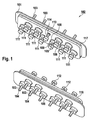
- Fig. 1
- zeigt eine räumliche Darstellung einer erfindungsgemäßen Durchführung mit zehn Anschlussstiften für Implantat-Signale mit einem elften Anschlussstift für die elektrische Masseanbindung.
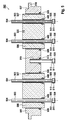
- Fig. 2
- zeigt eine Schnittdarstellung einer weiteren Ausführungsform der erfindungsgemäßen Durchführung.
- Fig. 3
- zeigt eine Schnittdarstellung einer Variante der erfindungsgemäßen Durchführung aus
Fig. 2 mit vier nagelkopfförmigen Anschlussstiften für ImplantatSignale und einem nagelkopfförmigen Massestift - Fig. 4
- zeigt eine Schnittdarstellung einer weiteren Variante der erfindungsgemäßen Durchführung mit fünf Anschlussstiften, die mit einer das Reflow-Weichlöten verbessernden Beschichtung (Vorverzinnung) versehen sind
- Fig. 5
- zeigt eine Schnittdarstellung der zusätzlichen Variante der erfindungsgemäßen Durchführung aus
Fig. 2 mit fünf Anschlussstiften, wobei eine Durchführungshülse mindestens zwei Anschlusselektroden führt und die Anschlussstifte mit einer die Weichlötbarkeit verbessernden Beschichtung versehen sind. - Fig. 6
- zeigt eine Schnittdarstellung einer alternativen Ausführungsform der erfindungsgemäßen Durchführung mit fünf Anschlusselektroden und mit Glas verlöteten Komponenten
- Fig. 7
- zeigt eine Schnittdarstellung einer weiteren Ausführungsform der erfindungsgemäßen Durchführung mit einem Filterkondensator
- Fig. 1
- shows a three-dimensional view of an implementation according to the invention with ten pins for implant signals with an eleventh pin for electrical ground connection.
- Fig. 2
- shows a sectional view of another embodiment of the implementation of the invention.
- Fig. 3
- shows a sectional view of a variant of the implementation of the invention
Fig. 2 with four nail-head pins for implant signals and a nail-headed ground pin - Fig. 4
- shows a sectional view of another variant of the implementation of the invention with five pins, which are provided with a reflow soldering coating (pre-tinning)
- Fig. 5
- shows a sectional view of the additional variant of the implementation of the invention
Fig. 2 with five pins, wherein a feedthrough sleeve leads at least two terminal electrodes and the pins are provided with a solderability improving coating. - Fig. 6
- shows a sectional view of an alternative embodiment of the implementation of the invention with five terminal electrodes and glass soldered components
- Fig. 7
- shows a sectional view of another embodiment of the implementation of the invention with a filter capacitor
Der Flansch 201 führt vorzugsweise mindestens eine zylindrische Durchführungshülse 206 aus biokompatiblem Al2O3 in seinen Flanschöffnungen 207. Jede der Hülsen ist mit einer Lotverbindung 208 aus biokompatiblem, metallischem Hartlot mit dem Flansch 201 verlötet. Die Durchführungshülsen 206 sind in dieser Ausführungsform im Bereich der Flanschöffnungen 207 mit einer metallischen Beschichtung versehen, vorzugsweise biokompatibel aus Nb, um diese für das Hartlot benetzungsfähig zu machen und dadurch eine Verlötung zu ermöglichen. In der hier gezeigten Variante überragen die keramischen Durchführungshülsen 206 den Flansch 201 beidseitig und sorgen für ausreichend lange elektrische Isolationsstrecken für Hochspannungsanwendungen der Durchführung 202.The
Der Anschlussstift 203 hat vorzugsweise eine einfache zylindrische Form, ein äußeres Ende 204 und ein inneres Ende 205, und ist mittels einer Lotverbindung 209 mit der Durchführungshülse 206 verbunden und damit zusammen mit der Durchführungshülse im Flansch 201 festgelegt. Sowohl die Lotverbindung 208 als auch 209 sind in der Produktionsphase als Lotringe ausgebildet, die sich zwischen dem Flansch 201 und den Durchführungshülsen 206 bzw. zwischen Durchführungshülsen 206 und Anschlussstiften 203 befinden. Durch Erhitzen, beispielsweise über elektrische Widerstandsbeheizung, elektrische Induktion, Wärmeleitung oder Infrarot-Einstrahlung, werden diese Ringe verflüssigt und bilden nach Erkalten eine biokompatible, mechanisch stabile, hermetisch dichte, Wechseltemperatur belastbare Lotverbindung.
Am inneren Ende 205 ist ein weichlötbarer Aufsatz 211, vorzugsweise in Form von Nickel-Scheiben über eine Fügestelle 212 angefügt. Um die genannten Lotverbindungen 208, 209 und Fügestellen 212 im selben Prozess kostengünstig herstellen zu können, bestehen die Materialien der Lotverbindungen und der Fügestelle vorzugsweise aus demselben Lotmaterial wie beispielsweise Goldlote, Gold-Niob-, Gold-Tantal, Gold-Titan, Gold-Zirkonium-Legierungen. Alternativ können z. B. auch Kupfer-, Silber-, Kupfer-Nickel-, Kupfer-Zink-, Kupfer-Zinn, Silber-Kupfer-, Silber-Kupfer-Zink-, Silber-Kupfer-Zink-Zinn-, Silber-Kupfer-Zinn-, Silber-Kupfer-Zink-Kadmium-, Kupfer-Phosphor-, Kupfer-Phosphor-Silber-, Kupfer-Gold-Legierungen oder zahlreiche weitere Legierungen eingesetzt werden, um Temperatur-Inhomogenitäten während des Hartlötprozesses auszugleichen. Diese Implantat-innenseitig liegenden Fügestellen müssen wie auch die Implantat-innenseitig liegenden Anschlussstifte nicht biokompatibel ausgeführt sein, da sie durch das hermetisch dichte Implantatgehäuse und die hermetisch dichte Durchführung zur Außenseite hin getrennt sind.
Als bevorzugte Materialkombination wird Niob für den Anschlussstift 203 bzw. 214, Nickel für den weichlötbaren Aufsatz 211 und Feingold für das Hartlot 212 bzw. 215 gewählt, da Feingold sowohl mit Niob als auch mit Nickel Lotverbindungen erzeugt, die in jedem Legierungsverhältnis miteinander mischbar und stets duktile Phasen bilden. Die resultierenden Hartlotverbindungen sind derart stabil, dass bei mechanischer Belastung in den meisten Fällen die Anschlussstifte 203 bzw. 214 reißen bzw. versagen und nicht die Hartlotverbindungen 212.
Alternativ ist es prozesstechnisch aber auch vorteilhaft, in einem ersten Verfahrensschritt die Fügestelle 212 zwischen Anschlussstift 203 und Aufsatz 211 mit einem höher schmelzenden Hartlot zu fügen oder ohne Zusatz direkt zu verschweißen, um diese anschließend in einem zweiten Hartlötprozess mit den anderen Komponenten der Durchführung 202 zu verlöten, so dass mögliche Probleme - beispielsweise bei komplexen und/oder großräumigeren Strukturen - mit unverwünschten Temperatur-Inhomogenitäten vermieden werden. Wesentlich ist, dass kein Weichlot mit Zinnanteil in der Fügestelle 212 eingesetzt wird, um mechanisch wenig belastbare Sprödphasen zwischen Gold und Zinn zu vermeiden.
Weiter umfasst die elektrische Durchführung gemäß der gezeigten Ausführungsform einen Massestift 214, für den sie soeben dargestellten Betrachtungen bezüglich der Lotverbindungen ebenfalls gelten.The connecting
At the
As a preferred combination of materials niobium for the
Alternatively, it is also technically advantageous in a first method step to add the joint 212 between the
Furthermore, the electrical feedthrough according to the embodiment shown comprises a
Die inneren Flächen der Aufsätze 211 des Anschlussstifte 203 und des Massestiftes 214 befinden sich vorzugsweise alle annähernd in einer gemeinsamen Ebene und ermöglichen damit eine erfolgreiche Reflow-Verlötung, können aber auch in gewollt unterschiedlichen Ebenen liegen, wenn es die Anpassung an das korrespondierende Substrat des Implantats erfordert.The inner surfaces of the
In der hier gezeigten Ausführung weist der Flansch 201 eine Nut 217 zur Aufnahme der Halbschalen eines nicht dargestellten Implantatgehäuses auf. Eine Lippe 218 dient gleichzeitig als Schweißschutz beim Laser-Einschweißen des Flansches 201 mit den Gehäusehalbschalen des Implantats.In the embodiment shown here, the
Die Weichlotoberfläche ist zusätzlich durch ein besonderes Verfahren - beispielsweise durch thermische Vorbehandlung oder durch Schleifen ― in eine gemeinsame Ebene gebracht. Mit den Schichten 430 aus Weichlot wird im Allgemeinen eine bessere gemeinsame Ebenheit erreicht als es mit den Aufsätzen 411 allein möglich ist, sodass mit der Schicht produktionsbedingte Unebenheiten der weichlötbaren Aufsätze 411 ausgeglichen werden. Weiterhin schafft die Beschichtung günstige Voraussetzungen für ein Reflow-Weichlötverfahren, da es nicht mehr notwendig ist, erst während des Reflow-Lötens eine möglichst vollständige Benetzung der Aufsätze 411 mit Weichlot zu erzielen, da die Oberflächen der Aufsätze 411 bereits nahezu vollständig mit Weichlot benetzt sind. Die Seitenflächen der scheibenförmigen Aufsätze 411 können ebenfalls durch die Weichlotschicht 430 benetzt sein. Selbst wenn die goldlothaltigen Fügestellen 412 unabsichtlich mit zinnhaltigem Weichlot mit benetzt werden und dabei in den Übergangszonen Au-Sn-Sprödphasen ausgebildet werden, stellen die Au-Sn-Sprödphasen in dieser Anordnung keinen Nachteil dar, da die Au-Sn-Sprödphasen mechanisch keine Funktion übernehmen, mechanisch nicht nennenswert belastet werden und mit dem Rest der Weichlotschicht 430 duktil zusammenhängend sind, so dass sich keine Bestandteile oder Partikel des Weichlotes 430 in der weiteren Anwendung der Durchführung ablösen. Die inneren Enden 405 des Anschlussstiftes 403 oder des Massestiftes 414 können auch, wie in
Verfahrenstechnisch vorteilhaft weisen sowohl die Durchführungshülsen 406 als auch die Innenwände der Öffnungen 407 des Flansches 401 korrespondierende Schrägen oder Stufen 428 und 429 auf. Damit wird eine verjüngte Hülsenaußenfläche 426 gebildet, die im Allgemeinen weiter aus dem Flansch 401 herausragt als ohne Verjüngung, um eine ausreichende Isolationsstrecke zu gewährleisten. Mit dieser Konfiguration kann die Keramik vor dem Erstellen der Lötverbindung 408 im inneren Hohlraum des Flansches zentriert und muss nicht durch zusätzliche Hilfsmittel in Position gehalten werden.
The soft solder surface is additionally brought into a common plane by a special process, for example by thermal pretreatment or by grinding. With the
In terms of process technology, both the
In dieser Variante besitzt der Flansch 501 eine Einpassung 537, welche zum Einschweißen in eine Öffnung des nicht dargestellten Implantatgehäuses dient. Ein Anschlag bzw. eine Lippe 518 dient gleichzeitig als Schweißschutz beim Laser-Einschweißen des Flansches 501 mit dem Gehäuse bzw. den Gehäusehalbschalen des Implantats.
In this variant, the
Eine besondere Ausführungsform ist in
Gegebenenfalls können in weiteren Varianten die Durchführungshülsen 606 und/oder 636 gleichzeitig weggelassen werden, wenn dafür geeignete Materialien bzw. Materialkombinationen für den Flansch, die Anschlussstifte und das Glaslot gewählt werden. In solchen Fällen ist Beispielsweise das Glaslot von seiner Zusammensetzung her weniger oxidierend oder sogar reduzierend eingestellt, so dass die Metalloberflächen für das Glaslot weniger attraktiv wirken, die Oberflächenspannung des Glaslotes in der Hartverlötung dominiert und letztendlich das Glas trotz niedriger Viskosität während der Verarbeitung nicht aus den Öffnungen 607 heraus fließt. Diese Varianten haben den Vorteil, dass die Verlötungen insgesamt Raum sparender als mit gleichzeitig zwei Durchführungshülsen ausgeführt werden können. Die Öffnungen 607 können in weiteren Varianten Schrägen oder Stufen wie in
Optionally, in further variants, the
Zur elektromagnetischen Filterung wird in dieser Variante ein Filterkondensator 757 eingesetzt, der mittels einer Hülse 753 am Flansch gehalten wird. Die Hülse 753 ist mittels einem oder mehrerer Schweißpunkte oder -Nähte 751 am Flansch 701 elektrisch und mechanisch angefügt, wobei der Flansch 701 zur besseren Positionierung der Hülse 753 bezüglich des Flansches 701 eine Vertiefung aufweisen kann. Die Schweißpunkte 751 sind dabei so angelegt, dass zwischen der Hülse 753 und dem Flansch 701 eine Lecktestverbindung geschaffen wird.
Der Filterkondensator 757 umfasst plattenförmige Elektroden 756 und 758, die in einem Dielektrikum 757, welches beispielsweise aus Bariumtitanat besteht, eingebettet sind. Die Elektroden 756 weisen an der Außenseite des Kondensators eine weichlötbare Metallisierung 755 aus beispielsweise Palladium, Silber, Kupfer oder deren Legierungen auf. An dieser Metallisierung erfolgt eine elektrische und mechanische Masseverbindung über eine feste Lötverbindung 754 mit der am Flansch 701 befestigten Hülse 753. Die Elektroden 758 sind ebenfalls mit einer weichlötbaren Metallisierung 765 ebenfalls aus Palladium, Silber, Kupfer oder deren Legierungen an den Öffnungen des Kondensators versehen, durch die sich die weichlötbaren Stifte 711 erstrecken und mittels der Lötverbindung 764 mit den weichlötbaren Stiften 711 verlötet sind, um die elektrischen Verbindungen zu den elektrischen Signalen des elektrischen Implantats zu bilden. Die Lötverbindungen 764 und 754 können aus Gründen der besseren Fertigung aus verschiedenartigen Weichloten mit unterschiedlichen Schmelzpunkten bzw. -bereichen bestehen. Dabei wird für als Material für die Lötverbindung 754 vorzugsweise eine Materialzusammensetzung gewählt, beispielsweise PbSn3,5Ag1,5, die mit einem Lötbereich von 305 °C eine höhere Verarbeitungstemperatur besitzt als das Material der Lötverbindung 764 mit der bevorzugten Materialzusammensetzung von beispielsweise PbSn5Ag2,5 und einer Löttemperatur von 280 °C. Somit kann in einem bevorzugten Herstellungsverfahren der Kondensator 757 zunächst an die weichlötbare Hülse 753 mit dem höher schmelzenden Weichlot 754 angelötet werden, die Hülse 753 mit dem angelöteten Kondensator 757 über die Stifte 711 gesteckt und an den Flansch 701 mittels Verschweißungen 750 elektrisch und mechanisch angefügt werden und schließlich mittels eines niedriger schmelzenden Weichlotes 764 an die weichlötbaren Stifte 711 angelötet werden, ohne dass dabei das höher schmelzende Weichlot 754 Gefahr läuft, während des zweiten Weichlötens mit dem Weichlot 764 erneut aufzuschmelzen und die Metallisierung 755 aufzulösen und dabei die elektrisch/mechanische Verbindung zu den Kondensatorelektroden 756 zu verlieren. Die so hergestellte elektrische Durchführung kann mittels eines Helium-Lecktests auf Hermetizität zwischen der Innen-und Außenseite des Implantats geprüft werden, da die Lecktestverbindung einen Durchgang zum von Flansch 701, Hülse 753, Kondensator 757 und den einzelnen inneren Durchführungshülsen 706 und weichlötbaren Stiften 711 begrenzen Hohlraum 752 schafft, durch den das Helium strömen kann.
In weiteren Varianten dieser Ausführungsform können anstatt eines einzelnen Kondensators 757 auch mehrere unabhängige Kondensatoren verwendet werden. Es ist auch möglich, nur einzelne Anschlussstifte mittels Kondensatoren 757 zu filtern (beispielsweise für eine Antennenanbindung zur drahtlosen Übertragung von Signalen aus dem Implantat heraus). Die elektrische und mechanische Anbindung des Kondensators 757 kann auch mittels elektrisch leitfähigen Klebern, mittels Schweißen, Klemmen oder Stecken realisiert sein, wobei stets auf die Lecktestbarkeit der Anordnung ein besonderer Wert gelegt wird. Die Lecktestbarkeit kann alternativ oder zusätzlich durch nicht dargestellte, zusätzliche Öffnungen im Kondensator 757, in den Loten 754 und 764 und/oder in der Hülse 753 realisiert sein. Der Flansch 701 kann alternativ so geformt sein, dass sich anstatt der Hülse 753 der Flansch an ähnlicher Stelle fortsetzt und den Kondensator 757 aufnimmt und zur Lecktestbarkeit eine zusätzliche Öffnung in der so entstandenen, hier nicht dargestellten Wandung zum Hohlraum 752 besitzt.
For electromagnetic filtering, a
The
In other variants of this embodiment, instead of a
In allen genannten Ausführungsformen können auch andere als die genannten Fügetechniken und Ausformungen angewendet werden, wie beispielsweise durch Schweißen, Klemmen, elektrisch leitfähiges Kleben, Bonden und dergleichen.
In weiteren Varianten können die Stifte 711 auch mit den in den
In weiteren sinnvollen Varianten können sämtliche Kombinationen und geometrische Modifikationen aus den
In other variants, the
In other meaningful variants, all combinations and geometric modifications of the
- 101, 201, 301, 401, 501, 601, 701101, 201, 301, 401, 501, 601, 701
- Flanschflange
- 102, 202, 302, 402, 502, 602, 702102, 202, 302, 402, 502, 602, 702
- Durchführungexecution
- 103, 203, 303, 403, 503, 603, 703103, 203, 303, 403, 503, 603, 703
- Anschlussstiftpin
- 104, 204, 304, 404, 504, 604, 704104, 204, 304, 404, 504, 604, 704
- äußeres, biokompatibles Ende des Anschlussstiftsouter, biocompatible end of the connector pin
- 105, 205, 305, 405, 505, 605, 705105, 205, 305, 405, 505, 605, 705
- inneres Ende der Anschlussstiftsinner end of the connector pin
- 106, 206, 306, 406, 506, 606, 706106, 206, 306, 406, 506, 606, 706
- Durchführungshülse, innere DurchführungshülseBushing, inner bushing
- 207, 307, 407, 507, 607, 707207, 307, 407, 507, 607, 707
- Öffnung im FlanschOpening in the flange
- 108, 208, 308, 408, 508, 607, 708108, 208, 308, 408, 508, 607, 708
- Lotverbindung zwischen Flansch und DurchführungshülseSolder connection between flange and grommet
- 109, 209, 309, 409, 509, 609, 709109, 209, 309, 409, 509, 609, 709
- Lotverbindung zwischen Anschlusselektrode und DurchführungshülseSolder connection between connection electrode and feedthrough sleeve
- 310, 410310, 410
- Nagelkopfartiger Ansatz am inneren Ende des AnschlussstiftesNail-like attachment at the inner end of the terminal pin
- 111, 211, 311, 411, 511, 611, 711 1111, 211, 311, 411, 511, 611, 711 1
- weichlötbarer Aufsatz des Anschlussstiftessolderable attachment of the connecting pin
- 112, 212, 312, 412, 512, 612, 712112, 212, 312, 412, 512, 612, 712
- Fügestelle zwischen Anschlussstift und AufsatzJoint between pin and attachment
- 113, 213, 313, 413, 513, 613 3113, 213, 313, 413, 513, 613 3
- Lotverbindung zwischen Massestift und FlanschSolder connection between ground pin and flange
- 114,214,314,414,514,614,714114,214,314,414,514,614,714
- Masse-Anschlussstift oder Massestift oder MassepinGround pin or ground pin or ground pin
- 117, 217, 317, 417, 517, 617, 717117, 217, 317, 417, 517, 617, 717
- Nut im Flansch zur Aufnahme der ImplantatGehäusehälftenGroove in the flange for receiving the implant housing halves
- 118, 218, 318, 418, 518, 618, 718118, 218, 318, 418, 518, 618, 718
- Innenseite LippeInside lip
- 219, 319, 419, 519, 619219, 319, 419, 519, 619
- Öffnung zur Aufnahme des MassestiftesOpening for receiving the mass pin
- 428428
- Abstufung im FlanschGradation in the flange
- 429429
- Abstufung in der DurchführungshülseGradation in the bushing
- 430, 530, 630, 730430, 530, 630, 730
- Weichlot (am Ende planiert) oder weichlötbare Beschichtung Schicht am weichlötbaren AufsatzSoft solder (leveled at the end) or soft solderable coating Layer on the solderable attachment
- 535535
-
"Slot" bzw. Vertiefung in der Durchführungshülse 506 zur Vergrößerung der Isolationsstrecke z. B. zwischen zwei Stiften 503 oder zwischen einem Stift 503 und dem Flansch 501 1"Slot" or recess in the
bushing 506 to increase the isolation distance z. B. between twopins 503 or between apin 503 and theflange 501 first - 636, 736636, 736
- Äußere DurchführungshülseOuter bushing
- 537537
- Schweißeinpassung im FlanschWeld fitting in the flange
- 751 1751 1
- Schweißpunkte bzw. -nähte 750Welding points or seams 750
- 752752
- Hohlraumcavity
- 753753
- weichlötbare und schweißbare metallische Hülsesoft solderable and weldable metallic sleeve
- 754754
-
Lötverbindung zwischen Hülse 753 und Metallisierung 755 des Kondensators 757Solder connection between
sleeve 753 andmetallization 755 of thecapacitor 757 - 755, 765755, 765
-
Metallisierung des Kondensators 757Metallization of the
capacitor 757 - 756, 758756, 758
- Kondensatorelektrodecapacitor electrode
- 757757
- Keramik-DielektrikumCeramic dielectric
- 764764
-
Lötverbindung zwischen weichlötbarem Stift 711 und Metallisierung 765 des Kondensators 757Solder connection between soft-
solderable pin 711 andmetallization 765 of thecapacitor 757
Claims (14)
Applications Claiming Priority (1)
| Application Number | Priority Date | Filing Date | Title |
|---|---|---|---|
| US31840510P | 2010-03-29 | 2010-03-29 |
Publications (3)
| Publication Number | Publication Date |
|---|---|
| EP2371418A2 true EP2371418A2 (en) | 2011-10-05 |
| EP2371418A3 EP2371418A3 (en) | 2014-09-24 |
| EP2371418B1 EP2371418B1 (en) | 2021-11-03 |
Family
ID=44287327
Family Applications (1)
| Application Number | Title | Priority Date | Filing Date |
|---|---|---|---|
| EP11156793.9A Active EP2371418B1 (en) | 2010-03-29 | 2011-03-03 | Electrical feedthrough for electromedical implants |
Country Status (2)
| Country | Link |
|---|---|
| US (1) | US8536468B2 (en) |
| EP (1) | EP2371418B1 (en) |
Cited By (7)
| Publication number | Priority date | Publication date | Assignee | Title |
|---|---|---|---|---|
| EP2965783A1 (en) | 2014-07-07 | 2016-01-13 | BIOTRONIK SE & Co. KG | Method for producing a pin for a feedthrough of an electromedical implant and a feedthrough |
| EP3181194A1 (en) | 2015-12-15 | 2017-06-21 | BIOTRONIK SE & Co. KG | Feedthrough of a medical electronic device, method for producing same, and medical electronic device |
| EP3332836A1 (en) | 2016-12-09 | 2018-06-13 | BIOTRONIK SE & Co. KG | Performing an implantable medical electronic device |
| EP3384958A1 (en) * | 2017-04-03 | 2018-10-10 | BIOTRONIK SE & Co. KG | Feedthrough for implant components |
| EP3461533A1 (en) | 2017-09-29 | 2019-04-03 | BIOTRONIK SE & Co. KG | External casing part of an implantable medical electronic device |
| EP3939730A1 (en) | 2020-07-14 | 2022-01-19 | BIOTRONIK SE & Co. KG | Method of joining a first and a second components of a lead-through using a reactive multilayer system |
| US11806542B2 (en) | 2020-02-11 | 2023-11-07 | Inspire Medical Systems, Inc. | Feedthrough mounting for an electronic device, such as an implantable medical device, and methods of making the same |
Families Citing this family (26)
| Publication number | Priority date | Publication date | Assignee | Title |
|---|---|---|---|---|
| DE102009035971B4 (en) * | 2009-08-04 | 2013-01-17 | Heraeus Precious Metals Gmbh & Co. Kg | Electrical leadthrough for a medically implantable device |
| DE102009035972B4 (en) | 2009-08-04 | 2011-11-17 | W.C. Heraeus Gmbh | Cermet-containing lead-through for a medically implantable device |
| DE102010006689B4 (en) | 2010-02-02 | 2013-04-18 | Heraeus Precious Metals Gmbh & Co. Kg | Method for producing an electrical feedthrough, electrical feedthrough and implantable device |
| DE102010006690B4 (en) * | 2010-02-02 | 2013-03-28 | Heraeus Precious Metals Gmbh & Co. Kg | Method for producing an electrical feedthrough, electrical feedthrough and implantable device |
| US20130058004A1 (en) * | 2011-09-01 | 2013-03-07 | Medtronic, Inc. | Feedthrough assembly including underfill access channel and electrically insulating material |
| US9889306B2 (en) | 2012-01-16 | 2018-02-13 | Greatbatch Ltd. | Hermetically sealed feedthrough with co-fired filled via and conductive insert for an active implantable medical device |
| EP2636427B1 (en) * | 2012-01-16 | 2019-02-27 | Greatbatch Ltd. | Elevated hermetic feedthrough insulator adapted for side attachment of electrical conductors on the body fluid side of an active implantable medical device |
| US10881867B2 (en) | 2012-01-16 | 2021-01-05 | Greatbatch Ltd. | Method for providing a hermetically sealed feedthrough with co-fired filled via for an active implantable medical device |
| US20150250386A1 (en) * | 2012-09-28 | 2015-09-10 | Csem Centre Suisse D'electronique Et De Microtechnique Sa -Recherche Et Developpement | Implantable devices |
| US9478959B2 (en) | 2013-03-14 | 2016-10-25 | Heraeus Deutschland GmbH & Co. KG | Laser welding a feedthrough |
| US9431801B2 (en) | 2013-05-24 | 2016-08-30 | Heraeus Deutschland GmbH & Co. KG | Method of coupling a feedthrough assembly for an implantable medical device |
| US9403023B2 (en) | 2013-08-07 | 2016-08-02 | Heraeus Deutschland GmbH & Co. KG | Method of forming feedthrough with integrated brazeless ferrule |
| US9610452B2 (en) | 2013-12-12 | 2017-04-04 | Heraeus Deutschland GmbH & Co. KG | Direct integration of feedthrough to implantable medical device housing by sintering |
| US9504841B2 (en) | 2013-12-12 | 2016-11-29 | Heraeus Deutschland GmbH & Co. KG | Direct integration of feedthrough to implantable medical device housing with ultrasonic welding |
| US9610451B2 (en) | 2013-12-12 | 2017-04-04 | Heraeus Deutschland GmbH & Co. KG | Direct integration of feedthrough to implantable medical device housing using a gold alloy |
| DE102014216765A1 (en) * | 2014-08-22 | 2016-02-25 | Zf Friedrichshafen Ag | Media-tight housing |
| US9735477B2 (en) | 2014-10-14 | 2017-08-15 | Biotronik Se & Co. Kg | Terminal pin, feedthrough of an implantable electromedical device and process for making the same |
| DE102015208877B4 (en) | 2014-11-19 | 2024-02-29 | Vitesco Technologies Germany Gmbh | Electronic component |
| EP3069760B1 (en) | 2015-03-20 | 2020-04-29 | BIOTRONIK SE & Co. KG | Implantable electromedical device |
| US9985372B2 (en) * | 2015-03-20 | 2018-05-29 | BIOTRONIK SE Co. KG | Terminal pin and feedthrough |
| KR101656723B1 (en) * | 2015-06-30 | 2016-09-12 | 재단법인 오송첨단의료산업진흥재단 | Feedthrough making method |
| US10741223B2 (en) * | 2016-06-06 | 2020-08-11 | Western Digital Technologies, Inc. | Sealed bulkhead electrical feed-through positioning control |
| JP2018005960A (en) * | 2016-07-01 | 2018-01-11 | エヌイーシー ショット コンポーネンツ株式会社 | Airtight terminal having contactor |
| EP3311883B1 (en) * | 2016-10-21 | 2020-01-29 | BIOTRONIK SE & Co. KG | Terminal pin and feedthrough |
| EP4226968A1 (en) | 2020-02-21 | 2023-08-16 | Heraeus Medical Components, LLC | Ferrule for non-planar medical device housing |
| EP3900782B1 (en) | 2020-02-21 | 2023-08-09 | Heraeus Medical Components, LLC | Ferrule with strain relief spacer for implantable medical device |
Citations (1)
| Publication number | Priority date | Publication date | Assignee | Title |
|---|---|---|---|---|
| US5870272A (en) | 1997-05-06 | 1999-02-09 | Medtronic Inc. | Capacitive filter feedthrough for implantable medical device |
Family Cites Families (11)
| Publication number | Priority date | Publication date | Assignee | Title |
|---|---|---|---|---|
| US5751539A (en) * | 1996-04-30 | 1998-05-12 | Maxwell Laboratories, Inc. | EMI filter for human implantable heart defibrillators and pacemakers |
| US5905627A (en) * | 1997-09-10 | 1999-05-18 | Maxwell Energy Products, Inc. | Internally grounded feedthrough filter capacitor |
| US6414835B1 (en) * | 2000-03-01 | 2002-07-02 | Medtronic, Inc. | Capacitive filtered feedthrough array for an implantable medical device |
| US6529103B1 (en) * | 2000-09-07 | 2003-03-04 | Greatbatch-Sierra, Inc. | Internally grounded feedthrough filter capacitor with improved ground plane design for human implant and other applications |
| EP1488434B1 (en) * | 2002-02-28 | 2012-12-12 | Greatbatch Ltd. | Emi feedthrough filter terminal assembly utilizing hermetic seal for electrical attachment between lead wires and capacitor |
| US7038900B2 (en) * | 2003-02-27 | 2006-05-02 | Greatbatch-Sierra, Inc. | EMI filter terminal assembly with wire bond pads for human implant applications |
| US6768629B1 (en) * | 2003-06-02 | 2004-07-27 | Greatbatch-Hittman, Inc. | Multipin feedthrough containing a ground pin passing through an insulator and directly brazed to a ferrule |
| US6903268B2 (en) * | 2003-10-29 | 2005-06-07 | Medtronic, Inc. | Implantable device feedthrough assembly |
| US7035077B2 (en) * | 2004-05-10 | 2006-04-25 | Greatbatch-Sierra, Inc. | Device to protect an active implantable medical device feedthrough capacitor from stray laser weld strikes, and related manufacturing process |
| JP2009514617A (en) * | 2005-11-11 | 2009-04-09 | グレートバッチ リミテッド | Tank filter placed in series with active medical device lead wires or circuitry to enhance MRI compatibility |
| US8326425B2 (en) * | 2006-03-30 | 2012-12-04 | Cardiac Pacemakers, Inc. | Feedthrough connector for implantable device |
-
2011
- 2011-03-03 EP EP11156793.9A patent/EP2371418B1/en active Active
- 2011-03-09 US US13/043,886 patent/US8536468B2/en active Active
Patent Citations (1)
| Publication number | Priority date | Publication date | Assignee | Title |
|---|---|---|---|---|
| US5870272A (en) | 1997-05-06 | 1999-02-09 | Medtronic Inc. | Capacitive filter feedthrough for implantable medical device |
Cited By (12)
| Publication number | Priority date | Publication date | Assignee | Title |
|---|---|---|---|---|
| EP2965783A1 (en) | 2014-07-07 | 2016-01-13 | BIOTRONIK SE & Co. KG | Method for producing a pin for a feedthrough of an electromedical implant and a feedthrough |
| US9821395B2 (en) | 2014-07-07 | 2017-11-21 | Biotronik Se & Co. Kg | Method for producing a pin for a feedthrough of an electromedical implant and a feedthrough |
| EP3181194A1 (en) | 2015-12-15 | 2017-06-21 | BIOTRONIK SE & Co. KG | Feedthrough of a medical electronic device, method for producing same, and medical electronic device |
| DE102015121818A1 (en) | 2015-12-15 | 2017-06-22 | Biotronik Se & Co. Kg | Implementation of a medical electronic device, method for producing such and medical electronic device |
| EP3332836A1 (en) | 2016-12-09 | 2018-06-13 | BIOTRONIK SE & Co. KG | Performing an implantable medical electronic device |
| US10857367B2 (en) | 2016-12-09 | 2020-12-08 | Biotronik Se & Co. Kg | Feedthrough of an implantable medical electronic device |
| EP3384958A1 (en) * | 2017-04-03 | 2018-10-10 | BIOTRONIK SE & Co. KG | Feedthrough for implant components |
| EP3461533A1 (en) | 2017-09-29 | 2019-04-03 | BIOTRONIK SE & Co. KG | External casing part of an implantable medical electronic device |
| EP3461534A1 (en) * | 2017-09-29 | 2019-04-03 | BIOTRONIK SE & Co. KG | External casing part of an implantable medical electronic device |
| US11129995B2 (en) | 2017-09-29 | 2021-09-28 | Biotronik Se & Co. Kg | Outer casing part of an implantable medical electronic device |
| US11806542B2 (en) | 2020-02-11 | 2023-11-07 | Inspire Medical Systems, Inc. | Feedthrough mounting for an electronic device, such as an implantable medical device, and methods of making the same |
| EP3939730A1 (en) | 2020-07-14 | 2022-01-19 | BIOTRONIK SE & Co. KG | Method of joining a first and a second components of a lead-through using a reactive multilayer system |
Also Published As
| Publication number | Publication date |
|---|---|
| EP2371418B1 (en) | 2021-11-03 |
| US20110232961A1 (en) | 2011-09-29 |
| EP2371418A3 (en) | 2014-09-24 |
| US8536468B2 (en) | 2013-09-17 |
Similar Documents
| Publication | Publication Date | Title |
|---|---|---|
| EP2371418B1 (en) | Electrical feedthrough for electromedical implants | |
| US10589107B2 (en) | Circuit board mounted filtered feedthrough assembly having a composite conductive lead for an AIMD | |
| DE19819797C2 (en) | Feedthrough assembly for an implantable medical device | |
| EP1897588B1 (en) | Feedthrough connection | |
| EP2371417B1 (en) | Electrical feedthrough, method for the production and use thereof | |
| DE102011009866B4 (en) | Directly applied electrical feedthrough | |
| DE10059373B4 (en) | Leak test, capacitively filtered feedthrough for an implantable medical device | |
| EP1897589A2 (en) | Electric duct | |
| EP1923099A1 (en) | Filter duct for implants | |
| WO2014160193A2 (en) | Laser welding a feedthrough | |
| EP2926864A1 (en) | Electric feedthrough for electromedical implants, electric contact element comprising such a feedthrough, and electromedical implant | |
| US11202916B2 (en) | Hermetic terminal for an AIMD having a pin joint in a feedthrough capacitor or circuit board | |
| EP2371419A2 (en) | Electrical feedthrough of a capacitor for medical implants and method for the production and use thereof | |
| EP3072553B1 (en) | Terminal pin and feedthrough | |
| EP3069757A1 (en) | Feedthrough of an implantable electronic medical device and implantable electronic medical device | |
| EP3181194A1 (en) | Feedthrough of a medical electronic device, method for producing same, and medical electronic device | |
| EP3332836B1 (en) | Feedthrough of an implantable medical electronic device | |
| EP3069760B1 (en) | Implantable electromedical device | |
| EP3200568B1 (en) | Battery bridge and method for activating an electronic device | |
| EP3311883A1 (en) | Anschlussstift und durchführung | |
| EP3069756A1 (en) | Feedthrough of an implantable medical electronic device, method for producing same, and implantable medical electronic device | |
| EP3939730A1 (en) | Method of joining a first and a second components of a lead-through using a reactive multilayer system | |
| EP3069759A1 (en) | Implantable electromedical device with a feedthrough having a single piece polymeric base body | |
| DE102016107414A1 (en) | Implementation of an implantable medical electronic device and implantable medical electronic device | |
| DE19526169A1 (en) | Overload protection / switching PTC thermistor and method for its production |
Legal Events
| Date | Code | Title | Description |
|---|---|---|---|
| PUAI | Public reference made under article 153(3) epc to a published international application that has entered the european phase |
Free format text: ORIGINAL CODE: 0009012 |
|
| AK | Designated contracting states |
Kind code of ref document: A2 Designated state(s): AL AT BE BG CH CY CZ DE DK EE ES FI FR GB GR HR HU IE IS IT LI LT LU LV MC MK MT NL NO PL PT RO RS SE SI SK SM TR |
|
| AX | Request for extension of the european patent |
Extension state: BA ME |
|
| PUAL | Search report despatched |
Free format text: ORIGINAL CODE: 0009013 |
|
| AK | Designated contracting states |
Kind code of ref document: A3 Designated state(s): AL AT BE BG CH CY CZ DE DK EE ES FI FR GB GR HR HU IE IS IT LI LT LU LV MC MK MT NL NO PL PT RO RS SE SI SK SM TR |
|
| AX | Request for extension of the european patent |
Extension state: BA ME |
|
| RIC1 | Information provided on ipc code assigned before grant |
Ipc: A61N 1/375 20060101AFI20140818BHEP |
|
| 17P | Request for examination filed |
Effective date: 20150223 |
|
| RBV | Designated contracting states (corrected) |
Designated state(s): AL AT BE BG CH CY CZ DE DK EE ES FI FR GB GR HR HU IE IS IT LI LT LU LV MC MK MT NL NO PL PT RO RS SE SI SK SM TR |
|
| STAA | Information on the status of an ep patent application or granted ep patent |
Free format text: STATUS: EXAMINATION IS IN PROGRESS |
|
| 17Q | First examination report despatched |
Effective date: 20180417 |
|
| STAA | Information on the status of an ep patent application or granted ep patent |
Free format text: STATUS: EXAMINATION IS IN PROGRESS |
|
| GRAP | Despatch of communication of intention to grant a patent |
Free format text: ORIGINAL CODE: EPIDOSNIGR1 |
|
| STAA | Information on the status of an ep patent application or granted ep patent |
Free format text: STATUS: GRANT OF PATENT IS INTENDED |
|
| INTG | Intention to grant announced |
Effective date: 20210527 |
|
| GRAS | Grant fee paid |
Free format text: ORIGINAL CODE: EPIDOSNIGR3 |
|
| GRAA | (expected) grant |
Free format text: ORIGINAL CODE: 0009210 |
|
| STAA | Information on the status of an ep patent application or granted ep patent |
Free format text: STATUS: THE PATENT HAS BEEN GRANTED |
|
| AK | Designated contracting states |
Kind code of ref document: B1 Designated state(s): AL AT BE BG CH CY CZ DE DK EE ES FI FR GB GR HR HU IE IS IT LI LT LU LV MC MK MT NL NO PL PT RO RS SE SI SK SM TR |
|
| REG | Reference to a national code |
Ref country code: GB Ref legal event code: FG4D Free format text: NOT ENGLISH |
|
| REG | Reference to a national code |
Ref country code: AT Ref legal event code: REF Ref document number: 1443429 Country of ref document: AT Kind code of ref document: T Effective date: 20211115 Ref country code: CH Ref legal event code: EP |
|
| REG | Reference to a national code |
Ref country code: IE Ref legal event code: FG4D Free format text: LANGUAGE OF EP DOCUMENT: GERMAN |
|
| REG | Reference to a national code |
Ref country code: DE Ref legal event code: R096 Ref document number: 502011017257 Country of ref document: DE |
|
| REG | Reference to a national code |
Ref country code: LT Ref legal event code: MG9D |
|
| REG | Reference to a national code |
Ref country code: NL Ref legal event code: MP Effective date: 20211103 |
|
| PG25 | Lapsed in a contracting state [announced via postgrant information from national office to epo] |
Ref country code: RS Free format text: LAPSE BECAUSE OF FAILURE TO SUBMIT A TRANSLATION OF THE DESCRIPTION OR TO PAY THE FEE WITHIN THE PRESCRIBED TIME-LIMIT Effective date: 20211103 Ref country code: LT Free format text: LAPSE BECAUSE OF FAILURE TO SUBMIT A TRANSLATION OF THE DESCRIPTION OR TO PAY THE FEE WITHIN THE PRESCRIBED TIME-LIMIT Effective date: 20211103 Ref country code: FI Free format text: LAPSE BECAUSE OF FAILURE TO SUBMIT A TRANSLATION OF THE DESCRIPTION OR TO PAY THE FEE WITHIN THE PRESCRIBED TIME-LIMIT Effective date: 20211103 Ref country code: BG Free format text: LAPSE BECAUSE OF FAILURE TO SUBMIT A TRANSLATION OF THE DESCRIPTION OR TO PAY THE FEE WITHIN THE PRESCRIBED TIME-LIMIT Effective date: 20220203 |
|
| PG25 | Lapsed in a contracting state [announced via postgrant information from national office to epo] |
Ref country code: IS Free format text: LAPSE BECAUSE OF FAILURE TO SUBMIT A TRANSLATION OF THE DESCRIPTION OR TO PAY THE FEE WITHIN THE PRESCRIBED TIME-LIMIT Effective date: 20220303 Ref country code: SE Free format text: LAPSE BECAUSE OF FAILURE TO SUBMIT A TRANSLATION OF THE DESCRIPTION OR TO PAY THE FEE WITHIN THE PRESCRIBED TIME-LIMIT Effective date: 20211103 Ref country code: PT Free format text: LAPSE BECAUSE OF FAILURE TO SUBMIT A TRANSLATION OF THE DESCRIPTION OR TO PAY THE FEE WITHIN THE PRESCRIBED TIME-LIMIT Effective date: 20220303 Ref country code: PL Free format text: LAPSE BECAUSE OF FAILURE TO SUBMIT A TRANSLATION OF THE DESCRIPTION OR TO PAY THE FEE WITHIN THE PRESCRIBED TIME-LIMIT Effective date: 20211103 Ref country code: NO Free format text: LAPSE BECAUSE OF FAILURE TO SUBMIT A TRANSLATION OF THE DESCRIPTION OR TO PAY THE FEE WITHIN THE PRESCRIBED TIME-LIMIT Effective date: 20220203 Ref country code: NL Free format text: LAPSE BECAUSE OF FAILURE TO SUBMIT A TRANSLATION OF THE DESCRIPTION OR TO PAY THE FEE WITHIN THE PRESCRIBED TIME-LIMIT Effective date: 20211103 Ref country code: LV Free format text: LAPSE BECAUSE OF FAILURE TO SUBMIT A TRANSLATION OF THE DESCRIPTION OR TO PAY THE FEE WITHIN THE PRESCRIBED TIME-LIMIT Effective date: 20211103 Ref country code: HR Free format text: LAPSE BECAUSE OF FAILURE TO SUBMIT A TRANSLATION OF THE DESCRIPTION OR TO PAY THE FEE WITHIN THE PRESCRIBED TIME-LIMIT Effective date: 20211103 Ref country code: GR Free format text: LAPSE BECAUSE OF FAILURE TO SUBMIT A TRANSLATION OF THE DESCRIPTION OR TO PAY THE FEE WITHIN THE PRESCRIBED TIME-LIMIT Effective date: 20220204 Ref country code: ES Free format text: LAPSE BECAUSE OF FAILURE TO SUBMIT A TRANSLATION OF THE DESCRIPTION OR TO PAY THE FEE WITHIN THE PRESCRIBED TIME-LIMIT Effective date: 20211103 |
|
| PG25 | Lapsed in a contracting state [announced via postgrant information from national office to epo] |
Ref country code: SM Free format text: LAPSE BECAUSE OF FAILURE TO SUBMIT A TRANSLATION OF THE DESCRIPTION OR TO PAY THE FEE WITHIN THE PRESCRIBED TIME-LIMIT Effective date: 20211103 Ref country code: SK Free format text: LAPSE BECAUSE OF FAILURE TO SUBMIT A TRANSLATION OF THE DESCRIPTION OR TO PAY THE FEE WITHIN THE PRESCRIBED TIME-LIMIT Effective date: 20211103 Ref country code: RO Free format text: LAPSE BECAUSE OF FAILURE TO SUBMIT A TRANSLATION OF THE DESCRIPTION OR TO PAY THE FEE WITHIN THE PRESCRIBED TIME-LIMIT Effective date: 20211103 Ref country code: EE Free format text: LAPSE BECAUSE OF FAILURE TO SUBMIT A TRANSLATION OF THE DESCRIPTION OR TO PAY THE FEE WITHIN THE PRESCRIBED TIME-LIMIT Effective date: 20211103 Ref country code: DK Free format text: LAPSE BECAUSE OF FAILURE TO SUBMIT A TRANSLATION OF THE DESCRIPTION OR TO PAY THE FEE WITHIN THE PRESCRIBED TIME-LIMIT Effective date: 20211103 Ref country code: CZ Free format text: LAPSE BECAUSE OF FAILURE TO SUBMIT A TRANSLATION OF THE DESCRIPTION OR TO PAY THE FEE WITHIN THE PRESCRIBED TIME-LIMIT Effective date: 20211103 |
|
| REG | Reference to a national code |
Ref country code: DE Ref legal event code: R097 Ref document number: 502011017257 Country of ref document: DE |
|
| PLBE | No opposition filed within time limit |
Free format text: ORIGINAL CODE: 0009261 |
|
| STAA | Information on the status of an ep patent application or granted ep patent |
Free format text: STATUS: NO OPPOSITION FILED WITHIN TIME LIMIT |
|
| 26N | No opposition filed |
Effective date: 20220804 |
|
| PG25 | Lapsed in a contracting state [announced via postgrant information from national office to epo] |
Ref country code: MC Free format text: LAPSE BECAUSE OF FAILURE TO SUBMIT A TRANSLATION OF THE DESCRIPTION OR TO PAY THE FEE WITHIN THE PRESCRIBED TIME-LIMIT Effective date: 20211103 Ref country code: AL Free format text: LAPSE BECAUSE OF FAILURE TO SUBMIT A TRANSLATION OF THE DESCRIPTION OR TO PAY THE FEE WITHIN THE PRESCRIBED TIME-LIMIT Effective date: 20211103 |
|
| GBPC | Gb: european patent ceased through non-payment of renewal fee |
Effective date: 20220303 |
|
| PG25 | Lapsed in a contracting state [announced via postgrant information from national office to epo] |
Ref country code: SI Free format text: LAPSE BECAUSE OF FAILURE TO SUBMIT A TRANSLATION OF THE DESCRIPTION OR TO PAY THE FEE WITHIN THE PRESCRIBED TIME-LIMIT Effective date: 20211103 |
|
| REG | Reference to a national code |
Ref country code: BE Ref legal event code: MM Effective date: 20220331 |
|
| PG25 | Lapsed in a contracting state [announced via postgrant information from national office to epo] |
Ref country code: LU Free format text: LAPSE BECAUSE OF NON-PAYMENT OF DUE FEES Effective date: 20220303 Ref country code: GB Free format text: LAPSE BECAUSE OF NON-PAYMENT OF DUE FEES Effective date: 20220303 Ref country code: FR Free format text: LAPSE BECAUSE OF NON-PAYMENT OF DUE FEES Effective date: 20220331 |
|
| PG25 | Lapsed in a contracting state [announced via postgrant information from national office to epo] |
Ref country code: BE Free format text: LAPSE BECAUSE OF NON-PAYMENT OF DUE FEES Effective date: 20220331 |
|
| PGFP | Annual fee paid to national office [announced via postgrant information from national office to epo] |
Ref country code: IE Payment date: 20230320 Year of fee payment: 13 |
|
| REG | Reference to a national code |
Ref country code: AT Ref legal event code: MM01 Ref document number: 1443429 Country of ref document: AT Kind code of ref document: T Effective date: 20220303 |
|
| PG25 | Lapsed in a contracting state [announced via postgrant information from national office to epo] |
Ref country code: IT Free format text: LAPSE BECAUSE OF FAILURE TO SUBMIT A TRANSLATION OF THE DESCRIPTION OR TO PAY THE FEE WITHIN THE PRESCRIBED TIME-LIMIT Effective date: 20211103 |
|
| PGFP | Annual fee paid to national office [announced via postgrant information from national office to epo] |
Ref country code: DE Payment date: 20230320 Year of fee payment: 13 |
|
| P01 | Opt-out of the competence of the unified patent court (upc) registered |
Effective date: 20230606 |
|
| PG25 | Lapsed in a contracting state [announced via postgrant information from national office to epo] |
Ref country code: AT Free format text: LAPSE BECAUSE OF NON-PAYMENT OF DUE FEES Effective date: 20220303 |
|
| PGFP | Annual fee paid to national office [announced via postgrant information from national office to epo] |
Ref country code: CH Payment date: 20230402 Year of fee payment: 13 |
|
| PG25 | Lapsed in a contracting state [announced via postgrant information from national office to epo] |
Ref country code: HU Free format text: LAPSE BECAUSE OF FAILURE TO SUBMIT A TRANSLATION OF THE DESCRIPTION OR TO PAY THE FEE WITHIN THE PRESCRIBED TIME-LIMIT; INVALID AB INITIO Effective date: 20110303 |
|
| PGFP | Annual fee paid to national office [announced via postgrant information from national office to epo] |
Ref country code: IE Payment date: 20240319 Year of fee payment: 14 |