EP2372302A1 - Measuring method for a surface measuring machine - Google Patents
Measuring method for a surface measuring machine Download PDFInfo
- Publication number
- EP2372302A1 EP2372302A1 EP10157931A EP10157931A EP2372302A1 EP 2372302 A1 EP2372302 A1 EP 2372302A1 EP 10157931 A EP10157931 A EP 10157931A EP 10157931 A EP10157931 A EP 10157931A EP 2372302 A1 EP2372302 A1 EP 2372302A1
- Authority
- EP
- European Patent Office
- Prior art keywords
- code
- relative
- measuring
- sensor arrangement
- code carrier
- Prior art date
- Legal status (The legal status is an assumption and is not a legal conclusion. Google has not performed a legal analysis and makes no representation as to the accuracy of the status listed.)
- Withdrawn
Links
- 238000000034 method Methods 0.000 title claims abstract description 23
- 230000008859 change Effects 0.000 claims abstract description 25
- 230000003287 optical effect Effects 0.000 claims description 9
- 239000000969 carrier Substances 0.000 claims description 7
- 230000001419 dependent effect Effects 0.000 claims description 5
- 238000000429 assembly Methods 0.000 claims description 3
- 230000000712 assembly Effects 0.000 claims description 3
- 230000000284 resting effect Effects 0.000 claims 1
- 238000005259 measurement Methods 0.000 abstract description 24
- 238000006073 displacement reaction Methods 0.000 description 34
- 238000005452 bending Methods 0.000 description 9
- 238000011156 evaluation Methods 0.000 description 8
- 239000000523 sample Substances 0.000 description 7
- 239000000725 suspension Substances 0.000 description 6
- 238000013459 approach Methods 0.000 description 5
- 238000013461 design Methods 0.000 description 5
- 230000000694 effects Effects 0.000 description 4
- 238000012937 correction Methods 0.000 description 3
- 238000004519 manufacturing process Methods 0.000 description 3
- 238000012986 modification Methods 0.000 description 3
- 230000004048 modification Effects 0.000 description 3
- 230000005693 optoelectronics Effects 0.000 description 3
- 238000003491 array Methods 0.000 description 2
- 238000002474 experimental method Methods 0.000 description 2
- 239000011521 glass Substances 0.000 description 2
- 239000010979 ruby Substances 0.000 description 2
- 229910001750 ruby Inorganic materials 0.000 description 2
- 230000006978 adaptation Effects 0.000 description 1
- 230000032683 aging Effects 0.000 description 1
- 230000015572 biosynthetic process Effects 0.000 description 1
- 230000000295 complement effect Effects 0.000 description 1
- 150000001875 compounds Chemical class 0.000 description 1
- 230000008878 coupling Effects 0.000 description 1
- 238000010168 coupling process Methods 0.000 description 1
- 238000005859 coupling reaction Methods 0.000 description 1
- 238000011161 development Methods 0.000 description 1
- 230000018109 developmental process Effects 0.000 description 1
- 230000008030 elimination Effects 0.000 description 1
- 238000003379 elimination reaction Methods 0.000 description 1
- 230000001747 exhibiting effect Effects 0.000 description 1
- 230000012447 hatching Effects 0.000 description 1
- 238000007689 inspection Methods 0.000 description 1
- 239000000463 material Substances 0.000 description 1
- 239000002184 metal Substances 0.000 description 1
- 230000008569 process Effects 0.000 description 1
- 238000012545 processing Methods 0.000 description 1
- 238000011002 quantification Methods 0.000 description 1
- 230000009467 reduction Effects 0.000 description 1
- 230000035945 sensitivity Effects 0.000 description 1
- 239000007787 solid Substances 0.000 description 1
- 238000004441 surface measurement Methods 0.000 description 1
- 238000013519 translation Methods 0.000 description 1
- 230000014616 translation Effects 0.000 description 1
Images


Classifications
-
- G—PHYSICS
- G01—MEASURING; TESTING
- G01D—MEASURING NOT SPECIALLY ADAPTED FOR A SPECIFIC VARIABLE; ARRANGEMENTS FOR MEASURING TWO OR MORE VARIABLES NOT COVERED IN A SINGLE OTHER SUBCLASS; TARIFF METERING APPARATUS; MEASURING OR TESTING NOT OTHERWISE PROVIDED FOR
- G01D5/00—Mechanical means for transferring the output of a sensing member; Means for converting the output of a sensing member to another variable where the form or nature of the sensing member does not constrain the means for converting; Transducers not specially adapted for a specific variable
- G01D5/26—Mechanical means for transferring the output of a sensing member; Means for converting the output of a sensing member to another variable where the form or nature of the sensing member does not constrain the means for converting; Transducers not specially adapted for a specific variable characterised by optical transfer means, i.e. using infrared, visible, or ultraviolet light
- G01D5/32—Mechanical means for transferring the output of a sensing member; Means for converting the output of a sensing member to another variable where the form or nature of the sensing member does not constrain the means for converting; Transducers not specially adapted for a specific variable characterised by optical transfer means, i.e. using infrared, visible, or ultraviolet light with attenuation or whole or partial obturation of beams of light
- G01D5/34—Mechanical means for transferring the output of a sensing member; Means for converting the output of a sensing member to another variable where the form or nature of the sensing member does not constrain the means for converting; Transducers not specially adapted for a specific variable characterised by optical transfer means, i.e. using infrared, visible, or ultraviolet light with attenuation or whole or partial obturation of beams of light the beams of light being detected by photocells
- G01D5/347—Mechanical means for transferring the output of a sensing member; Means for converting the output of a sensing member to another variable where the form or nature of the sensing member does not constrain the means for converting; Transducers not specially adapted for a specific variable characterised by optical transfer means, i.e. using infrared, visible, or ultraviolet light with attenuation or whole or partial obturation of beams of light the beams of light being detected by photocells using displacement encoding scales
-
- G—PHYSICS
- G01—MEASURING; TESTING
- G01C—MEASURING DISTANCES, LEVELS OR BEARINGS; SURVEYING; NAVIGATION; GYROSCOPIC INSTRUMENTS; PHOTOGRAMMETRY OR VIDEOGRAMMETRY
- G01C1/00—Measuring angles
-
- G—PHYSICS
- G01—MEASURING; TESTING
- G01B—MEASURING LENGTH, THICKNESS OR SIMILAR LINEAR DIMENSIONS; MEASURING ANGLES; MEASURING AREAS; MEASURING IRREGULARITIES OF SURFACES OR CONTOURS
- G01B21/00—Measuring arrangements or details thereof, where the measuring technique is not covered by the other groups of this subclass, unspecified or not relevant
- G01B21/02—Measuring arrangements or details thereof, where the measuring technique is not covered by the other groups of this subclass, unspecified or not relevant for measuring length, width, or thickness
- G01B21/04—Measuring arrangements or details thereof, where the measuring technique is not covered by the other groups of this subclass, unspecified or not relevant for measuring length, width, or thickness by measuring coordinates of points
- G01B21/045—Correction of measurements
-
- G—PHYSICS
- G01—MEASURING; TESTING
- G01B—MEASURING LENGTH, THICKNESS OR SIMILAR LINEAR DIMENSIONS; MEASURING ANGLES; MEASURING AREAS; MEASURING IRREGULARITIES OF SURFACES OR CONTOURS
- G01B21/00—Measuring arrangements or details thereof, where the measuring technique is not covered by the other groups of this subclass, unspecified or not relevant
- G01B21/02—Measuring arrangements or details thereof, where the measuring technique is not covered by the other groups of this subclass, unspecified or not relevant for measuring length, width, or thickness
- G01B21/04—Measuring arrangements or details thereof, where the measuring technique is not covered by the other groups of this subclass, unspecified or not relevant for measuring length, width, or thickness by measuring coordinates of points
-
- G—PHYSICS
- G01—MEASURING; TESTING
- G01D—MEASURING NOT SPECIALLY ADAPTED FOR A SPECIFIC VARIABLE; ARRANGEMENTS FOR MEASURING TWO OR MORE VARIABLES NOT COVERED IN A SINGLE OTHER SUBCLASS; TARIFF METERING APPARATUS; MEASURING OR TESTING NOT OTHERWISE PROVIDED FOR
- G01D5/00—Mechanical means for transferring the output of a sensing member; Means for converting the output of a sensing member to another variable where the form or nature of the sensing member does not constrain the means for converting; Transducers not specially adapted for a specific variable
- G01D5/26—Mechanical means for transferring the output of a sensing member; Means for converting the output of a sensing member to another variable where the form or nature of the sensing member does not constrain the means for converting; Transducers not specially adapted for a specific variable characterised by optical transfer means, i.e. using infrared, visible, or ultraviolet light
- G01D5/32—Mechanical means for transferring the output of a sensing member; Means for converting the output of a sensing member to another variable where the form or nature of the sensing member does not constrain the means for converting; Transducers not specially adapted for a specific variable characterised by optical transfer means, i.e. using infrared, visible, or ultraviolet light with attenuation or whole or partial obturation of beams of light
- G01D5/34—Mechanical means for transferring the output of a sensing member; Means for converting the output of a sensing member to another variable where the form or nature of the sensing member does not constrain the means for converting; Transducers not specially adapted for a specific variable characterised by optical transfer means, i.e. using infrared, visible, or ultraviolet light with attenuation or whole or partial obturation of beams of light the beams of light being detected by photocells
- G01D5/347—Mechanical means for transferring the output of a sensing member; Means for converting the output of a sensing member to another variable where the form or nature of the sensing member does not constrain the means for converting; Transducers not specially adapted for a specific variable characterised by optical transfer means, i.e. using infrared, visible, or ultraviolet light with attenuation or whole or partial obturation of beams of light the beams of light being detected by photocells using displacement encoding scales
- G01D5/3473—Circular or rotary encoders
Definitions
- the invention relates to a measuring method for a surface-measuring measuring machine according to the preamble of claim 1, a connection arrangement, in particular tilt or pivot connection, for a measuring machine according to the preamble of claim 8 and a coordinate measuring machine with articulated arm according to claim 14.
- Measuring methods and machines such as coordinate measuring machines or machines, e.g. with articulated arm have long been known.
- these devices are used for high accuracy surveying of object surfaces, especially in the manufacturing industry, for which the measurement and inspection of workpiece surfaces has great importance.
- Comparable systems also called “Articulated Arm” or “Portable CMM” are, for example, by the company “Romer” under the product name “Sigma”, “Flex” or “Omega” and the company “CimCore” under the product name “Infinite” or “Stinger” offered.
- 3D coordinate measuring articulated arms have a base that is known and fixedly positioned in a reference coordinate system as one end of the articulated arm and an opposite movable measuring end on which a measuring component or a probe is arranged.
- a tactile sample can be used, which can be brought into contact with a measuring point of an object surface and, for example consists of a ruby ball, which is mounted on a dipstick.
- optical sensors are also known, which can be designed, for example, as a point meter or as a scanner, ie as an object surface continuously and, for example, scanning in lines.
- triangulation sensors or interferometric measuring arrangements can be used.
- European patent application no. 07124101.2 describes the use of a camera as a measuring component, which is designed to receive a measurement object surface and mounted on the movable end of an articulated arm. Using the articulated arm coordinate measuring machine, a position and orientation of the camera in the room can be determined with high precision.
- a plurality of mutually pivotable and / or rotatable and possibly mutually slidably connected members or arm portions are arranged so that the measuring end with the measuring component, which is also referred to as a Tast-member, is freely movable within a space section.
- the limbs of the arm are connected to each other by means of joints and possibly by means of suspensions which enable a linear displacement.
- the joints or suspensions are associated with position measuring devices, so that in each case a position or orientation of the members to each other, so a relative position between each of the members, can be measured. For example, for this protractor and / or length are used, which determine lengths, rotation or tilt angle as measured variables.
- the orientation of the individual arm elements and the measurement component relative to the base in a reference coordinate system can be determined.
- the determination of the position of the measuring component is generally carried out by an evaluation unit which receives these measured variables measured by the respective position measuring devices and derives therefrom the position of the measuring component.
- an evaluation unit which receives these measured variables measured by the respective position measuring devices and derives therefrom the position of the measuring component.
- specially programmed computers or arithmetic units may be used for this application.
- the reference to the external reference coordinate system which can be ensured via the base, can be used not only for orientation, but also for the position of the arm elements and the measuring component, i. Location and orientation in space, to be determined.
- the hinges of an articulated arm are each assigned opto-electronic protractors, by means of which in each case a relative rotational position of the two links connected via the joint is determined.
- the joint consists generally of the two rotatably connected arm members, between which a rotary encoder or protractor is arranged.
- the opto-electronic protractor or rotary encoder serves to measure a momentary relative rotational position of its pivot bearing components to each other, and thus indirectly the two arm members. He has for this purpose a code carrier or a code element which is arranged on one of the two arm members, and a sensor arrangement which is correspondingly attached to the other arm member.
- the code carrier is now mounted in such a way in the rotary joint, that a relative rotational movement of the code carrier is made possible relative to the sensor arrangement about an axis of rotation.
- the element rotatable relative to the receptacle of a first arm member of the second articulated arm member, the sensor assembly and the mutually rotatably mounted therein the sensor assembly code carrier can be referred to as a rotary bearing components.
- pattern elements as code of the code carrier are optically imaged onto the sensor arrangement of one or more read heads, eg CCD or CMOS line or area sensors, such as in US Pat CH 658514 revealed. From the position of the code projection, in particular of the projected pattern elements, on the sensor arrangement or its read heads can be concluded that the relative rotational angle of the code carrier as a rotary body relative to the sensor arrangement.
- a detector center serves as a reference variable, wherein ideally, without mechanical eccentricity errors, both the detector center, the fulcrum and the center of the pattern elements lie on the axis of rotation.
- the sensor arrangement In order to be able to achieve such high accuracies, on the one hand the sensor arrangement must be arranged in a positionally stable manner relative to the bearing. On the other hand, a high dimensional and dimensional stability of the code carrier, in particular the arrangement and design of the code element on the code carrier - with in the direction of rotation successively arranged around a pattern center pattern elements - a mandatory requirement.
- a high dimensional and dimensional stability of the code carrier in particular the arrangement and design of the code element on the code carrier - with in the direction of rotation successively arranged around a pattern center pattern elements - a mandatory requirement.
- partial division inaccuracies which are due to deviations of the predetermined distances between individual successively arranged pattern elements and / or deviations in the dimensions of the pattern elements themselves, in practice often makes a spacing of the pattern center of the rotation axis, a so-called eccentricity, reaching required accuracies.
- each code carrier Due to difficult to avoid and always given in practice manufacturing tolerances, each code carrier has an eccentricity. Run-out deviations of the bearing or a bearing clearance can also contribute to the eccentricity. Acting in determining the touch position or the angle of rotation on the hinges of the articulated arm significant loads by forces, so may occur depending on the loads as well as permanent or temporary eccentricities and other changes in position of the code carrier relative to the inclusion of the rotary joint.
- Positions of the imaged pattern elements are resolved via the detector elements of one and the same detector.
- effects of eccentricity of the pattern center relative to the axis on the determination of a rotation angle are determined by computation over resolved positions of at least one pattern element.
- the angle of rotation over the resolved positions of successively arranged pattern elements is determined exactly taking into account the determined effects.
- pattern elements arranged behind one another are combined into at least two groups via an intermediate step, and at least two group positions are determined by calculation over the resolved individual positions of the respectively combined pattern elements.
- the effects of the eccentricity on the determination of the angle of rotation are then calculated by way of the at least two determined group positions. This can be done with higher accuracy via the determined group positions.
- the at least two read heads cooperate with each other in such a way that an error caused by loads of the rotary joint error in the rotation angle measurement is reduced.
- two are provided in the circumferential direction by 180 °, three by 120 ° or alternatively four by 90 ° offset read heads.
- An object of the invention is therefore to provide an improved measuring method for a Surface measuring measuring machine, in particular for a coordinate measuring machine with articulated arm having pivoting or tilting joints, for determining the measuring position of a measuring component.
- a further object is the provision of an improved coordinate measuring machine with an articulated arm having hinges as connecting arrangements.
- the measuring method according to the invention for a surface-measuring measuring machine dissolves from methods of the prior art, in which always only in the context of determining an angular position of the pivot or tilting joint taking into account or compensate for error influences - such. load-induced displacements or tilting of the axis of rotation - are provided, wherein the arm members are considered as connecting elements from the base to the measuring component as uninfluenced.
- the position measuring device has a code, which is applied to one of the rotary joint components - namely directly or via a separate component - and a sensor arrangement of at least one read head.
- the sensor arrangement is at the other Swivel component arranged and detects a code projection generated by the code carrier.
- a projection of at least part of an optically detectable code, which the code element has, is to be understood as code projection.
- the code can also be located directly on one of the arm members, so that it structurally serves as a code carrier.
- a position value for at least one further degree of freedom of the code carrier relative to the sensor arrangement assigned to it is now determined for the rotary encoder based on the code projection and taken into account in determining the current measuring position of the measuring component or of the probe, wherein the position value Relative position of the connecting element relative to the associated recording or its deformation can be determined.
- the changes in position of the code carrier beyond the rotation are related to the position or orientation and a possible deformation of a connecting element of the measuring machine, eg an arm element.
- the determination of the measuring position can also be based on model-based approaches in which the geometrical and material-dependent sizes of the connecting elements, such as, for example, whose length and intrinsic or an effective foreign weight are taken into account, as well as a solution based on calibrations are used in the known positions and orientations corresponding position values are assigned, which in turn can provide a basis for a descriptive function or in Look -up tables can be dropped.
- these approaches may also be combined, e.g. by performing additional calibrations in selected measurement positions based on modeling.
- other sensors such as e.g. Temperature sensors, certain sizes in the model find complementary use.
- an occurring tilting of the code carrier of a rotary joint about the actual axis of rotation is detected to its extent and taken directly into account as the current relative measuring position of the links connected via the rotary joint and thus included in the determination of the measuring position of the button.
- the sensor arrangement of the position measuring device may in particular consist of at least two read heads.
- the read heads can in a known manner, e.g. be formed as line sensors with a plurality of juxtaposed detector elements.
- a code disc with an optically readable code can be used, e.g. in transmitted light.
- the code can have a multiplicity of pattern elements arranged one behind the other in the circumferential direction, wherein the entirety of the pattern elements can represent both an incremental and an absolute code.
- the code may be on other carriers, e.g. on the face of housing components, which can then be illuminated, for example, in the incident light process.
- an optical-electronic rotary encoder as it already exists in some hinges of articulated arms of the prior art, are used.
- the rotary joint may be provided as an optical-electronic position measuring device, in addition to the angular encoder assigned to the prior art and assigned to the rotary joint, a further rotary encoder or another functionally similar form of combination of code carrier and sensor arrangement, this being particularly suitable for detecting the Changes in position of the code carrier relative to the sensor arrangement is used.
- the coordinate measuring machine designed according to the invention has an evaluation unit, by means of which the arm position measured variables detected by individual articulation position measuring devices - including, according to the invention, the position change quantities with respect to the at least one rotary joint - and therefrom the measuring position of the measuring component are derived.
- FIG. 1 shows purely exemplary a generic coordinate measuring machine 1 with articulated arm for determining the position of a measuring point as an example of a measuring machine for surface measurement.
- the coordinate measuring machine 1 in this case has a base 4 which is fixed and known in a reference coordinate system. Starting from the base are consecutive By way of example, seven arm members 5a-5g are connected to one another as connecting elements by means of joints which permit relative rotational movements and / or by means of relative linear movements enabling suspensions.
- these joints and suspensions are in FIG. 1 not explicitly shown, with generic joints and suspensions the skilled person anyway well known.
- a first one of the links 5a is movably attached thereto relative to the base 4, a second one of the links 5b is movably mounted relative to the first link 5a, etc.
- the seventh link 5g has a sensing component 6 and forms the sensing element as a structural element Link TG.
- the measuring component 6 is thus freely movable within a spatial section and may be e.g. be manually brought by a user in a measuring position, the mechanical contact with the base 4 is ensured by the sequence of fasteners.
- the probe 6 is designed as ruby ball for contacting a point to be measured of an object surface, but also non-contact measuring systems can be arranged and used in the same way.
- optical sensors in particular an optical distance meter, e.g. interferometric measuring arrangements, a laser scanner or a camera for scanning the surface are used.
- the elements 5a-5f are for easier distinction in FIG. 1 each shown alternately hatched differently.
- Base 4 and sense element TG are shown without hatching.
- position measuring devices 8a-8f for measuring positions of the respective elements 5a-5f relative to one another.
- position measuring devices 8a-8f optical-electronic rotary encoders are provided as position measuring devices 8a, 8c, 8d and length measuring devices as position measuring devices 8b, 8e, which are used for measuring arm position measurement quantities ⁇ , ⁇ , ⁇ , ⁇ linked to the relative position of the links.
- ⁇ , a, b, c are formed.
- An evaluation unit 7 is designed to receive the arm position measurement quantities ⁇ , ⁇ , ⁇ , ⁇ , ⁇ , a, b, c ascertained for a measurement position.
- the evaluation unit derives the measuring position or the coordinates of the measuring component 6 on the basis of these arm position measuring quantities ⁇ , ⁇ , ⁇ , ⁇ , a, b, c indicating the relative positions of the respective arm members. on a display.
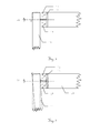
- FIG. 2 shows a connection arrangement according to the invention, for example, an articulated arm, for use with a measuring method according to the invention, wherein the connection arrangement comprises a rotary encoder 9, the rotation of the at least one connecting element 10, for example a first arm member against a receptacle 11, for as the end of a second arm member, captured.
- the measuring component is indirectly connected to the base by a sequence of the connecting elements 10, but according to the invention also measuring machines with only a single connecting element 10 and thus a direct connection of the measuring component to the base by this one connecting element 10 can be realized.
- the rotary encoder 9 in each case comprises a code carrier 12 and a sensor arrangement 13, wherein code carrier 12 and sensor arrangement 13 are rotatable relative to each other about a defined axis of rotation DA as a first degree of freedom.
- code carrier 12 and sensor arrangement 13 are rotatable relative to each other about a defined axis of rotation DA as a first degree of freedom.
- one of the three-dimensional position of the code carrier 12 relative to the sensor assembly 13 dependent code projection is generated on the sensor assembly 13 and at least a portion of the code projection detected by this.
- the rotary encoder 9 is here in a conventional manner from a rigidly connected to the receptacle 11 code carrier 12 with an optically detectable code, which may be formed, for example, as a code-carrying glass or plastic disc, and consisting of one or more detector elements sensor array 13 for detecting the code projection, which may be appropriate in the connecting element 10, constructed.
- the sensor arrangement 13 can have two read heads, each with a row arrangement of optical detector elements.
- the arranged in the connecting element 10 sensor assembly 13 is in the FIGS. 2 to 6 for example, two read heads - eg, as they are known in the prior art.
- the code carrier 12 is assigned as a code carrier with a code plate functioning as a "measuring table" with a code extending in the circumferential direction.
- the code may have a plurality of juxtaposed arranged pattern elements, wherein the Pattern elements - eg in triangular shape - are designed such that the code projection in particular for additional reading of changes in position in non-rotational direction own.
- the arrangement of the sensor arrangement 13 in the connecting element 10 and the mechanically rigid connection of the code carrier 12 with the receptacle 11 is only an example. In particular, this arrangement can also be reversed, ie it is according to the invention also a mechanically rigid arrangement of the code carrier 12 in the connecting element 10 and the mechanically rigid connection of the sensor arrangement 13 with the receptacle 11 can be realized.
- the position measuring device in particular the rotary encoder 9, according to the invention now consider the determined, distorting acting on the angle measurement shifts or tilting of the code carrier in the non-rotational direction not only encoder internal in the angle determination, but as a further Meß eins sizes in addition to the determined angular position to a higher-level evaluation unit, for example, from all Measuring position variables of all the articulated blade in the articulated arm calculates the measuring position
- the rotational position of the code carrier 12 related to the defined rotational axis DA is thus determined and, using this information available for all connecting elements, the current measuring position of the measuring component relative to the base is determined.
- the rotary encoder 9 in contrast to solutions of the prior art, based on the code projection and a position value for at least one further degree of freedom of the code carrier 12 relative to the sensor assembly 13 is determined and taken into account in determining the current measuring position, wherein the position value of a relative Location of the connecting element 10 relative to the receptacle 11 and / or its deformation can be determined.
- the protractors used in the prior art also partially determine lateral displacement or changes in the distance of the code to the detectors, they use this information only to increase accuracy in the angle measurement, i. the determination of the rotational position.
- the positional value for the further degree of freedom is used in order to draw conclusions as to the position or orientation of the connecting element 10 and possibly the acting forces or a deformation of the connecting element 10.
- the code projection can now be read out and changes in position of the code element or code carrier 12 relative to the sensor arrangement 13-ie deviations of a code center-caused by concentricity errors and loads on the rotary joint be derived from the axis of rotation DA -.
- these changes in position of the code carrier 12 relative to the sensor assembly 13 only for correcting an angular position of these two components to each other to be determined according to the invention, these changes in position as sizes, the relative position connecting element 10, for example in the case of an articulated arm of first to the second arm member, taken into account and used in calculating the position of the measurement component relative to the base as measurement position quantities.
- the position values can be determined from the same code projection, which also serves to read out the angular position of the code element relative to the sensor arrangement.
- the determined position values can furthermore also be used for correction and / or calibration in the determination of the angular position.
- FIGS. 3 to 6 show exemplified by load of the rotary joint caused changes in position in the non-rotational direction of the code carrier 12 relative to the sensor assembly 13th
- the code carrier 12 is displaced relative to the sensor arrangement 13 in the direction of the axis of rotation DA.
- a change in position can be derived from the code projection, for example, from a scale change of the code projection detected by the sensor arrangement.
- the associated change in position size can then be transmitted as an axial displacement amount ( ⁇ h) with respect to this rotary joint of the evaluation unit.
- the code carrier 12 is displaced relative to the sensor arrangement 13 and with respect to the axis of rotation DA in the radial direction.
- a change in position can be derived from the code projection, for example, based on displacements of the positions of the pattern elements resolved by the sensor arrangement 13.
- the associated change in position variables can then be transmitted to the evaluation unit as a radial displacement direction (RR) and a radial displacement extent ( ⁇ r) with respect to this rotary joint.
- the code carrier 12 is tilted relative to the sensor arrangement 13 and with respect to the axis of rotation DA.
- a change in position can be derived from the code projection, for example, from a scale ratio of the code projection detected by the first read head to the code projection detected by the second read head.
- the associated change in position variables can be transmitted, for example, as a tilting direction and tilting angle ( ⁇ k) with respect to this rotary joint of the evaluation unit.
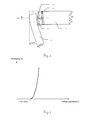
- a function of the bending of one of the arm members depending on the tilting about the axis of rotation derived from deformation laws for solid bodies and / or determined by empirical experiments can be established.
- An example of such a feature is in FIG. 7 represented, wherein a degree of bending ⁇ L of the corresponding arm member - purely schematic and in principle - is plotted against the determined tilt angle p.
- the function can be chosen such that up to a predetermined by a bearing clearance in the pivot tilt angle the extent of the arm-joint bending is set equal to zero.
- FIG. 8 an alternative embodiment according to the invention for a connection arrangement in the form of a rotary joint with two rotary encoders 9 and 9 'is shown.
- the rotary joint is associated with a first rotary encoder 9 and a second rotary encoder 9 ', in which the two optically detectable code disks are arranged as the first and second code carriers 12 and 12' spaced apart on a common axis as a rotation axis DA.
- the two code disks are each assigned a sensor arrangement 13 and 13 'comprising at least two read heads, wherein the sensor arrangements 13 and 13' each detect a code element projection and are arranged opposite one another in the connection element 10.
- Such an arrangement as a protractor and in addition as a measuring instrument for axial and / or radial displacements or tilting of the code carrier allows a highly accurate determination of the exact three-dimensional position or position of the code carrier 12 and 12 'relative to the sensor assemblies 13 and 13'. It is precisely this precisely determined position which is determined on the basis of measurement position variables such as a rotation angle about the rotation axis, a radial displacement direction, a radial displacement extent, an axial displacement extent, a tilt direction and / or a tilting direction.
- the extensive or complete replacement of other sensors in measuring machines can take place, eg of pure length-measuring sensors, so that complete and highly precise determination of the measuring position or spatial position of the measuring component is possible solely by the use of integrally constructed rotary encoders.
- the exclusive use of a single type of sensor makes it possible to simplify the mechanical and electronic design.
- connection arrangements between the arm members are each carried out with two arranged on a common axis of rotation encoders, so that in addition to the relative position of the connecting element with respect to its inclusion in each case also deformations as a deviation from the desired shape, ie both Deformations as well as scale changes, such as enlargement or reduction of length or diameter, can be determined.
- additional sensors can be used, but not directly measure the spatial position but provide additional parameters, such as For example, temperature sensors that allow a conclusion about the temperature-induced deformation of the components.
- FIG. 9 is an example of a code projection generated by a code carrier as a code carrier with circumferentially arranged pattern elements 14 code projection on a sensor array of three offset by 60 ° sensor lines 15a-c.
- the example of the code carrier formed as a bar pattern has a plurality of the same distance from each other in the direction of rotation one behind the other about a pattern center arranged pattern elements 14, which are e.g. are designed as opaque, radially oriented beams. Over beams passing between the bars, a portion of the bar pattern is imaged as light and dark areas on the photosensitive detector elements.
- the outward and inward faces of the beams form two concentric, discontinuous circular lines that embody symmetric patterns to the pattern center.
- the lengths L1 and L2 of the inlets and outlets of the respective bars can be resolved into or out of the spatially resolving area, in particular during a rotation of the bar pattern.
- a radial displacement and / or a tilt can be calculated be determined.
- the position value can be determined by calculation based on a position of at least one of the pattern elements 14, a ratio of positions of a plurality of the pattern elements 14 to each other, or a sequence of positions of a plurality of pattern elements 14 arranged one behind the other.
- the code or the code projection on the sensor arrangement can also be redundant, ie designed to be overdetermined with regard to the variable to be determined, so that the additional information available through the redundancy can be used.
- FIG. 10 shows an embodiment that differs from in FIG. 9 shown embodiment by two offset by 90 ° sensor lines 5d and 5e as a sensor arrangement and by another embodiment of the pattern, in particular the radially aligned to the pattern center out in the direction of rotation arranged pattern elements 14 ', differs.
- the code carrier is here embodied by a translucent glass panel with opaque triangles.
- the code carrier rotatable about the axis could also be formed, for example, in the form of a thin metal disk, which here has triangular-shaped recesses which embody the pattern elements 14 'arranged one behind the other in the direction of rotation.
- the - for example, triangular - execution of the pattern elements 14 ', in which mutually facing side lines of adjacent, successively arranged pattern elements 14' are formed substantially inclined to the radial direction, has by the additional inclination against the radial direction of greater sensitivity with respect to determining displacements or Tilting of the code carrier by the spatially resolving Range up. It even makes it possible to determine such changes in the position of the code carrier via a resolution of the width of a single triangle, which is shown here for the two widths 16 and 17 of the area projected onto the sensor line 15d. Thus, for example, from the width 16 of the projection, the position or its displacement in the radial direction can be detected and its extent determined.
- the sensor arrangement of the rotary encoder can basically and depending on code design and accuracy requirements have both one and two or more read heads or sensor lines, which in principle next sensor lines as linear arrays and surface sensors, ie two-dimensional arrays of pixel sensors can be used.
- these can be arranged, for example, in the circumferential direction offset from one another by 180 °, wherein they can be arranged offset by 90 ° in each case in the case of four reading heads in the circumferential direction.
- With three read heads they can be arranged offset by 120 °.
- sensor arrangements of the rotary encoder can be realized with, for example, at least four read heads, which are offset in the circumferential direction with different angles offset from one another, so that For example, all angular distances differ from each other, in particular to each other in any ratio of multiples.
- a, in particular single surface sensor can be used, which is arranged on the axis of rotation or this and an adjacent area detected and thus covers a large angular range in the near-axis region or the full angle range.
- a code carrier code patterns can also be attached to two opposite end faces, to which in turn in each case an area sensor covering the axis of rotation is associated.
- area codes which are detected by a corresponding sensor are, for example, from WO 2008/019855 known.
Abstract
Description
Die Erfindung betrifft ein Messverfahren für eine oberflächenvermessende Messmaschine nach dem Oberbegriff des Anspruchs 1, eine Verbindungsanordnung, insbesondere Kipp- oder Drehverbindung, für eine Messmaschine nach dem Oberbegriff des Anspruchs 8 und eine Koordinatenmessmaschine mit Gelenkarm nach Anspruch 14.The invention relates to a measuring method for a surface-measuring measuring machine according to the preamble of
Messverfahren und -maschinen, wie beispielsweise Koordinatenmessgeräte oder -maschinen, z.B. mit Gelenkarm sind seit langem bekannt. Beispielsweise werden diese Geräte zum mit hoher Genauigkeit erfolgenden Vermessen von Objektoberflächen verwendet, insbesondere in der fertigenden Industrie, für die das Vermessen und Überprüfen von Werkstückoberflächen hohe Bedeutung hat.Measuring methods and machines, such as coordinate measuring machines or machines, e.g. with articulated arm have long been known. For example, these devices are used for high accuracy surveying of object surfaces, especially in the manufacturing industry, for which the measurement and inspection of workpiece surfaces has great importance.
Gattungsgemässe 3D-Koordinatenmess-Gelenkarme werden beispielsweise in
3D-Koordinatenmess-Gelenkarme besitzen eine in einem Referenzkoordinatensystem bekannt und fix positionierte Basis als ein Ende des Gelenkarms und ein gegenüberliegendes bewegliches Messende, an dem eine Messkomponente bzw. ein Messtaster angeordnet ist. Als Standardtaster kann eine taktile Probe verwendet werden, welche in Kontakt mit einem Messpunkt einer Objektoberfläche gebracht werden kann und beispielsweise aus einer Rubinkugel besteht, die auf einem Messstab montiert ist.3D coordinate measuring articulated arms have a base that is known and fixedly positioned in a reference coordinate system as one end of the articulated arm and an opposite movable measuring end on which a measuring component or a probe is arranged. As a standard probe, a tactile sample can be used, which can be brought into contact with a measuring point of an object surface and, for example consists of a ruby ball, which is mounted on a dipstick.
Alternativ dazu sind als Messkomponenten auch optische Sensoren bekannt, die beispielsweise als Punktmesser oder als Scanner, d.h. als eine Objektoberfläche kontinuierlich und z.B. linienweise abtastend, ausgeführt sein können. Im Speziellen können als solche optische Sensoren Triangulations-Sensoren oder interferometrische Messanordnungen verwendet werden. Des Weiteren wird beispielsweise in der Europäischen Patentanmeldung Nr.
Zwischen den beiden Enden des Gelenkarms sind mehrere zueinander schwenkbar und/oder verdrehbar sowie gegebenenfalls gegeneinander verschiebbar verbundene Glieder oder Armabschnitte angeordnet, sodass das Messende mit der Messkomponente, das auch als Tast-Glied bezeichnet wird, innerhalb eines Raumabschnitts frei bewegbar ist. Dazu sind die Glieder des Arms mittels Gelenken sowie gegebenenfalls mittels Aufhängungen, die eine Linearverschiebung ermöglichen, miteinander verbunden. Weiters sind den Gelenken bzw. Aufhängungen Lagemesseinrichtungen zugeordnet, sodass jeweils eine Stellung oder Orientierung der Glieder zueinander, also eine relative Lage jeweils zwischen den Gliedern, gemessen werden kann. Beispielsweise werden dafür Winkelmesser und/oder Längenmesser eingesetzt, die als Messgrössen Längen, Dreh- oder Schwenkwinkel ermitteln.Between the two ends of the articulated arm a plurality of mutually pivotable and / or rotatable and possibly mutually slidably connected members or arm portions are arranged so that the measuring end with the measuring component, which is also referred to as a Tast-member, is freely movable within a space section. For this purpose, the limbs of the arm are connected to each other by means of joints and possibly by means of suspensions which enable a linear displacement. Furthermore, the joints or suspensions are associated with position measuring devices, so that in each case a position or orientation of the members to each other, so a relative position between each of the members, can be measured. For example, for this protractor and / or length are used, which determine lengths, rotation or tilt angle as measured variables.
Aus der Kenntnis einer momentanen Messstellung der Glieder, d.h. der jeweiligen relativen Lagen der Glieder zueinander sowie eines der Glieder zur Basis, kann die Orientierung der einzelnen Armelemente und der Messkomponente relativ zur Basis in einem Referenzkoordinatensystem bestimmt werden. Das Bestimmen der Position der Messkomponente erfolgt im Allgemeinen durch eine Auswerteeinheit, welche diese durch die jeweiligen Lagemesseinrichtungen gemessen Messgrössen übermittelt bekommt und daraus die Position des Messkomponente ableitet. Zum Beispiel können dafür speziell für diese Anwendung programmierte Computer oder Recheneinheiten verwendet werden. Durch die über die Basis gewährleistbare Bezugnahme auf das externe Referenzkoordinatensystem können neben der Orientierung auch die Position der Armelemente und der Messkomponente, d.h. Ort und Ausrichtung im Raum, bestimmt werden.From the knowledge of a current measuring position of the links, i. the respective relative positions of the members to each other and one of the members to the base, the orientation of the individual arm elements and the measurement component relative to the base in a reference coordinate system can be determined. The determination of the position of the measuring component is generally carried out by an evaluation unit which receives these measured variables measured by the respective position measuring devices and derives therefrom the position of the measuring component. For example, specially programmed computers or arithmetic units may be used for this application. The reference to the external reference coordinate system, which can be ensured via the base, can be used not only for orientation, but also for the position of the arm elements and the measuring component, i. Location and orientation in space, to be determined.
Gattungsgemäss sind den Drehgelenken eines Gelenkarms jeweils optisch-elektronische Winkelmesser zugeordnet, anhand welcher jeweils eine relative Drehlage der beiden über das Gelenk verbundenen Glieder ermittelt wird. Das Gelenk besteht im allgemeinen aus den beiden miteinander drehbar verbundenen Arm-Gliedern, zwischen denen ein Drehgeber oder Winkelmesser angeordnet ist. Der optisch-elektronische Winkelmesser oder Drehgeber dient hierbei zum Messen einer momentanen relativen Drehlage seiner Drehlager-Komponenten zueinander, und damit mittelbar der beiden Arm-Glieder. Er weist hierfür einen Codeträger oder ein Codeelement, das an einem der beiden Arm-Glieder angeordnet ist, und eine Sensoranordnung auf, die entsprechend an dem anderen Arm-Glied angebracht ist.According to the invention, the hinges of an articulated arm are each assigned opto-electronic protractors, by means of which in each case a relative rotational position of the two links connected via the joint is determined. The joint consists generally of the two rotatably connected arm members, between which a rotary encoder or protractor is arranged. The opto-electronic protractor or rotary encoder serves to measure a momentary relative rotational position of its pivot bearing components to each other, and thus indirectly the two arm members. He has for this purpose a code carrier or a code element which is arranged on one of the two arm members, and a sensor arrangement which is correspondingly attached to the other arm member.
Der Codeträger ist dabei nun derart im Drehgelenk gelagert, dass eine relative Rotationsbewegung des Codeträgers relativ zu der Sensoranordnung um eine Drehachse ermöglicht wird. Das gegenüber der Aufnahme eines ersten Arm-Gliedes rotierbare Element des zweiten Gelenkarm-Glieds, die Sensoranordnung sowie der darin gegeneinander der Sensoranordnung rotierbar gelagerte Codeträger können dabei als Drehlager-Komponenten bezeichnet werden.The code carrier is now mounted in such a way in the rotary joint, that a relative rotational movement of the code carrier is made possible relative to the sensor arrangement about an axis of rotation. The element rotatable relative to the receptacle of a first arm member of the second articulated arm member, the sensor assembly and the mutually rotatably mounted therein the sensor assembly code carrier can be referred to as a rotary bearing components.
Bei solchen opto-elektronischen Ausführungsformen werden Musterelemente als Code des Codeträgers optisch auf die Sensoranordnung aus einem oder mehreren Leseköpfen, z.B. CCD- oder CMOS-Zeilen- oder Flächensensoren, abgebildet, wie beispielsweise in der
Über solche Verfahren und Vorrichtungen ist es bei entsprechenden Vorkehrungen sogar möglich mit einer Messgenauigkeit in der Grössenordnung einiger weniger Winkelsekunden einen Vollkreis in über eine Million Einheiten aufzulösen.By means of such methods and devices, it is even possible with appropriate precautions to resolve a full circle in more than one million units with a measurement accuracy of the order of magnitude of a few angular seconds.
Um derartig hohe Genauigkeiten erreichen zu können, muss einerseits die Sensoranordnung lagestabil zum Lager angeordnet sein. Andererseits ist eine hohe Mass- und Formhaltigkeit des Codeträgers, insbesondere die Anordnung und Ausbildung des Codeelements auf dem Codeträger - mit in Drehrichtung hintereinander um ein Musterzentrum angeordneten Musterelementen - eine zwingende Voraussetzung. Neben partiellen Teilungsungenauigkeiten, die auf Abweichungen der vorgegebenen Abstände zwischen einzelnen hintereinander angeordneten Musterelemente und/oder auf Abweichungen der Abmessungen der Musterelemente selbst zurückzuführen sind, verunmöglicht in der Praxis oft eine Beabstandung des Musterzentrums von der Drehachse, eine so genannte Exzentrizität, ein Erreichen geforderter Genauigkeiten. Aufgrund nur schwer vermeidbarer und in der Praxis stets gegebener Fertigungstoleranzen weist jeder Codeträger eine Exzentrizität auf. Rundlaufabweichungen des Lagers bzw. ein Lagerspiel können zudem einen Beitrag zur Exzentrizität liefern. Wirken beim Bestimmen der Tastposition bzw. der Drehwinkel auf die Drehgelenke des Gelenkarms nennenswerte Belastungen durch Kräfte, so können abhängig von den Belastungen ebenso dauerhafte oder temporäre Exzentrizitäten sowie andersartige Lageänderungen des Codeträgers gegenüber der Aufnahme des Drehgelenks auftreten.In order to be able to achieve such high accuracies, on the one hand the sensor arrangement must be arranged in a positionally stable manner relative to the bearing. On the other hand, a high dimensional and dimensional stability of the code carrier, in particular the arrangement and design of the code element on the code carrier - with in the direction of rotation successively arranged around a pattern center pattern elements - a mandatory requirement. In addition to partial division inaccuracies, which are due to deviations of the predetermined distances between individual successively arranged pattern elements and / or deviations in the dimensions of the pattern elements themselves, in practice often makes a spacing of the pattern center of the rotation axis, a so-called eccentricity, reaching required accuracies. Due to difficult to avoid and always given in practice manufacturing tolerances, each code carrier has an eccentricity. Run-out deviations of the bearing or a bearing clearance can also contribute to the eccentricity. Acting in determining the touch position or the angle of rotation on the hinges of the articulated arm significant loads by forces, so may occur depending on the loads as well as permanent or temporary eccentricities and other changes in position of the code carrier relative to the inclusion of the rotary joint.
Verfahren und Vorrichtungen zur Bestimmung des Drehwinkels und Herauskalibrierung solcher unerwünschten Lageänderungen gegenüber der Idealposition, beispielsweise durch Belastungen auf das Drehgelenk oder durch Lagerfehler und/oder Rundlaufabweichungen, werden unter anderem in der Europäischen Patentanmeldung Nr.
Dabei ist aus der
Über die Detektorelemente ein und desselben Detektors werden Positionen der abgebildeten Musterelemente aufgelöst. In einem ersten Schritt werden über aufgelöste Positionen wenigstens eines Musterelements Auswirkungen einer Exzentrizität des Musterzentrums zur Achse auf das Bestimmen eines Drehwinkels rechnerisch ermittelt. In einem zweiten Schritt wird unter Berücksichtigung der ermittelten Auswirkungen der Drehwinkel über die aufgelösten Positionen hintereinander angeordneter Musterelemente genau bestimmt.Positions of the imaged pattern elements are resolved via the detector elements of one and the same detector. In a first step, effects of eccentricity of the pattern center relative to the axis on the determination of a rotation angle are determined by computation over resolved positions of at least one pattern element. In a second step, the angle of rotation over the resolved positions of successively arranged pattern elements is determined exactly taking into account the determined effects.
In einer Weiterbindung dieses Verfahrens werden bei dem ersten Schritt über einen Zwischenschritt hintereinander angeordnete Musterelemente zu wenigstens zwei Gruppen zusammengefasst und über die aufgelösten Einzelpositionen der jeweils zusammengefassten Musterelemente wenigstens zwei Gruppenpositionen rechnerisch ermittelt. Über die wenigstens zwei ermittelten Gruppenpositionen werden dann Auswirkungen der Exzentrizität auf das Bestimmen des Drehwinkels rechnerisch ermittelt. Über die ermittelten Gruppenpositionen kann dies mit höherer Genauigkeit erfolgen.In a further development of this method, in the first step, pattern elements arranged behind one another are combined into at least two groups via an intermediate step, and at least two group positions are determined by calculation over the resolved individual positions of the respectively combined pattern elements. The effects of the eccentricity on the determination of the angle of rotation are then calculated by way of the at least two determined group positions. This can be done with higher accuracy via the determined group positions.
In der Internationalen Patentanmeldung
Des Weiteren wird darin erläutert, dass - neben den Einflussgrössen, die zu einem direkten Exzentrizitätsbeitrag in der Ebene der Sensoranordnung führen, wie z.B. der translatorischen Verschiebung der Lagerwelle - mit geeigneten Winkelmessköpfen auch die Bewegung in der Richtung der Drehachse ermittelt werden kann. Durch die Abstandsänderung des Codeelements zur Sensoranordnung ändert sich der Projektionsmassstab des Codes. Diese Änderung des Projektionsmassstabes kann als Mass für die Abstandsänderung bzw. die Position in axialer Richtung verwendet werden. Werden für zwei Detektorelemente die Abstände zur Codescheibe als Codeelement bestimmt, so kann auch die Verkippung der Achse bestimmt werden.Furthermore, it explains that, in addition to the factors which lead to a direct contribution to eccentricity in the plane of the sensor arrangement, such as e.g. the translational displacement of the bearing shaft - with suitable angle measuring heads and the movement in the direction of the axis of rotation can be determined. The change in the distance of the code element to the sensor arrangement changes the projection scale of the code. This change in the projection scale can be used as a measure of the change in distance or the position in the axial direction. If the distances to the code disk are determined as a code element for two detector elements, the tilting of the axis can also be determined.
Dabei ist aufgezeigt, dass die mindestens zwei Leseköpfe derart miteinander kooperieren, dass ein durch Belastungen des Drehgelenks verursachter Fehler bei der Drehwinkelmessung verringert wird.It is shown that the at least two read heads cooperate with each other in such a way that an error caused by loads of the rotary joint error in the rotation angle measurement is reduced.
Beispielsweise sind dazu zwei in Umfangsrichtung um 180°, drei um jeweils 120° oder alternativ vier um jeweils 90° versetzte Leseköpfe vorgesehen.For example, two are provided in the circumferential direction by 180 °, three by 120 ° or alternatively four by 90 ° offset read heads.
Wie bereits oben angedeutet ist also bei diesen Verfahren bzw. Vorrichtungen des Standes der Technik stets ein Berücksichtigen, Eliminieren, Herauskalibrieren oder Kompensieren von Fehlern, die die Winkelmessung beeinflussen, ausschliesslich für das Bestimmen des Drehwinkels vorgesehen. Als Fehler werden z.B. Taumelfehler durch eine Neigung der Rotationsachse, Exzentrizitätsfehler durch Fertigungstoleranzen oder ein Lagerspiel sowie weitere Fehler, die beispielsweise durch Belastungen des Drehgelenks hervorgerufen werden, berücksichtigt. Eine eigene Bestimmung und Quantifizierung der Einflussgrössen und deren Weiterverarbeitung ausserhalb des Drehgebers erfolgt nicht.As already indicated above, therefore, in these prior art methods or devices, consideration, elimination, calibration or compensation of errors that influence the angle measurement are always provided exclusively for determining the angle of rotation. As errors, e.g. Tumbling through an inclination of the axis of rotation, eccentricity due to manufacturing tolerances or a bearing clearance and other errors that are caused for example by loads on the swivel joint, taken into account. A separate determination and quantification of the influencing variables and their further processing outside of the rotary encoder does not take place.
Jedoch entstehen bei Koordinatenmessmaschinen mit einem Drehgelenke aufweisenden Gelenkarm durch die beschriebenen Fehlereinflüsse wie Belastungen der Drehgelenke - über ein fehlerhaftes Bestimmen der Winkellage hinaus - weitere Fehler im Rahmen der Bestimmung der Messposition der Messkomponente. Nämlich treten in der Praxis - über die eigentlich durch das Drehgelenk vorgesehene Rotation hinaus - weitere Lageänderungen des Codeträgers gegenüber der Aufnahme auf, insbesondere Axialverschiebungen, Radialverschiebungen oder Verkippungen, welche verschiedene Ursachen haben können. Zwar handelt es sich dabei um minimale Lageänderungen, dennoch führen diese bei den inzwischen geforderten Genauigkeiten für die Positionsbestimmung zu nennenswerten Fehlern.However, in the case of coordinate measuring machines with an articulated arm having a swivel joint, further errors occur during the determination of the measuring position of the measuring component due to the described error influences such as loads on the swivel joints-beyond an erroneous determination of the angular position. Namely, in practice - beyond the rotation actually provided by the rotary joint - further changes in position of the code carrier relative to the receptacle, in particular axial displacements, radial displacements or tilting, which may have different causes. Although these are minimal changes in position, they nevertheless lead to noteworthy errors in the meanwhile required accuracies for determining the position.
Eine Aufgabe der Erfindung ist daher das Bereitstellen eines verbesserten Messverfahrens für eine oberflächenvermessende Messmaschine, insbesondere für eine Koordinatenmessmaschine mit Dreh- oder Kippgelenke aufweisendem Gelenkarm, zum Bestimmen der Messposition einer Messkomponente.An object of the invention is therefore to provide an improved measuring method for a Surface measuring measuring machine, in particular for a coordinate measuring machine with articulated arm having pivoting or tilting joints, for determining the measuring position of a measuring component.
Eine weitere Aufgabe ist das Bereitstellen einer verbesserten Koordinatenmessmaschine mit einem Drehgelenke als Verbindungsanordnungen aufweisenden Gelenkarm.A further object is the provision of an improved coordinate measuring machine with an articulated arm having hinges as connecting arrangements.
Insbesondere soll dabei unter geringem Hardware-Modifikationsaufwand seitens des Gelenkarms ein Bestimmen der Messkomponente-Messposition mit höherer Genauigkeit ermöglicht werden.In particular, it should be possible to determine the measuring component measuring position with higher accuracy with little hardware modification effort on the part of the articulated arm.
Diese Aufgaben werden durch die Verwirklichung der kennzeichnenden Merkmale der unabhängigen Ansprüche gelöst. Merkmale, die die Erfindung in alternativer oder vorteilhafter Weise weiterbilden, sind den abhängigen Patentansprüchen zu entnehmen.These objects are achieved by the realization of the characterizing features of the independent claims. Features which further develop the invention in an alternative or advantageous manner can be found in the dependent claims.
Das erfindungsgemässe Messverfahren für eine oberflächenvermessende Messmaschine, z.B. für eine Koordinatenmessmaschine mit Drehgelenke aufweisendem Gelenkarm zum Bestimmen einer Messposition einer Messkomponente, löst sich von Verfahren des Standes der Technik, bei welchen stets lediglich im Rahmen des Bestimmens einer Winkelstellung des Dreh- oder Kippgelenks ein Berücksichtigen oder Kompensieren von Fehlereinflüssen - wie z.B. durch Belastung bedingte Verschiebungen oder Verkippungen der Drehachse - vorgesehen sind, wobei die Arm-Glieder als Verbindungselemente von der Basis bis zur Messkomponente als unbeeinflusst betrachtet werden.The measuring method according to the invention for a surface-measuring measuring machine, e.g. for a coordinate measuring machine with hinged joint arm for determining a measuring position of a measuring component, dissolves from methods of the prior art, in which always only in the context of determining an angular position of the pivot or tilting joint taking into account or compensate for error influences - such. load-induced displacements or tilting of the axis of rotation - are provided, wherein the arm members are considered as connecting elements from the base to the measuring component as uninfluenced.
Hingegen werden gemäss der Erfindung solche Lageänderungen des in einer Aufnahme rotierbar gelagerten Codeträgers eines Drehgelenks gegenüber der zugeordneten Sensoranordnung explizit bestimmt und als zusätzliche Messgrössen, die die Messstellung der Arm-Glieder des Gelenkarms beschreiben, zum Ableiten der Messposition der Messkomponente relativ zu einer Basis verwendet. Dies bedeutet, dass eine im Dreh- oder Kippgelenk als Verbindungsanordnung beispielsweise durch Belastungen hervorgerufene Lageänderung der beiden über das Drehgelenk verbundenen Arm-Glieder - die über eine Drehlage-Änderung hinaus geht - in ihrem Ausmass bestimmt und bei der Ermittlung der relativen Lage der beiden Arm-Glieder zueinander berücksichtigt wird. Ebenso kann erfindungsgemäss aus diesen Lagewerten auf Verformungen oder Grössenänderungen von Komponenten geschlossen werden.By contrast, according to the invention, such changes in position of the rotatably mounted in a recording code carrier of a rotary joint relative to the associated Sensor arrangement explicitly determined and used as additional measures that describe the measurement position of the arm members of the articulated arm, for deriving the measuring position of the measuring component relative to a base. This means that in the rotary or tilting joint as a connection arrangement, for example, caused by strain change in position of the two connected via the hinge arm members - which goes beyond a rotational position change - determined in its extent and in determining the relative position of the two arm -Glieder each other is taken into account. Likewise, according to the invention, it is possible to infer these deformations from deformations or changes in the size of components.
Das Bestimmen der Lageänderungen wie
- einer Verschiebung des Codeträgers gegenüber der Sensoranordnung in radialer Richtung relativ zur Drehachse,
- einer Verschiebung des Codeträgers gegenüber der Sensoranordnung in Richtung der Drehachse und/oder
- einer Verkippung des Codeträgers gegenüber der Aufnahme,
- a displacement of the code carrier relative to the sensor arrangement in the radial direction relative to the axis of rotation,
- a displacement of the code carrier relative to the sensor arrangement in the direction of the axis of rotation and / or
- a tilting of the code carrier relative to the recording,
bzw. von mit diesen Lageänderungen verbundenen Lageänderungs-Grössen erfolgt anhand einer optisch-elektronischen Lagemesseinrichtung zwischen dem Codeträger und der Sensoranordnung, insbesondere anhand eines ohnehin bereits dem Drehgelenk zugeordneten optisch-elektronischen Winkelmessers.or by associated with these changes in position change in position variables is carried out using an optical-electronic position measuring device between the code carrier and the sensor array, in particular on the basis of an already associated with the hinge optical-electronic protractor.
Dazu weist die Lagemesseinrichtung einen Code, der an einem der Drehgelenk-Komponenten - nämlich direkt oder über eine eigene Komponente - aufgebracht ist, und eine Sensoranordnung aus mindestens einem Lesekopf auf. Die Sensoranordnung ist dabei an der jeweils anderen Drehgelenk-Komponente angeordnet und erfasst eine anhand des Codeträgers erzeugte Code-Projektion. Als Code-Projektion ist dabei eine Projektion mindestens eines Teiles eines optisch erfassbaren Codes, den das Codeelement aufweist, zu verstehen. Insbesondere kann als Codeträger eine eigene Codescheibe dienen, die mit einem der Gelenkarm-Glieder verbunden ist. Alternativ kann sich aber auch der Code direkt auf einem der Arm-Glieder befinden, so dass diese strukturell als Codeträger dient.For this purpose, the position measuring device has a code, which is applied to one of the rotary joint components - namely directly or via a separate component - and a sensor arrangement of at least one read head. The sensor arrangement is at the other Swivel component arranged and detects a code projection generated by the code carrier. In this case, a projection of at least part of an optically detectable code, which the code element has, is to be understood as code projection. In particular, serve as a code carrier own code disc, which is connected to one of the articulated arm members. Alternatively, however, the code can also be located directly on one of the arm members, so that it structurally serves as a code carrier.
Gattungsgemässe Codeträger und Sensoranordnungen, wobei anhand einer ausgelesenen Code-Projektion die beschriebenen Lageänderungen des Codes relativ zur Sensoranordnung ermittelt werden können, sind aus dem Stand der Technik hinlänglich bekannt. Allerdings werden diese Lageänderungen gemäss Vorrichtungen und Verfahren des Standes der Technik lediglich zur Kalibrierung und somit Verbesserung einer Winkelmessung verwendet. Nicht jedoch werden dabei die aus der Code-Projektion abgeleiteten Verschiebungen oder Verkippungen zum Beschreiben der dreidimensionalen relativen Stellung der Komponenten des Drehgelenks zueinander verwendet. Somit wird im Rahmen bisheriger Messpositionsbestimmungen bei Gelenkarmen stets von der idealistischen Annahme ausgegangen, dass das Drehgelenk ausschliesslich eine relative Drehbewegung der Drehgelenk-Komponenten gegeneinander - also eine Bewegung mit einem Freiheitsgrad - erlaubt.Generic code carrier and sensor arrangements, wherein the described changes in position of the code relative to the sensor arrangement can be determined on the basis of a read-out code projection, are well known from the prior art. However, in accordance with prior art devices and methods, these changes in position are merely used to calibrate and thus improve angle measurement. However, the displacements or tilts derived from the code projection are not used to describe the three-dimensional relative position of the components of the hinge relative to one another. Thus, in the context of previous measurement position determinations for articulated arms, it is always assumed that the idealistic assumption is that the rotary joint permits only a relative rotational movement of the rotary joint components relative to one another, ie a movement with one degree of freedom.
Erfindungsgemäss wird nunmehr für den Drehgeber anhand der Code-Projektion ein Lagewert für mindestens einen weiteren Freiheitsgrad des Codeträgers relativ zu der ihm zugeordneten Sensoranordnung ermittelt und beim Bestimmen der aktuellen Messposition der Messkomponente bzw. des Tasters berücksichtigt, wobei aus dem Lagewert eine relative Lage des Verbindungselementes gegenüber der damit verbundenen Aufnahme bzw. dessen Deformation bestimmt werden. Dies bedeutet, dass erfindungsgemäss die über die Rotation hinausgehenden Lageveränderungen des Codeträgers mit der Lage bzw. Orientierung und einer möglichen Deformation eines Verbindungselementes der Messmaschine, z.B. eines Armelementes, in Beziehung gesetzt wird.According to the invention, a position value for at least one further degree of freedom of the code carrier relative to the sensor arrangement assigned to it is now determined for the rotary encoder based on the code projection and taken into account in determining the current measuring position of the measuring component or of the probe, wherein the position value Relative position of the connecting element relative to the associated recording or its deformation can be determined. This means that, according to the invention, the changes in position of the code carrier beyond the rotation are related to the position or orientation and a possible deformation of a connecting element of the measuring machine, eg an arm element.
Die Bestimmung der Messposition kann hierbei sowohl auch modellbasierten Ansätzen beruhen, bei denen die geometrischen und materialabhängigen Grössen der Verbindungselemente, wie z.B. deren Länge und Eigen- oder ein wirkendes Fremdgewicht, berücksichtigt werden, als auch eine auf Kalibrierungen basierende Lösung verwendet werden, bei der bekannten Positionen und Orientierungen entsprechende Lagewerte zugeordnet werden, die ihrerseits wieder eine Basis für eine beschreibende Funktion liefern können oder aber auch in Look-up-Tabellen abgelegt werden können. Naturgemäss können diese Ansätze jedoch auch kombiniert werden, z.B. indem auf Basis einer Modellierung zusätzliche Kalibrierungen in ausgewählten Messpositionen erfolgen. Zudem können auch durch andere Sensoren, wie z.B. Temperatursensoren, bestimmte Grössen im Modell ergänzende Verwendung finden.The determination of the measuring position here can also be based on model-based approaches in which the geometrical and material-dependent sizes of the connecting elements, such as, for example, whose length and intrinsic or an effective foreign weight are taken into account, as well as a solution based on calibrations are used in the known positions and orientations corresponding position values are assigned, which in turn can provide a basis for a descriptive function or in Look -up tables can be dropped. By nature, however, these approaches may also be combined, e.g. by performing additional calibrations in selected measurement positions based on modeling. In addition, other sensors, such as e.g. Temperature sensors, certain sizes in the model find complementary use.
Durch die erfindungsgemässe Verwendung der ermittelten Lageänderungen zum Beschreiben der exakten relativen Stellung der Drehgeber- bzw. Verbindungsanordnungs-Komponenten zueinander und somit als weitere Messgrössen, die die relative Stellung der Gelenkarm-Glieder angebenden und beim Berechnen der Messposition des Tasters relativ zur Basis berücksichtigt werden, wird unter geringem Hardware-Modifikationsaufwand seitens des Gelenkarms ein Bestimmen der Messkomponenten-Messposition mit höherer Genauigkeit ermöglicht.By the inventive use of the determined changes in position for describing the exact relative position of the encoder or connection arrangement components to each other and thus as additional measures that the relative position of the articulated arm-indicating and considered in calculating the measuring position of the probe relative to the base, is determined with little hardware modification effort by the articulated arm allows the measuring component measuring position with higher accuracy.
Beispielsweise wird erfindungsgemäss eine auftretende Verkippung des Codeträgers eines Drehgelenks um die eigentliche Rotationsachse in ihrem Ausmass erfasst und direkt als aktuelle relative Messstellung der über das Drehgelenk verbundenen Glieder zueinander berücksichtigt und somit bei der Bestimmung der Messposition des Tasters miteinbezogen.For example, according to the invention, an occurring tilting of the code carrier of a rotary joint about the actual axis of rotation is detected to its extent and taken directly into account as the current relative measuring position of the links connected via the rotary joint and thus included in the determination of the measuring position of the button.
Bei modellbasierten Ansätzen kann je nach Ausführung des Verbindungselementes dieses als starr oder aber als in Grenzen deformierbar betrachtet werden. Dementsprechend kann jegliche Veränderung als nur im Gelenk bzw. der Verbindungsanordnung auftretend betrachtet werden oder aber es wird auch eine Veränderung der Komponenten betrachtet. So ist es modellierbar, dass je nach Anordnung von Drehgeberachse und Achse des Verbindungselementes und in Kenntnis des Eigengewichtes des Verbindungselementes sowie in Abhängigkeit von der Orientierung benachbarter Verbindungselemente bzw. Arm-Glieder auch eine Aufteilung in lagebedingte und deformationsbedingte Anteile erfolgt. So sind bei Anbringung des Drehgebers auf der Längsachse des Verbindungselementes und dessen senkrechter Position die Durchbiegung und damit Deformation sowie auch lastbedingte Verkippungen des Codeträgers gegenüber der Sensoranordnung minimal, wobei in hängender und in stehender Position des Armgliedes entgegengesetzte Längsverschiebungen, d.h. Translationen in axialer Richtung, auftreten. Damit sind auch Deformationen der einzelnen Komponenten einer Messmaschine identifizierbar und in ihrer Auswirkung bestimmbar.In model-based approaches, depending on the design of the connecting element, this can be considered rigid or deformable within limits. Accordingly, any change may be considered to occur only in the joint or connection assembly, or a change in the components may be considered. Thus, it is possible to model that, depending on the arrangement of the rotary encoder axis and the axis of the connecting element and in knowledge of the dead weight of the connecting element and depending on the orientation of adjacent connecting elements or arm members also a division into positional and deformation-related shares. Thus, when mounting the encoder on the longitudinal axis of the connecting element and its vertical position, the deflection and thus deformation as well as load-related tilting of the code carrier relative to the sensor assembly minimal, in opposite and in a standing position of the arm member opposite longitudinal displacements, ie translations in the axial direction occur , Deformations of the individual components of a measuring machine can thus be identified and their effect can be determined.
Insbesondere bei auswechselbaren Messkomponenten kann durch deren unterschiedlichen Gewichte auch eine entsprechend abweichende Beeinflussung der Verbindungsanordnungen erfolgen, die durch den erfindungsgemässen Absatz bestimmbar ist.In particular, with replaceable measuring components can be carried out by the different weights and a correspondingly different influence on the connection arrangements, which can be determined by the paragraph of the invention.
Hierbei ist auch zu berücksichtigen, dass bei den hier erforderlichen hochpräzisen Anwendungen bereits thermisch bedingte Veränderungen, wie z.B. Längen- oder Radiusänderungen, Auswirkungen auf die Messposition bedingen, die ebenfalls durch den erfindungsgemässen Ansatz berücksichtigt bzw. erkannt werden können.It should also be borne in mind that, in the case of the high-precision applications required here, already thermally induced changes, such as e.g. Length or radius changes, affecting the measurement position condition, which can also be considered or recognized by the inventive approach.
Die Sensoranordnung der Lagemesseinrichtung kann insbesondere aus mindestes zwei Leseköpfen bestehen. Beispielsweise sind als Sensoranordnung zwei Leseköpfe um 90° in Umfangsrichtung versetzt angeordnet oder alternativ drei Leseköpfe mit einem Versatz von jeweils 60°. Die Leseköpfe können dabei in bekannter Weise z.B. als Zeilensensoren mit einer Vielzahl von aneinander gereihten Detektorelementen ausgebildet sein.The sensor arrangement of the position measuring device may in particular consist of at least two read heads. For example, as a sensor arrangement two read heads offset by 90 ° in the circumferential direction or alternatively three read heads with an offset of 60 °. The read heads can in a known manner, e.g. be formed as line sensors with a plurality of juxtaposed detector elements.
Als Codeelement bzw. Codeträger kann insbesondere eine Codescheibe mit einem optisch auslesbaren Code verwendet werden, z.B. im Durchlichtverfahren. Dabei kann der Code eine Vielzahl von in Umfangsrichtung hintereinander angeordneter Musterelemente aufweisen, wobei die Gesamtheit der Musterelemente sowohl einen inkrementellen als auch einen absoluten Code darstellen kann. Alternativ kann sich der Code jedoch auch auf anderen Träger befinden, z.B. auf der Stirnfläche von Gehäusekomponenten, die dann bspw. im Auflichtverfahren beleuchtet werden können.As code element or code carrier, in particular, a code disc with an optically readable code can be used, e.g. in transmitted light. In this case, the code can have a multiplicity of pattern elements arranged one behind the other in the circumferential direction, wherein the entirety of the pattern elements can represent both an incremental and an absolute code. Alternatively, however, the code may be on other carriers, e.g. on the face of housing components, which can then be illuminated, for example, in the incident light process.
Vorzugsweise kann gemäss der Erfindung als die Lagemesseinrichtung ein optisch-elektronischer Drehgeber, wie er in einigen Drehgelenken von Gelenkarmen aus dem Stand der Technik bereits ohnehin vorhanden ist, verwendet werden. Insbesondere kann jedoch auch dem Drehgelenk - zusätzlich zum nach dem Stand der Technik ausgebildeten und dem Drehgelenk zugeordneten Winkelencoder ein weiterer Drehgeber oder eine andere funktional ähnliche Form der Kombination von Codeträger und Sensoranordnung als eine optisch-elektronische Lagemesseinrichtung vorgesehen sein, wobei diese speziell zum Erfassen der Lageänderungen des Codeträgers relativ zur Sensoranordnung dient.Preferably, according to the invention, as the position measuring device, an optical-electronic rotary encoder, as it already exists in some hinges of articulated arms of the prior art, are used. In particular, however, the rotary joint may be provided as an optical-electronic position measuring device, in addition to the angular encoder assigned to the prior art and assigned to the rotary joint, a further rotary encoder or another functionally similar form of combination of code carrier and sensor arrangement, this being particularly suitable for detecting the Changes in position of the code carrier relative to the sensor arrangement is used.
Wie bereits oben beschrieben, werden dabei folgende Lageänderungen des Codeträgers gegenüber der Aufnahme - und somit eines ersten, den Codeträger darstellenden Arm-Glieds relativ zu einem zweiten, die Aufnahme aufweisenden Arm-Glied - ermittelt und beim Ableiten der exakten Relativstellung der Glieder zueinander berücksichtigt:
- eine Verschiebung des Codeträgers gegenüber der Sensoranordnung in - bezüglich der Drehachse - radialer Richtung,
- eine Verschiebung des Codeträgers gegenüber der Sensoranordnung in - bezüglich der Drehachse - axialer Richtung und/oder
- eine Verkippung des Codeträgers relativ zur
Sensoranordnung.
- a displacement of the code carrier relative to the sensor arrangement in - with respect to the axis of rotation - radial direction,
- a displacement of the code carrier relative to the sensor arrangement in - with respect to the axis of rotation - axial direction and / or
- a tilt of the code carrier relative to
Sensor arrangement.
Als damit verknüpfte Lageänderungs-Grössen können zum Beispiel
- eine Radial-Verschiebungs-Richtung (RR) und ein Radial-Verschiebungs-Ausmass (Δr),
- ein Axial-Verschiebungs-Ausmass (Δh) und
- eine Verkippungs-Richtung und ein Verkippungs-Winkel (Δk) bestimmt werden. Die Lageänderungs-Grössen werden - neben den weiteren Armstellungs-Messgrössen, die die Messstellung der Arm-Glieder bezeichnen - zueinander in Bezug gesetzt, woraus die Messposition der Messkomponente relativ zur Basis abgeleitet wird.
- a radial displacement direction (RR) and a radial displacement amount (Δr),
- an axial displacement amount (Δh) and
- a tilt direction and a tilt angle (Δk) be determined. The position change quantities are - in addition to the other Armstellungs measured variables, which designate the measuring position of the arm members - related to each other, from which the measuring position of the measuring component is derived relative to the base.
Die gemäss der Erfindung ausgebildete Koordinatenmessmaschine weist dafür eine Auswerteeinheit auf, durch die das Miteinander-Verknüpfen der durch einzelne Gliederstellungsmesser erfassten Armstellungs-Messgrössen - darunter erfindungsgemäss auch die Lageänderungs-Grössen bezüglich des mindestens einen Drehgelenks - und daraus das Ableiten der Messposition der Messkomponente erfolgt.For this purpose, the coordinate measuring machine designed according to the invention has an evaluation unit, by means of which the arm position measured variables detected by individual articulation position measuring devices - including, according to the invention, the position change quantities with respect to the at least one rotary joint - and therefrom the measuring position of the measuring component are derived.
Das erfindungsgemässe Messverfahren und die erfindungsgemässe Verbindungsanordnung sowie eine erfindungsgemässe Koordinatenmessmaschine werden nachfolgend anhand von in den Zeichnungen schematisch dargestellten konkreten Ausführungsbeispielen rein beispielhaft näher beschrieben, wobei auch auf weitere Vorteile der Erfindung eingegangen wird. Im Einzelnen zeigen:
- Fig.1
- eine gattungsgemässe Koordinatenmessmaschine mit Dreh- bzw. Kippgelenke aufweisendem Gelenkarm;
- Fig.2
- eine erfindungsgemässe Verbindungsanordnung eines Gelenkarms;
- Fig.3
- die erfindungsgemässe Verbindungsanordnung aus
Figur 4 mit einer dargestellten Axialverschiebung des Codeträgers;
- Fig.4
- die erfindungsgemässe Verbindungsanordnung aus
Figur 4 mit einer dargestellten Radialverschiebung des Codeträgers; - Fig.5
- die erfindungsgemässe Verbindungsanordnung aus
Figur 4 mit einer dargestellten Verkippung des Codeträgers; - Fig.6
- die erfindungsgemässe Verbindungsanordnung aus
Figur 4 mit einer Verkippung des Codeträgers sowie mit einer Verbiegung der Arm-Glieder; - Fig.7
- die erfindungsgemässe Verbindungsanordnung mit einer weiteren Ausführungsform für einen diesem zugeordneten Drehgeber;
- Fig.8
- eine zum Auslesen von Verschiebungen und/oder Verkippungen des Codeträgers gegenüber der Aufnahme geeignete Code-Projektion auf eine Sensoranordnung;
- Fig.9
- eine zum Auslesen von Verschiebungen und/oder Verkippungen des Codeträgers gegenüber der Sensoranordnung geeignete Code-Projektion; und
- Fig.10
- eine weitere zum Auslesen von Verschiebungen und/oder Verkippungen des Codeträgers gegenüber der Sensoranordnung geeignete Code-Projektion.
- Fig.1
- a generic coordinate measuring machine with pivoting or tilting joints exhibiting articulated arm;
- Fig.2
- an inventive connection arrangement of an articulated arm;
- Figure 3
- the inventive connection arrangement
FIG. 4 with an illustrated axial displacement of the code carrier;
- Figure 4
- the inventive connection arrangement
FIG. 4 with an illustrated radial displacement of the code carrier; - Figure 5
- the inventive connection arrangement
FIG. 4 with an illustrated tilting of the code carrier; - Figure 6
- the inventive connection arrangement
FIG. 4 with a tilting of the code carrier and with a bending of the arm members; - Figure 7
- the inventive connection arrangement with a further embodiment for a rotary encoder associated therewith;
- Figure 8
- a code projection suitable for reading out displacements and / or tilting of the code carrier relative to the recording on a sensor arrangement;
- Figure 9
- a code projection suitable for reading out displacements and / or tilting of the code carrier relative to the sensor arrangement; and
- Figure 10
- another code projection suitable for reading out displacements and / or tilting of the code carrier relative to the sensor arrangement.
Ein erstes der Glieder 5a ist dabei relativ zur Basis 4 beweglich an dieser befestigt, ein zweites der Glieder 5b ist am ersten Glied 5a relativ zu diesem beweglich befestigt, usw. Das siebte Glied 5g weist ein Messkomponente 6 auf und bildet insgesamt als Strukturelement das Tast-Glied TG. Die Messkomponente 6 ist somit innerhalb eines Raumabschnitts frei bewegbar und kann z.B. durch einen Benutzer händisch in eine Messposition gebracht werden, wobei der mechanische Kontakt zur Basis 4 durch die Abfolge der Verbindungselemente gewährleistet ist. Beispielsweise ist der Taster 6 als Rubinkugel zum Kontaktieren eines zu vermessenden Punktes einer Objektoberfläche ausgebildet, wobei aber auch berührungslos messende Systeme in gleicher Weise angeordnet und verwendet werden können. Alternativ können jedoch auch weitere aus dem Stand der Technik bekannte Messkomponenten anstelle des taktilen Tasters verwendet werden. So können als Messkomponente beispielsweise optische Sensoren - insbesondere ein optischer Distanzmesser, z.B. interferometrische Messanordnungen, ein Laserscanner oder eine Kamera zum Abtasten der Oberfläche Verwendung finden.A first one of the links 5a is movably attached thereto relative to the
Als Messposition werden beispielsweise die Koordinaten eines Referenzpunktes der Messkomponente 6 und insbesondere zusätzlich eine aktuelle Ausrichtung der Messkomponente 6 in der jeweiligen aktuellen Messposition angegeben.As a measuring position, for example, the coordinates of a reference point of the
Die Glieder 5a-5f sind dabei zur einfacheren Unterscheidung in
Jeweils den Gelenken bzw. Aufhängungen zugeordnet sind mehrere Lagemesseinrichtungen 8a-8f zum Messen von Stellungen jeweils der Glieder 5a-5f zueinander. Beispielsweise sind als die Lagemesseinrichtungen 8a-8f optisch-elektronische Drehgeber als Lagemesseinrichtungen 8a,8c,8d sowie Längenmesser als Lagemesseinrichtungen 8b,8e vorgesehen, die zum Messen von mit der relativen Lage der Glieder verknüpften Armstellungs-Messgrössen α,β,γ,δ,ε,a,b,c ausgebildet sind. Als Armstellungs-Messgrössen α,β,γ,δ,ε,a,b,c werden somit also jeweils Winkel α,β,γ,δ,ε und Längenauslenkungen a,b,c zwischen den Gliedern 5a-5f gemessen.Associated with each of the joints or suspensions are a plurality of position measuring devices 8a-8f for measuring positions of the respective elements 5a-5f relative to one another. For example, as the position measuring devices 8a-8f, optical-electronic rotary encoders are provided as
Eine Auswerteeinheit 7 ist dabei zum Empfang der für eine Messposition ermittelten Armstellungs-Messgrössen α,β,γ,δ, ε,a,b,c ausgebildet. Anhand dieser die relative Stellungen jeweils der Arm-Glieder zueinander angebenden Armstellungs-Messgrössen α,β,γ,δ,ε,a,b,c leitet die Auswerteeinheit die Messposition bzw. die Koordinaten der Messkomponente 6 ab und zeigt diese z.B. auf einem Display an.An
Der Drehgeber 9 umfasst jeweils einen Codeträger 12 und eine Sensoranordnung 13, wobei Codeträger 12 und Sensoranordnung 13 um eine definierte Drehachse DA als einem ersten Freiheitsgrad gegeneinander rotierbar sind. Hierzu wird eine von der dreidimensionalen Lage des Codeträgers 12 relativ zur Sensoranordnung 13 abhängigen Code-Projektion auf der Sensoranordnung 13 erzeugt und mindestens ein Teil der Code-Projektion durch diese erfaßt. Der Drehgeber 9 ist hierbei in an sich bekannter Weise aus einem mit der Aufnahme 11 starr verbundenen Codeträger 12 mit einem optisch erfassbaren Code, der beispielsweise als codetragende Glas- oder Kunststoffscheibe ausgebildet sein kann, und der aus einem oder mehreren Detektorelementen bestehenden Sensoranordnung 13 zur Erfassung der Code-Projektion, die entsprechend im Verbindungselement 10 angebracht sein kann, aufgebaut. Die Sensoranordnung 13 kann dafür zum Beispiel zwei Leseköpfe mit jeweils einer Zeilenanordnung von optischen Detektorelementen aufweisen. Die im Verbindungselement 10 angeordnete Sensoranordnung 13 besteht in den
Zusätzlich zu einer Winkellage werden gemäss der Erfindung weitere Lagen des ersten Arm-Glieds zum zweiten Arm-Glied beim Bestimmen der relativen Messstellung berücksichtigt, wobei der als Codescheibe ausgeführte Codeträger 12 als "Messtisch" dient. Das bedeutet, dass die dreidimensionale Lage der Codescheibe gegenüber der Sensoranordnung 13, beispielsweise aus einen Schattenwurf der Codescheibe, ausgelesen wird, wobei die Codescheibe wie eine Tischplatte fungiert, deren durch eine Deckenlampe auf dem Boden erzeugter Schatten abhängig ist von ihrem Standpunkt und ihrer Neigung gegenüber dem Boden. Dabei ist eine Modifikation der bereits in Koordinatenmessmaschinen vorhandenen Hardware nur bedingt notwendig. So muss die Lagemesseinrichtung, insbesondere der Drehgeber 9, gemäss der Erfindung nun die ermittelten, auf die Winkelmessung verzerrend wirkenden Verschiebungen bzw. Verkippungen des Codeträgers in Nicht-Rotationsrichtung nicht nur drehgeberintern bei der Winkelbestimmung berücksichtigen, sondern als weitere Messstellungs-Grössen zusätzlich zur ermittelten Winkellage an eine übergeordnete Auswerteeinheit, die beispielsweise aus allen Messstellungs-Grössen von sämtlichen im Gelenkarm vorhandenen Gliederlagemesser die Messposition berechnetIn addition to an angular position, further layers of the first arm member to the second arm member are taken into account in determining the relative measuring position according to the invention, wherein the
Anhand der Code-Projektion wird somit die auf die definierte Drehachse DA bezogene Drehlage des Codeträgers 12 ermittelt und unter Verwendung dieser für alle Verbindungselemente verfügbaren Information die aktuelle Messposition der Messkomponente relativ zur Basis bestimmt. Für den Drehgeber 9 wird, im Gegensatz zu Lösungen des Stands der Technik, anhand der Code-Projektion auch ein Lagewert für mindestens einen weiteren Freiheitsgrad des Codeträgers 12 relativ zur Sensoranordnung 13 ermittelt und beim Bestimmen der aktuellen Messposition berücksichtigt, wobei aus dem Lagewert eine relative Lage des Verbindungselementes 10 gegenüber der Aufnahme 11 und/oder dessen Deformation bestimmt werden. Die im Stand der Technik verwendeten Winkelmesser bestimmen zwar teilweise ebenfalls laterale Verschiebung oder Abstandsänderungen des Codes zu den Detektoren, nutzen diese Information jedoch lediglich zur Genauigkeitssteigerung bei der Winkelmessung, d.h. der Bestimmung der Drehlage. Hingegen wird erfindungsgemäss der Lagewert für den weiteren Freiheitsgrad verwendet, um daraus Schlüsse hinsichtlich der Lage bzw. Orientierung des Verbindungselementes 10 sowie ggf. der wirkenden Kräfte bzw. einer Deformation des Verbindungselementes 10 zu ziehen.Based on the code projection, the rotational position of the
Wie zum Beispiel in den oben zitierten Dokumenten des Standes der Technik beschrieben ist, kann nun die Code-Projektion ausgelesen und daraus - durch Rundlauffehler und Belastungen des Drehgelenks hervorgerufene - Lageänderungen des Codeelements bzw. Codeträgers 12 relativ zur Sensoranordnung 13 - d.h. beispielsweise Abweichungen eines Codezentrums von der Drehachse DA - abgeleitet werden. Im Gegensatz zur nach dem Stand der Technik bekannten Verwendung dieser Lageänderungen des Codeträgers 12 gegenüber der Sensoranordnung 13 lediglich zum Korrigieren einer zu bestimmenden Winkelstellung dieser beiden Komponenten zueinander, werden erfindungsgemäss diese Lageänderungen als Grössen, die die relative Stellung Verbindungselementes 10, z.B. im Fall eines Gelenkarmes des ersten zum zweiten Armglied angibt, berücksichtigt und beim Berechnen der Position der Messkomponente gegenüber der Basis als Messstellungs-Grössen verwendet. Somit werden auch über einen Drehwinkel hinausgehende Lageänderungen des Codeträgers 12 gegenüber der Sensoranordnung 13 aus der erfassten Code-Projektion explizit ermittelt und zum Bestimmen der Messposition verwendet. Zwar werden durch eine entsprechende, präzise Lagerung des Codeträgers 12 solche Verschiebungen und Verkippungen im Wesentlichen verhindert, jedoch wirken sich bereits minimale Verschiebungen bzw. Verkippungen auf die Genauigkeit für das Bestimmen der Messposition des Tasters aus. Die zwar grundsätzlich unerwünschten, jedoch nicht vollständig vermeidbaren Lageänderungen werden somit nicht nur in Kauf genommen, sondern bestimmt und als Information zur Beschreibung des Gesamtzustandes des mechanischen Systems der Messmaschine genutzt. Somit wird zum einen die Veränderung zwischen den der Aufnahme und damit dem einen Arm-Glied zugeordneten Komponenten und den Komponenten des Verbindungselementes als dem anderen Arm-Glied ermittelt, so dass Veränderungen im Gelenk bzw. der Verbindungsanordnung quantifiziert und berücksichtigt werden können. Zum anderen kann aus dem Ausmass der Veränderung und den Winkelstellungen auf die wirkenden Kräfte geschlossen werden, so dass gewichtsbedingte Deformationen von Komponenten oder deren Verbindungen ermittelt werden können. Zudem können auch thermische oder alterungsbedingte Änderungen in der Verbindungsanordnung erfasst und berücksichtigt werden.As described, for example, in the above-cited prior art documents, the code projection can now be read out and changes in position of the code element or
Erfindungsgemäss erfolgt hierzu ein Ermitteln wenigstens einer, insbesondere aber aller der folgenden Lageänderungen bzw. Lagewerte:
- eine Verschiebung in radialer Richtung relativ zur Drehachse DA,
- eine Verschiebung in Richtung der Drehachse DA und/oder
- eine Verkippung um die Drehachse DA.
- a displacement in the radial direction relative to the axis of rotation DA,
- a shift in the direction of the axis of rotation DA and / or
- a tilt about the axis of rotation DA.
Insbesondere können die Lagewerte aus derselben Code-Projektion bestimmt werden, die auch zum Auslesen der Winkellage des Codeelements relativ zur Sensoranordnung dient. Ebenso können erfindungsgemäss die ermittelten Lagewerte weiterhin auch zur Korrektur und/oder Kalibrierung bei der Bestimmung der Winkellage verwendet werden.In particular, the position values can be determined from the same code projection, which also serves to read out the angular position of the code element relative to the sensor arrangement. Likewise, according to the invention, the determined position values can furthermore also be used for correction and / or calibration in the determination of the angular position.
In
In
In
Wie in
Dabei wird angenommen, dass als Mass für eine Verbiegung der über das Drehgelenk verbundenen Arm-Glieder - modellhaft und in guter Näherung - ein Ausmass der ermittelten Verkippung herangezogen werden kann.It is assumed that a measure of the bending of the arm members connected via the swivel joint can be used as a measure of deflection of the determined tilting in a model and to a good approximation.
Beispielsweise kann dafür eine anhand von Deformationsgesetzen für Festkörper hergeleitete und/oder durch empirische Experimente festgelegte Funktion der Verbiegung eines der Arm-Glieder in Abhängigkeit der Verkippung um die Drehachse aufgestellt werden. Ein Beispiel für eine solche Funktion ist in
In
Dabei ist dem Drehgelenk ein erster Drehgeber 9 und ein zweiter Drehgeber 9' zugeordnet, bei denen die beiden optisch erfassbaren Codescheiben als erster und zweiter Codeträger 12 und 12' voneinander beabstandet auf einer gemeinsamen Achse als Drehachse DA angeordnet sind. Den beiden Codescheiben ist jeweils eine Sensoranordnung 13 und 13' aus mindestens zwei Leseköpfen zugeordnet, wobei die Sensoranordnungen 13 und 13' jeweils eine Codeelement-Projektion erfassen und sich gegenüberliegend im Verbindungselement 10 angeordnet sind.In this case, the rotary joint is associated with a first
Eine solche Anordnung als Winkelmesser und zusätzlich als Messinstrument für axiale und/oder radiale Verschiebungen bzw. Verkippungen des Codeträgers ermöglicht ein hoch präzises Ermitteln der exakten dreidimensionalen Lage bzw. Stellung der Codeträger 12 und 12' gegenüber den Sensoranordnungen 13 und 13'. Eben diese exakt ermittelte Stellung, die anhand von Messstellungs-Grössen wie einem Drehwinkel um die Drehachse, einer Radial-Verschiebungs-Richtung, einem Radial-Verschiebungs-Ausmass, einem Axial-Verschiebungs-Ausmass, einer Verkippungs-Richtung und/oder einem Verkippungs-Winkel erfasst wird, kann unter Berücksichtigung der starren Kopplung der Codeträger 12 und 12' auf der einen Seite und der Sensoranordnungen 13 und 13' auf der anderen Seite zueinander in Beziehung gesetzt werden. So können Ausdehnung und Längenänderung der gemeinsamen Achse oder des Gehäuses des Verbindungselementes anhand der Abstandsänderung der Codeträger 12 und 12' zu den jeweiligen Sensoranordnungen 13 und 13' erkannt und quantitativ bestimmt werden. Ebenso kann bei als starr angenommener Achse und gegenläufigen Verkippungen von Codeträger 12, 12' und Sensoranordnungen 13, 13' in den Drehgebern 9 und 9' auf eine Verbiegung des Verbindungselementes 10 geschlossen werden. Bei einer gleichgerichteten Verkippung kann hingegen ein weitgehend starres Verhalten des Verbindungselementes 10 und dessen gesamthafte Bewegung geschlossen werden.Such an arrangement as a protractor and in addition as a measuring instrument for axial and / or radial displacements or tilting of the code carrier allows a highly accurate determination of the exact three-dimensional position or position of the
Erfindungsgemäss kann insbesondere der weitgehende oder vollständige Ersatz von anderen Sensoren in Messmaschinen erfolgen, z.B. von reinen längenmessenden Sensoren, so dass eine vollständige und hochpräzise Bestimmung der Messposition bzw. räumlichen Lage der Messkomponente alleine durch die Verwendung von einheitlich aufgebauten Drehgebern möglich wird. Durch die damit mögliche ausschliessliche Verwendung eines einzigen Sensortyps kann der mechanische und elektronische Aufbau vereinfacht werden. Insbesondere kann in einem Gelenkarm mehrere oder auch jede der Verbindungsanordnungen zwischen den Arm-Gliedern mit jeweils zwei auf einer gemeinsamen Drehachse angeordneten Drehgebern ausgeführt werden, so dass neben der relativen Lage des Verbindungselementes gegenüber seiner Aufnahme jeweils auch Deformationen als Abweichung von der Sollform, d.h. sowohl Verformungen als auch Skalenänderungen, wie z.B. Vergrösserung oder Verkleinerung von Länge oder Durchmesser, bestimmt werden können. Somit ist es auch möglich, die relative räumliche Lage aller Komponenten zueinander ausschliesslich durch Drehgeber zu bestimmen, wobei ergänzend weitere Sensoren verwendet werden können, die jedoch nicht direkt die räumliche Lage messen sondern zusätzliche Parameter bereitstellen, wie z.B. Temperatursensoren, die einen Schluss über die temperaturbedingte Verformung der Komponenten erlauben.According to the invention, in particular the extensive or complete replacement of other sensors in measuring machines can take place, eg of pure length-measuring sensors, so that complete and highly precise determination of the measuring position or spatial position of the measuring component is possible solely by the use of integrally constructed rotary encoders. The exclusive use of a single type of sensor makes it possible to simplify the mechanical and electronic design. In particular, in an articulated arm more or each of the connection arrangements between the arm members are each carried out with two arranged on a common axis of rotation encoders, so that in addition to the relative position of the connecting element with respect to its inclusion in each case also deformations as a deviation from the desired shape, ie both Deformations as well as scale changes, such as enlargement or reduction of length or diameter, can be determined. Thus, it is also possible to determine the relative spatial position of all components to each other exclusively by encoders, with additional sensors can be used, but not directly measure the spatial position but provide additional parameters, such as For example, temperature sensors that allow a conclusion about the temperature-induced deformation of the components.
In
Das beispielhaft als Balkenmuster ausgebildete Muster des Codeträgers weist eine Vielzahl im selben Abstand zueinander in Drehrichtung hintereinander um ein Musterzentrum angeordneter Musterelemente 14 auf, die z.B. als lichtundurchlässige, radial ausgerichtete Balken ausgebildet sind. Über zwischen den Balken hindurch tretende Strahlen wird ein Teil des Balkenmusters als helle und dunkle Bereiche auf den lichtempfindlichen Detektorelementen abgebildet.The example of the code carrier formed as a bar pattern has a plurality of the same distance from each other in the direction of rotation one behind the other about a pattern center arranged
Zudem bilden die nach aussen und die nach innen gerichteten Stirnseiten der Balken zwei konzentrische, diskontinuierliche Kreislinien, die zum Musterzentrum symmetrische Muster verkörpern. Über die Sensorzeilen 15a-c als Detektorelemente lassen sich hier, insbesondere während einer Drehung des Balkenmusters, die Längen L1 und L2 der Ein- und Austritte der jeweiligen Balken in bzw. aus dem ortsauflösenden Bereich auflösen. Mit den auf diese Weise aufgelösten Positionen können dann beispielsweise eine Radialverschiebung und/oder eine Verkippung rechnerisch ermittelt werden. Grundsätzlich kann der Lagewert rechnerisch anhand einer Position wenigstens eines der Musterelemente 14, eines Verhältnisses von Positionen mehrerer der Musterelemente 14 zueinander oder einer Abfolge von Positionen mehrerer hintereinander angeordneter Musterelemente 14 bestimmt werden. Dabei kann der Code bzw. die Code-Projektion auf die Sensoranordnung auch redundant, d.h. hinsichtlich der zu bestimmenden Grösse als überbestimmt ausgelegt werden, so dass die durch die Redundanz zur Verfügung stehende Zusatzinformation verwendet werden kann.In addition, the outward and inward faces of the beams form two concentric, discontinuous circular lines that embody symmetric patterns to the pattern center. By way of the
Die - beispielsweise dreieckige - Ausführung der Musterelemente 14', bei der einander zugewandte Seitenlinien benachbarter, hintereinander angeordneter Musterelemente 14' wesentlich gegen die Radialrichtung geneigt ausgebildet sind, weist durch die zusätzliche Neigung gegen die Radialrichtung eine grössere Sensitivität in Bezug auf ein Ermitteln von Verschiebungen oder Verkippungen des Codeträgers durch den ortsauflösenden Bereich auf. Sie ermöglicht sogar ein Ermitteln solcher Lageänderungen des Codeträgers über ein Auflösen der Breite eines einzigen Dreiecks, was hier für die beiden Breiten 16 und 17 des auf die Sensorzeile 15d projizierten Bereichs dargestellt wird. So kann beispielsweise aus der Breite 16 der Projektion die Lage bzw. deren Verschiebung in hier radialer Richtung erkannt und deren Ausmass bestimmt werden. Selbstverständlich ist es auch möglich, solche Lageänderungen über die Abstände zwischen den Dreiecken zu ermitteln. Durch die hier dreieckförmige Form der in Richtung des Musterzentrums gerichteten Musterelemente können hier hingegen - im Vergleich zu rechteckförmigen Musterelementen - weniger hintereinander angeordnete Musterelemente vorgesehen werden, wodurch eine geringere Auflösung erzielbar ist.The - for example, triangular - execution of the pattern elements 14 ', in which mutually facing side lines of adjacent, successively arranged pattern elements 14' are formed substantially inclined to the radial direction, has by the additional inclination against the radial direction of greater sensitivity with respect to determining displacements or Tilting of the code carrier by the spatially resolving Range up. It even makes it possible to determine such changes in the position of the code carrier via a resolution of the width of a single triangle, which is shown here for the two
Die Sensoranordnung des Drehgebers kann jedoch grundsätzlich und in Abhängigkeit von Codegestaltung und Genauigkeitsanforderungen sowohl einen als auch zwei oder mehr Leseköpfe bzw. Sensorzeilen aufweisen, wobei grundsätzlich neben Sensorzeilen als Lineararrays auch Flächensensoren, d.h. zweidimensionale Anordnungen von Bildpunktsensoren Verwendung finden können. Bei zwei oder mehr Leseköpfen können diese bspw. in Umfangsrichtung 180° versetzt zueinander angeordnet sein, wobei diese bei vier Leseköpfe in Umfangsrichtung jeweils um 90° versetzt angeordnet werden können. Bei drei Leseköpfen aufweist, die können diese jeweils um 120° versetzt angeordnet sein. Neben der Aufteilung der Anordnung mit gleichen Winkelabständen zwischen den Leseköpfen bzw. Sensorkomponenten können jedoch Sensoranordnungen des Drehgebers mit bspw. wenigstens vier Leseköpfen realisiert werden, die in Umfangsrichtung mit unterschiedlichen Winkeln versetzt zueinander angeordnet sind, so dass sich z.B. alle Winkelabstände voneinander unterscheiden, insbesondere zueinander in keinem Verhältnis von Vielfachen stehen.However, the sensor arrangement of the rotary encoder can basically and depending on code design and accuracy requirements have both one and two or more read heads or sensor lines, which in principle next sensor lines as linear arrays and surface sensors, ie two-dimensional arrays of pixel sensors can be used. In the case of two or more reading heads, these can be arranged, for example, in the circumferential direction offset from one another by 180 °, wherein they can be arranged offset by 90 ° in each case in the case of four reading heads in the circumferential direction. With three read heads, they can be arranged offset by 120 °. In addition to the division of the arrangement with equal angular intervals between the read heads or sensor components, however, sensor arrangements of the rotary encoder can be realized with, for example, at least four read heads, which are offset in the circumferential direction with different angles offset from one another, so that For example, all angular distances differ from each other, in particular to each other in any ratio of multiples.
Ebenso kann beispielsweise auch ein, insbesondere einziger Flächensensor Verwendung finden, der auf der Drehachse angeordnet ist bzw. diese und einen angrenzenden Bereich erfasst und somit eine grossen Winkelbereich im achsnahen Bereich oder auch den vollen Winkelbereich abdeckt. Insbesondere können bei einem Codeträger auch an zwei gegenüberliegenden Stirnflächen Codemuster angebracht sein, denen wiederum jeweils ein die Drehachse überdeckender Flächensensor zugeordnet ist. Solche Anordnungen mit flächigen Codes, die von einem entsprechenden Sensor erfasst werden, sind beispielsweise aus der
Es versteht sich, dass diese dargestellten Figuren nur Beispiele möglicher Ausführungsformen schematisch darstellen.It is understood that these illustrated figures represent only examples of possible embodiments schematically.
Claims (15)
dadurch gekennzeichnet, dass
für den wenigstens einen Drehgeber (9,9') anhand der Code-Projektion ein Lagewert für mindestens einen weiteren Freiheitsgrad des Codeträgers (12,12') relativ zur Sensoranordnung (13,13') ermittelt und beim Bestimmen der aktuellen Messposition berücksichtigt wird, wobei aus dem Lagewert eine relative Lage des Verbindungselementes (10) gegenüber der Aufnahme (11) und/oder dessen Deformation als Form- oder Grössenänderung bestimmt werden.
characterized in that
for the at least one rotary encoder (9, 9 '), based on the code projection, a position value for at least one further degree of freedom of the code carrier (12, 12') relative to the sensor arrangement (13, 13 ') is determined and taken into account in determining the current measuring position, wherein from the position value, a relative position of the connecting element (10) relative to the receptacle (11) and / or its deformation are determined as a change in shape or size.
als Lagewert
□ in relativ zur Drehachse (DA) radialer Richtung und/oder
□ in Richtung der Drehachse (DA)
und/oder
Ruhelage relativ zur Sensoranordnung (13,13'), ermittelt wird.
as positional value
□ in relative to the axis of rotation (DA) radial direction and / or
□ in the direction of the axis of rotation (DA)
and or
Resting position relative to the sensor arrangement (13,13 '), is determined.
dadurch gekennzeichnet, dass
für den wenigstens einen Drehgeber 9,9') Drehlage, Auslenkung und Verkippung und somit die Lage des Codeträgers (12,12') relativ zur Sensoranordnung (13,13') in allen sechs Freiheitsgraden ermittelt werden.Measuring method according to claim 1 or 2,
characterized in that
for the at least one rotary encoder 9,9 ') rotational position, deflection and tilting and thus the position of the code carrier (12,12') relative to the sensor arrangement (13,13 ') are determined in all six degrees of freedom.
dadurch gekennzeichnet, dass
für den wenigstens einen Drehgeber (9,9') eine Aufteilung in deformations- und relativlagebedingte Anteile anhand der Orientierung eines mit der Aufnahme (11) verbundenen weiteren Verbindungselementes erfolgt.Measuring method according to one of the preceding claims,
characterized in that
for the at least one rotary encoder (9,9 '), a division into deformation-related and relatively position-related components on the basis of the orientation of the recording (11) connected to another connecting element takes place.
dadurch gekennzeichnet, dass
für wenigstens einen zweiten Drehgeber (9') dessen Drehlage und dessen Lagewert ermittelt und beim Bestimmen der räumlichen Lage der Messkomponente (6) berücksichtigt werden.Measuring method according to one of the preceding claims,
characterized in that
for at least one second rotary encoder (9 ') whose rotational position and its position value determined and taken into account in determining the spatial position of the measuring component (6).
dadurch gekennzeichnet, dass
die Messposition anhand der ausschliesslich über die Drehlagen und Lagewerte der wenigstens zwei Drehgeber (9,9') abgeleiteten räumlichen Lage der Verbindungselemente bestimmt wird.Measuring method according to claim 5,
characterized in that
the measuring position is determined on the basis of the spatial position of the connecting elements derived exclusively via the rotational positions and position values of the at least two rotary encoders (9, 9 ').
dadurch gekennzeichnet, dass
der Drehgeber (9,9') wenigstens zwei Codeträger (12,12') aufweist, die um dieselbe, insbesondere auf einer gemeinsamen Drehachse drehbar und voneinander beabstandet angeordnet sind, und für jeden der Codeträger (12,12') anhand der jeweiligen Code-Projektion ein Lagewert ermittelt wird, wobei aus der Verknüpfung der Lagewerte der beiden Codeträger (12,12') eine relative Lage des Verbindungselementes (10) gegenüber der Aufnahme (11) und/oder dessen Deformation bestimmt wird.Measuring method according to one of the preceding claims,
characterized in that
the rotary encoder (9, 9 ') has at least two code carriers (12, 12') which are arranged rotatable about the same, in particular on a common rotational axis, and for each of the code carriers (12, 12 ') on the basis of the respective code Projection of a position value is determined, from the combination of the positional values of the two code carrier (12,12 ') a relative position of the connecting element (10) relative to the receptacle (11) and / or its deformation is determined.
dadurch gekennzeichnet, dass
der Drehgeber (9,9') zur aus der Code-Projektion erfolgenden Bestimmung und Bereitstellung von wenigstens einem Lagewert bezüglich mindestens einem von fünf weiteren Freiheitsgraden der dreidimensionalen Lage des Codeträgers (12,12') relativ zur Sensoranordnung (13,13'), nämlich
der Drehachse (DA),
ausgebildet ist, so dass aus dem Lagewert eine relative Lage des Verbindungselementes (10) gegenüber der Aufnahme (11) und/oder dessen Deformation als Form-oder Grössenänderung bestimmbar ist.
characterized in that
the rotary encoder (9, 9 ') for determining from the code projection and providing at least one position value with respect to at least one of five further degrees of freedom of the three-dimensional position of the code carrier (12, 12') relative to the sensor arrangement (13, 13 '), namely
the axis of rotation (DA),
is formed, so that from the position value, a relative position of the connecting element (10) relative to the receptacle (11) and / or its deformation as shape or size change can be determined.
dadurch gekennzeichnet, dass
die Sensoranordnung (13,13') des Drehgebers (9,9') wenigstens zwei Leseköpfe aufweist, die in Umfangsrichtung 180° versetzt zueinander angeordnet sind, insbesondere vier Leseköpfe aufweist, die in Umfangsrichtung jeweils um 90° versetzt zueinander angeordnet sind.Connecting arrangement according to claim 8,
characterized in that
the sensor arrangement (13, 13 ') of the rotary encoder (9, 9') has at least two read heads which are offset in the circumferential direction by 180 ° relative to each other, in particular has four read heads, which are offset in the circumferential direction by 90 ° relative to one another.
dadurch gekennzeichnet, dass
die Sensoranordnung (13,13') des Drehgebers (9,9') drei Leseköpfe aufweist, die in Umfangsrichtung jeweils um 120° versetzt angeordnet sind.Connecting arrangement according to claim 8,
characterized in that
the sensor arrangement (13, 13 ') of the rotary encoder (9, 9') has three read heads, which are arranged offset in the circumferential direction by 120 ° in each case.
dadurch gekennzeichnet, dass
die Sensoranordnung (13,13') des Drehgebers (9,9') wenigstens vier Leseköpfe aufweist, die in Umfangsrichtung mit unterschiedlichen Winkeln versetzt zueinander angeordnet sind.Connecting arrangement according to claim 8,
characterized in that
the sensor arrangement (13, 13 ') of the rotary encoder (9, 9') has at least four read heads which are arranged offset in the circumferential direction at different angles relative to one another.
der Drehgeber (9,9') wenigstens zwei Codeträger (12,12') aufweist, die um dieselbe, insbesondere auf einer gemeinsamen Drehachse (DA) drehbar und voneinander beabstandet angeordnet sind, wobei den beiden Codeträgern (12,12') jeweils eine Sensoranordnung (13,13') aus mindestens zwei Leseköpfen zugeordnet ist, die jeweils eine Codeelement-Projektion erfassen und sich gegenüberliegend angeordnet sind.Connecting arrangement according to one of claims 8 to 11, characterized in that
the rotary encoder (9, 9 ') has at least two code carriers (12, 12') which are arranged so as to be rotatable and spaced apart from one another, in particular on a common axis of rotation (DA), wherein the two code carriers (12, 12 ') each have one Sensor arrangement (13,13 ') is assigned from at least two read heads, each detecting a code element projection and are arranged opposite each other.
der Codeträger (12,12') mehrere Musterelemente (14,14') als Code aufweist und die Sensoranordnung (13,13') projizierte Positionen mehrerer Musterelemente (14,14') der Code-Projektion auflöst, wobei der mindestens eine Lagewert rechnerisch bestimmt wird anhand
the code carrier (12, 12 ') has a plurality of pattern elements (14, 14') as code and the sensor arrangement (13, 13 ') resolves projected positions of a plurality of pattern elements (14, 14') of the code projection, the at least one position value being calculated is determined by
dadurch gekennzeichnet, dass
die Messposition ausschliesslich anhand der Drehlagen und Lagewerte der Drehgeber (9,9') der Verbindungsanordnungen (10) bestimmt wird.Coordinate measuring machine (1) according to claim 14,
characterized in that
the measuring position is determined exclusively on the basis of the rotational positions and position values of the rotary encoders (9, 9 ') of the connecting arrangements (10).
Priority Applications (11)
| Application Number | Priority Date | Filing Date | Title |
|---|---|---|---|
| EP10157931A EP2372302A1 (en) | 2010-03-26 | 2010-03-26 | Measuring method for a surface measuring machine |
| EP11709710.5A EP2553386B1 (en) | 2010-03-26 | 2011-03-21 | Measuring method for a surface measuring machine |
| CN201180015769.5A CN102822619B (en) | 2010-03-26 | 2011-03-21 | Measurement method for a surface-measuring measuring machine |
| AU2011231747A AU2011231747B2 (en) | 2010-03-26 | 2011-03-21 | Measurement method for a surface-measuring measuring machine |
| KR1020127026845A KR101480330B1 (en) | 2010-03-26 | 2011-03-21 | Measurement method for a surface-measuring measuring machine |
| JP2013501745A JP5546677B2 (en) | 2010-03-26 | 2011-03-21 | Measuring method for surface measuring measuring machine |
| BR112012024351A BR112012024351B1 (en) | 2010-03-26 | 2011-03-21 | measuring process for a surface measuring machine, connection arrangement and coordinate measuring machine |
| PCT/EP2011/054192 WO2011117171A1 (en) | 2010-03-26 | 2011-03-21 | Measurement method for a surface-measuring measuring machine |
| US13/636,628 US11454499B2 (en) | 2010-03-26 | 2011-03-21 | Measurement method for a surface-measuring measuring machine |
| CA2793572A CA2793572C (en) | 2010-03-26 | 2011-03-21 | Measurement method for a surface-measuring measuring machine |
| US17/888,266 US11796314B2 (en) | 2010-03-26 | 2022-08-15 | Measurement method for a surface-measuring measuring machine |
Applications Claiming Priority (1)
| Application Number | Priority Date | Filing Date | Title |
|---|---|---|---|
| EP10157931A EP2372302A1 (en) | 2010-03-26 | 2010-03-26 | Measuring method for a surface measuring machine |
Publications (1)
| Publication Number | Publication Date |
|---|---|
| EP2372302A1 true EP2372302A1 (en) | 2011-10-05 |
Family
ID=42341579
Family Applications (2)
| Application Number | Title | Priority Date | Filing Date |
|---|---|---|---|
| EP10157931A Withdrawn EP2372302A1 (en) | 2010-03-26 | 2010-03-26 | Measuring method for a surface measuring machine |
| EP11709710.5A Active EP2553386B1 (en) | 2010-03-26 | 2011-03-21 | Measuring method for a surface measuring machine |
Family Applications After (1)
| Application Number | Title | Priority Date | Filing Date |
|---|---|---|---|
| EP11709710.5A Active EP2553386B1 (en) | 2010-03-26 | 2011-03-21 | Measuring method for a surface measuring machine |
Country Status (9)
| Country | Link |
|---|---|
| US (2) | US11454499B2 (en) |
| EP (2) | EP2372302A1 (en) |
| JP (1) | JP5546677B2 (en) |
| KR (1) | KR101480330B1 (en) |
| CN (1) | CN102822619B (en) |
| AU (1) | AU2011231747B2 (en) |
| BR (1) | BR112012024351B1 (en) |
| CA (1) | CA2793572C (en) |
| WO (1) | WO2011117171A1 (en) |
Cited By (2)
| Publication number | Priority date | Publication date | Assignee | Title |
|---|---|---|---|---|
| US9879976B2 (en) | 2010-01-20 | 2018-01-30 | Faro Technologies, Inc. | Articulated arm coordinate measurement machine that uses a 2D camera to determine 3D coordinates of smoothly continuous edge features |
| US10060722B2 (en) | 2010-01-20 | 2018-08-28 | Faro Technologies, Inc. | Articulated arm coordinate measurement machine having a 2D camera and method of obtaining 3D representations |
Families Citing this family (14)
| Publication number | Priority date | Publication date | Assignee | Title |
|---|---|---|---|---|
| EP2677270B1 (en) | 2012-06-22 | 2015-01-28 | Hexagon Technology Center GmbH | Articulated Arm CMM |
| JP6285146B2 (en) * | 2013-10-29 | 2018-02-28 | 株式会社ミツトヨ | Arm-type CMM and tilt correction method for base supporting arm-type CMM |
| WO2015125165A1 (en) * | 2014-02-24 | 2015-08-27 | Pro - Design S.N.C. | Modular positioning device |
| CN104071584B (en) * | 2014-07-02 | 2016-08-17 | 长沙开元仪器股份有限公司 | A kind of hanging arm type bucket wheel stacker-reclaimer and dish coal method thereof |
| JP6447997B2 (en) * | 2015-02-09 | 2019-01-09 | 株式会社ミツトヨ | Test indicator |
| KR102373491B1 (en) * | 2015-07-15 | 2022-03-11 | 삼성전자주식회사 | Method for sensing a rotation of rotation member and an electronic device thereof |
| WO2017014142A1 (en) * | 2015-07-17 | 2017-01-26 | 株式会社ニコン | Encoder device, drive device, stage device, robot device, and information acquisition method |
| US20180373910A1 (en) * | 2015-12-25 | 2018-12-27 | Mitsubishi Electric Corporation | Positioning and measurement apparatus, data storage apparatus, data utilization apparatus, and recording medium |
| US11064904B2 (en) | 2016-02-29 | 2021-07-20 | Extremity Development Company, Llc | Smart drill, jig, and method of orthopedic surgery |
| US11829148B1 (en) * | 2016-03-03 | 2023-11-28 | AI Incorporated | Cleaning robot and operation thereof |
| JP6911289B2 (en) * | 2016-06-24 | 2021-07-28 | 株式会社ニコン | Encoder device, rotation information acquisition method, correction device, drive device, and robot device |
| CN106595728B (en) * | 2016-12-13 | 2019-12-20 | 西安交通大学 | Radial integrated measurement method for axial displacement, rotating speed and inclination angle of rotor |
| CN109387138A (en) * | 2017-08-02 | 2019-02-26 | 刘新 | A kind of novel thin wall pieces measurement method |
| CN111060143B (en) * | 2019-12-18 | 2021-07-20 | 重庆大学 | Rotor axial distance, rotating speed and inclination angle synchronous measurement method based on sweep frequency interference |
Citations (7)
| Publication number | Priority date | Publication date | Assignee | Title |
|---|---|---|---|---|
| CH658514A5 (en) | 1982-02-09 | 1986-11-14 | Wild Heerbrugg Ag | METHOD AND DEVICE FOR DETECTING A MEASURING SIZE. |
| US5402582A (en) | 1993-02-23 | 1995-04-04 | Faro Technologies Inc. | Three dimensional coordinate measuring apparatus |
| EP1474650A2 (en) | 2002-02-14 | 2004-11-10 | Faro Technologies Inc. | An articulated arm for a portable coordinate measurement machine |
| EP1632754A1 (en) | 2004-09-03 | 2006-03-08 | Leica Geosystems AG | Method and device for precise determination of an angle of rotation |
| EP1744127A1 (en) * | 2005-07-14 | 2007-01-17 | Leopold Kostal GmbH & Co. KG | Method for determining the absolute angular position of the steering wheel of a motor vehicle |
| WO2008019855A1 (en) | 2006-08-18 | 2008-02-21 | Leica Geosystems Ag | Optoelectronic angle sensor and method for determining a rotational angle about an axis |
| EP1944582A1 (en) * | 2007-01-09 | 2008-07-16 | Leica Geosystems AG | Method for determining an influencing variable on the eccentricity of a goniometer |
Family Cites Families (21)
| Publication number | Priority date | Publication date | Assignee | Title |
|---|---|---|---|---|
| IL81364A (en) | 1987-01-23 | 1990-08-31 | Yaacov Sadeh | Electro optically corrected coordinate measuring machine |
| US4947166A (en) * | 1988-02-22 | 1990-08-07 | Dynamics Research Corporation | Single track absolute encoder |
| US5486923A (en) | 1992-05-05 | 1996-01-23 | Microe | Apparatus for detecting relative movement wherein a detecting means is positioned in the region of natural interference |
| JP3390440B2 (en) | 1992-05-05 | 2003-03-24 | ビーイーアイ・エレクトロニクス・インク | Device for detecting relative movement |
| US6535794B1 (en) | 1993-02-23 | 2003-03-18 | Faro Technologoies Inc. | Method of generating an error map for calibration of a robot or multi-axis machining center |
| DE19907326B4 (en) | 1999-02-20 | 2013-04-04 | Dr. Johannes Heidenhain Gmbh | angle measurement |
| DE10006753A1 (en) | 2000-02-15 | 2001-08-16 | Zeiss Carl | Rotary swivel device has correction unit which is included in each finite component to correct measurement error due to elastic deformation using mathematical model |
| JP2002090114A (en) | 2000-07-10 | 2002-03-27 | Mitsutoyo Corp | Optical spot position sensor and displacement measuring device |
| US6519860B1 (en) * | 2000-10-19 | 2003-02-18 | Sandia Corporation | Position feedback control system |
| JP3808321B2 (en) | 2001-04-16 | 2006-08-09 | ファナック株式会社 | Robot controller |
| US6973734B2 (en) * | 2002-02-14 | 2005-12-13 | Faro Technologies, Inc. | Method for providing sensory feedback to the operator of a portable measurement machine |
| US6957496B2 (en) | 2002-02-14 | 2005-10-25 | Faro Technologies, Inc. | Method for improving measurement accuracy of a portable coordinate measurement machine |
| US6952882B2 (en) | 2002-02-14 | 2005-10-11 | Faro Technologies, Inc. | Portable coordinate measurement machine |
| EP1633534B1 (en) * | 2003-04-28 | 2018-09-12 | Nikon Metrology NV | Cmm arm with exoskeleton |
| GB0326532D0 (en) | 2003-11-13 | 2003-12-17 | Renishaw Plc | Method of error compensation |
| JP4464318B2 (en) * | 2005-05-16 | 2010-05-19 | オークマ株式会社 | Calibration method for parallel mechanism machine |
| US7743524B2 (en) | 2006-11-20 | 2010-06-29 | Hexagon Metrology Ab | Coordinate measurement machine with improved joint |
| US7921575B2 (en) * | 2007-12-27 | 2011-04-12 | General Electric Company | Method and system for integrating ultrasound inspection (UT) with a coordinate measuring machine (CMM) |
| EP2075096A1 (en) | 2007-12-27 | 2009-07-01 | Leica Geosystems AG | Method and system for extremely precise positioning of at least one object in the end position of a space |
| EP2108917B1 (en) | 2008-04-07 | 2012-10-03 | Leica Geosystems AG | Articulated arm coordinate measuring machine |
| CN201322597Y (en) * | 2008-10-17 | 2009-10-07 | 华中科技大学 | Data collecting system used for flexible knuckle arm measuring device |
-
2010
- 2010-03-26 EP EP10157931A patent/EP2372302A1/en not_active Withdrawn
-
2011
- 2011-03-21 CA CA2793572A patent/CA2793572C/en not_active Expired - Fee Related
- 2011-03-21 US US13/636,628 patent/US11454499B2/en active Active
- 2011-03-21 AU AU2011231747A patent/AU2011231747B2/en not_active Ceased
- 2011-03-21 KR KR1020127026845A patent/KR101480330B1/en active IP Right Grant
- 2011-03-21 EP EP11709710.5A patent/EP2553386B1/en active Active
- 2011-03-21 CN CN201180015769.5A patent/CN102822619B/en active Active
- 2011-03-21 BR BR112012024351A patent/BR112012024351B1/en active IP Right Grant
- 2011-03-21 WO PCT/EP2011/054192 patent/WO2011117171A1/en active Application Filing
- 2011-03-21 JP JP2013501745A patent/JP5546677B2/en not_active Expired - Fee Related
-
2022
- 2022-08-15 US US17/888,266 patent/US11796314B2/en active Active
Patent Citations (10)
| Publication number | Priority date | Publication date | Assignee | Title |
|---|---|---|---|---|
| CH658514A5 (en) | 1982-02-09 | 1986-11-14 | Wild Heerbrugg Ag | METHOD AND DEVICE FOR DETECTING A MEASURING SIZE. |
| US5402582A (en) | 1993-02-23 | 1995-04-04 | Faro Technologies Inc. | Three dimensional coordinate measuring apparatus |
| EP1474650A2 (en) | 2002-02-14 | 2004-11-10 | Faro Technologies Inc. | An articulated arm for a portable coordinate measurement machine |
| US7051450B2 (en) | 2002-02-14 | 2006-05-30 | Faro Technologies, Inc. | Portable coordinate measurement machine |
| US7069664B2 (en) | 2002-02-14 | 2006-07-04 | Faro Technologies, Inc. | Portable coordinate measurement machine |
| EP1632754A1 (en) | 2004-09-03 | 2006-03-08 | Leica Geosystems AG | Method and device for precise determination of an angle of rotation |
| EP1744127A1 (en) * | 2005-07-14 | 2007-01-17 | Leopold Kostal GmbH & Co. KG | Method for determining the absolute angular position of the steering wheel of a motor vehicle |
| WO2008019855A1 (en) | 2006-08-18 | 2008-02-21 | Leica Geosystems Ag | Optoelectronic angle sensor and method for determining a rotational angle about an axis |
| EP1944582A1 (en) * | 2007-01-09 | 2008-07-16 | Leica Geosystems AG | Method for determining an influencing variable on the eccentricity of a goniometer |
| WO2008083797A1 (en) | 2007-01-09 | 2008-07-17 | Leica Geosystems Ag | Method for determining an influencing variable acting on the eccentricity in a goniometer |
Cited By (3)
| Publication number | Priority date | Publication date | Assignee | Title |
|---|---|---|---|---|
| US9879976B2 (en) | 2010-01-20 | 2018-01-30 | Faro Technologies, Inc. | Articulated arm coordinate measurement machine that uses a 2D camera to determine 3D coordinates of smoothly continuous edge features |
| US10060722B2 (en) | 2010-01-20 | 2018-08-28 | Faro Technologies, Inc. | Articulated arm coordinate measurement machine having a 2D camera and method of obtaining 3D representations |
| US10281259B2 (en) | 2010-01-20 | 2019-05-07 | Faro Technologies, Inc. | Articulated arm coordinate measurement machine that uses a 2D camera to determine 3D coordinates of smoothly continuous edge features |
Also Published As
| Publication number | Publication date |
|---|---|
| US11454499B2 (en) | 2022-09-27 |
| US20130132026A1 (en) | 2013-05-23 |
| EP2553386A1 (en) | 2013-02-06 |
| CA2793572A1 (en) | 2011-09-29 |
| US20220390228A1 (en) | 2022-12-08 |
| US11796314B2 (en) | 2023-10-24 |
| AU2011231747A1 (en) | 2012-09-13 |
| EP2553386B1 (en) | 2017-10-25 |
| BR112012024351B1 (en) | 2020-02-04 |
| WO2011117171A1 (en) | 2011-09-29 |
| AU2011231747B2 (en) | 2013-08-01 |
| CN102822619B (en) | 2015-07-08 |
| CA2793572C (en) | 2015-04-28 |
| BR112012024351A2 (en) | 2016-05-24 |
| CN102822619A (en) | 2012-12-12 |
| KR101480330B1 (en) | 2015-01-12 |
| KR20130005291A (en) | 2013-01-15 |
| JP5546677B2 (en) | 2014-07-09 |
| JP2013524185A (en) | 2013-06-17 |
Similar Documents
| Publication | Publication Date | Title |
|---|---|---|
| EP2553386B1 (en) | Measuring method for a surface measuring machine | |
| EP2943743B1 (en) | Arrangement for determining rotation errors of a rotating apparatus | |
| DE60311527T2 (en) | WORKPIECE INSPECTION PROCESS AND DEVICE | |
| EP2283311B1 (en) | Measuring method for an articulated-arm coordinate measuring machine | |
| EP2642254B1 (en) | Assembly comprising a first and a second position measuring device | |
| EP2834595B1 (en) | Method and apparatus for reducing errors of a rotating device when determining coordinates of a workpiece or when machining a workpiece | |
| EP2729768B1 (en) | Calibration and operation of rotating devices, in particular for rotating sensing heads and/or probes of coordinate measuring devices | |
| WO2013007285A1 (en) | Correcting and/or preventing errors during the measurement of coordinates of a workpiece | |
| EP2776785B1 (en) | Preparing a tactile probing coordinate measuring machine for operation | |
| WO2008083797A1 (en) | Method for determining an influencing variable acting on the eccentricity in a goniometer | |
| DE102015201583B4 (en) | Method for determining a torque acting on a rotary device or a force acting on a rotary device | |
| EP0703430B1 (en) | Procedure to calibrate a coordinate-measuring machine with two rotational axes | |
| EP3764064B1 (en) | Optical positioning device | |
| DE102013208397A1 (en) | Coordinate measuring machine with an additional, non-contact measuring surface measuring device | |
| DE102018114809A1 (en) | Measuring system, especially coordinate measuring machine | |
| DE102015205569A1 (en) | Calibration of a moving part of a CMM or a tactile button attached to it | |
| DE102012207388B4 (en) | Method and arrangement for determining geometric errors of a coordinate measuring machine | |
| WO2012095430A1 (en) | Method and arrangement for calibrating sensors of a tactile coordinate measuring device that provide measured values | |
| WO2016078981A1 (en) | Detection of forces and torques on a drive device |
Legal Events
| Date | Code | Title | Description |
|---|---|---|---|
| PUAI | Public reference made under article 153(3) epc to a published international application that has entered the european phase |
Free format text: ORIGINAL CODE: 0009012 |
|
| AK | Designated contracting states |
Kind code of ref document: A1 Designated state(s): AT BE BG CH CY CZ DE DK EE ES FI FR GB GR HR HU IE IS IT LI LT LU LV MC MK MT NL NO PL PT RO SE SI SK SM TR |
|
| AX | Request for extension of the european patent |
Extension state: AL BA ME RS |
|
| STAA | Information on the status of an ep patent application or granted ep patent |
Free format text: STATUS: THE APPLICATION IS DEEMED TO BE WITHDRAWN |
|
| 18D | Application deemed to be withdrawn |
Effective date: 20120406 |