EP2374487A1 - Vesicular shunt for the drainage of excess fluid - Google Patents
Vesicular shunt for the drainage of excess fluid Download PDFInfo
- Publication number
- EP2374487A1 EP2374487A1 EP11172759A EP11172759A EP2374487A1 EP 2374487 A1 EP2374487 A1 EP 2374487A1 EP 11172759 A EP11172759 A EP 11172759A EP 11172759 A EP11172759 A EP 11172759A EP 2374487 A1 EP2374487 A1 EP 2374487A1
- Authority
- EP
- European Patent Office
- Prior art keywords
- valve
- vesicular shunt
- vesicular
- shunt
- clause
- Prior art date
- Legal status (The legal status is an assumption and is not a legal conclusion. Google has not performed a legal analysis and makes no representation as to the accuracy of the status listed.)
- Granted
Links
Images


Classifications
-
- A—HUMAN NECESSITIES
- A61—MEDICAL OR VETERINARY SCIENCE; HYGIENE
- A61M—DEVICES FOR INTRODUCING MEDIA INTO, OR ONTO, THE BODY; DEVICES FOR TRANSDUCING BODY MEDIA OR FOR TAKING MEDIA FROM THE BODY; DEVICES FOR PRODUCING OR ENDING SLEEP OR STUPOR
- A61M27/00—Drainage appliance for wounds or the like, i.e. wound drains, implanted drains
- A61M27/002—Implant devices for drainage of body fluids from one part of the body to another
-
- A—HUMAN NECESSITIES
- A61—MEDICAL OR VETERINARY SCIENCE; HYGIENE
- A61M—DEVICES FOR INTRODUCING MEDIA INTO, OR ONTO, THE BODY; DEVICES FOR TRANSDUCING BODY MEDIA OR FOR TAKING MEDIA FROM THE BODY; DEVICES FOR PRODUCING OR ENDING SLEEP OR STUPOR
- A61M2210/00—Anatomical parts of the body
- A61M2210/10—Trunk
- A61M2210/1078—Urinary tract
- A61M2210/1085—Bladder
-
- A—HUMAN NECESSITIES
- A61—MEDICAL OR VETERINARY SCIENCE; HYGIENE
- A61M—DEVICES FOR INTRODUCING MEDIA INTO, OR ONTO, THE BODY; DEVICES FOR TRANSDUCING BODY MEDIA OR FOR TAKING MEDIA FROM THE BODY; DEVICES FOR PRODUCING OR ENDING SLEEP OR STUPOR
- A61M27/00—Drainage appliance for wounds or the like, i.e. wound drains, implanted drains
- A61M27/002—Implant devices for drainage of body fluids from one part of the body to another
- A61M27/006—Cerebrospinal drainage; Accessories therefor, e.g. valves
Definitions
- the invention is a transvesicluar drainage device designed to drain excessive fluid from a bodily cavity into the bladder.
- the present invention pertains to a chronic excess fluid drainage device. More specifically, the present invention pertains to a vesicular drainage device permitting unidirectional flow of excess fluid collections into the bladder.
- One conception of the present invention pertains to an ascites drainage device. More specifically, said conception pertains to a peritoneovesicular drainage device permitting unidirectional flow of peritoneal fluid from the peritoneal cavity into the bladder.
- Ascites is a highly debilitating complication associated with many medical conditions including liver failure and congestive heart failure. Untreated ascites can result in respiratory compromise, compression of the inferior vena cava (a vital blood vessel) and spontaneous bacterial peritonitis (a life-threatening condition). In order to treat chronic ascites, medicine has turned to both drugs and surgery.
- ascites The drugs required to treat ascites are typically long-term and frequently result in complications.
- the most common pharmaceutical treatment of ascites involves the use of diuretics to remove fluid from patient's body through their urine.
- the difficulty with this treatment is that fluid is removed from the entire body, including the circulating volume of blood, and can result in excessive loss of fluid required to perfuse the vital organs of the human body.
- the medicines frequently fail. In this case, surgical, or invasive, procedures are indicated.
- paracentesis the treatment of choice is called paracentesis.
- the peritoneal fluid is drained through the abdominal wall via the insertion of a needle through the abdominal wall into the peritoneal cavity.
- This procedure is only a temporary fix as the ascites quickly refills the peritoneal cavity in most chronic conditions.
- repeated paracenteses put the patient at increased risk for a life-threatening infection of their peritoneal cavity.
- Other surgical/invasive procedures involve treatment of the cause of the ascites (for example the Transjugular Intrahepatic Portosystemic Shunt) but these measures also frequently result in complications, which are often serious, and are thus performed hesitantly.
- the present invention avoids the difficulties associated with the current therapies for chronic ascites, namely, the procedure allows the drainage of peritoneal fluid without 1) the serious complications of pharmaceuticals, 2) the inconvenience, the substantial costs and the increased risk of infection associated with frequent paracenteses and 3) the multiple severe complications associated with more invasive and risky surgical operations to treat the cause of ascites.
- None of the existing devices are able to drain the peritoneal cavity except through temporary transabdominal insertion of a drainage catheter. These devices provide little improvement over the intermittent punctures of paracentesis and result in increased rates of infection if left in place for any length of time.
- the present invention will obviate the need for a long-term abdominal incision and, therefore, will eliminate the associated increased risk of serious infection.
- the present invention is a device designed for implantation in the wall of the bladder that permits the drainage of excessive fluid into the bladder.
- the device consists of a hollow, cylindrical column with flanges at both ends to provide secure anchorage in the bladder wall. Preferably there is a mechanism to provide unidirectional flow of fluid and prevent reflux of urine inside the column.
- a preferred embodiment of the device provides a passive ball-valve mechanism which allows for drainage of fluid into the bladder whenever a certain pressure is achieved at the collection site.
- a second preferred embodiment of the device provides an active valve mechanism which allows for controlled drainage of fluid into the bladder whenever the valve is actuated. The most preferred embodiment provides a pump in addition to an active valve mechanism.
- the device can be implanted either through a transurethral or transabdominal route.
- the bladder component is implanted as above, and a flexible tube or other conduit may be incorporated to place the receptacle end of the device in a fashion tailored to the region to be drained.
- the device is constructed with biocompatible materials.
- the present invention provides a novel vesicular drain 1 for implantation in the bladder wall 9 which will provide for unidirectional drainage of fluid into the bladder.
- the drain 1 provides two flanges at its ends 2, 3 which allow the device to be firmly anchored once placed across the bladder wall 9 .
- Alternative embodiments of the device may use other anchoring mechanisms, including, but not limited to: a screw thread on the outside of 1, staples, sutures, an adhesive compound, and/or one or more barbs.
- the hollow shaft of the device contains a ball-valve 4 through which a positive closing pressure is provided by an attached spring 5.
- the fluid collection interface of the device 1 may optionally include a large pore mesh 6 to allow for free flow of fluid while preventing incarceration of tissues at the drainage site.
- the peritoneal fluid 19 flows into the bladder cavity 8 through displacement of the ball-valve 4 . There, the peritoneal fluid mixes with the urine 20 .
- the valve 4 will remain closed preventing reflux of urine 19 into the peritoneal cavity as depicted in FIG. 3 .
- the device is designed to be placed transurethrally or transabdominally via an insertion device 10 such as that depicted in FIG. 4 .
- the method of insertion allows for a single invasive procedure to provide a long-term solution to the otherwise difficult problem of refractory, chronic ascites.
- the device may contain a length of tubing 11 or other means of fluid transport to reach the fluid collection as well as an optional perforated receptacle 12, 17 and 18 through which the fluid collection will drain into the tubing.
- Such other means of fluid transport include, but are not limited to, conduit, catheter, channel, lumen, hose, pipe, duct, artery or vessel.
- the device may contain one or more valves of a variety of types including passive valves 4, 13 (flapper-valve), 14 (in FIG. 5 ), or active valves 15 (in FIG. 6 ) for tighter control of fluid drainage.
- the device is also designed to be able to incorporate a pump mechanism 16 in FIG. 7 which, when placed subcutaneously, can be actuated to provide an active pumping mechanism with the passive valves 4, 13, 14 , or with an active valve 15 .
- a third embodiment of the invention involves a unidirectional pump in place of the valve, controlling the flow of fluid through the device.
- a fourth conception of the invention involves a single unidirectional valve controlling the flow of fluid through the device.
- maneuvers which increase the pressure of the fluid cavity can also be utilized with the passive valves 4, 13, 14 to affect drainage such as bearing down to increase intraabdominal pressure to drain the peritoneal cavity or application of a girdle designed to increase abdominal pressure.
- the device will be designed to drain a variety of different fluid collections including, but not limited to, the peritoneal cavity FIG. 8A , pulmonary effusions FIG. 8B and excessive cerebrospinal fluid FIG. 8C . Pericardial effusion drain is not shown.
- FIG. 8B Of particular interest to the inventors is the use of the invention to drain pulmonary effusions and other fluid collections in the lungs, in FIG. 8B .
- the device could employ any mechanism which provides a unidirectional passive or active valve for the drainage of any body fluid into the urinary bladder. This could involve filtration of the fluid through a polymer so as to sequester albumin and other proteins in the fluid collection while allowing flow of water and ions across the semi-permeable membrane. This could also involve an electronic valve triggered via communication across the tissues of the human body through EMFs such as radio, electricity, pressure, mechanical, magnetism, or other means of communication, allowing drainage only at selected times.
- the valve of the device can take many shapes and the device can be manufactured from any of a variety of materials with the only requirement being that of biocompatibility.
- the device in either the active or passive embodiment, may incorporate anti-infective components in order to prevent the spread of infection between the body cavities.
- anti-infective components include, but are not limited to, bacteriostatic materials, bacteriocidal materials, one or more antibiotic dispensers, antibiotic eluting materials, entrained radioisotopes, a heating element, bioactive plastics, surfaces which encourage epithelialization, and coatings which prevent bacterial adhesion.
- the device in either the active or passive embodiment, may incorporate anti-clogging components.
- Such anti-clogging components include, but are not limited to, an active ultrasonic component, an inner and outer sleeve which, when actively agitated, disrupt the inner lumen, surfaces which encourage epithelialization, enzyme eluting materials, enzyme eluting materials which specifically target the proteinaceous components of ascites, chemical eluting surfaces, an intermittent plunger mechanism, and coatings which prevent adhesion of proteinaceous compounds.
- the device is primarily contemplated for use in human patients, the inventors also contemplate that the invention will have veterinary uses or product development purposes in equine, bovine, canine, feline, and other mammalian species.
Abstract
Description
- This application claims the priority of United States Provisional Application Serial No.
60/359,287, filed on February 25, 2002 60/389,346 filed on June 18, 2002 - The invention is a transvesicluar drainage device designed to drain excessive fluid from a bodily cavity into the bladder.
- The present invention pertains to a chronic excess fluid drainage device. More specifically, the present invention pertains to a vesicular drainage device permitting unidirectional flow of excess fluid collections into the bladder.
- In medicine there are a variety of conditions which result in pathologic chronic collection of bodily fluids. Chronic pericardial effusions, normopressure hydrocephalus, hydrocephalus, chronic pulmonary effusion, and ascites are but a few of the conditions in which chronic fluid collections persist and result in increased morbidity and mortality.
- These conditions currently are treated by one of two methods: 1) external drainage with a high-risk of infection and long-term requirement for multiple punctures, 2) drainage to another body-cavity, or 3) various drugs. For pericardial effusions and hydrocephalus of all types, the treatment of choice is drainage to another region of the body. For pericardial effusions this entails a pericardial window, a highly invasive procedure in which a large section of the external heart cavity is removed. For hydrocephalus, the treatment typically involves the use of a ventriculo-peritoneal shunt draining the cerebrospinal fluid into the peritoneal cavity. This device frequently becomes clogged due to the proteinaceous environment of the peritoneal cavity and requires removal or revision.
- One conception of the present invention pertains to an ascites drainage device. More specifically, said conception pertains to a peritoneovesicular drainage device permitting unidirectional flow of peritoneal fluid from the peritoneal cavity into the bladder.
- Ascites is a highly debilitating complication associated with many medical conditions including liver failure and congestive heart failure. Untreated ascites can result in respiratory compromise, compression of the inferior vena cava (a vital blood vessel) and spontaneous bacterial peritonitis (a life-threatening condition). In order to treat chronic ascites, medicine has turned to both drugs and surgery.
- The drugs required to treat ascites are typically long-term and frequently result in complications. The most common pharmaceutical treatment of ascites involves the use of diuretics to remove fluid from patient's body through their urine. The difficulty with this treatment, though, is that fluid is removed from the entire body, including the circulating volume of blood, and can result in excessive loss of fluid required to perfuse the vital organs of the human body. Thus, even with religious application, though, the medicines frequently fail. In this case, surgical, or invasive, procedures are indicated.
- Currently the treatment of choice is called paracentesis. In paracentesis, the peritoneal fluid is drained through the abdominal wall via the insertion of a needle through the abdominal wall into the peritoneal cavity. This procedure, though, is only a temporary fix as the ascites quickly refills the peritoneal cavity in most chronic conditions. Furthermore, repeated paracenteses put the patient at increased risk for a life-threatening infection of their peritoneal cavity. Other surgical/invasive procedures involve treatment of the cause of the ascites (for example the Transjugular Intrahepatic Portosystemic Shunt) but these measures also frequently result in complications, which are often serious, and are thus performed hesitantly.
- The present invention avoids the difficulties associated with the current therapies for chronic ascites, namely, the procedure allows the drainage of peritoneal fluid without 1) the serious complications of pharmaceuticals, 2) the inconvenience, the substantial costs and the increased risk of infection associated with frequent paracenteses and 3) the multiple severe complications associated with more invasive and risky surgical operations to treat the cause of ascites.
- None of the existing devices are able to drain the peritoneal cavity except through temporary transabdominal insertion of a drainage catheter. These devices provide little improvement over the intermittent punctures of paracentesis and result in increased rates of infection if left in place for any length of time. The present invention will obviate the need for a long-term abdominal incision and, therefore, will eliminate the associated increased risk of serious infection.
- The present invention is a device designed for implantation in the wall of the bladder that permits the drainage of excessive fluid into the bladder.
- The device consists of a hollow, cylindrical column with flanges at both ends to provide secure anchorage in the bladder wall. Preferably there is a mechanism to provide unidirectional flow of fluid and prevent reflux of urine inside the column. A preferred embodiment of the device provides a passive ball-valve mechanism which allows for drainage of fluid into the bladder whenever a certain pressure is achieved at the collection site. A second preferred embodiment of the device provides an active valve mechanism which allows for controlled drainage of fluid into the bladder whenever the valve is actuated. The most preferred embodiment provides a pump in addition to an active valve mechanism.
- For ascites, the device can be implanted either through a transurethral or transabdominal route. In order to drain other sites, the bladder component is implanted as above, and a flexible tube or other conduit may be incorporated to place the receptacle end of the device in a fashion tailored to the region to be drained.
- In all embodiments, it is preferred that the device is constructed with biocompatible materials.
-
-
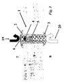
FIG. 1 shows a cross-sectional view of the device. -
FIG. 2 shows a cross-sectional view of the implanted device, designed to treat ascites, when the peritoneal pressure is sufficient to permit drainage. -
FIG. 3 shows a cross-sectional view of the implanted device, designed to treat ascites, when the peritoneal pressure is not sufficient to open the valve and no fluid flow occurs. -
FIG. 4 is an illustration of an example of an insertion device through which the current invention can be implanted in the bladder wall. -
FIG. 5 is an illustration of alternative embodiments of the invention with differing valve types, differing valve positioning and differing number of valves. -
FIG. 6 is an illustration of an alternative embodiment of the device in which an active, externally or internally controlled valve is utilized. -
FIG. 7 is an illustration of an alternative embodiment of the device in which a pump is included along the length of the tubing and placed subcutaneously for external control of drainage with a passive valve. -
FIG. 8 is an illustration of a few of the alternative embodiment of the device in which the peritoneal cavity, the pulmonary space and the ventricular space are able to be drained (pericardial drainage device not shown). - As can be seen in
FIG. 1 , the present invention provides a novelvesicular drain 1 for implantation in thebladder wall 9 which will provide for unidirectional drainage of fluid into the bladder. Thedrain 1 provides two flanges at itsends bladder wall 9. Alternative embodiments of the device may use other anchoring mechanisms, including, but not limited to: a screw thread on the outside of 1, staples, sutures, an adhesive compound, and/or one or more barbs. - The hollow shaft of the device contains a ball-
valve 4 through which a positive closing pressure is provided by an attachedspring 5. - The fluid collection interface of the
device 1 may optionally include alarge pore mesh 6 to allow for free flow of fluid while preventing incarceration of tissues at the drainage site. - As can be seen in
FIG. 2 , once the pressure of the fluid collection (in this case the peritoneal cavity) 7 exceeds the combined force of thespring 5 and the pressure of the fluid-filledbladder cavity 8, theperitoneal fluid 19 flows into thebladder cavity 8 through displacement of the ball-valve 4. There, the peritoneal fluid mixes with theurine 20. - If the pressure of the
bladder cavity 8 and the force of thespring 5, though, are greater than the pressure of the fluid collection (in this case the peritoneal cavity) 7, then thevalve 4 will remain closed preventing reflux ofurine 19 into the peritoneal cavity as depicted inFIG. 3 . - The device is designed to be placed transurethrally or transabdominally via an
insertion device 10 such as that depicted inFIG. 4 . The method of insertion allows for a single invasive procedure to provide a long-term solution to the otherwise difficult problem of refractory, chronic ascites. - Alternatively, the device may contain a length of
tubing 11 or other means of fluid transport to reach the fluid collection as well as an optionalperforated receptacle passive valves 4, 13 (flapper-valve), 14 (inFIG. 5 ), or active valves 15 (inFIG. 6 ) for tighter control of fluid drainage. - The device is also designed to be able to incorporate a
pump mechanism 16 inFIG. 7 which, when placed subcutaneously, can be actuated to provide an active pumping mechanism with thepassive valves active valve 15. A third embodiment of the invention involves a unidirectional pump in place of the valve, controlling the flow of fluid through the device. A fourth conception of the invention involves a single unidirectional valve controlling the flow of fluid through the device. - Alternatively, maneuvers which increase the pressure of the fluid cavity can also be utilized with the
passive valves - The device will be designed to drain a variety of different fluid collections including, but not limited to, the peritoneal cavity
FIG. 8A , pulmonary effusionsFIG. 8B and excessive cerebrospinal fluidFIG. 8C . Pericardial effusion drain is not shown. - Of particular interest to the inventors is the use of the invention to drain pulmonary effusions and other fluid collections in the lungs, in
FIG. 8B . - While these are the preferred embodiments, the device could employ any mechanism which provides a unidirectional passive or active valve for the drainage of any body fluid into the urinary bladder. This could involve filtration of the fluid through a polymer so as to sequester albumin and other proteins in the fluid collection while allowing flow of water and ions across the semi-permeable membrane. This could also involve an electronic valve triggered via communication across the tissues of the human body through EMFs such as radio, electricity, pressure, mechanical, magnetism, or other means of communication, allowing drainage only at selected times. The valve of the device can take many shapes and the device can be manufactured from any of a variety of materials with the only requirement being that of biocompatibility. Alternatively, the device, in either the active or passive embodiment, may incorporate anti-infective components in order to prevent the spread of infection between the body cavities. Such anti-infective components include, but are not limited to, bacteriostatic materials, bacteriocidal materials, one or more antibiotic dispensers, antibiotic eluting materials, entrained radioisotopes, a heating element, bioactive plastics, surfaces which encourage epithelialization, and coatings which prevent bacterial adhesion. Alternatively, the device, in either the active or passive embodiment, may incorporate anti-clogging components. Such anti-clogging components include, but are not limited to, an active ultrasonic component, an inner and outer sleeve which, when actively agitated, disrupt the inner lumen, surfaces which encourage epithelialization, enzyme eluting materials, enzyme eluting materials which specifically target the proteinaceous components of ascites, chemical eluting surfaces, an intermittent plunger mechanism, and coatings which prevent adhesion of proteinaceous compounds.
- While the device is primarily contemplated for use in human patients, the inventors also contemplate that the invention will have veterinary uses or product development purposes in equine, bovine, canine, feline, and other mammalian species.
- The claims of the parent application are reproduced below on pages 7-12. These clauses define preferred embodiments. The applicant reserves the right to pursue protection for the combinations of features set out in these clauses, and/or for any other subject-matter contained in the parent application as filed, either in the present divisional application or in a further application divided from the present divisional application. The claims of the parent application are not the claims of this divisional application. The claims of the current divisional application are contained in a separate section on pages numbered 13 and 14 and headed "Claims".
-
- 1. A vesicular shunt, comprising:
- a hollow cylinder, having an inside and an outside, and also having an inflow end and an outflow end;
- a valve, in continuous fluid communication with the inside of said hollow cylinder, wherein said valve regulates the flow of fluid within the hollow cylinder such that fluid may flow from the inflow end of said hollow cylinder to the outflow end of said hollow cylinder.
- 2. A vesicular shunt as recited in
clause 1, further comprising:- a first flange, located on the outside of said hollow cylinder near the first end; and
- a second flange, located on the outside of said hollow cylinder near the second end.
- 3. A vesicular shunt as recited in
clause 1, further comprising a mesh attached to the inflow end of said hollow cylinder. - 4. A vesicular shunt as recited in
clause 1, wherein said valve is a ball-valve. - 5. A vesicular shunt as recited in
clause 1, wherein said valve is a flapper-valve. - 6. A vesicular shunt as recited in
clause 1, wherein said valve is an active-valve. - 7. A vesicular shunt as recited in
clause 6, wherein said active-valve is controlled through a pressure signal. - 8. A vesicular shunt as recited in
clause 6, wherein said active-valve is controlled through a mechanical signal. - 9. A vesicular shunt as recited in
clause 6, wherein said active-valve is controlled through a magnetic signal. - 10. A vesicular shunt as recited in
clause 6, wherein said active-valve is controlled through an electric signal. - 11. A vesicular shunt as recited in
clause 6, wherein said active-valve is controlled through an EMF signal. - 12. A vesicular shunt as recited in
clause 11, wherein said EMF signal is a radio signal. - 13. A vesicular shunt, comprising:
- a hollow cylinder, having an inside and an outside, and also having an inflow end and an outflow end;
- a valve, located inside said hollow cylinder, wherein said valve regulates the flow of fluid within the hollow cylinder such that fluid may flow from the inflow end of said hollow cylinder to the outflow end of said hollow cylinder; and
- a flexible tube, having an inflow and an outflow end, the outflow end of said flexible tube being in fluid communication with the inflow end of said hollow cylinder.
- 14. A vesicular shunt as recited in
clause 13, further comprising:- a first flange, located on the outside of said hollow cylinder near the first end; and
- a second flange, located on the outside of said hollow cylinder near the second end.
- 15. A vesicular shunt as recited in
clause 13, wherein said valve is a ball-valve. - 16. A vesicular shunt as recited in
clause 13, wherein said valve is a flapper-valve. - 17. A vesicular shunt as recited in
clause 13, wherein said valve is an active-valve. - 18. A vesicular shunt as recited in
clause 17, wherein said active-valve is controlled through an electric signal. - 19. A vesicular shunt as recited in
clause 17, wherein said active-valve is controlled through a pressure signal. - 20. A vesicular shunt as recited in
clause 17, wherein said active-valve is controlled through a mechanical signal. - 21. A vesicular shunt as recited in
clause 17, wherein said active-valve is controlled through a magnetic signal. - 22. A vesicular shunt as recited in
clause 17, wherein said active-valve is controlled through an EMF signal. - 23. A vesicular shunt as recited in clause 22, wherein said EMF signal is a radio signal.
- 24. A vesicular shunt as recited in
clause 13, further comprising a mesh attached to the inflow end of said hollow cylinder. - 25. A vesicular shunt as recited in
clause 13, further comprising a perforated receptacle attached to the inflow end of said flexible tube. - 26. A vesicular shunt as recited in
clause 13, further comprising a valve located within the flexible tube near the inflow end of said flexible tube. - 27. A vesicular shunt as recited in
clause 13, further comprising a pump, attached to the flexible tube so that said pump is capable of moving fluid from the inflow end of said flexible tube to the outflow end. - 28. A vesicular shunt for draining bodily fluids, comprising:
- a tube, wherein said tube is designed to be implanted in the wall of the bladder;
- a means for anchoring said tube in the wall of the bladder; and
- a means for ensuring unidirectional flow through said tube.
- 29. A vesicular shunt as recited in clause 28, further comprising a means for preventing the passage of solids through said tube.
- 30. A vesicular shunt as recited in clause 28, wherein said means for anchoring is a pair of flanges.
- 31. A vesicular shunt as recited in clause 28, wherein said means for anchoring is a screw.
- 32. A vesicular shunt as recited in clause 28, wherein said means for anchoring is a suture.
- 33. A vesicular shunt as recited in clause 28, wherein said means for ensuring unidirectional flow is a valve.
- 34. A vesicular shunt as recited in clause 33, wherein said valve is a ball-valve.
- 35. A vesicular shunt as recited in clause 33, wherein said valve is a flapper-valve.
- 36. A vesicular shunt as recited in clause 33, wherein said valve is an active-valve.
- 37. A vesicular shunt as recited in clause 36, wherein said active-valve is controlled through an electric signal.
- 38. A vesicular shunt as recited in clause 36, wherein said active-valve is controlled through a pressure signal.
- 39. A vesicular shunt as recited in clause 36, wherein said active-valve is controlled through a mechanical signal.
- 40. A vesicular shunt as recited in clause 36, wherein said active-valve is controlled through a magnetic signal.
- 41. A vesicular shunt as recited in clause 36, wherein said active-valve is controlled through an EMF signal.
- 42. A vesicular shunt as recited in clause 41, wherein said EMF signal is a radio signal.
- 43. A vesicular shunt as recited in clause 28, further comprising a transport means for collecting fluid from remote interstices.
- 44. A vesicular shunt as recited in clause 33, further comprising a pump means for speeding the collection of fluid.
- 45. A vesicular shunt as recited in clause 33, further comprising a pump, wherein said pump is configured to transport fluid through the tube means for deposition in the bladder.
- 46. A vesicular shunt as recited in clause 33, wherein said tube means includes a valve located within said tube means.
- 47. A vesicular shunt as recited in clause 28, further comprising an anti-infective means.
- 48. A vesicular shunt as recited in clause 47, wherein said anti-infective means is a surface which encourages epithelialization.
- 49. A vesicular shunt as recited in clause 47, wherein said anti-infective means is a bacteriocidal material.
- 50. A vesicular shunt as recited in clause 47, wherein said anti-infective means is one or more antibiotic dispensers.
- 51. A vesicular shunt as recited in clause 47, wherein said anti-infective means is an entrained radioisotope.
- 52. A vesicular shunt as recited in clause 28, further comprising an anti-clogging means.
- 53. A vesicular shunt as recited in clause 51, wherein said anti-clogging means is an active ultrasound component.
- 54. A vesicular shunt as recited in clause 51, wherein said anti-clogging means is an inner and outer lumen.
- 55. A vesicular shunt as recited in clause 51, wherein said anti-clogging means is a surface which promotes epithelialization.
- 56. A vesicular shunt as recited in clause 51, wherein said anti-clogging means is an enzyme eluting material.
- 57. A method for draining excess fluid into the bladder of a living host, comprising:
- implanting the cylinder of the device of
clause 13 into the wall of the bladder; - implanting the inflow end of the tube of the device of
clause 13 into the region to be drained.
- implanting the cylinder of the device of
- 58. The method of clause 57, wherein the region to be drained is the pleural cavity.
- 59. The method of clause 57, wherein the region to be drained is the cerebrospinal cavity.
- 60. The method of clause 57, wherein the region to be drained is the peritoneal cavity.
- 61. The method of clause 57, wherein the host is a human.
- 62. The method of clause 57, wherein the host is a non-human mammal.
- 63. The method of clause 57, wherein the host is equine.
- 64. The method of clause 57, wherein the host is bovine.
- 65. The method of clause 57, wherein the host is feline.
- 66. The method of clause 57, wherein the host is canine.
Claims (15)
- A vesicular shunt for draining bodily fluids, comprising:a tube, wherein said tube is designed to be implanted in the wall of the bladder;a means for preventing the passage of solids through said tube;a means for anchoring said tube in the wall of the bladder; anda means for ensuring unidirectional flow through said tube.
- A vesicular shunt as claimed in claim 1, wherein said means for anchoring is a pair of flanges.
- A vesicular shunt as claimed in claim 1, wherein said means for anchoring is a screw.
- A vesicular shunt as claimed in claim 1, wherein said means for anchoring is a suture.
- A vesicular shunt as claimed in claim 1, wherein said means for ensuring unidirectional flow is a valve.
- A vesicular shunt as claimed in claim 1, further comprising a transport means for collecting fluid from remote interstices.
- A vesicular shunt as claimed in claim 5, further comprising a pump means for speeding the collection of fluid.
- A vesicular shunt as claimed in claim 5, further comprising a pump, wherein said pump is configured to transport fluid through the tube means for deposition in the bladder.
- A vesicular shunt as claimed in claim 5, wherein said tube means includes a valve located within said tube means.
- A vesicular shunt as claimed in claim 1, further comprising an anti-infective means, which means may be selected from a group comprising:a surface which encourages epithelialization;a bacteriocidal material;one or more antibiotic dispensers; andan entrained radioisotope.
- A vesicular shunt as claimed in claim 1, further comprising an anti-clogging means, which means may be selected from a group comprising:an active ultrasound component;an inner and outer lumen;a surface which promotes epithelialization; andan enzyme eluting material.
- A vesicular shunt as claimed in claim 5, wherein said valve is a ball-valve.
- A vesicular shunt as claimed in claim 5, wherein said valve is a flapper-valve.
- A vesicular shunt as claimed in claim 5, wherein said valve is an active-valve, which active-valve may be controlled through any one of an electric signal, a pressure signal, a mechanical signal, a magnetic signal and an EMF signal.
- A vesicular shunt as claimed in claim 14, wherein when said active-valve controlling signal is an EMF signal said EMF signal is a radio signal.
Applications Claiming Priority (3)
| Application Number | Priority Date | Filing Date | Title |
|---|---|---|---|
| US35928702P | 2002-02-25 | 2002-02-25 | |
| US38934602P | 2002-06-18 | 2002-06-18 | |
| EP03719316.6A EP1485146B1 (en) | 2002-02-25 | 2003-02-21 | Vesicular shunt for the drainage of excess fluid |
Related Parent Applications (2)
| Application Number | Title | Priority Date | Filing Date |
|---|---|---|---|
| EP03719316.6A Division EP1485146B1 (en) | 2002-02-25 | 2003-02-21 | Vesicular shunt for the drainage of excess fluid |
| EP03719316.6 Division | 2003-02-21 |
Publications (2)
| Publication Number | Publication Date |
|---|---|
| EP2374487A1 true EP2374487A1 (en) | 2011-10-12 |
| EP2374487B1 EP2374487B1 (en) | 2014-04-09 |
Family
ID=27767568
Family Applications (2)
| Application Number | Title | Priority Date | Filing Date |
|---|---|---|---|
| EP03719316.6A Expired - Lifetime EP1485146B1 (en) | 2002-02-25 | 2003-02-21 | Vesicular shunt for the drainage of excess fluid |
| EP11172759.0A Expired - Lifetime EP2374487B1 (en) | 2002-02-25 | 2003-02-21 | Vesicular shunt for the drainage of excess fluid |
Family Applications Before (1)
| Application Number | Title | Priority Date | Filing Date |
|---|---|---|---|
| EP03719316.6A Expired - Lifetime EP1485146B1 (en) | 2002-02-25 | 2003-02-21 | Vesicular shunt for the drainage of excess fluid |
Country Status (7)
| Country | Link |
|---|---|
| US (2) | US7335179B2 (en) |
| EP (2) | EP1485146B1 (en) |
| JP (1) | JP2006507018A (en) |
| AU (1) | AU2003223187B2 (en) |
| CA (1) | CA2477054C (en) |
| ES (2) | ES2461625T3 (en) |
| WO (1) | WO2003072166A1 (en) |
Families Citing this family (113)
| Publication number | Priority date | Publication date | Assignee | Title |
|---|---|---|---|---|
| US7311690B2 (en) | 2002-02-25 | 2007-12-25 | Novashunt Ag | Implantable fluid management system for the removal of excess fluid |
| AU2003223187B2 (en) | 2002-02-25 | 2008-05-22 | Sequana Medical Ag | Vesicular shunt for the drainage of excess fluid |
| US9694166B2 (en) | 2002-03-26 | 2017-07-04 | Medtronics Ps Medical, Inc. | Method of draining cerebrospinal fluid |
| US8886273B2 (en) | 2003-08-01 | 2014-11-11 | Dexcom, Inc. | Analyte sensor |
| US20190357827A1 (en) | 2003-08-01 | 2019-11-28 | Dexcom, Inc. | Analyte sensor |
| US7591801B2 (en) | 2004-02-26 | 2009-09-22 | Dexcom, Inc. | Integrated delivery device for continuous glucose sensor |
| US8626257B2 (en) | 2003-08-01 | 2014-01-07 | Dexcom, Inc. | Analyte sensor |
| US7920906B2 (en) | 2005-03-10 | 2011-04-05 | Dexcom, Inc. | System and methods for processing analyte sensor data for sensor calibration |
| US9247900B2 (en) | 2004-07-13 | 2016-02-02 | Dexcom, Inc. | Analyte sensor |
| US8774886B2 (en) * | 2006-10-04 | 2014-07-08 | Dexcom, Inc. | Analyte sensor |
| US8287453B2 (en) * | 2003-12-05 | 2012-10-16 | Dexcom, Inc. | Analyte sensor |
| US8425416B2 (en) | 2006-10-04 | 2013-04-23 | Dexcom, Inc. | Analyte sensor |
| US8423114B2 (en) | 2006-10-04 | 2013-04-16 | Dexcom, Inc. | Dual electrode system for a continuous analyte sensor |
| US8364231B2 (en) | 2006-10-04 | 2013-01-29 | Dexcom, Inc. | Analyte sensor |
| US20080197024A1 (en) * | 2003-12-05 | 2008-08-21 | Dexcom, Inc. | Analyte sensor |
| US11633133B2 (en) | 2003-12-05 | 2023-04-25 | Dexcom, Inc. | Dual electrode system for a continuous analyte sensor |
| US8364230B2 (en) | 2006-10-04 | 2013-01-29 | Dexcom, Inc. | Analyte sensor |
| US8425417B2 (en) * | 2003-12-05 | 2013-04-23 | Dexcom, Inc. | Integrated device for continuous in vivo analyte detection and simultaneous control of an infusion device |
| US8808228B2 (en) | 2004-02-26 | 2014-08-19 | Dexcom, Inc. | Integrated medicament delivery device for use with continuous analyte sensor |
| US7351198B2 (en) * | 2004-06-02 | 2008-04-01 | Ethicon Endo-Surgery, Inc. | Implantable adjustable sphincter system |
| FR2871386B1 (en) * | 2004-06-11 | 2006-09-22 | Sophysa Sa | SUBCUTANEOUS VALVE |
| US7640048B2 (en) | 2004-07-13 | 2009-12-29 | Dexcom, Inc. | Analyte sensor |
| US20060020192A1 (en) | 2004-07-13 | 2006-01-26 | Dexcom, Inc. | Transcutaneous analyte sensor |
| US7783333B2 (en) | 2004-07-13 | 2010-08-24 | Dexcom, Inc. | Transcutaneous medical device with variable stiffness |
| US8202248B2 (en) | 2004-08-18 | 2012-06-19 | Sequana Medical Ag | Dialysis implant and methods of use |
| US20060095021A1 (en) * | 2004-11-02 | 2006-05-04 | Casas-Bejar Jesus W | Introduction of agent with medical device |
| FR2877579B1 (en) * | 2004-11-09 | 2007-01-19 | Jose Bensoussan | DEVICE FOR ASPIRATING NASAL SECRETIONS |
| US7775966B2 (en) | 2005-02-24 | 2010-08-17 | Ethicon Endo-Surgery, Inc. | Non-invasive pressure measurement in a fluid adjustable restrictive device |
| US7658196B2 (en) | 2005-02-24 | 2010-02-09 | Ethicon Endo-Surgery, Inc. | System and method for determining implanted device orientation |
| US8016744B2 (en) | 2005-02-24 | 2011-09-13 | Ethicon Endo-Surgery, Inc. | External pressure-based gastric band adjustment system and method |
| US7927270B2 (en) | 2005-02-24 | 2011-04-19 | Ethicon Endo-Surgery, Inc. | External mechanical pressure sensor for gastric band pressure measurements |
| US7699770B2 (en) | 2005-02-24 | 2010-04-20 | Ethicon Endo-Surgery, Inc. | Device for non-invasive measurement of fluid pressure in an adjustable restriction device |
| US8066629B2 (en) | 2005-02-24 | 2011-11-29 | Ethicon Endo-Surgery, Inc. | Apparatus for adjustment and sensing of gastric band pressure |
| US7775215B2 (en) | 2005-02-24 | 2010-08-17 | Ethicon Endo-Surgery, Inc. | System and method for determining implanted device positioning and obtaining pressure data |
| US20060235349A1 (en) * | 2005-04-14 | 2006-10-19 | Brett Osborn | Implantable anti-clogging device for maintenance of cerebrospinal fluid shunt patency |
| US8002730B2 (en) * | 2005-04-29 | 2011-08-23 | Medtronic, Inc. | Anti-thrombogenic venous shunt system and method |
| US8328792B2 (en) | 2005-10-27 | 2012-12-11 | C. R. Bard, Inc. | Enhanced pre-wetted intermittent catheter with lubricious coating |
| US8870742B2 (en) | 2006-04-06 | 2014-10-28 | Ethicon Endo-Surgery, Inc. | GUI for an implantable restriction device and a data logger |
| US8152710B2 (en) | 2006-04-06 | 2012-04-10 | Ethicon Endo-Surgery, Inc. | Physiological parameter analysis for an implantable restriction device and a data logger |
| US8275438B2 (en) * | 2006-10-04 | 2012-09-25 | Dexcom, Inc. | Analyte sensor |
| US8449464B2 (en) * | 2006-10-04 | 2013-05-28 | Dexcom, Inc. | Analyte sensor |
| US8298142B2 (en) * | 2006-10-04 | 2012-10-30 | Dexcom, Inc. | Analyte sensor |
| US8562528B2 (en) * | 2006-10-04 | 2013-10-22 | Dexcom, Inc. | Analyte sensor |
| US8478377B2 (en) * | 2006-10-04 | 2013-07-02 | Dexcom, Inc. | Analyte sensor |
| US8447376B2 (en) | 2006-10-04 | 2013-05-21 | Dexcom, Inc. | Analyte sensor |
| JP5414528B2 (en) | 2006-10-31 | 2014-02-12 | セクアナ メディカル エージー | Implantable fluid management device for removing excess fluid |
| EP2152350A4 (en) * | 2007-06-08 | 2013-03-27 | Dexcom Inc | Integrated medicament delivery device for use with continuous analyte sensor |
| US8366652B2 (en) * | 2007-08-17 | 2013-02-05 | The Invention Science Fund I, Llc | Systems, devices, and methods including infection-fighting and monitoring shunts |
| EP4098177A1 (en) | 2007-10-09 | 2022-12-07 | DexCom, Inc. | Integrated insulin delivery system with continuous glucose sensor |
| US20090143713A1 (en) | 2007-11-30 | 2009-06-04 | Jacques Van Dam | Biliary Shunts, Delivery Systems, Methods of Using the Same and Kits Therefor |
| US8187163B2 (en) | 2007-12-10 | 2012-05-29 | Ethicon Endo-Surgery, Inc. | Methods for implanting a gastric restriction device |
| US8100870B2 (en) | 2007-12-14 | 2012-01-24 | Ethicon Endo-Surgery, Inc. | Adjustable height gastric restriction devices and methods |
| US8377079B2 (en) | 2007-12-27 | 2013-02-19 | Ethicon Endo-Surgery, Inc. | Constant force mechanisms for regulating restriction devices |
| US8142452B2 (en) | 2007-12-27 | 2012-03-27 | Ethicon Endo-Surgery, Inc. | Controlling pressure in adjustable restriction devices |
| US8591395B2 (en) | 2008-01-28 | 2013-11-26 | Ethicon Endo-Surgery, Inc. | Gastric restriction device data handling devices and methods |
| WO2009096854A1 (en) * | 2008-01-28 | 2009-08-06 | Milux Holding Sa | An implantable fluid movement device |
| EP4088772A1 (en) * | 2008-01-28 | 2022-11-16 | Implantica Patent Ltd. | A drainage device |
| US8192350B2 (en) | 2008-01-28 | 2012-06-05 | Ethicon Endo-Surgery, Inc. | Methods and devices for measuring impedance in a gastric restriction system |
| US8337389B2 (en) | 2008-01-28 | 2012-12-25 | Ethicon Endo-Surgery, Inc. | Methods and devices for diagnosing performance of a gastric restriction system |
| US7844342B2 (en) | 2008-02-07 | 2010-11-30 | Ethicon Endo-Surgery, Inc. | Powering implantable restriction systems using light |
| US8221439B2 (en) | 2008-02-07 | 2012-07-17 | Ethicon Endo-Surgery, Inc. | Powering implantable restriction systems using kinetic motion |
| US8114345B2 (en) | 2008-02-08 | 2012-02-14 | Ethicon Endo-Surgery, Inc. | System and method of sterilizing an implantable medical device |
| US8591532B2 (en) | 2008-02-12 | 2013-11-26 | Ethicon Endo-Sugery, Inc. | Automatically adjusting band system |
| US8057492B2 (en) | 2008-02-12 | 2011-11-15 | Ethicon Endo-Surgery, Inc. | Automatically adjusting band system with MEMS pump |
| US20090209995A1 (en) * | 2008-02-14 | 2009-08-20 | Byrum Randal T | Implantable adjustable sphincter system |
| US8034065B2 (en) | 2008-02-26 | 2011-10-11 | Ethicon Endo-Surgery, Inc. | Controlling pressure in adjustable restriction devices |
| US8233995B2 (en) | 2008-03-06 | 2012-07-31 | Ethicon Endo-Surgery, Inc. | System and method of aligning an implantable antenna |
| US8187162B2 (en) | 2008-03-06 | 2012-05-29 | Ethicon Endo-Surgery, Inc. | Reorientation port |
| US8396528B2 (en) | 2008-03-25 | 2013-03-12 | Dexcom, Inc. | Analyte sensor |
| US8211053B2 (en) | 2008-05-13 | 2012-07-03 | Equilibrate, Llc | Interosmolar fluid removal |
| US20120041285A1 (en) | 2008-12-04 | 2012-02-16 | Searete Llc, A Limited Liability Corporation Of The State Of Delaware | Systems, devices, and methods including implantable devices with anti-microbial properties |
| US9901347B2 (en) * | 2009-05-29 | 2018-02-27 | Terus Medical, Inc. | Biliary shunts, delivery systems, and methods of using the same |
| US10149961B2 (en) | 2009-07-29 | 2018-12-11 | C. R. Bard, Inc. | Catheter having improved drainage and/or a retractable sleeve and method of using the same |
| US9821139B2 (en) | 2009-08-13 | 2017-11-21 | C. R. Bard, Inc. | Catheter having internal hydrating fluid storage and/or catheter package using the same and method of making and/or using the same |
| US9375223B2 (en) | 2009-10-06 | 2016-06-28 | Cardioprolific Inc. | Methods and devices for endovascular therapy |
| ES2655824T3 (en) | 2009-12-23 | 2018-02-21 | C. R. Bard, Inc. | Catheter package / unit using a hydrating / hydrogel sleeve |
| DE102009060533B4 (en) * | 2009-12-23 | 2019-07-11 | Christoph Miethke Gmbh & Co Kg | Implantable shunt system |
| US9033149B2 (en) | 2010-03-04 | 2015-05-19 | C. R. Bard, Inc. | Catheter assembly/package utilizing a hydrating/hydrogel sleeve and a foil outer layer and method of making and using the same |
| EP3552654B1 (en) * | 2011-02-16 | 2023-06-21 | Sequana Medical NV | Apparatus for treating intracorporeal fluid accumulation |
| US9675327B2 (en) | 2011-02-16 | 2017-06-13 | Sequana Medical Ag | Apparatus and methods for noninvasive monitoring of cancerous cells |
| WO2012111137A1 (en) * | 2011-02-18 | 2012-08-23 | 株式会社パイオラックスメディカルデバイス | Stent for abdominal cavity-vein shunt |
| WO2012142502A2 (en) | 2011-04-15 | 2012-10-18 | Dexcom Inc. | Advanced analyte sensor calibration and error detection |
| US8771220B2 (en) * | 2011-12-07 | 2014-07-08 | Alcon Research, Ltd. | Glaucoma active pressure regulation shunt |
| US8585635B2 (en) | 2012-02-15 | 2013-11-19 | Sequana Medical Ag | Systems and methods for treating chronic liver failure based on peritoneal dialysis |
| US20140012180A1 (en) * | 2012-05-01 | 2014-01-09 | Nidus Medical, Llc | Peritoneal drain and infusion |
| US9339636B1 (en) | 2012-09-06 | 2016-05-17 | Mubashir H Khan | Subcutaneous fluid pump |
| USD743542S1 (en) | 2012-10-31 | 2015-11-17 | Sequana Medical Ag | Catheter with staggered slits |
| USD743543S1 (en) | 2012-10-31 | 2015-11-17 | Sequana Medical Ag | Catheter with staggered slits |
| US9144660B2 (en) | 2012-10-31 | 2015-09-29 | Sequana Medical Ag | Implantable catheters with staggered slits, and methods of using same |
| US9126009B2 (en) | 2013-03-12 | 2015-09-08 | DePuy Synthes Products, Inc. | System and method for determining position and pressure of an implantable shunt |
| US8998882B2 (en) | 2013-03-13 | 2015-04-07 | C. R. Bard, Inc. | Enhanced pre-wetted intermittent catheter with lubricious coating |
| US9577459B2 (en) | 2013-03-15 | 2017-02-21 | Sequana Medical Ag | Systems and methods for regulating inductive energy transfer to an implantable system |
| US9421348B2 (en) | 2013-10-01 | 2016-08-23 | Ecole Polytechnique Federale De Lausanne (Epfl) | Systems and methods for moving and circulating fluid to treat alzheimer's disease |
| WO2016090378A1 (en) * | 2014-12-05 | 2016-06-09 | The Johns Hopkins University | Implantable body-driven shunt pump |
| US10716922B2 (en) | 2016-08-26 | 2020-07-21 | Sequana Medical Nv | Implantable fluid management system having clog resistant catheters, and methods of using same |
| JP7071338B2 (en) | 2016-08-26 | 2022-05-18 | セクアナ メディカル エヌブイ | Systems and methods for managing and analyzing data generated by embedded devices |
| EP3612246B1 (en) | 2017-05-24 | 2020-12-30 | Sequana Medical NV | Direct sodium removal method, solution and apparatus to reduce fluid overload in heart failure patients |
| US11559618B2 (en) | 2017-05-24 | 2023-01-24 | Sequana Medical Nv | Formulations and methods for direct sodium removal in patients having severe renal dysfunction |
| CA3070108A1 (en) | 2017-07-20 | 2019-01-24 | Shifamed Holdings, Llc | Adjustable flow glaucoma shunts and methods for making and using same |
| US11166849B2 (en) | 2017-07-20 | 2021-11-09 | Shifamed Holdings, Llc | Adjustable flow glaucoma shunts and methods for making and using same |
| EP3681449A1 (en) * | 2017-09-11 | 2020-07-22 | Oregon Health & Science University | Glaucoma tube implant with modulated flow |
| US11382540B2 (en) | 2017-10-24 | 2022-07-12 | Dexcom, Inc. | Pre-connected analyte sensors |
| US11331022B2 (en) | 2017-10-24 | 2022-05-17 | Dexcom, Inc. | Pre-connected analyte sensors |
| JP2022552284A (en) | 2019-10-10 | 2022-12-15 | シファメド・ホールディングス・エルエルシー | Adjustable flow glaucoma shunt and related systems and methods |
| JP2023511420A (en) | 2020-01-23 | 2023-03-17 | シファメド・ホールディングス・エルエルシー | Adjustable-flow glaucoma shunts and related systems and methods |
| EP4103117A4 (en) | 2020-02-14 | 2024-03-20 | Shifamed Holdings Llc | Shunting systems with rotation-based flow control assemblies, and associated systems and methods |
| WO2021168130A1 (en) | 2020-02-18 | 2021-08-26 | Shifamed Holdings, Llc | Adjustable flow glaucoma shunts having non-linearly arranged flow control elements, and associated systems and methods |
| US11766355B2 (en) | 2020-03-19 | 2023-09-26 | Shifamed Holdings, Llc | Intraocular shunts with low-profile actuation elements and associated systems and methods |
| US20210322737A1 (en) * | 2020-04-14 | 2021-10-21 | The Regents Of The University Of California | Compositions and methods for reducing traumatic edema from severe spinal cord injury |
| JP2023522332A (en) | 2020-04-16 | 2023-05-30 | シファメド・ホールディングス・エルエルシー | ADJUSTABLE GLAUCOMA TREATMENT DEVICES AND RELATED SYSTEMS AND METHODS |
| WO2022065058A1 (en) * | 2020-09-23 | 2022-03-31 | 浩通 伊佐山 | Liquid recirculation device |
| CN112879273A (en) * | 2021-01-05 | 2021-06-01 | 浙江清华柔性电子技术研究院 | Implantable body fluid transport pump and pump system for directional transport of body fluid |
| EP4281144A1 (en) | 2021-01-22 | 2023-11-29 | Shifamed Holdings, LLC | Adjustable shunting systems with plate assemblies, and associated systems and methods |
Citations (3)
| Publication number | Priority date | Publication date | Assignee | Title |
|---|---|---|---|---|
| US3654932A (en) * | 1969-11-26 | 1972-04-11 | John B Newkirk | Surgical drain for shunting fluid |
| US4657530A (en) * | 1984-04-09 | 1987-04-14 | Henry Buchwald | Compression pump-catheter |
| GB2350794A (en) * | 1999-04-20 | 2000-12-13 | Nagy Adly Habib | Implantable pump |
Family Cites Families (95)
| Publication number | Priority date | Publication date | Assignee | Title |
|---|---|---|---|---|
| US3540451A (en) * | 1967-02-28 | 1970-11-17 | William V Zeman | Drainage cannula with tissue connecting assemblies on both ends |
| US3516410A (en) | 1968-01-03 | 1970-06-23 | Salomon Hakim | Cerebro-ventricular catheter |
| US3608088A (en) | 1969-04-17 | 1971-09-28 | Univ Minnesota | Implantable blood pump |
| US3575158A (en) | 1969-07-18 | 1971-04-20 | Fairchild Hiller Corp | Method of controlling urine flow from the bladder with an inplantable pump |
| US3642004A (en) * | 1970-01-05 | 1972-02-15 | Life Support Equipment Corp | Urethral valve |
| US3626950A (en) | 1970-06-19 | 1971-12-14 | Heyer Schulte Corp | Catheter with augmented drainage means |
| US3810259A (en) | 1971-01-25 | 1974-05-14 | Fairchild Industries | Implantable urinary control apparatus |
| US3910283A (en) * | 1973-10-09 | 1975-10-07 | Harry H Leveen | Process for treatment of ascites and device to accomplish same |
| US4083786A (en) * | 1975-03-20 | 1978-04-11 | Asahi Kasei Kogyo Kabushiki Kaisha | Apparatus for treating ascites |
| US4261341A (en) * | 1979-06-08 | 1981-04-14 | Hakim Company Limited | Method and apparatus for the treatment of ascites |
| US4368737A (en) * | 1980-07-07 | 1983-01-18 | Purdue Research Foundation | Implantable catheter |
| US4418693A (en) * | 1980-12-10 | 1983-12-06 | Leveen Eric G | Vein and tubing passer surgical instrument |
| US4557724A (en) * | 1981-02-17 | 1985-12-10 | University Of Utah Research Foundation | Apparatus and methods for minimizing cellular adhesion on peritoneal injection catheters |
| US4416657A (en) * | 1982-08-13 | 1983-11-22 | Berglund Rickey T | Abdominal catheter implant |
| US4615691A (en) | 1983-12-08 | 1986-10-07 | Salomon Hakim | Surgically-implantable stepping motor |
| US4595390A (en) | 1983-07-21 | 1986-06-17 | Salomon Hakim | Magnetically-adjustable cerebrospinal fluid shunt valve |
| DE3333362C2 (en) | 1983-09-15 | 1986-03-20 | Fresenius AG, 6380 Bad Homburg | Peritoneal dialysis machine |
| US4584994A (en) | 1983-09-30 | 1986-04-29 | Charles Bamberger | Electromagnetic implant |
| US4610658A (en) * | 1985-02-21 | 1986-09-09 | Henry Buchwald | Automated peritoneovenous shunt |
| US4725207A (en) | 1985-02-21 | 1988-02-16 | Regents Of The University Of Minnesota | Automated peritoneovenous shunt |
| US4610625A (en) | 1985-09-23 | 1986-09-09 | Bunn Richard L | Burner |
| US4850955A (en) | 1986-12-02 | 1989-07-25 | Codman & Shurtleff | Body fluid transfer device |
| US4904236A (en) * | 1987-01-30 | 1990-02-27 | Vir Engineering | Fluid flow control valve |
| US4779614A (en) | 1987-04-09 | 1988-10-25 | Nimbus Medical, Inc. | Magnetically suspended rotor axial flow blood pump |
| US5356386A (en) | 1987-06-05 | 1994-10-18 | Uresil Corporation | Apparatus for locating body cavities |
| US4950232A (en) | 1987-08-11 | 1990-08-21 | Surelab Superior Research Laboratories | Cerebrospinal fluid shunt system |
| DE3831652A1 (en) * | 1988-09-17 | 1990-03-22 | Ruesch Willy Ag | ARRANGEMENT FOR DRAINING BODY CAVES |
| US5071408A (en) | 1988-10-07 | 1991-12-10 | Ahmed Abdul Mateen | Medical valve |
| GB8824855D0 (en) * | 1988-10-24 | 1988-11-30 | Byrne P O | Dialysis |
| US5021048A (en) | 1989-08-04 | 1991-06-04 | Medtronic, Inc. | Blood pump drive system |
| US5078688A (en) * | 1989-09-22 | 1992-01-07 | Baxter International Inc. | Paracentesis catheter system |
| US4991594A (en) * | 1989-11-20 | 1991-02-12 | Angelchik Jean P | Method and apparatus for removing ascitic fluid from abdominal cavity |
| US5147281A (en) | 1990-04-23 | 1992-09-15 | Advanced Medical Systems, Inc. | Biological fluid pumping means and method |
| US5167615A (en) | 1990-05-15 | 1992-12-01 | Pudenz-Schulte Medical Research Corporation | Flow control device having selectable alternative fluid pathways |
| US5830172A (en) * | 1991-04-11 | 1998-11-03 | Leveen; Harry H. | Ascites valve |
| US5520632A (en) * | 1991-04-11 | 1996-05-28 | Robert Leveen | Ascites valve |
| US6007511A (en) | 1991-05-08 | 1999-12-28 | Prywes; Arnold S. | Shunt valve and therapeutic delivery system for treatment of glaucoma and methods and apparatus for its installation |
| US5385541A (en) * | 1992-04-24 | 1995-01-31 | Loma Linda University Medical Center | Cerebrospinal fluid shunt capable of minimal invasive revision |
| US5431637A (en) | 1992-07-31 | 1995-07-11 | Sherwood Medical Company | Endotracheal suction catheter |
| US5397354A (en) * | 1992-08-19 | 1995-03-14 | Wilk; Peter J. | Method and device for removing a toxic substance from blood |
| US5360414A (en) | 1992-10-08 | 1994-11-01 | Yarger Richard J | Tube for draining body cavities, viscera and wounds |
| DE69311525T2 (en) | 1993-01-07 | 1997-10-02 | Tdk Corp | Electromagnetic pump with movable magnetic piston |
| US5474683A (en) | 1993-03-03 | 1995-12-12 | Deka Products Limited Partnership | Peritoneal dialysis systems and methods employing pneumatic pressure and temperature-corrected liquid volume measurements |
| US5254084A (en) * | 1993-03-26 | 1993-10-19 | Geary Gregory L | Peritoneal catheter device for dialysis |
| US5387188A (en) | 1993-05-10 | 1995-02-07 | Pudenz-Schulte Medical Research Corporation | Pulsatile flow-accommodating fluid shunt |
| US5395350A (en) * | 1994-02-14 | 1995-03-07 | Summers; Daniel A. | Paracentesis valve |
| US5762599A (en) | 1994-05-02 | 1998-06-09 | Influence Medical Technologies, Ltd. | Magnetically-coupled implantable medical devices |
| US5489276A (en) | 1994-10-07 | 1996-02-06 | Kormed, Inc. | Vacuum tube tip construction |
| US5624374A (en) * | 1994-11-03 | 1997-04-29 | Von Iderstein; Irwin F. | Involuntary urine control apparatus, system and method |
| US5575770A (en) | 1995-04-05 | 1996-11-19 | Therex Corporation | Implantable drug infusion system with safe bolus capability |
| US6558686B1 (en) * | 1995-11-08 | 2003-05-06 | Baylor College Of Medicine | Method of coating medical devices with a combination of antiseptics and antiseptic coating therefor |
| US5725506A (en) * | 1996-01-05 | 1998-03-10 | Denver Biomaterials, Inc. | Device for paracentesis and thoracentesis |
| US5637083A (en) | 1996-01-19 | 1997-06-10 | Pudenz-Schulte Medical Research Corporation | Implantable adjustable fluid flow control valve |
| CA2226170A1 (en) | 1996-05-05 | 1997-11-13 | Influence Medical Technologies Ltd. | Implantable pump and prosthetic devices |
| US5980480A (en) | 1996-07-11 | 1999-11-09 | Cs Fluids, Inc. | Method and apparatus for treating adult-onset dementia of the alzheimer's type |
| US6689085B1 (en) | 1996-07-11 | 2004-02-10 | Eunoe, Inc. | Method and apparatus for treating adult-onset dementia of the Alzheimer's type |
| IT1288975B1 (en) | 1996-08-16 | 1998-09-25 | Valter Paderni | SYSTEM FOR THE EXTRACTION OF FLUIDS |
| DE19643782C1 (en) * | 1996-09-09 | 1998-08-27 | Steffen Dr Ing Leonhardt | Implant for controlled drainage of brain fluid esp for treating hydrocephalus condition |
| US5902336A (en) | 1996-10-15 | 1999-05-11 | Mirimedical, Inc. | Implantable device and method for removing fluids from the blood of a patient method for implanting such a device and method for treating a patient experiencing renal failure |
| US5947911A (en) | 1997-01-09 | 1999-09-07 | Via Medical Corporation | Method and apparatus for reducing purge volume in a blood chemistry monitoring system |
| US6193684B1 (en) | 1997-01-21 | 2001-02-27 | Vasca, Inc. | Device for percutaneous peritoneal dialysis |
| US20010016699A1 (en) | 1997-02-14 | 2001-08-23 | Jeffrey H. Burbank | Hemofiltration system |
| US6022333A (en) | 1997-05-01 | 2000-02-08 | S.L.I.M. Tech, Ltd. | Method and system for removing materials from lymphatic and other fluids |
| DE69821936T2 (en) * | 1997-06-25 | 2004-12-16 | Biotap A/S | TRANSCUTANEOUS IMPLANT DEVICE |
| US5980478A (en) | 1997-10-10 | 1999-11-09 | Transvivo, Inc. | Apparatus and method for the treatment of acute and chronic renal disease by continuous passive plasma ultrafiltration |
| US5989207A (en) * | 1997-11-03 | 1999-11-23 | Hughes; Boyd R. | Double swirl stent |
| US6682500B2 (en) | 1998-01-29 | 2004-01-27 | David Soltanpour | Synthetic muscle based diaphragm pump apparatuses |
| US6295990B1 (en) | 1998-02-03 | 2001-10-02 | Salient Interventional Systems, Inc. | Methods and systems for treating ischemia |
| USD420738S (en) * | 1998-09-22 | 2000-02-15 | Chek Med Systems, Inc. | Paracentesis pump |
| US6875192B1 (en) | 1998-11-10 | 2005-04-05 | Eunoe, Inc. | Devices and methods for removing cerebrospinal fluids from a patient's CSF space |
| US6132415A (en) | 1999-02-09 | 2000-10-17 | Vasca, Inc. | Systems and methods for removing retained fluids and infusing therapeutic fluids |
| US6162238A (en) | 1999-02-24 | 2000-12-19 | Aaron V. Kaplan | Apparatus and methods for control of body lumens |
| US6254567B1 (en) | 1999-02-26 | 2001-07-03 | Nxstage Medical, Inc. | Flow-through peritoneal dialysis systems and methods with on-line dialysis solution regeneration |
| WO2000054826A1 (en) | 1999-03-17 | 2000-09-21 | Medtronic, Inc. | Tool for adjusting an implantable adjustable fluid flow control valve |
| SE514428C2 (en) | 1999-06-23 | 2001-02-19 | Anagram Consultants Ag | Implantable device for harnessing the hydraulic energy of the heart |
| US6533733B1 (en) * | 1999-09-24 | 2003-03-18 | Ut-Battelle, Llc | Implantable device for in-vivo intracranial and cerebrospinal fluid pressure monitoring |
| US6738661B1 (en) | 1999-10-22 | 2004-05-18 | Biosynergetics, Inc. | Apparatus and methods for the controllable modification of compound concentration in a tube |
| US6648906B2 (en) * | 2000-04-06 | 2003-11-18 | Innercool Therapies, Inc. | Method and apparatus for regulating patient temperature by irrigating the bladder with a fluid |
| US6887214B1 (en) | 2000-09-12 | 2005-05-03 | Chf Solutions, Inc. | Blood pump having a disposable blood passage cartridge with integrated pressure sensors |
| ES2309089T3 (en) | 2000-09-11 | 2008-12-16 | Csf Dynamics A/S | FLUID DERIVATION SYSTEM FOR THE TREATMENT OF HYDROCEPHALIA. |
| US6913590B2 (en) | 2000-09-22 | 2005-07-05 | Sorenson Development, Inc. | Apparatus and method for peritoneal dialysis |
| US6656227B2 (en) | 2000-10-20 | 2003-12-02 | John M. Levin | Prosthesis for internal peritoneal dialysis and method of providing peritoneal dialysis |
| EP1343557B1 (en) | 2000-12-11 | 2004-09-22 | Christoph Miethke Gmbh & Co. KG | Hydrocephalus valve |
| US20020073545A1 (en) * | 2000-12-19 | 2002-06-20 | Adc Telecommunications, Inc. | Enhanced heat transfer for housings |
| US7025739B2 (en) | 2001-08-09 | 2006-04-11 | Integra Lifesciences Corporation | System and method for treating elevated intracranial pressure |
| US6894456B2 (en) | 2001-11-07 | 2005-05-17 | Quallion Llc | Implantable medical power module |
| US6641378B2 (en) | 2001-11-13 | 2003-11-04 | William D. Davis | Pump with electrodynamically supported impeller |
| US7198611B2 (en) | 2002-02-11 | 2007-04-03 | Baxter International Inc. | Dialysis connector and cap having an integral disinfectant |
| US7311690B2 (en) | 2002-02-25 | 2007-12-25 | Novashunt Ag | Implantable fluid management system for the removal of excess fluid |
| AU2003223187B2 (en) | 2002-02-25 | 2008-05-22 | Sequana Medical Ag | Vesicular shunt for the drainage of excess fluid |
| EP1539798B1 (en) * | 2002-09-06 | 2010-11-24 | Genentech, Inc. | Process for protein extraction |
| US7252659B2 (en) | 2003-02-07 | 2007-08-07 | Alfred E. Mann Institute For Biomedical Engineering At The University Of Southern California | Implanted surgical drain with sensing and transmitting elements for monitoring internal tissue condition |
| US7128735B2 (en) | 2004-01-02 | 2006-10-31 | Richard Scott Weston | Reduced pressure wound treatment appliance |
| US8202248B2 (en) | 2004-08-18 | 2012-06-19 | Sequana Medical Ag | Dialysis implant and methods of use |
| JP4654000B2 (en) * | 2004-10-26 | 2011-03-16 | 京セラ株式会社 | Information processing system, IC tag, and IC tag reading method |
-
2003
- 2003-02-21 AU AU2003223187A patent/AU2003223187B2/en not_active Expired
- 2003-02-21 ES ES11172759.0T patent/ES2461625T3/en not_active Expired - Lifetime
- 2003-02-21 ES ES03719316T patent/ES2428965T3/en not_active Expired - Lifetime
- 2003-02-21 US US10/369,550 patent/US7335179B2/en active Active
- 2003-02-21 EP EP03719316.6A patent/EP1485146B1/en not_active Expired - Lifetime
- 2003-02-21 WO PCT/US2003/005145 patent/WO2003072166A1/en active Application Filing
- 2003-02-21 JP JP2003570909A patent/JP2006507018A/en not_active Withdrawn
- 2003-02-21 EP EP11172759.0A patent/EP2374487B1/en not_active Expired - Lifetime
- 2003-02-21 CA CA2477054A patent/CA2477054C/en not_active Expired - Lifetime
-
2008
- 2008-01-15 US US12/014,696 patent/US8394048B2/en not_active Expired - Lifetime
Patent Citations (3)
| Publication number | Priority date | Publication date | Assignee | Title |
|---|---|---|---|---|
| US3654932A (en) * | 1969-11-26 | 1972-04-11 | John B Newkirk | Surgical drain for shunting fluid |
| US4657530A (en) * | 1984-04-09 | 1987-04-14 | Henry Buchwald | Compression pump-catheter |
| GB2350794A (en) * | 1999-04-20 | 2000-12-13 | Nagy Adly Habib | Implantable pump |
Non-Patent Citations (1)
| Title |
|---|
| ROZENBLIT G N ET AL: "Peritoneal-Urinary Drainage for Treatment of Refractory Ascites: A Pilot Study", JOURNAL OF VASCULAR AND INTERVENTIONAL RADIOLOGY, VA LNKD- DOI:10.1016/S1051-0443(98)70440-3, vol. 9, no. 6, 1 November 1998 (1998-11-01), pages 998 - 1005, XP026146492, ISSN: 1051-0443, [retrieved on 19981101] * |
Also Published As
| Publication number | Publication date |
|---|---|
| CA2477054A1 (en) | 2003-09-04 |
| AU2003223187B2 (en) | 2008-05-22 |
| EP1485146A1 (en) | 2004-12-15 |
| EP1485146A4 (en) | 2010-07-07 |
| WO2003072166A1 (en) | 2003-09-04 |
| US7335179B2 (en) | 2008-02-26 |
| ES2461625T3 (en) | 2014-05-20 |
| CA2477054C (en) | 2011-05-31 |
| EP1485146B1 (en) | 2013-08-07 |
| AU2003223187A1 (en) | 2003-09-09 |
| EP2374487B1 (en) | 2014-04-09 |
| ES2428965T3 (en) | 2013-11-12 |
| US20030163079A1 (en) | 2003-08-28 |
| US20080154173A1 (en) | 2008-06-26 |
| JP2006507018A (en) | 2006-03-02 |
| US8394048B2 (en) | 2013-03-12 |
Similar Documents
| Publication | Publication Date | Title |
|---|---|---|
| US7335179B2 (en) | Vesicular shunt for the drainage of excess fluid | |
| US9913968B2 (en) | Implantable fluid management system for the removal of excess fluid | |
| US7025742B2 (en) | Internally powered CSF pump systems and methods | |
| US6264625B1 (en) | Method and apparatus for treating adult-onset dementia of the Alzheimer's type | |
| US6132415A (en) | Systems and methods for removing retained fluids and infusing therapeutic fluids | |
| US20140012180A1 (en) | Peritoneal drain and infusion | |
| US5098411A (en) | Closed end hollow stylet assembly | |
| US20240091511A1 (en) | Implantable Shunt System and Method | |
| CN114072184A (en) | Pump assembly and system for inducing negative pressure in a portion of a patient's urinary tract |
Legal Events
| Date | Code | Title | Description |
|---|---|---|---|
| PUAI | Public reference made under article 153(3) epc to a published international application that has entered the european phase |
Free format text: ORIGINAL CODE: 0009012 |
|
| AC | Divisional application: reference to earlier application |
Ref document number: 1485146 Country of ref document: EP Kind code of ref document: P |
|
| AK | Designated contracting states |
Kind code of ref document: A1 Designated state(s): AT BE BG CH CY CZ DE DK EE ES FI FR GB GR HU IE IT LI LU MC NL PT SE SI SK TR |
|
| 17P | Request for examination filed |
Effective date: 20120412 |
|
| 17Q | First examination report despatched |
Effective date: 20120516 |
|
| GRAP | Despatch of communication of intention to grant a patent |
Free format text: ORIGINAL CODE: EPIDOSNIGR1 |
|
| INTG | Intention to grant announced |
Effective date: 20131001 |
|
| GRAS | Grant fee paid |
Free format text: ORIGINAL CODE: EPIDOSNIGR3 |
|
| GRAA | (expected) grant |
Free format text: ORIGINAL CODE: 0009210 |
|
| AC | Divisional application: reference to earlier application |
Ref document number: 1485146 Country of ref document: EP Kind code of ref document: P |
|
| AK | Designated contracting states |
Kind code of ref document: B1 Designated state(s): AT BE BG CH CY CZ DE DK EE ES FI FR GB GR HU IE IT LI LU MC NL PT SE SI SK TR |
|
| REG | Reference to a national code |
Ref country code: GB Ref legal event code: FG4D |
|
| REG | Reference to a national code |
Ref country code: AT Ref legal event code: REF Ref document number: 660982 Country of ref document: AT Kind code of ref document: T Effective date: 20140415 Ref country code: CH Ref legal event code: EP |
|
| REG | Reference to a national code |
Ref country code: ES Ref legal event code: FG2A Ref document number: 2461625 Country of ref document: ES Kind code of ref document: T3 Effective date: 20140520 |
|
| REG | Reference to a national code |
Ref country code: IE Ref legal event code: FG4D |
|
| REG | Reference to a national code |
Ref country code: DE Ref legal event code: R096 Ref document number: 60346001 Country of ref document: DE Effective date: 20140522 |
|
| REG | Reference to a national code |
Ref country code: CH Ref legal event code: NV Representative=s name: R.A. EGLI AND CO, PATENTANWAELTE, CH |
|
| REG | Reference to a national code |
Ref country code: NL Ref legal event code: VDEP Effective date: 20140409 |
|
| PG25 | Lapsed in a contracting state [announced via postgrant information from national office to epo] |
Ref country code: BG Free format text: LAPSE BECAUSE OF FAILURE TO SUBMIT A TRANSLATION OF THE DESCRIPTION OR TO PAY THE FEE WITHIN THE PRESCRIBED TIME-LIMIT Effective date: 20140709 Ref country code: GR Free format text: LAPSE BECAUSE OF FAILURE TO SUBMIT A TRANSLATION OF THE DESCRIPTION OR TO PAY THE FEE WITHIN THE PRESCRIBED TIME-LIMIT Effective date: 20140710 Ref country code: NL Free format text: LAPSE BECAUSE OF FAILURE TO SUBMIT A TRANSLATION OF THE DESCRIPTION OR TO PAY THE FEE WITHIN THE PRESCRIBED TIME-LIMIT Effective date: 20140409 Ref country code: FI Free format text: LAPSE BECAUSE OF FAILURE TO SUBMIT A TRANSLATION OF THE DESCRIPTION OR TO PAY THE FEE WITHIN THE PRESCRIBED TIME-LIMIT Effective date: 20140409 |
|
| PG25 | Lapsed in a contracting state [announced via postgrant information from national office to epo] |
Ref country code: SE Free format text: LAPSE BECAUSE OF FAILURE TO SUBMIT A TRANSLATION OF THE DESCRIPTION OR TO PAY THE FEE WITHIN THE PRESCRIBED TIME-LIMIT Effective date: 20140409 |
|
| PG25 | Lapsed in a contracting state [announced via postgrant information from national office to epo] |
Ref country code: PT Free format text: LAPSE BECAUSE OF FAILURE TO SUBMIT A TRANSLATION OF THE DESCRIPTION OR TO PAY THE FEE WITHIN THE PRESCRIBED TIME-LIMIT Effective date: 20140811 |
|
| REG | Reference to a national code |
Ref country code: DE Ref legal event code: R097 Ref document number: 60346001 Country of ref document: DE |
|
| PG25 | Lapsed in a contracting state [announced via postgrant information from national office to epo] |
Ref country code: CZ Free format text: LAPSE BECAUSE OF FAILURE TO SUBMIT A TRANSLATION OF THE DESCRIPTION OR TO PAY THE FEE WITHIN THE PRESCRIBED TIME-LIMIT Effective date: 20140409 Ref country code: SK Free format text: LAPSE BECAUSE OF FAILURE TO SUBMIT A TRANSLATION OF THE DESCRIPTION OR TO PAY THE FEE WITHIN THE PRESCRIBED TIME-LIMIT Effective date: 20140409 Ref country code: EE Free format text: LAPSE BECAUSE OF FAILURE TO SUBMIT A TRANSLATION OF THE DESCRIPTION OR TO PAY THE FEE WITHIN THE PRESCRIBED TIME-LIMIT Effective date: 20140409 Ref country code: DK Free format text: LAPSE BECAUSE OF FAILURE TO SUBMIT A TRANSLATION OF THE DESCRIPTION OR TO PAY THE FEE WITHIN THE PRESCRIBED TIME-LIMIT Effective date: 20140409 |
|
| PLBE | No opposition filed within time limit |
Free format text: ORIGINAL CODE: 0009261 |
|
| STAA | Information on the status of an ep patent application or granted ep patent |
Free format text: STATUS: NO OPPOSITION FILED WITHIN TIME LIMIT |
|
| 26N | No opposition filed |
Effective date: 20150112 |
|
| REG | Reference to a national code |
Ref country code: DE Ref legal event code: R097 Ref document number: 60346001 Country of ref document: DE Effective date: 20150112 |
|
| PG25 | Lapsed in a contracting state [announced via postgrant information from national office to epo] |
Ref country code: SI Free format text: LAPSE BECAUSE OF FAILURE TO SUBMIT A TRANSLATION OF THE DESCRIPTION OR TO PAY THE FEE WITHIN THE PRESCRIBED TIME-LIMIT Effective date: 20140409 |
|
| PGFP | Annual fee paid to national office [announced via postgrant information from national office to epo] |
Ref country code: IE Payment date: 20150624 Year of fee payment: 13 |
|
| PG25 | Lapsed in a contracting state [announced via postgrant information from national office to epo] |
Ref country code: LU Free format text: LAPSE BECAUSE OF FAILURE TO SUBMIT A TRANSLATION OF THE DESCRIPTION OR TO PAY THE FEE WITHIN THE PRESCRIBED TIME-LIMIT Effective date: 20150221 |
|
| PG25 | Lapsed in a contracting state [announced via postgrant information from national office to epo] |
Ref country code: MC Free format text: LAPSE BECAUSE OF FAILURE TO SUBMIT A TRANSLATION OF THE DESCRIPTION OR TO PAY THE FEE WITHIN THE PRESCRIBED TIME-LIMIT Effective date: 20140409 |
|
| REG | Reference to a national code |
Ref country code: FR Ref legal event code: PLFP Year of fee payment: 14 |
|
| REG | Reference to a national code |
Ref country code: IE Ref legal event code: MM4A |
|
| PG25 | Lapsed in a contracting state [announced via postgrant information from national office to epo] |
Ref country code: IE Free format text: LAPSE BECAUSE OF NON-PAYMENT OF DUE FEES Effective date: 20160221 |
|
| REG | Reference to a national code |
Ref country code: FR Ref legal event code: PLFP Year of fee payment: 15 |
|
| PG25 | Lapsed in a contracting state [announced via postgrant information from national office to epo] |
Ref country code: HU Free format text: LAPSE BECAUSE OF FAILURE TO SUBMIT A TRANSLATION OF THE DESCRIPTION OR TO PAY THE FEE WITHIN THE PRESCRIBED TIME-LIMIT; INVALID AB INITIO Effective date: 20030221 |
|
| PG25 | Lapsed in a contracting state [announced via postgrant information from national office to epo] |
Ref country code: CY Free format text: LAPSE BECAUSE OF FAILURE TO SUBMIT A TRANSLATION OF THE DESCRIPTION OR TO PAY THE FEE WITHIN THE PRESCRIBED TIME-LIMIT Effective date: 20140409 |
|
| REG | Reference to a national code |
Ref country code: FR Ref legal event code: PLFP Year of fee payment: 16 |
|
| PGFP | Annual fee paid to national office [announced via postgrant information from national office to epo] |
Ref country code: AT Payment date: 20200127 Year of fee payment: 18 |
|
| PGFP | Annual fee paid to national office [announced via postgrant information from national office to epo] |
Ref country code: TR Payment date: 20200220 Year of fee payment: 18 |
|
| REG | Reference to a national code |
Ref country code: AT Ref legal event code: MM01 Ref document number: 660982 Country of ref document: AT Kind code of ref document: T Effective date: 20210221 |
|
| PG25 | Lapsed in a contracting state [announced via postgrant information from national office to epo] |
Ref country code: AT Free format text: LAPSE BECAUSE OF NON-PAYMENT OF DUE FEES Effective date: 20210221 |
|
| PGFP | Annual fee paid to national office [announced via postgrant information from national office to epo] |
Ref country code: GB Payment date: 20220210 Year of fee payment: 20 Ref country code: DE Payment date: 20220215 Year of fee payment: 20 Ref country code: CH Payment date: 20220215 Year of fee payment: 20 |
|
| PGFP | Annual fee paid to national office [announced via postgrant information from national office to epo] |
Ref country code: IT Payment date: 20220225 Year of fee payment: 20 Ref country code: FR Payment date: 20220221 Year of fee payment: 20 Ref country code: ES Payment date: 20220303 Year of fee payment: 20 Ref country code: BE Payment date: 20220221 Year of fee payment: 20 |
|
| REG | Reference to a national code |
Ref country code: DE Ref legal event code: R071 Ref document number: 60346001 Country of ref document: DE |
|
| REG | Reference to a national code |
Ref country code: CH Ref legal event code: PL |
|
| REG | Reference to a national code |
Ref country code: BE Ref legal event code: MK Effective date: 20230221 |
|
| REG | Reference to a national code |
Ref country code: GB Ref legal event code: PE20 Expiry date: 20230220 |
|
| REG | Reference to a national code |
Ref country code: ES Ref legal event code: FD2A Effective date: 20230508 |
|
| PG25 | Lapsed in a contracting state [announced via postgrant information from national office to epo] |
Ref country code: GB Free format text: LAPSE BECAUSE OF EXPIRATION OF PROTECTION Effective date: 20230220 |
|
| PG25 | Lapsed in a contracting state [announced via postgrant information from national office to epo] |
Ref country code: ES Free format text: LAPSE BECAUSE OF EXPIRATION OF PROTECTION Effective date: 20230222 |