EP2380849A1 - Hydrogen generator, fuel cell system, and method of stopping hydrogen generator - Google Patents
Hydrogen generator, fuel cell system, and method of stopping hydrogen generator Download PDFInfo
- Publication number
- EP2380849A1 EP2380849A1 EP10731176A EP10731176A EP2380849A1 EP 2380849 A1 EP2380849 A1 EP 2380849A1 EP 10731176 A EP10731176 A EP 10731176A EP 10731176 A EP10731176 A EP 10731176A EP 2380849 A1 EP2380849 A1 EP 2380849A1
- Authority
- EP
- European Patent Office
- Prior art keywords
- temperature
- generation apparatus
- hydrogen generation
- reforming
- gas
- Prior art date
- Legal status (The legal status is an assumption and is not a legal conclusion. Google has not performed a legal analysis and makes no representation as to the accuracy of the status listed.)
- Granted
Links
Images


Classifications
-
- H—ELECTRICITY
- H01—ELECTRIC ELEMENTS
- H01M—PROCESSES OR MEANS, e.g. BATTERIES, FOR THE DIRECT CONVERSION OF CHEMICAL ENERGY INTO ELECTRICAL ENERGY
- H01M8/00—Fuel cells; Manufacture thereof
- H01M8/06—Combination of fuel cells with means for production of reactants or for treatment of residues
- H01M8/0606—Combination of fuel cells with means for production of reactants or for treatment of residues with means for production of gaseous reactants
- H01M8/0612—Combination of fuel cells with means for production of reactants or for treatment of residues with means for production of gaseous reactants from carbon-containing material
- H01M8/0618—Reforming processes, e.g. autothermal, partial oxidation or steam reforming
-
- B—PERFORMING OPERATIONS; TRANSPORTING
- B01—PHYSICAL OR CHEMICAL PROCESSES OR APPARATUS IN GENERAL
- B01J—CHEMICAL OR PHYSICAL PROCESSES, e.g. CATALYSIS OR COLLOID CHEMISTRY; THEIR RELEVANT APPARATUS
- B01J8/00—Chemical or physical processes in general, conducted in the presence of fluids and solid particles; Apparatus for such processes
- B01J8/02—Chemical or physical processes in general, conducted in the presence of fluids and solid particles; Apparatus for such processes with stationary particles, e.g. in fixed beds
- B01J8/04—Chemical or physical processes in general, conducted in the presence of fluids and solid particles; Apparatus for such processes with stationary particles, e.g. in fixed beds the fluid passing successively through two or more beds
- B01J8/0446—Chemical or physical processes in general, conducted in the presence of fluids and solid particles; Apparatus for such processes with stationary particles, e.g. in fixed beds the fluid passing successively through two or more beds the flow within the beds being predominantly vertical
- B01J8/0461—Chemical or physical processes in general, conducted in the presence of fluids and solid particles; Apparatus for such processes with stationary particles, e.g. in fixed beds the fluid passing successively through two or more beds the flow within the beds being predominantly vertical in two or more cylindrical annular shaped beds
- B01J8/0465—Chemical or physical processes in general, conducted in the presence of fluids and solid particles; Apparatus for such processes with stationary particles, e.g. in fixed beds the fluid passing successively through two or more beds the flow within the beds being predominantly vertical in two or more cylindrical annular shaped beds the beds being concentric
-
- C—CHEMISTRY; METALLURGY
- C01—INORGANIC CHEMISTRY
- C01B—NON-METALLIC ELEMENTS; COMPOUNDS THEREOF; METALLOIDS OR COMPOUNDS THEREOF NOT COVERED BY SUBCLASS C01C
- C01B3/00—Hydrogen; Gaseous mixtures containing hydrogen; Separation of hydrogen from mixtures containing it; Purification of hydrogen
- C01B3/02—Production of hydrogen or of gaseous mixtures containing a substantial proportion of hydrogen
- C01B3/32—Production of hydrogen or of gaseous mixtures containing a substantial proportion of hydrogen by reaction of gaseous or liquid organic compounds with gasifying agents, e.g. water, carbon dioxide, air
- C01B3/34—Production of hydrogen or of gaseous mixtures containing a substantial proportion of hydrogen by reaction of gaseous or liquid organic compounds with gasifying agents, e.g. water, carbon dioxide, air by reaction of hydrocarbons with gasifying agents
- C01B3/38—Production of hydrogen or of gaseous mixtures containing a substantial proportion of hydrogen by reaction of gaseous or liquid organic compounds with gasifying agents, e.g. water, carbon dioxide, air by reaction of hydrocarbons with gasifying agents using catalysts
- C01B3/382—Multi-step processes
-
- C—CHEMISTRY; METALLURGY
- C01—INORGANIC CHEMISTRY
- C01B—NON-METALLIC ELEMENTS; COMPOUNDS THEREOF; METALLOIDS OR COMPOUNDS THEREOF NOT COVERED BY SUBCLASS C01C
- C01B3/00—Hydrogen; Gaseous mixtures containing hydrogen; Separation of hydrogen from mixtures containing it; Purification of hydrogen
- C01B3/02—Production of hydrogen or of gaseous mixtures containing a substantial proportion of hydrogen
- C01B3/32—Production of hydrogen or of gaseous mixtures containing a substantial proportion of hydrogen by reaction of gaseous or liquid organic compounds with gasifying agents, e.g. water, carbon dioxide, air
- C01B3/34—Production of hydrogen or of gaseous mixtures containing a substantial proportion of hydrogen by reaction of gaseous or liquid organic compounds with gasifying agents, e.g. water, carbon dioxide, air by reaction of hydrocarbons with gasifying agents
- C01B3/38—Production of hydrogen or of gaseous mixtures containing a substantial proportion of hydrogen by reaction of gaseous or liquid organic compounds with gasifying agents, e.g. water, carbon dioxide, air by reaction of hydrocarbons with gasifying agents using catalysts
- C01B3/384—Production of hydrogen or of gaseous mixtures containing a substantial proportion of hydrogen by reaction of gaseous or liquid organic compounds with gasifying agents, e.g. water, carbon dioxide, air by reaction of hydrocarbons with gasifying agents using catalysts the catalyst being continuously externally heated
-
- H—ELECTRICITY
- H01—ELECTRIC ELEMENTS
- H01M—PROCESSES OR MEANS, e.g. BATTERIES, FOR THE DIRECT CONVERSION OF CHEMICAL ENERGY INTO ELECTRICAL ENERGY
- H01M8/00—Fuel cells; Manufacture thereof
- H01M8/04—Auxiliary arrangements, e.g. for control of pressure or for circulation of fluids
- H01M8/04223—Auxiliary arrangements, e.g. for control of pressure or for circulation of fluids during start-up or shut-down; Depolarisation or activation, e.g. purging; Means for short-circuiting defective fuel cells
-
- H—ELECTRICITY
- H01—ELECTRIC ELEMENTS
- H01M—PROCESSES OR MEANS, e.g. BATTERIES, FOR THE DIRECT CONVERSION OF CHEMICAL ENERGY INTO ELECTRICAL ENERGY
- H01M8/00—Fuel cells; Manufacture thereof
- H01M8/04—Auxiliary arrangements, e.g. for control of pressure or for circulation of fluids
- H01M8/04298—Processes for controlling fuel cells or fuel cell systems
- H01M8/043—Processes for controlling fuel cells or fuel cell systems applied during specific periods
- H01M8/04302—Processes for controlling fuel cells or fuel cell systems applied during specific periods applied during start-up
-
- H—ELECTRICITY
- H01—ELECTRIC ELEMENTS
- H01M—PROCESSES OR MEANS, e.g. BATTERIES, FOR THE DIRECT CONVERSION OF CHEMICAL ENERGY INTO ELECTRICAL ENERGY
- H01M8/00—Fuel cells; Manufacture thereof
- H01M8/04—Auxiliary arrangements, e.g. for control of pressure or for circulation of fluids
- H01M8/04298—Processes for controlling fuel cells or fuel cell systems
- H01M8/043—Processes for controlling fuel cells or fuel cell systems applied during specific periods
- H01M8/04303—Processes for controlling fuel cells or fuel cell systems applied during specific periods applied during shut-down
-
- H—ELECTRICITY
- H01—ELECTRIC ELEMENTS
- H01M—PROCESSES OR MEANS, e.g. BATTERIES, FOR THE DIRECT CONVERSION OF CHEMICAL ENERGY INTO ELECTRICAL ENERGY
- H01M8/00—Fuel cells; Manufacture thereof
- H01M8/06—Combination of fuel cells with means for production of reactants or for treatment of residues
- H01M8/0662—Treatment of gaseous reactants or gaseous residues, e.g. cleaning
- H01M8/0668—Removal of carbon monoxide or carbon dioxide
-
- B—PERFORMING OPERATIONS; TRANSPORTING
- B01—PHYSICAL OR CHEMICAL PROCESSES OR APPARATUS IN GENERAL
- B01J—CHEMICAL OR PHYSICAL PROCESSES, e.g. CATALYSIS OR COLLOID CHEMISTRY; THEIR RELEVANT APPARATUS
- B01J2208/00—Processes carried out in the presence of solid particles; Reactors therefor
- B01J2208/00008—Controlling the process
- B01J2208/00017—Controlling the temperature
- B01J2208/00026—Controlling or regulating the heat exchange system
- B01J2208/00035—Controlling or regulating the heat exchange system involving measured parameters
- B01J2208/00044—Temperature measurement
- B01J2208/00061—Temperature measurement of the reactants
-
- B—PERFORMING OPERATIONS; TRANSPORTING
- B01—PHYSICAL OR CHEMICAL PROCESSES OR APPARATUS IN GENERAL
- B01J—CHEMICAL OR PHYSICAL PROCESSES, e.g. CATALYSIS OR COLLOID CHEMISTRY; THEIR RELEVANT APPARATUS
- B01J2208/00—Processes carried out in the presence of solid particles; Reactors therefor
- B01J2208/00008—Controlling the process
- B01J2208/00017—Controlling the temperature
- B01J2208/00504—Controlling the temperature by means of a burner
-
- B—PERFORMING OPERATIONS; TRANSPORTING
- B01—PHYSICAL OR CHEMICAL PROCESSES OR APPARATUS IN GENERAL
- B01J—CHEMICAL OR PHYSICAL PROCESSES, e.g. CATALYSIS OR COLLOID CHEMISTRY; THEIR RELEVANT APPARATUS
- B01J2208/00—Processes carried out in the presence of solid particles; Reactors therefor
- B01J2208/00008—Controlling the process
- B01J2208/00628—Controlling the composition of the reactive mixture
- B01J2208/00637—Means for stopping or slowing down the reaction
-
- B—PERFORMING OPERATIONS; TRANSPORTING
- B01—PHYSICAL OR CHEMICAL PROCESSES OR APPARATUS IN GENERAL
- B01J—CHEMICAL OR PHYSICAL PROCESSES, e.g. CATALYSIS OR COLLOID CHEMISTRY; THEIR RELEVANT APPARATUS
- B01J2208/00—Processes carried out in the presence of solid particles; Reactors therefor
- B01J2208/00008—Controlling the process
- B01J2208/00628—Controlling the composition of the reactive mixture
- B01J2208/00646—Means for starting up the reaction
-
- B—PERFORMING OPERATIONS; TRANSPORTING
- B01—PHYSICAL OR CHEMICAL PROCESSES OR APPARATUS IN GENERAL
- B01J—CHEMICAL OR PHYSICAL PROCESSES, e.g. CATALYSIS OR COLLOID CHEMISTRY; THEIR RELEVANT APPARATUS
- B01J2219/00—Chemical, physical or physico-chemical processes in general; Their relevant apparatus
- B01J2219/00049—Controlling or regulating processes
- B01J2219/00191—Control algorithm
- B01J2219/00193—Sensing a parameter
- B01J2219/00195—Sensing a parameter of the reaction system
- B01J2219/002—Sensing a parameter of the reaction system inside the reactor
-
- B—PERFORMING OPERATIONS; TRANSPORTING
- B01—PHYSICAL OR CHEMICAL PROCESSES OR APPARATUS IN GENERAL
- B01J—CHEMICAL OR PHYSICAL PROCESSES, e.g. CATALYSIS OR COLLOID CHEMISTRY; THEIR RELEVANT APPARATUS
- B01J2219/00—Chemical, physical or physico-chemical processes in general; Their relevant apparatus
- B01J2219/00049—Controlling or regulating processes
- B01J2219/00191—Control algorithm
- B01J2219/00222—Control algorithm taking actions
- B01J2219/00227—Control algorithm taking actions modifying the operating conditions
- B01J2219/00229—Control algorithm taking actions modifying the operating conditions of the reaction system
- B01J2219/00231—Control algorithm taking actions modifying the operating conditions of the reaction system at the reactor inlet
-
- B—PERFORMING OPERATIONS; TRANSPORTING
- B01—PHYSICAL OR CHEMICAL PROCESSES OR APPARATUS IN GENERAL
- B01J—CHEMICAL OR PHYSICAL PROCESSES, e.g. CATALYSIS OR COLLOID CHEMISTRY; THEIR RELEVANT APPARATUS
- B01J2219/00—Chemical, physical or physico-chemical processes in general; Their relevant apparatus
- B01J2219/00049—Controlling or regulating processes
- B01J2219/00191—Control algorithm
- B01J2219/00222—Control algorithm taking actions
- B01J2219/00227—Control algorithm taking actions modifying the operating conditions
- B01J2219/00229—Control algorithm taking actions modifying the operating conditions of the reaction system
- B01J2219/00236—Control algorithm taking actions modifying the operating conditions of the reaction system at the reactor outlet
-
- B—PERFORMING OPERATIONS; TRANSPORTING
- B01—PHYSICAL OR CHEMICAL PROCESSES OR APPARATUS IN GENERAL
- B01J—CHEMICAL OR PHYSICAL PROCESSES, e.g. CATALYSIS OR COLLOID CHEMISTRY; THEIR RELEVANT APPARATUS
- B01J2219/00—Chemical, physical or physico-chemical processes in general; Their relevant apparatus
- B01J2219/00049—Controlling or regulating processes
- B01J2219/00191—Control algorithm
- B01J2219/00222—Control algorithm taking actions
- B01J2219/00227—Control algorithm taking actions modifying the operating conditions
- B01J2219/00238—Control algorithm taking actions modifying the operating conditions of the heat exchange system
-
- C—CHEMISTRY; METALLURGY
- C01—INORGANIC CHEMISTRY
- C01B—NON-METALLIC ELEMENTS; COMPOUNDS THEREOF; METALLOIDS OR COMPOUNDS THEREOF NOT COVERED BY SUBCLASS C01C
- C01B2203/00—Integrated processes for the production of hydrogen or synthesis gas
- C01B2203/02—Processes for making hydrogen or synthesis gas
- C01B2203/0205—Processes for making hydrogen or synthesis gas containing a reforming step
- C01B2203/0227—Processes for making hydrogen or synthesis gas containing a reforming step containing a catalytic reforming step
- C01B2203/0233—Processes for making hydrogen or synthesis gas containing a reforming step containing a catalytic reforming step the reforming step being a steam reforming step
-
- C—CHEMISTRY; METALLURGY
- C01—INORGANIC CHEMISTRY
- C01B—NON-METALLIC ELEMENTS; COMPOUNDS THEREOF; METALLOIDS OR COMPOUNDS THEREOF NOT COVERED BY SUBCLASS C01C
- C01B2203/00—Integrated processes for the production of hydrogen or synthesis gas
- C01B2203/02—Processes for making hydrogen or synthesis gas
- C01B2203/0205—Processes for making hydrogen or synthesis gas containing a reforming step
- C01B2203/0227—Processes for making hydrogen or synthesis gas containing a reforming step containing a catalytic reforming step
- C01B2203/0244—Processes for making hydrogen or synthesis gas containing a reforming step containing a catalytic reforming step the reforming step being an autothermal reforming step, e.g. secondary reforming processes
-
- C—CHEMISTRY; METALLURGY
- C01—INORGANIC CHEMISTRY
- C01B—NON-METALLIC ELEMENTS; COMPOUNDS THEREOF; METALLOIDS OR COMPOUNDS THEREOF NOT COVERED BY SUBCLASS C01C
- C01B2203/00—Integrated processes for the production of hydrogen or synthesis gas
- C01B2203/02—Processes for making hydrogen or synthesis gas
- C01B2203/0283—Processes for making hydrogen or synthesis gas containing a CO-shift step, i.e. a water gas shift step
-
- C—CHEMISTRY; METALLURGY
- C01—INORGANIC CHEMISTRY
- C01B—NON-METALLIC ELEMENTS; COMPOUNDS THEREOF; METALLOIDS OR COMPOUNDS THEREOF NOT COVERED BY SUBCLASS C01C
- C01B2203/00—Integrated processes for the production of hydrogen or synthesis gas
- C01B2203/04—Integrated processes for the production of hydrogen or synthesis gas containing a purification step for the hydrogen or the synthesis gas
- C01B2203/0435—Catalytic purification
- C01B2203/044—Selective oxidation of carbon monoxide
-
- C—CHEMISTRY; METALLURGY
- C01—INORGANIC CHEMISTRY
- C01B—NON-METALLIC ELEMENTS; COMPOUNDS THEREOF; METALLOIDS OR COMPOUNDS THEREOF NOT COVERED BY SUBCLASS C01C
- C01B2203/00—Integrated processes for the production of hydrogen or synthesis gas
- C01B2203/04—Integrated processes for the production of hydrogen or synthesis gas containing a purification step for the hydrogen or the synthesis gas
- C01B2203/0435—Catalytic purification
- C01B2203/0445—Selective methanation
-
- C—CHEMISTRY; METALLURGY
- C01—INORGANIC CHEMISTRY
- C01B—NON-METALLIC ELEMENTS; COMPOUNDS THEREOF; METALLOIDS OR COMPOUNDS THEREOF NOT COVERED BY SUBCLASS C01C
- C01B2203/00—Integrated processes for the production of hydrogen or synthesis gas
- C01B2203/04—Integrated processes for the production of hydrogen or synthesis gas containing a purification step for the hydrogen or the synthesis gas
- C01B2203/0465—Composition of the impurity
- C01B2203/047—Composition of the impurity the impurity being carbon monoxide
-
- C—CHEMISTRY; METALLURGY
- C01—INORGANIC CHEMISTRY
- C01B—NON-METALLIC ELEMENTS; COMPOUNDS THEREOF; METALLOIDS OR COMPOUNDS THEREOF NOT COVERED BY SUBCLASS C01C
- C01B2203/00—Integrated processes for the production of hydrogen or synthesis gas
- C01B2203/06—Integration with other chemical processes
- C01B2203/066—Integration with other chemical processes with fuel cells
-
- C—CHEMISTRY; METALLURGY
- C01—INORGANIC CHEMISTRY
- C01B—NON-METALLIC ELEMENTS; COMPOUNDS THEREOF; METALLOIDS OR COMPOUNDS THEREOF NOT COVERED BY SUBCLASS C01C
- C01B2203/00—Integrated processes for the production of hydrogen or synthesis gas
- C01B2203/08—Methods of heating or cooling
- C01B2203/0805—Methods of heating the process for making hydrogen or synthesis gas
- C01B2203/0811—Methods of heating the process for making hydrogen or synthesis gas by combustion of fuel
- C01B2203/0822—Methods of heating the process for making hydrogen or synthesis gas by combustion of fuel the fuel containing hydrogen
-
- C—CHEMISTRY; METALLURGY
- C01—INORGANIC CHEMISTRY
- C01B—NON-METALLIC ELEMENTS; COMPOUNDS THEREOF; METALLOIDS OR COMPOUNDS THEREOF NOT COVERED BY SUBCLASS C01C
- C01B2203/00—Integrated processes for the production of hydrogen or synthesis gas
- C01B2203/08—Methods of heating or cooling
- C01B2203/0805—Methods of heating the process for making hydrogen or synthesis gas
- C01B2203/0811—Methods of heating the process for making hydrogen or synthesis gas by combustion of fuel
- C01B2203/0827—Methods of heating the process for making hydrogen or synthesis gas by combustion of fuel at least part of the fuel being a recycle stream
-
- C—CHEMISTRY; METALLURGY
- C01—INORGANIC CHEMISTRY
- C01B—NON-METALLIC ELEMENTS; COMPOUNDS THEREOF; METALLOIDS OR COMPOUNDS THEREOF NOT COVERED BY SUBCLASS C01C
- C01B2203/00—Integrated processes for the production of hydrogen or synthesis gas
- C01B2203/16—Controlling the process
- C01B2203/1604—Starting up the process
-
- C—CHEMISTRY; METALLURGY
- C01—INORGANIC CHEMISTRY
- C01B—NON-METALLIC ELEMENTS; COMPOUNDS THEREOF; METALLOIDS OR COMPOUNDS THEREOF NOT COVERED BY SUBCLASS C01C
- C01B2203/00—Integrated processes for the production of hydrogen or synthesis gas
- C01B2203/16—Controlling the process
- C01B2203/1609—Shutting down the process
-
- C—CHEMISTRY; METALLURGY
- C01—INORGANIC CHEMISTRY
- C01B—NON-METALLIC ELEMENTS; COMPOUNDS THEREOF; METALLOIDS OR COMPOUNDS THEREOF NOT COVERED BY SUBCLASS C01C
- C01B2203/00—Integrated processes for the production of hydrogen or synthesis gas
- C01B2203/16—Controlling the process
- C01B2203/1614—Controlling the temperature
- C01B2203/1619—Measuring the temperature
-
- C—CHEMISTRY; METALLURGY
- C01—INORGANIC CHEMISTRY
- C01B—NON-METALLIC ELEMENTS; COMPOUNDS THEREOF; METALLOIDS OR COMPOUNDS THEREOF NOT COVERED BY SUBCLASS C01C
- C01B2203/00—Integrated processes for the production of hydrogen or synthesis gas
- C01B2203/16—Controlling the process
- C01B2203/1695—Adjusting the feed of the combustion
-
- Y—GENERAL TAGGING OF NEW TECHNOLOGICAL DEVELOPMENTS; GENERAL TAGGING OF CROSS-SECTIONAL TECHNOLOGIES SPANNING OVER SEVERAL SECTIONS OF THE IPC; TECHNICAL SUBJECTS COVERED BY FORMER USPC CROSS-REFERENCE ART COLLECTIONS [XRACs] AND DIGESTS
- Y02—TECHNOLOGIES OR APPLICATIONS FOR MITIGATION OR ADAPTATION AGAINST CLIMATE CHANGE
- Y02E—REDUCTION OF GREENHOUSE GAS [GHG] EMISSIONS, RELATED TO ENERGY GENERATION, TRANSMISSION OR DISTRIBUTION
- Y02E60/00—Enabling technologies; Technologies with a potential or indirect contribution to GHG emissions mitigation
- Y02E60/30—Hydrogen technology
- Y02E60/50—Fuel cells
-
- Y—GENERAL TAGGING OF NEW TECHNOLOGICAL DEVELOPMENTS; GENERAL TAGGING OF CROSS-SECTIONAL TECHNOLOGIES SPANNING OVER SEVERAL SECTIONS OF THE IPC; TECHNICAL SUBJECTS COVERED BY FORMER USPC CROSS-REFERENCE ART COLLECTIONS [XRACs] AND DIGESTS
- Y02—TECHNOLOGIES OR APPLICATIONS FOR MITIGATION OR ADAPTATION AGAINST CLIMATE CHANGE
- Y02P—CLIMATE CHANGE MITIGATION TECHNOLOGIES IN THE PRODUCTION OR PROCESSING OF GOODS
- Y02P20/00—Technologies relating to chemical industry
- Y02P20/10—Process efficiency
Definitions
- the present invention relates to a hydrogen generation apparatus which generates a gas containing hydrogen by reforming reaction between a raw material and water, a fuel cell system and a method of shutting down the hydrogen generation apparatus.
- the hydrogen generation apparatus typically includes ordinarily constituted by a reforming unit in which a reforming reaction between a raw material and water is caused, a converting unit in which water gas shift reaction between carbon monoxide and water vapor is caused, and a selective oxidation unit in which carbon monoxide is oxidized.
- catalysts suitable for the reactions are used.
- a Ru catalyst or a Ni catalyst is used in the reforming unit
- a Cu-Zn catalyst is used in the converting unit
- a Ru catalyst or the like is used in the selective oxidation unit.
- Patent Literature 1 the supply of a raw material gas is stopped immediately after shutdown of the operation of a hydrogen generation apparatus; the interior of the apparatus is purged with water vapor; cooling is performed until the temperature of converting catalysts in the apparatus are reduced to predetermined temperatures; and water vapor is thereafter forced out with the raw material gas.
- a method has been disclosed in which after a stop of the supply of a raw material and water at the time of shutdown, natural cooling is performed by standing for a certain time period without supplying water vapor, and the interior of the apparatus is thereafter purged with a raw material gas (see, for example, Patent Literature 2).
- Patent Literature 2 there is a possibility of dew condensation occurring in the converting unit or the selective oxidation unit under some condition to cause degradation of the catalyst or a reduction in strength of the catalyst.
- an object of the present invention is to provide a hydrogen generation apparatus capable of limiting degradation of a catalyst due to dew condensation at the time of shutdown in comparison with the conventional hydrogen generation apparatus, a fuel cell system and a method of shutting down the hydrogen generation apparatus.
- a first aspect of the present invention is a hydrogen generation apparatus comprising:
- a second aspect of the present invention is the hydrogen generation apparatus according to the first aspect of the present invention, wherein the controller intermittently operates and controls the combustion first air supplier so that the gas temperature in the CO reducing device does not become equal to or lower than the dew point.
- a third aspect of the present invention is the hydrogen generation apparatus according to the second aspect of the present invention, wherein the controller operates the combustion first air supplier when the gas temperature in the CO reducing device is equal to or lower than a first temperature higher than the dew point.
- a fourth aspect of the present invention is the hydrogen generation apparatus according to the third aspect of the present invention, wherein the controller stops the operation of the combustion first air supplier when the gas temperature in the CO reducing device becomes equal to or higher than a second temperature higher than the first temperature as a result of the operation of the combustion first air supplier.
- a fifth aspect of the present invention is the hydrogen generation apparatus according to the third aspect of the present invention, wherein the controller stops the operation of the combustion first air supplier when the gas temperature in the CO reducing device does not become equal to or higher than a second temperature higher than the first temperature as a result of the operation of the combustion first air supplier.
- a sixth aspect of the present invention is the hydrogen generation apparatus according to the fifth aspect of the present invention, further comprising a heater which heats the CO reducing device, wherein the controller operates the heater when the second temperature is not reached or exceeded.
- a seventh aspect of the present invention is the hydrogen generation apparatus according to the first aspect of the present invention, wherein when the temperature of the reforming device is equal to or higher than a third temperature, the controller operates and controls the combustion first air supplier so that the gas temperature in the CO reducing device does not become equal to or lower than the dew point.
- a eighth aspect of the present invention is the hydrogen generation apparatus according to the seventh aspect of the present invention, further comprising a heater which heats the CO reducing device, wherein when the temperature of the reforming device is lower than the third temperature, the controller operates and controls the heater so that the gas temperature in the CO reducing device does not become equal to or lower than the dew point.
- a ninth aspect of the present invention is the hydrogen generation apparatus according to the first aspect of the present invention, further comprising a heater which heats the CO reducing device, wherein the controller operates the combustion first air supplier and operates the heater.
- a tenth aspect of the present invention is the hydrogen generation apparatus according to the first aspect of the present invention, wherein the CO reducing device is at least one of a converting device, a CO oxidizing device, and a CO methanizer.
- a eleventh aspect of the present invention is a fuel cell system comprising the hydrogen generation apparatus according to the first aspect of the present invention, and a fuel cell which generates electric power by using the gas containing hydrogen supplied from the hydrogen generation apparatus.
- a twelfth aspect of the present invention is a method of shutting down a hydrogen generation apparatus including a raw material supplier which supplies a raw material, a water supplier which supplies water, a reforming device having a reforming catalyst for generating a gas containing hydrogen through reforming reaction using the raw material and water, a CO reducing device having a CO reducing catalyst for reducing carbon monoxide in the gas containing hydrogen delivered from the reforming device, a combustor which supplies heat necessary for the reforming reaction to the reforming device, a first air supplier which supplies air for combustion to the combustor, and a combustion exhaust gas path formed such that the combustion exhaust gas exhausted from the combustor makes heat exchange with the reforming device and then with the CO reducing device, the method comprising:
- a hydrogen generation apparatus a fuel cell system and a method of shutting down the hydrogen generation apparatus are provided that can suppress degradation of a catalyst due to dew condensation at the time of shutdown.
- a hydrogen generation apparatus and the configuration of a fuel cell system having the hydrogen generation apparatus in Embodiment 1 of the present invention will first be described.
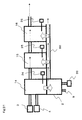
- FIG 1 is a configuration diagram of a hydrogen generation apparatus and a fuel cell system having the hydrogen generation apparatus in Embodiment 1 of the present invention.
- the fuel cell system in the present embodiment has a hydrogen generation apparatus 1 and a fuel cell 100.
- the hydrogen generation apparatus 1 is an apparatus which generates a gas containing hydrogen mainly by causing progress in reforming reaction between water vapor and a raw material containing an organic compound such as hydrocarbon constituted at least of carbon and hydrogen, e.g., city gas containing methane as a main constituent, natural gas or LPG.
- the fuel cell 100 is an apparatus which generates electric power by using as an anode gas the gas containing hydrogen supplied from the hydrogen generation apparatus 1, by using as a cathode gas an oxidizer such as air separately supplied, and by causing the two gases to react with each other.
- the hydrogen generation apparatus 1 is provided with a hydrogen generator 8 which generates the gas containing hydrogen from the raw material and water vapor.
- the hydrogen generator 8 is provided with a combustor 2 which generates heat for progress in reforming reaction.
- a combustible gas acting as a heating source in the combustor 2 the raw material passed through the hydrogen generator 8, anode off gas expelled from the anode of the fuel cell 100, or the like is used.
- a water supplier 3 which is a pump for supplying water to the hydrogen generator 8 and a raw material supplier 4 which supplies the raw material are provided on the hydrogen generation apparatus 1.
- the raw material supplier 4 is a booster pump for adjusting the flow rate by controlling, for example, input current pulses or input electric power.
- the water supplier 3 is a pump having a flow rate adjustment function, as in the case of the raw material supplier 4.
- a gas infrastructure path 6 is used as a raw material supply source.
- a desulfurizer 5 filled with a desulfurizing agent is connected to the gas infrastructure path 6 through a connection portion 7 and is connected to the raw material supplier 4.
- a hydrogen gas supply path 9 for supplying the fuel cell 100 with the gas containing hydrogen generated by the hydrogen generator 8 is also provided.
- an anode off gas supply path 10 for supplying the combustor 2 with the gas containing hydrogen not consumed in the fuel cell 100 is provided.
- a three-way valve 11 is provided at an intermediate position in the hydrogen gas supply path 9, and a bypass path 12 which connects the three-way valve 11 and the anode off gas supply path 10 by bypassing the fuel cell 100 is provided.
- an oxidizer gas supplier 110 which supplies air as an oxidizer gas to the fuel cell 100 is provided.
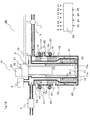
- FIG. 2 is a sectional view of the construction of the hydrogen generator 8.
- a reforming device 14 which causes progress in reforming reaction using the raw material and water vapor and a converting device 15 which causes converting reaction between carbon monoxide in the gas containing hydrogen generated by the reforming device 14 and water vapor are provided.
- the above-described reforming reaction may be either one of water vapor reforming reaction and autothermal reforming reaction.
- the hydrogen generator 8 is tubular and has the combustor 2 which is a burner for supplying reaction heat necessary for reforming reaction, and three annular spaces formed by a plurality of cylinders disposed concentrically on a combustion space 17 above the combustor 2.
- the three annular spaces are a first annular space 18 formed on the outer side of the combustion space 17, a second annular space 19 formed on the outer side of the first annular space 18 and a third annular space 29 formed on the inner side of the first annular space.
- An igniter 21 serving as an ignition source for the combustor 2, a flame rod 22 for sensing the state of combustion in the combustor 2 and a first air supplier 20 for supplying the combustor 2 with air for combustion are also provided.
- the first air supplier 20 is constituted by a fan for example.
- the first annular space 18 is formed so that the width of a lower annular space therein is larger than that of an upper annular space therein.
- the lower annular space is filled with a Ni-based reforming catalyst to form the reforming device 14.
- the second annular space 19 is formed so that the width of an upper annular space therein is larger than that of a lower annular space therein.
- the upper annular space is filled with a Cu-Zn-based converting catalyst to form the converting device 15.
- the raw material supplier 4 and an upper portion of the annular space 18 are connected to each other.
- the first annular space 18 and the second annular space 19 are connected to each other through their lower portions.
- the hydrogen gas supply path 9 is connected to an upper portion of the second annular space 19. That is, the raw material supplied from the raw material supplier 4 moves downward from above through the first annular space 18 by passing through the reforming device 14, thereafter moves upward from below through the second annular space 19 by passing through the converting device 15, and is discharged from the hydrogen generator 8 to be supplied to the fuel cell 100 through the hydrogen gas supply path 9 (see, dotted line arrows in Figure 2 ).
- the combustor 2 is disposed so that flame goes out downward therefrom.
- Combustion exhaust gas produced by combustion in the combustor 2 moves downward through the combustion space 17 in a combustion cylinder 28, is discharged from the downstream end of the combustion cylinder 28 and then turned backward, moves upward through the third annular space between the combustion cylinder 28 and a wall 17a, and is discharged to the outside of the hydrogen generator 8 through an exhaust port 27 (see solid line arrows in the figure).
- the third annular space corresponds to a combustion exhaust gas path 29. Heat contained in the combustion exhaust gas is transferred to the reforming device 14 and the converting device 15 through the wall 17a to heat the reforming device 14 and the converting device 15, thereby causing reactions therein.
- a first temperature sensor 24 and a second temperature sensor 25 are respectively provided on the reforming device 14 and the converting device 15 to sense the catalyst temperatures in the reforming device 14 and the converting device 15.
- a thermocouple, a thermistor or the like is used as each temperature sensor.
- the first temperature sensor 24 is disposed outside the reforming device 14 and in the vicinity of the outlet of the reforming device 14.
- the second temperature sensor 25 is disposed in the converting device 15.
- An operation controller 13 is provided to which detection values from the flame rod 22, the first temperature sensor 24 and the second temperature sensor 25 are input, and which controls functioning of components including the raw material supplier 4, the water supplier 3, the first air supplier 20, the three-way valve 11 and the igniter 21 (see Figure 1 ).
- the operation controller 13 uses a semiconductor memory and a CPU or the like, stores an operational functioning sequence of the hydrogen generation apparatus 1 and operation information including the raw material integrated flow rate, computes suitable functioning conditions according to conditions, and designates the functioning conditions for the components necessary for the system operation, including the water supplier 3 and the raw material supplier 4.
- the raw material is supplied from the raw material supplier 4 to the hydrogen generator 8 at a command from the operation controller 13.
- the three-way valve 11 is at a selected position on the bypass path 12 side. Accordingly, the raw material discharged from the hydrogen generator 8 is supplied to the combustor 2 via the bypass path 12.
- the raw material used as a fuel is ignited in the combustor 2 to start heating.
- the water supplier 3 After determining on the basis of temperature information obtained from the first temperature sensor 24 and the second temperature sensor 25 that a state in which dew condensation does not occur on each of catalyst layers in the reforming device 14 and the converting device 15 has been established, the water supplier 3 is operated to supply water to the hydrogen generator 8 to start reforming reaction between the water and the raw material.
- city gas (13A) having methane as a main constituent is used as the raw material. Water is supplied at such a rate that about 3 mols of water vapor exists with respect to 1 mol of carbon atoms in the average molecular formula of the supplied city gas (about 3 in terms of steam carbon ratio (S/C)).
- the reforming device 14 and the converting device 15 are warmed and reforming reaction and converting reaction progress.
- the concentration of carbon monoxide in the gas containing hydrogen is reduced to such a concentration that power generation in the fuel cell can be continued, the three-way valve 11 is changed to the fuel cell 100 side to supply the gas containing hydrogen from the hydrogen gas supply path 9 to the fuel cell 100.
- the temperature of the reforming device 14 at the time of power generation is about 650°C
- the temperature of the converting device 15 is about 150 to 200°C.
- the dew point of the mixture gas of the raw material and water vapor at the inlet of the reforming device 14 is about 93°C
- the gas dew point at the outlet of the reforming device 14 is about 68°C.
- the dew point of the gas at the outlet of the converting device 15 is about 61 °C.
- the oxidizer gas supplier 110 is shut down and the operation of the hydrogen generation apparatus 1 is also shut down.
- the outline of the method of shutting down the operation of the hydrogen generation apparatus 1 will be described.
- the combustion in the combustor 2 is also stopped and the temperature of the catalyst layers in the reforming device 14 and the converting device 15 in the hydrogen generator 8 are reduced.
- the raw material is supplied to the hydrogen generation apparatus 1 to replace with the raw material the gas containing hydrogen staying in the gas paths in the hydrogen generation apparatus 1.
- Specific functioning in the present embodiment resides in functioning of the operation controller 13 at the time of apparatus shutdown according to the shutdown method described below.
- the three-way valve 11 is opened on the fuel cell 100 side to perform replacement with the raw material gas in the fuel cell 100 as well.
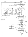
- FIG 3 is a diagram showing a control flow according to the method of shutting down the hydrogen generation apparatus 1 in Embodiment 1.
- each step is indicated by an abbreviated symbol S.
- step 1 the operation controller 13 stops the functioning of the combustor 2, the water supplier 3 and the raw material supplier 4 at a shutdown command.
- This step of shutting down the combustor 2 corresponds to an example of the first step in the present invention.
- a detected temperature T K sensed by the first temperature sensor 24 is, for example, about 650°C
- a detected temperature T H sensed by the second temperature sensor 25 is, for example, about 150°C.
- step 2 determination is made as to whether the detected temperature T K is higher than a temperature T 1 set in advance.
- the temperature T 1 is a temperature at which the raw material supplier 4 is made to function to replace the gas containing hydrogen with the raw material, and at which precipitation of carbon from the raw material when the raw material is caused to flow through the reforming device 14 is limited.
- the temperature T 1 is an example of the predetermined temperature T 1 in the present invention. For example, if the reforming catalyst is a Ni catalyst, the temperature T 1 can be set to about 150 to 350°C.
- step 8 corresponds to an example of the third step.
- step 2 if the detected temperature T K is higher than the temperature T 1 , the control proceeds to step 3 to determine whether or not the detected temperature T K is equal to or higher than a reference temperature T 3 set in advance.
- the reference temperature T 3 is set to a temperature higher than the temperature T 1 .
- the reference temperature T 3 can be set to 400°C.
- the reference temperature T 3 will be again described with respect to steps 5 and 6.
- the reference temperature T 3 corresponds to an example of the third temperature in the present invention.
- the control proceeds to step 4 if the detected temperature T K is equal to or higher than T 3 , and determines whether or not the detected temperature T H sensed by the second temperature sensor 25 is equal to or lower than a first reference temperature T 2 set in advance.
- the first reference temperature T 2 corresponds to an example of the first temperature in the present invention.
- the first reference temperature T 2 is set to a temperature at which dew condensation does not occur, and which is at least higher than the dew point of the gas in the converting device 15.
- a temperature at which water vapor does not condense is considered as the first reference temperature T 2 .
- the first reference temperature T 2 may be set to 80 to 150°C.
- step 4 If in step 4 the detected temperature T H dropping naturally is equal to or lower than T 2 , the control proceeds to step 5 to start functioning of the first air supplier 20. This is because in such a situation where the detected temperature T H is equal to or lower than the first reference temperature T 2 , a probability of the temperature of the converting catalyst becoming lower than the gas dew point before the detected temperature T K reaches the temperature T 1 is assumable. In step 5, therefore, the first air supplier 20 is made to function to apply heat from the reforming device 14 to the converting device 15, as described below.
- Figure 4 is an enlarged diagram of a portion of the hydrogen generator 8.
- Air supplied downward from the first air supplier 20 moves from below to above as indicated by arrow A. That is, the air moves through the above-described combustion exhaust gas path 29.
- the air absorbs heat from the reforming device 14 in a lower section of the path to increase its temperature (see arrow B).
- the air having the increased temperature moves upward and gives heat to the converting device 15 (see arrow C).
- heat from the reforming device 14 is transferred to the converting device 15 through the medium of air supplied from the first air supplier 20, thus enabling limiting of the reduction in temperature of the converting device 15.
- the first air supplier 20 continues functioning until in step 6 the detected temperature T K becomes lower than the reference temperature T 3 or the detected temperature T H becomes equal to or higher than a second reference temperature T 4 .
- the control proceeds to step 7 to stop functioning of the first air supplier 20.
- the reference temperature T 3 also described with respect to step 3 is set as such a temperature that when the temperature of the reforming device 14 is lower than T 3 , a sufficiently large influence cannot be exerted on the increase in temperature of the converting device 15 while the first air supplier 20 is functioning.
- the second reference temperature T 4 is an example of the second temperature in the present invention.
- the second reference temperature T 4 is set to a temperature higher than the first reference temperature T 2 .
- the second reference temperature T 4 may be set equal to the first reference temperature T 2 .
- the second reference temperature T 4 is set to such a value as to provide a hysteresis for improving the controllability. That is, it is preferable to set the second reference temperature T 4 to such a temperature that turning on/off of the first air supplier 20 is not frequently performed.
- the second reference temperature T 4 may be set to a temperature higher by 5 to 10°C than the first reference temperature T 2 .
- step 2 After shutdown of the first air supplier 20 in step 7, a return to step 2 is again made to repeat the same steps as those described above.
- the detected temperature T K only decreases from the temperature 650°C at the time of shutdown command, as mentioned above. Therefore, once the detected temperature T K becomes lower than the reference temperature T 3 , it does not again become higher than T 3 . For this reason, if it is determined in step 3 or 6 that the detected temperature T K is lower than T 3 , steps 2 and 3 are repeated. That is, the first air supplier 20 is not made to function until the detected temperature T K reaches the temperature T 1.
- step 4 If in step 4 the detected temperature T H is higher than the first reference temperature T 2 , the control returns to the second step by assuming that there is still no risk of dew condensation.
- steps 2 to 7 are repeated as required to make the first air supplier function so that the temperature of the gas in the CO reducing device is not equal to or lower than the dew point.
- This group of steps corresponds to an example of the second step in the present invention.
- the first air supplier 20 is made to function so that dew condensation does not occur in the converting device 15 before the temperature of the reforming device 14 reaches the temperature at which purge with the raw material is performed, and heat is transferred from the reforming device 14 at a comparatively high temperature to the converting device 15 by using air as a heat-transfer medium to keep the converting device 15 warm.
- steps 5 and 7 are ordinarily repeated as described above, functioning of the first air supplier 20 is intermittently performed.
- Functions to shut down the hydrogen generation apparatus 1 were performed by preparing a program with the temperature T 1 set to 320°C, the first reference temperature T 2 and the second reference temperature T 4 set to 120°C and the reference temperature T 3 set to 400°C in the control flow of the shutdown method for the hydrogen generation apparatus 1 in Figure 3 .
- the rate of supply of air by the first air supplier 20 was set to 5 NUmin.
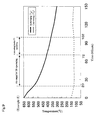
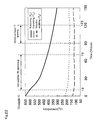
- Figure 5 is a diagram showing a graph of changes in the detected temperature T K and the detected temperature T H with respect to time.
- the first air supplier 20 was made to function from a time 20 minutes after shutdown to a time 72 minutes after shutdown on the basis of the above-described flow from step 2 to step 7.
- the detected temperature T K became equal to 320°C
- the detected temperature T H was 99°C. Even after repeating startup and shutdown 100 times, no reductions in strength and no reductions in activity of the catalysts were recognized.
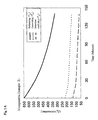
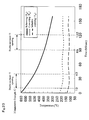
- Figure 6 is a diagram showing a graph of changes in the detected temperature T K and the detected temperature T H with respect to time.
- the detected temperature T K became equal to 320°C
- the detected temperature T H was 79°C.
- the converting catalyst was taken out to measure its strength. The strength was reduced to 70% of the initial value. Also, the activity was reduced to 75% of the initial value.
- the shutdown method for the hydrogen generation apparatus 1 in the present Embodiment 1 was recognized as advantageous in terms of limiting of dew condensation.
- the catalysts in the present invention are not necessarily limited to those used in the present embodiment.
- a Ru-based catalyst may be used as a reforming catalyst.
- cooling conditions vary with respect to kinds of catalyst.
- a Ru catalyst as a reforming catalyst is widely adopted particularly in hydrogen generation apparatuses for fuel cells in home use because of, for example, its good usability relating to its low liability to receive carbon precipitation, but it is high in cost.
- the Ni catalyst used in the present Embodiment 1 can be obtained at a low cost but it is liable to receive carbon precipitation in comparison with the Ru catalyst and therefore necessitates reducing the temperature at which purge (replacement) in the apparatus using the raw material can be performed in comparison with the Ru catalyst.
- the upper limit temperature at which purge can be performed is about 400 to 500°C on the Ru catalyst and is about 300 to 400°C on the Ni catalyst.
- the catalysts in the reaction sections in the hydrogen generation apparatus are different in the temperatures of use and the amounts of use depending on the configuration of the apparatus.
- the temperature at which dew condensation occurs also varies. Therefore, different conditions of cooling during shutdown result.
- the conditions of cooling in the reforming device and the converting device vary with respect to kinds of catalyst, and the conditions of reduction in temperature vary depending on the configuration of the apparatus.
- suitable reference values T 1 to T 4 selected on an apparatus-by-apparatus basis are employed to enable limiting of degradation of the converting catalyst due to dew condensation.
- the reference temperature T 3 is set to 400°C, higher than the temperature T 1 300°C, the temperatures T 3 and T 1 may alternatively be set equal to each other.
- control of the first air supplier 20 is not performed when the detected temperature T K is lower than the reference temperature T 3 .
- raw material purge is performed by making the raw material supplier 4 function when the detected value from the first temperature sensor 24, i.e., the detected temperature T K , decreases to the temperature T 1 .
- the first temperature sensor 24 may be removed and the raw material supplier 4 may be made to function after a lapse of a predetermined time period from the time when the combustor 2 is shut down.
- This predetermined time period is the time period from the time when the combustor 2 is shut down to the time when the temperature of the reforming device 14 reaches the temperature suitable for raw material purge. Details of this procedure will be described below.
- the second reference temperature T 4 higher than the first reference value T 2 is set to provide a hysteresis for improvement in controllability.
- the temperatures T 4 and T 2 may alternatively be set equal to each other, as described above.
- a combination of these settings may be made to perform control during the predetermined time period after the shutdown command and before the execution of raw material purge so that the first air supplier 20 is made to function when the detected temperature T H becomes equal to or lower than the first reference temperature T 2 , and is shut down when the detected temperature T H becomes higher than the first reference temperature T 2 .
- the temperatures are directly sensed by using the first temperature sensor 24 and the second temperature sensor 25. This temperature sensing is not necessarily required. Each temperature can be detected by utilizing a physical variable having a correlation with the temperature without such a temperature sensor.
- the temperature can be indirectly grasped by utilizing the lapse of time from the time when the combustor 2 is shut down. That is, data is taken under various conditions. For example, it is assumed that the time taken to reduce the temperature of the converting device 15 to the first reference temperature T 2 under a standard environmental condition is experimentally found to be 20 minutes from the time when the shutdown is made (see Figure 5 ). That is, it can be supposed that the temperature of the converting device 15 decreases to the first reference temperature T 2 after a lapse of 20 minutes from the time when the shutdown is made. It is possible to measure the temperature with a timer in this way without using the second temperature sensor 25.
- data is assumed to be taken which indicates that the temperature of the converting device 15 reaches the second reference temperature T 4 after a lapse of 3 minutes from a start of functioning of the first air supplier 20 made after the above-described decrease in temperature.
- Various data items are also assumed to be thereafter taken according to such timing that dew condensation is avoided, while shutting down the first air supplier 20.
- the first temperature sensor 24 and the second temperature sensor 25 may be removed and control may be performed so as to make the first air supplier 20 function by predetermined timing such that dew condensation does not occur in the converting device 15 before raw material purge is performed.
- control may be performed so as to make the first air supplier 20 function by predetermined timing such that dew condensation does not occur in the converting device 15 before raw material purge is performed.
- the gas temperature in the CO reducing device is equal to or lower than the dew point
- the gas temperature in the CO reducing device is equal to or lower than the first temperature
- the gas temperature in the CO reducing device is equal to or higher than the second temperature
- the temperature of the reforming device is equal to or higher than the third temperature
- the gas temperature in the CO reducing device indirectly detected is “equal to or lower than the dew point", “equal to or lower than the first temperature", “equal to or higher than the second temperature” or “equal to or higher than the third temperature”.
- a hydrogen generation apparatus and a fuel cell system having the hydrogen generation apparatus in Embodiment 2 of the present invention will be described below.
- the hydrogen generation apparatus and the fuel cell system having the hydrogen generation apparatus in the present Embodiment 2 have basically the same configuration as that in Embodiment 1.
- the configuration in the present Embodiment 2 differs from that in Embodiment 1 in that a first heater for heating the converting device 15 is provided in the hydrogen generation apparatus. Description will therefore be made mainly of this point of difference.
- the same components as those in Embodiment 1 are indicated by the same reference characters.
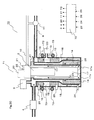
- FIG 7 is a sectional configuration diagram of a hydrogen generator 41 of a hydrogen generation apparatus 40 in the present Embodiment 2.
- the hydrogen generator 41 has a first heater 30 provided on a side surface of the converting device.
- the first heater 30 is a sheath heater for heating the converting device 15.
- the first heater 30 corresponds to an example of the heater in the present invention.
- an operation controller 42 which controls the first heater 30 as well is provided in place of the operation controller 13 in Embodiment 1.
- Figure 8 is a diagram showing the control flow of the method of shutting down the hydrogen generation apparatus 40 in the present Embodiment 2.
- the same steps as those in Embodiment 1 are indicated by the same reference characters.
- Steps 1 and 2 in the control flow shown in Figure 8 are the same as those in Embodiment 1. If in step 3 the detected temperature T K becomes lower than the reference temperature T 3 , the control proceeds to step 21. In step 21, determination is made as to whether or not the detected temperature T H is equal to or lower than the first reference temperature T 2 .
- the operation controller 42 sets the first heater 30 in an on-state in step 22. If the detected temperature T H is higher than the first reference temperature T 2 , the operation controller 42 sets the first heater 30 in an off-state in step 23. The control then proceeds to step 2 again.
- a mode may be adopted in which a step of maintaining the first heater 30 in the on-state until the detected temperature becomes equal to or higher than the reference temperature T4 is performed in place of the above-described step 23.
- the detected temperature T K changes only in a decreasing direction after the shutdown command and does not become high, as also described in the description of Embodiment 1. Therefore, if in step 3 or 6 the detected temperature T K is lower than the reference temperature T 3 , steps 2 and 3 are repeated.
- on-off control of the first heater 30 is performed after the detected temperature T K has become lower than the reference temperature T 3 and before the detected temperature T K reaches the temperature T 1.
- the converting catalyst is naturally cooled after the detected temperature T K has become lower than the reference temperature T 3 and before the detected temperature T K reaches the temperature T 1.
- the converting catalyst is heated by the heater and, therefore, the effect of limiting the occurrence of dew condensation can be increased relative to that of the hydrogen generation apparatus in Embodiment 1.
- the first heater 30 may be turned on when the first air supplier 20 is made to function in step 5, although this tuming-on is not shown in Figure 8 . Not only the heating action through air but also the heating action through the first heater 30 is exerted thereby, thus realizing a faster rise in temperature of the converting catalyst.
- step 7 includes turning off the first heater 30 as well as stopping functioning of the first air supplier 20.
- Functions to shut down the hydrogen generation apparatus 1 were performed by preparing a program with the temperature T 1 set to 280°C, the first reference temperature T 2 and the second reference temperature T 4 each set to 120°C and the reference temperature T 3 set to 400°C in the control flow of the shutdown method for the hydrogen generation apparatus 1 in Figure 8 .
- the output from the first heater 30 was set to 200 W, and the rate of supply of air by the first air supplier 20 was set to 5 NL/min.
- Figure 9 is a diagram showing a graph of changes in the detected temperature T K and the detected temperature T H with respect to time.
- the first air supplier 20 functioned intermittently from a time 20 minutes after shutdown to a time 72 minutes after shutdown on the basis of the flow from step 2 to step 7.
- the first heater 30 functioned intermittently from the time 72 minutes after shutdown to a time 102 minutes after shutdown on the basis of the flow of steps 2, 3, and 21 to 23.
- the detected temperature T H increases even after functioning of the first heater 30. This is an overshoot due to low heater response.
- the shutdown method for the hydrogen generation apparatus in the present Embodiment capable of limiting dew condensation by means of the combination of warm-keeping functioning based on supply of air and warm-keeping functioning with the heater was recognized as advantageous.
- Example 2 The power consumption in Example 2 was 105.2 Wh: combustion fan functioning (6 W x 52 min) plus first heater functioning (200 W x 30 min).
- Comparative Example 2 functions to shut down the hydrogen generation apparatus were performed by using a control flow formed by removing steps 4 to 7 in the control flow shown in Figure 8 . If the detected temperature T K is equal to or higher than T 3 in step 3 in this comparative example, the control returns to step 2. That is, this Comparative Example 2 is an example of limiting the occurrence of dew condensation in the converting device 15 only with the first heater 30.
- Figure 10 is a diagram showing a graph of changes in the detected temperature T K and the detected temperature T H with respect to time.
- the first heater 30 functioned intermittently from a time 20 minutes after shutdown to a time 50 minutes after shutdown and from a time 100 minutes after shutdown to a time 130 minutes after shutdown on the basis of the flow of steps 2, 3, and 21 to 23.
- the detected temperature of the first temperature sensor 24 became equal to 300°C
- the detected temperature of the second temperature sensor 25 was 128°C. Even after repeating startup and shutdown 100 times, no reductions in strength and no reductions in activity of the catalysts were recognized. It was thereby understood that dew condensation was limited by warm-keeping with the heater.
- the power consumption in Comparative Example 2 was 200 W. It can be understood that shutdown can be performed while limiting dew condensation with less energy in Example 2. That is, as shown in Example 2, heat from the reforming device 14 is utilized, though partially, in place of heat from the heater to limit the reduction in temperature of the converting device 15, thus reducing the power consumption.
- the embodiment has been described only with respect to use of the first heater 30 at the time of operation shutdown.
- the first heater 30 may be operated at the time of startup or during ordinary operation for the purpose of increasing the temperature of the converting catalyst.
- a hydrogen generation apparatus and a fuel cell system having the hydrogen generation apparatus in Embodiment 3 of the present invention will be described below.
- the hydrogen generation apparatus and the fuel cell system having the hydrogen generation apparatus in the present Embodiment 3 have basically the same configuration as that in Embodiment 1.
- the configuration in the present Embodiment 3 differs from that in Embodiment 1 in that a CO oxidizing device is provided in the hydrogen generation apparatus. Description will therefore be made mainly of this point of difference.
- the same components as those in Embodiment 1 are indicated by the same reference characters.
- FIG 11 is a sectional configuration diagram of a hydrogen generator 51 of a hydrogen generation apparatus 50 in the present Embodiment 3.
- the hydrogen generator 51 has a CO oxidizing device 16 which mostly oxidizes and reduces carbon monoxide remaining in the gas containing hydrogen after passing through the converting device 15.
- a Ru-based CO oxidizing catalyst is packed in the second annular space 19 on the downstream side of the converting device 15 to constitute the CO oxidizing device 16.
- a second air supplier 23 is provided which supplies air to be used for oxidation to the gas containing hydrogen downstream of the converting device 15.
- a third temperature sensor 26 for detecting the temperature of the CO oxidizing device 16 is also provided.
- an operation controller 52 to which a detected temperature T S from the third temperature sensor 26 is also input is provided in place of the operation controller 13 in Embodiment 1.
- a thermocouple, a thermistor or the like can be used as the third temperature sensor 26, a thermocouple, a thermistor or the like can be used.
- Figure 12 is a diagram showing the control flow of the method of shutting down the hydrogen generation apparatus 50 in the present Embodiment 3.
- the control flow shown in Figure 12 includes steps corresponding to but different from steps 4 and 6 in the control flow in Embodiment 1.
- the other steps in the control flow shown in Figure 12 are the same as those in Embodiment 1 and are indicated by the same reference characters.
- step 34 determination is made as to whether or not the detected temperature T H is equal to or lower than the first reference temperature T 2 or whether or not the detected temperature T S is equal to or lower than a first reference temperature T 5 .
- the first reference temperature T 5 is a temperature at which dew condensation does not occur in the CO oxidizing device 16.
- the first reference temperature T 5 is set at least higher than the dew point of the gas in the CO oxidizing device 16.
- the first reference temperature T 5 is an example of the first temperature in the present invention set with respect to the gas temperature in the CO oxidizing device 16.
- the first reference temperature T 5 may be set, for example, to the same temperature 120°C as the first reference temperature T 2 .
- step 34 if it is determined in step 34 that at least one of the temperature of the converting device 15 and the CO oxidizing device 16 is lower than the reference temperature, the control proceeds to step S5 to cause the first air supplier 20 start functioning.
- the air supplier 20 heat from the reforming device 14 is transferred to the converting device 15 and to the CO oxidizing device 16 through the medium of air, thereby limiting the reductions in the temperatures of the converting device 15 and the CO oxidizing device 16.
- step 36 The control then proceeds to step 36 to stop functioning of the first air supplier 20 if the detected temperature T K is lower than the reference temperature T 3 , or if the detected temperature T H is equal to or higher than the second reference temperature T 4 and the detected temperature T S is equal to or higher than a second reference temperature T 6 .
- the first air supplier 20 is shut down if the temperature of the reforming device 14 becomes lower than the temperature T 3 at which a sufficiently large influence cannot be exerted on the temperatures of the converting device 15 and the CO oxidizing device 16, as in the case of Embodiment 1. Further, if each of the detected temperature T H and the detected temperature T S becomes equal to or higher than the second reference temperature, functioning of the first air supplier 20 is also stopped by assuming that there is no risk of dew condensation.
- the second reference temperature T 6 is an example of the predetermined temperature T 6 in the present invention set with respect to the gas temperature in the CO oxidizing device 16. The second reference temperature T 6 is set equal to or higher than the first reference temperature T 5 .
- the second reference temperature T 6 may be set equal to the first reference temperature T 5 .
- the second reference temperature T 6 is set to a temperature higher than the first reference temperature T 5 so as to provide a hysteresis for the purpose of improving the controllability. That is, it is preferable to set the second reference temperature T 6 to such a temperature that turning on/off of the first air supplier 20 is not frequently performed.
- the second reference temperature T 6 may be set to a temperature higher by 5 to 10°C than the first reference temperature T 5 .
- Example 3 an experiment was made by using the hydrogen generation apparatus 50 having the configuration described in the above-described embodiment.
- Functions to shut down the hydrogen generation apparatus 1 were performed by preparing a program with the temperature T 1 set to 320°C, the first reference temperature T 2 , the second reference temperature T 4 , the first reference temperature T 5 and the second reference temperature T 6 set to 120°C and the reference temperature T 3 set to 400°C in the control flow of the shutdown method for the hydrogen generation apparatus 50 in Figure 12 .
- the rate of supply of air by the first air supplier 20 was set to 5 NUmin.
- Figure 13 is a diagram showing a graph of changes in the detected temperature T K , the detected temperature T H and the detected temperature T S with respect to time.
- the first air supplier 20 intermittently executed functioning from a time 13 minutes after shutdown to a time 73 minutes after shutdown on the basis of the flow from step S2 to step S7.
- the detected temperature T K became equal to 320°C
- the detected temperature T S was 103°C. Even after repeating startup and shutdown 100 times, no reductions in strength and no reductions in activity were recognized. The shutdown method enabling prevention of dew condensation was thus recognized as advantageous.
- Figure 14 is a diagram showing a graph of changes in the detected temperature T K , the detected temperature T H and the detected temperature T S with respect to time.
- the detected temperature T K became equal to 320°C
- the detected temperature T S was 64°C.
- the CO oxidizing catalyst was taken out to measure its activity. The activity was reduced to 70% of the initial value.
- the shutdown method for the hydrogen generation apparatus 50 in the present Embodiment 3 was recognized as advantageous in terms of limiting of dew condensation.
- the CO oxidizing device 16 is not provided.
- the reason for not providing the CO oxidizing device 16 is that in some cases the concentration required of carbon monoxide in the gas containing hydrogen produced in the hydrogen generation apparatus 1 is not so low, depending on the performance of the fuel cell. In such a case, it is not necessarily required that the CO oxidizing device 16 be provided in the hydrogen generation apparatus 1. More specifically, in a case where the hydrogen generation apparatus 1 is used by being connected to a solid-oxide fuel cell, a phosphoric acid fuel cell or the like having high CO resistance, it is not necessary to provide the CO oxidizing device 16.
- the CO oxidizing device 16 is provided in the hydrogen generation apparatus 50 in the present Embodiment 3, enabling use of a fuel cell having lower resistance to carbon monoxide (CO) in comparison with the fuel cell 100 used in Embodiment 1.
- CO carbon monoxide
- a CO methanizing device is provided in place of the CO oxidizing device. In this case, there is no need to supply air for oxidation and, hence, no need to provide the second air supplier 23 or the like.
- the above-described converting device and CO oxidizing device or CO methanizing device correspond to an example of the CO reducing device in the present invention.
- the temperature T 1, the first reference temperature T 2 , the reference temperature T 3 , the second reference temperature T 4 , the first reference temperature T 5 and the second reference temperature T 6 set in the above-described shutdown flow may be determined according to the characteristics of the catalysts used in the reforming device 14, the converting device 15 and the CO oxidizing device 16 and the water vapor condensation temperature, and are not limited to the values described in the present embodiment.
- the temperature T 1 be a temperature at which carbon precipitation from the raw material gas is limited. With respect to the Ni catalyst, such a temperature is about 150 to 350°C.
- As the first reference temperature T 2 and the first reference temperature T 5 a temperature at which water vapor does not condense is preferably considered. Such a temperature is 80 to 150°C.
- the hydrogen generation apparatus 50 in the present Embodiment 3 there is a risk of dew condensation occurring faster in the CO oxidizing device 16 than in the converting device 15 at the time of shutdown, for example, as shown by the data on Example 3, because the temperature of the CO oxidizing device 16 during operation is ordinarily lower than that of the converting device 15.
- the converting device 15 is at about 150°C, as described in Example 3. It is understood that the temperature at which caution against dew condensation should be exercised is not reached at the time of supply of the raw material. Therefore, control of the first air supplier 20 may be performed by considering only the reduction in temperature of the CO oxidizing device 16 detected with the third temperature sensor 26. In such a case, the second temperature sensor 25 may be removed.
- Figure 15 is a flowchart in a case where control of the first air supplier 20 is performed by considering only the reduction in temperature of the CO oxidizing device 16 detected with the third temperature sensor 26 as described above.
- step 34 in Figure 12 is replaced with step 134 in which determination is made only as to whether or not the detected temperature T S is equal to or lower than the first reference temperature T 5 .
- step 36 in Figure 12 is replaced with step 136 in which determination is made as to whether or not the detected temperature T K is lower than the first reference temperature T 3 or whether or not the detected temperature T S is equal to or higher than the second reference temperature T 6 .
- Functioning of the first air supplier 20 may be controlled by sensing only the temperature of the CO oxidizing device 16 in the above-described way. In some instances, however, the temperature on the downstream side of the converting device 15 and the temperature on the upstream side of the CO oxidizing device 16 are considerably close to each other, depending on the configuration of the hydrogen generator. Therefore, control of the first air supplier 20 by sensing both the temperature of the converting device 15 and the CO oxidizing device 16 as in the present Embodiment 3 is more preferable.
- the reference temperatures for the converting device 15 and the CO oxidizing device 16 are set equal to each other.
- the reference temperatures may alternatively be set different from each other according to the gas dew points therein.
- first temperature sensor 24 and the second temperature sensor 25 may be removed and the first air supplier 20 may be made to function on the basis of a lapse of time after shutdown of the combustor 2, as described above in Embodiment 1.
- the second reference temperature T 6 higher than the first reference temperature T 5 is set to provide a hysteresis for the purpose of improving the controllability.
- the temperatures T 6 and T 5 may alternatively be set equal to each other.
- the first reference temperature T 2 and the second reference temperature T 4 may be set in the same way.
- a combination of these settings may be made to perform control after the shutdown command and before the execution of raw material purge so that the first air supplier 20 is made to function when the detected temperature T H becomes equal to or lower than the first reference temperature T 2 or the detected temperature T S becomes equal to or lower than the first reference temperature T 5 , and is shut down when the detected temperature T H becomes higher than the first reference temperature T 2 and the detected temperature T S becomes equal to or higher than the first reference temperature T 5 .
- the first temperature sensor 24, the second temperature sensor 25 and the third temperature sensor 26 may be removed and control may be performed so as to make the first air supplier 20 function by predetermined timing such that dew condensation does not occur in the converting device 15 and in the CO oxidizing device 16 before raw material purge is performed.
- the first temperature sensor 24, the second temperature sensor 25 and the third temperature sensor 26 may be removed and control may be performed so as to make the first air supplier 20 function by predetermined timing such that dew condensation does not occur in the converting device 15 and in the CO oxidizing device 16 before raw material purge is performed.
- functioning of the first air supplier 20 is stopped if the condition in step 36 is satisfied after a start of functioning of the first air supplier 20.
- the first air supplier 20 may alternatively be made to continue functioning without being shut down before raw material purge is performed. From the viewpoint of energy saving, however, it is more preferable to shut down the first air supplier 20 after the temperature of the converting device 15 has increased.
- a hydrogen generation apparatus and a fuel cell system having the hydrogen generation apparatus in Embodiment 4 of the present invention will be described below.
- the fuel cell system in the present Embodiment 4 have basically the same configuration as that in Embodiment 3.
- the configuration in the present Embodiment 4 differs from that in Embodiment 3 in that a first heater for heating the converting device 15 and a second heater for heating the CO oxidizing device 16 are provided in the hydrogen generation apparatus. Description will therefore be made mainly of this point of difference.
- the same components as those in Embodiment 3 are indicated by the same reference characters.
- FIG 16 is a sectional configuration diagram of a hydrogen generator 61 of a hydrogen generation apparatus 60 in the present Embodiment 4.
- the hydrogen generator 61 has a first heater 30 provided on a side surface of the converting device 15.
- the first heater 30 is a sheath heater for heating the converting device 15.
- the hydrogen generator 61 also has a second heater 31 provided on a side surface of the CO oxidizing device 16.
- the second heater 31 is a sheath heater for heating the CO oxidizing device 16.
- the second heater 31 corresponds to an example of the heater in the present invention provided on the CO oxidizing device.
- An operation controller 62 which controls the first heater 30 and the second heater 31 as well is provided in place of the operation controller 52 in Embodiment 3.
- Figure 17 is a diagram showing the control flow of the method of shutting down the hydrogen generation apparatus 60 in the present Embodiment 4.
- the control flow shown in Figure 17 includes steps 41 to 46 in which the control proceeds in the case where the result of determination in step 3 is NO, in addition to the control flow in Embodiment 3.
- the same steps as those in Embodiment 3 are indicated by the same reference characters.
- step 41 determination is made as to whether or not the detected temperature T H is equal to or lower than the first reference temperature T 2 .
- step 41 If in step 41 the detected temperature T H is equal to or lower than the first reference temperature T 2 , the control proceeds to step 42 and the operation controller 42 sets the first heater 30 in the on-state. If the detected temperature T H is higher than the first reference temperature T 2 , the control proceeds to step 43 and the operation controller 42 sets the first heater 30 in the off-state.
- step 44 determination is made as to whether or not the detected temperature T S is lower than the first reference temperature T 5 .
- step 45 If the detected temperature T S is equal to lower than the first reference temperature T 5 , the control proceeds to step 45 and the operation controller 42 sets the second heater 31 in the on-state. If the detected temperature T S is higher than the first reference temperature T 5 , the control proceeds to step 46 and the operation controller 42 sets the second heater 31 in the off-state.
- the detected temperature T K does not become high after the shutdown command. Therefore, once the detected temperature T K becomes lower than the reference temperature T 3 in step 3 or 6, the loop of steps 2, 3, and 41 to 46 is repeated until the detected temperature T K reaches the temperature T 1 , thus performing temperature control with the heaters and more reliably limiting the occurrence of dew condensation in the converting device 15 and the CO oxidizing device 16.
- Functions to shut down the hydrogen generation apparatus 1 were performed by preparing a program with the temperature T 1 set to 280°C, the first reference temperature T 2 , the second reference temperature T 4 , the first reference temperature T 5 and the second reference temperature T 6 each set to 120°C and the reference temperature T 3 set to 400°C in the control flow of the shutdown method for the hydrogen generation apparatus 60 in Figure 17 .
- On-off control was performed by controlling the voltage so that the first heater 30 heating the converting device 15 had a capacity of 180 W and the second heater 31 heating the CO oxidizing device 16 had a capacity of 80 W.
- the rate of supply of air by the first air supplier 20 was set to 5 NL/min.
- Figure 18 is a diagram showing a graph of changes in the detected temperature T K , the detected temperature T H and the detected temperature T S with respect to time.
- the first air supplier 20 intermittently executed functioning from a time 13 minutes after shutdown to a time 73 minutes after shutdown on the basis of the flow of steps 2, 3, 34, 5, 36, and 7.
- the first heater 30 did not function.
- the second heater 31 functioned completely for 33 minutes from a time 90 minutes after shutdown to a time 123 minutes after shutdown on the basis of steps 2, 3, 51, 52, and 53.
- the shutdown method for the hydrogen generation apparatus in the present embodiment capable of limiting dew condensation by means of the combination of warm-keeping functioning based on supply of air and warm-keeping functioning with the heaters was recognized as advantageous.
- Example 4 The power consumption in Example 4 was 50 Wh: combustion fan functioning (6 W x 60 min) plus second heater 31 functioning (80 W x 33 min).
- Comparative Example 4 functions to shut down the hydrogen generation apparatus were performed by using a control flow formed by removing steps 34, 5, 36, and 7 in the control flow shown in Figure 17 . If the detected temperature T K is equal to or higher than T 3 in step 3 in Comparative Example 4, the control returns to step 2. That is, Comparative Example 4 is an example of limiting the occurrence of dew condensation in the converting device 15 and in the CO oxidizing device 16 only with the first heater 30 and the second heater 31.
- Figure 19 is a diagram showing a graph of changes in the detected temperature T K , the detected temperature T H and the detected temperature T S with respect to time.
- the first heater 30 did not function based on steps 2, 3, and 41 to 46.
- the second heater 31 functioned for 30 minutes from a time 13 minutes after shutdown to a time 43 minutes after shutdown and for 33 minutes from a time 89 minutes after shutdown to a time 122 minutes after shutdown, a total of 66 minutes.
- T K became equal to 300°C
- T S was 119°C. Even after repeating startup and shutdown 100 times, no reductions in strength and no reductions in activity of the catalysts were recognized. It was thereby understood that dew condensation was limited by warm-keeping with the heaters.
- the power consumption in Comparative Example 4 was 88 Wh. It can be understood that shutdown can be performed while limiting dew condensation with less energy in Example 4. That is, as shown in Example 4, heat from the reforming device 14 is utilized, though partially, in place of heat from the heaters to limit the reductions in the temperatures of the converting device 15 and the CO oxidizing device 16, thus reducing the power consumption.
- Example 4 with respect to the converting device 15, the temperature at which dew condensation occurs was not reached, even though the first heater 30 was not turned on. If it is known in advance that at the time of supply of the raw material the temperature of the converting device 15 does not reach the temperature at which caution against dew condensation should be exercised, the provision of the first heater 30 is not required.
- a hydrogen generation apparatus and a fuel cell system having the hydrogen generation apparatus in Embodiment 5 have basically the same configuration as that of the hydrogen generation apparatus and the fuel cell system having the hydrogen generation apparatus in Embodiment 4.
- the configuration in Embodiment 5 differs from that in Embodiment 4 in that the first heater 30 and the second heater 31 are connected in series. That is, while in Embodiment 4 the first heater 30 and the second heater 31 can be individually on-off controlled, the corresponding heaters in the present Embodiment 5 are controllable only in such a way as to be controlled simultaneously with each other. Description will therefore be made mainly of this point of difference.
- the same components as those in Embodiment 4 are indicated by the same reference characters.
- FIG 20 is a sectional configuration diagram of a hydrogen generator 71 of a hydrogen generation apparatus 70 in the present Embodiment 5.
- the hydrogen generator 71 provided in the hydrogen generation apparatus 70 has a double-use heater 73 formed of a first heater and a second heater connected in series.
- an operation controller 72 which controls the double-use heater 73 is provided in place of the operation controller 62 in Embodiment 4 that controls the first heater 30 and the second heater 31 separately from each other.
- Figure 21 is a diagram showing the control flow of the method of shutting down the hydrogen generation apparatus 70 in the present Embodiment 5.
- steps 51 to 53 are provided in place of steps 41 to 46 in Embodiment 4.
- steps 41 to 46 are indicated by the same reference characters.
- step 51 determination is made as to whether or not the detected temperature T H is equal to or lower than the first reference temperature T 2 or whether or not the detected temperature T S is equal to or lower than the first reference temperature T 5 .
- the operation controller 72 sets the double-use heater 73 in the on-state. If the detected temperature T H is higher than the first reference temperature T 2 and the detected temperature T S is higher than the first reference temperature T 5 , the operation controller 72 sets the double-use heater 73 in the off-state. That is, control is performed so as to prevent dew condensation by setting the double-use heater 73 in the on-state when at least one of the temperatures of the converting device 15 and the CO oxidizing device 16 becomes smaller than the first reference temperature.
- the detected temperature T K does not rise but only decreases. Therefore, once the detected temperature T K becomes lower than the reference temperature T 3 in step 3 or 6, the loop of steps 2, 3, and 51 to 53 is repeated until the detected temperature T K reaches the temperature T 1, thus performing temperature control with the double-use heater 73.
- Functions for shutting down the hydrogen generation apparatus 1 were performed by preparing a program with the temperature T 1 set to 300°C, the first reference temperature T 2 , the second reference temperature T 4 , the first reference temperature T 5 and the second reference temperature T 6 each set to 115°C and the reference temperature T 3 set to 400°C in the control flow of the shutdown method for the hydrogen generation apparatus 70 in Figure 21 .
- On-off control of the double-use heater 73 formed of the first heater and the second heater connected in series was performed by controlling the voltage so that the double-use heater 73 had a capacity of 300 W. Also, the rate of supply of air by the first air supplier 20 was set to 5 NUmin.
- Figure 22 is a diagram showing a graph of changes in the detected temperature T K , the detected temperature T H and the detected temperature T S with respect to time.
- the first air supplier 20 functioned intermittently from a time 13 minutes after shutdown to a time 73 minutes after shutdown on the basis of the flow of steps 2, 3, 34, 5, 36, and 7.
- the double-use heater formed of the first heater 30 and the second heater 31 connected in series functioned intermittently for 32 minutes from a time 90 minutes after shutdown to a time 122 minutes after shutdown on the basis of steps 2, 3, and 41 to 46.
- the shutdown method for the hydrogen generation apparatus in the present embodiment capable of limiting dew condensation by means of the combination of warm-keeping functioning based on supply of air and warm-keeping functioning with the heater was recognized as advantageous.
- Example 4 The power consumption in Example 4 was 166 Wh: combustion fan functioning (6 W x 60 min) plus double-use heater 73 functioning (300 W x 32 min).
- Comparative Example 5 functions for shutting down the hydrogen generation apparatus were performed by using a control flow formed by removing steps 34, 5, 36, and 7 in the control flow shown in Figure 21 . If the detected temperature T K is equal to or higher than T 3 in step 3 in this comparative example, the control returns to step 2. That is, Comparative Example 5 is an example of limiting the occurrence of dew condensation in the converting device 15 and in the CO oxidizing device 16 only with the double-use heater 73.
- Figure 23 is a diagram showing a graph of changes in the detected temperature T K , the detected temperature T H and the detected temperature T S with respect to time.
- the double-use heater formed of the first heater 30 and the second heater 31 connected in series functioned for 30 minutes from a time 13 minutes after shutdown to a time 43 minutes after shutdown and for 33 minutes from a time 89 minutes after shutdown to a time 122 minutes after shutdown, a total of 66 minutes, based on steps 2, 3 and 41 to 46.
- the power consumption in Comparative Example 5 was 330 Wh. It can be understood that shutdown can be performed while limiting dew condensation with less energy in Example 5. That is, as shown in Example 5, heat from the reforming device 14 is utilized, though partially, in place of heat from the heater to limit the reductions in the temperatures of the converting device 15 and the CO oxidizing device 16, thus reducing the power consumption.
- Embodiments 2, 4, and 5 there is a possibility of the heater being in the on-state at the time of raw material purge. A step of setting the heater in the off-state may therefore be provided before raw material purge.
- the first air supplier 20 functions in each of the above-described Embodiments 2, 4, and 5. However, a case is possible in which only the heater is in the on-state while the first air supplier 20 is not functioning, depending on charges in temperature reductions in the reaction units with respect to time.
- time control of the first air supplier 20 may be performed so that the first air supplier 20 is stopped if the second reference temperature T 4 or the second reference temperature T 6 is not reached even after a lapse of time Ht from a start of supply of air by the first air supplier 20 has exceeded a predetermined reference time H 1 .
- the reference temperature is not reached even after a lapse of the reference time H 1 , it may be supposed that a malfunction in some portion of the hydrogen generation apparatus, e.g., a malfunction of the first air supplier 20 has occurred.
- FIG 24 is a diagram showing a control flow which is a modified example of the control flow of operation shutdown of the hydrogen generation apparatus described in Embodiment 1 with reference to Figure 3 , and in which time control of the first air supplier 20 is incorporated.
- the control flow in Figure 24 include, in comparison with Figure 3 , step 61 provided in place of step 5, and step 62 provided between step 61 and step 6. That is, in step 61, timer count Ht is started simultaneously with a start of functioning of the first air supplier 20. When Ht is shorter than the reference time H 1 , the control proceeds to step 6. If the condition in step 6 is not satisfied, the first air supplier 20 continues functioning until the timer count Ht exceeds the reference time H 1 in step 62. When the timer count Ht exceeds the reference time H 1 , the control proceeds to step 63 and the operation controller 13 notifies a user of the occurrence of an abnormality, and shuts down the first air supplier 20, thereby shutting down the hydrogen generation apparatus 1.
- the hydrogen generation apparatus 1 may be shut down after performing raw material purge after shutdown of the first air supplier 20.
- Figure 25 shows the control flow from step 63 in such a case.
- the control proceeds to step 65 to cause the raw material supplier 4 to start functioning, thereby performing raw material purge.
- the raw material supplier 4 is shut down, thereby ending raw material purge and shutting down the hydrogen generation apparatus 1. If the condition in step 6 is satisfied, the control proceeds to step 7, as described in Embodiment 1, thereby stopping functioning of the first air supplier 20.
- FIG. 26 is a diagram showing a control flow formed by incorporating steps 61 to 63 in Figure 8 .
- the control proceeds to step 63 to notify a user of the exceeding of the reference time H 1 as an abnormality notification, shut down the first air supplier 20, and shut down the hydrogen generation apparatus 40.
- the hydrogen generation apparatus 40 may be shutdown after performing raw material purge after shutdown of the first air supplier 20, as described above with reference to Figure 25 .
- temperature control on the converting device 15 may be performed by using the first heater 30 so that dew condensation does not occur in the converting device 15 after shutdown of the first air supplier 20 and before execution of the raw material purge.
- step 71 determination is made as to whether or not the detected temperature T K is higher than the temperature T 1. If the detected temperature T K is higher than the temperature T 1 , the control proceeds to step 73. If the detected temperature T H is equal to or lower than the first reference temperature T 2 , the operation controller 42 sets the first heater 30 in the on-state in step 74. If the detected temperature T H is higher than the first reference temperature T 2 , the operation controller 42 sets the first heater 30 in the off-state in step 75. The control then returns to step 71.
- control is performed by using the first heater 30 so as to prevent the temperature of the converting device 15 from becoming so low that dew condensation occurs before the detected temperature T K reaches T 1 .
- the control proceeds to step 72 to perform raw material purge and shut down the hydrogen generation apparatus 40.
- FIG. 28 is a diagram showing a control flow formed by incorporating steps 61 to 63 in Figure 17 .
- the control proceeds to step 63 to notify a user of the occurrence of an abnormality, shut down the first air supplier 20, and shut down the hydrogen generation apparatus 62.
- the hydrogen generation apparatus 62 may be shutdown after performing raw material purge after shutdown of the first air supplier 20, as described above with reference to Figure 25 .
- temperature control on the converting device 15 and the CO oxidizing device 16 may be performed by using the first heater 30 and the second heater 31 so that dew condensation does not occur in the converting device 15 and in the CO oxidizing device 16 after shutdown of the first air supplier 20 and before execution of the raw material purge.
- abnormality notification and shutdown of the first air supplier 20 are performed in step 63.
- step 81 after step 74 or step 75 described with reference to Figure 27 , determination is made as to whether or not the detected temperature T S is equal to or lower than the first reference temperature T 5 . If the detected temperature T S is equal to or lower than the first reference temperature T 5 , the operation controller 62 sets the second heater 31 in the on-state in step 82. If the detected temperature T S is higher than the first reference temperature T 5 , the operation controller 62 sets the second heater 31 in the off-state in step 83.
- control is performed by using the heaters so as to prevent the temperatures of the converting device 15 and the CO oxidizing device 16 from becoming so low that dew condensation occurs before the detected temperature T K reaches T 1 .
- the control proceeds to step 72 to perform raw material purge and shut down the hydrogen generation apparatus 60.
- control may be performed so that the converting device 15 and the CO oxidizing device 16 are warmed with the double-use heater 73 after the timer count Ht has exceeded the reference time H 1 to shut down the first air supplier 20 and before the detected temperature T K decreases to T 1 .
- heating with the heaters is executed when the detected temperature T K is higher than the temperature T 1 , even if the detected temperature T K is higher than the reference temperature T 3 .
- control in this way is preferable from the viewpoint of catalyst protection.
- step 63 when the timer count Ht exceeds the reference time H 1 in step 62, the control in this example proceeds to step 64 in place of step 63.
- step 71 on-off control of the first heater 30 is performed as in the flow shown in Figure 27 .
- step 73 if in step 73 the detected temperature T K is equal to or lower than the reference temperature T 2 , functioning of the first heater 30 is stopped, functioning of the air supplier 20 is also stopped, and the control returns to step 2.
- Embodiments 1 to 6 have been described by assuming use of the fuel cell 100 as a destination to which the gases containing hydrogen produced by the hydrogen generation apparatuses 1, 40, 50, 60, and 70 are supplied. However, the fuel cell 100 is not exclusively used. Other destinations where the gas containing hydrogen is to be used are conceivable.
- the gas containing hydrogen generated by the hydrogen generation apparatus 1 As a combustion gas to be combusted in the combustor 2, the gas containing hydrogen generated by the hydrogen generation apparatus 1, the hydrogen off-gas expelled from the anode of the fuel cell 100 (i.e., the gas containing hydrogen left unused at the supply destination) or the like is used in the above-described embodiments.
- Such fuels are fed into the combustor 2 through the anode off gas supply path 10.
- An arrangement may alternatively adopted in which a raw material directly supplied from the gas infrastructure line 6 is used for combustion.
- the reforming device 14, the converting device 15 and the CO oxidizing device 16 are provided in one casing.
- the reforming device 14, the converting device 15 and the CO oxidizing device 16 may alternatively be provided in separate casings.
- a configuration may be adopted in which, as shown in Figure 31 , the reforming device 14, the converting device 15 and the CO oxidizing device 16 are provided in separate casings and connected one another through piping.
- a combustion exhaust gas path 80 through which combustion exhaust gas generated in the combustor 2 flows is provided adjacent to the converting device 15 and the CO oxidizing device 16 so as to enable heat exchange therebetween.
- This configuration also enables air (see arrow B) heated by heat held by the reforming device 14 to pass through the combustion exhaust gas path 80, to give heat to the converting device 15 (see arrow C) and to give heat to the CO oxidizing device 16 (see arrow D) when the first air supplier 20 is made to function during shutdown.
- the first air supplier that supplies air serving as a medium for transferring heat from the reforming device 14 to the converting device 15 or the CO oxidizing device 16 is included in the first air supplier 20 that supplies air for combustion in the combustor 2.
- an arrangement may be adopted in which an air supplier different from an air supplier for supplying air for combustion is separately provided as the first air supplier. In short, it is sufficient to enable causing air to flow so as to supply heat from the reforming device 14 to the converting device 15 or the CO oxidizing device 16.
- a first step of shutting down the combustor and a second step of operating the first air supplier so that the temperature of a gas in the CO reducing device does not become equal to or lower than the dew point after shutdown of the combustor and before a start of a purging operation to purge the interiors of the reforming device and the CO reducing device with a replacement gas may be realized by utilizing a program on a computer.
- the above-described program may be used by being recorded on a recording medium processable by the computer.
- One utilizing form of the above program may be an aspect of being recorded on a recording medium, ROM and the like are included, which can be read by a computer, and operating with collaborating with the computer.
- One utilizing form of the above program may be an aspect of being transmitted inside a transmission medium, transmission media such as the internet, light, radio waves, and acoustic waves and the like are included, being read by a computer, and operating with collaborating with the computer.
- transmission media such as the internet, light, radio waves, and acoustic waves and the like are included, being read by a computer, and operating with collaborating with the computer.
- the computer described above is not limited to pure hardware such as a CPU and may be arranged to include firmware, an OS and, furthermore, peripheral devices.
- configurations of the present invention may either be realized through software or through hardware.
- a hydrogen generation apparatus and a method of shutting down the hydrogen generation apparatus according to the present invention have an effect that limiting degradation of a catalyst due to dew condensation at the time of shutdown is capable, and are useful in a fuel cell system or the like.
Abstract
Description
- The present invention relates to a hydrogen generation apparatus which generates a gas containing hydrogen by reforming reaction between a raw material and water, a fuel cell system and a method of shutting down the hydrogen generation apparatus.
- Development of fuel cells capable of high-efficiency power generation even in a small unit and using hydrogen gas or a gas containing hydrogen as fuel is being pursued to develop the fuel cells as a power generation system for distributed energy supply sources. However, no general infrastructure for hydrogen gas or a gas containing hydrogen for fuel at power generation has been developed. There is, therefore, a need to utilize a raw material supplied from an existing infrastructure for supply of a fossil raw material such as city gas or propane gas, and to provide, in combination with a fuel cell, a hydrogen generation apparatus which generates a gas containing hydrogen by reforming reaction between the raw material and water.
- The hydrogen generation apparatus typically includes ordinarily constituted by a reforming unit in which a reforming reaction between a raw material and water is caused, a converting unit in which water gas shift reaction between carbon monoxide and water vapor is caused, and a selective oxidation unit in which carbon monoxide is oxidized.
- In the reaction units, catalysts suitable for the reactions are used. For example, a Ru catalyst or a Ni catalyst is used in the reforming unit, a Cu-Zn catalyst is used in the converting unit, and a Ru catalyst or the like is used in the selective oxidation unit. There is a suitable temperature in each reaction unit. In most cases, the reforming unit is used at about 650°C, the converting unit at about 200°C, and the selective oxidation unit at about 150°C.
- When the operation of the hydrogen generation apparatus as described above is shut down, there is a need to purge the interior of the hydrogen generation apparatus with an inert gas in order to limit oxidation of and dew condensation on the catalysts provided in the reforming unit, the converting unit and the selective oxidation unit. However, it is not easy to keep an inert gas prepared at all times in the case where the apparatus is installed in a home. A method of using a raw material gas as an inert gas has therefore been proposed (see, for example, Patent Literature 1).
- In an apparatus in
Patent Literature 1, the supply of a raw material gas is stopped immediately after shutdown of the operation of a hydrogen generation apparatus; the interior of the apparatus is purged with water vapor; cooling is performed until the temperature of converting catalysts in the apparatus are reduced to predetermined temperatures; and water vapor is thereafter forced out with the raw material gas. - According to the shutdown method in
Patent Literature 1, however, the reforming catalyst is exposed only to water vapor at a high temperature for a certain time period and there is, therefore, a possibility of the reforming catalyst being degraded. - A method has been disclosed in which after a stop of the supply of a raw material and water at the time of shutdown, natural cooling is performed by standing for a certain time period without supplying water vapor, and the interior of the apparatus is thereafter purged with a raw material gas (see, for example, Patent Literature 2).
-
- Patent Literature 1: Japanese Patent Laid-Open No.
2004-200065 - Patent Literature 2: Japanese Patent Laid-Open No.
2004-307236 - With
Patent Literature 2, however, there is a possibility of dew condensation occurring in the converting unit or the selective oxidation unit under some condition to cause degradation of the catalyst or a reduction in strength of the catalyst. - In view of the problems of the conventional hydrogen generation apparatus described above, an object of the present invention is to provide a hydrogen generation apparatus capable of limiting degradation of a catalyst due to dew condensation at the time of shutdown in comparison with the conventional hydrogen generation apparatus, a fuel cell system and a method of shutting down the hydrogen generation apparatus.
- A first aspect of the present invention is a hydrogen generation apparatus comprising:
- a raw material supplier which supplies a raw material;
- a water supplier which supplies water;
- a reforming device having a reforming catalyst for generating a gas containing hydrogen through reforming reaction using the raw material and water;
- a CO reducing device having a CO reducing catalyst for reducing carbon monoxide in the gas containing hydrogen delivered from the reforming device;
- a combustor which supplies heat necessary for the reforming reaction to the reforming device;
- a first air supplier which supplies air for combustion to the combustor;
- a combustion exhaust gas path formed such that the combustion exhaust gas produced in the combustor makes heat exchange with the reforming device and then with the CO reducing device; and
- a controller which operates the first air supplier so that the temperature of the gas in the CO reducing device does not become equal to or lower than a dew point after shutdown of the combustion operation of the combustor and before a start of a purging operation to purge the interiors of the reforming device and the CO reducing device with a replacement gas.
- A second aspect of the present invention is the hydrogen generation apparatus according to the first aspect of the present invention, wherein the controller intermittently operates and controls the combustion first air supplier so that the gas temperature in the CO reducing device does not become equal to or lower than the dew point.
- A third aspect of the present invention is the hydrogen generation apparatus according to the second aspect of the present invention, wherein the controller operates the combustion first air supplier when the gas temperature in the CO reducing device is equal to or lower than a first temperature higher than the dew point.
- A fourth aspect of the present invention is the hydrogen generation apparatus according to the third aspect of the present invention, wherein the controller stops the operation of the combustion first air supplier when the gas temperature in the CO reducing device becomes equal to or higher than a second temperature higher than the first temperature as a result of the operation of the combustion first air supplier.
- A fifth aspect of the present invention is the hydrogen generation apparatus according to the third aspect of the present invention, wherein the controller stops the operation of the combustion first air supplier when the gas temperature in the CO reducing device does not become equal to or higher than a second temperature higher than the first temperature as a result of the operation of the combustion first air supplier.
- A sixth aspect of the present invention is the hydrogen generation apparatus according to the fifth aspect of the present invention, further comprising a heater which heats the CO reducing device, wherein the controller operates the heater when the second temperature is not reached or exceeded.
- A seventh aspect of the present invention is the hydrogen generation apparatus according to the first aspect of the present invention, wherein when the temperature of the reforming device is equal to or higher than a third temperature, the controller operates and controls the combustion first air supplier so that the gas temperature in the CO reducing device does not become equal to or lower than the dew point.
- A eighth aspect of the present invention is the hydrogen generation apparatus according to the seventh aspect of the present invention, further comprising a heater which heats the CO reducing device, wherein when the temperature of the reforming device is lower than the third temperature, the controller operates and controls the heater so that the gas temperature in the CO reducing device does not become equal to or lower than the dew point.
- A ninth aspect of the present invention is the hydrogen generation apparatus according to the first aspect of the present invention, further comprising a heater which heats the CO reducing device, wherein the controller operates the combustion first air supplier and operates the heater.
- A tenth aspect of the present invention is the hydrogen generation apparatus according to the first aspect of the present invention, wherein the CO reducing device is at least one of a converting device, a CO oxidizing device, and a CO methanizer.
- A eleventh aspect of the present invention is a fuel cell system comprising the hydrogen generation apparatus according to the first aspect of the present invention, and a fuel cell which generates electric power by using the gas containing hydrogen supplied from the hydrogen generation apparatus.
- A twelfth aspect of the present invention is a method of shutting down a hydrogen generation apparatus including a raw material supplier which supplies a raw material, a water supplier which supplies water, a reforming device having a reforming catalyst for generating a gas containing hydrogen through reforming reaction using the raw material and water, a CO reducing device having a CO reducing catalyst for reducing carbon monoxide in the gas containing hydrogen delivered from the reforming device, a combustor which supplies heat necessary for the reforming reaction to the reforming device, a first air supplier which supplies air for combustion to the combustor, and a combustion exhaust gas path formed such that the combustion exhaust gas exhausted from the combustor makes heat exchange with the reforming device and then with the CO reducing device, the method comprising:
- a first step of stopping the combustion operation of the combustor; and
- a second step of operating the first air supplier so that the temperature of the gas in the CO reducing device does not become equal to or lower than a dew point after shutdown of the combustion operation of the combustor and before a start of a purging operation to purge the interiors of the reforming device and the CO reducing device with a replacement gas.
- According to the present invention, a hydrogen generation apparatus, a fuel cell system and a method of shutting down the hydrogen generation apparatus are provided that can suppress degradation of a catalyst due to dew condensation at the time of shutdown.
-
- [
Figure 1] Figure 1 is a configuration diagram of a hydrogen generation apparatus and a fuel cell system inEmbodiment 1 of the present invention. - [
Figure 2] Figure 2 is a sectional view of the construction of a hydrogen generator inEmbodiment 1 of the present invention. - [
Figure 3] Figure 3 is a flowchart of a method of shutting down the hydrogen generation apparatus inEmbodiment 1 of the present invention. - [
Figure 4] Figure 4 is a partial sectional view of a portion of the hydrogen generator inEmbodiment 1 of the present invention. - [
Figure 5] Figure 5 is a diagram showing a graph of changes in the temperatures of a reforming device and a converting device with respect to time in Example 1 of the present invention. - [
Figure 6] Figure 6 is a diagram showing a graph of changes in the temperatures of the reforming device and the converting device with respect to time in Comparative Example 1. - [
Figure 7] Figure 7 is a sectional configuration diagram of a hydrogen generator inEmbodiment 2 of the present invention. - [
Figure 8] Figure 8 is a flowchart of a method of shutting down a hydrogen generation apparatus inEmbodiment 2 of the present invention. - [
Figure 9] Figure 9 is a diagram showing a graph of changes in the temperatures of the reforming device and the converting device with respect to time in Example 2. - [
Figure 10] Figure 10 is a diagram showing a graph of changes in the temperatures of the reforming device and the converting device with respect to time in Comparative Example 2. - [
Figure 11] Figure 11 is a sectional view of the construction of a hydrogen generator inEmbodiment 3 of the present invention. - [
Figure 12] Figure 12 is a flowchart of a method of shutting down a hydrogen generation apparatus inEmbodiment 3 of the present invention. - [
Figure 13] Figure 13 is a diagram showing a graph of changes in the temperatures of a reforming device, a converting device and a CO oxidizing device with respect to time in Example 3 of the present invention. - [
Figure 14] Figure 14 is a diagram showing a graph of changes in the temperatures of the reforming device, the converting device and the CO oxidizing device with respect to time in Comparative Example 3. - [
Figure 15] Figure 15 is a flowchart of a method of shutting down a hydrogen generation apparatus in a modified example ofEmbodiment 3 of the present invention. - [
Figure 16] Figure 16 is a sectional view of the construction of a hydrogen generator inEmbodiment 4 of the present invention. - [
Figure 17] Figure 17 is a flowchart of a method of shutting down a hydrogen generation apparatus inEmbodiment 4 of the present invention. - [
Figure 18] Figure 18 is a diagram showing a graph of changes in the temperatures of a reforming device, a converting device and a CO oxidizing device with respect to time in Example 4 of the present invention. - [
Figure 19] Figure 19 is a diagram showing a graph of changes in the temperatures of the reforming device, the converting device and the CO oxidizing device with respect to time in Comparative Example 4. - [
Figure 20] Figure 20 is a sectional view of the construction of a hydrogen generator inEmbodiment 5 of the present invention. - [
Figure 21] Figure 21 is a flowchart of a method of shutting down a hydrogen generation apparatus inEmbodiment 5 of the present invention. - [
Figure 22] Figure 22 is a diagram showing a graph of changes in the temperatures of a reforming device, a converting device and a CO oxidizing device with respect to time in Example 5 of the present invention. - [
Figure 23] Figure 23 is a diagram showing a graph of changes in the temperatures of the reforming device, the converting device and the CO oxidizing device with respect to time in Comparative Example 5. - [
Figure 24] Figure 24 is a flowchart of a method of shutting down a hydrogen generation apparatus inEmbodiment 6 of the present invention. - [
Figure 25] Figure 25 is a flowchart showing a modified example ofFigure 24 . - [
Figure 26] Figure 26 is a flowchart of a method of shutting down the hydrogen generation apparatus inEmbodiment 6 of the present invention. - [
Figure 27] Figure 27 is a flowchart showing a modified example ofFigure 26 . - [
Figure 28] Figure 28 is a flowchart of a method of shutting down the hydrogen generation apparatus inEmbodiment 6 of the present invention. - [
Figure 29] Figure 29 is a flowchart showing a modified example ofFigure 28 . - [
Figure 30] Figure 30 is a flowchart showing a modified example ofFigure 26 . - [
Figure 31] Figure 31 is a partial configuration diagram showing the configuration of a modified example of the hydrogen generation apparatus of the present invention. - Embodiments of the present invention will be described with reference to the drawings.
- A hydrogen generation apparatus and the configuration of a fuel cell system having the hydrogen generation apparatus in
Embodiment 1 of the present invention will first be described. -
Figure 1 is a configuration diagram of a hydrogen generation apparatus and a fuel cell system having the hydrogen generation apparatus inEmbodiment 1 of the present invention. The fuel cell system in the present embodiment has ahydrogen generation apparatus 1 and afuel cell 100. Thehydrogen generation apparatus 1 is an apparatus which generates a gas containing hydrogen mainly by causing progress in reforming reaction between water vapor and a raw material containing an organic compound such as hydrocarbon constituted at least of carbon and hydrogen, e.g., city gas containing methane as a main constituent, natural gas or LPG. Thefuel cell 100 is an apparatus which generates electric power by using as an anode gas the gas containing hydrogen supplied from thehydrogen generation apparatus 1, by using as a cathode gas an oxidizer such as air separately supplied, and by causing the two gases to react with each other. - The configuration of the
hydrogen generation apparatus 1 surrounded by the dotted line inFigure 1 will be described. - The
hydrogen generation apparatus 1 is provided with ahydrogen generator 8 which generates the gas containing hydrogen from the raw material and water vapor. Thehydrogen generator 8 is provided with acombustor 2 which generates heat for progress in reforming reaction. As a combustible gas acting as a heating source in thecombustor 2, the raw material passed through thehydrogen generator 8, anode off gas expelled from the anode of thefuel cell 100, or the like is used. - A
water supplier 3 which is a pump for supplying water to thehydrogen generator 8 and araw material supplier 4 which supplies the raw material are provided on thehydrogen generation apparatus 1. Theraw material supplier 4 is a booster pump for adjusting the flow rate by controlling, for example, input current pulses or input electric power. Thewater supplier 3 is a pump having a flow rate adjustment function, as in the case of theraw material supplier 4. - A
gas infrastructure path 6 is used as a raw material supply source. Adesulfurizer 5 filled with a desulfurizing agent is connected to thegas infrastructure path 6 through aconnection portion 7 and is connected to theraw material supplier 4. A hydrogengas supply path 9 for supplying thefuel cell 100 with the gas containing hydrogen generated by thehydrogen generator 8 is also provided. Further, an anode offgas supply path 10 for supplying thecombustor 2 with the gas containing hydrogen not consumed in thefuel cell 100 is provided. Also, a three-way valve 11 is provided at an intermediate position in the hydrogengas supply path 9, and abypass path 12 which connects the three-way valve 11 and the anode offgas supply path 10 by bypassing thefuel cell 100 is provided. Also, anoxidizer gas supplier 110 which supplies air as an oxidizer gas to thefuel cell 100 is provided. - The construction of the
hydrogen generator 8 will be described. -
Figure 2 is a sectional view of the construction of thehydrogen generator 8. In thehydrogen generator 8, a reformingdevice 14 which causes progress in reforming reaction using the raw material and water vapor and a convertingdevice 15 which causes converting reaction between carbon monoxide in the gas containing hydrogen generated by the reformingdevice 14 and water vapor are provided. The above-described reforming reaction may be either one of water vapor reforming reaction and autothermal reforming reaction. In the case of autothermal reforming reaction, a first air supplier not shown in the figure, which supplies the reformingdevice 14 with air, is provided. - The
hydrogen generator 8 is tubular and has thecombustor 2 which is a burner for supplying reaction heat necessary for reforming reaction, and three annular spaces formed by a plurality of cylinders disposed concentrically on acombustion space 17 above thecombustor 2. The three annular spaces are a firstannular space 18 formed on the outer side of thecombustion space 17, a secondannular space 19 formed on the outer side of the firstannular space 18 and a thirdannular space 29 formed on the inner side of the first annular space. - An
igniter 21 serving as an ignition source for thecombustor 2, aflame rod 22 for sensing the state of combustion in thecombustor 2 and afirst air supplier 20 for supplying thecombustor 2 with air for combustion are also provided. - The
first air supplier 20 is constituted by a fan for example. - The first
annular space 18 is formed so that the width of a lower annular space therein is larger than that of an upper annular space therein. The lower annular space is filled with a Ni-based reforming catalyst to form the reformingdevice 14. The secondannular space 19 is formed so that the width of an upper annular space therein is larger than that of a lower annular space therein. The upper annular space is filled with a Cu-Zn-based converting catalyst to form the convertingdevice 15. - The
raw material supplier 4 and an upper portion of theannular space 18 are connected to each other. The firstannular space 18 and the secondannular space 19 are connected to each other through their lower portions. The hydrogengas supply path 9 is connected to an upper portion of the secondannular space 19. That is, the raw material supplied from theraw material supplier 4 moves downward from above through the firstannular space 18 by passing through the reformingdevice 14, thereafter moves upward from below through the secondannular space 19 by passing through the convertingdevice 15, and is discharged from thehydrogen generator 8 to be supplied to thefuel cell 100 through the hydrogen gas supply path 9 (see, dotted line arrows inFigure 2 ). - The
combustor 2 is disposed so that flame goes out downward therefrom. Combustion exhaust gas produced by combustion in thecombustor 2 moves downward through thecombustion space 17 in acombustion cylinder 28, is discharged from the downstream end of thecombustion cylinder 28 and then turned backward, moves upward through the third annular space between thecombustion cylinder 28 and awall 17a, and is discharged to the outside of thehydrogen generator 8 through an exhaust port 27 (see solid line arrows in the figure). The third annular space corresponds to a combustionexhaust gas path 29. Heat contained in the combustion exhaust gas is transferred to the reformingdevice 14 and the convertingdevice 15 through thewall 17a to heat the reformingdevice 14 and the convertingdevice 15, thereby causing reactions therein. - A
first temperature sensor 24 and asecond temperature sensor 25 are respectively provided on the reformingdevice 14 and the convertingdevice 15 to sense the catalyst temperatures in the reformingdevice 14 and the convertingdevice 15. As each temperature sensor, a thermocouple, a thermistor or the like is used. Thefirst temperature sensor 24 is disposed outside the reformingdevice 14 and in the vicinity of the outlet of the reformingdevice 14. Thesecond temperature sensor 25 is disposed in the convertingdevice 15. - An
operation controller 13 is provided to which detection values from theflame rod 22, thefirst temperature sensor 24 and thesecond temperature sensor 25 are input, and which controls functioning of components including theraw material supplier 4, thewater supplier 3, thefirst air supplier 20, the three-way valve 11 and the igniter 21 (seeFigure 1 ). Theoperation controller 13 uses a semiconductor memory and a CPU or the like, stores an operational functioning sequence of thehydrogen generation apparatus 1 and operation information including the raw material integrated flow rate, computes suitable functioning conditions according to conditions, and designates the functioning conditions for the components necessary for the system operation, including thewater supplier 3 and theraw material supplier 4. - Functioning of the hydrogen generation apparatus and the fuel cell system having the hydrogen generation apparatus in
Embodiment 1 will now be described. - Startup and operational functioning of the hydrogen generation apparatus and the fuel cell system having the hydrogen generation apparatus in
Embodiment 1 will first be described. - When the
hydrogen generation apparatus 1 is started from a shut-down state, the raw material is supplied from theraw material supplier 4 to thehydrogen generator 8 at a command from theoperation controller 13. At this time, the three-way valve 11 is at a selected position on thebypass path 12 side. Accordingly, the raw material discharged from thehydrogen generator 8 is supplied to thecombustor 2 via thebypass path 12. The raw material used as a fuel is ignited in thecombustor 2 to start heating. After determining on the basis of temperature information obtained from thefirst temperature sensor 24 and thesecond temperature sensor 25 that a state in which dew condensation does not occur on each of catalyst layers in the reformingdevice 14 and the convertingdevice 15 has been established, thewater supplier 3 is operated to supply water to thehydrogen generator 8 to start reforming reaction between the water and the raw material.
In thepresent Embodiment 1, city gas (13A) having methane as a main constituent is used as the raw material. Water is supplied at such a rate that about 3 mols of water vapor exists with respect to 1 mol of carbon atoms in the average molecular formula of the supplied city gas (about 3 in terms of steam carbon ratio (S/C)). - The reforming
device 14 and the convertingdevice 15 are warmed and reforming reaction and converting reaction progress. When the concentration of carbon monoxide in the gas containing hydrogen is reduced to such a concentration that power generation in the fuel cell can be continued, the three-way valve 11 is changed to thefuel cell 100 side to supply the gas containing hydrogen from the hydrogengas supply path 9 to thefuel cell 100. The temperature of the reformingdevice 14 at the time of power generation is about 650°C, and the temperature of the convertingdevice 15 is about 150 to 200°C.
In this case, the dew point of the mixture gas of the raw material and water vapor at the inlet of the reformingdevice 14 is about 93°C, and the gas dew point at the outlet of the reformingdevice 14 is about 68°C. The dew point of the gas at the outlet of the convertingdevice 15 is about 61 °C. - Then, in the
fuel cell 100, power generation is performed by using air supplied from theoxidizer gas supplier 110 and the gas containing hydrogen. - A method of shutting down the operation of the hydrogen generation apparatus and the fuel cell system having the hydrogen generation apparatus in
Embodiment 1 of the present invention will be described. - At a shutdown command to shut down the operation of the fuel cell system, the
oxidizer gas supplier 110 is shut down and the operation of thehydrogen generation apparatus 1 is also shut down. - The outline of the method of shutting down the operation of the
hydrogen generation apparatus 1 will be described. By stopping the supply of the raw material and water, the combustion in thecombustor 2 is also stopped and the temperature of the catalyst layers in the reformingdevice 14 and the convertingdevice 15 in thehydrogen generator 8 are reduced. After the temperature of the catalyst layers have been reduced to set temperatures, the raw material is supplied to thehydrogen generation apparatus 1 to replace with the raw material the gas containing hydrogen staying in the gas paths in thehydrogen generation apparatus 1.
Specific functioning in the present embodiment resides in functioning of theoperation controller 13 at the time of apparatus shutdown according to the shutdown method described below. The three-way valve 11 is opened on thefuel cell 100 side to perform replacement with the raw material gas in thefuel cell 100 as well. -
Figure 3 is a diagram showing a control flow according to the method of shutting down thehydrogen generation apparatus 1 inEmbodiment 1. InFigure 3 and other figures referred to below, each step is indicated by an abbreviated symbol S. - First, in
step 1, theoperation controller 13 stops the functioning of thecombustor 2, thewater supplier 3 and theraw material supplier 4 at a shutdown command. This step of shutting down thecombustor 2 corresponds to an example of the first step in the present invention. At the time of shutdown commanding, a detected temperature TK sensed by thefirst temperature sensor 24 is, for example, about 650°C, while a detected temperature TH sensed by thesecond temperature sensor 25 is, for example, about 150°C. - Next, in
step 2, determination is made as to whether the detected temperature TK is higher than a temperature T1 set in advance. The temperature T1 is a temperature at which theraw material supplier 4 is made to function to replace the gas containing hydrogen with the raw material, and at which precipitation of carbon from the raw material when the raw material is caused to flow through the reformingdevice 14 is limited. The temperature T1 is an example of the predetermined temperature T1 in the present invention. For example, if the reforming catalyst is a Ni catalyst, the temperature T1 can be set to about 150 to 350°C. - After commanding shutdown, the temperature of the reforming
device 14 decreases continuously from 650°C. Accordingly, the control proceeds to step 3 before the detected temperature TK reaches the temperature T1 after commanding shutdown. When the detected temperature TK reaches the temperature T1, the control proceeds to step 8 and theraw material supplier 4 functions to perform raw material purge. Thisstep 8 corresponds to an example of the third step. - If in
step 2, if the detected temperature TK is higher than the temperature T1, the control proceeds to step 3 to determine whether or not the detected temperature TK is equal to or higher than a reference temperature T3 set in advance. The reference temperature T3 is set to a temperature higher than the temperature T1. For example, the reference temperature T3 can be set to 400°C. The reference temperature T3 will be again described with respect tosteps - Since the temperature of the reforming
device 14 decreases from 650°C, the control proceeds to step 4 if the detected temperature TK is equal to or higher than T3, and determines whether or not the detected temperature TH sensed by thesecond temperature sensor 25 is equal to or lower than a first reference temperature T2 set in advance. The first reference temperature T2 corresponds to an example of the first temperature in the present invention. The first reference temperature T2 is set to a temperature at which dew condensation does not occur, and which is at least higher than the dew point of the gas in the convertingdevice 15. Preferably, a temperature at which water vapor does not condense is considered as the first reference temperature T2. The first reference temperature T2 may be set to 80 to 150°C. - If in
step 4 the detected temperature TH dropping naturally is equal to or lower than T2, the control proceeds to step 5 to start functioning of thefirst air supplier 20. This is because in such a situation where the detected temperature TH is equal to or lower than the first reference temperature T2, a probability of the temperature of the converting catalyst becoming lower than the gas dew point before the detected temperature TK reaches the temperature T1 is assumable. Instep 5, therefore, thefirst air supplier 20 is made to function to apply heat from the reformingdevice 14 to the convertingdevice 15, as described below. -
Figure 4 is an enlarged diagram of a portion of thehydrogen generator 8. - Air supplied downward from the
first air supplier 20 moves from below to above as indicated by arrow A. That is, the air moves through the above-described combustionexhaust gas path 29. The air absorbs heat from the reformingdevice 14 in a lower section of the path to increase its temperature (see arrow B). The air having the increased temperature moves upward and gives heat to the converting device 15 (see arrow C). As described above, heat from the reformingdevice 14 is transferred to the convertingdevice 15 through the medium of air supplied from thefirst air supplier 20, thus enabling limiting of the reduction in temperature of the convertingdevice 15. - Referring again to
Figure 3 , thefirst air supplier 20 continues functioning until instep 6 the detected temperature TK becomes lower than the reference temperature T3 or the detected temperature TH becomes equal to or higher than a second reference temperature T4. When this condition is satisfied, the control proceeds to step 7 to stop functioning of thefirst air supplier 20. The reference temperature T3 also described with respect to step 3 is set as such a temperature that when the temperature of the reformingdevice 14 is lower than T3, a sufficiently large influence cannot be exerted on the increase in temperature of the convertingdevice 15 while thefirst air supplier 20 is functioning. The second reference temperature T4 is an example of the second temperature in the present invention. The second reference temperature T4 is set to a temperature higher than the first reference temperature T2. The second reference temperature T4 may be set equal to the first reference temperature T2. With the setting to the same temperature as the first reference temperature T2, however, there is a possibility of frequently turning on/off thefirst air supplier 20. Therefore, the second reference temperature T4 is set to such a value as to provide a hysteresis for improving the controllability. That is, it is preferable to set the second reference temperature T4 to such a temperature that turning on/off of thefirst air supplier 20 is not frequently performed. For example, the second reference temperature T4 may be set to a temperature higher by 5 to 10°C than the first reference temperature T2. - After shutdown of the
first air supplier 20 instep 7, a return to step 2 is again made to repeat the same steps as those described above. The detected temperature TK only decreases from thetemperature 650°C at the time of shutdown command, as mentioned above. Therefore, once the detected temperature TK becomes lower than the reference temperature T3, it does not again become higher than T3. For this reason, if it is determined instep first air supplier 20 is not made to function until the detected temperature TK reaches the temperature T1. - If in
step 4 the detected temperature TH is higher than the first reference temperature T2, the control returns to the second step by assuming that there is still no risk of dew condensation. - Thus, a process is realized in which after shutdown command in
step 1 and before starting raw material purge instep 8,steps 2 to 7 are repeated as required to make the first air supplier function so that the temperature of the gas in the CO reducing device is not equal to or lower than the dew point. This group of steps corresponds to an example of the second step in the present invention. - In the shutdown method in the
present Embodiment 1, as described above, thefirst air supplier 20 is made to function so that dew condensation does not occur in the convertingdevice 15 before the temperature of the reformingdevice 14 reaches the temperature at which purge with the raw material is performed, and heat is transferred from the reformingdevice 14 at a comparatively high temperature to the convertingdevice 15 by using air as a heat-transfer medium to keep the convertingdevice 15 warm. - Also, since
steps first air supplier 20 is intermittently performed. - An example of the
hydrogen generation apparatus 1 in thepresent Embodiment 1 will be described. In this example, thehydrogen generation apparatus 1 was evaluated in a single state without being incorporated in the fuel cell system. - Functions to shut down the
hydrogen generation apparatus 1 were performed by preparing a program with the temperature T1 set to 320°C, the first reference temperature T2 and the second reference temperature T4 set to 120°C and the reference temperature T3 set to 400°C in the control flow of the shutdown method for thehydrogen generation apparatus 1 inFigure 3 . The rate of supply of air by thefirst air supplier 20 was set to 5 NUmin. -
Figure 5 is a diagram showing a graph of changes in the detected temperature TK and the detected temperature TH with respect to time. Thefirst air supplier 20 was made to function from atime 20 minutes after shutdown to atime 72 minutes after shutdown on the basis of the above-described flow fromstep 2 to step 7. When the detected temperature TK became equal to 320°C, the detected temperature TH was 99°C. Even after repeating startup andshutdown 100 times, no reductions in strength and no reductions in activity of the catalysts were recognized. - In Comparative Example 1, shutdown functions were performed by preparing a program without using the control flow of the shutdown method described in the
present Embodiment 1, such that raw material purge by means of theraw material supplier 4 was executed in Example 1 when the detected temperature TK became equal to or lower than 320°C after shutting down thecombustor 2, thewater supplier 3 and theraw material supplier 4 at the shutdown command. -
Figure 6 is a diagram showing a graph of changes in the detected temperature TK and the detected temperature TH with respect to time. When the detected temperature TK became equal to 320°C, the detected temperature TH was 79°C. After repeating startup andshutdown 100 times, the converting catalyst was taken out to measure its strength. The strength was reduced to 70% of the initial value. Also, the activity was reduced to 75% of the initial value. - As described above, the shutdown method for the
hydrogen generation apparatus 1 in thepresent Embodiment 1 was recognized as advantageous in terms of limiting of dew condensation. - The catalysts in the present invention are not necessarily limited to those used in the present embodiment. For example, a Ru-based catalyst may be used as a reforming catalyst. However, cooling conditions vary with respect to kinds of catalyst. For example, a Ru catalyst as a reforming catalyst is widely adopted particularly in hydrogen generation apparatuses for fuel cells in home use because of, for example, its good usability relating to its low liability to receive carbon precipitation, but it is high in cost. On the other hand, the Ni catalyst used in the
present Embodiment 1 can be obtained at a low cost but it is liable to receive carbon precipitation in comparison with the Ru catalyst and therefore necessitates reducing the temperature at which purge (replacement) in the apparatus using the raw material can be performed in comparison with the Ru catalyst. The upper limit temperature at which purge can be performed, varying with respect to kinds of catalyst, is about 400 to 500°C on the Ru catalyst and is about 300 to 400°C on the Ni catalyst. - The catalysts in the reaction sections in the hydrogen generation apparatus are different in the temperatures of use and the amounts of use depending on the configuration of the apparatus. The temperature at which dew condensation occurs also varies. Therefore, different conditions of cooling during shutdown result. Thus, the conditions of cooling in the reforming device and the converting device vary with respect to kinds of catalyst, and the conditions of reduction in temperature vary depending on the configuration of the apparatus. For this reason, suitable reference values T1 to T4 selected on an apparatus-by-apparatus basis are employed to enable limiting of degradation of the converting catalyst due to dew condensation.
- While in the
present Embodiment 1 the reference temperature T3 is set to 400°C, higher than thetemperature T 1 300°C, the temperatures T3 and T1 may alternatively be set equal to each other.
In the above-described embodiment, control of thefirst air supplier 20 is not performed when the detected temperature TK is lower than the reference temperature T3. However, if setting of T3 = T1 is made, control of thefirst air supplier 20 is performed depending on the temperature of the convertingdevice 15 before the detected temperature TK reaches the temperature T1. - In the
present Embodiment 1, raw material purge is performed by making theraw material supplier 4 function when the detected value from thefirst temperature sensor 24, i.e., the detected temperature TK, decreases to the temperature T1. However, if the decreasing change in temperature of the reformingdevice 14 with respect to time is obtained in advance, thefirst temperature sensor 24 may be removed and theraw material supplier 4 may be made to function after a lapse of a predetermined time period from the time when thecombustor 2 is shut down. This predetermined time period is the time period from the time when thecombustor 2 is shut down to the time when the temperature of the reformingdevice 14 reaches the temperature suitable for raw material purge. Details of this procedure will be described below. - In the
present Embodiment 1, the second reference temperature T4 higher than the first reference value T2 is set to provide a hysteresis for improvement in controllability. However, the temperatures T4 and T2 may alternatively be set equal to each other, as described above. - Further, a combination of these settings may be made to perform control during the predetermined time period after the shutdown command and before the execution of raw material purge so that the
first air supplier 20 is made to function when the detected temperature TH becomes equal to or lower than the first reference temperature T2, and is shut down when the detected temperature TH becomes higher than the first reference temperature T2. - In the
present Embodiment 1, the temperatures are directly sensed by using thefirst temperature sensor 24 and thesecond temperature sensor 25. This temperature sensing is not necessarily required. Each temperature can be detected by utilizing a physical variable having a correlation with the temperature without such a temperature sensor. - For example, the temperature can be indirectly grasped by utilizing the lapse of time from the time when the
combustor 2 is shut down.
That is, data is taken under various conditions. For example, it is assumed that the time taken to reduce the temperature of the convertingdevice 15 to the first reference temperature T2 under a standard environmental condition is experimentally found to be 20 minutes from the time when the shutdown is made (seeFigure 5 ). That is, it can be supposed that the temperature of the convertingdevice 15 decreases to the first reference temperature T2 after a lapse of 20 minutes from the time when the shutdown is made. It is possible to measure the temperature with a timer in this way without using thesecond temperature sensor 25. - Also, data is assumed to be taken which indicates that the temperature of the converting
device 15 reaches the second reference temperature T4 after a lapse of 3 minutes from a start of functioning of thefirst air supplier 20 made after the above-described decrease in temperature. Various data items are also assumed to be thereafter taken according to such timing that dew condensation is avoided, while shutting down thefirst air supplier 20. - Further, under this condition, data is assumed to be taken which indicates that the temperature of the reforming
device 14 decreases to the temperature T1 after a lapse of 72 minutes from the shutdown. As a result, it is understood that raw material purge may be started after a lapse of 72 minutes from shutdown. - Thus, if the decreasing changes in temperature of the reforming
device 14 and the convertingdevice 15 with respect to time are measured in advance under various conditions, thefirst temperature sensor 24 and thesecond temperature sensor 25 may be removed and control may be performed so as to make thefirst air supplier 20 function by predetermined timing such that dew condensation does not occur in the convertingdevice 15 before raw material purge is performed. In short, only limiting the reduction in temperature of the convertingdevice 15 so as to prevent dew condensation in the convertingdevice 15 before the temperature of the reformingdevice 14 at which raw material purge can be performed is reached may suffice. - "The gas temperature in the CO reducing device is equal to or lower than the dew point", "the gas temperature in the CO reducing device is equal to or lower than the first temperature", "the gas temperature in the CO reducing device is equal to or higher than the second temperature" and "the temperature of the reforming device is equal to or higher than the third temperature" in the present invention are defined as conditions including both a case where the gas temperature in the CO reducing device directly detected is "equal to or lower than the dew point", "equal to or lower than the first temperature", "equal to or higher than the second temperature" or "equal to or higher than the third temperature" and a case where the gas temperature in the CO reducing device indirectly detected is "equal to or lower than the dew point", "equal to or lower than the first temperature", "equal to or higher than the second temperature" or "equal to or higher than the third temperature".
- Such a method not using the temperature sensors can also be applied to other embodiments described below.
- A hydrogen generation apparatus and a fuel cell system having the hydrogen generation apparatus in
Embodiment 2 of the present invention will be described below. The hydrogen generation apparatus and the fuel cell system having the hydrogen generation apparatus in thepresent Embodiment 2 have basically the same configuration as that inEmbodiment 1. However, the configuration in thepresent Embodiment 2 differs from that inEmbodiment 1 in that a first heater for heating the convertingdevice 15 is provided in the hydrogen generation apparatus. Description will therefore be made mainly of this point of difference. In thepresent Embodiment 2, the same components as those inEmbodiment 1 are indicated by the same reference characters. -
Figure 7 is a sectional configuration diagram of ahydrogen generator 41 of ahydrogen generation apparatus 40 in thepresent Embodiment 2. In contrast to thehydrogen generator 8 inEmbodiment 1, thehydrogen generator 41 has afirst heater 30 provided on a side surface of the converting device. Thefirst heater 30 is a sheath heater for heating the convertingdevice 15. Thefirst heater 30 corresponds to an example of the heater in the present invention. Also, anoperation controller 42 which controls thefirst heater 30 as well is provided in place of theoperation controller 13 inEmbodiment 1. - The method of shutting down the operation of the hydrogen generation apparatus and the fuel cell system having the hydrogen generation apparatus in the
present Embodiment 2 will be described. Operational functioning other than that in the shutdown method is the same as that inEmbodiment 1, and the description for it will not be repeated. -
Figure 8 is a diagram showing the control flow of the method of shutting down thehydrogen generation apparatus 40 in thepresent Embodiment 2.
In the control flow shown inFigure 8 , the same steps as those inEmbodiment 1 are indicated by the same reference characters. -
Steps Figure 8 are the same as those inEmbodiment 1. If instep 3 the detected temperature TK becomes lower than the reference temperature T3, the control proceeds to step 21. Instep 21, determination is made as to whether or not the detected temperature TH is equal to or lower than the first reference temperature T2. - If the detected temperature TH is equal to or lower than the first reference temperature T2, the
operation controller 42 sets thefirst heater 30 in an on-state instep 22. If the detected temperature TH is higher than the first reference temperature T2, theoperation controller 42 sets thefirst heater 30 in an off-state instep 23. The control then proceeds to step 2 again. A mode may be adopted in which a step of maintaining thefirst heater 30 in the on-state until the detected temperature becomes equal to or higher than the reference temperature T4 is performed in place of the above-describedstep 23. - The detected temperature TK changes only in a decreasing direction after the shutdown command and does not become high, as also described in the description of
Embodiment 1. Therefore, if instep - That is, on-off control of the
first heater 30 is performed after the detected temperature TK has become lower than the reference temperature T3 and before the detected temperature TK reaches the temperature T1. - In
Embodiment 1, the converting catalyst is naturally cooled after the detected temperature TK has become lower than the reference temperature T3 and before the detected temperature TK reaches the temperature T1. In thepresent Embodiment 2, the converting catalyst is heated by the heater and, therefore, the effect of limiting the occurrence of dew condensation can be increased relative to that of the hydrogen generation apparatus inEmbodiment 1. - In the case of the
present Embodiment 2, thefirst heater 30 may be turned on when thefirst air supplier 20 is made to function instep 5, although this tuming-on is not shown inFigure 8 . Not only the heating action through air but also the heating action through thefirst heater 30 is exerted thereby, thus realizing a faster rise in temperature of the converting catalyst. - In such a case,
step 7 includes turning off thefirst heater 30 as well as stopping functioning of thefirst air supplier 20. - An example of the
hydrogen generation apparatus 40 in thepresent Embodiment 2 will be described. In this example, thehydrogen generation apparatus 40 was evaluated in a single state without being incorporated in the fuel cell system. - Functions to shut down the
hydrogen generation apparatus 1 were performed by preparing a program with the temperature T1 set to 280°C, the first reference temperature T2 and the second reference temperature T4 each set to 120°C and the reference temperature T3 set to 400°C in the control flow of the shutdown method for thehydrogen generation apparatus 1 inFigure 8 . The output from thefirst heater 30 was set to 200 W, and the rate of supply of air by thefirst air supplier 20 was set to 5 NL/min. -
Figure 9 is a diagram showing a graph of changes in the detected temperature TK and the detected temperature TH with respect to time. Thefirst air supplier 20 functioned intermittently from atime 20 minutes after shutdown to atime 72 minutes after shutdown on the basis of the flow fromstep 2 to step 7. Thefirst heater 30 functioned intermittently from thetime 72 minutes after shutdown to atime 102 minutes after shutdown on the basis of the flow ofsteps - The detected temperature TH increases even after functioning of the
first heater 30. This is an overshoot due to low heater response. - When the detected temperature of the
first temperature sensor 24 became equal to 280°C, the detected temperature of thesecond temperature sensor 25 was 121 °C. Even after repeating startup andshutdown 100 times, no reductions in strength and no reductions in activity of the catalysts were recognized. Thus, the shutdown method for the hydrogen generation apparatus in the present Embodiment capable of limiting dew condensation by means of the combination of warm-keeping functioning based on supply of air and warm-keeping functioning with the heater was recognized as advantageous. - The power consumption in Example 2 was 105.2 Wh: combustion fan functioning (6 W x 52 min) plus first heater functioning (200 W x 30 min).
- In Comparative Example 2, functions to shut down the hydrogen generation apparatus were performed by using a control flow formed by removing
steps 4 to 7 in the control flow shown inFigure 8 . If the detected temperature TK is equal to or higher than T3 instep 3 in this comparative example, the control returns to step 2. That is, this Comparative Example 2 is an example of limiting the occurrence of dew condensation in the convertingdevice 15 only with thefirst heater 30. -
Figure 10 is a diagram showing a graph of changes in the detected temperature TK and the detected temperature TH with respect to time. - The
first heater 30 functioned intermittently from atime 20 minutes after shutdown to atime 50 minutes after shutdown and from atime 100 minutes after shutdown to atime 130 minutes after shutdown on the basis of the flow ofsteps first temperature sensor 24 became equal to 300°C, the detected temperature of thesecond temperature sensor 25 was 128°C. Even after repeating startup andshutdown 100 times, no reductions in strength and no reductions in activity of the catalysts were recognized. It was thereby understood that dew condensation was limited by warm-keeping with the heater. - The power consumption in Comparative Example 2 was 200 W. It can be understood that shutdown can be performed while limiting dew condensation with less energy in Example 2. That is, as shown in Example 2, heat from the reforming
device 14 is utilized, though partially, in place of heat from the heater to limit the reduction in temperature of the convertingdevice 15, thus reducing the power consumption. - The embodiment has been described only with respect to use of the
first heater 30 at the time of operation shutdown. However, thefirst heater 30 may be operated at the time of startup or during ordinary operation for the purpose of increasing the temperature of the converting catalyst. - A hydrogen generation apparatus and a fuel cell system having the hydrogen generation apparatus in
Embodiment 3 of the present invention will be described below. The hydrogen generation apparatus and the fuel cell system having the hydrogen generation apparatus in thepresent Embodiment 3 have basically the same configuration as that inEmbodiment 1. However, the configuration in thepresent Embodiment 3 differs from that inEmbodiment 1 in that a CO oxidizing device is provided in the hydrogen generation apparatus. Description will therefore be made mainly of this point of difference. In thepresent Embodiment 3, the same components as those inEmbodiment 1 are indicated by the same reference characters. -
Figure 11 is a sectional configuration diagram of ahydrogen generator 51 of ahydrogen generation apparatus 50 in thepresent Embodiment 3. In contrast to thehydrogen generator 8 inEmbodiment 1, thehydrogen generator 51 has aCO oxidizing device 16 which mostly oxidizes and reduces carbon monoxide remaining in the gas containing hydrogen after passing through the convertingdevice 15. - As shown in
Figure 11 , a Ru-based CO oxidizing catalyst is packed in the secondannular space 19 on the downstream side of the convertingdevice 15 to constitute theCO oxidizing device 16. On thehydrogen generator 51, asecond air supplier 23 is provided which supplies air to be used for oxidation to the gas containing hydrogen downstream of the convertingdevice 15. Athird temperature sensor 26 for detecting the temperature of theCO oxidizing device 16 is also provided. Further, an operation controller 52 to which a detected temperature TS from thethird temperature sensor 26 is also input is provided in place of theoperation controller 13 inEmbodiment 1. As thethird temperature sensor 26, a thermocouple, a thermistor or the like can be used. - The method of shutting down the operation of the hydrogen generation apparatus and the fuel cell system having the hydrogen generation apparatus in the
present Embodiment 3 will be described. Operational functioning other than that in the shutdown method is the same as that inEmbodiment 1, and the description for it will not be repeated. -
Figure 12 is a diagram showing the control flow of the method of shutting down thehydrogen generation apparatus 50 in thepresent Embodiment 3. The control flow shown inFigure 12 includes steps corresponding to but different fromsteps Embodiment 1. The other steps in the control flow shown inFigure 12 are the same as those inEmbodiment 1 and are indicated by the same reference characters. - In the control flow in the
present Embodiment 3, as shown inFigure 12 , functioning of thefirst air supplier 20 is controlled by considering the temperature of the CO oxidizing catalyst as well as the temperature of the converting catalyst. - More specifically, if in
step 3 the detected temperature TK is equal to or higher than T3, the control proceeds to step 34. In step 34, determination is made as to whether or not the detected temperature TH is equal to or lower than the first reference temperature T2 or whether or not the detected temperature TS is equal to or lower than a first reference temperature T5. The first reference temperature T5 is a temperature at which dew condensation does not occur in theCO oxidizing device 16. The first reference temperature T5 is set at least higher than the dew point of the gas in theCO oxidizing device 16. The first reference temperature T5 is an example of the first temperature in the present invention set with respect to the gas temperature in theCO oxidizing device 16. The first reference temperature T5 may be set, for example, to thesame temperature 120°C as the first reference temperature T2. - In short, if it is determined in step 34 that at least one of the temperature of the converting
device 15 and theCO oxidizing device 16 is lower than the reference temperature, the control proceeds to step S5 to cause thefirst air supplier 20 start functioning. By the functioning of theair supplier 20, heat from the reformingdevice 14 is transferred to the convertingdevice 15 and to theCO oxidizing device 16 through the medium of air, thereby limiting the reductions in the temperatures of the convertingdevice 15 and theCO oxidizing device 16. - The control then proceeds to step 36 to stop functioning of the
first air supplier 20 if the detected temperature TK is lower than the reference temperature T3, or if the detected temperature TH is equal to or higher than the second reference temperature T4 and the detected temperature TS is equal to or higher than a second reference temperature T6. - In this
step 36, thefirst air supplier 20 is shut down if the temperature of the reformingdevice 14 becomes lower than the temperature T3 at which a sufficiently large influence cannot be exerted on the temperatures of the convertingdevice 15 and theCO oxidizing device 16, as in the case ofEmbodiment 1. Further, if each of the detected temperature TH and the detected temperature TS becomes equal to or higher than the second reference temperature, functioning of thefirst air supplier 20 is also stopped by assuming that there is no risk of dew condensation. The second reference temperature T6 is an example of the predetermined temperature T6 in the present invention set with respect to the gas temperature in theCO oxidizing device 16. The second reference temperature T6 is set equal to or higher than the first reference temperature T5. The second reference temperature T6 may be set equal to the first reference temperature T5. With the setting to the same temperature as the first reference temperature T5, however, there is a possibility of frequently turning on/off thefirst air supplier 20. Therefore, the second reference temperature T6 is set to a temperature higher than the first reference temperature T5 so as to provide a hysteresis for the purpose of improving the controllability. That is, it is preferable to set the second reference temperature T6 to such a temperature that turning on/off of thefirst air supplier 20 is not frequently performed. For example, the second reference temperature T6 may be set to a temperature higher by 5 to 10°C than the first reference temperature T5. - Thus, in the method of shutting down the hydrogen generation apparatus in the
present Embodiment 2, functioning of thefirst air supplier 20 is controlled by considering the temperature of the CO oxidizing device as well, in contrast toEmbodiment 1. - An example of the
hydrogen generation apparatus 50 in thepresent Embodiment 2 will be described. In this example, thehydrogen generation apparatus 50 was evaluated in a single state without being incorporated in the fuel cell system. - In Example 3, an experiment was made by using the
hydrogen generation apparatus 50 having the configuration described in the above-described embodiment. - Functions to shut down the
hydrogen generation apparatus 1 were performed by preparing a program with the temperature T1 set to 320°C, the first reference temperature T2, the second reference temperature T4, the first reference temperature T5 and the second reference temperature T6 set to 120°C and the reference temperature T3 set to 400°C in the control flow of the shutdown method for thehydrogen generation apparatus 50 inFigure 12 . The rate of supply of air by thefirst air supplier 20 was set to 5 NUmin. -
Figure 13 is a diagram showing a graph of changes in the detected temperature TK, the detected temperature TH and the detected temperature TS with respect to time. - The
first air supplier 20 intermittently executed functioning from atime 13 minutes after shutdown to atime 73 minutes after shutdown on the basis of the flow from step S2 to step S7. When the detected temperature TK became equal to 320°C, the detected temperature TS was 103°C. Even after repeating startup andshutdown 100 times, no reductions in strength and no reductions in activity were recognized. The shutdown method enabling prevention of dew condensation was thus recognized as advantageous. - In Comparative Example 3, shutdown functions were performed by preparing a program without using the control flow of the shutdown method described in the
present Embodiment 3, such that the reformingdevice 14, the convertingdevice 15 and theCO oxidizing device 16 were naturally cooled after shutting down thecombustor 2, thewater supplier 3 and theraw material supplier 4 at the shutdown command, and raw material purge was executed by making theraw material supplier 4 function when the detected temperature TK became equal to 320°C. -
Figure 14 is a diagram showing a graph of changes in the detected temperature TK, the detected temperature TH and the detected temperature TS with respect to time. When the detected temperature TK became equal to 320°C, the detected temperature TS was 64°C. After repeating startup andshutdown 100 times, the CO oxidizing catalyst was taken out to measure its activity. The activity was reduced to 70% of the initial value. - As described above, the shutdown method for the
hydrogen generation apparatus 50 in thepresent Embodiment 3 was recognized as advantageous in terms of limiting of dew condensation. - In the above-described
Embodiments present Embodiment 3, theCO oxidizing device 16 is not provided. The reason for not providing theCO oxidizing device 16 is that in some cases the concentration required of carbon monoxide in the gas containing hydrogen produced in thehydrogen generation apparatus 1 is not so low, depending on the performance of the fuel cell. In such a case, it is not necessarily required that theCO oxidizing device 16 be provided in thehydrogen generation apparatus 1. More specifically, in a case where thehydrogen generation apparatus 1 is used by being connected to a solid-oxide fuel cell, a phosphoric acid fuel cell or the like having high CO resistance, it is not necessary to provide theCO oxidizing device 16. On the other hand, theCO oxidizing device 16 is provided in thehydrogen generation apparatus 50 in thepresent Embodiment 3, enabling use of a fuel cell having lower resistance to carbon monoxide (CO) in comparison with thefuel cell 100 used inEmbodiment 1. In a case where the CO concentration is reduced by methanization instead of oxidation, a CO methanizing device is provided in place of the CO oxidizing device. In this case, there is no need to supply air for oxidation and, hence, no need to provide thesecond air supplier 23 or the like. - The above-described converting device and CO oxidizing device or CO methanizing device correspond to an example of the CO reducing device in the present invention.
- The temperature T1, the first reference temperature T2, the reference temperature T3, the second reference temperature T4, the first reference temperature T5 and the second reference temperature T6 set in the above-described shutdown flow may be determined according to the characteristics of the catalysts used in the reforming
device 14, the convertingdevice 15 and theCO oxidizing device 16 and the water vapor condensation temperature, and are not limited to the values described in the present embodiment. For example, from consideration of carbon precipitation from the raw material gas on the reforming catalyst, it is preferable that the temperature T1 be a temperature at which carbon precipitation from the raw material gas is limited. With respect to the Ni catalyst, such a temperature is about 150 to 350°C. As the first reference temperature T2 and the first reference temperature T5, a temperature at which water vapor does not condense is preferably considered. Such a temperature is 80 to 150°C. - With the configuration of the
hydrogen generation apparatus 50 in thepresent Embodiment 3, there is a risk of dew condensation occurring faster in theCO oxidizing device 16 than in the convertingdevice 15 at the time of shutdown, for example, as shown by the data on Example 3, because the temperature of theCO oxidizing device 16 during operation is ordinarily lower than that of the convertingdevice 15. On the other hand, at the time of supply of the raw material, the convertingdevice 15 is at about 150°C, as described in Example 3. It is understood that the temperature at which caution against dew condensation should be exercised is not reached at the time of supply of the raw material. Therefore, control of thefirst air supplier 20 may be performed by considering only the reduction in temperature of theCO oxidizing device 16 detected with thethird temperature sensor 26. In such a case, thesecond temperature sensor 25 may be removed. -
Figure 15 is a flowchart in a case where control of thefirst air supplier 20 is performed by considering only the reduction in temperature of theCO oxidizing device 16 detected with thethird temperature sensor 26 as described above. In the flow shown inFigure 15 , step 34 inFigure 12 is replaced with step 134 in which determination is made only as to whether or not the detected temperature TS is equal to or lower than the first reference temperature T5. Also, step 36 inFigure 12 is replaced with step 136 in which determination is made as to whether or not the detected temperature TK is lower than the first reference temperature T3 or whether or not the detected temperature TS is equal to or higher than the second reference temperature T6. - Functioning of the
first air supplier 20 may be controlled by sensing only the temperature of theCO oxidizing device 16 in the above-described way. In some instances, however, the temperature on the downstream side of the convertingdevice 15 and the temperature on the upstream side of theCO oxidizing device 16 are considerably close to each other, depending on the configuration of the hydrogen generator. Therefore, control of thefirst air supplier 20 by sensing both the temperature of the convertingdevice 15 and theCO oxidizing device 16 as in thepresent Embodiment 3 is more preferable. - In the above-described example, the reference temperatures for the converting
device 15 and theCO oxidizing device 16 are set equal to each other. However, the reference temperatures may alternatively be set different from each other according to the gas dew points therein. - Also, the
first temperature sensor 24 and thesecond temperature sensor 25 may be removed and thefirst air supplier 20 may be made to function on the basis of a lapse of time after shutdown of thecombustor 2, as described above inEmbodiment 1. - In the
present Embodiment 3, the second reference temperature T6 higher than the first reference temperature T5 is set to provide a hysteresis for the purpose of improving the controllability. However, the temperatures T6 and T5 may alternatively be set equal to each other. The first reference temperature T2 and the second reference temperature T4 may be set in the same way. - Further, a combination of these settings may be made to perform control after the shutdown command and before the execution of raw material purge so that the
first air supplier 20 is made to function when the detected temperature TH becomes equal to or lower than the first reference temperature T2 or the detected temperature TS becomes equal to or lower than the first reference temperature T5, and is shut down when the detected temperature TH becomes higher than the first reference temperature T2 and the detected temperature TS becomes equal to or higher than the first reference temperature T5. - Also, if the decreasing changes in temperature of the reforming
device 14, the convertingdevice 15 and theCO oxidizing device 16 with respect to time are measured in advance, thefirst temperature sensor 24, thesecond temperature sensor 25 and thethird temperature sensor 26 may be removed and control may be performed so as to make thefirst air supplier 20 function by predetermined timing such that dew condensation does not occur in the convertingdevice 15 and in theCO oxidizing device 16 before raw material purge is performed. In short, only limiting the reduction in temperature of the convertingdevice 15 so as to prevent dew condensation in the convertingdevice 15 and in theCO oxidizing device 16 before the temperature of the reformingdevice 14 at which raw material purge can be performed is reached may suffice. - In the
present Embodiment 3, functioning of thefirst air supplier 20 is stopped if the condition instep 36 is satisfied after a start of functioning of thefirst air supplier 20. Thefirst air supplier 20 may alternatively be made to continue functioning without being shut down before raw material purge is performed. From the viewpoint of energy saving, however, it is more preferable to shut down thefirst air supplier 20 after the temperature of the convertingdevice 15 has increased. - A hydrogen generation apparatus and a fuel cell system having the hydrogen generation apparatus in
Embodiment 4 of the present invention will be described below. The fuel cell system in thepresent Embodiment 4 have basically the same configuration as that inEmbodiment 3. However, the configuration in thepresent Embodiment 4 differs from that inEmbodiment 3 in that a first heater for heating the convertingdevice 15 and a second heater for heating theCO oxidizing device 16 are provided in the hydrogen generation apparatus. Description will therefore be made mainly of this point of difference. In thepresent Embodiment 4, the same components as those inEmbodiment 3 are indicated by the same reference characters. -
Figure 16 is a sectional configuration diagram of ahydrogen generator 61 of ahydrogen generation apparatus 60 in thepresent Embodiment 4. In contrast to thehydrogen generator 51 inEmbodiment 3, thehydrogen generator 61 has afirst heater 30 provided on a side surface of the convertingdevice 15. Thefirst heater 30 is a sheath heater for heating the convertingdevice 15. Thehydrogen generator 61 also has asecond heater 31 provided on a side surface of theCO oxidizing device 16. Thesecond heater 31 is a sheath heater for heating theCO oxidizing device 16. Thesecond heater 31 corresponds to an example of the heater in the present invention provided on the CO oxidizing device. Anoperation controller 62 which controls thefirst heater 30 and thesecond heater 31 as well is provided in place of the operation controller 52 inEmbodiment 3. - The method of shutting down the operation of the hydrogen generation apparatus and the fuel cell system having the hydrogen generation apparatus in the
present Embodiment 4 will be described. Operational functioning other than that in the shutdown method is the same as that inEmbodiment 3, and the description for it will not be repeated. -
Figure 17 is a diagram showing the control flow of the method of shutting down thehydrogen generation apparatus 60 in thepresent Embodiment 4. The control flow shown inFigure 17 includessteps 41 to 46 in which the control proceeds in the case where the result of determination instep 3 is NO, in addition to the control flow inEmbodiment 3. The same steps as those inEmbodiment 3 are indicated by the same reference characters. - As shown in
Figure 17 , if instep 3 the detected temperature TK becomes lower than the reference temperature T3, the control proceeds to step 41. Instep 41, determination is made as to whether or not the detected temperature TH is equal to or lower than the first reference temperature T2. - If in
step 41 the detected temperature TH is equal to or lower than the first reference temperature T2, the control proceeds to step 42 and theoperation controller 42 sets thefirst heater 30 in the on-state. If the detected temperature TH is higher than the first reference temperature T2, the control proceeds to step 43 and theoperation controller 42 sets thefirst heater 30 in the off-state. - Subsequently, in step 44, determination is made as to whether or not the detected temperature TS is lower than the first reference temperature T5.
- If the detected temperature TS is equal to lower than the first reference temperature T5, the control proceeds to step 45 and the
operation controller 42 sets thesecond heater 31 in the on-state. If the detected temperature TS is higher than the first reference temperature T5, the control proceeds to step 46 and theoperation controller 42 sets thesecond heater 31 in the off-state. - The detected temperature TK does not become high after the shutdown command. Therefore, once the detected temperature TK becomes lower than the reference temperature T3 in
step steps device 15 and theCO oxidizing device 16. - An example of the
hydrogen generation apparatus 60 in thepresent Embodiment 4 will be described. In this example, thehydrogen generation apparatus 60 was evaluated in a single state without being incorporated in the fuel cell system. - Functions to shut down the
hydrogen generation apparatus 1 were performed by preparing a program with the temperature T1 set to 280°C, the first reference temperature T2, the second reference temperature T4, the first reference temperature T5 and the second reference temperature T6 each set to 120°C and the reference temperature T3 set to 400°C in the control flow of the shutdown method for thehydrogen generation apparatus 60 inFigure 17 . On-off control was performed by controlling the voltage so that thefirst heater 30 heating the convertingdevice 15 had a capacity of 180 W and thesecond heater 31 heating theCO oxidizing device 16 had a capacity of 80 W. Also, the rate of supply of air by thefirst air supplier 20 was set to 5 NL/min. -
Figure 18 is a diagram showing a graph of changes in the detected temperature TK, the detected temperature TH and the detected temperature TS with respect to time. - The
first air supplier 20 intermittently executed functioning from atime 13 minutes after shutdown to atime 73 minutes after shutdown on the basis of the flow ofsteps first heater 30 did not function. Thesecond heater 31 functioned completely for 33 minutes from atime 90 minutes after shutdown to atime 123 minutes after shutdown on the basis ofsteps - As a result, when the detected temperature TK became equal to 300°C, the detected temperature TS was 119°C. Even after repeating startup and
shutdown 100 times, no reductions in strength and no reductions in activity of the catalysts were recognized. Thus, the shutdown method for the hydrogen generation apparatus in the present embodiment capable of limiting dew condensation by means of the combination of warm-keeping functioning based on supply of air and warm-keeping functioning with the heaters was recognized as advantageous. - The power consumption in Example 4 was 50 Wh: combustion fan functioning (6 W x 60 min) plus
second heater 31 functioning (80 W x 33 min). - In Comparative Example 4, functions to shut down the hydrogen generation apparatus were performed by using a control flow formed by removing
steps Figure 17 . If the detected temperature TK is equal to or higher than T3 instep 3 in Comparative Example 4, the control returns to step 2. That is, Comparative Example 4 is an example of limiting the occurrence of dew condensation in the convertingdevice 15 and in theCO oxidizing device 16 only with thefirst heater 30 and thesecond heater 31. -
Figure 19 is a diagram showing a graph of changes in the detected temperature TK, the detected temperature TH and the detected temperature TS with respect to time. - The
first heater 30 did not function based onsteps second heater 31 functioned for 30 minutes from atime 13 minutes after shutdown to atime 43 minutes after shutdown and for 33 minutes from atime 89 minutes after shutdown to atime 122 minutes after shutdown, a total of 66 minutes. When the detected temperature TK became equal to 300°C, the detected temperature TS was 119°C. Even after repeating startup andshutdown 100 times, no reductions in strength and no reductions in activity of the catalysts were recognized. It was thereby understood that dew condensation was limited by warm-keeping with the heaters. - The power consumption in Comparative Example 4 was 88 Wh. It can be understood that shutdown can be performed while limiting dew condensation with less energy in Example 4. That is, as shown in Example 4, heat from the reforming
device 14 is utilized, though partially, in place of heat from the heaters to limit the reductions in the temperatures of the convertingdevice 15 and theCO oxidizing device 16, thus reducing the power consumption. - In Example 4, with respect to the converting
device 15, the temperature at which dew condensation occurs was not reached, even though thefirst heater 30 was not turned on. If it is known in advance that at the time of supply of the raw material the temperature of the convertingdevice 15 does not reach the temperature at which caution against dew condensation should be exercised, the provision of thefirst heater 30 is not required. - A hydrogen generation apparatus and a fuel cell system having the hydrogen generation apparatus in
Embodiment 5 have basically the same configuration as that of the hydrogen generation apparatus and the fuel cell system having the hydrogen generation apparatus inEmbodiment 4. However, the configuration inEmbodiment 5 differs from that inEmbodiment 4 in that thefirst heater 30 and thesecond heater 31 are connected in series. That is, while inEmbodiment 4 thefirst heater 30 and thesecond heater 31 can be individually on-off controlled, the corresponding heaters in thepresent Embodiment 5 are controllable only in such a way as to be controlled simultaneously with each other. Description will therefore be made mainly of this point of difference. In thepresent Embodiment 5, the same components as those inEmbodiment 4 are indicated by the same reference characters. -
Figure 20 is a sectional configuration diagram of ahydrogen generator 71 of ahydrogen generation apparatus 70 in thepresent Embodiment 5.
In contrast to thehydrogen generator 61 inEmbodiment 4, thehydrogen generator 71 provided in thehydrogen generation apparatus 70 has a double-use heater 73 formed of a first heater and a second heater connected in series. Also, anoperation controller 72 which controls the double-use heater 73 is provided in place of theoperation controller 62 inEmbodiment 4 that controls thefirst heater 30 and thesecond heater 31 separately from each other. - The method of shutting down the operation of the hydrogen generation apparatus and the fuel cell system having the hydrogen generation apparatus in the
present Embodiment 5 will be described. Operational functioning other than that in the shutdown method is the same as that inEmbodiment 4, and the description for it will not be repeated. -
Figure 21 is a diagram showing the control flow of the method of shutting down thehydrogen generation apparatus 70 in thepresent Embodiment 5. In the control flow shown inFigure 21 , steps 51 to 53 are provided in place ofsteps 41 to 46 inEmbodiment 4. The same steps as those inEmbodiment 4 are indicated by the same reference characters. - As shown in
Figure 21 , if instep 3 the detected temperature TK is lower than the reference temperature T3, the control proceeds to step 51. Instep 51, determination is made as to whether or not the detected temperature TH is equal to or lower than the first reference temperature T2 or whether or not the detected temperature TS is equal to or lower than the first reference temperature T5. - If the detected temperature TH is equal to or lower than the first reference temperature T2 or the detected temperature TS is equal to or lower than the first reference temperature T5, the
operation controller 72 sets the double-use heater 73 in the on-state. If the detected temperature TH is higher than the first reference temperature T2 and the detected temperature TS is higher than the first reference temperature T5, theoperation controller 72 sets the double-use heater 73 in the off-state. That is, control is performed so as to prevent dew condensation by setting the double-use heater 73 in the on-state when at least one of the temperatures of the convertingdevice 15 and theCO oxidizing device 16 becomes smaller than the first reference temperature. - After the shutdown command, the detected temperature TK does not rise but only decreases. Therefore, once the detected temperature TK becomes lower than the reference temperature T3 in
step steps use heater 73. - An example of the
hydrogen generation apparatus 70 in thepresent Embodiment 5 will be described. In this example, thehydrogen generation apparatus 70 was evaluated in a single state without being incorporated in the fuel cell system. - Functions for shutting down the
hydrogen generation apparatus 1 were performed by preparing a program with the temperature T1 set to 300°C, the first reference temperature T2, the second reference temperature T4, the first reference temperature T5 and the second reference temperature T6 each set to 115°C and the reference temperature T3 set to 400°C in the control flow of the shutdown method for thehydrogen generation apparatus 70 inFigure 21 . On-off control of the double-use heater 73 formed of the first heater and the second heater connected in series was performed by controlling the voltage so that the double-use heater 73 had a capacity of 300 W. Also, the rate of supply of air by thefirst air supplier 20 was set to 5 NUmin. -
Figure 22 is a diagram showing a graph of changes in the detected temperature TK, the detected temperature TH and the detected temperature TS with respect to time. - The
first air supplier 20 functioned intermittently from atime 13 minutes after shutdown to atime 73 minutes after shutdown on the basis of the flow ofsteps first heater 30 and thesecond heater 31 connected in series functioned intermittently for 32 minutes from atime 90 minutes after shutdown to atime 122 minutes after shutdown on the basis ofsteps - As a result, when the detected temperature TK became equal to 300°C, the detected temperature TS was 118°C. Even after repeating startup and
shutdown 100 times, no reductions in strength and no reductions in activity of the catalysts were recognized. Thus, the shutdown method for the hydrogen generation apparatus in the present embodiment capable of limiting dew condensation by means of the combination of warm-keeping functioning based on supply of air and warm-keeping functioning with the heater was recognized as advantageous. - The power consumption in Example 4 was 166 Wh: combustion fan functioning (6 W x 60 min) plus double-
use heater 73 functioning (300 W x 32 min). - In Comparative Example 5, functions for shutting down the hydrogen generation apparatus were performed by using a control flow formed by removing
steps Figure 21 . If the detected temperature TK is equal to or higher than T3 instep 3 in this comparative example, the control returns to step 2. That is, Comparative Example 5 is an example of limiting the occurrence of dew condensation in the convertingdevice 15 and in theCO oxidizing device 16 only with the double-use heater 73. -
Figure 23 is a diagram showing a graph of changes in the detected temperature TK, the detected temperature TH and the detected temperature TS with respect to time. The double-use heater formed of thefirst heater 30 and thesecond heater 31 connected in series functioned for 30 minutes from atime 13 minutes after shutdown to atime 43 minutes after shutdown and for 33 minutes from atime 89 minutes after shutdown to atime 122 minutes after shutdown, a total of 66 minutes, based onsteps - As a result, when the detected temperature from the
first temperature sensor 24 became equal to 300°C, the detected temperature from thethird temperature sensor 26 was 118°C. Even after repeating startup andshutdown 100 times, no reductions in strength and no reductions in activity of the catalysts were recognized. It was thereby understood that dew condensation was limited by warm-keeping with the heater. - The power consumption in Comparative Example 5 was 330 Wh. It can be understood that shutdown can be performed while limiting dew condensation with less energy in Example 5. That is, as shown in Example 5, heat from the reforming
device 14 is utilized, though partially, in place of heat from the heater to limit the reductions in the temperatures of the convertingdevice 15 and theCO oxidizing device 16, thus reducing the power consumption. - In each of the above-described
Embodiments first air supplier 20 functions in each of the above-describedEmbodiments first air supplier 20 is not functioning, depending on charges in temperature reductions in the reaction units with respect to time. - In the hydrogen generation apparatuses in
Embodiments 1 to 5 described above, time control of thefirst air supplier 20 may be performed so that thefirst air supplier 20 is stopped if the second reference temperature T4 or the second reference temperature T6 is not reached even after a lapse of time Ht from a start of supply of air by thefirst air supplier 20 has exceeded a predetermined reference time H1. This is because in a case where the reference temperature is not reached even after a lapse of the reference time H1, it may be supposed that a malfunction in some portion of the hydrogen generation apparatus, e.g., a malfunction of thefirst air supplier 20 has occurred. -
Figure 24 is a diagram showing a control flow which is a modified example of the control flow of operation shutdown of the hydrogen generation apparatus described inEmbodiment 1 with reference toFigure 3 , and in which time control of thefirst air supplier 20 is incorporated. The control flow inFigure 24 include, in comparison withFigure 3 , step 61 provided in place ofstep 5, and step 62 provided betweenstep 61 andstep 6. That is, instep 61, timer count Ht is started simultaneously with a start of functioning of thefirst air supplier 20. When Ht is shorter than the reference time H1, the control proceeds to step 6. If the condition instep 6 is not satisfied, thefirst air supplier 20 continues functioning until the timer count Ht exceeds the reference time H1 instep 62. When the timer count Ht exceeds the reference time H1, the control proceeds to step 63 and theoperation controller 13 notifies a user of the occurrence of an abnormality, and shuts down thefirst air supplier 20, thereby shutting down thehydrogen generation apparatus 1. - The
hydrogen generation apparatus 1 may be shut down after performing raw material purge after shutdown of thefirst air supplier 20.Figure 25 shows the control flow from step 63 in such a case. As shown inFigure 25 , after performing abnormality notification and shutdown of thefirst air supplier 20 in step 63, natural cooling is performed instep 64 until the detected temperature TK reaches the temperature T1. When TK becomes equal to T1, the control proceeds to step 65 to cause theraw material supplier 4 to start functioning, thereby performing raw material purge. After replacement of gases in thehydrogen generation apparatus 1 with the raw material gas, theraw material supplier 4 is shut down, thereby ending raw material purge and shutting down thehydrogen generation apparatus 1. If the condition instep 6 is satisfied, the control proceeds to step 7, as described inEmbodiment 1, thereby stopping functioning of thefirst air supplier 20. - Also, the above-described time control of the
first air supplier 20 may be incorporated in the operation shutdown control flow described inEmbodiment 2 with reference toFigure 8 .Figure 26 is a diagram showing a control flow formed by incorporatingsteps 61 to 63 inFigure 8 . As described above, when the timer count Ht exceeds the reference time H1 instep 61, the control proceeds to step 63 to notify a user of the exceeding of the reference time H1 as an abnormality notification, shut down thefirst air supplier 20, and shut down thehydrogen generation apparatus 40. - Also in this case, the
hydrogen generation apparatus 40 may be shutdown after performing raw material purge after shutdown of thefirst air supplier 20, as described above with reference toFigure 25 . - Further, as shown in
Figure 27 , temperature control on the convertingdevice 15 may be performed by using thefirst heater 30 so that dew condensation does not occur in the convertingdevice 15 after shutdown of thefirst air supplier 20 and before execution of the raw material purge. - More specifically, after making abnormality notification and shutting down the
first air supplier 20 in step S63, the control proceeds to step 71. Instep 71, determination is made as to whether or not the detected temperature TK is higher than the temperature T1. If the detected temperature TK is higher than the temperature T1, the control proceeds to step 73. If the detected temperature TH is equal to or lower than the first reference temperature T2, theoperation controller 42 sets thefirst heater 30 in the on-state instep 74. If the detected temperature TH is higher than the first reference temperature T2, theoperation controller 42 sets thefirst heater 30 in the off-state in step 75. The control then returns to step 71. - That is, control is performed by using the
first heater 30 so as to prevent the temperature of the convertingdevice 15 from becoming so low that dew condensation occurs before the detected temperature TK reaches T1. When the detected temperature TK reaches T1, the control proceeds to step 72 to perform raw material purge and shut down thehydrogen generation apparatus 40. - Also, the above-described time control of the
first air supplier 20 may be incorporated in the operation shutdown control flow described inEmbodiment 4 with reference toFigure 17 .Figure 28 is a diagram showing a control flow formed by incorporatingsteps 61 to 63 inFigure 17 . As described above, when the timer count Ht exceeds the reference time H1, the control proceeds to step 63 to notify a user of the occurrence of an abnormality, shut down thefirst air supplier 20, and shut down thehydrogen generation apparatus 62. - Also in this case, the
hydrogen generation apparatus 62 may be shutdown after performing raw material purge after shutdown of thefirst air supplier 20, as described above with reference toFigure 25 . - Further, as shown in
Figure 29 , temperature control on the convertingdevice 15 and theCO oxidizing device 16 may be performed by using thefirst heater 30 and thesecond heater 31 so that dew condensation does not occur in the convertingdevice 15 and in theCO oxidizing device 16 after shutdown of thefirst air supplier 20 and before execution of the raw material purge. - More specifically, abnormality notification and shutdown of the
first air supplier 20 are performed in step 63. In step 81 afterstep 74 or step 75 described with reference toFigure 27 , determination is made as to whether or not the detected temperature TS is equal to or lower than the first reference temperature T5. If the detected temperature TS is equal to or lower than the first reference temperature T5, theoperation controller 62 sets thesecond heater 31 in the on-state in step 82. If the detected temperature TS is higher than the first reference temperature T5, theoperation controller 62 sets thesecond heater 31 in the off-state in step 83. - That is, control is performed by using the heaters so as to prevent the temperatures of the converting
device 15 and theCO oxidizing device 16 from becoming so low that dew condensation occurs before the detected temperature TK reaches T1. When the detected temperature TK reaches T1, the control proceeds to step 72 to perform raw material purge and shut down thehydrogen generation apparatus 60. - In a case where the double-
use heater 73 such as described inEmbodiment 5 is provided, control may be performed so that the convertingdevice 15 and theCO oxidizing device 16 are warmed with the double-use heater 73 after the timer count Ht has exceeded the reference time H1 to shut down thefirst air supplier 20 and before the detected temperature TK decreases to T1. - In the
steps 71 to 75 and steps 81 to 83 in the shutdown sequences shown inFigures 27 and29 , unlike insteps 21 to 23 andsteps 41 to 46, heating with the heaters is executed when the detected temperature TK is higher than the temperature T1, even if the detected temperature TK is higher than the reference temperature T3. However, control in this way is preferable from the viewpoint of catalyst protection. - Shutdown functions in another example of the hydrogen generation apparatus will be described on the basis of the flow shown in
Figure 30 . The flows shown inFigures 24 to 29 are formed so that functioning of thefirst air supplier 20 is stopped when the timer counts up instep 62.
In contrast, thefirst air supplier 20 in this modified example of the hydrogen generation apparatus continues functioning. - That is, while the control in
Figure 26 proceeds to step 63 when the timer count Ht exceeds the reference time H1 instep 62, the control in this example proceeds to step 64 in place of step 63. - That is, while abnormality notification to a user is made, the
first air supplier 20 is not shut down. Instead, the control proceeds to step 71 and on-off control of thefirst heater 30 is performed as in the flow shown inFigure 27 . - However, if in
step 73 the detected temperature TK is equal to or lower than the reference temperature T2, functioning of thefirst heater 30 is stopped, functioning of theair supplier 20 is also stopped, and the control returns to step 2. - Thus, if the temperature of the converting
device 15 is not increased even when thefirst air supplier 20 is made to function, it is possible to limit dew condensation by means of thefirst heater 30 while the functioning is continued. -
Embodiments 1 to 6 have been described by assuming use of thefuel cell 100 as a destination to which the gases containing hydrogen produced by thehydrogen generation apparatuses fuel cell 100 is not exclusively used. Other destinations where the gas containing hydrogen is to be used are conceivable. - As a combustion gas to be combusted in the
combustor 2, the gas containing hydrogen generated by thehydrogen generation apparatus 1, the hydrogen off-gas expelled from the anode of the fuel cell 100 (i.e., the gas containing hydrogen left unused at the supply destination) or the like is used in the above-described embodiments. Such fuels are fed into thecombustor 2 through the anode offgas supply path 10. An arrangement may alternatively adopted in which a raw material directly supplied from thegas infrastructure line 6 is used for combustion. - In
Embodiments 1 to 6, the reformingdevice 14, the convertingdevice 15 and theCO oxidizing device 16 are provided in one casing. However, the reformingdevice 14, the convertingdevice 15 and theCO oxidizing device 16 may alternatively be provided in separate casings. For example, a configuration may be adopted in which, as shown inFigure 31 , the reformingdevice 14, the convertingdevice 15 and theCO oxidizing device 16 are provided in separate casings and connected one another through piping. In the configuration shown inFigure 31 , a combustionexhaust gas path 80 through which combustion exhaust gas generated in thecombustor 2 flows is provided adjacent to the convertingdevice 15 and theCO oxidizing device 16 so as to enable heat exchange therebetween. This configuration also enables air (see arrow B) heated by heat held by the reformingdevice 14 to pass through the combustionexhaust gas path 80, to give heat to the converting device 15 (see arrow C) and to give heat to the CO oxidizing device 16 (see arrow D) when thefirst air supplier 20 is made to function during shutdown. - In
Figure 31 , solid line arrows indicate a flow of air and dotted line arrows indicate a flow of the gas containing hydrogen. - In
Embodiments 1 to 6 described above, the first air supplier that supplies air serving as a medium for transferring heat from the reformingdevice 14 to the convertingdevice 15 or theCO oxidizing device 16 is included in thefirst air supplier 20 that supplies air for combustion in thecombustor 2. However, an arrangement may be adopted in which an air supplier different from an air supplier for supplying air for combustion is separately provided as the first air supplier. In short, it is sufficient to enable causing air to flow so as to supply heat from the reformingdevice 14 to the convertingdevice 15 or theCO oxidizing device 16. - In the method of shutting down the above-described hydrogen generation apparatus of the present invention, a first step of shutting down the combustor and a second step of operating the first air supplier so that the temperature of a gas in the CO reducing device does not become equal to or lower than the dew point after shutdown of the combustor and before a start of a purging operation to purge the interiors of the reforming device and the CO reducing device with a replacement gas may be realized by utilizing a program on a computer.
- Further, the above-described program may be used by being recorded on a recording medium processable by the computer.
- One utilizing form of the above program may be an aspect of being recorded on a recording medium, ROM and the like are included, which can be read by a computer, and operating with collaborating with the computer.
- One utilizing form of the above program may be an aspect of being transmitted inside a transmission medium, transmission media such as the internet, light, radio waves, and acoustic waves and the like are included, being read by a computer, and operating with collaborating with the computer.
- The computer described above is not limited to pure hardware such as a CPU and may be arranged to include firmware, an OS and, furthermore, peripheral devices.
- Moreover, as described above, configurations of the present invention may either be realized through software or through hardware.
- A hydrogen generation apparatus and a method of shutting down the hydrogen generation apparatus according to the present invention have an effect that limiting degradation of a catalyst due to dew condensation at the time of shutdown is capable, and are useful in a fuel cell system or the like.
-
- 1, 40, 50, 60, 70 hydrogen generation apparatus
- 2 combustor
- 3 water supplier
- 4 raw material supplier
- 5 desulfurizer
- 6 gas infrastructure
- 7 connection portion
- 8, 41, 51, 61, 71 hydrogen generator
- 9 hydrogen gas supply path
- 10 anode off gas supply path
- 11 three-way valve
- 12 bypass path
- 13 operation controller
- 14 reforming device
- 15 converting device
- 16 CO oxidizing device
- 17 combustion space
- 18 first annular space
- 19 second annular space
- 20 first air supplier
- 21 igniter
- 22 flame rod
- 23 second air supplier
- 24 first temperature sensor
- 25 second temperature sensor
- 26 third temperature sensor
- 27 exhaust port
- 28 combustion cylinder
- 29, 80 combustion exhaust gas path
- 30 first heater
- 31 second heater
- 73 double-use heater
Claims (12)
- A hydrogen generation apparatus comprising:a raw material supplier which supplies a raw material;a water supplier which supplies water;a reforming device having a reforming catalyst for generating a gas containing hydrogen through reforming reaction using the raw material and water;a CO reducing device having a CO reducing catalyst for reducing carbon monoxide in the gas containing hydrogen delivered from the reforming device;a combustor which supplies heat necessary for the reforming reaction to the reforming device;a first air supplier which supplies air for combustion to the combustor;a combustion exhaust gas path formed such that the combustion exhaust gas produced in the combustor makes heat exchange with the reforming device and then with the CO reducing device; anda controller which operates the first air supplier so that the temperature of the gas in the CO reducing device does not become equal to or lower than a dew point after shutdown of the combustion operation of the combustor and before a start of a purging operation to purge the interiors of the reforming device and the CO reducing device with a replacement gas.
- The hydrogen generation apparatus according to claim 1, wherein the controller intermittently operates and controls the combustion first air supplier so that the gas temperature in the CO reducing device does not become equal to or lower than the dew point.
- The hydrogen generation apparatus according to claim 2, wherein the controller operates the combustion first air supplier when the gas temperature in the CO reducing device is equal to or lower than a first temperature higher than the dew point.
- The hydrogen generation apparatus according to claim 3, wherein the controller stops the operation of the combustion first air supplier when the gas temperature in the CO reducing device becomes equal to or higher than a second temperature higher than the first temperature as a result of the operation of the combustion first air supplier.
- The hydrogen generation apparatus according to claim 3, wherein the controller stops the operation of the combustion first air supplier when the gas temperature in the CO reducing device does not become equal to or higher than a second temperature higher than the first temperature as a result of the operation of the combustion first air supplier.
- The hydrogen generation apparatus according to claim 5, further comprising a heater which heats the CO reducing device, wherein the controller operates the heater when the second temperature is not reached or exceeded.
- The hydrogen generation apparatus according to claim 1, wherein when the temperature of the reforming device is equal to or higher than a third temperature, the controller operates and controls the combustion first air supplier so that the gas temperature in the CO reducing device does not become equal to or lower than the dew point.
- The hydrogen generation apparatus according to claim 7, further comprising a heater which heats the CO reducing device, wherein when the temperature of the reforming device is lower than the third temperature, the controller operates and controls the heater so that the gas temperature in the CO reducing device does not become equal to or lower than the dew point.
- The hydrogen generation apparatus according to claim 1, further comprising a heater which heats the CO reducing device, wherein the controller operates the combustion first air supplier and operates the heater.
- The hydrogen generation apparatus according to claim 1, wherein the CO reducing device is at least one of a converting device, a CO oxidizing device, and a CO methanizer.
- A fuel cell system comprising the hydrogen generation apparatus according to claim 1, and a fuel cell which generates electric power by using the gas containing hydrogen supplied from the hydrogen generation apparatus.
- A method of shutting down a hydrogen generation apparatus including a raw material supplier which supplies a raw material, a water supplier which supplies water, a reforming device having a reforming catalyst for generating a gas containing hydrogen through reforming reaction using the raw material and water, a CO reducing device having a CO reducing catalyst for reducing carbon monoxide in the gas containing hydrogen delivered from the reforming device, a combustor which supplies heat necessary for the reforming reaction to the reforming device, a first air supplier which supplies air for combustion to the combustor, and a combustion exhaust gas path formed such that the combustion exhaust gas exhausted from the combustor makes heat exchange with the reforming device and then with the CO reducing device, the method comprising:a first step of stopping the combustion operation of the combustor; anda second step of operating the first air supplier so that the temperature of the gas in the CO reducing device does not become equal to or lower than a dew point after shutdown of the combustion operation of the combustor and before a start of a purging operation to purge the interiors of the reforming device and the CO reducing device with a replacement gas.
Applications Claiming Priority (2)
| Application Number | Priority Date | Filing Date | Title |
|---|---|---|---|
| JP2009009119 | 2009-01-19 | ||
| PCT/JP2010/000256 WO2010082507A1 (en) | 2009-01-19 | 2010-01-19 | Hydrogen generator, fuel cell system, and method of stopping hydrogen generator |
Publications (3)
| Publication Number | Publication Date |
|---|---|
| EP2380849A1 true EP2380849A1 (en) | 2011-10-26 |
| EP2380849A4 EP2380849A4 (en) | 2013-12-25 |
| EP2380849B1 EP2380849B1 (en) | 2017-12-27 |
Family
ID=42339760
Family Applications (1)
| Application Number | Title | Priority Date | Filing Date |
|---|---|---|---|
| EP10731176.3A Active EP2380849B1 (en) | 2009-01-19 | 2010-01-19 | Hydrogen generator, fuel cell system, and method of stopping hydrogen generator |
Country Status (5)
| Country | Link |
|---|---|
| US (1) | US8702823B2 (en) |
| EP (1) | EP2380849B1 (en) |
| JP (1) | JP5604309B2 (en) |
| CN (1) | CN101977840A (en) |
| WO (1) | WO2010082507A1 (en) |
Families Citing this family (15)
| Publication number | Priority date | Publication date | Assignee | Title |
|---|---|---|---|---|
| CN103972555A (en) * | 2008-11-20 | 2014-08-06 | 松下电器产业株式会社 | Hydrogen generator and fuel cell system comprising the same |
| US9083014B2 (en) * | 2008-11-20 | 2015-07-14 | Panasonic Intellectual Property Management Co., Ltd. | Fuel cell system for performing normal and abnormal shut-down processes |
| US8916304B2 (en) * | 2008-11-20 | 2014-12-23 | Panasonic Corporation | Hydrogen generator and fuel cell system including same |
| JP5748984B2 (en) * | 2010-11-16 | 2015-07-15 | 東芝燃料電池システム株式会社 | Fuel cell system and operation method thereof |
| JP2013004418A (en) * | 2011-06-20 | 2013-01-07 | Toshiba Fuel Cell Power Systems Corp | Fuel cell power generation system and method for controlling heater of carbon monoxide converter in fuel cell power generation system |
| WO2014002471A1 (en) | 2012-06-25 | 2014-01-03 | パナソニック株式会社 | Fuel processing device |
| US9187324B2 (en) * | 2012-08-30 | 2015-11-17 | Element 1 Corp. | Hydrogen generation assemblies and hydrogen purification devices |
| US11738305B2 (en) | 2012-08-30 | 2023-08-29 | Element 1 Corp | Hydrogen purification devices |
| WO2014167864A1 (en) * | 2013-04-11 | 2014-10-16 | パナソニック株式会社 | Hydrogen generating device and fuel cell system provided with same |
| CN110121586B (en) | 2016-11-09 | 2022-01-25 | 八河流资产有限责任公司 | System and method for power production and integrated hydrogen production |
| US10128518B2 (en) | 2017-04-17 | 2018-11-13 | Honeywell International Inc. | Hydrogen production system and methods of producing the same |
| US10369540B2 (en) | 2017-04-17 | 2019-08-06 | Honeywell International Inc. | Cell structures for use in heat exchangers, and methods of producing the same |
| CN108128752B (en) * | 2018-02-23 | 2019-02-26 | 山西城市动力新能源有限公司 | A kind of preparation facilities of ultra-high purity hydrogen |
| WO2020250194A1 (en) | 2019-06-13 | 2020-12-17 | 8 Rivers Capital, Llc | Power production with cogeneration of further products |
| US11691874B2 (en) | 2021-11-18 | 2023-07-04 | 8 Rivers Capital, Llc | Apparatuses and methods for hydrogen production |
Citations (6)
| Publication number | Priority date | Publication date | Assignee | Title |
|---|---|---|---|---|
| US5110559A (en) * | 1989-06-29 | 1992-05-05 | Hitachi, Ltd. | Hydrogen generating apparatus |
| EP1256545A1 (en) * | 1999-12-28 | 2002-11-13 | Matsushita Electric Industrial Co., Ltd. | Apparatus for forming hydrogen |
| EP1386882A1 (en) * | 2001-05-07 | 2004-02-04 | Matsushita Electric Industrial Co., Ltd. | Hydrogen formation apparatus |
| EP1557395A2 (en) * | 2004-01-22 | 2005-07-27 | Matsushita Electric Industrial Co., Ltd. | Hydrogen generator and fuel cell system |
| JP2008201638A (en) * | 2007-02-22 | 2008-09-04 | Matsushita Electric Ind Co Ltd | Hydrogen producing apparatus, its operating method, and fuel battery system equipped with it |
| US20080311446A1 (en) * | 2006-11-13 | 2008-12-18 | Samsung Sdi Co., Ltd. | Fuel processor having temperature control function for co shift reactor and method of operating the fuel processor |
Family Cites Families (16)
| Publication number | Priority date | Publication date | Assignee | Title |
|---|---|---|---|---|
| US4721611A (en) * | 1984-03-02 | 1988-01-26 | Imperial Chemical Industries Plc | Hydrogen production |
| AU3277097A (en) * | 1996-06-28 | 1998-01-21 | Matsushita Electric Works Ltd. | Modification apparatus |
| JP2000219501A (en) * | 1999-02-01 | 2000-08-08 | Matsushita Electric Works Ltd | Reforming device |
| US20070006530A1 (en) * | 2002-04-30 | 2007-01-11 | Akira Maenishi | Hydrogen generating device and method |
| US6903050B2 (en) * | 2002-10-28 | 2005-06-07 | Engelhard Corporation | Method of preparation of non-pyrophoric copper-alumina catalysts |
| JP4021757B2 (en) | 2002-12-19 | 2007-12-12 | リンナイ株式会社 | Fuel cell power generation system and its operation stop method |
| JP3875193B2 (en) | 2003-01-27 | 2007-01-31 | 東京瓦斯株式会社 | Polymer electrolyte fuel cell system and operation method thereof |
| JP4130603B2 (en) | 2003-04-03 | 2008-08-06 | 東京瓦斯株式会社 | Operation method of hydrogen production system |
| US7081144B2 (en) * | 2003-04-04 | 2006-07-25 | Texaco Inc. | Autothermal reforming in a fuel processor utilizing non-pyrophoric shift catalyst |
| EP1723074A1 (en) * | 2004-03-12 | 2006-11-22 | Hyradix Inc. | Hydrogen generator apparatus and start-up processes |
| JP2006008459A (en) | 2004-06-28 | 2006-01-12 | Matsushita Electric Ind Co Ltd | Hydrogen production apparatus and fuel cell system |
| JP4922565B2 (en) | 2005-03-29 | 2012-04-25 | 株式会社Eneosセルテック | Preparation method for starting fuel cell power generation system |
| JP4724029B2 (en) * | 2006-03-27 | 2011-07-13 | アイシン精機株式会社 | Method for shutting down reformer |
| JP4928198B2 (en) | 2006-09-05 | 2012-05-09 | 株式会社荏原製作所 | Method for stopping reformer, reformer and fuel cell system |
| JP2008266118A (en) * | 2007-03-29 | 2008-11-06 | Aisin Seiki Co Ltd | Reformer system |
| JP5138324B2 (en) * | 2007-05-21 | 2013-02-06 | 株式会社荏原製作所 | Reformer and fuel cell system |
-
2010
- 2010-01-19 WO PCT/JP2010/000256 patent/WO2010082507A1/en active Application Filing
- 2010-01-19 US US12/933,349 patent/US8702823B2/en active Active
- 2010-01-19 JP JP2010546605A patent/JP5604309B2/en active Active
- 2010-01-19 EP EP10731176.3A patent/EP2380849B1/en active Active
- 2010-01-19 CN CN2010800012653A patent/CN101977840A/en active Pending
Patent Citations (6)
| Publication number | Priority date | Publication date | Assignee | Title |
|---|---|---|---|---|
| US5110559A (en) * | 1989-06-29 | 1992-05-05 | Hitachi, Ltd. | Hydrogen generating apparatus |
| EP1256545A1 (en) * | 1999-12-28 | 2002-11-13 | Matsushita Electric Industrial Co., Ltd. | Apparatus for forming hydrogen |
| EP1386882A1 (en) * | 2001-05-07 | 2004-02-04 | Matsushita Electric Industrial Co., Ltd. | Hydrogen formation apparatus |
| EP1557395A2 (en) * | 2004-01-22 | 2005-07-27 | Matsushita Electric Industrial Co., Ltd. | Hydrogen generator and fuel cell system |
| US20080311446A1 (en) * | 2006-11-13 | 2008-12-18 | Samsung Sdi Co., Ltd. | Fuel processor having temperature control function for co shift reactor and method of operating the fuel processor |
| JP2008201638A (en) * | 2007-02-22 | 2008-09-04 | Matsushita Electric Ind Co Ltd | Hydrogen producing apparatus, its operating method, and fuel battery system equipped with it |
Non-Patent Citations (1)
| Title |
|---|
| See also references of WO2010082507A1 * |
Also Published As
| Publication number | Publication date |
|---|---|
| US20110014528A1 (en) | 2011-01-20 |
| JP5604309B2 (en) | 2014-10-08 |
| EP2380849A4 (en) | 2013-12-25 |
| JPWO2010082507A1 (en) | 2012-07-05 |
| WO2010082507A1 (en) | 2010-07-22 |
| CN101977840A (en) | 2011-02-16 |
| EP2380849B1 (en) | 2017-12-27 |
| US8702823B2 (en) | 2014-04-22 |
Similar Documents
| Publication | Publication Date | Title |
|---|---|---|
| EP2380849B1 (en) | Hydrogen generator, fuel cell system, and method of stopping hydrogen generator | |
| JP4105758B2 (en) | Fuel cell system | |
| JP5336022B2 (en) | Power generation system and operation method thereof | |
| JP6138378B2 (en) | Fuel cell system | |
| US20050129997A1 (en) | Hydrogen generator, method of operating hydrogen generator, and fuel cell system | |
| JP5135209B2 (en) | HYDROGEN GENERATOR, FUEL CELL SYSTEM HAVING THE SAME, AND METHOD FOR OPERATING THE SAME | |
| JP4130681B2 (en) | Fuel cell system | |
| JP5121080B2 (en) | Fuel cell system | |
| JP5132839B2 (en) | Power generation system and operation method thereof | |
| JP5173019B2 (en) | Fuel cell system | |
| JP2007331951A (en) | Hydrogen generator and fuel cell system | |
| JP5121079B2 (en) | Fuel cell system | |
| JP2008269887A (en) | Fuel cell system | |
| JP5353214B2 (en) | Hydrogen generator and fuel cell power generation system including the same | |
| JP2017027668A (en) | Fuel battery system and operation method for the same | |
| JP2003238112A (en) | Apparatus for producing hydrogen | |
| JP2010275118A (en) | Hydrogen production apparatus | |
| JP2011256059A (en) | Method for operating hydrogen generator and fuel cell system | |
| WO2011036886A1 (en) | Fuel cell system and operation method for fuel cell system | |
| JP4835273B2 (en) | Hydrogen generator and fuel cell system | |
| JP2011032133A (en) | Fuel production device and method for starting the same | |
| JP4917791B2 (en) | Fuel cell system | |
| JP2004256356A (en) | Method of manufacturing reformed gas and reforming apparatus used for the manufacturing method | |
| JP6606665B2 (en) | Fuel cell system and operation method thereof | |
| JP2016177919A (en) | Fuel battery system |
Legal Events
| Date | Code | Title | Description |
|---|---|---|---|
| PUAI | Public reference made under article 153(3) epc to a published international application that has entered the european phase |
Free format text: ORIGINAL CODE: 0009012 |
|
| 17P | Request for examination filed |
Effective date: 20100909 |
|
| AK | Designated contracting states |
Kind code of ref document: A1 Designated state(s): AT BE BG CH CY CZ DE DK EE ES FI FR GB GR HR HU IE IS IT LI LT LU LV MC MK MT NL NO PL PT RO SE SI SK SM TR |
|
| DAX | Request for extension of the european patent (deleted) | ||
| A4 | Supplementary search report drawn up and despatched |
Effective date: 20131127 |
|
| RIC1 | Information provided on ipc code assigned before grant |
Ipc: H01M 8/04 20060101ALI20131121BHEP Ipc: H01M 8/06 20060101ALI20131121BHEP Ipc: C01B 3/48 20060101ALI20131121BHEP Ipc: C01B 3/38 20060101AFI20131121BHEP |
|
| RAP1 | Party data changed (applicant data changed or rights of an application transferred) |
Owner name: PANASONIC INTELLECTUAL PROPERTY MANAGEMENT CO., LT |
|
| 17Q | First examination report despatched |
Effective date: 20160912 |
|
| STAA | Information on the status of an ep patent application or granted ep patent |
Free format text: STATUS: EXAMINATION IS IN PROGRESS |
|
| GRAP | Despatch of communication of intention to grant a patent |
Free format text: ORIGINAL CODE: EPIDOSNIGR1 |
|
| STAA | Information on the status of an ep patent application or granted ep patent |
Free format text: STATUS: GRANT OF PATENT IS INTENDED |
|
| RIN1 | Information on inventor provided before grant (corrected) |
Inventor name: FUJIHARA, SEIJI Inventor name: KANI, YUKIMUNE |
|
| INTG | Intention to grant announced |
Effective date: 20170717 |
|
| GRAS | Grant fee paid |
Free format text: ORIGINAL CODE: EPIDOSNIGR3 |
|
| GRAA | (expected) grant |
Free format text: ORIGINAL CODE: 0009210 |
|
| STAA | Information on the status of an ep patent application or granted ep patent |
Free format text: STATUS: THE PATENT HAS BEEN GRANTED |
|
| AK | Designated contracting states |
Kind code of ref document: B1 Designated state(s): AT BE BG CH CY CZ DE DK EE ES FI FR GB GR HR HU IE IS IT LI LT LU LV MC MK MT NL NO PL PT RO SE SI SK SM TR |
|
| REG | Reference to a national code |
Ref country code: GB Ref legal event code: FG4D |
|
| REG | Reference to a national code |
Ref country code: CH Ref legal event code: EP |
|
| REG | Reference to a national code |
Ref country code: AT Ref legal event code: REF Ref document number: 958100 Country of ref document: AT Kind code of ref document: T Effective date: 20180115 |
|
| REG | Reference to a national code |
Ref country code: IE Ref legal event code: FG4D |
|
| REG | Reference to a national code |
Ref country code: DE Ref legal event code: R096 Ref document number: 602010047641 Country of ref document: DE |
|
| PG25 | Lapsed in a contracting state [announced via postgrant information from national office to epo] |
Ref country code: NO Free format text: LAPSE BECAUSE OF FAILURE TO SUBMIT A TRANSLATION OF THE DESCRIPTION OR TO PAY THE FEE WITHIN THE PRESCRIBED TIME-LIMIT Effective date: 20180327 Ref country code: LT Free format text: LAPSE BECAUSE OF FAILURE TO SUBMIT A TRANSLATION OF THE DESCRIPTION OR TO PAY THE FEE WITHIN THE PRESCRIBED TIME-LIMIT Effective date: 20171227 Ref country code: FI Free format text: LAPSE BECAUSE OF FAILURE TO SUBMIT A TRANSLATION OF THE DESCRIPTION OR TO PAY THE FEE WITHIN THE PRESCRIBED TIME-LIMIT Effective date: 20171227 |
|
| REG | Reference to a national code |
Ref country code: NL Ref legal event code: MP Effective date: 20171227 |
|
| REG | Reference to a national code |
Ref country code: LT Ref legal event code: MG4D |
|
| REG | Reference to a national code |
Ref country code: AT Ref legal event code: MK05 Ref document number: 958100 Country of ref document: AT Kind code of ref document: T Effective date: 20171227 |
|
| PG25 | Lapsed in a contracting state [announced via postgrant information from national office to epo] |
Ref country code: BG Free format text: LAPSE BECAUSE OF FAILURE TO SUBMIT A TRANSLATION OF THE DESCRIPTION OR TO PAY THE FEE WITHIN THE PRESCRIBED TIME-LIMIT Effective date: 20180327 Ref country code: LV Free format text: LAPSE BECAUSE OF FAILURE TO SUBMIT A TRANSLATION OF THE DESCRIPTION OR TO PAY THE FEE WITHIN THE PRESCRIBED TIME-LIMIT Effective date: 20171227 Ref country code: HR Free format text: LAPSE BECAUSE OF FAILURE TO SUBMIT A TRANSLATION OF THE DESCRIPTION OR TO PAY THE FEE WITHIN THE PRESCRIBED TIME-LIMIT Effective date: 20171227 Ref country code: GR Free format text: LAPSE BECAUSE OF FAILURE TO SUBMIT A TRANSLATION OF THE DESCRIPTION OR TO PAY THE FEE WITHIN THE PRESCRIBED TIME-LIMIT Effective date: 20180328 |
|
| PG25 | Lapsed in a contracting state [announced via postgrant information from national office to epo] |
Ref country code: NL Free format text: LAPSE BECAUSE OF FAILURE TO SUBMIT A TRANSLATION OF THE DESCRIPTION OR TO PAY THE FEE WITHIN THE PRESCRIBED TIME-LIMIT Effective date: 20171227 |
|
| PG25 | Lapsed in a contracting state [announced via postgrant information from national office to epo] |
Ref country code: EE Free format text: LAPSE BECAUSE OF FAILURE TO SUBMIT A TRANSLATION OF THE DESCRIPTION OR TO PAY THE FEE WITHIN THE PRESCRIBED TIME-LIMIT Effective date: 20171227 Ref country code: CY Free format text: LAPSE BECAUSE OF FAILURE TO SUBMIT A TRANSLATION OF THE DESCRIPTION OR TO PAY THE FEE WITHIN THE PRESCRIBED TIME-LIMIT Effective date: 20171227 Ref country code: CZ Free format text: LAPSE BECAUSE OF FAILURE TO SUBMIT A TRANSLATION OF THE DESCRIPTION OR TO PAY THE FEE WITHIN THE PRESCRIBED TIME-LIMIT Effective date: 20171227 Ref country code: ES Free format text: LAPSE BECAUSE OF FAILURE TO SUBMIT A TRANSLATION OF THE DESCRIPTION OR TO PAY THE FEE WITHIN THE PRESCRIBED TIME-LIMIT Effective date: 20171227 Ref country code: SK Free format text: LAPSE BECAUSE OF FAILURE TO SUBMIT A TRANSLATION OF THE DESCRIPTION OR TO PAY THE FEE WITHIN THE PRESCRIBED TIME-LIMIT Effective date: 20171227 |
|
| PG25 | Lapsed in a contracting state [announced via postgrant information from national office to epo] |
Ref country code: IS Free format text: LAPSE BECAUSE OF FAILURE TO SUBMIT A TRANSLATION OF THE DESCRIPTION OR TO PAY THE FEE WITHIN THE PRESCRIBED TIME-LIMIT Effective date: 20180427 Ref country code: SM Free format text: LAPSE BECAUSE OF FAILURE TO SUBMIT A TRANSLATION OF THE DESCRIPTION OR TO PAY THE FEE WITHIN THE PRESCRIBED TIME-LIMIT Effective date: 20171227 Ref country code: IT Free format text: LAPSE BECAUSE OF FAILURE TO SUBMIT A TRANSLATION OF THE DESCRIPTION OR TO PAY THE FEE WITHIN THE PRESCRIBED TIME-LIMIT Effective date: 20171227 Ref country code: RO Free format text: LAPSE BECAUSE OF FAILURE TO SUBMIT A TRANSLATION OF THE DESCRIPTION OR TO PAY THE FEE WITHIN THE PRESCRIBED TIME-LIMIT Effective date: 20171227 Ref country code: AT Free format text: LAPSE BECAUSE OF FAILURE TO SUBMIT A TRANSLATION OF THE DESCRIPTION OR TO PAY THE FEE WITHIN THE PRESCRIBED TIME-LIMIT Effective date: 20171227 Ref country code: PL Free format text: LAPSE BECAUSE OF FAILURE TO SUBMIT A TRANSLATION OF THE DESCRIPTION OR TO PAY THE FEE WITHIN THE PRESCRIBED TIME-LIMIT Effective date: 20171227 |
|
| REG | Reference to a national code |
Ref country code: CH Ref legal event code: PL |
|
| PG25 | Lapsed in a contracting state [announced via postgrant information from national office to epo] |
Ref country code: MC Free format text: LAPSE BECAUSE OF FAILURE TO SUBMIT A TRANSLATION OF THE DESCRIPTION OR TO PAY THE FEE WITHIN THE PRESCRIBED TIME-LIMIT Effective date: 20171227 |
|
| REG | Reference to a national code |
Ref country code: DE Ref legal event code: R097 Ref document number: 602010047641 Country of ref document: DE |
|
| PG25 | Lapsed in a contracting state [announced via postgrant information from national office to epo] |
Ref country code: LU Free format text: LAPSE BECAUSE OF NON-PAYMENT OF DUE FEES Effective date: 20180119 Ref country code: FR Free format text: LAPSE BECAUSE OF NON-PAYMENT OF DUE FEES Effective date: 20180227 |
|
| REG | Reference to a national code |
Ref country code: IE Ref legal event code: MM4A |
|
| PLBE | No opposition filed within time limit |
Free format text: ORIGINAL CODE: 0009261 |
|
| REG | Reference to a national code |
Ref country code: FR Ref legal event code: ST Effective date: 20180928 |
|
| STAA | Information on the status of an ep patent application or granted ep patent |
Free format text: STATUS: NO OPPOSITION FILED WITHIN TIME LIMIT |
|
| REG | Reference to a national code |
Ref country code: BE Ref legal event code: MM Effective date: 20180131 |
|
| GBPC | Gb: european patent ceased through non-payment of renewal fee |
Effective date: 20180327 |
|
| PG25 | Lapsed in a contracting state [announced via postgrant information from national office to epo] |
Ref country code: CH Free format text: LAPSE BECAUSE OF NON-PAYMENT OF DUE FEES Effective date: 20180131 Ref country code: DK Free format text: LAPSE BECAUSE OF FAILURE TO SUBMIT A TRANSLATION OF THE DESCRIPTION OR TO PAY THE FEE WITHIN THE PRESCRIBED TIME-LIMIT Effective date: 20171227 Ref country code: LI Free format text: LAPSE BECAUSE OF NON-PAYMENT OF DUE FEES Effective date: 20180131 Ref country code: BE Free format text: LAPSE BECAUSE OF NON-PAYMENT OF DUE FEES Effective date: 20180131 |
|
| 26N | No opposition filed |
Effective date: 20180928 |
|
| PG25 | Lapsed in a contracting state [announced via postgrant information from national office to epo] |
Ref country code: IE Free format text: LAPSE BECAUSE OF NON-PAYMENT OF DUE FEES Effective date: 20180119 |
|
| PG25 | Lapsed in a contracting state [announced via postgrant information from national office to epo] |
Ref country code: GB Free format text: LAPSE BECAUSE OF NON-PAYMENT OF DUE FEES Effective date: 20180327 Ref country code: SI Free format text: LAPSE BECAUSE OF FAILURE TO SUBMIT A TRANSLATION OF THE DESCRIPTION OR TO PAY THE FEE WITHIN THE PRESCRIBED TIME-LIMIT Effective date: 20171227 |
|
| PG25 | Lapsed in a contracting state [announced via postgrant information from national office to epo] |
Ref country code: MT Free format text: LAPSE BECAUSE OF NON-PAYMENT OF DUE FEES Effective date: 20180119 |
|
| PG25 | Lapsed in a contracting state [announced via postgrant information from national office to epo] |
Ref country code: TR Free format text: LAPSE BECAUSE OF FAILURE TO SUBMIT A TRANSLATION OF THE DESCRIPTION OR TO PAY THE FEE WITHIN THE PRESCRIBED TIME-LIMIT Effective date: 20171227 |
|
| PG25 | Lapsed in a contracting state [announced via postgrant information from national office to epo] |
Ref country code: HU Free format text: LAPSE BECAUSE OF FAILURE TO SUBMIT A TRANSLATION OF THE DESCRIPTION OR TO PAY THE FEE WITHIN THE PRESCRIBED TIME-LIMIT; INVALID AB INITIO Effective date: 20100119 Ref country code: PT Free format text: LAPSE BECAUSE OF FAILURE TO SUBMIT A TRANSLATION OF THE DESCRIPTION OR TO PAY THE FEE WITHIN THE PRESCRIBED TIME-LIMIT Effective date: 20171227 |
|
| PG25 | Lapsed in a contracting state [announced via postgrant information from national office to epo] |
Ref country code: SE Free format text: LAPSE BECAUSE OF FAILURE TO SUBMIT A TRANSLATION OF THE DESCRIPTION OR TO PAY THE FEE WITHIN THE PRESCRIBED TIME-LIMIT Effective date: 20171227 Ref country code: MK Free format text: LAPSE BECAUSE OF NON-PAYMENT OF DUE FEES Effective date: 20171227 |
|
| PGFP | Annual fee paid to national office [announced via postgrant information from national office to epo] |
Ref country code: DE Payment date: 20220609 Year of fee payment: 14 |