EP2382909A1 - Endoscope system - Google Patents
Endoscope system Download PDFInfo
- Publication number
- EP2382909A1 EP2382909A1 EP09839246A EP09839246A EP2382909A1 EP 2382909 A1 EP2382909 A1 EP 2382909A1 EP 09839246 A EP09839246 A EP 09839246A EP 09839246 A EP09839246 A EP 09839246A EP 2382909 A1 EP2382909 A1 EP 2382909A1
- Authority
- EP
- European Patent Office
- Prior art keywords
- image
- section
- information
- bending
- target position
- Prior art date
- Legal status (The legal status is an assumption and is not a legal conclusion. Google has not performed a legal analysis and makes no representation as to the accuracy of the status listed.)
- Withdrawn
Links
- 238000012937 correction Methods 0.000 claims abstract description 16
- 238000005452 bending Methods 0.000 claims description 130
- 238000003780 insertion Methods 0.000 claims description 43
- 230000037431 insertion Effects 0.000 claims description 43
- 238000012545 processing Methods 0.000 description 111
- 238000004364 calculation method Methods 0.000 description 74
- 239000013598 vector Substances 0.000 description 29
- 238000010586 diagram Methods 0.000 description 23
- 238000000605 extraction Methods 0.000 description 13
- 238000001514 detection method Methods 0.000 description 10
- 238000012986 modification Methods 0.000 description 10
- 230000004048 modification Effects 0.000 description 10
- 238000005286 illumination Methods 0.000 description 9
- 238000000034 method Methods 0.000 description 8
- 235000019646 color tone Nutrition 0.000 description 6
- 239000000284 extract Substances 0.000 description 6
- 230000003287 optical effect Effects 0.000 description 6
- 238000005516 engineering process Methods 0.000 description 3
- 230000006870 function Effects 0.000 description 3
- 230000007423 decrease Effects 0.000 description 2
- 230000005484 gravity Effects 0.000 description 2
- 239000008280 blood Substances 0.000 description 1
- 210000004369 blood Anatomy 0.000 description 1
- 230000000694 effects Effects 0.000 description 1
- 210000001035 gastrointestinal tract Anatomy 0.000 description 1
- 239000003973 paint Substances 0.000 description 1
- 230000011218 segmentation Effects 0.000 description 1
Images


Classifications
-
- A—HUMAN NECESSITIES
- A61—MEDICAL OR VETERINARY SCIENCE; HYGIENE
- A61B—DIAGNOSIS; SURGERY; IDENTIFICATION
- A61B1/00—Instruments for performing medical examinations of the interior of cavities or tubes of the body by visual or photographical inspection, e.g. endoscopes; Illuminating arrangements therefor
- A61B1/00002—Operational features of endoscopes
- A61B1/00004—Operational features of endoscopes characterised by electronic signal processing
- A61B1/00006—Operational features of endoscopes characterised by electronic signal processing of control signals
-
- A—HUMAN NECESSITIES
- A61—MEDICAL OR VETERINARY SCIENCE; HYGIENE
- A61B—DIAGNOSIS; SURGERY; IDENTIFICATION
- A61B1/00—Instruments for performing medical examinations of the interior of cavities or tubes of the body by visual or photographical inspection, e.g. endoscopes; Illuminating arrangements therefor
- A61B1/00002—Operational features of endoscopes
- A61B1/00004—Operational features of endoscopes characterised by electronic signal processing
- A61B1/00009—Operational features of endoscopes characterised by electronic signal processing of image signals during a use of endoscope
-
- A—HUMAN NECESSITIES
- A61—MEDICAL OR VETERINARY SCIENCE; HYGIENE
- A61B—DIAGNOSIS; SURGERY; IDENTIFICATION
- A61B1/00—Instruments for performing medical examinations of the interior of cavities or tubes of the body by visual or photographical inspection, e.g. endoscopes; Illuminating arrangements therefor
- A61B1/00002—Operational features of endoscopes
- A61B1/00039—Operational features of endoscopes provided with input arrangements for the user
- A61B1/00042—Operational features of endoscopes provided with input arrangements for the user for mechanical operation
-
- A—HUMAN NECESSITIES
- A61—MEDICAL OR VETERINARY SCIENCE; HYGIENE
- A61B—DIAGNOSIS; SURGERY; IDENTIFICATION
- A61B1/00—Instruments for performing medical examinations of the interior of cavities or tubes of the body by visual or photographical inspection, e.g. endoscopes; Illuminating arrangements therefor
- A61B1/00147—Holding or positioning arrangements
-
- A—HUMAN NECESSITIES
- A61—MEDICAL OR VETERINARY SCIENCE; HYGIENE
- A61B—DIAGNOSIS; SURGERY; IDENTIFICATION
- A61B1/00—Instruments for performing medical examinations of the interior of cavities or tubes of the body by visual or photographical inspection, e.g. endoscopes; Illuminating arrangements therefor
- A61B1/005—Flexible endoscopes
- A61B1/0051—Flexible endoscopes with controlled bending of insertion part
-
- A—HUMAN NECESSITIES
- A61—MEDICAL OR VETERINARY SCIENCE; HYGIENE
- A61B—DIAGNOSIS; SURGERY; IDENTIFICATION
- A61B1/00—Instruments for performing medical examinations of the interior of cavities or tubes of the body by visual or photographical inspection, e.g. endoscopes; Illuminating arrangements therefor
- A61B1/31—Instruments for performing medical examinations of the interior of cavities or tubes of the body by visual or photographical inspection, e.g. endoscopes; Illuminating arrangements therefor for the rectum, e.g. proctoscopes, sigmoidoscopes, colonoscopes
-
- A—HUMAN NECESSITIES
- A61—MEDICAL OR VETERINARY SCIENCE; HYGIENE
- A61B—DIAGNOSIS; SURGERY; IDENTIFICATION
- A61B5/00—Measuring for diagnostic purposes; Identification of persons
- A61B5/06—Devices, other than using radiation, for detecting or locating foreign bodies ; determining position of probes within or on the body of the patient
- A61B5/061—Determining position of a probe within the body employing means separate from the probe, e.g. sensing internal probe position employing impedance electrodes on the surface of the body
- A61B5/062—Determining position of a probe within the body employing means separate from the probe, e.g. sensing internal probe position employing impedance electrodes on the surface of the body using magnetic field
-
- A—HUMAN NECESSITIES
- A61—MEDICAL OR VETERINARY SCIENCE; HYGIENE
- A61B—DIAGNOSIS; SURGERY; IDENTIFICATION
- A61B5/00—Measuring for diagnostic purposes; Identification of persons
- A61B5/68—Arrangements of detecting, measuring or recording means, e.g. sensors, in relation to patient
-
- G—PHYSICS
- G02—OPTICS
- G02B—OPTICAL ELEMENTS, SYSTEMS OR APPARATUS
- G02B23/00—Telescopes, e.g. binoculars; Periscopes; Instruments for viewing the inside of hollow bodies; Viewfinders; Optical aiming or sighting devices
- G02B23/24—Instruments or systems for viewing the inside of hollow bodies, e.g. fibrescopes
- G02B23/2476—Non-optical details, e.g. housings, mountings, supports
-
- A—HUMAN NECESSITIES
- A61—MEDICAL OR VETERINARY SCIENCE; HYGIENE
- A61B—DIAGNOSIS; SURGERY; IDENTIFICATION
- A61B1/00—Instruments for performing medical examinations of the interior of cavities or tubes of the body by visual or photographical inspection, e.g. endoscopes; Illuminating arrangements therefor
- A61B1/04—Instruments for performing medical examinations of the interior of cavities or tubes of the body by visual or photographical inspection, e.g. endoscopes; Illuminating arrangements therefor combined with photographic or television appliances
Abstract
Description
- The present invention relates to an endoscope system, and more particularly, to an endoscope system capable of supporting insertion of an endoscope into an object to be examined such as a body cavity.
- Endoscopes are conventionally widely used in the medical field and industrial field or the like, and, for example, in the medical field, endoscopes are used to perform observation and various kinds of treatment on living tissue or the like in the body cavity.
- Furthermore, Japanese Patent Application Laid-Open Publication No.
7-155289 - However, in the technology disclosed in Japanese Patent Application Laid-Open Publication No.
7-155289 7-155289 - As a result, in the technology disclosed in the Japanese Patent Application Laid-Open Publication No.
7-155289 - The present invention has been achieved in view of the above-described circumstances, and an object of the present invention is to provide an endoscope system which allows more smooth insertion of an endoscope than conventional systems.
- An endoscope system according to the present invention includes: an endoscope provided with an image pickup section that picks up an image of an object in a body cavity; a position setting section that sets one position in the image based on one piece of information obtained from the image of the object; and a position correction section that corrects the one position set by the position setting section based on other information obtained from the image, to thereby set another position different from the one position.
- An endoscope system according to the present invention includes: an endoscope provided with an image pickup section that picks up an image of an object in a body cavity; a position setting section that sets one position in the image based on one piece of information obtained from the image of the object; a position correction section that corrects the one position set by the position setting section based on other information obtained from the image, to thereby set another position different from the one position; and an image pickup state adjusting section that adjusts an image pickup state of the image pickup section based on information on the other position set by the position correction section.
- An endoscope system according to the present invention includes: an endoscope provided with an insertion portion to be inserted into a body cavity, an image pickup section provided at a distal end portion of the insertion portion, and a bending portion that bends the insertion portion; a position setting section that sets, based on one piece of information obtained from an image of an object picked up by the image pickup section, one target position through which the distal end portion is made to pass in the image; a position correction section that corrects the one target position set by the position setting section based on other information obtained from the image, to thereby set in the image another target position different from the one target position; and a bending control section that performs control to bend the bending portion based on information on the other target position set by the position correction section.
- An endoscope system according to the present invention includes: an endoscope provided with an insertion portion to be inserted into a body cavity, an image pickup section provided at a distal end portion of the insertion portion, and a bending portion that bends the insertion portion; a position setting section that sets one target position through which the distal end portion is made to pass in an image of an object picked up by the image pickup section; a position correction section that corrects the one target position set by the position setting section based on information on a bright region of the image, to thereby set in the image another target position different from the one target position; and a bending control section that performs control to bend the bending portion based on information on the other target position set by the position correction section.
-
-
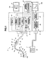
Fig. 1 is a diagram illustrating an example of a configuration of main parts of an endoscope system according to an embodiment of the present invention; -
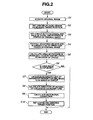
Fig. 2 is a diagram illustrating an example of processing performed to set a bending target position; -
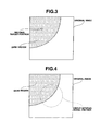
Fig. 3 is a diagram illustrating an example of a bending target position in an original image; -
Fig. 4 is a diagram illustrating an example where a circle imitating the distal end face of the distal end portion of the endoscope is set in an original image; -
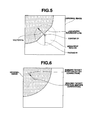
Fig. 5 is a diagram illustrating an example of a vector for correcting the bending target position; -
Fig. 6 is a diagram illustrating an example where the bending target position inFig. 3 is corrected to a new bending target position; -
Fig. 7 is a diagram illustrating a first modification example of the processing performed to set a bending target position; -
Fig. 8 is a diagram illustrating a second modification example of the processing performed to set a bending target position; -
Fig. 9 is a diagram illustrating a third modification example of the processing performed to set a bending target position; -
Fig. 10 is a diagram illustrating an example where a circle imitating the distal end face of the distal end portion of the endoscope is set in an original image and a portion including the interior and boundary of the circle is divided into a plurality of small regions; and -
Fig. 11 is a diagram illustrating an example of a route acquired when a gradient direction from a bright region toward a dark region is sequentially traced. - Hereinafter, an embodiment of the present invention will be described with reference to the accompanying drawings.
-
Fig. 1 to Fig. 11 are related to the embodiment of the present invention.Fig. 1 is a diagram illustrating an example of a configuration of main parts of an endoscope system according to an embodiment of the present invention.Fig. 2 is a diagram illustrating an example of processing performed to set a bending target position.Fig. 3 is a diagram illustrating an example of a bending target position in an original image.Fig. 4 is a diagram illustrating an example where a circle imitating the distal end face of the distal end portion of the endoscope is set in an original image.Fig. 5 is a diagram illustrating a vector for correcting the bending target position obtained in the processing inFig. 2 .Fig. 6 is a diagram illustrating an example where the bending target position inFig. 3 is corrected to a new bending target position.Fig. 7 is a diagram illustrating a first modification example of the processing performed to set a bending target position.Fig. 8 is a diagram illustrating a second modification example of the processing performed to set a bending target position.Fig. 9 is a diagram illustrating a third modification example of the processing performed to set a bending target position.Fig. 10 is a diagram illustrating an example where a circle imitating the distal end face of the distal end portion of the endoscope is set in an original image and a portion including the interior and boundary of the circle is divided into a plurality of small regions.Fig. 11 is a diagram illustrating an example of a route acquired when a gradient direction from a bright region toward a dark region is sequentially traced. - As shown in
Fig. 1 , anendoscope system 1 is configured by including anendoscope 2 inserted into a body cavity of a patient as an object to be examined to pick up an image of the object in the body cavity, aprocessor 6 to/from which aconnector 14 provided in theendoscope 2 can be attached/detached, asense coil unit 7 disposed in a periphery of a bed on which the patient lies, an endoscope insertion shape detection apparatus 8, aterminal apparatus 9 andmonitors - Furthermore, the
processor 6 includes alight source section 3 that supplies illumination light for illuminating an object which becomes an image pickup target to theendoscope 2, a signal processing section 4 that performs signal processing on an image pickup signal outputted from theendoscope 2 and thereby generates and outputs a video signal, abending control section 5 that performs bending control on theendoscope 2 and a sourcecoil drive section 43. - The
endoscope 2 includes anelongated insertion portion 11 inserted into the body cavity of the object to be examined, anoperation section 12 provided at a rear end of theinsertion portion 11 and auniversal cord 13 that extends out from theoperation section 12. Theconnector 14 attachable/detachable to/from theprocessor 6 is provided at a rear end of theuniversal cord 13. - The
insertion portion 11 includes a rigiddistal end portion 15 provided at a distal end, abending portion 16 connected at a rear end of thedistal end portion 15 and aflexible tube portion 17 having flexibility provided between a rear end of thebending portion 16 and a front end of theoperation section 12. Furthermore, n source coils C1, C2, ..., Cn that generate magnetic fields corresponding to a source coil drive signal applied from the sourcecoil drive section 43 are provided at substantially equal intervals inside theinsertion portion 11. - The
distal end portion 15 is configured by including a circular distal end face. Furthermore, animage pickup section 15a provided with an objective optical system that forms an image of an object and an image pickup device that outputs the image of the object formed through the objective optical system as an image pickup signal or the like is provided at thedistal end portion 15. - The
operation section 12 is provided with ascope switch 18 that instructs acquisition of a freeze image (still image) or the like, a bendingmode changeover switch 19 that instructs changeover of the bending mode of thebending portion 16 to a manual mode or an automatic mode and abending joystick 20 that instructs, when the manual mode is selected, a bending direction and a bending angle of thebending portion 16. Furthermore, a treatmentinstrument insertion port 39 through which a treatment instrument or the like can be inserted and which leads to a channel (not shown) for the treatment instrument is provided at a portion on the rear end side of theflexible tube portion 17 and near the front end of theoperation section 12. - A
light guide 21 that transmits illumination light supplied from thelight source section 3 to thedistal end portion 15 is inserted into theinsertion portion 11 or the like of theendoscope 2. - One end face (incident end face) of the
light guide 21 is disposed protruding from theconnector 14. On the other hand, the other end face (outgoing end face) of thelight guide 21 is disposed in the vicinity of an illumination optical system (not shown) provided at thedistal end portion 15. In such a configuration, when theconnector 14 is connected to theprocessor 6, the illumination light supplied from thelight source section 3 passes through thelight guide 21 and an illumination optical system (not shown) and illuminates the object which is the image pickup target of theimage pickup section 15a. - The
light source section 3 provided with the function as a light source apparatus includes alamp 22 that emits illumination light which is, for example, white color light, alamp drive section 23 that supplies power necessary to drive thelamp 22, adiaphragm 24, adiaphragm control section 25 that increases/decreases the amount of diaphragm (amount of aperture) of thediaphragm 24 based on a video signal outputted from the signal processing section 4 and a condensingoptical system 26 that supplies the illumination light to the incident end face of thelight guide 21 while condensing the illumination light that has passed through thediaphragm 24. - The
diaphragm control section 25 calculates average brightness based on, for example, the luminance component of a video signal inputted, increases/decreases the amount of diaphragm (amount of aperture) of thediaphragm 24 based on a difference value which is a value obtained by subtracting a reference value corresponding to appropriate brightness from the average brightness and thereby changes the light amount of the illumination light that passes through thediaphragm 24 as appropriate. - The signal processing section 4 includes an image pickup
device drive section 36 that outputs an image pickup device drive signal to drive an image pickup device provided in theimage pickup section 15a and avideo processing section 37 that generates and outputs a video signal by applying signal processing to the image pickup signal outputted from theimage pickup section 15a. In this way, themonitor 10a displays an endoscope image Ia corresponding to the video signal. - When the bending mode of the
bending portion 16 is changed to a manual mode based on an instruction given by the bendingmode changeover switch 19, thebending control section 5 performs control to change the direction of bending and the angle of bending of thebending portion 16 based on the direction of inclination and the amount of inclination of thebending joystick 20. Furthermore, when the bending mode of thebending portion 16 is changed to an automatic mode based on an instruction given by the bendingmode changeover switch 19, thebending control section 5 performs control to change the direction of bending and the angle of bending of thebending portion 16 based on the calculation result of theterminal apparatus 9. - The source
coil drive section 43 is connected to the n source coils C1, C2, ..., Cn provided inside theinsertion portion 11 and sequentially applies AC source coil drive signals to the respective source coils. Thus, an AC magnetic field is generated around each source coil provided inside theinsertion portion 11. - The
sense coil unit 7 is provided with asense coil group 44 that detects magnetic fields emitted from the n source coils C1, C2, ..., Cn provided inside theinsertion portion 11 and outputs the detected values as magnetic field detection signals. - The endoscope insertion shape detection apparatus 8 includes an
amplifier 45 that amplifies the magnetic field detection signals outputted from thesense coil unit 7, a source coil position/orientation detection section 46 that detects three-dimensional coordinate positions and orientations of the n source coils C1, C2, ..., Cn based on the magnetic field detection signals outputted from theamplifier 45 and outputs the detected values as insertion shape information and an insertionshape estimation section 47 that estimates an insertion shape of theinsertion portion 11 based on the insertion shape information outputted from the source coil position/orientation detection section 46 and outputs the estimated value as an insertion shape image signal. In this way, themonitor 10b displays an insertion shape image Ib of theinsertion portion 11 corresponding to the insertion shape image signal. - The
terminal apparatus 9 includes acalculation processing section 91 that carries out a calculation on bending control performed when the bending mode of the bendingportion 16 is an automatic mode based on the video signal outputted from thevideo processing section 37 and the insertion shape information outputted from the source coil position/orientation detection section 46 and outputs the calculation result to the bendingcontrol section 5. More specific contents of the calculation performed by thecalculation processing section 91 will be described later. - Furthermore, the
terminal apparatus 9 is provided with a memory (not shown) that can temporarily store the calculation result or the like of thecalculation processing section 91. - Next, operations bf the
endoscope system 1 will be described. Hereinafter, suppose descriptions of the control when the bendingmode changeover switch 19 is changed to the manual bending mode will be omitted and descriptions will be focused on the control when the bendingmode changeover switch 19 is changed to the automatic bending mode. - The operator connects and starts each section of the
endoscope system 1 first, and then inserts theinsertion portion 11 of theendoscope 2 into the body cavity of the patient and changes the bendingmode changeover switch 19 to the automatic bending mode. Accordingly, image pickup of the object by theimage pickup section 15a of theendoscope 2 starts and each source coil provided in theinsertion portion 11 starts to generate a magnetic field. - An image pickup signal outputted from the
image pickup section 15a along with image pickup of the object is outputted to theprocessor 6 through theuniversal cord 13 and theconnector 14, converted to a video signal by thevideo processing section 37 and then inputted to thecalculation processing section 91 of theterminal apparatus 9. On the other hand, a magnetic field detection signal outputted from thesense coil unit 7 along with generation of the magnetic field in each source coil provided in theinsertion portion 11 is amplified by theamplifier 45, converted as three-dimensional coordinate information of the source coil by the source coil position/orientation detection section 46, an insertion shape thereof is estimated by the insertionshape estimation section 47, and then inputted to thecalculation processing section 91 of theterminal apparatus 9 as an insertion shape image signal. - The
calculation processing section 91 of theterminal apparatus 9 performs processing based on the inputted video signal and insertion shape image signal or the like, thereby sets a bending target position (passage target position) which becomes a passage target of thedistal end portion 15 and outputs information on the set bending target position to the bendingcontrol section 5. - Here, the processing performed by the
calculation processing section 91 when setting the aforementioned bending target position will be described. - First, the
calculation processing section 91 acquires an original image corresponding to an inputted video signal (step S1 inFig. 2 ). - Next, the
calculation processing section 91 provided with the function as a position setting section extracts a dark region in the original image acquired in step S1 inFig. 2 and then sets the center of the dark region as a bending target position (passage target position of the distal end portion 15) of the bendingportion 16 by using publicly known processing (step S2 inFig. 2 ). Through such processing, a pixel position in the original image as shown, for example, inFig. 3 is set as a bending target position. - Furthermore, the
calculation processing section 91 sets a circle imitating the distal end face of thedistal end portion 15 in the center of the acquired original image (step S3 inFig. 2 ) and then extracts the brightest region and a boundary line of the brightest region in the original image (step S4 inFig. 2 ). The circle imitating the distal end face of thedistal end portion 15 is as shown, for example, inFig. 4 . - Here, a more specific example of the processing performed to extract the brightest region will be described.
- First, the
calculation processing section 91 divides the original image into a plurality of equally spaced rectangular regions, identifies one pixel corresponding to the center of gravity of the rectangular region having the highest average of pixel values, and then compares pixel values of four nearby pixels neighboring the one pixel with a predetermined threshold. - Next, while regarding pixels provided with pixel values equal to or above the predetermined threshold as pixels that belong to the brightest region, the
calculation processing section 91 compares pixel values of four neighboring pixels of each pixel which has newly come to belong to the brightest region with a predetermined threshold. - By repeatedly performing the aforementioned comparison processing until no pixel regarded as belonging to the brightest region is left, it is possible to obtain extraction results of the brightest region and the boundary line of the brightest region.
- On the other hand, the
calculation processing section 91 calculates the area of the portion of the brightest region extracted in step S4 inFig. 2 that belongs to the interior of the circle set in step S3 inFig. 2 (step S5 inFig. 2 ). - After that, the
calculation processing section 91 judges whether the ratio of the area of the brightest region inside the circle to the area of the entire circle set in step S3 inFig. 2 is 0.2 or more (step S6 inFig. 2 ). Upon detecting that the area ratio is less than 0.2, thecalculation processing section 91 considers it unnecessary to correct the bending target position calculated in step S2 inFig. 2 and outputs the calculation result of the bending target position to the bendingcontrol section 5. Furthermore, upon detecting that the area ratio is 0.2 or above, thecalculation processing section 91 considers it necessary to correct the bending target position calculated in step S2 inFig. 2 and continues to perform processing from step S7 inFig. 2 onward. - The
calculation processing section 91 performs processing such as a Hough transform and thereby linearizes the boundary line in the brightest region that belongs to the interior of the circle set in step S3 inFig. 2 (step S7 inFig. 2 ). - Furthermore, the
calculation processing section 91 calculates the direction of the normal to the boundary line linearized in step S7 inFig. 2 (step S8 inFig. 2 ). To be more specific, thecalculation processing section 91 calculates a direction opposite to the direction in which the center of gravity of the brightest region that belongs to the interior of the circle exists as the direction of the normal to the boundary line linearized in step S7 inFig. 2 . - Next, the
calculation processing section 91 calculates a vector for correcting the bending target position Va having a center D1 of the circle set in step S3 inFig. 2 as a starting point, having the same size as a radius R1 of the circle and oriented toward the same direction as the direction of the normal calculated in step S8 in Fig. - 2 as a vector as shown, for example, in
Fig. 5 (step S9 inFig. 2 ). Furthermore, before and after the processing in step S9 inFig. 2 , thecalculation processing section 91 performs processing of calculating a vector Vb, the starting point of which is the center D1 of the circle set in step S3 inFig. 2 and the end point of which is the bending target position calculated in step S2 inFig. 2 . - The
calculation processing section 91 provided with the function as a position correction section generates a combined vector obtained by adding up the aforementioned vectors Va and Vb at a first ratio and then sets the pixel position which corresponds to the end point of the combined vector as the corrected bending target position (step S10 inFig. 2 ). Through such processing, the bending target position calculated in step S2 inFig. 2 is corrected to a new bending target position as shown, for example, inFig. 6 . - After that, the
calculation processing section 91 outputs the calculation result of the corrected bending target position obtained in step S10 inFig. 2 to the bendingcontrol section 5. - The bending
control section 5 then performs control based on the processing result of the series of processes shown inFig. 2 , and can thereby bend the bendingportion 16 so as to avoid contact of the distal end face of thedistal end portion 15 with the fold or body wall in the body cavity as much as possible. - According to the present embodiment, as shown, for example, in the following modification examples, it is also possible to correct the bending target position using the extraction result of the dark region in the original image and elements other than the extraction result of the brightest region in the original image.
- Here, as a first modification example of the present embodiment, a series of processes performed to correct the bending target position using an extraction result of a dark region in an original image and an extraction result of an edge in the original image will be described with reference to
Fig. 7 . - First, the
calculation processing section 91 acquires an original image corresponding to an inputted video signal (step S21Fig. 7 ). - Next, the
calculation processing section 91 extracts a dark region in the original image acquired in step S21 inFig. 7 , and then sets the center of the dark region as a bending target position of the bending portion 16 (passage target position of the distal end portion 15) using publicly known processing (step S22 inFig. 7 ). - Furthermore, the
calculation processing section 91 sets a circle imitating the distal end face of thedistal end portion 15 in the center of the acquired original image (step S23 inFig. 7 ) and then extracts an edge included in the circle (step S24 inFig. 7 ). - After that, the
calculation processing section 91 calculates the direction of the normal to the edge extracted in step S24 inFig. 7 (step S25 inFig. 7 ). To be more specific, thecalculation processing section 91 calculates such a direction that the angle formed with a vector oriented from the center of the edge toward the bending target position is less than 90° as the direction of the normal of the edge. - Next, the
calculation processing section 91 calculates a vector for correcting the bending target position Vc having a center D2 of the circle set in step S23 inFig. 7 as a starting point, having the same size as the radius R2 of the circle and oriented in the same direction as the direction of the normal calculated in step S25 inFig. 7 (step S26 inFig. 7 ). Furthermore, before and after the processing in step S26 inFig. 7 , thecalculation processing section 91 performs processing of calculating a vector Vd, the starting point of which is the center D2 of the circle set in step S23 inFig. 7 and the end point of which is the bending target position calculated in step S22 inFig. 7 . - The
calculation processing section 91 generates a combined vector obtained by adding up the aforementioned vectors Vc and Vd at a second ratio and then sets a pixel position which corresponds to the end point of the combined vector as the corrected bending target position (step S27 inFig. 7 ). Through such processing, the bending target position calculated in step S22 inFig. 7 is corrected to a new bending target position. - After that, the
calculation processing section 91 outputs the calculation result of the corrected bending target position obtained in step S27 inFig. 7 to the bendingcontrol section 5. - The bending
control section 5 then performs control based on the processing result of the series of processes shown inFig. 7 , and can thereby bend the bendingportion 16 so as to avoid contact of the distal end face of thedistal end portion 15 with the fold or body wall in the body cavity as much as possible. - Here, as a second modification example of the present embodiment, a series of processes performed to correct the bending target position using the extraction result of the dark region in the original image and the extraction result of color tone in the original image will be described with reference to
Fig. 8 . - First, the
calculation processing section 91 acquires an original image corresponding to an inputted video signal (step S41 inFig. 8 ). - Next, the
calculation processing section 91 extracts a dark region in the original image acquired in step S41 inFig. 8 and then sets the center of the dark region as a bending target position of the bending portion 16 (passage target position of the distal end portion 15) using publicly known processing (step S42 inFig. 8 ). - Furthermore, the
calculation processing section 91 sets a circle imitating the distal end face of thedistal end portion 15 in the center of the acquired original image (step S43 inFig. 8 ), then connects and paints proximity pixels having similar color tones in the original image and thereby divides the original image into a plurality of small regions (step S44 inFig. 8 ). Suppose thecalculation processing section 91 performs processing using a watershed algorithm or segmentation algorithm based on an image pyramid or the like as the processing in step S44 inFig. 8 . - The
calculation processing section 91 detects a color tone of a small region having a portion overlapping with the interior of the circle set in step S43 inFig. 8 out of the plurality of small regions obtained in step S44 inFig. 8 (step S45 inFig. 8 ). - After that, the
calculation processing section 91 judges whether or not the small region is a region showing a residue based on the color tone of the small region detected in step S45 inFig. 8 (step S46 inFig. 8 ). - Here, a specific example of the processing performed to judge whether or not the small region is a region showing a residue based on the color tone will be described.
- First, the
calculation processing section 91 converts RGB values of the small region detected in step S45 inFig. 8 to chromaticity coordinates (x, y) using publicly known processing. - Next, the
calculation processing section 91 judges whether or not the obtained chromaticity coordinates (x, y) satisfy the relationship in Expression (1) below in a CIExy chromaticity diagram.
- When the obtained chromaticity coordinates (x, y) do not satisfy the relationship in Expression (1) above, the
calculation processing section 91 judges that the small region detected in step S45 inFig. 8 shows an element (blood or the like) other than the residue, and also considers it unnecessary to correct the bending target position calculated in step S42 inFig. 8 and outputs the calculation result of the bending target position to the bendingcontrol section 5. On the other hand, when the obtained chromaticity coordinates (x, y) satisfy the relationship in Expression (1) above, thecalculation processing section 91 judges that the small region detected in step S45 inFig. 8 shows a residue, considers it necessary to correct the bending target position calculated in step S42 inFig. 8 and continues to perform processing from step S47 inFig. 8 onward. - After that, the
calculation processing section 91 approximates the small region judged to show the residue with an ellipse (step S47 inFig. 8 ). - Based on the ellipse obtained in step S47 in
Fig. 8 , thecalculation processing section 91 calculates two tangent vectors Vel and Ve2, the starting point of which is the center of the original image and the end point of which is a contact in the ellipse. Furthermore, thecalculation processing section 91 calculates a vector Vf, the starting point of which is a center D3 of the circle set in step S43 inFig. 8 and the end point of which is the bending target position calculated in step S42 inFig. 8 . - Of the two tangent vectors Ve1 and Ve2, the
calculation processing section 91 calculates one tangent vector having a relatively small angle formed with the vector Vf as a vector for correcting the bending target position (step S48 inFig. 8 ). - The
calculation processing section 91 generates a combined vector obtained by adding up the aforementioned one tangent vector (Ve1 or Ve2) and vector Vf at a third ratio and sets the pixel position which corresponds to the end point of the combined vector as a corrected bending target position (step S49 inFig. 8 ). Through such processing, the bending target position calculated in step S42 inFig. 8 is corrected to a new bending target position. - After that, the
calculation processing section 91 outputs the calculation result of the corrected bending target position obtained in step S49 inFig. 8 to the bendingcontrol section 5. - The bending
control section 5 then performs control based on the processing result of the series of processes shown inFig. 8 and can thereby bend the bendingportion 16 so as to avoid contact of the distal end face of thedistal end portion 15 with the residue existing in the body cavity as much as possible. - Here, as a third modification example of the present embodiment, a series of processes performed to correct the bending target position using the extraction result of the dark region in the original image and the extraction result of a gradient of pixel values in the original image will be described with reference to
Fig. 9 or the like. - First, the
calculation processing section 91 acquires an original image corresponding to an inputted video signal (step S61 inFig. 9 ). - Next, the
calculation processing section 91 extracts a dark region in the original image acquired in step S61 inFig. 9 and then sets the center of the dark region as a bending target position of the bending portion 16 (passage target position of the distal end portion 15) using publicly known processing (step S62 inFig. 9 ). - Furthermore, the
calculation processing section 91 sets a circle imitating the distal end face of thedistal end portion 15 in the center of the acquired original image (step S63 inFig. 9 ) and then divides the portion including the interior and a boundary of the circle into a plurality of small rectangular regions (step S64 inFig. 9 ). To be more specific, the circle set in step S63 inFig. 9 is divided into a plurality of small regions as shown, for example, inFig. 10 through the processing in step S64 inFig. 9 . - Next, the
calculation processing section 91 calculates an average of pixel values in each small region obtained in step S64 inFig. 9 (step S65 inFig. 9 ). - Furthermore, the
calculation processing section 91 detects a gradient direction from the bright region toward the dark region for each small region using the average of pixel values in each small region calculated through the processing in step S65 inFig. 9 (step S66 inFig. 9 ). To be more specific, thecalculation processing section 91 compares the average of pixel values in one small region with averages of pixel values in eight small regions in the vicinity of the one small region respectively and detects a direction in which small regions exist whose average of pixel values is lower than the one small region out of the eight nearby small regions as the aforementioned gradient direction (for each region). - On the other hand, the
calculation processing section 91 sequentially traces the gradient directions detected in step S66 inFig. 9 and thereby acquires a route from the small region including the center of the circle set in step S63 inFig. 9 to the small region near the boundary of the circle. The route is acquired as shown, for example, inFig. 11 . - The
calculation processing section 91 then calculates a vector for correcting the bending target position Vg, the starting point of which is a center D4 of the circle set in step S63 inFig. 9 , having the same size as a radius R4 of the circle, oriented toward the same direction as the gradient direction in a small region including the start point of the route or the gradient direction in a small region including the end point of the route (step S67 inFig. 9 ). Furthermore, before and after the processing in step S67 inFig. 9 , thecalculation processing section 91 performs processing of calculating a vector Vh, the starting point of which is the center D4 of the circle set in step S63 inFig. 9 and the end point of which is the bending target position calculated in step S62 inFig. 9 . - The
calculation processing section 91 generates a combined vector obtained by adding up the aforementioned vectors Vg and Vh at a fourth ratio and then sets a pixel position corresponding to the end point of the combined vector as a corrected bending target position (step S68 inFig. 9 ). Through such processing, the bending target position calculated in step S62 inFig. 9 is corrected to a new bending target position. - After that, the
calculation processing section 91 outputs the calculation result of the corrected bending target position obtained in step S68 inFig. 9 to the bendingcontrol section 5. - The bending
control section 5 then performs control based on the processing result of the series of processes shown inFig. 9 , and can thereby bend the bendingportion 16 so as to avoid contact of the distal end face of thedistal end portion 15 with the fold or body wall existing in the body cavity as much as possible. - As described above, the
endoscope system 1 of the present embodiment performs a calculation using the extraction result of the dark region in the original image and image elements other than the extraction result of the dark region in the original image, and can thereby set an appropriate bending target position (passage target position) such that the distal end face of thedistal end portion 15 does not contact an object existing in the insertion direction of theendoscope 2. Therefore, theendoscope system 1 of the present embodiment can insert the endoscope more smoothly than conventional ones. - On the other hand, in addition to the case where a preset one bending target position is corrected and the bending portion is bent according to another corrected bending target position, the present embodiment may also include an application example where, for example, a preset one image pickup target position is corrected and the image pickup state of the image pickup section is adjusted according to another corrected image pickup target position.
- To be more specific, examples of the configuration corresponding to the aforementioned application example include a configuration where the objective optical system of the
image pickup section 15a includes a zoom lens and theprocessor 6 includes a lens drive control section to drive the zoom lens. - Furthermore, as an operation corresponding to the aforementioned configuration, the
calculation processing section 91 performs processing of setting one image pickup target position based on one piece of information (information on the dark region) obtained from the image of the object picked up by theimage pickup section 15a and then calculating another image pickup target position, which is different from the one image pickup target position based on other information (information on any one of the bright region, edge, color tone and gradient of the pixel value) obtained from the image. Furthermore, following the above described processing, when the other image pickup target position is outside the image (outside the range of the observation field of view of theimage pickup section 15a), the lens drive control section performs control so as to drive the zoom lens of theimage pickup section 15a to the wide-angle side. - When an application example provided with the above described configuration and operation is executed, it is possible to obtain an effect of being able to insert the endoscope more smoothly than conventional ones.
- The present invention is not limited to the aforementioned embodiment, but it goes without saying that the present invention can be modified or applied in various ways without departing from the spirit and scope of the invention.
- The present application is filed claiming the priority of Japanese Patent Application No.
2009-018485
Claims (10)
- An endoscope system comprising:an endoscope provided with an image pickup section that picks up an image of an object in a body cavity;a position setting section that sets one position in the image based on one piece of information obtained from the image of the object; anda position correction section that corrects the one position set by the position setting section based on other information obtained from the image, to thereby set another position different from the one position.
- An endoscope system comprising:an endoscope provided with an image pickup section that picks up an image of an object in a body cavity;a position setting section that sets one position in the image based on one piece of information obtained from the image of the object;a position correction section that corrects the one position set by the position setting section based on other information obtained from the image, to thereby set another position different from the one position; andan image pickup state adjusting section that adjusts an image pickup state of the image pickup section based on information on the other position set by the position correction section.
- An endoscope system comprising:an endoscope provided with an insertion portion to be inserted into a body cavity, an image pickup section provided at a distal end portion of the insertion portion, and a bending portion that bends the insertion portion;a position setting section that sets, based on one piece of information obtained from an image of an object picked up by the image pickup section, one target position through which the distal end portion is made to pass in the image;a position correction section that corrects the one target position set by the position setting section based on other information obtained from the image, to thereby set in the image another target position different from the one target position; anda bending control section that performs control to bend the bending portion based on information on the other target position set by the position correction section.
- The endoscope system according to any one of claims 1 to 3, wherein the one piece of information is information on a dark region of the image.
- The endoscope system according to any one of claims 1 to 3, wherein the other information is information on a bright region of the image.
- The endoscope system according to any one of claims 1 to 3, wherein the other information is information on an edge of the image.
- The endoscope system according to any one of claims 1 to 3, wherein the other information is information on a color tone of the image.
- The endoscope system according to any one of claims 1 to 3, wherein the other information is information on a gradient of pixel values of the image.
- The endoscope system according to claim 4, wherein the other information is any one of information on a bright region of the image, information on an edge of the image, information on a color tone of the image and information on a gradient of pixel values of the image.
- An endoscope system comprising:an endoscope provided with an insertion portion to be inserted into a body cavity, an image pickup section provided at a distal end portion of the insertion portion, and a bending portion that bends the insertion portion;a position setting section that sets one target position through which the distal end portion is made to pass in an image of an object picked up by the image pickup section;a position correction section that corrects the one target position set by the position setting section based on information on a bright region of the image, to thereby set in the image another target position different from the one target position; anda bending control section that performs control to bend the bending portion based on information on the other target position set by the position correction section.
Applications Claiming Priority (2)
| Application Number | Priority Date | Filing Date | Title |
|---|---|---|---|
| JP2009018485 | 2009-01-29 | ||
| PCT/JP2009/067554 WO2010087057A1 (en) | 2009-01-29 | 2009-10-08 | Endoscope system |
Publications (2)
| Publication Number | Publication Date |
|---|---|
| EP2382909A1 true EP2382909A1 (en) | 2011-11-02 |
| EP2382909A4 EP2382909A4 (en) | 2012-11-28 |
Family
ID=42395325
Family Applications (1)
| Application Number | Title | Priority Date | Filing Date |
|---|---|---|---|
| EP09839246A Withdrawn EP2382909A4 (en) | 2009-01-29 | 2009-10-08 | Endoscope system |
Country Status (5)
| Country | Link |
|---|---|
| US (1) | US8167792B2 (en) |
| EP (1) | EP2382909A4 (en) |
| JP (1) | JP4624486B2 (en) |
| CN (1) | CN102123650B (en) |
| WO (1) | WO2010087057A1 (en) |
Cited By (1)
| Publication number | Priority date | Publication date | Assignee | Title |
|---|---|---|---|---|
| CN104361608A (en) * | 2014-10-27 | 2015-02-18 | 浙江大学宁波理工学院 | Positioning and tracking method for industrial flexible catheter endoscope |
Families Citing this family (8)
| Publication number | Priority date | Publication date | Assignee | Title |
|---|---|---|---|---|
| JP2011237525A (en) * | 2010-05-07 | 2011-11-24 | Olympus Corp | Imaging module |
| JP5663283B2 (en) * | 2010-12-02 | 2015-02-04 | オリンパス株式会社 | Endoscopic image processing apparatus and program |
| CN102631178A (en) * | 2012-05-15 | 2012-08-15 | 重庆大学 | Micro-traumatic superfine endoscope system |
| CN106371374A (en) * | 2016-11-07 | 2017-02-01 | 福州幻科机电科技有限公司 | Intelligent control circuit system for minimally invasive endoscopic four-freedom-degree locator |
| WO2018154824A1 (en) * | 2017-02-22 | 2018-08-30 | オリンパス株式会社 | Endoscope operation unit and endoscope including same |
| WO2021048925A1 (en) * | 2019-09-10 | 2021-03-18 | オリンパス株式会社 | Endoscope control device, method for operating endoscope control device, and program |
| US11445108B1 (en) * | 2021-03-05 | 2022-09-13 | International Business Machines Corporation | Turn direction guidance of an endoscopic device |
| CN115553689B (en) * | 2022-10-25 | 2023-09-26 | 深圳市星辰海医疗科技有限公司 | Endoscope handle |
Citations (3)
| Publication number | Priority date | Publication date | Assignee | Title |
|---|---|---|---|---|
| US5018509A (en) * | 1989-02-21 | 1991-05-28 | Olympus Optical Co., Ltd. | Endoscope insertion controlling apparatus |
| WO2008155828A1 (en) * | 2007-06-20 | 2008-12-24 | Olympus Medical Systems Corp. | Endoscope system, imaging system, and image processing device |
| EP2215960A1 (en) * | 2007-11-29 | 2010-08-11 | Olympus Medical Systems Corp. | Endoscope curve control device and endoscope system |
Family Cites Families (17)
| Publication number | Priority date | Publication date | Assignee | Title |
|---|---|---|---|---|
| GB2225188B (en) * | 1988-11-16 | 1993-05-12 | Olympus Optical Co | Methods of detecting endoscope insertion direction |
| GB8830465D0 (en) * | 1988-12-31 | 1989-03-01 | Olympus Optical Co | Methods of detecting endoscope insertion direction |
| GB2238440B (en) * | 1989-11-24 | 1994-07-27 | Olympus Optical Co | Methods of detecting endoscope insertion direction |
| US5347987A (en) * | 1991-04-08 | 1994-09-20 | Feldstein David A | Self-centering endoscope system |
| US5469840A (en) * | 1991-12-10 | 1995-11-28 | Olympus Optical, Ltd. | Electromotive warping type endoscope with velocity control |
| US5658238A (en) * | 1992-02-25 | 1997-08-19 | Olympus Optical Co., Ltd. | Endoscope apparatus capable of being switched to a mode in which a curvature operating lever is returned and to a mode in which the curvature operating lever is not returned |
| JP3179167B2 (en) * | 1992-02-25 | 2001-06-25 | オリンパス光学工業株式会社 | Endoscope device |
| US5469254A (en) * | 1992-04-06 | 1995-11-21 | Olympus Optical Co., Ltd. | Method and apparatus for measuring three-dimensional position of a pipe from image of the pipe in an endoscopic observation system |
| JP3523672B2 (en) | 1993-12-02 | 2004-04-26 | オリンパス株式会社 | Endoscope device |
| JP4885388B2 (en) * | 2001-09-25 | 2012-02-29 | オリンパス株式会社 | Endoscope insertion direction detection method |
| US6770027B2 (en) | 2001-10-05 | 2004-08-03 | Scimed Life Systems, Inc. | Robotic endoscope with wireless interface |
| US6835173B2 (en) | 2001-10-05 | 2004-12-28 | Scimed Life Systems, Inc. | Robotic endoscope |
| JP4077716B2 (en) * | 2002-11-20 | 2008-04-23 | オリンパス株式会社 | Endoscope insertion direction detection device |
| JP4695420B2 (en) * | 2004-09-27 | 2011-06-08 | オリンパス株式会社 | Bending control device |
| CN101065052B (en) * | 2004-12-27 | 2010-12-22 | 奥林巴斯株式会社 | Medical image processing device and method |
| JP5094036B2 (en) * | 2006-04-17 | 2012-12-12 | オリンパスメディカルシステムズ株式会社 | Endoscope insertion direction detection device |
| JP2009018485A (en) | 2007-07-11 | 2009-01-29 | Niigata Machine Techno Co Ltd | Injection molding method and injection molding device |
-
2009
- 2009-10-08 CN CN200980131439.5A patent/CN102123650B/en active Active
- 2009-10-08 EP EP09839246A patent/EP2382909A4/en not_active Withdrawn
- 2009-10-08 JP JP2010518441A patent/JP4624486B2/en active Active
- 2009-10-08 WO PCT/JP2009/067554 patent/WO2010087057A1/en active Application Filing
-
2010
- 2010-05-19 US US12/783,040 patent/US8167792B2/en active Active
Patent Citations (3)
| Publication number | Priority date | Publication date | Assignee | Title |
|---|---|---|---|---|
| US5018509A (en) * | 1989-02-21 | 1991-05-28 | Olympus Optical Co., Ltd. | Endoscope insertion controlling apparatus |
| WO2008155828A1 (en) * | 2007-06-20 | 2008-12-24 | Olympus Medical Systems Corp. | Endoscope system, imaging system, and image processing device |
| EP2215960A1 (en) * | 2007-11-29 | 2010-08-11 | Olympus Medical Systems Corp. | Endoscope curve control device and endoscope system |
Non-Patent Citations (1)
| Title |
|---|
| See also references of WO2010087057A1 * |
Cited By (2)
| Publication number | Priority date | Publication date | Assignee | Title |
|---|---|---|---|---|
| CN104361608A (en) * | 2014-10-27 | 2015-02-18 | 浙江大学宁波理工学院 | Positioning and tracking method for industrial flexible catheter endoscope |
| CN104361608B (en) * | 2014-10-27 | 2017-02-01 | 浙江大学宁波理工学院 | Positioning and tracking method for industrial flexible catheter endoscope |
Also Published As
| Publication number | Publication date |
|---|---|
| JPWO2010087057A1 (en) | 2012-07-26 |
| US20100283841A1 (en) | 2010-11-11 |
| JP4624486B2 (en) | 2011-02-02 |
| WO2010087057A1 (en) | 2010-08-05 |
| US8167792B2 (en) | 2012-05-01 |
| CN102123650B (en) | 2014-04-16 |
| EP2382909A4 (en) | 2012-11-28 |
| CN102123650A (en) | 2011-07-13 |
Similar Documents
| Publication | Publication Date | Title |
|---|---|---|
| US8167792B2 (en) | Endoscope system having passage position setting section and passage position correction section | |
| EP2301411B1 (en) | Endoscope system | |
| US8147402B2 (en) | Endoscope system | |
| EP2215960B1 (en) | Endoscope curve control apparatus | |
| EP2289390B1 (en) | Detection of endoscope inserting direction | |
| EP2767857A1 (en) | Focus control device, endoscope system and focus control method | |
| US10413157B2 (en) | Endoscope system with image pasting on planar model | |
| EP2425760A1 (en) | Endoscope system | |
| JP7385731B2 (en) | Endoscope system, image processing device operating method, and endoscope | |
| JP2006223850A (en) | Electronic endoscope system | |
| US11483473B2 (en) | Surgical image processing apparatus, image processing method, and surgery system | |
| WO2020231157A1 (en) | Augmented reality colonofiberscope system and monitoring method using same | |
| JP5530406B2 (en) | Method of operating endoscope insertion direction detection device and endoscope insertion direction detection device | |
| JP2011235176A (en) | Method and device for detecting insertion direction of endoscope | |
| US10653305B2 (en) | Image processing system and endoscope using the same | |
| CN102631178A (en) | Micro-traumatic superfine endoscope system |
Legal Events
| Date | Code | Title | Description |
|---|---|---|---|
| PUAI | Public reference made under article 153(3) epc to a published international application that has entered the european phase |
Free format text: ORIGINAL CODE: 0009012 |
|
| 17P | Request for examination filed |
Effective date: 20110113 |
|
| AK | Designated contracting states |
Kind code of ref document: A1 Designated state(s): AT BE BG CH CY CZ DE DK EE ES FI FR GB GR HR HU IE IS IT LI LT LU LV MC MK MT NL NO PL PT RO SE SI SK SM TR |
|
| DAX | Request for extension of the european patent (deleted) | ||
| A4 | Supplementary search report drawn up and despatched |
Effective date: 20121026 |
|
| RIC1 | Information provided on ipc code assigned before grant |
Ipc: A61B 1/00 20060101AFI20121022BHEP Ipc: A61B 1/31 20060101ALI20121022BHEP Ipc: A61B 5/06 20060101ALI20121022BHEP Ipc: A61B 1/04 20060101ALI20121022BHEP Ipc: A61B 1/005 20060101ALI20121022BHEP Ipc: G02B 23/24 20060101ALI20121022BHEP |
|
| RAP1 | Party data changed (applicant data changed or rights of an application transferred) |
Owner name: OLYMPUS CORPORATION |
|
| RAP1 | Party data changed (applicant data changed or rights of an application transferred) |
Owner name: OLYMPUS CORPORATION |
|
| RAP1 | Party data changed (applicant data changed or rights of an application transferred) |
Owner name: OLYMPUS CORPORATION |
|
| RIN1 | Information on inventor provided before grant (corrected) |
Inventor name: TANAKA, HIDEKI |
|
| STAA | Information on the status of an ep patent application or granted ep patent |
Free format text: STATUS: EXAMINATION IS IN PROGRESS |
|
| 17Q | First examination report despatched |
Effective date: 20170320 |
|
| STAA | Information on the status of an ep patent application or granted ep patent |
Free format text: STATUS: THE APPLICATION IS DEEMED TO BE WITHDRAWN |
|
| 18D | Application deemed to be withdrawn |
Effective date: 20180404 |