EP2382936A1 - Sealing plate having depressions with ceramic insulation - Google Patents
Sealing plate having depressions with ceramic insulation Download PDFInfo
- Publication number
- EP2382936A1 EP2382936A1 EP11164273A EP11164273A EP2382936A1 EP 2382936 A1 EP2382936 A1 EP 2382936A1 EP 11164273 A EP11164273 A EP 11164273A EP 11164273 A EP11164273 A EP 11164273A EP 2382936 A1 EP2382936 A1 EP 2382936A1
- Authority
- EP
- European Patent Office
- Prior art keywords
- depressions
- series
- sealing plate
- end effector
- opposing
- Prior art date
- Legal status (The legal status is an assumption and is not a legal conclusion. Google has not performed a legal analysis and makes no representation as to the accuracy of the status listed.)
- Granted
Links
Images


Classifications
-
- A—HUMAN NECESSITIES
- A61—MEDICAL OR VETERINARY SCIENCE; HYGIENE
- A61B—DIAGNOSIS; SURGERY; IDENTIFICATION
- A61B18/00—Surgical instruments, devices or methods for transferring non-mechanical forms of energy to or from the body
- A61B18/04—Surgical instruments, devices or methods for transferring non-mechanical forms of energy to or from the body by heating
- A61B18/12—Surgical instruments, devices or methods for transferring non-mechanical forms of energy to or from the body by heating by passing a current through the tissue to be heated, e.g. high-frequency current
- A61B18/14—Probes or electrodes therefor
- A61B18/1442—Probes having pivoting end effectors, e.g. forceps
- A61B18/1445—Probes having pivoting end effectors, e.g. forceps at the distal end of a shaft, e.g. forceps or scissors at the end of a rigid rod
-
- A—HUMAN NECESSITIES
- A61—MEDICAL OR VETERINARY SCIENCE; HYGIENE
- A61B—DIAGNOSIS; SURGERY; IDENTIFICATION
- A61B17/00—Surgical instruments, devices or methods, e.g. tourniquets
- A61B2017/00831—Material properties
- A61B2017/0088—Material properties ceramic
-
- A—HUMAN NECESSITIES
- A61—MEDICAL OR VETERINARY SCIENCE; HYGIENE
- A61B—DIAGNOSIS; SURGERY; IDENTIFICATION
- A61B18/00—Surgical instruments, devices or methods for transferring non-mechanical forms of energy to or from the body
- A61B2018/00053—Mechanical features of the instrument of device
- A61B2018/00107—Coatings on the energy applicator
-
- A—HUMAN NECESSITIES
- A61—MEDICAL OR VETERINARY SCIENCE; HYGIENE
- A61B—DIAGNOSIS; SURGERY; IDENTIFICATION
- A61B18/00—Surgical instruments, devices or methods for transferring non-mechanical forms of energy to or from the body
- A61B2018/00571—Surgical instruments, devices or methods for transferring non-mechanical forms of energy to or from the body for achieving a particular surgical effect
- A61B2018/0063—Sealing
-
- A—HUMAN NECESSITIES
- A61—MEDICAL OR VETERINARY SCIENCE; HYGIENE
- A61B—DIAGNOSIS; SURGERY; IDENTIFICATION
- A61B90/00—Instruments, implements or accessories specially adapted for surgery or diagnosis and not covered by any of the groups A61B1/00 - A61B50/00, e.g. for luxation treatment or for protecting wound edges
- A61B90/03—Automatic limiting or abutting means, e.g. for safety
- A61B2090/033—Abutting means, stops, e.g. abutting on tissue or skin
- A61B2090/034—Abutting means, stops, e.g. abutting on tissue or skin abutting on parts of the device itself
Definitions
- the present disclosure relates to an apparatus for performing an endoscopic electrosurgical procedure. More particularly, the present disclosure relates to an apparatus for performing an endoscopic electrosurgical procedure that employs an endoscopic electrosurgical apparatus that includes an end effector assembly configured for use with variously-sized access ports.
- Electrosurgical apparatuses e.g., electrosurgical forceps
- Electrosurgical forceps are well known in the medical arts and typically include a handle, a shaft and an end effector assembly operatively coupled to a distal end of the shaft that is configured to manipulate tissue (e.g., grasp and seal tissue).
- Electrosurgical forceps utilize both mechanical clamping action and electrical energy to effect homeostasis by heating the tissue and blood vessels to coagulate, cauterize, fuse, seal, cut, desiccate, and/or fulgurate tissue.
- endoscopes and endoscopic electrosurgical apparatus e.g., endoscopic forceps
- endoscopic forceps e.g., endoscopic forceps
- the endoscopic forceps are inserted into the patient through one or more various types of cannulas or access ports (typically having an opening that ranges from about five millimeters to about fifteen millimeters) that has been made with a trocar; as can be appreciated, smaller cannulas are usually preferred.
- Endoscopic forceps that are configured for use with small cannulas (e.g., cannulas less than five millimeters) may present design challenges for a manufacturer of endoscopic instruments.
- An end effector assembly includes a pair of opposing jaw members.
- One or more of the jaw members includes a support base, optionally an electrical jaw lead, a sealing plate, and a ceramic or other electrically insulative layer.
- the sealing plate may be coupled to the optional electrical jaw lead and is mounted to the support base.
- the sealing plate includes a tissue engaging surface, an opposing surface, and a series of depressions formed within the opposing surface and projecting from the tissue engaging surface.
- One or more of the series of depressions may have a cross-sectional area that is one or more of circular in shape, hemispherical in shape, and rectangular in shape when the tissue engaging surface is viewed from above. In embodiments, two or more of the depressions of the series of depressions have different cross-sections.
- the series of depressions is formed by one or more of stamping, bending, and machining.
- the ceramic or other electrically insulative layer is deposited atop each of the series of depressions.
- the ceramic layer may be vapor deposited onto the series of depressions.
- the ceramic layer may have a thickness between about 10 angstroms and about 500 angstroms.
- the combination of the depressions that project from the tissue engaging surface and the ceramic layer form a corresponding series of nonconductive stop members for controlling the separation distance between opposing jaw members when closed about tissue.
- the ceramic layer for each of the series of depression is surrounded by electrically conductive material of the sealing plate when the tissue engaging surface is viewed from above.
- a method of manufacturing a sealing plate of an end effector assembly includes providing one or more jaw members having a support base, an electrical jaw lead, and a sealing plate coupled to the electrical jaw lead and mounted to the support base.
- the sealing plate includes a tissue engaging surface and an opposing surface.
- the method includes forming a series of depressions within the opposing surface of the sealing plate such that the series of depressions project from the tissue engaging surface.
- On step includes depositing a ceramic layer atop each of the series of depressions to form a corresponding series of nonconductive stop members for controlling the separation distance between opposing jaw members when closed about tissue.
- the depositing step involves vapor deposition in a high volume vacuum chamber.
- the forming step may involve one or more of stamping, bending, and machining.
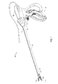
- Fig. 1 is a perspective view of an endoscopic bipolar forceps in accordance with an embodiment of the present disclosure
- Fig. 2 is a perspective view of an open bipolar forceps in accordance with an embodiment of the present disclosure
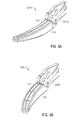
- Figs. 3A and 3B are perspective views of opposing jaw members according to an embodiment of the present disclosure
- Figs. 4A and 4B are exploded views of the opposing jaw members of Figs. 3A and 3B respectively;
- Fig. 5A is a perspective view of a sealing plate according to an embodiment of the present disclosure.
- Fig. 5B is a rear, cross-sectional view of the sealing plate of Fig. 5A .
- proximal refers to the end of the apparatus which is closer to the user and the term “distal” refers to the end of the apparatus which is farther away from the user.
- distal refers to the end of the apparatus which is farther away from the user.
- clinical refers to any medical professional (i.e., doctor, surgeon, nurse, or the like) performing a medical procedure involving the use of embodiments described herein.
- an instrument generally identified as forceps 10 may be used during various surgical procedures and includes a housing 20, a handle assembly 30, a rotating assembly 80, a trigger assembly 70, and an end effector assembly 100 that mutually cooperate to grasp, seal, and divide tubular vessels and vascular tissues.
- Forceps 10 includes a shaft 12 that has a distal end 14 dimensioned to mechanically engage the end effector assembly 100 and a proximal end 16 that mechanically engages the housing 20.
- the end effector assembly 100 includes opposing jaw members 110 and 120, which cooperate to effectively grasp tissue for sealing purposes.
- the jaw members 110 and 120 may be curved to facilitate manipulation of tissue and to provide better "line of sight" for accessing targeted tissues.
- Forceps 200 includes a pair of opposing shafts 212a and 212b having an end effector assembly 230 attached to the distal ends 216a and 216b thereof, respectively.
- End effector assembly 230 is similar in design to end effector assembly 100 and includes pair of opposing jaw members 232 and 234 that are pivotably connected about a pivot pin 265 and that are movable relative to one another to grasp tissue.
- Each shaft 212a and 212b includes a handle 215 and 217, respectively, disposed at the proximal end 214a and 214b thereof.
- Each handle 215 and 217 defines a finger hole 215 and 217a, respectively, therethrough for receiving a finger of the user.
- Finger holes 215a and 217a facilitate movement of the shafts 212a and 212b relative to one another which, in turn, pivot the jaw members 232 and 234 from an open position wherein the jaw members 232 and 234 are disposed in spaced relation relative to one another to a clamping or closed position wherein the jaw members 232 and 234 cooperate to grasp tissue therebetween.
- Figs. 3A and 3B are perspective views of opposing jaw members 310 and 320. Similar to jaw members 110 and 120, each of the jaw members 310 and 320 include: sealing plates 312 and 322, respectively; electrical jaw leads 325a and 325b, respectively; and support bases 316 and 326 formed as plastic overmolds. Electrical jaw leads 325a and 325b supply energy to one or both of the opposing jaw members 310 and 320.
- the opposing jaw members 310 and 320 include support bases 316 and 326 that extend distally from flanges 313 and 323, respectively.
- the support bases 316 and 326 are dimensioned to support insulative plates 319' and 329', which in turn, support electrically conductive sealing plates 312 and 322 thereon.
- Sealing plates 312 and 322 may be affixed atop the insulative plates 319' and 329', respectively, and support bases 319 and 329, respectively, in any known manner in the art, snap-fit, over-molding, stamping, ultrasonically welded, etc.
- the support bases 319 and 329, insulative plates 319' and 329', and sealing plates 312 and 322 are encapsulated by the outer insulative housings 316 and 326 by way of a subsequent overmolding process.
- the jaw members 310 and 320 are connected via an ultrasonic weld to electrical jaw leads 325a and 325b, respectively.
- the jaw members 310 and 320 also include proximal flanges 313 and 323 extending proximally from the support bases 319 and 329, respectively, each of which includes an elongated angled cam slot 317 and 327, respectively, defined therethrough.
- Jaw member 320 includes a series of stop members 390 disposed on the inner facing surface of electrically conductive sealing plate 312 to define a gap between opposing jaw members 310 and 320 during sealing and cutting of tissue. The series of stop members 390 are applied onto the sealing plate 312 during manufacturing.
- the electrically conductive sealing plates 312 and 322 and the insulator plates 319' and 329' include respective longitudinally-oriented knife slots 315a, 315a' and 315b, 315b', respectively, defined therethrough for reciprocation of the knife blade (not shown).
- sealing plate 500 is similar to sealing plate 322 described above. As shown, sealing plate 500 has a stainless steel layer 510 and ceramic layer 520. Like stop members 390, the ceramic layer 520 provides insulation between opposing jaw members 310, 320 (see Figs. 3A and 3B ) during sealing and cutting of tissue. Most ceramics are stable at elevated temperatures and usually exhibit low thermal and electrical conductivities, In addition, ceramic materials have high melting points and are resistant to oxidation, corrosion, or other forms of degradation to which metals are usually more prone.
- stainless steel layer 510 includes one or more depressions 512 which may be formed by stamping, a process where metal is formed by being pressed with an embossed pattern, bending, a manufacturing process that produces a V-shape, U-shape, or channel shape along a straight axis in ductile materials, or machining, a material-working processes in which power-driven machine tools, such as lathes, milling machines, and drill presses, are used with a sharp cutting tool to mechanically cut the material to achieve the desired geometry.
- each depression 512 may be any suitable shape including a shape having circular or non-circular cross-sectional areas. As shown, each depression 512 may be substantially hemispherically shaped.
- Stainless steel layer 510 may have a polymer coating to prevent corrosion. The polymer coating may be applied by vapor deposition, heat treatment or any other method that may be used to apply a coating to stainless steel layer 510.
- PVD physical vapor deposition
- CVD chemical vapor deposition
- PVD physical vapor deposition
- the substrate is exposed to one or more volatile precursors, which react and/or decompose on the substrate surface to produce the desired deposit.
- volatile by-products are also produced, which are removed by gas flow through a reaction chamber.
- PVD is a variety of vacuum deposition and is a general term used to describe any of a variety of methods to deposit thin films by the condensation of a vaporized form of the material onto various surfaces. This coating method involves purely physical processes such as high temperature vacuum evaporation or plasma sputter bombardment.
- Ceramic layer 520 may be positioned onto the reverse side or top of depressions 512 of the stainless steel layer 510 by vapor deposition, e.g., CVD or PVD.
- the tissue engaging surface or sealing plate 322 of jaw member 320 includes a series of projections that form a structured bore for the ceramic layer 520.
- the ceramic layer 520 may be vapor deposited onto the stainless steel layer 510 in a high volume vacuum chamber in order to manufacture sealing plate 500 at a high production rate and reduced expense due to the efficiency associated with vapor deposition.
- Ceramic layer 520 may have a thickness ranging from 10 angstroms to about 500 angstroms.
- Sealing plate 500 which includes stainless steel layer 510 and ceramic layer 520, may have a thickness ranging from 0.005 inches to 0.008 inches.
- jaw member 320 (or any of the aforementioned jaw members 120, 220) includes a series of stop members 390 that project from one or both jaw members and maintain a gap of about 0.001 inch to about 0.006 inches therebetween.
Landscapes
- Health & Medical Sciences (AREA)
- Surgery (AREA)
- Engineering & Computer Science (AREA)
- Life Sciences & Earth Sciences (AREA)
- Biomedical Technology (AREA)
- Otolaryngology (AREA)
- Nuclear Medicine, Radiotherapy & Molecular Imaging (AREA)
- Plasma & Fusion (AREA)
- Physics & Mathematics (AREA)
- Heart & Thoracic Surgery (AREA)
- Medical Informatics (AREA)
- Molecular Biology (AREA)
- Animal Behavior & Ethology (AREA)
- General Health & Medical Sciences (AREA)
- Public Health (AREA)
- Veterinary Medicine (AREA)
- Surgical Instruments (AREA)
Abstract
Description
- The present disclosure relates to an apparatus for performing an endoscopic electrosurgical procedure. More particularly, the present disclosure relates to an apparatus for performing an endoscopic electrosurgical procedure that employs an endoscopic electrosurgical apparatus that includes an end effector assembly configured for use with variously-sized access ports.
- Electrosurgical apparatuses (e.g., electrosurgical forceps) are well known in the medical arts and typically include a handle, a shaft and an end effector assembly operatively coupled to a distal end of the shaft that is configured to manipulate tissue (e.g., grasp and seal tissue). Electrosurgical forceps utilize both mechanical clamping action and electrical energy to effect homeostasis by heating the tissue and blood vessels to coagulate, cauterize, fuse, seal, cut, desiccate, and/or fulgurate tissue.
- As an alternative to open electrosurgical forceps for use with open surgical procedures, many modern surgeons use endoscopes and endoscopic electrosurgical apparatus (e.g., endoscopic forceps) for remotely accessing organs through smaller, puncture-like incisions. As a direct result thereof, patients tend to benefit from less scarring, less pain, and reduced healing time. Typically, the endoscopic forceps are inserted into the patient through one or more various types of cannulas or access ports (typically having an opening that ranges from about five millimeters to about fifteen millimeters) that has been made with a trocar; as can be appreciated, smaller cannulas are usually preferred.
- Endoscopic forceps that are configured for use with small cannulas (e.g., cannulas less than five millimeters) may present design challenges for a manufacturer of endoscopic instruments.
- An end effector assembly includes a pair of opposing jaw members. One or more of the jaw members includes a support base, optionally an electrical jaw lead, a sealing plate, and a ceramic or other electrically insulative layer. The sealing plate may be coupled to the optional electrical jaw lead and is mounted to the support base. The sealing plate includes a tissue engaging surface, an opposing surface, and a series of depressions formed within the opposing surface and projecting from the tissue engaging surface. One or more of the series of depressions may have a cross-sectional area that is one or more of circular in shape, hemispherical in shape, and rectangular in shape when the tissue engaging surface is viewed from above. In embodiments, two or more of the depressions of the series of depressions have different cross-sections. The series of depressions is formed by one or more of stamping, bending, and machining.
- The ceramic or other electrically insulative layer is deposited atop each of the series of depressions. The ceramic layer may be vapor deposited onto the series of depressions. The ceramic layer may have a thickness between about 10 angstroms and about 500 angstroms. The combination of the depressions that project from the tissue engaging surface and the ceramic layer form a corresponding series of nonconductive stop members for controlling the separation distance between opposing jaw members when closed about tissue. Preferably, the ceramic layer for each of the series of depression is surrounded by electrically conductive material of the sealing plate when the tissue engaging surface is viewed from above.
- In one aspect, a method of manufacturing a sealing plate of an end effector assembly includes providing one or more jaw members having a support base, an electrical jaw lead, and a sealing plate coupled to the electrical jaw lead and mounted to the support base. The sealing plate includes a tissue engaging surface and an opposing surface. The method includes forming a series of depressions within the opposing surface of the sealing plate such that the series of depressions project from the tissue engaging surface. On step includes depositing a ceramic layer atop each of the series of depressions to form a corresponding series of nonconductive stop members for controlling the separation distance between opposing jaw members when closed about tissue. In one manner, the depositing step involves vapor deposition in a high volume vacuum chamber. The forming step may involve one or more of stamping, bending, and machining.
- The above and other aspects, features, and advantages of the present disclosure will become more apparent in light of the following detailed description when taken in conjunction with the accompanying drawings in which:
-
Fig. 1 is a perspective view of an endoscopic bipolar forceps in accordance with an embodiment of the present disclosure; -
Fig. 2 is a perspective view of an open bipolar forceps in accordance with an embodiment of the present disclosure; -
Figs. 3A and 3B are perspective views of opposing jaw members according to an embodiment of the present disclosure; -
Figs. 4A and4B are exploded views of the opposing jaw members ofFigs. 3A and 3B respectively; -
Fig. 5A is a perspective view of a sealing plate according to an embodiment of the present disclosure; and -
Fig. 5B is a rear, cross-sectional view of the sealing plate ofFig. 5A . - Particular embodiments of the present disclosure are described hereinbelow with reference to the accompanying drawings; however, it is to be understood that the disclosed embodiments are merely exemplary of the disclosure and may be embodied in various forms. Well-known functions or constructions are not described in detail to avoid obscuring the present disclosure in unnecessary detail. Therefore, specific structural and functional details disclosed herein are not to be interpreted as limiting, but merely as a basis for the claims and as a representative basis for teaching one skilled in the art to variously employ the present disclosure in virtually any appropriately detailed structure.
- Like reference numerals may refer to similar or identical elements throughout the description of the figures. As shown in the drawings and described throughout the following description, as is traditional when referring to relative positioning on a surgical instrument, the term "proximal" refers to the end of the apparatus which is closer to the user and the term "distal" refers to the end of the apparatus which is farther away from the user. The term "clinician" refers to any medical professional (i.e., doctor, surgeon, nurse, or the like) performing a medical procedure involving the use of embodiments described herein.
- Turning now to
Fig. 1 , an instrument generally identified asforceps 10 may be used during various surgical procedures and includes ahousing 20, ahandle assembly 30, arotating assembly 80, atrigger assembly 70, and anend effector assembly 100 that mutually cooperate to grasp, seal, and divide tubular vessels and vascular tissues.Forceps 10 includes ashaft 12 that has adistal end 14 dimensioned to mechanically engage theend effector assembly 100 and aproximal end 16 that mechanically engages thehousing 20. Theend effector assembly 100 includes opposingjaw members jaw members - Examples of forceps are shown and described in commonly-owned
U.S. Application Serial No. 10/369,894 entitled "VESSEL SEALER AND DIVIDER AND METHOD MANUFACTURING SAME" and commonly ownedU.S. Application Serial No. 10/460,926 (now patent7,156,846 ) entitled "VESSEL SEALER AND DIVIDER FOR USE WITH SMALL TROCARS AND CANNULAS. - With regard to
Fig. 2 , anopen forceps 200 for use with various surgical procedures is shown.Forceps 200 includes a pair ofopposing shafts end effector assembly 230 attached to thedistal ends End effector assembly 230 is similar in design toend effector assembly 100 and includes pair ofopposing jaw members pivot pin 265 and that are movable relative to one another to grasp tissue. Eachshaft handle 215 and 217, respectively, disposed at theproximal end handle 215 and 217 defines afinger hole Finger holes shafts jaw members jaw members jaw members -
Figs. 3A and 3B are perspective views of opposingjaw members jaw members jaw members sealing plates support bases jaw members - Turning to
Figs. 4A and4B , the opposingjaw members support bases flanges conductive sealing plates Sealing plates support bases plates insulative housings jaw members - The
jaw members proximal flanges angled cam slot Jaw member 320 includes a series ofstop members 390 disposed on the inner facing surface of electricallyconductive sealing plate 312 to define a gap between opposingjaw members stop members 390 are applied onto the sealingplate 312 during manufacturing. The electricallyconductive sealing plates knife slots - With reference to
Fig. 5A , a perspective view of sealingplate 500 is shown.Sealing plate 500 is similar to sealingplate 322 described above. As shown, sealingplate 500 has astainless steel layer 510 andceramic layer 520. Likestop members 390, theceramic layer 520 provides insulation between opposingjaw members 310, 320 (seeFigs. 3A and 3B ) during sealing and cutting of tissue. Most ceramics are stable at elevated temperatures and usually exhibit low thermal and electrical conductivities, In addition, ceramic materials have high melting points and are resistant to oxidation, corrosion, or other forms of degradation to which metals are usually more prone. - As best shown in
Fig. 5B ,stainless steel layer 510 includes one ormore depressions 512 which may be formed by stamping, a process where metal is formed by being pressed with an embossed pattern, bending, a manufacturing process that produces a V-shape, U-shape, or channel shape along a straight axis in ductile materials, or machining, a material-working processes in which power-driven machine tools, such as lathes, milling machines, and drill presses, are used with a sharp cutting tool to mechanically cut the material to achieve the desired geometry. Accordingly, eachdepression 512 may be any suitable shape including a shape having circular or non-circular cross-sectional areas. As shown, eachdepression 512 may be substantially hemispherically shaped.Stainless steel layer 510 may have a polymer coating to prevent corrosion. The polymer coating may be applied by vapor deposition, heat treatment or any other method that may be used to apply a coating tostainless steel layer 510. - Two types of vapor deposition include chemical vapor deposition ("CVD") and physical vapor deposition ("PVD"). In a typical CVD process, the substrate is exposed to one or more volatile precursors, which react and/or decompose on the substrate surface to produce the desired deposit. Frequently, volatile by-products are also produced, which are removed by gas flow through a reaction chamber. PVD is a variety of vacuum deposition and is a general term used to describe any of a variety of methods to deposit thin films by the condensation of a vaporized form of the material onto various surfaces. This coating method involves purely physical processes such as high temperature vacuum evaporation or plasma sputter bombardment.
-
Ceramic layer 520 may be positioned onto the reverse side or top ofdepressions 512 of thestainless steel layer 510 by vapor deposition, e.g., CVD or PVD. In this instance, the tissue engaging surface or sealingplate 322 ofjaw member 320 includes a series of projections that form a structured bore for theceramic layer 520. Once the projections are formed, theceramic layer 520 may be vapor deposited onto thestainless steel layer 510 in a high volume vacuum chamber in order to manufacture sealingplate 500 at a high production rate and reduced expense due to the efficiency associated with vapor deposition.Ceramic layer 520 may have a thickness ranging from 10 angstroms to about 500 angstroms.Sealing plate 500, which includesstainless steel layer 510 andceramic layer 520, may have a thickness ranging from 0.005 inches to 0.008 inches. The resulting effect is that jaw member 320 (or any of theaforementioned jaw members 120, 220) includes a series ofstop members 390 that project from one or both jaw members and maintain a gap of about 0.001 inch to about 0.006 inches therebetween. - It should be understood that the foregoing description is only illustrative of the present disclosure. Various alternatives and modifications can be devised by those skilled in the art without departing from the disclosure. Accordingly, the present disclosure is intended to embrace all such alternatives, modifications and variances. The embodiments described with reference to the attached drawings are presented only to demonstrate certain examples of the disclosure. Other elements, steps, methods and techniques that are insubstantially different from those described above and/or in the appended claims are also intended to be within the scope of the disclosure.
Claims (9)
- An end effector assembly including a pair of opposing jaw members, at least one of the jaw members comprising:a support base;an electrical jaw lead;a sealing plate coupled to the electrical jaw lead and mounted to the support base, the sealing plate including:a tissue engaging surface and an opposing surface; anda series of depressions formed within the opposing surface and projecting from the tissue engaging surface; anda ceramic layer deposited atop each of the series of depressions, wherein the combination of the depressions projecting from the tissue engaging surface and their respective ceramic layers form a corresponding series of nonconductive stop members for controlling the separation distance between the pair of opposing jaw members.
- The end effector assembly according to claim 1, wherein the at least one of the series of depressions has a cross-sectional area that is at least one of circular in shape, hemispherical in shape, and rectangular in shape.
- The end effector assembly according to claim 1 or 2, wherein at least two of the depressions of the series of depressions have different cross-sections.
- The end effector assembly of claim 1, 2 or 3, wherein the ceramic layer is vapor deposited onto the series of depressions.
- The end effector assembly of claim 1, 2, 3 or 4, wherein the series of depressions is formed by at least one of stamping, bending, and machining.
- The end effector assembly according to claim 1, 2, 3, 4 or 5, wherein the ceramic layer has a thickness between about 10 angstroms and about 500 angstroms.
- A method of manufacturing a sealing plate of an end effector assembly, comprising the steps of:providing at least one jaw member having a support base, an electrical jaw lead, and a sealing plate coupled to the electrical jaw lead and mounted to the support base, the sealing plate including a tissue engaging surface and an opposing surface;forming a series of depressions within the opposing surface of the sealing plate such that the series of depressions project from the tissue engaging surface; anddepositing a ceramic layer atop each of the series of depressions to form a corresponding series of nonconductive stop members for controlling the separation distance between the at least one jaw member and an opposing jaw member.
- The method according to claim 7 wherein the depositing step comprises vapor deposition in a high volume vacuum chamber.
- The method according to claim 7 or 8 wherein the forming step comprises at least one of stamping, bending, and machining.
Applications Claiming Priority (1)
| Application Number | Priority Date | Filing Date | Title |
|---|---|---|---|
| US12/770,387 US20110270245A1 (en) | 2010-04-29 | 2010-04-29 | Sealing Plate Having Depressions with Ceramic Insulation |
Publications (2)
| Publication Number | Publication Date |
|---|---|
| EP2382936A1 true EP2382936A1 (en) | 2011-11-02 |
| EP2382936B1 EP2382936B1 (en) | 2015-06-17 |
Family
ID=44260830
Family Applications (1)
| Application Number | Title | Priority Date | Filing Date |
|---|---|---|---|
| EP11164273.2A Not-in-force EP2382936B1 (en) | 2010-04-29 | 2011-04-29 | Sealing plate having depressions with ceramic insulation |
Country Status (5)
| Country | Link |
|---|---|
| US (1) | US20110270245A1 (en) |
| EP (1) | EP2382936B1 (en) |
| JP (1) | JP2011229923A (en) |
| AU (1) | AU2011201957B2 (en) |
| CA (1) | CA2738240A1 (en) |
Cited By (2)
| Publication number | Priority date | Publication date | Assignee | Title |
|---|---|---|---|---|
| WO2017189402A1 (en) * | 2016-04-29 | 2017-11-02 | Ethicon Llc | Electrosurgical instrument with electrically conductive gap setting and tissue engaging members |
| US10251696B2 (en) | 2001-04-06 | 2019-04-09 | Covidien Ag | Vessel sealer and divider with stop members |
Families Citing this family (67)
| Publication number | Priority date | Publication date | Assignee | Title |
|---|---|---|---|---|
| US7364577B2 (en) | 2002-02-11 | 2008-04-29 | Sherwood Services Ag | Vessel sealing system |
| US9848938B2 (en) | 2003-11-13 | 2017-12-26 | Covidien Ag | Compressible jaw configuration with bipolar RF output electrodes for soft tissue fusion |
| US7367976B2 (en) | 2003-11-17 | 2008-05-06 | Sherwood Services Ag | Bipolar forceps having monopolar extension |
| US7628791B2 (en) | 2005-08-19 | 2009-12-08 | Covidien Ag | Single action tissue sealer |
| CA2561034C (en) | 2005-09-30 | 2014-12-09 | Sherwood Services Ag | Flexible endoscopic catheter with an end effector for coagulating and transfecting tissue |
| US8475453B2 (en) | 2006-10-06 | 2013-07-02 | Covidien Lp | Endoscopic vessel sealer and divider having a flexible articulating shaft |
| US8142473B2 (en) | 2008-10-03 | 2012-03-27 | Tyco Healthcare Group Lp | Method of transferring rotational motion in an articulating surgical instrument |
| US8187273B2 (en) | 2009-05-07 | 2012-05-29 | Tyco Healthcare Group Lp | Apparatus, system, and method for performing an electrosurgical procedure |
| US8246618B2 (en) | 2009-07-08 | 2012-08-21 | Tyco Healthcare Group Lp | Electrosurgical jaws with offset knife |
| US8133254B2 (en) | 2009-09-18 | 2012-03-13 | Tyco Healthcare Group Lp | In vivo attachable and detachable end effector assembly and laparoscopic surgical instrument and methods therefor |
| US8112871B2 (en) | 2009-09-28 | 2012-02-14 | Tyco Healthcare Group Lp | Method for manufacturing electrosurgical seal plates |
| US8439913B2 (en) | 2010-04-29 | 2013-05-14 | Covidien Lp | Pressure sensing sealing plate |
| US10265118B2 (en) | 2010-05-04 | 2019-04-23 | Covidien Lp | Pinion blade drive mechanism for a laparoscopic vessel dissector |
| GB2480498A (en) | 2010-05-21 | 2011-11-23 | Ethicon Endo Surgery Inc | Medical device comprising RF circuitry |
| US8672939B2 (en) | 2010-06-01 | 2014-03-18 | Covidien Lp | Surgical device for performing an electrosurgical procedure |
| US8647343B2 (en) | 2010-06-23 | 2014-02-11 | Covidien Lp | Surgical forceps for sealing and dividing tissue |
| US9028495B2 (en) | 2010-06-23 | 2015-05-12 | Covidien Lp | Surgical instrument with a separable coaxial joint |
| US8795269B2 (en) | 2010-07-26 | 2014-08-05 | Covidien Lp | Rotary tissue sealer and divider |
| US8814864B2 (en) | 2010-08-23 | 2014-08-26 | Covidien Lp | Method of manufacturing tissue sealing electrodes |
| US9005200B2 (en) | 2010-09-30 | 2015-04-14 | Covidien Lp | Vessel sealing instrument |
| US9017372B2 (en) | 2010-10-01 | 2015-04-28 | Covidien Lp | Blade deployment mechanisms for surgical forceps |
| US9655672B2 (en) | 2010-10-04 | 2017-05-23 | Covidien Lp | Vessel sealing instrument |
| US9113940B2 (en) | 2011-01-14 | 2015-08-25 | Covidien Lp | Trigger lockout and kickback mechanism for surgical instruments |
| US8900232B2 (en) | 2011-05-06 | 2014-12-02 | Covidien Lp | Bifurcated shaft for surgical instrument |
| US8939972B2 (en) | 2011-05-06 | 2015-01-27 | Covidien Lp | Surgical forceps |
| US8685009B2 (en) | 2011-05-16 | 2014-04-01 | Covidien Lp | Thread-like knife for tissue cutting |
| US8852185B2 (en) | 2011-05-19 | 2014-10-07 | Covidien Lp | Apparatus for performing an electrosurgical procedure |
| US9615877B2 (en) | 2011-06-17 | 2017-04-11 | Covidien Lp | Tissue sealing forceps |
| US8745840B2 (en) | 2011-07-11 | 2014-06-10 | Covidien Lp | Surgical forceps and method of manufacturing thereof |
| US9039732B2 (en) | 2011-07-11 | 2015-05-26 | Covidien Lp | Surgical forceps |
| US8845636B2 (en) | 2011-09-16 | 2014-09-30 | Covidien Lp | Seal plate with insulation displacement connection |
| US20130123776A1 (en) | 2011-10-24 | 2013-05-16 | Ethicon Endo-Surgery, Inc. | Battery shut-off algorithm in a battery powered device |
| USD680220S1 (en) | 2012-01-12 | 2013-04-16 | Coviden IP | Slider handle for laparoscopic device |
| US8939975B2 (en) | 2012-07-17 | 2015-01-27 | Covidien Lp | Gap control via overmold teeth and hard stops |
| US9192421B2 (en) | 2012-07-24 | 2015-11-24 | Covidien Lp | Blade lockout mechanism for surgical forceps |
| WO2015017995A1 (en) | 2013-08-07 | 2015-02-12 | Covidien Lp | Bipolar surgical instrument with tissue stop |
| KR102134566B1 (en) | 2013-08-07 | 2020-07-17 | 코비디엔 엘피 | Bipolar surgical instrument |
| US20160038220A1 (en) | 2014-08-11 | 2016-02-11 | Covidien Lp | Surgical instruments and methods for performing tonsillectomy and adenoidectomy procedures |
| US10080606B2 (en) | 2014-09-17 | 2018-09-25 | Covidien Lp | Method of forming a member of an end effector |
| US10159524B2 (en) | 2014-12-22 | 2018-12-25 | Ethicon Llc | High power battery powered RF amplifier topology |
| US10987159B2 (en) | 2015-08-26 | 2021-04-27 | Covidien Lp | Electrosurgical end effector assemblies and electrosurgical forceps configured to reduce thermal spread |
| US10959771B2 (en) | 2015-10-16 | 2021-03-30 | Ethicon Llc | Suction and irrigation sealing grasper |
| US10959806B2 (en) | 2015-12-30 | 2021-03-30 | Ethicon Llc | Energized medical device with reusable handle |
| US10426543B2 (en) | 2016-01-23 | 2019-10-01 | Covidien Lp | Knife trigger for vessel sealer |
| US10765471B2 (en) | 2016-04-15 | 2020-09-08 | Bolder Surgical, Llc | Electrosurgical sealer and divider |
| US10987156B2 (en) | 2016-04-29 | 2021-04-27 | Ethicon Llc | Electrosurgical instrument with electrically conductive gap setting member and electrically insulative tissue engaging members |
| US10682154B2 (en) | 2016-08-02 | 2020-06-16 | Covidien Lp | Cutting mechanisms for surgical end effector assemblies, instruments, and systems |
| US10631887B2 (en) | 2016-08-15 | 2020-04-28 | Covidien Lp | Electrosurgical forceps for video assisted thoracoscopic surgery and other surgical procedures |
| US10751117B2 (en) | 2016-09-23 | 2020-08-25 | Ethicon Llc | Electrosurgical instrument with fluid diverter |
| US11033325B2 (en) | 2017-02-16 | 2021-06-15 | Cilag Gmbh International | Electrosurgical instrument with telescoping suction port and debris cleaner |
| US11497546B2 (en) | 2017-03-31 | 2022-11-15 | Cilag Gmbh International | Area ratios of patterned coatings on RF electrodes to reduce sticking |
| US11172980B2 (en) | 2017-05-12 | 2021-11-16 | Covidien Lp | Electrosurgical forceps for grasping, treating, and/or dividing tissue |
| US10973567B2 (en) | 2017-05-12 | 2021-04-13 | Covidien Lp | Electrosurgical forceps for grasping, treating, and/or dividing tissue |
| USD854149S1 (en) | 2017-06-08 | 2019-07-16 | Covidien Lp | End effector for open vessel sealer |
| USD843574S1 (en) | 2017-06-08 | 2019-03-19 | Covidien Lp | Knife for open vessel sealer |
| USD854684S1 (en) | 2017-06-08 | 2019-07-23 | Covidien Lp | Open vessel sealer with mechanical cutter |
| US11490951B2 (en) | 2017-09-29 | 2022-11-08 | Cilag Gmbh International | Saline contact with electrodes |
| US11033323B2 (en) | 2017-09-29 | 2021-06-15 | Cilag Gmbh International | Systems and methods for managing fluid and suction in electrosurgical systems |
| US11484358B2 (en) | 2017-09-29 | 2022-11-01 | Cilag Gmbh International | Flexible electrosurgical instrument |
| US11376062B2 (en) | 2018-10-12 | 2022-07-05 | Covidien Lp | Electrosurgical forceps |
| US11471211B2 (en) | 2018-10-12 | 2022-10-18 | Covidien Lp | Electrosurgical forceps |
| US11350982B2 (en) | 2018-12-05 | 2022-06-07 | Covidien Lp | Electrosurgical forceps |
| US11523861B2 (en) | 2019-03-22 | 2022-12-13 | Covidien Lp | Methods for manufacturing a jaw assembly for an electrosurgical forceps |
| US11877790B2 (en) | 2020-01-07 | 2024-01-23 | Covidien Lp | Surgical forceps having jaw members |
| US11622804B2 (en) | 2020-03-16 | 2023-04-11 | Covidien Lp | Forceps with linear trigger mechanism |
| US11660109B2 (en) | 2020-09-08 | 2023-05-30 | Covidien Lp | Cutting elements for surgical instruments such as for use in robotic surgical systems |
| US11957342B2 (en) | 2021-11-01 | 2024-04-16 | Cilag Gmbh International | Devices, systems, and methods for detecting tissue and foreign objects during a surgical operation |
Citations (9)
| Publication number | Priority date | Publication date | Assignee | Title |
|---|---|---|---|---|
| EP1681027A1 (en) * | 2005-01-14 | 2006-07-19 | Sherwood Services AG | Vessel sealer and divider with rotating sealer and cutter |
| US7150097B2 (en) * | 2003-06-13 | 2006-12-19 | Sherwood Services Ag | Method of manufacturing jaw assembly for vessel sealer and divider |
| US7156846B2 (en) | 2003-06-13 | 2007-01-02 | Sherwood Services Ag | Vessel sealer and divider for use with small trocars and cannulas |
| EP1769767A1 (en) * | 2005-09-30 | 2007-04-04 | Sherwood Services AG | In-line vessel sealer and divider |
| EP1810625A1 (en) * | 2006-01-24 | 2007-07-25 | Sherwood Services AG | Vessel sealer and divider for large tissue structures |
| EP1886637A1 (en) * | 2006-08-08 | 2008-02-13 | Covidien AG | System and method for controlling RF output during tissue sealing |
| EP1920725A2 (en) * | 2006-11-08 | 2008-05-14 | Covidien AG | In-line vessel sealer and divider |
| EP1946715A1 (en) * | 2005-03-31 | 2008-07-23 | Covidien AG | Electrosurgical forceps with slow closure sealing plates and method of sealing tissue |
| EP2105104A2 (en) * | 2008-03-27 | 2009-09-30 | Tyco Healthcare Group, LP | Endoscopic vessel sealer and divider for large tissue structures |
Family Cites Families (4)
| Publication number | Priority date | Publication date | Assignee | Title |
|---|---|---|---|---|
| JP4499992B2 (en) * | 2001-04-06 | 2010-07-14 | コヴィディエン アクチェンゲゼルシャフト | Vascular sealing machine and splitting machine having non-conductive stop member |
| SE521973C2 (en) * | 2001-12-27 | 2003-12-23 | Cerbio Tech Ab | Surface coating process, biocompatible coating and biocompatible coating device |
| US20050049632A1 (en) * | 2002-01-22 | 2005-03-03 | Yukio Inokuti | Ceramic-coated instruments for medical use, ceramic-coated instruments for studying living organisms and process for producing the same |
| AU2006225179B2 (en) * | 2005-09-30 | 2012-07-26 | Covidien Ag | In-line vessel sealer and divider |
-
2010
- 2010-04-29 US US12/770,387 patent/US20110270245A1/en not_active Abandoned
-
2011
- 2011-04-28 CA CA2738240A patent/CA2738240A1/en not_active Abandoned
- 2011-04-28 JP JP2011102433A patent/JP2011229923A/en active Pending
- 2011-04-29 EP EP11164273.2A patent/EP2382936B1/en not_active Not-in-force
- 2011-04-29 AU AU2011201957A patent/AU2011201957B2/en not_active Ceased
Patent Citations (9)
| Publication number | Priority date | Publication date | Assignee | Title |
|---|---|---|---|---|
| US7150097B2 (en) * | 2003-06-13 | 2006-12-19 | Sherwood Services Ag | Method of manufacturing jaw assembly for vessel sealer and divider |
| US7156846B2 (en) | 2003-06-13 | 2007-01-02 | Sherwood Services Ag | Vessel sealer and divider for use with small trocars and cannulas |
| EP1681027A1 (en) * | 2005-01-14 | 2006-07-19 | Sherwood Services AG | Vessel sealer and divider with rotating sealer and cutter |
| EP1946715A1 (en) * | 2005-03-31 | 2008-07-23 | Covidien AG | Electrosurgical forceps with slow closure sealing plates and method of sealing tissue |
| EP1769767A1 (en) * | 2005-09-30 | 2007-04-04 | Sherwood Services AG | In-line vessel sealer and divider |
| EP1810625A1 (en) * | 2006-01-24 | 2007-07-25 | Sherwood Services AG | Vessel sealer and divider for large tissue structures |
| EP1886637A1 (en) * | 2006-08-08 | 2008-02-13 | Covidien AG | System and method for controlling RF output during tissue sealing |
| EP1920725A2 (en) * | 2006-11-08 | 2008-05-14 | Covidien AG | In-line vessel sealer and divider |
| EP2105104A2 (en) * | 2008-03-27 | 2009-09-30 | Tyco Healthcare Group, LP | Endoscopic vessel sealer and divider for large tissue structures |
Cited By (4)
| Publication number | Priority date | Publication date | Assignee | Title |
|---|---|---|---|---|
| US10251696B2 (en) | 2001-04-06 | 2019-04-09 | Covidien Ag | Vessel sealer and divider with stop members |
| US10265121B2 (en) | 2001-04-06 | 2019-04-23 | Covidien Ag | Vessel sealer and divider |
| US10687887B2 (en) | 2001-04-06 | 2020-06-23 | Covidien Ag | Vessel sealer and divider |
| WO2017189402A1 (en) * | 2016-04-29 | 2017-11-02 | Ethicon Llc | Electrosurgical instrument with electrically conductive gap setting and tissue engaging members |
Also Published As
| Publication number | Publication date |
|---|---|
| AU2011201957A1 (en) | 2011-11-17 |
| CA2738240A1 (en) | 2011-10-29 |
| EP2382936B1 (en) | 2015-06-17 |
| AU2011201957B2 (en) | 2014-03-27 |
| JP2011229923A (en) | 2011-11-17 |
| US20110270245A1 (en) | 2011-11-03 |
Similar Documents
| Publication | Publication Date | Title |
|---|---|---|
| EP2382936B1 (en) | Sealing plate having depressions with ceramic insulation | |
| US10265121B2 (en) | Vessel sealer and divider | |
| US8632539B2 (en) | Vessel sealer and divider | |
| US9707031B2 (en) | Surgical forceps and method of manufacturing thereof | |
| EP3165189B1 (en) | Non-stick coated electrosurgical instruments and method for manufacturing the same | |
| EP1681027B1 (en) | Vessel sealer and divider with rotating sealer and cutter | |
| EP2105105B1 (en) | In-line vessel sealer and divider | |
| EP1769767B1 (en) | In-line vessel sealer and divider | |
| US7131971B2 (en) | Vessel sealer and divider | |
| EP1645237B1 (en) | Endoscopic bipolar electrosurgical forceps | |
| EP2039314B1 (en) | Open vessel sealing instrument with hourglass cutting mechanism and over-ratchet safety | |
| EP1594755B1 (en) | Vessel sealer and divider | |
| EP2377480A1 (en) | Sealing plate temperature control | |
| EP1633265A1 (en) | Vessel sealer and divider for use with small trocars and cannulas | |
| CA2532713C (en) | Vessel sealer and divider with rotating sealer and cutter | |
| AU2013231195A1 (en) | In-line vessel sealer and divider |
Legal Events
| Date | Code | Title | Description |
|---|---|---|---|
| AK | Designated contracting states |
Kind code of ref document: A1 Designated state(s): AL AT BE BG CH CY CZ DE DK EE ES FI FR GB GR HR HU IE IS IT LI LT LU LV MC MK MT NL NO PL PT RO RS SE SI SK SM TR |
|
| AX | Request for extension of the european patent |
Extension state: BA ME |
|
| PUAI | Public reference made under article 153(3) epc to a published international application that has entered the european phase |
Free format text: ORIGINAL CODE: 0009012 |
|
| 17P | Request for examination filed |
Effective date: 20120327 |
|
| RAP1 | Party data changed (applicant data changed or rights of an application transferred) |
Owner name: COVIDIEN LP |
|
| GRAP | Despatch of communication of intention to grant a patent |
Free format text: ORIGINAL CODE: EPIDOSNIGR1 |
|
| INTG | Intention to grant announced |
Effective date: 20150119 |
|
| GRAS | Grant fee paid |
Free format text: ORIGINAL CODE: EPIDOSNIGR3 |
|
| GRAA | (expected) grant |
Free format text: ORIGINAL CODE: 0009210 |
|
| AK | Designated contracting states |
Kind code of ref document: B1 Designated state(s): AL AT BE BG CH CY CZ DE DK EE ES FI FR GB GR HR HU IE IS IT LI LT LU LV MC MK MT NL NO PL PT RO RS SE SI SK SM TR |
|
| REG | Reference to a national code |
Ref country code: GB Ref legal event code: FG4D |
|
| REG | Reference to a national code |
Ref country code: CH Ref legal event code: EP |
|
| REG | Reference to a national code |
Ref country code: AT Ref legal event code: REF Ref document number: 731454 Country of ref document: AT Kind code of ref document: T Effective date: 20150715 |
|
| REG | Reference to a national code |
Ref country code: IE Ref legal event code: FG4D |
|
| REG | Reference to a national code |
Ref country code: DE Ref legal event code: R096 Ref document number: 602011017142 Country of ref document: DE |
|
| PG25 | Lapsed in a contracting state [announced via postgrant information from national office to epo] |
Ref country code: LT Free format text: LAPSE BECAUSE OF FAILURE TO SUBMIT A TRANSLATION OF THE DESCRIPTION OR TO PAY THE FEE WITHIN THE PRESCRIBED TIME-LIMIT Effective date: 20150617 Ref country code: HR Free format text: LAPSE BECAUSE OF FAILURE TO SUBMIT A TRANSLATION OF THE DESCRIPTION OR TO PAY THE FEE WITHIN THE PRESCRIBED TIME-LIMIT Effective date: 20150617 Ref country code: FI Free format text: LAPSE BECAUSE OF FAILURE TO SUBMIT A TRANSLATION OF THE DESCRIPTION OR TO PAY THE FEE WITHIN THE PRESCRIBED TIME-LIMIT Effective date: 20150617 Ref country code: NO Free format text: LAPSE BECAUSE OF FAILURE TO SUBMIT A TRANSLATION OF THE DESCRIPTION OR TO PAY THE FEE WITHIN THE PRESCRIBED TIME-LIMIT Effective date: 20150917 |
|
| REG | Reference to a national code |
Ref country code: AT Ref legal event code: MK05 Ref document number: 731454 Country of ref document: AT Kind code of ref document: T Effective date: 20150617 |
|
| REG | Reference to a national code |
Ref country code: LT Ref legal event code: MG4D Ref country code: NL Ref legal event code: MP Effective date: 20150617 |
|
| PG25 | Lapsed in a contracting state [announced via postgrant information from national office to epo] |
Ref country code: LV Free format text: LAPSE BECAUSE OF FAILURE TO SUBMIT A TRANSLATION OF THE DESCRIPTION OR TO PAY THE FEE WITHIN THE PRESCRIBED TIME-LIMIT Effective date: 20150617 Ref country code: BG Free format text: LAPSE BECAUSE OF FAILURE TO SUBMIT A TRANSLATION OF THE DESCRIPTION OR TO PAY THE FEE WITHIN THE PRESCRIBED TIME-LIMIT Effective date: 20150917 Ref country code: RS Free format text: LAPSE BECAUSE OF FAILURE TO SUBMIT A TRANSLATION OF THE DESCRIPTION OR TO PAY THE FEE WITHIN THE PRESCRIBED TIME-LIMIT Effective date: 20150617 Ref country code: GR Free format text: LAPSE BECAUSE OF FAILURE TO SUBMIT A TRANSLATION OF THE DESCRIPTION OR TO PAY THE FEE WITHIN THE PRESCRIBED TIME-LIMIT Effective date: 20150918 |
|
| PG25 | Lapsed in a contracting state [announced via postgrant information from national office to epo] |
Ref country code: EE Free format text: LAPSE BECAUSE OF FAILURE TO SUBMIT A TRANSLATION OF THE DESCRIPTION OR TO PAY THE FEE WITHIN THE PRESCRIBED TIME-LIMIT Effective date: 20150617 |
|
| PG25 | Lapsed in a contracting state [announced via postgrant information from national office to epo] |
Ref country code: ES Free format text: LAPSE BECAUSE OF FAILURE TO SUBMIT A TRANSLATION OF THE DESCRIPTION OR TO PAY THE FEE WITHIN THE PRESCRIBED TIME-LIMIT Effective date: 20150617 Ref country code: RO Free format text: LAPSE BECAUSE OF NON-PAYMENT OF DUE FEES Effective date: 20150617 Ref country code: SK Free format text: LAPSE BECAUSE OF FAILURE TO SUBMIT A TRANSLATION OF THE DESCRIPTION OR TO PAY THE FEE WITHIN THE PRESCRIBED TIME-LIMIT Effective date: 20150617 Ref country code: IS Free format text: LAPSE BECAUSE OF FAILURE TO SUBMIT A TRANSLATION OF THE DESCRIPTION OR TO PAY THE FEE WITHIN THE PRESCRIBED TIME-LIMIT Effective date: 20151017 Ref country code: PT Free format text: LAPSE BECAUSE OF FAILURE TO SUBMIT A TRANSLATION OF THE DESCRIPTION OR TO PAY THE FEE WITHIN THE PRESCRIBED TIME-LIMIT Effective date: 20151019 Ref country code: AT Free format text: LAPSE BECAUSE OF FAILURE TO SUBMIT A TRANSLATION OF THE DESCRIPTION OR TO PAY THE FEE WITHIN THE PRESCRIBED TIME-LIMIT Effective date: 20150617 Ref country code: CZ Free format text: LAPSE BECAUSE OF FAILURE TO SUBMIT A TRANSLATION OF THE DESCRIPTION OR TO PAY THE FEE WITHIN THE PRESCRIBED TIME-LIMIT Effective date: 20150617 Ref country code: PL Free format text: LAPSE BECAUSE OF FAILURE TO SUBMIT A TRANSLATION OF THE DESCRIPTION OR TO PAY THE FEE WITHIN THE PRESCRIBED TIME-LIMIT Effective date: 20150617 |
|
| REG | Reference to a national code |
Ref country code: DE Ref legal event code: R097 Ref document number: 602011017142 Country of ref document: DE |
|
| REG | Reference to a national code |
Ref country code: FR Ref legal event code: PLFP Year of fee payment: 6 |
|
| PLBE | No opposition filed within time limit |
Free format text: ORIGINAL CODE: 0009261 |
|
| STAA | Information on the status of an ep patent application or granted ep patent |
Free format text: STATUS: NO OPPOSITION FILED WITHIN TIME LIMIT |
|
| PG25 | Lapsed in a contracting state [announced via postgrant information from national office to epo] |
Ref country code: IT Free format text: LAPSE BECAUSE OF FAILURE TO SUBMIT A TRANSLATION OF THE DESCRIPTION OR TO PAY THE FEE WITHIN THE PRESCRIBED TIME-LIMIT Effective date: 20150617 Ref country code: DK Free format text: LAPSE BECAUSE OF FAILURE TO SUBMIT A TRANSLATION OF THE DESCRIPTION OR TO PAY THE FEE WITHIN THE PRESCRIBED TIME-LIMIT Effective date: 20150617 |
|
| 26N | No opposition filed |
Effective date: 20160318 |
|
| PG25 | Lapsed in a contracting state [announced via postgrant information from national office to epo] |
Ref country code: SI Free format text: LAPSE BECAUSE OF FAILURE TO SUBMIT A TRANSLATION OF THE DESCRIPTION OR TO PAY THE FEE WITHIN THE PRESCRIBED TIME-LIMIT Effective date: 20150617 Ref country code: BE Free format text: LAPSE BECAUSE OF NON-PAYMENT OF DUE FEES Effective date: 20160430 |
|
| REG | Reference to a national code |
Ref country code: CH Ref legal event code: PL |
|
| PG25 | Lapsed in a contracting state [announced via postgrant information from national office to epo] |
Ref country code: BE Free format text: LAPSE BECAUSE OF FAILURE TO SUBMIT A TRANSLATION OF THE DESCRIPTION OR TO PAY THE FEE WITHIN THE PRESCRIBED TIME-LIMIT Effective date: 20150617 Ref country code: LU Free format text: LAPSE BECAUSE OF FAILURE TO SUBMIT A TRANSLATION OF THE DESCRIPTION OR TO PAY THE FEE WITHIN THE PRESCRIBED TIME-LIMIT Effective date: 20160429 |
|
| PG25 | Lapsed in a contracting state [announced via postgrant information from national office to epo] |
Ref country code: LI Free format text: LAPSE BECAUSE OF NON-PAYMENT OF DUE FEES Effective date: 20160430 Ref country code: CH Free format text: LAPSE BECAUSE OF NON-PAYMENT OF DUE FEES Effective date: 20160430 |
|
| REG | Reference to a national code |
Ref country code: FR Ref legal event code: PLFP Year of fee payment: 7 |
|
| PG25 | Lapsed in a contracting state [announced via postgrant information from national office to epo] |
Ref country code: SE Free format text: LAPSE BECAUSE OF FAILURE TO SUBMIT A TRANSLATION OF THE DESCRIPTION OR TO PAY THE FEE WITHIN THE PRESCRIBED TIME-LIMIT Effective date: 20150617 Ref country code: NL Free format text: LAPSE BECAUSE OF FAILURE TO SUBMIT A TRANSLATION OF THE DESCRIPTION OR TO PAY THE FEE WITHIN THE PRESCRIBED TIME-LIMIT Effective date: 20150617 |
|
| REG | Reference to a national code |
Ref country code: FR Ref legal event code: PLFP Year of fee payment: 8 |
|
| PG25 | Lapsed in a contracting state [announced via postgrant information from national office to epo] |
Ref country code: CY Free format text: LAPSE BECAUSE OF FAILURE TO SUBMIT A TRANSLATION OF THE DESCRIPTION OR TO PAY THE FEE WITHIN THE PRESCRIBED TIME-LIMIT Effective date: 20150617 Ref country code: HU Free format text: LAPSE BECAUSE OF FAILURE TO SUBMIT A TRANSLATION OF THE DESCRIPTION OR TO PAY THE FEE WITHIN THE PRESCRIBED TIME-LIMIT; INVALID AB INITIO Effective date: 20110429 Ref country code: SM Free format text: LAPSE BECAUSE OF FAILURE TO SUBMIT A TRANSLATION OF THE DESCRIPTION OR TO PAY THE FEE WITHIN THE PRESCRIBED TIME-LIMIT Effective date: 20150617 |
|
| PG25 | Lapsed in a contracting state [announced via postgrant information from national office to epo] |
Ref country code: TR Free format text: LAPSE BECAUSE OF FAILURE TO SUBMIT A TRANSLATION OF THE DESCRIPTION OR TO PAY THE FEE WITHIN THE PRESCRIBED TIME-LIMIT Effective date: 20150617 Ref country code: MK Free format text: LAPSE BECAUSE OF FAILURE TO SUBMIT A TRANSLATION OF THE DESCRIPTION OR TO PAY THE FEE WITHIN THE PRESCRIBED TIME-LIMIT Effective date: 20150617 Ref country code: MT Free format text: LAPSE BECAUSE OF NON-PAYMENT OF DUE FEES Effective date: 20160430 Ref country code: MC Free format text: LAPSE BECAUSE OF FAILURE TO SUBMIT A TRANSLATION OF THE DESCRIPTION OR TO PAY THE FEE WITHIN THE PRESCRIBED TIME-LIMIT Effective date: 20150617 |
|
| PG25 | Lapsed in a contracting state [announced via postgrant information from national office to epo] |
Ref country code: AL Free format text: LAPSE BECAUSE OF FAILURE TO SUBMIT A TRANSLATION OF THE DESCRIPTION OR TO PAY THE FEE WITHIN THE PRESCRIBED TIME-LIMIT Effective date: 20150617 |
|
| PGFP | Annual fee paid to national office [announced via postgrant information from national office to epo] |
Ref country code: IE Payment date: 20200318 Year of fee payment: 10 Ref country code: GB Payment date: 20200323 Year of fee payment: 10 |
|
| PGFP | Annual fee paid to national office [announced via postgrant information from national office to epo] |
Ref country code: FR Payment date: 20200319 Year of fee payment: 10 |
|
| PGFP | Annual fee paid to national office [announced via postgrant information from national office to epo] |
Ref country code: DE Payment date: 20200319 Year of fee payment: 10 |
|
| REG | Reference to a national code |
Ref country code: DE Ref legal event code: R119 Ref document number: 602011017142 Country of ref document: DE |
|
| GBPC | Gb: european patent ceased through non-payment of renewal fee |
Effective date: 20210429 |
|
| PG25 | Lapsed in a contracting state [announced via postgrant information from national office to epo] |
Ref country code: DE Free format text: LAPSE BECAUSE OF NON-PAYMENT OF DUE FEES Effective date: 20211103 Ref country code: FR Free format text: LAPSE BECAUSE OF NON-PAYMENT OF DUE FEES Effective date: 20210430 Ref country code: GB Free format text: LAPSE BECAUSE OF NON-PAYMENT OF DUE FEES Effective date: 20210429 |
|
| PG25 | Lapsed in a contracting state [announced via postgrant information from national office to epo] |
Ref country code: IE Free format text: LAPSE BECAUSE OF NON-PAYMENT OF DUE FEES Effective date: 20210429 |