EP2386252A1 - Continuous-filament thread having a plurality of barbs and a barbed suture - Google Patents
Continuous-filament thread having a plurality of barbs and a barbed suture Download PDFInfo
- Publication number
- EP2386252A1 EP2386252A1 EP10162574A EP10162574A EP2386252A1 EP 2386252 A1 EP2386252 A1 EP 2386252A1 EP 10162574 A EP10162574 A EP 10162574A EP 10162574 A EP10162574 A EP 10162574A EP 2386252 A1 EP2386252 A1 EP 2386252A1
- Authority
- EP
- European Patent Office
- Prior art keywords
- suture
- barbs
- continuous
- disposition
- filament thread
- Prior art date
- Legal status (The legal status is an assumption and is not a legal conclusion. Google has not performed a legal analysis and makes no representation as to the accuracy of the status listed.)
- Granted
Links
- 230000002457 bidirectional effect Effects 0.000 claims description 33
- 238000005304 joining Methods 0.000 claims description 5
- 239000000126 substance Substances 0.000 claims description 5
- 238000004519 manufacturing process Methods 0.000 abstract description 7
- 238000005520 cutting process Methods 0.000 description 30
- 239000000463 material Substances 0.000 description 22
- -1 polytrimethylene carbonate Polymers 0.000 description 22
- 210000001519 tissue Anatomy 0.000 description 18
- 206010052428 Wound Diseases 0.000 description 13
- 208000027418 Wounds and injury Diseases 0.000 description 13
- 230000008901 benefit Effects 0.000 description 13
- 238000000034 method Methods 0.000 description 9
- 239000003795 chemical substances by application Substances 0.000 description 8
- 229920001577 copolymer Polymers 0.000 description 8
- 239000000835 fiber Substances 0.000 description 8
- 239000000203 mixture Substances 0.000 description 8
- 241000290260 Stemodia Species 0.000 description 6
- 210000004027 cell Anatomy 0.000 description 6
- 239000003102 growth factor Substances 0.000 description 6
- 229920000642 polymer Polymers 0.000 description 6
- 230000008569 process Effects 0.000 description 5
- 108050007372 Fibroblast Growth Factor Proteins 0.000 description 4
- 102000018233 Fibroblast Growth Factor Human genes 0.000 description 4
- 102000003745 Hepatocyte Growth Factor Human genes 0.000 description 4
- 108090000100 Hepatocyte Growth Factor Proteins 0.000 description 4
- 108010025020 Nerve Growth Factor Proteins 0.000 description 4
- 102000015336 Nerve Growth Factor Human genes 0.000 description 4
- 108010038512 Platelet-Derived Growth Factor Proteins 0.000 description 4
- 102000010780 Platelet-Derived Growth Factor Human genes 0.000 description 4
- 108010009583 Transforming Growth Factors Proteins 0.000 description 4
- 102000009618 Transforming Growth Factors Human genes 0.000 description 4
- 108010073929 Vascular Endothelial Growth Factor A Proteins 0.000 description 4
- 102000005789 Vascular Endothelial Growth Factors Human genes 0.000 description 4
- 108010019530 Vascular Endothelial Growth Factors Proteins 0.000 description 4
- 239000000654 additive Substances 0.000 description 4
- 238000004873 anchoring Methods 0.000 description 4
- 238000002316 cosmetic surgery Methods 0.000 description 4
- 238000001125 extrusion Methods 0.000 description 4
- 229940126864 fibroblast growth factor Drugs 0.000 description 4
- 229940053128 nerve growth factor Drugs 0.000 description 4
- 239000008177 pharmaceutical agent Substances 0.000 description 4
- 229920001343 polytetrafluoroethylene Polymers 0.000 description 4
- 230000002411 adverse Effects 0.000 description 3
- 229920002463 poly(p-dioxanone) polymer Polymers 0.000 description 3
- 239000000622 polydioxanone Substances 0.000 description 3
- 239000007787 solid Substances 0.000 description 3
- KIUKXJAPPMFGSW-DNGZLQJQSA-N (2S,3S,4S,5R,6R)-6-[(2S,3R,4R,5S,6R)-3-Acetamido-2-[(2S,3S,4R,5R,6R)-6-[(2R,3R,4R,5S,6R)-3-acetamido-2,5-dihydroxy-6-(hydroxymethyl)oxan-4-yl]oxy-2-carboxy-4,5-dihydroxyoxan-3-yl]oxy-5-hydroxy-6-(hydroxymethyl)oxan-4-yl]oxy-3,4,5-trihydroxyoxane-2-carboxylic acid Chemical compound CC(=O)N[C@H]1[C@H](O)O[C@H](CO)[C@@H](O)[C@@H]1O[C@H]1[C@H](O)[C@@H](O)[C@H](O[C@H]2[C@@H]([C@@H](O[C@H]3[C@@H]([C@@H](O)[C@H](O)[C@H](O3)C(O)=O)O)[C@H](O)[C@@H](CO)O2)NC(C)=O)[C@@H](C(O)=O)O1 KIUKXJAPPMFGSW-DNGZLQJQSA-N 0.000 description 2
- 102000008186 Collagen Human genes 0.000 description 2
- 108010035532 Collagen Proteins 0.000 description 2
- AEMRFAOFKBGASW-UHFFFAOYSA-N Glycolic acid Polymers OCC(O)=O AEMRFAOFKBGASW-UHFFFAOYSA-N 0.000 description 2
- 102000014015 Growth Differentiation Factors Human genes 0.000 description 2
- 108010050777 Growth Differentiation Factors Proteins 0.000 description 2
- 108010002352 Interleukin-1 Proteins 0.000 description 2
- 241001465754 Metazoa Species 0.000 description 2
- 239000004952 Polyamide Substances 0.000 description 2
- 239000004698 Polyethylene Substances 0.000 description 2
- 229920000954 Polyglycolide Polymers 0.000 description 2
- 239000004743 Polypropylene Substances 0.000 description 2
- 239000013543 active substance Substances 0.000 description 2
- 239000000853 adhesive Substances 0.000 description 2
- 230000001070 adhesive effect Effects 0.000 description 2
- 239000000730 antalgic agent Substances 0.000 description 2
- 239000002260 anti-inflammatory agent Substances 0.000 description 2
- 229940121363 anti-inflammatory agent Drugs 0.000 description 2
- 239000004599 antimicrobial Substances 0.000 description 2
- 230000009286 beneficial effect Effects 0.000 description 2
- 230000003115 biocidal effect Effects 0.000 description 2
- 239000003124 biologic agent Substances 0.000 description 2
- 230000015572 biosynthetic process Effects 0.000 description 2
- 210000000988 bone and bone Anatomy 0.000 description 2
- 230000001413 cellular effect Effects 0.000 description 2
- 210000001612 chondrocyte Anatomy 0.000 description 2
- 229920001436 collagen Polymers 0.000 description 2
- 210000002808 connective tissue Anatomy 0.000 description 2
- 239000000645 desinfectant Substances 0.000 description 2
- 230000002708 enhancing effect Effects 0.000 description 2
- 239000004744 fabric Substances 0.000 description 2
- 210000002950 fibroblast Anatomy 0.000 description 2
- 238000009499 grossing Methods 0.000 description 2
- 229920002674 hyaluronan Polymers 0.000 description 2
- 229960003160 hyaluronic acid Drugs 0.000 description 2
- 230000003993 interaction Effects 0.000 description 2
- 239000000178 monomer Substances 0.000 description 2
- 239000005014 poly(hydroxyalkanoate) Substances 0.000 description 2
- 229920000747 poly(lactic acid) Polymers 0.000 description 2
- 229920000070 poly-3-hydroxybutyrate Polymers 0.000 description 2
- 229920002791 poly-4-hydroxybutyrate Polymers 0.000 description 2
- 229920002647 polyamide Polymers 0.000 description 2
- 229920001707 polybutylene terephthalate Polymers 0.000 description 2
- 229920001610 polycaprolactone Polymers 0.000 description 2
- 229920000728 polyester Polymers 0.000 description 2
- 229920000573 polyethylene Polymers 0.000 description 2
- 229920000139 polyethylene terephthalate Polymers 0.000 description 2
- 239000005020 polyethylene terephthalate Substances 0.000 description 2
- 229920000903 polyhydroxyalkanoate Polymers 0.000 description 2
- 229920001155 polypropylene Polymers 0.000 description 2
- 239000004810 polytetrafluoroethylene Substances 0.000 description 2
- 229920000166 polytrimethylene carbonate Polymers 0.000 description 2
- 229920002635 polyurethane Polymers 0.000 description 2
- 239000004814 polyurethane Substances 0.000 description 2
- 229920002981 polyvinylidene fluoride Polymers 0.000 description 2
- 239000002243 precursor Substances 0.000 description 2
- 230000009467 reduction Effects 0.000 description 2
- 210000001082 somatic cell Anatomy 0.000 description 2
- 210000000130 stem cell Anatomy 0.000 description 2
- 230000000638 stimulation Effects 0.000 description 2
- VBEQCZHXXJYVRD-GACYYNSASA-N uroanthelone Chemical compound C([C@@H](C(=O)N[C@H](C(=O)N[C@@H](CS)C(=O)N[C@@H](CC(N)=O)C(=O)N[C@@H](CS)C(=O)N[C@H](C(=O)N[C@@H]([C@@H](C)CC)C(=O)NCC(=O)N[C@@H](CC=1C=CC(O)=CC=1)C(=O)N[C@@H](CO)C(=O)NCC(=O)N[C@@H](CC(O)=O)C(=O)N[C@@H](CCCNC(N)=N)C(=O)N[C@@H](CS)C(=O)N[C@@H](CCC(N)=O)C(=O)N[C@@H]([C@@H](C)O)C(=O)N[C@@H](CCCNC(N)=N)C(=O)N[C@@H](CC(O)=O)C(=O)N[C@@H](CC(C)C)C(=O)N[C@@H](CCCNC(N)=N)C(=O)N[C@@H](CC=1C2=CC=CC=C2NC=1)C(=O)N[C@@H](CC=1C2=CC=CC=C2NC=1)C(=O)N[C@@H](CCC(O)=O)C(=O)N[C@@H](CC(C)C)C(=O)N[C@@H](CCCNC(N)=N)C(O)=O)C(C)C)[C@@H](C)O)NC(=O)[C@H](CO)NC(=O)[C@H](CC(O)=O)NC(=O)[C@H](CC(C)C)NC(=O)[C@H](CO)NC(=O)[C@H](CCC(O)=O)NC(=O)[C@@H](NC(=O)[C@H](CC=1NC=NC=1)NC(=O)[C@H](CCSC)NC(=O)[C@H](CS)NC(=O)[C@@H](NC(=O)CNC(=O)CNC(=O)[C@H](CC(N)=O)NC(=O)[C@H](CC(C)C)NC(=O)[C@H](CS)NC(=O)[C@H](CC=1C=CC(O)=CC=1)NC(=O)CNC(=O)[C@H](CC(O)=O)NC(=O)[C@H](CC=1C=CC(O)=CC=1)NC(=O)[C@H](CO)NC(=O)[C@H](CO)NC(=O)[C@H]1N(CCC1)C(=O)[C@H](CS)NC(=O)CNC(=O)[C@H]1N(CCC1)C(=O)[C@H](CC=1C=CC(O)=CC=1)NC(=O)[C@H](CO)NC(=O)[C@@H](N)CC(N)=O)C(C)C)[C@@H](C)CC)C1=CC=C(O)C=C1 VBEQCZHXXJYVRD-GACYYNSASA-N 0.000 description 2
- 230000029663 wound healing Effects 0.000 description 2
- 230000037303 wrinkles Effects 0.000 description 2
- 208000005422 Foreign-Body reaction Diseases 0.000 description 1
- 206010019909 Hernia Diseases 0.000 description 1
- 206010021519 Impaired healing Diseases 0.000 description 1
- 208000012287 Prolapse Diseases 0.000 description 1
- 206010046543 Urinary incontinence Diseases 0.000 description 1
- 229920005603 alternating copolymer Polymers 0.000 description 1
- XAGFODPZIPBFFR-UHFFFAOYSA-N aluminium Chemical compound [Al] XAGFODPZIPBFFR-UHFFFAOYSA-N 0.000 description 1
- 229910052782 aluminium Inorganic materials 0.000 description 1
- 239000004411 aluminium Substances 0.000 description 1
- 239000012298 atmosphere Substances 0.000 description 1
- 229920001400 block copolymer Polymers 0.000 description 1
- 239000008280 blood Substances 0.000 description 1
- 210000004369 blood Anatomy 0.000 description 1
- 210000004204 blood vessel Anatomy 0.000 description 1
- 210000000845 cartilage Anatomy 0.000 description 1
- 239000002537 cosmetic Substances 0.000 description 1
- 230000023753 dehiscence Effects 0.000 description 1
- 230000001419 dependent effect Effects 0.000 description 1
- 239000003814 drug Substances 0.000 description 1
- 229940079593 drug Drugs 0.000 description 1
- 238000012377 drug delivery Methods 0.000 description 1
- 210000005069 ears Anatomy 0.000 description 1
- 230000000694 effects Effects 0.000 description 1
- 238000002674 endoscopic surgery Methods 0.000 description 1
- 230000003628 erosive effect Effects 0.000 description 1
- 210000004709 eyebrow Anatomy 0.000 description 1
- 210000000887 face Anatomy 0.000 description 1
- 210000003195 fascia Anatomy 0.000 description 1
- 239000002223 garnet Substances 0.000 description 1
- 230000009477 glass transition Effects 0.000 description 1
- 229920000578 graft copolymer Polymers 0.000 description 1
- 238000001746 injection moulding Methods 0.000 description 1
- 208000014674 injury Diseases 0.000 description 1
- 238000002357 laparoscopic surgery Methods 0.000 description 1
- 238000003698 laser cutting Methods 0.000 description 1
- 210000003041 ligament Anatomy 0.000 description 1
- 238000003754 machining Methods 0.000 description 1
- 238000002406 microsurgery Methods 0.000 description 1
- 210000003205 muscle Anatomy 0.000 description 1
- 230000001338 necrotic effect Effects 0.000 description 1
- 210000005036 nerve Anatomy 0.000 description 1
- 210000000056 organ Anatomy 0.000 description 1
- 238000010791 quenching Methods 0.000 description 1
- 230000005855 radiation Effects 0.000 description 1
- 229920005604 random copolymer Polymers 0.000 description 1
- 210000004872 soft tissue Anatomy 0.000 description 1
- 238000011477 surgical intervention Methods 0.000 description 1
- 210000002435 tendon Anatomy 0.000 description 1
- 229920001897 terpolymer Polymers 0.000 description 1
- 229920006029 tetra-polymer Polymers 0.000 description 1
- 239000004753 textile Substances 0.000 description 1
- 230000008733 trauma Effects 0.000 description 1
- 230000037314 wound repair Effects 0.000 description 1
- 239000002759 woven fabric Substances 0.000 description 1
- 229910052727 yttrium Inorganic materials 0.000 description 1
- VWQVUPCCIRVNHF-UHFFFAOYSA-N yttrium atom Chemical compound [Y] VWQVUPCCIRVNHF-UHFFFAOYSA-N 0.000 description 1
Images

Classifications
-
- A—HUMAN NECESSITIES
- A61—MEDICAL OR VETERINARY SCIENCE; HYGIENE
- A61B—DIAGNOSIS; SURGERY; IDENTIFICATION
- A61B17/00—Surgical instruments, devices or methods, e.g. tourniquets
- A61B17/04—Surgical instruments, devices or methods, e.g. tourniquets for suturing wounds; Holders or packages for needles or suture materials
- A61B17/06—Needles ; Sutures; Needle-suture combinations; Holders or packages for needles or suture materials
- A61B17/06166—Sutures
- A61B2017/06176—Sutures with protrusions, e.g. barbs
-
- A—HUMAN NECESSITIES
- A61—MEDICAL OR VETERINARY SCIENCE; HYGIENE
- A61B—DIAGNOSIS; SURGERY; IDENTIFICATION
- A61B17/00—Surgical instruments, devices or methods, e.g. tourniquets
- A61B17/04—Surgical instruments, devices or methods, e.g. tourniquets for suturing wounds; Holders or packages for needles or suture materials
- A61B17/06—Needles ; Sutures; Needle-suture combinations; Holders or packages for needles or suture materials
- A61B17/06166—Sutures
- A61B2017/06185—Sutures hollow or tubular
Definitions
- the present invention relates to a continuous-filament thread having a plurality of barbs, a method for producing a continuous-filament thread having a plurality of barbs, a barbed suture and a method for producing a barbed suture.
- a barbed suture typically includes an elongated body that has spaced barbs which project from the body surface along the body length.
- the barbs are arranged on the elongate body in such a way that the suture can be pulled through the tissue along the direction of the barbs without any great resistance and without tissue trauma.
- the barbs stand upright and anchor themselves, and therefore also the suture, in the surrounding tissue area. This ensures that the suture cannot be pulled back through the incision channel.
- barbed sutures has been the provision of a non-slip attribute.
- Barbed sutures are described, for example, in the documents US 3,123,077 A , EP 1 559 266 B1 , EP 1 560 683 B1 and EP 1 556 946 B1 .
- the barbs are often arranged in a symmetrical fashion on the suture.
- the barbs may be formed in a helical pattern on the sutures, wherein the helix has a defined twist direction, cut depth and cut distance.
- a helical disposition of the barbs may lead to a coil of the suture depending on the length of the incision, which may have an adverse effect on the scaring.
- barbed sutures A further disadvantage that is associated with barbed sutures relates to their producing process. Normally, barbed sutures having distinct properties, in particular in view of barb geometry, have to be produced in an elaborate and time-consuming process.
- the object of the present invention is therefore to make available a barbed material including a barbed suture which avoids disadvantages known from the prior art.
- the barbed material according to the present invention should allow for a comfortable provision of barbed sutures having distinct properties depending on the wound to be closed by the barbed suture.
- the present invention provides a continuous-filament thread comprising a continuous-filament thread body comprising barbs, in particular a plurality of barbs.
- the barbs preferably project from the continuous-filament thread body.
- continuous-filament thread and “continuous-filament thread body”, respectively as used according to the invention, preferably relates to a thread and thread body, respectively that is unprocessed at least in view of its length ("endless-filament thread” and “endless-filament thread body”, respectively).
- barbs as used according to the invention encompasses at least one barb.
- plurality of barbs encompasses at least two or more barbs.
- thread and "thread body”, respectively as used according to the invention, may include a fibre, a yarn, a strand, a monofilament, in particular a pseudo-monofilament, or a multifilament, in particular a braided or intertwined multifilament.
- the continuous-filament thread body may comprise a uniform barb configuration or a different or varying, in particular an alternating or a random barb configuration.
- configuration according to the invention is to be understood in its broadest sense and in particular encompasses the design, shape, geometry and/or disposition of the barbs. More specifically, the barbs may have a uniform or different or varying, in particular alternating or random, configuration in view of barb length, barb height, cutting depth, cutting distance, cutting angle, cutting angle offset and, combinations thereof.
- the continuous-filament thread body comprises a varying, in particular alternating or random, barb configuration along its length.
- a multiplicity of barbed sutures having distinct barb configurations may be produced from a single continuous-filament thread according to the present invention.
- continuous-filament thread body comprises a random barb configuration.
- the barbs have a shape that is selected from the group consisting of escutcheon-shape, shield-shape, scale-shape, wedge-shape, thorn-shape, W-shape, arrow-shape, spike-shape, tin-shape, V-shape and, combinations thereof.
- the barbs are preferably pointed or tapered at their free ends.
- the barbs may have a multi-tip configuration, in particular a twin-tip configuration.
- An example for barbs having a twin-tip configuration is the above mentioned W-shaped formation of barbs.
- Barbs having a twin-tip configuration may in particular be based on flat cuts into the continuous-filament thread body, preferably formed with a small angular offset and in small intervals from each other.
- the barbs are arranged in a uniform disposition on the continuous-filament thread body.
- the barbs are arranged in different or varying, in particular alternating or, more preferable, random, dispositions on the continuous-filament thread body.
- the barbs may have a disposition on the continuous-filament thread body that is selected from the group consisting of a row disposition, a staggered disposition, an overlapping disposition, an offset disposition, an offset and partially overlapping disposition, a zigzag disposition, a random or arbitrary disposition, a meander-like disposition, a serpentine-like disposition, a sinus-like disposition, a spiral disposition, a helical disposition, and combinations thereof.
- the barbs are arranged in the form of left-handed and/or right-handed spirals and/or helices on the continuous-filament thread body. More specifically, left-handed and/or right-handed spirals and/or helices may be present on the continuous-filament thread body in a different or varying, in particular alternating or random, disposition.
- a spiral or helical barb disposition having a different or varying, in particular alternating or random, spiral or helical twist contributes to the reduction of suture coiling.
- adverse interactions between a tissue and a coiled suture may be significantly reduced, thereby enhancing wound healing.
- the barbs are arranged in a unidirectional disposition on the continuous-filament thread body.
- the term "unidirectional disposition” as used herein, relates to a barb disposition, wherein the barbs are orientated in the same direction on the continuous-filament thread body.
- the barbs are arranged in a multidirectional, in particular bidirectional, disposition on the continuous-filament thread body.
- multidirectional disposition relates to a disposition of barbs, in which the barbs are oriented or aligned in multiple directions on the continuous-filament thread body.
- bidirectional disposition relates to a disposition of barbs, in which the barbs are oriented or aligned in two different directions. Preferably, the barbs are orientated or aligned in opposing directions.
- the barbs for a first continuous-filament thread body section are preferably formed in the direction of a second continuous-filament thread body section and, for the second continuous-filament thread body section, are formed in the direction of the first continuous-filament thread body section.
- the continuous-filament thread body may comprise in a further embodiment repeating units of unidirectionally arranged barbs.
- the continuous-filament thread body may comprise repeating units of multidirectionally arranged barbs.
- the continuous-filament thread body comprises repeating units of bidirectionally arranged barbs.
- each unit may comprise a first section and a second section, wherein, seen in the longitudinal direction of the continuous-filament thread body, the barbs of the first section are orientated in the direction of the second section and the barbs of the second section are orientated in the direction of the first section.
- the continuous-filament thread body may comprise at least two, in particular two or three, multidirectional dispositions of barbs.
- the continuous-filament thread body may comprise at least two, in particular two, bidirectional dispositions of barbs on its surface. It is particularly preferable if, in relation to a first bidirectional disposition of barbs, a second bidirectional disposition of barbs is formed on the continuous-filament thread body at approximately 180° in the circumferential direction and preferably offset in relation to the first bidirectional disposition.
- the continuous-filament thread body comprises three bidirectional dispositions of barbs.
- a second bidirectional disposition of barbs is formed on the continuous-filament thread body at approximately 120° in the circumferential direction and preferably offset in relation to the first bidirectional disposition, which second bidirectional disposition of barbs is in turn formed at approximately 120° in the circumferential direction and preferably offset in relation to a third bidirectional disposition of barbs, such that the third bidirectional disposition of barbs is likewise formed at approximately 120° in the circumferential direction and preferably offset in relation to the first bidirectional disposition of barbs.
- the continuous-filament thread body may comprise more than three, in particular four, five or six, multidirectional, in particular bidirectional, dispositions of barbs on the continuous-filament thread body.
- the continuous-filament thread body comprises sections that are free of barbs, in the following also denoted as barbless sections.
- the barbless sections may generally serve as potentially cutting areas so as to obtain barbed sutures from the continuous-filament thread body of the present invention.
- the barbless sections at least are also present in a barbed suture that is obtained from the continuous-filament thread. More specifically, the barbless sections may serve as junction areas for joining lengths or sections, in particular sutures bodies, obtained by cutting the continuous-filament thread body.
- the barbless sections may serve as attachment areas for attaching medical instruments, in particular inserting instruments such as a surgical needle, and/or for attaching medical devices such as meshes to a barbed suture that may be obtained from the continuous filament thread. Furthermore, the barbless sections may advantageously facilitate the identification of the centre of a barbed suture that may be obtained from the continuous-filament thread.
- terminal ends of the continuous-filament thread body may be free of barbs.
- the continuous-filament thread body may comprise a different or varying, in particular an alternating or a random, disposition of barbed sections and barbless sections.
- the continuous-filament thread body comprises sections having barbs that are interspaced by sections having no barbs.
- the continuous-filament thread body may comprise an alternating disposition of sections having barbs (barbed sections) and sections having no barbs (barbless sections).
- the barbed sections may comprise unidirectionally or multidirectionally, in particular bidirectionally, arranged barbs.
- the continuous-filament thread body is designed as a mass or solid continuous-filament thread body.
- the continuous-filament thread body is free of a lumen or the like.
- the continuous-filament thread body may be designed in the form of a fibre, yarn, strand, monofilament, pseudo-monofilament or multifilament, in particular braided or intertwined multifilament.
- the continuous-filament thread body may be designed as a hollow continuous-filament thread body, in particular as a tubular continuous-filament thread body, preferably as continuous-tube or continuous-hose.
- the hollow continuous-filament thread body comprises a closed wall, wherein the continuous-filament thread body preferably comprises open ends.
- a hollow, in particular tubular, continuous-filament thread body may be produced, by way of example, by means of an extrusion process. The barbs may project into the interior and/or exterior of the hollow continuous-filament thread body.
- the barbs may be designed as cuts into the hollow continuous-filament thread body, wherein the barbs preferably do not break through the wall of the hollow continuous-filament thread body.
- the barbs may be designed as breakthroughs, i.e. the barbs are formed completely breaking through the wall of the hollow continuous-filament thread body.
- the continuous-filament thread body may not be limited in view of its cross section. In general, a circular cross section of the continuous-filament thread body is preferred. However, other cross-sectional shapes are likewise conceivable.
- the continuous-filament thread body can have an oval, triangular, rosette-like, square, trapezoidal, rhomboid, pentagonal, hexagonal, star-shaped or cross-shaped cross section.
- Such cross-sectional shapes can readily be formed by means of suitable extrusions dies, which can be produced specific to a customer with any desired cross-sectional shape.
- the thread body may comprise at least one, in particular one, set of barbs. It may also be within the scope of the present invention that the barbs are configured in at least two, in particular two, three, four, five or more, sets, each set having a barb configuration different from the barb configuration of the other set.
- the continuous-filament thread body is made from a material selected from the group consisting of a bio-absorbable material, a non-absorbable material, and combinations thereof.
- the continuous-filament thread body is made of a polymer.
- the term "polymer” as used according to the invention may include copolymers, in particular random copolymers, alternating copolymers, graft copolymers and/or block copolymers.
- copolymer relates to a polymer that is composed of at least two different monomer units. Accordingly, it may be within the scope of the present invention that the continuous-filament thread body is also made from terpolymers, tetrapolymers or the like.
- the continuous-filament thread body is made of a polyhydroxyalkanoate, a copolymer thereof or a mixture thereof. More specifically, the continuous-filament thread body is preferable made of a bio-absorbable material that is selected from the group consisting of polylactide, polyglycolide, polydioxanone, polytrimethylene carbonate, poly- ⁇ -caprolactone, poly-3-hydroxybutyrate, poly-4-hydroxybutyrate, copolymers thereof and mixtures thereof.
- the continuous-filament thread body is made of a non-absorbable material that is selected from the group consisting of polyamide, polyester such as polyethylene terephthalate, polypropylene terephthalate and/or polybutylene terephthalate, polyethylene, polypropylene, polyurethane, polytetrafluoroethylene, in particular expanded polytetrafluorethylene, polyvinylidene difluoride, polytetrafluoropropylene, polyhexafluoropropylene, polyetherester, copolymers thereof, and mixtures thereof.
- polyamide polyamide
- polyester such as polyethylene terephthalate, polypropylene terephthalate and/or polybutylene terephthalate
- polyethylene polypropylene
- polyurethane polytetrafluoroethylene
- polyvinylidene difluoride polytetrafluoropropylene
- polyhexafluoropropylene polyetherester
- copolymers thereof
- the continuous-filament thread body may comprise additives such as biological agents, medical agents, pharmaceutical agents, cells, and combinations thereof.
- Biological active agents may be selected from the group consisting of differentiation factors, growth factors, recruiting factors, adhesion factors, and combinations thereof.
- Appropriate growth factors may be selected from the group consisting of fibroblast growth factor (FGF), transforming growth factor (TGF), platelet derived growth factor (PDGF), epidermal growth factor (EGF), granulocyte-macrophage colony stimulation factor (GMCSF), vascular endothelial growth factor (VEGF), insuline-like growth factor (IGF), hepatocyte growth factor (HGF), interieucin-1 B (IL-1 B), interleucin-8 (IL-8), nerve growth factor (NGF), and combinations thereof.
- FGF fibroblast growth factor
- TGF transforming growth factor
- PDGF platelet derived growth factor
- EGF epidermal growth factor
- GMCSF granulocyte-macrophage colony stimulation factor
- Medical and pharmaceutical agents may be selected from the group consisting of antimicrobial agents, in particular antibiotic agents, disinfecting agents, growth-promoting agents, anti-inflammatory agents, analgetic agents, odor-controlling agents, and mixtures thereof.
- Preferred cellular additives may be somatic cells, in particular autologous cells, like fibroblasts, chondrocytes and/or precursors cells, in particular stem cells, for example.
- such substances like collagen and/or hyaluronic acid for example, may be particularly beneficial in the field of plastic surgery to achieve cosmetically satisfactory results, like a smoothing of wrinkles, for example.
- the continuous-filament thread body may be present in a drawn or undrawn state.
- the continuous-filament thread body may be present in a sterile form.
- Another aspect of the present invention refers to a method for producing a continuous-filament thread comprising a continuous-filament thread body comprising barbs, in particular a plurality of barbs, which preferably project from the continuous-filament thread body, wherein the barbs are cut into a barbless continuous-filament thread body, i.e. the barbs are cut into a continuous-filament thread body having no barbs.
- the barbs may be formed using any suitable method, including cutting, in particular mechanical cutting, injection molding, stamping, laser, and the like.
- the barbs may be cut into an undrawn or into a drawn continuous-filament thread body.
- the barbs are cut in while the continuous-filament thread body is rotated.
- the continuous-filament thread body is twisted prior to cutting in barbs and untwisted again after the barbs have been cut in.
- the embodiments described in this paragraph are advantageous in that a radial, in particular spiral-shaped or helical-shaped disposition of barbs may be generated on the continuous-filament thread body.
- a cutting in particular mechanical cutting, conventional cutting devices comprising a cutting bed, at least one cutting plate and holding or fixing elements such as vices, chucks, holding or clamping jaws, may be used.
- a cutting bed with a groove, wherein the groove is provided to receive the continuous-filament thread body that is to be cut.
- the at least one cutting plate it is possible, when using at least one cutting plate, to specifically influence the cutting depth with which the barbs are cut into the continuous-filament thread body. This is because the at least one cutting plate is generally designed such that, by means thereof, cuts can be made only in the areas of the continuous-filament thread body, which protrude from the groove. This advantageously contributes to a safe cutting.
- lasers that can be used, are in principle, gas lasers, for example CO 2 lasers, and also solid-state lasers, for example, Nd:YAG lasers (neodymium-doped yttrium aluminium garnet lasers).
- a suitable laser cutting machine generally comprises a laser beam source, a beam guide, and at least movable focusing lens (concave mirror or positive lens).
- the beam leaving the beam source is either guided by fibre-optic cables for example in a Nd:YAG laser, or by a deflecting mirror, for example in a CO 2 laser, to the machining lens which focuses the laser beam and in this way generates the power densities needed for the cutting, generally in the range of 10 6 to 10 9 W/cm 2 .
- Corresponding cutting laser methods are sufficiently known to a person skilled in the art, such that further details are not given here.
- a drawing of the continuous-filament thread body such a drawing may be performed in a temperature range of between 20° and 80° C above the glass transition temperature of the thread body material.
- infrared radiation can be used, to generate a suitable heat for the drawing process.
- the thread body is usually guided across a roller system, so-called drawing frame, in which the rollers can have different speeds of rotation. Generally, each subsequent roller has a higher speed of rotation than the proceeding roller of the drawing system.
- intermittent drawing the thread body may be clamped between the clamping jaws of a tensioning device and then drawn.
- a drawing ratio of between 2.5 and 8 and particularly of between 3 and 5 may be chosen.
- the thread body can be subjected to various post-treatment steps.
- the continuous-filament thread body is generally tempered (heat-treated) in a vacuum or reduced pressure atmosphere. In this way, crystallinity of the continuous-filament thread body may be increased and the residual monomer content reduced.
- a further advantage afforded by a post-treatment of the continuous-filament thread body material is the reduced susceptibility to shrinkage.
- Another aspect of the present invention relates to a barbed suture comprising at least one elongate suture body comprising barbs, in particular a plurality of barbs, which preferably project from the at least one suture body.
- the barbed suture is preferably obtainable or obtained from a continuous-filament thread according to the present invention.
- At least one suture body includes one, two, three, four, five, six, seven eight or more suture bodies.
- the barbed suture may, by way of example, be arranged as a linear barbed suture, as star-like barbed suture or as a branched, in particular dendrimer-like, barbed suture.
- the at least one suture body may comprise a uniform barb configuration or a different or varying, in particular an alternating or, more preferable, a random, barb configuration. More specifically, the barbs may have a uniform or different or varying, in particular alternating or random, configuration in view of barb design, barb geometry and/or barb shape, in particular in view of barb length, barb height, cutting depth, cutting distance, cutting angle, cutting angle offset and, combinations thereof.
- the barbs have a shape that is selected from the group consisting of escutcheon-shape, shield-shape, scale-shape, wedge-shape, thorn-shape, W-shape, arrow-shape, spike-shape, tin-shape, V-shape and, combinations thereof.
- the barbs are preferably pointed or tapered at their free ends.
- the barbs may have a multi-tip configuration, in particular a twin-tip configuration.
- An example for barbs having a twin-tip configuration is the above mentioned W-shaped formation of barbs.
- Barbs having a twin-tip configuration may in particular be based on flat cuts into the at least one suture body, preferably formed with a small angular offset and in small intervals from each other.
- the barbs are arranged in a uniform disposition on the at least one suture body.
- different or varying, in particular alternating or random, dispositions may also be within the scope of the present invention.
- the barbs may have a disposition on the at least one suture body that is selected from the group consisting of a row disposition, a staggered disposition, an overlapping disposition, an offset disposition, an offset and partially overlapping disposition, a zigzag disposition, a random or arbitrary disposition, a meander-like disposition, a serpentine-like disposition, a sinus-like disposition, a spiral disposition, a helical disposition, and combinations thereof.
- the barbs are arranged in the form of left-handed and/or right-handed spirals and/or helices on the at least one suture body. More specifically, left-handed and/or right-handed spirals and/or helices may be present on the at least one suture body in a different or varying, in particular alternating or random, disposition.
- a spiral or helical barb disposition having a different or varying, in particular alternating or random, spiral or helical twist, contributes to the reduction of suture coiling.
- adverse interactions between a tissue and a coiled suture may be significantly reduced, thereby enhancing wound healing.
- the barbs are arranged in a unidirectional disposition on the at least one suture body.
- the barbs are arranged in a multidirectional, in particular bidirectional, disposition on the at least one suture body.
- the barbs are orientated or aligned in opposing directions. More preferably, seen in the longitudinal direction of the at least one suture body, the barbs for a first suture body section are preferably formed in the direction of a second suture body section and, for the second suture body section, are formed in the direction of the first suture body section.
- the at least one suture body may comprise in a further embodiment repeating units of unidirectionally arranged barbs.
- the at least one suture body may comprise repeating units of multidirectionally arranged barbs.
- the at least one suture body comprises repeating units of bidirectionally arranged barbs.
- each unit may comprise a first section and a second section, wherein, seen in the longitudinal direction of the at least one suture body, the barbs of the first section are orientated in the direction of the second section and the barbs of the second section are orientated in the direction of the first section.
- the at least one suture body may comprise at least two, in particular two or three, multidirectional dispositions of barbs.
- the at least one suture body may comprise at least two, in particular two, bidirectional dispositions of barbs on its surface. It is particularly preferable if, in relation to a first bidirectional disposition of barbs, a second bidirectional disposition of barbs is formed on the at least one suture body at approximately 180° in the circumferential direction and preferably offset in relation to the first bidirectional disposition.
- the at least one suture body may comprise three bidirectional dispositions of barbs.
- a second bidirectional disposition of barbs is formed on the at least one suture body at approximately 120° in the circumferential direction and preferably offset in relation to the first bidirectional disposition, which second bidirectional disposition of barbs is in turn formed at approximately 120° in the circumferential direction and preferably offset in relation to a third bidirectional disposition of barbs, such that the third bidirectional disposition of barbs is likewise formed at approximately 120° in the circumferential direction and preferably offset in relation to the first bidirectional disposition of barbs.
- the barbs may be in principle arranged user-defined on the at least one suture body.
- the barbs may be arranged in the centre of the at least one suture body.
- the at least one suture body comprises sections that are free of barbs, in the following also denoted as barbless sections.
- the at least one suture body may comprise a barbless section around the centre of the at least one suture body.
- the barbless section may expediently serve as a control or reference section, which facilitates the identification of the barbed suture's centre.
- the barbless section may serve as a control or reference section in order to avoid an accidental sliding of the at least one suture body beyond its centre into a tissue to be treated.
- the at least one suture body may have at least one terminal section (terminal end), in particular one, two or, if appropriate, more than two terminal sections, that is free of barbs.
- These barbless sections may beneficially serve as attachment areas for attaching the at least one suture body to at least one further suture body.
- the barbless sections may serve as attachment areas for attaching medical instruments, in particular inserting instruments such as a surgical needle and/or for attaching medical devices such as meshes to the at least one suture body.
- the at least one suture body may comprise a different or varying disposition of barbed sections and barbless sections.
- the at least one suture body comprises sections having barbs that are interspaced by sections having no barbs. More specifically, the at least one suture body may comprise an alternating disposition of sections having barbs and sections having no barbs.
- the barbed sections may comprise unidirectionally or multidirectionally, preferably bidirectionally, arranged barbs.
- the at least one suture body may have a first barbless terminal section, which is followed by a barbed section, which followed by a barbless section, which is followed by a barbed section, which is followed by a second terminal section.
- the at least one suture body is designed as at least one mass or solid suture body. More specifically, the at least one suture body may be designed in the form of a fibre, yarn, strand, monofilament, pseudo-monofilament or multifilament, in particular braided or intertwined multifilament.
- the at least one suture body may be designed as at least one hollow suture body, in particular as at least one tubular suture body.
- the at least one hollow suture body comprises a closed wall.
- the at least one hollow suture body comprises open ends.
- Hollow suture bodies according to the invention may be produced, by way of example, by means of an extrusion process.
- the barbs may project into the interior and/or exterior of the at least one hollow suture body.
- the barbs protrude into the exterior of the at least one hollow suture body.
- the barbs may be designed as cuts into the at least one hollow suture body, wherein the barbs do not break through the wall of the at least one hollow suture body.
- the barbs may be designed as breakthroughs, i.e. the barbs are formed completely breaking through the wall of the at least one hollow suture body.
- Hollow suture bodies according to the present invention may be used as self-anchoring delivery tubes, drainage tubes, catheters, drug delivery systems or the like.
- the at least one suture body may not be limited in view of its cross section.
- a circular cross section of the at least one suture body is preferred.
- other cross-sectional shapes are likewise conceivable.
- the at least one suture body can have an oval, triangular, rosette-like, square, trapezoidal, rhomboid, pentagonal, hexagonal, star-shaped or cross-shaped cross section.
- Such cross-sectional shapes can readily be formed by means of suitable extrusions dies, which can be produced specific to a customer with any desired cross-sectional shape.
- the at least one suture body may comprise at least one, in particular one, set of barbs. It may also be within the scope of the present invention that the barbs are configured in at least two, in particular two, three, four, five or more, sets, each set having a barb configuration different from the barb configuration of the other set.
- the at least one suture body is made from a material selected from the group consisting of a bio-absorbable material, a non-absorbable material, and combinations thereof.
- the at least one suture body is made of a polymer.
- the at least one suture body is made of a polyhydroxyalkanoate, a copolymer thereof or a mixture thereof. More specifically, the at least one suture body is preferable made of a bio-absorbable material that is selected from the group consisting of polylactide, polyglycolide, polydioxanone, polytrimethylene carbonate, poly- ⁇ -caprolactone, poly-3-hydroxybutyrate, poly-4-hydroxybutyrate, copolymers thereof and mixtures thereof.
- the at least one suture body is made of a non-absorbable material that is selected from the group consisting of polyamide, polyester such as polyethylene terephthalate, polypropylene terephthalate and/or polybutylene terephthalate, polyethylene, polypropylene, polyurethane, polytetrafluoroethylene, in particular expanded polytetrafluorethylene, polyvinylidene difluoride, polytetrafluoropropylene, polyhexafluoropropylene, polyetherester, copolymers thereof, and mixtures thereof.
- polyamide polyamide
- polyester such as polyethylene terephthalate, polypropylene terephthalate and/or polybutylene terephthalate
- polyethylene polypropylene
- polyurethane polytetrafluoroethylene
- polyvinylidene difluoride polytetrafluoropropylene
- polyhexafluoropropylene polyetherester
- copolymers thereof and
- the at least one suture body may comprise additives such as biological agents, medical agents, pharmaceutical agents, cells, and combinations thereof.
- Biological active agents may be selected from the group consisting of differentiation factors, growth factors, recruiting factors, adhesion factors, and combinations thereof.
- Appropriate growth factors may be selected from the group consisting of fibroblast growth factor (FGF), transforming growth factor (TGF), platelet derived growth factor (PDGF), epidermal growth factor (EGF), granulocyte-macrophage colony stimulation factor (GMCSF), vascular endothelial growth factor (VEGF), insuline-like growth factor (IGF), hepatocyte growth factor (HGF), interieucin-1 B (IL-1 B), interleucin-8 (IL-8), nerve growth factor (NGF), and combinations thereof.
- FGF fibroblast growth factor
- TGF transforming growth factor
- PDGF platelet derived growth factor
- EGF epidermal growth factor
- GMCSF granulocyte-macrophage colony stimulation factor
- Medical and pharmaceutical agents may be selected from the group consisting of antimicrobial agents, in particular antibiotic agents, disinfecting agents, growth-promoting agents, anti-inflammatory agents, analgetic agents, odor-controlling agents, and mixtures thereof.
- Preferred cellular additives may be somatic cells, in particular autologous cells, like fibroblasts, chondrocytes and/or precursors cells, in particular stem cells, for example.
- such substances like collagen and/or hyaluronic acid for example, may be particularly beneficial in the field of plastic surgery to achieve cosmetically satisfactory results, like a smoothing of wrinkles, for example.
- the at least one suture body may be present in a drawn or undrawn state.
- the at least one suture body may be present in a sterile form.
- At least one, in particular one, terminal section of the at least one suture body may be attached to a surgical needle.
- the suture in particular the at least one suture body, may comprise two terminal sections, wherein both terminal sections are attached to one surgical needle, preferably forming a loop.
- the suture in particular the at least one suture body, may comprise two terminal sections, wherein each terminal section is attached to a surgical needle.
- each terminal section may be attached to the same type of surgical needle or to a different type of surgical needle.
- the suture in particular the at least one suture body, comprises at least one junction, in particular at least one chemical or physical, in particular mechanical, junction and/or at least one resistance element.
- the term "at least one junction” may include one, two or more than two junctions.
- the term “at least one resistance element” may include one, two or more than two resistance elements.
- the term "resistance element” as used according to the invention preferably includes an element that contributes to an increased resistance, when the suture, in particular the at least one suture body, is pulled in and/or through a biological tissue.
- the suture in particular the at least one suture body, may comprise a junction and/or resistance element that is present in the centre or basically in the centre of the suture, in particular the at least one suture body.
- a junction and/or resistance element advantageously serve as a control or reference point or element for the surgeon so as to be able to identify the centre of the suture, in particular the at least one suture body.
- a junction and/or resistance element expediently avoid an accidental sliding of the suture, in particular of the at least one suture body, beyond its centre, when the suture is pulled in and/or through a biological tissue.
- the at least one junction is preferably selected from the group consisting of a knot, a knob, a welded junction, in particular an ultrasonic welded junction, a soldered junction, a bonded junction, a joining flange, a T-fitting, and combinations thereof.
- such a junction may be achieved using a molten polymer and/or an adhesive. Further, a bonding junction may be achieved by using bio-absorbable materials, non-absorbable materials, and/or combinations thereof.
- appendages of the junctions such as knot ears may be minimized, encapsulated or covered.
- the appendages may be encapsulated or covered using a molten polymer and/or an adhesive.
- the appendages may be minimized to such an extent that they are no longer visible.
- the at least one resistance element is preferably selected from the group consisting of a mould such as a plate, a disc, a spherical, a ring, a circular mould, a pad, a pledget, a textile such as a woven fabric, braided fabric, knitted fabric, a mesh or the like, a joining flange, a T-fitting, and combinations thereof.
- the at least one resistance element may be further present in a miniaturized form.
- the barbs are orientated or aligned towards the at least one junction and/or towards the at least one resistance element.
- the at least one junction and/or the at least one resistance element may be made of a bio-absorbable material, non-absorbable material and/or combinations thereof. With respect to suitable materials, reference is made in its entirety to the previous description.
- the barbed suture comprises a plurality of suture bodies, wherein the suture bodies are preferably joined by at least one, in particular one, common junction and/or resistance element.
- the suture bodies may be made from a bio-absorbable material, a non absorbable material, and combinations thereof. Further, some of the suture bodies may be free of barbs.
- the barbed suture - as already mentioned is designed as a linear barbed suture.
- the barbed suture may comprise at least two, in particular two, suture bodies that are joined by at least one, in particular one, common junction and/or resistance element.
- each suture body comprises an unidirectional or a multidirectional, in particular a bidirectional, disposition of barbs.
- suture sections comprising an unidirectional or multidirectional, in particular bidirectional, disposition of barbs may be interspaced by barbless suture sections.
- the suture comprises a barbless section around the common junction and/or resistance element.
- the suture comprises terminal sections that are free of barbs.
- the barbed suture may be arranged in a non-linear, in particular in a star-like or branched, preferably dendrimer-like, fashion.
- the suture bodies may extend radially from a common junction and/or resistance element.
- the suture in a particular the at least suture body, comprises a marking, preferably in the form of a junction and/or resistance element, preferably for locating the centre of the suture, in particular for locating the centre of the at least one suture body.
- a marking preferably in the form of a junction and/or resistance element, preferably for locating the centre of the suture, in particular for locating the centre of the at least one suture body.
- the barbed suture in particular the at least one suture body, may comprise a resistance element, in particular a stop element such as a knot, at one terminal section of the suture, in particular the at least one suture body.
- the suture, in particular the at least one suture body may also comprise a mechanical junction such as a joining flange or a T-fitting at a terminal section of the suture, in particular the at least one suture body.
- the suture may comprise at least one mass or solid suture body.
- the at least one suture body is free of a lumen or the like.
- the at least one suture body may be designed as a fibre, monofilament, pseudomonofilament or multifilament, in particular as a braided or intertwined multifilament.
- the suture may comprise at least one hollow suture body, in particular at least one tubular or hose-like suture body.
- the at least one hollow suture body preferably comprises a closed wall encasing a lumen.
- the at least one hollow suture body may comprise open ends.
- the barbs may be designed as cuts into the at least one hollow suture body, wherein the cuts do not break through the wall of the at least one hollow suture body.
- the barbs may be designed as breakthroughs, i.e. are formed completely breaking through the wall of the at least one hollow suture body.
- the barbs may protrude into the interior and/or exterior, preferably exterior, of the at least one hollow suture body.
- a barbed suture comprising at least one hollow, in particular at least one tubular or hose-like, suture body may be used as self-anchoring delivery tubes, drainage tubes, catheters, drug-release systems or the like.
- the barbed suture according to the invention may generally be used as a self-anchoring or knotless suture, which is due to the barbs that serve as anchoring structures towards biological, in particular human and/or animal, tissue.
- the barbed suture according to the invention is in particular suitable for connecting and/or adaption of biological tissues.
- the tissue may include hard tissue like bone or cartilage as well as soft tissue like connective tissue.
- the tissues can be, for example, skin, fat, fascia, bones, muscles, organs, nerves, blood vessels, connective tissues, tendons or ligaments.
- the barbed suture may be in particular used in the field of endoscopic surgery, in particular laparoscopic surgery, microsurgery and/or plastic surgery. In the field of plastic surgery, the barbed suture may be employed for eye brow lifting and/or skin lining.
- the barbed suture according to the invention may be used for fixing medical devices such as medical meshes, in particular hernia meshes, prolaps meshes and/or urinary incontinence meshes.
- medical meshes in particular hernia meshes, prolaps meshes and/or urinary incontinence meshes.
- the barbed suture, in particular several barbed sutures, according to the invention may be fixed to an fixation means like a ring.
- Another aspect of the invention refers to a method for producing a barbed suture comprising at least one elongate suture body comprising barbs, in particular a plurality of barbs, which preferably project from the at least one suture body, wherein a continuous-filament thread comprising a continuous-filament thread body comprising barbs, in particular a plurality of barbs, which preferably project from the continuous-filament thread body, is cut into lengths or sections, in particular suture bodies.
- two or more of the cut lengths or sections, in particular suture bodies are joined by a junction and/or resistance element, in particular a common junction and/or resistance element.
- Another aspect of the invention relates to a surgical instrument, in particular surgical needle, and suture combination comprising a barbed suture according to the present invention.
- a surgical instrument in particular surgical needle
- suture combination comprising a barbed suture according to the present invention.
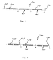
- Fig. 1 discloses a continuous-filament thread 100 comprising a continuous-filament thread body 110.
- the continuous-filament thread body 110 comprises a plurality of barbs 115 projecting from the continuous-filament thread body 110.
- the barbs 115 are arranged in a unidirectional disposition on the continuous-filament thread body 110.
- the continuous-filament thread body 110 comprises sections 120 having barbs - in the following referred to as barbed sections and sections 125 having no barbs - in the following referred to as barbless sections.
- the barbed sections 120 are interspaced by the barbless sections 125 and vice versa.
- the barbless sections 125 may advantageously serve as potential cutting areas for producing barbed sutures.
- barbed sutures bodies 135, 145 may be produced as integral entities, i.e. in one piece, having unidirectionally arranged barbs.
- the suture bodies 135, 145 may be also joined in a subsequent step yielding a barbed suture 130 comprising bidirectionally arranged barbs as depicted in figure 3a .
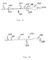
- Fig. 2 discloses a continuous-filament thread 200 comprising a continuous-filament thread body 210 comprising a plurality of barbs 215, which project from the continuous-filament thread body 210.
- the barbs 215 are arranged bidirectionally on the continuous-filament thread body 210.
- the continuous-filament thread body 210 comprises barbed sections 220 having barbs and barbless sections 225, wherein the barbed sections 220 are interspaced by the barbless sections 225 and vice versa.
- suture bodies 235, 245 having bidirectionally arranged barbs may be produced as integral entities, i.e. in one piece.
- the suture bodies 235, 245 may be joined in a subsequent step yielding a barbed suture comprising bidirectionally arranged barbs.
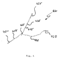
- Fig. 3a shows a combination of a surgical needle 128 (depicted as an arrow) and a barbed suture 130 that comprises two suture bodies 135, 145 that are joined by a common junction 138 such as a knot.
- Both suture bodies 135, 145 comprise a plurality of unidirectionally arranged barbs 115, wherein the barbs 115 of the first suture body 135 are orientated in the direction of the second suture body 145 and the barbs 115 of the second suture body 145 are orientated in the direction of the first suture body 135.
- the barbed suture 130 in total comprises bidirectionally arranged barbs.
- the barbed suture comprises barbed sections 120 and barbless sections 125.
- the barbless sections 125 are present around the common junction 138 and at the terminal sections 141, 143 of the suture 130.
- the terminal sections 141, 143 are attached to the surgical needle 128, preferably forming a suture loop as disclosed in figure 3 .
- the common junction 138 serves advantageously as a reference or control point for the surgeon in order to facilitate the identification of the suture's centre. Furthermore, the common junction 138 may serve as a control element in order to avoid an accidental sliding of the barbed suture 130 beyond its centre.
- Fig. 3b discloses a further embodiment of a surgical needle and a barbed suture combination.
- the terminal sections 141, 143 of the barbed suture 130 are attached to the surgical needles 128, 129, preferably forming a loop.
- the surgical needles 128,129 may be of the same type or may stand for different needle types. With respect to further details and advantages, reference is made in its entirety to the description belonging to figure 3a .
- Fig. 3c discloses a further embodiment of a surgical needle and a barbed suture combination.
- the barbed suture 130 comprises two suture bodies 135, 145 that are joined by a mutual junction 138. Both suture bodies 135, 145 comprise a section 120 of unidirectionally arranged barbs 115, wherein the barbed sections 120 are interspaced by a barbless section 125, wherein the barbless section 125 is around the mutual junction 138.
- the barbed suture 130 comprises terminal sections 141, 143 that are free of barbs and that are attached to the surgical needle 128.
- the suture bodies 135, 145 are twisted along the barbed sections 120.
- Fig. 3d discloses a further embodiment of a surgical needle and barbed suture combination.
- the barbed suture 130 comprises a suture body 135 having a plurality of unidirectionally arranged barbs 115.
- the barbs 115 are present one the suture body 135 in form of two unidirectional dispositions. In relation to one barb disposition, the other disposition is formed on the suture body 135 at approximately 180 ° in the circumferential direction and offset in relation to the first unidirectional disposition.
- the barbed suture 130 comprises a junction 138 such as a knot at one terminal section 139 of the suture body 135.
- the opposite terminal section 141 is attached to a surgical needle 128.
- Fig. 4 shows a further embodiment of a surgical needle and barbed suture combination.
- the barbed suture 430 comprises three suture bodies 435, 445, 455, wherein the suture bodies 435, 445, 455 comprise a plurality of barbs 415 and wherein the suture bodies 435, 445, 455 are joined by a mutual junction 438.
- the suture bodies 435, 445, 455 are roughly directed in the edges of a triangle.
- the mutual junction 438 may be a knot or as an alternative a T-fitting.
- the suture bodies 435, 445, 455 are attached to the surgical needles 428, 429, 431 as disclosed in
- Fig. 4 With respect to the surgical needles 428, 429, 431, needles of the same or a different type may be used. Furthermore, the suture bodies 435, 445, 455 may comprise barbed and/or unbarbed sections. It is further within the scope of the present invention that some of the suture bodies are free of barbs 415. With respect to further features and advantages, reference is made in its entirety to the previous figure descriptions.
- Fig. 5 shows a further embodiment of a surgical needle and barbed suture combination.
- the barbed suture 530 comprises four suture bodies 535, 545, 555, 565, wherein the suture bodies 535, 545, 555, 565 comprise a plurality of barbs 515 and wherein the suture bodies 535, 545, 555 are joined by a mutual junction 538.
- the suture bodies 535, 545, 555, 565 are roughly directed in the edges of a square.
- the mutual junction 538 may be a knot.
- the suture bodies are attached to the surgical needles 528, 529, 531, 532.
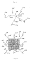
- Fig. 6 shows a star-like arranged barbed suture 630, wherein the barbs for sake of clearness are not depicted.
- the barbed suture comprises suture bodies 605, 635, 645, 655, 665, 675, 685, 695 being attached to the surgical needles 628, 629, 631, 632, 633, 634, 636, 637.
- the barbed suture 630 may be, by way of example, used to fix a medical mesh 647 in the body of the patient.
- a resistance element according to the present invention may also be used.
- a polydioxanone monofilament is extruded, passed through a quench bath and wound on a drum winder without drawing the fiber to its final length. Subsequently the undrawn fiber is passed through a cutting device to produce an undrawn, continuous monofilament having a regular pattern of unidirectional barbed sections followed by sections that have no barbs. Afterwards this continuous barbed monofilament is drawn to its final length by passing it through multistage drawing equipment, applying a 3-fold drawing ratio and then wound on a spool.
- the fiber is wound off the spool and cut in the middle of each unbarbed (barbless) section, resulting in an amount of monofilament strands having an unidirectional barbed section in the center and non-barbed sections at the ends of the strands.
Abstract
Description
- The present invention relates to a continuous-filament thread having a plurality of barbs, a method for producing a continuous-filament thread having a plurality of barbs, a barbed suture and a method for producing a barbed suture.
- Various surgical methods employing sutures have been used in the past for closing or binding together wounds in human or animal tissue. More specifically, the surgeon may use a surgical needle with an attached conventional suture to pierce the tissue alternately on opposing faces of the wound and thus sew the wound closed. Usually, the sutures are knotted in order to obtain a secure fixing in the tissue. Care has to be taken to ensure that the wounds to be closed are sutured with an optimal force at the wound margins. If the wound margins are sutured too loosely and too irregularly, for example, there is in principle a risk of increased scaring or dehiscence. By contrast, if the wound margins are sewed too strongly, there is a danger of the circulation of blood in the wound margins being restricted, which can result in necrotic changes in the surrounding tissue area.
- In addition to the risk of possible complications, in particular further surgical interventions, there is therefore always a degree of risk of the wound repair, based on knotting of sutures, leading to impaired healing and to unsatisfactory cosmetic results in the patients concerned. Another consideration is that several knots often have to overlap in order to achieve a secure knot hold. This entails introducing a large amount of material into the area of the wound, which may elicit tissue erosion and foreign-body reactions.
- Sutures which, in contrast to conventional sutures, do not have to be knotted have long been known under the term "barbed sutures". Since the time of their conception, barbed sutures have offered numerous advantages over closing wounds with conventional sutures. A barbed suture typically includes an elongated body that has spaced barbs which project from the body surface along the body length. The barbs are arranged on the elongate body in such a way that the suture can be pulled through the tissue along the direction of the barbs without any great resistance and without tissue trauma. When a pull is exerted in the opposite direction, however, the barbs stand upright and anchor themselves, and therefore also the suture, in the surrounding tissue area. This ensures that the suture cannot be pulled back through the incision channel. Thus, the main advantage of barbed sutures has been the provision of a non-slip attribute. Barbed sutures are described, for example, in the documents
US 3,123,077 A ,EP 1 559 266 B1 ,EP 1 560 683 B1 andEP 1 556 946 B1 . - With respect to barbed sutures, the barbs are often arranged in a symmetrical fashion on the suture. For instance, the barbs may be formed in a helical pattern on the sutures, wherein the helix has a defined twist direction, cut depth and cut distance. However, such a helical disposition of the barbs may lead to a coil of the suture depending on the length of the incision, which may have an adverse effect on the scaring.
- A further disadvantage that is associated with barbed sutures relates to their producing process. Normally, barbed sutures having distinct properties, in particular in view of barb geometry, have to be produced in an elaborate and time-consuming process.
- The object of the present invention is therefore to make available a barbed material including a barbed suture which avoids disadvantages known from the prior art. In particular, the barbed material according to the present invention should allow for a comfortable provision of barbed sutures having distinct properties depending on the wound to be closed by the barbed suture.
- Accordingly, the present invention provides a continuous-filament thread comprising a continuous-filament thread body comprising barbs, in particular a plurality of barbs. The barbs preferably project from the continuous-filament thread body.
- The term "continuous-filament thread" and "continuous-filament thread body", respectively as used according to the invention, preferably relates to a thread and thread body, respectively that is unprocessed at least in view of its length ("endless-filament thread" and "endless-filament thread body", respectively).
- The term "barbs" as used according to the invention encompasses at least one barb.
- The term "plurality of barbs" as used according to the invention encompasses at least two or more barbs.
- The term "thread" and "thread body", respectively as used according to the invention, may include a fibre, a yarn, a strand, a monofilament, in particular a pseudo-monofilament, or a multifilament, in particular a braided or intertwined multifilament.
- In principal the continuous-filament thread body may comprise a uniform barb configuration or a different or varying, in particular an alternating or a random barb configuration. The term "configuration" according to the invention is to be understood in its broadest sense and in particular encompasses the design, shape, geometry and/or disposition of the barbs. More specifically, the barbs may have a uniform or different or varying, in particular alternating or random, configuration in view of barb length, barb height, cutting depth, cutting distance, cutting angle, cutting angle offset and, combinations thereof. In view of producing barbed sutures having different or varying, in particular alternating or random, barb configurations, it is preferable that the continuous-filament thread body comprises a varying, in particular alternating or random, barb configuration along its length. Thus, a multiplicity of barbed sutures having distinct barb configurations may be produced from a single continuous-filament thread according to the present invention.
- It is especially preferred that continuous-filament thread body comprises a random barb configuration.
- In a further preferred embodiment, the barbs have a shape that is selected from the group consisting of escutcheon-shape, shield-shape, scale-shape, wedge-shape, thorn-shape, W-shape, arrow-shape, spike-shape, tin-shape, V-shape and, combinations thereof. Further, the barbs are preferably pointed or tapered at their free ends. Furthermore, the barbs may have a multi-tip configuration, in particular a twin-tip configuration. An example for barbs having a twin-tip configuration is the above mentioned W-shaped formation of barbs. Barbs having a twin-tip configuration may in particular be based on flat cuts into the continuous-filament thread body, preferably formed with a small angular offset and in small intervals from each other.
- In a further embodiment, the barbs are arranged in a uniform disposition on the continuous-filament thread body.
- However, in view of the production of different barbed sutures from a single continuous-filament thread according to the invention, it may be preferred that the barbs are arranged in different or varying, in particular alternating or, more preferable, random, dispositions on the continuous-filament thread body.
- More specifically, the barbs may have a disposition on the continuous-filament thread body that is selected from the group consisting of a row disposition, a staggered disposition, an overlapping disposition, an offset disposition, an offset and partially overlapping disposition, a zigzag disposition, a random or arbitrary disposition, a meander-like disposition, a serpentine-like disposition, a sinus-like disposition, a spiral disposition, a helical disposition, and combinations thereof.
- According to a further embodiment, the barbs are arranged in the form of left-handed and/or right-handed spirals and/or helices on the continuous-filament thread body. More specifically, left-handed and/or right-handed spirals and/or helices may be present on the continuous-filament thread body in a different or varying, in particular alternating or random, disposition. For example, a spiral or helical barb disposition having a different or varying, in particular alternating or random, spiral or helical twist, contributes to the reduction of suture coiling. Thus, adverse interactions between a tissue and a coiled suture may be significantly reduced, thereby enhancing wound healing.
- In a preferred embodiment, the barbs are arranged in a unidirectional disposition on the continuous-filament thread body. The term "unidirectional disposition" as used herein, relates to a barb disposition, wherein the barbs are orientated in the same direction on the continuous-filament thread body.
- More preferably, the barbs are arranged in a multidirectional, in particular bidirectional, disposition on the continuous-filament thread body. According to the invention, the term "multidirectional disposition" relates to a disposition of barbs, in which the barbs are oriented or aligned in multiple directions on the continuous-filament thread body. Accordingly, according to the invention, the term "bidirectional disposition" relates to a disposition of barbs, in which the barbs are oriented or aligned in two different directions. Preferably, the barbs are orientated or aligned in opposing directions. More preferably, seen in the longitudinal direction of the continuous-filament thread body, the barbs for a first continuous-filament thread body section are preferably formed in the direction of a second continuous-filament thread body section and, for the second continuous-filament thread body section, are formed in the direction of the first continuous-filament thread body section.
- The continuous-filament thread body may comprise in a further embodiment repeating units of unidirectionally arranged barbs.
- As an alternative or in combination, the continuous-filament thread body may comprise repeating units of multidirectionally arranged barbs. Preferably, the continuous-filament thread body comprises repeating units of bidirectionally arranged barbs. In particular, each unit may comprise a first section and a second section, wherein, seen in the longitudinal direction of the continuous-filament thread body, the barbs of the first section are orientated in the direction of the second section and the barbs of the second section are orientated in the direction of the first section.
- Generally, the continuous-filament thread body may comprise at least two, in particular two or three, multidirectional dispositions of barbs.
- In a further embodiment, the continuous-filament thread body may comprise at least two, in particular two, bidirectional dispositions of barbs on its surface. It is particularly preferable if, in relation to a first bidirectional disposition of barbs, a second bidirectional disposition of barbs is formed on the continuous-filament thread body at approximately 180° in the circumferential direction and preferably offset in relation to the first bidirectional disposition.
- It is also conceivable that the continuous-filament thread body comprises three bidirectional dispositions of barbs. In this case, it is preferable if, in relation to a first bidirectional disposition of barbs, a second bidirectional disposition of barbs is formed on the continuous-filament thread body at approximately 120° in the circumferential direction and preferably offset in relation to the first bidirectional disposition, which second bidirectional disposition of barbs is in turn formed at approximately 120° in the circumferential direction and preferably offset in relation to a third bidirectional disposition of barbs, such that the third bidirectional disposition of barbs is likewise formed at approximately 120° in the circumferential direction and preferably offset in relation to the first bidirectional disposition of barbs.
- It is further within the scope of the present invention that the continuous-filament thread body may comprise more than three, in particular four, five or six, multidirectional, in particular bidirectional, dispositions of barbs on the continuous-filament thread body.
- According to an especially preferred embodiment, the continuous-filament thread body comprises sections that are free of barbs, in the following also denoted as barbless sections. The barbless sections may generally serve as potentially cutting areas so as to obtain barbed sutures from the continuous-filament thread body of the present invention. Preferably, the barbless sections at least are also present in a barbed suture that is obtained from the continuous-filament thread. More specifically, the barbless sections may serve as junction areas for joining lengths or sections, in particular sutures bodies, obtained by cutting the continuous-filament thread body. Furthermore the barbless sections may serve as attachment areas for attaching medical instruments, in particular inserting instruments such as a surgical needle, and/or for attaching medical devices such as meshes to a barbed suture that may be obtained from the continuous filament thread. Furthermore, the barbless sections may advantageously facilitate the identification of the centre of a barbed suture that may be obtained from the continuous-filament thread.
- In a further embodiment, terminal ends of the continuous-filament thread body may be free of barbs.
- More specifically, the continuous-filament thread body may comprise a different or varying, in particular an alternating or a random, disposition of barbed sections and barbless sections.
- It is especially preferred that the continuous-filament thread body comprises sections having barbs that are interspaced by sections having no barbs. In other words, it is especially preferred that the continuous-filament thread body may comprise an alternating disposition of sections having barbs (barbed sections) and sections having no barbs (barbless sections). The barbed sections may comprise unidirectionally or multidirectionally, in particular bidirectionally, arranged barbs.
- According to a further preferred embodiment, the continuous-filament thread body is designed as a mass or solid continuous-filament thread body. This in particular means that the continuous-filament thread body is free of a lumen or the like. As already mentioned before, the continuous-filament thread body may be designed in the form of a fibre, yarn, strand, monofilament, pseudo-monofilament or multifilament, in particular braided or intertwined multifilament.
- In an alternative preferred embodiment, the continuous-filament thread body may be designed as a hollow continuous-filament thread body, in particular as a tubular continuous-filament thread body, preferably as continuous-tube or continuous-hose. The term "continuous-tube" and "continuous-hose", respectively preferably relates to a tube and hose, respectively that is unprocessed at least in view of its length. Preferably, the hollow continuous-filament thread body comprises a closed wall, wherein the continuous-filament thread body preferably comprises open ends. A hollow, in particular tubular, continuous-filament thread body may be produced, by way of example, by means of an extrusion process. The barbs may project into the interior and/or exterior of the hollow continuous-filament thread body. Particularly, the barbs may be designed as cuts into the hollow continuous-filament thread body, wherein the barbs preferably do not break through the wall of the hollow continuous-filament thread body. As an alternative or in combination, the barbs may be designed as breakthroughs, i.e. the barbs are formed completely breaking through the wall of the hollow continuous-filament thread body.
- Further, the continuous-filament thread body may not be limited in view of its cross section. In general, a circular cross section of the continuous-filament thread body is preferred. However, other cross-sectional shapes are likewise conceivable. For example, the continuous-filament thread body can have an oval, triangular, rosette-like, square, trapezoidal, rhomboid, pentagonal, hexagonal, star-shaped or cross-shaped cross section. Such cross-sectional shapes can readily be formed by means of suitable extrusions dies, which can be produced specific to a customer with any desired cross-sectional shape.
- In a further embodiment, the thread body may comprise at least one, in particular one, set of barbs. It may also be within the scope of the present invention that the barbs are configured in at least two, in particular two, three, four, five or more, sets, each set having a barb configuration different from the barb configuration of the other set.
- Preferably, the continuous-filament thread body is made from a material selected from the group consisting of a bio-absorbable material, a non-absorbable material, and combinations thereof. Typically, the continuous-filament thread body is made of a polymer. The term "polymer" as used according to the invention may include copolymers, in particular random copolymers, alternating copolymers, graft copolymers and/or block copolymers. Further, as used according to the invention, the term "copolymer" relates to a polymer that is composed of at least two different monomer units. Accordingly, it may be within the scope of the present invention that the continuous-filament thread body is also made from terpolymers, tetrapolymers or the like.
- Preferably, the continuous-filament thread body is made of a polyhydroxyalkanoate, a copolymer thereof or a mixture thereof. More specifically, the continuous-filament thread body is preferable made of a bio-absorbable material that is selected from the group consisting of polylactide, polyglycolide, polydioxanone, polytrimethylene carbonate, poly-ε-caprolactone, poly-3-hydroxybutyrate, poly-4-hydroxybutyrate, copolymers thereof and mixtures thereof.
- In another embodiment, the continuous-filament thread body is made of a non-absorbable material that is selected from the group consisting of polyamide, polyester such as polyethylene terephthalate, polypropylene terephthalate and/or polybutylene terephthalate, polyethylene, polypropylene, polyurethane, polytetrafluoroethylene, in particular expanded polytetrafluorethylene, polyvinylidene difluoride, polytetrafluoropropylene, polyhexafluoropropylene, polyetherester, copolymers thereof, and mixtures thereof.
- Furthermore, the continuous-filament thread body may comprise additives such as biological agents, medical agents, pharmaceutical agents, cells, and combinations thereof. Biological active agents may be selected from the group consisting of differentiation factors, growth factors, recruiting factors, adhesion factors, and combinations thereof. Appropriate growth factors may be selected from the group consisting of fibroblast growth factor (FGF), transforming growth factor (TGF), platelet derived growth factor (PDGF), epidermal growth factor (EGF), granulocyte-macrophage colony stimulation factor (GMCSF), vascular endothelial growth factor (VEGF), insuline-like growth factor (IGF), hepatocyte growth factor (HGF), interieucin-1 B (IL-1 B), interleucin-8 (IL-8), nerve growth factor (NGF), and combinations thereof. Medical and pharmaceutical agents, respectively may be selected from the group consisting of antimicrobial agents, in particular antibiotic agents, disinfecting agents, growth-promoting agents, anti-inflammatory agents, analgetic agents, odor-controlling agents, and mixtures thereof. Preferred cellular additives may be somatic cells, in particular autologous cells, like fibroblasts, chondrocytes and/or precursors cells, in particular stem cells, for example. Furthermore, such substances, like collagen and/or hyaluronic acid for example, may be particularly beneficial in the field of plastic surgery to achieve cosmetically satisfactory results, like a smoothing of wrinkles, for example.
- In a further embodiment, the continuous-filament thread body may be present in a drawn or undrawn state.
- In a further embodiment, the continuous-filament thread body may be present in a sterile form.
- Another aspect of the present invention refers to a method for producing a continuous-filament thread comprising a continuous-filament thread body comprising barbs, in particular a plurality of barbs, which preferably project from the continuous-filament thread body, wherein the barbs are cut into a barbless continuous-filament thread body, i.e. the barbs are cut into a continuous-filament thread body having no barbs.
- The barbs may be formed using any suitable method, including cutting, in particular mechanical cutting, injection molding, stamping, laser, and the like.
- Further, the barbs may be cut into an undrawn or into a drawn continuous-filament thread body.
- In a preferred embodiment, the barbs are cut in while the continuous-filament thread body is rotated. In another embodiment, the continuous-filament thread body is twisted prior to cutting in barbs and untwisted again after the barbs have been cut in. The embodiments described in this paragraph are advantageous in that a radial, in particular spiral-shaped or helical-shaped disposition of barbs may be generated on the continuous-filament thread body.
- For a cutting, in particular mechanical cutting, conventional cutting devices comprising a cutting bed, at least one cutting plate and holding or fixing elements such as vices, chucks, holding or clamping jaws, may be used. For mechanical cutting of the barbs, it is particularly preferable to use a cutting bed with a groove, wherein the groove is provided to receive the continuous-filament thread body that is to be cut. Depending on the depth of the groove, it is possible, when using at least one cutting plate, to specifically influence the cutting depth with which the barbs are cut into the continuous-filament thread body. This is because the at least one cutting plate is generally designed such that, by means thereof, cuts can be made only in the areas of the continuous-filament thread body, which protrude from the groove. This advantageously contributes to a safe cutting.
- With respect to laser, lasers that can be used, are in principle, gas lasers, for example CO2 lasers, and also solid-state lasers, for example, Nd:YAG lasers (neodymium-doped yttrium aluminium garnet lasers). A suitable laser cutting machine generally comprises a laser beam source, a beam guide, and at least movable focusing lens (concave mirror or positive lens). The beam leaving the beam source is either guided by fibre-optic cables for example in a Nd:YAG laser, or by a deflecting mirror, for example in a CO2 laser, to the machining lens which focuses the laser beam and in this way generates the power densities needed for the cutting, generally in the range of 106 to 109 W/cm2. Corresponding cutting laser methods are sufficiently known to a person skilled in the art, such that further details are not given here.
- With respect to a drawing of the continuous-filament thread body, such a drawing may be performed in a temperature range of between 20° and 80° C above the glass transition temperature of the thread body material. For instance, infrared radiation can be used, to generate a suitable heat for the drawing process. To draw the continuous-filament thread body, the thread body is usually guided across a roller system, so-called drawing frame, in which the rollers can have different speeds of rotation. Generally, each subsequent roller has a higher speed of rotation than the proceeding roller of the drawing system. As an alternative to the continuous drawing just described, it is also possible, according to the invention, to carry out intermittent drawing. For intermittent drawing, the thread body may be clamped between the clamping jaws of a tensioning device and then drawn. For drawing the continuous-filament thread body, a drawing ratio of between 2.5 and 8 and particularly of between 3 and 5 may be chosen.
- After the continuous-filament thread body has been drawn, the thread body can be subjected to various post-treatment steps. For this purpose, the continuous-filament thread body is generally tempered (heat-treated) in a vacuum or reduced pressure atmosphere. In this way, crystallinity of the continuous-filament thread body may be increased and the residual monomer content reduced. A further advantage afforded by a post-treatment of the continuous-filament thread body material is the reduced susceptibility to shrinkage.
- Another aspect of the present invention relates to a barbed suture comprising at least one elongate suture body comprising barbs, in particular a plurality of barbs, which preferably project from the at least one suture body. The barbed suture is preferably obtainable or obtained from a continuous-filament thread according to the present invention.
- The term "at least one suture body" includes one, two, three, four, five, six, seven eight or more suture bodies. Depending on the number of suture bodies it is within the scope of the invention that the barbed suture may, by way of example, be arranged as a linear barbed suture, as star-like barbed suture or as a branched, in particular dendrimer-like, barbed suture.
- In principal, the at least one suture body may comprise a uniform barb configuration or a different or varying, in particular an alternating or, more preferable, a random, barb configuration. More specifically, the barbs may have a uniform or different or varying, in particular alternating or random, configuration in view of barb design, barb geometry and/or barb shape, in particular in view of barb length, barb height, cutting depth, cutting distance, cutting angle, cutting angle offset and, combinations thereof.
- In a preferred embodiment, the barbs have a shape that is selected from the group consisting of escutcheon-shape, shield-shape, scale-shape, wedge-shape, thorn-shape, W-shape, arrow-shape, spike-shape, tin-shape, V-shape and, combinations thereof. Further, the barbs are preferably pointed or tapered at their free ends. Furthermore, the barbs may have a multi-tip configuration, in particular a twin-tip configuration. An example for barbs having a twin-tip configuration is the above mentioned W-shaped formation of barbs. Barbs having a twin-tip configuration may in particular be based on flat cuts into the at least one suture body, preferably formed with a small angular offset and in small intervals from each other.
- In a further embodiment, the barbs are arranged in a uniform disposition on the at least one suture body. However, different or varying, in particular alternating or random, dispositions may also be within the scope of the present invention.
- More specifically, the barbs may have a disposition on the at least one suture body that is selected from the group consisting of a row disposition, a staggered disposition, an overlapping disposition, an offset disposition, an offset and partially overlapping disposition, a zigzag disposition, a random or arbitrary disposition, a meander-like disposition, a serpentine-like disposition, a sinus-like disposition, a spiral disposition, a helical disposition, and combinations thereof.
- According to a further embodiment, the barbs are arranged in the form of left-handed and/or right-handed spirals and/or helices on the at least one suture body. More specifically, left-handed and/or right-handed spirals and/or helices may be present on the at least one suture body in a different or varying, in particular alternating or random, disposition. For example, a spiral or helical barb disposition having a different or varying, in particular alternating or random, spiral or helical twist, contributes to the reduction of suture coiling. Thus, adverse interactions between a tissue and a coiled suture may be significantly reduced, thereby enhancing wound healing.
- In a preferred embodiment, the barbs are arranged in a unidirectional disposition on the at least one suture body.
- More preferably, the barbs are arranged in a multidirectional, in particular bidirectional, disposition on the at least one suture body. Preferably, the barbs are orientated or aligned in opposing directions. More preferably, seen in the longitudinal direction of the at least one suture body, the barbs for a first suture body section are preferably formed in the direction of a second suture body section and, for the second suture body section, are formed in the direction of the first suture body section.
- The at least one suture body may comprise in a further embodiment repeating units of unidirectionally arranged barbs.
- As an alternative or in combination, the at least one suture body may comprise repeating units of multidirectionally arranged barbs. Preferably, the at least one suture body comprises repeating units of bidirectionally arranged barbs. In particular, each unit may comprise a first section and a second section, wherein, seen in the longitudinal direction of the at least one suture body, the barbs of the first section are orientated in the direction of the second section and the barbs of the second section are orientated in the direction of the first section.
- Generally, the at least one suture body may comprise at least two, in particular two or three, multidirectional dispositions of barbs.
- In a further embodiment, the at least one suture body may comprise at least two, in particular two, bidirectional dispositions of barbs on its surface. It is particularly preferable if, in relation to a first bidirectional disposition of barbs, a second bidirectional disposition of barbs is formed on the at least one suture body at approximately 180° in the circumferential direction and preferably offset in relation to the first bidirectional disposition.
- It is also conceivable that the at least one suture body may comprise three bidirectional dispositions of barbs. In this case, it is preferable if, in relation to a first bidirectional disposition of barbs, a second bidirectional disposition of barbs is formed on the at least one suture body at approximately 120° in the circumferential direction and preferably offset in relation to the first bidirectional disposition, which second bidirectional disposition of barbs is in turn formed at approximately 120° in the circumferential direction and preferably offset in relation to a third bidirectional disposition of barbs, such that the third bidirectional disposition of barbs is likewise formed at approximately 120° in the circumferential direction and preferably offset in relation to the first bidirectional disposition of barbs.
- The barbs may be in principle arranged user-defined on the at least one suture body. For instance, the barbs may be arranged in the centre of the at least one suture body.
- According to an especially preferred embodiment, the at least one suture body comprises sections that are free of barbs, in the following also denoted as barbless sections.
- More specifically, the at least one suture body may comprise a barbless section around the centre of the at least one suture body. In this embodiment, the barbless section may expediently serve as a control or reference section, which facilitates the identification of the barbed suture's centre. Further, the barbless section may serve as a control or reference section in order to avoid an accidental sliding of the at least one suture body beyond its centre into a tissue to be treated.
- Further, the at least one suture body may have at least one terminal section (terminal end), in particular one, two or, if appropriate, more than two terminal sections, that is free of barbs. These barbless sections may beneficially serve as attachment areas for attaching the at least one suture body to at least one further suture body. Furthermore, the barbless sections may serve as attachment areas for attaching medical instruments, in particular inserting instruments such as a surgical needle and/or for attaching medical devices such as meshes to the at least one suture body.
- In a further embodiment, the at least one suture body may comprise a different or varying disposition of barbed sections and barbless sections. Preferably, the at least one suture body comprises sections having barbs that are interspaced by sections having no barbs. More specifically, the at least one suture body may comprise an alternating disposition of sections having barbs and sections having no barbs. The barbed sections may comprise unidirectionally or multidirectionally, preferably bidirectionally, arranged barbs.
- More specifically, the at least one suture body may have a first barbless terminal section, which is followed by a barbed section, which followed by a barbless section, which is followed by a barbed section, which is followed by a second terminal section.
- According to a further preferred embodiment, the at least one suture body is designed as at least one mass or solid suture body. More specifically, the at least one suture body may be designed in the form of a fibre, yarn, strand, monofilament, pseudo-monofilament or multifilament, in particular braided or intertwined multifilament.
- In an alternative preferred embodiment, the at least one suture body may be designed as at least one hollow suture body, in particular as at least one tubular suture body. Preferably, the at least one hollow suture body comprises a closed wall. Preferably, the at least one hollow suture body comprises open ends. Hollow suture bodies according to the invention may be produced, by way of example, by means of an extrusion process. The barbs may project into the interior and/or exterior of the at least one hollow suture body. Preferably, the barbs protrude into the exterior of the at least one hollow suture body. Particularly, the barbs may be designed as cuts into the at least one hollow suture body, wherein the barbs do not break through the wall of the at least one hollow suture body. As an alternative or in combination, the barbs may be designed as breakthroughs, i.e. the barbs are formed completely breaking through the wall of the at least one hollow suture body. Hollow suture bodies according to the present invention may be used as self-anchoring delivery tubes, drainage tubes, catheters, drug delivery systems or the like.
- Further, the at least one suture body may not be limited in view of its cross section. In general, a circular cross section of the at least one suture body is preferred. However, other cross-sectional shapes are likewise conceivable. For example, the at least one suture body can have an oval, triangular, rosette-like, square, trapezoidal, rhomboid, pentagonal, hexagonal, star-shaped or cross-shaped cross section. Such cross-sectional shapes can readily be formed by means of suitable extrusions dies, which can be produced specific to a customer with any desired cross-sectional shape.
- In a further embodiment, the at least one suture body may comprise at least one, in particular one, set of barbs. It may also be within the scope of the present invention that the barbs are configured in at least two, in particular two, three, four, five or more, sets, each set having a barb configuration different from the barb configuration of the other set.
- Preferably, the at least one suture body is made from a material selected from the group consisting of a bio-absorbable material, a non-absorbable material, and combinations thereof. Typically, the at least one suture body is made of a polymer.
- Preferably, the at least one suture body is made of a polyhydroxyalkanoate, a copolymer thereof or a mixture thereof. More specifically, the at least one suture body is preferable made of a bio-absorbable material that is selected from the group consisting of polylactide, polyglycolide, polydioxanone, polytrimethylene carbonate, poly-ε-caprolactone, poly-3-hydroxybutyrate, poly-4-hydroxybutyrate, copolymers thereof and mixtures thereof.
- In another embodiment, the at least one suture body is made of a non-absorbable material that is selected from the group consisting of polyamide, polyester such as polyethylene terephthalate, polypropylene terephthalate and/or polybutylene terephthalate, polyethylene, polypropylene, polyurethane, polytetrafluoroethylene, in particular expanded polytetrafluorethylene, polyvinylidene difluoride, polytetrafluoropropylene, polyhexafluoropropylene, polyetherester, copolymers thereof, and mixtures thereof.
- Furthermore, the at least one suture body may comprise additives such as biological agents, medical agents, pharmaceutical agents, cells, and combinations thereof. Biological active agents may be selected from the group consisting of differentiation factors, growth factors, recruiting factors, adhesion factors, and combinations thereof. Appropriate growth factors may be selected from the group consisting of fibroblast growth factor (FGF), transforming growth factor (TGF), platelet derived growth factor (PDGF), epidermal growth factor (EGF), granulocyte-macrophage colony stimulation factor (GMCSF), vascular endothelial growth factor (VEGF), insuline-like growth factor (IGF), hepatocyte growth factor (HGF), interieucin-1 B (IL-1 B), interleucin-8 (IL-8), nerve growth factor (NGF), and combinations thereof. Medical and pharmaceutical agents, respectively may be selected from the group consisting of antimicrobial agents, in particular antibiotic agents, disinfecting agents, growth-promoting agents, anti-inflammatory agents, analgetic agents, odor-controlling agents, and mixtures thereof. Preferred cellular additives may be somatic cells, in particular autologous cells, like fibroblasts, chondrocytes and/or precursors cells, in particular stem cells, for example. Furthermore, such substances, like collagen and/or hyaluronic acid for example, may be particularly beneficial in the field of plastic surgery to achieve cosmetically satisfactory results, like a smoothing of wrinkles, for example.
- In a further embodiment, the at least one suture body may be present in a drawn or undrawn state.
- In a further embodiment, the at least one suture body may be present in a sterile form.
- It is further within the scope of the present invention, that at least one, in particular one, terminal section of the at least one suture body may be attached to a surgical needle.
- Further, the suture, in particular the at least one suture body, may comprise two terminal sections, wherein both terminal sections are attached to one surgical needle, preferably forming a loop.
- As an alternative, the suture, in particular the at least one suture body, may comprise two terminal sections, wherein each terminal section is attached to a surgical needle. In this embodiment, each terminal section may be attached to the same type of surgical needle or to a different type of surgical needle.
- Instead of the surgical needle mentioned in the above-described embodiments, other surgical instruments, in particular introducing or inserting instruments, like sheaths, tubes or the like, may be attached to the suture, in particular the at least one suture body.
- According to another embodiment, the suture, in particular the at least one suture body, comprises at least one junction, in particular at least one chemical or physical, in particular mechanical, junction and/or at least one resistance element. The term "at least one junction" may include one, two or more than two junctions. The term "at least one resistance element" may include one, two or more than two resistance elements. The term "resistance element" as used according to the invention preferably includes an element that contributes to an increased resistance, when the suture, in particular the at least one suture body, is pulled in and/or through a biological tissue.
- More specifically, the suture, in particular the at least one suture body, may comprise a junction and/or resistance element that is present in the centre or basically in the centre of the suture, in particular the at least one suture body. Such a junction and/or resistance element advantageously serve as a control or reference point or element for the surgeon so as to be able to identify the centre of the suture, in particular the at least one suture body. Further such a junction and/or resistance element expediently avoid an accidental sliding of the suture, in particular of the at least one suture body, beyond its centre, when the suture is pulled in and/or through a biological tissue.
- The at least one junction is preferably selected from the group consisting of a knot, a knob, a welded junction, in particular an ultrasonic welded junction, a soldered junction, a bonded junction, a joining flange, a T-fitting, and combinations thereof.
- With respect to a chemical, in particular bonding junction, such a junction may be achieved using a molten polymer and/or an adhesive. Further, a bonding junction may be achieved by using bio-absorbable materials, non-absorbable materials, and/or combinations thereof.
- According to a further embodiment, appendages of the junctions such as knot ears may be minimized, encapsulated or covered. For example, the appendages may be encapsulated or covered using a molten polymer and/or an adhesive. In particular, the appendages may be minimized to such an extent that they are no longer visible.
- The at least one resistance element is preferably selected from the group consisting of a mould such as a plate, a disc, a spherical, a ring, a circular mould, a pad, a pledget, a textile such as a woven fabric, braided fabric, knitted fabric, a mesh or the like, a joining flange, a T-fitting, and combinations thereof. The at least one resistance element may be further present in a miniaturized form.
- In a further embodiment, the barbs are orientated or aligned towards the at least one junction and/or towards the at least one resistance element.
- The at least one junction and/or the at least one resistance element may be made of a bio-absorbable material, non-absorbable material and/or combinations thereof. With respect to suitable materials, reference is made in its entirety to the previous description.
- In a further embodiment, the barbed suture comprises a plurality of suture bodies, wherein the suture bodies are preferably joined by at least one, in particular one, common junction and/or resistance element. The suture bodies may be made from a bio-absorbable material, a non absorbable material, and combinations thereof. Further, some of the suture bodies may be free of barbs.
- In an especially preferred embodiment, the barbed suture - as already mentioned is designed as a linear barbed suture. More specifically, the barbed suture may comprise at least two, in particular two, suture bodies that are joined by at least one, in particular one, common junction and/or resistance element. Preferably, each suture body comprises an unidirectional or a multidirectional, in particular a bidirectional, disposition of barbs. More preferably, suture sections comprising an unidirectional or multidirectional, in particular bidirectional, disposition of barbs may be interspaced by barbless suture sections. More preferably, the suture comprises a barbless section around the common junction and/or resistance element. Further, it is preferred that the suture comprises terminal sections that are free of barbs. With respect to further details and advantages, in particular in view of the junction and/or resistance element, reference is made in its entirety to the previous description.
- In case that the suture comprises more than two suture bodies, the barbed suture may be arranged in a non-linear, in particular in a star-like or branched, preferably dendrimer-like, fashion. In particular, the suture bodies may extend radially from a common junction and/or resistance element. With respect to further details and advantages, in particular in view of the junction and/or resistance element, reference is made in its entirety to the previous description.
- In a further embodiment, the suture, in a particular the at least suture body, comprises a marking, preferably in the form of a junction and/or resistance element, preferably for locating the centre of the suture, in particular for locating the centre of the at least one suture body. With respect to further details and advantages, in particular in view of the junction and/or resistance element, reference is made in its entirety to the previous description.
- Further, the barbed suture, in particular the at least one suture body, may comprise a resistance element, in particular a stop element such as a knot, at one terminal section of the suture, in particular the at least one suture body. In particular, the suture, in particular the at least one suture body, may also comprise a mechanical junction such as a joining flange or a T-fitting at a terminal section of the suture, in particular the at least one suture body.
- Preferably, the suture may comprise at least one mass or solid suture body. This in particular means that the at least one suture body is free of a lumen or the like. In particular, the at least one suture body may be designed as a fibre, monofilament, pseudomonofilament or multifilament, in particular as a braided or intertwined multifilament.
- As an alternative, the suture may comprise at least one hollow suture body, in particular at least one tubular or hose-like suture body. The at least one hollow suture body preferably comprises a closed wall encasing a lumen. Further, the at least one hollow suture body may comprise open ends. The barbs may be designed as cuts into the at least one hollow suture body, wherein the cuts do not break through the wall of the at least one hollow suture body. As an alternative or in combination, the barbs may be designed as breakthroughs, i.e. are formed completely breaking through the wall of the at least one hollow suture body. Further, the barbs may protrude into the interior and/or exterior, preferably exterior, of the at least one hollow suture body. A barbed suture comprising at least one hollow, in particular at least one tubular or hose-like, suture body may be used as self-anchoring delivery tubes, drainage tubes, catheters, drug-release systems or the like.
- The barbed suture according to the invention may generally be used as a self-anchoring or knotless suture, which is due to the barbs that serve as anchoring structures towards biological, in particular human and/or animal, tissue. The barbed suture according to the invention is in particular suitable for connecting and/or adaption of biological tissues. The tissue may include hard tissue like bone or cartilage as well as soft tissue like connective tissue. The tissues can be, for example, skin, fat, fascia, bones, muscles, organs, nerves, blood vessels, connective tissues, tendons or ligaments. The barbed suture may be in particular used in the field of endoscopic surgery, in particular laparoscopic surgery, microsurgery and/or plastic surgery. In the field of plastic surgery, the barbed suture may be employed for eye brow lifting and/or skin lining.
- Furthermore, the barbed suture according to the invention may be used for fixing medical devices such as medical meshes, in particular hernia meshes, prolaps meshes and/or urinary incontinence meshes. In order to support the fixation of medical devices, the barbed suture, in particular several barbed sutures, according to the invention may be fixed to an fixation means like a ring.
- Another aspect of the invention refers to a method for producing a barbed suture comprising at least one elongate suture body comprising barbs, in particular a plurality of barbs, which preferably project from the at least one suture body, wherein a continuous-filament thread comprising a continuous-filament thread body comprising barbs, in particular a plurality of barbs, which preferably project from the continuous-filament thread body, is cut into lengths or sections, in particular suture bodies.
- In a further embodiment, two or more of the cut lengths or sections, in particular suture bodies, are joined by a junction and/or resistance element, in particular a common junction and/or resistance element. With respect to further details and advantages of the method, reference is made in its entirety to the previous description.
- Another aspect of the invention relates to a surgical instrument, in particular surgical needle, and suture combination comprising a barbed suture according to the present invention. With respect to further details and advantages of the combination, in particular with respect to the barbed suture, reference is made in its entirety to the previous description.
- Further features of the invention will become clear from the following description of the drawings and from the example in conjunction with the dependent claims. The individual features can be realized either singly or severally in combination in one embodiment of the invention. The drawings and the example serve merely for illustration and better understanding of the invention and are not to be understood as in any way limiting the invention.
- The schematic figures show:
- Fig. 1
- an embodiment of the continuous-filament thread according to the invention,
- Fig. 2
- a further embodiment of the continuous-filament thread according to the invention,
- Fig. 3a
- an embodiment of the barbed suture and the surgical needle and barbed suture combination, respectively according to the invention,
- Fig. 3b
- a further embodiment of the barbed suture and the surgical needle and barbed suture combination, respectively according to the invention,
- Fig. 3c
- a further embodiment of the barbed suture and surgical needle and barbed suture combination, respectively according to the invention,
- Fig. 3d
- a further embodiment of the barbed suture and surgical needle and barbed suture combination, respectively according to the invention,
- Fig. 4
- a further embodiment of the barbed suture and surgical needle and barbed suture combination, respectively according to the invention,
- Fig. 5
- further embodiment of the barbed suture and surgical needle and barbed suture combination, respectively according to the invention,
- Fig. 6
- a field of application for an embodiment of the surgical needle and barbed suture combination according to the invention.
-
Fig. 1 discloses a continuous-filament thread 100 comprising a continuous-filament thread body 110. The continuous-filament thread body 110 comprises a plurality ofbarbs 115 projecting from the continuous-filament thread body 110. Thebarbs 115 are arranged in a unidirectional disposition on the continuous-filament thread body 110. More specifically, the continuous-filament thread body 110 comprisessections 120 having barbs - in the following referred to as barbed sections andsections 125 having no barbs - in the following referred to as barbless sections. Thebarbed sections 120 are interspaced by thebarbless sections 125 and vice versa. Thebarbless sections 125 may advantageously serve as potential cutting areas for producing barbed sutures. For example, by cutting the continuous-filament thread body 110 at the dotted positions a-c,barbed sutures bodies suture bodies barbed suture 130 comprising bidirectionally arranged barbs as depicted infigure 3a . -
Fig. 2 discloses a continuous-filament thread 200 comprising a continuous-filament thread body 210 comprising a plurality ofbarbs 215, which project from the continuous-filament thread body 210. Thebarbs 215 are arranged bidirectionally on the continuous-filament thread body 210. More specifically, the continuous-filament thread body 210 comprisesbarbed sections 220 having barbs and barbless sections 225, wherein thebarbed sections 220 are interspaced by the barbless sections 225 and vice versa. By cutting the continuous-filament thread 210 at the dotted positions a-c,suture bodies suture bodies -
Fig. 3a shows a combination of a surgical needle 128 (depicted as an arrow) and abarbed suture 130 that comprises twosuture bodies common junction 138 such as a knot. Bothsuture bodies barbs 115, wherein thebarbs 115 of thefirst suture body 135 are orientated in the direction of thesecond suture body 145 and thebarbs 115 of thesecond suture body 145 are orientated in the direction of thefirst suture body 135. Thus, thebarbed suture 130 in total comprises bidirectionally arranged barbs. - The barbed suture comprises
barbed sections 120 andbarbless sections 125. Thebarbless sections 125 are present around thecommon junction 138 and at theterminal sections suture 130. Theterminal sections surgical needle 128, preferably forming a suture loop as disclosed infigure 3 . - The
common junction 138 serves advantageously as a reference or control point for the surgeon in order to facilitate the identification of the suture's centre. Furthermore, thecommon junction 138 may serve as a control element in order to avoid an accidental sliding of thebarbed suture 130 beyond its centre. -
Fig. 3b discloses a further embodiment of a surgical needle and a barbed suture combination. Theterminal sections barbed suture 130 are attached to thesurgical needles 128, 129, preferably forming a loop. The surgical needles 128,129 may be of the same type or may stand for different needle types. With respect to further details and advantages, reference is made in its entirety to the description belonging tofigure 3a . -
Fig. 3c discloses a further embodiment of a surgical needle and a barbed suture combination. Thebarbed suture 130 comprises twosuture bodies mutual junction 138. Bothsuture bodies section 120 of unidirectionally arrangedbarbs 115, wherein thebarbed sections 120 are interspaced by abarbless section 125, wherein thebarbless section 125 is around themutual junction 138. Furthermore, thebarbed suture 130 comprisesterminal sections surgical needle 128. Besides, thesuture bodies barbed sections 120. With respect to further details and advantages, reference is made in its entirety to the description belonging tofigure 3a . -
Fig. 3d discloses a further embodiment of a surgical needle and barbed suture combination. Thebarbed suture 130 comprises asuture body 135 having a plurality of unidirectionally arrangedbarbs 115. Thebarbs 115 are present one thesuture body 135 in form of two unidirectional dispositions. In relation to one barb disposition, the other disposition is formed on thesuture body 135 at approximately 180 ° in the circumferential direction and offset in relation to the first unidirectional disposition. Thebarbed suture 130 comprises ajunction 138 such as a knot at oneterminal section 139 of thesuture body 135. The oppositeterminal section 141 is attached to asurgical needle 128. With respect to further details and advantages, reference is made in its entirety to the description belonging tofigure 3a . -
Fig. 4 shows a further embodiment of a surgical needle and barbed suture combination. Thebarbed suture 430 comprises threesuture bodies suture bodies barbs 415 and wherein thesuture bodies mutual junction 438. Thesuture bodies mutual junction 438 may be a knot or as an alternative a T-fitting. Thesuture bodies surgical needles -
Fig. 4 . With respect to thesurgical needles suture bodies barbs 415. With respect to further features and advantages, reference is made in its entirety to the previous figure descriptions. -
Fig. 5 shows a further embodiment of a surgical needle and barbed suture combination. Thebarbed suture 530 comprises four suture bodies 535, 545, 555, 565, wherein the suture bodies 535, 545, 555, 565 comprise a plurality ofbarbs 515 and wherein the suture bodies 535, 545, 555 are joined by amutual junction 538. The suture bodies 535, 545, 555, 565 are roughly directed in the edges of a square. Themutual junction 538 may be a knot. The suture bodies are attached to thesurgical needles -
Fig. 6 shows a star-like arrangedbarbed suture 630, wherein the barbs for sake of clearness are not depicted. The barbed suture comprisessuture bodies surgical needles barbed suture 630 may be, by way of example, used to fix amedical mesh 647 in the body of the patient. - Instead of the junction described in the above figure descriptions, a resistance element according to the present invention may also be used.
- A polydioxanone monofilament is extruded, passed through a quench bath and wound on a drum winder without drawing the fiber to its final length. Subsequently the undrawn fiber is passed through a cutting device to produce an undrawn, continuous monofilament having a regular pattern of unidirectional barbed sections followed by sections that have no barbs. Afterwards this continuous barbed monofilament is drawn to its final length by passing it through multistage drawing equipment, applying a 3-fold drawing ratio and then wound on a spool. In a next step, the fiber is wound off the spool and cut in the middle of each unbarbed (barbless) section, resulting in an amount of monofilament strands having an unidirectional barbed section in the center and non-barbed sections at the ends of the strands.
- These strands are then used to produce a star shaped fixation device for surgical meshes. Therefore four of these unidirectional strands as mentioned above are connected on one end by a knot, in a way that the directions of the barbs of the respective fibres points towards the knot. In a second step the other free fibre ends are attached to a needle resulting in the desired device (see
Figure 5 ).
Claims (16)
- A continuous-filament thread (100; 200) comprising a continuous-filament thread body (110; 210) comprising a plurality of barbs (115; 215) preferably projecting from the thread body (110; 210).
- The continuous-filament thread (100; 200) according to claim 1, characterized in that the thread body (110; 210) comprises a uniform barb configuration or a random barb configuration, in particular in view of barb design, barb geometry and/or barb shape, wherein the barbs preferably have a shape that is selected from the group consisting of escutcheon-shape, shield-shape, scale-shape, wedge-shape, thorn-shape, W-shape, arrow-shape, spike-shape, tin-shape V-shape and, combinations thereof.
- The continuous-filament thread (100; 200) according to claim 1 or 2, characterized in that the barbs (115; 215) are arranged in a uniform disposition or in a random disposition on the continuous-filament thread body (110; 210), wherein the disposition is preferably selected from the group consisting of a row disposition, a staggered disposition, an overlapping disposition, an offset disposition, an offset and partially overlapping disposition, a zigzag disposition, a random or arbitrary disposition, a meander-like disposition, a serpentine-like disposition, a sinus-like disposition, a spiral disposition, a helical disposition, and combinations thereof.
- The continuous-filament thread (100; 200) according to one of the preceding claims, characterized in that the barbs (115; 215) are arranged in a unidirectional disposition or in a multidirectional, preferably bidirectional, disposition on the continuous-filament thread body (110; 210), wherein the continuous-filament thread body preferably comprises repeating units of unidirectional or multidirectional, preferably bidirectional, arranged barbs (115; 215).
- The continuous-filament thread (100; 200) according to one of the preceding claims, characterized in that the continuous-filament thread body (110; 210) comprises sections (125; 225) that are free of barbs.
- The continuous-filament thread (100; 200) according to one of the preceding claims, characterized in that the continuous-filament thread body (110; 210) comprises sections (120; 220) having barbs that are interspaced by sections (125; 225) having no barbs.
- The continuous-filament thread (100; 200) according to one of the preceding claims, characterized in that the continuous-filament thread body (110; 210) is a mass thread body.
- The continuous-filament thread (100; 200) according to one of the claims 1 to 6, characterized in that the continuous-filament thread body (110; 210) is a hollow continuous-filament thread body, in particular a tubular continuous-filament thread body.
- A barbed suture (130; 430; 530; 630) comprising at least one elongate suture body (135; 145; 235; 245; 435; 445; 455; 535; 545; 555; 565; 605; 635; 645; 655; 665; 675; 685; 695) comprising barbs (115; 415; 515), in particular a plurality of barbs (115; 415; 515), which preferably project from the at least one suture body, preferable obtainable or obtained from a continuous-filament thread (100; 200) according to one of the claims 1 to 8.
- The barbed suture (130; 430; 530; 630) according to claim 9, characterized in that the barbs (115; 415; 515) are arranged in a unidirectional or multidirectional, preferably bidirectional, disposition, on the suture (130; 430; 530; 630), in particular on the at least one suture body (135; 145; 235; 245; 435; 445; 455; 535; 545; 555; 565; 605; 635; 645; 655; 665; 675; 685; 695).
- The barbed suture (130; 430; 530; 630) according to claim 9 or 10, characterized in that the at least one suture body (135; 145; 235; 245; 435; 445; 455; 535; 545; 555; 565; 605; 635; 645; 655; 665; 675; 685; 695) comprises sections (125) that are free of barbs.
- The barbed suture (130; 430; 530; 630) according to one of the claims 9 to 11, characterized in that the suture comprises sections (120) having barbs that are interspaced by sections (125) having no barbs.
- The barbed suture (130; 430; 530; 630) according to one of the claims 9 to 12, characterized in that the suture comprises at least one junction (138; 438; 538; 638), in particular at least one chemical or physical, in particular mechanical, junction, preferably selected from the group consisting of a knot, a knob, a welded junction, in particular an ultrasonic welded junction, a soldered junction, a bonded junction, a joining flange, a T-fitting, and combinations thereof.
- The barbed suture (130; 430; 530; 630) according to one of the claims 9 to 13, characterized in that the suture comprises a junction (138; 438; 538; 638) that is in the centre or basically in the centre of the suture.
- The barbed suture (130; 430; 530; 630) according to one of the claims 9 to 14, characterized in that the suture comprises a plurality of suture bodies (135; 145; 235; 245; 435; 445; 455; 535; 545; 555; 565; 605; 635; 645; 655; 665; 675; 685; 695), wherein the suture bodies are preferably joined by a common junction (138; 438; 538; 638).
- A surgical instrument, in particular surgical needle (128; 129; 428; 429; 431; 528; 529; 531; 532; 628, 629; 631; 632; 633; 634; 636; 637), and surgical suture combination comprising a barbed suture (130; 430; 530; 630) according to one of the claims 9 to 15
Priority Applications (3)
| Application Number | Priority Date | Filing Date | Title |
|---|---|---|---|
| ES10162574T ES2875830T3 (en) | 2010-05-11 | 2010-05-11 | Use of a continuous filament thread with a plurality of barbs for the production of sutures |
| EP10162574.7A EP2386252B1 (en) | 2010-05-11 | 2010-05-11 | Use of a continuous-filament thread having a plurality of barbs for the production of sutures |
| US13/104,085 US20110282386A1 (en) | 2010-05-11 | 2011-05-10 | Continuous-filament thread having a plurality of barbs and a barbed suture |
Applications Claiming Priority (1)
| Application Number | Priority Date | Filing Date | Title |
|---|---|---|---|
| EP10162574.7A EP2386252B1 (en) | 2010-05-11 | 2010-05-11 | Use of a continuous-filament thread having a plurality of barbs for the production of sutures |
Publications (2)
| Publication Number | Publication Date |
|---|---|
| EP2386252A1 true EP2386252A1 (en) | 2011-11-16 |
| EP2386252B1 EP2386252B1 (en) | 2021-04-07 |
Family
ID=42371954
Family Applications (1)
| Application Number | Title | Priority Date | Filing Date |
|---|---|---|---|
| EP10162574.7A Active EP2386252B1 (en) | 2010-05-11 | 2010-05-11 | Use of a continuous-filament thread having a plurality of barbs for the production of sutures |
Country Status (3)
| Country | Link |
|---|---|
| US (1) | US20110282386A1 (en) |
| EP (1) | EP2386252B1 (en) |
| ES (1) | ES2875830T3 (en) |
Cited By (18)
| Publication number | Priority date | Publication date | Assignee | Title |
|---|---|---|---|---|
| WO2013081904A1 (en) * | 2011-11-30 | 2013-06-06 | Ethicon, Inc. | Tongue suspension device and method |
| US8783258B2 (en) | 2008-12-01 | 2014-07-22 | Ethicon, Inc. | Implant systems and methods for treating obstructive sleep apnea |
| US8813754B2 (en) | 2009-02-17 | 2014-08-26 | Ethicon, Inc. | Magnetic implants and methods for treating an oropharyngeal condition |
| US8905033B2 (en) | 2011-09-28 | 2014-12-09 | Ethicon, Inc. | Modular tissue securement systems |
| US8915252B2 (en) | 2008-12-01 | 2014-12-23 | Ethicon, Inc. | Implant systems and methods for treating obstructive sleep apnea |
| EP2763600A4 (en) * | 2011-09-30 | 2015-07-29 | Covidien Lp | Hernia repair device and method |
| US9144511B2 (en) | 2008-08-14 | 2015-09-29 | Ethicon, Inc. | Methods and devices for treatment of obstructive sleep apnea |
| US9161855B2 (en) | 2011-10-24 | 2015-10-20 | Ethicon, Inc. | Tissue supporting device and method |
| US9173766B2 (en) | 2012-06-01 | 2015-11-03 | Ethicon, Inc. | Systems and methods to treat upper pharyngeal airway of obstructive sleep apnea patients |
| US9326886B2 (en) | 2009-10-29 | 2016-05-03 | Ethicon, Inc. | Fluid filled implants for treating obstructive sleep apnea |
| EP2929849A4 (en) * | 2012-12-05 | 2016-07-20 | Jacobs Medical Inc Y | Apparatus for inserting surgical thread, and surgical procedure kit for inserting surgical thread comprising same |
| US9480473B2 (en) | 2011-12-27 | 2016-11-01 | Y.Jacobs Medical Inc. | Knotless suture, and kit containing same |
| US9808234B2 (en) | 2011-03-07 | 2017-11-07 | Y. Jacobs Medical Inc. | Suture thread |
| US9877862B2 (en) | 2009-10-29 | 2018-01-30 | Ethicon, Inc. | Tongue suspension system with hyoid-extender for treating obstructive sleep apnea |
| US9974683B2 (en) | 2009-10-30 | 2018-05-22 | Ethicon, Inc. | Flexible implants having internal volume shifting capabilities for treating obstructive sleep apnea |
| US10178990B2 (en) | 2012-12-05 | 2019-01-15 | Y. Jacobs Medical Inc. | Apparatus for inserting surgical thread, and surgical procedure kit for inserting surgical thread comprising same |
| US10226320B2 (en) | 2013-12-06 | 2019-03-12 | Y.Jacobs Medical Inc. | Apparatus for inserting medical tube and surgical procedure kit for inserting medical tube, having same |
| US10470760B2 (en) | 2011-12-08 | 2019-11-12 | Ethicon, Inc. | Modified tissue securement fibers |
Families Citing this family (13)
| Publication number | Priority date | Publication date | Assignee | Title |
|---|---|---|---|---|
| KR101057377B1 (en) * | 2011-03-24 | 2011-08-17 | 한스바이오메드 주식회사 | Medical suture with micro cogs on the surface and producing method for the same |
| WO2013126234A1 (en) * | 2012-02-20 | 2013-08-29 | Dr7 Innovations, Llc | Locking suture |
| WO2014085363A1 (en) * | 2012-11-30 | 2014-06-05 | Covidien Lp | Looped tissue fixation device |
| WO2014134525A1 (en) * | 2013-03-01 | 2014-09-04 | Kent Island Holdings LLC | Locking suture |
| JP6313450B2 (en) | 2013-08-29 | 2018-04-18 | テレフレックス メディカル インコーポレイテッド | High strength multi-component suture |
| KR101534814B1 (en) * | 2015-03-05 | 2015-07-08 | 심길섭 | Mesh assembly |
| EP3085820B1 (en) | 2015-04-22 | 2017-12-20 | Sofradim Production | A method for forming a barbed suture and the barbed suture thus obtained |
| EP3085332B1 (en) | 2015-04-23 | 2019-02-27 | Sofradim Production | Package for a surgical mesh |
| KR101825878B1 (en) * | 2017-05-12 | 2018-02-06 | 장철호 | Needle apparatus for reposition surgery of orbital fat |
| CN111432749B (en) | 2017-10-19 | 2023-04-04 | C.R.巴德公司 | Self-gripping hernia prosthesis |
| US11272924B2 (en) | 2018-07-18 | 2022-03-15 | Arthrex, Inc. | Knotless closure sutures and methods of tissue fixation |
| US11224419B2 (en) * | 2019-06-28 | 2022-01-18 | Cilag Gmbh International | Bi-directional barbed suture with tailored suture segments |
| WO2024033763A1 (en) * | 2022-08-10 | 2024-02-15 | Covidien Lp | Looped suture devices and methods of forming looped suture devices |
Citations (7)
| Publication number | Priority date | Publication date | Assignee | Title |
|---|---|---|---|---|
| US3123077A (en) | 1964-03-03 | Surgical suture | ||
| EP1559266B1 (en) | 2002-09-30 | 2007-08-15 | Quill Medical, Inc. | Barbed suture in combination with surgical needle |
| EP1560683B1 (en) | 2002-09-30 | 2007-08-15 | Quill Medical, Inc. | Barbed sutures |
| FR2914178A1 (en) * | 2007-03-27 | 2008-10-03 | Cie De Rech En Composants Impl | Reinforcement implantable prosthesis i.e. parietal prosthesis, for e.g. anesthesia patient, has fixation unit passed via attachment orifice and supported against biological tissue at periphery of orifice to form anti-return unit |
| US20090099597A1 (en) * | 2007-10-12 | 2009-04-16 | Isse Nicanor G | Suture assembly with tissue engaging elements |
| DE102007058256A1 (en) * | 2007-11-26 | 2009-05-28 | Aesculap Ag | Surgical thread mesh |
| EP1556946B1 (en) | 2002-10-28 | 2011-12-14 | Commissariat à l'Énergie Atomique et aux Énergies Alternatives | Magnetostatic wave device based on thin metal films, method for making same and application to devices for processing microwave signals |
Family Cites Families (16)
| Publication number | Priority date | Publication date | Assignee | Title |
|---|---|---|---|---|
| FR2084475A5 (en) * | 1970-03-16 | 1971-12-17 | Brumlik George | |
| US6241747B1 (en) * | 1993-05-03 | 2001-06-05 | Quill Medical, Inc. | Barbed Bodily tissue connector |
| US6270517B1 (en) * | 2000-02-04 | 2001-08-07 | Gregory R. Brotz | Suture assembly and method |
| US6848152B2 (en) * | 2001-08-31 | 2005-02-01 | Quill Medical, Inc. | Method of forming barbs on a suture and apparatus for performing same |
| US20030149447A1 (en) * | 2002-02-01 | 2003-08-07 | Morency Steven David | Barbed surgical suture |
| DE102004047974A1 (en) * | 2004-10-01 | 2006-04-06 | Ethicon Gmbh | Surgical hook |
| WO2007131019A2 (en) * | 2006-05-04 | 2007-11-15 | Ethicon, Inc. | Tissue holding devices and methods for making the same |
| WO2007133103A1 (en) * | 2006-05-16 | 2007-11-22 | Marlen Andreevich Sulamanidze | Surgical suture material and a method to the use thereof |
| US20080281357A1 (en) * | 2007-05-09 | 2008-11-13 | An-Min Jason Sung | Looped tissue-grasping device |
| EP2222233B1 (en) * | 2007-12-19 | 2020-03-25 | Ethicon, LLC | Self-retaining sutures with heat-contact mediated retainers |
| ES2602570T3 (en) * | 2008-01-30 | 2017-02-21 | Ethicon Llc | Apparatus and method for forming self-retaining sutures |
| EP2249712B8 (en) * | 2008-02-21 | 2018-12-26 | Ethicon LLC | Method and apparatus for elevating retainers on self-retaining sutures |
| WO2009132284A2 (en) * | 2008-04-24 | 2009-10-29 | Angiotech Pharmaceuticals, Inc. | Shape-memory self-retaining sutures, methods of manufacture, and methods of use |
| DE102008057213A1 (en) * | 2008-11-06 | 2010-05-12 | Aesculap Ag | Medical device product, a surgical kit and a manufacturing process for the medical device product |
| DE102009020901A1 (en) * | 2009-05-08 | 2010-11-11 | Aesculap Ag | Coated thread with anchoring structures for anchoring in biological tissues |
| DE102009020897A1 (en) * | 2009-05-08 | 2010-11-11 | Aesculap Ag | Thread with coated anchoring structures for anchoring in biological tissues and a method for its production |
-
2010
- 2010-05-11 ES ES10162574T patent/ES2875830T3/en active Active
- 2010-05-11 EP EP10162574.7A patent/EP2386252B1/en active Active
-
2011
- 2011-05-10 US US13/104,085 patent/US20110282386A1/en not_active Abandoned
Patent Citations (7)
| Publication number | Priority date | Publication date | Assignee | Title |
|---|---|---|---|---|
| US3123077A (en) | 1964-03-03 | Surgical suture | ||
| EP1559266B1 (en) | 2002-09-30 | 2007-08-15 | Quill Medical, Inc. | Barbed suture in combination with surgical needle |
| EP1560683B1 (en) | 2002-09-30 | 2007-08-15 | Quill Medical, Inc. | Barbed sutures |
| EP1556946B1 (en) | 2002-10-28 | 2011-12-14 | Commissariat à l'Énergie Atomique et aux Énergies Alternatives | Magnetostatic wave device based on thin metal films, method for making same and application to devices for processing microwave signals |
| FR2914178A1 (en) * | 2007-03-27 | 2008-10-03 | Cie De Rech En Composants Impl | Reinforcement implantable prosthesis i.e. parietal prosthesis, for e.g. anesthesia patient, has fixation unit passed via attachment orifice and supported against biological tissue at periphery of orifice to form anti-return unit |
| US20090099597A1 (en) * | 2007-10-12 | 2009-04-16 | Isse Nicanor G | Suture assembly with tissue engaging elements |
| DE102007058256A1 (en) * | 2007-11-26 | 2009-05-28 | Aesculap Ag | Surgical thread mesh |
Cited By (29)
| Publication number | Priority date | Publication date | Assignee | Title |
|---|---|---|---|---|
| US9144511B2 (en) | 2008-08-14 | 2015-09-29 | Ethicon, Inc. | Methods and devices for treatment of obstructive sleep apnea |
| US8783258B2 (en) | 2008-12-01 | 2014-07-22 | Ethicon, Inc. | Implant systems and methods for treating obstructive sleep apnea |
| US8915252B2 (en) | 2008-12-01 | 2014-12-23 | Ethicon, Inc. | Implant systems and methods for treating obstructive sleep apnea |
| US8813754B2 (en) | 2009-02-17 | 2014-08-26 | Ethicon, Inc. | Magnetic implants and methods for treating an oropharyngeal condition |
| US9877862B2 (en) | 2009-10-29 | 2018-01-30 | Ethicon, Inc. | Tongue suspension system with hyoid-extender for treating obstructive sleep apnea |
| US9326886B2 (en) | 2009-10-29 | 2016-05-03 | Ethicon, Inc. | Fluid filled implants for treating obstructive sleep apnea |
| US9974683B2 (en) | 2009-10-30 | 2018-05-22 | Ethicon, Inc. | Flexible implants having internal volume shifting capabilities for treating obstructive sleep apnea |
| US11103230B2 (en) | 2011-03-07 | 2021-08-31 | Y.Jacobs Medical Inc. | Suture thread |
| US9848865B2 (en) | 2011-03-07 | 2017-12-26 | Y.Jacobs Medical Inc. | Suture thread |
| US9808234B2 (en) | 2011-03-07 | 2017-11-07 | Y. Jacobs Medical Inc. | Suture thread |
| US9592046B2 (en) | 2011-09-28 | 2017-03-14 | Ethicon, Inc. | Modular tissue securement systems |
| US8905033B2 (en) | 2011-09-28 | 2014-12-09 | Ethicon, Inc. | Modular tissue securement systems |
| US9492261B2 (en) | 2011-09-30 | 2016-11-15 | Covidien Lp | Hernia repair device and method |
| US10258449B2 (en) | 2011-09-30 | 2019-04-16 | Covidien Lp | Hernia repair device and method |
| EP2763600A4 (en) * | 2011-09-30 | 2015-07-29 | Covidien Lp | Hernia repair device and method |
| US9161855B2 (en) | 2011-10-24 | 2015-10-20 | Ethicon, Inc. | Tissue supporting device and method |
| WO2013081904A1 (en) * | 2011-11-30 | 2013-06-06 | Ethicon, Inc. | Tongue suspension device and method |
| AU2012346292B2 (en) * | 2011-11-30 | 2016-10-06 | Ethicon, Inc. | Tongue suspension device and method |
| US8973582B2 (en) | 2011-11-30 | 2015-03-10 | Ethicon, Inc. | Tongue suspension device and method |
| US10470760B2 (en) | 2011-12-08 | 2019-11-12 | Ethicon, Inc. | Modified tissue securement fibers |
| US9480473B2 (en) | 2011-12-27 | 2016-11-01 | Y.Jacobs Medical Inc. | Knotless suture, and kit containing same |
| US9924937B2 (en) | 2011-12-27 | 2018-03-27 | Y.Jacobs Medical Inc. | Knotless suture, and kit containing same |
| US11103232B2 (en) | 2011-12-27 | 2021-08-31 | Y.Jacobs Medical Inc. | Knotless suture, and kit containing same |
| US9173766B2 (en) | 2012-06-01 | 2015-11-03 | Ethicon, Inc. | Systems and methods to treat upper pharyngeal airway of obstructive sleep apnea patients |
| US10178990B2 (en) | 2012-12-05 | 2019-01-15 | Y. Jacobs Medical Inc. | Apparatus for inserting surgical thread, and surgical procedure kit for inserting surgical thread comprising same |
| US10010317B2 (en) | 2012-12-05 | 2018-07-03 | Young Jae Kim | Method of improving elasticity of tissue of living body |
| EP2929849A4 (en) * | 2012-12-05 | 2016-07-20 | Jacobs Medical Inc Y | Apparatus for inserting surgical thread, and surgical procedure kit for inserting surgical thread comprising same |
| US10226320B2 (en) | 2013-12-06 | 2019-03-12 | Y.Jacobs Medical Inc. | Apparatus for inserting medical tube and surgical procedure kit for inserting medical tube, having same |
| US11241303B2 (en) | 2013-12-06 | 2022-02-08 | Y.Jacobs Medical Inc. | Apparatus for inserting medical tube and surgical procedure kit for inserting medical tube, having same |
Also Published As
| Publication number | Publication date |
|---|---|
| US20110282386A1 (en) | 2011-11-17 |
| EP2386252B1 (en) | 2021-04-07 |
| ES2875830T3 (en) | 2021-11-11 |
Similar Documents
| Publication | Publication Date | Title |
|---|---|---|
| EP2386252A1 (en) | Continuous-filament thread having a plurality of barbs and a barbed suture | |
| US8936619B2 (en) | Surgical suture material with barbs cut into it in the undrawn state | |
| JP5518737B2 (en) | Indwelling suture with thermal contact mediator retainer | |
| EP2427125B1 (en) | Thread having coated anchoring structures for anchoring in biological tissues | |
| EP2373226B1 (en) | Surgical thread with sheath-core construction | |
| US20110276090A1 (en) | Medical product , a surgical kit, and a method for producing the medical product | |
| EP2427127B1 (en) | Elastomeric thread having anchoring structures for anchoring in biological tissues | |
| KR101432497B1 (en) | Fixed barbed suture | |
| BRPI0907787B1 (en) | method for forming a self-retaining suture and apparatus for elevating the retainers in a suture to a desired angle | |
| KR101621759B1 (en) | Bending-type barbed suture | |
| KR20150109804A (en) | Fixed barbed suture and manufacturing method thereof | |
| EP3085820A1 (en) | A method for forming a barbed suture and the barbed suture thus obtained | |
| US20220087675A1 (en) | Wound closure device | |
| EP3934547A1 (en) | Knotless sutures including integrated closures | |
| KR101432500B1 (en) | Fixed barbed suture | |
| US8916077B1 (en) | Self-retaining sutures with retainers formed from molten material |
Legal Events
| Date | Code | Title | Description |
|---|---|---|---|
| AK | Designated contracting states |
Kind code of ref document: A1 Designated state(s): AL AT BE BG CH CY CZ DE DK EE ES FI FR GB GR HR HU IE IS IT LI LT LU LV MC MK MT NL NO PL PT RO SE SI SK SM TR |
|
| AX | Request for extension of the european patent |
Extension state: BA ME RS |
|
| PUAI | Public reference made under article 153(3) epc to a published international application that has entered the european phase |
Free format text: ORIGINAL CODE: 0009012 |
|
| 17P | Request for examination filed |
Effective date: 20120515 |
|
| 17Q | First examination report despatched |
Effective date: 20130920 |
|
| STAA | Information on the status of an ep patent application or granted ep patent |
Free format text: STATUS: EXAMINATION IS IN PROGRESS |
|
| GRAP | Despatch of communication of intention to grant a patent |
Free format text: ORIGINAL CODE: EPIDOSNIGR1 |
|
| STAA | Information on the status of an ep patent application or granted ep patent |
Free format text: STATUS: GRANT OF PATENT IS INTENDED |
|
| INTG | Intention to grant announced |
Effective date: 20201117 |
|
| GRAS | Grant fee paid |
Free format text: ORIGINAL CODE: EPIDOSNIGR3 |
|
| GRAA | (expected) grant |
Free format text: ORIGINAL CODE: 0009210 |
|
| STAA | Information on the status of an ep patent application or granted ep patent |
Free format text: STATUS: THE PATENT HAS BEEN GRANTED |
|
| AK | Designated contracting states |
Kind code of ref document: B1 Designated state(s): AL AT BE BG CH CY CZ DE DK EE ES FI FR GB GR HR HU IE IS IT LI LT LU LV MC MK MT NL NO PL PT RO SE SI SK SM TR |
|
| REG | Reference to a national code |
Ref country code: GB Ref legal event code: FG4D |
|
| REG | Reference to a national code |
Ref country code: AT Ref legal event code: REF Ref document number: 1378639 Country of ref document: AT Kind code of ref document: T Effective date: 20210415 Ref country code: CH Ref legal event code: EP |
|
| REG | Reference to a national code |
Ref country code: DE Ref legal event code: R096 Ref document number: 602010066725 Country of ref document: DE |
|
| REG | Reference to a national code |
Ref country code: IE Ref legal event code: FG4D |
|
| REG | Reference to a national code |
Ref country code: LT Ref legal event code: MG9D |
|
| REG | Reference to a national code |
Ref country code: NL Ref legal event code: MP Effective date: 20210407 Ref country code: AT Ref legal event code: MK05 Ref document number: 1378639 Country of ref document: AT Kind code of ref document: T Effective date: 20210407 |
|
| PG25 | Lapsed in a contracting state [announced via postgrant information from national office to epo] |
Ref country code: AT Free format text: LAPSE BECAUSE OF FAILURE TO SUBMIT A TRANSLATION OF THE DESCRIPTION OR TO PAY THE FEE WITHIN THE PRESCRIBED TIME-LIMIT Effective date: 20210407 Ref country code: BG Free format text: LAPSE BECAUSE OF FAILURE TO SUBMIT A TRANSLATION OF THE DESCRIPTION OR TO PAY THE FEE WITHIN THE PRESCRIBED TIME-LIMIT Effective date: 20210707 Ref country code: HR Free format text: LAPSE BECAUSE OF FAILURE TO SUBMIT A TRANSLATION OF THE DESCRIPTION OR TO PAY THE FEE WITHIN THE PRESCRIBED TIME-LIMIT Effective date: 20210407 Ref country code: FI Free format text: LAPSE BECAUSE OF FAILURE TO SUBMIT A TRANSLATION OF THE DESCRIPTION OR TO PAY THE FEE WITHIN THE PRESCRIBED TIME-LIMIT Effective date: 20210407 Ref country code: NL Free format text: LAPSE BECAUSE OF FAILURE TO SUBMIT A TRANSLATION OF THE DESCRIPTION OR TO PAY THE FEE WITHIN THE PRESCRIBED TIME-LIMIT Effective date: 20210407 Ref country code: LT Free format text: LAPSE BECAUSE OF FAILURE TO SUBMIT A TRANSLATION OF THE DESCRIPTION OR TO PAY THE FEE WITHIN THE PRESCRIBED TIME-LIMIT Effective date: 20210407 |
|
| REG | Reference to a national code |
Ref country code: ES Ref legal event code: FG2A Ref document number: 2875830 Country of ref document: ES Kind code of ref document: T3 Effective date: 20211111 |
|
| PG25 | Lapsed in a contracting state [announced via postgrant information from national office to epo] |
Ref country code: NO Free format text: LAPSE BECAUSE OF FAILURE TO SUBMIT A TRANSLATION OF THE DESCRIPTION OR TO PAY THE FEE WITHIN THE PRESCRIBED TIME-LIMIT Effective date: 20210707 Ref country code: PT Free format text: LAPSE BECAUSE OF FAILURE TO SUBMIT A TRANSLATION OF THE DESCRIPTION OR TO PAY THE FEE WITHIN THE PRESCRIBED TIME-LIMIT Effective date: 20210809 Ref country code: PL Free format text: LAPSE BECAUSE OF FAILURE TO SUBMIT A TRANSLATION OF THE DESCRIPTION OR TO PAY THE FEE WITHIN THE PRESCRIBED TIME-LIMIT Effective date: 20210407 Ref country code: LV Free format text: LAPSE BECAUSE OF FAILURE TO SUBMIT A TRANSLATION OF THE DESCRIPTION OR TO PAY THE FEE WITHIN THE PRESCRIBED TIME-LIMIT Effective date: 20210407 Ref country code: IS Free format text: LAPSE BECAUSE OF FAILURE TO SUBMIT A TRANSLATION OF THE DESCRIPTION OR TO PAY THE FEE WITHIN THE PRESCRIBED TIME-LIMIT Effective date: 20210807 Ref country code: SE Free format text: LAPSE BECAUSE OF FAILURE TO SUBMIT A TRANSLATION OF THE DESCRIPTION OR TO PAY THE FEE WITHIN THE PRESCRIBED TIME-LIMIT Effective date: 20210407 |
|
| REG | Reference to a national code |
Ref country code: CH Ref legal event code: PL |
|
| REG | Reference to a national code |
Ref country code: DE Ref legal event code: R097 Ref document number: 602010066725 Country of ref document: DE |
|
| PG25 | Lapsed in a contracting state [announced via postgrant information from national office to epo] |
Ref country code: DK Free format text: LAPSE BECAUSE OF FAILURE TO SUBMIT A TRANSLATION OF THE DESCRIPTION OR TO PAY THE FEE WITHIN THE PRESCRIBED TIME-LIMIT Effective date: 20210407 Ref country code: EE Free format text: LAPSE BECAUSE OF FAILURE TO SUBMIT A TRANSLATION OF THE DESCRIPTION OR TO PAY THE FEE WITHIN THE PRESCRIBED TIME-LIMIT Effective date: 20210407 Ref country code: CZ Free format text: LAPSE BECAUSE OF FAILURE TO SUBMIT A TRANSLATION OF THE DESCRIPTION OR TO PAY THE FEE WITHIN THE PRESCRIBED TIME-LIMIT Effective date: 20210407 Ref country code: SK Free format text: LAPSE BECAUSE OF FAILURE TO SUBMIT A TRANSLATION OF THE DESCRIPTION OR TO PAY THE FEE WITHIN THE PRESCRIBED TIME-LIMIT Effective date: 20210407 Ref country code: SM Free format text: LAPSE BECAUSE OF FAILURE TO SUBMIT A TRANSLATION OF THE DESCRIPTION OR TO PAY THE FEE WITHIN THE PRESCRIBED TIME-LIMIT Effective date: 20210407 Ref country code: RO Free format text: LAPSE BECAUSE OF FAILURE TO SUBMIT A TRANSLATION OF THE DESCRIPTION OR TO PAY THE FEE WITHIN THE PRESCRIBED TIME-LIMIT Effective date: 20210407 Ref country code: LI Free format text: LAPSE BECAUSE OF NON-PAYMENT OF DUE FEES Effective date: 20210531 Ref country code: MC Free format text: LAPSE BECAUSE OF FAILURE TO SUBMIT A TRANSLATION OF THE DESCRIPTION OR TO PAY THE FEE WITHIN THE PRESCRIBED TIME-LIMIT Effective date: 20210407 Ref country code: LU Free format text: LAPSE BECAUSE OF NON-PAYMENT OF DUE FEES Effective date: 20210511 Ref country code: CH Free format text: LAPSE BECAUSE OF NON-PAYMENT OF DUE FEES Effective date: 20210531 |
|
| REG | Reference to a national code |
Ref country code: BE Ref legal event code: MM Effective date: 20210531 |
|
| PLBE | No opposition filed within time limit |
Free format text: ORIGINAL CODE: 0009261 |
|
| STAA | Information on the status of an ep patent application or granted ep patent |
Free format text: STATUS: NO OPPOSITION FILED WITHIN TIME LIMIT |
|
| 26N | No opposition filed |
Effective date: 20220110 |
|
| PG25 | Lapsed in a contracting state [announced via postgrant information from national office to epo] |
Ref country code: IE Free format text: LAPSE BECAUSE OF NON-PAYMENT OF DUE FEES Effective date: 20210511 |
|
| PG25 | Lapsed in a contracting state [announced via postgrant information from national office to epo] |
Ref country code: IS Free format text: LAPSE BECAUSE OF FAILURE TO SUBMIT A TRANSLATION OF THE DESCRIPTION OR TO PAY THE FEE WITHIN THE PRESCRIBED TIME-LIMIT Effective date: 20210807 Ref country code: AL Free format text: LAPSE BECAUSE OF FAILURE TO SUBMIT A TRANSLATION OF THE DESCRIPTION OR TO PAY THE FEE WITHIN THE PRESCRIBED TIME-LIMIT Effective date: 20210407 |
|
| PG25 | Lapsed in a contracting state [announced via postgrant information from national office to epo] |
Ref country code: BE Free format text: LAPSE BECAUSE OF NON-PAYMENT OF DUE FEES Effective date: 20210531 |
|
| PG25 | Lapsed in a contracting state [announced via postgrant information from national office to epo] |
Ref country code: HU Free format text: LAPSE BECAUSE OF FAILURE TO SUBMIT A TRANSLATION OF THE DESCRIPTION OR TO PAY THE FEE WITHIN THE PRESCRIBED TIME-LIMIT; INVALID AB INITIO Effective date: 20100511 Ref country code: CY Free format text: LAPSE BECAUSE OF FAILURE TO SUBMIT A TRANSLATION OF THE DESCRIPTION OR TO PAY THE FEE WITHIN THE PRESCRIBED TIME-LIMIT Effective date: 20210407 |
|
| PG25 | Lapsed in a contracting state [announced via postgrant information from national office to epo] |
Ref country code: GR Free format text: LAPSE BECAUSE OF FAILURE TO SUBMIT A TRANSLATION OF THE DESCRIPTION OR TO PAY THE FEE WITHIN THE PRESCRIBED TIME-LIMIT Effective date: 20210407 |
|
| PGFP | Annual fee paid to national office [announced via postgrant information from national office to epo] |
Ref country code: IT Payment date: 20230531 Year of fee payment: 14 Ref country code: FR Payment date: 20230517 Year of fee payment: 14 Ref country code: ES Payment date: 20230621 Year of fee payment: 14 Ref country code: DE Payment date: 20230519 Year of fee payment: 14 |
|
| PGFP | Annual fee paid to national office [announced via postgrant information from national office to epo] |
Ref country code: GB Payment date: 20230522 Year of fee payment: 14 |
|
| P01 | Opt-out of the competence of the unified patent court (upc) registered |
Effective date: 20231012 |