EP2397058A2 - Cleaning device with area cleaning element - Google Patents
Cleaning device with area cleaning element Download PDFInfo
- Publication number
- EP2397058A2 EP2397058A2 EP11169758A EP11169758A EP2397058A2 EP 2397058 A2 EP2397058 A2 EP 2397058A2 EP 11169758 A EP11169758 A EP 11169758A EP 11169758 A EP11169758 A EP 11169758A EP 2397058 A2 EP2397058 A2 EP 2397058A2
- Authority
- EP
- European Patent Office
- Prior art keywords
- cleaning
- cleaning device
- joint
- surface cleaning
- movement
- Prior art date
- Legal status (The legal status is an assumption and is not a legal conclusion. Google has not performed a legal analysis and makes no representation as to the accuracy of the status listed.)
- Withdrawn
Links
Images


Classifications
-
- A—HUMAN NECESSITIES
- A47—FURNITURE; DOMESTIC ARTICLES OR APPLIANCES; COFFEE MILLS; SPICE MILLS; SUCTION CLEANERS IN GENERAL
- A47L—DOMESTIC WASHING OR CLEANING; SUCTION CLEANERS IN GENERAL
- A47L9/00—Details or accessories of suction cleaners, e.g. mechanical means for controlling the suction or for effecting pulsating action; Storing devices specially adapted to suction cleaners or parts thereof; Carrying-vehicles specially adapted for suction cleaners
- A47L9/02—Nozzles
- A47L9/06—Nozzles with fixed, e.g. adjustably fixed brushes or the like
- A47L9/0686—Nozzles with cleaning cloths, e.g. using disposal fabrics for covering the nozzle
-
- A—HUMAN NECESSITIES
- A47—FURNITURE; DOMESTIC ARTICLES OR APPLIANCES; COFFEE MILLS; SPICE MILLS; SUCTION CLEANERS IN GENERAL
- A47L—DOMESTIC WASHING OR CLEANING; SUCTION CLEANERS IN GENERAL
- A47L11/00—Machines for cleaning floors, carpets, furniture, walls, or wall coverings
- A47L11/40—Parts or details of machines not provided for in groups A47L11/02 - A47L11/38, or not restricted to one of these groups, e.g. handles, arrangements of switches, skirts, buffers, levers
- A47L11/4094—Accessories to be used in combination with conventional vacuum-cleaning devices
-
- A—HUMAN NECESSITIES
- A47—FURNITURE; DOMESTIC ARTICLES OR APPLIANCES; COFFEE MILLS; SPICE MILLS; SUCTION CLEANERS IN GENERAL
- A47L—DOMESTIC WASHING OR CLEANING; SUCTION CLEANERS IN GENERAL
- A47L13/00—Implements for cleaning floors, carpets, furniture, walls, or wall coverings
- A47L13/10—Scrubbing; Scouring; Cleaning; Polishing
- A47L13/20—Mops
- A47L13/22—Mops with liquid-feeding devices
Definitions
- the present invention relates to a cleaning device having a surface cleaning element and a guide element movably connected to the surface cleaning element.
- a ground device with a handle, a valve and a container known.
- a conduit is arranged, which is connected to the container.
- the valve can be actuated via a pusher arranged on the handle, for which purpose the pusher is connected to the valve via a slide and a cable.
- the trigger By pressing the trigger, the cable is pulled or pushed, causing a pivoting movement of a lever and the line can be clamped.
- US patent publication US 6,655,866 B1 a mop with a handle, a tubular holding body, a container for a liquid supply and a connected via a line to the container spray nozzle.
- the holding body is slidably mounted on an upper portion of a stem of the mop. By moving the tubular holding body, liquid is sprayed from the nozzle in front of the mop.
- a cleaning device with an endless belt for cleaning a flat surface known.
- the endless belt moves over a surface to be cleaned, to which it is driven by a motor.
- a moistening device By means of a moistening device, the endless belt is first moistened before it runs over the surface to be cleaned.
- the moisture is removed from a water tank that is part of a feeder for supplying water.
- the feeder further comprises a circulating pump connected to the water tank.
- the invention has for its object to provide a comparison with the prior art improved cleaning device.
- a cleaning device should be able to be provided which can facilitate a convenient cleaning.
- the cleaning device should be equipped with an additional function that can be operated without additional power source.
- the surface cleaning element of the cleaning device surfaces such.
- Such surfaces can be horizontal or vertical.
- the guide element is the part of the cleaning device which is intended to guide the surface cleaning element in the intended operation of the cleaning device over the surfaces to be cleaned.
- the user can take the guide element by hand to move the surface cleaning element during a cleaning process over a surface.
- Cleaning machines for surface cleaning are often equipped with a movable connection between the guide element and the surface cleaning element in order to facilitate a more convenient handling of the cleaning device. Because of the movable connection, the movements of the user who holds the guide element in his hand, during the cleaning process better be compensated. Furthermore, better cleaning results can be achieved by the movable connection because the surface cleaning element can rest optimally on the surface to be cleaned, regardless of the position of the guide element.
- the invention makes use of the relative movement between guide element and surface cleaning element during a cleaning process in order to perform work due to this relative movement.
- movements which are carried out anyway during a cleaning operation are utilized for performing work.
- the work performed by the work handler due to the relative movement can be used for operating an additional function of the cleaning device without having to provide an additional energy source.
- An additional function may e.g. consist in operating an element of the cleaning device or to store energy in an energy storage in order to use it at a later time can.
- the main function of the cleaning device namely the cleaning of a surface can be improved or facilitated.
- the guide element is movably connected to the surface cleaning element via at least one first joint.
- the first joint is arranged on the surface cleaning element.
- the first joint can be designed, for example, as a ball joint, tilting joint, swivel joint or pendulum joint.
- Between the guide element and the surface cleaning element connecting elements can be arranged according to the present invention. As a result, a convenient for the user handling can be achieved, for example, he must bend down less during a cleaning process.
- the guide element is additionally movably connected to the surface cleaning element via a second joint.
- the guide element is first movably connected to the surface cleaning element via the second and then via the first joint.
- the first and the second joint are arranged one behind the other and thereby form a double joint.
- the second joint may be the same as the first joint e.g. be designed as a ball joint, tilting joint, swivel joint or pendulum joint.
- a first connecting element is preferably arranged between the first and the second joint, and thus between the guide element and the surface cleaning element.
- the guide element can be connected via the second joint to the first connecting element and the first connecting element via the first joint with the surface cleaning element.
- further connecting elements can be arranged between the first guide element and the surface cleaning element.
- Advantageously, can be achieved by the first and second joint, so by the double joint, that a forward and backward movement of the user during the cleaning process can be better compensated, so that the surface cleaning element can be performed by the guide element more effectively over the surface to be cleaned. This can improve the cleaning results because the surface cleaning element remains in better contact with the surface to be cleaned.
- a tilting of the surface cleaning element relative to the surface to be cleaned can be advantageously avoided.
- a more convenient handling for the user can be achieved since the user can e.g. the forward and backward movements during the cleaning process no longer have to compensate so much by up and down movements.
- the first and second joint are designed as tilting joint, the joint axes of which are particularly preferably parallel to each other.
- Such an arrangement can simplify the handling of the cleaning device, since during movement of the cleaning device in the main direction of movement one of the Main movement direction deviating and thus unwanted movement of the surface cleaning element can be prevented. For example, it can be prevented that the surface cleaning element tilted or twisted when it is moved by the user on the guide member in a main movement direction.
- the guide element is connected via a third joint with the surface cleaning element, particularly preferably the guide element is connected via the third joint with a second connecting element and the second connecting element via the second joint with the first connecting element.
- the third joint is preferably formed as a hinge, so that the user can rotate the guide element with respect to the surface cleaning element and thereby easier to clean a surface.
- the guide element according to the invention can also be connected via further joints with the surface cleaning element, wherein between the guide element and the surface cleaning element according to connecting elements can be arranged.
- the guide element may e.g. be connected via a fourth, fifth or sixth joint with the surface cleaning element.
- a third, fourth or fifth connecting element between the guide element and the surface cleaning element can be arranged.
- the guide element via a link chain, which may be formed by interlocking ball joints, be connected to the surface cleaning element.
- the Africanrichter can do a job due to movement of the first and / or second joint.
- the work harvester can be connected, for example, to an axle element of the first and / or second joint.
- the first and / or the second joint is moved, so that the Schwarzer can do a job due to the joint movement.
- the work implement can perform a work due to a movement of the first joint, wherein the first joint is preferably arranged on the surface cleaning element.
- the second joint is in this case arranged between the first joint and the guide element.
- the guide element is therefore first on the second joint and then on the first joint with the surface cleaning element movably connected.
- the movement necessary for surface cleaning, which is performed by the user during the cleaning operation can be implemented particularly effectively for the work to be performed by the work maker, because this movement can lead to a maximum angular movement of the first joint.
- the work which the work maker can perform during a cleaning operation can be advantageously increased further, since a movement in the main movement direction during the cleaning process occurs most frequently.
- the work harvester on a transmission is an element by which a movement can be converted into another movement.
- a gear is an element by which a movement can be converted into another movement. So z.
- a high-speed rotation movement can be converted into a low-speed rotation movement or a rotational movement can be translated.
- the work performed by the work implement can be better utilized due to the transmission, since the transmission can convert movement between the guide element and the surface cleaning element into a usable movement. So it may be z.
- B. convert the rotational movement of a joint in a movement with translational component.
- the transmission may, for example, be designed as a lever which is attached to an axle element of the first or second articulation and which can convert a rotational movement of the axle element into a movement with a translational component.
- the transmission of the work chopper can be connected to the guide element, a connecting element and / or the surface cleaning element in order to be able to use the relative movement of the guide element and the surface cleaning element to one another for the purpose of performing work.
- the surface cleaning element is designed as a vacuum cleaner nozzle for receiving dirt particles.
- a vacuum cleaner nozzle is usually connected via a suction air duct with a vacuum cleaner to receive dirt particles from a surface and to be able to lead a dust collection container.
- the vacuum cleaner nozzle can have an air channel through which dirt particles can flow during cleaning.
- the guide element is particularly preferably as Saugluftkanal, e.g. designed as a rotatable connection piece.
- the guide member may also be composed of a rotatable connection piece and a suction pipe connected to the connecting piece.
- a flow-through handle is arranged on a suction tube, which the user can take.
- a vacuum cleaner nozzle can be used for wet and / or dry cleaning of surfaces.
- the surface cleaning element is designed as a wet cleaning nozzle for a vacuum cleaner.
- a wipe and vacuum can be done in one operation, so that hard floors can be cleaned more effectively and thus the cleaning results can be improved.
- Due to the humidity of the wet cleaning nozzle e.g. Dirt particles are released, which adhere to the surface to be cleaned.
- a wiping surface is positioned between two suction channels, wherein sucked through the suction channels loose dirt and can be replaced by the wiping surface of the soil firmly adhering dirt.
- a wiping element e.g. a wipe may be arranged which is moistened with a cleaning fluid.
- This cleaning fluid may e.g. Water or a cleaning solution.
- the cleaning fluid is stored in a liquid container, e.g. is attached to the surface cleaning element, stored.
- the work harvester comprises a valve and due to the relative movement of the cleaning element and the guide element to each other a work for actuating the valve can be accomplished.
- a fluid flow for example in a Humid cleaning nozzle, so that the user does not have to manually operate the valve, thereby simplifying the operation of the cleaning device.
- the work done to actuate the valve may, for example, cause the valve to open and close.
- the valve is designed as a pinch valve, wherein the closing and opening of the valve takes place in that a hose section is pressed off via a lever and released again.
- the Ulrichter comprises a pump and due to the relative movement of the surface cleaning element and the guide element to each other a work for actuating the pump is verrichtbar.
- the pump can be actuated to provide a cleaning fluid e.g. from a liquid container to promote and use this to clean a surface.
- the cleaning fluid may for this purpose be e.g. be sprayed on the surface to be cleaned or used to moisten a wiper element.
- the work harvester preferably has a lever which can be attached to an axle element of the first or second articulation.
- the working implement comprises the pump and the valve.
- the valve of the pump in the transport direction of the cleaning fluid upstream or downstream. The direction of transport is the direction in which the cleaning fluid is pumped by the pump, e.g. is conveyed from the liquid container to the wiper element.
- the invention further includes embodiments in which the work implement comprises a generator for generating electrical energy and / or a counter.
- the generated electrical energy e.g. be operated a lighting.
- the counter may e.g. be used to operate a status display or display a necessary change of a resource.
- the cleaning device has an elastic element, by means of which the work harvester can be brought into a rest position.
- the elastic element with the guide element, at least one of the connecting elements and / or the surface cleaning element in operative connection to thereby bring the Schwarzer in the rest position.
- An active compound may comprise a contact or a solid compound.
- the elastic element is arranged between the surface cleaning element and the guide element or between the surface cleaning element and the first connecting element.
- the elastic element can exert a restoring force on the Härerichter, by which the Schwarzer is then brought into a rest position, if this restoring force counteracts no major forces.
- such forces may arise from the movements that the user makes during a cleaning operation.
- the user can also perform movements in which forces arise, which are rectified with the restoring force.
- a movement of the user can advantageously also be supported by the elastic element.
- the elastic element is designed as a spring, for example as a tension or compression spring.
- the work harvester comprises the valve and can be brought by the elastic element in a rest position
- the valve is closed in the rest position.
- the laborator comprises a pump and can be brought into a rest position by the elastic element, advantageously the pumping effect of the pump can be improved.
- the user only has to perform a movement in one direction, since the movement can be ensured in the other direction by the elastic element.
- the user can overcome the restoring force of the elastic element during a forward movement and thereby actuate the pump and only has to retract the guide element in a subsequent backward movement. He advantageously need not be careful to perform a complete movement of guide element relative to surface cleaning element during retraction, since it can be ensured by the elastic element.
- the present invention makes it possible, with simple, constructive and cost-effective means, to provide an improved cleaning device which can enable convenient cleaning due to the movable connection between the guide element and the surface cleaning element.
- a cleaning device can be provided by the invention, which can use a movement during a cleaning process to allow an additional function.
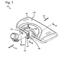
- Fig. 1 is a perspective view of the cleaning device 10th Fig. 2 is an illustration of the cleaning device 10 along the line AA Fig. 1 ,
- the cleaning device 10 has a surface cleaning element 11, which is designed as a wet cleaning nozzle for a vacuum cleaner, so as a vacuum cleaner nozzle for receiving dirt particles.
- the surface cleaning element 11 can be used for wet and dry cleaning of surfaces, eg of floor surfaces.
- a suction channel 17 is formed in each case, can be sucked through the loose dirt.
- a wiping surface is arranged, on which there is a wiper element 19 designed as a wipe.
- the wiping element 19 of the adhering to the surface to be cleaned dirt can be solved by the surface.
- the wiping element 19 is moistened with a cleaning fluid, for example water.
- the cleaning fluid is stored in a liquid container 15 disposed on the surface cleaning member 11, and can be transported to the wiping member 19 through a hose 13.
- the tube 13 first leads from the liquid container 15 to a valve 53 arranged on the surface cleaning element 11 in order to control the flow of the cleaning fluid through the tube.
- the hose 13 leads from the valve 53 to a pump 55 arranged on the surface cleaning element 11, through which the cleaning fluid can be promoted.
- the pump 55 is thus connected downstream of the valve 53 in the transport direction of the cleaning fluid.
- valve 53 of the pump 55 is connected downstream in the transport direction of the cleaning fluid.
- hose 13 carries the cleaning fluid from the valve 53 to the wiper element 19. The operations of the pump 55 and the valve 53 will be discussed in a paragraph below.
- the cleaning device 10 has a guide element 30, which comprises a connecting piece 31 and a suction tube with a handle.
- the connecting piece 31 and the suction pipe are connected to the suction channels 17.
- the connection piece 31 of the guide element 30 is shown in the figures.
- the user grasps the handle of the suction tube and thus the guide element 30.
- the user performs movements to move the surface cleaning element 11 in its main movement directions, namely in a forward direction 71 and to move a backward direction 73 over the surface to be cleaned.
- rollers 21 are arranged, which facilitate a movement in the forward direction 71 and backward direction 73, and whose axes are perpendicular to these two main directions of movement 71, 73.
- the guide element 30 is movably connected to the surface cleaning element 11 via a first 32, a second 33 and a third joint 37.
- the first 32 and second joint 33 which form a double joint 35, are designed as tilting joints arranged in succession with parallel joint axes.
- the axes of the first 32 and second joint 33 run during normal operation of the cleaning device 10, the example in Fig. 1 is shown, parallel to the surface to be cleaned and perpendicular to the main movement directions 71, 73.
- the third joint 37 is designed as a pivot joint, so that a rotatable connection stub 31 is formed.
- the third hinge 37 allows rotation of the guide member 30 with respect to the double hinge 35, allowing the user to more conveniently clean the floor under a bed, for example.
- the guide member 30 is movably connected via the third joint 37 with a second connecting element 43.
- the second connecting element 43 is connected via the second hinge 33 with a first connecting element 41 and this connected via the first joint 32 to the surface cleaning element 11 movable.
- the first joint 32 is arranged on the surface cleaning element 11 and the.
- FIG. 3 and 4 are a sectional view of the cleaning device 10 along the line BB Fig. 1 , Between the first connecting element 41 and the surface cleaning device 11, an elastic element 45 is arranged, through which the first connecting element 41 can be brought into a rest position with respect to the surface cleaning element 11.
- This rest position of the first connecting element 41 is in Fig. 3 shown.
- Fig. 4 a position deviating from the rest position is shown, in which the elastic element 45 exerts a restoring force on the first connecting element 41 in order to bring the first connecting element 41 into the rest position. If this restoring force does not counteract any greater force, the first connecting element 41 is brought into the rest position by the elastic element 45.
- the rest position is taken, for example, when the user turns off the cleaning device after use.
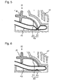
- FIGS. 5 and 6 the detail C turns off Fig. 2 shown.
- the valve 53 is shown, which is formed by a lever 51 and the hose 13.
- the valve 53 and the lever 51 are combined in a work implement 50 of the cleaning apparatus 10 so that the work implement 50 includes the lever 51 and the valve 53.
- This valve 53 is closed by the lever 51, the hose 13 as in Fig. 5 shown disconnected.
- the valve 53 is opened when the lever 51 the Hose 13 as in Fig. 6 shown free, so do not disconnect.
- Such a valve 53 is also referred to as a pinch valve.
- the lever 51 is arranged on a bearing journal 39 of the first connecting element 41, which lies in the articulation axis of the first articulation 32.
- FIGS. 7 and 8 show the pump 55, through which the cleaning fluid can be promoted.
- the pump 55 is part of the Häverrichters 50, so that the Schwarzter 50 also includes the pump 55.
- the pump 55 is not located, like the valve 53, in the right-hand part of the surface-cleaning element 11 viewed in the forward direction 71, but in the left-hand part of the surface-cleaning element 11 viewed in the forward direction 71.
- FIGS. 7 and 8 So do not show detail C.
- Fig. 2 that look like Fig. 1 can be seen on the right side, but show a detail corresponding to the detail C, which is located on the left side of the surface cleaning element 11.
- the pump 55 is actuated by a lever 51 which is arranged on a bearing journal 39 of the first connecting element 41.
- This bearing pin 39 is also located in the hinge axis of the first joint 31.
- the first connecting element 41 thus has a right and left bearing pin 39, on each of which a right and left lever 51 is arranged.
- the pump 55 is actuated by the lever 51, so that a work can be done by the Härichter 50. This work is performed due to a movement of the first articulation 32, so that upon a relative movement of the surface cleaning member 11 and the guide member 30 to each other the Häverrichter 50 can perform a work for actuating the pump 55.
- the cleaning fluid may flow from the hose 13 into a main pumping chamber 57.
- the volume of the main pumping chamber 57 becomes as in FIG Fig. 7 is reduced, so that the cleaning fluid accumulated in the main pumping chamber 57 is transported to the wiping member 19.
- the cleaning device 10 has two additional functions, namely, the pumping of the cleaning fluid by the pump 55 and the control of the flow of the cleaning fluid through the valve 53.
- no additional energy storage such as a spring is needed because the relative movement of guide member 30 and surface cleaning member 11 is used to each other to perform a work for actuating the valve 53 and the pump 55.
- the present invention makes it possible, with simple, constructive and cost-effective means, to provide an improved cleaning device which allows easy cleaning due to the movable connection between the guide element and allow the surface cleaning element.
- a cleaning device can be provided by the invention, which can use a movement during a cleaning process to allow an additional function.
Abstract
Description
Die vorliegende Erfindung betrifft ein Reinigungsgerät mit einem Flächenreinigungselement und einem mit dem Flächenreinigungselement bewegbar verbundenen Führungselement.The present invention relates to a cleaning device having a surface cleaning element and a guide element movably connected to the surface cleaning element.
Beispielsweise ist aus der internationalen Offenlegungsschrift
Weiter offenbart die US-Patentschrift
Schließlich ist aus der deutschen Offenlegungsschrift
Der Erfindung liegt die Aufgabe zugrunde, ein gegenüber dem Stand der Technik verbessertes Reinigungsgerät bereitzustellen. Insbesondere soll ein Reinigungsgerät bereitgestellt werden können, das eine bequeme Reinigung ermöglichen kann. Weiter soll das Reinigungsgerät mit einer Zusatzfunktion ausgestattet sein können, die ohne zusätzliche Energiequelle betrieben werden kann.The invention has for its object to provide a comparison with the prior art improved cleaning device. In particular, a cleaning device should be able to be provided which can facilitate a convenient cleaning. Next, the cleaning device should be equipped with an additional function that can be operated without additional power source.
Die Bezugszeichen in sämtlichen Ansprüchen haben keine einschränkende Wirkung, sondern sollen lediglich deren Lesbarkeit verbessern.The reference numbers in all claims have no limiting effect, but are only intended to improve their readability.
Die Lösung der gestellten Aufgabe gelingt durch ein Reinigungsgerät mit den Merkmalen des Anspruchs 1.The solution of the problem is achieved by a cleaning device having the features of claim 1.
Durch das Flächenreinigungselement des Reinigungsgeräts können Flächen wie z.B. Bodenflächen, Fensterbänke, Fensterflächen, Glasflächen, Regalböden sowie Problemflächen wie PC-Tastaturen oder Bilderrahmen gereinigt werden. Solche Flächen können horizontal oder vertikal verlaufen. Das Führungselement ist der Teil des Reinigungsgeräts, der dazu vorgesehen ist, das Flächenreinigungselement im bestimmungsgemäßen Betrieb des Reinigungsgeräts über die zu reinigenden Flächen zu führen. Hierzu kann der Benutzer das Führungselement mit der Hand ergreifen, um das Flächenreinigungselement während eines Reinigungsvorgangs über eine Fläche zu bewegen.By the surface cleaning element of the cleaning device surfaces such. Floor surfaces, window sills, windows, glass surfaces, shelves and problem areas such as PC keyboards or picture frames are cleaned. Such surfaces can be horizontal or vertical. The guide element is the part of the cleaning device which is intended to guide the surface cleaning element in the intended operation of the cleaning device over the surfaces to be cleaned. For this purpose, the user can take the guide element by hand to move the surface cleaning element during a cleaning process over a surface.
Reinigungsgeräte zur Flächenreinigung sind häufig mit einer bewegbaren Verbindung zwischen dem Führungselement und dem Flächenreinigungselement ausgestattet, um eine bequemere Handhabung des Reinigungsgeräts zu ermöglichen. Denn durch die bewegbare Verbindung können die Bewegungen des Benutzers, der das Führungselement in seiner Hand hält, während des Reinigungsvorgangs besser ausgeglichen werden. Weiter wird durch die bewegbare Verbindung bessere Reinigungsergebnisse erzielbar, weil das Flächenreinigungselement unabhängig von der Lage des Führungselements optimal auf der zu reinigenden Fläche aufliegen kann.Cleaning machines for surface cleaning are often equipped with a movable connection between the guide element and the surface cleaning element in order to facilitate a more convenient handling of the cleaning device. Because of the movable connection, the movements of the user who holds the guide element in his hand, during the cleaning process better be compensated. Furthermore, better cleaning results can be achieved by the movable connection because the surface cleaning element can rest optimally on the surface to be cleaned, regardless of the position of the guide element.
Die Erfindung nutzt die Relativbewegung zwischen Führungselement und Flächenreinigungselement während eines Reinigungsvorgangs aus, um aufgrund dieser Relativbewegung Arbeit zu verrichten. Mit anderen Worten, durch die Erfindung werden Bewegungen, die ohnehin während eines Reinigungsvorgangs ausgeführt werden, zum Verrichten von Arbeit nutzbar gemacht. Vorteilhafterweise kann die aufgrund der Relativbewegung von dem Arbeitsverrichter verrichtete Arbeit zum Betreiben einer Zusatzfunktion des Reinigungsgeräts genutzt werden, ohne eine zusätzliche Energiequelle bereitstellen zu müssen. Eine Zusatzfunktion kann z.B. darin bestehen, ein Element des Reinigungsgeräts zu betätigen oder Energie in einem Energiespeicher zu speichern, um diese zu einem späteren Zeitpunkt nutzen zu können. Durch die Zusatzfunktion kann die Hauptfunktion des Reinigungsgeräts, nämlich die Reinigung einer Fläche, verbessert oder erleichtert werden.The invention makes use of the relative movement between guide element and surface cleaning element during a cleaning process in order to perform work due to this relative movement. In other words, by the invention, movements which are carried out anyway during a cleaning operation are utilized for performing work. Advantageously, the work performed by the work handler due to the relative movement can be used for operating an additional function of the cleaning device without having to provide an additional energy source. An additional function may e.g. consist in operating an element of the cleaning device or to store energy in an energy storage in order to use it at a later time can. By the additional function, the main function of the cleaning device, namely the cleaning of a surface can be improved or facilitated.
Vorteilhafte Aus- und Weiterbildungen, welche einzeln oder in Kombination miteinander eingesetzt werden können, sind Gegenstand der abhängigen Ansprüche.Advantageous embodiments and developments, which can be used individually or in combination with each other, are the subject of the dependent claims.
In einer bevorzugten Ausführung der Erfindung ist das Führungselement über zumindest ein erstes Gelenk mit dem Flächenreinigungselement bewegbar verbunden. Besonders vorzugsweise ist das erste Gelenk an dem Flächenreinigungselement angeordnet. Durch das erste Gelenk können die Freiheitsgrade der Relativbewegung zwischen dem Führungselement und dem Flächenreinigungselement festgelegt werden. Dies kann die Handhabung des Flächenreinigungselements vereinfachen und/oder eine einfache Konstruktion des Arbeitsverrichters ermöglichen. Das erste Gelenk kann z.B. als Kugelgelenk, Kippgelenk, Schwenkgelenk oder Pendelgelenk ausgeführt sein. Zwischen dem Führungselement und dem Flächenreinigungselement können gemäß der vorliegenden Erfindung Verbindungselemente angeordnet sein. Hierdurch kann eine für den Benutzer bequeme Handhabung erreicht werden, weil er sich z.B. während eines Reinigungsvorgangs weniger bücken muss.In a preferred embodiment of the invention, the guide element is movably connected to the surface cleaning element via at least one first joint. Particularly preferably, the first joint is arranged on the surface cleaning element. By the first joint, the degrees of freedom of the relative movement between the guide element and the surface cleaning element can be determined. This may simplify the handling of the surface cleaning element and / or allow a simple construction of the work implement. The first joint can be designed, for example, as a ball joint, tilting joint, swivel joint or pendulum joint. Between the guide element and the surface cleaning element connecting elements can be arranged according to the present invention. As a result, a convenient for the user handling can be achieved, for example, he must bend down less during a cleaning process.
In einer weiteren bevorzugten Ausführungsform ist das Führungselement zusätzlich über ein zweites Gelenk mit dem Flächenreinigungselement bewegbar verbunden. Besonders vorzugsweise ist das Führungselement zuerst über das zweite und anschließend über das erste Gelenk mit dem Flächenreinigungselement bewegbar verbunden. In dieser Ausführungsform der Erfindung sind das erste und das zweite Gelenk hintereinander angeordnet und bilden dadurch ein Doppelgelenk. Das zweite Gelenk kann genauso wie das erste Gelenk z.B. als Kugelgelenk, Kippgelenk, Schwenkgelenk oder Pendelgelenk ausgeführt sein. Erfindungsgemäß bevorzugt ist ein erstes Verbindungselement zwischen dem ersten und dem zweiten Gelenk, und damit zwischen dem Führungselement und dem Flächenreinigungselement angeordnet. Hierzu kann das Führungselement über das zweite Gelenk mit dem ersten Verbindungselement und das erste Verbindungselement über das erste Gelenk mit dem Flächenreinigungselement verbunden sein. Natürlich können zwischen dem ersten Führungselement und dem Flächenreinigungselement noch weitere Verbindungselemente angeordnet sein. Vorteilhafterweise ist durch das erste und zweite Gelenk, also durch das Doppelgelenk, erreichbar, dass eine Vorwärts- und Rückwärtsbewegung des Benutzers während des Reinigungsvorgangs besser ausgeglichen werden kann, so dass das Flächenreinigungselement von dem Führungselement effektiver über die zu reinigende Fläche geführt werden kann. Dies kann die Reinigungsergebnisse verbessern, weil das Flächenreinigungselement besser mit der zu reinigenden Fläche in Kontakt bleibt. Insbesondere kann ein Verkippen des Flächenreinigungselements relativ zu der zu reinigenden Fläche vorteilhafterweise vermieden werden. Außerdem kann eine für den Benutzer bequemere Handhabung erreicht werden, da der Benutzer z.B. die Vor- und Rückwärtsbewegungen während des Reinigungsvorganges nicht mehr so stark durch Auf- und Ab-Bewegungen ausgleichen muss.In a further preferred embodiment, the guide element is additionally movably connected to the surface cleaning element via a second joint. Particularly preferably, the guide element is first movably connected to the surface cleaning element via the second and then via the first joint. In this embodiment of the invention, the first and the second joint are arranged one behind the other and thereby form a double joint. The second joint may be the same as the first joint e.g. be designed as a ball joint, tilting joint, swivel joint or pendulum joint. According to the invention, a first connecting element is preferably arranged between the first and the second joint, and thus between the guide element and the surface cleaning element. For this purpose, the guide element can be connected via the second joint to the first connecting element and the first connecting element via the first joint with the surface cleaning element. Of course, further connecting elements can be arranged between the first guide element and the surface cleaning element. Advantageously, can be achieved by the first and second joint, so by the double joint, that a forward and backward movement of the user during the cleaning process can be better compensated, so that the surface cleaning element can be performed by the guide element more effectively over the surface to be cleaned. This can improve the cleaning results because the surface cleaning element remains in better contact with the surface to be cleaned. In particular, a tilting of the surface cleaning element relative to the surface to be cleaned can be advantageously avoided. In addition, a more convenient handling for the user can be achieved since the user can e.g. the forward and backward movements during the cleaning process no longer have to compensate so much by up and down movements.
In einer bevorzugten Ausführung der Erfindung sind das erste und zweite Gelenk als Kippgelenk ausgeführt, deren Gelenkachsen besonders vorzugsweise parallel zueinander verlaufen. Mit Vorteil verlaufen die Achsen des als Doppelgelenk ausgeführten ersten und zweiten Gelenks bei bestimmungsgemäßem Betrieb des Reinigungsgeräts parallel zu der zu reinigenden Fläche und senkrecht zur Hauptbewegungsrichtung. Eine solche Anordnung kann die Handhabung des Reinigungsgeräts vereinfachen, da bei einer Bewegung des Reinigungsgeräts in Hauptbewegungsrichtung eine von der Hauptbewegungsrichtung abweichende und damit ungewünschte Bewegung des Flächenreinigungselements verhindert werden kann. So kann z.B. verhindert werden, dass das Flächenreinigungselement verkantet oder sich verdreht, wenn es von dem Benutzer über das Führungselement in eine Hauptbewegungsrichtung bewegt wird.In a preferred embodiment of the invention, the first and second joint are designed as tilting joint, the joint axes of which are particularly preferably parallel to each other. Advantageously, the axes of the executed as a double joint first and second joint during normal operation of the cleaning device parallel to the surface to be cleaned and perpendicular to the main movement direction. Such an arrangement can simplify the handling of the cleaning device, since during movement of the cleaning device in the main direction of movement one of the Main movement direction deviating and thus unwanted movement of the surface cleaning element can be prevented. For example, it can be prevented that the surface cleaning element tilted or twisted when it is moved by the user on the guide member in a main movement direction.
In einer bevorzugten Ausführung der Erfindung ist das Führungselement über ein drittes Gelenk mit dem Flächenreinigungselement verbunden, besonders vorzugsweise ist das Führungselement über das dritte Gelenk mit einem zweiten Verbindungselement und das zweite Verbindungselement über das zweite Gelenk mit dem ersten Verbindungselement verbunden. Das dritte Gelenk ist vorzugsweise als Drehgelenk ausgebildet, so dass der Benutzer das Führungselement bezüglich des Flächenreinigungselements drehen und dadurch eine Fläche bequemer reinigen kann. Natürlich kann das Führungselement erfindungsgemäß auch über weitere Gelenke mit dem Flächenreinigungselement verbunden sein, wobei zwischen dem Führungselement und dem Flächenreinigungselement entsprechend Verbindungselemente angeordnet sein können. So kann das Führungselement z.B. über ein viertes, fünftes oder sechstes Gelenk mit dem Flächenreinigungselement verbunden sein. Entsprechend kann ein drittes, viertes oder fünftes Verbindungselement zwischen dem Führungselement und dem Flächenreinigungselement angeordnet sein. Beispielsweise kann das Führungselement über eine Gliederkette, die durch ineinander greifende Kugelgelenke gebildet sein kann, mit dem Flächenreinigungselement verbunden sein.In a preferred embodiment of the invention, the guide element is connected via a third joint with the surface cleaning element, particularly preferably the guide element is connected via the third joint with a second connecting element and the second connecting element via the second joint with the first connecting element. The third joint is preferably formed as a hinge, so that the user can rotate the guide element with respect to the surface cleaning element and thereby easier to clean a surface. Of course, the guide element according to the invention can also be connected via further joints with the surface cleaning element, wherein between the guide element and the surface cleaning element according to connecting elements can be arranged. Thus, the guide element may e.g. be connected via a fourth, fifth or sixth joint with the surface cleaning element. Accordingly, a third, fourth or fifth connecting element between the guide element and the surface cleaning element can be arranged. For example, the guide element via a link chain, which may be formed by interlocking ball joints, be connected to the surface cleaning element.
Die Erfindung weiterbildend ist vorzugsweise vorgesehen, dass der Arbeitsverrichter aufgrund einer Bewegung des ersten und/oder zweiten Gelenks eine Arbeit verrichten kann. Dazu kann der Arbeitsverrichter z.B. mit einem Achselement des ersten und/oder zweiten Gelenks verbunden sein. Vorteilhafterweise wird bei einer Relativbewegung des Flächenreinigungselements und des Führungselements zueinander das erste und/oder das zweite Gelenk bewegt, so dass der Arbeitsverrichter aufgrund der Gelenkbewegung eine Arbeit verrichten kann. In einer besonders bevorzugten Ausführung kann der Arbeitsverrichter aufgrund einer Bewegung des ersten Gelenks, wobei das erste Gelenk vorzugsweise an dem Flächenreinigungselement angeordnet ist, eine Arbeit verrichten. Das zweite Gelenk ist hierbei zwischen dem ersten Gelenk und dem Führungselement angeordnet. In dieser Ausführung ist das Führungselement also zuerst über das zweite Gelenk und anschließend über das erste Gelenk mit dem Flächenreinigungselement bewegbar verbunden. Vorteilhafterweise kann hierdurch die Bewegung, die zur Flächenreinigung notwendig ist und die von dem Benutzer während des Reinigungsvorgangs durchgeführt wird, besonders effektiv zur Verrichtung der Arbeit durch den Arbeitsverrichter umgesetzt werden, weil diese Bewegung zu einer maximalen Winkelbewegung des ersten Gelenks führen kann.The invention further development is preferably provided that the Arbeitsverrichter can do a job due to movement of the first and / or second joint. For this purpose, the work harvester can be connected, for example, to an axle element of the first and / or second joint. Advantageously, in a relative movement of the surface cleaning element and the guide element to each other, the first and / or the second joint is moved, so that the Arbeitsverrichter can do a job due to the joint movement. In a particularly preferred embodiment, the work implement can perform a work due to a movement of the first joint, wherein the first joint is preferably arranged on the surface cleaning element. The second joint is in this case arranged between the first joint and the guide element. In this embodiment, the guide element is therefore first on the second joint and then on the first joint with the surface cleaning element movably connected. Advantageously, thereby, the movement necessary for surface cleaning, which is performed by the user during the cleaning operation, can be implemented particularly effectively for the work to be performed by the work maker, because this movement can lead to a maximum angular movement of the first joint.
Erfindungsgemäß ist vorzugsweise vorgesehen, dass zumindest eine Achse des ersten und/oder zweiten Gelenks, durch das oder durch die die Relativbewegung ermöglicht wird, aufgrund derer der Arbeitsverrichter eine Arbeit verrichten kann, bei bestimmungsgemäßem Betrieb des Reinigungsgeräts parallel zu der zu reinigenden Fläche und/oder senkrecht zu einer Hauptbewegungsrichtung verläuft. Durch diese Anordnung kann vorteilhafterweise die Arbeit, die der Arbeitsverrichter während eines Reinigungsvorgangs verrichten kann, weiter erhöht werden, da eine Bewegung in Hauptbewegungsrichtung während des Reinigungsvorgangs am häufigsten auftritt.According to the invention, it is preferably provided that at least one axis of the first and / or second articulation, by or through which the relative movement is made possible, on the basis of which the Arbeitsverrichter can do a job, in normal operation of the cleaning device parallel to the surface to be cleaned and / or perpendicular to a main movement direction. By this arrangement, the work which the work maker can perform during a cleaning operation can be advantageously increased further, since a movement in the main movement direction during the cleaning process occurs most frequently.
In einer bevorzugten Ausführung der Erfindung weist der Arbeitsverrichter ein Getriebe auf. Ein Getriebe ist ein Element, durch das eine Bewegung in eine andere Bewegung umgewandelt werden kann. So kann z. B. eine Bewegung mit hoher Rotationsgeschwindigkeit in eine Bewegung mit niedriger Rotationsgeschwindigkeit oder eine Rotationsbewegung in eine Translationsbewegung umgewandelt werden. Vorteilhafterweise kann die durch den Arbeitsverrichter verrichtete Arbeit aufgrund des Getriebes besser genutzt werden, da das Getriebe eine Bewegung zwischen Führungselement und Flächenreinigungselement in eine nutzbare Bewegung umwandeln kann. So kann es z. B. die Rotationsbewegung eines Gelenks in eine Bewegung mit translatorischer Komponente umwandeln. Das Getriebe kann z.B. als Hebel ausgeführt sein, der an einem Achselement des ersten oder zweiten Gelenks angebracht ist und der eine Drehbewegung des Achselements in eine Bewegung mit einer translatorischen Komponente umwandeln kann. Hierdurch kann die Drehbewegung des Achselements besser zur Verrichtung von Arbeit genutzt werden. Das Getriebe des Arbeitsverrichters kann erfindungsgemäß mit dem Führungselement, einem Verbindungselement und/oder dem Flächenreinigungselement verbunden sein, um die Relativbewegung des Führungselements und des Flächenreinigungselements zueinander zur Verrichtung von Arbeit nutzen zu können.In a preferred embodiment of the invention, the work harvester on a transmission. A gear is an element by which a movement can be converted into another movement. So z. For example, a high-speed rotation movement can be converted into a low-speed rotation movement or a rotational movement can be translated. Advantageously, the work performed by the work implement can be better utilized due to the transmission, since the transmission can convert movement between the guide element and the surface cleaning element into a usable movement. So it may be z. B. convert the rotational movement of a joint in a movement with translational component. The transmission may, for example, be designed as a lever which is attached to an axle element of the first or second articulation and which can convert a rotational movement of the axle element into a movement with a translational component. As a result, the rotational movement of the shaft member can be better used for the performance of work. According to the invention, the transmission of the work chopper can be connected to the guide element, a connecting element and / or the surface cleaning element in order to be able to use the relative movement of the guide element and the surface cleaning element to one another for the purpose of performing work.
Die Erfindung weiterbildend ist vorzugsweise vorgesehen, dass das Flächenreinigungselement als Staubsaugerdüse zur Aufnahme von Schmutzpartikeln ausgebildet ist. Eine Staubsaugerdüse ist üblicherweise über einen Saugluftkanal mit einem Staubsauger verbunden, um Schmutzpartikel von einer Fläche aufnehmen und einem Staubsammelbehältnis zuführen zu können. Die Staubsaugerdüse kann hierzu einen Luftkanal aufweisen, durch den Schmutzpartikel während der Reinigung hindurchströmen können. Bei einem als Staubsaugerdüse ausgebildeten Flächenreinigungselement ist das Führungselement besonders vorzugsweise als Saugluftkanal, z.B. als drehbarer Verbindungsstutzen ausgebildet. Das Führungselement kann sich auch aus einem drehbaren Verbindungsstutzen und einem mit dem Verbindungsstutzen verbundenen Saugrohr zusammensetzen. Üblicherweise ist an einem Saugrohr ein durchströmbarer Handgriff angeordnet, den der Benutzer ergreifen kann. Eine Staubsaugerdüse kann zur Feucht- und/oder Trockenreinigung von Flächen genutzt werden.The invention further development is preferably provided that the surface cleaning element is designed as a vacuum cleaner nozzle for receiving dirt particles. A vacuum cleaner nozzle is usually connected via a suction air duct with a vacuum cleaner to receive dirt particles from a surface and to be able to lead a dust collection container. For this purpose, the vacuum cleaner nozzle can have an air channel through which dirt particles can flow during cleaning. In a surface cleaning element designed as a vacuum cleaner nozzle, the guide element is particularly preferably as Saugluftkanal, e.g. designed as a rotatable connection piece. The guide member may also be composed of a rotatable connection piece and a suction pipe connected to the connecting piece. Usually, a flow-through handle is arranged on a suction tube, which the user can take. A vacuum cleaner nozzle can be used for wet and / or dry cleaning of surfaces.
In einer Ausführung der Erfindung ist das Flächenreinigungselement als Feuchtreinigungsdüse für einen Staubsauger ausgebildet. Durch eine Feuchtreinigungsdüse kann ein Wischen und Saugen in einem Arbeitsgang erfolgen, so dass Hartböden effektiver gereinigt und dadurch die Reinigungsergebnisse verbessert werden können. Durch die Feuchtigkeit der Feuchtreinigungsdüse können z.B. Schmutzpartikel gelöst werden, die an der zu reinigenden Fläche anhaften. Bei einer typischen Feuchtreinigungsdüse ist eine Wischfläche zwischen zwei Saugkanälen positioniert, wobei durch die Saugkanäle loser Schmutz aufgesaugt und durch die Wischfläche der am Boden fest anhaftende Schmutz abgelöst werden kann. Hierzu kann an der Wischfläche ein Wischelement, z.B. ein Wischtuch angeordnet sein, das mit einem Reinigungsfluid befeuchtet wird. Dieses Reinigungsfluid kann z.B. Wasser oder eine Reinigungslösung sein. Üblicherweise wird das Reinigungsfluid in einem Flüssigkeitsbehälter, der z.B. an dem Flächenreinigungselement angebracht ist, bevorratet.In one embodiment of the invention, the surface cleaning element is designed as a wet cleaning nozzle for a vacuum cleaner. Through a wet cleaning nozzle, a wipe and vacuum can be done in one operation, so that hard floors can be cleaned more effectively and thus the cleaning results can be improved. Due to the humidity of the wet cleaning nozzle, e.g. Dirt particles are released, which adhere to the surface to be cleaned. In a typical wet cleaning nozzle, a wiping surface is positioned between two suction channels, wherein sucked through the suction channels loose dirt and can be replaced by the wiping surface of the soil firmly adhering dirt. For this purpose, a wiping element, e.g. a wipe may be arranged which is moistened with a cleaning fluid. This cleaning fluid may e.g. Water or a cleaning solution. Usually, the cleaning fluid is stored in a liquid container, e.g. is attached to the surface cleaning element, stored.
Erfindungsgemäß ist vorzugsweise vorgesehen, dass der Arbeitsverrichter ein Ventil umfasst und aufgrund der Relativbewegung des Reinigungselements und des Führungselements zueinander eine Arbeit zum Betätigen des Ventils verrichtbar ist. Vorteilhafterweise kann durch die Betätigung des Ventils ein Fluidfluss, z.B. in einer Feuchtreinigungsdüse, kontrolliert werden, so dass der Benutzer das Ventil nicht manuell betätigen muss und dadurch die Bedienung des Reinigungsgeräts vereinfacht werden kann. Die zum Betätigen des Ventils verrichtete Arbeit kann z.B. ein Öffnen und Schließen des Ventils bewirken. In einer besonders bevorzugten Ausführung ist das Ventil als Quetschventil ausgebildet, wobei das Schließen und Öffnen des Ventils dadurch erfolgt, dass ein Schlauchabschnitt über einen Hebel abgedrückt und wieder freigegeben wird.According to the invention, it is preferably provided that the work harvester comprises a valve and due to the relative movement of the cleaning element and the guide element to each other a work for actuating the valve can be accomplished. Advantageously, by the actuation of the valve, a fluid flow, for example in a Humid cleaning nozzle, so that the user does not have to manually operate the valve, thereby simplifying the operation of the cleaning device. The work done to actuate the valve may, for example, cause the valve to open and close. In a particularly preferred embodiment, the valve is designed as a pinch valve, wherein the closing and opening of the valve takes place in that a hose section is pressed off via a lever and released again.
Die Erfindung weiterbildend ist vorzugsweise vorgesehen, dass der Arbeitsverrichter eine Pumpe umfasst und aufgrund der Relativbewegung des Flächenreinigungselements und des Führungselements zueinander eine Arbeit zum Betätigen der Pumpe verrichtbar ist. Vorteilhafterweise kann durch die Relativbewegung die Pumpe betätigt werden, um ein Reinigungsfluid z.B. aus einem Flüssigkeitsbehälter zu fördern und dieses zur Reinigung einer Fläche zu nutzen. Das Reinigungsfluid kann hierzu z.B. auf die zu reinigende Fläche gesprüht werden oder zum Befeuchten eines Wischelements genutzt werden. Um eine einfache und effektive Betätigung der Pumpe zu ermöglichen, weist der Arbeitsverrichter vorzugsweise einen Hebel auf, der an einem Achselement des ersten oder zweiten Gelenks angebracht sein kann. Bei einer besonders bevorzugten Ausführung des Reinigungsgeräts umfasst der Arbeitsverrichter die Pumpe und das Ventil. In dieser Ausführung kann das Ventil der Pumpe in Transportrichtung des Reinigungsfluids vor-oder nachgeschaltet sein. Die Transportrichtung ist die Richtung, in die das Reinigungsfluid durch die Pumpe z.B. von dem Flüssigkeitsbehälter zu dem Wischelement gefördert wird.The invention further development is preferably provided that the Arbeitsrichter comprises a pump and due to the relative movement of the surface cleaning element and the guide element to each other a work for actuating the pump is verrichtbar. Advantageously, by the relative movement, the pump can be actuated to provide a cleaning fluid e.g. from a liquid container to promote and use this to clean a surface. The cleaning fluid may for this purpose be e.g. be sprayed on the surface to be cleaned or used to moisten a wiper element. In order to enable a simple and effective actuation of the pump, the work harvester preferably has a lever which can be attached to an axle element of the first or second articulation. In a particularly preferred embodiment of the cleaning device, the working implement comprises the pump and the valve. In this embodiment, the valve of the pump in the transport direction of the cleaning fluid upstream or downstream. The direction of transport is the direction in which the cleaning fluid is pumped by the pump, e.g. is conveyed from the liquid container to the wiper element.
Die Erfindung umfasst weiter Ausführungsformen, in denen der Arbeitsverrichter einen Generator zur Erzeugung elektrischer Energie und/oder ein Zählwerk umfasst. Durch die erzeugte elektrische Energie kann z.B. eine Beleuchtung betrieben werden. Das Zählwerk kann z.B. genutzt werden, um eine Zustandsanzeige zu betreiben oder einen nötigen Wechsel eines Betriebsmittels anzuzeigen.The invention further includes embodiments in which the work implement comprises a generator for generating electrical energy and / or a counter. By the generated electrical energy, e.g. be operated a lighting. The counter may e.g. be used to operate a status display or display a necessary change of a resource.
In einer bevorzugten Ausführungsform weist das Reinigungsgerät ein elastisches Element auf, durch das der Arbeitsverrichter in eine Ruhestellung bringbar ist. Dies kann die Bedienung des Reinigungsgeräts vereinfachen, da der Benutzer beispielsweise nach oder während eines Reinigungsvorgangs nicht auf die Stellung des Arbeitsverrichters achten muss. Besonders vorzugsweise ist das elastische Element mit dem Führungselement, zumindest einem der Verbindungselemente und/oder dem Flächenreinigungselement in Wirkverbindung, um den Arbeitsverrichter dadurch in die Ruhestellung zu bringen. Eine Wirkverbindung kann ein Berühren oder eine feste Verbindung umfassen. Vorzugsweise ist das elastische Element zwischen dem Flächenreinigungselement und dem Führungselement oder zwischen dem Flächenreinigungselement und dem ersten Verbindungselement angeordnet. Um den Arbeitsverrichter in die Ruhestellung zu bringen, kann das elastische Element eine Rückstellkraft auf den Arbeitsverrichter ausüben, durch die der Arbeitsverrichter dann in eine Ruhestellung bringbar ist, wenn dieser Rückstellkraft keine größeren Kräfte entgegenwirken. Beispielweise können solche Kräfte durch die Bewegungen entstehen, die der Benutzer während eines Reinigungsvorgangs durchführt. Der Benutzer kann aber auch Bewegungen durchführen, bei denen Kräfte entstehen, die mit der Rückstellkraft gleichgerichtet sind. Mit anderen Worten: eine Bewegung des Benutzers kann vorteilhafterweise auch durch das elastische Element unterstützt werden. Vorzugsweise ist das elastische Element als Feder, z.B. als Zug- oder Druckfeder ausgeführt.In a preferred embodiment, the cleaning device has an elastic element, by means of which the work harvester can be brought into a rest position. This can simplify the operation of the cleaning device, since the user, for example, after or during a cleaning process does not have to pay attention to the position of the Arbeitsverrichters. Particularly preferably, the elastic element with the guide element, at least one of the connecting elements and / or the surface cleaning element in operative connection to thereby bring the Arbeitsverrichter in the rest position. An active compound may comprise a contact or a solid compound. Preferably, the elastic element is arranged between the surface cleaning element and the guide element or between the surface cleaning element and the first connecting element. In order to bring the work harvester in the rest position, the elastic element can exert a restoring force on the Arbeitsrerichter, by which the Arbeitsverrichter is then brought into a rest position, if this restoring force counteracts no major forces. For example, such forces may arise from the movements that the user makes during a cleaning operation. The user can also perform movements in which forces arise, which are rectified with the restoring force. In other words, a movement of the user can advantageously also be supported by the elastic element. Preferably, the elastic element is designed as a spring, for example as a tension or compression spring.
In einer besonders bevorzugten Ausführung der Erfindung, in der der Arbeitsverrichter das Ventil umfasst und durch das elastische Element in eine Ruhestellung bringbar ist, ist das Ventil in Ruhestellung verschlossen. Hierdurch kann vorteilhafterweise verhindert werden, dass Flüssigkeit ausläuft, was eine sichere Aufbewahrung des Reinigungsgeräts ermöglichen kann. Umfasst der Arbeitsverrichter eine Pumpe und ist durch das elastische Element in eine Ruhestellung bringbar, kann vorteilhafterweise die Pumpwirkung der Pumpe verbessert werden. Denn dadurch, dass der Arbeitsverrichter durch das elastische Element in eine Ruhestellung bringbar ist, muss der Benutzer nur noch eine Bewegung in eine Richtung durchführen, da die Bewegung in die andere Richtung durch das elastische Element sichergestellt werden kann. So kann z.B. der Benutzer bei einer Vorwärtsbewegung die Rückstellkraft des elastischen Elements überwinden und dadurch die Pumpe betätigen und muss bei einer anschließenden Rückwärtsbewegung nur noch das Führungselement zurückziehen. Er muss vorteilhafterweise nicht darauf achten, eine vollständige Bewegung von Führungselement relativ zu Flächenreinigungselement beim Zurückziehen auszuführen, da diese durch das elastische Element sichergestellt werden kann.In a particularly preferred embodiment of the invention, in which the work harvester comprises the valve and can be brought by the elastic element in a rest position, the valve is closed in the rest position. As a result, it can be advantageously prevented that liquid leaks, which may allow a safe storage of the cleaning device. If the laborator comprises a pump and can be brought into a rest position by the elastic element, advantageously the pumping effect of the pump can be improved. For the fact that the laborator can be brought into a rest position by the elastic element, the user only has to perform a movement in one direction, since the movement can be ensured in the other direction by the elastic element. For example, the user can overcome the restoring force of the elastic element during a forward movement and thereby actuate the pump and only has to retract the guide element in a subsequent backward movement. He advantageously need not be careful to perform a complete movement of guide element relative to surface cleaning element during retraction, since it can be ensured by the elastic element.
Die vorliegende Erfindung ermöglicht mit einfachen, konstruktiven und kostengünstigen Mitteln die Bereitstellung eines verbesserten Reinigungsgeräts, das eine bequeme Reinigung aufgrund der bewegbaren Verbindung zwischen dem Führungselement und dem Flächenreinigungselement ermöglichen kann. Insbesondere kann durch die Erfindung ein Reinigungsgerät bereitgestellt werden, das eine Bewegung während eines Reinigungsvorgangs nutzen kann, um eine Zusatzfunktion zu ermöglichen.The present invention makes it possible, with simple, constructive and cost-effective means, to provide an improved cleaning device which can enable convenient cleaning due to the movable connection between the guide element and the surface cleaning element. In particular, a cleaning device can be provided by the invention, which can use a movement during a cleaning process to allow an additional function.
Weitere vorteilhafte Ausgestaltungen werden nachfolgend an Hand eines in den Zeichnungen dargestellten Ausführungsbeispiels, auf welches die Erfindung jedoch nicht beschränkt ist, näher beschrieben.Further advantageous embodiments will be described in more detail below with reference to an embodiment shown in the drawings, to which the invention is not limited.
Es zeigen schematisch:
- Fig. 1
- ein Reinigungsgerät in perspektivischer Darstellung;
- Fig. 2
- das Reinigungsgerät in Schnittdarstellung entlang der Linie A-A aus
Fig. 1 ; - Fig. 3
- das Reinigungsgerät in Schnittdarstellung entlang der Linie B-B aus
Fig. 1 , wobei ein erstes Verbindungselement in einer Ruhestellung ist; - Fig. 4
- das Reinigungsgerät in Schnittdarstellung entlang der Linie B-B aus
Fig. 1 , wobei das erstes Verbindungselement in einer von der Ruhestellung abweichenden Stellung ist; - Fig. 5
- ein Ventil des Reinigungsgeräts nach Detail C aus
Fig. 2 in einer Stellung, in der das erste Verbindungselement in der Ruhestellung ist; - Fig. 6
- das Ventil des Reinigungsgeräts nach Detail C aus
Fig. 2 in einer Stellung, in der das erste Verbindungselement in einer von der Ruhestellung abweichenden Stellung ist; - Fig. 7
- eine Pumpe des Reinigungsgeräts nach einem Detail, das Detail B aus
Fig. 2 entspricht, wobei das das erste Verbindungselement in der Ruhestellung ist;
- Fig. 8
- eine Pumpe des Reinigungsgeräts nach einem Detail, das Detail B aus
Fig. 2 entspricht, wobei das das erste Verbindungselement in einer von der Ruhestellung abweichenden Stellung ist.
- Fig. 1
- a cleaning device in perspective view;
- Fig. 2
- the cleaning device in section along the line AA
Fig. 1 ; - Fig. 3
- the cleaning device in section along the line BB
Fig. 1 wherein a first connecting element is in a rest position; - Fig. 4
- the cleaning device in section along the line BB
Fig. 1 wherein the first connecting element is in a position deviating from the rest position; - Fig. 5
- a valve of the cleaning device to detail C from
Fig. 2 in a position in which the first connecting element is in the rest position; - Fig. 6
- the valve of the cleaning device after detail C off
Fig. 2 in a position in which the first connecting element is in a position deviating from the rest position; - Fig. 7
- a pump of the cleaner after a detail, the detail B off
Fig. 2 corresponds, which is the first connecting element in the rest position;
- Fig. 8
- a pump of the cleaner after a detail, the detail B off
Fig. 2 corresponds, wherein the first connecting element is in a position deviating from the rest position.
Bei der nachfolgenden Beschreibung von einer bevorzugten Ausführungsform der vorliegenden Erfindung bezeichnen gleiche Bezugszeichen gleiche oder vergleichbare Komponenten.In the following description of a preferred embodiment of the present invention, like reference characters designate like or similar components.
Das Reinigungsgerät 10 weist ein Führungselement 30 auf, das einen Verbindungsstutzen 31 und ein Saugrohr mit einem Handgriff umfasst. Der Verbindungsstutzen 31 und das Saugrohr sind mit den Saugkanälen 17 verbunden. Aus Darstellungsgründen ist in den Figuren nur der Verbindungsstutzen 31 des Führungselements 30 gezeigt. Um das Flächenreinigungselement 11 über die zu reinigende Fläche zu führen, ergreift der Benutzer den Handgriff des Saugrohrs und somit das Führungselement 30. Während des Reinigungsvorgangs führt der Benutzer Bewegungen aus, um das Flächenreinigungselement 11 im bestimmungsgemäßen Betrieb in seine Hauptbewegungsrichtungen, nämlich in eine Vorwärtsrichtung 71 und eine Rückwärtsrichtung 73 über die zu reinigende Fläche zu bewegen. An dem Flächenreinigungselement 11 sind Rollen 21 angeordnet, die eine Bewegung in Vorwärtsrichtung 71 und Rückwärtsrichtung 73 erleichtern, und dessen Achsen senkrecht zu diesen beiden Hauptbewegungsrichtungen 71, 73 verlaufen.The
Das Führungselement 30 ist über ein erstes 32, ein zweites 33 und ein drittes Gelenk 37 mit dem Flächenreinigungselement 11 bewegbar verbunden. Das erste 32 und zweite Gelenk 33, die ein Doppelgelenk 35 bilden, sind als hintereinander angeordnete Kippgelenke mit parallelen Gelenkachsen ausgeführt. Die Achsen des ersten 32 und zweiten Gelenks 33 verlaufen bei bestimmungsgemäßem Betrieb des Reinigungsgeräts 10, der z.B. in
In den
Durch die Relativbewegung des ersten Verbindungselements 41 und des Flächenreinigungselements 11 kann also eine Arbeit zum Betätigen des Ventils 53 verrichtet werden, die darin besteht, das Ventil 53 zu öffnen und zu schließen. Diese Arbeit wird aufgrund einer Bewegung des ersten Gelenks 32 verrichtet, da der Hebel 51 an dem Lagerzapfen 39 angeordnet ist, der in der Gelenkachse des ersten Gelenks 32 liegt. Da das erste Verbindungselement 41 mit dem Führungselement 30 verbunden ist, kann der Arbeitsverrichter 50 aufgrund einer Relativbewegung des Flächenreinigungselements 11 und des Führungselements 30 zueinander eine Arbeit zum Betätigen des Ventils 53 verrichten. Diese Relativbewegung wird durch das erste Gelenk 32 ermöglicht, dessen Achse wie bereits erwähnt bei bestimmungsgemäßem Betrieb parallel zu der zu reinigenden Fläche und senkrecht zu den Hauptbewegungsrichtungen 71, 73 verläuft.By the relative movement of the first connecting
Durch das Ventil 53 und die Pumpe 55, die von dem Arbeitsverrichter 50 betätigt werden, weist das Reinigungsgerät 10 zwei Zusatzfunktionen auf, nämlich das Fördern des Reinigungsfluids durch die Pumpe 55 und die Kontrolle des Flusses des Reinigungsfluids durch das Ventil 53. Um diese beiden Funktionen zu betreiben wird kein zusätzlicher Energiespeicher, wie z.B. eine Feder benötigt, da die Relativbewegung von Führungselement 30 und Flächenreinigungselement 11 zueinander genutzt wird, um eine Arbeit zum Betätigen des Ventils 53 und der Pumpe 55 zu verrichten.Through the
Die vorliegende Erfindung ermöglicht mit einfachen, konstruktiven und kostengünstigen Mitteln die Bereitstellung eines verbesserten Reinigungsgeräts, das eine bequeme Reinigung aufgrund der bewegbaren Verbindung zwischen dem Führungselement und dem Flächenreinigungselement ermöglichen kann. Insbesondere kann durch die Erfindung ein Reinigungsgerät bereitgestellt werden, das eine Bewegung während eines Reinigungsvorgangs nutzen kann, um eine Zusatzfunktion zu ermöglichen.The present invention makes it possible, with simple, constructive and cost-effective means, to provide an improved cleaning device which allows easy cleaning due to the movable connection between the guide element and allow the surface cleaning element. In particular, a cleaning device can be provided by the invention, which can use a movement during a cleaning process to allow an additional function.
Die in der vorstehenden Beschreibung, den Ansprüchen und den Zeichnungen offenbarten Merkmale können sowohl einzeln als auch in beliebiger Kombination für die Verwirklichung der Erfindung in ihren verschiedenen Ausgestaltungen von Bedeutung sein.The features disclosed in the foregoing description, the claims and the drawings may be of importance both individually and in any combination for the realization of the invention in its various forms.
- 1010
- Reinigungsgerätcleaner
- 1111
- FlächenreinigungselementSurface cleaning element
- 1313
- Schlauchtube
- 1515
- Flüssigkeitsbehälterliquid container
- 1717
- Saugkanalsuction
- 1919
- Wischelementwiping element
- 2121
- Rollenroll
- 3030
- Führungselementguide element
- 3131
- Verbindungsstutzenconnecting pieces
- 3232
- erstes Gelenkfirst joint
- 3333
- zweites Gelenksecond joint
- 3535
- Doppelgelenkdouble-jointed
- 3737
- drittes Gelenkthird joint
- 3939
- Lagerzapfenpivot
- 4141
- erstes Verbindungselementfirst connecting element
- 4343
- zweites Verbindungselementsecond connecting element
- 4545
- elastisches Elementelastic element
- 5050
- ArbeitsverrichterArbeitsverrichter
- 5151
- Hebellever
- 5353
- VentilValve
- 5555
- Pumpepump
- 5757
- HauptpumpkammerThe main pumping chamber
- 7171
- Vorwärtsrichtungforward direction
- 7373
- Rückwärtsrichtungreverse direction
Claims (11)
Applications Claiming Priority (1)
| Application Number | Priority Date | Filing Date | Title |
|---|---|---|---|
| DE102010030104A DE102010030104A1 (en) | 2010-06-15 | 2010-06-15 | Cleaning device with surface cleaning element |
Publications (2)
| Publication Number | Publication Date |
|---|---|
| EP2397058A2 true EP2397058A2 (en) | 2011-12-21 |
| EP2397058A3 EP2397058A3 (en) | 2015-01-07 |
Family
ID=44508715
Family Applications (1)
| Application Number | Title | Priority Date | Filing Date |
|---|---|---|---|
| EP11169758.7A Withdrawn EP2397058A3 (en) | 2010-06-15 | 2011-06-14 | Cleaning device with area cleaning element |
Country Status (2)
| Country | Link |
|---|---|
| EP (1) | EP2397058A3 (en) |
| DE (1) | DE102010030104A1 (en) |
Families Citing this family (2)
| Publication number | Priority date | Publication date | Assignee | Title |
|---|---|---|---|---|
| DE102012100457B4 (en) | 2012-01-20 | 2023-04-20 | Vorwerk & Co. Interholding Gmbh | Nozzle for a vacuum cleaner |
| DE102019210557B3 (en) * | 2019-07-17 | 2020-11-26 | BSH Hausgeräte GmbH | Wet cleaning device with a rotating wiping element |
Citations (3)
| Publication number | Priority date | Publication date | Assignee | Title |
|---|---|---|---|---|
| DE10025447A1 (en) | 2000-05-23 | 2001-11-29 | Bsh Bosch Siemens Hausgeraete | Cleaning device has feed device with port for connecting to liquid tap or hose; feed device contains feed line; feed device or feed line can be connected to tap or hose via rapid coupling |
| US6655866B1 (en) | 2002-07-12 | 2003-12-02 | Worldwide Integrated Resources, Inc. | Mop with pump action mechanism for dispensing liquid through an elevated spray nozzle |
| WO2008137414A2 (en) | 2007-05-03 | 2008-11-13 | Johnsondiversey, Inc. | Floor maintenance tool and method |
Family Cites Families (3)
| Publication number | Priority date | Publication date | Assignee | Title |
|---|---|---|---|---|
| NL287317A (en) * | 1961-12-30 | |||
| US7650667B2 (en) * | 2006-07-31 | 2010-01-26 | Euro-Pro Operating, Llc | Actuator for steam mop |
| US8186973B2 (en) * | 2008-08-14 | 2012-05-29 | Euro-Pro Operating Llc | Tubular pump |
-
2010
- 2010-06-15 DE DE102010030104A patent/DE102010030104A1/en not_active Ceased
-
2011
- 2011-06-14 EP EP11169758.7A patent/EP2397058A3/en not_active Withdrawn
Patent Citations (3)
| Publication number | Priority date | Publication date | Assignee | Title |
|---|---|---|---|---|
| DE10025447A1 (en) | 2000-05-23 | 2001-11-29 | Bsh Bosch Siemens Hausgeraete | Cleaning device has feed device with port for connecting to liquid tap or hose; feed device contains feed line; feed device or feed line can be connected to tap or hose via rapid coupling |
| US6655866B1 (en) | 2002-07-12 | 2003-12-02 | Worldwide Integrated Resources, Inc. | Mop with pump action mechanism for dispensing liquid through an elevated spray nozzle |
| WO2008137414A2 (en) | 2007-05-03 | 2008-11-13 | Johnsondiversey, Inc. | Floor maintenance tool and method |
Also Published As
| Publication number | Publication date |
|---|---|
| DE102010030104A1 (en) | 2011-12-15 |
| EP2397058A3 (en) | 2015-01-07 |
Similar Documents
| Publication | Publication Date | Title |
|---|---|---|
| EP3206550B1 (en) | Surface cleaning machine | |
| EP3206549B1 (en) | Surface cleaning machine having a damping device | |
| EP3206548B1 (en) | Surface cleaning machine and method for operating a surface cleaning machine | |
| EP2470055B1 (en) | Handheld floor treatment device | |
| EP3025626A1 (en) | Floor nozzle for floor treating machine and method for producing a floor nozzle for floor treating machine | |
| DE202007017026U1 (en) | Floor cleaning device with a cleaning roller | |
| EP2587977B1 (en) | Nozzle for vacuum cleaner | |
| EP2397058A2 (en) | Cleaning device with area cleaning element | |
| DE202013103571U1 (en) | Floor cleaning machine | |
| EP3547889B1 (en) | Cleaning device and method for operating a cleaning device | |
| DE102017127131A1 (en) | Regenerative vacuum cleaner | |
| DE102017208959A1 (en) | Nozzle for a floor cleaning device | |
| DE202014000302U1 (en) | cleaner | |
| DE102008008069A1 (en) | Floor cleaning device | |
| EP2778287B1 (en) | Floor cleaning machine with a fluid supply device for the cleaning unit | |
| EP3981312B1 (en) | Cleaning device | |
| WO2019161901A1 (en) | Vacuum appliance having a filter-cleaning device and a plurality of closure elements | |
| DE102019103651A1 (en) | Floor nozzle for a cleaning device with suction function, cleaning device and method for vacuuming a floor area | |
| WO2016029966A1 (en) | Suction nozzle and hard-surface suction apparatus | |
| EP3133972B1 (en) | Suction nozzle and hard-surface-cleaning appliance | |
| EP3048943B1 (en) | Vacuum cleaner nozzle for a cleaning device and cleaning device | |
| EP3185743B1 (en) | Vacuum nozzle and vacuum cleaner for hard surfaces | |
| EP1068830B1 (en) | Apparatus for cleaning mops | |
| DE102011055445A1 (en) | Wet cleaning device for wet cleaning of glass window pane, has suction channel divided into two individual channels, where each individual channel is attached to suction opening part by two individual channel-hinges | |
| EP2177144A1 (en) | Vacuum cleaner |
Legal Events
| Date | Code | Title | Description |
|---|---|---|---|
| AK | Designated contracting states |
Kind code of ref document: A2 Designated state(s): AL AT BE BG CH CY CZ DE DK EE ES FI FR GB GR HR HU IE IS IT LI LT LU LV MC MK MT NL NO PL PT RO RS SE SI SK SM TR |
|
| AX | Request for extension of the european patent |
Extension state: BA ME |
|
| PUAI | Public reference made under article 153(3) epc to a published international application that has entered the european phase |
Free format text: ORIGINAL CODE: 0009012 |
|
| RIC1 | Information provided on ipc code assigned before grant |
Ipc: A47L 9/06 20060101AFI20140812BHEP Ipc: A47L 13/22 20060101ALI20140812BHEP Ipc: A47L 11/40 20060101ALI20140812BHEP |
|
| PUAL | Search report despatched |
Free format text: ORIGINAL CODE: 0009013 |
|
| AK | Designated contracting states |
Kind code of ref document: A3 Designated state(s): AL AT BE BG CH CY CZ DE DK EE ES FI FR GB GR HR HU IE IS IT LI LT LU LV MC MK MT NL NO PL PT RO RS SE SI SK SM TR |
|
| AX | Request for extension of the european patent |
Extension state: BA ME |
|
| RIC1 | Information provided on ipc code assigned before grant |
Ipc: A47L 9/06 20060101AFI20141201BHEP Ipc: A47L 13/22 20060101ALI20141201BHEP Ipc: A47L 11/40 20060101ALI20141201BHEP |
|
| RAP1 | Party data changed (applicant data changed or rights of an application transferred) |
Owner name: BSH HAUSGERAETE GMBH |
|
| STAA | Information on the status of an ep patent application or granted ep patent |
Free format text: STATUS: THE APPLICATION IS DEEMED TO BE WITHDRAWN |
|
| 18D | Application deemed to be withdrawn |
Effective date: 20150708 |