EP2397221A1 - Control system for a gas phase reactor, a gas phase reactor for catalytic production of polyolefines, a method for catalytic productions of polyolefines and a use of the control system - Google Patents
Control system for a gas phase reactor, a gas phase reactor for catalytic production of polyolefines, a method for catalytic productions of polyolefines and a use of the control system Download PDFInfo
- Publication number
- EP2397221A1 EP2397221A1 EP10166314A EP10166314A EP2397221A1 EP 2397221 A1 EP2397221 A1 EP 2397221A1 EP 10166314 A EP10166314 A EP 10166314A EP 10166314 A EP10166314 A EP 10166314A EP 2397221 A1 EP2397221 A1 EP 2397221A1
- Authority
- EP
- European Patent Office
- Prior art keywords
- gas phase
- phase reactor
- control system
- agitation device
- change
- Prior art date
- Legal status (The legal status is an assumption and is not a legal conclusion. Google has not performed a legal analysis and makes no representation as to the accuracy of the status listed.)
- Granted
Links
Images


Classifications
-
- B—PERFORMING OPERATIONS; TRANSPORTING
- B01—PHYSICAL OR CHEMICAL PROCESSES OR APPARATUS IN GENERAL
- B01J—CHEMICAL OR PHYSICAL PROCESSES, e.g. CATALYSIS OR COLLOID CHEMISTRY; THEIR RELEVANT APPARATUS
- B01J8/00—Chemical or physical processes in general, conducted in the presence of fluids and solid particles; Apparatus for such processes
- B01J8/18—Chemical or physical processes in general, conducted in the presence of fluids and solid particles; Apparatus for such processes with fluidised particles
- B01J8/24—Chemical or physical processes in general, conducted in the presence of fluids and solid particles; Apparatus for such processes with fluidised particles according to "fluidised-bed" technique
- B01J8/38—Chemical or physical processes in general, conducted in the presence of fluids and solid particles; Apparatus for such processes with fluidised particles according to "fluidised-bed" technique with fluidised bed containing a rotatable device or being subject to rotation or to a circulatory movement, i.e. leaving a vessel and subsequently re-entering it
- B01J8/382—Chemical or physical processes in general, conducted in the presence of fluids and solid particles; Apparatus for such processes with fluidised particles according to "fluidised-bed" technique with fluidised bed containing a rotatable device or being subject to rotation or to a circulatory movement, i.e. leaving a vessel and subsequently re-entering it with a rotatable device only
-
- B—PERFORMING OPERATIONS; TRANSPORTING
- B01—PHYSICAL OR CHEMICAL PROCESSES OR APPARATUS IN GENERAL
- B01J—CHEMICAL OR PHYSICAL PROCESSES, e.g. CATALYSIS OR COLLOID CHEMISTRY; THEIR RELEVANT APPARATUS
- B01J8/00—Chemical or physical processes in general, conducted in the presence of fluids and solid particles; Apparatus for such processes
- B01J8/18—Chemical or physical processes in general, conducted in the presence of fluids and solid particles; Apparatus for such processes with fluidised particles
- B01J8/1809—Controlling processes
-
- C—CHEMISTRY; METALLURGY
- C08—ORGANIC MACROMOLECULAR COMPOUNDS; THEIR PREPARATION OR CHEMICAL WORKING-UP; COMPOSITIONS BASED THEREON
- C08F—MACROMOLECULAR COMPOUNDS OBTAINED BY REACTIONS ONLY INVOLVING CARBON-TO-CARBON UNSATURATED BONDS
- C08F10/00—Homopolymers and copolymers of unsaturated aliphatic hydrocarbons having only one carbon-to-carbon double bond
-
- B—PERFORMING OPERATIONS; TRANSPORTING
- B01—PHYSICAL OR CHEMICAL PROCESSES OR APPARATUS IN GENERAL
- B01J—CHEMICAL OR PHYSICAL PROCESSES, e.g. CATALYSIS OR COLLOID CHEMISTRY; THEIR RELEVANT APPARATUS
- B01J2208/00—Processes carried out in the presence of solid particles; Reactors therefor
- B01J2208/00008—Controlling the process
- B01J2208/00654—Controlling the process by measures relating to the particulate material
- B01J2208/00681—Agglomeration
-
- B—PERFORMING OPERATIONS; TRANSPORTING
- B01—PHYSICAL OR CHEMICAL PROCESSES OR APPARATUS IN GENERAL
- B01J—CHEMICAL OR PHYSICAL PROCESSES, e.g. CATALYSIS OR COLLOID CHEMISTRY; THEIR RELEVANT APPARATUS
- B01J2208/00—Processes carried out in the presence of solid particles; Reactors therefor
- B01J2208/00796—Details of the reactor or of the particulate material
- B01J2208/00823—Mixing elements
- B01J2208/00858—Moving elements
- B01J2208/00867—Moving elements inside the bed, e.g. rotary mixer
-
- B—PERFORMING OPERATIONS; TRANSPORTING
- B01—PHYSICAL OR CHEMICAL PROCESSES OR APPARATUS IN GENERAL
- B01J—CHEMICAL OR PHYSICAL PROCESSES, e.g. CATALYSIS OR COLLOID CHEMISTRY; THEIR RELEVANT APPARATUS
- B01J2219/00—Chemical, physical or physico-chemical processes in general; Their relevant apparatus
- B01J2219/00049—Controlling or regulating processes
- B01J2219/00189—Controlling or regulating processes controlling the stirring velocity
-
- B—PERFORMING OPERATIONS; TRANSPORTING
- B01—PHYSICAL OR CHEMICAL PROCESSES OR APPARATUS IN GENERAL
- B01J—CHEMICAL OR PHYSICAL PROCESSES, e.g. CATALYSIS OR COLLOID CHEMISTRY; THEIR RELEVANT APPARATUS
- B01J2219/00—Chemical, physical or physico-chemical processes in general; Their relevant apparatus
- B01J2219/00049—Controlling or regulating processes
- B01J2219/00191—Control algorithm
- B01J2219/00222—Control algorithm taking actions
- B01J2219/00225—Control algorithm taking actions stopping the system or generating an alarm
-
- B—PERFORMING OPERATIONS; TRANSPORTING
- B01—PHYSICAL OR CHEMICAL PROCESSES OR APPARATUS IN GENERAL
- B01J—CHEMICAL OR PHYSICAL PROCESSES, e.g. CATALYSIS OR COLLOID CHEMISTRY; THEIR RELEVANT APPARATUS
- B01J2219/00—Chemical, physical or physico-chemical processes in general; Their relevant apparatus
- B01J2219/00049—Controlling or regulating processes
- B01J2219/00245—Avoiding undesirable reactions or side-effects
- B01J2219/00247—Fouling of the reactor or the process equipment
-
- C—CHEMISTRY; METALLURGY
- C08—ORGANIC MACROMOLECULAR COMPOUNDS; THEIR PREPARATION OR CHEMICAL WORKING-UP; COMPOSITIONS BASED THEREON
- C08F—MACROMOLECULAR COMPOUNDS OBTAINED BY REACTIONS ONLY INVOLVING CARBON-TO-CARBON UNSATURATED BONDS
- C08F110/00—Homopolymers of unsaturated aliphatic hydrocarbons having only one carbon-to-carbon double bond
- C08F110/02—Ethene
-
- C—CHEMISTRY; METALLURGY
- C08—ORGANIC MACROMOLECULAR COMPOUNDS; THEIR PREPARATION OR CHEMICAL WORKING-UP; COMPOSITIONS BASED THEREON
- C08F—MACROMOLECULAR COMPOUNDS OBTAINED BY REACTIONS ONLY INVOLVING CARBON-TO-CARBON UNSATURATED BONDS
- C08F2400/00—Characteristics for processes of polymerization
- C08F2400/02—Control or adjustment of polymerization parameters
Landscapes
- Chemical & Material Sciences (AREA)
- Organic Chemistry (AREA)
- Chemical Kinetics & Catalysis (AREA)
- Engineering & Computer Science (AREA)
- Combustion & Propulsion (AREA)
- Health & Medical Sciences (AREA)
- Medicinal Chemistry (AREA)
- Polymers & Plastics (AREA)
- Polymerisation Methods In General (AREA)
Abstract
Description
- The invention relates to a control system for a gas phase reactor according to
claim 1, a gas phase reactor for catalytic production of polyolefines with a control system according toclaim 6, a method for catalytic production of polyolefines according to claim 12 and a use of the control system according to claim 15. - In the operation of catalytic polyolefine production processes the formation of particle agglomerations, also termed lumps or chunks, in gas phase reactors is frequently a problem. The agglomeration of polymer particles leads to disturbances in the hydrodynamic flow regime in the gas phase reactor which is detrimental to the particle size distribution. Furthermore, the agglomeration results in a suboptimal temperature distribution within the gas phase reactor resulting in polymer particles with very different properties. Another possible problem is the formation of sticky polymer particles which might adhere to the walls of the gas phase reactor, adhere to a fluidization grid in the gas phase reactor or adhere to devices in the gas phase reactors such as stirrers. If left unattended the agglomerates eventually grow in size so that they may plug the product withdrawal lines and in the worst case may fill the entire reactor. In such cases the reactor needs to be shut down. Therefore, the detection and control of particle agglomeration within gas phase reactors is an issue.
- Here the phrases agglomerated particles, lumps and chunks are used synonymously and denote aggregates which have a size in one dimension of about 50 mm or more. They are irregular in shape and may be, for instance, disc-shaped aggregates of about 50x50x10 mm. They are clearly distinguishable from polymer particles which have a diameter of from about 0.05 to about 2 mm.
- In
EP 233 787 A1 EP 1 106 629 A1 - Given the operational or structural complexity of these known methods, an efficient system for the detection and the reduction of particle agglomerations is needed.
- This problem is solved by the control system according to
claim 1. - The control system comprises a detection device for detecting a change in at least one operational parameter of an agitation device in the gas phase reactor. The operational parameter can e.g. be the vibration, torque and / or the power consumption of the agitation device. The detection device further comprises means for the generation of at least one control signal in dependence on the change, the control signal acting on a manipulated variable of the gas phase reactor, a fluidized bed and / or the agitation device to influence (e.g. retard, stop) the formation of particle agglomerations in the gas phase reactor and / or the removal of particle agglomerations from the gas phase reactor. It has been found that changes in the operational parameter of the agitation device indicate the formation of particle agglomerations, e.g. the formation of chunks around the shaft of a stirrer. These measurements can be used as input to the control system which then automatically takes action to counteract the agglomeration by adjusting a suitable manipulated variable. Alternatively, they may cause automatically an alarm for an operator who then can start corrective actions manually.
- In one embodiment the change in the at least one operational parameter is an absolute or relative deviation from previously measured operational data of the agitation device by a predefined amount. Alternatively the change can also be an absolute or relative deviation from previously measured operational data of the agitation device by a predefined amount within a predefined time and / or a rate of change in the operational data of the agitation device which exceeds a predefined criterion. Therefore, the detection device can not only measure differences between measured operational parameters and their setpoints but also the development of operational parameters over time, i.e. the rate of change. In one embodiment the change in the at least one operational parameter is a step change in the power consumption of the agitation device of more than 10% over a period of more than 30 minutes. A step change in this context does not mean a step change in the mathematical sense (i.e. an instantaneous change) since measured data will always include noise and some non-instantaneous responses. Typically in real processes the step itself will not be an absolute vertical increase but a change which is considered rapid in comparison to the overall process dynamics.
- In other embodiments the change in an operational parameter can be an impulse, i.e. a sudden change of the parameter with a sudden drop of that change as well. An impulse might result in an increase of more than 30% for less than 15 minutes, preferably less than 5 minutes. Alternatively the change in an operational parameter can also be ramp signal, i.e. gradual build up (or slow down) of a parameter without a leveling.
- The nature of step changes, impulses or ramp signals in real processes are well understood in control science.
- Furthermore, the measured operational data of the agitation device can be filtered, integrated, averaged and / or processed by a self-learning data processor. The processing of the measured operational parameters can improve the performance of the control system. A self-learning data processor, such as e.g. a neural net or a support vector machine, can automatically detect when a change in the measured data is becoming different from the normal operation.
- In further embodiments the control signal is functionally coupled to a flowrate of a withdrawal stream from the gas phase reactor and / or a processor for the shutdown of the gas phase reactor, a flowrate of a polymerization retarder, a flowrate of an antistatic agent. These are all examples of manipulated variables the control system can be connected to. If the control system detects the formation of particle agglomerations, it can withdraw selectively material from the gas phase reactor to prevent further agglomeration.
- The manipulated variables could also be termed as actuators. Those manipulated variables (or actuators) alone or in combination can influence the particle agglomeration, i.e. the particle agglomeration is retarded.
- In a further embodiment, the control signal is functionally coupled to an alarm system. Such an alarm system can e.g. comprise a visual and / or acoustic signal on the supervisory screen or a print out. The operator can then act upon the alarm, for instance, by initiating the shutting down of the reactor, so that the particle agglomerations can be removed before they become so large that they would require a large amount of work to remove them from the reactor.
- The problem is also solved by gas phase reactor for the catalytic production of polyolefines, in particular polyethylene or polypropylene, comprising a control system according to
claims 1 to 5. - In one embodiment of the gas phase reactor the agitation device comprises a stirrer. In a further embodiment the control signal is functionally coupled with a flowrate of a polymerization retarder, a flowrate of an antistatic agent, a flowrate of a withdrawal stream from the gas phase reactor and / or a processor for the shutdown of the gas phase reactor.
- The feed of a polymerization retarder can comprise CO2, CO, oxygen, an oxygen containing gas and / or a sulphur containing gas. Mixtures of the polymerization retarders are possible. The feed of an antistatic agent can comprise a ketone (e.g. up to C7, such e.g. acetone, methyl isobutyl ketone), an alcohol (e.g. C1 to C8 alcohols such as methanol, ethanol, isopropanol), water, an amine (e.g. N-alkyl-diethanolamines of formula: CH3(CH)nCH2-N(CH2CH2OH)2, wherein n is greater than 2), an amide and / or an ester (e.g. an hydroxyester, having at least two free hydroxyl groups, obtained from carboxylic acids having from 8 to 22 carbon atoms and from polyalcohol).
- The problem is also solved by a method for catalytic production of polyolefines, in particular a BORSTAR process for producing polyethylene or polypropylene comprising at least one gas phase reactor according to at least one of the
claims 6 to 11. - In one embodiment of the method the average pressure in the at least one gas phase reactor is in the range between 10 and 40 bar and the average temperature is in the range between 50 and 105°C, preferably between 60 and 100°C.
- In another embodiment, the method carried out using at least one loop reactor providing at least one feed stream for the at least one gas phase reactor.
- In a further embodiment the control system is used in an arrangement for the production of polyolefine, in particular polyethylene or polypropylene.
- The mentioned embodiments and other embodiments of the control system, the gas phase reactor, the method and the use of the control system will be further described in the following figures which are illustrations of the embodiments without limiting the scope of the present invention.
- Fig. 1
- schematically shows an embodiment of a gas phase reactor for polyolefine production with an embodiment of a control system for particle agglomerations;
- Fig. 2
- shows an example for a measured operational parameter of an agitation device, i.e. the power of a stirrer;
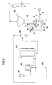
- Fig. 3
- schematically shows an embodiment of a polyolefine production process comprising a gas phase reactor with a control system for particle agglomeration.
- In a fluidized bed
gas phase reactor 100 an olefin is polymerized in the presence of a polymerization catalyst in an upwards moving gas stream. The reactor typically contains a fluidizedbed 10 comprising the growing polymer particles containing the active catalyst located above a fluidization grid. - The polymer bed is fluidized with the help of the
fluidization gas 2 comprising the olefin monomer, eventual comonomer(s), eventual chain growth controllers or chain transfer agents, such as hydrogen, and eventual inert gas. The fluidization gas is introduced into an inlet chamber at the bottom of thegas phase reactor 100. To make sure that the gas flow is uniformly distributed over the cross-sectional surface area of the inlet chamber the inlet pipe may be equipped with a flow dividing element as known in the art, e.g.US-A-4933149 andEP-A-684871 - From the inlet chamber the gas flow is passed upwards through a
fluidization grid 3 into thefluidized bed 10. The purpose of thefluidization grid 3 is to divide the gas flow evenly through the cross-sectional area of the bed. Sometimes thefluidization grid 3 may be arranged to establish a gas stream to sweep along the reactor walls, as disclosed inWO-A-2005/087361 . Other types offluidization grids 3 are disclosed, among others, inUS-A-4578879 ,EP 600414 EP-A-721798 - The fluidization gas passes through the
fluidized bed 10. The superficial velocity of the fluidization gas must be higher than the minimum fluidization velocity of the particles contained in thefluidized bed 10, as otherwise no fluidization would occur. On the other hand, the velocity of the gas should be lower than the onset velocity of pneumatic transport, as otherwise the whole bed would be entrained with the fluidization gas. The minimum fluidization velocity and the onset velocity of pneumatic transport can be calculated when the particle characteristics are know by using common engineering practice. An overview is given, among others in Geldart: Gas Fluidization Technology, J.Wiley & Sons, 1986. - When the fluidization gas is contacted with the bed containing the active catalyst the reactive components of the gas, such as monomers and chain transfer agents, react in the presence of the catalyst to produce the polymer product. At the same time the gas is heated by the reaction heat.
- The unreacted fluidization gas is removed from the top of the
gas phase reactor 100 and cooled in aheat exchanger 6 to remove the heat of reaction. The gas is cooled to a temperature which is lower than that of thebed 10 to prevent thebed 10 from heating because of the reaction. It is possible to cool the gas to a temperature where a part of it condenses. When the liquid droplets enter the reaction zone they are vaporized. The vaporization heat then contributes to the removal of the reaction heat. This kind of operation is called condensed mode and variations of it are disclosed, among others, inWO-A-2007/025640 ,US-A-4543399 ,EP-A-699213 WO-A-94/25495 EP-A-696293 - The gas is then compressed and recycled into the inlet chamber of the
gas phase reactor 100. Prior to the entry into the reactor fresh reactants are introduced into the fluidization gas stream to compensate for the losses caused by the reaction and product withdrawal. It is generally known to analyze the composition of the fluidization gas and introduce the gas components to keep the composition constant. The actual composition is determined by the desired properties of the product and the catalyst used in the polymerization. - The catalyst may be introduced into the reactor in various ways, either continuously or intermittently. Among others,
WO-A-01/05845 EP-A-499759 EP-A-1415999 andWO-A-00/26258 - The polymeric product may be withdrawn from the gas phase reactor either continuously or intermittently. Combinations of these methods may also be used. Continuous withdrawal is disclosed, among others, in
WO-A-00/29452 US-A-4621952 ,EP-A-188125 EP-A-250169 EP-A-579426 - The top part of the
gas phase reactor 100 may include a so called disengagement zone. In such a zone the diameter of the reactor is increased to reduce the gas velocity and allow the particles that are carried from the bed with the fluidization gas to settle back to the bed. - The bed level may be observed by different techniques known in the art. For instance, the pressure difference between the bottom of the reactor and a specific height of the bed may be recorded over the whole length of the reactor and the bed level may be calculated based on the pressure difference values. Such a calculation yields a time-averaged level. It is also possible to use ultrasonic sensors or radioactive sensors. With these methods instantaneous levels may be obtained, which of course may then be averaged over time to obtain time-averaged bed level.
- Also antistatic agent(s) may be introduced into the gas phase reactor if needed. Suitable antistatic agents and methods to use them are disclosed, among others, in
US-A-5026795 ,US-A-4803251 ,US-A-4532311 ,US-A-4855370 andEP-A-560035 - The reactor may also include a
mechanical agitator 1 to further facilitate mixing within the fluidized bed. An example of suitable agitator design is given inEP-A-707513 - In
Fig. 1 agas phase reactor 100 with afluidized bed 10 for manufacturing a polyolefine such as e.g. polyethylene or polypropylene is shown. Thefluidized bed 10 is situated in the lower part of thegas phase reactor 100. A fluidizinggas stream 2 is injected into the bottom of thegas phase reactor 100 through afluidization grid 3. - In the upper part (here with a disengaging space having larger diameter than the lower part) of the
gas phase reactor 100, the solid particles slow down so that they are separated to a large extent from the gas phase. - A
feed stream 4 to thegas phase reactor 100 comprises e.g. a relatively low molecular weight polymer from a loop reactor 210 (seeFig. 3 ). Thegas phase reactor 100 further comprisesproduct outlets continuous product outlet 9a has a relatively small diameter. Thebatch product outlet 9b has a relatively large diameter. The smallercontinuous product outlet 9a tends to become blocked first with agglomerations. The larger diameter of thebatch product outlet 9b allows for rapid emptying of thegas phase reactor 100 should it become necessary. - The
continuous product outlet 9a is typically located in the middle of thefluidized bed 10 so that the distance of thecontinuous product outlet 9a to thefluidization grid 3 is about 50 % of the total height of thefluidized bed 10. Thebatch product outlet 9b is typically located immediately above thefluidization grid 3. As the particle agglomerates are relatively heavy they tend to fall to thefluidization grid 3. Both 9a and 9b are used in normal operation. Thencontinuous product outlet 9a withdraws the main part of the polymer, whereas 9b is used to withdraw lumps from region of thefluidization grid 3. - The actuation time of the
batch product outlet 9b can be adjusted depending on how much particle agglomerations are formed. If no agglomerations are present then the flow through thebatch product outlet 9b may be adjusted to operate at a low frequency, e.g. once an hour. - The person skilled in the art will recognize that the position of the
feed stream 4 and theproduct outlets gas phase reactor 100 inFig. 1 is exemplary; other embodiments will have different arrangements. - At the top of the
gas phase reactor 100 gas, comprising some solid particles, is withdrawn through a gas circulation line and passed through a solid-gas separator 5 (e.g. a cyclone), a heat-exchanger 6 and a circulatinggas compressor 7. The pressurized gas and somefresh feed gas 8 then comprise the fluidizinggas stream 2. The person skilled in the art will recognize that this structural description of agas phase reactor 100 is exemplary so that other configurations are possible. - The
fluidized bed 10 of thegas phase reactor 100 comprises anagitation device 1 to impart mechanical energy into the solid-gas mixture of thefluidized bed 10. Theagitation device 1 in the depicted embodiment is a stirrer or mixer with a plurality of blades. Other embodiments use a different type of agitation device, e.g. an impeller with a single set of blades or an H-shaped anchor. - The
agitation device 1 in the embodiment shown is driven by anelectrical motor 11 as a driver. Theagitation device 1 and / or thedriver 11 of theagitation device 1 are coupled with a detection device 20 (e.g. a computer with inputs for measured data) which measures the at least one operational parameter of theagitation device 1. In this embodiment the operational parameter is the power consumption of themotor 11. In other embodiments operational parameters of theagitation device 1 could be measured at theagitation device 1 itself (e.g. rotational velocity) or at thedriver 11 of the agitation device 1 (e.g. torque). In general, any measureable parameter which allows the assessment of the performance or state of theagitation device 1, be it a direct measurement on theagitation device 1 or a connected device such as thedriver 11, is considered an operational parameter of theagitation device 1. - The measurement and processing of operational parameters, such as the power consumption allows the assessment of the particle agglomeration within the
gas phase reactor 100, in particular thefluidized bed 10. InFig. 2 the measured power consumption of thedriver 11 of theagitation device 1 in agas phase reactor 100 as described above in connection withFig. 1 is shown over approximately 14 days (between March 16, and March 31,). In this instance, the power consumption data is not filtered. - Approximately till March 26, the averaged power consumption is about 5 kW. The fluctuations around this mean value are about 10%. On March 27, the power consumption shows a change 30, i.e. an increase within a relatively short time (ca. 4h) to 7,3 kW (averaged) and remains at this level for about two days. This is an increase of 38% above the averaged power consumption level. The relatively sudden increase in the form of a step change has to be due to some internal changes within the
fluidized bed 10. Inspection of thegas phase reactor 100 showed particle agglomeration. - After two days at a level of 7,3 kW, the power consumption dropped, because some particle agglomerations were removed via the
batch product outlet 9b, but not to the previous level. On March 29, the power consumption increased to 7,6 kW and the process had to be stopped, i.e. thegas phase reactor 100 was shut down for cleaning. It showed that theproduct outlets agitation device 1 requiring the cleaning of the equipment. - This shows that a relatively sudden change in the power consumption of the
agitation device 1 is an efficient indicator of agglomeration formation. - In other cases the same behavior was observed, indicated by the following data:
Date Base level of power consumption Power consumption after change Change 09.03. 5 kW 6,5 kW +30% 07.04. 5 kW 6,5 kW +30% 29.04. 5,5 kW 6,7 kW +22% 21.05. 5 kW 6,7 kW +34% - A change, as described in this context is not limited to a step change. In other embodiments the change in an operational parameter can be an impulse, i.e. a sudden change of the parameter with a sudden drop of that change as well. An impulse might result in an increase of more than 30% for less than 15 minutes. Alternatively the change in an operational parameter can also be ramp signal, i.e. gradual build up (or slow down) of a parameter without a leveling.
- In some cases the changes in power consumption were detected during a grade change (i.e. a change in the type of polymer manufactured) and / or a change in the catalyst.
- Therefore, an embodiment of a
gas phase reactor 100 as shown inFig. 1 is coupled with adetection device 20 for detecting a change 30 in at least one operational parameter of theagitation device 1, here the power consumption of theagitation device 1. Thedetection device 20 receives regularly measurements e.g. of the power consumption and calculates an average value. When a change 30 in the power consumption of e.g. more than 10% above the averaged base line of the operational parameter is detected, acontrol signal 40 is being generated which is used to operate one or more manipulated variables to influence (e.g. retard, stop) the agglomeration in thegas phase reactor 100. Thedetection device 20 comprise means for the generation of at least onecontrol signal 40 in dependence of the detected change 30 so that the at least onecontrol signal 40 influences the state of thegas phase reactor 100, thefluidized bed 10 and / or theagitation device 1. The influencing is geared towards the reduction of agglomerations in thegas phase reactor 100 as will be explained below. - Alternatively the
control signal 40 can be generated if the change 30 as measured against a predetermined set point exceeds a certain threshold value. In this embodiment the averaging of the measured data is not necessary. - In a further embodiment the
detection device 20 comprises self-learning means, such as e.g. a neural net or a support vector machine to distinguish normal operation from abnormal operation. - The change 30 in the operational parameter can be a difference between two values, as mentioned above. But it could also be a change in the rates of the operational parameters. One example would be if the power consumption increases by a certain predetermined relative percentage over a certain predetermined time. This increase of power consumption is also an indicator for particle agglomeration. In other embodiments the vibration, torque and / or the rotational velocity of the
agitation device 1 is measured. Measurements can comprise the calculation of averaged measurements or integrated measurements, such as the integral squared error. With these measurements the importance of large but short changes or relatively small but long lasting changes can be assessed as the situation demands. - As in the case of the power consumption, changes 30 in vibration, torque and / or the rotational velocity are indicators of agglomerations in the
gas phase reactor 100. - The
detection device 20 is part of a control system for thegas phase reactor 100. In a simple embodiment, the generatedcontrol signal 40 triggers automatically a shut down of thegas phase reactor 100 for cleaning, i.e. the agglomerations have exceeded a certain threshold which requires the interruption of the process. - In another embodiment the generated
control signal 40 triggers automatically analarm system 43 which comprises a notification (e.g. warning light, print out and / or acoustic signal) for an operator. The operator can then take the appropriate measures, by e.g. shutting down thegas phase reactor 100 for cleaning. - Another possibility is to use the flow rates through the
product outlets - In further embodiment, the
control signal 40 acts upon a flow of apolymerization retarder 41, such as CO2 and / or CO. Furthermore oxygen, an oxygen containing gas and / or a sulphur containing gas can be used as retarders as well. Mixtures of the polymerization retarders are possible. - Since the change, i.e. the step increase in power consumption is an indicator of increased agglomeration, the control system counteracts this by introducing a polymerization retarder and thereby inhibiting the agglomeration of polymer particles. Once the measured power consumption is reduced to set point level, the polymerization retarder is reduced or switched off by the control system.
- In addition or alternatively, a flow of an
antistatic agent 42, comprising a ketone (e.g. up to C7, such e.g. acetone, methyl isobutyl ketone), an alcohol (e.g. C1 to C8 alcohols such as methanol, ethanol, isopropanol), water, an amine (e.g. N-alkyl-diethanolamines of formula: CH3(CH)nCH2-N(CH2CH2OH)2, wherein n is greater than 2), an amide and / or an ester (e.g. an hydroxyester, having at least two free hydroxyl groups, obtained from carboxylic acids having from 8 to 22 carbon atoms and from polyalcohol) can be used as manipulated variable to counteract the unwanted particle agglomeration. - In principle, other manipulated variables or combinations of manipulated variables can be functionally coupled with the
control signal 40 as long as those manipulated variables influence (e.g. stop, retard) the agglomeration of particles in thegas phase reactor 100, in particular within thefluidized bed 10. - A further embodiment is a process for catalytic production of polyolefines, in particular a BORSTAR process for producing polyethylene or polypropylene, in which at least one embodiment of a
gas phase reactor 100 is present. -
Gas phase reactors 100 are used in many polyolefine production processes. As an example for such a use a BORSTAR process with such agas phase reactor 100 is described inFig. 3 as a non-limiting example. In the art the BORSTAR process is well known, so that for the sake of brevity no detailed description is necessary here. - In
Fig. 3 one embodiment of a BORSTAR process for manufacturing polyethylene is shown. This flowsheet and the following description of the flowsheet are exemplary. A person skilled in the art will recognize that variations of the process in respect to the product (e.g. polypropylene), equipment and / or the operating conditions are possible. - The polymerization steps may be preceded by a prepolymerization step. The purpose of the prepolymerization is to polymerize a small amount of polymer onto the catalyst at a low temperature and/or a low monomer concentration. By prepolymerization it is possible to improve the performance of the catalyst in slurry and/or modify the properties of the final polymer. The prepolymerization step may be conducted in slurry or in gas phase. Preferably prepolymerization is conducted in slurry.
- Thus, the prepolymerization step may be conducted in a
loop reactor 200. The prepolymerization is then preferably conducted in an inert diluent, typically a hydrocarbon diluent such as methane, ethane, propane, n-butane, isobutane, pentanes, hexanes, heptanes, octanes etc., or their mixtures. Preferably the diluent is a low-boiling hydrocarbon having from 1 to 4 carbon atoms or a mixture of such hydrocarbons. The temperature in the prepolymerization step is typically from 0 to 90 °C, preferably from 20 to 70 °C. - A
pre-polymerization reactor 200 is used to start the catalytic polymerization process as well as to develop the desired particles. The feed streams to thepre-polymerization reactor 200 are catalysts from astorage 201 and thefeedstock 202 for the polyolefine production, e.g. ethylene, diluent, an eventual comonomer and hydrogen. Typical operating conditions of thepre-polymerization reactor 200 are pressures between 50 and 100 bars, temperatures between 50 and 100°C and residence times between 10 to 50 minutes. - The product of the
pre-polymerization 200 is the feed stream of aloop reactor 210 which generally produces a low molecular weight polymer with a relative narrow molecular weight distribution. Supercritical propane is used as a diluent resulting in a low solubility of the polyethylene in the diluent. - The polymerization in a first polymerization zone may be conducted in slurry. Then the polymer particles formed in the polymerization, together with the catalyst fragmented and dispersed within the particles, are suspended in the fluid hydrocarbon. The slurry is agitated to enable the transfer of reactants from the fluid into the particles.
- The polymerization usually takes place in an inert diluent, typically a hydrocarbon diluent such as methane, ethane, propane, n-butane, isobutane, pentanes, hexanes, heptanes, octanes etc., or their mixtures. Preferably the diluent is a low-boiling hydrocarbon having from 1 to 4 carbon atoms or a mixture of such hydrocarbons. An especially preferred diluent is propane, possibly containing minor amount of methane, ethane and/or butane.
- The ethylene content in the fluid phase of the slurry may be from 2 to about 50 % by mole, preferably from about 3 to about 20 % by mole and in particular from about 5 to about 15 % by mole. The benefit of having a high ethylene concentration is that the productivity of the catalyst is increased but the drawback is that more ethylene then needs to be recycled than if the concentration was lower.
- The temperature in the slurry polymerization is typically from 50 to 115 °C, preferably from 60 to 110 °C and in particular from 70 to 100 °C. The pressure is from 1 to 150 bar, preferably from 10 to 100 bar.
- The slurry polymerization may be conducted in any known reactor used for slurry polymerization. Such reactors include a continuous stirred tank reactor and a
loop reactor 210. It is especially preferred to conduct the polymerization inloop reactor 210. In such reactors the slurry is circulated with a high velocity along a closed pipe by using a circulation pump. Loop reactors are generally known in the art and examples are given, for instance, inUS-A-4582816 ,US-A-3405109 ,US-A-3324093 ,EP-A-479186 US-A-5391654 . - It is sometimes advantageous to conduct the slurry polymerization above the critical temperature and pressure of the fluid mixture. Such operation is described in
US-A-5391654 . In such operation the temperature is typically from 85 to 110 °C, preferably from 90 to 105 °C and the pressure is from 40 to 150 bar, preferably from 50 to 100 bar. - The slurry may be withdrawn from the reactor either continuously or intermittently. A preferred way of intermittent withdrawal is the use of settling legs where slurry is allowed to concentrate before withdrawing a batch of the concentrated slurry from the reactor. The use of settling legs is disclosed, among others, in
US-A-3374211 ,US-A-3242150 andEP-A-1310295 . Continuous withdrawal is disclosed, among others, inEP-A-891990 EP-A-1415999 ,EP-A-1591460 andWO-A-2007/025640 . The continuous withdrawal is advantageously combined with a suitable concentration method, as disclosed inEP-A-1310295 andEP-A-1591460 . - Typically the
loop reactor 210 in this embodiment operates at 50 to 100 bars, and at temperatures between 70 and 105°C. The residence time in theloop reactor 210 is between 0,5 and 1 h. - The product of the
loop reactor 210 is then passed through a gas-solid separator 220. The gaseous diluent is fed back to the loop-reactor 210 after bringing it back into supercritical state. - The solids from the
separator 220 are fed into thegas phase reactor 100 in which high molecular weight polymer within an accurate molecular weight distribution is produced. Thegas phase reactor 100 with alternative embodiments and thedetection device 20 is described in connection withFig. 1 so that reference is made to said description. - The embodiment of the
gas phase reactor 100 shown inFig. 3 typically operates at a lower pressure than theloop reactor 210, e.g. between 10 and 35 bar. The temperatures are in the same range as in theloop reactor 210, e.g. between 70 and 90°C. The residence time is between 1 to 3h. - In the embodiments shown in
Fig. 3 thegas phase reactor 100 is integrated into the BORSTAR process. Thedetection device 20 is used to measure an operational parameter of theagitation device 1, i.e. the power consumption. This information is used to generate a control signal which can act onfeed lines gas phase reactor 100. Thecontrol signal 40 can also act on twooutlet streams gas phase reactor 100. The person skilled in the art will recognize that control scheme of thegas phase reactor 100 can use one or more manipulated variables. It is also possible that thedetection device 20 is coupled with a mathematical model of the process allowing model predictive control. - In any case, a change 30 in the power consumption is used as an indicator for particle agglomeration. The control signals 40 provide measures to act against this particle agglomeration.
- 1
- Agitation device
- 2
- Fluidizing gas stream
- 3
- Fluidization grid
- 4
- Feed stream to gas phase reactor
- 5
- Gas-solid separator
- 6
- Heat exchanger
- 7
- Circulating gas compressor
- 8
- Fresh gas supply line
- 9a
- Continuous product outlet
- 9b
- Batch product outlet
- 10
- Fluidized bed
- 11
- Motor for agitation device
- 20
- Detection device
- 30
- Change in operational parameter of the agitation device
- 40
- Control signal
- 41
- Flow of polymerization retarder
- 42
- Flow of antistatic agent
- 43
- Alarm system
- 100
- Gas phase reactor
- 200
- Pre-polymerization reactor
- 202
- Feed flow to pre-polymerization reactor
- 201
- Catalyst storage
- 210
- Loop reactor
- 220
- Gas-solid separator
Claims (15)
- Control system for a fluidized bed gas phase reactor (100) for the catalytic production of polyolefines having at least one agitation device (1) in a fluidized bed (10) in a gas phase reactor (100),
characterized by
a detection device (20) for detecting a change (30) in at least one operational parameter of the agitation device (1), in particular the vibration, torque and / or the power consumption of the agitation device (1), the detection device (20) comprising means for the generation of at least one control signal (40) in dependence on the change (30), the control signal (40) acting on a manipulated variable of the gas phase reactor (100), the fluidized bed (10) and / or the agitation device (1) to influence the formation of particle agglomerations in the gas phase reactor (100) and / or the removal of particle agglomerations from the gas phase reactor (100). - Control system according to claim 1, wherein the change (30) in the at least one operational parameter is an absolute or relative deviation from previously measured operational data of the agitation device (1) by a predefined amount or an absolute or relative deviation from previously measured operational data of the agitation device (1) by a predefined amount within a predefined time and / or a rate of change in the operational data of the agitation device (1), the change (30) exceeding a predefined criterion.
- Control system according to claim 1 or 2, wherein the change (30) in the at least one operational parameter is a step change in the power consumption of the agitation device (1) of more than 10% over a period of more than 30 minutes, an impulse or a ramp signal
- Control system according to any of the preceding claims, wherein the measured operational data of the agitation device (1) is filtered, integrated, averaged and / or processed by a self-learning data processor.
- Control system according to any of the preceding claims, wherein the control signal (40) is functionally coupled to a flowrate of a withdrawl stream (9a, 9b) from the gas phase reactor (100) and / or a processor for the shutdown of the gas phase reactor, a flowrate of a polymerization retarder (41), a flowrate of a antistatic agent (42) and / or an alarm system (43) for an operator.
- Gas phase reactor for the catalytic production of polyolefines, in particular polyethylene or polypropylene, comprising a control system according to at least one of the claims 1 to 5.
- Gas phase reactor according to claim 6, wherein the agitation device (1) comprises a stirrer.
- Gas phase reactor according to claim 6 or 7, wherein the control signal (40) is functionally coupled with a flowrate of a polymerization retarder (41), a flowrate of an antistatic agent (42), a flowrate of a withdrawl stream (9a, 9b) from the gas phase reactor (100) and / or a processor for the shutdown of the gas phase reactor.
- Gas phase reactor accoring to any of the claims 6 to 8, wherein the control signal (40) is functionally coupled to an alarm system (43).
- Gas phase reactor according to any of the claims 6 to 9, comprising a feed of a polymerization retarder (41), the polymerization retarder comprising CO2 CO, oxygen, an oxygen containing gas and / or a sulphur containing gas.
- Gas phase reactor according to any of the claims 6 to 10, comprising a feed of an antistatic agent (42), the antistatic agent (42) comprising a ketone, an alcohol, water, an amine, an amide and / or an ester.
- Method for a catalytic production of polyolefines, in particular a BORSTAR process for producing polyethylene or polypropylene comprising at least one gas phase reactor (100) according to at least one of the claims 6 to 11.
- Method according to claim 12, wherein the average pressure in the at least one gas phase reactor (100) is between 10 and 40 bar and the average temperature is in the range between 60 and 110°C.
- Method according to claim 12 or 13, wherein the process is carried out by using at least one loop reactor (210) providing at least one feed stream for the at least one gas phase reactor (100).
- Use of a control system according to any of the claims 1 to 5 in an arrangement for the production of polyolefines, in particular polyethylene or polypropylene.
Priority Applications (2)
| Application Number | Priority Date | Filing Date | Title |
|---|---|---|---|
| ES10166314.4T ES2624858T3 (en) | 2010-06-17 | 2010-06-17 | Control system for a gas phase reactor, a gas phase reactor for the catalytic production of polyolefins, a method for catalytic productions of polyolefins and a use of the control system |
| EP10166314.4A EP2397221B1 (en) | 2010-06-17 | 2010-06-17 | Control system for a gas phase reactor, a gas phase reactor for catalytic production of polyolefines, a method for catalytic productions of polyolefines and a use of the control system |
Applications Claiming Priority (1)
| Application Number | Priority Date | Filing Date | Title |
|---|---|---|---|
| EP10166314.4A EP2397221B1 (en) | 2010-06-17 | 2010-06-17 | Control system for a gas phase reactor, a gas phase reactor for catalytic production of polyolefines, a method for catalytic productions of polyolefines and a use of the control system |
Publications (2)
| Publication Number | Publication Date |
|---|---|
| EP2397221A1 true EP2397221A1 (en) | 2011-12-21 |
| EP2397221B1 EP2397221B1 (en) | 2017-04-12 |
Family
ID=42938601
Family Applications (1)
| Application Number | Title | Priority Date | Filing Date |
|---|---|---|---|
| EP10166314.4A Active EP2397221B1 (en) | 2010-06-17 | 2010-06-17 | Control system for a gas phase reactor, a gas phase reactor for catalytic production of polyolefines, a method for catalytic productions of polyolefines and a use of the control system |
Country Status (2)
| Country | Link |
|---|---|
| EP (1) | EP2397221B1 (en) |
| ES (1) | ES2624858T3 (en) |
Cited By (1)
| Publication number | Priority date | Publication date | Assignee | Title |
|---|---|---|---|---|
| EP4001249A4 (en) * | 2020-09-22 | 2022-09-21 | LG Chem, Ltd. | Apparatus for preparing oligomer |
Citations (42)
| Publication number | Priority date | Publication date | Assignee | Title |
|---|---|---|---|---|
| US3242150A (en) | 1960-03-31 | 1966-03-22 | Phillips Petroleum Co | Method and apparatus for the recovery of solid olefin polymer from a continuous path reaction zone |
| US3275809A (en) * | 1957-12-04 | 1966-09-27 | Phillips Petroleum Co | Measurement and control of polymerization reactions |
| US3324093A (en) | 1963-10-21 | 1967-06-06 | Phillips Petroleum Co | Loop reactor |
| US3374211A (en) | 1964-07-27 | 1968-03-19 | Phillips Petroleum Co | Solids recovery from a flowing stream |
| US3405109A (en) | 1960-10-03 | 1968-10-08 | Phillips Petroleum Co | Polymerization process |
| US3544540A (en) * | 1968-11-12 | 1970-12-01 | Phillips Petroleum Co | Temperature control system |
| US4532311A (en) | 1981-03-26 | 1985-07-30 | Union Carbide Corporation | Process for reducing sheeting during polymerization of alpha-olefins |
| US4543399A (en) | 1982-03-24 | 1985-09-24 | Union Carbide Corporation | Fluidized bed reaction systems |
| US4578879A (en) | 1983-11-08 | 1986-04-01 | Mitsui Engineering And Shipbuilding Co., Ltd. | Fluidizing apparatus |
| US4582816A (en) | 1985-02-21 | 1986-04-15 | Phillips Petroleum Company | Catalysts, method of preparation and polymerization processes therewith |
| EP0188125A2 (en) | 1984-12-31 | 1986-07-23 | Mobil Oil Corporation | Closed loop recycle of vent gas in polymerization process |
| US4621952A (en) | 1981-07-28 | 1986-11-11 | Union Carbide Corporation | Fluidized bed discharge process |
| EP0233787A1 (en) | 1986-02-19 | 1987-08-26 | BP Chemicals Limited | The detection of anomolies in gas fluidised bed polymerisation |
| EP0250169A2 (en) | 1986-06-16 | 1987-12-23 | BP Chemicals Limited | Fluidised bed discharge device |
| US4803251A (en) | 1987-11-04 | 1989-02-07 | Union Carbide Corporation | Method for reducing sheeting during polymerization of alpha-olefins |
| US4855370A (en) | 1986-10-01 | 1989-08-08 | Union Carbide Corporation | Method for reducing sheeting during polymerization of alpha-olefins |
| US4933149A (en) | 1984-08-24 | 1990-06-12 | Union Carbide Chemicals And Plastics Company Inc. | Fluidized bed polymerization reactors |
| EP0432555A2 (en) * | 1989-11-27 | 1991-06-19 | Phillips Petroleum Company | Control of polymerization reaction |
| US5026795A (en) | 1987-02-24 | 1991-06-25 | Phillips Petroleum Co | Process for preventing fouling in a gas phase polymerization reactor |
| EP0479186A2 (en) | 1990-10-01 | 1992-04-08 | Phillips Petroleum Company | Apparatus and method for producing ethylene polymer |
| EP0499759A1 (en) | 1991-02-21 | 1992-08-26 | Bp Chemicals S.N.C. | Process for monitoring flow in a pneumatic conveying system |
| EP0560035A1 (en) | 1992-01-31 | 1993-09-15 | Montell Technology Company bv | Process for the gas-phase polymerization of alpha-olefins |
| EP0579426A1 (en) | 1992-07-16 | 1994-01-19 | BP Chemicals Limited | Polymerization process |
| EP0600414A1 (en) | 1992-11-30 | 1994-06-08 | Sumitomo Chemical Company, Limited | Gas distributor for use in gas phase polymerization apparatus |
| WO1994025495A1 (en) | 1993-05-20 | 1994-11-10 | Exxon Chemical Patents Inc. | Process for polymerizing monomers in fluidized beds |
| US5391654A (en) | 1990-12-28 | 1995-02-21 | Neste Oy | Method for homo- or copolymerizing ethene |
| EP0684871A1 (en) | 1993-12-27 | 1995-12-06 | Borealis Polymers Oy | Fluidized-bed reactor |
| EP0696293A1 (en) | 1993-04-26 | 1996-02-14 | Exxon Chemical Patents Inc. | Process for polymerizing monomers in fluidized beds |
| EP0699213A1 (en) | 1993-05-20 | 1996-03-06 | BP Chemicals Limited | Polymerisation process |
| EP0707513A1 (en) | 1993-07-05 | 1996-04-24 | Borealis Polymers Oy | Method for polymerizing olefins in a fluid-bed reactor |
| EP0721798A2 (en) | 1994-12-28 | 1996-07-17 | Mitsui Petrochemical Industries, Ltd. | Gas distributor plate for a gas phase polymerisation apparatus |
| EP0891990A2 (en) | 1997-07-15 | 1999-01-20 | Phillips Petroleum Company | High solids slurry polymerization |
| WO2000026258A1 (en) | 1998-11-04 | 2000-05-11 | Borealis Technology Oy | Method for eliminating static electricity |
| WO2000029452A1 (en) | 1998-11-12 | 2000-05-25 | Borealis Technology Oy | Method and apparatus for discharging polymerization reactors |
| CH690492A5 (en) * | 1995-01-12 | 2000-09-29 | Glatt Maschinen & Apparatebau | Fuidization process optionally treating, agglomerating, drying and coating particles is controlled from a measured agitation power, which is related through particle impacts, to their moisture content |
| WO2001005845A1 (en) | 1999-07-14 | 2001-01-25 | Union Carbide Chemicals & Plastics Technology Corporation | Process for the preparation of polyethylene |
| EP1106629A1 (en) | 1999-12-10 | 2001-06-13 | Sumitomo Chemical Company, Limited | Method and apparatus for detecting agglomerates |
| EP1310295A1 (en) | 2001-10-30 | 2003-05-14 | Borealis Technology Oy | Polymerisation reactor |
| EP1415999A1 (en) | 2002-10-30 | 2004-05-06 | Borealis Technology Oy | Process and apparatus for producing olefin polymers |
| WO2005087361A1 (en) | 2004-03-15 | 2005-09-22 | Borealis Technology Oy | Method and apparatus for producing polymers |
| EP1591460A1 (en) | 2004-04-29 | 2005-11-02 | Borealis Technology Oy | Process for producing polyethylene |
| WO2007025640A1 (en) | 2005-09-02 | 2007-03-08 | Borealis Technology Oy | Process for polymerizing olefins in the presence of an olefin polymerization catalyst |
-
2010
- 2010-06-17 EP EP10166314.4A patent/EP2397221B1/en active Active
- 2010-06-17 ES ES10166314.4T patent/ES2624858T3/en active Active
Patent Citations (42)
| Publication number | Priority date | Publication date | Assignee | Title |
|---|---|---|---|---|
| US3275809A (en) * | 1957-12-04 | 1966-09-27 | Phillips Petroleum Co | Measurement and control of polymerization reactions |
| US3242150A (en) | 1960-03-31 | 1966-03-22 | Phillips Petroleum Co | Method and apparatus for the recovery of solid olefin polymer from a continuous path reaction zone |
| US3405109A (en) | 1960-10-03 | 1968-10-08 | Phillips Petroleum Co | Polymerization process |
| US3324093A (en) | 1963-10-21 | 1967-06-06 | Phillips Petroleum Co | Loop reactor |
| US3374211A (en) | 1964-07-27 | 1968-03-19 | Phillips Petroleum Co | Solids recovery from a flowing stream |
| US3544540A (en) * | 1968-11-12 | 1970-12-01 | Phillips Petroleum Co | Temperature control system |
| US4532311A (en) | 1981-03-26 | 1985-07-30 | Union Carbide Corporation | Process for reducing sheeting during polymerization of alpha-olefins |
| US4621952A (en) | 1981-07-28 | 1986-11-11 | Union Carbide Corporation | Fluidized bed discharge process |
| US4543399A (en) | 1982-03-24 | 1985-09-24 | Union Carbide Corporation | Fluidized bed reaction systems |
| US4578879A (en) | 1983-11-08 | 1986-04-01 | Mitsui Engineering And Shipbuilding Co., Ltd. | Fluidizing apparatus |
| US4933149A (en) | 1984-08-24 | 1990-06-12 | Union Carbide Chemicals And Plastics Company Inc. | Fluidized bed polymerization reactors |
| EP0188125A2 (en) | 1984-12-31 | 1986-07-23 | Mobil Oil Corporation | Closed loop recycle of vent gas in polymerization process |
| US4582816A (en) | 1985-02-21 | 1986-04-15 | Phillips Petroleum Company | Catalysts, method of preparation and polymerization processes therewith |
| EP0233787A1 (en) | 1986-02-19 | 1987-08-26 | BP Chemicals Limited | The detection of anomolies in gas fluidised bed polymerisation |
| EP0250169A2 (en) | 1986-06-16 | 1987-12-23 | BP Chemicals Limited | Fluidised bed discharge device |
| US4855370A (en) | 1986-10-01 | 1989-08-08 | Union Carbide Corporation | Method for reducing sheeting during polymerization of alpha-olefins |
| US5026795A (en) | 1987-02-24 | 1991-06-25 | Phillips Petroleum Co | Process for preventing fouling in a gas phase polymerization reactor |
| US4803251A (en) | 1987-11-04 | 1989-02-07 | Union Carbide Corporation | Method for reducing sheeting during polymerization of alpha-olefins |
| EP0432555A2 (en) * | 1989-11-27 | 1991-06-19 | Phillips Petroleum Company | Control of polymerization reaction |
| EP0479186A2 (en) | 1990-10-01 | 1992-04-08 | Phillips Petroleum Company | Apparatus and method for producing ethylene polymer |
| US5391654A (en) | 1990-12-28 | 1995-02-21 | Neste Oy | Method for homo- or copolymerizing ethene |
| EP0499759A1 (en) | 1991-02-21 | 1992-08-26 | Bp Chemicals S.N.C. | Process for monitoring flow in a pneumatic conveying system |
| EP0560035A1 (en) | 1992-01-31 | 1993-09-15 | Montell Technology Company bv | Process for the gas-phase polymerization of alpha-olefins |
| EP0579426A1 (en) | 1992-07-16 | 1994-01-19 | BP Chemicals Limited | Polymerization process |
| EP0600414A1 (en) | 1992-11-30 | 1994-06-08 | Sumitomo Chemical Company, Limited | Gas distributor for use in gas phase polymerization apparatus |
| EP0696293A1 (en) | 1993-04-26 | 1996-02-14 | Exxon Chemical Patents Inc. | Process for polymerizing monomers in fluidized beds |
| WO1994025495A1 (en) | 1993-05-20 | 1994-11-10 | Exxon Chemical Patents Inc. | Process for polymerizing monomers in fluidized beds |
| EP0699213A1 (en) | 1993-05-20 | 1996-03-06 | BP Chemicals Limited | Polymerisation process |
| EP0707513A1 (en) | 1993-07-05 | 1996-04-24 | Borealis Polymers Oy | Method for polymerizing olefins in a fluid-bed reactor |
| EP0684871A1 (en) | 1993-12-27 | 1995-12-06 | Borealis Polymers Oy | Fluidized-bed reactor |
| EP0721798A2 (en) | 1994-12-28 | 1996-07-17 | Mitsui Petrochemical Industries, Ltd. | Gas distributor plate for a gas phase polymerisation apparatus |
| CH690492A5 (en) * | 1995-01-12 | 2000-09-29 | Glatt Maschinen & Apparatebau | Fuidization process optionally treating, agglomerating, drying and coating particles is controlled from a measured agitation power, which is related through particle impacts, to their moisture content |
| EP0891990A2 (en) | 1997-07-15 | 1999-01-20 | Phillips Petroleum Company | High solids slurry polymerization |
| WO2000026258A1 (en) | 1998-11-04 | 2000-05-11 | Borealis Technology Oy | Method for eliminating static electricity |
| WO2000029452A1 (en) | 1998-11-12 | 2000-05-25 | Borealis Technology Oy | Method and apparatus for discharging polymerization reactors |
| WO2001005845A1 (en) | 1999-07-14 | 2001-01-25 | Union Carbide Chemicals & Plastics Technology Corporation | Process for the preparation of polyethylene |
| EP1106629A1 (en) | 1999-12-10 | 2001-06-13 | Sumitomo Chemical Company, Limited | Method and apparatus for detecting agglomerates |
| EP1310295A1 (en) | 2001-10-30 | 2003-05-14 | Borealis Technology Oy | Polymerisation reactor |
| EP1415999A1 (en) | 2002-10-30 | 2004-05-06 | Borealis Technology Oy | Process and apparatus for producing olefin polymers |
| WO2005087361A1 (en) | 2004-03-15 | 2005-09-22 | Borealis Technology Oy | Method and apparatus for producing polymers |
| EP1591460A1 (en) | 2004-04-29 | 2005-11-02 | Borealis Technology Oy | Process for producing polyethylene |
| WO2007025640A1 (en) | 2005-09-02 | 2007-03-08 | Borealis Technology Oy | Process for polymerizing olefins in the presence of an olefin polymerization catalyst |
Non-Patent Citations (1)
| Title |
|---|
| GELDART; BAYENS, DESIGN OF DISTRIBUTORS FOR GAS-FLUIDIZED BEDS, POWDER TECHNOLOGY, vol. 42, 1985 |
Cited By (2)
| Publication number | Priority date | Publication date | Assignee | Title |
|---|---|---|---|---|
| EP4001249A4 (en) * | 2020-09-22 | 2022-09-21 | LG Chem, Ltd. | Apparatus for preparing oligomer |
| US11904291B2 (en) | 2020-09-22 | 2024-02-20 | Lg Chem, Ltd. | Apparatus for preparing oligomer |
Also Published As
| Publication number | Publication date |
|---|---|
| EP2397221B1 (en) | 2017-04-12 |
| ES2624858T3 (en) | 2017-07-17 |
Similar Documents
| Publication | Publication Date | Title |
|---|---|---|
| US7774178B2 (en) | Methods for on-line determination of degree of resin stickiness using a model for depression of melt initiation temperature | |
| WO1997004015A1 (en) | Process and apparatus for the gas-phase polymerization of alpha-olefins | |
| US20070036692A1 (en) | Olefin polymerization process with optimized product discharge | |
| CA2662796A1 (en) | Methods for determining temperature value indicative of resin stickiness from data generated by polymerization reaction monitoring | |
| CN101888898A (en) | Reactor system and process for the catalytic polymerization of olefins, and the use of such reactor system in catalytic polimerization of olefins | |
| US11065595B2 (en) | System and method for monitoring and controlling a polymerization system | |
| EP2594333B1 (en) | Method for recovering polymer and apparatus therefor | |
| EP2397221B1 (en) | Control system for a gas phase reactor, a gas phase reactor for catalytic production of polyolefines, a method for catalytic productions of polyolefines and a use of the control system | |
| EP2331249B1 (en) | Methods for cleaning the distributor plate in a fluidized bed reactor system | |
| US9334336B2 (en) | Polyolefin reactor system having a gas phase reactor and solids recovery | |
| EP3548519B1 (en) | Process | |
| JP2009126908A (en) | Polymerizer | |
| EP2528953B1 (en) | Process for the gas phase polymerisation of olefins | |
| CN101883628A (en) | Reactor system for the catalytic polymerization of olefins comprising shielding means and a process and use thereof | |
| US9433914B2 (en) | Polyolefin reactor system having a gas phase reactor | |
| Ghasem et al. | Dynamics and stability of ethylene polymerization in multizone circulating reactors | |
| CN109937213B (en) | Process for preparing polyolefins by discontinuous addition of thermal runaway reducers | |
| CN102958598A (en) | Interlock and process | |
| US20230001374A1 (en) | System for Producing Polyolefin and Process for Recovering Polymerization Product from Gas Phase Reactor | |
| Joseph Schork | Design and Operation of Polymerization Reactors | |
| EP2674213A1 (en) | Method for cooling a gas-phase reactor for the polymerization of olefins | |
| EP2880066B1 (en) | Polymerisation process | |
| AU719107C (en) | Process and apparatus for the gas-phase polymerization of alpha-olefins | |
| EP2084478A1 (en) | System for fluidizing solid particles including novel outlet for vessel | |
| WO2018046395A1 (en) | Process of preparing polyolefin with the discontinuous addition of a thermal runaway reducing agent |
Legal Events
| Date | Code | Title | Description |
|---|---|---|---|
| AK | Designated contracting states |
Kind code of ref document: A1 Designated state(s): AL AT BE BG CH CY CZ DE DK EE ES FI FR GB GR HR HU IE IS IT LI LT LU LV MC MK MT NL NO PL PT RO SE SI SK SM TR |
|
| AX | Request for extension of the european patent |
Extension state: BA ME RS |
|
| PUAI | Public reference made under article 153(3) epc to a published international application that has entered the european phase |
Free format text: ORIGINAL CODE: 0009012 |
|
| 17P | Request for examination filed |
Effective date: 20120522 |
|
| 17Q | First examination report despatched |
Effective date: 20120921 |
|
| GRAP | Despatch of communication of intention to grant a patent |
Free format text: ORIGINAL CODE: EPIDOSNIGR1 |
|
| INTG | Intention to grant announced |
Effective date: 20161103 |
|
| GRAS | Grant fee paid |
Free format text: ORIGINAL CODE: EPIDOSNIGR3 |
|
| GRAA | (expected) grant |
Free format text: ORIGINAL CODE: 0009210 |
|
| AK | Designated contracting states |
Kind code of ref document: B1 Designated state(s): AL AT BE BG CH CY CZ DE DK EE ES FI FR GB GR HR HU IE IS IT LI LT LU LV MC MK MT NL NO PL PT RO SE SI SK SM TR |
|
| REG | Reference to a national code |
Ref country code: GB Ref legal event code: FG4D |
|
| REG | Reference to a national code |
Ref country code: CH Ref legal event code: EP |
|
| REG | Reference to a national code |
Ref country code: IE Ref legal event code: FG4D |
|
| REG | Reference to a national code |
Ref country code: AT Ref legal event code: REF Ref document number: 883306 Country of ref document: AT Kind code of ref document: T Effective date: 20170515 |
|
| REG | Reference to a national code |
Ref country code: DE Ref legal event code: R096 Ref document number: 602010041428 Country of ref document: DE |
|
| REG | Reference to a national code |
Ref country code: FR Ref legal event code: PLFP Year of fee payment: 8 |
|
| REG | Reference to a national code |
Ref country code: ES Ref legal event code: FG2A Ref document number: 2624858 Country of ref document: ES Kind code of ref document: T3 Effective date: 20170717 |
|
| REG | Reference to a national code |
Ref country code: NL Ref legal event code: FP |
|
| REG | Reference to a national code |
Ref country code: LT Ref legal event code: MG4D |
|
| REG | Reference to a national code |
Ref country code: AT Ref legal event code: MK05 Ref document number: 883306 Country of ref document: AT Kind code of ref document: T Effective date: 20170412 |
|
| PG25 | Lapsed in a contracting state [announced via postgrant information from national office to epo] |
Ref country code: FI Free format text: LAPSE BECAUSE OF FAILURE TO SUBMIT A TRANSLATION OF THE DESCRIPTION OR TO PAY THE FEE WITHIN THE PRESCRIBED TIME-LIMIT Effective date: 20170412 Ref country code: LT Free format text: LAPSE BECAUSE OF FAILURE TO SUBMIT A TRANSLATION OF THE DESCRIPTION OR TO PAY THE FEE WITHIN THE PRESCRIBED TIME-LIMIT Effective date: 20170412 Ref country code: HR Free format text: LAPSE BECAUSE OF FAILURE TO SUBMIT A TRANSLATION OF THE DESCRIPTION OR TO PAY THE FEE WITHIN THE PRESCRIBED TIME-LIMIT Effective date: 20170412 Ref country code: GR Free format text: LAPSE BECAUSE OF FAILURE TO SUBMIT A TRANSLATION OF THE DESCRIPTION OR TO PAY THE FEE WITHIN THE PRESCRIBED TIME-LIMIT Effective date: 20170713 Ref country code: NO Free format text: LAPSE BECAUSE OF FAILURE TO SUBMIT A TRANSLATION OF THE DESCRIPTION OR TO PAY THE FEE WITHIN THE PRESCRIBED TIME-LIMIT Effective date: 20170712 Ref country code: AT Free format text: LAPSE BECAUSE OF FAILURE TO SUBMIT A TRANSLATION OF THE DESCRIPTION OR TO PAY THE FEE WITHIN THE PRESCRIBED TIME-LIMIT Effective date: 20170412 |
|
| PG25 | Lapsed in a contracting state [announced via postgrant information from national office to epo] |
Ref country code: PL Free format text: LAPSE BECAUSE OF FAILURE TO SUBMIT A TRANSLATION OF THE DESCRIPTION OR TO PAY THE FEE WITHIN THE PRESCRIBED TIME-LIMIT Effective date: 20170412 Ref country code: BG Free format text: LAPSE BECAUSE OF FAILURE TO SUBMIT A TRANSLATION OF THE DESCRIPTION OR TO PAY THE FEE WITHIN THE PRESCRIBED TIME-LIMIT Effective date: 20170712 Ref country code: SE Free format text: LAPSE BECAUSE OF FAILURE TO SUBMIT A TRANSLATION OF THE DESCRIPTION OR TO PAY THE FEE WITHIN THE PRESCRIBED TIME-LIMIT Effective date: 20170412 Ref country code: IS Free format text: LAPSE BECAUSE OF FAILURE TO SUBMIT A TRANSLATION OF THE DESCRIPTION OR TO PAY THE FEE WITHIN THE PRESCRIBED TIME-LIMIT Effective date: 20170812 Ref country code: LV Free format text: LAPSE BECAUSE OF FAILURE TO SUBMIT A TRANSLATION OF THE DESCRIPTION OR TO PAY THE FEE WITHIN THE PRESCRIBED TIME-LIMIT Effective date: 20170412 |
|
| REG | Reference to a national code |
Ref country code: DE Ref legal event code: R097 Ref document number: 602010041428 Country of ref document: DE |
|
| PG25 | Lapsed in a contracting state [announced via postgrant information from national office to epo] |
Ref country code: DK Free format text: LAPSE BECAUSE OF FAILURE TO SUBMIT A TRANSLATION OF THE DESCRIPTION OR TO PAY THE FEE WITHIN THE PRESCRIBED TIME-LIMIT Effective date: 20170412 Ref country code: CZ Free format text: LAPSE BECAUSE OF FAILURE TO SUBMIT A TRANSLATION OF THE DESCRIPTION OR TO PAY THE FEE WITHIN THE PRESCRIBED TIME-LIMIT Effective date: 20170412 Ref country code: SK Free format text: LAPSE BECAUSE OF FAILURE TO SUBMIT A TRANSLATION OF THE DESCRIPTION OR TO PAY THE FEE WITHIN THE PRESCRIBED TIME-LIMIT Effective date: 20170412 Ref country code: MC Free format text: LAPSE BECAUSE OF FAILURE TO SUBMIT A TRANSLATION OF THE DESCRIPTION OR TO PAY THE FEE WITHIN THE PRESCRIBED TIME-LIMIT Effective date: 20170412 Ref country code: RO Free format text: LAPSE BECAUSE OF FAILURE TO SUBMIT A TRANSLATION OF THE DESCRIPTION OR TO PAY THE FEE WITHIN THE PRESCRIBED TIME-LIMIT Effective date: 20170412 Ref country code: EE Free format text: LAPSE BECAUSE OF FAILURE TO SUBMIT A TRANSLATION OF THE DESCRIPTION OR TO PAY THE FEE WITHIN THE PRESCRIBED TIME-LIMIT Effective date: 20170412 |
|
| REG | Reference to a national code |
Ref country code: CH Ref legal event code: PL |
|
| PLBE | No opposition filed within time limit |
Free format text: ORIGINAL CODE: 0009261 |
|
| STAA | Information on the status of an ep patent application or granted ep patent |
Free format text: STATUS: NO OPPOSITION FILED WITHIN TIME LIMIT |
|
| PG25 | Lapsed in a contracting state [announced via postgrant information from national office to epo] |
Ref country code: SM Free format text: LAPSE BECAUSE OF FAILURE TO SUBMIT A TRANSLATION OF THE DESCRIPTION OR TO PAY THE FEE WITHIN THE PRESCRIBED TIME-LIMIT Effective date: 20170412 |
|
| 26N | No opposition filed |
Effective date: 20180115 |
|
| REG | Reference to a national code |
Ref country code: IE Ref legal event code: MM4A |
|
| PG25 | Lapsed in a contracting state [announced via postgrant information from national office to epo] |
Ref country code: IE Free format text: LAPSE BECAUSE OF NON-PAYMENT OF DUE FEES Effective date: 20170617 Ref country code: LU Free format text: LAPSE BECAUSE OF NON-PAYMENT OF DUE FEES Effective date: 20170617 Ref country code: CH Free format text: LAPSE BECAUSE OF NON-PAYMENT OF DUE FEES Effective date: 20170630 Ref country code: LI Free format text: LAPSE BECAUSE OF NON-PAYMENT OF DUE FEES Effective date: 20170630 |
|
| PG25 | Lapsed in a contracting state [announced via postgrant information from national office to epo] |
Ref country code: SI Free format text: LAPSE BECAUSE OF FAILURE TO SUBMIT A TRANSLATION OF THE DESCRIPTION OR TO PAY THE FEE WITHIN THE PRESCRIBED TIME-LIMIT Effective date: 20170412 |
|
| REG | Reference to a national code |
Ref country code: FR Ref legal event code: PLFP Year of fee payment: 9 |
|
| PG25 | Lapsed in a contracting state [announced via postgrant information from national office to epo] |
Ref country code: MT Free format text: LAPSE BECAUSE OF NON-PAYMENT OF DUE FEES Effective date: 20170617 |
|
| PG25 | Lapsed in a contracting state [announced via postgrant information from national office to epo] |
Ref country code: HU Free format text: LAPSE BECAUSE OF FAILURE TO SUBMIT A TRANSLATION OF THE DESCRIPTION OR TO PAY THE FEE WITHIN THE PRESCRIBED TIME-LIMIT; INVALID AB INITIO Effective date: 20100617 |
|
| PG25 | Lapsed in a contracting state [announced via postgrant information from national office to epo] |
Ref country code: CY Free format text: LAPSE BECAUSE OF NON-PAYMENT OF DUE FEES Effective date: 20170412 |
|
| PG25 | Lapsed in a contracting state [announced via postgrant information from national office to epo] |
Ref country code: MK Free format text: LAPSE BECAUSE OF FAILURE TO SUBMIT A TRANSLATION OF THE DESCRIPTION OR TO PAY THE FEE WITHIN THE PRESCRIBED TIME-LIMIT Effective date: 20170412 |
|
| PG25 | Lapsed in a contracting state [announced via postgrant information from national office to epo] |
Ref country code: TR Free format text: LAPSE BECAUSE OF FAILURE TO SUBMIT A TRANSLATION OF THE DESCRIPTION OR TO PAY THE FEE WITHIN THE PRESCRIBED TIME-LIMIT Effective date: 20170412 |
|
| PG25 | Lapsed in a contracting state [announced via postgrant information from national office to epo] |
Ref country code: PT Free format text: LAPSE BECAUSE OF FAILURE TO SUBMIT A TRANSLATION OF THE DESCRIPTION OR TO PAY THE FEE WITHIN THE PRESCRIBED TIME-LIMIT Effective date: 20170412 |
|
| PG25 | Lapsed in a contracting state [announced via postgrant information from national office to epo] |
Ref country code: AL Free format text: LAPSE BECAUSE OF FAILURE TO SUBMIT A TRANSLATION OF THE DESCRIPTION OR TO PAY THE FEE WITHIN THE PRESCRIBED TIME-LIMIT Effective date: 20170412 |
|
| P01 | Opt-out of the competence of the unified patent court (upc) registered |
Effective date: 20230602 |
|
| PGFP | Annual fee paid to national office [announced via postgrant information from national office to epo] |
Ref country code: NL Payment date: 20230620 Year of fee payment: 14 Ref country code: FR Payment date: 20230627 Year of fee payment: 14 Ref country code: DE Payment date: 20230620 Year of fee payment: 14 |
|
| PGFP | Annual fee paid to national office [announced via postgrant information from national office to epo] |
Ref country code: BE Payment date: 20230619 Year of fee payment: 14 |
|
| PGFP | Annual fee paid to national office [announced via postgrant information from national office to epo] |
Ref country code: IT Payment date: 20230623 Year of fee payment: 14 Ref country code: GB Payment date: 20230622 Year of fee payment: 14 Ref country code: ES Payment date: 20230829 Year of fee payment: 14 |