EP2403076A2 - In-line, high energy fiber chirped pulse amplification system - Google Patents
In-line, high energy fiber chirped pulse amplification system Download PDFInfo
- Publication number
- EP2403076A2 EP2403076A2 EP11005015A EP11005015A EP2403076A2 EP 2403076 A2 EP2403076 A2 EP 2403076A2 EP 11005015 A EP11005015 A EP 11005015A EP 11005015 A EP11005015 A EP 11005015A EP 2403076 A2 EP2403076 A2 EP 2403076A2
- Authority
- EP
- European Patent Office
- Prior art keywords
- pulse
- fiber
- amplifier
- chirped
- stretcher
- Prior art date
- Legal status (The legal status is an assumption and is not a legal conclusion. Google has not performed a legal analysis and makes no representation as to the accuracy of the status listed.)
- Granted
Links
Images


Classifications
-
- H—ELECTRICITY
- H01—ELECTRIC ELEMENTS
- H01S—DEVICES USING THE PROCESS OF LIGHT AMPLIFICATION BY STIMULATED EMISSION OF RADIATION [LASER] TO AMPLIFY OR GENERATE LIGHT; DEVICES USING STIMULATED EMISSION OF ELECTROMAGNETIC RADIATION IN WAVE RANGES OTHER THAN OPTICAL
- H01S3/00—Lasers, i.e. devices using stimulated emission of electromagnetic radiation in the infrared, visible or ultraviolet wave range
- H01S3/05—Construction or shape of optical resonators; Accommodation of active medium therein; Shape of active medium
- H01S3/06—Construction or shape of active medium
- H01S3/063—Waveguide lasers, i.e. whereby the dimensions of the waveguide are of the order of the light wavelength
- H01S3/067—Fibre lasers
- H01S3/06754—Fibre amplifiers
-
- H—ELECTRICITY
- H01—ELECTRIC ELEMENTS
- H01S—DEVICES USING THE PROCESS OF LIGHT AMPLIFICATION BY STIMULATED EMISSION OF RADIATION [LASER] TO AMPLIFY OR GENERATE LIGHT; DEVICES USING STIMULATED EMISSION OF ELECTROMAGNETIC RADIATION IN WAVE RANGES OTHER THAN OPTICAL
- H01S3/00—Lasers, i.e. devices using stimulated emission of electromagnetic radiation in the infrared, visible or ultraviolet wave range
- H01S3/005—Optical devices external to the laser cavity, specially adapted for lasers, e.g. for homogenisation of the beam or for manipulating laser pulses, e.g. pulse shaping
- H01S3/0057—Temporal shaping, e.g. pulse compression, frequency chirping
-
- H—ELECTRICITY
- H01—ELECTRIC ELEMENTS
- H01S—DEVICES USING THE PROCESS OF LIGHT AMPLIFICATION BY STIMULATED EMISSION OF RADIATION [LASER] TO AMPLIFY OR GENERATE LIGHT; DEVICES USING STIMULATED EMISSION OF ELECTROMAGNETIC RADIATION IN WAVE RANGES OTHER THAN OPTICAL
- H01S3/00—Lasers, i.e. devices using stimulated emission of electromagnetic radiation in the infrared, visible or ultraviolet wave range
- H01S3/005—Optical devices external to the laser cavity, specially adapted for lasers, e.g. for homogenisation of the beam or for manipulating laser pulses, e.g. pulse shaping
- H01S3/0085—Modulating the output, i.e. the laser beam is modulated outside the laser cavity
-
- H—ELECTRICITY
- H01—ELECTRIC ELEMENTS
- H01S—DEVICES USING THE PROCESS OF LIGHT AMPLIFICATION BY STIMULATED EMISSION OF RADIATION [LASER] TO AMPLIFY OR GENERATE LIGHT; DEVICES USING STIMULATED EMISSION OF ELECTROMAGNETIC RADIATION IN WAVE RANGES OTHER THAN OPTICAL
- H01S3/00—Lasers, i.e. devices using stimulated emission of electromagnetic radiation in the infrared, visible or ultraviolet wave range
- H01S3/005—Optical devices external to the laser cavity, specially adapted for lasers, e.g. for homogenisation of the beam or for manipulating laser pulses, e.g. pulse shaping
- H01S3/0092—Nonlinear frequency conversion, e.g. second harmonic generation [SHG] or sum- or difference-frequency generation outside the laser cavity
-
- H—ELECTRICITY
- H01—ELECTRIC ELEMENTS
- H01S—DEVICES USING THE PROCESS OF LIGHT AMPLIFICATION BY STIMULATED EMISSION OF RADIATION [LASER] TO AMPLIFY OR GENERATE LIGHT; DEVICES USING STIMULATED EMISSION OF ELECTROMAGNETIC RADIATION IN WAVE RANGES OTHER THAN OPTICAL
- H01S3/00—Lasers, i.e. devices using stimulated emission of electromagnetic radiation in the infrared, visible or ultraviolet wave range
- H01S3/05—Construction or shape of optical resonators; Accommodation of active medium therein; Shape of active medium
- H01S3/06—Construction or shape of active medium
- H01S3/063—Waveguide lasers, i.e. whereby the dimensions of the waveguide are of the order of the light wavelength
- H01S3/067—Fibre lasers
- H01S3/06708—Constructional details of the fibre, e.g. compositions, cross-section, shape or tapering
- H01S3/06712—Polarising fibre; Polariser
-
- H—ELECTRICITY
- H01—ELECTRIC ELEMENTS
- H01S—DEVICES USING THE PROCESS OF LIGHT AMPLIFICATION BY STIMULATED EMISSION OF RADIATION [LASER] TO AMPLIFY OR GENERATE LIGHT; DEVICES USING STIMULATED EMISSION OF ELECTROMAGNETIC RADIATION IN WAVE RANGES OTHER THAN OPTICAL
- H01S3/00—Lasers, i.e. devices using stimulated emission of electromagnetic radiation in the infrared, visible or ultraviolet wave range
- H01S3/05—Construction or shape of optical resonators; Accommodation of active medium therein; Shape of active medium
- H01S3/06—Construction or shape of active medium
- H01S3/063—Waveguide lasers, i.e. whereby the dimensions of the waveguide are of the order of the light wavelength
- H01S3/067—Fibre lasers
- H01S3/06708—Constructional details of the fibre, e.g. compositions, cross-section, shape or tapering
- H01S3/06725—Fibre characterized by a specific dispersion, e.g. for pulse shaping in soliton lasers or for dispersion compensating [DCF]
-
- H—ELECTRICITY
- H01—ELECTRIC ELEMENTS
- H01S—DEVICES USING THE PROCESS OF LIGHT AMPLIFICATION BY STIMULATED EMISSION OF RADIATION [LASER] TO AMPLIFY OR GENERATE LIGHT; DEVICES USING STIMULATED EMISSION OF ELECTROMAGNETIC RADIATION IN WAVE RANGES OTHER THAN OPTICAL
- H01S3/00—Lasers, i.e. devices using stimulated emission of electromagnetic radiation in the infrared, visible or ultraviolet wave range
- H01S3/09—Processes or apparatus for excitation, e.g. pumping
- H01S3/091—Processes or apparatus for excitation, e.g. pumping using optical pumping
- H01S3/094—Processes or apparatus for excitation, e.g. pumping using optical pumping by coherent light
- H01S3/094003—Processes or apparatus for excitation, e.g. pumping using optical pumping by coherent light the pumped medium being a fibre
- H01S3/094007—Cladding pumping, i.e. pump light propagating in a clad surrounding the active core
-
- H—ELECTRICITY
- H01—ELECTRIC ELEMENTS
- H01S—DEVICES USING THE PROCESS OF LIGHT AMPLIFICATION BY STIMULATED EMISSION OF RADIATION [LASER] TO AMPLIFY OR GENERATE LIGHT; DEVICES USING STIMULATED EMISSION OF ELECTROMAGNETIC RADIATION IN WAVE RANGES OTHER THAN OPTICAL
- H01S3/00—Lasers, i.e. devices using stimulated emission of electromagnetic radiation in the infrared, visible or ultraviolet wave range
- H01S3/10—Controlling the intensity, frequency, phase, polarisation or direction of the emitted radiation, e.g. switching, gating, modulating or demodulating
- H01S3/10007—Controlling the intensity, frequency, phase, polarisation or direction of the emitted radiation, e.g. switching, gating, modulating or demodulating in optical amplifiers
- H01S3/10015—Controlling the intensity, frequency, phase, polarisation or direction of the emitted radiation, e.g. switching, gating, modulating or demodulating in optical amplifiers by monitoring or controlling, e.g. attenuating, the input signal
Abstract
Description
- This invention relates to the construction of compact high energy fiber laser pulse sources, methods of designing and using such sources, and adaptive control techniques therefor.
- Over the last several years, fiber lasers and amplifiers have been regarded as the most promising candidates for pulse sources for industrial applications, due to their unique simplicity of construction. Large core fiber amplifiers and specifically large core diffraction limited multi-mode amplifiers (as described by M. E. Fermann and D. Harter, 'Single-Mode Amplifiers and Compressors based on Multi-Mode Optical Fibers',
US Patent No. 5,818,630 ) enable the amplification of optical signals to levels where micro-machining and laser marking become possible. SeeA. Galvanauskas et al., U.S. Patent Application No. 09/317,221 . Since laser marking and micro-machining are dependent on the supply of high peak power pulses, it is advantageous to use such fiber amplifiers for the amplification of nanosecond regime (ns) pulses, as supplied, for example, by micro-chip lasers or general Q-switched sources. In conjunction with large-core fiber amplifiers, these ns pulse sources can be amplified to pulse energies in the hundreds of microjoules (µJ). Such fiber amplifier systems can operate as direct replacements for Nd-based solid state lasers in any micro-machining and marking application. - The use of diffraction limited fiber multi-mode amplifiers allows a significant improvement in power density to be delivered to a target compared to non-diffraction-limited multi-mode amplifiers as described for example in B. Desthieux, Appl. Phys. Lett., vol. 63, No. 5, pp. 586 - 588 (1993)). Note, that in this early work the use of electrically driven semiconductor lasers for the generation of short optical seed pulses to high power amplifier chains, albeit with a final multi-mode power amplifier, was already described.
- The use of electrically driven semiconductor lasers for amplifier chains was later reiterated by
Grubb et al., US patent 6,151,338 . A variety of complex fiber amplifier implementations for use in micro-machining applications again reiterating the use of electrically driven semiconductor seed lasers was recently also suggested inUS Patent No. 6,433,306 to Grubb et al . In another suggestion byGrubb et al., US Patent No. 5,892,615 , the use of bent single-mode amplifier fibers has been suggested; the difficulty in making such single-mode amplifiers has also been a limitation in such high power fiber amplifier systems. - The most advanced micro-machining or micro-structuring applications are enabled by amplification of ultrafast optical pulses in fiber media. Ultrafast optical pulses are generally characterized by a pulse width of less than 50 ps; conveniently, chirped pulse amplification is implemented to enable the amplification of such pulses to the µJ - mJ energy range. Generally, chirped pulse amplification systems use a near bandwidth-limited seed pulse source, which is temporally stretched (i.e. chirped) in a pulse stretcher before amplification in a power amplifier. After amplification, the pulses are recompressed to approximately the bandwidth limit using a pulse compressor.
- Commercially viable fiber chirped pulse amplification systems were suggested in A. Galvanauskas and M.E. Fermann, 'Optical Pulse Amplification using Chirped Bragg Gratings,
US Patent, No. 5,499,134 ). The system in this work relied on chirped fiber Bragg gratings for pulse stretching. Chirped fiber Bragg gratings have been developed into widely available commercial devices. The chirp imparted by the Bragg gratings can be designed to be linear or nonlinear to compensate for any order of dispersion in a chirped pulse amplification system. See A. Galvanauskas et al., Hybrid Short-Pulse Amplifiers with Phase-Mismatch Compensated Pulse Stretchers and Compressors,U.S. Patent No. 5,847,863 , which is important for the generation of near bandwidth limited pulses after pulse recompression. - Generally, in such systems, as a compromise between system compactness and high-energy capability, the use of a chirped fiber Bragg grating pulse stretcher in conjunction with a bulk grating pulse compressor is advantageous, providing at least partial integration of the high-energy fiber amplifier system. Alternative arrangements resorting to the use of bulk stretchers and compressors (as generally used in the state of the art) are generally much more difficult to align, require a significantly larger amount of space for their operation and are only of limited utility in real industrial applications.
- However, to date, the mismatch in the dispersion profile between fiber grating pulse stretchers and bulk grating pulse compressors has limited the compressibility of the pulses, limiting their acceptance in the field of ultrafast optics.
- Recently, modular, widely tunable fiber chirped pulse amplification systems were described by M. E. Fermann et al., 'Modular, High Energy Widely Tunable Ultrafast Fiber Source',
US Patent Application 09/576,772 - What remains to be demonstrated is a particularly cost-effective, easily manufacturable and flexible fiber chirped pulse amplification system that is practical for mass production, but yet exhibits high pulse stretching and compression ratios by benefit of matched dispersion profiles.
-
-
Fig. 1 is a diagram of a generic scheme for concatenating two low group delay ripple chirped fiber Bragg gratings. -
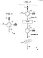
Fig. 2 is a diagram of a compact scheme for a chirped pulse amplification system using concatenated chirped fiber Bragg gratings in pulse stretching and compression. -
Fig. 3 is a diagram of a generic in-line fiber-based chirped pulse amplification system. -
Fig. 4 is an autocorrelation trace obtained with an exemplary fiber-based chirped pulse amplification system. -
Fig. 5 is a diagram of an in-line fiber-based chirped pulse amplification system with optimized polarization control. -
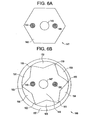
Fig. 6a . is a cross section of a polarization maintaining, few-moded, large-core double-clad fiber. -
Fig. 6b . is a generic cross section of a polarization maintaining, few-moded, large-core air-clad fiber. -
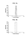
Fig. 7a is a diagram of the refractive index profile of a fiber with a co-axial, central refractive index dip. -
Fig. 7b is a diagram of the refractive index profile of an approximately step-index fiber. -
Fig. 8 is a diagram of a scheme for adaptive control of the group delay in fiber gratings in a chirped pulse amplification system. -
Fig. 9a is a diagram of a scheme for changing the temperature in adjacent sections of chirped fiber gratings for adaptive dispersion control. -
Fig. 9b is a diagram of a scheme for changing the stress in adjacent sections of chirped fiber gratings for adaptive dispersion control. -
Fig. 9c is a diagram of a scheme for changing the local refractive index in adjacent chirped fiber grating sections by the use of resistive heating. -
Fig. 10a is a diagram of a pulse train generated with a fiber grating pulse stretcher in conjunction with a bulk grating compressor. -
Fig. 10b is a diagram of a triangular pulse generated with a fiber grating pulse stretcher in conjunction with a bulk grating compressor. -
Fig. 10c is a diagram of a general arbitrary pulse form generated with a fiber grating pulse stretcher in conjunction with a bulk grating compressor. -
Fig. 11 is a diagram of the spectral reflection profile of a fiber grating pulse stretcher designed to counteract spectral gain-narrowing in a chirped pulse amplification system. The reflection profile is shown in relation to a generic spectral gain-profile of an optical amplifier. -
Fig. 12 is a diagram of an embodiment wherein a series of gratings separately stretch different portions of the input pulse spectrum. - The present invention relates to the use of nonlinearly chirped fiber gratings as pulse stretchers in ultra-compact high energy chirped pulse amplification systems. By minimizing the group delay ripple of the fiber gratings and matching their dispersion to the dispersion of bulk grating compressors, accurately dispersion matched pulse stretchers and compressors can be constructed. Very large pulse stretching ratios can thus be implemented in compact chirped pulse amplification systems. Even larger stretching ratios are possible when using concatenated fiber Bragg gratings.
- Chirped fiber Bragg gratings can be implemented as pulse stretchers for both solid-state amplifier-based and fiber amplifier-based chirped pulse amplification systems. With regards to fiber chirped pulse amplification, the obtainable pulse energies can be maximized by using polarization maintaining, large-core fiber amplifiers. For ease of alignment, and to help maintain single mode operation, fibers with approximately step-like refractive index profiles and circularly symmetric rare-earth doping profiles are preferred.
- Very high average powers can further be obtained by the implementation of double-clad fiber amplifiers. The spectral output of these amplifiers can be optimized by accurate control of the linear polarization state propagating inside the fiber amplifiers.
- Adaptive control of the group delay variations in fiber Bragg gratings can further be performed to enable the minimization of group-delay ripple-induced pulse distortions due to chirped fiber Bragg grating imperfections. Adaptive control of the chirp in fiber gratings is enabled by controlling the temperature and/or pressure (stress) inside distinct fiber grating sections. Adaptive control of the group delay variations in chirped fiber gratings can further be used to compensate for self-phase modulation in high energy amplifiers.
- The combination of fiber grating pulse stretchers and bulk grating compressors allows the generation of a variety of complex pulse shapes optimized for use in advanced micro-structuring applications.
- Finally, fiber grating pulse stretchers can be designed to counteract spectral gain-narrowing in a chirped pulse amplification system, allowing for the generation of pulses with a bandwidth comparable to the gain bandwidth of the optical amplifiers incorporated in the chirped pulse amplification system.
-
Fig. 1 represents an exemplary embodiment of the invention showing acompact pulse stretcher 100 as applicable in a generic chirped pulse amplification system. The pulse stretcher uses circulator 101 to circulate the optical signal fromcirculator port 102, via chirpedfiber Bragg gratings port 105,port 102 representing the fiber input andport 105 representing the fiber output. Pulse stretching is obtained in the two concatenated chirpedfiber Bragg gratings port 105, a large number of fiber Bragg gratings can be concatenated. By concatenating several chirped fiber gratings, very long stretched pulses can be obtained even with relatively short chirped fiber Bragg gratings. Generally, the length of chirped fiber Bragg gratings is limited to around 10 cm with current manufacturing methods, allowing for maximum stretched pulse widths of about 1 ns, independent of the input pulse width. By concatenating 4 gratings for example, stretched pulse widths up to 4 ns can be obtained, allowing an increase in pulse energy in a chirped pulse amplification system by a factor of 4. Specifically, assuming an input pulse width of 200 fs, a pulse stretching factor of up to 20,000 times can be obtained with a total fiber grating length of 40 cm in a pulse stretcher arrangement. Even larger pulse stretching factors can be implemented in principle, but are not considered practical for industrial laser systems because of the large size (> 40 - 50 cm) and cost of the required compressor grating or gratings. - However, by utilizing multiple grating stretchers, a longer pulse envelope can be generated that can be amplified to higher energies. One means to accomplish this is to have each of the stretcher gratings stretch only a portion of the spectrum of the input pulse. It is possible to coherently add the pulses back to form a single pulse, although it is difficult to maintain phase in such a case. Longer pulse envelopes from such a series of gratings can be recompressed by a series of similar compression gratings. The pulses can be incoherently added. The pulses can not be recompressed to the same degree as if a single grating is used, although this may be sufficient for many purposes.
- The use of stretched pulses with a width of, for example, 4 ns enables the amplification of these pulses to the mJ energy level in large-core (=30 µm mode diameter) Yb-doped fiber amplifiers. Such high pulse energies are very important for the application of ultrafast fiber laser sources to industrial scale machining applications.
- Though in
Fig. 1 an implementation of a pulse stretcher using a fiber optical circulator is shown, the optical circulator can be replaced with a simple polarization beam splitter and appropriate waveplates and Faraday rotators to circulate the beam between the 4 optical beam paths. Such optical assemblies are well known in the art and are not separately shown. Another alternative is the use of 3 or 4 port fiber couplers operated in reflection to concatenate several fiber Bragg gratings. The use of fiber couplers leads to an optical loss of at least 6 dB each time a fiber Bragg grating is traversed and is therefore not ideal. Another alternative is the use of a Michelson interferometer constructed from a 4 port fiber coupler; by configuring a 4 port fiber coupler as a Michelson interferometer the 6 dB loss in recirculating through the grating can be avoided. - The preferred application of the pulse stretcher as shown in
Fig. 1 is in a chirped pulse amplification system, as exemplified with theoptical arrangement 106 inFig. 2 . The pulse stretcher comprising elements 108 - 112 is configured as inFig. 1 . It is further assumed that a short optical pulse from an appropriate pulse source is injected intocirculator port 109. The pulses from thestretcher 107 are amplified inamplifier 113 and partially compressed infiber compressor 114, comprisingcirculator 115,fiber input 116, chirped fiber Bragg grating 117 andfiber output 118. Final pulse compression is performed inbulk grating compressor 119 and the output from the system is designated witharrow 120. Here the orientation of chirped fiber Bragg grating 117 inpartial compressor 118 is opposite to the orientation of the chirped fiber Bragg gratings instretcher 107, i.e. the direction of the grating chirp is reversed. If gratings 110,111 and 117 are nearly identical, grating 117 compensates for half of the pulse stretching induced bypulse stretcher 107. Hence the grating separation in bulk compressor 119 (i.e..the required optical beam paths) is also reduced by 50% (compared to a system without partial fiber compressor 117) for optimum pulse compression. Therefore the physical extent of the compressor assembly can also be minimized, which is important in any industrial application. The size ofoptical assembly 106 can further be minimized when employing positively chirped fiber stretcher gratings and negatively chirped fiber compressor gratings as well as a bulk grating compressor providing negative dispersion. Here a positively/negatively chirped fiber grating provides the smallest/largest group delay for the longest/shortest optical wavelengths inside the pulse spectrum, respectively. - Moreover, as is well known in the art, in the assembly of negative dispersion bulk gratings compressors, no lenses are required in the dispersive section of the optical beam path (i.e. the optical beam path that provides the wavelength dependent group delay), greatly simplifying its construction.
-
Bulk compressor 119 as indicated inFig. 2 is drawn only schematically, in fact,bulk compressor 119 represents two transmission gratings operated near the Littrow angle and aligned plane parallel with respect to each other. A single pass through abulk grating pair 119 as shown produces temporally compressed pulses with a spatial chirp across the output beam. However, any spatial chirp can be eliminated by simply double-passing the output beam through the bulk grating pair. For ultra-low loss gratings, passing the output beam 4 or even eight times through a bulk grating pair may be considered. Such optical arrangements are well known in the art and are not further discussed here. Equally, plane parallel reflective gratings pairs could be employed in the compressor or a compressor design based on a single transmission/reflection grating with the optical beam path being diffracted by the single grating four times. Equally, bulk optic equivalents of chirped fiber Bragg gratings as discussed inA. Galvanauskas et al, US Patent No. 5,499,134 can also be implemented as pulse compressors. Such assemblies are also well known in the art and are not further discussed here. - Although, the present example refers to a dual fiber grating stretcher and a single fiber grating partial compressor, any number N of fiber gratings can be used in the stretcher. The number of fiber gratings in the compressor can then be selected between 1 to N, where the residual uncompensated group delay is compensated with a bulk grating compressor. The
amplifier 113 can comprise a fiber, semiconductor or bulk laser amplifier. Alternatively, nonlinear amplifiers such as a Raman or parametric amplifers can also be implemented, where implementations in both waveguide (fiber) or bulk optical form are acceptable. In conjunction with bulk amplifiers, it is advantageous to implement multiple passes through the amplifier medium or to implement a regenerative optical amplifier. Such optical systems are well known in the art andamplifier 113 is representative of any such bulk optical amplification system. A plurality of amplifiers can be used. Either the same or different type. - The system shown in
Fig. 2 can be further implemented in a compact fiber optic pulse delivery system. Fiber delivery systems have previously been discussed inUS patents 5,862,287 and6,249,630 to Stock et al . and later byKafka et al. in US patents 6,236,779 and6,389,198 . In the most basic implementation,compressor 119 is omitted and the dispersion of the fiber grating stretcher/compressor assembly is adjusted to obtain optimally compressed pulses atoutput 118. Alternatively, the dispersion inside the fiber grating stretcher/compressor assembly can be adjusted to obtain optimally compressed pulses after propagation of the pulses fromoutput 118 through a coupled functional end-use system having an additional optical assembly, such as an optical lens assembly or simply a piece of solid glass, in place of or in addition tocompressor 119. Thus, the pulses may be "preconditioned" so as to be delivered in an optimal state after passing through the subsequent optics (of known dispersion characteristics) of an end-use apparatus. Moreover, the output pulses designated byarrow 120 can be coupled into a low-nonlinearity holy or photonic bandgap pulse delivery fibers; providing for guided propagation via holes surrounding a fiber core or even providing for guided propagation predominantly inside an air-hole as well known in the state of the art. The fiber gratings can thus be implemented to compensate for the dispersion of these fibers to produce the shortest possible pulse at the end of these delivery fibers. Note that the work by Kafka did not provide for any provision to compensate for the dispersion of the photonic bandgap delivery fiber. The holy or photonic bandgap fiber can also be engineered to provide the correct dispersion to be used as pulse compressor or partial pulse compressor for a stretched pulse. Such pulse compressor and partial pulse compressor function of the holy or photonic bandgap fibers can be used in combination with the power delivery function of the same fibers. - To enable re-compression of the stretched pulses obtained from a chirped fiber grating stretcher in a bulk grating compressor, the group delay as a function of wavelength in the chirped fiber Bragg grating assembly has to be matched to the group delay as a function of wavelength generated in the bulk grating compressor. This is performed by balancing the spectral phase of the stretcher/compressor assembly. Generally, the group delay as a function of optical frequency produced by a highly dispersive bulk grating compressor is nonlinear, hence the chirped fiber Bragg grating stretcher needs to be designed with the opposite nonlinear group delay as a function of optical frequency. The nonlinear group delay can also simply be referred to as nonlinear chirp.
- Generally, it is very difficult to match the nonlinear chirp produced by the stretcher/compressor assembly perfectly. Due to phase errors in the fiber grating stretcher, in general the fiber grating stretcher will exhibit periodic variations of the group delay from the design curve. The group delay variations produced in a fiber grating can be measured using standard techniques well known in the art. The group delay mismatch between stretcher and compressor can then be measured or calculated (generally, it is sufficient to calculate the group delay produced by a bulk grating compressor; a separate measurement is not necessary) and the results can be fed back to the fabrication process of the fiber grating, i.e. the dc or the ac component in the writing procedure of a fiber Bragg grating can be appropriately modified to reduce the group delay mismatch between fiber grating stretcher and bulk compressor. Through an iterative process very low group delay mismatch between stretcher and compressor can be obtained.
- Note that iterative methods to minimize the group delay of chirped fiber gratings have been demonstrated (M. Sumetsky et al., 'Reduction of chirped fiber grating group delay ripple penalty through UV post processing, Conference on Optical Communications, OFC, Atlanta (2003), paper PD28), though to the author's knowledge the iterative method of group delay ripple reduction has not previously been suggested in the construction of high energy chirped pulse amplification systems. As is evident in the article by Sumetsky et al., without iterative group delay ripple reduction, a group delay ripple as large as ±10 ps is generated even in high-quality chirped fiber Bragg gratings. With iterative group delay ripple reduction, the group delay can be reduced to ±2 ps and even smaller values are possible. For pulse compression down to below 1 ps the control of group delay ripple is becoming increasingly significant, in eliminating an unwanted pulse pedestal, which can be detrimental in advanced material processing applications.
- Referring now to
Fig. 3 ,optical assembly 121 represents an example of a fiber-based chirped pulse amplification system. Short optical pulses from preferably a short pulse fiber oscillator 122 (as for example described inUS Patents 5,689,519 ;5,450,427 ;5,627,848 ; and6,072,811 all to Fermann et al .) are injected intocirculator 123 and stretched in nonlinearly chirped fiber Bragg grating 124. The stretched pulses are subsequently amplified infiber amplifier 125.Fiber amplifier 125 is preferably based on a double-clad fiber pumped with a high power multi-mode diode laser, though single-clad fiber amplifiers pumped with high power single mode diode lasers can also be implemented. End-pumped or side-pumped amplifier designs can be implemented; as discussed for double-clad fibers inUS Patent 5,854,865 to L. Goldberg ;US Patent 4,815,079 to E. Snitzer et al. ; andUS Patent 5,864,644 to DiGiovanni . Such pumping arrangements are well known in the art and not further discussed here.Collimation lens 126 collimates the amplified pulses emerging from the amplifier and a single or double pass throughbulk grating compressor 127 provides compression down to the bandwidth limit. The direction of the output pulses is exemplified witharrow 128. - In a system demonstration, pulses with a full width half maximum (FWHM) width of 350 fs from a passively modelocked Er fiber oscillator operating at a repetition rate of 50 MHz were stretched in a 10 cm long nonlinearly chirped fiber Bragg grating to a width of 700 ps. The nonlinearly chirped fiber grating was designed (e.g., by the iterative method) to provide the same dispersion as the bulk grating compressor; the bulk grating here having a groove spacing of 1200 lines/mm and operated at the Littrow angle. The maximum group delay variations (or group delay ripple) from the designed group delay in the chirped fiber Bragg grating were measured at ±<2 ps. The oscillator pulse energy was 100 pJ. After amplification by a factor of 10, the pulses were recompressed in the bulk grating compressor. The recompressed pulses had a FWHM width of ≈700 fs sitting on an additional pedestal with a FWHM width of 3 ps, containing about 2% of the pulse energy. Hence a compression ratio of up to 1000 was obtainable with the present arrangement, limited only by the bandwidth of the amplifier. An autocorrelation of the compressed pulses with a 2% pedestal energy content is shown in
Fig. 4 . - Though the amplified pulse energy in the present system was only 1 nJ, by reducing the repetition rate of the seed source, and the incorporation of additional fiber amplifier stages, much higher pulse energies can be generated. It is therefore instructive to calculate the practical energy limits of the present chirped pulse amplification system. The maximum obtainable pulse energy E can be expressed as

where Φnlmax is the maximum tolerable nonlinear phase delay (as induced by self-phase modulation) inside the fiber amplifier, τst is the FWHM width of the stretched pulses, γeff is the effective nonlinearity parameter of the fiber and Leff is the effective length of the final fiber power amplifier. For a large mode fiber with a mode diameter of 30 µm (which is generally obtainable with diffraction limited multi-mode fibers as discussed inUS Patent No. 5,818,630 ) γeff can be calculated as γeff = 2×10⁻⁴ /mW at a wavelength of 1550 nm. Highly Er doped silica fibers allow an effective amplifier length shorter than 0.5 m. Moreover, for waveguide amplifiers Φnlmax ≈10 can be tolerated without significant pulse distortions. - Hence, for a stretched pulse width of τst = 4 ns, output sub-picosecond pulses with a pulse energy larger than 400 µJ can be safely generated in a large mode fiber with this system.
- Regarding size constraints, the bulk compressor could fit into a box with a length of 2 m using 4 passes through a single bulk grating. Using additional optical folding, a compressor size of 1 m could be obtained. Considering that such laser systems would be used in heavy industrial machining (or other applications), located in a large factory hall, a box length of 1 m poses no significant obstacles.
- Referring now to
Fig. 5 , an alternative basic fiber-based chirped pulse amplification system 129 based on predominantly polarization maintaining (PM) fibers is illustrated. System 129 comprises an integrated oscillator/fiber gratingpulse stretcher assembly 130, with a PM fiber pig-tail output 131. A polarizer 132 (fiber or bulk) is inserted beforePM fiber pre-amplifier 133. Asecond polarizer 134 is inserted beforepulse picker 135, which is used to down-count the repetition rate set by the oscillator by a selectable factor, thus providing seed pulses with a reduced repetition rate to the rest of the amplifier system. Anotherpolarizer 136 is inserted before PMfiber power amplifier 137.Lens 138 is used to produce a collimated output frompower amplifier 137. A single or double pass (or quadruple pass) throughbulk compressor 139 provides final pulse compression and the direction of the output pulses is designated witharrow 140. - PM fibers are preferably constructed using fibers with an internal birefringence Δn, where Δn > 5×10⁻⁵ and preferably Δn > 1×10⁻⁴. A fiber with a birefringence Δn = 1×10⁻⁴ produces a polarization beat length lb of lb = λ/Δn = 10 mm at a wavelength of 1050 nm. When launching a linear polarization state into a birefringence axis of such a fiber, the linear polarization state can be preserved over lengths of several meters with only minimal cross coupling to the orthogonal polarization axis. The leakage to the orthogonal polarization axis can be as small as -40 dB, i.e. the cross coupling to the orthogonal polarization state can be as small as 0.01%.
- Assuming now that a linearly polarized pulse is launched with an angular rotational misalignment α with respect to a polarization axis of the fiber, this polarization axis is excited with a relative intensity of cos2 α and the orthogonal fiber polarization axis is excited with a relative intensity of sin2α.
- Due to group velocity walk off in the PM fiber, at the PM fiber output, two time delayed pulses propagating in the two orthogonal polarization axes are generated with the main pulse having a relative intensity of ≈1 and the leakage pulse having a relative intensity of sin2α. The time delay between the pulses is given by τd ≈ LΔn/c, where L is the fiber length and c is the velocity of light. For a 3 m fiber length and Δn = 1×10⁻⁴, the time delay between the pulses is calculated as τd =1 ps. When a second PM fiber is spliced to the first fiber with an angular misalignment of β, the leakage pulse couples to the main pulse generating a time delayed pulse in the same polarization state as the main pulse with a relative intensity of sin2 α sin2 β. Assuming α = β the leakage pulse has a relative intensity of sin4α.
- The leakage pulse in turn provides a modulation on the spectral output of the system with a frequency f = 1/τd. For a time delay of 1 ps, the modulation frequency corresponds to a sinusoidal perturbation of the optical spectrum of 8 nm. The depth of the spectral perturbation corresponds to ≈ 4sin2 α; i.e. for a leakage pulse with a relative intensity of 1%, the corresponding relative modulation of the optical spectrum is ≈ 40%. The spectral modulation depth is typically further amplified in high gain amplifier systems and can degrade the obtainable pulse quality. When concatenating several sections of polarization maintaining fiber, very large spectral modulations can be obtained in high gain fiber amplifier systems leading to substantial degradation of pulse quality, especially in the presence of self-phase modulation.
- To limit the polarization leakage induced spectral modulations in in-line fiber chirped pulse amplification systems it is therefore preferable to minimize the number of polarization maintaining fiber sections and to insert high extinction polarizers or fiber polarizers between sections of polarization maintaining fiber as shown in
Fig. 5 . These polarizers limit the formation of time delayed leakage pulses propagating in the same polarization direction as the main pulse. If the required pulse quality is not very critical, however, the in-line polarizers can be omitted and a very low-cost and simple design can be obtained. - Referring now to
Figs. 6a and 6b , two alternative embodiments of PM high power fiber amplifiers are shown.Fig. 6a shows the cross section of a double cladlarge mode fiber 141. The fiber comprises afirst cladding 142, a rare-earth-dopedcore 143 with a diameter > 15 µm andstress producing regions cladding 142. The second cladding is not separately shown. Additional polymer coating can be applied to the outside of the second cladding. A variety of fiber designs and cladding shapes for PM high power fiber amplifiers are discussed inUS Patent Application 09/809,248 to Fermann et al - A limitation with the fiber design from
Fig. 6a is the limited numerical aperture of the cladding, which limits the amount of power that can be coupled into the fiber. A higher cladding numerical aperture can be obtained with an air-cladfiber 146 as shown inFig. 6b . Here thefiber core 147 has preferably a diameter of more than 15 µm.Core 147 is surrounded byfirst cladding 148 containingstress producing regions first cladding 148 is in turn surrounded by a second cladding, comprising air-holes 151-156. The first cladding is further attached to athird cladding 157 at bridge points 158- 163. To maximize the numerical aperture of the air cladding 151-156, the bridge points 158-163 betweenfirst cladding 148 andthird cladding 157 are made as small as possible. For additional protectionthird cladding 157 can further be surrounded by a protective coating; alternatively a gold coating (or other metal coating) can be deposited onthird cladding 157 to enable soldering of the fiber to a heat sink. Any coatings outsidethird cladding 157 are not separately shown. - Though a star-shaped air-cladding is shown in
Fig. 6b , other forms such as ring segments separated by glass bridges between the first and third cladding are equally possible. Alternatively, closely spaced air-holes located between the first and third cladding can also be implemented. Various cladding shapes for air-clad fibers are well known in the art and are not further discussed here. - The numerical aperture of the cladding of a fiber according to
Fig 6b can be about 50% higher than the numerical aperture of the cladding of a fiber similar toFig. 6a . Hence for diode pump sources with a given brightness B, more than twice as much power can be coupled into air-clad fibers similar to the type shown inFig. 6b compared to fibers similar to the design shown inFig. 6a . - Referring now to
Figs. 7 , some design considerations specific to the large-core MM fiber lasers typically used in the invention will be discussed. In the design of diffraction-limited large-core multi-mode fiber lasers, it is advantageous to use fibers with an approximately step-like refractive index profile as pointed out inUS Patent. 5,818,630 . In contrast, rare-earth-doped fibers made by modified chemical vapor deposition (MCVD) tend to have a co-axial central dip in the refractive index profile as shown inFig. 7a . InFig. 7a the values for the refractive index serve only as an example and the exact refractive index depends on the fiber's glass composition. Note that inFig. 7a only the refractive index for the core region and the immediately adjacent first cladding region are shown. - For fibers as shown in
Fig. 7a , the gain may be higher for higher order modes compared to the gain for the fundamental core mode, especially if the rare-earth-ion distribution follows the refractive index profile, at least approximately. Moreover, a dip in the refractive index profile may produce a ring mode as the lowest order mode for the fiber core with reduced focussability compared to a mode with a gaussian intensity distribution. - In contrast, a fiber with a step-like refractive index distribution as shown in
Fig. 7b is preferable. In practice, a step-like refractive index distribution can be generated by MCVD by increasing the doping level of the index raising dopants in the central core region before preform collapse. In the presence of dopant outgassing during fiber preform collapse a final refractive index profile as shown inFig. 7b can be obtained. Alternatively, other fiber manufacturing methods can be implemented where the susceptibility to the generation of a central dip in the refractive index profile is less prevalent; for example outside vapor deposition (OVD) or vapor axial deposition (VAD) may be implemented for this purpose. -
Fig. 8 illustrates how chirped fiber Bragg gratings can be implemented to adaptively compensate any residual dispersion profile mismatch between a fiber grating stretcher and a bulk grating compressor, greatly improving the fabrication yield of chirped pulse amplification systems. Adaptive pulse compressors are known in the art, but because conventional adaptive compressor systems are based on complex and expensive bulk optics arrangements, they are generally not used in commercial laser systems. In contrast, an integrated and miniaturized fiber-based adaptive pulse stretcher has a great market potential. -
Optical assembly 164 comprises anultrafast oscillator 165 emitting short optical pulses. These pulses are injected intooptical circulator element 166.Element 167 represents an optical amplifier andelement 168 represents a bulk compressor; the output from the system is represented witharrow 169.Circulator 166 circulates the oscillator pulses intoadaptive pulse stretcher 170.Adaptive pulse stretcher 170 comprises a chirped fiber Bragg grating 171 with an array of selectively electronically addressable segments 172- 175. While four array elements are illustrated by way of example, any number of segments can be used. Because of the high quality of nonlinearly chirped fiber Bragg gratings, only a limited number of individually addressable fiber Bragg grating sections is required. For a 10 cm long grating, around 100-200 individually addressable fiber grating sections are sufficient. -
Beam splitter 176 deflects a small fraction of theoptical output beam 169 generating anoptical beam 177. A frequency-doubler assembly 178 is then used to provide a feedback signal viaelectrical control line 179 to adaptively control the fiber array segments to maximize the doubled output power using general numerical algorithms. - Instead of
frequency doubler 178, other nonlinear pulse characterization devices could be used to provide a feedback signal to the adaptive pulse stretcher. Such pulse characterization devices can comprise auto-correlators or frequency-resolved optical gating devices, just to name two examples. Not only the peak power, but also the pulse quality of the compressed pulses can thus be directly measured and optimized. - Adaptive control of the chirp inside fiber Bragg grating 171 is obtained by independently modifying the refractive index in each of the separate fiber sections 172 -175. Mechanisms for index modification will be described in
Figs. 9 . Considering that the amount of chirp control possible with an adaptivefiber pulse stretcher 170 is relatively small, however, one skilled in the art will recognize that the dispersion profile of the fiber Bragg grating pulse stretcher needs to be as closely matched to the dispersion profile of thebulk grating compressor 168 as possible initially. Residual ripple in the group delay produced by the chirped fiber Bragg grating or any small mismatch between the dispersion profile of the stretcher/compressor assembly can then be adaptively corrected, allowing for the compression of stretched pulses down to near the bandwidth limit. -
Figs. 9a-c demonstrate various methods for modifying the refractive index in separate, individually addressable fiber grating sections. InFig. 9a adaptive pulse stretcher 180 contains fiber grating 181 and allows modification of the refractive index of an array of fiber sections via thermal control. For example fiber Bragg grating 181 can be attached to an array of thermo-electric heater/cooler elements 182 -185, which modify the refractive index profile according to the temperature profile applied by heater/cooling elements 182-185. -
Fig.9b illustrates an adaptivepulse stretcher system 186 containing fiber grating 187. Here piezoelectric elements 188-191 are used to produce controllable amounts of strain in adjacent fiber sections by pressing fiber grating 187 againstflat plane 192. Elements 188-191 are attached to holders 193 -196 to enable packaging of the optical assembly. -
Fig. 9c displays yet another alternative embodiment for an adaptive pulse stretcher using resistive heating of sections of a fiber grating.Adaptive pulse stretcher 197 comprises fiber grating 198 with a number of metal coated sections 199-202. For example a combination of Ni and Au coating is appropriate. The electrically isolated sections can be manufactured by metal coating the whole grating length and then selectively etching away narrow isolating sections 210. The coating is further attached tocommon ground 203. A circuit board-like mask 204 with electrically conducting, though mutually electrically isolated, sections 205-208 is then positioned on top of the metal coated fiber grating sections and arranged such that individually controllable currents can be applied. In the present arrangement the current flows betweensections 199/205, 200/206, 201/207 and 202/208 respectively. Resistive heating of the metal coating thus heats the individual fiber grating sections, producing proportional refractive index changes in the fiber grating sections as required for adaptive control. - By adaptively controlling the chirp in fiber grating pulse stretchers, large amounts of self-phase modulation can also be compensated. Self-phase modulation generally produces a nonlinear chirp in stretched and amplified pulses which is, to first order, additive to the pulse chirp and not compressible with a conventional stretcher/compressor assembly. However, because the chirp induced by self-phase modulation is additive to first order, it can be pre-compensated in an adaptive pulse stretcher. Indeed, since the amount of induced self-phase modulation depends on the amplified stretched pulse shape, the required fiber grating modification can be estimated from a measurement of the stretched pulse shape and a static (non-adaptive) fiber grating stretcher for self-phase modulation compensation can also be implemented.
- For some machining applications, complex pulse shapes or pulse trains may be required to achieve optimum performance. Chirped fiber Bragg grating stretchers in conjunction with bulk grating compressors can also be implemented as general pulse shaping devices to produce such complex pulse shapes. In this case, fiber Bragg grating designs can be obtained directly from the required output and input pulse shapes using inverse scattering algorithms well known in the state of the art. Fiber Bragg gratings usually have complex continuously varying amplitude and phase structures with discrete phase jumps at various locations along the grating. This type of fiber Bragg grating can usually be written by a continuous write and translate system. For example, as shown in
Fig. 10a , by appropriately controlling the phase and the chirp of a fiber Bragg grating, a double-pulse can be generated after compression with a bulk grating compressor. With appropriate fiber Bragg grating designs, the shape of each sub-pulse can be tailored as well as the delay between two pulses. With ten centimeter long fiber Bragg gratings, ns pulse separations can be achieved. This can be further increased if longer fiber Bragg gratings are used. Equally, well defined pulse trains can be generated to be used in micro-machining. Similarly, inFig. 10b a triangular pulse shape is obtainable from a pulse shaping fiber Bragg grating. Generally, arbitrarily selectable pulse shapes, as shown inFig. 10c , can be generated from pulse shaping fiber Bragg gratings. If high peak pulse powers are not required, a bulk grating compressor does not need to be implemented and appropriately shaped pulses can be extracted directly after reflection from a fiber Bragg grating. - In short, the above disclosure describes optimized fiber Bragg grating pulse stretchers allowing for 1) precise dispersion control, 2) compensation of self-phase modulation and 3) the generation of optimum pulse shapes for micro-machining and other end uses via a chirped pulse amplification system.
- In ultrafast optics applications, the generation of the shortest possible pulses from a chirped pulse amplification system is equally of prime interest. The obtainable pulse widths from chirped pulse amplification systems is limited by gain-narrowing in the amplifiers. Gain narrowing can be counterbalanced by fiber Bragg grating pulse stretchers that exhibit a reduction in reflectivity at the peak of the gain in the amplifier chain as implemented in a generic chirped pulse amplification system. This is further illustrated in
Fig. 11 . The combination of gain and reflectivity profiles as exemplified inFig. 11 maximizes the spectral bandwidth of the amplified pulses minimizing the amplified pulse bandwidth. Moreover, whereas inFig. 11 a relatively simple gain profile is shown, gain narrowing in more complex gain profiles can also be counterbalanced by appropriately designed pulse stretching fiber Bragg gratings. The optimum reflectivity profile is then determined by the largest amplified spectral bandwidth, for a given tolerable level of amplifier noise, i.e. any modulation of the reflection profile of the fiber Bragg grating pulse stretchers produces a reduction in the injected seed pulse energy into the amplifier chain. In practice a seed pulse energy reduction by more than 90 -99% cannot be tolerated, because of the onset of significant amplifier noise in the output of the amplifier. - A further embodiment shown in
Fig. 12 focuses on increasing the possible energy and average power from ultrafast fiber lasers. A longer pulse envelope can be obtained by utilizing a series of chirped gratings that reflect at different wavelengths. After amplification a similar series of gratings can be placed to recombine/compress the pulses. As shown inFig. 12 , pulses from a femtosecond pulse source are passed through an acousto-optic modulator, a polarized beam-splitter and a Faraday rotator, then supplied to a series of chirped fiber stretcher gratings which operate on different portions of the input pulse spectrum. The spacings between the stretcher gratings can be l1, l2, l3 .... In order to reconstruct the pulses after amplification in, e.g., a Yb amplifier, the spacings between a series of complementary bulk glass Bragg grating compressors are set to nl1, nl2, nl3, ..., where n is the refractive index of the fiber between the stretcher fiber gratings, assuming that the bulk Bragg compression gratings are separated by air. The reconstructed pulse is output via a second beam splitter. As previously mentioned, the reconstructed pulse is generally the result of incoherent addition of the separately amplified spectral components of the input pulse. - If the spacings between the compression and stretcher gratings are not equalized as described above, then multiple pulses will appear at the output. This can be beneficial for applications such as micromachining. By varying the stretching and compression ratios pulses with different pulse widths can be combined. A single broadband compression grating can be used if multiple pulses are desired.
- This technique can also be used to increase the repetition rate. To increase the repetition rate by n times, n gratings would be used. The separation of these gratings would be equal to the time period between pulses T divided by n times the speed of light.
- In this disclosure there are shown and described only the preferred embodiments of the invention and but a few examples of its versatility. It is to be understood that the invention is capable of use in various other combinations and environments and is capable of changes or modifications within the scope of the inventive concept as expressed herein.
- There are several aspects of the invention which, at the top level, may be considered. At one broad level, the invention can be characterized as a chirped pulse amplification system including a nonlinearly chirped fiber Bragg grating pulse stretcher system, the fiber Bragg grating pulse stretcher system producing stretched pulses longer than 300ps; at least one amplifier following the stretcher system, and a pulse compressor for compressing the stretched pulses by more than a factor of 50.
- At another broad level, the invention can be characterized as a chirped pulse amplification system including a nonlinearly chirped fiber Bragg grating pulse stretcher system, the fiber Bragg grating pulse stretcher system producing stretched pulses longer than 1 ns; at least one amplifier following the stretcher system, and a pulse compressor for compressing the stretched pulses by more than a factor of 150.
- Similarly, the invention can also be characterized as a chirped pulse amplification system including a nonlinearly chirped fiber Bragg grating pulse stretcher system, the fiber Bragg grating pulse stretcher system producing stretched pulses longer than 100 ps; at least one amplifier following the stretcher system, and a pulse compressor for compressing the stretched pulses by more than a factor of 50. Herein, the amplifier can be one of a bulk amplifier, a fiber amplifier, a diode laser amplifier, a parametric amplifier, a Raman amplifier or a combination thereof. Further, the fiber Bragg grating pulse stretcher system includes plural concatenated fiber Bragg grating stretchers, and the pulse compressor includes at least one fiber Bragg grating compressor and a bulk grating compressor. The fiber amplifier may be pumped, for example core pumped, by an additional fiber laser or amplifier. The amplifier may be one of an Yb-or Nd fiber amplifier, and in a specific example, the amplifier is an Yb fiber amplifier core-pumped with a Nd-fiber laser or amplifier. An adaptively controlled pulse shaper may be located up-stream of the amplifier, in order to pre-compensate for self-phase modulation in the amplifier.
- Optimally compressed pulses are obtained at a target downstream from the pulse compressor, where the optical beam-path between the pulse compressor and the target further contains additional optical elements other than air, such as optical beam delivery fibers, inclusive of single-mode fiber, a multi-mode fiber operated with a single-mode output, a holy fiber, a photonic crystal fiber, and a fiber with a guiding air-hole core.
- The invention may also be broadly characterized as a chirped pulse amplification system, including a seed pulse source producing short optical pulses with a certain spectral bandwidth; a chirped fiber Bragg grating stretcher, the fiber Bragg grating stretcher exhibiting a group delay ripple of less than 10 ps within the spectral bandwidth of the seed pulse source; an amplifier following the stretcher; and a compressor for recompressing the stretched pulses.
- Similarly, in another aspect of the invention, an optical combination includes a seed pulse source producing optical pulses with a certain spectral bandwidth; a chirped fiber Bragg grating stretcher system, the fiber Bragg grating stretcher system exhibiting a group delay ripple of less than 10 ps within the spectral bandwidth of the seed pulse source; and an amplifier following the stretcher.
- The invention may also be characterized as a method, e.g., a method for designing the dispersion profile of a chirped fiber Bragg grating stretcher to match the dispersion profile of a bulk grating compressor; including measuring or calculating the dispersion profile of the bulk grating compressor; producing the chirped fiber Bragg grating stretcher; subsequently measuring group delay variations produced by the chirped fiber Bragg grating stretcher as compared to the bulk grating compressor; and iteratively modifying UV-light exposure of the chirped fiber Bragg grating to minimize the group delay variations inside the chirped fiber Bragg grating. Similarly, the invention encompasses a method for designing the dispersion profile of a chirped fiber Bragg grating stretcher; including producing the chirped fiber Bragg grating stretcher; subsequently measuring group delay variations produced by the chirped fiber Bragg grating stretcher as compared to a designed dispersion profile; and iteratively modifying UV-light exposure of the chirped fiber Bragg grating to minimize the group delay variations inside the chirped fiber Bragg grating. The invention also encompasses a method for designing the dispersion profile of a chirped fiber Bragg grating stretcher; including producing the chirped fiber Bragg grating stretcher; subsequently measuring group delay variations produced by the chirped fiber Bragg grating stretcher as compared to a designed dispersion profile; iteratively modifying UV-light exposure of the chirped fiber Bragg grating to minimize the group delay variations inside the chirped fiber Bragg grating, and adaptively modifying the dispersion profile of the chirped fiber Bragg grating in use by controllably modifying a refractive index of at least one selectable portion thereof.
- In another aspect, the invention may be characterized broadly as a chirped pulse amplification system, including a seed pulse source producing short optical pulses; a stretcher for stretching the pulses; and a plurality of concatenated sections of predominantly polarization maintaining fiber, at least one of which is also an amplifier.
- In this aspect, there is at least one polarizer between sections of predominantly polarization maintaining fiber, and at least one of the predominately polarization maintaining fibers is an air-clad fiber. Polarization maintaining operation of the air-clad fiber is obtained by the incorporation of stress producing regions into the air-clad fiber, and at least one of the predominately polarization maintaining fibers is a double or n-tuple clad fiber.
- In another aspect, the invention can be characterized as a chirped pulse amplification system including at least one nonlinearly chirped fiber Bragg grating pulse stretcher producing stretched pulses; at least one amplifier following the stretcher, and a pulse compressor for compressing the stretched pulses, the compressed pulses having an energy >100 nJ. In this aspect, the compressor includes at least one chirped fiber Bragg grating and a bulk grating, and/or a holy or photonic bandgap fiber. In the case of the holy or photonic bandgap fiber, it may be engineered to perform complete pulse compression or partial pulse compression, and also acts as power delivery fiber.
- In another broad aspect, the invention may be characterized as a chirped pulse amplification system including a short pulse seed source, a fiber grating pulse stretcher, an adaptive pulse shaper, at least one amplifer and a pulse compressor. In this aspect, the amplifier is one of a fiber, Raman, parametric, solid-state or diode amplifier. The adaptive pulse shaper is an adaptive fiber grating based pulse shaper, and the fiber grating pulse stretcher and the adaptive pulse shaper may be combined into one integrated fiber grating pulse shaping device.
- Herein, adaptive pulse shaping in the fiber grating pulse shaper is enabled via modifying a refractive index of at least one selectable portion of the grating pulse shaper by controlling a temperature of the selectable portion, or by modifying a refractive index of at least one selectable portion of the grating pulse shaper by controlling an internal stress within the selectable portion. The number of the selectable portions is in a range between 4 and 4000.
- In another aspect, the invention may be characterized as a pulse amplification system including a nonlinearly chirped fiber Bragg grating pulse stretcher, the fiber Bragg grating pulse stretcher producing stretched pulses longer than 1 ns; at least one amplifier following the stretcher, and a pulse compressor for compressing the stretched pulses by more than a factor of 50, the pulses having an energy of >1 µJ. (1 micro J)
- In another aspect, the invention may be characterized as a pulse amplification system including a nonlinearly chirped fiber Bragg grating pulse stretcher, at least one fiber amplifier following the stretcher and having a substantially step index profile, and a pulse compressor for compressing the stretched pulses.
- An additional method characterization of the invention is that of adaptively modifying the dispersion profile of a chirped fiber Bragg grating, including modifying a refractive index of at least one selectable portion of the grating in order to pre-compensate for self-phase modulation in one or more following amplifier stages.
- An additional method characterization of the invention is that of pre-compensating for self-phase modulation induced in one or more optical amplifier stages, including statically or adaptively modifying the dispersion profile of a chirped fiber Bragg grating optically preceding the one or more amplifier stages.
- A further aspect of the invention may be characterized as a pulse amplification system including a fiber Bragg grating pulse stretcher, the fiber Bragg grating pulse stretcher producing stretched pulses or pulse trains with a prescribed, but freely selectable amplitude and phase profile, at least one amplifier following the stretcher, and a pulse compressor for compressing the stretched pulses, thereby producing output pulses or output pulse trains with a freely selectable amplitude profile. Herein, the freely selectable amplitude profile is produced at a target material, the optical beam path between the bulk compressor and the target material further contains optical material other than air, including either of bulk optical materials and or optical delivery fibers. The output pulse or output pulse trains can be used for micro-structuring or micro-machining of a target material, the amplitude profile is optimized for the micro-structuring properties of the target material. Further or alternately, the freely selectable amplitude profile generated by the pulse stretcher is used to counteract gain-narrowing in the at least one amplifier down-stream from the pulse stretcher, such that the amplified pulse width after compression in the pulse compressor is minimized.
- In another aspect, the invention is a chirped pulse amplification system, including a fiber Bragg grating pulse stretcher system including a plurality of fiber Bragg gratings, each of which is designed to stretch a separate spectral component of an input pulse; at least one amplifier following the stretcher system, and a pulse compressor system for compressing and reconstructing the stretched pulses by incoherent addition. Herein, the compressor system includes a series of bulk compressors spaced so as to temporally reconstruct the input pulse, or one or more bulk compressors spaced so as to output temporally separated portions of the input pulse.
- It should be noted and understood that all publications, patents and patent applications mentioned in this specification are indicative of the level of skill in the art to which the invention pertains. All publications, patents and patent applications are herein incorporated by reference to the same extent as if each individual publication, patent or patent application was specifically and individually indicated to be incorporated by reference in its entirety.
- Examples of the invention forming part of the description:
- 1. A chirped pulse amplification system comprising, a nonlinearly chirped fiber Bragg grating pulse stretcher system, said fiber Bragg grating pulse stretcher system producing stretched pulses longer than 300ps; at least one amplifier following said stretcher system, and a pulse compressor for compressing said stretched pulses by more than a factor of 50.
- 2. A chirped pulse amplification system comprising, a nonlinearly chirped fiber Bragg grating pulse stretcher system, said fiber Bragg grating pulse stretcher system producing stretched pulses longer than 1 ns ; at least one amplifier following said stretcher system, and a pulse compressor for compressing said stretched pulses by more than a factor of 150.
- 3. A chirped pulse amplification system comprising, a nonlinearly chirped fiber Bragg grating pulse stretcher system, said fiber Bragg grating pulse stretcher system producing stretched pulses longer than 100 ps; at least one amplifier following said stretcher system, and a pulse compressor for compressing said stretched pulses by more than a factor of 50.
- 4. A chirped pulse amplification system according to example 3, wherein said amplifier comprises one of a bulk amplifier, a fiber amplifier, a diode laser amplifier, a parametric amplifier, a Raman amplifier or a combination thereof.
- 5. A chirped pulse amplification system as in example 3, wherein said fiber Bragg grating pulse stretcher system includes plural concatenated fiber Bragg grating stretchers.
- 6. A chirped pulse amplification system as in example 3, wherein said pulse compressor comprises at least one fiber Bragg grating compressor and a bulk grating compressor.
- 7. A chirped pulse amplification system as in example 3, wherein optimally compressed pulses are obtained at a target downstream from said pulse compressor, where the optical beam-path between said pulse compressor and said target further contains additional optical elements other than air.
- 8. A chirped pulse amplification system as in example 7, wherein said additional optical elements comprise optical beam delivery fibers.
- 9. A chirped pulse amplification system as in example 8, wherein said delivery fiber comprises one of a single-mode fiber, a multi-mode fiber operated with a single-mode output, a holy fiber, a photonic crystal fiber, and a fiber with a guiding air-hole core.
- 10. A chirped pulse amplification system, comprising; a seed pulse source producing short optical pulses with a certain spectral bandwidth; a chirped fiber Bragg grating stretcher, said fiber Bragg grating stretcher exhibiting a group delay ripple of less than 10 ps within the spectral bandwidth of said seed pulse source; an amplifier following said stretcher; and a compressor for recompressing said stretched pulses.
- 11. An optical combination, comprising; a seed pulse source producing optical pulses with a certain spectral bandwidth; a chirped fiber Bragg grating stretcher system, said fiber Bragg grating stretcher system exhibiting a group delay ripple of less than 10 ps within the spectral bandwidth of said seed pulse source; and an amplifier following said stretcher.
- 12. A method for designing the dispersion profile of a chirped fiber Bragg grating stretcher to match the dispersion profile of a bulk grating compressor; comprising measuring or calculating the dispersion, profile of the bulk grating compressor; producing the chirped fiber Bragg grating stretcher; subsequently
measuring group delay variations produced by the chirped fiber Bragg grating stretcher as compared to the bulk grating compressor; and iteratively modifying UV-light exposure of the chirped fiber Bragg grating to minimize the group delay variations inside the chirped fiber Bragg grating. - 13. A method for designing the dispersion profile of a chirped fiber Bragg grating stretcher; comprising, producing the chirped fiber Bragg grating stretcher; subsequently measuring group delay variations produced by the chirped fiber Bragg grating stretcher as compared to a designed dispersion profile; and iteratively modifying UV-light exposure of the chirped fiber Bragg grating to minimize the group delay variations inside the chirped fiber Bragg grating.
- 14. A method for designing the dispersion profile of a chirped fiber Bragg grating stretcher; comprising, producing the chirped fiber Bragg grating stretcher; subsequently measuring group delay variations produced by the chirped fiber Bragg grating stretcher as compared to a designed dispersion profile; iteratively modifying UV-light exposure of the chirped fiber Bragg grating to minimize the group delay variations inside the chirped fiber Bragg grating, and adaptively modifying the dispersion profile of the chirped fiber Bragg grating in use by controllably modifying a refractive index of at least one selectable portion thereof.
- 15. A chirped pulse amplification system, comprising; a seed pulse source producing short optical pulses; a stretcher for stretching said pulses; and a plurality of concatenated sections of predominantly polarization maintaining fiber, at least one of which is also an amplifier.
- 16. A chirped pulse amplification system as claimed in example 15, further comprising; at least one polarizer between sections of predominantly polarization maintaining fiber.
- 17. A system as claimed in example 15, wherein at least one of said predominately polarization maintaining fibers is an air-clad fiber.
- 18. A system as claimed in example 17, where polarization maintaining operation of said air-clad fiber is obtained by the incorporation of stress producing regions into said air-clad fiber.
- 19. A system as claimed in example 15, wherein at least one of said predominately polarization maintaining fibers is a double or n-tuple clad fiber.
- 20. A chirped pulse amplification system according to example 3, wherein said at least one fiber amplifier is pumped by an additional fiber laser or amplifier.
- 21. A chirped pulse amplification system according to example 20, where said amplifier is one of an Yb-or Nd fiber amplifier.
- 22. A chirped pulse amplification system according to example 20, where said amplifier is core-pumped with another fiber laser or amplifier.
- 23. A chirped pulse amplification system according to example 20, where said amplifier is an Yb fiber amplifier core-pumped with a Nd-fiber laser or amplifier.
- 24. A chirped pulse amplification system comprising, at least one nonlinearly chirped fiber Bragg grating pulse stretcher producing stretched pulses; at least one amplifier following said stretcher, and a pulse compressor for compressing said stretched pulses, said compressed pulses having an energy > 100 nJ.
- 25. A system as claimed in example 24 wherein said compressor includes at least one chirped fiber Bragg grating and a bulk grating.
- 26. A system as claimed in example 24 wherein the pulse compressor comprises a holy or photonic bandgap fiber.
- 27. A system as claimed in example 26 wherein the holy or photonic bandgap fiber is engineered to perform complete pulse compression or partial pulse compression.
- 28. A system as claimed in example 27, wherein the holy or photonic bandgap fiber which performs complete or partial pulse compression also acts as power delivery fiber.
- 29. A chirped pulse amplification system, including a short pulse seed source, a fiber grating pulse stretcher, an adaptive pulse shaper, at least one amplifer and a pulse compressor.
- 30. A CPA system according to example 29, where the amplifier is one of a fiber, Raman, parametric, solid-state or diode amplifier.
- 31. A CPA system according to example 29, where the adaptive pulse shaper is an adaptive fiber grating based pulse shaper.
- 32. A CPA system according to example 29, where the fiber grating pulse stretcher and the adaptive pulse shaper are combined into one integrated fiber grating pulse shaping device.
- 33. A CPA system according to example 32, where adaptive pulse shaping in said fiber grating pulse shaper is enabled via modifying a refractive index of at least one selectable portion of said grating pulse shaper by controlling a temperature of said selectable portion.
- 34. A CPA system according to example 32, where adaptive pulse shaping in said fiber grating pulse shaper is enabled via modifying a refractive index of at least one selectable portion of said grating pulse shaper by controlling an internal stress within said selectable portion.
- 35. A method as claimed in example 33 wherein a number of said selectable portions is in a range between 4 and 4000.
- 36. A method as claimed in example 34 wherein a number of said selectable portions is in a range between 4 and 4000.
- 37. A method as claimed in example 35, wherein a number of said selectable portions is in a range between 4 and 400.
- 38. A method as claimed in example 36 wherein a number of said selectable portions is in a range between 4 and 400.
- 39. A chirped pulse amplification system comprising, a nonlinearly chirped fiber Bragg grating pulse stretcher, said fiber Bragg grating pulse stretcher producing stretched pulses longer than 1 ns; at least one amplifier following said stretcher, and a pulse compressor for compressing said stretched pulses by more than a factor of 50, said pulses having an energy of > 1 µJ. (1 micro J)
- 40. A chirped pulse amplification system comprising, a nonlinearly chirped fiber Bragg grating pulse stretcher, at least one fiber amplifier following said stretcher and having a substantially step index profile, and a pulse compressor for compressing said stretched pulses.
- 41. A fiber chirped pulse amplification system according to example 3, further comprising an adaptively controlled pulse shaper located up-stream of said at least one amplifier, in order to pre-compensate for self-phase modulation in said at least one amplifier.
- 42. A method for adaptively modifying the dispersion profile of a chirped fiber Bragg grating, comprising modifying a refractive index of at least one selectable portion of said grating in order to pre-compensate for self-phase modulation in one or more following amplifier stages.
- 43. A method for pre-compensating for self-phase modulation induced in one or more optical amplifier stages, comprising statically or adaptively modifying the dispersion profile of a chirped fiber Bragg grating optically preceding said one or more amplifier stages.
- 44. A chirped pulse amplification system comprising, a fiber Bragg grating pulse stretcher, said fiber Bragg grating pulse stretcher producing stretched pulses or pulse trains with a prescribed, but freely selectable amplitude and phase profile, at least one amplifier following said stretcher, and a pulse compressor for compressing said stretched pulses, thereby producing output pulses or output pulse trains with a freely selectable amplitude profile.
- 45. A chirped pulse amplification system according to example 36, where said freely selectable amplitude profile is produced at a target material, the optical beam path between said bulk compressor and said target material further containing optical material other than air, comprising either of bulk optical materials and or optical delivery fibers.
- 46. A chirped pulse amplification system according to example 36, where said output pulse or output pulse trains are used for micro-structuring or micro- machining of a target material and where said amplitude profile is optimized for the micro-structuring properties of said target material.
- 47. A chirped pulse amplification systems according to example 36, where said freely selectable amplitude profile generated by said pulse stretcher is used to counteract gain-narrowing in the at least one amplifier down-stream from said pulse stretcher, such that the amplified pulse width after compression in said pulse compressor is minimized.
- 48. A chirped pulse amplification system, comprising, a fiber Bragg grating pulse stretcher system including a plurality of fiber Bragg gratings, each of which is designed to stretch a separate spectral component of an input pulse; at least one amplifier following said stretcher system, and a pulse compressor system for compressing and reconstructing said stretched pulses by incoherent addition.
- 49. A system as claimed in example 40 wherein said compressor system comprises a series of bulk compressors spaced so as to temporally reconstruct said input pulse.
- 50. A system as claimed in example 40 wherein said compressor system comprises one or more bulk compressors spaced so as to output temporally separated portions of said input pulse.
Claims (14)
- A chirped pulse amplification system, comprising:a nonlinearly chirped fiber Bragg grating pulse stretcher system, said fiber Bragg grating pulse stretcher system configured to produce stretched pulses longer than 100 ps;at least one amplifier following said stretcher system; anda pulse compressor configured to compress said stretched pulses from said amplifier to produce compressed pulses wherein said pulse stretcher system is configured to produce stretched pulses having a group delay ripple less than about 10 ps.
- A chirped pulse amplification system according to Claim 1, wherein said fiber Bragg grating pulse stretcher system is configured to produce stretched pulse longer than 300 ps; and said pulse compressor is configured to compress said stretched pulses by more than a factor of 50.
- A chirped pulse amplification system according to Claim 1, wherein said at least one amplifier comprises a bulk amplifier, a fiber amplifier, a diode laser amplifier, a parametric amplifier, a Raman amplifier or a combination thereof.
- A chirped pulse amplification system as in claim 1, wherein said fiber Bragg grating pulse stretcher system includes plural concatenated fiber Bragg grating stretchers.
- A chirped pulse amplification system as in claim 1, wherein optimally compressed pulses are obtained at a target downstream from said pulse compressor, wherein the optical beam-path between said pulse compressor and said target further contains additional optical elements other than air.
- A chirped pulse amplification system as in claim 5, wherein said additional optical elements comprise optical beam delivery fibers.
- A chirped pulse amplification system as in claim 6, wherein said delivery fiber comprises a single-mode fiber, a multi-mode fiber operated with a single-mode output, a holey fiber, a photonic crystal fiber, and a fiber with a guiding air-hole core.
- A chirped pulse amplification system according to claim 1, wherein said at least one amplifier is pumped by a fiber laser.
- A chirped pulse amplification system according to claim 8, wherein said at least one amplifier comprises a Yb: - or Nd: fiber amplifier.
- A chirped pulse amplification system according to claim 8, wherein said at least one amplifier is core-pumped with a fiber laser and/or amplifier,
- A chirped pulse amplification system according to claim 8, wherein said at least one amplifier comprises a Yb fiber amplifier core-pumped with a Nd-fiber laser or amplifier,
- A chirped pulse amplification system according to claim 1, wherein a compressed pulse has a pulse energy greater than > 100nJ,
- A chirped pulse amplification system as claimed in claim 12, wherein said compressor comprises at least one chirped fiber Bragg grating and a bulk grating.
- A chirped pulse amplification system as claimed in claim 12, wherein said the pulse compressor further comprises a holey or photonic bandgap fiber, wherein the holey or photonic bandgap fiber performs partial pulse compression.
Applications Claiming Priority (4)
| Application Number | Priority Date | Filing Date | Title |
|---|---|---|---|
| US47499903P | 2003-06-03 | 2003-06-03 | |
| US10/608,233 US7257302B2 (en) | 2003-06-03 | 2003-06-30 | In-line, high energy fiber chirped pulse amplification system |
| EP04751756.0A EP1629575B1 (en) | 2003-06-03 | 2004-05-24 | In-line, high energy fiber chirped pulse amplification system |
| PCT/US2004/014526 WO2004109869A2 (en) | 2003-06-03 | 2004-05-24 | In-line, high energy fiber chirped pulse amplification system |
Related Parent Applications (3)
| Application Number | Title | Priority Date | Filing Date |
|---|---|---|---|
| EP04751756.0A Division EP1629575B1 (en) | 2003-06-03 | 2004-05-24 | In-line, high energy fiber chirped pulse amplification system |
| EP04751756.0A Division-Into EP1629575B1 (en) | 2003-06-03 | 2004-05-24 | In-line, high energy fiber chirped pulse amplification system |
| EP04751756.0 Division | 2004-05-24 |
Publications (3)
| Publication Number | Publication Date |
|---|---|
| EP2403076A2 true EP2403076A2 (en) | 2012-01-04 |
| EP2403076A3 EP2403076A3 (en) | 2014-08-06 |
| EP2403076B1 EP2403076B1 (en) | 2020-04-08 |
Family
ID=33514038
Family Applications (2)
| Application Number | Title | Priority Date | Filing Date |
|---|---|---|---|
| EP04751756.0A Active EP1629575B1 (en) | 2003-06-03 | 2004-05-24 | In-line, high energy fiber chirped pulse amplification system |
| EP11005015.0A Active EP2403076B1 (en) | 2003-06-03 | 2004-05-24 | In-line, high energy fiber chirped pulse amplification system |
Family Applications Before (1)
| Application Number | Title | Priority Date | Filing Date |
|---|---|---|---|
| EP04751756.0A Active EP1629575B1 (en) | 2003-06-03 | 2004-05-24 | In-line, high energy fiber chirped pulse amplification system |
Country Status (5)
| Country | Link |
|---|---|
| US (2) | US7257302B2 (en) |
| EP (2) | EP1629575B1 (en) |
| JP (5) | JP2006526896A (en) |
| DK (1) | DK1629575T3 (en) |
| WO (1) | WO2004109869A2 (en) |
Cited By (2)
| Publication number | Priority date | Publication date | Assignee | Title |
|---|---|---|---|---|
| KR20190127921A (en) * | 2017-03-29 | 2019-11-13 | 아이피지 포토닉스 코포레이션 | Chirp pulse amplification laser system |
| GB2620444A (en) * | 2022-07-08 | 2024-01-10 | Coherent Scotland Ltd | Passively double-passed chirped-fiber-Bragg-grating |
Families Citing this family (93)
| Publication number | Priority date | Publication date | Assignee | Title |
|---|---|---|---|---|
| US7190705B2 (en) | 2000-05-23 | 2007-03-13 | Imra America. Inc. | Pulsed laser sources |
| AU2002245345A1 (en) * | 2001-01-30 | 2002-08-12 | Board Of Trustees Operating Michigan State University | Control system and apparatus for use with laser excitation or ionization |
| US7973936B2 (en) | 2001-01-30 | 2011-07-05 | Board Of Trustees Of Michigan State University | Control system and apparatus for use with ultra-fast laser |
| US7567596B2 (en) * | 2001-01-30 | 2009-07-28 | Board Of Trustees Of Michigan State University | Control system and apparatus for use with ultra-fast laser |
| US7450618B2 (en) | 2001-01-30 | 2008-11-11 | Board Of Trustees Operating Michigan State University | Laser system using ultrashort laser pulses |
| US8208505B2 (en) | 2001-01-30 | 2012-06-26 | Board Of Trustees Of Michigan State University | Laser system employing harmonic generation |
| US7583710B2 (en) | 2001-01-30 | 2009-09-01 | Board Of Trustees Operating Michigan State University | Laser and environmental monitoring system |
| US7609731B2 (en) * | 2001-01-30 | 2009-10-27 | Board Of Trustees Operating Michigan State University | Laser system using ultra-short laser pulses |
| GB2395353B (en) * | 2002-02-18 | 2004-10-13 | Univ Southampton | Pulsed light sources |
| US7361171B2 (en) | 2003-05-20 | 2008-04-22 | Raydiance, Inc. | Man-portable optical ablation system |
| US7095772B1 (en) * | 2003-05-22 | 2006-08-22 | Research Foundation Of The University Of Central Florida, Inc. | Extreme chirped/stretched pulsed amplification and laser |
| US7414780B2 (en) * | 2003-06-30 | 2008-08-19 | Imra America, Inc. | All-fiber chirped pulse amplification systems |
| US7113327B2 (en) * | 2003-06-27 | 2006-09-26 | Imra America, Inc. | High power fiber chirped pulse amplification system utilizing telecom-type components |
| US8921733B2 (en) | 2003-08-11 | 2014-12-30 | Raydiance, Inc. | Methods and systems for trimming circuits |
| US8173929B1 (en) | 2003-08-11 | 2012-05-08 | Raydiance, Inc. | Methods and systems for trimming circuits |
| US7367969B2 (en) * | 2003-08-11 | 2008-05-06 | Raydiance, Inc. | Ablative material removal with a preset removal rate or volume or depth |
| US9022037B2 (en) | 2003-08-11 | 2015-05-05 | Raydiance, Inc. | Laser ablation method and apparatus having a feedback loop and control unit |
| DE602004023531D1 (en) * | 2003-10-24 | 2009-11-19 | Koheras As | OPTICAL SYSTEM FOR PROVIDING SHORT LASER PULSE |
| US7280730B2 (en) | 2004-01-16 | 2007-10-09 | Imra America, Inc. | Large core holey fibers |
| EP1812823A4 (en) * | 2004-03-25 | 2009-08-05 | Imra America Inc | Optical parametric amplification, optical parametric generation, and optical pumping in optical fibers systems |
| JP4451696B2 (en) * | 2004-03-30 | 2010-04-14 | 富士通株式会社 | Device for canceling wavelength dependence of nonlinear coefficient of microstructured fiber |
| US7486705B2 (en) | 2004-03-31 | 2009-02-03 | Imra America, Inc. | Femtosecond laser processing system with process parameters, controls and feedback |
| US7711013B2 (en) * | 2004-03-31 | 2010-05-04 | Imra America, Inc. | Modular fiber-based chirped pulse amplification system |
| US7590155B2 (en) * | 2004-08-05 | 2009-09-15 | Jian Liu | Hybrid high power laser to achieve high repetition rate and high pulse energy |
| US7508853B2 (en) | 2004-12-07 | 2009-03-24 | Imra, America, Inc. | Yb: and Nd: mode-locked oscillators and fiber systems incorporated in solid-state short pulse laser systems |
| US7349452B2 (en) * | 2004-12-13 | 2008-03-25 | Raydiance, Inc. | Bragg fibers in systems for the generation of high peak power light |
| US7684450B2 (en) * | 2004-12-20 | 2010-03-23 | Imra America, Inc. | Pulsed laser source with adjustable grating compressor |
| EP1846784B1 (en) * | 2004-12-30 | 2016-07-20 | Imra America, Inc. | Photonic bandgap fibers |
| WO2006088841A1 (en) | 2005-02-14 | 2006-08-24 | Board Of Trustees Of Michigan State University | Ultra-fast laser system |
| WO2006113507A2 (en) * | 2005-04-14 | 2006-10-26 | Cornell Research Foundation, Inc. | Chirped pulse fiber amplifier |
| US7787729B2 (en) * | 2005-05-20 | 2010-08-31 | Imra America, Inc. | Single mode propagation in fibers and rods with large leakage channels |
| US8135050B1 (en) | 2005-07-19 | 2012-03-13 | Raydiance, Inc. | Automated polarization correction |
| JP2007067123A (en) * | 2005-08-31 | 2007-03-15 | National Institute Of Advanced Industrial & Technology | Laser pulse compressor |
| WO2007064703A2 (en) | 2005-11-30 | 2007-06-07 | Board Of Trustees Of Michigan State University | Laser based identification of molecular characteristics |
| US20070140634A1 (en) * | 2005-12-16 | 2007-06-21 | Robert Scott Windeler | Gain-producing, large-mode-area, multimode, hybrid optical fibers and devices using same |
| US20070196048A1 (en) * | 2006-01-12 | 2007-08-23 | Almantas Galvanauskas | Optical waveform shaping |
| GB2434483A (en) | 2006-01-20 | 2007-07-25 | Fianium Ltd | High-Power Short Optical Pulse Source |
| US7787175B1 (en) * | 2006-01-20 | 2010-08-31 | Raydiance, Inc. | Pulse selecting in a chirped pulse amplification system |
| US9130344B2 (en) | 2006-01-23 | 2015-09-08 | Raydiance, Inc. | Automated laser tuning |
| US8232687B2 (en) | 2006-04-26 | 2012-07-31 | Raydiance, Inc. | Intelligent laser interlock system |
| US8189971B1 (en) | 2006-01-23 | 2012-05-29 | Raydiance, Inc. | Dispersion compensation in a chirped pulse amplification system |
| US7444049B1 (en) | 2006-01-23 | 2008-10-28 | Raydiance, Inc. | Pulse stretcher and compressor including a multi-pass Bragg grating |
| US7822347B1 (en) | 2006-03-28 | 2010-10-26 | Raydiance, Inc. | Active tuning of temporal dispersion in an ultrashort pulse laser system |
| WO2007145702A2 (en) | 2006-04-10 | 2007-12-21 | Board Of Trustees Of Michigan State University | Laser material processing systems and methods with, in particular, use of a hollow waveguide for broadening the bandwidth of the pulse above 20 nm |
| US20080089366A1 (en) * | 2006-05-15 | 2008-04-17 | Polaronyx, Inc. | High energy short pulse fiber laser achieved by combining pulse shaping, polarization shaping and spectral shaping |
| JP2007310135A (en) * | 2006-05-18 | 2007-11-29 | Imra America Inc | Single mode propagation in fiber and rod with large leakage channel |
| JP2008078629A (en) * | 2006-09-20 | 2008-04-03 | Imra America Inc | Fiber laser, and optical fiber of large effective area doped with rare earth for fiber amplifier |
| US7496260B2 (en) | 2007-03-27 | 2009-02-24 | Imra America, Inc. | Ultra high numerical aperture optical fibers |
| US7486436B1 (en) * | 2007-03-29 | 2009-02-03 | Corning Incorporated | All fiber chirped pulse amplification system and method |
| JP5228205B2 (en) * | 2007-06-15 | 2013-07-03 | 独立行政法人情報通信研究機構 | Optical waveform shaping device |
| CN103246014B (en) * | 2007-09-26 | 2015-12-23 | Imra美国公司 | Glass large-core optical fibers |
| US7903326B2 (en) | 2007-11-30 | 2011-03-08 | Radiance, Inc. | Static phase mask for high-order spectral phase control in a hybrid chirped pulse amplifier system |
| WO2009086122A2 (en) | 2007-12-21 | 2009-07-09 | Board Of Trustees Of Michigan State University | Control in ultrashort laser systems by a deformable mirror in the stretcher |
| US7991022B1 (en) * | 2008-01-16 | 2011-08-02 | Calmar Optcom, Inc. | Optical pulse amplification based on stimulated Raman scattering |
| US8023538B2 (en) * | 2008-03-27 | 2011-09-20 | Imra America, Inc. | Ultra-high power parametric amplifier system at high repetition rates |
| US8125704B2 (en) | 2008-08-18 | 2012-02-28 | Raydiance, Inc. | Systems and methods for controlling a pulsed laser by combining laser signals |
| US8498538B2 (en) | 2008-11-14 | 2013-07-30 | Raydiance, Inc. | Compact monolithic dispersion compensator |
| US8675699B2 (en) | 2009-01-23 | 2014-03-18 | Board Of Trustees Of Michigan State University | Laser pulse synthesis system |
| WO2010141128A2 (en) | 2009-03-05 | 2010-12-09 | Board Of Trustees Of Michigan State University | Laser amplification system |
| US8285098B2 (en) | 2009-03-31 | 2012-10-09 | Imra America, Inc. | Wide bandwidth, low loss photonic bandgap fibers |
| KR101031087B1 (en) * | 2009-07-23 | 2011-04-25 | 주식회사 와이텔포토닉스 | Tunable fiber laser system |
| US20110038390A1 (en) * | 2009-07-29 | 2011-02-17 | Lockheed Martin Corporation | Multi-plate composite volume bragg gratings, systems and methods of use thereof |
| US8630322B2 (en) | 2010-03-01 | 2014-01-14 | Board Of Trustees Of Michigan State University | Laser system for output manipulation |
| US9014223B2 (en) | 2010-07-29 | 2015-04-21 | Lockheed Martin Corporation | Compact high energy mid wave OPCPA laser |
| US8884184B2 (en) | 2010-08-12 | 2014-11-11 | Raydiance, Inc. | Polymer tubing laser micromachining |
| WO2012037465A1 (en) | 2010-09-16 | 2012-03-22 | Raydiance, Inc. | Laser based processing of layered materials |
| US8554037B2 (en) | 2010-09-30 | 2013-10-08 | Raydiance, Inc. | Hybrid waveguide device in powerful laser systems |
| JP6063875B2 (en) | 2011-02-24 | 2017-01-18 | エキシモ メディカル リミテッド | Hybrid catheter for tissue resection |
| JP2014512019A (en) | 2011-03-14 | 2014-05-19 | イムラ アメリカ インコーポレイテッド | Broadband generation of mid-infrared coherent continuum using optical fiber |
| US8928863B2 (en) * | 2011-05-06 | 2015-01-06 | Northrop Grumman Systems Corporation | Systems and methods for generating an optical pulse |
| US9246299B2 (en) * | 2011-08-04 | 2016-01-26 | Martin A. Stuart | Slab laser and amplifier |
| US10239160B2 (en) | 2011-09-21 | 2019-03-26 | Coherent, Inc. | Systems and processes that singulate materials |
| FR2989475B1 (en) * | 2012-04-12 | 2014-12-05 | Amplitude Systemes | SYSTEM AND METHOD FOR OPTICALLY AMPLIFYING ULTRA-BULK LIGHT PULSES BEYOND THE LIMIT OF THE GAIN SPECTRAL BAND |
| JP5658207B2 (en) * | 2012-06-18 | 2015-01-21 | 韓国電気研究院 | Laser equipment using anisotropic laser crystal |
| US8964798B2 (en) * | 2012-07-12 | 2015-02-24 | Kla-Tencor Corporation | Reducing the spectral bandwidth of lasers |
| US9031366B2 (en) * | 2012-09-13 | 2015-05-12 | Northrop Grumman Guidance And Electronic Company, Inc. | Stabilized pump laser output system and method |
| JP6202316B2 (en) * | 2013-10-17 | 2017-09-27 | 国立研究開発法人産業技術総合研究所 | Chirp pulse amplifier |
| JP2017513211A (en) | 2014-02-28 | 2017-05-25 | イムラ アメリカ インコーポレイテッド | Generation and emission of multiwavelength ultrashort pulses applied to microscopes |
| US20170079718A1 (en) | 2014-05-18 | 2017-03-23 | Eximo Medical Ltd. | System for tissue ablation using pulsed laser |
| CN109414292A (en) | 2016-05-05 | 2019-03-01 | 爱克斯莫医疗有限公司 | Device and method for cutting off and/or melting unwanted tissue |
| JP6656076B2 (en) * | 2016-05-06 | 2020-03-04 | キヤノン株式会社 | Fiber structure and light source device |
| JP2017033019A (en) * | 2016-10-28 | 2017-02-09 | 株式会社島津製作所 | Method for amplifying chirp pulse in laser device |
| JP2020528668A (en) | 2017-07-25 | 2020-09-24 | イムラ アメリカ インコーポレイテッド | Multi pulse amplification |
| WO2019050724A1 (en) * | 2017-09-07 | 2019-03-14 | Board Of Trustees Of Michigan State University | Laser apparatus including an optic dispersion compensator |
| US11349271B2 (en) | 2017-12-05 | 2022-05-31 | Teraxion Inc. | Fixed bulk compressor for use in a chirped pulse amplification system |
| US11881681B2 (en) * | 2019-12-20 | 2024-01-23 | Imra America, Inc. | Precision light source |
| CN111799645B (en) * | 2020-05-27 | 2021-11-05 | 杭州奥创光子技术有限公司 | Chirp pulse compression synthesis system and application method thereof |
| CN111934176A (en) * | 2020-08-07 | 2020-11-13 | 中国科学院物理研究所 | Few-cycle-magnitude high-energy femtosecond pulse generation device and application |
| CN112670807B (en) * | 2020-12-01 | 2023-04-11 | 中国科学院西安光学精密机械研究所 | Optical fiber ultrashort pulse laser system based on flexible transmission output and assembly method thereof |
| TWI767619B (en) * | 2021-03-19 | 2022-06-11 | 米雷迪恩飛秒光源股份有限公司 | Gigahertz pulse train femtosecond laser source |
| CN113451867A (en) * | 2021-05-21 | 2021-09-28 | 中国科学院西安光学精密机械研究所 | Compact type high-energy all-fiber femtosecond laser based on large dispersion matching |
| CN114137446B (en) * | 2021-11-30 | 2023-12-22 | 哈尔滨理工大学 | Temperature-sensitive magnetic field eliminating sensing device of FBG cascade optical fiber composite structure |
| CN116047535B (en) * | 2022-12-30 | 2024-03-22 | 电子科技大学 | Dual-optical frequency comb time-of-flight ranging system based on dispersion Fourier transform |
Citations (15)
| Publication number | Priority date | Publication date | Assignee | Title |
|---|---|---|---|---|
| US4815079A (en) | 1987-12-17 | 1989-03-21 | Polaroid Corporation | Optical fiber lasers and amplifiers |
| US5450427A (en) | 1994-10-21 | 1995-09-12 | Imra America, Inc. | Technique for the generation of optical pulses in modelocked lasers by dispersive control of the oscillation pulse width |
| US5499134A (en) | 1994-08-24 | 1996-03-12 | Imra America | Optical pulse amplification using chirped Bragg gratings |
| US5627848A (en) | 1995-09-05 | 1997-05-06 | Imra America, Inc. | Apparatus for producing femtosecond and picosecond pulses from modelocked fiber lasers cladding pumped with broad area diode laser arrays |
| US5689519A (en) | 1993-12-20 | 1997-11-18 | Imra America, Inc. | Environmentally stable passively modelocked fiber laser pulse source |
| US5818630A (en) | 1997-06-25 | 1998-10-06 | Imra America, Inc. | Single-mode amplifiers and compressors based on multi-mode fibers |
| US5847863A (en) | 1996-04-25 | 1998-12-08 | Imra America, Inc. | Hybrid short-pulse amplifiers with phase-mismatch compensated pulse stretchers and compressors |
| US5854865A (en) | 1995-12-07 | 1998-12-29 | The United States Of America As Represented By The Secretary Of The Navy | Method and apparatus for side pumping an optical fiber |
| US5862287A (en) | 1996-12-13 | 1999-01-19 | Imra America, Inc. | Apparatus and method for delivery of dispersion compensated ultrashort optical pulses with high peak power |
| US5864644A (en) | 1997-07-21 | 1999-01-26 | Lucent Technologies Inc. | Tapered fiber bundles for coupling light into and out of cladding-pumped fiber devices |
| US5892615A (en) | 1997-03-17 | 1999-04-06 | Sdl, Inc. | Output power enhancement in optical fiber lasers |
| US6072811A (en) | 1998-02-11 | 2000-06-06 | Imra America | Integrated passively modelocked fiber lasers and method for constructing the same |
| US6151338A (en) | 1997-02-19 | 2000-11-21 | Sdl, Inc. | High power laser optical amplifier system |
| US6236779B1 (en) | 1999-05-24 | 2001-05-22 | Spectra Physics Lasers, Inc. | Photonic crystal fiber system for sub-picosecond pulses |
| US6249630B1 (en) | 1996-12-13 | 2001-06-19 | Imra America, Inc. | Apparatus and method for delivery of dispersion-compensated ultrashort optical pulses with high peak power |
Family Cites Families (47)
| Publication number | Priority date | Publication date | Assignee | Title |
|---|---|---|---|---|
| US549134A (en) * | 1895-11-05 | Edward a | ||
| JPS63147115A (en) * | 1986-12-11 | 1988-06-20 | Fujikura Ltd | Optical fiber sensor |
| JPH0658712A (en) * | 1992-08-11 | 1994-03-04 | Fujikura Ltd | Optical fiber sensor |
| US5381230A (en) * | 1993-02-12 | 1995-01-10 | Honeywell Inc. | Emission source spectrum stabilizer |
| US5307436A (en) * | 1993-04-20 | 1994-04-26 | Corning Incorporated | Partially detached core optical waveguide |
| JPH0862646A (en) * | 1994-08-17 | 1996-03-08 | Nippon Telegr & Teleph Corp <Ntt> | Optical switch |
| JPH0886927A (en) * | 1994-09-14 | 1996-04-02 | Nippon Sheet Glass Co Ltd | Optical waveguide device |
| US5633885A (en) * | 1994-09-29 | 1997-05-27 | Imra America, Inc. | Frequency chirp control and compensation for obtaining broad bandwidth ultrashort optical pulses from wavelength-tunable lasers |
| JPH08145696A (en) * | 1994-11-22 | 1996-06-07 | Fujikura Ltd | Optical fiber gyroscope |
| US5696782A (en) * | 1995-05-19 | 1997-12-09 | Imra America, Inc. | High power fiber chirped pulse amplification systems based on cladding pumped rare-earth doped fibers |
| JPH0964440A (en) * | 1995-08-23 | 1997-03-07 | Furukawa Electric Co Ltd:The | Optical fiber laser |
| US5720894A (en) * | 1996-01-11 | 1998-02-24 | The Regents Of The University Of California | Ultrashort pulse high repetition rate laser system for biological tissue processing |
| US6150630A (en) * | 1996-01-11 | 2000-11-21 | The Regents Of The University Of California | Laser machining of explosives |
| US5802236A (en) | 1997-02-14 | 1998-09-01 | Lucent Technologies Inc. | Article comprising a micro-structured optical fiber, and method of making such fiber |
| US6198568B1 (en) * | 1997-04-25 | 2001-03-06 | Imra America, Inc. | Use of Chirped Quasi-phase-matched materials in chirped pulse amplification systems |
| US5907652A (en) | 1997-09-11 | 1999-05-25 | Lucent Technologies Inc. | Article comprising an air-clad optical fiber |
| US5949941A (en) * | 1997-11-21 | 1999-09-07 | Lucent Technologies Inc. | Cladding-pumped fiber structures |
| US6453093B2 (en) | 2000-01-07 | 2002-09-17 | Univerisity Of Southern California | Tunable optical dispersion-slope compensation based on a nonlinearly-chirped bragg grating |
| US5982963A (en) * | 1997-12-15 | 1999-11-09 | University Of Southern California | Tunable nonlinearly chirped grating |
| US6370180B2 (en) * | 1999-01-08 | 2002-04-09 | Corning Incorporated | Semiconductor-solid state laser optical waveguide pump |
| GB9903918D0 (en) | 1999-02-19 | 1999-04-14 | Univ Bath | Improvements in and relating to photonic crystal fibres |
| JP2001044934A (en) * | 1999-08-04 | 2001-02-16 | Nippon Telegr & Teleph Corp <Ntt> | Wavelength multiplex optical transmitter |
| US6429964B1 (en) * | 1999-09-24 | 2002-08-06 | Agere Systems Guardian Corp. | High power, multiple-tap co-doped optical amplifier |
| US6788865B2 (en) * | 2000-03-03 | 2004-09-07 | Nippon Telegraph And Telephone Corporation | Polarization maintaining optical fiber with improved polarization maintaining property |
| JP2002031735A (en) * | 2000-05-12 | 2002-01-31 | Furukawa Electric Co Ltd:The | Multiplexing module |
| US6885683B1 (en) * | 2000-05-23 | 2005-04-26 | Imra America, Inc. | Modular, high energy, widely-tunable ultrafast fiber source |
| CN1212527C (en) * | 2000-07-28 | 2005-07-27 | 里兰斯坦福初级大学理事会 | Amorphous compounds for wideband optical amplifiers |
| US6833954B2 (en) * | 2000-09-20 | 2004-12-21 | Teraxion Inc. | Lithographic method for manufacturing a mask used in the fabrication of a fiber Bragg grating |
| JP2002151771A (en) * | 2000-11-10 | 2002-05-24 | Mitsubishi Cable Ind Ltd | High output pulse light generating equipment |
| JP3866046B2 (en) * | 2001-02-07 | 2007-01-10 | 日本電信電話株式会社 | Distributed equalizer |
| US6954575B2 (en) * | 2001-03-16 | 2005-10-11 | Imra America, Inc. | Single-polarization high power fiber lasers and amplifiers |
| JP2002296438A (en) * | 2001-03-29 | 2002-10-09 | Fujikura Ltd | Polarization-maintaining optical fiber and method for manufacturing preform thereof |
| DE60204864D1 (en) * | 2001-04-11 | 2005-08-04 | Univ Southampton Highfield | SOURCES AND METHOD FOR GENERATING OPTICAL PULSES |
| US20020181911A1 (en) | 2001-04-30 | 2002-12-05 | Wadsworth William John | Optical material and a method for its production |
| JP4578733B2 (en) * | 2001-08-21 | 2010-11-10 | 株式会社フジクラ | Long-period optical fiber grating using polarization-maintaining optical fiber |
| EP1421420B1 (en) * | 2001-08-30 | 2007-01-17 | Crystal Fibre A/S | Optical Fibre with high numerical aperture |
| JP3816769B2 (en) * | 2001-09-03 | 2006-08-30 | 大日本印刷株式会社 | Manufacturing method of optical fiber processing phase mask, optical fiber processing phase mask, optical fiber with Bragg grating, and dispersion compensation device using the optical fiber |
| KR100395659B1 (en) * | 2001-09-05 | 2003-08-25 | 도남시스템주식회사 | Polarization Mode Dispersion Emulator |
| JP2003084160A (en) * | 2001-09-13 | 2003-03-19 | Fujikura Ltd | Polarization maintaining optical fiber |
| JP2003090792A (en) * | 2001-09-20 | 2003-03-28 | Fuji Photo Film Co Ltd | Optical tomographic imaging apparatus |
| CA2465522A1 (en) | 2001-10-30 | 2003-05-08 | Southampton Photonics Limited | An optical light source |
| US6825974B2 (en) * | 2001-11-06 | 2004-11-30 | Sandia National Laboratories | Linearly polarized fiber amplifier |
| US6760356B2 (en) * | 2002-04-08 | 2004-07-06 | The Regents Of The University Of California | Application of Yb:YAG short pulse laser system |
| US6804045B2 (en) * | 2002-05-24 | 2004-10-12 | The Regents Of The University Of California | Optical chirped beam amplification and propagation |
| US6823093B2 (en) * | 2002-06-11 | 2004-11-23 | Jds Uniphase Corporation | Tunable micro-optic architecture for combining light beam outputs of dual capillary polarization-maintaining optical fibers |
| JP2004117633A (en) * | 2002-09-25 | 2004-04-15 | Matsushita Electric Ind Co Ltd | Apparatus and method for making fiber diffraction grating |
| US7424185B2 (en) | 2005-01-24 | 2008-09-09 | University Of Central Florida Research Foundation, Inc. | Stretching and compression of laser pulses by means of high efficiency volume diffractive gratings with variable periods in photo-thermo-refractive glass |
-
2003
- 2003-06-30 US US10/608,233 patent/US7257302B2/en not_active Expired - Lifetime
-
2004
- 2004-05-24 EP EP04751756.0A patent/EP1629575B1/en active Active
- 2004-05-24 JP JP2006514333A patent/JP2006526896A/en active Pending
- 2004-05-24 EP EP11005015.0A patent/EP2403076B1/en active Active
- 2004-05-24 WO PCT/US2004/014526 patent/WO2004109869A2/en active Application Filing
- 2004-05-24 DK DK04751756.0T patent/DK1629575T3/en active
-
2007
- 2007-08-10 US US11/837,463 patent/US7518788B2/en not_active Expired - Fee Related
-
2010
- 2010-02-26 JP JP2010042248A patent/JP2010153900A/en active Pending
-
2012
- 2012-04-23 JP JP2012097555A patent/JP2012137796A/en active Pending
- 2012-07-23 JP JP2012162766A patent/JP2012209597A/en active Pending
-
2013
- 2013-05-29 JP JP2013112938A patent/JP2013168681A/en active Pending
Patent Citations (17)
| Publication number | Priority date | Publication date | Assignee | Title |
|---|---|---|---|---|
| US4815079A (en) | 1987-12-17 | 1989-03-21 | Polaroid Corporation | Optical fiber lasers and amplifiers |
| US5689519A (en) | 1993-12-20 | 1997-11-18 | Imra America, Inc. | Environmentally stable passively modelocked fiber laser pulse source |
| US5499134A (en) | 1994-08-24 | 1996-03-12 | Imra America | Optical pulse amplification using chirped Bragg gratings |
| US5450427A (en) | 1994-10-21 | 1995-09-12 | Imra America, Inc. | Technique for the generation of optical pulses in modelocked lasers by dispersive control of the oscillation pulse width |
| US5627848A (en) | 1995-09-05 | 1997-05-06 | Imra America, Inc. | Apparatus for producing femtosecond and picosecond pulses from modelocked fiber lasers cladding pumped with broad area diode laser arrays |
| US5854865A (en) | 1995-12-07 | 1998-12-29 | The United States Of America As Represented By The Secretary Of The Navy | Method and apparatus for side pumping an optical fiber |
| US5847863A (en) | 1996-04-25 | 1998-12-08 | Imra America, Inc. | Hybrid short-pulse amplifiers with phase-mismatch compensated pulse stretchers and compressors |
| US5862287A (en) | 1996-12-13 | 1999-01-19 | Imra America, Inc. | Apparatus and method for delivery of dispersion compensated ultrashort optical pulses with high peak power |
| US6249630B1 (en) | 1996-12-13 | 2001-06-19 | Imra America, Inc. | Apparatus and method for delivery of dispersion-compensated ultrashort optical pulses with high peak power |
| US6151338A (en) | 1997-02-19 | 2000-11-21 | Sdl, Inc. | High power laser optical amplifier system |
| US6433306B1 (en) | 1997-02-19 | 2002-08-13 | Jds Uniphase Corp. | Semiconductor laser high power amplifier system for materials processing |
| US5892615A (en) | 1997-03-17 | 1999-04-06 | Sdl, Inc. | Output power enhancement in optical fiber lasers |
| US5818630A (en) | 1997-06-25 | 1998-10-06 | Imra America, Inc. | Single-mode amplifiers and compressors based on multi-mode fibers |
| US5864644A (en) | 1997-07-21 | 1999-01-26 | Lucent Technologies Inc. | Tapered fiber bundles for coupling light into and out of cladding-pumped fiber devices |
| US6072811A (en) | 1998-02-11 | 2000-06-06 | Imra America | Integrated passively modelocked fiber lasers and method for constructing the same |
| US6236779B1 (en) | 1999-05-24 | 2001-05-22 | Spectra Physics Lasers, Inc. | Photonic crystal fiber system for sub-picosecond pulses |
| US6389198B2 (en) | 1999-05-24 | 2002-05-14 | Spectra Physics Lasers, Inc. | Photonic crystal fiber system for sub-picosecond pulses |
Non-Patent Citations (2)
| Title |
|---|
| B. DESTHIEUX, APPL. PHYS. LETT., vol. 63, no. 5, 1993, pages 586 - 588 |
| M. SUMETSKY ET AL.: "Reduction of chirped fiber grating group delay ripple penalty through UV post processing", CONFERENCE ON OPTICAL COMMUNICATIONS, 2003 |
Cited By (4)
| Publication number | Priority date | Publication date | Assignee | Title |
|---|---|---|---|---|
| KR20190127921A (en) * | 2017-03-29 | 2019-11-13 | 아이피지 포토닉스 코포레이션 | Chirp pulse amplification laser system |
| EP3586410A4 (en) * | 2017-03-29 | 2020-12-16 | IPG Photonics Corporation | Chirped pulse amplification laser system |
| GB2620444A (en) * | 2022-07-08 | 2024-01-10 | Coherent Scotland Ltd | Passively double-passed chirped-fiber-Bragg-grating |
| WO2024009082A1 (en) | 2022-07-08 | 2024-01-11 | Coherent Scotland Limited | Passively double-passed chirped-fiber-bragg-grating |
Also Published As
| Publication number | Publication date |
|---|---|
| EP2403076B1 (en) | 2020-04-08 |
| JP2012209597A (en) | 2012-10-25 |
| DK1629575T3 (en) | 2014-09-22 |
| WO2004109869A2 (en) | 2004-12-16 |
| EP1629575B1 (en) | 2014-06-18 |
| JP2006526896A (en) | 2006-11-24 |
| EP2403076A3 (en) | 2014-08-06 |
| EP1629575A2 (en) | 2006-03-01 |
| JP2012137796A (en) | 2012-07-19 |
| US20070273960A1 (en) | 2007-11-29 |
| US20040263950A1 (en) | 2004-12-30 |
| US7518788B2 (en) | 2009-04-14 |
| EP1629575A4 (en) | 2007-06-27 |
| US7257302B2 (en) | 2007-08-14 |
| JP2010153900A (en) | 2010-07-08 |
| JP2013168681A (en) | 2013-08-29 |
| WO2004109869A3 (en) | 2006-01-12 |
Similar Documents
| Publication | Publication Date | Title |
|---|---|---|
| EP2403076B1 (en) | In-line, high energy fiber chirped pulse amplification system | |
| US10096962B2 (en) | All-fiber chirped pulse amplification systems | |
| US9252554B2 (en) | Compact, coherent, high brightness light sources for the mid and far IR | |
| CN102449936A (en) | Systems and techniques for suppressing backward lasing in high-power cascaded raman fiber lasers | |
| EP2374034A1 (en) | Highly rare-earth-doped optical fibers for fiber lasers and amplifiers | |
| US20150362676A1 (en) | Laser system with doped fiber components | |
| WO2005101593A2 (en) | Modular fiber-based chirped pulse amplification system | |
| CN106998030B (en) | Semi-open cavity type linear polarization and ultra-narrow linewidth multi-wavelength random fiber laser | |
| US11881681B2 (en) | Precision light source | |
| CN115152102A (en) | Method and system for generating optical pulses of light |
Legal Events
| Date | Code | Title | Description |
|---|---|---|---|
| AC | Divisional application: reference to earlier application |
Ref document number: 1629575 Country of ref document: EP Kind code of ref document: P |
|
| AK | Designated contracting states |
Kind code of ref document: A2 Designated state(s): AT BE BG CH CY CZ DE DK EE ES FI FR GB GR HU IE IT LI LU MC NL PL PT RO SE SI SK TR |
|
| PUAI | Public reference made under article 153(3) epc to a published international application that has entered the european phase |
Free format text: ORIGINAL CODE: 0009012 |
|
| PUAL | Search report despatched |
Free format text: ORIGINAL CODE: 0009013 |
|
| RIC1 | Information provided on ipc code assigned before grant |
Ipc: H01S 3/094 20060101ALN20140625BHEP Ipc: H01S 3/10 20060101ALN20140625BHEP Ipc: H01S 3/067 20060101ALI20140625BHEP Ipc: H01S 3/00 20060101AFI20140625BHEP Ipc: G02B 6/02 20060101ALN20140625BHEP |
|
| AK | Designated contracting states |
Kind code of ref document: A3 Designated state(s): AT BE BG CH CY CZ DE DK EE ES FI FR GB GR HU IE IT LI LU MC NL PL PT RO SE SI SK TR |
|
| 17P | Request for examination filed |
Effective date: 20150130 |
|
| RBV | Designated contracting states (corrected) |
Designated state(s): AT BE BG CH CY CZ DE DK EE ES FI FR GB GR HU IE IT LI LU MC NL PL PT RO SE SI SK TR |
|
| STAA | Information on the status of an ep patent application or granted ep patent |
Free format text: STATUS: EXAMINATION IS IN PROGRESS |
|
| 17Q | First examination report despatched |
Effective date: 20171219 |
|
| RIC1 | Information provided on ipc code assigned before grant |
Ipc: H01S 3/094 20060101ALN20190822BHEP Ipc: H01S 3/00 20060101AFI20190822BHEP Ipc: H01S 3/10 20060101ALN20190822BHEP Ipc: G02B 6/02 20060101ALN20190822BHEP Ipc: H01S 3/067 20060101ALI20190822BHEP |
|
| RIC1 | Information provided on ipc code assigned before grant |
Ipc: H01S 3/00 20060101AFI20190905BHEP Ipc: G02B 6/02 20060101ALN20190905BHEP Ipc: H01S 3/10 20060101ALN20190905BHEP Ipc: H01S 3/094 20060101ALN20190905BHEP Ipc: H01S 3/067 20060101ALI20190905BHEP |
|
| GRAP | Despatch of communication of intention to grant a patent |
Free format text: ORIGINAL CODE: EPIDOSNIGR1 |
|
| STAA | Information on the status of an ep patent application or granted ep patent |
Free format text: STATUS: GRANT OF PATENT IS INTENDED |
|
| INTG | Intention to grant announced |
Effective date: 20191025 |
|
| RIN1 | Information on inventor provided before grant (corrected) |
Inventor name: HARTER, DONALD, J. Inventor name: FERMANN, MARTIN, E. Inventor name: IMESHEV, GENNADY Inventor name: HARTL, INGMAR |
|
| GRAS | Grant fee paid |
Free format text: ORIGINAL CODE: EPIDOSNIGR3 |
|
| GRAA | (expected) grant |
Free format text: ORIGINAL CODE: 0009210 |
|
| STAA | Information on the status of an ep patent application or granted ep patent |
Free format text: STATUS: THE PATENT HAS BEEN GRANTED |
|
| AC | Divisional application: reference to earlier application |
Ref document number: 1629575 Country of ref document: EP Kind code of ref document: P |
|
| AK | Designated contracting states |
Kind code of ref document: B1 Designated state(s): AT BE BG CH CY CZ DE DK EE ES FI FR GB GR HU IE IT LI LU MC NL PL PT RO SE SI SK TR |
|
| REG | Reference to a national code |
Ref country code: GB Ref legal event code: FG4D |
|
| REG | Reference to a national code |
Ref country code: CH Ref legal event code: EP Ref country code: AT Ref legal event code: REF Ref document number: 1255624 Country of ref document: AT Kind code of ref document: T Effective date: 20200415 |
|
| REG | Reference to a national code |
Ref country code: DE Ref legal event code: R096 Ref document number: 602004054605 Country of ref document: DE |
|
| REG | Reference to a national code |
Ref country code: IE Ref legal event code: FG4D |
|
| REG | Reference to a national code |
Ref country code: NL Ref legal event code: MP Effective date: 20200408 |
|
| PG25 | Lapsed in a contracting state [announced via postgrant information from national office to epo] |
Ref country code: GR Free format text: LAPSE BECAUSE OF FAILURE TO SUBMIT A TRANSLATION OF THE DESCRIPTION OR TO PAY THE FEE WITHIN THE PRESCRIBED TIME-LIMIT Effective date: 20200709 Ref country code: PT Free format text: LAPSE BECAUSE OF FAILURE TO SUBMIT A TRANSLATION OF THE DESCRIPTION OR TO PAY THE FEE WITHIN THE PRESCRIBED TIME-LIMIT Effective date: 20200817 Ref country code: FI Free format text: LAPSE BECAUSE OF FAILURE TO SUBMIT A TRANSLATION OF THE DESCRIPTION OR TO PAY THE FEE WITHIN THE PRESCRIBED TIME-LIMIT Effective date: 20200408 Ref country code: SE Free format text: LAPSE BECAUSE OF FAILURE TO SUBMIT A TRANSLATION OF THE DESCRIPTION OR TO PAY THE FEE WITHIN THE PRESCRIBED TIME-LIMIT Effective date: 20200408 Ref country code: NL Free format text: LAPSE BECAUSE OF FAILURE TO SUBMIT A TRANSLATION OF THE DESCRIPTION OR TO PAY THE FEE WITHIN THE PRESCRIBED TIME-LIMIT Effective date: 20200408 |
|
| REG | Reference to a national code |
Ref country code: AT Ref legal event code: MK05 Ref document number: 1255624 Country of ref document: AT Kind code of ref document: T Effective date: 20200408 |
|
| PG25 | Lapsed in a contracting state [announced via postgrant information from national office to epo] |
Ref country code: BG Free format text: LAPSE BECAUSE OF FAILURE TO SUBMIT A TRANSLATION OF THE DESCRIPTION OR TO PAY THE FEE WITHIN THE PRESCRIBED TIME-LIMIT Effective date: 20200708 |
|
| REG | Reference to a national code |
Ref country code: DE Ref legal event code: R097 Ref document number: 602004054605 Country of ref document: DE |
|
| PG25 | Lapsed in a contracting state [announced via postgrant information from national office to epo] |
Ref country code: DK Free format text: LAPSE BECAUSE OF FAILURE TO SUBMIT A TRANSLATION OF THE DESCRIPTION OR TO PAY THE FEE WITHIN THE PRESCRIBED TIME-LIMIT Effective date: 20200408 Ref country code: MC Free format text: LAPSE BECAUSE OF FAILURE TO SUBMIT A TRANSLATION OF THE DESCRIPTION OR TO PAY THE FEE WITHIN THE PRESCRIBED TIME-LIMIT Effective date: 20200408 Ref country code: AT Free format text: LAPSE BECAUSE OF FAILURE TO SUBMIT A TRANSLATION OF THE DESCRIPTION OR TO PAY THE FEE WITHIN THE PRESCRIBED TIME-LIMIT Effective date: 20200408 Ref country code: EE Free format text: LAPSE BECAUSE OF FAILURE TO SUBMIT A TRANSLATION OF THE DESCRIPTION OR TO PAY THE FEE WITHIN THE PRESCRIBED TIME-LIMIT Effective date: 20200408 Ref country code: LI Free format text: LAPSE BECAUSE OF NON-PAYMENT OF DUE FEES Effective date: 20200531 Ref country code: CH Free format text: LAPSE BECAUSE OF NON-PAYMENT OF DUE FEES Effective date: 20200531 Ref country code: IT Free format text: LAPSE BECAUSE OF FAILURE TO SUBMIT A TRANSLATION OF THE DESCRIPTION OR TO PAY THE FEE WITHIN THE PRESCRIBED TIME-LIMIT Effective date: 20200408 Ref country code: RO Free format text: LAPSE BECAUSE OF FAILURE TO SUBMIT A TRANSLATION OF THE DESCRIPTION OR TO PAY THE FEE WITHIN THE PRESCRIBED TIME-LIMIT Effective date: 20200408 Ref country code: CZ Free format text: LAPSE BECAUSE OF FAILURE TO SUBMIT A TRANSLATION OF THE DESCRIPTION OR TO PAY THE FEE WITHIN THE PRESCRIBED TIME-LIMIT Effective date: 20200408 Ref country code: ES Free format text: LAPSE BECAUSE OF FAILURE TO SUBMIT A TRANSLATION OF THE DESCRIPTION OR TO PAY THE FEE WITHIN THE PRESCRIBED TIME-LIMIT Effective date: 20200408 |
|
| PLBE | No opposition filed within time limit |
Free format text: ORIGINAL CODE: 0009261 |
|
| STAA | Information on the status of an ep patent application or granted ep patent |
Free format text: STATUS: NO OPPOSITION FILED WITHIN TIME LIMIT |
|
| PG25 | Lapsed in a contracting state [announced via postgrant information from national office to epo] |
Ref country code: PL Free format text: LAPSE BECAUSE OF FAILURE TO SUBMIT A TRANSLATION OF THE DESCRIPTION OR TO PAY THE FEE WITHIN THE PRESCRIBED TIME-LIMIT Effective date: 20200408 Ref country code: SK Free format text: LAPSE BECAUSE OF FAILURE TO SUBMIT A TRANSLATION OF THE DESCRIPTION OR TO PAY THE FEE WITHIN THE PRESCRIBED TIME-LIMIT Effective date: 20200408 |
|
| 26N | No opposition filed |
Effective date: 20210112 |
|
| REG | Reference to a national code |
Ref country code: BE Ref legal event code: MM Effective date: 20200531 |
|
| GBPC | Gb: european patent ceased through non-payment of renewal fee |
Effective date: 20200708 |
|
| PG25 | Lapsed in a contracting state [announced via postgrant information from national office to epo] |
Ref country code: LU Free format text: LAPSE BECAUSE OF NON-PAYMENT OF DUE FEES Effective date: 20200524 |
|
| PG25 | Lapsed in a contracting state [announced via postgrant information from national office to epo] |
Ref country code: IE Free format text: LAPSE BECAUSE OF NON-PAYMENT OF DUE FEES Effective date: 20200524 Ref country code: GB Free format text: LAPSE BECAUSE OF NON-PAYMENT OF DUE FEES Effective date: 20200708 |
|
| PG25 | Lapsed in a contracting state [announced via postgrant information from national office to epo] |
Ref country code: SI Free format text: LAPSE BECAUSE OF FAILURE TO SUBMIT A TRANSLATION OF THE DESCRIPTION OR TO PAY THE FEE WITHIN THE PRESCRIBED TIME-LIMIT Effective date: 20200408 Ref country code: BE Free format text: LAPSE BECAUSE OF NON-PAYMENT OF DUE FEES Effective date: 20200531 |
|
| PG25 | Lapsed in a contracting state [announced via postgrant information from national office to epo] |
Ref country code: TR Free format text: LAPSE BECAUSE OF FAILURE TO SUBMIT A TRANSLATION OF THE DESCRIPTION OR TO PAY THE FEE WITHIN THE PRESCRIBED TIME-LIMIT Effective date: 20200408 Ref country code: CY Free format text: LAPSE BECAUSE OF FAILURE TO SUBMIT A TRANSLATION OF THE DESCRIPTION OR TO PAY THE FEE WITHIN THE PRESCRIBED TIME-LIMIT Effective date: 20200408 |
|
| PGFP | Annual fee paid to national office [announced via postgrant information from national office to epo] |
Ref country code: FR Payment date: 20230517 Year of fee payment: 20 Ref country code: DE Payment date: 20230531 Year of fee payment: 20 |