EP2425791B1 - Dynamic and static bipolar electrical sealing and cutting device - Google Patents
Dynamic and static bipolar electrical sealing and cutting device Download PDFInfo
- Publication number
- EP2425791B1 EP2425791B1 EP11180182.5A EP11180182A EP2425791B1 EP 2425791 B1 EP2425791 B1 EP 2425791B1 EP 11180182 A EP11180182 A EP 11180182A EP 2425791 B1 EP2425791 B1 EP 2425791B1
- Authority
- EP
- European Patent Office
- Prior art keywords
- jaw members
- tissue
- end effector
- disposed
- effector assembly
- Prior art date
- Legal status (The legal status is an assumption and is not a legal conclusion. Google has not performed a legal analysis and makes no representation as to the accuracy of the status listed.)
- Active
Links
- 238000007789 sealing Methods 0.000 title claims description 100
- 230000003068 static effect Effects 0.000 title claims description 74
- 239000012636 effector Substances 0.000 claims description 53
- 230000004913 activation Effects 0.000 claims description 4
- 239000012212 insulator Substances 0.000 description 23
- 230000000694 effects Effects 0.000 description 14
- 238000002224 dissection Methods 0.000 description 9
- 230000007246 mechanism Effects 0.000 description 3
- 238000000034 method Methods 0.000 description 3
- 230000008569 process Effects 0.000 description 3
- 238000012800 visualization Methods 0.000 description 3
- 238000002679 ablation Methods 0.000 description 2
- 239000011248 coating agent Substances 0.000 description 2
- 238000000576 coating method Methods 0.000 description 2
- 238000012976 endoscopic surgical procedure Methods 0.000 description 2
- WABPQHHGFIMREM-AKLPVKDBSA-N lead-210 Chemical compound [210Pb] WABPQHHGFIMREM-AKLPVKDBSA-N 0.000 description 2
- 238000001356 surgical procedure Methods 0.000 description 2
- 230000002792 vascular Effects 0.000 description 2
- 102000008186 Collagen Human genes 0.000 description 1
- 108010035532 Collagen Proteins 0.000 description 1
- 102000016942 Elastin Human genes 0.000 description 1
- 108010014258 Elastin Proteins 0.000 description 1
- 230000009471 action Effects 0.000 description 1
- 230000000740 bleeding effect Effects 0.000 description 1
- 229920001436 collagen Polymers 0.000 description 1
- 238000010276 construction Methods 0.000 description 1
- 229920002549 elastin Polymers 0.000 description 1
- 230000023597 hemostasis Effects 0.000 description 1
- 239000000463 material Substances 0.000 description 1
- 238000002355 open surgical procedure Methods 0.000 description 1
- 238000000926 separation method Methods 0.000 description 1
- 239000000126 substance Substances 0.000 description 1
- 230000000007 visual effect Effects 0.000 description 1
Images

Classifications
-
- A—HUMAN NECESSITIES
- A61—MEDICAL OR VETERINARY SCIENCE; HYGIENE
- A61B—DIAGNOSIS; SURGERY; IDENTIFICATION
- A61B18/00—Surgical instruments, devices or methods for transferring non-mechanical forms of energy to or from the body
- A61B18/04—Surgical instruments, devices or methods for transferring non-mechanical forms of energy to or from the body by heating
- A61B18/12—Surgical instruments, devices or methods for transferring non-mechanical forms of energy to or from the body by heating by passing a current through the tissue to be heated, e.g. high-frequency current
- A61B18/14—Probes or electrodes therefor
- A61B18/1442—Probes having pivoting end effectors, e.g. forceps
- A61B18/1445—Probes having pivoting end effectors, e.g. forceps at the distal end of a shaft, e.g. forceps or scissors at the end of a rigid rod
-
- A—HUMAN NECESSITIES
- A61—MEDICAL OR VETERINARY SCIENCE; HYGIENE
- A61B—DIAGNOSIS; SURGERY; IDENTIFICATION
- A61B18/00—Surgical instruments, devices or methods for transferring non-mechanical forms of energy to or from the body
- A61B18/04—Surgical instruments, devices or methods for transferring non-mechanical forms of energy to or from the body by heating
- A61B18/08—Surgical instruments, devices or methods for transferring non-mechanical forms of energy to or from the body by heating by means of electrically-heated probes
- A61B18/082—Probes or electrodes therefor
- A61B18/085—Forceps, scissors
-
- A—HUMAN NECESSITIES
- A61—MEDICAL OR VETERINARY SCIENCE; HYGIENE
- A61B—DIAGNOSIS; SURGERY; IDENTIFICATION
- A61B18/00—Surgical instruments, devices or methods for transferring non-mechanical forms of energy to or from the body
- A61B18/04—Surgical instruments, devices or methods for transferring non-mechanical forms of energy to or from the body by heating
- A61B18/12—Surgical instruments, devices or methods for transferring non-mechanical forms of energy to or from the body by heating by passing a current through the tissue to be heated, e.g. high-frequency current
- A61B18/1206—Generators therefor
-
- A—HUMAN NECESSITIES
- A61—MEDICAL OR VETERINARY SCIENCE; HYGIENE
- A61B—DIAGNOSIS; SURGERY; IDENTIFICATION
- A61B17/00—Surgical instruments, devices or methods, e.g. tourniquets
- A61B17/28—Surgical forceps
- A61B17/285—Surgical forceps combined with cutting implements
-
- A—HUMAN NECESSITIES
- A61—MEDICAL OR VETERINARY SCIENCE; HYGIENE
- A61B—DIAGNOSIS; SURGERY; IDENTIFICATION
- A61B18/00—Surgical instruments, devices or methods for transferring non-mechanical forms of energy to or from the body
- A61B2018/00053—Mechanical features of the instrument of device
- A61B2018/00059—Material properties
- A61B2018/00071—Electrical conductivity
- A61B2018/00083—Electrical conductivity low, i.e. electrically insulating
-
- A—HUMAN NECESSITIES
- A61—MEDICAL OR VETERINARY SCIENCE; HYGIENE
- A61B—DIAGNOSIS; SURGERY; IDENTIFICATION
- A61B18/00—Surgical instruments, devices or methods for transferring non-mechanical forms of energy to or from the body
- A61B2018/00315—Surgical instruments, devices or methods for transferring non-mechanical forms of energy to or from the body for treatment of particular body parts
- A61B2018/00345—Vascular system
- A61B2018/00404—Blood vessels other than those in or around the heart
- A61B2018/00428—Severing
-
- A—HUMAN NECESSITIES
- A61—MEDICAL OR VETERINARY SCIENCE; HYGIENE
- A61B—DIAGNOSIS; SURGERY; IDENTIFICATION
- A61B18/00—Surgical instruments, devices or methods for transferring non-mechanical forms of energy to or from the body
- A61B2018/00571—Surgical instruments, devices or methods for transferring non-mechanical forms of energy to or from the body for achieving a particular surgical effect
- A61B2018/00589—Coagulation
-
- A—HUMAN NECESSITIES
- A61—MEDICAL OR VETERINARY SCIENCE; HYGIENE
- A61B—DIAGNOSIS; SURGERY; IDENTIFICATION
- A61B18/00—Surgical instruments, devices or methods for transferring non-mechanical forms of energy to or from the body
- A61B2018/00571—Surgical instruments, devices or methods for transferring non-mechanical forms of energy to or from the body for achieving a particular surgical effect
- A61B2018/00601—Cutting
-
- A—HUMAN NECESSITIES
- A61—MEDICAL OR VETERINARY SCIENCE; HYGIENE
- A61B—DIAGNOSIS; SURGERY; IDENTIFICATION
- A61B18/00—Surgical instruments, devices or methods for transferring non-mechanical forms of energy to or from the body
- A61B2018/00571—Surgical instruments, devices or methods for transferring non-mechanical forms of energy to or from the body for achieving a particular surgical effect
- A61B2018/0063—Sealing
-
- A—HUMAN NECESSITIES
- A61—MEDICAL OR VETERINARY SCIENCE; HYGIENE
- A61B—DIAGNOSIS; SURGERY; IDENTIFICATION
- A61B18/00—Surgical instruments, devices or methods for transferring non-mechanical forms of energy to or from the body
- A61B2018/00636—Sensing and controlling the application of energy
- A61B2018/00696—Controlled or regulated parameters
- A61B2018/00702—Power or energy
-
- A—HUMAN NECESSITIES
- A61—MEDICAL OR VETERINARY SCIENCE; HYGIENE
- A61B—DIAGNOSIS; SURGERY; IDENTIFICATION
- A61B18/00—Surgical instruments, devices or methods for transferring non-mechanical forms of energy to or from the body
- A61B18/04—Surgical instruments, devices or methods for transferring non-mechanical forms of energy to or from the body by heating
- A61B18/12—Surgical instruments, devices or methods for transferring non-mechanical forms of energy to or from the body by heating by passing a current through the tissue to be heated, e.g. high-frequency current
- A61B18/1206—Generators therefor
- A61B2018/1246—Generators therefor characterised by the output polarity
- A61B2018/126—Generators therefor characterised by the output polarity bipolar
-
- A—HUMAN NECESSITIES
- A61—MEDICAL OR VETERINARY SCIENCE; HYGIENE
- A61B—DIAGNOSIS; SURGERY; IDENTIFICATION
- A61B18/00—Surgical instruments, devices or methods for transferring non-mechanical forms of energy to or from the body
- A61B18/04—Surgical instruments, devices or methods for transferring non-mechanical forms of energy to or from the body by heating
- A61B18/12—Surgical instruments, devices or methods for transferring non-mechanical forms of energy to or from the body by heating by passing a current through the tissue to be heated, e.g. high-frequency current
- A61B18/14—Probes or electrodes therefor
- A61B18/1442—Probes having pivoting end effectors, e.g. forceps
- A61B2018/1452—Probes having pivoting end effectors, e.g. forceps including means for cutting
-
- A—HUMAN NECESSITIES
- A61—MEDICAL OR VETERINARY SCIENCE; HYGIENE
- A61B—DIAGNOSIS; SURGERY; IDENTIFICATION
- A61B18/00—Surgical instruments, devices or methods for transferring non-mechanical forms of energy to or from the body
- A61B18/04—Surgical instruments, devices or methods for transferring non-mechanical forms of energy to or from the body by heating
- A61B18/12—Surgical instruments, devices or methods for transferring non-mechanical forms of energy to or from the body by heating by passing a current through the tissue to be heated, e.g. high-frequency current
- A61B18/14—Probes or electrodes therefor
- A61B2018/1467—Probes or electrodes therefor using more than two electrodes on a single probe
Definitions
- the present disclosure relates to a surgical forceps, and more particularly, to an electrosurgical forceps capable of sealing, cutting, and dissecting tissue.
- Open or endoscopic electrosurgical forceps utilize both mechanical clamping action and electrical energy to effect hemostasis.
- the electrode of each opposing jaw member is charged to a different electric potential such that when the jaw members grasp tissue, electrical energy can be selectively transferred through the tissue.
- a surgeon can either cauterize, coagulate/desiccate and/or simply reduce or slow bleeding, by controlling the intensity, frequency and duration of the electrosurgical energy applied between the electrodes and through the tissue.
- Certain surgical procedures require more than simply cauterizing tissue and rely on the combination of clamping pressure, electrosurgical energy and gap distance to "seal" tissue, vessels and certain vascular bundles.
- "Vessel sealing” is defined as the process of liquefying the collagen, elastin and ground substances in the tissue so that the tissue reforms into a fused mass with significantly-reduced demarcation between the opposing tissue structures.
- this additional step may be both time consuming (particularly when sealing a significant number of vessels) and may contribute to imprecise separation of the tissue along the sealing line due to the misalignment or misplacement of the severing instrument along the center of the tissue seal.
- U.S. Patent No. 5,674,220 to Fox et al. discloses a transparent instrument which includes a longitudinally reciprocating knife which severs the tissue once sealed.
- the instrument includes a plurality of openings which enable direct visualization of the tissue during the treatment and severing processes. This direct visualization allows a user to visually and manually regulate the closure force and gap distance between jaw members to reduce and/or limit certain undesirable visual effects known to occur when treating vessels, thermal spread, charring, etc.
- U.S. Patent No. 5,702,390 to Austin et al. discloses an instrument which includes a triangularly-shaped electrode which is rotatable from a first position to treat tissue to a second position to cut tissue. Again, the user must rely on direct visualization and expertise to control the various effects of treating and cutting tissue.
- US-A-2002/0188294 discloses an endoscopic bipolar forceps for sealing and dividing tissue including an elongated shaft having opposing jaw members at a distal end thereof which are movable relative to one another from a first position wherein the jaw members are disposed in spaced relation relative to one another to a second position wherein the jaw members cooperate to grasp tissue therebetween.
- Each jaw member includes an electrically conductive sealing surface having a non-stick coating disposed thereon which is designed to reduce tissue adherence.
- a source of electrical energy is connected to each jaw member such that the jaw members are capable of conducting energy through tissue held therebetween to effect a seal.
- a longitudinally reciprocating knife is included which severs tissue proximate the seal.
- the vessel sealer and divider also includes a non-conductive stop member disposed on the electrically conductive surface of one of the jaw members which controls the distance between the jaw members when tissue is held therebetween.
- EP-A-1 920 725 discloses an endoscopic forceps including a housing having a shaft attached thereto, the shaft including a pair of jaw members disposed at a distal end thereof.
- the forceps also includes a drive assembly disposed in the housing which moves the jaw members relative to one another from a first position wherein the jaw members are disposed in spaced relation relative to one another to a second position wherein the jaw members are closer to one another for manipulating tissue.
- Each of the jaw members is adapted to connect to a source of electrical energy such that the jaw members are capable of conducting energy for treating tissue.
- the endoscopic forceps further includes a knife assembly operatively associated with the housing, the knife assembly being selectively actuatable to advance a knife through tissue disposed between the jaw members when the jaw members are disposed in the second position, the knife assembly including at least one safety mechanism to prevent damaging the knife upon selective actuation thereof.
- WO-A-2009/032623 discloses a surgical instrument including an ablation device.
- the ablation device includes an elongated flexible member having a proximal end and a distal end.
- the flexible member includes first and second lumens.
- a first needle electrode is configured to slideably move within the first lumen.
- a second needle electrode is located within the second lumen.
- the first and second needle electrodes are adapted to couple to an electrical waveform generator and to receive an electrical waveform sufficient to electrically ablate tissue located between the first and second needle electrodes.
- a clamp jaw portion may be located at the distal end of the elongated flexible member.
- the clamp jaw portion is operatively movable from an open position to a closed position.
- a cutting blade may be located in the clamp jaw portion.
- a blunt dissection portion may be formed on the clamp jaw portion.
- the clamp jaw portion is adapted to couple to an electrical waveform generator and to receive an electrical waveform.
- an end effector assembly for use with an electrosurgical instrument, e.g., a forceps.
- the end effector assembly includes first and second jaw members disposed in opposed relation relative to one another. One or both of the jaw members are moveable relative to the other from an open position to a closed position in which the jaw members cooperate to grasp tissue therebetween.
- Each jaw member includes an electrically conductive tissue sealing surface adapted to connect to a source of electrosurgical energy such that the sealing surfaces are capable of conducting electrosurgical energy through tissue disposed between the jaw members.
- a static bipolar electrosurgical cutting portion is disposed on one or both of the jaw members and includes one or more electrically conductive cutting elements and one or more insulating elements having a first configuration.
- the static cutting portion electrically cuts tissue disposed between the jaw members upon activation of the cutting element and an opposing sealing surface and/or an opposing cutting element.
- a dynamic electrosurgical cutting portion is disposed on one or bolh of the jaw members and includes one or more electrically conductive cutting elements and one or more insulating elements having a second configuration. The dynamic cutting portion is configured for electrically transecting tissue during movement relative to tissue grasped between the jaw members.
- the end effector assembly is configured to operate in a first, sealing mode wherein the sealing surfaces are activated to seal tissue.
- the end effector assembly may also be configured to operate in a second, cutting mode, wherein the static cutting portion and/or the dynamic cutting portion are activated to cut tissue.
- the static cutting portion is disposed at a proximal end of an opposed surface of one or both of the jaw members and the dynamic cutting portion is disposed at a distal end of the opposed surface of one or both of the jaw members.
- the dynamic cutting portion is disposed on a longitudinal side of one or both of the jaw members.
- the dynamic cutting portion is disposed on a distal tip of one or both of the jaw members.
- each of the sealing surfaces includes a pair of spaced apart sealing surface sections.
- One or more of the insulating element(s) of the static cutting portion is disposed between the pair of spaced apart sealing surface sections.
- the electrically conductive cutting element of the static cutting portion may be partially disposed within the insulating element disposed between the pair of spaced apart sealing surface sections.
- each of the jaw members are symmetrical with respect to each other.
- the opposed surfaces of each of the jaw members may be asymmetrical with respect to each other.
- the one or more electrically conductive cutting elements of the dynamic electrosurgical cutting portion is shorter in length than that of the static electrosurgical cutting portion.
- the static any dynamic cutting portions are spaced apart from one another, preferably with respect to a direction along the sealing surfaces, preferably longitudinally with respect to a longitudinal extent of the sealing surfaces.
- the static and dynamic cutting elements are electrically isolated from one another and include connections so that the dynamic and static cutting portions are independently electrically activatable.
- the sealing surfaces are provided along one plane when the jaw members are closed, the static cutting element extend along that phase and the dynamic cutting element extends along that plane or along a transverse plane to that plane.
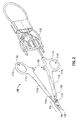
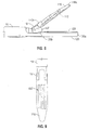
- Fig. 1 depicts a bipolar forceps 10 for use in connection with endoscopic surgical procedures
- Fig. 2 depicts an open forceps 100 contemplated for use in connection with traditional open surgical procedures.
- an endoscopic instrument or an open instrument may be utilized with the end effector assembly described herein.
- the novel aspects with respect to the end effector assembly and its operating characteristics remain generally consistent with respect to both the open or endoscopic designs.
- Fig. 1 shows a bipolar forceps 10 for use with various endoscopic surgical procedures and generally includes a housing 20, a handle assembly 30, a rotating assembly 80, a switch assembly 70 and an end effector assembly 105 having opposing jaw members 110 and 120 that mutually cooperate to grasp, seal and divide tubular vessels and vascular tissue. More particularly, forceps 10 includes a shaft 12 that has a distal end 16 dimensioned to mechanically engage the end effector assembly 105 and a proximal end 14 that mechanically engages the housing 20.
- the shaft 12 may include one or more known mechanically engaging components that are designed to securely receive and engage the end effector assembly 105 such that the jaw members 110 and 120 are pivotable relative to one another to engage and grasp tissue therebetween.
- proximal end 14 of shaft 12 mechanically engages the rotating assembly 80 (the connection not shown in detail) to facilitate rotation of the end effector assembly 105.
- distal will refer to the end of the forceps 10 which is closer to the user, while the term “distal” will refer to the end which is further from the user.
- Handle assembly 30 includes a fixed handle 50 and a movable handle 40.
- Fixed handle 50 is integrally associated with housing 20 and handle 40 is movable relative to fixed handle 50 to actuate the opposing jaw members 110 and 120 of the end effector assembly 105 as explained in more detail below.
- Movable handle 40 and switch assembly 70 are of unitary construction and are operatively connected to the housing 20 and the fixed handle 50 during the assembly process.
- Housing 20 is constructed from two components halves 20a and 20b that are assembled about the proximal end of shaft 12 during assembly.
- Switch assembly 70 is configured to selectively provide electrical energy to the end effector assembly 105.
- end effector assembly 105 is attached to the distal end 16 of shaft 12 and includes the opposing jaw members 110 and 120.
- Movable handle 40 of handle assembly 30 imparts movement of the jaw members 110 and 120 from an open position wherein the jaw members 110 and 120 are disposed in spaced relation relative to one another, to a clamping or closed position wherein the jaw members 110 and 120 cooperate to grasp tissue therebetween.
- an open forceps 100 includes a pair of elongated shaft portions 111 a and 111b each having a proximal end 114a and 114b, respectively, and a distal end 116a and 116b, respectively.
- the forceps 100 includes jaw members 120 and 110 that attach to distal ends 116a and 116b of shafts 111a and 111b, respectively.
- the jaw members 110 and 120 are connected about pivot pin 119 which allows the jaw members 110 and 120 to pivot relative to one another from the first to second positions for treating tissue.
- the end effector assembly 105 is connected to opposing jaw members 110 and 120 and may include electrical connections through or around the pivot pin 119.
- Each shaft 111a and 111b includes a handle 117a and 117b disposed at the proximal end 114a and 114b thereof which each define a finger hole 118a and 118b, respectively, therethrough for receiving a finger of the user.
- Finger holes 118a and 118b facilitate movement of the shafts 111 a and 111 b relative to one another which, in turn, pivot the jaw members 110 and 120 from the open position wherein the jaw members 110 and 120 are disposed in spaced relation relative to one another to the clamping or closed position wherein the jaw members 110 and 120 cooperate to grasp tissue therebetween.
- a ratchet 130 is included for selectively locking the jaw members 110 and 120 relative to one another at various positions during pivoting.
- forceps 10 or 100 also includes an electrical cable 210 that connects the forceps 10, 100 to a source of electrosurgical energy, e.g., an electrosurgical generator (not shown). Cable 210 extends through the shaft(s) 12, 111 to transmit electrosurgical energy through various electrical feed paths to the end effector assembly 105.
- a source of electrosurgical energy e.g., an electrosurgical generator (not shown).
- Cable 210 extends through the shaft(s) 12, 111 to transmit electrosurgical energy through various electrical feed paths to the end effector assembly 105.
- each jaw member 110 and 120 of both the endoscopic forceps of Fig. 1 and the open forceps of Fig. 2 include similar component features which cooperate to permit rotation about pivot 19, 119, respectively, to effect the grasping and sealing of tissue.
- Each jaw member 110 and 120 includes an electrically conductive tissue sealing plate 112 and 122, respectively.
- Tissue sealing plates 112, 122 of jaw members 110, 120, respectively, define opposed electrically conductive tissue sealing surfaces that cooperate to seal tissue.
- each jaw member 110 and 120 also includes a static bipolar cutting portion 127 disposed thereon, although it is also envisioned that only one of the jaw members 110, 120 need include a static cutting portion 127.
- one (or both) jaw members e.g., jaw member 120
- static cutting portions 127 are disposed toward proximal ends 110b, 120b of jaw members 110 and 120, respectively, while dynamic cutting portion 137 is disposed toward a distal end 120a of jaw member 120.
- static and dynamic bipolar cutting portions 127, 137 may be positioned at different locations on either or both of jaw members 110 and 120, as will be described in more detail below.
- the combination of sealing plates 112, 122, static cutting portion(s) 127 and dynamic cutting portion(s) 137 allows for sealing, static cutting, and dynamic dissection of tissue with a single surgical device 10, 100.
- the various electrical connections of the end effector assembly 105 are configured to provide electrical continuity to the tissue sealing plates 112 and 122 and the cutting portions 127, 137 through the end effector assembly 105.
- cable lead 210 ( Fig. 1 ) may be configured to include four different leads (not shown) that carry different electrical potentials. The cable leads are fed through shaft 12 and connect to various electrical connectors (not shown) which ultimately connect to the electrically conductive sealing plates 112 and 122 and cutting portions 127, 137.
- the various electrical connections from cable lead 210 are dielectrically insulated from one another to allow selective and independent activation of either the tissue sealing plates 112 and 122 or the static and/or dynamic cutting portions 127, 137, respectively, as will be explained in more detail below.
- the end effector assembly 105 may include a single connector that includes an internal switch (not shown) to allow selective and independent activation of the tissue sealing plates 112, 122 and/or the cutting portions 127, 137.
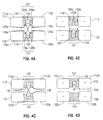
- FIGs. 4A-4B several electrical configurations of the static cutting portion(s) 127 are shown which, in conjunction with the opposed sealing plates 112, 122, are designed to effectively seal and cut tissue disposed between opposing jaw members 110 and 120, respectively.
- the configuration of static cutting potion(s) 127 disposed between sealing plates 112, 122 shown in Figs. 4A and 4B are example configurations designed to effect both tissue sealing and static tissue cutting, that is, tissue cutting wherein the jaw members 110, 120 remain stationary relative to tissue to be cut. More particularly, during a sealing mode, sealing plates 112 and 122 are activated to supply electrosurgical energy through tissue to effect a tissue seal.
- static cutting portion(s) 127 are activated to apply electrosurgical energy through tissue to effect tissue division.
- Other configurations of static cutting portions 127 capable of effecting both tissue sealing and cutting may be provided, such as those disclosed in commonly-owned U.S. Patent No. 7,270,664 entitled “VESSEL SEALING INSTRUMENT WITH ELECTRICAL CUTTING MECHANISM”. Further, it is envisioned that similar, or different configurations of the static cutting portions 127 may be provided on each of the jaw members 110, 120.
- each of the static cutting portions 127 includes an insulator 129 and an electrically conductive cutting element 128 e.g., an electrically energizeable electrode.
- Insulators 129 are disposed between the electrically conductive sealing plates 112, 122 to divide each of the electrically conductive sealing plates 112, 122 into sections of electrically conductive sealing plates 112a, 112b and 122a, 122b on each jaw member 110 and 120, respectively.
- insulators 129 are disposed between sections 112a and 112b and sections 122a and 122b, of sealing plates 112 and 122, respectively.
- Each insulator 129 is generally centered between a respective tissue sealing plate 112a, 112b and 122a, 122b such that the two insulators 129 of the respective jaw members 110, 120 generally oppose one another. Further, each insulator 129 includes a pair of tabs 129a extending therefrom adjacent each of the sealing plate sections 112a, 112b, 122a, 122b and a recessed portion 129b defined between the tabs 129a and the electrodes 128.
- Fig. 4B The embodiment shown in Fig. 4B is substantially similar to the embodiment of Fig. 4A except that jaw member 110 includes an insulator 140 disposed between the sections 112a and 112b of sealing plate 112, rather than a static cutting portion 127 having both a cutting element 128 and an insulator 129.
- the electrically conductive cutting elements 128 of static cutting portions 127 are disposed substantially within or disposed on the insulators 129. With respect to Fig. 4A , the cutting elements 128 are electrically conductive; however, one or both of the cutting elements 128 may be made from an insulative material with a conductive coating disposed thereon or one (or both) of the cutting elements may be non-conductive (not shown).
- FIGs. 4C-4D several electrical configurations of the dynamic cutting portion(s) 137 are shown.
- the dynamic cutting portions 137 are shown disposed between electrically conductive sealing plate sections 112a, 112b and 122a, 122b of respective electrically conductive sealing plates 112, 122, similarly to the static cutting portions 127 shown in Figs. 4A-4B and described above.
- Figs. 4C-4D the dynamic cutting portions 137 are shown disposed between electrically conductive sealing plate sections 112a, 112b and 122a, 122b of respective electrically conductive sealing plates 112, 122, similarly to the static cutting portions 127 shown in Figs. 4A-4B and described above.
- Figs. 4C-4D several electrical configurations of the dynamic cutting portion(s) 137 are shown.
- the dynamic cutting portions 137 are shown disposed between electrically conductive sealing plate sections 112a, 112b and 122a, 122b of respective electrically conductive sealing plates 112, 122, similarly to the static cutting portions
- the static cutting portions 127 may be positioned between the sections 112a, 112b, 122a, 122b of sealing plates 112, 122 toward the proximal ends 110b and 120b of jaw members 110 and 120, respectively, while the dynamic cutting portions 137 are positioned between the sealing plates 112, 122 toward the distal ends 110a and 120a of the jaw members 110 and 120, respectively.
- This configuration may also be reversed, e.g., where the static cutting portions 127 are disposed toward the distal ends 110a and 120a and where the dynamic cutting portions 137 are disposed toward the proximal ends 110b and 120b of the jaw members 110 and 120, respectively.
- the dynamic cutting portions 137 may be disposed in various other positions on either or both jaw members 110, 120.
- the dynamic cutting portions 137 include an electrically conductive cutting element 138, e.g., an electrically energizeable electrode, positioned within and extending from an insulator 139 disposed between the electrically conductive sealing plates 112, 122, much like the configuration of the static cutting portions 127 discussed above ( Fig. 4A-4B ).
- the embodiment shown in Fig. 4D is similar to the embodiment of Fig. 4A except that jaw member 120 includes an insulator 140 disposed between the sections 122a and 122b of sealing plate 122 and does not include a cutting element 138 therein.
- Insulators 139 of dynamic cutting portions 137 are different from insulators 129 of static cutting portions 127 ( Figs. 4A-4B ) in that the surfaces of insulators 139 are generally flat and do not include tabs or recesses. It has been found that this configuration of dynamic cutting portions 137, namely, the configuration of insulators 139, helps facilitate dissection, or dynamic tissue cutting, i.e., cutting of tissue while the jaw members 110 and/or 120 are moved relative to tissue.
- the configuration of static cutting portions 127 ( Figs. 4A-4B ), on the other hand, has been found to help facilitate static electrosurgical cutting.
- the static cutting portions may define a variety of configurations, e.g., the configurations disclosed in commonly-owned U.S. Patent No. 7,270,664 or the configurations of Figs. 4A-4B , which facilitate static electrosurgical cutting.
- the dynamic cutting portions may define a variety of configurations, including those disclosed in U.S. Patent No. 7,270,664 or the configurations shown in Figs. 4C-4D , which facilitate dynamic electrosurgical dissection.
- the static and dynamic cutting portions may be configured differently, each configuration being adapted for a particular application, e.g., static or dynamic bipolar electrosurgical cutting.
- dynamic cutting portions 137 are shown disposed at various positions on jaw member 120. Although dynamic cutting portions 137 are shown disposed on jaw member 120, it is envisioned that dynamic cutting portions 137 may be similarly disposed on jaw member 110 in cooperation with or in place of the dynamic cutting portions 137 of jaw member 120. Further, the positioning of dynamic cutting potions 137 shown in Figs. 5A-9 are examples and other positions are contemplated.
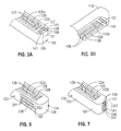
- Fig. 5A shows jaw member 120 including an electrically conductive sealing plate 122 including sealing plate sections 122a and 122b having static cutting portion 127 disposed therebetween.
- static cutting portion 127 includes an electrically energizeable electrode, or cutting element 128, and a pair of insulators 129 configured for static electrosurgical cutting.
- dynamic cutting portion 137 is shown including a dynamic cutting element 138 and a pair of insulators 139 configured for dynamic electrosurgical cutting. Sealing plate sections 122a and 122b may extend toward the distal end of jaw member 120 to surround the dynamic cutting portion 137, or, as shown in Fig.
- a pair of electrically conductive elements 141 may be positioned surrounding the insulators 139 to act as return electrode.
- jaw member 110 includes sealing plates 112a, 122b and static cutting portion 127 disposed therebetween.
- Jaw member 110 also includes an insulator 140 opposing dynamic cutting portion 137 of jaw member 120; however, jaw member 110 may include a dynamic cutting portion 137 in place of, or in addition to, dynamic cutting portion 137 disposed on jaw member 120.
- Figs. 6-9 illustrate various different positionings of the dynamic cutting portion.
- a dynamic cutting portion 237 is disposed on a longitudinal side 123 of jaw member 120.
- Dynamic cutting portion 237 may be disposed on either longitudinal side 123 of jaw member 120 and/or jaw member 110 and may be positioned toward a distal end 120a of the jaw member 120, or toward the proximal end 110b, 120b of either (or both) of the jaw members 110, 120, as desired.
- a dynamic cutting portion 337 is disposed on a distal tip 121 of jaw member 120.
- Dynamic cutting portion 337 may be aligned vertically, as shown in Fig. 7 , or may be aligned horizontally on jaw member 110 and/or jaw member 120.
- Each dynamic cutting portion 237 and 337 shown in Figs. 6 and 7 , respectively, includes a cutting element 238, 338, which may be an electrically energizeable electrode 238, 338.
- Dynamic cutting portion 237, 337 also include insulators (not explicitly shown) which may be defined as the portion 125, 126 of insulated outer housing 124 of jaw member 120 surrounding the cutting element 238, 338.
- insulators not explicitly shown
- a pair of electrically conductive elements, or return electrodes 241, 341 are provided surrounding the cutting element 238, 338, with the insulators, e.g., the portions 125, 126 of insulated outer housing 124, therebetween.
- dynamic cutting portions 137, 237, 337 are configured for bipolar electrosurgical cutting, e.g., each cutting portion 137, 237, 337 includes an electrically energizeable cutting element 138, 238, 338 and a pair of return electrodes, e.g., sealing plates 112, 122 or electrically conductive elements 141, 241, 341, thus obviating the need for a remote return pad, as is required for monopolar cutting.
- Fig. 8 shows another configuration wherein a dynamic cutting portion 437 is disposed adjacent pivot 19 of jaw members 110, 120. More particularly, dynamic cutting portion 437 is positioned between jaw members 110, 120 at proximal ends 110b, 120b, respectively, thereof such that, upon distal advancement of the forceps with jaw members 110, 120 in the open position, tissue disposed between jaw members 110, 120 may be electrically transected, or cut via dynamic cutting portion 437. Dynamic cutting portion 437 may be configured similarly to any of the dynamic cutting portions described above.
- Fig. 9 shows yet another configuration wherein a dynamic cutting portion 537 is disposed on an outer, top surface of jaw member 110, although dynamic cutting portion 537 may alternatively be disposed on an outer, bottom surface of jaw member 120.
- Dynamic cutting portion 537 is configured for bipolar electrosurgical cutting, obviating the need for a remote return pad, as is required for monopolar cutting.
- forceps 10 will now be described in detail. More specifically, the tissue sealing, static tissue cutting and dynamic tissue cutting modes, or phases of forceps 10 will be described with reference to Figs. 5A-9 . As shown in the drawings, the various polarities of the components are shown corresponding to the "cutting" phases, and thus do not represent the relative polarities of the components during the sealing phase.
- forceps 10 is initially positioned such that jaw members 110 and 120 of end effector assembly 105 are disposed in the open position with tissue to be sealed therebetween.
- the jaw members 110, 120 are then moved to the closed position, clamping, or grasping tissue between electrically conductive sealing plates 112 and 122 of jaw members 110 and 120, respectively.
- the cutting elements 128 (and 138) are configured to extend from their respective insulators 129, respectively, beyond the sealing plates 112a, 112b and 122a and 122b such that the cutting elements 128 (and 138) act as stop members (i.e., create a gap distance "G" between opposing sealing surfaces of sealing plates 112 and 122) which promote accurate, consistent and effective tissue sealing.
- the opposing sealing plates 112a, 122a and 112b, 122b are activated, i.e., electrosurgical energy from a generator is supplied to sealing plates 112, 122 to seal the tissue disposed therebetween.
- sealing plate 112 is energized to a first potential "+” and sealing plate 122 is energized to a second potential "-".
- the cutting element 128 is not energized. Since the insulator 129 does not conduct energy as well as the conductive sealing plates 112, 122, the first potential is not effectively or. efficiently transferred to the cutting element 128 and the tissue is not necessarily heated or damaged during the sealing phase.
- energy is transferred from sealing plate sections 112a and 112b and through tissue to the return electrode, or return sealing plate sections 122a and 122b.
- the static cutting element 128 of the static cutting portion 127 (and the dynamic cutting element 138 of dynamic cutting portion 137) mainly acts as a stop member for creating and maintaining a gap between the opposing sealing plates 112 and 122.
- the static cutting element(s) 128 may be independently activated, e.g., energized with electrosurgical energy, by the user or automatically activated by a generator (not shown) or other energy source to effect tissue cutting.
- a generator not shown
- the electrical potential to sealing plates 112, 122 is turned off, static cutting element 128 of jaw member 110 is energized with a first electrical potential "+” and static cutting element 128 of jaw member 120 is energized with a second electrical potential "-" (see Fig. 4A ).
- the static cutting element 128 of jaw members 120 may be energized with a first electrical potential "+” and opposing sealing plates 112 and 122 may be energized with a second electrical potential "-" (see Fig.
- tissue may be initially sealed and thereafter cut using the static electrosurgical cutting portion 127 without re-grasping the tissue.
- the dynamic cutting element 138, 238, 338 is activated to a first electrical potential "+” and the opposing sealing plates 112 and 122 ( Fig. 4D ) or electrically conductive elements 141, 241, 341 ( Figs. 5A-7 ) are activated to a second electrical potential "-".
- dynamic cutting element 138 of jaw member 110 may be activated to the first electrical potential "+” while dynamic cutting element 138 of jaw member 120 is activated to the second electrical potential "-".
- the activated dynamic cutting portions 137, 237, 337 create a concentrated electrical path between the potentials "+” any "-" to cut the tissue as the end effector assembly 105 is advanced through tissue.
- Jaw members 110 and 120 are opened slightly during translation of end effector assembly 105 in the embodiment of Figs. 5A-5B to effect dynamic bipolar cutting of tissue.
- end effector assembly 105 is translated laterally, in the direction of dynamic cutting portions 237, 537, respectively, to effect tissue dissection.
- the end effector assembly 105 is translated distally to effect electrosurgical tissue dissection via dynamic cutting portion 337, 437, in the embodiments of Fig. 7 and 8 , respectively.
- any combination of electrical potentials as described herein or in U.S. Patent No. 7,270,664 may be utilized with the various jaw members 110, 120 and/or cutting portions 127, 137 to effectively seal tissue during an electrical sealing phase and cut tissue during static and/or dynamic electrical cutting phases.
- sealing plates 112 and 122 of jaw members 110 and 120, static and dynamic cutting elements 128, 138, 238, 338 of static and dynamic cutting portions 127, 137, 237, 337, respectively, and/or electrically conductive element 141, 241, 341, may be energized with any combination of first and second electrical potential(s) (or other electrical potentials) to effectively seal and/or cut tissue.
- the forceps 10, 100 is configured to operate in three modes or phases: (1) electrosurgical tissue sealing, (2) static bipolar electrosurgical cutting, and (3) dynamic bipolar electrosurgical cutting.
- the sealing plates 112, 122, the static cutting portions 127 and the dynamic cutting portions 137 are configured to seal, statically cut, and dynamically cut tissue, respectively.
- all three functions may be carried out with a single device, e.g. endoscopic forceps 10 or open forceps 100. It is envisioned that various manually operated and/or automatic switching mechanisms may be employed to alternate between the sealing and cutting modes.
- forceps 10 may be configured as a handheld, battery-powered device.
- the battery (not shown) may be disposed within fixed handle 50 and may be configured to provide electrosurgical energy to the end effector assembly 105.
Description
- The present disclosure relates to a surgical forceps, and more particularly, to an electrosurgical forceps capable of sealing, cutting, and dissecting tissue.
- Open or endoscopic electrosurgical forceps utilize both mechanical clamping action and electrical energy to effect hemostasis. The electrode of each opposing jaw member is charged to a different electric potential such that when the jaw members grasp tissue, electrical energy can be selectively transferred through the tissue. A surgeon can either cauterize, coagulate/desiccate and/or simply reduce or slow bleeding, by controlling the intensity, frequency and duration of the electrosurgical energy applied between the electrodes and through the tissue.
- Certain surgical procedures require more than simply cauterizing tissue and rely on the combination of clamping pressure, electrosurgical energy and gap distance to "seal" tissue, vessels and certain vascular bundles. "Vessel sealing" is defined as the process of liquefying the collagen, elastin and ground substances in the tissue so that the tissue reforms into a fused mass with significantly-reduced demarcation between the opposing tissue structures.
- Typically, once a vessel is sealed, the surgeon has to remove the sealing instrument from the operative site, substitute a new instrument, and accurately sever the vessel along the newly formed tissue seal. As can be appreciated, this additional step may be both time consuming (particularly when sealing a significant number of vessels) and may contribute to imprecise separation of the tissue along the sealing line due to the misalignment or misplacement of the severing instrument along the center of the tissue seal.
- Several attempts have been made to design an instrument which incorporates a knife or blade member which effectively severs the tissue after forming a tissue seal. For example,
U.S. Patent No. 5,674,220 to Fox et al. discloses a transparent instrument which includes a longitudinally reciprocating knife which severs the tissue once sealed. The instrument includes a plurality of openings which enable direct visualization of the tissue during the treatment and severing processes. This direct visualization allows a user to visually and manually regulate the closure force and gap distance between jaw members to reduce and/or limit certain undesirable visual effects known to occur when treating vessels, thermal spread, charring, etc. As can be appreciated, the overall success of creating an effective tissue seal with this instrument is greatly reliant upon the user's expertise, vision, dexterity, and experience in judging the appropriate closure force, gap distance and length of reciprocation of the knife to uniformly, consistently and effectively seal the vessel and separate the tissue at the seal along an ideal cutting plane -
U.S. Patent No. 5,702,390 to Austin et al. discloses an instrument which includes a triangularly-shaped electrode which is rotatable from a first position to treat tissue to a second position to cut tissue. Again, the user must rely on direct visualization and expertise to control the various effects of treating and cutting tissue. -
US-A-2002/0188294 discloses an endoscopic bipolar forceps for sealing and dividing tissue including an elongated shaft having opposing jaw members at a distal end thereof which are movable relative to one another from a first position wherein the jaw members are disposed in spaced relation relative to one another to a second position wherein the jaw members cooperate to grasp tissue therebetween. Each jaw member includes an electrically conductive sealing surface having a non-stick coating disposed thereon which is designed to reduce tissue adherence. A source of electrical energy is connected to each jaw member such that the jaw members are capable of conducting energy through tissue held therebetween to effect a seal. A longitudinally reciprocating knife is included which severs tissue proximate the seal. The vessel sealer and divider also includes a non-conductive stop member disposed on the electrically conductive surface of one of the jaw members which controls the distance between the jaw members when tissue is held therebetween. -
EP-A-1 920 725 discloses an endoscopic forceps including a housing having a shaft attached thereto, the shaft including a pair of jaw members disposed at a distal end thereof. The forceps also includes a drive assembly disposed in the housing which moves the jaw members relative to one another from a first position wherein the jaw members are disposed in spaced relation relative to one another to a second position wherein the jaw members are closer to one another for manipulating tissue. Each of the jaw members is adapted to connect to a source of electrical energy such that the jaw members are capable of conducting energy for treating tissue. The endoscopic forceps further includes a knife assembly operatively associated with the housing, the knife assembly being selectively actuatable to advance a knife through tissue disposed between the jaw members when the jaw members are disposed in the second position, the knife assembly including at least one safety mechanism to prevent damaging the knife upon selective actuation thereof. -
WO-A-2009/032623 discloses a surgical instrument including an ablation device. The ablation device includes an elongated flexible member having a proximal end and a distal end. The flexible member includes first and second lumens. A first needle electrode is configured to slideably move within the first lumen. A second needle electrode is located within the second lumen. The first and second needle electrodes are adapted to couple to an electrical waveform generator and to receive an electrical waveform sufficient to electrically ablate tissue located between the first and second needle electrodes. A clamp jaw portion may be located at the distal end of the elongated flexible member. The clamp jaw portion is operatively movable from an open position to a closed position. A cutting blade may be located in the clamp jaw portion. A blunt dissection portion may be formed on the clamp jaw portion. The clamp jaw portion is adapted to couple to an electrical waveform generator and to receive an electrical waveform. - The invention is set out in the claims.
- In accordance with the present disclosure, an end effector assembly for use with an electrosurgical instrument, e.g., a forceps, is provided. The end effector assembly includes first and second jaw members disposed in opposed relation relative to one another. One or both of the jaw members are moveable relative to the other from an open position to a closed position in which the jaw members cooperate to grasp tissue therebetween. Each jaw member includes an electrically conductive tissue sealing surface adapted to connect to a source of electrosurgical energy such that the sealing surfaces are capable of conducting electrosurgical energy through tissue disposed between the jaw members. A static bipolar electrosurgical cutting portion is disposed on one or both of the jaw members and includes one or more electrically conductive cutting elements and one or more insulating elements having a first configuration. The static cutting portion electrically cuts tissue disposed between the jaw members upon activation of the cutting element and an opposing sealing surface and/or an opposing cutting element. A dynamic electrosurgical cutting portion is disposed on one or bolh of the jaw members and includes one or more electrically conductive cutting elements and one or more insulating elements having a second configuration. The dynamic cutting portion is configured for electrically transecting tissue during movement relative to tissue grasped between the jaw members.
- In one embodiment, the end effector assembly is configured to operate in a first, sealing mode wherein the sealing surfaces are activated to seal tissue. The end effector assembly may also be configured to operate in a second, cutting mode, wherein the static cutting portion and/or the dynamic cutting portion are activated to cut tissue.
- In another embodiment, the static cutting portion is disposed at a proximal end of an opposed surface of one or both of the jaw members and the dynamic cutting portion is disposed at a distal end of the opposed surface of one or both of the jaw members.
- In yet another embodiment, the dynamic cutting portion is disposed on a longitudinal side of one or both of the jaw members.
- In still another embodiment, the dynamic cutting portion is disposed on a distal tip of one or both of the jaw members.
- In still yet another embodiment, each of the sealing surfaces includes a pair of spaced apart sealing surface sections. One or more of the insulating element(s) of the static cutting portion is disposed between the pair of spaced apart sealing surface sections. The electrically conductive cutting element of the static cutting portion may be partially disposed within the insulating element disposed between the pair of spaced apart sealing surface sections.
- In yet another embodiment, the opposed surfaces of each of the jaw members are symmetrical with respect to each other. Alternatively, the opposed surfaces of each of the jaw members may be asymmetrical with respect to each other.
- In an embodiment, the one or more electrically conductive cutting elements of the dynamic electrosurgical cutting portion is shorter in length than that of the static electrosurgical cutting portion. In an embodiment, the static any dynamic cutting portions are spaced apart from one another, preferably with respect to a direction along the sealing surfaces, preferably longitudinally with respect to a longitudinal extent of the sealing surfaces. In an embodiment, the static and dynamic cutting elements are electrically isolated from one another and include connections so that the dynamic and static cutting portions are independently electrically activatable. In an embodiment, the sealing surfaces are provided along one plane when the jaw members are closed, the static cutting element extend along that phase and the dynamic cutting element extends along that plane or along a transverse plane to that plane.
- Various embodiments of the subject instrument are described herein with reference to the drawings wherein:
-
Fig. 1 is a right, perspective view of an endoscopic bipolar forceps including a housing, a shaft and an end effector assembly; -
Fig. 2 is a left, perspective view of an open bipolar forceps showing a pair of first and second shafts having an end effector assembly disposed at a distal end thereof; -
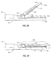
Fig. 3A is an enlarged, side view of the end effector assembly ofFig. 1 with a pair of jaw members in the open position; -
Fig. 3B is an enlarged, side view of the end effector assembly ofFig. 1 with the pair of jaw members in the closed position; -
Fig. 4A is a schematic of one configuration of tissue sealing surfaces and static cutting portions that may be used with the end effector assembly ofFig. 1 ; -
Fig. 4B is a schematic of another configuration of the tissue sealing surfaces and the static cutting portion that may be used with the end effector assembly ofFig. 1 ; -
Fig. 4C is a schematic of one configuration of the tissue sealing surfaces and dynamic cutting portions that may be used with the end effector assembly ofFig. 1 ; -
Fig. 4D is a schematic of another configuration of the tissue sealing surfaces and the dynamic cutting portion that may be used with the end effector assembly ofFig. 1 ; -
Fig. 5A is a front, perspective view of a bottom jaw member that may be used with the end effector assembly ofFig. 1 showing the tissue sealing surfaces and static and dynamic cutting portions according to another embodiment of the present disclosure; -
Fig. 5B is a rear, perspective view of a top jaw member that may be used with the end effector assembly ofFig. 1 showing the sealing surfaces and static cutting portion in accordance with yet another embodiment of the present disclosure; -
Fig. 6 is a front, perspective view of yet another embodiment showing the static and dynamic cutting portions of a bottom jaw member that may be used with the end effector assembly ofFig. 1 ; -
Fig. 7 is a front, perspective view of still yet another embodiment showing the static and dynamic cutting portions of a bottom jaw member that may be used with the end effector assembly ofFig. 1 -
Fig. 8 is an enlarged, side view of yet another embodiment showing the dynamic cutting portion disposed adjacent a pivot of the jaw members of the end effector assembly ofFig. 1 ; and -
Fig. 9 is a top view of still another embodiment showing the dynamic cutting portion of a top jaw member that may be used with the end effector assembly ofFig. 1 . - Referring now to
Figs. 1 and2 ,Fig. 1 depicts abipolar forceps 10 for use in connection with endoscopic surgical procedures andFig. 2 depicts anopen forceps 100 contemplated for use in connection with traditional open surgical procedures. For the purposes herein, either an endoscopic instrument or an open instrument may be utilized with the end effector assembly described herein. Obviously, different electrical and mechanical connections and considerations apply to each particular type of instrument, however, the novel aspects with respect to the end effector assembly and its operating characteristics remain generally consistent with respect to both the open or endoscopic designs. -
Fig. 1 shows abipolar forceps 10 for use with various endoscopic surgical procedures and generally includes ahousing 20, ahandle assembly 30, a rotatingassembly 80, aswitch assembly 70 and anend effector assembly 105 having opposingjaw members forceps 10 includes ashaft 12 that has adistal end 16 dimensioned to mechanically engage theend effector assembly 105 and aproximal end 14 that mechanically engages thehousing 20. Theshaft 12 may include one or more known mechanically engaging components that are designed to securely receive and engage theend effector assembly 105 such that thejaw members - The
proximal end 14 ofshaft 12 mechanically engages the rotating assembly 80 (the connection not shown in detail) to facilitate rotation of theend effector assembly 105. In the drawings and in the descriptions which follow, the term "proximal", as is traditional, will refer to the end of theforceps 10 which is closer to the user, while the term "distal" will refer to the end which is further from the user. - Handle
assembly 30 includes a fixedhandle 50 and amovable handle 40. Fixedhandle 50 is integrally associated withhousing 20 and handle 40 is movable relative to fixedhandle 50 to actuate the opposingjaw members end effector assembly 105 as explained in more detail below.Movable handle 40 and switchassembly 70 are of unitary construction and are operatively connected to thehousing 20 and the fixedhandle 50 during the assembly process.Housing 20 is constructed from twocomponents halves shaft 12 during assembly.Switch assembly 70 is configured to selectively provide electrical energy to theend effector assembly 105. - As mentioned above,
end effector assembly 105 is attached to thedistal end 16 ofshaft 12 and includes the opposingjaw members Movable handle 40 ofhandle assembly 30 imparts movement of thejaw members jaw members jaw members - Referring now to
Fig. 2 , anopen forceps 100 includes a pair ofelongated shaft portions proximal end distal end forceps 100 includesjaw members distal ends shafts jaw members pivot pin 119 which allows thejaw members end effector assembly 105 is connected to opposingjaw members pivot pin 119. - Each
shaft handle proximal end finger hole Finger holes shafts jaw members jaw members jaw members ratchet 130 is included for selectively locking thejaw members - As shown in
Figs. 1 and2 ,forceps electrical cable 210 that connects theforceps Cable 210 extends through the shaft(s) 12, 111 to transmit electrosurgical energy through various electrical feed paths to theend effector assembly 105. - Referring now to the schematic illustrations of
Figs. 3A-3B , thejaw members Fig. 1 and the open forceps ofFig. 2 include similar component features which cooperate to permit rotation aboutpivot jaw member tissue sealing plate Tissue sealing plates jaw members Figs. 3A-3B , eachjaw member bipolar cutting portion 127 disposed thereon, although it is also envisioned that only one of thejaw members static cutting portion 127. Further, one (or both) jaw members, e.g.,jaw member 120, includes a dynamicbipolar cutting portion 137. As shown inFigs. 3A-3B ,static cutting portions 127 are disposed toward proximal ends 110b, 120b ofjaw members dynamic cutting portion 137 is disposed toward adistal end 120a ofjaw member 120. However, static and dynamicbipolar cutting portions jaw members plates surgical device - The various electrical connections of the
end effector assembly 105 are configured to provide electrical continuity to thetissue sealing plates portions end effector assembly 105. For example, cable lead 210 (Fig. 1 ) may be configured to include four different leads (not shown) that carry different electrical potentials. The cable leads are fed throughshaft 12 and connect to various electrical connectors (not shown) which ultimately connect to the electricallyconductive sealing plates portions cable lead 210 are dielectrically insulated from one another to allow selective and independent activation of either thetissue sealing plates dynamic cutting portions end effector assembly 105 may include a single connector that includes an internal switch (not shown) to allow selective and independent activation of thetissue sealing plates portions - As best seen in
Figs. 4A-4B , several electrical configurations of the static cutting portion(s) 127 are shown which, in conjunction with the opposed sealingplates jaw members plates Figs. 4A and 4B are example configurations designed to effect both tissue sealing and static tissue cutting, that is, tissue cutting wherein thejaw members plates static cutting portions 127 capable of effecting both tissue sealing and cutting may be provided, such as those disclosed in commonly-ownedU.S. Patent No. 7,270,664 entitled "VESSEL SEALING INSTRUMENT WITH ELECTRICAL CUTTING MECHANISM". Further, it is envisioned that similar, or different configurations of thestatic cutting portions 127 may be provided on each of thejaw members - With reference to the embodiment of
Fig. 4A , each of thestatic cutting portions 127 includes aninsulator 129 and an electricallyconductive cutting element 128 e.g., an electrically energizeable electrode.Insulators 129 are disposed between the electricallyconductive sealing plates conductive sealing plates conductive sealing plates jaw member insulators 129 are disposed betweensections sections plates insulator 129 is generally centered between a respectivetissue sealing plate insulators 129 of therespective jaw members insulator 129 includes a pair oftabs 129a extending therefrom adjacent each of the sealingplate sections portion 129b defined between thetabs 129a and theelectrodes 128. - The embodiment shown in
Fig. 4B is substantially similar to the embodiment ofFig. 4A except thatjaw member 110 includes aninsulator 140 disposed between thesections plate 112, rather than astatic cutting portion 127 having both acutting element 128 and aninsulator 129. - The electrically
conductive cutting elements 128 ofstatic cutting portions 127 are disposed substantially within or disposed on theinsulators 129. With respect toFig. 4A , the cuttingelements 128 are electrically conductive; however, one or both of the cuttingelements 128 may be made from an insulative material with a conductive coating disposed thereon or one (or both) of the cutting elements may be non-conductive (not shown). - With reference now to
Figs. 4C-4D , several electrical configurations of the dynamic cutting portion(s) 137 are shown. InFigs. 4C-4D , thedynamic cutting portions 137 are shown disposed between electrically conductivesealing plate sections conductive sealing plates static cutting portions 127 shown inFigs. 4A-4B and described above. In these embodiments, as shown inFigs. 3A-3B , thestatic cutting portions 127 may be positioned between thesections plates jaw members dynamic cutting portions 137 are positioned between the sealingplates jaw members static cutting portions 127 are disposed toward the distal ends 110a and 120a and where thedynamic cutting portions 137 are disposed toward the proximal ends 110b and 120b of thejaw members dynamic cutting portions 137 may be disposed in various other positions on either or bothjaw members - As shown in
Fig. 4C , thedynamic cutting portions 137 include an electricallyconductive cutting element 138, e.g., an electrically energizeable electrode, positioned within and extending from aninsulator 139 disposed between the electricallyconductive sealing plates static cutting portions 127 discussed above (Fig. 4A-4B ). The embodiment shown inFig. 4D is similar to the embodiment ofFig. 4A except thatjaw member 120 includes aninsulator 140 disposed between thesections plate 122 and does not include acutting element 138 therein. -
Insulators 139 of dynamic cutting portions 137 (Figs. 4C-4D ) are different frominsulators 129 of static cutting portions 127 (Figs. 4A-4B ) in that the surfaces ofinsulators 139 are generally flat and do not include tabs or recesses. It has been found that this configuration ofdynamic cutting portions 137, namely, the configuration ofinsulators 139, helps facilitate dissection, or dynamic tissue cutting, i.e., cutting of tissue while thejaw members 110 and/or 120 are moved relative to tissue. The configuration of static cutting portions 127 (Figs. 4A-4B ), on the other hand, has been found to help facilitate static electrosurgical cutting. - Put more generally, it has been found that some electrical configurations, e.g., the configuration of static cutting portions 127 (
Figs. 4A-4B ), are more advantageous for static electrosurgical cutting, while other electrical configurations, e.g., the configuration of dynamic cutting portions 137 (Figs. 4C-4D ), are more advantageous for dynamic electrosurgical tissue dissection. Thus, the static cutting portions may define a variety of configurations, e.g., the configurations disclosed in commonly-ownedU.S. Patent No. 7,270,664 or the configurations ofFigs. 4A-4B , which facilitate static electrosurgical cutting. The dynamic cutting portions may define a variety of configurations, including those disclosed inU.S. Patent No. 7,270,664 or the configurations shown inFigs. 4C-4D , which facilitate dynamic electrosurgical dissection. As mentioned above, the static and dynamic cutting portions may be configured differently, each configuration being adapted for a particular application, e.g., static or dynamic bipolar electrosurgical cutting. - With reference now to
Figs. 5A-9 ,dynamic cutting portions 137 are shown disposed at various positions onjaw member 120. Althoughdynamic cutting portions 137 are shown disposed onjaw member 120, it is envisioned thatdynamic cutting portions 137 may be similarly disposed onjaw member 110 in cooperation with or in place of thedynamic cutting portions 137 ofjaw member 120. Further, the positioning of dynamic cuttingpotions 137 shown inFigs. 5A-9 are examples and other positions are contemplated. -
Fig. 5A showsjaw member 120 including an electricallyconductive sealing plate 122 including sealingplate sections static cutting portion 127 disposed therebetween. As mentioned above,static cutting portion 127 includes an electrically energizeable electrode, or cuttingelement 128, and a pair ofinsulators 129 configured for static electrosurgical cutting. Toward a distal end ofjaw member 120,dynamic cutting portion 137 is shown including adynamic cutting element 138 and a pair ofinsulators 139 configured for dynamic electrosurgical cutting. Sealingplate sections jaw member 120 to surround thedynamic cutting portion 137, or, as shown inFig. 5A , a pair of electricallyconductive elements 141 may be positioned surrounding theinsulators 139 to act as return electrode. As shown inFig. 5B ,jaw member 110 includes sealingplates static cutting portion 127 disposed therebetween.Jaw member 110 also includes aninsulator 140 opposingdynamic cutting portion 137 ofjaw member 120; however,jaw member 110 may include adynamic cutting portion 137 in place of, or in addition to,dynamic cutting portion 137 disposed onjaw member 120. -
Figs. 6-9 illustrate various different positionings of the dynamic cutting portion. As shown inFig. 6 , adynamic cutting portion 237 is disposed on alongitudinal side 123 ofjaw member 120. Dynamic cuttingportion 237 may be disposed on eitherlongitudinal side 123 ofjaw member 120 and/orjaw member 110 and may be positioned toward adistal end 120a of thejaw member 120, or toward theproximal end jaw members Fig. 7 , adynamic cutting portion 337 is disposed on adistal tip 121 ofjaw member 120. Dynamic cuttingportion 337 may be aligned vertically, as shown inFig. 7 , or may be aligned horizontally onjaw member 110 and/orjaw member 120. - Each
dynamic cutting portion Figs. 6 and 7 , respectively, includes acutting element energizeable electrode portion portion outer housing 124 ofjaw member 120 surrounding the cuttingelement electrodes element portions outer housing 124, therebetween. It should be noted thatdynamic cutting portions portion energizeable cutting element plates conductive elements -
Fig. 8 shows another configuration wherein adynamic cutting portion 437 is disposedadjacent pivot 19 ofjaw members dynamic cutting portion 437 is positioned betweenjaw members proximal ends jaw members jaw members dynamic cutting portion 437. Dynamic cuttingportion 437 may be configured similarly to any of the dynamic cutting portions described above. -
Fig. 9 shows yet another configuration wherein adynamic cutting portion 537 is disposed on an outer, top surface ofjaw member 110, althoughdynamic cutting portion 537 may alternatively be disposed on an outer, bottom surface ofjaw member 120. Dynamic cuttingportion 537 is configured for bipolar electrosurgical cutting, obviating the need for a remote return pad, as is required for monopolar cutting. - The operation of
forceps 10 will now be described in detail. More specifically, the tissue sealing, static tissue cutting and dynamic tissue cutting modes, or phases offorceps 10 will be described with reference toFigs. 5A-9 . As shown in the drawings, the various polarities of the components are shown corresponding to the "cutting" phases, and thus do not represent the relative polarities of the components during the sealing phase. - To effect tissue sealing,
forceps 10 is initially positioned such thatjaw members end effector assembly 105 are disposed in the open position with tissue to be sealed therebetween. Thejaw members conductive sealing plates jaw members respective insulators 129, respectively, beyond the sealingplates plates 112 and 122) which promote accurate, consistent and effective tissue sealing. - During sealing, the opposing
sealing plates plates - More specifically, during sealing, sealing
plate 112 is energized to a first potential "+" and sealingplate 122 is energized to a second potential "-". The cuttingelement 128 is not energized. Since theinsulator 129 does not conduct energy as well as theconductive sealing plates cutting element 128 and the tissue is not necessarily heated or damaged during the sealing phase. During the sealing phase, energy is transferred from sealingplate sections plate sections static cutting element 128 of the static cutting portion 127 (and thedynamic cutting element 138 of dynamic cutting portion 137) mainly acts as a stop member for creating and maintaining a gap between the opposing sealingplates - Once sealing is complete, the static cutting element(s) 128 may be independently activated, e.g., energized with electrosurgical energy, by the user or automatically activated by a generator (not shown) or other energy source to effect tissue cutting. During the static cutting mode, or phase, the electrical potential to sealing
plates static cutting element 128 ofjaw member 110 is energized with a first electrical potential "+" andstatic cutting element 128 ofjaw member 120 is energized with a second electrical potential "-" (seeFig. 4A ). Alternatively, thestatic cutting element 128 ofjaw members 120 may be energized with a first electrical potential "+" and opposing sealingplates Fig. 4B ). In either embodiment, a concentrated electrical path is created between the potentials "+" and "-" through the tissue to cut the tissue between the previously formed tissue seal. Hence, tissue may be initially sealed and thereafter cut using the staticelectrosurgical cutting portion 127 without re-grasping the tissue. - However, it may be desirable, depending on the surgical procedure to be performed, to effect dynamic tissue dissection, or cutting, either before, after, or in place of tissue sealing and/or static cutting. To effect dynamic electrosurgical dissection, the
dynamic cutting element plates 112 and 122 (Fig. 4D ) or electricallyconductive elements Figs. 5A-7 ) are activated to a second electrical potential "-". Alternatively, as shown inFig. 4C ,dynamic cutting element 138 ofjaw member 110 may be activated to the first electrical potential "+" whiledynamic cutting element 138 ofjaw member 120 is activated to the second electrical potential "-". As with thestatic cutting portions 127, the activateddynamic cutting portions end effector assembly 105 is advanced through tissue.Jaw members end effector assembly 105 in the embodiment ofFigs. 5A-5B to effect dynamic bipolar cutting of tissue. In the embodiments ofFigs. 6 and9 ,end effector assembly 105 is translated laterally, in the direction ofdynamic cutting portions end effector assembly 105 is translated distally to effect electrosurgical tissue dissection viadynamic cutting portion Fig. 7 and8 , respectively. - Any combination of electrical potentials as described herein or in
U.S. Patent No. 7,270,664 may be utilized with thevarious jaw members portions plates jaw members dynamic cutting elements dynamic cutting portions conductive element - As can be appreciated from the description above, the
forceps plates static cutting portions 127 and thedynamic cutting portions 137 are configured to seal, statically cut, and dynamically cut tissue, respectively. Thus, all three functions may be carried out with a single device, e.g. endoscopic forceps 10 oropen forceps 100. It is envisioned that various manually operated and/or automatic switching mechanisms may be employed to alternate between the sealing and cutting modes. - Additionally, and particularly with reference to
Fig. 1 ,forceps 10 may be configured as a handheld, battery-powered device. The battery (not shown) may be disposed within fixedhandle 50 and may be configured to provide electrosurgical energy to theend effector assembly 105.
Claims (11)
- An end effector assembly (105) for use with an electrosurgical instrument (10), the end effector assembly comprising:first and second jaw members (110, 120) disposed in opposed relation relative to one another, at least one of the jaw members moveable relative to the other from a first, open position to a second, closed position wherein jaw members cooperate to grasp tissue therebetween;each jaw member including an electrically conductive tissue sealing surface (112, 122) adapted to connect to a source of electrosurgical energy such that the sealing surfaces are capable of conducting electrosurgical energy through tissue disposed between the jaw members;characterized in that the end effector assembly further comprises:a static electrosurgical cutting portion (127) disposed on at least one of the jaw members, the static cutting portion including at least one electrically conductive cutting element (128) and at least one insulating element (129) having a first configuration, the static cutting portion configured to electrically cut tissue disposed between the jaw members upon activation of the cutting element and at least one of an opposing sealing surface and an opposing cutting element; anda dynamic electrosurgical cutting portion (137) disposed on at least one of the jaw members, the dynamic cutting portion including at least one electrically conductive cutting element (138) and at least one insulating element (139) having a second configuration, the dynamic cutting portion capable of electrically transecting tissue during movement relative to tissue grasped between the jaw members.
- The end effector assembly according to Claim 1, wherein the end effector assembly is configured to operate in a first, sealing mode wherein the sealing surfaces are activated to seal tissue.
- The end effector assembly according to Claim 1 or 2, wherein the end effector assembly is configured to operate in a second, cutting mode wherein at least one of the static cutting portion and the dynamic cutting portion is activated to cut tissue.
- The end effector assembly according to Claim 1, 2 or 3, wherein the static cutting portion is disposed at a proximal end of an opposed surface of at least one of the jaw members and wherein the dynamic cutting portion is disposed at a distal end of the opposed surface of at least one of the jaw members.
- The end effector assembly according to Claim 1, 2 or 3, wherein the dynamic cutting portion is disposed on a longitudinal side of at least one of the jaw members.
- The end effector assembly according to Claim 1, 2 or 3, wherein the dynamic cutting portion is disposed on a distal tip of at least one of the jaw members.
- The end effector assembly according to any one of the preceding claims, wherein each of the sealing surfaces includes a pair of spaced apart sealing surface sections and wherein one of the at least one insulating elements of the static cutting portion is disposed between the pair of spaced apart sealing surface sections.
- The end effector assembly according to Claim 7, wherein the electrically conductive cutting element of the static cutting portion is at least partially disposed within the insulating element disposed between the pair of spaced apart sealing surface sections.
- The end effector assembly according to any one of the preceding claims, wherein opposed surfaces of each of the jaw members are symmetrical with respect to each other.
- The end effector assembly according to any one of Claims 1 to 8, wherein opposed surfaces of each of the jaw members are asymmetrical with respect to each other.
- The end effector assembly according to any one of the preceding claims, wherein the surface of the at least one insulating element of the dynamic electrosurgical cutting portion is flat.
Priority Applications (1)
| Application Number | Priority Date | Filing Date | Title |
|---|---|---|---|
| EP16186852.6A EP3178427B1 (en) | 2010-09-07 | 2011-09-06 | Dynamic bipolar electrical sealing and cutting device |
Applications Claiming Priority (1)
| Application Number | Priority Date | Filing Date | Title |
|---|---|---|---|
| US12/876,668 US8663222B2 (en) | 2010-09-07 | 2010-09-07 | Dynamic and static bipolar electrical sealing and cutting device |
Related Child Applications (2)
| Application Number | Title | Priority Date | Filing Date |
|---|---|---|---|
| EP16186852.6A Division-Into EP3178427B1 (en) | 2010-09-07 | 2011-09-06 | Dynamic bipolar electrical sealing and cutting device |
| EP16186852.6A Division EP3178427B1 (en) | 2010-09-07 | 2011-09-06 | Dynamic bipolar electrical sealing and cutting device |
Publications (2)
| Publication Number | Publication Date |
|---|---|
| EP2425791A1 EP2425791A1 (en) | 2012-03-07 |
| EP2425791B1 true EP2425791B1 (en) | 2016-11-02 |
Family
ID=44677624
Family Applications (2)
| Application Number | Title | Priority Date | Filing Date |
|---|---|---|---|
| EP11180182.5A Active EP2425791B1 (en) | 2010-09-07 | 2011-09-06 | Dynamic and static bipolar electrical sealing and cutting device |
| EP16186852.6A Active EP3178427B1 (en) | 2010-09-07 | 2011-09-06 | Dynamic bipolar electrical sealing and cutting device |
Family Applications After (1)
| Application Number | Title | Priority Date | Filing Date |
|---|---|---|---|
| EP16186852.6A Active EP3178427B1 (en) | 2010-09-07 | 2011-09-06 | Dynamic bipolar electrical sealing and cutting device |
Country Status (5)
| Country | Link |
|---|---|
| US (3) | US8663222B2 (en) |
| EP (2) | EP2425791B1 (en) |
| JP (1) | JP5767914B2 (en) |
| AU (3) | AU2011218765B2 (en) |
| CA (1) | CA2751312C (en) |
Families Citing this family (294)
| Publication number | Priority date | Publication date | Assignee | Title |
|---|---|---|---|---|
| US7364577B2 (en) | 2002-02-11 | 2008-04-29 | Sherwood Services Ag | Vessel sealing system |
| DE60121229T2 (en) | 2001-04-06 | 2007-05-24 | Sherwood Services Ag | DEVICE FOR SEALING AND SHARING A VESSEL WITH NON-LASTING END STOP |
| US11229472B2 (en) | 2001-06-12 | 2022-01-25 | Cilag Gmbh International | Modular battery powered handheld surgical instrument with multiple magnetic position sensors |
| US9848938B2 (en) | 2003-11-13 | 2017-12-26 | Covidien Ag | Compressible jaw configuration with bipolar RF output electrodes for soft tissue fusion |
| US7367976B2 (en) | 2003-11-17 | 2008-05-06 | Sherwood Services Ag | Bipolar forceps having monopolar extension |
| US8182501B2 (en) | 2004-02-27 | 2012-05-22 | Ethicon Endo-Surgery, Inc. | Ultrasonic surgical shears and method for sealing a blood vessel using same |
| JP5009159B2 (en) | 2004-10-08 | 2012-08-22 | エシコン・エンド−サージェリィ・インコーポレイテッド | Ultrasonic surgical instrument |
| US7628791B2 (en) | 2005-08-19 | 2009-12-08 | Covidien Ag | Single action tissue sealer |
| CA2561034C (en) | 2005-09-30 | 2014-12-09 | Sherwood Services Ag | Flexible endoscopic catheter with an end effector for coagulating and transfecting tissue |
| US20070191713A1 (en) | 2005-10-14 | 2007-08-16 | Eichmann Stephen E | Ultrasonic device for cutting and coagulating |
| US7621930B2 (en) | 2006-01-20 | 2009-11-24 | Ethicon Endo-Surgery, Inc. | Ultrasound medical instrument having a medical ultrasonic blade |
| US8057498B2 (en) | 2007-11-30 | 2011-11-15 | Ethicon Endo-Surgery, Inc. | Ultrasonic surgical instrument blades |
| US8911460B2 (en) | 2007-03-22 | 2014-12-16 | Ethicon Endo-Surgery, Inc. | Ultrasonic surgical instruments |
| US8142461B2 (en) | 2007-03-22 | 2012-03-27 | Ethicon Endo-Surgery, Inc. | Surgical instruments |
| US8808319B2 (en) | 2007-07-27 | 2014-08-19 | Ethicon Endo-Surgery, Inc. | Surgical instruments |
| US8523889B2 (en) | 2007-07-27 | 2013-09-03 | Ethicon Endo-Surgery, Inc. | Ultrasonic end effectors with increased active length |
| US8512365B2 (en) | 2007-07-31 | 2013-08-20 | Ethicon Endo-Surgery, Inc. | Surgical instruments |
| US9044261B2 (en) | 2007-07-31 | 2015-06-02 | Ethicon Endo-Surgery, Inc. | Temperature controlled ultrasonic surgical instruments |
| US8430898B2 (en) | 2007-07-31 | 2013-04-30 | Ethicon Endo-Surgery, Inc. | Ultrasonic surgical instruments |
| US8623027B2 (en) | 2007-10-05 | 2014-01-07 | Ethicon Endo-Surgery, Inc. | Ergonomic surgical instruments |
| US10010339B2 (en) | 2007-11-30 | 2018-07-03 | Ethicon Llc | Ultrasonic surgical blades |
| ES2944288T3 (en) | 2008-03-31 | 2023-06-20 | Applied Med Resources | Electrosurgical system with means to determine the end of a treatment based on a phase angle |
| US9089360B2 (en) | 2008-08-06 | 2015-07-28 | Ethicon Endo-Surgery, Inc. | Devices and techniques for cutting and coagulating tissue |
| US8142473B2 (en) | 2008-10-03 | 2012-03-27 | Tyco Healthcare Group Lp | Method of transferring rotational motion in an articulating surgical instrument |
| US8114122B2 (en) | 2009-01-13 | 2012-02-14 | Tyco Healthcare Group Lp | Apparatus, system, and method for performing an electrosurgical procedure |
| US8187273B2 (en) | 2009-05-07 | 2012-05-29 | Tyco Healthcare Group Lp | Apparatus, system, and method for performing an electrosurgical procedure |
| US9700339B2 (en) | 2009-05-20 | 2017-07-11 | Ethicon Endo-Surgery, Inc. | Coupling arrangements and methods for attaching tools to ultrasonic surgical instruments |
| US8246618B2 (en) | 2009-07-08 | 2012-08-21 | Tyco Healthcare Group Lp | Electrosurgical jaws with offset knife |
| US8663220B2 (en) | 2009-07-15 | 2014-03-04 | Ethicon Endo-Surgery, Inc. | Ultrasonic surgical instruments |
| US8133254B2 (en) | 2009-09-18 | 2012-03-13 | Tyco Healthcare Group Lp | In vivo attachable and detachable end effector assembly and laparoscopic surgical instrument and methods therefor |
| US8112871B2 (en) | 2009-09-28 | 2012-02-14 | Tyco Healthcare Group Lp | Method for manufacturing electrosurgical seal plates |
| US10441345B2 (en) | 2009-10-09 | 2019-10-15 | Ethicon Llc | Surgical generator for ultrasonic and electrosurgical devices |
| US10172669B2 (en) | 2009-10-09 | 2019-01-08 | Ethicon Llc | Surgical instrument comprising an energy trigger lockout |
| US11090104B2 (en) | 2009-10-09 | 2021-08-17 | Cilag Gmbh International | Surgical generator for ultrasonic and electrosurgical devices |
| US8986302B2 (en) | 2009-10-09 | 2015-03-24 | Ethicon Endo-Surgery, Inc. | Surgical generator for ultrasonic and electrosurgical devices |
| US8951272B2 (en) | 2010-02-11 | 2015-02-10 | Ethicon Endo-Surgery, Inc. | Seal arrangements for ultrasonically powered surgical instruments |
| US8486096B2 (en) | 2010-02-11 | 2013-07-16 | Ethicon Endo-Surgery, Inc. | Dual purpose surgical instrument for cutting and coagulating tissue |
| US8469981B2 (en) | 2010-02-11 | 2013-06-25 | Ethicon Endo-Surgery, Inc. | Rotatable cutting implement arrangements for ultrasonic surgical instruments |
| US8834518B2 (en) | 2010-04-12 | 2014-09-16 | Ethicon Endo-Surgery, Inc. | Electrosurgical cutting and sealing instruments with cam-actuated jaws |
| US8709035B2 (en) | 2010-04-12 | 2014-04-29 | Ethicon Endo-Surgery, Inc. | Electrosurgical cutting and sealing instruments with jaws having a parallel closure motion |
| US8685020B2 (en) | 2010-05-17 | 2014-04-01 | Ethicon Endo-Surgery, Inc. | Surgical instruments and end effectors therefor |
| GB2480498A (en) | 2010-05-21 | 2011-11-23 | Ethicon Endo Surgery Inc | Medical device comprising RF circuitry |
| US9005199B2 (en) | 2010-06-10 | 2015-04-14 | Ethicon Endo-Surgery, Inc. | Heat management configurations for controlling heat dissipation from electrosurgical instruments |
| US9028495B2 (en) | 2010-06-23 | 2015-05-12 | Covidien Lp | Surgical instrument with a separable coaxial joint |
| US8795327B2 (en) | 2010-07-22 | 2014-08-05 | Ethicon Endo-Surgery, Inc. | Electrosurgical instrument with separate closure and cutting members |
| US9192431B2 (en) | 2010-07-23 | 2015-11-24 | Ethicon Endo-Surgery, Inc. | Electrosurgical cutting and sealing instrument |
| US8795269B2 (en) | 2010-07-26 | 2014-08-05 | Covidien Lp | Rotary tissue sealer and divider |
| US8814864B2 (en) | 2010-08-23 | 2014-08-26 | Covidien Lp | Method of manufacturing tissue sealing electrodes |
| US8663222B2 (en) | 2010-09-07 | 2014-03-04 | Covidien Lp | Dynamic and static bipolar electrical sealing and cutting device |
| US9498278B2 (en) | 2010-09-08 | 2016-11-22 | Covidien Lp | Asymmetrical electrodes for bipolar vessel sealing |
| US9005200B2 (en) | 2010-09-30 | 2015-04-14 | Covidien Lp | Vessel sealing instrument |
| US9017372B2 (en) | 2010-10-01 | 2015-04-28 | Covidien Lp | Blade deployment mechanisms for surgical forceps |
| US8979890B2 (en) | 2010-10-01 | 2015-03-17 | Ethicon Endo-Surgery, Inc. | Surgical instrument with jaw member |
| ES2664081T3 (en) | 2010-10-01 | 2018-04-18 | Applied Medical Resources Corporation | Electrosurgical system with a radio frequency amplifier and with means for adapting to the separation between electrodes |
| US9655672B2 (en) | 2010-10-04 | 2017-05-23 | Covidien Lp | Vessel sealing instrument |
| US8932293B2 (en) | 2010-11-17 | 2015-01-13 | Covidien Lp | Method and apparatus for vascular tissue sealing with reduced energy consumption |
| US8945175B2 (en) | 2011-01-14 | 2015-02-03 | Covidien Lp | Latch mechanism for surgical instruments |
| US9113940B2 (en) | 2011-01-14 | 2015-08-25 | Covidien Lp | Trigger lockout and kickback mechanism for surgical instruments |
| US8939972B2 (en) | 2011-05-06 | 2015-01-27 | Covidien Lp | Surgical forceps |
| US8900232B2 (en) | 2011-05-06 | 2014-12-02 | Covidien Lp | Bifurcated shaft for surgical instrument |
| US8685009B2 (en) | 2011-05-16 | 2014-04-01 | Covidien Lp | Thread-like knife for tissue cutting |
| US8852185B2 (en) | 2011-05-19 | 2014-10-07 | Covidien Lp | Apparatus for performing an electrosurgical procedure |
| US9615877B2 (en) | 2011-06-17 | 2017-04-11 | Covidien Lp | Tissue sealing forceps |
| US9039732B2 (en) | 2011-07-11 | 2015-05-26 | Covidien Lp | Surgical forceps |
| US8745840B2 (en) | 2011-07-11 | 2014-06-10 | Covidien Lp | Surgical forceps and method of manufacturing thereof |
| US9259265B2 (en) | 2011-07-22 | 2016-02-16 | Ethicon Endo-Surgery, Llc | Surgical instruments for tensioning tissue |
| US9044243B2 (en) | 2011-08-30 | 2015-06-02 | Ethcon Endo-Surgery, Inc. | Surgical cutting and fastening device with descendible second trigger arrangement |
| US8845636B2 (en) | 2011-09-16 | 2014-09-30 | Covidien Lp | Seal plate with insulation displacement connection |
| US8864795B2 (en) | 2011-10-03 | 2014-10-21 | Covidien Lp | Surgical forceps |
| US9314295B2 (en) | 2011-10-20 | 2016-04-19 | Covidien Lp | Dissection scissors on surgical device |
| US9492221B2 (en) | 2011-10-20 | 2016-11-15 | Covidien Lp | Dissection scissors on surgical device |
| US8968308B2 (en) | 2011-10-20 | 2015-03-03 | Covidien Lp | Multi-circuit seal plates |
| US9314292B2 (en) | 2011-10-24 | 2016-04-19 | Ethicon Endo-Surgery, Llc | Trigger lockout mechanism |
| USD680220S1 (en) | 2012-01-12 | 2013-04-16 | Coviden IP | Slider handle for laparoscopic device |
| EP2811932B1 (en) | 2012-02-10 | 2019-06-26 | Ethicon LLC | Robotically controlled surgical instrument |
| US9011435B2 (en) | 2012-02-24 | 2015-04-21 | Covidien Lp | Method for manufacturing vessel sealing instrument with reduced thermal spread |
| US8887373B2 (en) | 2012-02-24 | 2014-11-18 | Covidien Lp | Vessel sealing instrument with reduced thermal spread and method of manufacture therefor |
| US9439668B2 (en) | 2012-04-09 | 2016-09-13 | Ethicon Endo-Surgery, Llc | Switch arrangements for ultrasonic surgical instruments |
| US11871901B2 (en) | 2012-05-20 | 2024-01-16 | Cilag Gmbh International | Method for situational awareness for surgical network or surgical network connected device capable of adjusting function based on a sensed situation or usage |
| US20140005640A1 (en) | 2012-06-28 | 2014-01-02 | Ethicon Endo-Surgery, Inc. | Surgical end effector jaw and electrode configurations |
| US20140005705A1 (en) | 2012-06-29 | 2014-01-02 | Ethicon Endo-Surgery, Inc. | Surgical instruments with articulating shafts |
| US9198714B2 (en) | 2012-06-29 | 2015-12-01 | Ethicon Endo-Surgery, Inc. | Haptic feedback devices for surgical robot |
| US9408622B2 (en) | 2012-06-29 | 2016-08-09 | Ethicon Endo-Surgery, Llc | Surgical instruments with articulating shafts |
| US9326788B2 (en) | 2012-06-29 | 2016-05-03 | Ethicon Endo-Surgery, Llc | Lockout mechanism for use with robotic electrosurgical device |
| US9226767B2 (en) | 2012-06-29 | 2016-01-05 | Ethicon Endo-Surgery, Inc. | Closed feedback control for electrosurgical device |
| US20140005702A1 (en) | 2012-06-29 | 2014-01-02 | Ethicon Endo-Surgery, Inc. | Ultrasonic surgical instruments with distally positioned transducers |
| US9393037B2 (en) | 2012-06-29 | 2016-07-19 | Ethicon Endo-Surgery, Llc | Surgical instruments with articulating shafts |
| US9820768B2 (en) | 2012-06-29 | 2017-11-21 | Ethicon Llc | Ultrasonic surgical instruments with control mechanisms |
| US9351754B2 (en) | 2012-06-29 | 2016-05-31 | Ethicon Endo-Surgery, Llc | Ultrasonic surgical instruments with distally positioned jaw assemblies |
| US9192421B2 (en) | 2012-07-24 | 2015-11-24 | Covidien Lp | Blade lockout mechanism for surgical forceps |
| WO2014022585A1 (en) * | 2012-08-01 | 2014-02-06 | Caymus Medical Inc. | Systems and methods for percutaneous intravascular access for arteriovenous fistula |
| BR112015007010B1 (en) | 2012-09-28 | 2022-05-31 | Ethicon Endo-Surgery, Inc | end actuator |
| US9095367B2 (en) | 2012-10-22 | 2015-08-04 | Ethicon Endo-Surgery, Inc. | Flexible harmonic waveguides/blades for surgical instruments |
| US20140135804A1 (en) | 2012-11-15 | 2014-05-15 | Ethicon Endo-Surgery, Inc. | Ultrasonic and electrosurgical devices |
| US9572622B2 (en) * | 2012-12-10 | 2017-02-21 | Ethicon Endo-Surgery, Llc | Bipolar electrosurgical features for targeted hemostasis |
| US20140221994A1 (en) * | 2013-02-05 | 2014-08-07 | Covidien Lp | Electrosurgical instrument |
| US9655673B2 (en) | 2013-03-11 | 2017-05-23 | Covidien Lp | Surgical instrument |
| US10226273B2 (en) | 2013-03-14 | 2019-03-12 | Ethicon Llc | Mechanical fasteners for use with surgical energy devices |
| AU2013397838B2 (en) | 2013-08-07 | 2018-08-16 | Covidien Lp | Bipolar surgical instrument with tissue stop |
| EP3030178B1 (en) | 2013-08-07 | 2019-01-09 | Covidien LP | Bipolar surgical instrument |
| US9295514B2 (en) | 2013-08-30 | 2016-03-29 | Ethicon Endo-Surgery, Llc | Surgical devices with close quarter articulation features |
| US9814514B2 (en) | 2013-09-13 | 2017-11-14 | Ethicon Llc | Electrosurgical (RF) medical instruments for cutting and coagulating tissue |
| US9943357B2 (en) * | 2013-09-16 | 2018-04-17 | Covidien Lp | Split electrode for use in a bipolar electrosurgical instrument |
| US9861428B2 (en) | 2013-09-16 | 2018-01-09 | Ethicon Llc | Integrated systems for electrosurgical steam or smoke control |
| US9717548B2 (en) * | 2013-09-24 | 2017-08-01 | Covidien Lp | Electrode for use in a bipolar electrosurgical instrument |
| US9526565B2 (en) | 2013-11-08 | 2016-12-27 | Ethicon Endo-Surgery, Llc | Electrosurgical devices |
| US9265926B2 (en) | 2013-11-08 | 2016-02-23 | Ethicon Endo-Surgery, Llc | Electrosurgical devices |
| GB2521229A (en) | 2013-12-16 | 2015-06-17 | Ethicon Endo Surgery Inc | Medical device |
| GB2521228A (en) | 2013-12-16 | 2015-06-17 | Ethicon Endo Surgery Inc | Medical device |
| US9795436B2 (en) | 2014-01-07 | 2017-10-24 | Ethicon Llc | Harvesting energy from a surgical generator |
| US9408660B2 (en) | 2014-01-17 | 2016-08-09 | Ethicon Endo-Surgery, Llc | Device trigger dampening mechanism |
| US10231776B2 (en) | 2014-01-29 | 2019-03-19 | Covidien Lp | Tissue sealing instrument with tissue-dissecting electrode |
| US9554854B2 (en) | 2014-03-18 | 2017-01-31 | Ethicon Endo-Surgery, Llc | Detecting short circuits in electrosurgical medical devices |
| US10092310B2 (en) | 2014-03-27 | 2018-10-09 | Ethicon Llc | Electrosurgical devices |
| US10463421B2 (en) | 2014-03-27 | 2019-11-05 | Ethicon Llc | Two stage trigger, clamp and cut bipolar vessel sealer |
| US10524852B1 (en) | 2014-03-28 | 2020-01-07 | Ethicon Llc | Distal sealing end effector with spacers |
| US9737355B2 (en) | 2014-03-31 | 2017-08-22 | Ethicon Llc | Controlling impedance rise in electrosurgical medical devices |
| US9913680B2 (en) | 2014-04-15 | 2018-03-13 | Ethicon Llc | Software algorithms for electrosurgical instruments |
| US9757186B2 (en) | 2014-04-17 | 2017-09-12 | Ethicon Llc | Device status feedback for bipolar tissue spacer |
| US9345512B2 (en) * | 2014-05-01 | 2016-05-24 | Tariq Ibrahim Altokhais | Circumcision instrument |
| KR20230076143A (en) | 2014-05-16 | 2023-05-31 | 어플라이드 메디컬 리소시스 코포레이션 | Electrosurgical system |
| CA2949242A1 (en) | 2014-05-30 | 2015-12-03 | Applied Medical Resources Corporation | Electrosurgical seal and dissection systems |
| US9700333B2 (en) | 2014-06-30 | 2017-07-11 | Ethicon Llc | Surgical instrument with variable tissue compression |
| US10285724B2 (en) | 2014-07-31 | 2019-05-14 | Ethicon Llc | Actuation mechanisms and load adjustment assemblies for surgical instruments |
| EP3087941B1 (en) * | 2014-08-05 | 2020-03-11 | Olympus Corporation | Therapeutic treatment system |
| US20160038224A1 (en) * | 2014-08-11 | 2016-02-11 | Covidien Lp | Surgical instruments and methods for performing tonsillectomy and adenoidectomy procedures |
| US10194976B2 (en) | 2014-08-25 | 2019-02-05 | Ethicon Llc | Lockout disabling mechanism |
| US9877776B2 (en) | 2014-08-25 | 2018-01-30 | Ethicon Llc | Simultaneous I-beam and spring driven cam jaw closure mechanism |
| US10194972B2 (en) | 2014-08-26 | 2019-02-05 | Ethicon Llc | Managing tissue treatment |
| EP3222239B1 (en) * | 2014-11-18 | 2022-04-20 | Olympus Corporation | Treatment tool and treatment system |
| US10639092B2 (en) | 2014-12-08 | 2020-05-05 | Ethicon Llc | Electrode configurations for surgical instruments |
| US9848937B2 (en) | 2014-12-22 | 2017-12-26 | Ethicon Llc | End effector with detectable configurations |
| US10111699B2 (en) | 2014-12-22 | 2018-10-30 | Ethicon Llc | RF tissue sealer, shear grip, trigger lock mechanism and energy activation |
| US10092348B2 (en) | 2014-12-22 | 2018-10-09 | Ethicon Llc | RF tissue sealer, shear grip, trigger lock mechanism and energy activation |
| US10159524B2 (en) | 2014-12-22 | 2018-12-25 | Ethicon Llc | High power battery powered RF amplifier topology |
| KR20230093365A (en) | 2014-12-23 | 2023-06-27 | 어플라이드 메디컬 리소시스 코포레이션 | Bipolar electrosurgical sealer and divider |
| GB2534147B (en) | 2015-01-14 | 2018-11-14 | Gyrus Medical Ltd | Manufacturing electrosurgical instruments |
| GB2535006B (en) | 2015-01-14 | 2018-12-12 | Gyrus Medical Ltd | End effector for electrosurgical instrument |
| GB2535003B (en) | 2015-01-14 | 2018-12-12 | Gyrus Medical Ltd | Electrosurgical instrument |
| GB2535627B (en) | 2015-01-14 | 2017-06-28 | Gyrus Medical Ltd | Electrosurgical system |
| US10245095B2 (en) | 2015-02-06 | 2019-04-02 | Ethicon Llc | Electrosurgical instrument with rotation and articulation mechanisms |
| US10342602B2 (en) | 2015-03-17 | 2019-07-09 | Ethicon Llc | Managing tissue treatment |
| US10321950B2 (en) | 2015-03-17 | 2019-06-18 | Ethicon Llc | Managing tissue treatment |
| US10595929B2 (en) | 2015-03-24 | 2020-03-24 | Ethicon Llc | Surgical instruments with firing system overload protection mechanisms |
| US10314638B2 (en) | 2015-04-07 | 2019-06-11 | Ethicon Llc | Articulating radio frequency (RF) tissue seal with articulating state sensing |
| US10117702B2 (en) | 2015-04-10 | 2018-11-06 | Ethicon Llc | Surgical generator systems and related methods |
| JP6062131B1 (en) * | 2015-04-13 | 2017-01-18 | オリンパス株式会社 | Grasping treatment unit |
| US10130410B2 (en) | 2015-04-17 | 2018-11-20 | Ethicon Llc | Electrosurgical instrument including a cutting member decouplable from a cutting member trigger |
| US9872725B2 (en) | 2015-04-29 | 2018-01-23 | Ethicon Llc | RF tissue sealer with mode selection |
| US11020140B2 (en) | 2015-06-17 | 2021-06-01 | Cilag Gmbh International | Ultrasonic surgical blade for use with ultrasonic surgical instruments |
| US10357303B2 (en) | 2015-06-30 | 2019-07-23 | Ethicon Llc | Translatable outer tube for sealing using shielded lap chole dissector |
| US11141213B2 (en) | 2015-06-30 | 2021-10-12 | Cilag Gmbh International | Surgical instrument with user adaptable techniques |
| US10034704B2 (en) | 2015-06-30 | 2018-07-31 | Ethicon Llc | Surgical instrument with user adaptable algorithms |
| US11051873B2 (en) | 2015-06-30 | 2021-07-06 | Cilag Gmbh International | Surgical system with user adaptable techniques employing multiple energy modalities based on tissue parameters |
| US10898256B2 (en) | 2015-06-30 | 2021-01-26 | Ethicon Llc | Surgical system with user adaptable techniques based on tissue impedance |
| US11129669B2 (en) | 2015-06-30 | 2021-09-28 | Cilag Gmbh International | Surgical system with user adaptable techniques based on tissue type |
| US10154852B2 (en) | 2015-07-01 | 2018-12-18 | Ethicon Llc | Ultrasonic surgical blade with improved cutting and coagulation features |
| WO2017031712A1 (en) | 2015-08-26 | 2017-03-02 | Covidien Lp | Electrosurgical end effector assemblies and electrosurgical forceps configured to reduce thermal spread |
| US11033322B2 (en) | 2015-09-30 | 2021-06-15 | Ethicon Llc | Circuit topologies for combined generator |
| US10959771B2 (en) | 2015-10-16 | 2021-03-30 | Ethicon Llc | Suction and irrigation sealing grasper |
| US10548655B2 (en) * | 2015-10-16 | 2020-02-04 | Ethicon Llc | Control and electrical connections for electrode endocutter device |
| US10595930B2 (en) | 2015-10-16 | 2020-03-24 | Ethicon Llc | Electrode wiping surgical device |
| US10959806B2 (en) | 2015-12-30 | 2021-03-30 | Ethicon Llc | Energized medical device with reusable handle |
| US10179022B2 (en) | 2015-12-30 | 2019-01-15 | Ethicon Llc | Jaw position impedance limiter for electrosurgical instrument |
| US10575892B2 (en) | 2015-12-31 | 2020-03-03 | Ethicon Llc | Adapter for electrical surgical instruments |
| US11051840B2 (en) | 2016-01-15 | 2021-07-06 | Ethicon Llc | Modular battery powered handheld surgical instrument with reusable asymmetric handle housing |
| US11229471B2 (en) | 2016-01-15 | 2022-01-25 | Cilag Gmbh International | Modular battery powered handheld surgical instrument with selective application of energy based on tissue characterization |
| US10716615B2 (en) | 2016-01-15 | 2020-07-21 | Ethicon Llc | Modular battery powered handheld surgical instrument with curved end effectors having asymmetric engagement between jaw and blade |
| US11129670B2 (en) | 2016-01-15 | 2021-09-28 | Cilag Gmbh International | Modular battery powered handheld surgical instrument with selective application of energy based on button displacement, intensity, or local tissue characterization |
| US10426543B2 (en) | 2016-01-23 | 2019-10-01 | Covidien Lp | Knife trigger for vessel sealer |
| US10555769B2 (en) | 2016-02-22 | 2020-02-11 | Ethicon Llc | Flexible circuits for electrosurgical instrument |
| US10702329B2 (en) | 2016-04-29 | 2020-07-07 | Ethicon Llc | Jaw structure with distal post for electrosurgical instruments |
| US10646269B2 (en) | 2016-04-29 | 2020-05-12 | Ethicon Llc | Non-linear jaw gap for electrosurgical instruments |
| US10485607B2 (en) | 2016-04-29 | 2019-11-26 | Ethicon Llc | Jaw structure with distal closure for electrosurgical instruments |
| US10987156B2 (en) | 2016-04-29 | 2021-04-27 | Ethicon Llc | Electrosurgical instrument with electrically conductive gap setting member and electrically insulative tissue engaging members |
| US10856934B2 (en) | 2016-04-29 | 2020-12-08 | Ethicon Llc | Electrosurgical instrument with electrically conductive gap setting and tissue engaging members |
| US10456193B2 (en) | 2016-05-03 | 2019-10-29 | Ethicon Llc | Medical device with a bilateral jaw configuration for nerve stimulation |
| US10245064B2 (en) | 2016-07-12 | 2019-04-02 | Ethicon Llc | Ultrasonic surgical instrument with piezoelectric central lumen transducer |
| US10893883B2 (en) | 2016-07-13 | 2021-01-19 | Ethicon Llc | Ultrasonic assembly for use with ultrasonic surgical instruments |
| US10842522B2 (en) | 2016-07-15 | 2020-11-24 | Ethicon Llc | Ultrasonic surgical instruments having offset blades |
| US10682154B2 (en) | 2016-08-02 | 2020-06-16 | Covidien Lp | Cutting mechanisms for surgical end effector assemblies, instruments, and systems |
| US10376305B2 (en) | 2016-08-05 | 2019-08-13 | Ethicon Llc | Methods and systems for advanced harmonic energy |
| US10285723B2 (en) | 2016-08-09 | 2019-05-14 | Ethicon Llc | Ultrasonic surgical blade with improved heel portion |
| US10631887B2 (en) | 2016-08-15 | 2020-04-28 | Covidien Lp | Electrosurgical forceps for video assisted thoracoscopic surgery and other surgical procedures |
| USD847990S1 (en) | 2016-08-16 | 2019-05-07 | Ethicon Llc | Surgical instrument |
| US10952759B2 (en) | 2016-08-25 | 2021-03-23 | Ethicon Llc | Tissue loading of a surgical instrument |
| US10828056B2 (en) | 2016-08-25 | 2020-11-10 | Ethicon Llc | Ultrasonic transducer to waveguide acoustic coupling, connections, and configurations |
| US10751117B2 (en) | 2016-09-23 | 2020-08-25 | Ethicon Llc | Electrosurgical instrument with fluid diverter |
| US10603064B2 (en) | 2016-11-28 | 2020-03-31 | Ethicon Llc | Ultrasonic transducer |
| US11266430B2 (en) | 2016-11-29 | 2022-03-08 | Cilag Gmbh International | End effector control and calibration |
| US11033325B2 (en) | 2017-02-16 | 2021-06-15 | Cilag Gmbh International | Electrosurgical instrument with telescoping suction port and debris cleaner |
| US10799284B2 (en) | 2017-03-15 | 2020-10-13 | Ethicon Llc | Electrosurgical instrument with textured jaws |
| GB201705171D0 (en) * | 2017-03-30 | 2017-05-17 | Creo Medical Ltd | Elecrosurgical instrument |
| US11497546B2 (en) | 2017-03-31 | 2022-11-15 | Cilag Gmbh International | Area ratios of patterned coatings on RF electrodes to reduce sticking |
| WO2018189884A1 (en) * | 2017-04-14 | 2018-10-18 | オリンパス株式会社 | Treatment tool |
| US10973567B2 (en) | 2017-05-12 | 2021-04-13 | Covidien Lp | Electrosurgical forceps for grasping, treating, and/or dividing tissue |
| US11172980B2 (en) | 2017-05-12 | 2021-11-16 | Covidien Lp | Electrosurgical forceps for grasping, treating, and/or dividing tissue |
| USD843574S1 (en) | 2017-06-08 | 2019-03-19 | Covidien Lp | Knife for open vessel sealer |
| USD854684S1 (en) | 2017-06-08 | 2019-07-23 | Covidien Lp | Open vessel sealer with mechanical cutter |
| USD854149S1 (en) | 2017-06-08 | 2019-07-16 | Covidien Lp | End effector for open vessel sealer |
| US11272976B2 (en) | 2017-06-28 | 2022-03-15 | Cilag Gmbh International | Surgical end effector for applying electrosurgical energy to different electrodes on different time periods |
| US11278346B2 (en) | 2017-06-28 | 2022-03-22 | Cilag Gmbh International | Systems and methods of displaying surgical instrument status |
| US10265120B2 (en) | 2017-06-28 | 2019-04-23 | Ethicon Llc | Systems and methods for controlling control circuits for an independent energy delivery over segmented sections |
| US11065048B2 (en) | 2017-06-28 | 2021-07-20 | Cilag Gmbh International | Flexible circuit arrangement for surgical fastening instruments |
| US10888369B2 (en) | 2017-06-28 | 2021-01-12 | Ethicon Llc | Systems and methods for controlling control circuits for independent energy delivery over segmented sections |
| USD865175S1 (en) | 2017-06-28 | 2019-10-29 | Ethicon Llc | Staple cartridge for surgical instrument |
| US11103301B2 (en) | 2017-06-28 | 2021-08-31 | Cilag Gmbh International | Surgical system coupleable with staple cartridge and radio frequency cartridge, and having a plurality of radio-frequency energy return paths |
| US11298128B2 (en) | 2017-06-28 | 2022-04-12 | Cilag Gmbh International | Surgical system couplable with staple cartridge and radio frequency cartridge, and method of using same |
| US11058477B2 (en) | 2017-06-28 | 2021-07-13 | Cilag Gmbh International | Surgical cutting and fastening instruments with dual power sources |
| US11013552B2 (en) | 2017-06-28 | 2021-05-25 | Cilag Gmbh International | Electrosurgical cartridge for use in thin profile surgical cutting and stapling instrument |
| US10888325B2 (en) | 2017-06-28 | 2021-01-12 | Ethicon Llc | Cartridge arrangements for surgical cutting and fastening instruments with lockout disablement features |
| US10603117B2 (en) | 2017-06-28 | 2020-03-31 | Ethicon Llc | Articulation state detection mechanisms |
| USD908216S1 (en) | 2017-06-28 | 2021-01-19 | Ethicon Llc | Surgical instrument |
| US11129666B2 (en) | 2017-06-28 | 2021-09-28 | Cilag Gmbh International | Shaft module circuitry arrangements |
| US11160604B2 (en) | 2017-06-28 | 2021-11-02 | Cilag Gmbh International | Surgical end effector to adjust jaw compression |
| US10813640B2 (en) | 2017-06-28 | 2020-10-27 | Ethicon Llc | Method of coating slip rings |
| USD893717S1 (en) | 2017-06-28 | 2020-08-18 | Ethicon Llc | Staple cartridge for surgical instrument |
| US10820920B2 (en) | 2017-07-05 | 2020-11-03 | Ethicon Llc | Reusable ultrasonic medical devices and methods of their use |
| US11490951B2 (en) | 2017-09-29 | 2022-11-08 | Cilag Gmbh International | Saline contact with electrodes |
| US11484358B2 (en) | 2017-09-29 | 2022-11-01 | Cilag Gmbh International | Flexible electrosurgical instrument |
| US11033323B2 (en) | 2017-09-29 | 2021-06-15 | Cilag Gmbh International | Systems and methods for managing fluid and suction in electrosurgical systems |
| US11801098B2 (en) | 2017-10-30 | 2023-10-31 | Cilag Gmbh International | Method of hub communication with surgical instrument systems |
| US11129636B2 (en) | 2017-10-30 | 2021-09-28 | Cilag Gmbh International | Surgical instruments comprising an articulation drive that provides for high articulation angles |
| US11911045B2 (en) | 2017-10-30 | 2024-02-27 | Cllag GmbH International | Method for operating a powered articulating multi-clip applier |
| EP3476348A3 (en) * | 2017-10-30 | 2019-07-31 | Ethicon LLC | Surgical dissectors configured to apply mechanical and electrical energy |
| US20190201146A1 (en) | 2017-12-28 | 2019-07-04 | Ethicon Llc | Safety systems for smart powered surgical stapling |
| US11744604B2 (en) | 2017-12-28 | 2023-09-05 | Cilag Gmbh International | Surgical instrument with a hardware-only control circuit |
| US10758310B2 (en) | 2017-12-28 | 2020-09-01 | Ethicon Llc | Wireless pairing of a surgical device with another device within a sterile surgical field based on the usage and situational awareness of devices |
| US11612444B2 (en) | 2017-12-28 | 2023-03-28 | Cilag Gmbh International | Adjustment of a surgical device function based on situational awareness |
| US11666331B2 (en) | 2017-12-28 | 2023-06-06 | Cilag Gmbh International | Systems for detecting proximity of surgical end effector to cancerous tissue |
| US11896322B2 (en) | 2017-12-28 | 2024-02-13 | Cilag Gmbh International | Sensing the patient position and contact utilizing the mono-polar return pad electrode to provide situational awareness to the hub |
| US11166772B2 (en) | 2017-12-28 | 2021-11-09 | Cilag Gmbh International | Surgical hub coordination of control and communication of operating room devices |
| US11109866B2 (en) | 2017-12-28 | 2021-09-07 | Cilag Gmbh International | Method for circular stapler control algorithm adjustment based on situational awareness |
| US20190201139A1 (en) | 2017-12-28 | 2019-07-04 | Ethicon Llc | Communication arrangements for robot-assisted surgical platforms |
| US11857152B2 (en) | 2017-12-28 | 2024-01-02 | Cilag Gmbh International | Surgical hub spatial awareness to determine devices in operating theater |
| US11389164B2 (en) | 2017-12-28 | 2022-07-19 | Cilag Gmbh International | Method of using reinforced flexible circuits with multiple sensors to optimize performance of radio frequency devices |
| US11832899B2 (en) | 2017-12-28 | 2023-12-05 | Cilag Gmbh International | Surgical systems with autonomously adjustable control programs |
| US11202570B2 (en) | 2017-12-28 | 2021-12-21 | Cilag Gmbh International | Communication hub and storage device for storing parameters and status of a surgical device to be shared with cloud based analytics systems |
| US11026751B2 (en) | 2017-12-28 | 2021-06-08 | Cilag Gmbh International | Display of alignment of staple cartridge to prior linear staple line |
| US20190201039A1 (en) | 2017-12-28 | 2019-07-04 | Ethicon Llc | Situational awareness of electrosurgical systems |
| US11903601B2 (en) | 2017-12-28 | 2024-02-20 | Cilag Gmbh International | Surgical instrument comprising a plurality of drive systems |
| US11937769B2 (en) | 2017-12-28 | 2024-03-26 | Cilag Gmbh International | Method of hub communication, processing, storage and display |
| US11132462B2 (en) | 2017-12-28 | 2021-09-28 | Cilag Gmbh International | Data stripping method to interrogate patient records and create anonymized record |
| US11786251B2 (en) | 2017-12-28 | 2023-10-17 | Cilag Gmbh International | Method for adaptive control schemes for surgical network control and interaction |
| US11896443B2 (en) | 2017-12-28 | 2024-02-13 | Cilag Gmbh International | Control of a surgical system through a surgical barrier |
| US11864728B2 (en) | 2017-12-28 | 2024-01-09 | Cilag Gmbh International | Characterization of tissue irregularities through the use of mono-chromatic light refractivity |
| US11818052B2 (en) | 2017-12-28 | 2023-11-14 | Cilag Gmbh International | Surgical network determination of prioritization of communication, interaction, or processing based on system or device needs |
| US11678881B2 (en) | 2017-12-28 | 2023-06-20 | Cilag Gmbh International | Spatial awareness of surgical hubs in operating rooms |
| WO2019167120A1 (en) * | 2018-02-27 | 2019-09-06 | オリンパス株式会社 | Treatment instrument and method for using treatment instrument |
| US11259830B2 (en) | 2018-03-08 | 2022-03-01 | Cilag Gmbh International | Methods for controlling temperature in ultrasonic device |
| US11389188B2 (en) | 2018-03-08 | 2022-07-19 | Cilag Gmbh International | Start temperature of blade |
| US11090047B2 (en) | 2018-03-28 | 2021-08-17 | Cilag Gmbh International | Surgical instrument comprising an adaptive control system |
| US10780544B2 (en) | 2018-04-24 | 2020-09-22 | Covidien Lp | Systems and methods facilitating reprocessing of surgical instruments |
| AU2019335013A1 (en) | 2018-09-05 | 2021-03-25 | Applied Medical Resources Corporation | Electrosurgical generator control system |
| US11376062B2 (en) | 2018-10-12 | 2022-07-05 | Covidien Lp | Electrosurgical forceps |
| US11471211B2 (en) | 2018-10-12 | 2022-10-18 | Covidien Lp | Electrosurgical forceps |
| AU2019381617A1 (en) | 2018-11-16 | 2021-05-20 | Applied Medical Resources Corporation | Electrosurgical system |
| US11350982B2 (en) | 2018-12-05 | 2022-06-07 | Covidien Lp | Electrosurgical forceps |
| JP1650795S (en) * | 2019-01-25 | 2020-01-20 | ||
| US11291444B2 (en) | 2019-02-19 | 2022-04-05 | Cilag Gmbh International | Surgical stapling assembly with cartridge based retainer configured to unlock a closure lockout |
| US11523861B2 (en) | 2019-03-22 | 2022-12-13 | Covidien Lp | Methods for manufacturing a jaw assembly for an electrosurgical forceps |
| US11607267B2 (en) | 2019-06-10 | 2023-03-21 | Covidien Lp | Electrosurgical forceps |
| US11612445B2 (en) | 2019-06-27 | 2023-03-28 | Cilag Gmbh International | Cooperative operation of robotic arms |
| US11607278B2 (en) | 2019-06-27 | 2023-03-21 | Cilag Gmbh International | Cooperative robotic surgical systems |
| US11413102B2 (en) | 2019-06-27 | 2022-08-16 | Cilag Gmbh International | Multi-access port for surgical robotic systems |
| US11723729B2 (en) | 2019-06-27 | 2023-08-15 | Cilag Gmbh International | Robotic surgical assembly coupling safety mechanisms |
| US11547468B2 (en) | 2019-06-27 | 2023-01-10 | Cilag Gmbh International | Robotic surgical system with safety and cooperative sensing control |
| US11517370B2 (en) * | 2019-07-05 | 2022-12-06 | Covidien Lp | Surgical forceps having a cutting edge |
| CN110522509A (en) * | 2019-08-30 | 2019-12-03 | 江苏邦士医疗科技有限公司 | A kind of Multifunctional shear type electric knife reducing thermal damage |
| US11911063B2 (en) | 2019-12-30 | 2024-02-27 | Cilag Gmbh International | Techniques for detecting ultrasonic blade to electrode contact and reducing power to ultrasonic blade |
| US11786294B2 (en) | 2019-12-30 | 2023-10-17 | Cilag Gmbh International | Control program for modular combination energy device |
| US11779387B2 (en) | 2019-12-30 | 2023-10-10 | Cilag Gmbh International | Clamp arm jaw to minimize tissue sticking and improve tissue control |
| US11944366B2 (en) | 2019-12-30 | 2024-04-02 | Cilag Gmbh International | Asymmetric segmented ultrasonic support pad for cooperative engagement with a movable RF electrode |
| US11744636B2 (en) | 2019-12-30 | 2023-09-05 | Cilag Gmbh International | Electrosurgical systems with integrated and external power sources |
| US11786291B2 (en) | 2019-12-30 | 2023-10-17 | Cilag Gmbh International | Deflectable support of RF energy electrode with respect to opposing ultrasonic blade |
| US11937866B2 (en) | 2019-12-30 | 2024-03-26 | Cilag Gmbh International | Method for an electrosurgical procedure |
| US20210196361A1 (en) | 2019-12-30 | 2021-07-01 | Ethicon Llc | Electrosurgical instrument with monopolar and bipolar energy capabilities |
| US11779329B2 (en) | 2019-12-30 | 2023-10-10 | Cilag Gmbh International | Surgical instrument comprising a flex circuit including a sensor system |
| US11684412B2 (en) | 2019-12-30 | 2023-06-27 | Cilag Gmbh International | Surgical instrument with rotatable and articulatable surgical end effector |
| US11660089B2 (en) | 2019-12-30 | 2023-05-30 | Cilag Gmbh International | Surgical instrument comprising a sensing system |
| US11937863B2 (en) | 2019-12-30 | 2024-03-26 | Cilag Gmbh International | Deflectable electrode with variable compression bias along the length of the deflectable electrode |
| US11452525B2 (en) | 2019-12-30 | 2022-09-27 | Cilag Gmbh International | Surgical instrument comprising an adjustment system |
| US11812957B2 (en) | 2019-12-30 | 2023-11-14 | Cilag Gmbh International | Surgical instrument comprising a signal interference resolution system |
| US11696776B2 (en) | 2019-12-30 | 2023-07-11 | Cilag Gmbh International | Articulatable surgical instrument |
| US11950797B2 (en) | 2019-12-30 | 2024-04-09 | Cilag Gmbh International | Deflectable electrode with higher distal bias relative to proximal bias |
| US11622804B2 (en) | 2020-03-16 | 2023-04-11 | Covidien Lp | Forceps with linear trigger mechanism |
| US11660109B2 (en) | 2020-09-08 | 2023-05-30 | Covidien Lp | Cutting elements for surgical instruments such as for use in robotic surgical systems |
| US11806068B2 (en) | 2020-12-15 | 2023-11-07 | Covidien Lp | Energy-based surgical instrument for grasping, treating, and/or dividing tissue |
| US11931035B2 (en) | 2021-04-30 | 2024-03-19 | Cilag Gmbh International | Articulation system for surgical instrument |
| US11918275B2 (en) | 2021-04-30 | 2024-03-05 | Cilag Gmbh International | Electrosurgical adaptation techniques of energy modality for combination electrosurgical instruments based on shorting or tissue impedance irregularity |
| US11944295B2 (en) | 2021-04-30 | 2024-04-02 | Cilag Gmbh International | Surgical instrument comprising end effector with longitudinal sealing step |
| US11826043B2 (en) | 2021-04-30 | 2023-11-28 | Cilag Gmbh International | Staple cartridge comprising formation support features |
| US11857184B2 (en) | 2021-04-30 | 2024-01-02 | Cilag Gmbh International | Surgical instrument comprising a rotation-driven and translation-driven tissue cutting knife |
| US11931026B2 (en) | 2021-06-30 | 2024-03-19 | Cilag Gmbh International | Staple cartridge replacement |
Family Cites Families (127)
| Publication number | Priority date | Publication date | Assignee | Title |
|---|---|---|---|---|
| SU401367A1 (en) | 1971-10-05 | 1973-10-12 | Тернопольский государственный медицинский институт | BIAKTIVNYE ELECTRO SURGICAL INSTRUMENT |
| DE2415263A1 (en) | 1974-03-29 | 1975-10-02 | Aesculap Werke Ag | Surgical H.F. coagulation probe has electrode tongs - with exposed ends of insulated conductors forming tong-jaws |
| DE2514501A1 (en) | 1975-04-03 | 1976-10-21 | Karl Storz | Bipolar coagulation instrument for endoscopes - has two high frequency electrodes looped over central insulating piece |
| FR2315286A2 (en) | 1975-06-26 | 1977-01-21 | Lamidey Marcel | H.F. blood coagulating dissecting forceps - with adjustable stops to vary clamping space and circuit making contacts |
| USD249549S (en) | 1976-10-22 | 1978-09-19 | Aspen Laboratories, Inc. | Electrosurgical handle |
| USD263020S (en) | 1980-01-22 | 1982-02-16 | Rau Iii David M | Retractable knife |
| DE3490633T (en) | 1984-01-30 | 1985-12-12 | Char'kovskaja oblastnaja kliničeskaja bol'nica, Char'kov | Bipolar electrosurgical device |
| DE3423356C2 (en) | 1984-06-25 | 1986-06-26 | Berchtold Medizin-Elektronik GmbH & Co, 7200 Tuttlingen | Electrosurgical high frequency cutting instrument |
| US4657016A (en) | 1984-08-20 | 1987-04-14 | Garito Jon C | Electrosurgical handpiece for blades, needles and forceps |
| USD299413S (en) | 1985-07-17 | 1989-01-17 | The Stanley Works | Folding pocket saw handle |
| USD295893S (en) | 1985-09-25 | 1988-05-24 | Acme United Corporation | Disposable surgical clamp |
| USD295894S (en) | 1985-09-26 | 1988-05-24 | Acme United Corporation | Disposable surgical scissors |
| USD298353S (en) | 1986-05-06 | 1988-11-01 | Vitalmetrics, Inc. | Handle for surgical instrument |
| DE8712328U1 (en) | 1987-09-11 | 1988-02-18 | Jakoubek, Franz, 7201 Emmingen-Liptingen, De | |
| FR2647683B1 (en) * | 1989-05-31 | 1993-02-12 | Kyocera Corp | BLOOD WATERPROOFING / COAGULATION DEVICE OUTSIDE BLOOD VESSELS |
| JP2806511B2 (en) | 1990-07-31 | 1998-09-30 | 松下電工株式会社 | Manufacturing method of sintered alloy |
| US5190541A (en) | 1990-10-17 | 1993-03-02 | Boston Scientific Corporation | Surgical instrument and method |
| JP2951418B2 (en) | 1991-02-08 | 1999-09-20 | トキコ株式会社 | Sample liquid component analyzer |
| USD348930S (en) | 1991-10-11 | 1994-07-19 | Ethicon, Inc. | Endoscopic stapler |
| USD349341S (en) | 1992-10-28 | 1994-08-02 | Microsurge, Inc. | Endoscopic grasper |
| DE4303882C2 (en) | 1993-02-10 | 1995-02-09 | Kernforschungsz Karlsruhe | Combination instrument for separation and coagulation for minimally invasive surgery |
| GB9309142D0 (en) | 1993-05-04 | 1993-06-16 | Gyrus Medical Ltd | Laparoscopic instrument |
| USD343453S (en) | 1993-05-05 | 1994-01-18 | Laparomed Corporation | Handle for laparoscopic surgical instrument |
| USD354564S (en) | 1993-06-25 | 1995-01-17 | Richard-Allan Medical Industries, Inc. | Surgical clip applier |
| US5810811A (en) | 1993-07-22 | 1998-09-22 | Ethicon Endo-Surgery, Inc. | Electrosurgical hemostatic device |
| US5431674A (en) * | 1993-09-07 | 1995-07-11 | Pa Consulting Group | Compound motion cutting device |
| GB9322464D0 (en) | 1993-11-01 | 1993-12-22 | Gyrus Medical Ltd | Electrosurgical apparatus |
| USD358887S (en) | 1993-12-02 | 1995-05-30 | Cobot Medical Corporation | Combined cutting and coagulating forceps |
| DE4403252A1 (en) | 1994-02-03 | 1995-08-10 | Michael Hauser | Instrument shaft for min. invasive surgery |
| GB9413070D0 (en) | 1994-06-29 | 1994-08-17 | Gyrus Medical Ltd | Electrosurgical apparatus |
| USD384413S (en) | 1994-10-07 | 1997-09-30 | United States Surgical Corporation | Endoscopic suturing instrument |
| GB9425781D0 (en) | 1994-12-21 | 1995-02-22 | Gyrus Medical Ltd | Electrosurgical instrument |
| DE19506363A1 (en) | 1995-02-24 | 1996-08-29 | Frost Lore Geb Haupt | Non-invasive thermometry in organs under hyperthermia and coagulation conditions |
| DE19515914C1 (en) | 1995-05-02 | 1996-07-25 | Aesculap Ag | Tong or scissor-shaped surgical instrument |
| US6293942B1 (en) | 1995-06-23 | 2001-09-25 | Gyrus Medical Limited | Electrosurgical generator method |
| JPH1024051A (en) | 1995-09-20 | 1998-01-27 | Olympus Optical Co Ltd | Coagulation forceps with separating function |
| US5674220A (en) | 1995-09-29 | 1997-10-07 | Ethicon Endo-Surgery, Inc. | Bipolar electrosurgical clamping device |
| US5658281A (en) * | 1995-12-04 | 1997-08-19 | Valleylab Inc | Bipolar electrosurgical scissors and method of manufacture |
| US5810805A (en) | 1996-02-09 | 1998-09-22 | Conmed Corporation | Bipolar surgical devices and surgical methods |
| DE19608716C1 (en) | 1996-03-06 | 1997-04-17 | Aesculap Ag | Bipolar surgical holding instrument |
| US5702390A (en) | 1996-03-12 | 1997-12-30 | Ethicon Endo-Surgery, Inc. | Bioplar cutting and coagulation instrument |
| USD416089S (en) | 1996-04-08 | 1999-11-02 | Richard-Allan Medical Industries, Inc. | Endoscopic linear stapling and dividing surgical instrument |
| DE29616210U1 (en) | 1996-09-18 | 1996-11-14 | Winter & Ibe Olympus | Handle for surgical instruments |
| US5923475A (en) | 1996-11-27 | 1999-07-13 | Eastman Kodak Company | Laser printer using a fly's eye integrator |
| US5891142A (en) | 1996-12-06 | 1999-04-06 | Eggers & Associates, Inc. | Electrosurgical forceps |
| US7083613B2 (en) * | 1997-03-05 | 2006-08-01 | The Trustees Of Columbia University In The City Of New York | Ringed forceps |
| USH2037H1 (en) | 1997-05-14 | 2002-07-02 | David C. Yates | Electrosurgical hemostatic device including an anvil |
| DE19738457B4 (en) | 1997-09-03 | 2009-01-02 | Celon Ag Medical Instruments | Method and device for in vivo deep coagulation of biological tissue volumes while sparing the tissue surface with high frequency alternating current |
| USD402028S (en) | 1997-10-10 | 1998-12-01 | Invasatec, Inc. | Hand controller for medical system |
| DE19751108A1 (en) | 1997-11-18 | 1999-05-20 | Beger Frank Michael Dipl Desig | Electrosurgical operation tool, especially for diathermy |
| JPH11169381A (en) | 1997-12-15 | 1999-06-29 | Olympus Optical Co Ltd | High frequency treating device |
| EP0923907A1 (en) | 1997-12-19 | 1999-06-23 | Gyrus Medical Limited | An electrosurgical instrument |
| JP2000139943A (en) * | 1998-09-02 | 2000-05-23 | Olympus Optical Co Ltd | High-frequency treating instrument |
| US6736813B2 (en) | 1998-01-23 | 2004-05-18 | Olympus Optical Co., Ltd. | High-frequency treatment tool |
| US6296640B1 (en) * | 1998-02-06 | 2001-10-02 | Ethicon Endo-Surgery, Inc. | RF bipolar end effector for use in electrosurgical instruments |
| USD424694S (en) | 1998-10-23 | 2000-05-09 | Sherwood Services Ag | Forceps |
| USD425201S (en) | 1998-10-23 | 2000-05-16 | Sherwood Services Ag | Disposable electrode assembly |
| USD449886S1 (en) | 1998-10-23 | 2001-10-30 | Sherwood Services Ag | Forceps with disposable electrode |
| DE19858512C1 (en) | 1998-12-18 | 2000-05-25 | Storz Karl Gmbh & Co Kg | Bipolar medical instrument for minimally invasive surgery for endoscopic operations; has mutually insulated leads passing through tubular shaft to conductor elements on linked jaw parts |
| US6152923A (en) * | 1999-04-28 | 2000-11-28 | Sherwood Services Ag | Multi-contact forceps and method of sealing, coagulating, cauterizing and/or cutting vessels and tissue |
| GB9911956D0 (en) | 1999-05-21 | 1999-07-21 | Gyrus Medical Ltd | Electrosurgery system and method |
| GB9911954D0 (en) | 1999-05-21 | 1999-07-21 | Gyrus Medical Ltd | Electrosurgery system and instrument |
| GB9912627D0 (en) | 1999-05-28 | 1999-07-28 | Gyrus Medical Ltd | An electrosurgical instrument |
| GB9912625D0 (en) | 1999-05-28 | 1999-07-28 | Gyrus Medical Ltd | An electrosurgical generator and system |
| GB9913652D0 (en) | 1999-06-11 | 1999-08-11 | Gyrus Medical Ltd | An electrosurgical generator |
| USD465281S1 (en) | 1999-09-21 | 2002-11-05 | Karl Storz Gmbh & Co. Kg | Endoscopic medical instrument |
| DE10003020C2 (en) | 2000-01-25 | 2001-12-06 | Aesculap Ag & Co Kg | Bipolar barrel instrument |
| DE10027727C1 (en) | 2000-06-03 | 2001-12-06 | Aesculap Ag & Co Kg | Scissors-shaped or forceps-shaped surgical instrument |
| DE10045375C2 (en) | 2000-09-14 | 2002-10-24 | Aesculap Ag & Co Kg | Medical instrument |
| USD454951S1 (en) | 2001-02-27 | 2002-03-26 | Visionary Biomedical, Inc. | Steerable catheter |
| USD466209S1 (en) | 2001-02-27 | 2002-11-26 | Visionary Biomedical, Inc. | Steerable catheter |
| USD457959S1 (en) | 2001-04-06 | 2002-05-28 | Sherwood Services Ag | Vessel sealer |
| US20030229344A1 (en) * | 2002-01-22 | 2003-12-11 | Dycus Sean T. | Vessel sealer and divider and method of manufacturing same |
| US7083618B2 (en) | 2001-04-06 | 2006-08-01 | Sherwood Services Ag | Vessel sealer and divider |
| USD457958S1 (en) | 2001-04-06 | 2002-05-28 | Sherwood Services Ag | Vessel sealer and divider |
| US7101371B2 (en) | 2001-04-06 | 2006-09-05 | Dycus Sean T | Vessel sealer and divider |
| US20030018332A1 (en) | 2001-06-20 | 2003-01-23 | Schmaltz Dale Francis | Bipolar electrosurgical instrument with replaceable electrodes |
| US7052496B2 (en) * | 2001-12-11 | 2006-05-30 | Olympus Optical Co., Ltd. | Instrument for high-frequency treatment and method of high-frequency treatment |
| US6602252B2 (en) | 2002-01-03 | 2003-08-05 | Starion Instruments Corporation | Combined dissecting, cauterizing, and stapling device |
| US7270664B2 (en) | 2002-10-04 | 2007-09-18 | Sherwood Services Ag | Vessel sealing instrument with electrical cutting mechanism |
| US7931649B2 (en) * | 2002-10-04 | 2011-04-26 | Tyco Healthcare Group Lp | Vessel sealing instrument with electrical cutting mechanism |
| USD493888S1 (en) | 2003-02-04 | 2004-08-03 | Sherwood Services Ag | Electrosurgical pencil with pistol grip |
| CA2523675C (en) | 2003-05-01 | 2016-04-26 | Sherwood Services Ag | Electrosurgical instrument which reduces thermal damage to adjacent tissue |
| USD496997S1 (en) | 2003-05-15 | 2004-10-05 | Sherwood Services Ag | Vessel sealer and divider |
| USD499181S1 (en) | 2003-05-15 | 2004-11-30 | Sherwood Services Ag | Handle for a vessel sealer and divider |
| USD502994S1 (en) | 2003-05-21 | 2005-03-15 | Blake, Iii Joseph W | Repeating multi-clip applier |
| USD545432S1 (en) | 2003-08-08 | 2007-06-26 | Olympus Corporation | Distal portion of hemostatic forceps for endoscope |
| USD509297S1 (en) | 2003-10-17 | 2005-09-06 | Tyco Healthcare Group, Lp | Surgical instrument |
| US7367976B2 (en) | 2003-11-17 | 2008-05-06 | Sherwood Services Ag | Bipolar forceps having monopolar extension |
| US7232440B2 (en) | 2003-11-17 | 2007-06-19 | Sherwood Services Ag | Bipolar forceps having monopolar extension |
| GB2408936B (en) * | 2003-12-09 | 2007-07-18 | Gyrus Group Plc | A surgical instrument |
| ATE425706T1 (en) * | 2004-01-23 | 2009-04-15 | Ams Res Corp | TISSUE FIXING AND CUTTING INSTRUMENT |
| US7204835B2 (en) * | 2004-02-02 | 2007-04-17 | Gyrus Medical, Inc. | Surgical instrument |
| USD541938S1 (en) | 2004-04-09 | 2007-05-01 | Sherwood Services Ag | Open vessel sealer with mechanical cutter |
| DE102004026179B4 (en) | 2004-05-14 | 2009-01-22 | Erbe Elektromedizin Gmbh | Electrosurgical instrument |
| USD533942S1 (en) | 2004-06-30 | 2006-12-19 | Sherwood Services Ag | Open vessel sealer with mechanical cutter |
| USD525361S1 (en) | 2004-10-06 | 2006-07-18 | Sherwood Services Ag | Hemostat style elongated dissecting and dividing instrument |
| USD541418S1 (en) | 2004-10-06 | 2007-04-24 | Sherwood Services Ag | Lung sealing device |
| USD535027S1 (en) | 2004-10-06 | 2007-01-09 | Sherwood Services Ag | Low profile vessel sealing and cutting mechanism |
| USD531311S1 (en) | 2004-10-06 | 2006-10-31 | Sherwood Services Ag | Pistol grip style elongated dissecting and dividing instrument |
| USD567943S1 (en) | 2004-10-08 | 2008-04-29 | Sherwood Services Ag | Over-ratchet safety for a vessel sealing instrument |
| USD533274S1 (en) | 2004-10-12 | 2006-12-05 | Allegiance Corporation | Handle for surgical suction-irrigation device |
| USD582038S1 (en) | 2004-10-13 | 2008-12-02 | Medtronic, Inc. | Transurethral needle ablation device |
| USD564662S1 (en) | 2004-10-13 | 2008-03-18 | Sherwood Services Ag | Hourglass-shaped knife for electrosurgical forceps |
| USD538932S1 (en) | 2005-06-30 | 2007-03-20 | Medical Action Industries Inc. | Surgical needle holder |
| US7722607B2 (en) | 2005-09-30 | 2010-05-25 | Covidien Ag | In-line vessel sealer and divider |
| WO2007092101A2 (en) * | 2005-12-29 | 2007-08-16 | Boston Scientific Limited | Foam electrode for tissue resection |
| USD541611S1 (en) | 2006-01-26 | 2007-05-01 | Robert Bosch Gmbh | Cordless screwdriver |
| USD547154S1 (en) | 2006-09-08 | 2007-07-24 | Winsource Industries Limited | Rotary driving tool |
| US7951149B2 (en) * | 2006-10-17 | 2011-05-31 | Tyco Healthcare Group Lp | Ablative material for use with tissue treatment device |
| USD575395S1 (en) | 2007-02-15 | 2008-08-19 | Tyco Healthcare Group Lp | Hemostat style elongated dissecting and dividing instrument |
| USD575401S1 (en) | 2007-06-12 | 2008-08-19 | Tyco Healthcare Group Lp | Vessel sealer |
| DE202007009317U1 (en) | 2007-06-26 | 2007-08-30 | Aesculap Ag & Co. Kg | Surgical instrument e.g. shear, for minimal invasive surgery, has tool unit connected with force transmission unit over flexible drive unit in sections for transmitting actuating force from force transmission unit to tool unit |
| WO2009005850A1 (en) | 2007-06-29 | 2009-01-08 | Tyco Healthcare Group, Lp | Method and system for monitoring tissue during an electrosurgical procedure |
| WO2009032623A2 (en) * | 2007-08-31 | 2009-03-12 | Ethicon Endo-Surgery, Inc | Electrical albation surgical instruments |
| US8568410B2 (en) * | 2007-08-31 | 2013-10-29 | Ethicon Endo-Surgery, Inc. | Electrical ablation surgical instruments |
| US20100036370A1 (en) * | 2008-08-07 | 2010-02-11 | Al Mirel | Electrosurgical instrument jaw structure with cutting tip |
| US20100249769A1 (en) | 2009-03-24 | 2010-09-30 | Tyco Healthcare Group Lp | Apparatus for Tissue Sealing |
| US8226650B2 (en) | 2009-03-26 | 2012-07-24 | Tyco Healthcare Group Lp | Apparatus, system, and method for performing an endoscopic electrosurgical procedure |
| USD621503S1 (en) | 2009-04-28 | 2010-08-10 | Tyco Healthcare Group Ip | Pistol grip laparoscopic sealing and dissection device |
| USD617902S1 (en) | 2009-05-13 | 2010-06-15 | Tyco Healthcare Group Lp | End effector tip with undercut top jaw |
| USD618798S1 (en) | 2009-05-13 | 2010-06-29 | Tyco Healthcare Group Lp | Vessel sealing jaw seal plate |
| USD617901S1 (en) | 2009-05-13 | 2010-06-15 | Tyco Healthcare Group Lp | End effector chamfered tip |
| USD617900S1 (en) | 2009-05-13 | 2010-06-15 | Tyco Healthcare Group Lp | End effector tip with undercut bottom jaw |
| USD617903S1 (en) | 2009-05-13 | 2010-06-15 | Tyco Healthcare Group Lp | End effector pointed tip |
| GB2472216A (en) * | 2009-07-28 | 2011-02-02 | Gyrus Medical Ltd | Bipolar electrosurgical instrument with four electrodes |
| US8663222B2 (en) | 2010-09-07 | 2014-03-04 | Covidien Lp | Dynamic and static bipolar electrical sealing and cutting device |
-
2010
- 2010-09-07 US US12/876,668 patent/US8663222B2/en active Active
-
2011
- 2011-09-01 CA CA2751312A patent/CA2751312C/en active Active
- 2011-09-05 AU AU2011218765A patent/AU2011218765B2/en not_active Ceased
- 2011-09-06 EP EP11180182.5A patent/EP2425791B1/en active Active
- 2011-09-06 EP EP16186852.6A patent/EP3178427B1/en active Active
- 2011-09-06 JP JP2011194150A patent/JP5767914B2/en active Active
-
2014
- 2014-02-12 US US14/178,540 patent/US9259263B2/en active Active
- 2014-06-20 AU AU2014203365A patent/AU2014203365B2/en not_active Ceased
-
2016
- 2016-01-25 US US15/005,068 patent/US20160135874A1/en not_active Abandoned
- 2016-02-04 AU AU2016200698A patent/AU2016200698B2/en not_active Ceased
Also Published As
| Publication number | Publication date |
|---|---|
| AU2014203365A1 (en) | 2014-07-10 |
| JP2012055691A (en) | 2012-03-22 |
| US20140163552A1 (en) | 2014-06-12 |
| AU2014203365B2 (en) | 2015-11-26 |
| AU2016200698A1 (en) | 2016-02-25 |
| US8663222B2 (en) | 2014-03-04 |
| AU2011218765A1 (en) | 2012-03-22 |
| CA2751312C (en) | 2018-10-09 |
| US20160135874A1 (en) | 2016-05-19 |
| EP3178427A1 (en) | 2017-06-14 |
| US20120059371A1 (en) | 2012-03-08 |
| US9259263B2 (en) | 2016-02-16 |
| EP2425791A1 (en) | 2012-03-07 |
| CA2751312A1 (en) | 2012-03-07 |
| EP3178427B1 (en) | 2021-10-27 |
| AU2016200698B2 (en) | 2017-02-16 |
| AU2011218765B2 (en) | 2014-04-17 |
| JP5767914B2 (en) | 2015-08-26 |
Similar Documents
| Publication | Publication Date | Title |
|---|---|---|
| EP2425791B1 (en) | Dynamic and static bipolar electrical sealing and cutting device | |
| EP1929970B1 (en) | Insulating boot for electrosurgical forceps | |
| EP1769765B1 (en) | Insulating boot for electrosurgical forceps | |
| EP2412327B1 (en) | Local optimization of electrode current densities | |
| USRE44834E1 (en) | Insulating boot for electrosurgical forceps | |
| AU2005209621B2 (en) | Forceps with spring loaded end effector assembly | |
| US9668806B2 (en) | Surgical forceps including a removable stop member | |
| US20140081265A1 (en) | Vessel sealing instrument with cutting mechanism | |
| EP1854424A1 (en) | Vessel sealing instrument with optimized power density | |
| AU2011221417B2 (en) | Forceps with spring loaded end effector assembly |
Legal Events
| Date | Code | Title | Description |
|---|---|---|---|
| AK | Designated contracting states |
Kind code of ref document: A1 Designated state(s): AL AT BE BG CH CY CZ DE DK EE ES FI FR GB GR HR HU IE IS IT LI LT LU LV MC MK MT NL NO PL PT RO RS SE SI SK SM TR |
|
| AX | Request for extension of the european patent |
Extension state: BA ME |
|
| PUAI | Public reference made under article 153(3) epc to a published international application that has entered the european phase |
Free format text: ORIGINAL CODE: 0009012 |
|
| 17P | Request for examination filed |
Effective date: 20120830 |
|
| RAP1 | Party data changed (applicant data changed or rights of an application transferred) |
Owner name: COVIDIEN LP |
|
| RIC1 | Information provided on ipc code assigned before grant |
Ipc: A61B 18/08 20060101ALI20160311BHEP Ipc: A61B 18/00 20060101ALI20160311BHEP Ipc: A61B 18/14 20060101AFI20160311BHEP Ipc: A61B 17/285 20060101ALN20160311BHEP |
|
| GRAP | Despatch of communication of intention to grant a patent |
Free format text: ORIGINAL CODE: EPIDOSNIGR1 |
|
| INTG | Intention to grant announced |
Effective date: 20160502 |
|
| RIC1 | Information provided on ipc code assigned before grant |
Ipc: A61B 18/08 20060101ALI20160420BHEP Ipc: A61B 18/14 20060101AFI20160420BHEP Ipc: A61B 18/00 20060101ALI20160420BHEP Ipc: A61B 17/285 20060101ALN20160420BHEP |
|
| GRAS | Grant fee paid |
Free format text: ORIGINAL CODE: EPIDOSNIGR3 |
|
| GRAA | (expected) grant |
Free format text: ORIGINAL CODE: 0009210 |
|
| AK | Designated contracting states |
Kind code of ref document: B1 Designated state(s): AL AT BE BG CH CY CZ DE DK EE ES FI FR GB GR HR HU IE IS IT LI LT LU LV MC MK MT NL NO PL PT RO RS SE SI SK SM TR |
|
| REG | Reference to a national code |
Ref country code: GB Ref legal event code: FG4D |
|
| REG | Reference to a national code |
Ref country code: AT Ref legal event code: REF Ref document number: 841010 Country of ref document: AT Kind code of ref document: T Effective date: 20161115 Ref country code: CH Ref legal event code: EP |
|
| REG | Reference to a national code |
Ref country code: IE Ref legal event code: FG4D |
|
| REG | Reference to a national code |
Ref country code: DE Ref legal event code: R096 Ref document number: 602011031834 Country of ref document: DE |
|
| PG25 | Lapsed in a contracting state [announced via postgrant information from national office to epo] |
Ref country code: LV Free format text: LAPSE BECAUSE OF FAILURE TO SUBMIT A TRANSLATION OF THE DESCRIPTION OR TO PAY THE FEE WITHIN THE PRESCRIBED TIME-LIMIT Effective date: 20161102 |
|
| REG | Reference to a national code |
Ref country code: NL Ref legal event code: MP Effective date: 20161102 |
|
| REG | Reference to a national code |
Ref country code: LT Ref legal event code: MG4D |
|
| REG | Reference to a national code |
Ref country code: AT Ref legal event code: MK05 Ref document number: 841010 Country of ref document: AT Kind code of ref document: T Effective date: 20161102 |
|
| PG25 | Lapsed in a contracting state [announced via postgrant information from national office to epo] |
Ref country code: GR Free format text: LAPSE BECAUSE OF FAILURE TO SUBMIT A TRANSLATION OF THE DESCRIPTION OR TO PAY THE FEE WITHIN THE PRESCRIBED TIME-LIMIT Effective date: 20170203 Ref country code: NO Free format text: LAPSE BECAUSE OF FAILURE TO SUBMIT A TRANSLATION OF THE DESCRIPTION OR TO PAY THE FEE WITHIN THE PRESCRIBED TIME-LIMIT Effective date: 20170202 Ref country code: NL Free format text: LAPSE BECAUSE OF FAILURE TO SUBMIT A TRANSLATION OF THE DESCRIPTION OR TO PAY THE FEE WITHIN THE PRESCRIBED TIME-LIMIT Effective date: 20161102 Ref country code: LT Free format text: LAPSE BECAUSE OF FAILURE TO SUBMIT A TRANSLATION OF THE DESCRIPTION OR TO PAY THE FEE WITHIN THE PRESCRIBED TIME-LIMIT Effective date: 20161102 Ref country code: SE Free format text: LAPSE BECAUSE OF FAILURE TO SUBMIT A TRANSLATION OF THE DESCRIPTION OR TO PAY THE FEE WITHIN THE PRESCRIBED TIME-LIMIT Effective date: 20161102 |
|
| PG25 | Lapsed in a contracting state [announced via postgrant information from national office to epo] |
Ref country code: ES Free format text: LAPSE BECAUSE OF FAILURE TO SUBMIT A TRANSLATION OF THE DESCRIPTION OR TO PAY THE FEE WITHIN THE PRESCRIBED TIME-LIMIT Effective date: 20161102 Ref country code: RS Free format text: LAPSE BECAUSE OF FAILURE TO SUBMIT A TRANSLATION OF THE DESCRIPTION OR TO PAY THE FEE WITHIN THE PRESCRIBED TIME-LIMIT Effective date: 20161102 Ref country code: IS Free format text: LAPSE BECAUSE OF FAILURE TO SUBMIT A TRANSLATION OF THE DESCRIPTION OR TO PAY THE FEE WITHIN THE PRESCRIBED TIME-LIMIT Effective date: 20170302 Ref country code: FI Free format text: LAPSE BECAUSE OF FAILURE TO SUBMIT A TRANSLATION OF THE DESCRIPTION OR TO PAY THE FEE WITHIN THE PRESCRIBED TIME-LIMIT Effective date: 20161102 Ref country code: PT Free format text: LAPSE BECAUSE OF FAILURE TO SUBMIT A TRANSLATION OF THE DESCRIPTION OR TO PAY THE FEE WITHIN THE PRESCRIBED TIME-LIMIT Effective date: 20170302 Ref country code: AT Free format text: LAPSE BECAUSE OF FAILURE TO SUBMIT A TRANSLATION OF THE DESCRIPTION OR TO PAY THE FEE WITHIN THE PRESCRIBED TIME-LIMIT Effective date: 20161102 Ref country code: PL Free format text: LAPSE BECAUSE OF FAILURE TO SUBMIT A TRANSLATION OF THE DESCRIPTION OR TO PAY THE FEE WITHIN THE PRESCRIBED TIME-LIMIT Effective date: 20161102 Ref country code: HR Free format text: LAPSE BECAUSE OF FAILURE TO SUBMIT A TRANSLATION OF THE DESCRIPTION OR TO PAY THE FEE WITHIN THE PRESCRIBED TIME-LIMIT Effective date: 20161102 |
|
| PG25 | Lapsed in a contracting state [announced via postgrant information from national office to epo] |
Ref country code: RO Free format text: LAPSE BECAUSE OF FAILURE TO SUBMIT A TRANSLATION OF THE DESCRIPTION OR TO PAY THE FEE WITHIN THE PRESCRIBED TIME-LIMIT Effective date: 20161102 Ref country code: DK Free format text: LAPSE BECAUSE OF FAILURE TO SUBMIT A TRANSLATION OF THE DESCRIPTION OR TO PAY THE FEE WITHIN THE PRESCRIBED TIME-LIMIT Effective date: 20161102 Ref country code: SK Free format text: LAPSE BECAUSE OF FAILURE TO SUBMIT A TRANSLATION OF THE DESCRIPTION OR TO PAY THE FEE WITHIN THE PRESCRIBED TIME-LIMIT Effective date: 20161102 Ref country code: EE Free format text: LAPSE BECAUSE OF FAILURE TO SUBMIT A TRANSLATION OF THE DESCRIPTION OR TO PAY THE FEE WITHIN THE PRESCRIBED TIME-LIMIT Effective date: 20161102 Ref country code: CZ Free format text: LAPSE BECAUSE OF FAILURE TO SUBMIT A TRANSLATION OF THE DESCRIPTION OR TO PAY THE FEE WITHIN THE PRESCRIBED TIME-LIMIT Effective date: 20161102 |
|
| REG | Reference to a national code |
Ref country code: DE Ref legal event code: R097 Ref document number: 602011031834 Country of ref document: DE |
|
| REG | Reference to a national code |
Ref country code: FR Ref legal event code: PLFP Year of fee payment: 7 |
|
| PG25 | Lapsed in a contracting state [announced via postgrant information from national office to epo] |
Ref country code: IT Free format text: LAPSE BECAUSE OF FAILURE TO SUBMIT A TRANSLATION OF THE DESCRIPTION OR TO PAY THE FEE WITHIN THE PRESCRIBED TIME-LIMIT Effective date: 20161102 Ref country code: SM Free format text: LAPSE BECAUSE OF FAILURE TO SUBMIT A TRANSLATION OF THE DESCRIPTION OR TO PAY THE FEE WITHIN THE PRESCRIBED TIME-LIMIT Effective date: 20161102 Ref country code: BG Free format text: LAPSE BECAUSE OF FAILURE TO SUBMIT A TRANSLATION OF THE DESCRIPTION OR TO PAY THE FEE WITHIN THE PRESCRIBED TIME-LIMIT Effective date: 20170202 Ref country code: BE Free format text: LAPSE BECAUSE OF FAILURE TO SUBMIT A TRANSLATION OF THE DESCRIPTION OR TO PAY THE FEE WITHIN THE PRESCRIBED TIME-LIMIT Effective date: 20161102 |
|
| PLBE | No opposition filed within time limit |
Free format text: ORIGINAL CODE: 0009261 |
|
| STAA | Information on the status of an ep patent application or granted ep patent |
Free format text: STATUS: NO OPPOSITION FILED WITHIN TIME LIMIT |
|
| 26N | No opposition filed |
Effective date: 20170803 |
|
| PG25 | Lapsed in a contracting state [announced via postgrant information from national office to epo] |
Ref country code: SI Free format text: LAPSE BECAUSE OF FAILURE TO SUBMIT A TRANSLATION OF THE DESCRIPTION OR TO PAY THE FEE WITHIN THE PRESCRIBED TIME-LIMIT Effective date: 20161102 |
|
| REG | Reference to a national code |
Ref country code: CH Ref legal event code: PL |
|
| PG25 | Lapsed in a contracting state [announced via postgrant information from national office to epo] |
Ref country code: MC Free format text: LAPSE BECAUSE OF FAILURE TO SUBMIT A TRANSLATION OF THE DESCRIPTION OR TO PAY THE FEE WITHIN THE PRESCRIBED TIME-LIMIT Effective date: 20161102 |
|
| PG25 | Lapsed in a contracting state [announced via postgrant information from national office to epo] |
Ref country code: LU Free format text: LAPSE BECAUSE OF NON-PAYMENT OF DUE FEES Effective date: 20170906 |
|
| PG25 | Lapsed in a contracting state [announced via postgrant information from national office to epo] |
Ref country code: CH Free format text: LAPSE BECAUSE OF NON-PAYMENT OF DUE FEES Effective date: 20170930 Ref country code: LI Free format text: LAPSE BECAUSE OF NON-PAYMENT OF DUE FEES Effective date: 20170930 |
|
| REG | Reference to a national code |
Ref country code: FR Ref legal event code: PLFP Year of fee payment: 8 |
|
| PG25 | Lapsed in a contracting state [announced via postgrant information from national office to epo] |
Ref country code: MT Free format text: LAPSE BECAUSE OF NON-PAYMENT OF DUE FEES Effective date: 20170906 |
|
| PG25 | Lapsed in a contracting state [announced via postgrant information from national office to epo] |
Ref country code: HU Free format text: LAPSE BECAUSE OF FAILURE TO SUBMIT A TRANSLATION OF THE DESCRIPTION OR TO PAY THE FEE WITHIN THE PRESCRIBED TIME-LIMIT; INVALID AB INITIO Effective date: 20110906 |
|
| PG25 | Lapsed in a contracting state [announced via postgrant information from national office to epo] |
Ref country code: CY Free format text: LAPSE BECAUSE OF NON-PAYMENT OF DUE FEES Effective date: 20161102 |
|
| PG25 | Lapsed in a contracting state [announced via postgrant information from national office to epo] |
Ref country code: MK Free format text: LAPSE BECAUSE OF FAILURE TO SUBMIT A TRANSLATION OF THE DESCRIPTION OR TO PAY THE FEE WITHIN THE PRESCRIBED TIME-LIMIT Effective date: 20161102 |
|
| PG25 | Lapsed in a contracting state [announced via postgrant information from national office to epo] |
Ref country code: TR Free format text: LAPSE BECAUSE OF FAILURE TO SUBMIT A TRANSLATION OF THE DESCRIPTION OR TO PAY THE FEE WITHIN THE PRESCRIBED TIME-LIMIT Effective date: 20161102 |
|
| PG25 | Lapsed in a contracting state [announced via postgrant information from national office to epo] |
Ref country code: AL Free format text: LAPSE BECAUSE OF FAILURE TO SUBMIT A TRANSLATION OF THE DESCRIPTION OR TO PAY THE FEE WITHIN THE PRESCRIBED TIME-LIMIT Effective date: 20161102 |
|
| PGFP | Annual fee paid to national office [announced via postgrant information from national office to epo] |
Ref country code: IE Payment date: 20210820 Year of fee payment: 11 |
|
| PG25 | Lapsed in a contracting state [announced via postgrant information from national office to epo] |
Ref country code: IE Free format text: LAPSE BECAUSE OF NON-PAYMENT OF DUE FEES Effective date: 20220906 |
|
| PGFP | Annual fee paid to national office [announced via postgrant information from national office to epo] |
Ref country code: GB Payment date: 20230823 Year of fee payment: 13 |
|
| PGFP | Annual fee paid to national office [announced via postgrant information from national office to epo] |
Ref country code: FR Payment date: 20230822 Year of fee payment: 13 Ref country code: DE Payment date: 20230822 Year of fee payment: 13 |