EP2425793A1 - Method for manufacturing electrosurgical seal plates - Google Patents
Method for manufacturing electrosurgical seal plates Download PDFInfo
- Publication number
- EP2425793A1 EP2425793A1 EP11184307A EP11184307A EP2425793A1 EP 2425793 A1 EP2425793 A1 EP 2425793A1 EP 11184307 A EP11184307 A EP 11184307A EP 11184307 A EP11184307 A EP 11184307A EP 2425793 A1 EP2425793 A1 EP 2425793A1
- Authority
- EP
- European Patent Office
- Prior art keywords
- seal plate
- end effector
- seal
- effector assembly
- jaw member
- Prior art date
- Legal status (The legal status is an assumption and is not a legal conclusion. Google has not performed a legal analysis and makes no representation as to the accuracy of the status listed.)
- Granted
Links
Images


Classifications
-
- A—HUMAN NECESSITIES
- A61—MEDICAL OR VETERINARY SCIENCE; HYGIENE
- A61B—DIAGNOSIS; SURGERY; IDENTIFICATION
- A61B18/00—Surgical instruments, devices or methods for transferring non-mechanical forms of energy to or from the body
- A61B18/04—Surgical instruments, devices or methods for transferring non-mechanical forms of energy to or from the body by heating
- A61B18/12—Surgical instruments, devices or methods for transferring non-mechanical forms of energy to or from the body by heating by passing a current through the tissue to be heated, e.g. high-frequency current
- A61B18/14—Probes or electrodes therefor
- A61B18/1442—Probes having pivoting end effectors, e.g. forceps
-
- A—HUMAN NECESSITIES
- A61—MEDICAL OR VETERINARY SCIENCE; HYGIENE
- A61B—DIAGNOSIS; SURGERY; IDENTIFICATION
- A61B17/00—Surgical instruments, devices or methods, e.g. tourniquets
- A61B2017/00526—Methods of manufacturing
-
- A—HUMAN NECESSITIES
- A61—MEDICAL OR VETERINARY SCIENCE; HYGIENE
- A61B—DIAGNOSIS; SURGERY; IDENTIFICATION
- A61B18/00—Surgical instruments, devices or methods for transferring non-mechanical forms of energy to or from the body
- A61B18/04—Surgical instruments, devices or methods for transferring non-mechanical forms of energy to or from the body by heating
- A61B18/12—Surgical instruments, devices or methods for transferring non-mechanical forms of energy to or from the body by heating by passing a current through the tissue to be heated, e.g. high-frequency current
- A61B18/14—Probes or electrodes therefor
- A61B2018/1405—Electrodes having a specific shape
- A61B2018/1412—Blade
-
- A—HUMAN NECESSITIES
- A61—MEDICAL OR VETERINARY SCIENCE; HYGIENE
- A61B—DIAGNOSIS; SURGERY; IDENTIFICATION
- A61B18/00—Surgical instruments, devices or methods for transferring non-mechanical forms of energy to or from the body
- A61B18/04—Surgical instruments, devices or methods for transferring non-mechanical forms of energy to or from the body by heating
- A61B18/12—Surgical instruments, devices or methods for transferring non-mechanical forms of energy to or from the body by heating by passing a current through the tissue to be heated, e.g. high-frequency current
- A61B18/14—Probes or electrodes therefor
- A61B18/1442—Probes having pivoting end effectors, e.g. forceps
- A61B2018/1452—Probes having pivoting end effectors, e.g. forceps including means for cutting
- A61B2018/1455—Probes having pivoting end effectors, e.g. forceps including means for cutting having a moving blade for cutting tissue grasped by the jaws
-
- Y—GENERAL TAGGING OF NEW TECHNOLOGICAL DEVELOPMENTS; GENERAL TAGGING OF CROSS-SECTIONAL TECHNOLOGIES SPANNING OVER SEVERAL SECTIONS OF THE IPC; TECHNICAL SUBJECTS COVERED BY FORMER USPC CROSS-REFERENCE ART COLLECTIONS [XRACs] AND DIGESTS
- Y10—TECHNICAL SUBJECTS COVERED BY FORMER USPC
- Y10T—TECHNICAL SUBJECTS COVERED BY FORMER US CLASSIFICATION
- Y10T29/00—Metal working
- Y10T29/49—Method of mechanical manufacture
- Y10T29/49002—Electrical device making
- Y10T29/49117—Conductor or circuit manufacturing
- Y10T29/49124—On flat or curved insulated base, e.g., printed circuit, etc.
- Y10T29/4913—Assembling to base an electrical component, e.g., capacitor, etc.
-
- Y—GENERAL TAGGING OF NEW TECHNOLOGICAL DEVELOPMENTS; GENERAL TAGGING OF CROSS-SECTIONAL TECHNOLOGIES SPANNING OVER SEVERAL SECTIONS OF THE IPC; TECHNICAL SUBJECTS COVERED BY FORMER USPC CROSS-REFERENCE ART COLLECTIONS [XRACs] AND DIGESTS
- Y10—TECHNICAL SUBJECTS COVERED BY FORMER USPC
- Y10T—TECHNICAL SUBJECTS COVERED BY FORMER US CLASSIFICATION
- Y10T29/00—Metal working
- Y10T29/49—Method of mechanical manufacture
- Y10T29/49002—Electrical device making
- Y10T29/49117—Conductor or circuit manufacturing
- Y10T29/49124—On flat or curved insulated base, e.g., printed circuit, etc.
- Y10T29/49155—Manufacturing circuit on or in base
- Y10T29/49165—Manufacturing circuit on or in base by forming conductive walled aperture in base
-
- Y—GENERAL TAGGING OF NEW TECHNOLOGICAL DEVELOPMENTS; GENERAL TAGGING OF CROSS-SECTIONAL TECHNOLOGIES SPANNING OVER SEVERAL SECTIONS OF THE IPC; TECHNICAL SUBJECTS COVERED BY FORMER USPC CROSS-REFERENCE ART COLLECTIONS [XRACs] AND DIGESTS
- Y10—TECHNICAL SUBJECTS COVERED BY FORMER USPC
- Y10T—TECHNICAL SUBJECTS COVERED BY FORMER US CLASSIFICATION
- Y10T29/00—Metal working
- Y10T29/49—Method of mechanical manufacture
- Y10T29/4998—Combined manufacture including applying or shaping of fluent material
- Y10T29/49982—Coating
-
- Y—GENERAL TAGGING OF NEW TECHNOLOGICAL DEVELOPMENTS; GENERAL TAGGING OF CROSS-SECTIONAL TECHNOLOGIES SPANNING OVER SEVERAL SECTIONS OF THE IPC; TECHNICAL SUBJECTS COVERED BY FORMER USPC CROSS-REFERENCE ART COLLECTIONS [XRACs] AND DIGESTS
- Y10—TECHNICAL SUBJECTS COVERED BY FORMER USPC
- Y10T—TECHNICAL SUBJECTS COVERED BY FORMER US CLASSIFICATION
- Y10T29/00—Metal working
- Y10T29/49—Method of mechanical manufacture
- Y10T29/49995—Shaping one-piece blank by removing material
Landscapes
- Health & Medical Sciences (AREA)
- Surgery (AREA)
- Engineering & Computer Science (AREA)
- Life Sciences & Earth Sciences (AREA)
- Biomedical Technology (AREA)
- Otolaryngology (AREA)
- Nuclear Medicine, Radiotherapy & Molecular Imaging (AREA)
- Plasma & Fusion (AREA)
- Physics & Mathematics (AREA)
- Heart & Thoracic Surgery (AREA)
- Medical Informatics (AREA)
- Molecular Biology (AREA)
- Animal Behavior & Ethology (AREA)
- General Health & Medical Sciences (AREA)
- Public Health (AREA)
- Veterinary Medicine (AREA)
- Surgical Instruments (AREA)
Abstract

Description
- The present disclosure relates to a method and system for manufacturing electrosurgical seal plates and, more particularly, to a method and system that employs photolithographic processes and systems operatively associated therewith to manufacture seal plates.
- Electrosurgical forceps, e.g., bipolar or monopolar forceps, are commonly known in the medical art. Typically, the electrosurgical forceps are configured to, amongst other things, grasp and subsequently seal tissue. With this purpose in mind, the electrosurgical forceps; typically, include a pair of movable jaw members each having a respective seal plate operatively disposed thereon.
- Typically, the seal plates disposed on the jaw members are configured to transfer electrosurgical energy having one or more frequencies to tissue to electrosurgically treat the tissue (e.g., seal tissue) and, in conjunction with a cutting element (e.g., knife blade), subsequently sever the sealed tissue. In certain instances, the seal plates may be configured to maintain a certain gap distance between the seal plates when the jaw members are in a closed position and tissue is grasped therebetween. As can be appreciated by one skilled in the art, the seal plates may be configured to perform and/or provide additional functions not described herein.
- To provide the seal plates with the capability to seal, subsequently sever, and/or maintain a desired gap distance, the seal plates frequently are designed to include one or more features operatively disposed thereon or formed therewith. For example, in the instance where the seal plates are configured to subsequently sever tissue, one or both of the seal plates may include a knife slot configured to receive a knife blade. In the instance where the seal plates are configured to maintain a desired gap distance, one or both of the seal plates may include one or more stop members. In either instance, forming the seal plates during the manufacture process requires extremely high precession, which may lead to high tolerance stack-ups (e.g., knife blade to knife slot width ratios). Additionally, conventional means for positioning a stop member on a seal plate include bonding the stop member to a seal surface of the seal plate. In this instance, however, the bond and/or stop member that secures the stop member to the seal surface of the seal plate is susceptible to shear stresses associated with opening and closing the jaw members of an end effector assembly.
- Conventional manufacture processes for seal plates may include stamping, punching, blanking, embossing, bending, flanging, coining, etc. In some instances, however, these manufacturing process may not be suitable for unique and/or complex jaw member and/or seal plate geometries, such as, for example, when one or both of the seal plates requires a knife slot or stop member formed thereon. Additionally, manufacture of the seal plates via the aforementioned process, in certain instances, may not be cost effective,
- The present disclosure provides a method of manufacture for an end effector assembly configured for use with an electrosurgical instrument configured for performing an electrosurgical procedure. The method includes providing a pair of jaw members. A step of the method includes forming one or more seal plates positionable on one of the pair of jaw members. Etching a dam along a side of the one or more seal plates is a step of the method, wherein the etched dam inhibits the flow of a plastic on the one or more seal plate such that a height of the plastic with respect to the at least one seal plate during an overmolding process may be controlled. The method includes positioning the one or more seal plates on the one of the pair of jaw members; and overmolding the seal plate to one or more of the pair of jaw members.
- The present disclosure provides a method of manufacture for an end effector assembly configured for use with an electrosurgical instrument configured for performing an electrosurgical procedure. The method includes providing a pair of jaw members. A step of the method includes forming one or more seal plates positionable on one or more of a pair of jaw members associated with the end effector assembly. Etching a dam along a side of the one or more seal plates is a step of the method, wherein the etched dam inhibits the flow of a plastic on the one or more seal plates such that a height of the plastic with respect to the one or more seal plates during an overmolding process may be controlled. Etching a targeted retention feature along the side of the one or more seal plates is another step of the method. Etching one or more pockets on a seal surface of the one or more seal plates is yet another step of the method. The method includes depositing an adhesive into the one or more pockets on the one or more seal plates. A step of the method includes transferring a spacer from a location remote from the one or more pockets on the one or more seal plates to the one or more pockets on the at least one seal plate. Curing the adhesive and positioning the one or more seal plates on one of the pair of jaw members are steps of the method. Overmolding the seal plate to jaw member is still another step of the method.
- The present disclosure also provides a system for the manufacture of an end effector assembly configured for use with an electrosurgical instrument configured for performing an electrosurgical procedure. The system includes a. photolithography module configured to etch one or more pockets on a seal surface of the seal plate. The system includes a vacuum module configured to raise, transfer and lower a spacer from a location remote from the one or more pockets on the seal plate to the one or more pockets on the seal plate. The system includes an adhesive dispensing module configured to dispense an adhesive into the one or more pockets on the seal plate and allowing the adhesive to cure. The system may include an optical module configured to monitor a volume of adhesive dispensed within the one or more pockets and monitor placement of the spacer within the one or more pockets.
- Various embodiments of the present disclosure are described hereinbelow with references to the drawings, wherein:
-
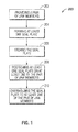
FIG. 1 is a flowchart illustrating steps for manufacturing a seal plate in accordance with an embodiment of the present disclosure; -
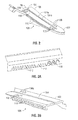
FIG. 2 is a side, perspective view of a seal plate according to an embodiment of the present disclosure and formed via the method ofFIG. 1 ; -
FIGS. 3A and 3B are perspective views of a seal plate according to an alternate embodiment of the present disclosure and formed via the method ofFIG. 1 ; -
FIG. 4 is a perspective view of a seal plate according to an alternate embodiment of the present disclosure and formed via the method ofFIG. 1 ; -
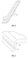
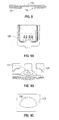
FIGS. 5A and 5B are respective cross-sectional views of a seal plate shown in a pre-formed and formed condition according to an alternate embodiment of the present disclosure and formed via the method ofFIG. 1 ; -
FIG. 6 is a perspective view of the seal plate ofFIGS. 5A and 5B ; - F1G. 7 is a perspective view of a seal plate according to an alternate embodiment of the present disclosure and formed via the method of
FIG. 1 ; -
FIG. 8 is a cross-sectional view of a laminated seal plate according to an alternate embodiment of the present disclosure and formed via the method ofFIG. 1 ; -
FIGS. 9A-9C is a seal plate including one or more points of electrical contact according to an alternate embodiment of the present disclosure and formed via the method ofFIG. 1 ; -
FIG. 10 is an area of detail of the seal plate illustrated inFIG. 1 ; -
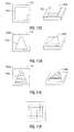
FIGS. 11A-11F are various configurations of spacers adapted for use with a seal plate formed via the method ofFIG. 1 ; -
FIG. 12 illustrates a block diagram of a system adapted for use with the method ofFIG. 1 and configured to position one of the various spacers depicted inFIGS. 11A-11F within a seal plate formed via the method ofFIG. 1 ; and -
FIGS. 13A and 13B are functional block diagrams of a method of use of the system ofFIG. 12 . - Embodiments of the presently disclosed method and system are described in detail with reference to the drawing figures wherein like reference numerals identify similar or identical elements. As used herein, the term "distal" refers to that portion which is further from the user while the term "proximal" refers to that portion which is closer to the user.
- The method and system of the present disclosure implements photolithographic processes in combination with etching processes to create specific, unique, complex geometries and/or features for seal plates used in the design of electrosurgical instruments, such as, for example, bipolar and monopolar electrosurgical devices. For example, possible features may include knife blade slots, recessed features, fine delicate features, and half etched features; all of which to be discussed in greater detail below. In addition to creating the aforementioned features, the precision of etching allows for greatly reduced tolerance stack-ups which could reduce issues with, for example, knife blade to knife slot ratios. Moreover, because the seal plates of the present disclosure are formed via suitable photolithographic and etching processes, the seal plates may be processed in lead frames that may be used in automated processes, which reduces costs associated with the aforementioned conventional manufacturing processes (e.g., stamping). Further, etch recipes associated with a given etch process, allow a user to enter practical data relating to the seal plate that may facilitate forming the seal plate during the etch process. For example, etch recipes associated with a given etch process may be tuned to have both vertical and non-vertical profiles, such as, when forming a knife slot on the seal plate.
- With reference to
FIG. 1 , a flowchart illustrating a method of manufacture for an end effector assembly that includes a pair of jaw members each including a seal plate disposed thereon and configured for use with an electrosurgical instrument, e.g., electrosurgical forceps, in accordance with an embodiment of the present disclosure is shown designated 200. - An initial step of the
method 200 includes providing a pair of jaw members (step 202) associated with an end effector adapted to connect to an electrosurgical forceps, such as, for example, a bipolar forceps. The jaw members may be formed by any suitable means, e.g., molding, casting, stamping, etc. - So as not to obscure the following disclosure with redundant information, manufacture of the seal plate is described herein as a single seal plate formed from a single sheet of material. Those skilled in the art will appreciate that a plurality of seal plates may be manufactured from a single sheet of material.
- A step of
method 200 includes forming a seal plate 102 (seestep 204, inFIG. 1 ).Seal plate 102 may be formed from any suitable material, such as, for example, from a sheet of metal. Aseal plate 102 formed according tomethod 200 is shown inFIG. 2 . During formation ofseal plate 102,seal plate 102 may be fully or partially etched (seestep 206, inFIG. 1 ). For example,seal plate 102 may be etched to include one or more types of retention features 106. In the embodiment illustrated inFIG. 2 , retention features 106 include a plurality etchedflanges 110 that extend along one of a pair ofsides 108 of theseal plate 102. In embodiments, retention features 106 may be partially etched in and/or fully etched through theseal plate 102. An example of partially etched retention features 106 is illustrated inFIG. 3A . More particularly, the partially etched retention features may be partially etchedslots 112, partially etchedcavities 114, and/or partially etchedcurved channels 116. An example of fully etched retention features 106 is illustrated inFIG. 3B . More particularly, the fully etched retention features 106 may be fully etchedapertures 118. In either of the embodiments illustrated inFIGS. 2-3B , retention features 106 may be configured to securely retain theseal plate 102 to a respective jaw member of an end effector assembly associated with an electrosurgical forceps. - A step of
method 200 includes positioning theseal plate 102 on a respective jaw member and subsequently overmolding theseal plate 102 to a respective jaw member (seesteps FIG. 1 ). In an embodiment, the photolithographic and etch processes in accordance with themethod 200 of the present disclosure may be implemented to create partial etch dams along aside 108 of theseal plate 102. More particularly, one or morepartial etch dams 116 may be disposed and/or formed along one of thesides 108 ofseal plate 102, seeFIG. 4 ,Partial etch dam 116 is configured to control the height of an overmold during the overmolding process of theseal plate 102 to a respective jaw member of the end effector assembly. More particularly, thepartial dam 116 is configured to inhibit the flow of a plastic during the overmolding process ensuring that the height of the plastic does not exceed a predetermined height on theseal plate 102 and/or the respective jaw member. Controlling and/or preventing the height of the plastic from exceeding a predetermined height on theseal plate 102 and/or a respective jaw member, e.g.,jaw member partial etch dam 116 creates aseal plate 102 having a consistent height across a length of theseal plate 102, which, in turn, provides a consistent seal across tissue and minimizes thermal spread to adjacent tissue. Experimentation on urethane coating processes confirms a relationship between seal plates having consistent (or inconsistent) seal plate heights and thermal spread. More particularly, thermal spread as a result of seal plates having consistent heights across a length of the seal plate was negligible when compared to seal plates having inconsistent heights across a length of the seal plate. - In an embodiment, the photolithographic and etching processes in accordance with the
method 200 of the present disclosure may be employed to create one or more textured patterns on theseal plate 102. More particularly, one type of textured pattern may include, for example, atextured pattern 134 having a plurality of raised dots with varying dimensions etched on a portion of aseal surface 102a of theseal plate 102, seeFIG. 2 and10 . - With reference to
FIGS. 5A and 5B ,seal plate 102 is illustrated pre-formed and formed, respectively. In an embodiment, the photolithographic and etching processes in accordance with themethod 200 of the present disclosure may be implemented to facilitate forming of theseal plate 102. More particularly, selectively and/or partially etching theseal plate 102 lightens the overall structure of theseal plate 102, which, in turn, facilitates bending of theseal plate 102 during the forming process. To this end, one or more areas of theseal plate 102 may be selectively and/or partially etched. More particularly, selectively and/or partially etchedareas 118 of theseal plate 102 may be located at predetermined locations on theseal plate 102, seeFIGS. 5A and6 . Additionally, partial etching may be implemented to createcurves 120 with small, tight radii, seeFIGS. 5B and7 , which also makes formingseal plate 102 easier. - With reference again to
FIG. 2 , in an embodiment, the photolithographic and etching processes in accordance with themethod 200 of the present disclosure may be implemented to create aknife slot 104 on theseal plate 102. More particularly, aknife slot 104 may be fully etched through theseal plate 102. The high precision that is associated with known photolithographic and etching processes, allows a manufacturer to form a fully etchedknife slot 104 with various geometries. More particularly,in embodiments,the fully etchedknife slot 104 may be defined by a pair of inner facingwalls 104a and 104b.Inner facingwalls 104aand 104b may be etched to have any suitable configuration. The precise configuration of theinner facing walls FIG. 2 , inner facing walls104a and 104b are illustrate perpendicular with respect to the seal surface 102b of theseal plate 102. In the embodiment illustrated inFIGS.5A and 5B ,inner facingwalls seal plate 102. - With reference to
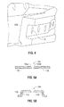
FIGS. 8-9B ,in an embodiment, the photolithographic and etching processes in accordance with themethod 200 of the present disclosure may be implemented to create selectivelyand/or partially etched areas on theseal plate 102 that are configured to provide one or more electrical points of contact on the seal plate102 such that electrosurgical energy may be provided to theseal plate 102 and/or other electrical components associated therewith. More particularly,one or more materials may be laminated together and, subsequently,selectively and/or partially etched. The materials laminated together may be conductive,partially-conductive,or non-conductive.Suitable materials may include but are not limited to stainless steel, copper, silver,and the like. - In the embodiment illustrated in
FIG.8 ,a portion of the seal plate102 includes layers ofstainless steel 122 andcopper 124 laminated together. In this embodiment,the layer ofcopper 124 is selectively etched. Etching thecopper 124 in this manner may be used to create one or moreetched areas 126 configured to receive one or more types of electrical interlaces. More particularly,an etchedarea 126 may be configured to receive integrated flex, e.g.,apolyimide flex circuit 128 that is configured to provide electrosurgical energy to theseal plate 102, seeFIG.9A . In this instance,one or more throughholes 130 may be fully etched to create electrical interconnections through dialectic material located on the polyimide flex (FIG. 9B ). Additionally,seal plate 102 may include one or more partially or fully etched areas configured to receive a bead ofsolder 132 to create one or more electrical interconnections on theseal plate 102 which may result in electrical wiring being an integral component of the seal plate 102.In addition to the foregoing,laminating layers of material together and,subsequently,etching(e.g., partially or fully) one of the layers of material may be used to create heat sinks(not explicitly shown)at specific,locations on theseal plate 102. - As noted above, in certain instances the seal plates are configured to maintain a desired gap distance. With reference to
FIGS.13A-11F ,in an embodiment, the photolithographic and etching processes in accordance with themethod 200 of the present disclosure may be implemented to create one or more different types of insulation barriers, e.g.,stop members, between seal plates associated with an end effector assembly More particularly, photolithographic and etching processes of the present disclosure may be implemented to create one or more partially or fully etched recesses orpockets 136a onseal surface 102a of the seal plate 102 (seeFIG.11A ,for example),wherein the pockets136a is configured to receive one or more types of correspondingspacers 136b (FIG.11A ). Anetched recess 136a may include an etch depth of .002 inches.Spacer 136b may be any suitable type of spacer known in the art.Spacer 136 may extend fromseal surface 102a a distance that ranges from about .005 inches to about .01 inches. In an embodiment,spacer 136b may be a ceramic spacer made from aluminum titanium carbide, commonly referred to in the art and hereinafter referred to as AlTiC). -
Etched recesses 136a andcorresponding spacers 136b may have any suitable geometric configuration and may be dimension to fit within a .030 x.030 inch area (FIG. 11B ). For example,FIG.11A illustrates an etchedrecess 136a andcorresponding spacer 136b each including a hemispherical configuration.FIG.11B illustrates an etchedrecess 138a andcorresponding spacer 138b each including a cylindrical configuration.FIG. 11C illustrates an etchedrecess 140a andcorresponding spacer 140b each including a square configuration.FIG. 11D illustrates an etchedrecess 142a and corresponding spacer 142b each including a triangular configuration.FIG.11E illustrates a plurality of etched recesses 144a andcorresponding spacers 144b in anintermittent or staggered configuration.In embodiments,any of the aforementioned etched recesses and corresponding spacers may be arranged in a grid like configuration, seeFIG. 11F for example. The combination of any of the aforementioned etched recesses, e.g.,recess 138a and spacers,e.g.,spacer 138b provides a user with the ability to manipulate how thejaw members recess 138a andcorresponding spacer 138b may be configured to force one of the jaw members, e.g., aupper jaw member 110 to roll along an axis of thespacer 138b when the upper jaw member110 and abottom jaw member 120 of an end effector assembly are moved toward each other, which, in turn,results in a more precise alignment of the upper andlower jaw members - Moreover, the combination of any of the aforementioned etched recesses, e.g.,
recess 136a and spacers, e.g.,spacer 136b increases the integrity of a bond between theseal surface 102a andspacer 136b in that thespacer 136b is encased within arecess 136b,as opposed to only being bonded to the seal surface102a of the seal plate102.The photolithographic and etching processes in accordance with themethod 200 of the present disclosure allows a manufacturer to position any of the aforementioned spacers, e.g.,spacer 136b within acorresponding pocket 136a to within a .0005 inch tolerance. - With reference now to
FIGS. 12-13B ,in an embodiment, a step of themethod 200 may include etching one or more recesses, e.g., 136a on theseal surface 102a of theseal plate 102 and positioning a spacer, e.g.,spacer 136b in the recess 136a.In this instance, anautomated system 300 is provided and includes a plurality ofmodules 400 that includes avacuum module 600, anadhesive dispersing module 700, and an optional optical module 800.Each of the foregoing modules is fully automated and in operative communication with a photolithography module 500 (configured to provide junctions previously described herein) that is also fully automated. -
Photolithography module 500 is configured to fully, partially,and/or selectively etch one ormore pockets 136b on theseal surface 102a of theseal plate 102. After the poclcets 136b have been etched into theseal surface 102a of theseal plate 102, theseal plate 102 is transferred toadhesive dispensing module 700 where a bead of adhesive 702 will be dispensed into thepocket 136b such that a spacer136a may be positioned into thepocket 136b and bonded therein. -
Vacuum module 600 is configured to raise and transfer a spacer, e.g.,spacer 136b from a loading module 900 (a loading table 900, for example) to the one ormore pockets 136a on theseal plate 102 and lower thespacer 136b within thepocket 136a on theseal plate 102. With this purpose mind, thevacuum module 600 includes one or morevacuum transfer devices 602 operatively connected to avacuum source 604.Vacuum transfer device 602 may be any suitable device that is capable of raising, transferring and lowering aspacer 136b. For example, vacuum devices typically associated with the manufacture process of disk drives, auto sunder bond, SMT automated assembly and PCB assembly may be utilized in combination withvacuum module 600. In an embodiment, the vacuum transfer device 602 (e.g., vacuum device typically utilized in the manufactureprocess PCB assembly) includes adistal end 606 configured to raise aspacer 136b (FIG.13 ) from loading table 900, transfer thespacer 136b to therecess 136a, and, subsequently, lower thespacer 136b within therecess 136a. -
Adhesive dispensing module 700 is configured to dispense a bead ofsuitable adhesive 702 into the one or more pockets 116a on theseal plate 102. In an embodiment,the adhesive dispensing module includes adevice 704 configured to heat cure the adhesive 702 after thespacer 136b has been positioned within thepocket 136a. - In an embodiment, an
optical module 800 is provided and is configured to monitor the volume of adhesive 702 dispensed within thepocket 136a, monitor alignment of thespacer 136b with respect topocket 136a and/or monitor placement of thespacer 136b within thepocket 136a. To this end,optical module 800 may include one or more types ofcamera 802 lacated at or near theadhesive dispensing module 700. -
System 300 includes one ormore microprocessors 1100 including one ormore algorithms 1200 configured to control and monitor each of the above-referenced modules during transferring and positioning of the spacers136b within thepockets 136a.System 300 employs an x-y coordinate axis system to facilitate properly aligning aspacer 136b andpocket 136a (FIG. 13A ). - In use, the
vacuum transfer device 602 ofvacuum module 600 is used to raise one of a plurality ofspacers 136b from a loading table 900 to an adhesive station1000 where theseal plate 102 is located. At a time prior to thespacer 136b arriving at theadhesive station 1000,adhesive dispensing module 700 dispenses a bead of adhesive 702 (FIG.13B ) within apocket 136a. The time the bead of adhesive 702 is dispensed will depend on such parameters as type of adhesive, cure time of adhesive,volume of adhesive, etc.Camera 802 ofoptical module 800 may be employed to ensure that thespacer 136b andpocket 136a are properly aligned. Once it is determined that the spacer136a andpocket 136b are properly aligned, thevacuum transfer device 602 may be employed to lower thespacer 136b intopocket 136a.Camera 802 ofoptical module 800 may again be employed to ensure that the spacer136b seats at a proper height abovepocket 136a (FIG. 13B ). In accordance with the present disclosure spacer136b seats at a height above thepocket 136a that ranges from about .001inches to about .006 inches. Once it is determined that thespacer 136b seats at a proper height abovepocket 136a,ultra violet heat may be applied to facilitate the curing process. - From the foregoing and with reference to the various figure drawings, those skilled in the art will appreciate that certain modifications can also be made to the present disclosure without departing from the scope of the same.
- While several embodiments of the disclosure have been shown in the drawings, it is not intended that the disclosure be limited thereto, as it is intended that the disclosure be as broad in scope as the art will allow and that the specification be read likewise.Therefore, the above description should not be construed as limiting, but merely as exemplifications of particular embodiments. Those skilled in the art will envision other modifications within the scope and spirit of the claims appended hereto.
- In the following, there is listed numbered items of the present disclosure corresponding to the claims as originally filed of the parent application,
EP 10 181 034.9 - 1. A method of manufacture for an end effector assembly,the method including:
- providing a pair of jaw members;
- forming at least one seal plate positionable on at least one of the pair of jaw members;
- etching a dam along a side of the at least one seal plate, wherein the etched dam inhibits the flow of a plastic on the at least one seal plate such that a height of the plastic with respect to the at least one seal plate during an overmolding process may be controlled;
- positioning the at least one seal plate on at least one of the pair of jaw members; and
- overmolding the seal plate to the at least one of the pair of jaw members.
- 2. A method of manufacture for an end effector assembly according to 1, wherein the step of etching is performed via a photolithographic process.
- 3. A method of manufacture for an end effector assembly according to 1 or 2, further including the step of etching a knife slot on the at least one seal plate.
- 4. A method of manufacture for an end effector assembly according to 1, 2 or 30 wherein the step of etching further includes etching a plurality of targeted retention features along the side of the at least one seal plate.
- 5. A method ofmanufacturefor an end effector assembly according to 4, wherein the plurality of targeted retention features are etched through a side of the at least one seal plate.
- 6. A method of manufacture for an end effector assembly according to 4, wherein the plurality of targeted retention features are etched partially through a side of the at leasl one seal plate.
- 7. A method of manufacture for an end effector assembly according to any one of the preceding items, wherein the step of forming at least one seal plate includes laminating at least two materials together, wherein at least one of the two materials is electrically conductive.
- 8. A method of manufacture for an end effector assembly according to 7, wherein at least one of the at least two materials is selected from stainless steel,copper and ceramic.
- 9. A method of manufacture for an end effector assembly according to any one of the preceding items, wherein the step of etching includes selectively etching copper such that heat sinks are formed at predetermined locations on the at least one seal plate.
- 10. A method of manufacture for an end effector assembly according to 9, further including the step of securing a polyimide flex circuit to the at least one seal prate, wherein the polyimide flex circuit is configured to provide electrical communication between the at least one seal plate and a source of electrosurgical energy.
- 11. A method of manufacture for an end effector assembly according to 10, wherein the step of etching includes etching at least one through hole configured to create an electrical interconnection through a dialectic material on the polyimide flex circuit.
- 12. A method of manufacture for an end effector assembly according to any one of the preceding items, wherein the step of etching includes etching at least one of a textured surface, logo,and ruler on the at least one seal plate.
Claims (12)
- A method of affixing a seal plate to a jaw member of an end effector assembly of a forceps, comprising:pre-forming at least one seal plate positionable on at least one of a pair of jaw members that collectively form the end effector assembly;etching a portion of the at least one pre-formed seal plate along a predetermined location thereof to facilitate forming thereof;bending the at least one seal plate along the etched portion thereof to form the at least one seal plate;positioning the formed seal plate on at least one of a pair of jaw members; andovermolding the seal plate to affix the seal plate to the at least one jaw member.
- A method of affixing a seal plate to a jaw member of an end effector assembly of a forceps according to claim 1, wherein the step of etching is performed via a photolithographic process.
- A method of affixing a seal plate to a jaw member of an end effector assembly of a forceps according to claim 1, wherein the step of etching further includes etching at least one recess on a seal surface of the at least one seal plate.
- A method of affixing a seal plate to a jaw member of an end effector assembly of a forceps according to claim 3, further including the step of positioning a spacer into the at least one recess.
- A method of affixing a seal plate to a jaw member of an end effector assembly of a forceps according to claim 4, wherein the spacer is made from aluminum titanium carbide.
- A method of affixing a seal plate to a jaw member of an end effector assembly of a forceps according to claim 5, wherein the at least one recess and spacer each includes one of a hemispherical, cylindrical, square and triangular configuration.
- A method of affixing a seal plate to a jaw member of an end effector assembly of a forceps according to claim 6, further including the step of arranging the at least one recess in a grid configuration.
- A method of affixing a seal plate to a jaw member of an end effector assembly of a forceps according to claim 4, further including the step of providing a vacuum module and an adhesive dispensing module.
- A method of affixing a seal plate to a jaw member of an end effector assembly of a forceps according to claim 8, further including the step of dispensing an adhesive into the at least one recess via the adhesive dispensing module.
- A method of affixing a seal plate to a jaw member of an end effector assembly of a forceps according to claim 9, wherein the step of positioning a spacer into the at least one recess is accomplished via the vacuum module.
- A method of affixing a seal plate to a jaw member of an end effector assembly of a forceps according to claim 9, further including the step of providing an optical module to monitor the amount of adhesive that is dispensed within the at least one recess.
- A method of affixing a seal plate to a jaw member of an end effector assembly of a forceps according to claim 11, further including the step of heat curing the adhesive via the adhesive dispensing module.
Applications Claiming Priority (2)
| Application Number | Priority Date | Filing Date | Title |
|---|---|---|---|
| US12/568,199 US8266783B2 (en) | 2009-09-28 | 2009-09-28 | Method and system for manufacturing electrosurgical seal plates |
| EP10181034.9A EP2301467B1 (en) | 2009-09-28 | 2010-09-28 | Method for manufacturing electrosurgical seal plates |
Related Parent Applications (3)
| Application Number | Title | Priority Date | Filing Date |
|---|---|---|---|
| EP10181034.9 Division | 2010-09-28 | ||
| EP10181034.9A Division-Into EP2301467B1 (en) | 2009-09-28 | 2010-09-28 | Method for manufacturing electrosurgical seal plates |
| EP10181034.9A Division EP2301467B1 (en) | 2009-09-28 | 2010-09-28 | Method for manufacturing electrosurgical seal plates |
Publications (2)
| Publication Number | Publication Date |
|---|---|
| EP2425793A1 true EP2425793A1 (en) | 2012-03-07 |
| EP2425793B1 EP2425793B1 (en) | 2014-01-15 |
Family
ID=43416846
Family Applications (3)
| Application Number | Title | Priority Date | Filing Date |
|---|---|---|---|
| EP10181034.9A Not-in-force EP2301467B1 (en) | 2009-09-28 | 2010-09-28 | Method for manufacturing electrosurgical seal plates |
| EP11184307.4A Active EP2425793B1 (en) | 2009-09-28 | 2010-09-28 | Method for manufacturing electrosurgical seal plates |
| EP14150294.8A Not-in-force EP2719352B1 (en) | 2009-09-28 | 2010-09-28 | Method for manufacturing electrosurgical seal plates |
Family Applications Before (1)
| Application Number | Title | Priority Date | Filing Date |
|---|---|---|---|
| EP10181034.9A Not-in-force EP2301467B1 (en) | 2009-09-28 | 2010-09-28 | Method for manufacturing electrosurgical seal plates |
Family Applications After (1)
| Application Number | Title | Priority Date | Filing Date |
|---|---|---|---|
| EP14150294.8A Not-in-force EP2719352B1 (en) | 2009-09-28 | 2010-09-28 | Method for manufacturing electrosurgical seal plates |
Country Status (2)
| Country | Link |
|---|---|
| US (1) | US8266783B2 (en) |
| EP (3) | EP2301467B1 (en) |
Families Citing this family (104)
| Publication number | Priority date | Publication date | Assignee | Title |
|---|---|---|---|---|
| US7364577B2 (en) | 2002-02-11 | 2008-04-29 | Sherwood Services Ag | Vessel sealing system |
| JP4499992B2 (en) | 2001-04-06 | 2010-07-14 | コヴィディエン アクチェンゲゼルシャフト | Vascular sealing machine and splitting machine having non-conductive stop member |
| US7931649B2 (en) | 2002-10-04 | 2011-04-26 | Tyco Healthcare Group Lp | Vessel sealing instrument with electrical cutting mechanism |
| US7276068B2 (en) * | 2002-10-04 | 2007-10-02 | Sherwood Services Ag | Vessel sealing instrument with electrical cutting mechanism |
| US7799026B2 (en) | 2002-11-14 | 2010-09-21 | Covidien Ag | Compressible jaw configuration with bipolar RF output electrodes for soft tissue fusion |
| US9848938B2 (en) | 2003-11-13 | 2017-12-26 | Covidien Ag | Compressible jaw configuration with bipolar RF output electrodes for soft tissue fusion |
| US7367976B2 (en) | 2003-11-17 | 2008-05-06 | Sherwood Services Ag | Bipolar forceps having monopolar extension |
| US7131970B2 (en) | 2003-11-19 | 2006-11-07 | Sherwood Services Ag | Open vessel sealing instrument with cutting mechanism |
| US7909823B2 (en) | 2005-01-14 | 2011-03-22 | Covidien Ag | Open vessel sealing instrument |
| US7628791B2 (en) | 2005-08-19 | 2009-12-08 | Covidien Ag | Single action tissue sealer |
| US7722607B2 (en) | 2005-09-30 | 2010-05-25 | Covidien Ag | In-line vessel sealer and divider |
| CA2561034C (en) | 2005-09-30 | 2014-12-09 | Sherwood Services Ag | Flexible endoscopic catheter with an end effector for coagulating and transfecting tissue |
| US7922953B2 (en) | 2005-09-30 | 2011-04-12 | Covidien Ag | Method for manufacturing an end effector assembly |
| US8475453B2 (en) | 2006-10-06 | 2013-07-02 | Covidien Lp | Endoscopic vessel sealer and divider having a flexible articulating shaft |
| WO2009005850A1 (en) * | 2007-06-29 | 2009-01-08 | Tyco Healthcare Group, Lp | Method and system for monitoring tissue during an electrosurgical procedure |
| US8357158B2 (en) | 2008-04-22 | 2013-01-22 | Covidien Lp | Jaw closure detection system |
| US8142473B2 (en) | 2008-10-03 | 2012-03-27 | Tyco Healthcare Group Lp | Method of transferring rotational motion in an articulating surgical instrument |
| US8016827B2 (en) | 2008-10-09 | 2011-09-13 | Tyco Healthcare Group Lp | Apparatus, system, and method for performing an electrosurgical procedure |
| US8114122B2 (en) | 2009-01-13 | 2012-02-14 | Tyco Healthcare Group Lp | Apparatus, system, and method for performing an electrosurgical procedure |
| US8187273B2 (en) | 2009-05-07 | 2012-05-29 | Tyco Healthcare Group Lp | Apparatus, system, and method for performing an electrosurgical procedure |
| US8246618B2 (en) | 2009-07-08 | 2012-08-21 | Tyco Healthcare Group Lp | Electrosurgical jaws with offset knife |
| US8968358B2 (en) | 2009-08-05 | 2015-03-03 | Covidien Lp | Blunt tissue dissection surgical instrument jaw designs |
| US8357159B2 (en) | 2009-09-03 | 2013-01-22 | Covidien Lp | Open vessel sealing instrument with pivot assembly |
| US8568412B2 (en) * | 2009-09-09 | 2013-10-29 | Covidien Lp | Apparatus and method of controlling cutting blade travel through the use of etched features |
| US8439911B2 (en) | 2009-09-09 | 2013-05-14 | Coviden Lp | Compact jaw including through bore pivot pin |
| US8133254B2 (en) | 2009-09-18 | 2012-03-13 | Tyco Healthcare Group Lp | In vivo attachable and detachable end effector assembly and laparoscopic surgical instrument and methods therefor |
| US8112871B2 (en) | 2009-09-28 | 2012-02-14 | Tyco Healthcare Group Lp | Method for manufacturing electrosurgical seal plates |
| US8343151B2 (en) * | 2009-10-09 | 2013-01-01 | Covidien Lp | Vessel sealer and divider with captured cutting element |
| US8480671B2 (en) | 2010-01-22 | 2013-07-09 | Covidien Lp | Compact jaw including split pivot pin |
| US8858553B2 (en) * | 2010-01-29 | 2014-10-14 | Covidien Lp | Dielectric jaw insert for electrosurgical end effector |
| US8597295B2 (en) | 2010-04-12 | 2013-12-03 | Covidien Lp | Surgical instrument with non-contact electrical coupling |
| US8623018B2 (en) | 2010-04-13 | 2014-01-07 | Covidien Lp | Sealing plate temperature control |
| US8439913B2 (en) | 2010-04-29 | 2013-05-14 | Covidien Lp | Pressure sensing sealing plate |
| US10265118B2 (en) | 2010-05-04 | 2019-04-23 | Covidien Lp | Pinion blade drive mechanism for a laparoscopic vessel dissector |
| US8672939B2 (en) | 2010-06-01 | 2014-03-18 | Covidien Lp | Surgical device for performing an electrosurgical procedure |
| US8469991B2 (en) | 2010-06-02 | 2013-06-25 | Covidien Lp | Apparatus for performing an electrosurgical procedure |
| US8409247B2 (en) | 2010-06-02 | 2013-04-02 | Covidien Lp | Apparatus for performing an electrosurgical procedure |
| US8491625B2 (en) | 2010-06-02 | 2013-07-23 | Covidien Lp | Apparatus for performing an electrosurgical procedure |
| US8430877B2 (en) | 2010-06-02 | 2013-04-30 | Covidien Lp | Apparatus for performing an electrosurgical procedure |
| US8540749B2 (en) | 2010-06-02 | 2013-09-24 | Covidien Lp | Apparatus for performing an electrosurgical procedure |
| US8491626B2 (en) | 2010-06-02 | 2013-07-23 | Covidien Lp | Apparatus for performing an electrosurgical procedure |
| US8469992B2 (en) | 2010-06-02 | 2013-06-25 | Covidien Lp | Apparatus for performing an electrosurgical procedure |
| US8585736B2 (en) | 2010-06-02 | 2013-11-19 | Covidien Lp | Apparatus for performing an electrosurgical procedure |
| US8409246B2 (en) | 2010-06-02 | 2013-04-02 | Covidien Lp | Apparatus for performing an electrosurgical procedure |
| US8491624B2 (en) | 2010-06-02 | 2013-07-23 | Covidien Lp | Apparatus for performing an electrosurgical procedure |
| US8647343B2 (en) | 2010-06-23 | 2014-02-11 | Covidien Lp | Surgical forceps for sealing and dividing tissue |
| US9028495B2 (en) | 2010-06-23 | 2015-05-12 | Covidien Lp | Surgical instrument with a separable coaxial joint |
| US8795269B2 (en) | 2010-07-26 | 2014-08-05 | Covidien Lp | Rotary tissue sealer and divider |
| US8814864B2 (en) | 2010-08-23 | 2014-08-26 | Covidien Lp | Method of manufacturing tissue sealing electrodes |
| US9005200B2 (en) | 2010-09-30 | 2015-04-14 | Covidien Lp | Vessel sealing instrument |
| US9017372B2 (en) | 2010-10-01 | 2015-04-28 | Covidien Lp | Blade deployment mechanisms for surgical forceps |
| US9113940B2 (en) | 2011-01-14 | 2015-08-25 | Covidien Lp | Trigger lockout and kickback mechanism for surgical instruments |
| US9844384B2 (en) | 2011-07-11 | 2017-12-19 | Covidien Lp | Stand alone energy-based tissue clips |
| US9028492B2 (en) * | 2011-08-18 | 2015-05-12 | Covidien Lp | Surgical instruments with removable components |
| USD680220S1 (en) | 2012-01-12 | 2013-04-16 | Coviden IP | Slider handle for laparoscopic device |
| US9011435B2 (en) | 2012-02-24 | 2015-04-21 | Covidien Lp | Method for manufacturing vessel sealing instrument with reduced thermal spread |
| US8887373B2 (en) | 2012-02-24 | 2014-11-18 | Covidien Lp | Vessel sealing instrument with reduced thermal spread and method of manufacture therefor |
| US9192421B2 (en) | 2012-07-24 | 2015-11-24 | Covidien Lp | Blade lockout mechanism for surgical forceps |
| ITFI20120233A1 (en) * | 2012-10-29 | 2014-04-30 | Esanastri S R L | MICRO-EXPLORATION DEVICE OF PLASTIC OR PAPER FILMS WITH ONE OR MORE LAYERS OF SELF-ADHESIVE, BIADESIVIZED OR ELECTROSTATIC MATCHED WITH AN NON-STICK SUPPORT LINER |
| US9713491B2 (en) | 2013-02-19 | 2017-07-25 | Covidien Lp | Method for manufacturing an electrode assembly configured for use with an electrosurigcal instrument |
| US9649151B2 (en) * | 2013-05-31 | 2017-05-16 | Covidien Lp | End effector assemblies and methods of manufacturing end effector assemblies for treating and/or cutting tissue |
| WO2015017989A1 (en) | 2013-08-07 | 2015-02-12 | Covidien Lp | Bipolar surgical instrument |
| KR102134566B1 (en) | 2013-08-07 | 2020-07-17 | 코비디엔 엘피 | Bipolar surgical instrument |
| WO2015017995A1 (en) | 2013-08-07 | 2015-02-12 | Covidien Lp | Bipolar surgical instrument with tissue stop |
| US9687295B2 (en) * | 2014-04-17 | 2017-06-27 | Covidien Lp | Methods of manufacturing a pair of jaw members of an end-effector assembly for a surgical instrument |
| US20150324317A1 (en) | 2014-05-07 | 2015-11-12 | Covidien Lp | Authentication and information system for reusable surgical instruments |
| EP2982325B1 (en) * | 2014-08-04 | 2020-03-18 | Erbe Elektromedizin GmbH | Method for producing a branch and surgical instrument with a tool having branches |
| US20160038220A1 (en) | 2014-08-11 | 2016-02-11 | Covidien Lp | Surgical instruments and methods for performing tonsillectomy and adenoidectomy procedures |
| US10478243B2 (en) | 2014-08-11 | 2019-11-19 | Covidien Lp | Surgical instruments and methods for performing tonsillectomy and adenoidectomy procedures |
| US10231777B2 (en) | 2014-08-26 | 2019-03-19 | Covidien Lp | Methods of manufacturing jaw members of an end-effector assembly for a surgical instrument |
| US10813685B2 (en) | 2014-09-25 | 2020-10-27 | Covidien Lp | Single-handed operable surgical instrument including loop electrode with integrated pad electrode |
| GB2534147B (en) * | 2015-01-14 | 2018-11-14 | Gyrus Medical Ltd | Manufacturing electrosurgical instruments |
| US10624662B2 (en) | 2015-05-22 | 2020-04-21 | Covidien Lp | Surgical instruments and methods for performing tonsillectomy, adenoidectomy, and other surgical procedures |
| US9918781B2 (en) | 2015-05-22 | 2018-03-20 | Covidien Lp | Surgical instruments and methods for performing tonsillectomy, adenoidectomy, and other surgical procedures |
| US9918780B2 (en) | 2015-05-22 | 2018-03-20 | Covidien Lp | Surgical instruments and methods for performing tonsillectomy, adenoidectomy, and other surgical procedures |
| US9918779B2 (en) | 2015-05-22 | 2018-03-20 | Covidien Lp | Surgical instruments and methods for performing tonsillectomy, adenoidectomy, and other surgical procedures |
| US10828084B2 (en) | 2015-05-22 | 2020-11-10 | Covidien Lp | Surgical instruments and methods for performing tonsillectomy, adenoidectomy, and other surgical procedures |
| US10219818B2 (en) | 2015-07-24 | 2019-03-05 | Covidien Lp | Shaft-based surgical forceps and method of manufacturing the same |
| US10987159B2 (en) | 2015-08-26 | 2021-04-27 | Covidien Lp | Electrosurgical end effector assemblies and electrosurgical forceps configured to reduce thermal spread |
| US10213250B2 (en) | 2015-11-05 | 2019-02-26 | Covidien Lp | Deployment and safety mechanisms for surgical instruments |
| US10426543B2 (en) | 2016-01-23 | 2019-10-01 | Covidien Lp | Knife trigger for vessel sealer |
| US10098689B2 (en) | 2016-02-24 | 2018-10-16 | Covidien Lp | Methods of manufacturing jaw members of surgical forceps |
| US10682154B2 (en) | 2016-08-02 | 2020-06-16 | Covidien Lp | Cutting mechanisms for surgical end effector assemblies, instruments, and systems |
| US10631887B2 (en) | 2016-08-15 | 2020-04-28 | Covidien Lp | Electrosurgical forceps for video assisted thoracoscopic surgery and other surgical procedures |
| US11272947B2 (en) | 2016-11-17 | 2022-03-15 | Covidien Lp | Surgical instruments for performing tonsillectomy, adenoidectomy, and other surgical procedures |
| US11007003B2 (en) * | 2016-11-17 | 2021-05-18 | Covidien Lp | Surgical instruments and methods of manufacturing surgical instruments for performing tonsillectomy, adenoidectomy, and other surgical procedures |
| US10639093B2 (en) | 2016-12-01 | 2020-05-05 | Covidien Lp | Surgical instrument including a wire guide |
| US10492852B2 (en) | 2017-02-27 | 2019-12-03 | Covidien Lp | Wire guide for surgical instruments and surgical instruments including a wire guide |
| US11172980B2 (en) | 2017-05-12 | 2021-11-16 | Covidien Lp | Electrosurgical forceps for grasping, treating, and/or dividing tissue |
| US10973567B2 (en) | 2017-05-12 | 2021-04-13 | Covidien Lp | Electrosurgical forceps for grasping, treating, and/or dividing tissue |
| USD854149S1 (en) | 2017-06-08 | 2019-07-16 | Covidien Lp | End effector for open vessel sealer |
| USD854684S1 (en) | 2017-06-08 | 2019-07-23 | Covidien Lp | Open vessel sealer with mechanical cutter |
| USD843574S1 (en) | 2017-06-08 | 2019-03-19 | Covidien Lp | Knife for open vessel sealer |
| US11123133B2 (en) | 2018-04-24 | 2021-09-21 | Covidien Lp | Method of reprocessing a surgical instrument |
| US11376062B2 (en) | 2018-10-12 | 2022-07-05 | Covidien Lp | Electrosurgical forceps |
| US11471211B2 (en) | 2018-10-12 | 2022-10-18 | Covidien Lp | Electrosurgical forceps |
| US11350982B2 (en) | 2018-12-05 | 2022-06-07 | Covidien Lp | Electrosurgical forceps |
| US11026710B2 (en) | 2019-01-10 | 2021-06-08 | Covidien Lp | Surgical instruments and methods of manufacturing surgical instruments for performing tonsillectomy, adenoidectomy, and other surgical procedures |
| US11523861B2 (en) | 2019-03-22 | 2022-12-13 | Covidien Lp | Methods for manufacturing a jaw assembly for an electrosurgical forceps |
| US11259864B2 (en) | 2019-06-06 | 2022-03-01 | Covidien Lp | Surgical instrument with enhanced trigger |
| US11877790B2 (en) | 2020-01-07 | 2024-01-23 | Covidien Lp | Surgical forceps having jaw members |
| US11622804B2 (en) | 2020-03-16 | 2023-04-11 | Covidien Lp | Forceps with linear trigger mechanism |
| US11844562B2 (en) | 2020-03-23 | 2023-12-19 | Covidien Lp | Electrosurgical forceps for grasping, treating, and/or dividing tissue |
| US11660109B2 (en) | 2020-09-08 | 2023-05-30 | Covidien Lp | Cutting elements for surgical instruments such as for use in robotic surgical systems |
Citations (4)
| Publication number | Priority date | Publication date | Assignee | Title |
|---|---|---|---|---|
| US20060271038A1 (en) * | 2002-10-04 | 2006-11-30 | Sherwood Services Ag | Vessel sealing instrument with electrical cutting mechanism |
| EP1958583A2 (en) * | 2007-02-14 | 2008-08-20 | Tyco Healthcare Group, LP | Vessel sealing instrument with electrical cutting mechanism |
| US20090012520A1 (en) * | 2006-01-24 | 2009-01-08 | Tyco Healthcare Group Lp | Vessel Sealer and Divider for Large Tissue Structures |
| US20090209960A1 (en) * | 2008-02-14 | 2009-08-20 | Tyco Healthcare Group Lp | End Effector Assembly for Electrosurgical Device |
Family Cites Families (70)
| Publication number | Priority date | Publication date | Assignee | Title |
|---|---|---|---|---|
| GB623316A (en) | 1947-04-29 | 1949-05-16 | Thomas Wallace Parker | Improvements in and relating to building units |
| SU401367A1 (en) | 1971-10-05 | 1973-10-12 | Тернопольский государственный медицинский институт | BIAKTIVNYE ELECTRO SURGICAL INSTRUMENT |
| DE2415263A1 (en) | 1974-03-29 | 1975-10-02 | Aesculap Werke Ag | Surgical H.F. coagulation probe has electrode tongs - with exposed ends of insulated conductors forming tong-jaws |
| DE7418576U (en) | 1974-05-30 | 1974-09-12 | Richard Wolf Gmbh | Catheter with a loop that can be put under tension |
| DE2514501A1 (en) | 1975-04-03 | 1976-10-21 | Karl Storz | Bipolar coagulation instrument for endoscopes - has two high frequency electrodes looped over central insulating piece |
| FR2315286A2 (en) | 1975-06-26 | 1977-01-21 | Lamidey Marcel | H.F. blood coagulating dissecting forceps - with adjustable stops to vary clamping space and circuit making contacts |
| DE3490633T (en) | 1984-01-30 | 1985-12-12 | Char'kovskaja oblastnaja kliničeskaja bol'nica, Char'kov | Bipolar electrosurgical device |
| US4657016A (en) | 1984-08-20 | 1987-04-14 | Garito Jon C | Electrosurgical handpiece for blades, needles and forceps |
| DE8712328U1 (en) | 1987-09-11 | 1988-02-18 | Jakoubek, Franz, 7201 Emmingen-Liptingen, De | |
| GB2213416B (en) | 1987-12-11 | 1991-12-18 | Stanley Works Ltd | Blade-carriers for retractable-blade knives |
| GB8801177D0 (en) | 1988-01-20 | 1988-02-17 | Goble N M | Diathermy unit |
| JP2806511B2 (en) | 1990-07-31 | 1998-09-30 | 松下電工株式会社 | Manufacturing method of sintered alloy |
| US5282799A (en) | 1990-08-24 | 1994-02-01 | Everest Medical Corporation | Bipolar electrosurgical scalpel with paired loop electrodes |
| US5190541A (en) | 1990-10-17 | 1993-03-02 | Boston Scientific Corporation | Surgical instrument and method |
| JP2951418B2 (en) | 1991-02-08 | 1999-09-20 | トキコ株式会社 | Sample liquid component analyzer |
| US5683366A (en) | 1992-01-07 | 1997-11-04 | Arthrocare Corporation | System and method for electrosurgical tissue canalization |
| JPH05258641A (en) | 1992-03-16 | 1993-10-08 | Matsushita Electric Ind Co Ltd | Panel switch |
| US5562720A (en) | 1992-05-01 | 1996-10-08 | Vesta Medical, Inc. | Bipolar/monopolar endometrial ablation device and method |
| CA2104423A1 (en) | 1992-08-24 | 1994-02-25 | Boris Zvenyatsky | Handle for endoscopic instruments and jaw structure |
| DE4303882C2 (en) | 1993-02-10 | 1995-02-09 | Kernforschungsz Karlsruhe | Combination instrument for separation and coagulation for minimally invasive surgery |
| GB9309142D0 (en) | 1993-05-04 | 1993-06-16 | Gyrus Medical Ltd | Laparoscopic instrument |
| US5512721A (en) | 1993-09-28 | 1996-04-30 | Unisurge, Inc. | Autoclavable electrical switch assembly for use with a medical device and medical device using the same |
| GB9322464D0 (en) | 1993-11-01 | 1993-12-22 | Gyrus Medical Ltd | Electrosurgical apparatus |
| DE4403252A1 (en) | 1994-02-03 | 1995-08-10 | Michael Hauser | Instrument shaft for min. invasive surgery |
| US5505730A (en) | 1994-06-24 | 1996-04-09 | Stuart D. Edwards | Thin layer ablation apparatus |
| GB9413070D0 (en) | 1994-06-29 | 1994-08-17 | Gyrus Medical Ltd | Electrosurgical apparatus |
| GB9425781D0 (en) | 1994-12-21 | 1995-02-22 | Gyrus Medical Ltd | Electrosurgical instrument |
| US6602248B1 (en) | 1995-06-07 | 2003-08-05 | Arthro Care Corp. | Methods for repairing damaged intervertebral discs |
| DE19515914C1 (en) | 1995-05-02 | 1996-07-25 | Aesculap Ag | Tong or scissor-shaped surgical instrument |
| US7179255B2 (en) | 1995-06-07 | 2007-02-20 | Arthrocare Corporation | Methods for targeted electrosurgery on contained herniated discs |
| US6293942B1 (en) | 1995-06-23 | 2001-09-25 | Gyrus Medical Limited | Electrosurgical generator method |
| US5792137A (en) | 1995-10-27 | 1998-08-11 | Lacar Microsystems, Inc. | Coagulating microsystem |
| US6126656A (en) | 1996-01-30 | 2000-10-03 | Utah Medical Products, Inc. | Electrosurgical cutting device |
| DE19608716C1 (en) | 1996-03-06 | 1997-04-17 | Aesculap Ag | Bipolar surgical holding instrument |
| US6620155B2 (en) | 1996-07-16 | 2003-09-16 | Arthrocare Corp. | System and methods for electrosurgical tissue contraction within the spine |
| DE29616210U1 (en) | 1996-09-18 | 1996-11-14 | Winter & Ibe Olympus | Handle for surgical instruments |
| US5923475A (en) | 1996-11-27 | 1999-07-13 | Eastman Kodak Company | Laser printer using a fly's eye integrator |
| US5925043A (en) | 1997-04-30 | 1999-07-20 | Medquest Products, Inc. | Electrosurgical electrode with a conductive, non-stick coating |
| DE19738457B4 (en) | 1997-09-03 | 2009-01-02 | Celon Ag Medical Instruments | Method and device for in vivo deep coagulation of biological tissue volumes while sparing the tissue surface with high frequency alternating current |
| DE19751108A1 (en) | 1997-11-18 | 1999-05-20 | Beger Frank Michael Dipl Desig | Electrosurgical operation tool, especially for diathermy |
| EP0923907A1 (en) | 1997-12-19 | 1999-06-23 | Gyrus Medical Limited | An electrosurgical instrument |
| US6106542A (en) | 1998-01-23 | 2000-08-22 | Microsurgical Laboratories, Inc. | Surgical forceps |
| US6049650A (en) * | 1998-04-17 | 2000-04-11 | Seagate Technology, Inc. | Structure for micro-machine optical tooling and method for making and using |
| US6508815B1 (en) | 1998-05-08 | 2003-01-21 | Novacept | Radio-frequency generator for powering an ablation device |
| US6585735B1 (en) * | 1998-10-23 | 2003-07-01 | Sherwood Services Ag | Endoscopic bipolar electrosurgical forceps |
| GB9911954D0 (en) | 1999-05-21 | 1999-07-21 | Gyrus Medical Ltd | Electrosurgery system and instrument |
| GB9911956D0 (en) | 1999-05-21 | 1999-07-21 | Gyrus Medical Ltd | Electrosurgery system and method |
| GB9912625D0 (en) | 1999-05-28 | 1999-07-28 | Gyrus Medical Ltd | An electrosurgical generator and system |
| GB9912627D0 (en) | 1999-05-28 | 1999-07-28 | Gyrus Medical Ltd | An electrosurgical instrument |
| GB9913652D0 (en) | 1999-06-11 | 1999-08-11 | Gyrus Medical Ltd | An electrosurgical generator |
| JP4233742B2 (en) | 1999-10-05 | 2009-03-04 | エシコン・エンド−サージェリィ・インコーポレイテッド | Connecting curved clamp arms and tissue pads used with ultrasonic surgical instruments |
| JP2001126225A (en) * | 1999-10-21 | 2001-05-11 | Tdk Corp | Method for manufacturing magnetic head slider, method for fixing bar and curing agent |
| US6953461B2 (en) | 2002-05-16 | 2005-10-11 | Tissuelink Medical, Inc. | Fluid-assisted medical devices, systems and methods |
| US6558385B1 (en) | 2000-09-22 | 2003-05-06 | Tissuelink Medical, Inc. | Fluid-assisted medical device |
| DE10027727C1 (en) | 2000-06-03 | 2001-12-06 | Aesculap Ag & Co Kg | Scissors-shaped or forceps-shaped surgical instrument |
| US6464702B2 (en) * | 2001-01-24 | 2002-10-15 | Ethicon, Inc. | Electrosurgical instrument with closing tube for conducting RF energy and moving jaws |
| US7083618B2 (en) * | 2001-04-06 | 2006-08-01 | Sherwood Services Ag | Vessel sealer and divider |
| JP2005501609A (en) | 2001-09-05 | 2005-01-20 | ティシューリンク・メディカル・インコーポレーテッド | Fluid-assisted medical device, fluid supply system and controller and method for the device |
| US20040030330A1 (en) | 2002-04-18 | 2004-02-12 | Brassell James L. | Electrosurgery systems |
| ATE444722T1 (en) | 2002-11-27 | 2009-10-15 | Pulmonx Corp | INTRODUCTION SET FOR IMPLANTABLE BRONCHIAL ISOLATION DEVICES |
| US7909820B2 (en) | 2003-03-06 | 2011-03-22 | Salient Surgical Technologies, Inc. | Electrosurgical generator and bipolar electrosurgical device adaptors |
| US7150097B2 (en) | 2003-06-13 | 2006-12-19 | Sherwood Services Ag | Method of manufacturing jaw assembly for vessel sealer and divider |
| US7686804B2 (en) * | 2005-01-14 | 2010-03-30 | Covidien Ag | Vessel sealer and divider with rotating sealer and cutter |
| US7491202B2 (en) * | 2005-03-31 | 2009-02-17 | Covidien Ag | Electrosurgical forceps with slow closure sealing plates and method of sealing tissue |
| US20060283093A1 (en) | 2005-06-15 | 2006-12-21 | Ivan Petrovic | Planarization composition |
| US7922953B2 (en) * | 2005-09-30 | 2011-04-12 | Covidien Ag | Method for manufacturing an end effector assembly |
| US7846158B2 (en) | 2006-05-05 | 2010-12-07 | Covidien Ag | Apparatus and method for electrode thermosurgery |
| US7877852B2 (en) | 2007-09-20 | 2011-02-01 | Tyco Healthcare Group Lp | Method of manufacturing an end effector assembly for sealing tissue |
| US20090254081A1 (en) | 2008-04-08 | 2009-10-08 | Tyco Electronics Corporation | System and method for surgical jaw assembly |
| US8112871B2 (en) * | 2009-09-28 | 2012-02-14 | Tyco Healthcare Group Lp | Method for manufacturing electrosurgical seal plates |
-
2009
- 2009-09-28 US US12/568,199 patent/US8266783B2/en active Active
-
2010
- 2010-09-28 EP EP10181034.9A patent/EP2301467B1/en not_active Not-in-force
- 2010-09-28 EP EP11184307.4A patent/EP2425793B1/en active Active
- 2010-09-28 EP EP14150294.8A patent/EP2719352B1/en not_active Not-in-force
Patent Citations (4)
| Publication number | Priority date | Publication date | Assignee | Title |
|---|---|---|---|---|
| US20060271038A1 (en) * | 2002-10-04 | 2006-11-30 | Sherwood Services Ag | Vessel sealing instrument with electrical cutting mechanism |
| US20090012520A1 (en) * | 2006-01-24 | 2009-01-08 | Tyco Healthcare Group Lp | Vessel Sealer and Divider for Large Tissue Structures |
| EP1958583A2 (en) * | 2007-02-14 | 2008-08-20 | Tyco Healthcare Group, LP | Vessel sealing instrument with electrical cutting mechanism |
| US20090209960A1 (en) * | 2008-02-14 | 2009-08-20 | Tyco Healthcare Group Lp | End Effector Assembly for Electrosurgical Device |
Also Published As
| Publication number | Publication date |
|---|---|
| US20110072638A1 (en) | 2011-03-31 |
| EP2301467A1 (en) | 2011-03-30 |
| EP2301467B1 (en) | 2014-02-19 |
| US8266783B2 (en) | 2012-09-18 |
| EP2425793B1 (en) | 2014-01-15 |
| EP2719352A1 (en) | 2014-04-16 |
| EP2719352B1 (en) | 2016-01-20 |
Similar Documents
| Publication | Publication Date | Title |
|---|---|---|
| US11490955B2 (en) | Electrosurgical seal plates | |
| EP2425793B1 (en) | Method for manufacturing electrosurgical seal plates | |
| JP6834000B2 (en) | Flexible connector | |
| US4891014A (en) | Method of forming contact bumps in contact pads | |
| US7829977B2 (en) | Low temperature co-fired ceramics substrate and semiconductor package | |
| US20100133672A1 (en) | Dual-sided substate integrated circuit package including a leadframe having leads with increased thickness | |
| US5253415A (en) | Method of making an integrated circuit substrate lead assembly | |
| US20050125997A1 (en) | Method and device for through-hole plating of substrates and printed circuit boards | |
| US6309910B1 (en) | Microelectronic components with frangible lead sections | |
| US6274822B1 (en) | Manufacture of semiconductor connection components with frangible lead sections | |
| EP1792870A2 (en) | Double-sided etching method using embedded alignment mark | |
| US6218213B1 (en) | Microelectronic components with frangible lead sections | |
| Peterson et al. | Continuing Challenges in LTCC. | |
| TW571426B (en) | Manufacturing method of non-optical etched thin film resistor | |
| JPH11168038A (en) | Method for forming constituent element of ceramic sheet base | |
| EP2675253A1 (en) | Flexible-rigid circuit board composite and method for producing a flexible-rigid circuit board composite | |
| Peterson et al. | Challenges in LTCC. | |
| WO2020074151A1 (en) | Flipped-conductor-patch lamination for ultra fine-line substrate creation | |
| JPH11337574A (en) | Manufacture of probe unit | |
| KR20080114097A (en) | Method for producing probe card | |
| JPH10308583A (en) | Manufacture of ceramic multilayered board and manufacturing equipment |
Legal Events
| Date | Code | Title | Description |
|---|---|---|---|
| AC | Divisional application: reference to earlier application |
Ref document number: 2301467 Country of ref document: EP Kind code of ref document: P |
|
| AK | Designated contracting states |
Kind code of ref document: A1 Designated state(s): AL AT BE BG CH CY CZ DE DK EE ES FI FR GB GR HR HU IE IS IT LI LT LU LV MC MK MT NL NO PL PT RO SE SI SK SM TR |
|
| AX | Request for extension of the european patent |
Extension state: BA ME RS |
|
| PUAI | Public reference made under article 153(3) epc to a published international application that has entered the european phase |
Free format text: ORIGINAL CODE: 0009012 |
|
| 17P | Request for examination filed |
Effective date: 20120516 |
|
| RAP1 | Party data changed (applicant data changed or rights of an application transferred) |
Owner name: COVIDIEN LP |
|
| GRAP | Despatch of communication of intention to grant a patent |
Free format text: ORIGINAL CODE: EPIDOSNIGR1 |
|
| INTG | Intention to grant announced |
Effective date: 20130827 |
|
| GRAS | Grant fee paid |
Free format text: ORIGINAL CODE: EPIDOSNIGR3 |
|
| GRAA | (expected) grant |
Free format text: ORIGINAL CODE: 0009210 |
|
| AC | Divisional application: reference to earlier application |
Ref document number: 2301467 Country of ref document: EP Kind code of ref document: P |
|
| AK | Designated contracting states |
Kind code of ref document: B1 Designated state(s): AL AT BE BG CH CY CZ DE DK EE ES FI FR GB GR HR HU IE IS IT LI LT LU LV MC MK MT NL NO PL PT RO SE SI SK SM TR |
|
| REG | Reference to a national code |
Ref country code: CH Ref legal event code: EP Ref country code: GB Ref legal event code: FG4D |
|
| REG | Reference to a national code |
Ref country code: AT Ref legal event code: REF Ref document number: 649427 Country of ref document: AT Kind code of ref document: T Effective date: 20140215 |
|
| REG | Reference to a national code |
Ref country code: IE Ref legal event code: FG4D |
|
| REG | Reference to a national code |
Ref country code: DE Ref legal event code: R096 Ref document number: 602010013221 Country of ref document: DE Effective date: 20140306 |
|
| REG | Reference to a national code |
Ref country code: NL Ref legal event code: VDEP Effective date: 20140115 |
|
| REG | Reference to a national code |
Ref country code: AT Ref legal event code: MK05 Ref document number: 649427 Country of ref document: AT Kind code of ref document: T Effective date: 20140115 |
|
| REG | Reference to a national code |
Ref country code: LT Ref legal event code: MG4D |
|
| PG25 | Lapsed in a contracting state [announced via postgrant information from national office to epo] |
Ref country code: LT Free format text: LAPSE BECAUSE OF FAILURE TO SUBMIT A TRANSLATION OF THE DESCRIPTION OR TO PAY THE FEE WITHIN THE PRESCRIBED TIME-LIMIT Effective date: 20140115 Ref country code: NO Free format text: LAPSE BECAUSE OF FAILURE TO SUBMIT A TRANSLATION OF THE DESCRIPTION OR TO PAY THE FEE WITHIN THE PRESCRIBED TIME-LIMIT Effective date: 20140415 Ref country code: IS Free format text: LAPSE BECAUSE OF FAILURE TO SUBMIT A TRANSLATION OF THE DESCRIPTION OR TO PAY THE FEE WITHIN THE PRESCRIBED TIME-LIMIT Effective date: 20140515 |
|
| PG25 | Lapsed in a contracting state [announced via postgrant information from national office to epo] |
Ref country code: SE Free format text: LAPSE BECAUSE OF FAILURE TO SUBMIT A TRANSLATION OF THE DESCRIPTION OR TO PAY THE FEE WITHIN THE PRESCRIBED TIME-LIMIT Effective date: 20140115 Ref country code: ES Free format text: LAPSE BECAUSE OF FAILURE TO SUBMIT A TRANSLATION OF THE DESCRIPTION OR TO PAY THE FEE WITHIN THE PRESCRIBED TIME-LIMIT Effective date: 20140115 Ref country code: NL Free format text: LAPSE BECAUSE OF FAILURE TO SUBMIT A TRANSLATION OF THE DESCRIPTION OR TO PAY THE FEE WITHIN THE PRESCRIBED TIME-LIMIT Effective date: 20140115 Ref country code: FI Free format text: LAPSE BECAUSE OF FAILURE TO SUBMIT A TRANSLATION OF THE DESCRIPTION OR TO PAY THE FEE WITHIN THE PRESCRIBED TIME-LIMIT Effective date: 20140115 Ref country code: CY Free format text: LAPSE BECAUSE OF FAILURE TO SUBMIT A TRANSLATION OF THE DESCRIPTION OR TO PAY THE FEE WITHIN THE PRESCRIBED TIME-LIMIT Effective date: 20140115 Ref country code: AT Free format text: LAPSE BECAUSE OF FAILURE TO SUBMIT A TRANSLATION OF THE DESCRIPTION OR TO PAY THE FEE WITHIN THE PRESCRIBED TIME-LIMIT Effective date: 20140115 Ref country code: PT Free format text: LAPSE BECAUSE OF FAILURE TO SUBMIT A TRANSLATION OF THE DESCRIPTION OR TO PAY THE FEE WITHIN THE PRESCRIBED TIME-LIMIT Effective date: 20140515 |
|
| PG25 | Lapsed in a contracting state [announced via postgrant information from national office to epo] |
Ref country code: HR Free format text: LAPSE BECAUSE OF FAILURE TO SUBMIT A TRANSLATION OF THE DESCRIPTION OR TO PAY THE FEE WITHIN THE PRESCRIBED TIME-LIMIT Effective date: 20140115 Ref country code: LV Free format text: LAPSE BECAUSE OF FAILURE TO SUBMIT A TRANSLATION OF THE DESCRIPTION OR TO PAY THE FEE WITHIN THE PRESCRIBED TIME-LIMIT Effective date: 20140115 Ref country code: BE Free format text: LAPSE BECAUSE OF FAILURE TO SUBMIT A TRANSLATION OF THE DESCRIPTION OR TO PAY THE FEE WITHIN THE PRESCRIBED TIME-LIMIT Effective date: 20140115 |
|
| REG | Reference to a national code |
Ref country code: DE Ref legal event code: R097 Ref document number: 602010013221 Country of ref document: DE |
|
| PG25 | Lapsed in a contracting state [announced via postgrant information from national office to epo] |
Ref country code: DK Free format text: LAPSE BECAUSE OF FAILURE TO SUBMIT A TRANSLATION OF THE DESCRIPTION OR TO PAY THE FEE WITHIN THE PRESCRIBED TIME-LIMIT Effective date: 20140115 Ref country code: RO Free format text: LAPSE BECAUSE OF FAILURE TO SUBMIT A TRANSLATION OF THE DESCRIPTION OR TO PAY THE FEE WITHIN THE PRESCRIBED TIME-LIMIT Effective date: 20140115 Ref country code: CZ Free format text: LAPSE BECAUSE OF FAILURE TO SUBMIT A TRANSLATION OF THE DESCRIPTION OR TO PAY THE FEE WITHIN THE PRESCRIBED TIME-LIMIT Effective date: 20140115 Ref country code: EE Free format text: LAPSE BECAUSE OF FAILURE TO SUBMIT A TRANSLATION OF THE DESCRIPTION OR TO PAY THE FEE WITHIN THE PRESCRIBED TIME-LIMIT Effective date: 20140115 |
|
| PLBE | No opposition filed within time limit |
Free format text: ORIGINAL CODE: 0009261 |
|
| STAA | Information on the status of an ep patent application or granted ep patent |
Free format text: STATUS: NO OPPOSITION FILED WITHIN TIME LIMIT |
|
| PG25 | Lapsed in a contracting state [announced via postgrant information from national office to epo] |
Ref country code: PL Free format text: LAPSE BECAUSE OF FAILURE TO SUBMIT A TRANSLATION OF THE DESCRIPTION OR TO PAY THE FEE WITHIN THE PRESCRIBED TIME-LIMIT Effective date: 20140115 Ref country code: SK Free format text: LAPSE BECAUSE OF FAILURE TO SUBMIT A TRANSLATION OF THE DESCRIPTION OR TO PAY THE FEE WITHIN THE PRESCRIBED TIME-LIMIT Effective date: 20140115 |
|
| 26N | No opposition filed |
Effective date: 20141016 |
|
| REG | Reference to a national code |
Ref country code: DE Ref legal event code: R097 Ref document number: 602010013221 Country of ref document: DE Effective date: 20141016 |
|
| PG25 | Lapsed in a contracting state [announced via postgrant information from national office to epo] |
Ref country code: MC Free format text: LAPSE BECAUSE OF FAILURE TO SUBMIT A TRANSLATION OF THE DESCRIPTION OR TO PAY THE FEE WITHIN THE PRESCRIBED TIME-LIMIT Effective date: 20140115 Ref country code: LU Free format text: LAPSE BECAUSE OF FAILURE TO SUBMIT A TRANSLATION OF THE DESCRIPTION OR TO PAY THE FEE WITHIN THE PRESCRIBED TIME-LIMIT Effective date: 20140928 |
|
| REG | Reference to a national code |
Ref country code: CH Ref legal event code: PL |
|
| PG25 | Lapsed in a contracting state [announced via postgrant information from national office to epo] |
Ref country code: SI Free format text: LAPSE BECAUSE OF FAILURE TO SUBMIT A TRANSLATION OF THE DESCRIPTION OR TO PAY THE FEE WITHIN THE PRESCRIBED TIME-LIMIT Effective date: 20140115 |
|
| PG25 | Lapsed in a contracting state [announced via postgrant information from national office to epo] |
Ref country code: CH Free format text: LAPSE BECAUSE OF NON-PAYMENT OF DUE FEES Effective date: 20140930 Ref country code: LI Free format text: LAPSE BECAUSE OF NON-PAYMENT OF DUE FEES Effective date: 20140930 |
|
| PG25 | Lapsed in a contracting state [announced via postgrant information from national office to epo] |
Ref country code: SM Free format text: LAPSE BECAUSE OF FAILURE TO SUBMIT A TRANSLATION OF THE DESCRIPTION OR TO PAY THE FEE WITHIN THE PRESCRIBED TIME-LIMIT Effective date: 20140115 |
|
| PG25 | Lapsed in a contracting state [announced via postgrant information from national office to epo] |
Ref country code: IT Free format text: LAPSE BECAUSE OF FAILURE TO SUBMIT A TRANSLATION OF THE DESCRIPTION OR TO PAY THE FEE WITHIN THE PRESCRIBED TIME-LIMIT Effective date: 20140115 Ref country code: MT Free format text: LAPSE BECAUSE OF FAILURE TO SUBMIT A TRANSLATION OF THE DESCRIPTION OR TO PAY THE FEE WITHIN THE PRESCRIBED TIME-LIMIT Effective date: 20140115 Ref country code: BG Free format text: LAPSE BECAUSE OF FAILURE TO SUBMIT A TRANSLATION OF THE DESCRIPTION OR TO PAY THE FEE WITHIN THE PRESCRIBED TIME-LIMIT Effective date: 20140115 Ref country code: GR Free format text: LAPSE BECAUSE OF FAILURE TO SUBMIT A TRANSLATION OF THE DESCRIPTION OR TO PAY THE FEE WITHIN THE PRESCRIBED TIME-LIMIT Effective date: 20140416 |
|
| PG25 | Lapsed in a contracting state [announced via postgrant information from national office to epo] |
Ref country code: HU Free format text: LAPSE BECAUSE OF FAILURE TO SUBMIT A TRANSLATION OF THE DESCRIPTION OR TO PAY THE FEE WITHIN THE PRESCRIBED TIME-LIMIT; INVALID AB INITIO Effective date: 20100928 |
|
| REG | Reference to a national code |
Ref country code: FR Ref legal event code: PLFP Year of fee payment: 7 |
|
| REG | Reference to a national code |
Ref country code: FR Ref legal event code: PLFP Year of fee payment: 8 |
|
| PG25 | Lapsed in a contracting state [announced via postgrant information from national office to epo] |
Ref country code: MK Free format text: LAPSE BECAUSE OF FAILURE TO SUBMIT A TRANSLATION OF THE DESCRIPTION OR TO PAY THE FEE WITHIN THE PRESCRIBED TIME-LIMIT Effective date: 20140115 |
|
| REG | Reference to a national code |
Ref country code: FR Ref legal event code: PLFP Year of fee payment: 9 |
|
| PG25 | Lapsed in a contracting state [announced via postgrant information from national office to epo] |
Ref country code: AL Free format text: LAPSE BECAUSE OF FAILURE TO SUBMIT A TRANSLATION OF THE DESCRIPTION OR TO PAY THE FEE WITHIN THE PRESCRIBED TIME-LIMIT Effective date: 20140115 |
|
| PGFP | Annual fee paid to national office [announced via postgrant information from national office to epo] |
Ref country code: TR Payment date: 20200826 Year of fee payment: 11 |
|
| PGFP | Annual fee paid to national office [announced via postgrant information from national office to epo] |
Ref country code: FR Payment date: 20210819 Year of fee payment: 12 Ref country code: IE Payment date: 20210820 Year of fee payment: 12 |
|
| PGFP | Annual fee paid to national office [announced via postgrant information from national office to epo] |
Ref country code: DE Payment date: 20210818 Year of fee payment: 12 Ref country code: GB Payment date: 20210820 Year of fee payment: 12 |
|
| REG | Reference to a national code |
Ref country code: DE Ref legal event code: R119 Ref document number: 602010013221 Country of ref document: DE |
|
| GBPC | Gb: european patent ceased through non-payment of renewal fee |
Effective date: 20220928 |
|
| PG25 | Lapsed in a contracting state [announced via postgrant information from national office to epo] |
Ref country code: IE Free format text: LAPSE BECAUSE OF NON-PAYMENT OF DUE FEES Effective date: 20220928 Ref country code: FR Free format text: LAPSE BECAUSE OF NON-PAYMENT OF DUE FEES Effective date: 20220930 Ref country code: DE Free format text: LAPSE BECAUSE OF NON-PAYMENT OF DUE FEES Effective date: 20230401 |
|
| PG25 | Lapsed in a contracting state [announced via postgrant information from national office to epo] |
Ref country code: GB Free format text: LAPSE BECAUSE OF NON-PAYMENT OF DUE FEES Effective date: 20220928 |