EP2441387A1 - Sleepiness assessment device - Google Patents
Sleepiness assessment device Download PDFInfo
- Publication number
- EP2441387A1 EP2441387A1 EP10786066A EP10786066A EP2441387A1 EP 2441387 A1 EP2441387 A1 EP 2441387A1 EP 10786066 A EP10786066 A EP 10786066A EP 10786066 A EP10786066 A EP 10786066A EP 2441387 A1 EP2441387 A1 EP 2441387A1
- Authority
- EP
- European Patent Office
- Prior art keywords
- sleepiness assessment
- value
- sleepiness
- interval
- variation
- Prior art date
- Legal status (The legal status is an assumption and is not a legal conclusion. Google has not performed a legal analysis and makes no representation as to the accuracy of the status listed.)
- Ceased
Links
Images


Classifications
-
- A—HUMAN NECESSITIES
- A61—MEDICAL OR VETERINARY SCIENCE; HYGIENE
- A61B—DIAGNOSIS; SURGERY; IDENTIFICATION
- A61B5/00—Measuring for diagnostic purposes; Identification of persons
- A61B5/16—Devices for psychotechnics; Testing reaction times ; Devices for evaluating the psychological state
- A61B5/18—Devices for psychotechnics; Testing reaction times ; Devices for evaluating the psychological state for vehicle drivers or machine operators
-
- A—HUMAN NECESSITIES
- A61—MEDICAL OR VETERINARY SCIENCE; HYGIENE
- A61B—DIAGNOSIS; SURGERY; IDENTIFICATION
- A61B5/00—Measuring for diagnostic purposes; Identification of persons
- A61B5/02—Detecting, measuring or recording pulse, heart rate, blood pressure or blood flow; Combined pulse/heart-rate/blood pressure determination; Evaluating a cardiovascular condition not otherwise provided for, e.g. using combinations of techniques provided for in this group with electrocardiography or electroauscultation; Heart catheters for measuring blood pressure
- A61B5/024—Detecting, measuring or recording pulse rate or heart rate
- A61B5/02405—Determining heart rate variability
-
- A—HUMAN NECESSITIES
- A61—MEDICAL OR VETERINARY SCIENCE; HYGIENE
- A61B—DIAGNOSIS; SURGERY; IDENTIFICATION
- A61B5/00—Measuring for diagnostic purposes; Identification of persons
- A61B5/02—Detecting, measuring or recording pulse, heart rate, blood pressure or blood flow; Combined pulse/heart-rate/blood pressure determination; Evaluating a cardiovascular condition not otherwise provided for, e.g. using combinations of techniques provided for in this group with electrocardiography or electroauscultation; Heart catheters for measuring blood pressure
- A61B5/024—Detecting, measuring or recording pulse rate or heart rate
- A61B5/0245—Detecting, measuring or recording pulse rate or heart rate by using sensing means generating electric signals, i.e. ECG signals
-
- A—HUMAN NECESSITIES
- A61—MEDICAL OR VETERINARY SCIENCE; HYGIENE
- A61B—DIAGNOSIS; SURGERY; IDENTIFICATION
- A61B5/00—Measuring for diagnostic purposes; Identification of persons
- A61B5/08—Detecting, measuring or recording devices for evaluating the respiratory organs
- A61B5/0816—Measuring devices for examining respiratory frequency
-
- A—HUMAN NECESSITIES
- A61—MEDICAL OR VETERINARY SCIENCE; HYGIENE
- A61B—DIAGNOSIS; SURGERY; IDENTIFICATION
- A61B5/00—Measuring for diagnostic purposes; Identification of persons
- A61B5/68—Arrangements of detecting, measuring or recording means, e.g. sensors, in relation to patient
- A61B5/6887—Arrangements of detecting, measuring or recording means, e.g. sensors, in relation to patient mounted on external non-worn devices, e.g. non-medical devices
-
- B—PERFORMING OPERATIONS; TRANSPORTING
- B60—VEHICLES IN GENERAL
- B60K—ARRANGEMENT OR MOUNTING OF PROPULSION UNITS OR OF TRANSMISSIONS IN VEHICLES; ARRANGEMENT OR MOUNTING OF PLURAL DIVERSE PRIME-MOVERS IN VEHICLES; AUXILIARY DRIVES FOR VEHICLES; INSTRUMENTATION OR DASHBOARDS FOR VEHICLES; ARRANGEMENTS IN CONNECTION WITH COOLING, AIR INTAKE, GAS EXHAUST OR FUEL SUPPLY OF PROPULSION UNITS IN VEHICLES
- B60K28/00—Safety devices for propulsion-unit control, specially adapted for, or arranged in, vehicles, e.g. preventing fuel supply or ignition in the event of potentially dangerous conditions
- B60K28/02—Safety devices for propulsion-unit control, specially adapted for, or arranged in, vehicles, e.g. preventing fuel supply or ignition in the event of potentially dangerous conditions responsive to conditions relating to the driver
- B60K28/06—Safety devices for propulsion-unit control, specially adapted for, or arranged in, vehicles, e.g. preventing fuel supply or ignition in the event of potentially dangerous conditions responsive to conditions relating to the driver responsive to incapacity of driver
- B60K28/066—Safety devices for propulsion-unit control, specially adapted for, or arranged in, vehicles, e.g. preventing fuel supply or ignition in the event of potentially dangerous conditions responsive to conditions relating to the driver responsive to incapacity of driver actuating a signalling device
-
- B—PERFORMING OPERATIONS; TRANSPORTING
- B60—VEHICLES IN GENERAL
- B60W—CONJOINT CONTROL OF VEHICLE SUB-UNITS OF DIFFERENT TYPE OR DIFFERENT FUNCTION; CONTROL SYSTEMS SPECIALLY ADAPTED FOR HYBRID VEHICLES; ROAD VEHICLE DRIVE CONTROL SYSTEMS FOR PURPOSES NOT RELATED TO THE CONTROL OF A PARTICULAR SUB-UNIT
- B60W40/00—Estimation or calculation of non-directly measurable driving parameters for road vehicle drive control systems not related to the control of a particular sub unit, e.g. by using mathematical models
- B60W40/08—Estimation or calculation of non-directly measurable driving parameters for road vehicle drive control systems not related to the control of a particular sub unit, e.g. by using mathematical models related to drivers or passengers
- B60W2040/0818—Inactivity or incapacity of driver
- B60W2040/0827—Inactivity or incapacity of driver due to sleepiness
-
- B—PERFORMING OPERATIONS; TRANSPORTING
- B60—VEHICLES IN GENERAL
- B60W—CONJOINT CONTROL OF VEHICLE SUB-UNITS OF DIFFERENT TYPE OR DIFFERENT FUNCTION; CONTROL SYSTEMS SPECIALLY ADAPTED FOR HYBRID VEHICLES; ROAD VEHICLE DRIVE CONTROL SYSTEMS FOR PURPOSES NOT RELATED TO THE CONTROL OF A PARTICULAR SUB-UNIT
- B60W2540/00—Input parameters relating to occupants
- B60W2540/22—Psychological state; Stress level or workload
-
- B—PERFORMING OPERATIONS; TRANSPORTING
- B60—VEHICLES IN GENERAL
- B60Y—INDEXING SCHEME RELATING TO ASPECTS CROSS-CUTTING VEHICLE TECHNOLOGY
- B60Y2400/00—Special features of vehicle units
- B60Y2400/90—Driver alarms
- B60Y2400/902—Driver alarms giving haptic or tactile signals
Definitions
- the present invention relates to a sleepiness assessment apparatus for determining the degree of sleepiness of a subject.
- this type of sleepiness assessment apparatus for example, see PTL 1.
- a time series of a cardiac cycle is acquired from a cardiac signal detected by a heartbeat sensor.
- the amplitude spectral power of a low-frequency component of heart rate fluctuation is acquired from the time series of the cardiac cycle.
- the amplitude spectral power of the low-frequency component of the heart rate fluctuation is larger than a predetermined value, it is determined that the degree of arousal is reduced.
- a stimulus for example, a sound such as a buzzer, light such as meter illumination, or vibration, is applied in order to increase the degree of arousal of the driver.
- the sleepiness assessment apparatus employs the following means in order to achieve the above-mentioned main object.
- the sleepiness assessment apparatus is a sleepiness assessment apparatus for determining whether or not a subject is sleepy, the sleepiness assessment apparatus comprising:
- the respiration interval of the subject is acquired, and, in the case where a variation in which the acquired respiration interval increases occurs, whether or not the subject is sleepy is determined by using a degree of the variation as the sleepiness assessment parameter.
- the sleepiness assessment parameter is based on the fact that, when a person feels sleepy, because the person yawns or breathes deeply more often, the respiration interval varies by a large amount, compared with that in a case where the person is sufficiently awake. Accordingly, whether or not the subject is sleepy can more accurately be determined.
- the sleepiness assessment parameter may be a parameter that is, in the case where a variation in which the acquired respiration interval increases occurs, obtained on the basis of a ratio obtained by the variation. In this manner, whether or not the subject is sleepy can be further accurately determined.
- the sleepiness assessment parameter may be a parameter that is obtained by calculating a standard deviation of the acquired respiration interval. In this manner, whether or not the subject is sleepy can be further accurately determined.
- the sleepiness assessment parameter may include a plurality of sleepiness assessment parameters
- the sleepiness assessment unit may determine, by using the plurality of sleepiness assessment parameters and weights, each of the weights being set for a corresponding one of the plurality of sleepiness assessment parameters, whether or not the subject is sleepy. In this manner, even when it is supposed that a reaction of a person in a case where the person feels sleepy varies with individuals, whether or not the subject is sleepy can be more accurately determined.
- the sleepiness assessment apparatus may further include a heartbeat-interval acquisition unit for acquiring a heartbeat interval of the subject.
- the sleepiness assessment unit may calculate an average value of the acquired heartbeat interval, and determine, in a case where a variation in which the acquired heartbeat interval decreases occurs, by using a frequency of the variation and the calculated average value of the heartbeat interval as the sleepiness assessment parameter, whether or not the subject is sleepy.
- the sleepiness assessment parameter may be a parameter that is, every time a variation in which the acquired heartbeat interval decreases occurs, obtained by multiplying the calculated average value of the heartbeat interval by a value which is obtained by dividing the acquired heartbeat interval by the number of heartbeats per unit time.
- the sleepiness assessment parameter may be a parameter that is, every time a variation in which the acquired heartbeat interval decreases occurs, obtained by integrating a square of the calculated average value of the heartbeat interval to obtain an integrated value, and by dividing the integrated value by a unit time.
- Fig. 1 is a configuration diagram schematically illustrating a configuration of an anti-dozing system including a sleepiness assessment apparatus 20 that is provided as an embodiment of the present invention.
- the sleepiness assessment apparatus 20 according to the embodiment is configured as an apparatus that is mounted in an automobile and that is used to determine the degree of sleepiness of a driver.
- the sleepiness assessment apparatus 20 includes a pulse wave sensor 22 that detects a pulse wave of the driver, a respiration sensor 24 that detects breathing movement of the driver, and a controller 30 that performs overall control of the apparatus.
- the pulse wave sensor 22 is attached to a grip portion of a steering wheel 14.
- the pulse wave sensor 22 is an optical sensor that is constituted by a light emitting element which emits near infrared light so that the driver is irradiated with the near infrared light from the skin surface and a light receiving element which receives transmitted light or reflected light.
- the pulse wave sensor 22 detects, as change in the amount of light, change in the volume flow of blood flowing through peripheral blood vessels. It is considered that a peak-to-peak interval of an acceleration pulse wave which is obtained by a signal detected by the pulse wave sensor 22 corresponds to an interval (heartbeat interval) between R waves of an electrocardiogram illustrated in Fig. 2 .
- the signal detected by the pulse wave sensor 22 is output, in a wireless or wired manner, to the controller 30 via an amplifier and a filter for reducing noise.
- the respiration sensor 24 is a strain gauge that is attached to an area which comes into contact with the thoracicoabdominal part of the driver when a seat belt 12 is fastened.
- the respiration sensor 24 detects, as change in an electric resistance, movement of the chest or the abdomen of the driver when the driver breathes.
- Fig. 3 an example of a waveform of a signal detected by the respiration sensor 24 is illustrated.
- the signal detected by the respiration sensor 24 is output, in a wireless or wired manner, to the controller 30 via an amplifier and a filter for reducing noise.
- the controller 30 is configured as a microprocessor in which a CPU 32 serves as a central unit.
- the controller 30 includes a ROM 34 in which a processing program is stored, a RAM 36 that temporarily stores data, and an input/output port that is not illustrated.
- the pulse wave signal that is output from the pulse wave sensor 22, the respiration signal that is output from the respiration sensor 24, and so forth are input to the controller 30 via the input port.
- drive signals that are to be provided to vibration applying actuators (motors) 42, 44, and 46, which are embedded in a backrest portion of a seat 10, a footrest 16, and the steering wheel 14 and which apply vibration, and so forth are output from the controller 30 via the output port.
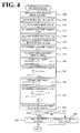
- FIG. 4 is a flowchart illustrating an example of a sleepiness assessment processing routine that is performed by the controller 30. This routine is repeatedly performed on a predetermined-time-by-predetermined-time basis.
- the CPU 32 of the controller 30 inputs data that is necessary for processing, such as the pulse wave signal that is output from the pulse wave sensor 22 and the respiration signal that is output from the respiration sensor 24 (step S100). Then, the CPU 32 extracts a peak (a maximal value) of the input pulse wave signal, and calculates, as a heartbeat interval RRI, the time difference between a currently extracted peak and the peak extracted immediately prior to the currently extracted peak (step S110).
- a waveform of the heartbeat interval RRI is illustrated in Fig. 5 .
- the CPU 32 calculates an average heart rate HR (times/min) for one minute (60000 msec) by using Equation (1), which is given below, on the basis of the calculated heartbeat interval RRI (step S120), and sets a sleepiness assessment value P1 to be the calculated average heart rate HR (step S130).
- the sleepiness assessment value P1 is one of parameters for determining whether or not the driver is sleepy, and is based on the fact that, in a situation in which a person cannot fall asleep, such as during driving, because the person is consciously trying to remain awake, the heart rate shows a tendency to temporarily increase.
- the CPU 32 sets the sleepiness assessment value P1
- the CPU 32 extracts a peak (a maximal value) of the input respiration signal, and calculates, as a respiration interval RespI, the time difference between a currently extracted peak and the peak extracted immediately prior to the currently extracted peak (step S140).
- a respiration interval RespI An example of a waveform of the respiration interval RespI is illustrated in Fig. 6 .
- the CPU 32 computes a standard deviation ⁇ of the calculated respiration interval RespI for one minute (step S150).
- the CPU 32 sets a sleepiness assessment value P2 to be the computed standard deviation ⁇ of the respiration interval RespI (step S160).
- the sleepiness assessment value P2 is one of the parameters for determining whether or not the driver is sleepy, and is based on the fact that, when a person feels sleepy, because the person yawns or breathes deeply more often, a large variation occurs in the respiration interval RespI, compared with that in a case where the person is sufficiently awake.
- the CPU 32 calculates an average heartbeat interval RRIavg from the heartbeat interval RRI, which has been calculated in step S110, by using Equation (2) given below (step S170), and sets an RRI count value Xi by using Equation (3) given below (step S180).
- the CPU 32 sets a sleepiness assessment value P3 on the basis of the set RRI count value Xi and the average heartbeat interval RRIavg by using Equation (4) given below (step S190).
- "n" in Equation (2) denotes the number of heartbeats per minute.
- Equation (3) when, for one minute, a heartbeat interval RRI (i) that is currently calculated is smaller than a heartbeat interval RRI (i-1) that was calculated immediately prior to the heartbeat interval RRI (i), the RRI count value Xi is incremented by a value of one (see Fig. 5 ).
- the sleepiness assessment value P3 is based on the fact that many examples are confirmed, in which, when a person feels sleepy, because a variation in which the heartbeat interval decreases frequently occurs, the frequency of the variation shows a tendency to gradually increase.
- the CPU 32 sets the sleepiness assessment value P3 by using Equation (5) given below (step S200), and sets a sleepiness assessment value P4 on the basis of the set RespI count value Yi by using Equation (6) given below (step S210).
- Equation (5) when, for one minute, a respiration interval RespI (i) that is currently calculated is larger than a respiration interval RespI (i-1) that was calculated immediately prior to the respiration interval RespI (i), the RespI count value Yi is incremented by a value of one (see Fig. 6 ).
- the sleepiness assessment value P4 is a value obtained by averaging a variation ratio in a case where a variation in which the respiration interval RespI increases occurs, and shows a tendency to increase as the frequency of an action of causing longer breathing, such as a deep breath or a yawn, increases.
- the CPU 32 sets the individual sleepiness assessment values P1 to P4 in this manner, the CPU 32 sums values that are obtained by multiplying the individual sleepiness assessment values P1 to P4 by coefficients a to d, each of which is set in advance for a corresponding one of the sleepiness assessment values P1 to P4, thereby setting a sleepiness assessment value P (step S220).
- the CPU 32 compares the set sleepiness assessment value P and a value of zero with each other (step S230). When the sleepiness assessment value P is smaller than the value of zero, the CPU 32 determines that the driver is in a state in which the driver does not feel sleepy, i.e., a state in which the driver is highly alert (step S240).
- the CPU 32 determines that the driver is in a state in which the driver feels sleepy, i.e., a state in which the driver is less alert (step S250).
- the CPU 32 finishes the present routine.
- the coefficients a to d are weight coefficients that are set for the sleepiness assessment values P1 to P4, respectively. Specific values of the coefficients a to d may be determined on the basis of experiments or the like.
- the controller 30 controls the vibration applying actuators so as to apply vibration at predetermined time intervals (for example, one-second intervals), thereby applying a stimulus to improve the degree of arousal.
- the scheme for applying a stimulus to the driver is not limited to thereto. Various schemes including provision of a sound such as a buzzer, provision of light such as room light, and application of a pressure using an air bag or the like may be employed.
- the sleepiness assessment value P4 is set by averaging a variation ratio in a case where a variation in which the respiration interval RespI increases occurs, and whether or not the driver is sleepy is determined using the set sleepiness assessment value P4 as one of the parameters. Thus, whether or not the driver is sleepy can be accurately determined using the indicator indicating the respiratory interval. Additionally, the sleepiness assessment value P is set using the four sleepiness assessment values P1 to P4 and the weights a to d, each of which is set for a corresponding one of the sleepiness assessment values P1 to P4.
- the average heart rate HR is used as the sleepiness assessment value P1.
- the standard deviation ⁇ of the respiration interval RespI for one minute is used as the sleepiness assessment value P2.
- a value, per unit time, of the square of the average heartbeat interval RRIavg in a case where the RRI count value Xi is the value of one is used as the sleepiness assessment value P3.
- determination of whether or not the driver is in the state in which the driver is less alert or the state in which the driver is high alert is performed on the basis of the sleepiness assessment value P.
- determination performed in the sleepiness assessment apparatus 20 is not limited thereto.
- Determination of the level of arousal using multiple steps that are equal to or more than three steps may be performed, for example, as follows: two thresholds Pref1 and Pref2 are set; when the sleepiness assessment value P is equal to or larger than the threshold Pref1, it is determined that the level of arousal is a high level; when the sleepiness assessment value P is equal to or larger than the threshold Pref2 and smaller than the threshold Pref1, it is determined that the level of arousal is a median level; and when the sleepiness assessment value P is smaller than the threshold Pref2, it is determined that the level of arousal is a low level.
- whether or not the driver is sleepy is determined using the four sleepiness assessment values P1 to P4. However, some of the sleepiness assessment values may be omitted, if at least either the sleepiness assessment value P3 or P4 is included as an indicator regarding variation in the respiration interval RespI. Whether or not the driver is sleepy may be determined using five or more sleepiness assessment values.
- the heartbeat interval RRI is calculated using the pulse wave sensor 22 as a heartbeat sensor.
- the pulse wave sensor 22 is not limited thereto. Any heartbeat sensor may be used if the heartbeat sensor is a sensor that can detect something corresponding to the cardiac signal, for example, a sensor in which an electrode is attached to each of grip portions of the steering wheel 14 on the left and right sides, and which detects a potential difference in a case where both hands are in contact with the electrodes on the left and right sides.
- a strain gauge is used as the respiration sensor 24.
- the respiration sensor 24 is not limited thereto. Any respiration sensor may be used if the respiration sensor is a sensor that can detect breathing movement, for example, a sensor that detects, by using laser ranging, movement of the thoracicoabdominal part which is made along with respiration.
- the respiration sensor 24 and the controller 30 that performs, in step S140 of the sleepiness assessment processing routine, the process of calculating the respiration interval RespI on the basis of the respiration signal that is output from the respiration sensor 24 correspond to "a respiration-interval acquisition unit".
- the controller 30 that performs, in steps S130, S150, and S160 to S250, the process of setting the sleepiness assessment value P4 by averaging the variation ratio in the case where a variation in which the respiration interval RespI increases occurs, of setting the sleepiness assessment value P using the sleepiness assessment values P1 to P4, which include the set sleepiness assessment value P4, and the weight coefficients a to d, of determining, when the set sleepiness assessment value P is smaller than the value of zero, that the driver is highly alert, and of determining, when the sleepiness assessment value P is equal to or larger than the value of zero, that the driver is less alert corresponds to "a sleepiness assessment unit". Furthermore, the controller 30 that performs, in step S110, the process of calculating the heartbeat interval RRI on the basis of the pulse wave signal which is output from the pulse wave sensor 22 and the pulse wave sensor 22 corresponds to "a heartbeat-interval acquisition unit".
- the present invention may be utilized in industries for producing sleepiness assessment apparatuses, automobile industries, and so forth.
Abstract
Description
- The present invention relates to a sleepiness assessment apparatus for determining the degree of sleepiness of a subject.
- Hitherto, an apparatus that detects a sleepy state of a driver in a vehicle has been proposed as this type of sleepiness assessment apparatus (for example, see PTL 1). In this apparatus, by utilizing the fact that activities of the sympathetic nervous system increase in a case where a person is in a state in which the person struggles against sleepiness, a time series of a cardiac cycle is acquired from a cardiac signal detected by a heartbeat sensor. Additionally, the amplitude spectral power of a low-frequency component of heart rate fluctuation is acquired from the time series of the cardiac cycle. When the amplitude spectral power of the low-frequency component of the heart rate fluctuation is larger than a predetermined value, it is determined that the degree of arousal is reduced. Note that, when it is determined that the degree of arousal is reduced, a stimulus, for example, a sound such as a buzzer, light such as meter illumination, or vibration, is applied in order to increase the degree of arousal of the driver.
- PTL 1:
JP 2008-161664 A - As described above, detection of a sleepy state of a driver in a vehicle at an early stage to prevent the driver from falling asleep at the wheel is considered to be a very significant safety issue. However, because there are large differences among individuals in a case of estimating autonomic nervous activities using the above-mentioned heart rate fluctuation, there occur cases in which detection of a sleepy state cannot be stably performed.
- It is a main object of a sleepiness assessment apparatus according to the present invention to accurately determine the degree of sleepiness of a person.
- The sleepiness assessment apparatus according to the present invention employs the following means in order to achieve the above-mentioned main object.
- The sleepiness assessment apparatus according to the present invention is
a sleepiness assessment apparatus for determining whether or not a subject is sleepy, the sleepiness assessment apparatus comprising: - a respiration-interval acquisition unit for acquiring a respiration interval of the subject; and
- a sleepiness assessment unit for determining, in a case where a variation in which the acquired respiration interval increases occurs, by using a degree of the variation as a sleepiness assessment parameter, whether or not the subject is sleepy.
- In the sleepiness assessment apparatus according to the present invention, the respiration interval of the subject is acquired, and, in the case where a variation in which the acquired respiration interval increases occurs, whether or not the subject is sleepy is determined by using a degree of the variation as the sleepiness assessment parameter. The sleepiness assessment parameter is based on the fact that, when a person feels sleepy, because the person yawns or breathes deeply more often, the respiration interval varies by a large amount, compared with that in a case where the person is sufficiently awake. Accordingly, whether or not the subject is sleepy can more accurately be determined.
- In the above-described sleepiness assessment apparatus according to the present invention, the sleepiness assessment parameter may be a parameter that is, in the case where a variation in which the acquired respiration interval increases occurs, obtained on the basis of a ratio obtained by the variation. In this manner, whether or not the subject is sleepy can be further accurately determined.
- Additionally, in the sleepiness assessment apparatus according to the present invention, the sleepiness assessment parameter may be a parameter that is obtained by calculating a standard deviation of the acquired respiration interval. In this manner, whether or not the subject is sleepy can be further accurately determined.
- Moreover, in the sleepiness assessment apparatus according to the present invention, the sleepiness assessment parameter may include a plurality of sleepiness assessment parameters, and the sleepiness assessment unit may determine, by using the plurality of sleepiness assessment parameters and weights, each of the weights being set for a corresponding one of the plurality of sleepiness assessment parameters, whether or not the subject is sleepy. In this manner, even when it is supposed that a reaction of a person in a case where the person feels sleepy varies with individuals, whether or not the subject is sleepy can be more accurately determined.
- Additionally, the sleepiness assessment apparatus according to the present invention may further include a heartbeat-interval acquisition unit for acquiring a heartbeat interval of the subject. The sleepiness assessment unit may calculate an average value of the acquired heartbeat interval, and determine, in a case where a variation in which the acquired heartbeat interval decreases occurs, by using a frequency of the variation and the calculated average value of the heartbeat interval as the sleepiness assessment parameter, whether or not the subject is sleepy. In the sleepiness assessment apparatus according to this aspect of the present invention, the sleepiness assessment parameter may be a parameter that is, every time a variation in which the acquired heartbeat interval decreases occurs, obtained by multiplying the calculated average value of the heartbeat interval by a value which is obtained by dividing the acquired heartbeat interval by the number of heartbeats per unit time. In this case, the sleepiness assessment parameter may be a parameter that is, every time a variation in which the acquired heartbeat interval decreases occurs, obtained by integrating a square of the calculated average value of the heartbeat interval to obtain an integrated value, and by dividing the integrated value by a unit time.
-
-
Fig. 1 is a configuration diagram schematically illustrating a configuration of an anti-dozing system including asleepiness assessment apparatus 20 that is provided as an embodiment of the present invention. -
Fig. 2 is an explanatory diagram for explaining a heartbeat interval RRI of an electrocardiogram. -
Fig. 3 is an explanatory diagram illustrating an example of a waveform of a signal detected by arespiration sensor 24. -
Fig. 4 is a flowchart illustrating an example of a sleepiness assessment processing routine that is performed by acontroller 30. -
Fig. 5 is an explanatory diagram illustrating an example of a waveform of the heartbeat interval RRI. -
Fig. 6 is an explanatory diagram illustrating an example of a waveform of a respiration interval Respl. - Next, preferred embodiments of the present invention will be described.
Fig. 1 is a configuration diagram schematically illustrating a configuration of an anti-dozing system including asleepiness assessment apparatus 20 that is provided as an embodiment of the present invention. Thesleepiness assessment apparatus 20 according to the embodiment is configured as an apparatus that is mounted in an automobile and that is used to determine the degree of sleepiness of a driver. As illustrated in the figure, thesleepiness assessment apparatus 20 includes apulse wave sensor 22 that detects a pulse wave of the driver, arespiration sensor 24 that detects breathing movement of the driver, and acontroller 30 that performs overall control of the apparatus. - The
pulse wave sensor 22 is attached to a grip portion of asteering wheel 14. Thepulse wave sensor 22 is an optical sensor that is constituted by a light emitting element which emits near infrared light so that the driver is irradiated with the near infrared light from the skin surface and a light receiving element which receives transmitted light or reflected light. Thepulse wave sensor 22 detects, as change in the amount of light, change in the volume flow of blood flowing through peripheral blood vessels. It is considered that a peak-to-peak interval of an acceleration pulse wave which is obtained by a signal detected by thepulse wave sensor 22 corresponds to an interval (heartbeat interval) between R waves of an electrocardiogram illustrated inFig. 2 . The signal detected by thepulse wave sensor 22 is output, in a wireless or wired manner, to thecontroller 30 via an amplifier and a filter for reducing noise. - The
respiration sensor 24 is a strain gauge that is attached to an area which comes into contact with the thoracicoabdominal part of the driver when aseat belt 12 is fastened. Therespiration sensor 24 detects, as change in an electric resistance, movement of the chest or the abdomen of the driver when the driver breathes. InFig. 3 , an example of a waveform of a signal detected by therespiration sensor 24 is illustrated. The signal detected by therespiration sensor 24 is output, in a wireless or wired manner, to thecontroller 30 via an amplifier and a filter for reducing noise. - The
controller 30 is configured as a microprocessor in which aCPU 32 serves as a central unit. In addition to theCPU 32, thecontroller 30 includes aROM 34 in which a processing program is stored, aRAM 36 that temporarily stores data, and an input/output port that is not illustrated. The pulse wave signal that is output from thepulse wave sensor 22, the respiration signal that is output from therespiration sensor 24, and so forth are input to thecontroller 30 via the input port. Furthermore, drive signals that are to be provided to vibration applying actuators (motors) 42, 44, and 46, which are embedded in a backrest portion of aseat 10, afootrest 16, and thesteering wheel 14 and which apply vibration, and so forth are output from thecontroller 30 via the output port. - Next, an operation of the
sleepiness assessment apparatus 20 having the above-described configuration will be described.Fig. 4 is a flowchart illustrating an example of a sleepiness assessment processing routine that is performed by thecontroller 30. This routine is repeatedly performed on a predetermined-time-by-predetermined-time basis. - When the sleepiness assessment processing routine is performed, first, the
CPU 32 of thecontroller 30 inputs data that is necessary for processing, such as the pulse wave signal that is output from thepulse wave sensor 22 and the respiration signal that is output from the respiration sensor 24 (step S100). Then, theCPU 32 extracts a peak (a maximal value) of the input pulse wave signal, and calculates, as a heartbeat interval RRI, the time difference between a currently extracted peak and the peak extracted immediately prior to the currently extracted peak (step S110). An example of a waveform of the heartbeat interval RRI is illustrated inFig. 5 . Then, theCPU 32 calculates an average heart rate HR (times/min) for one minute (60000 msec) by using Equation (1), which is given below, on the basis of the calculated heartbeat interval RRI (step S120), and sets a sleepiness assessment value P1 to be the calculated average heart rate HR (step S130). Here, the sleepiness assessment value P1 is one of parameters for determining whether or not the driver is sleepy, and is based on the fact that, in a situation in which a person cannot fall asleep, such as during driving, because the person is consciously trying to remain awake, the heart rate shows a tendency to temporarily increase. -

- When the
CPU 32 sets the sleepiness assessment value P1, next, theCPU 32 extracts a peak (a maximal value) of the input respiration signal, and calculates, as a respiration interval RespI, the time difference between a currently extracted peak and the peak extracted immediately prior to the currently extracted peak (step S140). An example of a waveform of the respiration interval RespI is illustrated inFig. 6 . Then, theCPU 32 computes a standard deviation σ of the calculated respiration interval RespI for one minute (step S150). TheCPU 32 sets a sleepiness assessment value P2 to be the computed standard deviation σ of the respiration interval RespI (step S160). Here, the sleepiness assessment value P2 is one of the parameters for determining whether or not the driver is sleepy, and is based on the fact that, when a person feels sleepy, because the person yawns or breathes deeply more often, a large variation occurs in the respiration interval RespI, compared with that in a case where the person is sufficiently awake. - When the
CPU 32 sets the sleepiness assessment value P2, theCPU 32 calculates an average heartbeat interval RRIavg from the heartbeat interval RRI, which has been calculated in step S110, by using Equation (2) given below (step S170), and sets an RRI count value Xi by using Equation (3) given below (step S180). TheCPU 32 sets a sleepiness assessment value P3 on the basis of the set RRI count value Xi and the average heartbeat interval RRIavg by using Equation (4) given below (step S190). Here, "n" in Equation (2) denotes the number of heartbeats per minute. Furthermore, as represented by Equation (3), when, for one minute, a heartbeat interval RRI (i) that is currently calculated is smaller than a heartbeat interval RRI (i-1) that was calculated immediately prior to the heartbeat interval RRI (i), the RRI count value Xi is incremented by a value of one (seeFig. 5 ).
The sleepiness assessment value P3 is based on the fact that many examples are confirmed, in which, when a person feels sleepy, because a variation in which the heartbeat interval decreases frequently occurs, the frequency of the variation shows a tendency to gradually increase. -


- When the
CPU 32 sets the sleepiness assessment value P3, theCPU 32 sets a RespI count value Yi by using Equation (5) given below (step S200), and sets a sleepiness assessment value P4 on the basis of the set RespI count value Yi by using Equation (6) given below (step S210). Here, as represented by Equation (5), when, for one minute, a respiration interval RespI (i) that is currently calculated is larger than a respiration interval RespI (i-1) that was calculated immediately prior to the respiration interval RespI (i), the RespI count value Yi is incremented by a value of one (seeFig. 6 ). As is clear from Equation (6), the sleepiness assessment value P4 is a value obtained by averaging a variation ratio in a case where a variation in which the respiration interval RespI increases occurs, and shows a tendency to increase as the frequency of an action of causing longer breathing, such as a deep breath or a yawn, increases. -


- When the
CPU 32 sets the individual sleepiness assessment values P1 to P4 in this manner, theCPU 32 sums values that are obtained by multiplying the individual sleepiness assessment values P1 to P4 by coefficients a to d, each of which is set in advance for a corresponding one of the sleepiness assessment values P1 to P4, thereby setting a sleepiness assessment value P (step S220). TheCPU 32 compares the set sleepiness assessment value P and a value of zero with each other (step S230). When the sleepiness assessment value P is smaller than the value of zero, theCPU 32 determines that the driver is in a state in which the driver does not feel sleepy, i.e., a state in which the driver is highly alert (step S240). When the set sleepiness assessment value P is equal to or larger than the value of zero, theCPU 32 determines that the driver is in a state in which the driver feels sleepy, i.e., a state in which the driver is less alert (step S250). TheCPU 32 finishes the present routine. Here, the coefficients a to d are weight coefficients that are set for the sleepiness assessment values P1 to P4, respectively. Specific values of the coefficients a to d may be determined on the basis of experiments or the like. The reason why the sleepiness assessment value P for determining whether or not the driver feels sleepy is set using the multiple sleepiness assessment values P1 to P4 and the coefficients a to d as described above is that, because indicators indicating a reaction of a person in a case where the person feels sleepy vary with individuals, stable determination cannot be performed using single physiological indicator in most cases. Note that, in the embodiment, when it is determined in the sleepiness assessment processing routine that the driver is less alert, thecontroller 30 controls the vibration applying actuators so as to apply vibration at predetermined time intervals (for example, one-second intervals), thereby applying a stimulus to improve the degree of arousal. As a matter of course, the scheme for applying a stimulus to the driver is not limited to thereto. Various schemes including provision of a sound such as a buzzer, provision of light such as room light, and application of a pressure using an air bag or the like may be employed. - In the
sleepiness assessment apparatus 20 according to the embodiment described above, the sleepiness assessment value P4 is set by averaging a variation ratio in a case where a variation in which the respiration interval RespI increases occurs, and whether or not the driver is sleepy is determined using the set sleepiness assessment value P4 as one of the parameters. Thus, whether or not the driver is sleepy can be accurately determined using the indicator indicating the respiratory interval. Additionally, the sleepiness assessment value P is set using the four sleepiness assessment values P1 to P4 and the weights a to d, each of which is set for a corresponding one of the sleepiness assessment values P1 to P4. Thus, even when it is supposed that that indicators indicating a reaction of a person in a case where the person feels sleepy vary with individuals, more stable determination of whether or not the driver is sleepy can be performed. Furthermore, the average heart rate HR is used as the sleepiness assessment value P1. The standard deviation σ of the respiration interval RespI for one minute is used as the sleepiness assessment value P2. A value, per unit time, of the square of the average heartbeat interval RRIavg in a case where the RRI count value Xi is the value of one is used as the sleepiness assessment value P3. Thus, whether or not the driver is sleepy can be more accurately determined. - In the
sleepiness assessment apparatus 20 according to the embodiment, determination of whether or not the driver is in the state in which the driver is less alert or the state in which the driver is high alert, i.e., determination using two steps, is performed on the basis of the sleepiness assessment value P. However, determination performed in thesleepiness assessment apparatus 20 is not limited thereto. Determination of the level of arousal using multiple steps that are equal to or more than three steps may be performed, for example, as follows: two thresholds Pref1 and Pref2 are set; when the sleepiness assessment value P is equal to or larger than the threshold Pref1, it is determined that the level of arousal is a high level; when the sleepiness assessment value P is equal to or larger than the threshold Pref2 and smaller than the threshold Pref1, it is determined that the level of arousal is a median level; and when the sleepiness assessment value P is smaller than the threshold Pref2, it is determined that the level of arousal is a low level. - In the
sleepiness assessment apparatus 20 according to the embodiment, whether or not the driver is sleepy is determined using the four sleepiness assessment values P1 to P4. However, some of the sleepiness assessment values may be omitted, if at least either the sleepiness assessment value P3 or P4 is included as an indicator regarding variation in the respiration interval RespI. Whether or not the driver is sleepy may be determined using five or more sleepiness assessment values. - In the
sleepiness assessment apparatus 20 according to the embodiment, the heartbeat interval RRI is calculated using thepulse wave sensor 22 as a heartbeat sensor. However, thepulse wave sensor 22 is not limited thereto. Any heartbeat sensor may be used if the heartbeat sensor is a sensor that can detect something corresponding to the cardiac signal, for example, a sensor in which an electrode is attached to each of grip portions of thesteering wheel 14 on the left and right sides, and which detects a potential difference in a case where both hands are in contact with the electrodes on the left and right sides. - In the
sleepiness assessment apparatus 20 according to the embodiment, a strain gauge is used as therespiration sensor 24. However, therespiration sensor 24 is not limited thereto. Any respiration sensor may be used if the respiration sensor is a sensor that can detect breathing movement, for example, a sensor that detects, by using laser ranging, movement of the thoracicoabdominal part which is made along with respiration. - The relationships between main elements in the embodiment and main elements, which are described in Means for Solving the Problems, of the invention will be described. In the embodiment, the
respiration sensor 24 and thecontroller 30 that performs, in step S140 of the sleepiness assessment processing routine, the process of calculating the respiration interval RespI on the basis of the respiration signal that is output from therespiration sensor 24 correspond to "a respiration-interval acquisition unit". Thecontroller 30 that performs, in steps S130, S150, and S160 to S250, the process of setting the sleepiness assessment value P4 by averaging the variation ratio in the case where a variation in which the respiration interval RespI increases occurs, of setting the sleepiness assessment value P using the sleepiness assessment values P1 to P4, which include the set sleepiness assessment value P4, and the weight coefficients a to d, of determining, when the set sleepiness assessment value P is smaller than the value of zero, that the driver is highly alert, and of determining, when the sleepiness assessment value P is equal to or larger than the value of zero, that the driver is less alert corresponds to "a sleepiness assessment unit". Furthermore, thecontroller 30 that performs, in step S110, the process of calculating the heartbeat interval RRI on the basis of the pulse wave signal which is output from thepulse wave sensor 22 and thepulse wave sensor 22 corresponds to "a heartbeat-interval acquisition unit". - The embodiments of the present invention are described above. However, the present invention is not limited to the above-described embodiments at all. As a matter of course, various modifications may be made without departing from the gist of the present invention.
- The present application claims priority on the basis of Japanese Patent Application No.
2009-137551 filed on June 8, 2009 - The present invention may be utilized in industries for producing sleepiness assessment apparatuses, automobile industries, and so forth.
Claims (7)
- A sleepiness assessment apparatus for determining whether or not a subject is sleepy, the sleepiness assessment apparatus comprising:a respiration-interval acquisition unit for acquiring a respiration interval of the subject; anda sleepiness assessment unit for determining, in a case where a variation in which the acquired respiration interval increases occurs, by using a degree of the variation as a sleepiness assessment parameter, whether or not the subject is sleepy.
- The sleepiness assessment apparatus according to Claim 1,
wherein the sleepiness assessment parameter is a parameter that is, in the case where a variation in which the acquired respiration interval increases occurs, obtained on the basis of a ratio obtained by the variation. - The sleepiness assessment apparatus according to Claim 1 or 2,
wherein the sleepiness assessment parameter is a parameter that is obtained on the basis of a standard deviation of the acquired respiration interval. - The sleepiness assessment apparatus according to any one of Claims 1 to 3,
wherein the sleepiness assessment parameter includes a plurality of sleepiness assessment parameters, and the sleepiness assessment unit determines, by using the plurality of sleepiness assessment parameters and weights, whether or not the subject is sleepy, each of the weights being set for a corresponding one of the plurality of sleepiness assessment parameters. - The sleepiness assessment apparatus according to any one of Claims 1 to 4, further comprising
a heartbeat-interval acquisition unit for acquiring a heartbeat interval of the subject,
wherein the sleepiness assessment unit calculates an average value of the acquired heartbeat interval, and determines, in a case where a variation in which the acquired heartbeat interval decreases occurs, by using a frequency of the variation and the calculated average value of the heartbeat interval as the sleepiness assessment parameter, whether or not the subject is sleepy. - The sleepiness assessment apparatus according to Claim 5,
wherein the sleepiness assessment parameter is a parameter that is, every time a variation in which the acquired heartbeat interval decreases occurs, obtained by multiplying the calculated average value of the heartbeat interval by a value which is obtained by dividing the acquired heartbeat interval by the number of heartbeats per unit time. - The sleepiness assessment apparatus according to Claim 6,
wherein the sleepiness assessment parameter is a parameter that is, every time a variation in which the acquired heartbeat interval decreases occurs, obtained by integrating a square of the calculated average value of the heartbeat interval to obtain an integrated value, and by dividing the integrated value by a unit time.
Applications Claiming Priority (2)
| Application Number | Priority Date | Filing Date | Title |
|---|---|---|---|
| JP2009137551 | 2009-06-08 | ||
| PCT/JP2010/058904 WO2010143535A1 (en) | 2009-06-08 | 2010-05-26 | Sleepiness assessment device |
Publications (2)
| Publication Number | Publication Date |
|---|---|
| EP2441387A1 true EP2441387A1 (en) | 2012-04-18 |
| EP2441387A4 EP2441387A4 (en) | 2014-12-31 |
Family
ID=43308790
Family Applications (1)
| Application Number | Title | Priority Date | Filing Date |
|---|---|---|---|
| EP10786066.0A Ceased EP2441387A4 (en) | 2009-06-08 | 2010-05-26 | Sleepiness assessment device |
Country Status (4)
| Country | Link |
|---|---|
| US (1) | US8979761B2 (en) |
| EP (1) | EP2441387A4 (en) |
| JP (1) | JP5704612B2 (en) |
| WO (1) | WO2010143535A1 (en) |
Cited By (1)
| Publication number | Priority date | Publication date | Assignee | Title |
|---|---|---|---|---|
| JP2015080520A (en) * | 2013-10-21 | 2015-04-27 | テイ・エス テック株式会社 | Awakening device, sheet and method of judging a degree of awakening |
Families Citing this family (21)
| Publication number | Priority date | Publication date | Assignee | Title |
|---|---|---|---|---|
| JP2013027514A (en) * | 2011-07-28 | 2013-02-07 | Nissan Motor Co Ltd | Driver condition determining apparatus, and driver condition determination method |
| JP5744780B2 (en) * | 2012-03-21 | 2015-07-08 | 株式会社デンソー | Random state judgment device |
| US10758168B2 (en) * | 2012-06-18 | 2020-09-01 | The Boeing Company | Method and system for the automated assessment of fatigue mitigation strategies |
| JP6063775B2 (en) * | 2013-03-01 | 2017-01-18 | 東洋紡株式会社 | Dozing prevention method and dozing prevention device |
| JP6124011B2 (en) * | 2013-10-21 | 2017-05-10 | テイ・エス テック株式会社 | Awakening device and seat |
| CN104442989A (en) * | 2014-11-24 | 2015-03-25 | 京东方科技集团股份有限公司 | Automobile steering wheel |
| JP6596847B2 (en) * | 2015-03-09 | 2019-10-30 | 富士通株式会社 | Awakening degree determination program and awakening degree determination device |
| JP6544797B2 (en) * | 2015-04-15 | 2019-07-17 | 本田技研工業株式会社 | Fatigue detection device |
| FI126600B (en) * | 2015-08-10 | 2017-03-15 | Murata Manufacturing Co | Detection of sleep phenomenon using ballistocardiography |
| JP6114802B1 (en) * | 2015-10-30 | 2017-04-12 | テイ・エス テック株式会社 | Awakening state judgment method |
| US9955925B2 (en) * | 2015-12-18 | 2018-05-01 | Microsoft Technology Licensing, Llc | Drowsiness onset detection |
| JP6512114B2 (en) * | 2016-01-13 | 2019-05-15 | 株式会社デンソー | Breath detection device |
| JP6603584B2 (en) * | 2016-01-14 | 2019-11-06 | 株式会社クロスウェル | Periodic wave detection device, periodic wave detection method and program |
| US20190117144A1 (en) * | 2016-04-08 | 2019-04-25 | Magna Seating Inc. | Heart rate variability and drowsiness detection |
| JP6707969B2 (en) * | 2016-04-19 | 2020-06-10 | トヨタ自動車株式会社 | Arousal level determination device |
| JP6836358B2 (en) * | 2016-08-29 | 2021-03-03 | パイオニア株式会社 | Drowsiness estimation device |
| JP6968526B2 (en) * | 2016-10-19 | 2021-11-17 | テイ・エス テック株式会社 | Wakefulness determination device, Wakefulness determination method and program |
| JP6892586B2 (en) * | 2016-11-17 | 2021-06-23 | テイ・エス テック株式会社 | Vehicle seat |
| DE102017201405B4 (en) | 2017-01-30 | 2018-12-13 | Audi Ag | Method for operating a motor vehicle |
| CN107582081B (en) * | 2017-10-31 | 2020-01-10 | 京东方科技集团股份有限公司 | Detection device and fatigue detection system |
| KR102154999B1 (en) * | 2019-04-05 | 2020-09-11 | 경북대학교 산학협력단 | System for detecting drowsiness of driver and method thereof |
Citations (6)
| Publication number | Priority date | Publication date | Assignee | Title |
|---|---|---|---|---|
| JPH08182667A (en) | 1994-12-28 | 1996-07-16 | Toyota Motor Corp | Awakening-degree judgement device |
| JPH11314534A (en) | 1998-05-06 | 1999-11-16 | Nissan Motor Co Ltd | Caution ability reduction preventive device for vehicle |
| JP2005342188A (en) | 2004-06-02 | 2005-12-15 | Delta Tooling Co Ltd | System for deciding mental and physical condition |
| US20060155175A1 (en) | 2003-09-02 | 2006-07-13 | Matsushita Electric Industrial Co., Ltd. | Biological sensor and support system using the same |
| JP2006182667A (en) | 2004-12-27 | 2006-07-13 | Lion Corp | Water-containing oral cavity gel composition |
| US20100049066A1 (en) | 2006-12-04 | 2010-02-25 | Toyota Jidosha Kabushiki Kaisha | Device for judging degree of awakening and method for judging degree of awakening |
Family Cites Families (23)
| Publication number | Priority date | Publication date | Assignee | Title |
|---|---|---|---|---|
| JP2671394B2 (en) * | 1988-06-23 | 1997-10-29 | 日産自動車株式会社 | Driver abnormal condition detection device |
| JP2760019B2 (en) * | 1989-03-17 | 1998-05-28 | オムロン株式会社 | Snooze detection device |
| JPH04183439A (en) | 1990-11-17 | 1992-06-30 | Colleen Denshi Kk | Device for detecting dozing of driver |
| US5769085A (en) * | 1993-01-06 | 1998-06-23 | Mitsubishi Jidosha Kogyo Kabushiki Kaisha | Apparatus for detecting awareness of a vehicle driver and method thereof |
| JPH0759757A (en) * | 1993-08-25 | 1995-03-07 | Tsutomu Suzuki | Physical condition detector |
| SE508285C2 (en) | 1994-06-07 | 1998-09-21 | Biosys Ab | Method and apparatus for assessing wakefulness and drowsiness at various stages between wakefulness and sleep in a way that is not monitored non-interfering |
| AU746688B2 (en) * | 1998-09-02 | 2002-05-02 | Med-Dev Limited | Method and apparatus for subject monitoring |
| WO2000044580A1 (en) * | 1999-01-27 | 2000-08-03 | Compumedics Sleep Pty. Ltd. | Vigilance monitoring system |
| SE517648C2 (en) * | 1999-09-14 | 2002-07-02 | Biosys Ab | Procedure and system for monitoring a vehicle driver |
| JP4514372B2 (en) * | 2001-08-28 | 2010-07-28 | パイオニア株式会社 | Information providing system, information providing method, information providing program, server device in information providing system, and terminal device in information providing system |
| JP2004290324A (en) | 2003-03-26 | 2004-10-21 | Honda Motor Co Ltd | Apparatus for judging vigilance of crew |
| US7319899B2 (en) | 2003-04-23 | 2008-01-15 | Medtronic, Inc. | Sensing techniques for implantable medical devices |
| JP3966833B2 (en) * | 2003-05-12 | 2007-08-29 | パイオニア株式会社 | Biological information detection device |
| JP4331977B2 (en) * | 2003-05-21 | 2009-09-16 | パイオニア株式会社 | Mental state determination device and mental state determination method |
| JP4111062B2 (en) * | 2003-05-27 | 2008-07-02 | 株式会社デンソー | Sleepiness level detection device |
| JP2005095408A (en) * | 2003-09-25 | 2005-04-14 | Matsushita Electric Ind Co Ltd | Biological condition judgement apparatus and supporting system |
| US8725244B2 (en) | 2004-03-16 | 2014-05-13 | Medtronic, Inc. | Determination of sleep quality for neurological disorders |
| JP4081686B2 (en) | 2004-07-05 | 2008-04-30 | ソニー株式会社 | Biological information processing apparatus and video / audio reproduction apparatus |
| US20080071177A1 (en) * | 2005-04-28 | 2008-03-20 | Pioneer Corporation | Bioinformation Sensor |
| JP2007000280A (en) * | 2005-06-22 | 2007-01-11 | Toyota Motor Corp | Arousal lowering determination device |
| JP4739407B2 (en) * | 2006-03-24 | 2011-08-03 | パイオニア株式会社 | Driver's mental state detection device |
| JP2008154681A (en) * | 2006-12-21 | 2008-07-10 | Toyota Motor Corp | Sleep stage determination apparatus and method |
| JP4900223B2 (en) | 2007-12-11 | 2012-03-21 | 株式会社ダイフク | Car wash machine |
-
2010
- 2010-05-26 JP JP2011518410A patent/JP5704612B2/en not_active Expired - Fee Related
- 2010-05-26 WO PCT/JP2010/058904 patent/WO2010143535A1/en active Application Filing
- 2010-05-26 US US13/376,719 patent/US8979761B2/en not_active Expired - Fee Related
- 2010-05-26 EP EP10786066.0A patent/EP2441387A4/en not_active Ceased
Patent Citations (6)
| Publication number | Priority date | Publication date | Assignee | Title |
|---|---|---|---|---|
| JPH08182667A (en) | 1994-12-28 | 1996-07-16 | Toyota Motor Corp | Awakening-degree judgement device |
| JPH11314534A (en) | 1998-05-06 | 1999-11-16 | Nissan Motor Co Ltd | Caution ability reduction preventive device for vehicle |
| US20060155175A1 (en) | 2003-09-02 | 2006-07-13 | Matsushita Electric Industrial Co., Ltd. | Biological sensor and support system using the same |
| JP2005342188A (en) | 2004-06-02 | 2005-12-15 | Delta Tooling Co Ltd | System for deciding mental and physical condition |
| JP2006182667A (en) | 2004-12-27 | 2006-07-13 | Lion Corp | Water-containing oral cavity gel composition |
| US20100049066A1 (en) | 2006-12-04 | 2010-02-25 | Toyota Jidosha Kabushiki Kaisha | Device for judging degree of awakening and method for judging degree of awakening |
Non-Patent Citations (1)
| Title |
|---|
| See also references of WO2010143535A1 |
Cited By (3)
| Publication number | Priority date | Publication date | Assignee | Title |
|---|---|---|---|---|
| JP2015080520A (en) * | 2013-10-21 | 2015-04-27 | テイ・エス テック株式会社 | Awakening device, sheet and method of judging a degree of awakening |
| EP3061396A4 (en) * | 2013-10-21 | 2016-11-09 | Ts Tech Co Ltd | Alertness device, seat, and method for determining alertness |
| US9693726B2 (en) | 2013-10-21 | 2017-07-04 | Ts Tech Co., Ltd. | Alertness device, seat, and method for determining alertness |
Also Published As
| Publication number | Publication date |
|---|---|
| EP2441387A4 (en) | 2014-12-31 |
| US20120078122A1 (en) | 2012-03-29 |
| JPWO2010143535A1 (en) | 2012-11-22 |
| WO2010143535A1 (en) | 2010-12-16 |
| US8979761B2 (en) | 2015-03-17 |
| JP5704612B2 (en) | 2015-04-22 |
Similar Documents
| Publication | Publication Date | Title |
|---|---|---|
| US8979761B2 (en) | Sleepiness assessment apparatus | |
| JP4247055B2 (en) | Driver's seat system | |
| KR100563641B1 (en) | Sleepiness level detection device | |
| US7397382B2 (en) | Drowsiness detecting apparatus and method | |
| JP6124011B2 (en) | Awakening device and seat | |
| JP6579890B2 (en) | Fatigue meter | |
| US7250029B2 (en) | Human condition evaluation system, computer program, and computer-readable record medium | |
| JP2010142456A (en) | Heartbeat detecting apparatus | |
| JP2014100227A (en) | Concentration degree estimation apparatus, concentration degree estimation method, driving assistance apparatus, and driving assistance method | |
| EP2638855A1 (en) | Sleep state estimation device | |
| JP2017063966A (en) | Fatigue degree meter | |
| JP3596198B2 (en) | Driver monitoring device | |
| JP2008264138A (en) | Sleep state judgement apparatus, sleep state judgement method and computer program | |
| EP2438862B1 (en) | Wakefulness level determination device, wakefulness level determination method, and wakefulness level determination program | |
| JP2020074805A (en) | Method and device for presuming driver's state | |
| EP2962638B1 (en) | Dozing prevention method | |
| JP4452145B2 (en) | Heart rate detector | |
| JP2010162069A (en) | Apparatus, method and program for estimating age by non-contact biological information collection | |
| JP2013252764A (en) | Doze warning device | |
| JP2014012042A (en) | Drowsiness determination method, device, and program | |
| KR20070028745A (en) | Nonconscious measurement method and device for the driver's heart beating signal and respiration signal | |
| JP2013255734A (en) | Doze warning device | |
| US20180055436A1 (en) | Fatigue detection apparatus and fatigue detection method | |
| Lee et al. | Development of a Real-Time Driver Health Detection System Using a Smart Steering Wheel | |
| KR20180101784A (en) | arrhythmia diagnostic method and apparatus using signal of electrocardiogram for driver |
Legal Events
| Date | Code | Title | Description |
|---|---|---|---|
| PUAI | Public reference made under article 153(3) epc to a published international application that has entered the european phase |
Free format text: ORIGINAL CODE: 0009012 |
|
| 17P | Request for examination filed |
Effective date: 20111208 |
|
| AK | Designated contracting states |
Kind code of ref document: A1 Designated state(s): AL AT BE BG CH CY CZ DE DK EE ES FI FR GB GR HR HU IE IS IT LI LT LU LV MC MK MT NL NO PL PT RO SE SI SK SM TR |
|
| DAX | Request for extension of the european patent (deleted) | ||
| A4 | Supplementary search report drawn up and despatched |
Effective date: 20141127 |
|
| RIC1 | Information provided on ipc code assigned before grant |
Ipc: A61B 5/18 20060101ALI20141121BHEP Ipc: A61B 5/11 20060101ALI20141121BHEP Ipc: A61B 5/16 20060101AFI20141121BHEP Ipc: A61B 5/0245 20060101ALI20141121BHEP |
|
| TPAC | Observations filed by third parties |
Free format text: ORIGINAL CODE: EPIDOSNTIPA |
|
| 17Q | First examination report despatched |
Effective date: 20160414 |
|
| REG | Reference to a national code |
Ref country code: DE Ref legal event code: R003 |
|
| STAA | Information on the status of an ep patent application or granted ep patent |
Free format text: STATUS: THE APPLICATION HAS BEEN REFUSED |
|
| 18R | Application refused |
Effective date: 20180708 |