EP2441682A1 - Device for channelled distribution of tablets and method for implementing same - Google Patents
Device for channelled distribution of tablets and method for implementing same Download PDFInfo
- Publication number
- EP2441682A1 EP2441682A1 EP10013547A EP10013547A EP2441682A1 EP 2441682 A1 EP2441682 A1 EP 2441682A1 EP 10013547 A EP10013547 A EP 10013547A EP 10013547 A EP10013547 A EP 10013547A EP 2441682 A1 EP2441682 A1 EP 2441682A1
- Authority
- EP
- European Patent Office
- Prior art keywords
- upstream
- ramp
- channels
- downstream
- tablets
- Prior art date
- Legal status (The legal status is an assumption and is not a legal conclusion. Google has not performed a legal analysis and makes no representation as to the accuracy of the status listed.)
- Granted
Links
- 238000000034 method Methods 0.000 title claims abstract description 8
- 238000009826 distribution Methods 0.000 title claims description 10
- 238000011144 upstream manufacturing Methods 0.000 claims abstract description 118
- 238000006073 displacement reaction Methods 0.000 claims abstract description 13
- 239000003826 tablet Substances 0.000 claims abstract description 13
- 238000004806 packaging method and process Methods 0.000 claims abstract description 11
- 238000004891 communication Methods 0.000 claims abstract description 6
- 239000007891 compressed tablet Substances 0.000 claims abstract 3
- 238000001514 detection method Methods 0.000 claims description 6
- 230000001413 cellular effect Effects 0.000 claims description 5
- 230000001960 triggered effect Effects 0.000 claims description 4
- 230000005693 optoelectronics Effects 0.000 claims description 3
- 230000000737 periodic effect Effects 0.000 claims description 3
- 238000000151 deposition Methods 0.000 claims 1
- 238000012856 packing Methods 0.000 claims 1
- 230000003252 repetitive effect Effects 0.000 claims 1
- 238000009825 accumulation Methods 0.000 description 4
- 239000002775 capsule Substances 0.000 description 4
- 230000005465 channeling Effects 0.000 description 4
- 230000003750 conditioning effect Effects 0.000 description 4
- 235000021183 entrée Nutrition 0.000 description 4
- 230000005484 gravity Effects 0.000 description 3
- 229910052751 metal Inorganic materials 0.000 description 3
- 239000002184 metal Substances 0.000 description 3
- 230000001681 protective effect Effects 0.000 description 3
- 230000000903 blocking effect Effects 0.000 description 2
- 235000013305 food Nutrition 0.000 description 2
- 229910052782 aluminium Inorganic materials 0.000 description 1
- XAGFODPZIPBFFR-UHFFFAOYSA-N aluminium Chemical compound [Al] XAGFODPZIPBFFR-UHFFFAOYSA-N 0.000 description 1
- 230000005540 biological transmission Effects 0.000 description 1
- 238000004140 cleaning Methods 0.000 description 1
- 238000010276 construction Methods 0.000 description 1
- 238000005520 cutting process Methods 0.000 description 1
- 238000010586 diagram Methods 0.000 description 1
- 239000000428 dust Substances 0.000 description 1
- 238000009434 installation Methods 0.000 description 1
- 230000001788 irregular Effects 0.000 description 1
- 238000004519 manufacturing process Methods 0.000 description 1
- 239000000463 material Substances 0.000 description 1
- 230000003287 optical effect Effects 0.000 description 1
- 238000012858 packaging process Methods 0.000 description 1
- 230000035515 penetration Effects 0.000 description 1
- 239000007787 solid Substances 0.000 description 1
- 229910001220 stainless steel Inorganic materials 0.000 description 1
- 239000010935 stainless steel Substances 0.000 description 1
- 229920002994 synthetic fiber Polymers 0.000 description 1
- 238000003856 thermoforming Methods 0.000 description 1
Images


Classifications
-
- B—PERFORMING OPERATIONS; TRANSPORTING
- B65—CONVEYING; PACKING; STORING; HANDLING THIN OR FILAMENTARY MATERIAL
- B65B—MACHINES, APPARATUS OR DEVICES FOR, OR METHODS OF, PACKAGING ARTICLES OR MATERIALS; UNPACKING
- B65B5/00—Packaging individual articles in containers or receptacles, e.g. bags, sacks, boxes, cartons, cans, jars
- B65B5/10—Filling containers or receptacles progressively or in stages by introducing successive articles, or layers of articles
- B65B5/101—Filling containers or receptacles progressively or in stages by introducing successive articles, or layers of articles by gravity
- B65B5/103—Filling containers or receptacles progressively or in stages by introducing successive articles, or layers of articles by gravity for packaging pills or tablets
-
- B—PERFORMING OPERATIONS; TRANSPORTING
- B65—CONVEYING; PACKING; STORING; HANDLING THIN OR FILAMENTARY MATERIAL
- B65B—MACHINES, APPARATUS OR DEVICES FOR, OR METHODS OF, PACKAGING ARTICLES OR MATERIALS; UNPACKING
- B65B35/00—Supplying, feeding, arranging or orientating articles to be packaged
- B65B35/10—Feeding, e.g. conveying, single articles
- B65B35/12—Feeding, e.g. conveying, single articles by gravity
-
- B—PERFORMING OPERATIONS; TRANSPORTING
- B65—CONVEYING; PACKING; STORING; HANDLING THIN OR FILAMENTARY MATERIAL
- B65B—MACHINES, APPARATUS OR DEVICES FOR, OR METHODS OF, PACKAGING ARTICLES OR MATERIALS; UNPACKING
- B65B47/00—Apparatus or devices for forming pockets or receptacles in or from sheets, blanks, or webs, comprising essentially a die into which the material is pressed or a folding die through which the material is moved
- B65B47/08—Apparatus or devices for forming pockets or receptacles in or from sheets, blanks, or webs, comprising essentially a die into which the material is pressed or a folding die through which the material is moved by application of fluid pressure
-
- B—PERFORMING OPERATIONS; TRANSPORTING
- B65—CONVEYING; PACKING; STORING; HANDLING THIN OR FILAMENTARY MATERIAL
- B65B—MACHINES, APPARATUS OR DEVICES FOR, OR METHODS OF, PACKAGING ARTICLES OR MATERIALS; UNPACKING
- B65B9/00—Enclosing successive articles, or quantities of material, e.g. liquids or semiliquids, in flat, folded, or tubular webs of flexible sheet material; Subdividing filled flexible tubes to form packages
- B65B9/02—Enclosing successive articles, or quantities of material between opposed webs
- B65B9/04—Enclosing successive articles, or quantities of material between opposed webs one or both webs being formed with pockets for the reception of the articles, or of the quantities of material
- B65B9/045—Enclosing successive articles, or quantities of material between opposed webs one or both webs being formed with pockets for the reception of the articles, or of the quantities of material for single articles, e.g. tablets
Definitions
- the present invention relates to the field of the packaging of blister packs and, more particularly, the tablet dispensing devices in a blister pack of conditioning which proceed by channeling the tablets into channels leading them into the cells of said strip, it being continuous and driven to scroll below the dispensing device.
- the invention relates more specifically to the realization of the multi-channel channeling means for guiding the tablets until they are deposited in the cells of a hollow strip driven in a packaging machine, and the design and production of the associated means useful to the operation of the whole.
- tablettes is intended here to mean any units in discrete form which may be tablets of any shape (round, oblong, etc.), but also capsules, capsules, or any other type of unit which must be put into place in the different cells of a blister strip to be packaged into platelets.
- the invention applies more particularly, but not exclusively, in the pharmaceutical field.
- honeycomb strips There are many packaging facilities for disposing tablets or similar objects in the cells of a moving honeycomb strip below a dispensing device bringing the tablets.
- the blister strips once the tablets are deposited in the cells, receive at another station a closure film (for example an aluminum protective film), and then they are cut into platelets.
- the honeycomb strips are generally made by thermoforming the cells in a sheet of synthetic material.
- the invention is more specifically concerned with those in which the distribution of tablets involves guiding the tablets along multi-channel ramps, in so-called channelized distribution devices, or channelized guidance devices.
- the ducted guide devices there are three main types of ramps, according to which the path of the tablets, in series one after the other, in their respective guide channels, is provided solely by gravity, thanks to the inclination of the the orientation of the ramp in space, or that it is provided by vibrating the ramp, it being understood that the two solutions are often applied together.
- the main problem of these channelized distribution ramps comes from the speed of introduction of the tablets into the channels, which is insufficient compared to what can allow the speed of movement of the tablets once in the channels and the speed of scrolling of the cellular tape.
- the tablets are generally presented in bulk from an inclined and / or vibrating ramp in a feed tank where they accumulate in an area where they are stirred and discharged, for example by a rotating brush with flexible blades which brings them into the mouth of the distribution channels.
- the introduction of tablets can also be done only by vibration. It is understood that this introduction may be irregular and create an insufficient supply of channels in tablets. There may be insufficiently filled channels and, therefore, to overcome this problem, a slotted tape speed of less than what it could be if the channels were still correctly filled should be used.
- the industry is in demand for ways to accelerate cell filling rates.
- the object of the invention is therefore to remedy this problem and to increase the filling rate of the cells by increasing the overall flow of tablets without affecting the feed stability and the regularity of the filling of the strips.
- the invention proposes for this purpose to split the ramp into two parts, an upstream portion where the tablets are introduced, in a conventional manner from a bulk feed tank, and a part downstream from which the tablets come out to be deposited in the cells of the receiver band, and by providing to provide the upstream ramp portion of longitudinal channels in a number multiple of the number of useful channels that the downstream ramp portion has. More specifically, it is advantageously provided that for each downstream channel useful for filling a column of cells in the strip running under the downstream ramp, several channels of the upstream ramp are associated, at least in number of two for each downstream channel, in a disposition to put them in turn in communication with the corresponding channel of the downstream ramp. To enable switching, the upstream ramp is made mobile transversely.
- transverse direction is here expressed relative to the longitudinal direction of the channels, that is to say, in general, also with respect to the direction of travel of the blister strip in a packaging machine. Furthermore, upstream and downstream are obviously defined with respect to the direction of flow of the tablets to the cells.
- step 5 the cycle is repeated by repeating, each time a permutation is triggered, the series of steps 1 to 4 or 6 to 9 which ensure the synchronization of the movement of the ramp. upstream with the absence of tablets in the area of the junction plane between the two ramps, for the entire duration of filling of the cells of the moving honeycomb strip.
- the filling conditions are optimal, in the as it is easy to ensure that the automatic switching operations are fast with respect to the length of the downstream ramp.
- the method of packaging the tablets is such that it comprises, before step 1, a step according to which tablets are poured from a feed tank onto an area of arrival of said guiding device, the tablets flowing by gravity and / or vibration to an accumulation zone against a rotating blade brush which discharges and brews the tablets to enter the guide channels of the ramp upstream, the level accumulation accumulation zone being detected by a detector, in particular which may be optical, to control the sending of a signal to stop or trigger the spill in the arrival zone.
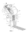
- the figure 1 discloses a general view of a channeled guiding device according to the invention in a packaging machine seen in cutaway, casings which enclose the movement transmission members controlling the moving parts, as well as protective plates which participate in the channeling of the tablets, having been removed to reveal the internal part of said device.
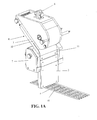
- the Figure 1A corresponds to the figure 1 , but the housings and plates are in place to show the external general appearance of the device.
- Protective housings or plates can enclose particular moving mechanical parts and protect these parts of the dust that can be generated by the units to be packaged and facilitate cleaning.
- plates are placed above the grooves of the channels to allow in particular to maintain the tablets and form a complete entity of pipe for their transport, and also to protect them.
- the feeding device comprises an arrival zone A of tablets and a pipe ramp R provided with longitudinal channels 31, 32 for guiding the tablets.
- This ramp is divided into two ramps, an upstream ramp 1 and a downstream ramp 2.
- the upstream ramp 1 which is transversely movable, comprises two parts, an upper portion 10 slightly inclined and a tilting portion 11 more inclined.
- the upstream ramp comprises upstream channels 31, all similar, which are in the form of grooves hollowed in the mass of the ramp, which is usually made of metal or a plastic material of food grade.
- the upper part 10 is located at a zone B accumulation of tablets.
- the downstream ramp 2 disposed vertically, comprises five downstream guide channels 32, the same number as that of the cells 41 to be filled simultaneously, that is to say the same number of rows of cells in scrolling of the cellular tape. She is fixed.
- the downstream channels 32 are similar in the form of grooves dug in the metal of the ramp and covered with a plate (of metal or plastic food for example) forming the top of the channel.
- the upstream ramp 1 comprises ten upstream channels 31 side by side.
- the upstream channels 31 of the upstream ramp 1 are therefore in double number of the downstream channels 32 of the downstream ramp 2.
- the channels 32 of the downstream ramp 2 are of the same width as that of the upstream channels 31 of the upstream ramp 1 but they are more spaced.
- the distance between the centers of the downstream channels 32 is twice the distance between the centers of the upstream channels 31.
- the upstream ramp 1 thus associates two upstream channels 31, which will also be called paired, paired or matched.
- the tablets come from a hopper forming a feed tank located above the packaging machine, from which they fall through a feed pipe (not shown) on the slightly inclined plane of the arrival zone A.
- a level detector 6 is connected to the feed hopper to control the supply of tablets , to allow it or not.
- Tablets entering the upstream channels 31 will then flow by gravity following these upstream channels 31 of the upstream ramp 1, which is in inclined plane, and continue their journey in the downstream channels 32 of the downstream ramp 2, connected alternately to one channel on two of the upstream channels 31.
- the tablets then fall into the five cells 41 of the cellular strip 4 which scrolls underneath.
- the spacing between the downstream channels 32 is such as to shift the channels 31 of the upstream ramp 1 by a distance equal to that of the spacing between two upstream channels 31 so that the coupled channels 31 alternatively feed each channel 32 downstream as explained below with reference to Figures 4A and 4B .
- a housing 7 comprises various actuators of the guide device, in particular an end-of-travel adjustment bar for the upstream ramp.
- This bar 8 is not visible on the Figure 1A . It is described more fully in Figures 4A and 4B .
- the housing 7 also comprises the control means for the means for stopping the tablets, which are made in the case described in the form of a stopper part, not visible on the Figure 1A , controlled to block the circulation of the tablets before a transverse displacement of the upstream ramp. It also includes the actuator that allows the transverse movement of the upstream ramp.
- an opto-electronic cell located at the top of the downstream ramp is configured to detect the filling level of the downstream channels.
- the figure 2 is a sectional view of the device of the figure 1 , illustrated supplied with tablets in the plane of an upstream channel 31 and a downstream channel 32 connected to each other.
- tablets C being represented in addition.
- the tablet holder part 9 which is connected to the upstream ramp 1. This part is actuated to block the descent of the tablets C at their passage of the channels 31 of the upstream ramp 1 to the channels 32 of the downstream ramp 2, before any transverse displacement of the upstream ramp 1, so as not to crush, section, or block tablets at this level during the displacement of the upstream ramp.
- This stopper part 9 is actuated by a pneumatic cylinder, called here thrust cylinder V, or locking cylinder, which pushes this piece to the upstream channels to close them. More precisely piece 9 is here realized in the form of a bar, which carries fingers 91 in number equal to that of the number of channels 31 of the upstream ramp 1 to close, so here ten. These fingers 91 are of a width less than that of each channel 31; they are protruding outside the room 9. As explained below these fingers 91 will be introduced into the upstream channels without fully touching the bottom of the groove, to block the tablets without crushing, cutting, or damaging d in any way.
- a pneumatic cylinder called here thrust cylinder V, or locking cylinder
- the Figures 3A and 3B are two views, in perspective, of the retaining piece 9, observed from two different angles.
- the fingers 91 are flexible and / or compressible. They are notably realized, as illustrated by the figure 3A , in the form of helical springs, for example stainless steel, bearing between two plates. Suitable resilient fingers may also be spring blades, which are illustrated on the figure 3A coming out obliquely from the box of room 9. These fingers have the role of closing the channels by blocking the passage of tablets. Their elasticity allows a modulation of their pressure and their depth of penetration into the channels, which prevents them from damaging the tablets that would still be present when the stopper part 9 is put into action.
- FIGS. 4A and 4B represent the guide device with the upstream ramp 1 of the ramp R moved respectively to the right and to the left, to explain the transverse movement of this upstream ramp 1 relative to the axis of symmetry of the ramp appearing in dotted lines in the figures.
- the twinned channels 31 of the upstream ramp 1, in order to better explain the operation of the device, are distinguished and named 31d and 31g respectively for the right channel and the left channel.
- the bar 8 for adjusting the transverse stroke of the upstream ramp 1 is shown at the top of the Figures 4A and 4B for the understanding of the displacement of the upstream ramp 1 of the device but in practice it is located preferentially in the housing 7.
- An opto-electronic presence detection device 5 comprising an emitting cell 51 and a receiving cell 52 disposed on either side of the downstream ramp 2 and as high as possible at the beginning (at their entry) of the downstream channels 32 of the downstream ramp 2, to detect the presence or absence of tablets at the top of these downstream channels 32 and thus know whether the upstream ramp 1 can be moved, without damaging the tablets that would be at the top of the channels.
- the distance between the cell 5 (here the cells 51, 52) and the inlet of the downstream channels 32 (at the top of the downstream ramp 2) must be smaller than the size of the tablets.
- the ten upstream channels 31 of the upstream ramp 1 are shifted to the left and the tablets therefore flow from the right channels 31d into the downstream channels 32.
- the tablets in the left upstream channels 31g are blocked by the solid upper part of the downstream ramp 32.
- the guide device according to the invention therefore makes it possible to move the upstream ramp 1 from left to right so as to feed the downstream channels 32 according to the principle which will be described below.
- the tablets entered in the upstream channels 31 of the upstream ramp 1 are stopped at the outlet of the upstream channels 31 by sending an automated signal to the thrust cylinder of the stop means 9 to the upstream channels 31 so that the fingers 91 stop the progress of the tablets that run in each upstream channel. Then, the presence of tablets C at the top (at the inlet) of the downstream channels 32 of the downstream ramp 2 with the cell 5 is detected in order to determine whether the displacement cross section of the upstream ramp may be allowed.
- the information is used to control another jack W to move the upstream ramp 1 transversely to the right, by a distance equal to the distance between the centers of two twinned channels 31 , so as to put the left channel 31g of the upstream ramp in connection with the corresponding downstream channel 32.
- the limit switch 820 detects that the upstream ramp 1 has touched the right stop 810 and controls the thrust cylinder V to release the stop means 9 and thus let the tablets run to fill the downstream channels 32 and flow into the cells 41 of the honeycomb strip which runs under the downstream channels 32.
- the flow of the tablets C is again stopped as in the preceding step, and the presence of tablets C at the inlet of the downstream channels 32 of the downstream ramp 2 is detected as before. If no tablet is detected at the top of Channels 32, a signal is sent again to said other cylinder W to laterally move the upstream ramp 1 to the left in order to put the second right upstream channel 31 d in connection with the channel 32 and fill it.
- the limit switch of the upstream ramp 1 is also detected by an end-of-travel detector 821 when it comes against the left stop 811.
- the procedure is repeated periodically, by providing a movement back and forth of the upstream ramp 1, each go and each return being set by a programmed actuation of the tablet holding part 9, for example both. seconds.
- This actuation of the retaining piece could also be triggered by a signal related to a detection of the degree of filling of each of the downstream channels. Such detection can be done for example with the aid of a camera pointed at the downstream channels.
- the invention allows the downstream channels 32 are always properly filled, enough so that the cells 41 are all filled with tablets in good condition, even when the longitudinal scrolling speed of the blister strip is substantially increased.
- tests have revealed a flow rate of about 15 tablets per second in each downstream channel, ie a conditioning rate of 900 to 1000 tablets per minute, whereas in the prior art, the conditioning rate was only 700 tablets per minute.
- the rate of conditioning of the tablets in the cells is increased, for example by at least 20 to more than 40%.
- channel grooves is typical of each type of unit to be packaged, be it long, oblong tablets, capsules or capsules, etc. These are so-called format parts, which are interchangeable in the same packaging machine.
- the stroke adjustment bar of the upstream ramp is a part in the format, the realization of which depends on the width, the number and the distribution of the downstream channels in correspondence with the receiving cells in the moving strip.
- the coin hold tablet is also a coin format.
- the invention has been described for a ramp with an inclined portion and a vertical portion.
- the invention is not limited to this type of ramp. It could also be a vibrating ramp slightly inclined and without change of inclination or low change of slope, the tablets being routed in the distribution channels mainly through vibration. It can also be a combined ramp comprising a horizontal vibrating ramp and a vertical non-vibrating ramp. And in the downstream ramp, the channels can be rectilinear rather than curved to end at an angle in the cells as shown in the diagram. figure 1 .
- the invention is not limited to the modes of implementation which have been specifically described and represented, and that it extends on the contrary to any variant passing through equivalent means.
Abstract
Description
La présente invention concerne le domaine du conditionnement de comprimés sous blister et, plus particulièrement, les dispositifs de distribution de comprimés dans une bande alvéolée de conditionnement qui procèdent par guidage canalisé des comprimés dans des canaux les conduisant dans les alvéoles de ladite bande, celle-ci étant continue et entraînée à défiler en dessous du dispositif de distribution. L'invention concerne plus spécifiquement la réalisation des moyens de canalisation à canaux multiples servant au guidage des comprimés jusqu'à leur dépôt dans les alvéoles d'une bande alvéolée entraînée en défilement dans une machine de conditionnement, ainsi que la conception et la réalisation des moyens associés utiles au fonctionnement de l'ensemble.The present invention relates to the field of the packaging of blister packs and, more particularly, the tablet dispensing devices in a blister pack of conditioning which proceed by channeling the tablets into channels leading them into the cells of said strip, it being continuous and driven to scroll below the dispensing device. The invention relates more specifically to the realization of the multi-channel channeling means for guiding the tablets until they are deposited in the cells of a hollow strip driven in a packaging machine, and the design and production of the associated means useful to the operation of the whole.
On entend ici par comprimés, toutes unités sous forme discrète qui peuvent être des comprimés de toute forme (ronde, oblongue, etc.), mais également des gélules, des capsules, ou tout autres types d'unités qui doivent être mises en place dans les différentes alvéoles d'une bande alvéolée pour être conditionnées en plaquettes. L'invention s'applique plus particulièrement, mais non limitativement, dans le domaine pharmaceutique.The term "tablets" is intended here to mean any units in discrete form which may be tablets of any shape (round, oblong, etc.), but also capsules, capsules, or any other type of unit which must be put into place in the different cells of a blister strip to be packaged into platelets. The invention applies more particularly, but not exclusively, in the pharmaceutical field.
Il existe de nombreuses installations de conditionnement permettant de disposer des comprimés ou objets similaires dans les alvéoles d'une bande alvéolée en défilement en dessous d'un dispositif de distribution amenant les comprimés. Les bandes alvéolées, une fois les comprimés déposés dans les alvéoles, reçoivent à un autre poste, une pellicule de fermeture (par exemple un film protecteur d'aluminium), puis elles sont découpées en plaquettes. Les bandes alvéolées sont généralement faites par thermoformage des alvéoles dans une feuille en matière synthétique.There are many packaging facilities for disposing tablets or similar objects in the cells of a moving honeycomb strip below a dispensing device bringing the tablets. The blister strips, once the tablets are deposited in the cells, receive at another station a closure film (for example an aluminum protective film), and then they are cut into platelets. The honeycomb strips are generally made by thermoforming the cells in a sheet of synthetic material.
Parmi ces installations, l'invention s'intéresse plus spécifiquement à celles dans lesquelles la distribution des comprimés implique le guidage des comprimés le long de rampes à canaux multiples, dans des dispositifs dits de distribution canalisée, ou de guidage canalisé. Parmi les dispositifs de guidage canalisé, on rencontre trois types principaux de rampes, suivant que le cheminement des comprimés, en série les uns après les autres, dans leurs canaux de guidage respectifs, est assuré uniquement par gravité, grâce à l'inclinaison de la l'orientation de la rampe dans l'espace, ou qu'il est assuré par mise en vibration de la rampe, étant entendu que les deux solutions sont souvent appliquées ensemble.Among these installations, the invention is more specifically concerned with those in which the distribution of tablets involves guiding the tablets along multi-channel ramps, in so-called channelized distribution devices, or channelized guidance devices. Among the ducted guide devices, there are three main types of ramps, according to which the path of the tablets, in series one after the other, in their respective guide channels, is provided solely by gravity, thanks to the inclination of the the orientation of the ramp in space, or that it is provided by vibrating the ramp, it being understood that the two solutions are often applied together.
Le problème principal de ces rampes de distribution canalisée vient de la vitesse d'introduction des comprimés dans les canaux, qui est insuffisante par rapport à ce que peuvent permettre la vitesse de cheminement des comprimés une fois dans les canaux et la vitesse de défilement de la bande alvéolée. Les comprimés sont généralement présentés en vrac au départ d'une rampe inclinée et/ou vibrante, dans un réservoir d'alimentation où ils s'accumulent dans une zone où ils sont brassés et refoulés, par exemple par une brosse rotative à pales flexibles qui les fait entrer dans l'embouchure des canaux de distribution. L'introduction des comprimés peut aussi se faire uniquement par vibration. On comprend que cette introduction peut être irrégulière et créer une alimentation des canaux insuffisante en comprimés. Il peut y avoir des canaux insuffisamment remplis et, par conséquent, pour palier ce problème, il faut utiliser une vitesse de défilement de la bande alvéolée inférieure à ce qu'elle pourrait être si les canaux étaient toujours correctement remplis. Manifestement, l'industrie est en demande pour des moyens permettant d'accélérer la cadence de remplissage des alvéoles.The main problem of these channelized distribution ramps comes from the speed of introduction of the tablets into the channels, which is insufficient compared to what can allow the speed of movement of the tablets once in the channels and the speed of scrolling of the cellular tape. The tablets are generally presented in bulk from an inclined and / or vibrating ramp in a feed tank where they accumulate in an area where they are stirred and discharged, for example by a rotating brush with flexible blades which brings them into the mouth of the distribution channels. The introduction of tablets can also be done only by vibration. It is understood that this introduction may be irregular and create an insufficient supply of channels in tablets. There may be insufficiently filled channels and, therefore, to overcome this problem, a slotted tape speed of less than what it could be if the channels were still correctly filled should be used. Clearly, the industry is in demand for ways to accelerate cell filling rates.
Le but de l'invention est donc de remédier à ce problème et d'augmenter la cadence de remplissage des alvéoles en augmentant le débit global de comprimés sans nuire à la stabilité d'alimentation et à la régularité du remplissage des bandes.The object of the invention is therefore to remedy this problem and to increase the filling rate of the cells by increasing the overall flow of tablets without affecting the feed stability and the regularity of the filling of the strips.
L'invention propose à cette fin de scinder la rampe en deux parties, une partie amont où sont introduits les comprimés, de manière en soi classique à partir d'un réservoir d'alimentation en vrac, et une partie aval d'où sortent les comprimés pour être déposés dans les alvéoles de la bande réceptrice, et en prévoyant de munir la partie de rampe amont de canaux longitudinaux en nombre multiple du nombre de canaux utiles que la partie de rampe aval comporte. De manière plus précise, il est avantageusement prévu qu'à chaque canal aval utile au remplissage d'une colonne d'alvéoles dans la bande en défilement sous la rampe aval, il soit associé plusieurs canaux de la rampe amont, au moins au nombre de deux pour chaque canal aval, dans une disposition permettant de les mettre à tour de rôle en communication avec le canal correspondant de la rampe aval. Pour permettre la commutation, la rampe amont est réalisée mobile transversalement. La direction transversale est ici exprimée par rapport à la direction longitudinale des canaux, c'est-à-dire, en général, également par rapport à la direction de défilement de la bande alvéolée dans une machine de conditionnement. Par ailleurs, l'amont et l'aval sont bien évidemment définis par rapport au sens d'écoulement des comprimés vers les alvéoles.The invention proposes for this purpose to split the ramp into two parts, an upstream portion where the tablets are introduced, in a conventional manner from a bulk feed tank, and a part downstream from which the tablets come out to be deposited in the cells of the receiver band, and by providing to provide the upstream ramp portion of longitudinal channels in a number multiple of the number of useful channels that the downstream ramp portion has. More specifically, it is advantageously provided that for each downstream channel useful for filling a column of cells in the strip running under the downstream ramp, several channels of the upstream ramp are associated, at least in number of two for each downstream channel, in a disposition to put them in turn in communication with the corresponding channel of the downstream ramp. To enable switching, the upstream ramp is made mobile transversely. The transverse direction is here expressed relative to the longitudinal direction of the channels, that is to say, in general, also with respect to the direction of travel of the blister strip in a packaging machine. Furthermore, upstream and downstream are obviously defined with respect to the direction of flow of the tablets to the cells.
L'art antérieur en la matière est illustré notamment par le document de brevet
Par rapport à un tel art antérieur, les objectifs de la présente invention sont atteints par les caractéristiques qui font l'objet de la revendication 1 à titre principal, par les autres revendications à titre secondaire, ainsi que par les explications à leur sujet qui ressortiront de la description ci-après d'un mode de mise en oeuvre de l'invention illustré par les figures.With respect to such a prior art, the objectives of the present invention are achieved by the features which are the subject of
Cette description illustre l'utilisation du dispositif de distribution dans un procédé de conditionnement de comprimés par guidage canalisé des comprimés jusqu'à leur dépôt dans les alvéoles d'une bande alvéolée en défilement, suivant lequel on met en oeuvre le dispositif de distribution canalisée avec ses canaux de guidage des comprimés et ses moyens de permutation des connexions entre canaux amont et canaux aval par déplacement transversal de la rampe amont par rapport à la rampe aval. Suivant ce procédé on commande le déroulement automatique des différentes étapes de fonctionnement d'un cycle périodique qui est décrit ci-après en se plaçant dans le cas particulier d'une permutation des connexions entre deux canaux amont alternativement (ce cas correspondant également à une forme de mise en oeuvre industrielle préférée, ne serait-ce que pour sa simplicité de construction).
- 1. On arrête l'écoulement des comprimés à la sortie des canaux de la rampe amont par envoi d'un signal automatisé vers un vérin qui pousse les moyens d'arrêt des comprimés vers les canaux amont ;
- 2. On détecte la présence de comprimés à l'entrée des canaux de la rampe aval afin de déterminer si le déplacement transversal de la rampe amont est autorisé ;
- 3. Si aucun comprimé n'est présent à l'entrée des canaux, on envoie alors un signal de commande d'un autre vérin, par exemple, pour déplacer la rampe amont transversalement dans son débattement vers l'un des côtés et mettre en connexion chaque canal aval avec un premier des canaux amont qui lui sont associés ;
- 4. Quand le détecteur de fin de course signale que la rampe amont a atteint une butée présente sur ledit côté, on commande le vérin des moyens d'arrêt de manière à libérer le passage des comprimés dans chaque canal amont et à laisser ainsi les comprimés remplir les canaux
aval et s'écouler jusque dans les alvéoles de la bande alvéolée en défilement sous les canaux aval ; - 5. On laisse la circulation des comprimés s'effectuer par les passages connectés jusqu'au déclenchement d'une nouvelle opération de permutation des connexions, laquelle peut être déterminée notamment, de manière automatique, soit par un délai de temporisation réglé par avance, soit suite à la détection d'un degré de remplissage insuffisant des canaux aval en cours d'utilisation ;
- 6. On commande alors les moyens d'arrêt pour un blocage temporaire de la circulation des comprimés en amont comme à l'étape 1 ;
- 7. On détecte comme à l'étape 2, la présence éventuelle de comprimés à l'entrée des canaux aval de la rampe aval ;
- 8. Si aucun comprimé n'est détecté à l'entrée des canaux, on commande le vérin de déplacement de la rampe amont pour déplacer celle-ci transversalement vers le côté opposé à celui mentionné pour l'étape 3 et mettre chaque canal aval en communication avec l'autre canal amont ;
- 9. Comme à l'étape 5, on détecte la fin de course de la rampe amont lorsqu'elle a touché la butée dudit côté opposé et on commande de la même manière le relâchement des moyens d'arrêt des comprimés pour laisser à nouveau les comprimés s'acheminer pour remplir les canaux et s'écouler jusque dans les alvéoles de la bande alvéolée en défilement sous les canaux aval.
- 1. The flow of tablets is stopped at the outlet of the channels of the upstream ramp by sending an automated signal to a jack which pushes the means for stopping tablets to the upstream channels;
- 2. The presence of tablets at the inlet of the downstream boom channels is detected to determine whether transversal displacement of the upstream boom is allowed;
- 3. If no tablet is present at the entrance of the channels, then a control signal is sent from another cylinder, for example, to move the upstream ramp transversely in its travel towards one of the sides and put in connecting each downstream channel with a first of the upstream channels associated therewith;
- 4. When the limit switch signals that the upstream ramp has reached a stop present on said side, the cylinder of the stop means is controlled so as to release the passage of the tablets in each upstream channel and thus to leave the tablets fill the channels
downstream and flow into the alveoli of the cellular strip running under the downstream channels; - 5. The circulation of the tablets is allowed to take place through the connected passages until a new operation of permutation of the connections is triggered, which can be determined in particular, automatically, either by a delay time set in advance, or following the detection of an insufficient degree of filling of the downstream channels in use;
- 6. The stop means is then controlled for temporarily blocking the circulation of the tablets upstream as in
step 1; - 7. As in
step 2, the presence of tablets at the inlet of the downstream channels of the downstream ramp is detected; - 8. If no tablet is detected at the entrance of the channels, the displacement cylinder of the upstream ramp is controlled to move it transversely to the opposite side to that mentioned for step 3 and to put each downstream channel into communication with the other upstream channel;
- 9. As in
step 5, the end of travel of the upstream ramp is detected when it has touched the abutment of said opposite side and the release means of stopping the tablets are also controlled in the same way to leave the The tablets run to fill the channels and flow into the alveoli of the honeycomb strip running under the downstream channels.
Après un délai d'écoulement normal comme à l'étape 5, on reprend le cycle en répétant, chaque fois qu'une permutation est déclenchée, la série des étapes 1 à 4 ou 6 à 9 qui assurent la synchronisation du déplacement de la rampe amont avec l'absence de comprimés dans la zone du plan de jonction entre les deux rampes, ce pendant toute la durée de remplissage des alvéoles de la bande alvéolée en défilement. Les conditions de remplissage sont optimales, dans la mesure où il est facile d'assurer que les opérations automatiques de permutation soient rapides au regard de la longueur de la rampe aval.After a normal flow delay as in
Selon un mode particulier de mise en oeuvre de l'invention, le procédé de conditionnement des comprimés est tel qu'il comprend avant l'étape 1, une étape selon laquelle on déverse des comprimés depuis un réservoir d'alimentation sur une zone d'arrivée dudit dispositif de guidage, les comprimés s'écoulant par gravité et/ou vibration jusqu'à une zone d'accumulation contre une brosse rotative à pales qui refoule et brasse les comprimés afin de les faire entrer dans les canaux de guidage de la rampe amont, le niveau d'accumulation en zone d'accumulation étant détecté par un détecteur, en particulier qui peut être optique, afin de commander l'envoi d'un signal pour stopper ou enclencher le déversement en zone d'arrivée.According to one particular embodiment of the invention, the method of packaging the tablets is such that it comprises, before
L'invention sera maintenant plus complètement décrite dans le cadre de caractéristiques préférées et de leurs avantages, en faisant référence aux
- la
figure 1 est une vue générale en perspective et en écorché du dispositif de guidage canalisé selon l'invention dans une machine de conditionnement de comprimés, - la
figure 1A est une vue du dispositif selon lafigure 1 , - la
figure 2 est une vue en coupe du dispositif de lafigure 1 , approvisionné en comprimés, suivant le plan d'un canal amont et un canal aval connectés ensemble; - les
figures 3A et 3B sont deux vues en perspective de moyens d'arrêt des comprimés dans le dispositif selon l'invention, - et les
figures 4A et4B illustrent schématiquement le dispositif en vue de face, en écorché, et en élévation.
- the
figure 1 is a general perspective view and cut away of the channeled guiding device according to the invention in a tablet packaging machine, - the
Figure 1A is a view of the device according to thefigure 1 , - the
figure 2 is a sectional view of the device of thefigure 1 , supplied with tablets, according to the plan of an upstream channel and a downstream channel connected together; - the
Figures 3A and 3B are two perspective views of means for stopping the tablets in the device according to the invention, - and the
Figures 4A and4B schematically illustrate the device in front view, cutaway, and elevation.
La
La
Le dispositif d'alimentation comporte une zone d'arrivée A des comprimés et une rampe de canalisation R munie de canaux longitudinaux 31,32 destinés au guidage des comprimés. Cette rampe est scindée en deux rampes, une rampe amont 1 et une rampe aval 2. La rampe amont 1, qui est mobile transversalement, comporte deux parties, une partie supérieure 10 légèrement inclinée et une partie répartiteur 11 plus inclinée. Dans chacune de ses deux parties10 et 11, la rampe amont comporte des canaux amont 31, tous semblables, qui sont sous forme de rainures creusées dans la masse de la rampe, qui est en général en métal ou en une matière plastique de qualité alimentaire. La partie supérieure 10 se situe au niveau d'une zone B d'accumulation des comprimés.The feeding device comprises an arrival zone A of tablets and a pipe ramp R provided with
La rampe aval 2, disposée à la verticale, comporte cinq canaux de guidage aval 32, soit le même nombre que celui des alvéoles 41 à remplir simultanément, c'est-à-dire le même nombre de rangées d'alvéoles en défilement de la bande alvéolée. Elle est fixe. Les canaux aval 32 sont semblables, sous forme de rainures creusées dans le métal de la rampe et recouvertes d'une plaque (en métal ou plastique alimentaire par exemple) formant le dessus du canal.The
La rampe amont 1 comporte dix canaux amont 31 côte à côte.The
Les canaux amont 31 de la rampe amont 1 sont donc en nombre double des canaux aval 32 de la rampe aval 2. Les canaux 32 de la rampe aval 2 sont de la même largeur que celle des canaux amont 31 de la rampe amont 1 mais ils sont plus espacés. La distance d'entraxe des canaux aval 32 est le double de la distance d'entraxe des canaux amont 31. A chaque canal 32 de la rampe aval, la rampe amont 1 associe donc deux canaux amont 31, que l'on qualifiera aussi de jumelés, couplés ou appariés.The
Les comprimés proviennent d'une trémie formant réservoir d'alimentation située au-dessus de la machine de conditionnement, d'où ils tombent par un tuyau d'amenée (non représenté) sur le plan légèrement incliné de la zone d'arrivée A.The tablets come from a hopper forming a feed tank located above the packaging machine, from which they fall through a feed pipe (not shown) on the slightly inclined plane of the arrival zone A.
Ces comprimés glissent alors vers la rampe R de canalisation pour s'accumuler dans la partie B de ce dispositif, où, ici au moyen d'une brosse rotative P à pales flexibles 5, qui tourne dans le sens des aiguilles d'une montre lorsqu'on regarde la
Les comprimés entrés dans les canaux amont 31 vont alors s'écouler par gravité en suivant ces canaux amont 31 de la rampe amont 1, qui est en plan incliné, et poursuivre leur cheminent dans les canaux aval 32 de la rampe aval 2, connectés alternativement à un canal sur deux des canaux amont 31. Les comprimés tombent alors dans les cinq alvéoles 41 de la bande alvéolée 4 qui défile en dessous.Tablets entering the
L'espacement entre les canaux aval 32 est tel qu'il permet de décaler les canaux 31 de la rampe amont 1 d'une distance égale à celle de l'entraxe entre deux canaux amont 31 afin que les canaux couplés 31 alimentent alternativement chaque canal 32 en aval comme cela est expliqué plus loin par référence aux
Un boîtier 7 comporte divers actionneurs du dispositif de guidage, en particulier une barrette de réglage de fin de course pour la rampe amont. Cette barrette 8 n'est pas visible sur la
La
Sur cette
Cette pièce arrêtoir 9 est actionnée par un vérin pneumatique, appelé ici vérin de poussée V, ou vérin de blocage, qui pousse cette pièce vers les canaux amont pour les fermer. Plus précisément la pièce 9 est ici réalisée sous la forme d'une barre, qui porte des doigts 91 en nombre égal à celui des nombres de canaux 31 de la rampe amont 1 à fermer, donc ici dix. Ces doigts 91 sont d'une largeur inférieure à celle de chaque canal 31 ; ils dépassent à l'extérieur de la pièce 9. Comme explicité ci-après ces doigts 91 vont être introduits dans les canaux amont sans totalement toucher le fond de la rainure, pour bloquer les comprimés sans les écraser, les couper, ou les abîmer d'une quelconque manière.This
Les
Les
Les canaux jumelés 31 de la rampe amont 1, afin de mieux expliquer le fonctionnement du dispositif, sont distingués et nommés 31d et 31 g respectivement pour le canal de droite et le canal de gauche.The twinned
La barrette 8 de réglage de course transversale de la rampe amont 1 est représentée en haut des
Sur la
Un dispositif de détection de présence de opto-électronique 5, comprenant une cellule émettrice 51 et une cellule réceptrice 52 disposées de part et d'autre de la rampe aval 2 et le plus haut possible au début (à leur entrée) des canaux aval 32 de la rampe aval 2, permet de détecter la présence ou non de comprimés en haut de ces canaux aval 32 et de savoir ainsi si la rampe amont 1 pourra être déplacée, sans abîmer les comprimés qui seraient en haut des canaux. De préférence la distance entre la cellule 5 (ici les cellules 51, 52) et l'entrée des canaux aval 32 (en haut de la rampe aval 2) doit être inférieure à la taille des comprimés.An opto-electronic
Sur la
Le dispositif de guidage selon l'invention permet donc de déplacer la rampe amont 1 de gauche à droite de manière à alimenter les canaux aval 32 selon le principe qui va être décrit ci-après.The guide device according to the invention therefore makes it possible to move the
Les comprimés entrés dans les canaux amont 31 de la rampe amont 1 sont arrêtés à la sortie des canaux amont 31 par envoi d'un signal automatisé au vérin de poussée des moyens d'arrêt 9 vers les canaux amont 31 afin que les doigts 91 stoppent la progression des comprimés qui cheminent dans chaque canal amont. Ensuite, on détecte la présence de comprimés C en haut (à l'entrée) des canaux aval 32 de la rampe aval 2 avec la cellule 5 afin de déterminer si le déplacement transversal de la rampe amont peut être autorisé. Si aucun comprimé n'est présent dans les canaux aval, l'information est utilisée pour commander un autre vérin W pour déplacer la rampe amont 1 transversalement vers la droite, d'une distance égale à la distance d'entraxe de deux canaux jumelés 31, de manière à mettre le canal gauche 31g de la rampe amont en connexion avec le canal aval 32 correspondant. On détecte par le détecteur de fin de course 820 que la rampe amont 1 a touché la butée droite 810 et commande le vérin de poussée V pour relâcher les moyens d'arrêt 9 et ainsi laisser les comprimés s'acheminer pour remplir les canaux aval 32 et s'écouler jusque dans les alvéoles 41 de la bande alvéolée qui défile sous les canaux aval 32.The tablets entered in the
On arrête à nouveau comme à l'étape précédente l'écoulement des comprimés C puis on détecte comme précédemment la présence de comprimés C à l'entrée des canaux aval 32 de la rampe aval 2. Si aucun comprimé n'est détecté en haut des canaux 32, on envoie à nouveau un signal audit autre vérin W pour déplacer latéralement la rampe amont 1 vers la gauche afin de mettre le deuxième canal amont droite 31 d en connexion avec le canal 32 et le remplir. On détecte également la fin de course de la rampe amont 1 par un détecteur de fin de course 821 lorsqu'on arrive contre la butée gauche 811.The flow of the tablets C is again stopped as in the preceding step, and the presence of tablets C at the inlet of the
On renouvelle la procédure de manière périodique, en assurant un mouvement de va-et-vient de la rampe amont 1, chaque aller et chaque retour étant réglés par une mise en action programmée de la pièce arrêtoir de comprimés 9, par exemple toutes les deux secondes. Cette mise en action de la pièce arrêtoir pourrait être aussi déclenchée par un signal lié à une détection du degré de remplissage de chacun des canaux aval. Une telle détection peut se faire par exemple à l'aide d'une caméra pointée sur les canaux aval.The procedure is repeated periodically, by providing a movement back and forth of the
On comprend qu'au total, l'invention permet que les canaux aval 32 soient toujours correctement remplis, suffisamment pour que les alvéoles 41 soient toutes remplies de comprimés en bon état, même quand on augment sensiblement la vitesse de défilement longitudinale de la bande alvéolée. Pour un type de comprimés donné, dans le cas d'un dispositif de canalisation à rampe inclinée et à brosse à pales souples comme décrit ci-dessus, des tests ont révélé un débit d'environ 15 comprimés par seconde dans chaque canal aval, soit une cadence de conditionnement de 900 à 1000 comprimés par minute, alors que dans l'art antérieur, la cadence de conditionnement n'était que de 700 comprimés par minute.It is understood that in total, the invention allows the
La description qui précède explique clairement comment l'invention permet d'atteindre les objectifs qu'elle s'est fixés. En particulier, selon l'invention la cadence de conditionnement des comprimés dans les alvéoles est augmentée, par exemple d'au moins 20 à plus de 40 %.The foregoing description clearly explains how the invention achieves the goals it has set for itself. In particular, according to the invention the rate of conditioning of the tablets in the cells is increased, for example by at least 20 to more than 40%.
La forme des rainures des canaux est typique de chaque type d'unités à conditionner, que ce soit des comprimés longs, oblongs, des capsules ou des gélules, etc. Ce sont donc ce qu'on appelle des pièces au format, qui sont interchangeables dans la même machine de conditionnement. De même, la barrette de réglage de course de la rampe amont est une pièce au format, dont la réalisation dépend de la largeur, du nombre et de la répartition des canaux aval en correspondance avec les alvéoles réceptrices dans la bande en défilement. La pièce arrêtoir des comprimés est aussi une pièce au format.The shape of channel grooves is typical of each type of unit to be packaged, be it long, oblong tablets, capsules or capsules, etc. These are so-called format parts, which are interchangeable in the same packaging machine. Similarly, the stroke adjustment bar of the upstream ramp is a part in the format, the realization of which depends on the width, the number and the distribution of the downstream channels in correspondence with the receiving cells in the moving strip. The coin hold tablet is also a coin format.
L'invention a été décrite pour une rampe avec une partie inclinée et une partie verticale. Toutefois l'invention n'est pas limitée à ce type de rampe. Il pourrait s'agir aussi d'une rampe vibrante légèrement inclinée et sans changement d'inclinaison ou à faible changement de pente, les comprimés étant acheminés dans les canaux de distribution principalement grâce aux vibrations. Il peut s'agir aussi d'une rampe combinée comportant une rampe vibrante horizontale et une rampe non vibrante verticale. Et dans la rampe aval, les canaux peuvent être rectilignes plutôt que courbés pour aboutir en biais dans les alvéoles comme illustrés sur la
Claims (15)
Priority Applications (2)
| Application Number | Priority Date | Filing Date | Title |
|---|---|---|---|
| EP20100013547 EP2441682B1 (en) | 2010-10-12 | 2010-10-12 | Device for channelled distribution of tablets and method for implementing same |
| ES10013547T ES2416492T3 (en) | 2010-10-12 | 2010-10-12 | Channeled tablet distribution device and procedure for its realization |
Applications Claiming Priority (1)
| Application Number | Priority Date | Filing Date | Title |
|---|---|---|---|
| EP20100013547 EP2441682B1 (en) | 2010-10-12 | 2010-10-12 | Device for channelled distribution of tablets and method for implementing same |
Publications (2)
| Publication Number | Publication Date |
|---|---|
| EP2441682A1 true EP2441682A1 (en) | 2012-04-18 |
| EP2441682B1 EP2441682B1 (en) | 2013-04-03 |
Family
ID=43661998
Family Applications (1)
| Application Number | Title | Priority Date | Filing Date |
|---|---|---|---|
| EP20100013547 Active EP2441682B1 (en) | 2010-10-12 | 2010-10-12 | Device for channelled distribution of tablets and method for implementing same |
Country Status (2)
| Country | Link |
|---|---|
| EP (1) | EP2441682B1 (en) |
| ES (1) | ES2416492T3 (en) |
Cited By (9)
| Publication number | Priority date | Publication date | Assignee | Title |
|---|---|---|---|---|
| CN102941940A (en) * | 2012-11-21 | 2013-02-27 | 温州海派机械科技有限公司 | Feeding mechanism of battery packing machine |
| CN103224057A (en) * | 2012-08-30 | 2013-07-31 | 石松泉 | Simple fake nail piece automatic blanking and overlapping device |
| US20150027851A1 (en) * | 2012-03-14 | 2015-01-29 | I.M.A. Industria Macchine Automatiche S.P.A. | Distributor unit |
| US9150119B2 (en) | 2013-03-15 | 2015-10-06 | Aesynt Incorporated | Apparatuses, systems, and methods for anticipating and delivering medications from a central pharmacy to a patient using a track based transport system |
| CN105083604A (en) * | 2015-08-27 | 2015-11-25 | 钦州市奥佳华新能源科技有限公司 | Automatic button battery packaging device |
| US9511945B2 (en) | 2012-10-12 | 2016-12-06 | Aesynt Incorporated | Apparatuses, systems, and methods for transporting medications from a central pharmacy to a patient in a healthcare facility |
| EP3318497A1 (en) * | 2016-11-07 | 2018-05-09 | Mediseal GmbH | Solid pharmaceuticals feeder for a blister machine |
| CN108860790A (en) * | 2018-05-31 | 2018-11-23 | 中国人民解放军陆军军医大学第附属医院 | Medical nursing equipment |
| CN109911286A (en) * | 2019-03-28 | 2019-06-21 | 惠州市三协精密有限公司 | Betel nut blanking loading mechanism |
Families Citing this family (1)
| Publication number | Priority date | Publication date | Assignee | Title |
|---|---|---|---|---|
| RU2701344C1 (en) * | 2019-04-11 | 2019-09-25 | Юрий Николаевич Сушков | Device for turning of objects moving by conveyor, during their transfer to receiving conveyor or working table |
Citations (5)
| Publication number | Priority date | Publication date | Assignee | Title |
|---|---|---|---|---|
| US2845759A (en) * | 1955-09-26 | 1958-08-05 | Us Automatic Box Machinery Co | Method of and machine for filling bottles with capsules |
| GB882494A (en) * | 1959-02-26 | 1961-11-15 | Lakso Company Inc | Adjustable tablet counter and container filling apparatus |
| CH373689A (en) * | 1959-05-15 | 1963-11-30 | Hamac Ag | Packing machine |
| US6497083B1 (en) * | 1999-11-10 | 2002-12-24 | Electro-Mec (Reading) Ltd | Packaging apparatus |
| EP1700786A1 (en) * | 2005-03-11 | 2006-09-13 | E.P.M.O. | Modular dispensing system for packaging tablets in a pocketed web |
-
2010
- 2010-10-12 ES ES10013547T patent/ES2416492T3/en active Active
- 2010-10-12 EP EP20100013547 patent/EP2441682B1/en active Active
Patent Citations (5)
| Publication number | Priority date | Publication date | Assignee | Title |
|---|---|---|---|---|
| US2845759A (en) * | 1955-09-26 | 1958-08-05 | Us Automatic Box Machinery Co | Method of and machine for filling bottles with capsules |
| GB882494A (en) * | 1959-02-26 | 1961-11-15 | Lakso Company Inc | Adjustable tablet counter and container filling apparatus |
| CH373689A (en) * | 1959-05-15 | 1963-11-30 | Hamac Ag | Packing machine |
| US6497083B1 (en) * | 1999-11-10 | 2002-12-24 | Electro-Mec (Reading) Ltd | Packaging apparatus |
| EP1700786A1 (en) * | 2005-03-11 | 2006-09-13 | E.P.M.O. | Modular dispensing system for packaging tablets in a pocketed web |
Cited By (18)
| Publication number | Priority date | Publication date | Assignee | Title |
|---|---|---|---|---|
| US9382024B2 (en) * | 2012-03-14 | 2016-07-05 | I.M.A. Industria Macchine Automatiche S.P.A. | Distributor unit |
| US20150027851A1 (en) * | 2012-03-14 | 2015-01-29 | I.M.A. Industria Macchine Automatiche S.P.A. | Distributor unit |
| CN103224057A (en) * | 2012-08-30 | 2013-07-31 | 石松泉 | Simple fake nail piece automatic blanking and overlapping device |
| US10029856B2 (en) | 2012-10-12 | 2018-07-24 | Aesynt Incorporated | Apparatuses, systems, and methods for transporting medications from a central pharmacy to a patient in a healthcare facility |
| US9511945B2 (en) | 2012-10-12 | 2016-12-06 | Aesynt Incorporated | Apparatuses, systems, and methods for transporting medications from a central pharmacy to a patient in a healthcare facility |
| US10518981B2 (en) | 2012-10-12 | 2019-12-31 | Aesynt Incorporated | Apparatuses, systems, and methods for transporting medications from a central pharmacy to a patient in a healthcare facility |
| US11694782B2 (en) | 2012-10-12 | 2023-07-04 | Omnicell, Inc. | Apparatuses, systems, and methods for transporting medications from a central pharmacy to a patient in a healthcare facility |
| US10315851B2 (en) | 2012-10-12 | 2019-06-11 | Aesynt Incorporated | Apparatuses, systems, and methods for transporting medications from a central pharmacy to a patient in a healthcare facility |
| US10850926B2 (en) | 2012-10-12 | 2020-12-01 | Omnicell, Inc. | Apparatuses, systems, and methods for transporting medications from a central pharmacy to a patient in a healthcare facility |
| CN102941940A (en) * | 2012-11-21 | 2013-02-27 | 温州海派机械科技有限公司 | Feeding mechanism of battery packing machine |
| US9150119B2 (en) | 2013-03-15 | 2015-10-06 | Aesynt Incorporated | Apparatuses, systems, and methods for anticipating and delivering medications from a central pharmacy to a patient using a track based transport system |
| CN105083604A (en) * | 2015-08-27 | 2015-11-25 | 钦州市奥佳华新能源科技有限公司 | Automatic button battery packaging device |
| CN105083604B (en) * | 2015-08-27 | 2017-03-29 | 钦州市奥佳华新能源科技有限公司 | A kind of button cell automatic packing apparatus |
| EP3318497A1 (en) * | 2016-11-07 | 2018-05-09 | Mediseal GmbH | Solid pharmaceuticals feeder for a blister machine |
| CN108860790B (en) * | 2018-05-31 | 2020-08-04 | 中国人民解放军陆军军医大学第一附属医院 | Medical nursing equipment |
| CN108860790A (en) * | 2018-05-31 | 2018-11-23 | 中国人民解放军陆军军医大学第附属医院 | Medical nursing equipment |
| CN109911286A (en) * | 2019-03-28 | 2019-06-21 | 惠州市三协精密有限公司 | Betel nut blanking loading mechanism |
| CN109911286B (en) * | 2019-03-28 | 2021-06-11 | 惠州市三协精密有限公司 | Betel nut blanking and dishing mechanism |
Also Published As
| Publication number | Publication date |
|---|---|
| ES2416492T3 (en) | 2013-08-01 |
| EP2441682B1 (en) | 2013-04-03 |
Similar Documents
| Publication | Publication Date | Title |
|---|---|---|
| EP2441682B1 (en) | Device for channelled distribution of tablets and method for implementing same | |
| CA2889545C (en) | Device and method for accumulating and transferring | |
| EP2066261B1 (en) | Machine for filling artificial insemination straws with semen | |
| EP2978697B1 (en) | Method and system for transporting objects | |
| FR2508662A1 (en) | IMPROVED AUTOMATIC MACHINE FOR UNLOADING AND RECHARGING FILMS IN RADIOGRAPHIC CASSETTES | |
| EP3529182B1 (en) | Product transfer | |
| FR2608997A1 (en) | PROCESS AND MACHINE FOR MANUFACTURING AND PACKAGING PACKAGES OF THE "BLISTER" TYPE | |
| WO2018167437A1 (en) | Production of batches of products for palletizing in layers | |
| FR2946956A1 (en) | Channeled tablets distribution device for tablets conditioning machine, has upstream channels associated in arrangement permitting to turn role in communication with downstream channels corresponding to downstream ramp | |
| EP3059191B1 (en) | Machine and method for conveying items | |
| CH632090A5 (en) | MACHINE FOR AUTOMATICALLY MONITORING THE EFFICIENCY OF CONTAINER CLOSURES. | |
| EP2827717B1 (en) | Method and machine for the production of portions, including means for ejecting said portions | |
| EP1854596A1 (en) | Food slicer and connected packing machine | |
| FR2951444A1 (en) | DEVICE FOR PRODUCING LOTS OF PRODUCTS FOR THEIR LOADING IN RECEPTACLES | |
| FR2468222A1 (en) | MANUFACTURE OF SLEEVES AND / OR SLEEVES FROM SEPARATE PLATES | |
| FR2790705A1 (en) | PROCESS AND INSTALLATION FOR THERMOFORMING CONTAINERS AND SURROUNDING THEM WITH BANDEROLS | |
| EP3322836B1 (en) | Handling facility comprising a transfer device transferring between a zone at atmopsheric pressure and a zone under vacuum, and corresponding method of implementation | |
| FR2759668A1 (en) | Filling blister packs with tablets or capsules | |
| FR2506733A1 (en) | Transferring vertically sliced load as individual horizontal slices - regularly spaced both longitudinally and laterally for uniform toasted rusks | |
| FR2501627A1 (en) | MACHINE FOR THE AUTOMATIC LAYING OF PERSONAL PROTECTIVE HEADBANDS ON LONG OBJECTS SUCH AS BOTTLES, AND SET OF MACHINES OF THIS TYPE | |
| EP1886945B1 (en) | Method and device for controlled distribution of objects in bulk | |
| FR2641520A1 (en) | APPARATUS FOR TEMPORARILY INTERRUPTING THE SUPPLY OF A FILLING MACHINE OF ALVEOLES OF A CONTINUOUS BELT | |
| EP1557381A1 (en) | Apparatus for packaging products such as pharmaceutical tablets in blisters comprising means for conveying the products to the blisters | |
| EP3418205A1 (en) | Modular device for dispensing/distributing tablets into cells of a packaging belt of a blister-packing machine | |
| WO2016156753A1 (en) | Device and method for rotating a product |
Legal Events
| Date | Code | Title | Description |
|---|---|---|---|
| PUAI | Public reference made under article 153(3) epc to a published international application that has entered the european phase |
Free format text: ORIGINAL CODE: 0009012 |
|
| AK | Designated contracting states |
Kind code of ref document: A1 Designated state(s): AL AT BE BG CH CY CZ DE DK EE ES FI GB GR HR HU IE IS IT LI LT LU LV MC MK MT NL NO PL PT RO RS SE SI SK SM TR |
|
| AX | Request for extension of the european patent |
Extension state: BA ME |
|
| GRAP | Despatch of communication of intention to grant a patent |
Free format text: ORIGINAL CODE: EPIDOSNIGR1 |
|
| 17P | Request for examination filed |
Effective date: 20120918 |
|
| GRAS | Grant fee paid |
Free format text: ORIGINAL CODE: EPIDOSNIGR3 |
|
| GRAA | (expected) grant |
Free format text: ORIGINAL CODE: 0009210 |
|
| AK | Designated contracting states |
Kind code of ref document: B1 Designated state(s): AL AT BE BG CH CY CZ DE DK EE ES FI GB GR HR HU IE IS IT LI LT LU LV MC MK MT NL NO PL PT RO RS SE SI SK SM TR |
|
| REG | Reference to a national code |
Ref country code: GB Ref legal event code: FG4D Free format text: NOT ENGLISH |
|
| REG | Reference to a national code |
Ref country code: CH Ref legal event code: EP Ref country code: AT Ref legal event code: REF Ref document number: 604548 Country of ref document: AT Kind code of ref document: T Effective date: 20130415 |
|
| REG | Reference to a national code |
Ref country code: IE Ref legal event code: FG4D Free format text: LANGUAGE OF EP DOCUMENT: FRENCH |
|
| REG | Reference to a national code |
Ref country code: DE Ref legal event code: R096 Ref document number: 602010006012 Country of ref document: DE Effective date: 20130529 |
|
| REG | Reference to a national code |
Ref country code: ES Ref legal event code: FG2A Ref document number: 2416492 Country of ref document: ES Kind code of ref document: T3 Effective date: 20130801 |
|
| REG | Reference to a national code |
Ref country code: AT Ref legal event code: MK05 Ref document number: 604548 Country of ref document: AT Kind code of ref document: T Effective date: 20130403 |
|
| PG25 | Lapsed in a contracting state [announced via postgrant information from national office to epo] |
Ref country code: SI Free format text: LAPSE BECAUSE OF FAILURE TO SUBMIT A TRANSLATION OF THE DESCRIPTION OR TO PAY THE FEE WITHIN THE PRESCRIBED TIME-LIMIT Effective date: 20130403 |
|
| REG | Reference to a national code |
Ref country code: NL Ref legal event code: VDEP Effective date: 20130403 |
|
| REG | Reference to a national code |
Ref country code: LT Ref legal event code: MG4D |
|
| PG25 | Lapsed in a contracting state [announced via postgrant information from national office to epo] |
Ref country code: GR Free format text: LAPSE BECAUSE OF FAILURE TO SUBMIT A TRANSLATION OF THE DESCRIPTION OR TO PAY THE FEE WITHIN THE PRESCRIBED TIME-LIMIT Effective date: 20130704 Ref country code: AT Free format text: LAPSE BECAUSE OF FAILURE TO SUBMIT A TRANSLATION OF THE DESCRIPTION OR TO PAY THE FEE WITHIN THE PRESCRIBED TIME-LIMIT Effective date: 20130403 Ref country code: SE Free format text: LAPSE BECAUSE OF FAILURE TO SUBMIT A TRANSLATION OF THE DESCRIPTION OR TO PAY THE FEE WITHIN THE PRESCRIBED TIME-LIMIT Effective date: 20130403 Ref country code: FI Free format text: LAPSE BECAUSE OF FAILURE TO SUBMIT A TRANSLATION OF THE DESCRIPTION OR TO PAY THE FEE WITHIN THE PRESCRIBED TIME-LIMIT Effective date: 20130403 Ref country code: NO Free format text: LAPSE BECAUSE OF FAILURE TO SUBMIT A TRANSLATION OF THE DESCRIPTION OR TO PAY THE FEE WITHIN THE PRESCRIBED TIME-LIMIT Effective date: 20130703 Ref country code: LT Free format text: LAPSE BECAUSE OF FAILURE TO SUBMIT A TRANSLATION OF THE DESCRIPTION OR TO PAY THE FEE WITHIN THE PRESCRIBED TIME-LIMIT Effective date: 20130403 Ref country code: IS Free format text: LAPSE BECAUSE OF FAILURE TO SUBMIT A TRANSLATION OF THE DESCRIPTION OR TO PAY THE FEE WITHIN THE PRESCRIBED TIME-LIMIT Effective date: 20130803 Ref country code: PT Free format text: LAPSE BECAUSE OF FAILURE TO SUBMIT A TRANSLATION OF THE DESCRIPTION OR TO PAY THE FEE WITHIN THE PRESCRIBED TIME-LIMIT Effective date: 20130805 Ref country code: NL Free format text: LAPSE BECAUSE OF FAILURE TO SUBMIT A TRANSLATION OF THE DESCRIPTION OR TO PAY THE FEE WITHIN THE PRESCRIBED TIME-LIMIT Effective date: 20130403 |
|
| PG25 | Lapsed in a contracting state [announced via postgrant information from national office to epo] |
Ref country code: PL Free format text: LAPSE BECAUSE OF FAILURE TO SUBMIT A TRANSLATION OF THE DESCRIPTION OR TO PAY THE FEE WITHIN THE PRESCRIBED TIME-LIMIT Effective date: 20130403 Ref country code: RS Free format text: LAPSE BECAUSE OF FAILURE TO SUBMIT A TRANSLATION OF THE DESCRIPTION OR TO PAY THE FEE WITHIN THE PRESCRIBED TIME-LIMIT Effective date: 20130403 Ref country code: HR Free format text: LAPSE BECAUSE OF FAILURE TO SUBMIT A TRANSLATION OF THE DESCRIPTION OR TO PAY THE FEE WITHIN THE PRESCRIBED TIME-LIMIT Effective date: 20130403 Ref country code: LV Free format text: LAPSE BECAUSE OF FAILURE TO SUBMIT A TRANSLATION OF THE DESCRIPTION OR TO PAY THE FEE WITHIN THE PRESCRIBED TIME-LIMIT Effective date: 20130403 Ref country code: CY Free format text: LAPSE BECAUSE OF FAILURE TO SUBMIT A TRANSLATION OF THE DESCRIPTION OR TO PAY THE FEE WITHIN THE PRESCRIBED TIME-LIMIT Effective date: 20130403 Ref country code: BG Free format text: LAPSE BECAUSE OF FAILURE TO SUBMIT A TRANSLATION OF THE DESCRIPTION OR TO PAY THE FEE WITHIN THE PRESCRIBED TIME-LIMIT Effective date: 20130703 |
|
| REG | Reference to a national code |
Ref country code: DE Ref legal event code: R082 Ref document number: 602010006012 Country of ref document: DE Representative=s name: DR. HOFFMEISTER & BISCHOF, PATENTANWALT UND RE, DE |
|
| PG25 | Lapsed in a contracting state [announced via postgrant information from national office to epo] |
Ref country code: EE Free format text: LAPSE BECAUSE OF FAILURE TO SUBMIT A TRANSLATION OF THE DESCRIPTION OR TO PAY THE FEE WITHIN THE PRESCRIBED TIME-LIMIT Effective date: 20130403 Ref country code: CZ Free format text: LAPSE BECAUSE OF FAILURE TO SUBMIT A TRANSLATION OF THE DESCRIPTION OR TO PAY THE FEE WITHIN THE PRESCRIBED TIME-LIMIT Effective date: 20130403 Ref country code: DK Free format text: LAPSE BECAUSE OF FAILURE TO SUBMIT A TRANSLATION OF THE DESCRIPTION OR TO PAY THE FEE WITHIN THE PRESCRIBED TIME-LIMIT Effective date: 20130403 Ref country code: SK Free format text: LAPSE BECAUSE OF FAILURE TO SUBMIT A TRANSLATION OF THE DESCRIPTION OR TO PAY THE FEE WITHIN THE PRESCRIBED TIME-LIMIT Effective date: 20130403 |
|
| REG | Reference to a national code |
Ref country code: DE Ref legal event code: R082 Ref document number: 602010006012 Country of ref document: DE Representative=s name: BISCHOF & PARTNER RECHTSANWAELTE PARTNERSCHAFT, DE Effective date: 20131213 Ref country code: DE Ref legal event code: R082 Ref document number: 602010006012 Country of ref document: DE Representative=s name: DR. HOFFMEISTER & BISCHOF, PATENTANWALT UND RE, DE Effective date: 20131213 Ref country code: DE Ref legal event code: R081 Ref document number: 602010006012 Country of ref document: DE Owner name: ELIZABETH EUROPE, FR Free format text: FORMER OWNER: E.P.M.O., LA CHAUSSEE-SAINT-VICTOR, FR Effective date: 20131213 |
|
| PLBE | No opposition filed within time limit |
Free format text: ORIGINAL CODE: 0009261 |
|
| STAA | Information on the status of an ep patent application or granted ep patent |
Free format text: STATUS: NO OPPOSITION FILED WITHIN TIME LIMIT |
|
| PG25 | Lapsed in a contracting state [announced via postgrant information from national office to epo] |
Ref country code: RO Free format text: LAPSE BECAUSE OF FAILURE TO SUBMIT A TRANSLATION OF THE DESCRIPTION OR TO PAY THE FEE WITHIN THE PRESCRIBED TIME-LIMIT Effective date: 20130403 |
|
| 26N | No opposition filed |
Effective date: 20140106 |
|
| REG | Reference to a national code |
Ref country code: ES Ref legal event code: PC2A Owner name: ELIZABETH EUROPE Effective date: 20140307 |
|
| REG | Reference to a national code |
Ref country code: DE Ref legal event code: R097 Ref document number: 602010006012 Country of ref document: DE Effective date: 20140106 |
|
| BERE | Be: lapsed |
Owner name: E.P.M.O. Effective date: 20131031 |
|
| PG25 | Lapsed in a contracting state [announced via postgrant information from national office to epo] |
Ref country code: MC Free format text: LAPSE BECAUSE OF FAILURE TO SUBMIT A TRANSLATION OF THE DESCRIPTION OR TO PAY THE FEE WITHIN THE PRESCRIBED TIME-LIMIT Effective date: 20130403 |
|
| PG25 | Lapsed in a contracting state [announced via postgrant information from national office to epo] |
Ref country code: BE Free format text: LAPSE BECAUSE OF NON-PAYMENT OF DUE FEES Effective date: 20131031 |
|
| REG | Reference to a national code |
Ref country code: DE Ref legal event code: R082 Ref document number: 602010006012 Country of ref document: DE Representative=s name: BISCHOF & PARTNER RECHTSANWAELTE PARTNERSCHAFT, DE |
|
| PG25 | Lapsed in a contracting state [announced via postgrant information from national office to epo] |
Ref country code: SM Free format text: LAPSE BECAUSE OF FAILURE TO SUBMIT A TRANSLATION OF THE DESCRIPTION OR TO PAY THE FEE WITHIN THE PRESCRIBED TIME-LIMIT Effective date: 20130403 |
|
| REG | Reference to a national code |
Ref country code: CH Ref legal event code: PL |
|
| PG25 | Lapsed in a contracting state [announced via postgrant information from national office to epo] |
Ref country code: TR Free format text: LAPSE BECAUSE OF FAILURE TO SUBMIT A TRANSLATION OF THE DESCRIPTION OR TO PAY THE FEE WITHIN THE PRESCRIBED TIME-LIMIT Effective date: 20130403 |
|
| PG25 | Lapsed in a contracting state [announced via postgrant information from national office to epo] |
Ref country code: LI Free format text: LAPSE BECAUSE OF NON-PAYMENT OF DUE FEES Effective date: 20141031 Ref country code: LU Free format text: LAPSE BECAUSE OF NON-PAYMENT OF DUE FEES Effective date: 20131012 Ref country code: CH Free format text: LAPSE BECAUSE OF NON-PAYMENT OF DUE FEES Effective date: 20141031 Ref country code: MK Free format text: LAPSE BECAUSE OF FAILURE TO SUBMIT A TRANSLATION OF THE DESCRIPTION OR TO PAY THE FEE WITHIN THE PRESCRIBED TIME-LIMIT Effective date: 20130403 Ref country code: HU Free format text: LAPSE BECAUSE OF FAILURE TO SUBMIT A TRANSLATION OF THE DESCRIPTION OR TO PAY THE FEE WITHIN THE PRESCRIBED TIME-LIMIT; INVALID AB INITIO Effective date: 20101012 |
|
| PG25 | Lapsed in a contracting state [announced via postgrant information from national office to epo] |
Ref country code: MT Free format text: LAPSE BECAUSE OF FAILURE TO SUBMIT A TRANSLATION OF THE DESCRIPTION OR TO PAY THE FEE WITHIN THE PRESCRIBED TIME-LIMIT Effective date: 20130403 |
|
| PG25 | Lapsed in a contracting state [announced via postgrant information from national office to epo] |
Ref country code: AL Free format text: LAPSE BECAUSE OF FAILURE TO SUBMIT A TRANSLATION OF THE DESCRIPTION OR TO PAY THE FEE WITHIN THE PRESCRIBED TIME-LIMIT Effective date: 20130403 |
|
| P01 | Opt-out of the competence of the unified patent court (upc) registered |
Effective date: 20230530 |
|
| PGFP | Annual fee paid to national office [announced via postgrant information from national office to epo] |
Ref country code: GB Payment date: 20231030 Year of fee payment: 14 |
|
| PGFP | Annual fee paid to national office [announced via postgrant information from national office to epo] |
Ref country code: ES Payment date: 20231106 Year of fee payment: 14 |
|
| PGFP | Annual fee paid to national office [announced via postgrant information from national office to epo] |
Ref country code: IT Payment date: 20231025 Year of fee payment: 14 Ref country code: IE Payment date: 20231025 Year of fee payment: 14 Ref country code: DE Payment date: 20231025 Year of fee payment: 14 |