EP2450019A2 - Siderail assembly for patient support apparatus - Google Patents
Siderail assembly for patient support apparatus Download PDFInfo
- Publication number
- EP2450019A2 EP2450019A2 EP11187465A EP11187465A EP2450019A2 EP 2450019 A2 EP2450019 A2 EP 2450019A2 EP 11187465 A EP11187465 A EP 11187465A EP 11187465 A EP11187465 A EP 11187465A EP 2450019 A2 EP2450019 A2 EP 2450019A2
- Authority
- EP
- European Patent Office
- Prior art keywords
- handle
- barrier
- slide
- assembly
- coupled
- Prior art date
- Legal status (The legal status is an assumption and is not a legal conclusion. Google has not performed a legal analysis and makes no representation as to the accuracy of the status listed.)
- Granted
Links
- 230000004888 barrier function Effects 0.000 claims abstract description 199
- 230000004044 response Effects 0.000 claims description 5
- 230000001419 dependent effect Effects 0.000 claims 1
- 230000008859 change Effects 0.000 abstract description 3
- 230000007246 mechanism Effects 0.000 description 10
- 230000000712 assembly Effects 0.000 description 7
- 238000000429 assembly Methods 0.000 description 7
- 210000000689 upper leg Anatomy 0.000 description 7
- 239000004606 Fillers/Extenders Substances 0.000 description 5
- 210000002414 leg Anatomy 0.000 description 2
- 230000013011 mating Effects 0.000 description 2
- 230000000284 resting effect Effects 0.000 description 2
- 230000000747 cardiac effect Effects 0.000 description 1
- 230000004048 modification Effects 0.000 description 1
- 238000012986 modification Methods 0.000 description 1
- 230000000399 orthopedic effect Effects 0.000 description 1
- 235000020004 porter Nutrition 0.000 description 1
- 238000001356 surgical procedure Methods 0.000 description 1
Images


Classifications
-
- A—HUMAN NECESSITIES
- A61—MEDICAL OR VETERINARY SCIENCE; HYGIENE
- A61G—TRANSPORT, PERSONAL CONVEYANCES, OR ACCOMMODATION SPECIALLY ADAPTED FOR PATIENTS OR DISABLED PERSONS; OPERATING TABLES OR CHAIRS; CHAIRS FOR DENTISTRY; FUNERAL DEVICES
- A61G7/00—Beds specially adapted for nursing; Devices for lifting patients or disabled persons
- A61G7/05—Parts, details or accessories of beds
- A61G7/053—Aids for getting into, or out of, bed, e.g. steps, chairs, cane-like supports
-
- A—HUMAN NECESSITIES
- A61—MEDICAL OR VETERINARY SCIENCE; HYGIENE
- A61G—TRANSPORT, PERSONAL CONVEYANCES, OR ACCOMMODATION SPECIALLY ADAPTED FOR PATIENTS OR DISABLED PERSONS; OPERATING TABLES OR CHAIRS; CHAIRS FOR DENTISTRY; FUNERAL DEVICES
- A61G7/00—Beds specially adapted for nursing; Devices for lifting patients or disabled persons
- A61G7/05—Parts, details or accessories of beds
- A61G7/0507—Side-rails
- A61G7/0512—Side-rails characterised by customised length
- A61G7/0513—Side-rails characterised by customised length covering particular sections of the bed, e.g. one or more partial side-rail sections along the bed
-
- A—HUMAN NECESSITIES
- A61—MEDICAL OR VETERINARY SCIENCE; HYGIENE
- A61G—TRANSPORT, PERSONAL CONVEYANCES, OR ACCOMMODATION SPECIALLY ADAPTED FOR PATIENTS OR DISABLED PERSONS; OPERATING TABLES OR CHAIRS; CHAIRS FOR DENTISTRY; FUNERAL DEVICES
- A61G7/00—Beds specially adapted for nursing; Devices for lifting patients or disabled persons
- A61G7/05—Parts, details or accessories of beds
- A61G7/0507—Side-rails
- A61G7/0524—Side-rails characterised by integrated accessories, e.g. bed control means, nurse call or reading lights
-
- A—HUMAN NECESSITIES
- A61—MEDICAL OR VETERINARY SCIENCE; HYGIENE
- A61G—TRANSPORT, PERSONAL CONVEYANCES, OR ACCOMMODATION SPECIALLY ADAPTED FOR PATIENTS OR DISABLED PERSONS; OPERATING TABLES OR CHAIRS; CHAIRS FOR DENTISTRY; FUNERAL DEVICES
- A61G7/00—Beds specially adapted for nursing; Devices for lifting patients or disabled persons
- A61G7/10—Devices for lifting patients or disabled persons, e.g. special adaptations of hoists thereto
- A61G7/16—Devices for lifting patients or disabled persons, e.g. special adaptations of hoists thereto converting a lying surface into a chair
-
- A—HUMAN NECESSITIES
- A61—MEDICAL OR VETERINARY SCIENCE; HYGIENE
- A61G—TRANSPORT, PERSONAL CONVEYANCES, OR ACCOMMODATION SPECIALLY ADAPTED FOR PATIENTS OR DISABLED PERSONS; OPERATING TABLES OR CHAIRS; CHAIRS FOR DENTISTRY; FUNERAL DEVICES
- A61G7/00—Beds specially adapted for nursing; Devices for lifting patients or disabled persons
- A61G7/002—Beds specially adapted for nursing; Devices for lifting patients or disabled persons having adjustable mattress frame
- A61G7/015—Beds specially adapted for nursing; Devices for lifting patients or disabled persons having adjustable mattress frame divided into different adjustable sections, e.g. for Gatch position
-
- A—HUMAN NECESSITIES
- A61—MEDICAL OR VETERINARY SCIENCE; HYGIENE
- A61G—TRANSPORT, PERSONAL CONVEYANCES, OR ACCOMMODATION SPECIALLY ADAPTED FOR PATIENTS OR DISABLED PERSONS; OPERATING TABLES OR CHAIRS; CHAIRS FOR DENTISTRY; FUNERAL DEVICES
- A61G7/00—Beds specially adapted for nursing; Devices for lifting patients or disabled persons
- A61G7/002—Beds specially adapted for nursing; Devices for lifting patients or disabled persons having adjustable mattress frame
- A61G7/018—Control or drive mechanisms
Definitions
- the present disclosure is related to a support apparatus for supporting a patient. More particularly, the present disclosure relates to a bed that can be manipulated to achieve both a conventional bed position having a horizontal support surface and a chair position having the feet of the patient on or adjacent to the floor and the head and back of the patient supported above a seat formed by the bed,
- the siderail assemblies may be movable independently of one another between a raised position and a lowered position.
- the siderail assemblies may be used in the raised position to retain patients resting on the support surface and in the lowered position to transfer patients from the bed to another support apparatus, allow a caregiver improved access to the patient, or to help with entering and exiting the bed ...
- a siderail assembly for a patient support apparatus includes a guide, a support, a barrier, and an egress unit.
- the guide mounts to a frame of the patient support apparatus and the support is coupled to the guide to move relative to the guide.
- the barrier is coupled to the support to pivot about a generally horizontal axis between a raised position and a lowered position.
- the barrier includes an outward side that faces away from a patient support apparatus and an inward side that faces toward a deck included in a patient support apparatus.
- the egress unit is coupled to the barrier to move relative to the barrier between a barrier position and an egress position. When the egress unit is in the barrier position, the egress unit lies in a generally vertical plane adjacent to the barrier. When the egress unit is in the egress position, the egress unit is spaced-apart from barrier and a portion of the egress unit extends away from the inward side of the barrier.
- the egress unit includes a handle and a slide assembly.
- the slide assembly may be arranged to lie between and to interconnect the handle to the barrier.
- the slide assembly may be movable between a retracted position in which the handle is adjacent the barrier and an extended position in which the handle has slid away from the barrier in a longitudinal direction.
- the handle and the barrier may cooperate to define a first barrier length when the slide assembly is in the retracted position.
- the handle and the barrier may cooperate to define a second barrier length when the slide assembly is in the extended position.
- the first barrier length may be less than the second barrier length.
- the handle is coupled to the slide assembly to move about a pivot axis between a first position and a second position.
- the handle When the handle is in the first position, the handle may extend away from the slide assembly in a longitudinal direction and lie in a generally vertical first plane.
- the handle When the handle is in the second position, the handle may extend away from the slide assembly in a lateral direction and lie in a generally vertical second plane.
- the pivot axis may intersect the generally horizontal axis at about a right angle.
- the lateral direction may be orthogonal to the longitudinal direction and the second plane may be orthogonal to the first plane.
- the egress unit may further comprise an egress position controller.
- the egress position controller may be configured to selectively block movement of the egress unit between the barrier position and the egress position.
- the egress position controller includes a handle lock and a slide lock.
- the handle lock may be coupled to the to the slide assembly to move therewith and may be configured to selectively block movement of the handle relative to the slide assembly.
- the slide lock may be coupled to the barrier to selectively block movement of the handle relative to the barrier.
- the handle lock may include a plunger, a receiver, and a bias spring.
- the plunger may be coupled to the slide assembly to move relative to the slide assembly.
- the receiver may be formed in the handle and may be configured to mate with the plunger when the handle lock is in a locked position.
- the bias spring may interconnect the plunger and the slide assembly and may be configured to provide a bias force to the plunger to urge the plunger to mate with the receiver.
- the slide lock includes a piston, a notch, and a bias spring.
- the piston may be coupled to the barrier to move relative to the barrier.
- the notch may be formed in the slide assembly and may be configured to mate with the plunger when the slide lock is in a locked position.
- the bias spring may interconnect the piston and the barrier and may be configured to provide a bias force to the piston to urge the piston to mate with the notch,
- the handle is coupled to the slide assembly to move about a pivot axis between a first position and a second position.
- the handle When the handle is in the first position, the handle may lie in a recess formed in the barrier.
- the handle When the handle is in the second position, the handle may extend away from the inner side of the barrier and may lies in a generally horizontal plane.
- the horizontally plane may be generally orthogonal to both the inner and outer sides of the barrier.
- the pivot axis may be spaced-apart above and generally parallel to generally horizontal axis.
- a siderail assembly for a patient support apparatus includes a linkage, a barrier, and an egress unit.
- the linkage mounts to a side of a patient support apparatus and the side extends between a foot end and a head end of the patient support apparatus.
- the barrier is movable between a raised position and lowered position, The barrier includes a foot edge arranged to face the foot end and a spaced-apart head edge arranged to face toward the head end.
- the barrier also includes an inner side, an outer side, a first portion, a second portion, and a third portion. The inner side faces toward a mattress included in the patient support apparatus and the outer side faces away from the mattress.
- the fist portion is coupled to the linkage and is arranged to extend between the head and the foot edges
- the second portion is appended to the first portion, extends between the head and foot edges, and extends in an upward direction.
- the third portion is appended to the second portion and may extend in the upward direction away from the second portion.
- the egress unit includes a handle and a slide assembly that is arranged to lie between the barrier and the handle.
- the slide assembly interconnects the handle to the barrier and is movable between a retracted position and an extended position. When the slide assembly is in the retracted position, the handle lies in confronting relation with the barrier. When the slide assembly is in the extended position, the handle lies in spaced-apart relation to the barrier.
- the handle is movable between a first position in which the handle extends away from the barrier toward the foot end of the patient support apparatus and a second position in which the handle extends away from inner side of the barrier toward the mattress.
- the slide assembly is spaced-apart above the first portion of the barrier and is coupled to the third portion.
- the slide assembly may include a first tube and a first slide-tube receiver.
- the first slide-tube receiver may be coupled to the top portion of the barrier to move with the barrier.
- the first slide tube may be coupled to the first slide-tube receiver for translating movement back and forth relative to the slide-tube receiver.
- the first slide tube may be generally aligned with the pivot axis to move back and forth along the pivot axis.
- the slide assembly may further include a second slide-tube and a second slide-tube receiver.
- the second slide tube may be spaced-apart below the first slide tube.
- the second slide-tube receiver may be coupled to the second portion of the barrier to move therewith and may be spaced-apart below the first slide-tube receiver,
- a siderail assembly for a patient support apparatus includes a guide, a support, a barrier, and an egress unit.
- the guide mounts to a frame included in a patient support apparatus.
- the support is coupled to the guide to move relative to the guide.
- the barrier is coupled to the support to move between a raised position and a lowered position while the barrier remains in a substantially vertical orientation.
- the barrier includes a foot edge, a head edge, an inner side, an outer side, a first portion, a second portion, and a third portion.
- the foot edge is arranged to face toward a foot end of the patient support apparatus.
- the head edge is arranged to face toward a head end of the patient support apparatus.
- the inner side is adapted to face toward a mattress included in the patient support apparatus and the outer side is adapted to face away from the mattress.
- the first portion is coupled to the linkage and is arranged to extend between the head and the foot edges.
- the second portion is appended to the first portion, is arranged to extend in an upward direction, and is arranged to extend between the head and foot edges.
- the third portion is appended to the second portion, and is arranged to extend in the upward direction away from the second portion to locate the second portion between the first and third portions.
- the egress unit includes a handle and a slide assembly that interconnects the handle to the barrier.
- the slide assembly is movable from a retracted position in which the handle is in confronting relation with the barrier to an extended position in which the handle has slid away from the barrier in the longitudinal direction toward the foot end of the patient support apparatus.
- the handle is movable in a counter-clockwise direction about a pivot axis from a first position in which the handle is arranged to lie in a generally vertical plane to a second position in which the handle extends away the inner side of the barrier and lies in a plane.
- the generally vertical plane is generally parallel to the outward and inner sides of the barrier and the plane is generally orthogonal to the inner and outer sides of the barrier.
- the siderail assembly further includes a light that is coupled to the barrier.
- the light may be configured to provide light to the handle in response to a command from a bed controller
- the siderail assembly may further comprise a sensor that is configured to sense a position of the handle relative to the barrier. The sensor may send an input to a bed controller to control movement of the patient support apparatus in response to the second input.
- Fig. 1 is a perspective view of a patient support apparatus in a generally flat configuration and having three siderails in a raised position and one siderail in the lowered position;
- Fig. 2 is a perspective view of the patient support apparatus of Fig. 1 moved to a chair-egress position;
- Fig. 3 is an enlarged partial perspective view of the patient-left foot siderail of Figs, 1 and 2 with a slide assembly in a retracted position and an egress handle in a first position ;
- Fig. 4 is a view similar to Fig. 3 with the slide assembly in an extended position and the handle in the first position;
- Fig. 5 is a view similar to Fig. 4 with the slide assembly in the extended position and the egress handle in a second position;
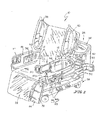
- Fig. 6 is a sectional view taken along line 6-6 of Fig. 5 showing a slide-assembly lock in the locked position;
- Fig. 7 is a view similar to Fig. 6 with the slide-assembly lock in the freed position;
- Fig. 8 is a sectional view taken along line 8-8 of Fig. 5 showing a handle lock in a locked position
- Fig. 9 is a view similar to Fig. 8 with the handle lock in the freed position;
- Fig. 10 is an enlarged partial perspective view of another embodiment of a left foot siderail with another embodiment of a slide mechanism in a retracted position and another embodiment of a handle in a first position;
- Fig. 11 is a view similar to Fig. 10 with the egress handle in a second position;
- Fig. 12 is a view similar to Fig. 11 with the slide assembly in an extended position and the egress handle in a second position.
- a patient support apparatus such as a hospital bed 10 is shown, for example, in Figs. 1 and 2 .
- the hospital bed 10 is movable between a bed position, as shown in Fig. 1 , and a chair-egress position as shown in Fig. 2 .
- the hospital bed 10 when in the bed position, provides support to a patient (not shown) such that the patient's feet are supported spaced-apart from the ground 99.
- the hospital bed 10 when in the chair-egress position, provides support to a patient such that the patient sits upright and the patient's feet are positioned on the ground 99.
- the chair-egress position is also used by patients and caregivers to help patients egress or exit the hospital bed 10.
- An egress unit 14 included in the foot siderail assemblies 16, 18 includes a slide assembly 76 that is movable between a retracted position, shown in Fig. 3 , and an extended position, shown in Figs. 1 , 2 , 4, and 5 , and a egress handle 74 that movable between a first position, shown in Fig. 3 , and a second position shown in Figs. 1 , 2 , 4, and 5 .
- a patient may support a portion of his or her weight on the egress units during egress from the hospital bed 10.
- the hospital bed 10 includes a frame 20 and a mattress 22 that is supported by the frame 20 as shown in Figs. 1 and 2 .
- the hospital bed 10 has a head end 24 and a foot end 26.
- the frame 20 includes a base 28 and an upper frame 30 coupled to the base 28 by an elevation system 32.
- the elevation system 32 is operable to raise, lower, and tilt the upper frame 30 relative to the base 28.
- the hospital bed 10 further includes a foot panel 34 positioned adjacent the foot end 26 and a head panel 36 positioned adjacent the head end 24. The foot panel 34 is removable and is removed prior to moving the hospital bed 10 into the chair-egress position shown in Fig. 2 .
- the mattress 22 of hospital bed 10 includes a top surface 60, a bottom surface (not shown), and a perimeter surface 62 as shown in Figs. 1 and 2 .
- the upper frame 30 of the frame 20 supports deck 64 with the mattress 22 supported on the deck 64.
- the deck 64 as shown in Fig. 1 , includes a head section 66, a seat section 68, a thigh section 70, and a foot section 72,
- the head section 66 pivotably raises and lowers relative to the thigh section 70.
- the thigh section 70 pivotably raises and lowers relative to the seat section 68.
- the foot section 72 is extendable and retractable to change an overall length of the foot section 72, and therefore, to change an overall length of the deck 64.
- the seat section 68 also moves, such as by translating on the upper frame 30, as the hospital bed 10 moves between the bed position and the chair-egress position.
- the thigh and foot sections 70, 72 also translate along with the seat section 68.
- the foot section 72 lowers relative to the thigh section 70 and shortens in length.
- the foot section 72 raises relative to the thigh section 70 and increases in length.
- the head section 66 extends generally vertically upwardly from the upper frame 30 and the foot section 72 extends generally downwardly from the thigh section 70 as shown in Fig. 2 .
- the hospital bed 10 also includes four siderail assemblies coupled to the upper frame 30: a patient-right head siderail assembly 38, the patient-right foot siderail assembly 18, a patient-left head siderail assembly 40, and a patient-left foot siderail assembly 16.
- Each of the siderail assemblies 16, 18, 38, and 40 is movable between a raised position, as the left foot siderail assembly 16 is shown in Fig. 1 , and a lowered position, as the right foot siderail assembly 18 is shown in Fig. 1 .
- Siderail assemblies 16, 18, 38, and 40 are sometimes referred to as siderails 16,18, 38, 40 herein.
- the left foot siderail 16 is similar to the right foot siderail 18, and thus, the following discussion of the left foot siderail 16 is equally applicable to the right foot siderail 18.
- the left foot siderail 16 includes a barrier panel 42 and a linkage 43 that includes a support assembly 44 and a guide assembly 46.
- the guide assembly 46 is coupled to the upper frame 30 in a fixed position and is configured to guide the support assembly 44 and the barrier panel 42 during movement of the foot siderail 16 between the raised and the lowered positions.
- the support assembly 44 interconnects the barrier panel 42 and the guide assembly 46 to cause the barrier panel 42 to remain in a substantially vertical orientation during movement between the raised and the lowered positions.
- the barrier panel 42 includes an outward side 48 and an oppositely facing inward side 50. As shown in Figs. 1 and 2 , inward side 50 faces toward the mattress 22 and the outward side 48 faces away from the mattress 22.
- a first user interface 54 is coupled to the outward side 48 of the barrier panel 42 for use by a caregiver (not shown). As shown in Fig. 2 , a second user interface 56 is coupled to the inward side 50 for use by a patient (not shown). Both the first and second user interfaces 54, 56 are coupled electrically to a bed controller 58 included in the hospital bed 10. The user interfaces 54, 56 allow caregivers and patients to control movement of the elevation system 32 as well as other features of the hospital bed 10.
- the barrier panel 42 further includes a first portion 51, a second portion 52, and a third portion 53 with the second portion 52 positioned between the first and the third portions 51, 53 as shown in Figs. 1-5 .
- first portion 51 is also called bottom portion 51
- second portion 52 is also called medial portion 52
- third portion 53 is also called top portion 53.
- the bottom portion 51 is coupled to the support assembly 44 and extends upwardly.
- the medial portion 52 is appended to the bottom portion 51 and extends upwardly away from the bottom portion 51.
- the top portion 53 is appended to the medial portion 52 and is arranged to extend upwardly.
- the left foot siderail 16 further includes an egress unit 14 as shown in Figs. 1-5 .
- the egress unit 14 includes a handle 74, a slide assembly 76, and an egress position controller 78 as shown in Figs. 3-5 .
- the slide assembly 76 interconnects the handle 74 to the barrier panel 42 for selective sliding movement of the handle 74 relative to the barrier panel 42.
- a caregiver uses the egress position controller 78 to retain the slide assembly 76 in the retracted position of Fig. 3 , the extended position of Figs. 4 and 5 , or any of a number of positions therebetween, and the egress handle 74 in the first position of Figs. 3 and 4 , the second position of Fig. 5 , or any of a number of positions therebetween.
- the egress position controller 78 includes a handle lock 80 and a slide lock 85.
- the handle lock 80 is used to block movement of the handle 74 relative to the slide assembly 76.
- the slide lock 85 is used to block movement of the handle 74 relative to the barrier panel 42.
- a caregiver To re-arrange the egress unit 14, a caregiver first moves the slide lock 85 from the locked position in which movement of the slide assembly 76 is blocked to the unlocked position in which the slide assembly 76 is permitted to move from a retracted position in which the handle 74 is adjacent the barrier panel 42 to an extended position in which the handle 74 is spaced-apart from the barrier panel 42 as shown in Fig. 4 . After the slide assembly 76 is in the extended position, the caregiver re-engages the slide lock 85.
- the caregiver moves the handle lock 80 from a locked position in which rotation of the handle 74 is blocked to the unlocked position in which the handle 74 is permitted to rotate relative to the slide assembly 76 from a first position generally aligned with the slide assembly 74 to a second position extending away from and perpendicular to the inward side 50 of the barrier panel 42 as suggested in Fig. 5 .
- the caregiver re-engages the handle lock 80 so that unintended movement of the handle 74 is blocked.
- the slide assembly 76 begins in the retracted position and the handle 74 begins in the first positions.
- the slide assembly 76 when in the retracted position, causes the handle 74 to lie in confronting relation to the top portion 53 of the barrier panel 42.
- the handle also lies between a head edge 23 and an oppositely spaced-apart foot edge 25 of the barrier panel 42.
- the handle 74 lies in generally coplanar relation with the barrier panel 42 and does not interfere with the movement of the siderail 16 between the raised and the lowered positions.
- the slide assembly 76 may be in retracted position when the hospital bed 10 is in either the bed position or the chair-egress position.
- the slide assembly 76 moves from the retracted position to the extended position by translating the handle 74 away from the barrier panel 42 in a longitudinal direction 90 so that the handle 74 is spared-apart from the barrier panel 42 as shown in Fig. 4 .
- the slide assembly 76 supports the handle 74 and between the extended and retracted positions.
- the extended position of the slide assembly 76 may be any of a number of intermediary positions that the handle 74 is in while the slide assembly 76 moves away from the retracted position of Fig. 3 .
- the extended position of the slide assembly 76 also minimizes a gap 94 formed between the foot panel 34 and the foot end 26 of the barrier panel 42 as suggested in Fig. 1 .
- the handle 74 is movable between the first position and the second position as shown in Figs. 4 and 5 .
- the handle 74 In the first position of Fig. 3 , the handle 74 extends in the longitudinal direction 90 toward the foot end 26 of the hospital bed 10.
- the handle 74 also lies between a middle section 532 included in the top portion 53 of the barrier panel 42 and the foot edge 25 of the barrier panel 42,
- the handle 74 cantilevers over a foot section 521 of the medial portion 52 and lies between a first plane defined by the outward side 48 and a second plane defined by the inward side 50.
- the handle 74 When the slide assembly 76 is in the extended position and the handle 74 is in the first position, the handle 74 extends away from the slide assembly 76 toward the foot end 26 and remains between the first and second planes.
- the handle 74 may be moved from the first position to the second position when the slide assembly 76 is either in the retracted position or the extended position.
- the handle 74 moves from the first position to the second position by rotating about a handle-pivot axis 86 in a counter-clockwise direction 88 about 90 degrees as suggested in Fig. 4 and shown in Fig. 5 .
- Both handles 74 of left and right foot siderails 16, 18 extend toward one another to cause a distance between the siderails 16, 18 to be minimized so that a patient is able to grip comfortably the handles 74 and support a portion of the patient's weight during egress from the hospital bed 10.
- the handle 74 extends away from the inward side 50 of the barrier panel 42.
- the handle 74, the slide assembly 76, and the barrier panel 42 cooperate together to define various widths and lengths of the siderail 16.
- the handle 74 cooperates with the barrier panel 42 to define a first barrier width 81 and a first barrier length 91 as shown in Fig. 3 .
- the handle 74 cooperates with the barrier panel 42 to define a second barrier width 82 and a second barrier length 92 as shown in Fig. 4 .
- the second barrier width 82 is about equal to the first barrier width 81.
- the second barrier length 92 is greater than the first barrier length 91.
- the handle 74 when the slide assembly 76 is in the extended position and the handle 74 is in the second position, the handle 74 cooperates with the barrier panel 42 to define a third barrier width 83 and a third barrier length 93 as shown in Fig. 5 .
- the third barrier width is greater than the first and second barrier widths 81, 82.
- the third barrier length 93 is less than the second barrier length 92, but greater than the first barrier length 91.
- the handle 74 as shown in Fig. 3 , includes a first side 111, an oppositely facing second side 112, a handle mounts 96, a forward grip 98, a first lateral grip 101, and a second lateral grip 102.
- the handle mount 96 interconnects the forward grip 98 and the lateral grips 101, 102 to the slide assembly 76 as shown in Fig. 3 .
- the first lateral grip 101 is coupled to a first end of the handle mount 96 and is arranged to extend away from the handle mount 96.
- the second lateral grip 102 is spaced-apart above and parallel to the first lateral grip 101 and coupled to the handle mount 96 to extend away the handle mount 96.
- the forward grip 98 is coupled to the first and second lateral grips 101, 102 and arranged to extend therebetween, spaced-apart from, and parallel to the handle mount 96 as shown in Fig. 3 .
- the handle mount 96, the forward grip 98, and the lateral grips 101, 102 cooperate to define a hand aperture 104 that is configured to receive a patient's hand therein during use of the handle 74.
- the first side 111 of the handle 74 is arranged to lie in generally aligned with the outward side 48 of the barrier panel 42 and the second side 112 of the handle 74 is generally aligned with the inward side 50 of the barrier panel 42.
- the handle mount 96 is arranged to lie in confronting relation with a foot surface 106 of the middle section 532 included in the top portion 53 of the barrier panel 42.
- the foot surface 106 extends upwardly away from a top surface 108 of a foot section 521 included in the medial portion 52. As shown in Figs.
- the top surface 108 and the foot surface 106 intersect one another at about a right angle and cooperate to define a handle-storage space 110 in which the handle 74 lies in when the slide assembly 76 is in the retraced position and the handle 74 is in the first position.
- the first and second sides 111, 112 of the handle 74 are generally perpendicular to the outward and inward sides 48, 50 of the barrier panel 42.
- the handle mount 96 is spaced-apart from the foot surface 106 and remains extending upwardly relative to the top surface 108.
- the two lateral grips 101, 102 extend away from the handle mount 96 in a lateral direction 9.
- the lateral direction 100 is generally perpendicular to the longitudinal direction 90.
- the forward grip 98 is cantilevered above the mattress 22 and ground 99 as shown in Fig. 2 .
- the handle 74 and the foot edge 25 of the barrier panel 42 cooperate to define a distance 180.
- the distance 180 is sufficiently large enough to permit a patient to stand up from the hospital bed 10 and have their legs positioned between the handle 74 and the top surface 60 of the mattress 22 as suggested in Fig. 2 .
- the handle mount 96 includes a first pivot joint 113, a second pivot joint 114, and a handle bar 116, and a mount housing 118 as shown in Fig. 5 .
- the mount housing 118 is coupled to the slide assembly 76 to move therewith.
- the first pivot joint 113 interconnects the top ends of the handle bar 116 and the mount housing 118.
- the second pivot joint 114 interconnects the bottom ends of the handle bar 116 and the mount housing 118.
- the handle bar 116 is configured to move about the handle-pivot axis 86 relative to the mount housing 118.
- the first and second pivot joints 113, 114 define the handle-pivot axis 86 which is generally vertical and perpendicular to a longitudinal axis of the hospital bed 10.
- the slide assembly 76 is configured to support the handle 74 for sliding movement back and forth relative to the barrier panel 42.
- the slide assembly 76 includes first and second slide-tube receivers 121,122 and first and second slide tubes 123 , 124 as shown in Figs. 4 and 5 .
- the slide-tube receivers 121, 122 are coupled to the barrier panel 42 to move therewith.
- the slide tubes 123, 124 are coupled to the slide-tube receivers for sliding movement back and forth in the longitudinal direction 90.
- the first slide-tube receiver 121 lies adjacent to a top side 126 of the top portion 53 of the barrier panel,
- the second slide-tube receiver 122 is spaced-apart below the first slide-tube receiver 121,
- the slide-tube receivers 121, 122 include a space formed in the barrier panel 42 and a bearing aperture formed in the foot surface 106.
- the bearing aperture opens into the space and supports the slide tubes 123, 124 for sliding movement.
- the slide tubes 123 , 124 are tubes having sufficient strength to support a portion of a patient's weight when the slide assemblies 74 are in the extended position and the patient is using the handles 74 to egress from the hospital bed 10.
- the handle 74 also includes the egress position controller 78 that is used to control movement of the handle 74 and the slide assembly 76. As shown diagrammatically in Figs. 3-5 , the egress position controller 78 includes the handle lock 80 and the slide lock 85. The slide lock 85 is used to block movement of the handle 74 relative to the barrier panel 42.
- the slide lock 85 is movable between the locked position shown in Fig. 6 in which the second slide tube 124 is blocked from moving relative to the second slide-tube receiver 122 and the unlocked position shown in Fig. 7 in which the slide tubes 123, 124 are permitted to slide relative to the slide-tube receivers 121, 122.
- the slide lock 85 includes a piston 128, a notch 130, a bias spring 132, and a slide-lock actuator 134.
- the notch 130 is formed in the slide tube 123 and configured to mate selectively with the piston 128 therein.
- the bias spring 132 lies between and interconnects the piston 128 and the barrier panel 42 to provide a piston-bias force 136 that urges the piston 128 to mate with the notch 130.
- the slide-lock actuator 134 is coupled to the piston 128 and is configured to transfer an actuation force 138 to the piston 128 to overcome the piston-bias force 136 and move the piston 128 away from the notch 130.
- the slide lock 95 is in the locked position in which the piston-bias force 136 has urged the piston 128 into mating contact with the notch 130.
- a caregiver uses the slide-lock actuator 134 to apply the actuation force 138 to the piston 128.
- the caregiver 140 engages the slide-lock actuator 134 to apply the actuation force 138 in the downward direction to overcome the piston-bias force 136 and move the piston 128 out of mating contact with the notch 130 so that the slide lock 85 assumes the unlocked position.
- the caregiver slides the handle 74 away from the barrier panel 42 as shown in Figs,3 and 4 to cause the slide assembly 76 to assume the extended position.
- the handle lock 80 is next moved from the locked position shown in Fig. 8 to the freed position shown in Fig. 9 .
- the handle lock 80 blocks movement of the handle 74 relative to the slide assembly 76 when the handle lock 80 is in the locked position.
- the handle 74 is free to pivot about the handle-pivot axis 86 when the handle lock 80 is in the freed position.
- the caregiver 140 applies an actuation force 143 to the handle lock 80 to move the handle lock 80 from the locked position to the freed position as shown in Fig. 8 and shown in Fig. 9 .
- the handle lock 80 includes a plunger 142, a receiver 144, and a handle-lock actuator 146 as shown in Figs. 8 and 9 .
- the plunger 142 lies in a space 178 formed in the mount housing 118 and mates with the receiver 144 when the handle lock 80 is in the locked position and is spaced-apart from the receiver 144 when the handle lock 80 is in the freed position.
- receiver 144 includes two slots 148 and 150 formed in the first pivot joint 113 of the handle 74.
- the first slot 148 is at about the two o'clock position and is associated with the handle 74 being in the second position.
- the second slot 150 is at about the five o'clock position and is associated with the handle 74 being in the first position.
- the handle-lock actuator 146 is coupled to an outer side 152 of the mount housing 118 and moves back-and-forth relative to the mount housing 118 to engage and move the plunger 142.
- the handle-lock actuator 146 of handle lock 80 includes an actuator button 154 and a bias spring 156.
- the actuator button 154 extends through an aperture 158 formed in the mount housing 118 that opens into the space 178.
- the bias spring 156 is coupled to the mount housing 118 and to the plunger 142.
- the bias spring 156 provides a plunger-bias force 160 that urges the plunger 142 to mate with the receiver 144.
- a caregiver uses the actuator button 154 to apply the actuation force 143 to the plunger 142 to overcome the plunger-bias force 160 and urge the plunger 142 away from the receiver 144.
- handle 74 may move between the first position and the second position, After the caregiver removes the actuation force 143, the plunger 142 mates with the receiver 144 when the handle 74 moves to either the first position or the second position.
- the handle lock may be a Porter Group, LLC. MECHLOK® brand locking mechanism.
- the locking mechanism may be either actuated by a caregiver applying a manual actuation force or the actuation force may be provided by a powered actuator included in the hospital bed 10.
- the powered actuator may be coupled to the bed controller and configured to respond to commands sent by the bed controller.
- a user may disengage the handle lock to free the handles 74 to move to the second position by using one of the user interfaces 54, 56 to send an input to the controller to cause the powered actuator to provide the actuation force to the locking mechanism.
- the handle 74 further includes a position sensor 162.
- the position sensor 162 is coupled electronically to the bed controller 58 also included in the hospital bed 10.
- the position sensor 162 senses the position of the plunger 142 relative to the barrier panel 42.
- the position of the handle 74 is determined as a. result of slots 148,150 having different depths. For example, the first slot 148 is deeper than the second slot 150.
- the position sensor 162 is able to sense when the handle 74 is in the first position or the second position and when the handle lock 80 is in the locked position or the unlocked position.
- the slide assembly 76 may include a slide position sensor that is also coupled to the bed controller 58.
- the slide position sensor senses the position of piston 128 of the slide lock 85.
- the position of the piston 128 may be determined as a result of the first notch 130 having a greater depth than another spaced-apart notch that is associated with the handle 74 being in the extended position, As a result, the slide position sensor is able to sense when the slide assembly is in the retracted position or the extended, position and when the slide lock 85 is in the locked position or the unlocked position.
- the position sensor 162 of the handle 74 is coupled to the bed controller 58 to communicate the position of the handle 74 to the bed controller 58 as shown in Figs. 8 and 9 .
- the position sensor of the slide lock 85 may also be coupled to the bed controller 58.
- the bed controller 58 is coupled electrically to the elevation system 32 to control vertical movement of the upper frame 30 relative to the base 28.
- the bed controller 58 also controls movement of the hospital bed 10 between the bed position and the chair-egress position. As a result of bed controller 58 being coupled to the position sensor, the bed controller 58 blocks movement of the elevation system 32 when the slide assembly 76 is in the extended position or the retracted position so as to minimize damage to the foot siderails 16, 18.
- left foot siderail 16 also includes the support assembly 44 that interconnects the barrier panel 42 to the guide assembly 46.
- the support assembly 44 embodied as a link mechanism, includes a first upper link 171, a second upper link 173, and a. lower link 172 as shown in Figs. 3-5 .
- the links 171, 172, and 173 interconnect the bottom portion 51 of the barrier panel 42 to the guide assembly 46 to cause the barrier panes 42 to pivot between the raised and lowered positions.
- the first and second upper links 171, 173 are coupled to the barrier panel 42 to cause the barrier panel 42 to pivot about a first generally horizontal pivot axis 164.
- the lower link 172 interconnects the barrier panel 42 and the guide assembly 46 to cause the barrier panel 42 to pivot about a second generally horizontal pivot axis 166.
- first pivot axis 164 is spaced-apart above and parallel to the second pivot axis 166.
- the first and second pivot axes 164, 166 lie generally in parallel relation to a longitudinal axis of the hospital bed it that extends between the head end 24 and the foot end 26 of the frame 20.
- the support assembly 44 further includes a pair of barrier extenders 168,170 as shown in Figs. 1-5 .
- the first barrier extender 168 is coupled to the barrier panel 42 to pivot about the first pivot axis 164 and is coupled to the first upper link 171 to move therewith.
- the second barrier extender 170 is coupled to the barrier panel 42 to pivot about the first pivot axis 164 and is coupled to the second upper link 173 to move therewith.
- the barrier extenders 168 and 170 cooperate with the outward side 48 of barrier panel 42 to establish an enlarged barrier surface having a raised height 174 when the foot siderail 16 is in the raised position as shown in Fig. 3 .
- first and second pivot joints 113, 114 cooperate to define the handle-pivot axis 86 and the handle-pivot axis 86 is spaced-apart above and parallel to the first pivot axis 164
- the left foot siderail 16 also illustratively includes at least one latching mechanism 176, as shown in Figs. 1 and 2 .
- the latching mechanism 176 releasably secures a portion of the foot siderail assembly 16, 18 to the frame 20 of the patient support apparatus.
- the latching mechanism 176 may releasably secure the barrier panel 42 in one or more positions.
- the latching mechanism 176 secures the barrier panel 42 in the raised position to block movement of the barrier panel 42 from the raised position to the lowered position.
- the latching mechanism may releasably secure a barrier panel with a support assembly, releasably secure the support assembly with the frame of the patient support apparatus, and releasably secure the support assembly with the guide assembly.
- FIG. 10-12 Another embodiment of a left foot siderail assembly 216 is shown in Figs. 10-12 .
- the left foot siderail assembly 16 is omitted from the hospital bed 210 and replaced with the left foot siderail 216.
- Left foot siderail 216 includes an egress unit 214 and a barrier panel 242.
- the egress unit 214 like the egress unit 14, is coupled the barrier panel 242 and configured to move as shown in Figs. 1 and 12 .
- the egress unit 214 includes a slide assembly 276 movable between a retracted position and an extended position and an egress handle 274 that is movable between a first position and a second position.
- the egress unit When the slide assembly 276 is in the extended position and the handle 274 is in the second position, the egress unit supports a portion of a patient's weight thereon during egress of the patient from the hospital bed 210 when the hospital bed 210 is in the chair-egress position.
- the barrier panel 242 includes a first portion 251, a second portion 252, and a third portion 253.
- the first portion 251 is also called a bottom portion 251
- the second portion 252 is also called a medial portion 252
- the third portion 253 is also called a top portion 253.
- the top portion 253 is appended to the medial portion 252 to extend upwardly away from the medial portion 252.
- the barrier panel 242 also includes an outward side 248 that faces away from the mattress 22, an oppositely facing inward side 250 that faces toward the mattress 22, a foot edge 225 that faces toward the foot end 26 of the hospital bed 210, and a head edge 223 that faces toward the head end 24.
- the egress unit 214 includes a handle 274 and a slide assembly 276 as shown in Figs. 10-12 .
- the slide assembly 276 interconnects the handle 274 to the barrier panel 242 for selective sliding movement of the handle 274 relative to the barrier panel 242.
- the egress unit 214 may also include an egress position controller that is used by a caregiver to retain the handle 274 in the first position of Fig. 10 , the second position of Figs. 11 and 12 , or any position therebetween.
- a caregiver may disengage an egress position controller and then move the handle 274 from the first position of Fig. 10 to the second position of Fig. 11 and move the slide assembly 276 from the retraced position of Figs. 10 and 11 to the extended position of Fig. 12 .
- the egress-egress position controller may include a handle lock and a slide-assembly lock.
- the caregiver first moves the handle 274 about a handle-pivot axis 286 in a counter-clockwise direction 288 from a first position to a second position in which the handle 274 extends away from the inward side 250 of the barrier panel 242 toward the mattress 22 as shown in Fig. 11 .
- the caregiver slides the handle 274 away from the barrier panel 242 toward the foot end 26 of the hospital bed 210 to cause the slide assembly 276 to assume the extended position as shown in Fig. 12 ,
- the slide assembly 276 may be in the retracted position when the hospital bed 210 is in bed position or the chair-egress position.
- the handle 274 is movable about the handle - pivot axis 286 between the first position and the second position whether the slide assembly 276 is in the retracted position or the extended position.
- the handle 274 when in the first position, extends downwardly toward the ground 99 and lies in a recess 206 that is formed in the outward side 248 of the barrier panel 242.
- the handle 274 cooperates with the barrier panel 242 to define a first barrier width 281 and a first barrier length 291 as shown in Fig. 10 .
- the handle 274 moves from the first position to the second position by rotating about the handle-pivot axis 286 in the counter-clockwise direction 288 about 270 degrees as shown in Fig. 12 .
- Both handles of left and right siderails 16, 18 extend toward one another to minimize a distance between the foot siderails 16, 18.
- the minimized distance between the foot siderails allows a patient to grip the handles 274 to support a portion of the patient's weight during from the hospital bed 210,
- the handle 274 cooperates with the barrier panel 242 to define a second barrier width 282 and a second barrier length 292.
- the second barrier width 282 is relatively larger than the first barrier width and the second barrier length 292 is about equal to the first barrier length 291.
- the slide assembly 276 finally moves from the retracted position to the extended position by translating the handle 274 away from the barrier panel 242 as shown in Fig. 12 .
- the slide assembly 276 is configured to support the handle 274 as it slides along the handle-pivot axis 286 between the extended and retracted positions.
- the extended position of the slide assembly 276 may be an intermediary position of the handle 274.
- the extended position of the slide assembly 276 also provides means for extending a length of the barrier panel to minimize a gap 94 formed between the foot panel 34 and the foot edge 225 of the barrier panel 242.
- the handle 274 When the handle 274 is in the second position, and the slide assembly 276 is in the extended position, the handle 274 cooperates with the barrier panel 242 to define a third barrier width 283 and a third barrier length 293.
- the third barrier width 283 is about equal to the second barrier width 282 and the third barrier length 293 is greater than the first and second barrier lengths 291, 292.
- the handle 274 includes a first side 211, an oppositely facing second side 212, a handle mount 296, a forward grip 298, and a lateral grip 200.
- the handle mount 296 interconnects the forward grip 298 and the lateral grip 200 to the slide assembly 276 as shown in Fig. 12 .
- the lateral grip 200 is coupled to the handle mount 296 and extends away from the handle mount 296 at an angle to interconnect to the forward grip 298 to the handle mount 296.
- the forward grip 298 is coupled to the lateral grip 200 and is arranged to extend to the handle mount 296 as shown in Fig. 10 .
- the handle mount 296, the forward grip 298, and the lateral grip 200 cooperate together to define a first aperture 208 that is configured to receive a patient's hand therein during use of the handle 274.
- a second aperture 209 is formed by the handle mount 296, a top side 218 included in a foot section 2521 of the medial portion 252, and a foot surface 220 included in a middle section 2532 included in the top portion 253 when the slide assembly 276 is in the retracted position and the handle 274 is in the first position.
- the first and second sides 211, 212 of the handle 274 lie perpendicular to the outward and inward sides 248, 250 of the barrier panel 242 when the handle 274 isin the second position.
- the lateral grip 200 extends away from the handle mount 296 in the lateral direction 90.
- the forward grip 298 is cantilevered above the mattress 22 as suggested in Fig. 12 .
- the handle mount 296 of the handle 274 includes a first end near the foot end 26 of the hospital bed 210 and an opposite second end near the head end 24 as suggested in Figs. 10-12 .
- the first end is coupled to the forward grip 298 and the second end is coupled to the lateral grip 200 to cause the handle mount 296 to extend therebetween.
- the second end of the handle mount 296 is also coupled to the slide assembly 276.
- the handle mount 296 defines the handle-pivot axis 286 which is generally horizontal and parallel to the longitudinal axis of the hospital bed 210.
- the slide assembly 276 is configured to support the handle 274 for sliding movement back and forth relative to the barrier panel 242.
- the slide-tube receiver 222 is coupled to the top portion 253 of the barrier panel 242 to move therewith.
- the slide tube 228 is coupled to the slide-tube receiver 222 for sliding movement back and forth in the longitudinal direction 90.
- the slide-tube receiver 222 lies adjacent to a top side 230 of the top portion 253 of the barrier panel 242.
- the slide-tube receiver 222 of Figs. 10 and 11 includes a space formed in the barrier panel 242 and a bearing aperture formed in a foot surface 220 includes in the middle section 2532 of the top portion 253.
- the bearing aperture opens into the space and is configured to support the slide tube 228 for sliding movement therein.
- the slide tube 228 is configured to have sufficient strength to support a portion of the patient's weight when the slide assembles 276 are in the extended positions and the patient is using the handles 274 to egress from the hospital bed 210.
- the foot siderail may further include an alert light that is coupled electrically to the bed controller 58 to provide light when called upon by the bed controller 58.
- the alert light may be coupled to the barrier panel to shine light on the egress unit.
- the bed controller may activate the alert light when the hospital bed is in the chair-egress position to alert a patient or caregiver that the handle is available for use.
- the alert light may provide a reminder to users and helps patients use the handle included in the egress unit when ambient room light is low.
- the egress unit may include a user interface that is mounted to the handle and coupled electrically to the bed controller 58.
- the bed controller 58 is coupled electrically to the elevation system 32 to control movement of the upper frame 30 relative to the base 28 in response to inputs received from any of the user interfaces,
- a patient may use the user interface to move the hospital bed 10 from the chair-egress position to the bed position.
- the patient may also cause the hospital bed 10 to move from the chair-egress position to an egress-lift position in which the deck 64 is arranged in the chair-egress position, but the elevation system 32 tilts the upper frame 30 and the deck 64 upwardly to aid the patient during egress from the hospital bed 10.
- Illustrative bed 10 is a so-called chair egress bed, in that it is movable between a bed position, as shown in Fig. 1 , and a chair-egress position as shown in Fig. 2 .
- the teachings of this disclosure are applicable to all types of hospital beds, including those that are incapable of achieving a chair-egress position. Some hospital beds are only able to move into a chair-like position, sometimes referred to by those in the art as a "cardiac chair position," and this disclosure is equally applicable to those types of beds.
- the teachings of this disclosure are applicable to other types of patient support apparatuses such as stretchers, motorized chairs, operating room (OR) tables, specialty surgical tables such as orthopedic surgery tables, examination tables, and the like.
Abstract
Description
- The present disclosure is related to a support apparatus for supporting a patient. More particularly, the present disclosure relates to a bed that can be manipulated to achieve both a conventional bed position having a horizontal support surface and a chair position having the feet of the patient on or adjacent to the floor and the head and back of the patient supported above a seat formed by the bed,
- It is known to provide beds that have a head siderail assembly coupled to a head portion of the support surface and a foot siderail assembly coupled to a seat portion of the support surface. The siderail assemblies may be movable independently of one another between a raised position and a lowered position. The siderail assemblies may be used in the raised position to retain patients resting on the support surface and in the lowered position to transfer patients from the bed to another support apparatus, allow a caregiver improved access to the patient, or to help with entering and exiting the bed ...
- It is also known that patients egress from a side of the bed. Before the patient is able to egress, the patient must rotate the patient's body on the support surface to face toward the side, swing the patient's legs over the side of the bed, and remain sitting in an upright position without support from the support surface to the patient's back. Such coordinated movement to egress from the side of the bed may be difficult for some patients. As a result, egress from the chair position of the bed may be more suitable to some patients. With the bed in the chair position, the patient begins with the patient's feet resting on the floor, the patient sitting in the upright position, and the patient's back being supported by the support surface. To egress from the bed, the patient supports a portion of the patient's weight on the support surface on each side of the patient or on a caregiver standing next to the bed. The patient then leans forward and transfers the remaining weight to the patient's feet.
- The present application discloses one or more of the features recited in the appended claims and/or the following features which, alone or in any combination.
- According to one aspect of the present disclosure, a siderail assembly for a patient support apparatus includes a guide, a support, a barrier, and an egress unit. The guide mounts to a frame of the patient support apparatus and the support is coupled to the guide to move relative to the guide. The barrier is coupled to the support to pivot about a generally horizontal axis between a raised position and a lowered position. The barrier includes an outward side that faces away from a patient support apparatus and an inward side that faces toward a deck included in a patient support apparatus. The egress unit is coupled to the barrier to move relative to the barrier between a barrier position and an egress position. When the egress unit is in the barrier position, the egress unit lies in a generally vertical plane adjacent to the barrier. When the egress unit is in the egress position, the egress unit is spaced-apart from barrier and a portion of the egress unit extends away from the inward side of the barrier.
- In some embodiments, the egress unit includes a handle and a slide assembly. The slide assembly may be arranged to lie between and to interconnect the handle to the barrier. The slide assembly may be movable between a retracted position in which the handle is adjacent the barrier and an extended position in which the handle has slid away from the barrier in a longitudinal direction.
- The handle and the barrier may cooperate to define a first barrier length when the slide assembly is in the retracted position. The handle and the barrier may cooperate to define a second barrier length when the slide assembly is in the extended position. The first barrier length may be less than the second barrier length.
- In some embodiments, the handle is coupled to the slide assembly to move about a pivot axis between a first position and a second position. When the handle is in the first position, the handle may extend away from the slide assembly in a longitudinal direction and lie in a generally vertical first plane. When the handle is in the second position, the handle may extend away from the slide assembly in a lateral direction and lie in a generally vertical second plane. The pivot axis may intersect the generally horizontal axis at about a right angle. The lateral direction may be orthogonal to the longitudinal direction and the second plane may be orthogonal to the first plane.
- The egress unit may further comprise an egress position controller. The egress position controller may be configured to selectively block movement of the egress unit between the barrier position and the egress position. In some embodiments, the egress position controller includes a handle lock and a slide lock. The handle lock may be coupled to the to the slide assembly to move therewith and may be configured to selectively block movement of the handle relative to the slide assembly. The slide lock may be coupled to the barrier to selectively block movement of the handle relative to the barrier.
- The handle lock may include a plunger, a receiver, and a bias spring. The plunger may be coupled to the slide assembly to move relative to the slide assembly. The receiver may be formed in the handle and may be configured to mate with the plunger when the handle lock is in a locked position. The bias spring may interconnect the plunger and the slide assembly and may be configured to provide a bias force to the plunger to urge the plunger to mate with the receiver.
- In some embodiments, the slide lock includes a piston, a notch, and a bias spring. The piston may be coupled to the barrier to move relative to the barrier. The notch may be formed in the slide assembly and may be configured to mate with the plunger when the slide lock is in a locked position. The bias spring may interconnect the piston and the barrier and may be configured to provide a bias force to the piston to urge the piston to mate with the notch,
- In some embodiments, the handle is coupled to the slide assembly to move about a pivot axis between a first position and a second position. When the handle is in the first position, the handle may lie in a recess formed in the barrier. When the handle is in the second position, the handle may extend away from the inner side of the barrier and may lies in a generally horizontal plane. The horizontally plane may be generally orthogonal to both the inner and outer sides of the barrier. In some embodiments, the pivot axis may be spaced-apart above and generally parallel to generally horizontal axis.
- In another aspect of the present disclosure, a siderail assembly for a patient support apparatus includes a linkage, a barrier, and an egress unit. The linkage mounts to a side of a patient support apparatus and the side extends between a foot end and a head end of the patient support apparatus. The barrier is movable between a raised position and lowered position, The barrier includes a foot edge arranged to face the foot end and a spaced-apart head edge arranged to face toward the head end. The barrier also includes an inner side, an outer side, a first portion, a second portion, and a third portion. The inner side faces toward a mattress included in the patient support apparatus and the outer side faces away from the mattress. The fist portion is coupled to the linkage and is arranged to extend between the head and the foot edges, The second portion is appended to the first portion, extends between the head and foot edges, and extends in an upward direction. The third portion is appended to the second portion and may extend in the upward direction away from the second portion. The egress unit includes a handle and a slide assembly that is arranged to lie between the barrier and the handle. The slide assembly interconnects the handle to the barrier and is movable between a retracted position and an extended position. When the slide assembly is in the retracted position, the handle lies in confronting relation with the barrier. When the slide assembly is in the extended position, the handle lies in spaced-apart relation to the barrier. The handle is movable between a first position in which the handle extends away from the barrier toward the foot end of the patient support apparatus and a second position in which the handle extends away from inner side of the barrier toward the mattress.
- In some embodiments, the slide assembly is spaced-apart above the first portion of the barrier and is coupled to the third portion. The slide assembly may include a first tube and a first slide-tube receiver. The first slide-tube receiver may be coupled to the top portion of the barrier to move with the barrier. The first slide tube may be coupled to the first slide-tube receiver for translating movement back and forth relative to the slide-tube receiver. The first slide tube may be generally aligned with the pivot axis to move back and forth along the pivot axis.
- The slide assembly may further include a second slide-tube and a second slide-tube receiver. The second slide tube may be spaced-apart below the first slide tube. The second slide-tube receiver may be coupled to the second portion of the barrier to move therewith and may be spaced-apart below the first slide-tube receiver,
- In another aspect of the present disclosure, a siderail assembly for a patient support apparatus includes a guide, a support, a barrier, and an egress unit. The guide mounts to a frame included in a patient support apparatus. The support is coupled to the guide to move relative to the guide. The barrier is coupled to the support to move between a raised position and a lowered position while the barrier remains in a substantially vertical orientation. The barrier includes a foot edge, a head edge, an inner side, an outer side, a first portion, a second portion, and a third portion. The foot edge is arranged to face toward a foot end of the patient support apparatus. The head edge is arranged to face toward a head end of the patient support apparatus. The inner side is adapted to face toward a mattress included in the patient support apparatus and the outer side is adapted to face away from the mattress. The first portion is coupled to the linkage and is arranged to extend between the head and the foot edges. The second portion is appended to the first portion, is arranged to extend in an upward direction, and is arranged to extend between the head and foot edges. The third portion is appended to the second portion, and is arranged to extend in the upward direction away from the second portion to locate the second portion between the first and third portions. The egress unit includes a handle and a slide assembly that interconnects the handle to the barrier. The slide assembly is movable from a retracted position in which the handle is in confronting relation with the barrier to an extended position in which the handle has slid away from the barrier in the longitudinal direction toward the foot end of the patient support apparatus. The handle is movable in a counter-clockwise direction about a pivot axis from a first position in which the handle is arranged to lie in a generally vertical plane to a second position in which the handle extends away the inner side of the barrier and lies in a plane. The generally vertical plane is generally parallel to the outward and inner sides of the barrier and the plane is generally orthogonal to the inner and outer sides of the barrier.
- In some embodiments, the siderail assembly further includes a light that is coupled to the barrier. The light may be configured to provide light to the handle in response to a command from a bed controller, The siderail assembly may further comprise a sensor that is configured to sense a position of the handle relative to the barrier. The sensor may send an input to a bed controller to control movement of the patient support apparatus in response to the second input.
- The invention will now be further described by way of example with reference to the accompanying drawings, in which:
-
Fig. 1 is a perspective view of a patient support apparatus in a generally flat configuration and having three siderails in a raised position and one siderail in the lowered position; -
Fig. 2 is a perspective view of the patient support apparatus ofFig. 1 moved to a chair-egress position; -
Fig. 3 is an enlarged partial perspective view of the patient-left foot siderail ofFigs, 1 and2 with a slide assembly in a retracted position and an egress handle in a first position ; -
Fig. 4 is a view similar toFig. 3 with the slide assembly in an extended position and the handle in the first position; -
Fig. 5 is a view similar toFig. 4 with the slide assembly in the extended position and the egress handle in a second position; -
Fig. 6 is a sectional view taken along line 6-6 ofFig. 5 showing a slide-assembly lock in the locked position; -
Fig. 7 is a view similar toFig. 6 with the slide-assembly lock in the freed position; -
Fig. 8 is a sectional view taken along line 8-8 ofFig. 5 showing a handle lock in a locked position; -
Fig. 9 is a view similar toFig. 8 with the handle lock in the freed position; -
Fig. 10 is an enlarged partial perspective view of another embodiment of a left foot siderail with another embodiment of a slide mechanism in a retracted position and another embodiment of a handle in a first position; -
Fig. 11 is a view similar toFig. 10 with the egress handle in a second position; and -
Fig. 12 is a view similar toFig. 11 with the slide assembly in an extended position and the egress handle in a second position. - A patient support apparatus, such as a
hospital bed 10 is shown, for example, inFigs. 1 and2 . Thehospital bed 10 is movable between a bed position, as shown inFig. 1 , and a chair-egress position as shown inFig. 2 . Thehospital bed 10, when in the bed position, provides support to a patient (not shown) such that the patient's feet are supported spaced-apart from theground 99. Thehospital bed 10, when in the chair-egress position, provides support to a patient such that the patient sits upright and the patient's feet are positioned on theground 99. The chair-egress position is also used by patients and caregivers to help patients egress or exit thehospital bed 10. Anegress unit 14 included in thefoot siderail assemblies slide assembly 76 that is movable between a retracted position, shown inFig. 3 , and an extended position, shown inFigs. 1 ,2 ,4, and 5 , and aegress handle 74 that movable between a first position, shown inFig. 3 , and a second position shown inFigs. 1 ,2 ,4, and 5 . When thehandle 74 is in the second position and theslide assembly 76 is in the extended position, a patient may support a portion of his or her weight on the egress units during egress from thehospital bed 10. - The
hospital bed 10 includes aframe 20 and amattress 22 that is supported by theframe 20 as shown inFigs. 1 and2 . Thehospital bed 10 has ahead end 24 and afoot end 26. Theframe 20 includes abase 28 and anupper frame 30 coupled to thebase 28 by anelevation system 32. Theelevation system 32 is operable to raise, lower, and tilt theupper frame 30 relative to thebase 28. Thehospital bed 10 further includes afoot panel 34 positioned adjacent thefoot end 26 and ahead panel 36 positioned adjacent thehead end 24. Thefoot panel 34 is removable and is removed prior to moving thehospital bed 10 into the chair-egress position shown inFig. 2 . - The
mattress 22 ofhospital bed 10 includes atop surface 60, a bottom surface (not shown), and aperimeter surface 62 as shown inFigs. 1 and2 . Theupper frame 30 of theframe 20 supportsdeck 64 with themattress 22 supported on thedeck 64. Thedeck 64, as shown inFig. 1 , includes ahead section 66, a seat section 68, athigh section 70, and afoot section 72, Thehead section 66 pivotably raises and lowers relative to thethigh section 70. Additionally, thethigh section 70 pivotably raises and lowers relative to the seat section 68. Also, thefoot section 72 is extendable and retractable to change an overall length of thefoot section 72, and therefore, to change an overall length of thedeck 64. - In some embodiments, the seat section 68 also moves, such as by translating on the
upper frame 30, as thehospital bed 10 moves between the bed position and the chair-egress position. In those embodiments where the seat section 68 translates along theupper frame 30, the thigh andfoot sections hospital bed 10 moves from the bed position to the chair-egress position, thefoot section 72 lowers relative to thethigh section 70 and shortens in length. As thehospital bed 10 moves from the chair-egress position to the bed position, thefoot section 72 raises relative to thethigh section 70 and increases in length. Thus, in the chair-egress position, thehead section 66 extends generally vertically upwardly from theupper frame 30 and thefoot section 72 extends generally downwardly from thethigh section 70 as shown inFig. 2 . - The
hospital bed 10 also includes four siderail assemblies coupled to the upper frame 30: a patient-righthead siderail assembly 38, the patient-rightfoot siderail assembly 18, a patient-lefthead siderail assembly 40, and a patient-leftfoot siderail assembly 16. Each of thesiderail assemblies foot siderail assembly 16 is shown inFig. 1 , and a lowered position, as the rightfoot siderail assembly 18 is shown inFig. 1 .Siderail assemblies - The
left foot siderail 16 is similar to theright foot siderail 18, and thus, the following discussion of theleft foot siderail 16 is equally applicable to theright foot siderail 18. Theleft foot siderail 16 includes abarrier panel 42 and alinkage 43 that includes asupport assembly 44 and aguide assembly 46. Theguide assembly 46 is coupled to theupper frame 30 in a fixed position and is configured to guide thesupport assembly 44 and thebarrier panel 42 during movement of thefoot siderail 16 between the raised and the lowered positions. Thesupport assembly 44 interconnects thebarrier panel 42 and theguide assembly 46 to cause thebarrier panel 42 to remain in a substantially vertical orientation during movement between the raised and the lowered positions. - The
barrier panel 42 includes anoutward side 48 and an oppositely facinginward side 50. As shown inFigs. 1 and2 ,inward side 50 faces toward themattress 22 and theoutward side 48 faces away from themattress 22. Afirst user interface 54 is coupled to theoutward side 48 of thebarrier panel 42 for use by a caregiver (not shown). As shown inFig. 2 , asecond user interface 56 is coupled to theinward side 50 for use by a patient (not shown). Both the first andsecond user interfaces bed controller 58 included in thehospital bed 10. Theuser interfaces elevation system 32 as well as other features of thehospital bed 10. - The
barrier panel 42 further includes afirst portion 51, asecond portion 52, and athird portion 53 with thesecond portion 52 positioned between the first and thethird portions Figs. 1-5 . Illustratively,first portion 51 is also calledbottom portion 51,second portion 52 is also calledmedial portion 52, andthird portion 53 is also calledtop portion 53. Thebottom portion 51 is coupled to thesupport assembly 44 and extends upwardly. Themedial portion 52 is appended to thebottom portion 51 and extends upwardly away from thebottom portion 51. Thetop portion 53 is appended to themedial portion 52 and is arranged to extend upwardly. - The
left foot siderail 16 further includes anegress unit 14 as shown inFigs. 1-5 . Theegress unit 14 includes ahandle 74, aslide assembly 76, and anegress position controller 78 as shown inFigs. 3-5 . Theslide assembly 76 interconnects thehandle 74 to thebarrier panel 42 for selective sliding movement of thehandle 74 relative to thebarrier panel 42. A caregiver uses theegress position controller 78 to retain theslide assembly 76 in the retracted position ofFig. 3 , the extended position ofFigs. 4 and 5 , or any of a number of positions therebetween, and the egress handle 74 in the first position ofFigs. 3 and 4 , the second position ofFig. 5 , or any of a number of positions therebetween. - A caregiver uses the
handle 74 and theslide assembly 76 by disengaging theegress position controller 78 as suggested inFigs. 3-5 . Theegress position controller 78 includes ahandle lock 80 and aslide lock 85. Thehandle lock 80 is used to block movement of thehandle 74 relative to theslide assembly 76. Theslide lock 85 is used to block movement of thehandle 74 relative to thebarrier panel 42. To re-arrange theegress unit 14, a caregiver first moves theslide lock 85 from the locked position in which movement of theslide assembly 76 is blocked to the unlocked position in which theslide assembly 76 is permitted to move from a retracted position in which thehandle 74 is adjacent thebarrier panel 42 to an extended position in which thehandle 74 is spaced-apart from thebarrier panel 42 as shown inFig. 4 . After theslide assembly 76 is in the extended position, the caregiver re-engages theslide lock 85. Next, the caregiver moves thehandle lock 80 from a locked position in which rotation of thehandle 74 is blocked to the unlocked position in which thehandle 74 is permitted to rotate relative to theslide assembly 76 from a first position generally aligned with theslide assembly 74 to a second position extending away from and perpendicular to theinward side 50 of thebarrier panel 42 as suggested inFig. 5 . Finally, the caregiver re-engages thehandle lock 80 so that unintended movement of thehandle 74 is blocked. - As shown in
Fig. 3 , theslide assembly 76 begins in the retracted position and thehandle 74 begins in the first positions. Theslide assembly 76, when in the retracted position, causes thehandle 74 to lie in confronting relation to thetop portion 53 of thebarrier panel 42. As shown inFig. 3 , the handle also lies between a head edge 23 and an oppositely spaced-apartfoot edge 25 of thebarrier panel 42. Thehandle 74 lies in generally coplanar relation with thebarrier panel 42 and does not interfere with the movement of thesiderail 16 between the raised and the lowered positions. Theslide assembly 76 may be in retracted position when thehospital bed 10 is in either the bed position or the chair-egress position. - The
slide assembly 76 moves from the retracted position to the extended position by translating thehandle 74 away from thebarrier panel 42 in alongitudinal direction 90 so that thehandle 74 is spared-apart from thebarrier panel 42 as shown inFig. 4 . Theslide assembly 76 supports thehandle 74 and between the extended and retracted positions. The extended position of theslide assembly 76 may be any of a number of intermediary positions that thehandle 74 is in while theslide assembly 76 moves away from the retracted position ofFig. 3 . The extended position of theslide assembly 76 also minimizes agap 94 formed between thefoot panel 34 and thefoot end 26 of thebarrier panel 42 as suggested inFig. 1 . - The
handle 74 is movable between the first position and the second position as shown inFigs. 4 and 5 . In the first position ofFig. 3 , thehandle 74 extends in thelongitudinal direction 90 toward thefoot end 26 of thehospital bed 10. Thehandle 74 also lies between amiddle section 532 included in thetop portion 53 of thebarrier panel 42 and thefoot edge 25 of thebarrier panel 42, Thehandle 74 cantilevers over afoot section 521 of themedial portion 52 and lies between a first plane defined by theoutward side 48 and a second plane defined by theinward side 50. When theslide assembly 76 is in the extended position and thehandle 74 is in the first position, thehandle 74 extends away from theslide assembly 76 toward thefoot end 26 and remains between the first and second planes. - As discussed above, the
handle 74 may be moved from the first position to the second position when theslide assembly 76 is either in the retracted position or the extended position. Thehandle 74 moves from the first position to the second position by rotating about a handle-pivot axis 86 in acounter-clockwise direction 88 about 90 degrees as suggested inFig. 4 and shown inFig. 5 . Both handles 74 of left andright foot siderails handles 74 and support a portion of the patient's weight during egress from thehospital bed 10. Thehandle 74 extends away from theinward side 50 of thebarrier panel 42. - The
handle 74, theslide assembly 76, and thebarrier panel 42 cooperate together to define various widths and lengths of thesiderail 16. When theslide assembly 76 is in the retracted position and thehandle 74 is in the second position, thehandle 74 cooperates with thebarrier panel 42 to define afirst barrier width 81 and a first barrier length 91 as shown inFig. 3 . In another example, when theslide assembly 76 is in the extended position and thehandle 74 is in the first position, thehandle 74 cooperates with thebarrier panel 42 to define asecond barrier width 82 and asecond barrier length 92 as shown inFig. 4 . Thesecond barrier width 82 is about equal to thefirst barrier width 81. Thesecond barrier length 92 is greater than the first barrier length 91. In yet another example, when theslide assembly 76 is in the extended position and thehandle 74 is in the second position, thehandle 74 cooperates with thebarrier panel 42 to define a third barrier width 83 and athird barrier length 93 as shown inFig. 5 . The third barrier width is greater than the first andsecond barrier widths third barrier length 93 is less than thesecond barrier length 92, but greater than the first barrier length 91. - The
handle 74, as shown inFig. 3 , includes a first side 111, an oppositely facingsecond side 112, a handle mounts 96, aforward grip 98, a firstlateral grip 101, and a secondlateral grip 102. Thehandle mount 96 interconnects theforward grip 98 and the lateral grips 101, 102 to theslide assembly 76 as shown inFig. 3 . The firstlateral grip 101 is coupled to a first end of thehandle mount 96 and is arranged to extend away from thehandle mount 96. The secondlateral grip 102 is spaced-apart above and parallel to the firstlateral grip 101 and coupled to thehandle mount 96 to extend away thehandle mount 96. Theforward grip 98 is coupled to the first and second lateral grips 101, 102 and arranged to extend therebetween, spaced-apart from, and parallel to thehandle mount 96 as shown inFig. 3 . Thehandle mount 96, theforward grip 98, and the lateral grips 101, 102 cooperate to define ahand aperture 104 that is configured to receive a patient's hand therein during use of thehandle 74. - When the
handle 74 is in the first position, the first side 111 of thehandle 74 is arranged to lie in generally aligned with theoutward side 48 of thebarrier panel 42 and thesecond side 112 of thehandle 74 is generally aligned with theinward side 50 of thebarrier panel 42. Thehandle mount 96 is arranged to lie in confronting relation with afoot surface 106 of themiddle section 532 included in thetop portion 53 of thebarrier panel 42. Thefoot surface 106 extends upwardly away from atop surface 108 of afoot section 521 included in themedial portion 52. As shown inFigs. 4 and 5 , thetop surface 108 and thefoot surface 106 intersect one another at about a right angle and cooperate to define a handle-storage space 110 in which thehandle 74 lies in when theslide assembly 76 is in the retraced position and thehandle 74 is in the first position. - When the
handle 74 is in the second position, the first andsecond sides 111, 112 of thehandle 74 are generally perpendicular to the outward andinward sides barrier panel 42. Thehandle mount 96 is spaced-apart from thefoot surface 106 and remains extending upwardly relative to thetop surface 108. The twolateral grips handle mount 96 in a lateral direction 9. As shown inFig. I , thelateral direction 100 is generally perpendicular to thelongitudinal direction 90. Theforward grip 98 is cantilevered above themattress 22 andground 99 as shown inFig. 2 . When thehospital bed 10 is in the chair-egress position and theslide assembly 76 is in the extended position and thehandle 74 is in the second position, thehandle 74 and thefoot edge 25 of thebarrier panel 42 cooperate to define adistance 180. Thedistance 180 is sufficiently large enough to permit a patient to stand up from thehospital bed 10 and have their legs positioned between thehandle 74 and thetop surface 60 of themattress 22 as suggested inFig. 2 . - The
handle mount 96 includes a first pivot joint 113, a second pivot joint 114, and ahandle bar 116, and amount housing 118 as shown inFig. 5 . Themount housing 118 is coupled to theslide assembly 76 to move therewith. The first pivot joint 113 interconnects the top ends of thehandle bar 116 and themount housing 118. The second pivot joint 114 interconnects the bottom ends of thehandle bar 116 and themount housing 118. Thehandle bar 116 is configured to move about the handle-pivot axis 86 relative to themount housing 118. As shown inFig. 5 , the first and second pivot joints 113, 114 define the handle-pivot axis 86 which is generally vertical and perpendicular to a longitudinal axis of thehospital bed 10. - As discussed previously, the
slide assembly 76 is configured to support thehandle 74 for sliding movement back and forth relative to thebarrier panel 42. Theslide assembly 76 includes first and second slide-tube receivers 121,122 and first andsecond slide tubes 123, 124 as shown inFigs. 4 and 5 . The slide-tube receivers barrier panel 42 to move therewith. Theslide tubes longitudinal direction 90. The first slide-tube receiver 121 lies adjacent to atop side 126 of thetop portion 53 of the barrier panel, The second slide-tube receiver 122 is spaced-apart below the first slide-tube receiver 121, - The slide-
tube receivers Figs. 3-5 , include a space formed in thebarrier panel 42 and a bearing aperture formed in thefoot surface 106. The bearing aperture opens into the space and supports theslide tubes slide tubes 123, 124 are tubes having sufficient strength to support a portion of a patient's weight when theslide assemblies 74 are in the extended position and the patient is using thehandles 74 to egress from thehospital bed 10. - The
handle 74, as discussed previously, also includes theegress position controller 78 that is used to control movement of thehandle 74 and theslide assembly 76. As shown diagrammatically inFigs. 3-5 , theegress position controller 78 includes thehandle lock 80 and theslide lock 85. Theslide lock 85 is used to block movement of thehandle 74 relative to thebarrier panel 42. - The
slide lock 85 is movable between the locked position shown inFig. 6 in which thesecond slide tube 124 is blocked from moving relative to the second slide-tube receiver 122 and the unlocked position shown inFig. 7 in which theslide tubes tube receivers slide lock 85 includes apiston 128, anotch 130, abias spring 132, and a slide-lock actuator 134. Thenotch 130 is formed in theslide tube 123 and configured to mate selectively with thepiston 128 therein. Thebias spring 132 lies between and interconnects thepiston 128 and thebarrier panel 42 to provide a piston-bias force 136 that urges thepiston 128 to mate with thenotch 130. The slide-lock actuator 134 is coupled to thepiston 128 and is configured to transfer anactuation force 138 to thepiston 128 to overcome the piston-bias force 136 and move thepiston 128 away from thenotch 130. - As shown in
Fig. 6 , the slide lock 95 is in the locked position in which the piston-bias force 136 has urged thepiston 128 into mating contact with thenotch 130. A caregiver uses the slide-lock actuator 134 to apply theactuation force 138 to thepiston 128. As illustrated inFig. 7 , thecaregiver 140 engages the slide-lock actuator 134 to apply theactuation force 138 in the downward direction to overcome the piston-bias force 136 and move thepiston 128 out of mating contact with thenotch 130 so that theslide lock 85 assumes the unlocked position. After theslide lock 85 is in the unlocked position, the caregiver slides thehandle 74 away from thebarrier panel 42 as shown inFigs,3 and 4 to cause theslide assembly 76 to assume the extended position. - The
handle lock 80 is next moved from the locked position shown inFig. 8 to the freed position shown inFig. 9 . Thehandle lock 80 blocks movement of thehandle 74 relative to theslide assembly 76 when thehandle lock 80 is in the locked position. Thehandle 74 is free to pivot about the handle-pivot axis 86 when thehandle lock 80 is in the freed position. Thecaregiver 140 applies anactuation force 143 to thehandle lock 80 to move thehandle lock 80 from the locked position to the freed position as shown inFig. 8 and shown inFig. 9 . - The
handle lock 80 includes aplunger 142, areceiver 144, and a handle-lock actuator 146 as shown inFigs. 8 and 9 . Theplunger 142 lies in aspace 178 formed in themount housing 118 and mates with thereceiver 144 when thehandle lock 80 is in the locked position and is spaced-apart from thereceiver 144 when thehandle lock 80 is in the freed position. As shown inFig. 8 ,receiver 144 includes twoslots first pivot joint 113 of thehandle 74. Thefirst slot 148 is at about the two o'clock position and is associated with thehandle 74 being in the second position. Thesecond slot 150 is at about the five o'clock position and is associated with thehandle 74 being in the first position. The handle-lock actuator 146 is coupled to anouter side 152 of themount housing 118 and moves back-and-forth relative to themount housing 118 to engage and move theplunger 142. - The handle-
lock actuator 146 ofhandle lock 80 includes anactuator button 154 and abias spring 156. Theactuator button 154 extends through anaperture 158 formed in themount housing 118 that opens into thespace 178. Thebias spring 156 is coupled to themount housing 118 and to theplunger 142. Thebias spring 156 provides a plunger-bias force 160 that urges theplunger 142 to mate with thereceiver 144. - A caregiver uses the
actuator button 154 to apply theactuation force 143 to theplunger 142 to overcome the plunger-bias force 160 and urge theplunger 142 away from thereceiver 144. After theplunger 142 has moved away from thereceiver 144, handle 74 may move between the first position and the second position, After the caregiver removes theactuation force 143, theplunger 142 mates with thereceiver 144 when thehandle 74 moves to either the first position or the second position. - In other embodiments, the handle lock may be a Porter Group, LLC. MECHLOK® brand locking mechanism. The locking mechanism may be either actuated by a caregiver applying a manual actuation force or the actuation force may be provided by a powered actuator included in the
hospital bed 10. The powered actuator may be coupled to the bed controller and configured to respond to commands sent by the bed controller. A user may disengage the handle lock to free thehandles 74 to move to the second position by using one of theuser interfaces - As shown in
Figs. 8 and 9 , thehandle 74 further includes aposition sensor 162. Theposition sensor 162 is coupled electronically to thebed controller 58 also included in thehospital bed 10. Theposition sensor 162 senses the position of theplunger 142 relative to thebarrier panel 42. The position of thehandle 74 is determined as a. result of slots 148,150 having different depths. For example, thefirst slot 148 is deeper than thesecond slot 150. Thus, theposition sensor 162 is able to sense when thehandle 74 is in the first position or the second position and when thehandle lock 80 is in the locked position or the unlocked position. - Similar to handle 74, the
slide assembly 76 may include a slide position sensor that is also coupled to thebed controller 58. The slide position sensor senses the position ofpiston 128 of theslide lock 85. The position of thepiston 128 may be determined as a result of thefirst notch 130 having a greater depth than another spaced-apart notch that is associated with thehandle 74 being in the extended position, As a result, the slide position sensor is able to sense when the slide assembly is in the retracted position or the extended, position and when theslide lock 85 is in the locked position or the unlocked position. - The
position sensor 162 of thehandle 74 is coupled to thebed controller 58 to communicate the position of thehandle 74 to thebed controller 58 as shown inFigs. 8 and 9 . Similarly, the position sensor of theslide lock 85 may also be coupled to thebed controller 58. Thebed controller 58 is coupled electrically to theelevation system 32 to control vertical movement of theupper frame 30 relative to thebase 28. Thebed controller 58 also controls movement of thehospital bed 10 between the bed position and the chair-egress position. As a result ofbed controller 58 being coupled to the position sensor, thebed controller 58 blocks movement of theelevation system 32 when theslide assembly 76 is in the extended position or the retracted position so as to minimize damage to thefoot siderails - As discussed previously,
left foot siderail 16 also includes thesupport assembly 44 that interconnects thebarrier panel 42 to theguide assembly 46. Thesupport assembly 44, embodied as a link mechanism, includes a firstupper link 171, a secondupper link 173, and a.lower link 172 as shown inFigs. 3-5 . Thelinks bottom portion 51 of thebarrier panel 42 to theguide assembly 46 to cause thebarrier panes 42 to pivot between the raised and lowered positions. The first and secondupper links barrier panel 42 to cause thebarrier panel 42 to pivot about a first generallyhorizontal pivot axis 164. Thelower link 172 interconnects thebarrier panel 42 and theguide assembly 46 to cause thebarrier panel 42 to pivot about a second generallyhorizontal pivot axis 166. When thefoot siderail 16 is in the raised position, thefirst pivot axis 164 is spaced-apart above and parallel to thesecond pivot axis 166. The first and second pivot axes 164, 166 lie generally in parallel relation to a longitudinal axis of the hospital bed it that extends between thehead end 24 and thefoot end 26 of theframe 20. - The
support assembly 44 further includes a pair of barrier extenders 168,170 as shown inFigs. 1-5 . Thefirst barrier extender 168 is coupled to thebarrier panel 42 to pivot about thefirst pivot axis 164 and is coupled to the firstupper link 171 to move therewith. Thesecond barrier extender 170 is coupled to thebarrier panel 42 to pivot about thefirst pivot axis 164 and is coupled to the secondupper link 173 to move therewith. Thebarrier extenders outward side 48 ofbarrier panel 42 to establish an enlarged barrier surface having a raisedheight 174 when thefoot siderail 16 is in the raised position as shown inFig. 3 . Thebarrier extenders upper links deck 64 to reduce the height of thefoot siderail 16 whenfoot siderail 16 is in the lowered position which is smaller than a raisedheight 174 of theleft foot siderail 16 so that a distance defined between, thedeck 64 and theground 99 is minimized. As illustrated inFig. 5 , first and second pivot joints 113, 114 cooperate to define the handle-pivot axis 86 and the handle-pivot axis 86 is spaced-apart above and parallel to thefirst pivot axis 164 - The
left foot siderail 16 also illustratively includes at least onelatching mechanism 176, as shown inFigs. 1 and2 . Thelatching mechanism 176 releasably secures a portion of thefoot siderail assembly frame 20 of the patient support apparatus. Thelatching mechanism 176 may releasably secure thebarrier panel 42 in one or more positions. Thelatching mechanism 176 secures thebarrier panel 42 in the raised position to block movement of thebarrier panel 42 from the raised position to the lowered position. The latching mechanism may releasably secure a barrier panel with a support assembly, releasably secure the support assembly with the frame of the patient support apparatus, and releasably secure the support assembly with the guide assembly. - Another embodiment of a left
foot siderail assembly 216 is shown inFigs. 10-12 . The leftfoot siderail assembly 16 is omitted from the hospital bed 210 and replaced with theleft foot siderail 216.Left foot siderail 216 includes anegress unit 214 and a barrier panel 242. Theegress unit 214, like theegress unit 14, is coupled the barrier panel 242 and configured to move as shown inFigs. 1 and12 . Theegress unit 214 includes aslide assembly 276 movable between a retracted position and an extended position and anegress handle 274 that is movable between a first position and a second position. When theslide assembly 276 is in the extended position and thehandle 274 is in the second position, the egress unit supports a portion of a patient's weight thereon during egress of the patient from the hospital bed 210 when the hospital bed 210 is in the chair-egress position. - The barrier panel 242 includes a
first portion 251, asecond portion 252, and athird portion 253. Thefirst portion 251 is also called abottom portion 251, thesecond portion 252 is also called amedial portion 252, and thethird portion 253 is also called atop portion 253. Thetop portion 253 is appended to themedial portion 252 to extend upwardly away from themedial portion 252. The barrier panel 242 also includes anoutward side 248 that faces away from themattress 22, an oppositely facinginward side 250 that faces toward themattress 22, afoot edge 225 that faces toward thefoot end 26 of the hospital bed 210, and ahead edge 223 that faces toward thehead end 24. - The
egress unit 214 includes ahandle 274 and aslide assembly 276 as shown inFigs. 10-12 . Theslide assembly 276 interconnects thehandle 274 to the barrier panel 242 for selective sliding movement of thehandle 274 relative to the barrier panel 242. Theegress unit 214 may also include an egress position controller that is used by a caregiver to retain thehandle 274 in the first position ofFig. 10 , the second position ofFigs. 11 and 12 , or any position therebetween. - To use the
egress unit 214, a caregiver may disengage an egress position controller and then move thehandle 274 from the first position ofFig. 10 to the second position ofFig. 11 and move theslide assembly 276 from the retraced position ofFigs. 10 and 11 to the extended position ofFig. 12 . As discussed previously, the egress-egress position controller may include a handle lock and a slide-assembly lock. The caregiver first moves thehandle 274 about a handle-pivot axis 286 in acounter-clockwise direction 288 from a first position to a second position in which thehandle 274 extends away from theinward side 250 of the barrier panel 242 toward themattress 22 as shown inFig. 11 . Next, the caregiver slides thehandle 274 away from the barrier panel 242 toward thefoot end 26 of the hospital bed 210 to cause theslide assembly 276 to assume the extended position as shown inFig. 12 , - The
slide assembly 276, when in the retracted position, causes thehandle 274 to be adjacent to thetop portion 253 of the barrier panel 242. As illustrated inFig. 10 , thehandle 274 lies between thehead end 223 and thefoot end 225 of the barrier panel 242. Thehandle 274 also lies in coplanar relation with the barrier panel 242 and does not interfere with the movement of thesiderail 216 between the raised and the lowered positions. For example, theslide assembly 276 may be in the retracted position when the hospital bed 210 is in bed position or the chair-egress position. - The
handle 274 is movable about the handle-pivot axis 286 between the first position and the second position whether theslide assembly 276 is in the retracted position or the extended position. Thehandle 274, when in the first position, extends downwardly toward theground 99 and lies in arecess 206 that is formed in theoutward side 248 of the barrier panel 242. When theslide assembly 276 is in the retracted position and thehandle 274 is in the first position, thehandle 274 cooperates with the barrier panel 242 to define afirst barrier width 281 and afirst barrier length 291 as shown inFig. 10 . - The
handle 274 moves from the first position to the second position by rotating about the handle-pivot axis 286 in thecounter-clockwise direction 288 about 270 degrees as shown inFig. 12 . Both handles of left andright siderails foot siderails handles 274 to support a portion of the patient's weight during from the hospital bed 210, When thehandle 274 is in the second position and theslide assembly 276 is in the retracted position, thehandle 274 cooperates with the barrier panel 242 to define asecond barrier width 282 and asecond barrier length 292. Thesecond barrier width 282 is relatively larger than the first barrier width and thesecond barrier length 292 is about equal to thefirst barrier length 291. - The
slide assembly 276 finally moves from the retracted position to the extended position by translating thehandle 274 away from the barrier panel 242 as shown inFig. 12 . Theslide assembly 276, when in the extended position, causes thehandle 274 to be spaced-apart from the barrier panel 242 in thelongitudinal direction 90. Theslide assembly 276 is configured to support thehandle 274 as it slides along the handle-pivot axis 286 between the extended and retracted positions. The extended position of theslide assembly 276 may be an intermediary position of thehandle 274. Similarly, the extended position of theslide assembly 276 also provides means for extending a length of the barrier panel to minimize agap 94 formed between thefoot panel 34 and thefoot edge 225 of the barrier panel 242. When thehandle 274 is in the second position, and theslide assembly 276 is in the extended position, thehandle 274 cooperates with the barrier panel 242 to define athird barrier width 283 and athird barrier length 293. Thethird barrier width 283 is about equal to thesecond barrier width 282 and thethird barrier length 293 is greater than the first andsecond barrier lengths - As shown in
Fig. 10 , thehandle 274 includes afirst side 211, an oppositely facingsecond side 212, ahandle mount 296, aforward grip 298, and alateral grip 200. Thehandle mount 296 interconnects theforward grip 298 and thelateral grip 200 to theslide assembly 276 as shown inFig. 12 . Thelateral grip 200 is coupled to thehandle mount 296 and extends away from thehandle mount 296 at an angle to interconnect to theforward grip 298 to thehandle mount 296. Theforward grip 298 is coupled to thelateral grip 200 and is arranged to extend to thehandle mount 296 as shown inFig. 10 . Thehandle mount 296, theforward grip 298, and thelateral grip 200 cooperate together to define afirst aperture 208 that is configured to receive a patient's hand therein during use of thehandle 274. - The
first side 211 of thehandle 274, when thehandle 274 is in the first position, is aligned with theoutward side 248 of the barrier panel 242 and thesecond side 212 of thehandle 274 faces into therecess 206 formed in theoutward side 248 of the barrier panel 242. Asecond aperture 209 is formed by thehandle mount 296, atop side 218 included in afoot section 2521 of themedial portion 252, and afoot surface 220 included in amiddle section 2532 included in thetop portion 253 when theslide assembly 276 is in the retracted position and thehandle 274 is in the first position. - The first and
second sides handle 274 lie perpendicular to the outward andinward sides handle 274 isin the second position. Thelateral grip 200 extends away from thehandle mount 296 in thelateral direction 90. Theforward grip 298 is cantilevered above themattress 22 as suggested inFig. 12 . When theslide assembly 276 is in the extended position and thehandle 274 is in the second position, thesecond aperture 209 is transformed into aU-shaped slot 224 that opens toward thefoot end 26 of the hospital bed 210. - The
handle mount 296 of thehandle 274 includes a first end near thefoot end 26 of the hospital bed 210 and an opposite second end near thehead end 24 as suggested inFigs. 10-12 . The first end is coupled to theforward grip 298 and the second end is coupled to thelateral grip 200 to cause thehandle mount 296 to extend therebetween. The second end of thehandle mount 296 is also coupled to theslide assembly 276. As shown inFigs. 10-12 , thehandle mount 296 defines the handle-pivot axis 286 which is generally horizontal and parallel to the longitudinal axis of the hospital bed 210. - As discussed previously, the
slide assembly 276 is configured to support thehandle 274 for sliding movement back and forth relative to the barrier panel 242. Theslide assembly 276, unlike theslide assembly 76, includes only one slide-tube receiver 222 and one associatedslide tube 228 as shown in Fig. 13. The slide-tube receiver 222 is coupled to thetop portion 253 of the barrier panel 242 to move therewith. Theslide tube 228 is coupled to the slide-tube receiver 222 for sliding movement back and forth in thelongitudinal direction 90. The slide-tube receiver 222 lies adjacent to atop side 230 of thetop portion 253 of the barrier panel 242. - The slide-
tube receiver 222 ofFigs. 10 and 11 , includes a space formed in the barrier panel 242 and a bearing aperture formed in afoot surface 220 includes in themiddle section 2532 of thetop portion 253. The bearing aperture opens into the space and is configured to support theslide tube 228 for sliding movement therein. Theslide tube 228 is configured to have sufficient strength to support a portion of the patient's weight when the slide assembles 276 are in the extended positions and the patient is using thehandles 274 to egress from the hospital bed 210. - In some embodiments, the foot siderail may further include an alert light that is coupled electrically to the
bed controller 58 to provide light when called upon by thebed controller 58. The alert light may be coupled to the barrier panel to shine light on the egress unit. The bed controller may activate the alert light when the hospital bed is in the chair-egress position to alert a patient or caregiver that the handle is available for use. Thus, the alert light may provide a reminder to users and helps patients use the handle included in the egress unit when ambient room light is low. - In some embodiments, the egress unit may include a user interface that is mounted to the handle and coupled electrically to the
bed controller 58. Thebed controller 58 is coupled electrically to theelevation system 32 to control movement of theupper frame 30 relative to the base 28 in response to inputs received from any of the user interfaces, A patient may use the user interface to move thehospital bed 10 from the chair-egress position to the bed position. The patient may also cause thehospital bed 10 to move from the chair-egress position to an egress-lift position in which thedeck 64 is arranged in the chair-egress position, but theelevation system 32 tilts theupper frame 30 and thedeck 64 upwardly to aid the patient during egress from thehospital bed 10. -
Illustrative bed 10 is a so-called chair egress bed, in that it is movable between a bed position, as shown inFig. 1 , and a chair-egress position as shown inFig. 2 . However the teachings of this disclosure are applicable to all types of hospital beds, including those that are incapable of achieving a chair-egress position. Some hospital beds are only able to move into a chair-like position, sometimes referred to by those in the art as a "cardiac chair position," and this disclosure is equally applicable to those types of beds. Furthermore, the teachings of this disclosure are applicable to other types of patient support apparatuses such as stretchers, motorized chairs, operating room (OR) tables, specialty surgical tables such as orthopedic surgery tables, examination tables, and the like. - Although certain illustrative embodiments have been described in detail above, variations and modifications exist.
Claims (15)
- A siderail assembly for a patient support apparatus, the siderail assembly comprising
a guide adapted for mounting to a frame of a patient support apparatus, a support coupled to the guide to move relative to the guide,
a barrier coupled to the support to pivot about a generally horizontal axis between a raised position and a lowered position, the barrier including an outward side adapted to face away from a patient support apparatus and an inward side adapted to face toward a deck included in a patient support apparatus, and
an egress unit coupled to the barrier to move relative to the barrier between a barrier position in which the egress unit is arranged to lie in a generally vertical plane adjacent to the barrier and an egress position in which the egress unit is spaced-apart from and arranged to extend away from the inward side of the barrier. - The siderail assembly of claim 1, wherein the egress unit includes a handle and a slide assembly arranged to lie between and to interconnect the handle to the barrier, the slide assembly is movable between a. retracted position in which the handle is adjacent to the barrier and an extended position in which the handle has translated away from the barrier in a longitudinal direction.
- The siderail assembly of claim 2, wherein the handle and the barrier cooperate to define a first barrier length when the slide assembly is in the retracted position, a second barrier length when the slide assembly is in the extended position, and the first barrier length is less than the second barrier length.
- The siderail assembly of either claim 2 or claim 3, wherein the handle is coupled to the slide assembly to move about a pivot axis between a first position in which the handle extends away from the slide assembly in a longitudinal direction and lies in a generally vertical first plane, the lateral direction being orthogonal to the longitudinal direction, and a second position in which the handle extends away from the slide assembly in a lateral direction and lies in a generally vertical second plane, the second plane being orthogonal to the first plane,
- The siderail assembly of claim 4, wherein the pivot axis intersects the generally horizontal axis at about a right angle.
- The siderail assembly of claim 3, wherein the handle is coupled to the slide assembly to move about a pivot axis between a first position in which the handle is arranged to lie in a recess formed in the barrier and a second position in which the handle extends away from the inner side of the barrier and lies in a generally horizontal plane, the horizontal plane being generally orthogonal to both the inner and outer sides of the barrier.
- The siderail assembly of claim 6, wherein the pivot axis is spaced-apart above and generally parallel to generally horizontal axis.
- The siderail assembly of either claim 6 or claim 7, wherein the handle include a forward grip, a lateral grip, and a grip mount, the grip mount interconnecting the forward grip and the lateral grip to the slide assembly, and the grip mount defines the pivot axis.
- The siderail assembly of claim 2, wherein the slide assembly includes a first slide tube and a first slide-tube receiver coupled to a top portion of the barrier to move therewith and the first slide tube is coupled to the first slide-tube receiver for translating movement back and forth relative to the slide-tube receiver.
- The siderail assembly of any one of claim 2 to 9, wherein the siderail assembly further comprises a sensor configured to sense a position of the handle relative to the barrier and the sensor is adapted to send an input to a bed controller to control movement of the patient support apparatus in response to the second input.
- The siderail assembly of any preceding claim, wherein the egress unit further comprises an egress position controller configured to selectively block movement of the egress unit between the barrier position and the egress position.
- The siderail assembly of claim 11, as dependent on any one of claims 2 to 10 wherein the egress position controller includes a handle lock coupled to the slide assembly to move therewith and is configured to selectively block movement of the handle relative to the slide assembly and a slide lock coupled to the barrier to selectively block movement of the handle relative to the barrier.
- The siderail assembly of claim 12, wherein the handle lock includes a plunger coupled to the slide assembly to move relative to the slide assembly, a receiver formed in the handle and configured to mate with the plunger when the handle lock is in a locked position, and a bias spring interconnecting the plunger and the slide assembly and configured to provide a bias force to the plunger to urge the plunger to mate with the receiver.
- The siderail assembly of either claim 12 or claim 13, wherein the slide lock includes a piston coupled to the barrier to move relative to the barrier, a notch formed in the slide assembly and configured to mate with the plunger when the slide lock is in a locked position, and a bias spring interconnecting the piston and the barrier, the bias spring being configured to provide a bias force to the piston to urge the piston to mate with the notch.
- The siderail assembly of any preceding claim, wherein the siderail assembly further includes a light coupled to the barrier, the light being configured to provide light to the handle in response to a command from a bed controller.
Applications Claiming Priority (1)
| Application Number | Priority Date | Filing Date | Title |
|---|---|---|---|
| US12/938,744 US8413270B2 (en) | 2010-11-03 | 2010-11-03 | Siderail assembly for patient support apparatus |
Publications (3)
| Publication Number | Publication Date |
|---|---|
| EP2450019A2 true EP2450019A2 (en) | 2012-05-09 |
| EP2450019A3 EP2450019A3 (en) | 2013-05-29 |
| EP2450019B1 EP2450019B1 (en) | 2014-07-30 |
Family
ID=45092188
Family Applications (1)
| Application Number | Title | Priority Date | Filing Date |
|---|---|---|---|
| EP11187465.7A Active EP2450019B1 (en) | 2010-11-03 | 2011-11-02 | Siderail assembly for patient support apparatus |
Country Status (2)
| Country | Link |
|---|---|
| US (1) | US8413270B2 (en) |
| EP (1) | EP2450019B1 (en) |
Cited By (1)
| Publication number | Priority date | Publication date | Assignee | Title |
|---|---|---|---|---|
| EP2617403A1 (en) * | 2012-01-20 | 2013-07-24 | Medicatlantic | Bed including a barrier comprising a point for technical support in the sitting position |
Families Citing this family (31)
| Publication number | Priority date | Publication date | Assignee | Title |
|---|---|---|---|---|
| US8646131B2 (en) | 2010-07-30 | 2014-02-11 | Hill-Rom Services, Inc. | Variable height siderail |
| US9629768B2 (en) * | 2010-07-30 | 2017-04-25 | Hill-Rom Services, Inc. | Variable height siderail |
| US8413270B2 (en) * | 2010-11-03 | 2013-04-09 | Hill-Rom Services, Inc. | Siderail assembly for patient support apparatus |
| US20120124746A1 (en) * | 2010-11-22 | 2012-05-24 | Kirill Andrienko | Patient support apparatus with egress units |
| US9205009B2 (en) | 2012-12-17 | 2015-12-08 | Hill-Rom Services, Inc. | Patient support apparatus having movable handles |
| USD710507S1 (en) | 2013-09-23 | 2014-08-05 | Hill-Rom Services Pte. Ltd. | Patient bed |
| USD768422S1 (en) | 2014-08-12 | 2016-10-11 | Hill-Rom Services, Inc. | Foot end siderail |
| USD769042S1 (en) | 2014-08-12 | 2016-10-18 | Hill-Rom Services, Inc. | Head end siderail |
| USD770824S1 (en) | 2014-08-12 | 2016-11-08 | Hill-Rom Services, Inc. | Barrier for a hospital bed |
| USD770828S1 (en) | 2015-01-29 | 2016-11-08 | Hill-Rom Services, Inc. | Footboard for patient bed |
| USD771259S1 (en) | 2015-01-29 | 2016-11-08 | Hill-Rom Services, Inc. | Foot rail for patient bed |
| USD770827S1 (en) | 2015-01-29 | 2016-11-08 | Hill-Rom Services, Inc. | Headboard for patient bed |
| USD770829S1 (en) | 2015-01-29 | 2016-11-08 | Hill-Rom Services, Inc. | Head rail for patient bed |
| USD804885S1 (en) | 2016-05-28 | 2017-12-12 | Hill-Rom Services, Inc. | Headboard |
| USD804882S1 (en) | 2016-05-28 | 2017-12-12 | Hill-Rom Services, Inc. | Headrail |
| USD804884S1 (en) | 2016-05-28 | 2017-12-12 | Hill-Rom Services, Inc. | Footboard |
| USD812401S1 (en) | 2016-05-28 | 2018-03-13 | Hill-Rom Services, Inc. | Headboard |
| USD804883S1 (en) | 2016-05-28 | 2017-12-12 | Hill-Rom Services, Inc. | Footrail |
| US11304865B2 (en) | 2017-06-27 | 2022-04-19 | Stryker Corporation | Patient support apparatus with adaptive user interface |
| US11810667B2 (en) | 2017-06-27 | 2023-11-07 | Stryker Corporation | Patient support systems and methods for assisting caregivers with patient care |
| US11337872B2 (en) | 2017-06-27 | 2022-05-24 | Stryker Corporation | Patient support systems and methods for assisting caregivers with patient care |
| US11484451B1 (en) | 2017-06-27 | 2022-11-01 | Stryker Corporation | Patient support apparatus user interfaces |
| US10811136B2 (en) | 2017-06-27 | 2020-10-20 | Stryker Corporation | Access systems for use with patient support apparatuses |
| US11096850B2 (en) | 2017-06-27 | 2021-08-24 | Stryker Corporation | Patient support apparatus control systems |
| US11382812B2 (en) | 2017-06-27 | 2022-07-12 | Stryker Corporation | Patient support systems and methods for assisting caregivers with patient care |
| US11202729B2 (en) | 2017-06-27 | 2021-12-21 | Stryker Corporation | Patient support apparatus user interfaces |
| US11052005B2 (en) | 2017-09-19 | 2021-07-06 | Stryker Corporation | Patient support apparatus with handles for patient ambulation |
| US11116680B2 (en) | 2017-09-19 | 2021-09-14 | Stryker Corporation | Patient support apparatus for controlling patient ingress and egress |
| US11160705B2 (en) | 2017-10-20 | 2021-11-02 | Stryker Corporation | Adjustable patient support apparatus for assisted egress and ingress |
| US11304861B2 (en) * | 2019-08-02 | 2022-04-19 | Stryker Corporation | Patient transport apparatus with movable end handle system |
| US11324647B2 (en) * | 2019-12-30 | 2022-05-10 | Stryker Corporation | Patient transport apparatus with adjustable handles |
Family Cites Families (124)
| Publication number | Priority date | Publication date | Assignee | Title |
|---|---|---|---|---|
| US421656A (en) | 1890-02-18 | Removable siding for beds | ||
| US1778698A (en) | 1928-10-10 | 1930-10-14 | Frank S Betz Company | Obstetrical table |
| US2585660A (en) | 1949-01-31 | 1952-02-12 | Otto B Kjos | Patient's bedease |
| US2722017A (en) | 1951-11-16 | 1955-11-01 | Hill Rom Co Inc | Side guards for hospital beds |
| US2817854A (en) | 1954-10-04 | 1957-12-31 | Edmond O Pratt | Guard attachment for beds |
| US2817855A (en) | 1955-04-08 | 1957-12-31 | Edmond O Pratt | Adjustable fence attachment for beds |
| US3021534A (en) | 1958-12-24 | 1962-02-20 | Simmons Co | Adjustable bed rails |
| US3055020A (en) | 1961-02-10 | 1962-09-25 | Hard Mfg Co | Restraining structure for beds |
| US3048857A (en) * | 1961-05-01 | 1962-08-14 | Clyde B Hutt | Bed with adjustable side rail assembly |
| US3179957A (en) | 1963-07-19 | 1965-04-27 | Fred R Norton | Rail assembly |
| US3220024A (en) | 1963-08-02 | 1965-11-30 | Nelson Ted | Bed side guard rail |
| US3312986A (en) | 1964-04-25 | 1967-04-11 | Brock M Fahrni | Bedside support |
| US3318596A (en) | 1964-05-15 | 1967-05-09 | American Sterilizer Co | Surgical table |
| US3286283A (en) | 1964-12-31 | 1966-11-22 | Joseph M Bertoldo | Hand grip attachment for hospital-type beds |
| US3290701A (en) * | 1965-01-11 | 1966-12-13 | Cal Dak Company | Bed rail |
| US3249387A (en) | 1965-02-16 | 1966-05-03 | Mobilaid Inc | Swinging arm rest |
| US3351962A (en) | 1966-07-01 | 1967-11-14 | Bedline Inc | Adjustable guard frame for beds |
| US3344445A (en) | 1966-08-12 | 1967-10-03 | Institutional Ind Inc | Side panel construction for stretcher-beds |
| US3486176A (en) | 1967-11-16 | 1969-12-30 | Lumex | Safety and patient assist device |
| GB1286252A (en) * | 1968-08-29 | 1972-08-23 | Nat Dev Corp | Safety sides for beds |
| US3585659A (en) | 1969-10-15 | 1971-06-22 | Hill Rom Co Inc | Safety side guard for hospital beds |
| US3747133A (en) | 1971-04-22 | 1973-07-24 | C Hutt | Collapsible side rail assembly for hospital bed |
| US3865434A (en) | 1973-07-20 | 1975-02-11 | Everest & Jennings | Rotating wheelchair arm |
| US3932903A (en) | 1974-10-04 | 1976-01-20 | Hill-Rom Company, Inc. | Guard including electrical controls and slidable underneath the bed |
| US3971083A (en) | 1974-11-27 | 1976-07-27 | Joerns Furniture Company | Side guard for beds |
| US4002330A (en) | 1975-12-05 | 1977-01-11 | Johansson Hans Arne V | Patient supporting table |
| GB1534777A (en) | 1976-04-30 | 1978-12-06 | Imbro M | Invalid chairs |
| US4221370A (en) | 1978-03-20 | 1980-09-09 | Century Mfg. Co. | Obstetric chair |
| US4277100A (en) | 1979-10-18 | 1981-07-07 | Gael Beougher | Ambulatory apparatus |
| US4332042A (en) * | 1980-03-31 | 1982-06-01 | Burlington Industries, Inc. | Geriatric environmental systeming |
| US4439880A (en) | 1980-09-18 | 1984-04-03 | Burlington Industries, Inc. | Geriatric bed construction with sideguards |
| SE434910B (en) | 1981-02-13 | 1984-08-27 | Landstingens Inkopscentral | DEVICE FOR ADJUSTING FOOTSTEPS AND BENEFITS AT A RELEASE TABLE |
| US4417361A (en) | 1982-05-17 | 1983-11-29 | Guardian Products Company, Inc. | Grab bar |
| US4541622A (en) | 1983-12-22 | 1985-09-17 | Kazuhisa Tabuchi | Reclining bed for childbirth |
| US4612679A (en) | 1984-03-01 | 1986-09-23 | Amedco Health Care Inc. | Bed side guard assembly |
| US4839933A (en) | 1985-08-13 | 1989-06-20 | Plewright William B | Patient transfer and conveying vehicle |
| US4680790A (en) | 1985-08-22 | 1987-07-14 | Joerns Healthcare, Inc. | Bedside control module for healthcare stations and the like |
| US4626016A (en) | 1985-12-02 | 1986-12-02 | Bergsten Ralph A | Structural aid for facilitating egress from a vehicle |
| US4715592A (en) | 1985-12-06 | 1987-12-29 | Lewis Julie M | Accouchement apparatus |
| US4703975A (en) | 1986-07-31 | 1987-11-03 | Phoebe Roberts | Birthing chair |
| US4747171A (en) | 1986-08-12 | 1988-05-31 | Simmons Healthcare, Inc. | Hospital bed rail assembly |
| KR920006546B1 (en) | 1988-03-23 | 1992-08-08 | 히다찌 겐끼 가부시기가이샤 | Hydraulic driving apparatus |
| US5216768A (en) | 1988-11-17 | 1993-06-08 | Oliver H. Bodine, Jr. | Bed system |
| US4932090A (en) | 1989-04-12 | 1990-06-12 | Johansson Paul J | Movable support bar |
| CA2035457C (en) * | 1989-06-26 | 1996-07-02 | Tadashi Iura | Bed |
| US4959878A (en) | 1989-07-11 | 1990-10-02 | Christine Essek | Invalid bed |
| US5069465A (en) | 1990-01-26 | 1991-12-03 | Stryker Corporation | Dual position push handles for hospital stretcher |
| US4993089A (en) | 1990-03-21 | 1991-02-19 | Amfab, Incorporated, Division Of Bissell, Inc. | Bed rail mechanism |
| US5038430A (en) | 1990-03-22 | 1991-08-13 | Invacare Corporation | Attaching means for bed cross brace |
| US5060327A (en) | 1990-10-18 | 1991-10-29 | Hill-Rom Company, Inc. | Labor grips for birthing bed |
| USD336578S (en) | 1990-12-14 | 1993-06-22 | Hill-Rom Company, Inc. | Hand grip for a birthing bed |
| US5084925A (en) | 1991-02-19 | 1992-02-04 | Product Strategies, Inc. | Hospital bed guard extender |
| US5225403A (en) | 1991-06-25 | 1993-07-06 | Merck & Co., Inc. | C-21 hydroxylated FK-506 antagonist |
| US5195200A (en) | 1992-04-17 | 1993-03-23 | Thomas Leoutsakos | Manual support apparatus attachable to a bedframe |
| US5231721A (en) | 1992-08-03 | 1993-08-03 | Michael Fish | Removable bedside grab bar (post) |
| US5384927A (en) | 1993-01-27 | 1995-01-31 | Canadian Aging & Rehabilitation Product Development Corp. | Security rail attachment for a bed |
| US5347682A (en) | 1993-02-02 | 1994-09-20 | Joerns Healthcare Inc. | Two position floor lock and caster assembly |
| US5255403A (en) | 1993-02-08 | 1993-10-26 | Ortiz Camilo V | Bed control support apparatus |
| US5381571A (en) | 1993-04-13 | 1995-01-17 | Gabhart; Thomas S. | Pivotable and lockable hospital bed guard |
| US5337430A (en) | 1993-04-28 | 1994-08-16 | Schlein Allen P | Device for assisting a person to transfer into and from a bed |
| US5335385A (en) | 1993-05-10 | 1994-08-09 | Brown David J | Support mechanism for a bed |
| US5388294A (en) | 1993-06-11 | 1995-02-14 | Hill-Rom Company, Inc. | Pivoting handles for hospital bed |
| US5394581A (en) | 1993-10-07 | 1995-03-07 | Leoutsakos; Thomas | Manual support apparatus |
| US5433235A (en) | 1993-11-12 | 1995-07-18 | Guardian Products, Inc. | Foldable and lockable walker |
| US5586352A (en) | 1994-05-02 | 1996-12-24 | O'brien; John L. | Support pole with a pivoting and locking handrail for elderly and disabled persons |
| US5542136A (en) | 1994-08-05 | 1996-08-06 | Stryker Corporation | Portable mattress for treating decubitus ulcers |
| US5463784A (en) | 1994-08-17 | 1995-11-07 | Alpern; Erwin A. | Hand rail attachment for beds |
| US5471689A (en) | 1994-10-04 | 1995-12-05 | Shaw; Juliann P. | Bed handle system |
| US5542138A (en) | 1995-02-06 | 1996-08-06 | Williams; Terry N. | Bedside control unit for a hospital bed |
| US5640726A (en) * | 1995-06-26 | 1997-06-24 | Fichner-Rathus; Lois | Safety rail for sleeping beds |
| US5678267A (en) | 1995-07-11 | 1997-10-21 | Kinder; Florence E. | Medical examination table handle system |
| US5787530A (en) | 1995-09-29 | 1998-08-04 | Brix; Ruth | Apparatus and method for bed access assistance |
| DE59501790D1 (en) | 1995-12-18 | 1998-05-07 | Le Couviour S A | Bed side panel |
| US5806111A (en) | 1996-04-12 | 1998-09-15 | Hill-Rom, Inc. | Stretcher controls |
| US5781945A (en) | 1996-05-20 | 1998-07-21 | Brk Brands, Inc. | Portable foldable bed rail |
| CA2181021C (en) | 1996-07-11 | 2007-10-02 | Eric Laganiere | Split side guards |
| US5802636A (en) | 1996-11-12 | 1998-09-08 | Hill-Rom, Inc. | Integrated siderail and accessory rail for a bed |
| US6240583B1 (en) | 1996-12-03 | 2001-06-05 | Hill-Rom, Inc. | Ambulatory assist arm for a bed |
| US5878452A (en) | 1996-12-03 | 1999-03-09 | Hill-Rom, Inc. | Long term care bed controls |
| US6076209A (en) | 1996-12-26 | 2000-06-20 | Paul; Gerald S. | Articulation mechanism for a medical bed |
| US6789280B1 (en) | 1996-12-26 | 2004-09-14 | Gerald S. Paul | Articulated medical bed |
| US5836026A (en) | 1997-05-22 | 1998-11-17 | Reed; Michael C. | Orthopedic trapeze with self-locking rotatable mechanism |
| US6058531A (en) | 1997-05-23 | 2000-05-09 | Carroll Intelli Corp. | Dual-position assist and guard rail for beds |
| US7032265B2 (en) | 1998-09-09 | 2006-04-25 | Standers, Inc. | Assist device for getting into and out of sitting or prone positions on beds and similar furniture |
| US6101678A (en) | 1998-11-13 | 2000-08-15 | Invacare Corporation | Adjustable handle for a manually movable vehicle |
| US6427264B1 (en) | 1999-03-19 | 2002-08-06 | Hill-Rom Services, Inc. | Gap filler for bed |
| CA2311187A1 (en) | 1999-08-12 | 2001-02-12 | Hill-Rom, Inc. | Ambulatory assist arm for a bed |
| EP1237523A2 (en) | 1999-12-13 | 2002-09-11 | Hill-Rom Services, Inc. | Accessories for a patient support apparatus |
| US6691346B2 (en) * | 1999-12-29 | 2004-02-17 | Hill-Rom Services, Inc. | Foot controls for a bed |
| FR2815527B1 (en) * | 2000-10-19 | 2003-03-28 | Hill Rom Sas | BED WITH SLIDING AND ARTICULATED BARRIER ELEMENTS |
| US6401280B1 (en) * | 2000-12-26 | 2002-06-11 | Amy C. Baker | Portable bed railing |
| USD458481S1 (en) | 2001-04-05 | 2002-06-11 | Hill-Rom Services, Inc. | Slats of a bed siderail |
| USD459119S1 (en) | 2001-04-05 | 2002-06-25 | Hill-Rom Services, Inc. | Siderail support arm |
| US6728985B2 (en) | 2001-08-15 | 2004-05-04 | Hill-Rom Services, Inc. | Ambulatory assist arm apparatus |
| US6961972B2 (en) | 2001-10-17 | 2005-11-08 | Gordon Zachary Pendell | Apparatus to aid in entering and exiting a bed |
| US20030167568A1 (en) | 2001-12-20 | 2003-09-11 | Brooke Jason C. | Bed siderails |
| CA2478457A1 (en) | 2002-03-05 | 2003-09-18 | Hill-Rom Services, Inc. | Handle for hospital bed |
| ITPD20020133A1 (en) * | 2002-05-22 | 2003-11-24 | Vassilli Srl | PARTICULARLY ARTICULATED BED |
| US6860281B1 (en) | 2002-05-31 | 2005-03-01 | Dwight H. Clift | Sitting and standing assist apparatus |
| US6675418B1 (en) | 2002-07-12 | 2004-01-13 | Rene Armstrong | Post operative patient assist device |
| US7020920B2 (en) | 2002-07-12 | 2006-04-04 | Rene Armstrong | Post operative patient assist device |
| US7150058B2 (en) * | 2003-02-28 | 2006-12-19 | Sunrise Medical Hhg Inc. | Assist handle assembly for beds |
| US20060085914A1 (en) | 2004-06-14 | 2006-04-27 | Steve Peterson | Adjustable bed for bariatric patients |
| US20060130238A1 (en) | 2004-07-16 | 2006-06-22 | Robyn Smith | Bed side rail method and apparatus |
| CA2523168C (en) * | 2004-10-18 | 2014-02-18 | Stryker Corporation | Bed siderail |
| CZ15082U1 (en) | 2004-11-30 | 2005-01-31 | Linet S. R. O. | Grab handle controlled by patient without aid of medical personnel and a bed provided with such a grab rail |
| US7536738B2 (en) | 2005-02-17 | 2009-05-26 | Hill-Rom Services, Inc. | Patient helper apparatus |
| CA2505083A1 (en) * | 2005-03-07 | 2006-09-07 | Hill-Rom Services, Inc. | Siderails for a hospital bed |
| USD535544S1 (en) | 2005-07-28 | 2007-01-23 | The Brewer Company, Llc | Grab bar |
| US20070151032A1 (en) | 2006-01-05 | 2007-07-05 | Thomas Heavrin | Bed hand rails |
| US7568249B1 (en) | 2006-02-13 | 2009-08-04 | Kunde Michael F | Bed frame attachable transfer bar device |
| DE202007004182U1 (en) * | 2007-03-21 | 2007-05-31 | Huang, Chi-Tzung, Min Hsiung | Safety guard rail for patient bed, has spring-loaded safety catch for locking rail in its raised operating position, and two angled bars that exhibit locking pin, which is engaged into notch of safety catch in operating position of rail |
| TWM334708U (en) | 2007-07-03 | 2008-06-21 | Optima Healthcare Inc | Handrail mechanism of bed frame |
| FR2918256B1 (en) * | 2007-07-06 | 2009-10-09 | Hill Rom Sas Soc Par Actions S | BED OF SICK WITH SIDE BARRIER REMOVABLE. |
| US20090229049A1 (en) * | 2008-03-12 | 2009-09-17 | Heimbrock Richard H | Adjustable Siderail and Lock Therefor |
| US7805789B1 (en) | 2009-02-27 | 2010-10-05 | Mark Ronald Dean | Assist handle for a bed |
| US20100242176A1 (en) | 2009-03-31 | 2010-09-30 | Newkirk David C | Maternity Grip |
| US8578531B2 (en) | 2010-02-02 | 2013-11-12 | Medline Industries, Inc. | Assist handle assemblies and beds with an assist handle assembly |
| US8689372B2 (en) * | 2010-07-30 | 2014-04-08 | Hill-Rom Services, Inc. | Siderail handle |
| US8713727B2 (en) * | 2010-07-30 | 2014-05-06 | Hill-Rom Services, Inc. | Siderail assembly for patient support apparatus |
| US8484778B2 (en) * | 2010-09-07 | 2013-07-16 | Hill-Rom Services, Inc. | Side rail with two position storage feature |
| US8677535B2 (en) * | 2010-10-08 | 2014-03-25 | Hill-Rom Services, Inc. | Patient support apparatus with storable egress handles |
| US8413270B2 (en) * | 2010-11-03 | 2013-04-09 | Hill-Rom Services, Inc. | Siderail assembly for patient support apparatus |
| US8745786B2 (en) * | 2010-11-10 | 2014-06-10 | Hill-Rom Services, Inc. | Siderail assembly for patient support apparatus |
-
2010
- 2010-11-03 US US12/938,744 patent/US8413270B2/en active Active
-
2011
- 2011-11-02 EP EP11187465.7A patent/EP2450019B1/en active Active
Non-Patent Citations (1)
| Title |
|---|
| None |
Cited By (1)
| Publication number | Priority date | Publication date | Assignee | Title |
|---|---|---|---|---|
| EP2617403A1 (en) * | 2012-01-20 | 2013-07-24 | Medicatlantic | Bed including a barrier comprising a point for technical support in the sitting position |
Also Published As
| Publication number | Publication date |
|---|---|
| US8413270B2 (en) | 2013-04-09 |
| EP2450019A3 (en) | 2013-05-29 |
| EP2450019B1 (en) | 2014-07-30 |
| US20120102643A1 (en) | 2012-05-03 |
Similar Documents
| Publication | Publication Date | Title |
|---|---|---|
| EP2450019B1 (en) | Siderail assembly for patient support apparatus | |
| US9756954B2 (en) | Siderail assembly for patient support appartatus | |
| US8713727B2 (en) | Siderail assembly for patient support apparatus | |
| US8677535B2 (en) | Patient support apparatus with storable egress handles | |
| US20120124746A1 (en) | Patient support apparatus with egress units | |
| US8621688B2 (en) | Siderail assembly for patient support apparatus | |
| JP4806152B2 (en) | Imaging stretcher | |
| US4894876A (en) | Multipurpose maternity care bed | |
| JP3321174B2 (en) | Bed side rail | |
| US8453283B2 (en) | Patient support apparatus with movable siderail assembly | |
| US6578215B1 (en) | Surgery stretcher | |
| US20100242176A1 (en) | Maternity Grip | |
| US20070136949A1 (en) | Patient support having an extendable foot section | |
| EP2462911A2 (en) | Siderail movable to separate chair egress position | |
| JP6711959B2 (en) | Low mobility human stretcher | |
| US20120198626A1 (en) | Patient support apparatus with multipurpose foot deck section | |
| CN108888421A (en) | Multi-functional transfer chair | |
| US6895616B2 (en) | Epidural patient support | |
| KR20180094887A (en) | Comprising a verticalizing device, and a movable mobility changing bed | |
| WO2018074936A1 (en) | A side rail | |
| CN209172727U (en) | Robot assistant's wheel-chair | |
| JPH08126666A (en) | Tiltable wheel chair |
Legal Events
| Date | Code | Title | Description |
|---|---|---|---|
| PUAI | Public reference made under article 153(3) epc to a published international application that has entered the european phase |
Free format text: ORIGINAL CODE: 0009012 |
|
| AK | Designated contracting states |
Kind code of ref document: A2 Designated state(s): AL AT BE BG CH CY CZ DE DK EE ES FI FR GB GR HR HU IE IS IT LI LT LU LV MC MK MT NL NO PL PT RO RS SE SI SK SM TR |
|
| AX | Request for extension of the european patent |
Extension state: BA ME |
|
| PUAL | Search report despatched |
Free format text: ORIGINAL CODE: 0009013 |
|
| AK | Designated contracting states |
Kind code of ref document: A3 Designated state(s): AL AT BE BG CH CY CZ DE DK EE ES FI FR GB GR HR HU IE IS IT LI LT LU LV MC MK MT NL NO PL PT RO RS SE SI SK SM TR |
|
| AX | Request for extension of the european patent |
Extension state: BA ME |
|
| RIC1 | Information provided on ipc code assigned before grant |
Ipc: A61G 7/05 20060101ALI20130425BHEP Ipc: A61G 7/16 20060101ALI20130425BHEP Ipc: A61G 7/053 20060101AFI20130425BHEP |
|
| 17P | Request for examination filed |
Effective date: 20131127 |
|
| RBV | Designated contracting states (corrected) |
Designated state(s): AL AT BE BG CH CY CZ DE DK EE ES FI FR GB GR HR HU IE IS IT LI LT LU LV MC MK MT NL NO PL PT RO RS SE SI SK SM TR |
|
| GRAP | Despatch of communication of intention to grant a patent |
Free format text: ORIGINAL CODE: EPIDOSNIGR1 |
|
| RIC1 | Information provided on ipc code assigned before grant |
Ipc: A61G 7/015 20060101ALN20140123BHEP Ipc: A61G 7/018 20060101ALN20140123BHEP Ipc: A61G 7/16 20060101ALI20140123BHEP Ipc: A61G 7/05 20060101ALI20140123BHEP Ipc: A61G 7/053 20060101AFI20140123BHEP |
|
| INTG | Intention to grant announced |
Effective date: 20140220 |
|
| GRAS | Grant fee paid |
Free format text: ORIGINAL CODE: EPIDOSNIGR3 |
|
| GRAA | (expected) grant |
Free format text: ORIGINAL CODE: 0009210 |
|
| AK | Designated contracting states |
Kind code of ref document: B1 Designated state(s): AL AT BE BG CH CY CZ DE DK EE ES FI FR GB GR HR HU IE IS IT LI LT LU LV MC MK MT NL NO PL PT RO RS SE SI SK SM TR |
|
| REG | Reference to a national code |
Ref country code: GB Ref legal event code: FG4D |
|
| REG | Reference to a national code |
Ref country code: CH Ref legal event code: EP |
|
| REG | Reference to a national code |
Ref country code: AT Ref legal event code: REF Ref document number: 679581 Country of ref document: AT Kind code of ref document: T Effective date: 20140815 |
|
| REG | Reference to a national code |
Ref country code: IE Ref legal event code: FG4D |
|
| REG | Reference to a national code |
Ref country code: DE Ref legal event code: R096 Ref document number: 602011008687 Country of ref document: DE Effective date: 20140911 |
|
| REG | Reference to a national code |
Ref country code: AT Ref legal event code: MK05 Ref document number: 679581 Country of ref document: AT Kind code of ref document: T Effective date: 20140730 |
|
| REG | Reference to a national code |
Ref country code: NL Ref legal event code: VDEP Effective date: 20140730 |
|
| REG | Reference to a national code |
Ref country code: LT Ref legal event code: MG4D |
|
| PG25 | Lapsed in a contracting state [announced via postgrant information from national office to epo] |
Ref country code: LT Free format text: LAPSE BECAUSE OF FAILURE TO SUBMIT A TRANSLATION OF THE DESCRIPTION OR TO PAY THE FEE WITHIN THE PRESCRIBED TIME-LIMIT Effective date: 20140730 Ref country code: NO Free format text: LAPSE BECAUSE OF FAILURE TO SUBMIT A TRANSLATION OF THE DESCRIPTION OR TO PAY THE FEE WITHIN THE PRESCRIBED TIME-LIMIT Effective date: 20141030 Ref country code: GR Free format text: LAPSE BECAUSE OF FAILURE TO SUBMIT A TRANSLATION OF THE DESCRIPTION OR TO PAY THE FEE WITHIN THE PRESCRIBED TIME-LIMIT Effective date: 20141031 Ref country code: ES Free format text: LAPSE BECAUSE OF FAILURE TO SUBMIT A TRANSLATION OF THE DESCRIPTION OR TO PAY THE FEE WITHIN THE PRESCRIBED TIME-LIMIT Effective date: 20140730 Ref country code: FI Free format text: LAPSE BECAUSE OF FAILURE TO SUBMIT A TRANSLATION OF THE DESCRIPTION OR TO PAY THE FEE WITHIN THE PRESCRIBED TIME-LIMIT Effective date: 20140730 Ref country code: SE Free format text: LAPSE BECAUSE OF FAILURE TO SUBMIT A TRANSLATION OF THE DESCRIPTION OR TO PAY THE FEE WITHIN THE PRESCRIBED TIME-LIMIT Effective date: 20140730 Ref country code: BG Free format text: LAPSE BECAUSE OF FAILURE TO SUBMIT A TRANSLATION OF THE DESCRIPTION OR TO PAY THE FEE WITHIN THE PRESCRIBED TIME-LIMIT Effective date: 20141030 Ref country code: PT Free format text: LAPSE BECAUSE OF FAILURE TO SUBMIT A TRANSLATION OF THE DESCRIPTION OR TO PAY THE FEE WITHIN THE PRESCRIBED TIME-LIMIT Effective date: 20141202 |
|
| PG25 | Lapsed in a contracting state [announced via postgrant information from national office to epo] |
Ref country code: IS Free format text: LAPSE BECAUSE OF FAILURE TO SUBMIT A TRANSLATION OF THE DESCRIPTION OR TO PAY THE FEE WITHIN THE PRESCRIBED TIME-LIMIT Effective date: 20141130 Ref country code: LV Free format text: LAPSE BECAUSE OF FAILURE TO SUBMIT A TRANSLATION OF THE DESCRIPTION OR TO PAY THE FEE WITHIN THE PRESCRIBED TIME-LIMIT Effective date: 20140730 Ref country code: PL Free format text: LAPSE BECAUSE OF FAILURE TO SUBMIT A TRANSLATION OF THE DESCRIPTION OR TO PAY THE FEE WITHIN THE PRESCRIBED TIME-LIMIT Effective date: 20140730 Ref country code: CY Free format text: LAPSE BECAUSE OF FAILURE TO SUBMIT A TRANSLATION OF THE DESCRIPTION OR TO PAY THE FEE WITHIN THE PRESCRIBED TIME-LIMIT Effective date: 20140730 Ref country code: AT Free format text: LAPSE BECAUSE OF FAILURE TO SUBMIT A TRANSLATION OF THE DESCRIPTION OR TO PAY THE FEE WITHIN THE PRESCRIBED TIME-LIMIT Effective date: 20140730 Ref country code: NL Free format text: LAPSE BECAUSE OF FAILURE TO SUBMIT A TRANSLATION OF THE DESCRIPTION OR TO PAY THE FEE WITHIN THE PRESCRIBED TIME-LIMIT Effective date: 20140730 Ref country code: HR Free format text: LAPSE BECAUSE OF FAILURE TO SUBMIT A TRANSLATION OF THE DESCRIPTION OR TO PAY THE FEE WITHIN THE PRESCRIBED TIME-LIMIT Effective date: 20140730 Ref country code: RS Free format text: LAPSE BECAUSE OF FAILURE TO SUBMIT A TRANSLATION OF THE DESCRIPTION OR TO PAY THE FEE WITHIN THE PRESCRIBED TIME-LIMIT Effective date: 20140730 |
|
| PG25 | Lapsed in a contracting state [announced via postgrant information from national office to epo] |
Ref country code: EE Free format text: LAPSE BECAUSE OF FAILURE TO SUBMIT A TRANSLATION OF THE DESCRIPTION OR TO PAY THE FEE WITHIN THE PRESCRIBED TIME-LIMIT Effective date: 20140730 Ref country code: RO Free format text: LAPSE BECAUSE OF FAILURE TO SUBMIT A TRANSLATION OF THE DESCRIPTION OR TO PAY THE FEE WITHIN THE PRESCRIBED TIME-LIMIT Effective date: 20140730 Ref country code: IT Free format text: LAPSE BECAUSE OF FAILURE TO SUBMIT A TRANSLATION OF THE DESCRIPTION OR TO PAY THE FEE WITHIN THE PRESCRIBED TIME-LIMIT Effective date: 20140730 Ref country code: DK Free format text: LAPSE BECAUSE OF FAILURE TO SUBMIT A TRANSLATION OF THE DESCRIPTION OR TO PAY THE FEE WITHIN THE PRESCRIBED TIME-LIMIT Effective date: 20140730 Ref country code: SK Free format text: LAPSE BECAUSE OF FAILURE TO SUBMIT A TRANSLATION OF THE DESCRIPTION OR TO PAY THE FEE WITHIN THE PRESCRIBED TIME-LIMIT Effective date: 20140730 Ref country code: CZ Free format text: LAPSE BECAUSE OF FAILURE TO SUBMIT A TRANSLATION OF THE DESCRIPTION OR TO PAY THE FEE WITHIN THE PRESCRIBED TIME-LIMIT Effective date: 20140730 |
|
| REG | Reference to a national code |
Ref country code: DE Ref legal event code: R097 Ref document number: 602011008687 Country of ref document: DE |
|
| PLBE | No opposition filed within time limit |
Free format text: ORIGINAL CODE: 0009261 |
|
| STAA | Information on the status of an ep patent application or granted ep patent |
Free format text: STATUS: NO OPPOSITION FILED WITHIN TIME LIMIT |
|
| PG25 | Lapsed in a contracting state [announced via postgrant information from national office to epo] |
Ref country code: MC Free format text: LAPSE BECAUSE OF FAILURE TO SUBMIT A TRANSLATION OF THE DESCRIPTION OR TO PAY THE FEE WITHIN THE PRESCRIBED TIME-LIMIT Effective date: 20140730 Ref country code: LU Free format text: LAPSE BECAUSE OF FAILURE TO SUBMIT A TRANSLATION OF THE DESCRIPTION OR TO PAY THE FEE WITHIN THE PRESCRIBED TIME-LIMIT Effective date: 20141102 Ref country code: BE Free format text: LAPSE BECAUSE OF NON-PAYMENT OF DUE FEES Effective date: 20141130 |
|
| REG | Reference to a national code |
Ref country code: CH Ref legal event code: PL |
|
| 26N | No opposition filed |
Effective date: 20150504 |
|
| PG25 | Lapsed in a contracting state [announced via postgrant information from national office to epo] |
Ref country code: CH Free format text: LAPSE BECAUSE OF NON-PAYMENT OF DUE FEES Effective date: 20141130 Ref country code: LI Free format text: LAPSE BECAUSE OF NON-PAYMENT OF DUE FEES Effective date: 20141130 |
|
| REG | Reference to a national code |
Ref country code: IE Ref legal event code: MM4A |
|
| REG | Reference to a national code |
Ref country code: FR Ref legal event code: PLFP Year of fee payment: 5 |
|
| PG25 | Lapsed in a contracting state [announced via postgrant information from national office to epo] |
Ref country code: IE Free format text: LAPSE BECAUSE OF NON-PAYMENT OF DUE FEES Effective date: 20141102 |
|
| PG25 | Lapsed in a contracting state [announced via postgrant information from national office to epo] |
Ref country code: SI Free format text: LAPSE BECAUSE OF FAILURE TO SUBMIT A TRANSLATION OF THE DESCRIPTION OR TO PAY THE FEE WITHIN THE PRESCRIBED TIME-LIMIT Effective date: 20140730 |
|
| PG25 | Lapsed in a contracting state [announced via postgrant information from national office to epo] |
Ref country code: SM Free format text: LAPSE BECAUSE OF FAILURE TO SUBMIT A TRANSLATION OF THE DESCRIPTION OR TO PAY THE FEE WITHIN THE PRESCRIBED TIME-LIMIT Effective date: 20140730 |
|
| PG25 | Lapsed in a contracting state [announced via postgrant information from national office to epo] |
Ref country code: TR Free format text: LAPSE BECAUSE OF FAILURE TO SUBMIT A TRANSLATION OF THE DESCRIPTION OR TO PAY THE FEE WITHIN THE PRESCRIBED TIME-LIMIT Effective date: 20140730 Ref country code: MT Free format text: LAPSE BECAUSE OF FAILURE TO SUBMIT A TRANSLATION OF THE DESCRIPTION OR TO PAY THE FEE WITHIN THE PRESCRIBED TIME-LIMIT Effective date: 20140730 Ref country code: HU Free format text: LAPSE BECAUSE OF FAILURE TO SUBMIT A TRANSLATION OF THE DESCRIPTION OR TO PAY THE FEE WITHIN THE PRESCRIBED TIME-LIMIT; INVALID AB INITIO Effective date: 20111102 Ref country code: BE Free format text: LAPSE BECAUSE OF FAILURE TO SUBMIT A TRANSLATION OF THE DESCRIPTION OR TO PAY THE FEE WITHIN THE PRESCRIBED TIME-LIMIT Effective date: 20140730 |
|
| REG | Reference to a national code |
Ref country code: FR Ref legal event code: PLFP Year of fee payment: 6 |
|
| REG | Reference to a national code |
Ref country code: FR Ref legal event code: PLFP Year of fee payment: 7 |
|
| PG25 | Lapsed in a contracting state [announced via postgrant information from national office to epo] |
Ref country code: MK Free format text: LAPSE BECAUSE OF FAILURE TO SUBMIT A TRANSLATION OF THE DESCRIPTION OR TO PAY THE FEE WITHIN THE PRESCRIBED TIME-LIMIT Effective date: 20140730 |
|
| REG | Reference to a national code |
Ref country code: FR Ref legal event code: PLFP Year of fee payment: 8 |
|
| PG25 | Lapsed in a contracting state [announced via postgrant information from national office to epo] |
Ref country code: AL Free format text: LAPSE BECAUSE OF FAILURE TO SUBMIT A TRANSLATION OF THE DESCRIPTION OR TO PAY THE FEE WITHIN THE PRESCRIBED TIME-LIMIT Effective date: 20140730 |
|
| REG | Reference to a national code |
Ref country code: DE Ref legal event code: R082 Ref document number: 602011008687 Country of ref document: DE Representative=s name: PRUEFER & PARTNER MBB PATENTANWAELTE RECHTSANW, DE |
|
| PGFP | Annual fee paid to national office [announced via postgrant information from national office to epo] |
Ref country code: GB Payment date: 20231019 Year of fee payment: 13 |
|
| PGFP | Annual fee paid to national office [announced via postgrant information from national office to epo] |
Ref country code: FR Payment date: 20231019 Year of fee payment: 13 Ref country code: DE Payment date: 20231019 Year of fee payment: 13 |