EP2450598A1 - Helical gear differential - Google Patents
Helical gear differential Download PDFInfo
- Publication number
- EP2450598A1 EP2450598A1 EP12151384A EP12151384A EP2450598A1 EP 2450598 A1 EP2450598 A1 EP 2450598A1 EP 12151384 A EP12151384 A EP 12151384A EP 12151384 A EP12151384 A EP 12151384A EP 2450598 A1 EP2450598 A1 EP 2450598A1
- Authority
- EP
- European Patent Office
- Prior art keywords
- differential
- pinion
- cross pin
- differential casing
- differential assembly
- Prior art date
- Legal status (The legal status is an assumption and is not a legal conclusion. Google has not performed a legal analysis and makes no representation as to the accuracy of the status listed.)
- Granted
Links
Images


Classifications
-
- B—PERFORMING OPERATIONS; TRANSPORTING
- B60—VEHICLES IN GENERAL
- B60K—ARRANGEMENT OR MOUNTING OF PROPULSION UNITS OR OF TRANSMISSIONS IN VEHICLES; ARRANGEMENT OR MOUNTING OF PLURAL DIVERSE PRIME-MOVERS IN VEHICLES; AUXILIARY DRIVES FOR VEHICLES; INSTRUMENTATION OR DASHBOARDS FOR VEHICLES; ARRANGEMENTS IN CONNECTION WITH COOLING, AIR INTAKE, GAS EXHAUST OR FUEL SUPPLY OF PROPULSION UNITS IN VEHICLES
- B60K17/00—Arrangement or mounting of transmissions in vehicles
- B60K17/04—Arrangement or mounting of transmissions in vehicles characterised by arrangement, location, or kind of gearing
- B60K17/16—Arrangement or mounting of transmissions in vehicles characterised by arrangement, location, or kind of gearing of differential gearing
-
- F—MECHANICAL ENGINEERING; LIGHTING; HEATING; WEAPONS; BLASTING
- F16—ENGINEERING ELEMENTS AND UNITS; GENERAL MEASURES FOR PRODUCING AND MAINTAINING EFFECTIVE FUNCTIONING OF MACHINES OR INSTALLATIONS; THERMAL INSULATION IN GENERAL
- F16H—GEARING
- F16H48/00—Differential gearings
- F16H48/06—Differential gearings with gears having orbital motion
- F16H48/10—Differential gearings with gears having orbital motion with orbital spur gears
- F16H48/11—Differential gearings with gears having orbital motion with orbital spur gears having intermeshing planet gears
-
- F—MECHANICAL ENGINEERING; LIGHTING; HEATING; WEAPONS; BLASTING
- F16—ENGINEERING ELEMENTS AND UNITS; GENERAL MEASURES FOR PRODUCING AND MAINTAINING EFFECTIVE FUNCTIONING OF MACHINES OR INSTALLATIONS; THERMAL INSULATION IN GENERAL
- F16H—GEARING
- F16H48/00—Differential gearings
- F16H48/06—Differential gearings with gears having orbital motion
- F16H48/10—Differential gearings with gears having orbital motion with orbital spur gears
- F16H2048/106—Differential gearings with gears having orbital motion with orbital spur gears characterised by two sun gears
-
- Y—GENERAL TAGGING OF NEW TECHNOLOGICAL DEVELOPMENTS; GENERAL TAGGING OF CROSS-SECTIONAL TECHNOLOGIES SPANNING OVER SEVERAL SECTIONS OF THE IPC; TECHNICAL SUBJECTS COVERED BY FORMER USPC CROSS-REFERENCE ART COLLECTIONS [XRACs] AND DIGESTS
- Y10—TECHNICAL SUBJECTS COVERED BY FORMER USPC
- Y10T—TECHNICAL SUBJECTS COVERED BY FORMER US CLASSIFICATION
- Y10T74/00—Machine element or mechanism
- Y10T74/21—Elements
- Y10T74/2186—Gear casings
- Y10T74/2188—Axle and torque tubes
Definitions
- the present invention relates to differentials for use in automotive drivelines and, more particularly, to a pinion pair arrangement for a four pinion pair, C-clip differential having independent control of side gear endplay and axle shaft endplay.
- Differentials of the type used in automotive drivelines generally include a planetary gearset supported within a differential casing to facilitate relative rotation (i.e., speed differentiation) between a pair of output shafts.
- the planetary gearset typically includes helical side gears fixed to the end of the output shafts, which are meshed with paired sets of helical pinion gears. This type of differentiation is known as a parallel axis helical gear differential.
- the torque transmitted through meshed engagement of the side gears and pinion gears generates thrust forces.
- the wall surface of the gear pockets and other thrust surfaces of the differential casing must provide adequate support.
- a differential assembly for a vehicle includes a differential casing rotatable about an axis.
- a pair of side gears are disposed within the differential casing.
- a first, second, third and fourth pair of pinion bores are formed in the differential casing.
- a first, second, third and fourth pair of pinion gears are slidably and rotatably disposed in the first, second, third and fourth pair of pinion bores respectively.
- a window opening is formed in the differential casing between the first and fourth pair of pinion gears.
- the second pair of pinion bores are radially offset an equivalent distance from the first and third pair of pinion bores.
- the third pair of pinion bores are radially offset an equivalent distance from the second and the fourth pair of pinion bores.
- a spacer is disposed between the pair of side gears in the differential casing.
- a cross pin extends substantially transverse to the axis and through a passage in the spacer.
- the cross pin includes a proximal head portion, which is secured to the differential casing proximate to the window opening.
- An intermediate shank portion passes through the passage in the spacer.
- a distal end portion is piloted in a bore formed in the differential casing.
- a differential assembly for a vehicle includes a differential casing rotatable about an axis and communicating with a first and second axle shaft.
- a window opening is formed in the differential casing.
- a pair of side gears are disposed within the differential casing.
- a spacer is disposed between the pair of side gears and limits inward movement of the side gears, the spacer including a passage therein.
- a cross pin extends generally transverse to the axis and through the differential casing, the cross pin passing through the passage in the spacer and limiting inward movement of the first and second axle shafts. The cross pin limits inward movement of the first and second axle shafts independently of the spacer limiting inward movement of the side gears.
- a method of assembling a first and second side gear within a differential casing includes locating a spacer between the first and second side gear.
- a cross pin is inserted through the window opening and the spacer passage.
- the cross pin is adapted to limit axial movement of the axle shafts while remaining clear of contact from the spacer.
- a distal end portion of the cross pin is located into a bore on the differential casing.
- the cross pin is secured to the differential casing at the window opening.
- FIG. 1 is a schematic view of an exemplary motor vehicle into which a differential assembly constructed in accordance with the teachings of the present invention is incorporated;
- FIG. 2a is a perspective view of the differential assembly of FIG. 1 ;
- FIG. 2b is a perspective view of the differential casing of FIG. 1 ;
- FIG. 3 is an exploded view of the differential assembly of FIG. 1 ;
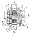
- FIG. 4 is a sectional view of the differential assembly taken along line 4 - 4 of FIG. 2a ;
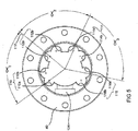
- FIG. 5 is a cross-sectional view of the differential assembly taken along line 5 - 5 of FIG. 4 ;
- FIG. 6 is a perspective view of the differential assembly of FIG. 1 illustrating the cross pin assembly in an exploded condition
- FIG. 7 is a perspective view of the differential assembly of FIG. 1 illustrating the cross pin assembly engaged to the cylindrical boss of the differential casing;
- FIG. 8 is a perspective view of the differential assembly of FIG. 1 illustrating the cross pin assembly in an installed condition
- FIG. 9 is an exploded view of a differential assembly according to other features.
- FIG. 10 is an exploded view of a differential assembly according to other features.
- FIG. 11 is an exploded view of the differential assembly according to other features.
- a drivetrain 10 for an exemplary motor vehicle may include an engine 12, a transmission 14 having an output shaft 16, and a propeller shaft 18 connecting the output shaft 16 to a pinion shaft 20 of a rear axle assembly 22.
- the rear axle assembly 22 includes an axle housing 24, a differential assembly 26 supported in the axle housing 24, and a pair of axle shafts 28 and 30, respectively, interconnected to a left and right rear wheel 32 and 34, respectively.
- the pinion shaft 20 has a pinion shaft gear 36 fixed thereto which drives a ring gear 38 that may be fixed to a differential casing 40 of the differential assembly 26.
- a gearset 42 supported within the differential casing 40 transfers rotary power from the casing 40 to a pair of output shafts 44 and 46 connected to the axle shafts 28 and 30, respectively, and facilitates relative rotation (i.e. differentiation) therebetween.
- the differential assembly 26 is shown in a rear-wheel drive application, the present invention is contemplated for use in differential assemblies installed in transaxles for use in front-wheel drive vehicles, and/or in transfer cases for use in four-wheel drive vehicles.
- the differential assembly 26 may be a parallel-axis helical-gear type differential and includes the differential casing 40, which defines an internal chamber 48.
- the differential casing40 includes a main drum or body 46 and an end cap 50, each of which having respective mating radial flanges 52 and 54, respectively.
- the radial flanges 52 and 54 are secured together by a plurality of bolts (not shown) extending through aligned mounting bores 58.
- a ring or bevel gear can be fixed to the radial flange 52 on the differential casing 40 to transfer rotary power (i.e., drive torque) thereto.
- the differential casing 40 defines a pair of axially aligned openings 60a and 60b in communication with the internal chamber 48.
- the axially aligned openings 60a and 60b are adapted to receive the end segments of the pair of driving output shafts 44 and 46 ( FIG. 1 ), hereinafter referred to as axle shafts.
- the differential assembly 26 includes the gearset 42 that is operable for transferring drive torque from the differential casing 40 to the output shafts 44 and 46 ( FIG. 1 ) in a manner that facilitates speed differential therebetween.
- Gearset 42 may be a helical-type and may be disposed within the internal chamber 48.
- the gearset 42 includes a pair of side gears 68a and 68b.
- the side gears have internal splines 70a and 70b meshed with external splines, not specifically shown, on the corresponding output shafts 44 and 46 ( FIG. 1 ).
- the side gears 68a and 68b include axial hubs 78a and 78b, respectively, which are retained in corresponding annular sockets, formed in the main body 46 and the end cap 50 of the differential casing 40, and annular chambers 82a and 82b.
- a spacer 86 may be located between the side gears 68a and 68b for limiting the amount of axial endplay of the side gears 68a and 68b within the differential case 40.
- a cross pin assembly 90 extends through a clearance passage 92 in the spacer 86 and controls endplay of the axle shafts 44 and 46 ( FIG. 1 ).
- C-shaped retainers, or C-clips 94 may be retained in the annular chambers 82a and 82b for preventing the axle shafts 44 and 46, respectively, from becoming disengaged with the side gears 68a and 68b.
- the side gears 68a and 68b may be bounded at their outer ends by washers 96.
- the gearset 42 includes four sets of pinion pairs, 100a and 100b, 102a and 102b, 104a and 104b and 106a and 106b, respectively ( FIG. 3 ).
- the pinion pairs 100a and 100b, 102a and 102b, 104a and 104b and 106a and 106b are hereinafter referred to as a first, second, third and fourth pair of pinion gears 100, 102, 104 and 106, respectively.
- Brake shoes 100a'-106b' cooperate with respective pinion gears 100 -106.
- the four sets of pinion pairs 100-106 are rotatably supported in complementary sets of pinion bores 110a and 110b, 112a and 112b, 114a and 114b, and 116a and 116b.
- the complementary sets of pinion bores 110a and 110b, 112a and 112b, 114a and 114b, and 116a and 116b are hereinafter referred to as a first, second, third and fourth pair of pinion bores 110, 112, 114, and 116, respectively.
- the pinion bores 110 - 116 are formed in raised hub segments 120 of the main body 46.
- the pinion bores 110-116 are arranged in paired sets such that they communicate with each other and with the internal chamber 48.
- a window opening 124 may be arranged on the differential casing 40 between the first and the fourth pair of pinion gears 100 and 106.
- the four pinion bores 110-116 and as a result, the four pinion pairs 100-106 ( FIG. 3 ), are radially spaced evenly around the differential casing 40 opposite the window opening 124. More specifically, the first pair of pinion bores 110 are offset a radial distance ⁇ 1 from the second pair of pinion bores 112. The second pair of pinion bores 112 are offset a radial distance ⁇ 2 from the third pair of pinion bores 114. The third pair of pinion bores 114 are offset a radial distance ⁇ 3 from the fourth pair of pinion bores 116.
- the respective ⁇ distances are taken from the centerline of respective first bores 110a - 110d.
- the window opening 124 includes an access passage 126 surrounded by a cylindrical boss 128 that may be formed on an outer surface 130 of the differential casing 40.
- the cylindrical boss 128 defines a counterbore 132 having an inner radial engaging surface 136.
- the cylindrical boss 128 includes a pair of mounting passages 140 formed on raised flanges 142 for receiving a fastener 146 ( FIG. 8 ) therethrough.
- a ledge portion 150 extends at least partially about the window opening 124 inwardly of the cylindrical boss 128 on the differential casing 40.
- the cross pin assembly 90 generally includes a proximal head portion 154, an intermediate shank portion 158 and a distal end portion 162.
- the head portion 154 defines a body that may extend generally transverse to the longitudinal axis of the cross pin 90.
- the head portion 154 may include a throughbore 164 for receiving the fastener 146.
- the head portion 154 may include arcuate ends 168 that may be slidably disposed against the inner radial engaging surface 136 of the counterbore 132 during assembly.
- a bottom surface 170 of the head portion 154 locates against the ledge 150.
- the distal end portion 162 of the cross pin assembly 90 locates into a bore 172 formed into incorporated on the differential casing 40.
- the cross pin assembly 90 may be unitarily formed or may comprise two or more components.
- the cross pin 90 is a two-piece assembly comprising the proximal head portion 154, which may be pressed onto a discrete shank that defines both the intermediate shank portion 158 and the distal end portion 162. It is appreciated that while the distal end portion 162 of the cross pin 90 is shown stepped down from the intermediate shank portion 158, the cross pin may comprise a uniform outer diameter.
- an alternate pinion gear arrangement may be employed with a differential assembly providing enough space to accommodate a cross pin defining a consistent outer diameter.
- the spacer passage 92 may be aligned opposite the window opening 124 on the differential casing 40.
- the distal end 162 and the intermediate portion 158 of the cross pin assembly 90 are inserted through the window opening 124 and the spacer passage 92.
- the distal end 162 of the cross pin assembly 90 may be located into the bore 172 on the differential case 40 opposite the window opening 124.
- the bore 172 and the bore 136 pilots the cross pin assembly 90 during installation.
- the proximal head portion 154 may be inserted in an orientation substantially transverse to the axis of the differential casing 40. In this way, the head portion 154 of the cross pin assembly 90 will not interfere with the adjacent ring gear 38 ( FIG. 1 ) during installation.
- the bottom surface 170 of the head portion 154 engages the ledge 150 between the counterbore 132 and the window opening 124.
- the arcuate ends 168 of the proximal head 154 engage the inner radial engaging surface 136 of the counterbore 132.
- the proximal head portion 154 may then be rotated from the position shown in FIG. 7 into a substantially parallel orientation with the axis A of the differential 26 as illustrated in FIG. 8 until the throughbore 164 aligns with the mounting passages 140 of the raised flanges 142 on the cylindrical boss 128.
- the inner radial engaging surface 136 pilots the arcuate ends 168 of the proximal head portion 154.
- the ledge 150 maintains the cross pin assembly 90 at the proper depth and assures that the throughbore 164 will be properly aligned with the mounting passages 140 of the raised flanges 142 on the cylindrical boss 128.
- the fastener 146 may be inserted and secured.
- the cross pin assembly 90 thus installed, relative movement between the cross pin assembly 90 and the differential casing 40 is essentially inhibited.
- the endplay of the axle shafts 44 and 46 may be controlled within desirable tolerances as a function of the diameter of the intermediate portion 158 of the cross pin 90.
- the spacer 86 is disposed between the sidegears 68a and 68b and controls axial endplay of the sidegears 68a and 68b to keep the differential 26 from binding.
- the cross pin 90 does not touch the spacer 86 in an assembled condition.
- the passage 92 in the spacer 86 defines a greater diameter than the diameter of the cross pin 90.
- two distinct components are used to control the side gear endplay (namely, the spacer 86), and the axle shaft endplay (namely, the cross pin 90).
- Such an arrangement allows for a desired amount of side gear endplay without affecting the axle shaft endplay.
- the mass of the differential assembly 26 may be distributed to provide rotational balance. Specifically, the mass of the cylindrical boss 128 and the cross pin head 154 cooperate with the mass of the differential casing 40 around the pinion bores 110-116 and the mass of the pinion gears 100 - 106 to provide a rotationally balanced differential assembly 26. Stated another way, the mass of the several components of the differential assembly 26 are distributed about the rotational axis A so as to minimize or eliminate imbalance when the differential assembly 26 is rotated about the rotational axis A. It is appreciated that a counter weight may additionally, or alternatively be incorporated onto the differential casing 40 or the end cap 50 of the differential assembly 26.
- the fastener 146 may be configured the same as an open differential such that the same axle assembly lines may be ran with both open differentials and helical gear differentials without changing tooling or torque wrench settings.
- the differential assembly 226 incorporates like components as the differential assembly 26 and are identified with a 200 prefix.
- the differential assembly 226 includes a cross pin 290 having an intermediate shank portion 258 and a distal end portion 262.
- the cross pin 290 may be adapted to be retained in the differential case 240 by a retaining disk 234.
- the proximal end of the cross pin 290 may be adapted to recess into a counterbore 238 formed on an inboard surface of the retaining disk 234.
- a retaining ring 244 may be adapted to seat into a radial lip 248 arranged on the counterbore 232 in an assembled position.
- the differential assembly 326 incorporates like components as the differential assembly 26 and are identified with a 300 prefix.
- the differential assembly 326 includes a cross pin 390 having an intermediate shank portion 358 and a distal end portion 362.
- the cross pin 390 may be adapted to be retained in the differential case 340 by an L-plate 334 and a fastener 340.
- a proximal end of the cross pin 390 may be adapted to pass through an opening 338 arranged on the L-plate 334. In this way, the L-plate cooperates with the cross pin 390 to maintain the cross pin 390 in a substantially perpendicular orientation with axis A.
- the fastener 340 may be adapted to be secured through passages 348 incorporated in flange portions 332 and a passage 335 arranged in the L-plate 334. As a result, in an installed position, the fastener 340 bounds the proximal end of the cross pin 290 and maintains the cross pin 290 in an installed position.
- the differential assembly 426 incorporates like components as the differential assembly 26 and are identified with a 400 prefix.
- the differential assembly 426 includes a cross pin 490 having an intermediate shank portion 458 and a distal end portion 462.
- the cross pin 490 may be adapted to be retained in the differential casing 440 by a fastener 440.
- the fastener 440 may be adapted to be secured through passages 448 incorporated in flange portions 432 and a passage 435 arranged in the cross pin 490.
- An access passage 426 may be incorporated in the differential casing 440 and defines an access for installing C-clips 92 ( FIG. 3 ).
- a spacer 486 according to additional features includes a passage 492 for accepting the cross pin 490 therethrough in an assembled position. The spacer 486 may be adapted to be installed into the differential casing 440 axially and be positioned between side gears as described herein.
Landscapes
- Engineering & Computer Science (AREA)
- General Engineering & Computer Science (AREA)
- Mechanical Engineering (AREA)
- Chemical & Material Sciences (AREA)
- Combustion & Propulsion (AREA)
- Transportation (AREA)
- Retarders (AREA)
Abstract
Description
- The present invention relates to differentials for use in automotive drivelines and, more particularly, to a pinion pair arrangement for a four pinion pair, C-clip differential having independent control of side gear endplay and axle shaft endplay.
- Differentials of the type used in automotive drivelines generally include a planetary gearset supported within a differential casing to facilitate relative rotation (i.e., speed differentiation) between a pair of output shafts. The planetary gearset typically includes helical side gears fixed to the end of the output shafts, which are meshed with paired sets of helical pinion gears. This type of differentiation is known as a parallel axis helical gear differential. In response to input torque applied to the differential case, the torque transmitted through meshed engagement of the side gears and pinion gears generates thrust forces. To accommodate these and other operating forces, the wall surface of the gear pockets and other thrust surfaces of the differential casing must provide adequate support.
- In some differentials it is necessary to install C-shaped retainers, or C-clips for restraining and positioning the output shafts in the differentials. To install the C-clips it is necessary to gain access to the interior cavity of the differential casing through an access window arranged on the differential casing.
- In general, it is desirable to allow the side gear loading to be spread out evenly around the periphery of the differential. One way to achieve even loading is to position the pinion pairs evenly around the periphery of the differential casing. However, because the access window is arranged on the outer periphery of the differential casing, there tends to be incompatibility issues with placement of the pinion pairs.
- A differential assembly for a vehicle includes a differential casing rotatable about an axis. A pair of side gears are disposed within the differential casing. A first, second, third and fourth pair of pinion bores are formed in the differential casing. A first, second, third and fourth pair of pinion gears are slidably and rotatably disposed in the first, second, third and fourth pair of pinion bores respectively. A window opening is formed in the differential casing between the first and fourth pair of pinion gears. The second pair of pinion bores are radially offset an equivalent distance from the first and third pair of pinion bores. The third pair of pinion bores are radially offset an equivalent distance from the second and the fourth pair of pinion bores.
- According to other features a spacer is disposed between the pair of side gears in the differential casing. A cross pin extends substantially transverse to the axis and through a passage in the spacer. The cross pin includes a proximal head portion, which is secured to the differential casing proximate to the window opening. An intermediate shank portion passes through the passage in the spacer. A distal end portion is piloted in a bore formed in the differential casing.
- A differential assembly for a vehicle includes a differential casing rotatable about an axis and communicating with a first and second axle shaft. A window opening is formed in the differential casing. A pair of side gears are disposed within the differential casing. A spacer is disposed between the pair of side gears and limits inward movement of the side gears, the spacer including a passage therein. A cross pin extends generally transverse to the axis and through the differential casing, the cross pin passing through the passage in the spacer and limiting inward movement of the first and second axle shafts. The cross pin limits inward movement of the first and second axle shafts independently of the spacer limiting inward movement of the side gears.
- A method of assembling a first and second side gear within a differential casing includes locating a spacer between the first and second side gear. A cross pin is inserted through the window opening and the spacer passage. The cross pin is adapted to limit axial movement of the axle shafts while remaining clear of contact from the spacer. A distal end portion of the cross pin is located into a bore on the differential casing. The cross pin is secured to the differential casing at the window opening.
- Further areas of applicability of the present invention will become apparent from the detailed description provided hereinafter. It should be understood that the detailed description and specific examples, while indicating the preferred embodiment of the invention, are intended for purposes of illustration only and are not intended to limit the scope of the invention.
- The present invention will become more fully understood from the detailed description and the accompanying drawings, wherein:
-
FIG. 1 is a schematic view of an exemplary motor vehicle into which a differential assembly constructed in accordance with the teachings of the present invention is incorporated; -
FIG. 2a is a perspective view of the differential assembly ofFIG. 1 ; -
FIG. 2b is a perspective view of the differential casing ofFIG. 1 ; -
FIG. 3 is an exploded view of the differential assembly ofFIG. 1 ; -
FIG. 4 is a sectional view of the differential assembly taken along line 4 - 4 ofFIG. 2a ; -
FIG. 5 is a cross-sectional view of the differential assembly taken along line 5 - 5 ofFIG. 4 ; -
FIG. 6 is a perspective view of the differential assembly ofFIG. 1 illustrating the cross pin assembly in an exploded condition; -
FIG. 7 is a perspective view of the differential assembly ofFIG. 1 illustrating the cross pin assembly engaged to the cylindrical boss of the differential casing; -
FIG. 8 is a perspective view of the differential assembly ofFIG. 1 illustrating the cross pin assembly in an installed condition; -
FIG. 9 is an exploded view of a differential assembly according to other features; -
FIG. 10 is an exploded view of a differential assembly according to other features; and -
FIG. 11 is an exploded view of the differential assembly according to other features. - The following description of the preferred embodiment(s) is merely exemplary in nature and is in no way intended to limit the invention, its application, or uses. The differential assembly according to the present teachings may be utilized with a wide variety of applications and is not intended to be specifically limited to the particular application recited herein.
- With initial reference to
FIG. 1 , adrivetrain 10 for an exemplary motor vehicle may include anengine 12, atransmission 14 having anoutput shaft 16, and apropeller shaft 18 connecting theoutput shaft 16 to apinion shaft 20 of arear axle assembly 22. Therear axle assembly 22 includes anaxle housing 24, adifferential assembly 26 supported in theaxle housing 24, and a pair ofaxle shafts rear wheel pinion shaft 20 has apinion shaft gear 36 fixed thereto which drives aring gear 38 that may be fixed to adifferential casing 40 of thedifferential assembly 26. Agearset 42 supported within thedifferential casing 40 transfers rotary power from thecasing 40 to a pair ofoutput shafts axle shafts differential assembly 26 is shown in a rear-wheel drive application, the present invention is contemplated for use in differential assemblies installed in transaxles for use in front-wheel drive vehicles, and/or in transfer cases for use in four-wheel drive vehicles. - Turning now to
FIGS. 2a - 4 , thedifferential assembly 26 will be described in further detail. Thedifferential assembly 26 may be a parallel-axis helical-gear type differential and includes thedifferential casing 40, which defines aninternal chamber 48. The differential casing40 includes a main drum orbody 46 and anend cap 50, each of which having respectivemating radial flanges radial flanges radial flange 52 on thedifferential casing 40 to transfer rotary power (i.e., drive torque) thereto. Thedifferential casing 40 defines a pair of axially alignedopenings internal chamber 48. The axially alignedopenings output shafts 44 and 46 (FIG. 1 ), hereinafter referred to as axle shafts. - With specific reference to
FIGS. 3 and4 , thedifferential assembly 26 includes thegearset 42 that is operable for transferring drive torque from thedifferential casing 40 to theoutput shafts 44 and 46 (FIG. 1 ) in a manner that facilitates speed differential therebetween.Gearset 42 may be a helical-type and may be disposed within theinternal chamber 48. Thegearset 42 includes a pair of side gears 68a and 68b. The side gears haveinternal splines 70a and 70b meshed with external splines, not specifically shown, on thecorresponding output shafts 44 and 46 (FIG. 1 ). In addition, the side gears 68a and 68b includeaxial hubs main body 46 and theend cap 50 of thedifferential casing 40, andannular chambers spacer 86 may be located between the side gears 68a and 68b for limiting the amount of axial endplay of the side gears 68a and 68b within thedifferential case 40. Across pin assembly 90 extends through aclearance passage 92 in thespacer 86 and controls endplay of theaxle shafts 44 and 46 (FIG. 1 ). - C-shaped retainers, or C-
clips 94, may be retained in theannular chambers axle shafts washers 96. - The
gearset 42 includes four sets of pinion pairs, 100a and 100b, 102a and 102b, 104a and 104b and 106a and 106b, respectively (FIG. 3 ). For clarity the pinion pairs 100a and 100b, 102a and 102b, 104a and 104b and 106a and 106b are hereinafter referred to as a first, second, third and fourth pair of pinion gears 100, 102, 104 and 106, respectively.Brake shoes 100a'-106b' cooperate with respective pinion gears 100 -106. - In
FIGS. 2b and3 , the four sets of pinion pairs 100-106 are rotatably supported in complementary sets of pinion bores 110a and 110b, 112a and 112b, 114a and 114b, and 116a and 116b. The complementary sets of pinion bores 110a and 110b, 112a and 112b, 114a and 114b, and 116a and 116b are hereinafter referred to as a first, second, third and fourth pair of pinion bores 110, 112, 114, and 116, respectively. The pinion bores 110 - 116 are formed in raisedhub segments 120 of themain body 46. The pinion bores 110-116 are arranged in paired sets such that they communicate with each other and with theinternal chamber 48. In addition, the pinion bores 110-116 are aligned substantial parallel to the rotational axis A of theaxle shafts 44 and 46 (FIG. 1 ). Awindow opening 124 may be arranged on thedifferential casing 40 between the first and the fourth pair of pinion gears 100 and 106. - With reference now to
FIG. 5 , the spacial relationship of the pinion pairs will be described. The four pinion bores 110-116, and as a result, the four pinion pairs 100-106 (FIG. 3 ), are radially spaced evenly around thedifferential casing 40 opposite thewindow opening 124. More specifically, the first pair of pinion bores 110 are offset a radial distance α1 from the second pair of pinion bores 112. The second pair of pinion bores 112 are offset a radial distance α2 from the third pair of pinion bores 114. The third pair of pinion bores 114 are offset a radial distance α3 from the fourth pair of pinion bores 116. As illustrated, the respective α distances are taken from the centerline of respectivefirst bores 110a - 110d. The radial offsets between the pinion bores 110 and 112, 112 and 114, and 114 and 116 may be approximately equivalent (e.g., α1 = α2 = α3). In the example provided, α1, α2 and α3 are approximately 75 degrees. - With specific reference now to
FIGS. 2b ,4 and6 , the configuration of thewindow opening 124 and the cooperation of thecross pin assembly 90 will be described. Thewindow opening 124 includes anaccess passage 126 surrounded by acylindrical boss 128 that may be formed on anouter surface 130 of thedifferential casing 40. Thecylindrical boss 128 defines acounterbore 132 having an innerradial engaging surface 136. Thecylindrical boss 128 includes a pair of mountingpassages 140 formed on raisedflanges 142 for receiving a fastener 146 (FIG. 8 ) therethrough..Aledge portion 150 extends at least partially about thewindow opening 124 inwardly of thecylindrical boss 128 on thedifferential casing 40. - The
cross pin assembly 90 generally includes aproximal head portion 154, anintermediate shank portion 158 and adistal end portion 162. Thehead portion 154 defines a body that may extend generally transverse to the longitudinal axis of thecross pin 90. Thehead portion 154 may include athroughbore 164 for receiving thefastener 146. Thehead portion 154 may include arcuate ends 168 that may be slidably disposed against the innerradial engaging surface 136 of thecounterbore 132 during assembly. Abottom surface 170 of thehead portion 154 locates against theledge 150. Thedistal end portion 162 of thecross pin assembly 90 locates into abore 172 formed into incorporated on thedifferential casing 40. - The
cross pin assembly 90 may be unitarily formed or may comprise two or more components. In the example provided, thecross pin 90 is a two-piece assembly comprising theproximal head portion 154, which may be pressed onto a discrete shank that defines both theintermediate shank portion 158 and thedistal end portion 162. It is appreciated that while thedistal end portion 162 of thecross pin 90 is shown stepped down from theintermediate shank portion 158, the cross pin may comprise a uniform outer diameter. For example, an alternate pinion gear arrangement may be employed with a differential assembly providing enough space to accommodate a cross pin defining a consistent outer diameter. - With reference to
FIGS. 4 and7 , assembly of thecross pin assembly 90 into thedifferential casing 40 will now be described in greater detail. Once the C-clips 94 are properly located and thespacer 86 is located between the side gears 66a and 66b, thespacer passage 92 may be aligned opposite thewindow opening 124 on thedifferential casing 40. Thedistal end 162 and theintermediate portion 158 of thecross pin assembly 90 are inserted through thewindow opening 124 and thespacer passage 92. Thedistal end 162 of thecross pin assembly 90 may be located into thebore 172 on thedifferential case 40 opposite thewindow opening 124. Thebore 172 and thebore 136 pilots thecross pin assembly 90 during installation. Theproximal head portion 154 may be inserted in an orientation substantially transverse to the axis of thedifferential casing 40. In this way, thehead portion 154 of thecross pin assembly 90 will not interfere with the adjacent ring gear 38 (FIG. 1 ) during installation. - As the
distal end 162 of thecross pin assembly 90 locates into thebore 172, thebottom surface 170 of thehead portion 154 engages theledge 150 between thecounterbore 132 and thewindow opening 124. Similarly, the arcuate ends 168 of theproximal head 154 engage the innerradial engaging surface 136 of thecounterbore 132. Theproximal head portion 154 may then be rotated from the position shown inFIG. 7 into a substantially parallel orientation with the axis A of the differential 26 as illustrated inFIG. 8 until thethroughbore 164 aligns with the mountingpassages 140 of the raisedflanges 142 on thecylindrical boss 128. During rotation of theproximal head portion 154, the innerradial engaging surface 136 pilots the arcuate ends 168 of theproximal head portion 154. Concurrently, theledge 150 maintains thecross pin assembly 90 at the proper depth and assures that thethroughbore 164 will be properly aligned with the mountingpassages 140 of the raisedflanges 142 on thecylindrical boss 128. - With the
throughbore 164 and the mountingpassages 140 aligned to one another, thefastener 146 may be inserted and secured. With thecross pin assembly 90 thus installed, relative movement between thecross pin assembly 90 and thedifferential casing 40 is essentially inhibited. As a result, the endplay of theaxle shafts 44 and 46 (FIG. 1 ) may be controlled within desirable tolerances as a function of the diameter of theintermediate portion 158 of thecross pin 90. Thespacer 86 is disposed between thesidegears sidegears cross pin 90 does not touch thespacer 86 in an assembled condition. Thepassage 92 in thespacer 86 defines a greater diameter than the diameter of thecross pin 90. In this way, two distinct components are used to control the side gear endplay (namely, the spacer 86), and the axle shaft endplay (namely, the cross pin 90). Such an arrangement allows for a desired amount of side gear endplay without affecting the axle shaft endplay. - The mass of the
differential assembly 26 may be distributed to provide rotational balance. Specifically, the mass of thecylindrical boss 128 and thecross pin head 154 cooperate with the mass of thedifferential casing 40 around the pinion bores 110-116 and the mass of the pinion gears 100 - 106 to provide a rotationally balanceddifferential assembly 26. Stated another way, the mass of the several components of thedifferential assembly 26 are distributed about the rotational axis A so as to minimize or eliminate imbalance when thedifferential assembly 26 is rotated about the rotational axis A. It is appreciated that a counter weight may additionally, or alternatively be incorporated onto thedifferential casing 40 or theend cap 50 of thedifferential assembly 26. - The
fastener 146 may be configured the same as an open differential such that the same axle assembly lines may be ran with both open differentials and helical gear differentials without changing tooling or torque wrench settings. - Turning now to
FIG. 9 , adifferential assembly 226 according to other features is shown. Thedifferential assembly 226 incorporates like components as thedifferential assembly 26 and are identified with a 200 prefix. Thedifferential assembly 226 includes across pin 290 having anintermediate shank portion 258 and adistal end portion 262. Thecross pin 290 may be adapted to be retained in thedifferential case 240 by aretaining disk 234. Specifically, the proximal end of thecross pin 290 may be adapted to recess into acounterbore 238 formed on an inboard surface of theretaining disk 234. A retainingring 244 may be adapted to seat into aradial lip 248 arranged on thecounterbore 232 in an assembled position. - With reference now to
FIG. 10 , adifferential assembly 326 according to additional features is shown. Thedifferential assembly 326 incorporates like components as thedifferential assembly 26 and are identified with a 300 prefix. Thedifferential assembly 326 includes across pin 390 having anintermediate shank portion 358 and adistal end portion 362. Thecross pin 390 may be adapted to be retained in thedifferential case 340 by an L-plate 334 and afastener 340. Specifically, a proximal end of thecross pin 390 may be adapted to pass through anopening 338 arranged on the L-plate 334. In this way, the L-plate cooperates with thecross pin 390 to maintain thecross pin 390 in a substantially perpendicular orientation with axis A. Thefastener 340 may be adapted to be secured throughpassages 348 incorporated inflange portions 332 and apassage 335 arranged in the L-plate 334. As a result, in an installed position, thefastener 340 bounds the proximal end of thecross pin 290 and maintains thecross pin 290 in an installed position. - With reference now to
FIG. 11 , adifferential assembly 426 according to additional features is shown. Thedifferential assembly 426 incorporates like components as thedifferential assembly 26 and are identified with a 400 prefix. Thedifferential assembly 426 includes across pin 490 having anintermediate shank portion 458 and adistal end portion 462. Thecross pin 490 may be adapted to be retained in thedifferential casing 440 by afastener 440. Specifically, thefastener 440 may be adapted to be secured throughpassages 448 incorporated inflange portions 432 and apassage 435 arranged in thecross pin 490. - An
access passage 426 may be incorporated in thedifferential casing 440 and defines an access for installing C-clips 92 (FIG. 3 ). Aspacer 486 according to additional features includes apassage 492 for accepting thecross pin 490 therethrough in an assembled position. Thespacer 486 may be adapted to be installed into thedifferential casing 440 axially and be positioned between side gears as described herein. - While the invention has been described in the specification and illustrated in the drawings with reference to various embodiments, it will be understood by those skilled in the art that various changes may be made and equivalents may be substituted for elements thereof without departing from the scope of the invention as defined in the claims. Furthermore, the mixing and matching of features, elements and/or functions between various embodiments is expressly contemplated herein so that one of ordinary skill in the art would appreciate from this disclosure that features, elements and/or functions of one embodiment may be incorporated into another embodiment as appropriate, unless described otherwise, above. Moreover, many modifications may be made to adapt a particular situation or material to the teachings of the invention without departing from the essential scope thereof. Therefore, it is intended that the invention not be limited to the particular embodiment illustrated by the drawings and described in the specification as the best mode presently contemplated for carrying out this invention, but that the invention will include any embodiments falling within the foregoing description and the appended claims.
The following embodiments were subject matter for claims in the original application: - 1. A differential assembly for a vehicle comprising:
- a differential casing rotatable about an axis,
- a pair of side gears disposed within said differential casing,
- a first, second, third and fourth pair of pinion bores formed in said differential casing;
- a first, second, third and fourth pair of pinion gears slidably and rotatably disposed in said first, second, third and fourth pair of pinion bores, respectively; and
- a window opening formed in said differential casing between said first and fourth pair of pinion gears;
- wherein said second pair of pinion bores are radially offset an equivalent distance from said first and third pair of pinion bores, and wherein said third pair of pinion bores are radially offset an equivalent distance from said second and fourth pair of pinion bores.
- 2. The differential assembly of embodiment 1 wherein a spacer is disposed between said pair of side gears in said differential casing.
- 3. The differential assembly of
embodiment 2 further comprising a cross pin extending substantially transverse to said axis and through a passage in said spacer. - 4. The differential assembly of embodiment 3 wherein said cross pin includes a proximal head portion, which is secured to said differential casing proximate said window opening, an intermediate shank portion, which passes through said passage in said spacer, and a distal end portion that is piloted in a bore formed in the differential casing.
- 5. The differential assembly of embodiment 4 wherein said distal end portion is stepped down from said intermediate shank portion.
- 6. The differential assembly of embodiment 4 wherein said window opening includes an access passage surrounded by a boss that extends from an outer surface of said differential casing, wherein said proximal head portion of said cross pin is received by said boss.
- 7. The differential assembly of embodiment 6 wherein said boss includes at least one mounting passage formed thereon for receiving a fastener therethrough, said fastener extending through said head of said cross pin.
- 8. The differential assembly of embodiment 7 wherein a mass of said cylindrical boss and said cross pin head cooperate with a mass of said differential casing around said first, second, third and fourth pinion bores and mass of said respective pinion gears around said differential casing to rotationally balance the differential assembly about the axis.
- 9. A differential assembly for a vehicle comprising:
- a differential casing rotatable about an axis and communicating with a first and second axle shaft;
- a window opening formed in said differential casing;
- a pair of side gears disposed within said differential casing;
- a spacer disposed between said pair of side gears and limiting inward movement of said side gears, said spacer having a passage therein; and
- a cross pin extending generally transverse to said axis and through said differential casing, said cross pin passing through said passage in said spacer, said cross pin limiting inward movement of said first and second axle shafts;
- wherein said cross pin limits inward movement of said first and second axle shafts independently of said spacer limiting inward movement of said side gears.
- 10. The differential assembly of embodiment 9 wherein said cross pin includes a proximal head portion secured to said differential casing at said window opening.
- 11. The differential assembly of
embodiment 10 wherein said window opening includes an access passage surrounded by a boss extending on an outer surface of said differential casing, said proximal head portion received by said boss in said installed position. - 12. The differential assembly of embodiment 11 wherein said boss includes at least one mounting passage formed thereon for receiving a fastener therethrough, said fastener restraining said cross pin in said installed position.
- 13. The differential assembly of
embodiment 12 wherein said cross pin is rotatable between an installation orientation wherein a longitudinal body of said proximal head portion is substantially transverse to said axis and an installed orientation whereby said longitudinal body is substantially parallel to said axis. - 14. The differential assembly of embodiment 13 wherein said longitudinal body of said cross pin includes arcuate ends for slidably engaging an arcuate surface of said boss during rotation between said installation orientation and said installed orientation.
- 15. The differential assembly of
embodiment 14 wherein a ledge portion extends between said window opening and said boss on said differential casing, said longitudinal body bounded on an inboard surface by said ledge portion in said installed position. - 16. A method of assembling a first and second side gear within a differential casing, the differential casing cooperating with an input and output shaft in an assembled position, the method comprising:
- locating a spacer between the first and second side gear, said spacer adapted to limit axial movement of said side gears;
- inserting a cross pin through said window opening and said spacer passage, said cross pin adapted to limit axial movement of said axle shafts while remaining clear of contact from said spacer;
- locating a distal end portion of said cross pin into a bore on the differential casing; and
- securing said cross pin to the differential casing at said window opening.
- 17. The method of
embodiment 16 wherein inserting a cross pin through said window opening includes, orienting a longitudinal body of a proximal head portion in a generally transverse orientation from said rotatable axis. - 18. The method of embodiment 17 wherein inserting a cross pin through said window opening includes inserting, said cross pin until said longitudinal body engages a counterbore formed around said window opening.
- 19. The method of
embodiment 16 wherein securing a proximal head portion of said cross pin comprises:- rotating said longitudinal body from said transverse orientation to a generally parallel orientation with said rotatable axis;
- aligning a bore on said longitudinal body with a mounting passage arranged on the differential casing; and
- securing a fastener through said mounting passage and said bore.
- 20. The method of
embodiment 16 wherein securing said cross pin to the differential casing comprises:- passing a fastener through a passage in the cross pin; and
- securing said fastener to a retaining flange arranged on the differential casing.
- 21. The method of
embodiment 16 wherein securing said cross pin to the differential casing comprises:- locating a retaining member at a proximal end of the cross pin; and
- securing a retaining ring to the differential casing thereby bonding said retaining member and said cross pin in a retained position with the differential casing.
- 22. The differential assembly comprising:
- a differential casing that is rotatable about as axis, the differential casing defining a central bores, a first set of pinion bores, a second set of pinion bores, a third set of pinion bores, a fourth set of pinion bores and a window, each of the first, second, third and fourth sets of pinion bores including a first bore and a second bore, each of the first and second bores having a center;
- wherein a first angle between the centers of the first bores in the first and second sets of pinion bores is approximately equal to a second angle between the centers of the first bores in the third and fourth sets of pinion bores; and
- wherein a third angle between the first bores in the second and third sets of pinion bores is smaller than a fourth angle between the first bores in the first and fourth sets of pinion bores.
- 23. The differential assembly of
embodiment 22, wherein the third angle is approximately equal to the first angle. - 24. The differential assembly of embodiment 23, wherein the first angle is about 70° to about 80°.
- 25. The differential assembly of
embodiment 24, wherein the first angle is about 75°. - 26. The differential assembly of
embodiment 22, wherein the first and fourth sets of pinion bores are mirrored about a plane that passes through the differential casing and which includes the rotational axis and an axis of the window. - 27. The differential assembly of
embodiment 26, wherein the second and third sets of pinion bores are mirrored about the plane.
Claims (15)
- A differential assembly (26) for a vehicle equipped with axle shafts (28, 30), the differential assembly (26) comprising:a differential casing (40) rotatable about an axis (A), the differential casing (40) including a window opening (124) having a ledge portion (150); a ring gear (38) fixed to the differential casing (40);a pair of side gears (68a, 68b) disposed within the differential casing (40) and adapted to drivingly engage the axle shafts (28, 30);a spacer (86) disposed between the side gears (68a, 68b), the spacer (86) having a clearance passage (92); anda cross pin (90) having an intermediate portion (158) and a transversely extending head portion (154), the intermediate portion (158) being received into the window opening (124) and the clearance passage (92), wherein the transversely extending head portion (154) is positioned at a first orientation during receipt of the cross pin (90) into the window opening (124) to clear the ring gear (38), the transversely extending head portion (154) engaging the ledge portion (150) to limit axial movement of the cross pin (90) relative to the differential casing (40), the transversely extending head portion (154) being rotated to a second orientation when coupled to the differential casing (40);wherein the cross pin (90) is adapted to limit movement of the axle shafts (28, 30) in a direction toward one another and the spacer (86) limits movement of the side gears (68a, 68b) toward one another.
- The differential assembly (26) of claim 1, wherein the spacer (86) is substantially U-shaped.
- The differential assembly (26) of claim 1, wherein the first orientation and the second orientation differ by approximately 90 degrees.
- The differential assembly (26) of claim 3, wherein a distal end portion (162) of the cross pin (90) opposite the transversely extending head portion (154) is received in another aperture (172) formed in the differential casing (40).
- The differential assembly (26) of claim 1, wherein a threaded fastener (146) removably couples the cross pin (90) to the differential casing (40).
- The differential assembly (26) of claim 5, wherein the differential casing (40) includes radially extending spaced apart flanges (142) having mounting passages (140) in receipt of the threaded fastener (146).
- The differential assembly (26) of claim 1, further comprising a plurality of pinion pairs (100, 102, 104, 106), each pinion pair having a first pinion (100a, 102a, 104a, 106a) and a second pinion (100b, 102b, 104b, 106b), the pinion pairs (100, 102, 104, 106) being received into first, second, third and fourth pinion bores (110, 112, 114, 116) formed in the differential casing (40), wherein the second pinion bores (112) are spaced apart from the first pinion bores (110) by a first angle (α1), the third pair of pinion bores (104) are spaced apart from the second pinion bores (102) by a second angle (α2), the fourth pair of pinion bores (116) are spaced apart from the third pinion bores (104) by a third angle (α3), and wherein each of the first, second and third angles (α1, α2, α3) are less than 90 degrees in magnitude such that the first and fourth pinion bores (110, 116) are spaced apart by an angle that exceeds 90 degrees in magnitude.
- The differential assembly of Claim 7, wherein the first and third angles (α1, α3) are equal.
- The differential assembly of Claim 8, wherein the first and second angles (α1, α2) are equal.
- The differential assembly of Claim 8, wherein the first angle (α1) is 75 degrees in magnitude.
- The differential assembly of Claim 7, wherein the first and second angles (α1, α2) are equal.
- The differential assembly of Claim 1, wherein further comprising a plurality of pinion pairs (100, 102, 104, 106) and a plurality of brake shoes (100a', 100b', 102a', 102b', 104a', 104b', 106a', 106b'), each pinion pair having a first pinion (100a, 102a, 104a, 106a) and a second pinion (100b, 102b, 104b, 106b), the pinion pairs (100, 102, 104, 106) being received into first, second, third and fourth pinion bores (110, 112, 114, 116) formed in the differential casing (40), wherein each of the first pinions (100a, 102a, 104a, 106a) has one of the brake shoes (100a', 100b', 102a', 102b', 104a', 104b', 106a', 106b') mounted thereon.
- The differential assembly of Claim 12, wherein each of the second pinions (100b, 102b, 104b, 106b) has one of the brake shoes (100a', 100b', 102a', 102b', 104a', 104b', 106a', 106b') mounted thereon.
- The differential assembly of Claim 1, wherein the transversely extending head portion (154) defines arcuate ends (168) that engage an inner radial engaging surface (136) of the window opening (124).
- The differential assembly of Claim 1, further comprising a pair of C-shaped clips (94), each C-shaped dip (94) being configured to prevent one of the axle shafts (44, 45) from disengaging a corresponding one of the side gears (68a, 68b).
Applications Claiming Priority (2)
| Application Number | Priority Date | Filing Date | Title |
|---|---|---|---|
| US10/794,780 US7022041B2 (en) | 2004-03-05 | 2004-03-05 | Helical gear differential |
| EP05004549A EP1571373B1 (en) | 2004-03-05 | 2005-03-02 | Helical gear differential |
Related Parent Applications (1)
| Application Number | Title | Priority Date | Filing Date |
|---|---|---|---|
| EP05004549.1 Division | 2005-03-02 |
Publications (2)
| Publication Number | Publication Date |
|---|---|
| EP2450598A1 true EP2450598A1 (en) | 2012-05-09 |
| EP2450598B1 EP2450598B1 (en) | 2013-10-09 |
Family
ID=34750644
Family Applications (2)
| Application Number | Title | Priority Date | Filing Date |
|---|---|---|---|
| EP12151384.0A Expired - Fee Related EP2450598B1 (en) | 2004-03-05 | 2005-03-02 | Helical gear differential |
| EP05004549A Expired - Fee Related EP1571373B1 (en) | 2004-03-05 | 2005-03-02 | Helical gear differential |
Family Applications After (1)
| Application Number | Title | Priority Date | Filing Date |
|---|---|---|---|
| EP05004549A Expired - Fee Related EP1571373B1 (en) | 2004-03-05 | 2005-03-02 | Helical gear differential |
Country Status (5)
| Country | Link |
|---|---|
| US (3) | US7022041B2 (en) |
| EP (2) | EP2450598B1 (en) |
| JP (2) | JP4828136B2 (en) |
| KR (1) | KR100785691B1 (en) |
| BR (1) | BRPI0500676B1 (en) |
Families Citing this family (34)
| Publication number | Priority date | Publication date | Assignee | Title |
|---|---|---|---|---|
| US7022041B2 (en) | 2004-03-05 | 2006-04-04 | American Axle & Manufacturing, Inc. | Helical gear differential |
| US7232397B2 (en) * | 2005-04-27 | 2007-06-19 | American Axle & Manufacturing, Inc. | Axleshaft retention assembly for differentials and method of assembly |
| US7341536B2 (en) * | 2005-10-20 | 2008-03-11 | Dana Corporation | Light weight differential case half |
| US20080090692A1 (en) * | 2006-10-17 | 2008-04-17 | Gates Luther H | Transfer case center differential |
| US7837588B2 (en) * | 2007-07-20 | 2010-11-23 | American Axle & Manufacturing, Inc. | Pre-load mechanism for helical gear differential |
| US8070641B2 (en) * | 2007-08-14 | 2011-12-06 | Autotech Sport Tuning Corporation | Differential gear assembly |
| US7648438B2 (en) * | 2007-08-17 | 2010-01-19 | American Axle & Manufacturing, Inc. | Differential with cross pin retention system and method for assembly |
| US9347542B2 (en) * | 2008-09-30 | 2016-05-24 | American Axle & Manufacturing, Inc. | Parallel-axis helical differential assembly |
| DE112010004718T5 (en) | 2009-12-08 | 2012-09-20 | American Axle & Manufacturing, Inc. | Detachable rear drive axle for longitudinally arranged drive trains |
| US8690690B2 (en) | 2010-06-30 | 2014-04-08 | American Axle & Manufacturing, Inc. | Constant velocity joint with quick connector and method |
| US9731598B2 (en) | 2010-07-23 | 2017-08-15 | Fca Us Llc | Multi-mode drive system for transaxle applications |
| WO2012135738A2 (en) | 2011-04-01 | 2012-10-04 | American Axle & Manufacturing, Inc. | Differential assembly |
| CN102401107A (en) * | 2011-11-10 | 2012-04-04 | 韩昌利 | Mechanical locking antiskid differential |
| US8460149B1 (en) | 2013-01-25 | 2013-06-11 | American Axle & Manufacturing, Inc. | Differential bearing system for a power transmitting component and method for assembling a power transmitting component |
| US9254713B2 (en) | 2013-03-15 | 2016-02-09 | American Axle & Manufacturing, Inc. | Axle assembly with inboard axle shaft bearings that support a differential mechanism |
| US9103427B2 (en) | 2013-03-15 | 2015-08-11 | American Axle & Manufacturing, Inc. | Axle assembly |
| US9028358B2 (en) | 2013-03-15 | 2015-05-12 | American Axle & Manufacturing, Inc. | Disconnecting axle assembly |
| US9157515B2 (en) | 2013-03-15 | 2015-10-13 | American Axle & Manufacturing, Inc. | Axle assembly |
| US9249872B2 (en) | 2013-03-15 | 2016-02-02 | American Axle & Manufacturing, Inc. | Axle assembly having an angular contact bearing that supports a ring gear for rotation on an axle housing |
| USD767658S1 (en) | 2013-08-13 | 2016-09-27 | Eaton Corporation | Helical gear differential housing |
| USD711445S1 (en) | 2013-08-13 | 2014-08-19 | Eaton Corporation | Helical gear differential housing |
| DE102013220393A1 (en) * | 2013-10-10 | 2015-04-16 | Zf Friedrichshafen Ag | Securing means for securing an axial stop element on a shaft |
| US9022892B1 (en) | 2014-04-23 | 2015-05-05 | American Axle & Manufacturing, Inc. | Axle assembly having differential assembly with inverted differential bearings |
| CN105317965B (en) * | 2014-07-31 | 2018-08-17 | 美国轮轴制造公司 | Disconnect shaft assembly |
| US9587692B2 (en) | 2015-04-01 | 2017-03-07 | Akebono Brake Industry Co., Ltd | Differential for a parking brake assembly |
| USD806132S1 (en) * | 2015-11-09 | 2017-12-26 | Eaton Corporation | Spring slider |
| US10267401B2 (en) | 2015-11-25 | 2019-04-23 | American Axle & Manufacturing, Inc. | Axle assembly |
| CN108700183B (en) | 2016-03-25 | 2022-05-06 | 美国轮轴制造公司 | Disconnected axle assembly |
| USD900874S1 (en) * | 2016-11-17 | 2020-11-03 | Eaton Intelligent Power Limited | Differential case |
| USD941880S1 (en) | 2018-01-19 | 2022-01-25 | Eaton Intelligent Power Limited | Differential case |
| US10927937B2 (en) | 2018-09-06 | 2021-02-23 | American Axle & Manufacturing, Inc. | Modular disconnecting drive module with torque vectoring augmentation |
| US10704663B2 (en) | 2018-09-06 | 2020-07-07 | American Axle & Manufacturing, Inc. | Modular disconnecting drive module with torque vectoring augmentation |
| US11339842B2 (en) | 2019-03-26 | 2022-05-24 | Akebono Brake Industry Co., Ltd. | Brake system with torque distributing assembly |
| US11808342B2 (en) | 2022-02-08 | 2023-11-07 | Dana Automotive Systems Group, Llc | Differential carrier |
Citations (5)
| Publication number | Priority date | Publication date | Assignee | Title |
|---|---|---|---|---|
| US4677876A (en) * | 1984-02-13 | 1987-07-07 | Tractech, Inc. | Torque-proportioning differential with cylindrical spacer |
| US4751853A (en) * | 1985-01-09 | 1988-06-21 | Tractech, Inc. | Differential with equal depth pinion cavities |
| US5590572A (en) * | 1995-07-28 | 1997-01-07 | Titan Wheel International, Inc. | Locking differential including access windows for C-clip retainers |
| US5823907A (en) * | 1996-05-30 | 1998-10-20 | Tochigi Fuji Sangyo Kabushiki Kaisha | Access hole for differential apparatus |
| US20020025878A1 (en) * | 2000-08-30 | 2002-02-28 | Jeong-Heon Kam | Helical gear type limited slip differential |
Family Cites Families (32)
| Publication number | Priority date | Publication date | Assignee | Title |
|---|---|---|---|---|
| US2269734A (en) * | 1939-09-18 | 1942-01-13 | Lyman S Powell | Differential |
| US3706239A (en) * | 1971-02-09 | 1972-12-19 | Boise Cascade Corp | Pinion differential mechanism having internal bias torque |
| US4365524A (en) * | 1980-09-05 | 1982-12-28 | Tractech, Inc. | Torque-proportioning differential with wedge block thrust bearing means |
| GB2212231A (en) | 1987-11-11 | 1989-07-19 | Mechadyne Ltd | Limited slip differential gearing with floating worm wheels |
| IT1224692B (en) * | 1988-07-27 | 1990-10-18 | C G C Compagnia Generale Compo | LIMITED SLIP DIFFERENTIAL DEVICE |
| DE3920794C1 (en) * | 1989-06-24 | 1990-07-26 | Uni-Cardan Ag, 5200 Siegburg, De | |
| DE4013196A1 (en) * | 1990-04-25 | 1991-10-31 | Viscodrive Gmbh | Differential gear with housing - contain differential cage with toothed driven wheels coupled by compensating wheels |
| DE4013197C1 (en) * | 1990-04-25 | 1992-02-06 | Viscodrive Gmbh, 5204 Lohmar, De | |
| DE4013202A1 (en) * | 1990-04-25 | 1991-10-31 | Viscodrive Gmbh | DIFFERENTIAL GEARBOX |
| DE4023332A1 (en) | 1990-07-23 | 1992-03-12 | Gkn Automotive Ag | Differential gear with support - is mounted in housing with toothed wheel drive, with two coaxial axle wheels, and compensating wheels |
| US5122101A (en) * | 1991-07-25 | 1992-06-16 | Zexel-Gleason Usa, Inc. | Parallel-axis combination gear differential |
| US5139467A (en) * | 1991-08-30 | 1992-08-18 | Auburn Gear, Inc. | Spring retainer for limited slip differentials |
| US5580326A (en) * | 1992-03-31 | 1996-12-03 | Tochigi Fuji Sangyo Kabushiki Kaisha | Differential gear assembly |
| US5292291A (en) * | 1992-05-28 | 1994-03-08 | Zexel-Gleason Usa, Inc. | Parallel-axis gear differential with extended planet gears |
| US5221238A (en) * | 1992-08-21 | 1993-06-22 | Dyneet Corporation | Differential with preload means and sectional spacer means |
| US5389048A (en) * | 1993-03-24 | 1995-02-14 | Zexel-Gleason Usa, Inc. | Parallel-axis differential with triplet combination gears |
| US5492510A (en) * | 1994-10-21 | 1996-02-20 | Zexel Torsen Inc. | Differential with extended planet gears having multiple meshing portions |
| JP3774772B2 (en) * | 1994-10-21 | 2006-05-17 | 株式会社ジェイテクト | Parallel shaft differential gear unit |
| DE19541087A1 (en) * | 1994-11-04 | 1996-05-09 | Zexel Corp | Parallel=axis differential with rotary housing |
| US5733216A (en) | 1995-03-08 | 1998-03-31 | Zexel Torsen Inc. | Thrust-block for C-clip differential |
| US5554081A (en) * | 1995-03-08 | 1996-09-10 | Zexel Torsen Inc. | Differential with distributed planet gears |
| US5671640A (en) * | 1996-04-30 | 1997-09-30 | Tractech Inc. | Locking differential with pre-load means and C-clip retainers |
| US5951431A (en) * | 1997-05-06 | 1999-09-14 | American Axle & Manufacturing, Inc. | Differential unit with optimized assembly window geometry |
| US5983754A (en) * | 1998-05-13 | 1999-11-16 | Vehicular Technologies, Inc. | Split spacer for a differential assembly |
| US5984823A (en) * | 1998-08-27 | 1999-11-16 | American Axle & Manufacturing, Inc. | Differential with shaft locking mechanism |
| US6139462A (en) * | 1998-08-27 | 2000-10-31 | American Axle & Manufacturing, Inc. | Differential with laser hardened case |
| JP2000110920A (en) | 1998-10-06 | 2000-04-18 | Tochigi Fuji Ind Co Ltd | Differential device |
| US6053838A (en) * | 1999-05-13 | 2000-04-25 | American Axle & Manufacturing, Inc. | Helical differential assembly |
| US6398689B1 (en) * | 2000-03-27 | 2002-06-04 | American Axle & Manufacturing, Inc. | One piece differential bearing adjuster lock and fastener |
| US6540640B2 (en) * | 2001-02-13 | 2003-04-01 | American Axle & Manufacturing, Inc. | Power on demand differential |
| JP4073846B2 (en) | 2003-08-20 | 2008-04-09 | 本田技研工業株式会社 | Engine lubrication structure |
| US7022041B2 (en) | 2004-03-05 | 2006-04-04 | American Axle & Manufacturing, Inc. | Helical gear differential |
-
2004
- 2004-03-05 US US10/794,780 patent/US7022041B2/en not_active Expired - Lifetime
-
2005
- 2005-03-02 EP EP12151384.0A patent/EP2450598B1/en not_active Expired - Fee Related
- 2005-03-02 EP EP05004549A patent/EP1571373B1/en not_active Expired - Fee Related
- 2005-03-03 KR KR1020050017582A patent/KR100785691B1/en active IP Right Grant
- 2005-03-04 BR BRPI0500676A patent/BRPI0500676B1/en not_active IP Right Cessation
- 2005-03-04 JP JP2005061387A patent/JP4828136B2/en not_active Expired - Fee Related
-
2006
- 2006-01-31 US US11/343,855 patent/US7147585B2/en not_active Expired - Lifetime
- 2006-10-20 US US11/584,389 patent/US7232399B2/en not_active Expired - Lifetime
-
2011
- 2011-07-22 JP JP2011161236A patent/JP5303009B2/en active Active
Patent Citations (5)
| Publication number | Priority date | Publication date | Assignee | Title |
|---|---|---|---|---|
| US4677876A (en) * | 1984-02-13 | 1987-07-07 | Tractech, Inc. | Torque-proportioning differential with cylindrical spacer |
| US4751853A (en) * | 1985-01-09 | 1988-06-21 | Tractech, Inc. | Differential with equal depth pinion cavities |
| US5590572A (en) * | 1995-07-28 | 1997-01-07 | Titan Wheel International, Inc. | Locking differential including access windows for C-clip retainers |
| US5823907A (en) * | 1996-05-30 | 1998-10-20 | Tochigi Fuji Sangyo Kabushiki Kaisha | Access hole for differential apparatus |
| US20020025878A1 (en) * | 2000-08-30 | 2002-02-28 | Jeong-Heon Kam | Helical gear type limited slip differential |
Also Published As
| Publication number | Publication date |
|---|---|
| EP1571373B1 (en) | 2012-01-18 |
| US20060128516A1 (en) | 2006-06-15 |
| KR100785691B1 (en) | 2007-12-14 |
| US7147585B2 (en) | 2006-12-12 |
| US20050197229A1 (en) | 2005-09-08 |
| EP2450598B1 (en) | 2013-10-09 |
| EP1571373A2 (en) | 2005-09-07 |
| US20070037656A1 (en) | 2007-02-15 |
| US7232399B2 (en) | 2007-06-19 |
| JP2011202810A (en) | 2011-10-13 |
| KR20060043357A (en) | 2006-05-15 |
| EP1571373A3 (en) | 2008-05-21 |
| US7022041B2 (en) | 2006-04-04 |
| JP5303009B2 (en) | 2013-10-02 |
| JP4828136B2 (en) | 2011-11-30 |
| BRPI0500676B1 (en) | 2018-11-27 |
| JP2005249204A (en) | 2005-09-15 |
| BRPI0500676A (en) | 2005-10-18 |
Similar Documents
| Publication | Publication Date | Title |
|---|---|---|
| EP2450598B1 (en) | Helical gear differential | |
| US6053838A (en) | Helical differential assembly | |
| US7611437B2 (en) | Spacer pin arrangement for helical gear differential | |
| US7837588B2 (en) | Pre-load mechanism for helical gear differential | |
| US8113979B2 (en) | Four pinion differential with cross pin retention unit and related method | |
| US6863634B2 (en) | Tandem axle power divider assembly with inboard slip driveshaft connection | |
| EP2440812B1 (en) | Gear sets and differentials comprising a helical face gear | |
| US8216105B2 (en) | Differential apparatus for vehicle and assembling method thereof | |
| US7258645B2 (en) | Axle assembly with side gears having dual shaft retention features | |
| US6325737B1 (en) | Helical gear differential with geared lube pump | |
| US9593741B2 (en) | Transmission with torsional damper | |
| US5662544A (en) | Side gear retention of pinion mates | |
| US6475091B1 (en) | Linking structure for power transmission device | |
| JPH0828653A (en) | Differential gear | |
| CN117450230A (en) | Axle assembly having an inter-axle differential unit |
Legal Events
| Date | Code | Title | Description |
|---|---|---|---|
| PUAI | Public reference made under article 153(3) epc to a published international application that has entered the european phase |
Free format text: ORIGINAL CODE: 0009012 |
|
| AC | Divisional application: reference to earlier application |
Ref document number: 1571373 Country of ref document: EP Kind code of ref document: P |
|
| AK | Designated contracting states |
Kind code of ref document: A1 Designated state(s): DE ES FR GB IT |
|
| 17P | Request for examination filed |
Effective date: 20121106 |
|
| REG | Reference to a national code |
Ref country code: DE Ref legal event code: R079 Ref document number: 602005041492 Country of ref document: DE Free format text: PREVIOUS MAIN CLASS: F16H0048100000 Ipc: F16H0048110000 |
|
| GRAP | Despatch of communication of intention to grant a patent |
Free format text: ORIGINAL CODE: EPIDOSNIGR1 |
|
| RIC1 | Information provided on ipc code assigned before grant |
Ipc: F16H 48/10 20120101ALI20130403BHEP Ipc: F16H 48/11 20120101AFI20130403BHEP |
|
| INTG | Intention to grant announced |
Effective date: 20130508 |
|
| GRAS | Grant fee paid |
Free format text: ORIGINAL CODE: EPIDOSNIGR3 |
|
| GRAA | (expected) grant |
Free format text: ORIGINAL CODE: 0009210 |
|
| AC | Divisional application: reference to earlier application |
Ref document number: 1571373 Country of ref document: EP Kind code of ref document: P |
|
| AK | Designated contracting states |
Kind code of ref document: B1 Designated state(s): DE ES FR GB IT |
|
| REG | Reference to a national code |
Ref country code: GB Ref legal event code: FG4D |
|
| REG | Reference to a national code |
Ref country code: DE Ref legal event code: R096 Ref document number: 602005041492 Country of ref document: DE Effective date: 20131205 |
|
| PG25 | Lapsed in a contracting state [announced via postgrant information from national office to epo] |
Ref country code: ES Free format text: LAPSE BECAUSE OF FAILURE TO SUBMIT A TRANSLATION OF THE DESCRIPTION OR TO PAY THE FEE WITHIN THE PRESCRIBED TIME-LIMIT Effective date: 20131009 |
|
| REG | Reference to a national code |
Ref country code: DE Ref legal event code: R097 Ref document number: 602005041492 Country of ref document: DE |
|
| PLBE | No opposition filed within time limit |
Free format text: ORIGINAL CODE: 0009261 |
|
| STAA | Information on the status of an ep patent application or granted ep patent |
Free format text: STATUS: NO OPPOSITION FILED WITHIN TIME LIMIT |
|
| PG25 | Lapsed in a contracting state [announced via postgrant information from national office to epo] |
Ref country code: IT Free format text: LAPSE BECAUSE OF FAILURE TO SUBMIT A TRANSLATION OF THE DESCRIPTION OR TO PAY THE FEE WITHIN THE PRESCRIBED TIME-LIMIT Effective date: 20131009 |
|
| 26N | No opposition filed |
Effective date: 20140710 |
|
| REG | Reference to a national code |
Ref country code: DE Ref legal event code: R097 Ref document number: 602005041492 Country of ref document: DE Effective date: 20140710 |
|
| GBPC | Gb: european patent ceased through non-payment of renewal fee |
Effective date: 20140302 |
|
| REG | Reference to a national code |
Ref country code: FR Ref legal event code: ST Effective date: 20141128 |
|
| PG25 | Lapsed in a contracting state [announced via postgrant information from national office to epo] |
Ref country code: FR Free format text: LAPSE BECAUSE OF NON-PAYMENT OF DUE FEES Effective date: 20140331 Ref country code: GB Free format text: LAPSE BECAUSE OF NON-PAYMENT OF DUE FEES Effective date: 20140302 |
|
| PGFP | Annual fee paid to national office [announced via postgrant information from national office to epo] |
Ref country code: DE Payment date: 20200320 Year of fee payment: 16 |
|
| REG | Reference to a national code |
Ref country code: DE Ref legal event code: R119 Ref document number: 602005041492 Country of ref document: DE |
|
| PG25 | Lapsed in a contracting state [announced via postgrant information from national office to epo] |
Ref country code: DE Free format text: LAPSE BECAUSE OF NON-PAYMENT OF DUE FEES Effective date: 20211001 |