EP2457721A1 - Measuring tire pressure in a tire mold - Google Patents
Measuring tire pressure in a tire mold Download PDFInfo
- Publication number
- EP2457721A1 EP2457721A1 EP11190888A EP11190888A EP2457721A1 EP 2457721 A1 EP2457721 A1 EP 2457721A1 EP 11190888 A EP11190888 A EP 11190888A EP 11190888 A EP11190888 A EP 11190888A EP 2457721 A1 EP2457721 A1 EP 2457721A1
- Authority
- EP
- European Patent Office
- Prior art keywords
- tire
- green tire
- pressure sensor
- mold
- pressure
- Prior art date
- Legal status (The legal status is an assumption and is not a legal conclusion. Google has not performed a legal analysis and makes no representation as to the accuracy of the status listed.)
- Withdrawn
Links
Images


Classifications
-
- B—PERFORMING OPERATIONS; TRANSPORTING
- B29—WORKING OF PLASTICS; WORKING OF SUBSTANCES IN A PLASTIC STATE IN GENERAL
- B29D—PRODUCING PARTICULAR ARTICLES FROM PLASTICS OR FROM SUBSTANCES IN A PLASTIC STATE
- B29D30/00—Producing pneumatic or solid tyres or parts thereof
- B29D30/06—Pneumatic tyres or parts thereof (e.g. produced by casting, moulding, compression moulding, injection moulding, centrifugal casting)
- B29D30/0601—Vulcanising tyres; Vulcanising presses for tyres
- B29D30/0662—Accessories, details or auxiliary operations
-
- B—PERFORMING OPERATIONS; TRANSPORTING
- B29—WORKING OF PLASTICS; WORKING OF SUBSTANCES IN A PLASTIC STATE IN GENERAL
- B29D—PRODUCING PARTICULAR ARTICLES FROM PLASTICS OR FROM SUBSTANCES IN A PLASTIC STATE
- B29D30/00—Producing pneumatic or solid tyres or parts thereof
- B29D30/06—Pneumatic tyres or parts thereof (e.g. produced by casting, moulding, compression moulding, injection moulding, centrifugal casting)
-
- B—PERFORMING OPERATIONS; TRANSPORTING
- B29—WORKING OF PLASTICS; WORKING OF SUBSTANCES IN A PLASTIC STATE IN GENERAL
- B29K—INDEXING SCHEME ASSOCIATED WITH SUBCLASSES B29B, B29C OR B29D, RELATING TO MOULDING MATERIALS OR TO MATERIALS FOR MOULDS, REINFORCEMENTS, FILLERS OR PREFORMED PARTS, e.g. INSERTS
- B29K2105/00—Condition, form or state of moulded material or of the material to be shaped
- B29K2105/24—Condition, form or state of moulded material or of the material to be shaped crosslinked or vulcanised
- B29K2105/246—Uncured, e.g. green
-
- B—PERFORMING OPERATIONS; TRANSPORTING
- B29—WORKING OF PLASTICS; WORKING OF SUBSTANCES IN A PLASTIC STATE IN GENERAL
- B29K—INDEXING SCHEME ASSOCIATED WITH SUBCLASSES B29B, B29C OR B29D, RELATING TO MOULDING MATERIALS OR TO MATERIALS FOR MOULDS, REINFORCEMENTS, FILLERS OR PREFORMED PARTS, e.g. INSERTS
- B29K2105/00—Condition, form or state of moulded material or of the material to be shaped
- B29K2105/25—Solid
- B29K2105/253—Preform
-
- B—PERFORMING OPERATIONS; TRANSPORTING
- B29—WORKING OF PLASTICS; WORKING OF SUBSTANCES IN A PLASTIC STATE IN GENERAL
- B29L—INDEXING SCHEME ASSOCIATED WITH SUBCLASS B29C, RELATING TO PARTICULAR ARTICLES
- B29L2030/00—Pneumatic or solid tyres or parts thereof
Definitions
- This invention generally relates to methods and apparatuses concerning the shaping of tires in tire molds and more specifically to methods and apparatuses concerning the direct measurement of pressure on a tire going through a shaping process and/or a curing process.
- One important aspect of the shaping process is the specific pressure exerted on the tire by the bladder and by the mold. Given the relatively high pressures and temperatures that are used in shaping a tire, it has proven to be very difficult to determine with accuracy the pressures involved. Similarly, it has proven to be very difficult to determine with accuracy the pressures involved in curing a tire. It is only known to use indirect methods to determine these pressures - such as using thermocouples where a sudden temperature jump indicates the onset of contact.
- What is needed is a way to directly determine the pressures exerted on a tire during the shaping process and/or during the curing process.
- the invention relates to an apparatus in accordance with claim 1 and to methods in accordance with claims 8 or 9.
- an apparatus may comprise: a tire mold that is closable about an associated green tire; and, a first pressure sensor that is one of: positioned between the associated green tire and an associated bladder; and, used to directly measure the pressure between the associated green tire and the associated bladder while the associated bladder is expanded to shape the associated green tire against the closed tire mold; and positioned between the associated green tire and the tire mold; and used to directly measure the pressure between the associated green tire and the tire mold while an associated tire curing press vulcanizes the associated green tire within the tire mold into an associated cured tire.
- a method may comprise the steps of: (A) providing a bladder, a tire mold and, a green tire; (B) mounting a first pressure sensor to one of an inner surface of the green tire and an outer surface of the bladder; (C) inserting the green tire into the tire mold and closing the tire mold; (D) shaping the green tire by expanding the bladder within the green tire against the closed tire mold; and (E) using the first pressure sensor to directly measure the pressure between the green tire and the bladder during step (D).
- a method may comprise the steps of: (A) providing a tire curing press, a tire mold and, a green tire; (B) mounting a first pressure sensor to one of an outer surface of the green tire and an inner surface of the tire mold; (C) inserting the green tire into the tire mold and closing the tire mold; (D) vulcanizing the green tire within the tire mold into a cured tire; and (E) using the first pressure sensor to directly measure the pressure between the green tire and the tire mold during step (D).
- One advantage of present invention is the contact sequence measurement method can be used to diagnose and correct press shaping problems, detect non-symmetric shaping, both top vs. bottom and circumferential variations, validate FEA press-shaping modeling work, and diagnose other curing press issues such as lights (that is, areas of incomplete mold filing).
- One advantage of present invention is the method can also be used to measure absolute pressures inside the tire, which may be useful in developing an understanding of tire blow point. The measurement can be done during the entire shaping and/or curing process rather than only before the mold is closed.
- One advantage of present invention is the method measures the contact pressure between the bladder/green tire and green tire/mold directly, rather than using an indirect method such as temperature which can only indicate contact.
- Axial and “axially” mean lines or directions that are parallel to the axis of rotation of the tire.
- Carcass means the tire structure apart from the belt structure, tread, and undertread but including the beads.
- Ring and radially are used to mean directions radially toward or away from the axis of rotation of the tire.
- Thread means an extruded rubber component which, when bonded to a tire casing, includes that portion of the tire that comes into contact with the road when the tire is normally inflated and under normal load.
- FIGURE 1 shows a tire 10 that may use at least one pressure sensor 60, shown in FIGURE 4A , according to this invention.
- the tire 10 may be of any type and size chosen with the sound judgment of a person of skill in the art including, for some non-limiting examples, a truck tire, a light truck tire, an airplane tire or a passenger tire.
- the tire 10 may have a carcass 12 that may include a pair of annular beads 14, 14, one or more plies 16 that may extend from around the beads 14, 14, and sidewall rubber portions 24, 24, as shown.
- the carcass 12 may define a crown section 18 and a pair of sidewalls 20, 20.
- Other conventional components may be positioned on the carcass 12 such as an inner liner 22, a belt package 26 and a tread 28.
- the tire 10 may be first formed as a green (uncured) tire 30 (four such green tires are shown) as is well known in the art.
- the green tire 30 may then be taken to a tire apparatus 50 where it may be shaped and vulcanized (cured).
- the tire apparatus 50 can be of any type and size chosen with the sound judgment of a person of skill in the art.
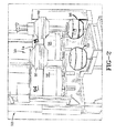
- tire apparatus 50 may include a tire curing press 52 that exerts pressure to hold upper and lower mold halves 54, 56 together during the shaping and vulcanization processes.
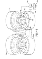
- FIGURE 3 is a schematic representation showing the upper mold halves 54 lifted up to reveal the bladders 58 used to shape the tires 30. Because the operation of tire curing presses and tire molds is well known to those of skill in the art, further details will not be provided except as noted below.
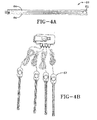
- FIGURE 4A shows a pressure sensor 60 that may be used in this invention.
- the pressure senor was used to directly measure the pressure data during a tire shaping and curing process.
- directly it is meant that the data obtained is from real experimental measurement, not an inference from other data, such as data inferred indirectly from temperature measurement.
- a tire engineer may accurately measure the contact pressures during the whole shaping process and/or the whole curing process both: (1) between the bladder 58 and green tire 30; and/or, (2) between the green tire 30 and mold halves 54, 56.
- Other possible applications include, for example without limitation, to diagnose and correct shaping problems; to detect non-symmetric shaping variation between the top and bottom mold halves and along the circumference of the mold; to validate the simulation results from running finite element analysis (FEA) on of press-shaping modeling; and to diagnose other curing press issues.
- FEA finite element analysis
- the pressure sensor 60 may include a layer of electrical resistive ink 62 sandwiched between thin circular conducting plates 64.
- the electrical resistance between the plates 64 may decrease proportionally to the increase of the squeezing force, and thus proportionally to the pressure.
- a pressure sensor 60 may be of any size and shape chosen with the sound judgment of a person of skill in the art. In one embodiment, the pressure sensor 60 may be about 2 inches long.
- a data logging system 66 Economicical Load and Force (ELF) system with 16 channels for recording data of up to 16 pressure sensors
- ELF Economic Load and Force
- USB universal serial bus
- a special fixture 68 designed for high temperature may connect the sensor 60 and handle 67. If the handles 67 can withstand the actual temperatures encountered, such fixture 68 will not be necessary.
- the pressure sensor 60 can be calibrated in standard press with known pressure characteristics for pressures up to 400 psi and temperatures up to 200 Celsius. In testing, in order to verify the pressure sensor 60 results, thermocouples were used.
- Common curing conditions include temperatures up to 198 degrees Celsius and pressures that range between 8 pounds per square inch (PSI) in pre-shaping and 400 PSI in the curing phase.
- PSI pounds per square inch
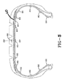
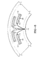
- 16 pressure sensors 60 are shown mounted on tire 10: 14 out of the 16 pressure sensors 60 on the inner liner 22 surface spaced bead-to-bead 14 and 2 pressure sensor 60 spaced within the tire 10, between the overlay 108 and belt 26.
- Small gum strips 74 may be used to fix the sensors 60 to the green tire 30 and Mylar film 72 may be used to protect the sensors 60 from curing into the green tire 30.
- the pressure data measured by the pressure sensors 60 can be communicated out of the tire mold in any manner chosen with the sound judgment of a person of skill in the art.
- the pressure data can be communicated wirelessly.
- a signal wire 76 of any type and size chosen with the sound judgment of a person of skill in the art can be used to communicate the pressure data.
- Two non-limiting examples of signal wire 76 are: Teflon coated copper wire and 28-gauge copper wire with polyimide insulation.
- the signal wires 76 were electrically connected to sensor pins.
- the signal wires 76 from all the sensors 60 may then be twisted into a cable.
- the tread 28 may be peeled back to allow placement of sensors 60 on top of overlay 108.
- Two sensors 60 may be mounted between the tread 28 and belt 26 if the tire has no overlay: one at the centerline, and the other at the belt edge, as shown in FIGURES 5 and 7A .
- the approximate timing of the tire loading sequence may be about 100 seconds to 120 seconds.
- the tire apparatus 50 may include: a tire mold 54, 56; a bladder 58; a tire curing press 52; and, one or more pressure sensors 60.
- Each pressure sensor 60 may be positioned: (1) between the green tire 30 and the bladder 58; or, (2) between the green tire 30 and the tire mold 54, 56. In either case, the pressure sensor 60 directly measures the pressure unlike the prior art.
- the sensor 60 is an ultra-thin, flexible printed circuit.
- the standard sensor 60 is constructed of two layers of substrate (polyester) film.
- the high-temp model is constructed of two layers of polyimide.
- a conductive material (silver) is applied, followed by a layer of pressure-sensitive ink.
- Adhesive is then used to laminate the two layers of substrate together to form the sensor 60.
- the active sensing area is defined by the silver circle 64 on top of the pressure-sensitive ink 62. Silver extends from the sensing area to the connectors at the other end of the sensor 60, forming the conductive leads.
- a sensor is terminated with male square pins, allowing them to be easily incorporated into a circuit.
- the two outer pins of the connector are active and the center pin is inactive.
- the sensor acts as a force sensing resistor in an electrical circuit. When the force sensor is unloaded, its resistance is very high. When a force is applied to the sensor, this resistance decreases. The resistance can be read by connecting a multimeter to the outer two pins, and then applying a force to the sensing area.
- FIGURE 7C the plot shows both the resistance vs. force vs. and conductance (1/R) vs. force. Note that the conductance curve is linear, and therefore useful in calibration.
- the sensors can be custom-designed to meet the needs of an endless variety of applications and the high-temperature model can measure forces in temperatures up to 200°C.
- the sensors are pliable enough to allow for non-intrusive measurement. They can be attached to many different surfaces of tires, and can be combined with plastic or metal films for increased stiffness or for added protection from abrasion.
- the pressure sensors 60 may be used to communicate the pressure they measure during a time period to a data log device 66 that provides corresponding data that can be used to form a graph showing the force exerted on the green tire 30 versus time.
- the pressure sensor can be mounted to the green tire.
- the pressure sensors of this invention not only permit the accurate measuring of contact sequence, but also have applications in absolute pressure measurement.
- the pressure sensors may also be used: to compare shaping profiles and pressures; for different bladders shaping the same tire; new versus used bladders; different shaping strategies; measurements of top versus bottom; trapped air versus no trapped air; tires with lights problems; and, for measurements around a tire. Further, one can measure shaping pressure inside tire, such as between components, for example, belt and tread; or under tread lugs versus under grooves.
- a pressure sensor 60 To use a pressure sensor 60 properly, it may be necessary to: condition the sensor regularly; recalibrate it if it has not been used for an extended period of time; account for the hysteresis; and, flatten the contact surface of the sensor by using a rigid "puck" or disk (not shown in present invention), that distributes the force over the sensing area.
- the puck must be no larger than the active sensing surface.
- the sensor 60 may be sandwiched between two rubber mats, which may be covered with Teflon to prevent sticking. Each mat may be ten inches on each side, in one embodiment, to allow for easy conversion between squeezing force and pressure.
- a programmable press may be used to apply a force to the sensor at stable room temperatures and other operating temperatures such as 100 degrees Celsius or 150 degrees Celsius.
- all sensors may be preconditioned to at least 350 psi. Then, the sensors may be paired to corresponding handles 67 so that a given sensor will always use the same handle 67. If pucks 128 are used, the pucks 128 may be used with the sensor 60 during calibration. After calibration, the sensors 60 may be used.
- At least one pressure sensor 60 is used to directly measure the pressure between the green tire and the bladder. In another embodiment, at least one pressure sensor 60 is used to directly measure the pressure between the green tire and the tire mold. In one specific embodiment, the pressure sensors 60 can be placed between the inner surface of the green tire juxtaposed to one of the pair of beads. In another specific embodiment, the pressure sensors 60 can be mounted to the inner surface of the green tire juxtaposed to the crown section. In yet other embodiments, pressure sensors 60 can be mounted to the outer surface of the green tire such as to the tread of the green tire at various circumferential locations.
- the communication wires are extended therefrom.
- the communication wires extend outside the tire mold and can be connected to other devices (so the pressure data can be sent there).
- the measured data during a time period can be communicated by the pressure sensors 60 to a data log device.
- the data log device provides corresponding data that can be used to form a graph showing the force exerted on the associated green tire versus time. After the tire is cured, the tire mold can be opened to permit removal of the cured tire.
- pressure sensors have been mounted to an inner surface of the green tire and/or an outer surface of the green tire
- mount a pressure sensor to an outer surface of the bladder to directly measure the pressure between the tire and the bladder
- mount a pressure sensor to an inner surface of the tire mold to directly measure the pressure between the tire and the tire mold.
- the manner in which pressure sensors are mounted to the bladder and/or the tire mold can be any chosen with the sound judgment of a person of skill in the art.
Abstract
An apparatus comprising a tire mold that is closable about an associated green tire (30) and at least one first pressure sensor (60) is disclosed The at least one first pressure sensor (60) is positioned such that it is located between the associated green tire (30) and an associated bladder (58) and usable to directly measure the pressure between the associated green tire (30) and the associated bladder (58) while the associated bladder is expanded to shape the associated green tire against a closed tire mold; and/or located between the associated green tire (30) and the tire mold and usable to directly measure the pressure between the associated green tire (30) and the tire mold while an associated tire curing press vulcanizes the associated green tire within the tire mold into an associated cured tire (10). Also, methods of measuring pressure using this apparatus are disclosed.
Description
- This invention generally relates to methods and apparatuses concerning the shaping of tires in tire molds and more specifically to methods and apparatuses concerning the direct measurement of pressure on a tire going through a shaping process and/or a curing process.
- It is long known to manufacture a tire using the following method: construct a green (uncured) tire on a tire building drum; insert the green tire into a tire mold; close the tire mold around the green tire; shape the green tire against the tire mold with a bladder; vulcanize the green tire into a cured tire with a curing press; and, open the mold and remove the cured tire.
- Understanding and controlling the tire shaping process is important to ensure proper tire component positions and gauges, and consequently tire uniformity and performance. One important aspect of the shaping process is the specific pressure exerted on the tire by the bladder and by the mold. Given the relatively high pressures and temperatures that are used in shaping a tire, it has proven to be very difficult to determine with accuracy the pressures involved. Similarly, it has proven to be very difficult to determine with accuracy the pressures involved in curing a tire. It is only known to use indirect methods to determine these pressures - such as using thermocouples where a sudden temperature jump indicates the onset of contact.
- What is needed is a way to directly determine the pressures exerted on a tire during the shaping process and/or during the curing process.
- The invention relates to an apparatus in accordance with
claim 1 and to methods in accordance with claims 8 or 9. - Dependent claims refer to preferred embodiments of the invention.
- According to one embodiment of this invention, an apparatus may comprise: a tire mold that is closable about an associated green tire; and, a first pressure sensor that is one of: positioned between the associated green tire and an associated bladder; and, used to directly measure the pressure between the associated green tire and the associated bladder while the associated bladder is expanded to shape the associated green tire against the closed tire mold; and positioned between the associated green tire and the tire mold; and used to directly measure the pressure between the associated green tire and the tire mold while an associated tire curing press vulcanizes the associated green tire within the tire mold into an associated cured tire.
- According to another embodiment of this invention, a method may comprise the steps of: (A) providing a bladder, a tire mold and, a green tire; (B) mounting a first pressure sensor to one of an inner surface of the green tire and an outer surface of the bladder; (C) inserting the green tire into the tire mold and closing the tire mold; (D) shaping the green tire by expanding the bladder within the green tire against the closed tire mold; and (E) using the first pressure sensor to directly measure the pressure between the green tire and the bladder during step (D).
- According to yet another embodiment of this invention, a method may comprise the steps of: (A) providing a tire curing press, a tire mold and, a green tire; (B) mounting a first pressure sensor to one of an outer surface of the green tire and an inner surface of the tire mold; (C) inserting the green tire into the tire mold and closing the tire mold; (D) vulcanizing the green tire within the tire mold into a cured tire; and (E) using the first pressure sensor to directly measure the pressure between the green tire and the tire mold during step (D).
- One advantage of present invention is the contact sequence measurement method can be used to diagnose and correct press shaping problems, detect non-symmetric shaping, both top vs. bottom and circumferential variations, validate FEA press-shaping modeling work, and diagnose other curing press issues such as lights (that is, areas of incomplete mold filing).
- One advantage of present invention is the method can also be used to measure absolute pressures inside the tire, which may be useful in developing an understanding of tire blow point. The measurement can be done during the entire shaping and/or curing process rather than only before the mold is closed.
- One advantage of present invention is the method measures the contact pressure between the bladder/green tire and green tire/mold directly, rather than using an indirect method such as temperature which can only indicate contact.
- Other benefits and advantages of the invention will become apparent to those skilled in the art to which it pertains upon a reading and understanding of the following detailed specification.
- The following definitions are applicable to the present invention.
- "Axial" and "axially" mean lines or directions that are parallel to the axis of rotation of the tire.
- "Carcass" means the tire structure apart from the belt structure, tread, and undertread but including the beads.
- "Radial" and "radially" are used to mean directions radially toward or away from the axis of rotation of the tire.
- "Tread" means an extruded rubber component which, when bonded to a tire casing, includes that portion of the tire that comes into contact with the road when the tire is normally inflated and under normal load.
- The invention may take physical form in certain parts and arrangement of parts, embodiments of which will be described in detail in this specification and illustrated in the accompanying drawings which form a part hereof and wherein:
-
FIGURE 1 is a cross sectional view of a tire. -
FIGURE 2 is a perspective view of a tire curing apparatus. -
FIGURE 3 is a perspective schematic view of a tire curing apparatus with bladders visible. -
FIGURE 4A is a perspective view of a High-Temperature pressure sensor. -
FIGURE 4B is a perspective view of a multi-handle system with handles connected to a USB hub. -
FIGURE 4C is a software interface showing the force variation measured with the pressure sensor. -
FIGURE 5 shows the locations of the pressure sensors and thermocouples with respect to a tire in one embodiment. -
FIGURE 6 shows a perspective view of pressure sensors mounted to a tire sidewall. -
FIGURE 7A shows a perspective view of the pressure sensors mounted to a tire between the tread and belt. -
FIGURE 7B shows a perspective view of the pressure sensor. -
FIGURE 7C shows both the resistance vs. force and conductance (1/R) vs. force. -
FIGURE 8 shows a plot of force versus time results when using pressure sensors. - Referring now to the drawings wherein the showings are for purposes of illustrating embodiments of the invention and wherein like reference numerals are understood to refer to like components,
FIGURE 1 , shows atire 10 that may use at least onepressure sensor 60, shown inFIGURE 4A , according to this invention. Thetire 10 may be of any type and size chosen with the sound judgment of a person of skill in the art including, for some non-limiting examples, a truck tire, a light truck tire, an airplane tire or a passenger tire. Thetire 10 may have acarcass 12 that may include a pair ofannular beads more plies 16 that may extend from around thebeads sidewall rubber portions carcass 12 may define acrown section 18 and a pair ofsidewalls carcass 12 such as aninner liner 22, abelt package 26 and atread 28. - With reference now to
FIGURE 2 , thetire 10 may be first formed as a green (uncured) tire 30 (four such green tires are shown) as is well known in the art. Thegreen tire 30 may then be taken to atire apparatus 50 where it may be shaped and vulcanized (cured). Thetire apparatus 50 can be of any type and size chosen with the sound judgment of a person of skill in the art. For the embodiment shown inFIGURE 2 ,tire apparatus 50 may include a tire curingpress 52 that exerts pressure to hold upper andlower mold halves FIGURE 3 is a schematic representation showing theupper mold halves 54 lifted up to reveal thebladders 58 used to shape thetires 30. Because the operation of tire curing presses and tire molds is well known to those of skill in the art, further details will not be provided except as noted below. -
FIGURE 4A shows apressure sensor 60 that may be used in this invention. The pressure senor was used to directly measure the pressure data during a tire shaping and curing process. Here by "directly" it is meant that the data obtained is from real experimental measurement, not an inference from other data, such as data inferred indirectly from temperature measurement. Using thepressure sensors 60 of this invention, a tire engineer may accurately measure the contact pressures during the whole shaping process and/or the whole curing process both: (1) between thebladder 58 andgreen tire 30; and/or, (2) between thegreen tire 30 andmold halves - With reference now to
FIGURES 3-5 , thepressure sensor 60 may include a layer of electricalresistive ink 62 sandwiched between thincircular conducting plates 64. The electrical resistance between theplates 64 may decrease proportionally to the increase of the squeezing force, and thus proportionally to the pressure. Apressure sensor 60 may be of any size and shape chosen with the sound judgment of a person of skill in the art. In one embodiment, thepressure sensor 60 may be about 2 inches long. A data logging system 66 (Economical Load and Force (ELF) system with 16 channels for recording data of up to 16 pressure sensors) may be used to record the pressure data. There is also a handle system withhandles 67 connected to universal serial bus (USB) hub. Aspecial fixture 68 designed for high temperature may connect thesensor 60 and handle 67. If thehandles 67 can withstand the actual temperatures encountered,such fixture 68 will not be necessary. Thepressure sensor 60 can be calibrated in standard press with known pressure characteristics for pressures up to 400 psi and temperatures up to 200 Celsius. In testing, in order to verify thepressure sensor 60 results, thermocouples were used. - Common curing conditions include temperatures up to 198 degrees Celsius and pressures that range between 8 pounds per square inch (PSI) in pre-shaping and 400 PSI in the curing phase. With reference now to
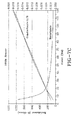
FIGURES 5-7 , 16pressure sensors 60 are shown mounted on tire 10: 14 out of the 16pressure sensors 60 on theinner liner 22 surface spaced bead-to-bead 14 and 2pressure sensor 60 spaced within thetire 10, between theoverlay 108 andbelt 26. Small gum strips 74 may be used to fix thesensors 60 to thegreen tire 30 andMylar film 72 may be used to protect thesensors 60 from curing into thegreen tire 30. The pressure data measured by thepressure sensors 60 can be communicated out of the tire mold in any manner chosen with the sound judgment of a person of skill in the art. In one embodiment, not shown, the pressure data can be communicated wirelessly. In another embodiment, asignal wire 76 of any type and size chosen with the sound judgment of a person of skill in the art can be used to communicate the pressure data. Two non-limiting examples ofsignal wire 76 are: Teflon coated copper wire and 28-gauge copper wire with polyimide insulation. Thesignal wires 76 were electrically connected to sensor pins. Thesignal wires 76 from all thesensors 60 may then be twisted into a cable. Thetread 28 may be peeled back to allow placement ofsensors 60 on top ofoverlay 108. Twosensors 60 may be mounted between thetread 28 andbelt 26 if the tire has no overlay: one at the centerline, and the other at the belt edge, as shown inFIGURES 5 and7A . The approximate timing of the tire loading sequence may be about 100 seconds to 120 seconds. Test results indicated that thepressure sensors 60 can qualitatively detect different cure pressures, as shown inFIGURES 8 . Test results also show that thepressure sensors 60 can survive cure environment and yield significant data regarding shaping contact and contact pressures. - With reference now to
FIGURE 2-3 , thetire apparatus 50 may include: atire mold bladder 58; atire curing press 52; and, one ormore pressure sensors 60. Eachpressure sensor 60 may be positioned: (1) between thegreen tire 30 and thebladder 58; or, (2) between thegreen tire 30 and thetire mold pressure sensor 60 directly measures the pressure unlike the prior art. - With reference now to
FIGURES 6 and7A-7C . Thesensor 60 is an ultra-thin, flexible printed circuit. Thestandard sensor 60 is constructed of two layers of substrate (polyester) film. The high-temp model is constructed of two layers of polyimide. On each layer, a conductive material (silver) is applied, followed by a layer of pressure-sensitive ink. Adhesive is then used to laminate the two layers of substrate together to form thesensor 60. The active sensing area is defined by thesilver circle 64 on top of the pressure-sensitive ink 62. Silver extends from the sensing area to the connectors at the other end of thesensor 60, forming the conductive leads. A sensor is terminated with male square pins, allowing them to be easily incorporated into a circuit. The two outer pins of the connector are active and the center pin is inactive. The sensor acts as a force sensing resistor in an electrical circuit. When the force sensor is unloaded, its resistance is very high. When a force is applied to the sensor, this resistance decreases. The resistance can be read by connecting a multimeter to the outer two pins, and then applying a force to the sensing area. InFIGURE 7C , the plot shows both the resistance vs. force vs. and conductance (1/R) vs. force. Note that the conductance curve is linear, and therefore useful in calibration. - Depending on the needs of the application, users can trim the sensors to the length of their choosing. In the example application, the sensor is trimmed to lengths of 5.08 cm. In addition, the sensors can be custom-designed to meet the needs of an endless variety of applications and the high-temperature model can measure forces in temperatures up to 200°C. The sensors are pliable enough to allow for non-intrusive measurement. They can be attached to many different surfaces of tires, and can be combined with plastic or metal films for increased stiffness or for added protection from abrasion.
- With reference now to
FIGURES 8 , thepressure sensors 60 may be used to communicate the pressure they measure during a time period to adata log device 66 that provides corresponding data that can be used to form a graph showing the force exerted on thegreen tire 30 versus time. The pressure sensor can be mounted to the green tire. - The pressure sensors of this invention not only permit the accurate measuring of contact sequence, but also have applications in absolute pressure measurement. The pressure sensors may also be used: to compare shaping profiles and pressures; for different bladders shaping the same tire; new versus used bladders; different shaping strategies; measurements of top versus bottom; trapped air versus no trapped air; tires with lights problems; and, for measurements around a tire. Further, one can measure shaping pressure inside tire, such as between components, for example, belt and tread; or under tread lugs versus under grooves.
- To use a
pressure sensor 60 properly, it may be necessary to: condition the sensor regularly; recalibrate it if it has not been used for an extended period of time; account for the hysteresis; and, flatten the contact surface of the sensor by using a rigid "puck" or disk (not shown in present invention), that distributes the force over the sensing area. The puck must be no larger than the active sensing surface. To calibrate thesensor 60, thesensor 60 may be sandwiched between two rubber mats, which may be covered with Teflon to prevent sticking. Each mat may be ten inches on each side, in one embodiment, to allow for easy conversion between squeezing force and pressure. A programmable press may be used to apply a force to the sensor at stable room temperatures and other operating temperatures such as 100 degrees Celsius or 150 degrees Celsius. To calibrate a group of sensors in one embodiment, all sensors may be preconditioned to at least 350 psi. Then, the sensors may be paired tocorresponding handles 67 so that a given sensor will always use thesame handle 67. If pucks 128 are used, the pucks 128 may be used with thesensor 60 during calibration. After calibration, thesensors 60 may be used. - First, a decision is made as to the location and number of
pressures sensors 60 to be used. In one embodiment, at least onepressure sensor 60 is used to directly measure the pressure between the green tire and the bladder. In another embodiment, at least onepressure sensor 60 is used to directly measure the pressure between the green tire and the tire mold. In one specific embodiment, thepressure sensors 60 can be placed between the inner surface of the green tire juxtaposed to one of the pair of beads. In another specific embodiment, thepressure sensors 60 can be mounted to the inner surface of the green tire juxtaposed to the crown section. In yet other embodiments,pressure sensors 60 can be mounted to the outer surface of the green tire such as to the tread of the green tire at various circumferential locations. - As the
pressure sensors 60 are mounted to thegreen tire 30 the communication wires are extended therefrom. As thegreen tire 30 is inserted into the tire mold, the communication wires extend outside the tire mold and can be connected to other devices (so the pressure data can be sent there). The measured data during a time period can be communicated by thepressure sensors 60 to a data log device. The data log device provides corresponding data that can be used to form a graph showing the force exerted on the associated green tire versus time. After the tire is cured, the tire mold can be opened to permit removal of the cured tire. - It should be noted that while thus far the pressure sensors have been mounted to an inner surface of the green tire and/or an outer surface of the green tire, it is also contemplated to mount a pressure sensor to an outer surface of the bladder (to directly measure the pressure between the tire and the bladder) and/or to mount a pressure sensor to an inner surface of the tire mold (to directly measure the pressure between the tire and the tire mold). The manner in which pressure sensors are mounted to the bladder and/or the tire mold can be any chosen with the sound judgment of a person of skill in the art.
Claims (15)
- An apparatus comprising a tire mold that is closable about an associated green tire (30), and at least one first pressure sensor (60) that is positioned such that:(i) it is located between the associated green tire (30) and an associated bladder (58) and usable to directly measure the pressure between the associated green tire (30) and the associated bladder (58) while the associated bladder is expanded to shape the associated green tire against a closed tire mold; and/or(ii) located between the associated green tire (30) and the tire mold and usable to directly measure the pressure between the associated green tire (30) and the tire mold while an associated tire curing press vulcanizes the associated green tire within the tire mold into an associated cured tire (10).
- The apparatus of claim 1 wherein the associated green tire (10) comprises a pair of beads (14) and a crown section (18) and wherein the at least one first pressure sensor (60) is positioned such that it is located between the associated green tire (10) and the associated bladder (58) juxtaposed to one of the beads (14).
- The apparatus of claim 1 or 2 wherein the apparatus (50) further comprises at least one second pressure sensor that is positioned such that it is located between the associated green tire (30) and the associated bladder (58) juxtaposed to the crown section (18) and usable to directly measure the pressure between the associated green tire (30) and the associated bladder (58) while the associated bladder (58) is expanded to shape the associated green tire (10) against a closed tire mold.
- The apparatus of at least one of the previous claims wherein the associated green tire (30) comprises a tread (28) and the at least one first pressure sensor (60) is positioned such that it is located between the associated green tire (30) and the tire mold at a first circumferential location and usable to directly measure the pressure between the associated green tire (30) and the tire mold while the associated tire curing press vulcanizes the associated green tire within the tire mold into an associated cured tire (10).
- The apparatus of at least one of the previous claims wherein the apparatus (50) further comprises at least one second pressure sensor that is positioned such that it is located between the associated green tire (30) and the tire mold at a second circumferential location and usable to directly measure the pressure between the associated green tire (30) and the tire mold while the associated tire curing press vulcanizes the associated green tire (30) within the tire mold into an associated cured tire (10).
- The apparatus of at least one of the previous claims wherein the at least one first pressure sensor (60) is configured to communicate the pressure it measures during a time period to a device that provides corresponding data that can be used to form a graph showing the force exerted on the associated green tire (10) versus time.
- The apparatus of at least one of the previous claims wherein the at least one first pressure sensor (60) is configured to operates at pressures at least up to 2.758 MPa and at temperatures at least up to 200 degrees Celsius.
- A method comprising the steps of:(A) providing a bladder (58), a tire mold and, a green tire (30);(B) mounting at least one first pressure sensor (60) to one of an inner surface of the green tire (30) an outer surface of the bladder (58);(C) inserting the green tire into the tire mold and closing the tire mold;(D) shaping the green tire (30) by expanding the bladder (58) within the green tire (30) against a closed tire mold; and(E) using the at least one first pressure sensor (60) to directly measure the pressure between the green tire (30) and the bladder (58) during step (D).
- A method comprising the steps of:(A) providing a tire curing press, a tire mold and a green tire (30);(B) mounting at least one first pressure sensor (60) to one of an outer surface of the green tire (30) and an inner surface of the tire mold;(C) inserting the green tire (30) into the tire mold and closing the tire mold;(D) vulcanizing the green tire within the tire mold into a cured tire; and(E) using the at least one first pressure sensor to directly measure the pressure between the green tire (30) and the tire mold during step (D).
- The method of claim 8 or 9 wherein step (E) comprises the step of:communicating a plurality of pressures measured by the at least one first pressure sensor (60) during a time period to a device that provides corresponding data that can be used to form a graph showing the force exerted on the associated green tire (30) versus time.
- The method of claim 8 or 9 wherein:step (B) comprises the step of attaching a communication wire (76) to the at least one first pressure sensor (60); andstep (C) comprises the step of extending the communication wire (76) outside the tire mold.
- The method of claim 8 wherein:step (A) comprises the step of: providing the green tire (30) with a pair of beads (14) and a crown section (18);step (B) comprises the step of: mounting the at least one first pressure sensor (60) to the one of the inner surface of the green tire (30) and the outer surface of the bladder (58) juxtaposed to one of the pair of beads (14);before step (C) the method comprises the step of: mounting at least one second pressure sensor to one of the inner surface of the green tire (30) and the outer surface of the bladder (58) juxtaposed to the crown section (18); andstep (E) comprises the step of: using the second pressure sensor to directly measure the pressure between the green tire (30) and the bladder (58) during step (D).
- The method of claim 8 or 12 wherein:step (A) comprises the step of: providing a tire curing press;step (F) comprises vulcanizing the green tire (30) within the tire mold into a cured tire (10); andstep (E) comprises using the at least one first pressure sensor (60) to directly measure the pressure between the green tire (30) and the bladder (58) during step (F); and wherein the method optionally further comprises the steps of:(G) opening the tire mold;(H) removing the cured tire (10) from the tire mold; and,(I) removing the at least one first pressure sensor (60).
- The method of claim 8, 12 or 13 wherein:step (A) comprises the step of: providing the green tire with a pair of beads, a crown section and a tread;step (B) comprises the steps of: mounting the first pressure sensor to the one of the inner surface of the green tire and the outer surface of the bladder juxtaposed to one of the pair of beads; and mounting the second pressure sensor to the one of the outer surface of the green tire and the inner surface of the tire mold at first circumferential tread location;before step (C) the method comprises the steps of: mounting a third pressure sensor to one of the inner surface of the green tire and an outer surface of the bladder juxtaposed to the crown section; and mounting a fourth pressure sensor to one of an outer surface of the green tire and an inner surface of the tire mold at a second circumferential tread location;step (E) comprises the steps of: using the third pressure sensor to directly measure the pressure between the green tire and the bladder during steps (D) and (F); using the fourth pressure sensor to directly measure the pressure between the green tire and the tire mold during steps (D) and (F); and communicating a plurality of pressures measured by each of the first, second, third and fourth pressure sensors during a time period to a device that provides corresponding data that can be used to form a graph showing the force exerted on the associated green tire versus time; and, optionally,step (I) comprises the step of: removing the third and fourth pressure sensors.
- The method of claim 9, 10 or 11 wherein:step (A) comprises the step of: providing the green tire with a tread;step (B) comprises the step of: mounting the at least one first pressure sensor to the one of the outer surface of the green tire and the inner surface of the tire mold at a first circumferential tread location;before step (C) the method comprises the step of: mounting at least one second pressure sensor to one of an outer surface of the green tire and an inner surface of the tire mold at a second circumferential tread location; and,step (F) comprises the step of: using the at least one second pressure sensor to directly measure the pressure between the green tire and the tire mold during step (D).
Applications Claiming Priority (1)
| Application Number | Priority Date | Filing Date | Title |
|---|---|---|---|
| US12/956,676 US9656434B2 (en) | 2010-11-30 | 2010-11-30 | Measuring tire pressure in a tire mold |
Publications (1)
| Publication Number | Publication Date |
|---|---|
| EP2457721A1 true EP2457721A1 (en) | 2012-05-30 |
Family
ID=45002830
Family Applications (1)
| Application Number | Title | Priority Date | Filing Date |
|---|---|---|---|
| EP11190888A Withdrawn EP2457721A1 (en) | 2010-11-30 | 2011-11-28 | Measuring tire pressure in a tire mold |
Country Status (4)
| Country | Link |
|---|---|
| US (2) | US9656434B2 (en) |
| EP (1) | EP2457721A1 (en) |
| CN (1) | CN102476462B (en) |
| BR (1) | BRPI1105601A2 (en) |
Cited By (1)
| Publication number | Priority date | Publication date | Assignee | Title |
|---|---|---|---|---|
| CN103954507A (en) * | 2014-05-12 | 2014-07-30 | 山东豪迈机械科技股份有限公司 | Pressure testing device for tire mold |
Families Citing this family (4)
| Publication number | Priority date | Publication date | Assignee | Title |
|---|---|---|---|---|
| CN105034716B (en) * | 2015-07-09 | 2017-05-24 | 特拓(青岛)轮胎技术有限公司 | Tyre internal temperature and pressure detection device and detection method |
| EP3192648B1 (en) * | 2016-01-14 | 2019-03-06 | Compagnie Générale des Etablissements Michelin | Regulating temperature during tire vulcanization |
| DE102016123795A1 (en) * | 2016-12-08 | 2018-06-14 | Gottfried Wilhelm Leibniz Universität Hannover | Process for applying an electrical microstructure and elastomer structure, fiber composite component and tires |
| US11904563B1 (en) | 2020-05-12 | 2024-02-20 | Teddy Lee Gore | System, apparatus and method for programmable logic control of pressure in a tire curing press bladder |
Citations (9)
| Publication number | Priority date | Publication date | Assignee | Title |
|---|---|---|---|---|
| US4422987A (en) * | 1981-07-24 | 1983-12-27 | Sumitomo Rubber Industries, Ltd. | Method for vulcanizing an elastomer |
| US4502857A (en) * | 1983-04-04 | 1985-03-05 | The Goodyear Tire & Rubber Company | Green tire-to-mold contact time detection, analysis, and control |
| US4763534A (en) * | 1985-01-31 | 1988-08-16 | Robert G. Fulks | Pressure sensing device |
| US4781561A (en) * | 1987-02-16 | 1988-11-01 | Consiglio Nazionale Delle Ricerche | Apparatus for controlling the cross-linking of elastomers in a mould |
| EP1000727A1 (en) * | 1998-11-16 | 2000-05-17 | General Electric Company | Method and apparatus for detecting pressure in a compression mould |
| EP1785706A1 (en) * | 2005-11-15 | 2007-05-16 | IEE INTERNATIONAL ELECTRONICS & ENGINEERING S.A. | Method for producing an electric circuit on a flexible substrate |
| JP2007298428A (en) * | 2006-05-01 | 2007-11-15 | Yokohama Rubber Co Ltd:The | Pressure-sensitive sensor for pressure measurement of plastic material |
| JP2007301899A (en) * | 2006-05-12 | 2007-11-22 | Yokohama Rubber Co Ltd:The | Tire vulcanizing method |
| US20090324763A1 (en) * | 2008-06-26 | 2009-12-31 | Michelin Recherche Et Technique S.A. | Pressure Measurement Device and Mould for Vulcanizing Rubber for Tires |
Family Cites Families (14)
| Publication number | Priority date | Publication date | Assignee | Title |
|---|---|---|---|---|
| US3096541A (en) | 1958-09-11 | 1963-07-09 | Goodyear Tire & Rubber | Apparatus for molding a valve receiving aperture in a tire |
| US4115046A (en) | 1977-09-22 | 1978-09-19 | Mcneil Corporation | Probe injection system for a tire curing process |
| US4625101A (en) | 1984-02-27 | 1986-11-25 | The Goodyear Tire & Rubber Company | Bar code configuration and method of molding |
| US4597929A (en) * | 1984-11-23 | 1986-07-01 | The B. F. Goodrich Company | Method for ventless tire molding and tire resulting therefrom |
| US5256348A (en) | 1991-06-13 | 1993-10-26 | Waller Michael V | Tire shaping pressure control system and method |
| US5500065A (en) | 1994-06-03 | 1996-03-19 | Bridgestone/Firestone, Inc. | Method for embedding a monitoring device within a tire during manufacture |
| US6951143B1 (en) | 2000-11-28 | 2005-10-04 | Michelin Recherche Et Technique S.A. | Three-axis sensor assembly for use in an elastomeric material |
| DE60229028D1 (en) | 2001-07-10 | 2008-11-06 | Michelin Soc Tech | A measuring device containing tires |
| US7104298B2 (en) | 2003-12-22 | 2006-09-12 | The Goodyear Tire & Rubber Company | Tire having antenna attached to elastic fiber textile strip and method of mounting antenna assembly to tire |
| JP4573831B2 (en) | 2004-03-02 | 2010-11-04 | 株式会社ブリヂストン | Electronic device fixing system for pneumatic tire, pneumatic tire and electronic device housing apparatus |
| DE102005024215A1 (en) * | 2004-06-03 | 2005-12-22 | Denso Corp., Kariya | pressure sensor |
| CN100585352C (en) * | 2007-11-23 | 2010-01-27 | 清华大学 | Array type ultra-thin submissive force sensor and preparation method thereof |
| US20090151829A1 (en) * | 2007-12-18 | 2009-06-18 | Robert Edward Lionetti | Tire with integral sensor mount |
| US20100220065A1 (en) * | 2009-02-27 | 2010-09-02 | Research In Motion Limited | Touch-sensitive display including a force-sensor and portable electronic device including same |
-
2010
- 2010-11-30 US US12/956,676 patent/US9656434B2/en not_active Expired - Fee Related
-
2011
- 2011-11-18 BR BRPI1105601-0A patent/BRPI1105601A2/en not_active IP Right Cessation
- 2011-11-28 EP EP11190888A patent/EP2457721A1/en not_active Withdrawn
- 2011-11-30 CN CN201110389501.XA patent/CN102476462B/en not_active Expired - Fee Related
-
2017
- 2017-04-14 US US15/487,903 patent/US10022928B2/en active Active
Patent Citations (9)
| Publication number | Priority date | Publication date | Assignee | Title |
|---|---|---|---|---|
| US4422987A (en) * | 1981-07-24 | 1983-12-27 | Sumitomo Rubber Industries, Ltd. | Method for vulcanizing an elastomer |
| US4502857A (en) * | 1983-04-04 | 1985-03-05 | The Goodyear Tire & Rubber Company | Green tire-to-mold contact time detection, analysis, and control |
| US4763534A (en) * | 1985-01-31 | 1988-08-16 | Robert G. Fulks | Pressure sensing device |
| US4781561A (en) * | 1987-02-16 | 1988-11-01 | Consiglio Nazionale Delle Ricerche | Apparatus for controlling the cross-linking of elastomers in a mould |
| EP1000727A1 (en) * | 1998-11-16 | 2000-05-17 | General Electric Company | Method and apparatus for detecting pressure in a compression mould |
| EP1785706A1 (en) * | 2005-11-15 | 2007-05-16 | IEE INTERNATIONAL ELECTRONICS & ENGINEERING S.A. | Method for producing an electric circuit on a flexible substrate |
| JP2007298428A (en) * | 2006-05-01 | 2007-11-15 | Yokohama Rubber Co Ltd:The | Pressure-sensitive sensor for pressure measurement of plastic material |
| JP2007301899A (en) * | 2006-05-12 | 2007-11-22 | Yokohama Rubber Co Ltd:The | Tire vulcanizing method |
| US20090324763A1 (en) * | 2008-06-26 | 2009-12-31 | Michelin Recherche Et Technique S.A. | Pressure Measurement Device and Mould for Vulcanizing Rubber for Tires |
Cited By (2)
| Publication number | Priority date | Publication date | Assignee | Title |
|---|---|---|---|---|
| CN103954507A (en) * | 2014-05-12 | 2014-07-30 | 山东豪迈机械科技股份有限公司 | Pressure testing device for tire mold |
| CN103954507B (en) * | 2014-05-12 | 2016-03-23 | 山东豪迈机械科技股份有限公司 | Tire-mold pressure test device |
Also Published As
| Publication number | Publication date |
|---|---|
| BRPI1105601A2 (en) | 2013-03-19 |
| US9656434B2 (en) | 2017-05-23 |
| CN102476462A (en) | 2012-05-30 |
| CN102476462B (en) | 2014-12-17 |
| US20170217114A1 (en) | 2017-08-03 |
| US20120133086A1 (en) | 2012-05-31 |
| US10022928B2 (en) | 2018-07-17 |
Similar Documents
| Publication | Publication Date | Title |
|---|---|---|
| US10022928B2 (en) | Measuring tire pressure in a tire mold | |
| CN1953881B (en) | Wiring and method for instrumenting a tyre or an antivibration hinge or a safety support for a vehicle contact with ground | |
| US10792960B2 (en) | Article with electronic component inclusion | |
| JP5580903B2 (en) | Method for controlling product volume in a fixed volume mold | |
| US3662596A (en) | Device for measuring stress in metal tire cords | |
| EP3628479B1 (en) | Tire with printed strain sensors | |
| JP5056119B2 (en) | Method for measuring deformation behavior of tire reinforcement layer | |
| JP4816232B2 (en) | Tire vulcanization method | |
| JP2008249567A (en) | Deformation measuring method for pneumatic tire | |
| JP4853146B2 (en) | Tire vulcanization method | |
| JP4967461B2 (en) | Pressure measurement method for tire components | |
| JP7475136B2 (en) | TIRE BUILDING MOLD AND METHOD FOR MANUFACTURING PNEUMATIC TIRE | |
| US20200156337A1 (en) | Temperature sensor, and method for producing pneumatic tire | |
| US10336141B2 (en) | Tire having static charge dissipation element | |
| JP7429546B2 (en) | Tire molding mold and pneumatic tire manufacturing method | |
| JP7063917B2 (en) | Pneumatic tires | |
| JP6776569B2 (en) | How to measure the amount of deformation of a tire bladder | |
| JP2021104615A (en) | Tire molding die and manufacturing method of pneumatic tire | |
| US9415554B2 (en) | Method of controlling product volume in a fixed volume mold | |
| KR20040009487A (en) | Apparatus for Measuring the Cure Kinetics of Tire Carcass Plies | |
| JP2017100297A (en) | Tire vulcanizing bladder |
Legal Events
| Date | Code | Title | Description |
|---|---|---|---|
| PUAI | Public reference made under article 153(3) epc to a published international application that has entered the european phase |
Free format text: ORIGINAL CODE: 0009012 |
|
| AK | Designated contracting states |
Kind code of ref document: A1 Designated state(s): AL AT BE BG CH CY CZ DE DK EE ES FI FR GB GR HR HU IE IS IT LI LT LU LV MC MK MT NL NO PL PT RO RS SE SI SK SM TR |
|
| AX | Request for extension of the european patent |
Extension state: BA ME |
|
| STAA | Information on the status of an ep patent application or granted ep patent |
Free format text: STATUS: THE APPLICATION IS DEEMED TO BE WITHDRAWN |
|
| 18D | Application deemed to be withdrawn |
Effective date: 20121201 |