EP2458338A1 - Pedometer With Shoe Mounted Sensor And Transmitter - Google Patents
Pedometer With Shoe Mounted Sensor And Transmitter Download PDFInfo
- Publication number
- EP2458338A1 EP2458338A1 EP10192636A EP10192636A EP2458338A1 EP 2458338 A1 EP2458338 A1 EP 2458338A1 EP 10192636 A EP10192636 A EP 10192636A EP 10192636 A EP10192636 A EP 10192636A EP 2458338 A1 EP2458338 A1 EP 2458338A1
- Authority
- EP
- European Patent Office
- Prior art keywords
- pedometer
- shoe
- sensor
- signal generators
- inner margin
- Prior art date
- Legal status (The legal status is an assumption and is not a legal conclusion. Google has not performed a legal analysis and makes no representation as to the accuracy of the status listed.)
- Granted
Links
- 230000005291 magnetic effect Effects 0.000 claims description 9
- 230000005855 radiation Effects 0.000 claims description 8
- 230000005355 Hall effect Effects 0.000 claims description 4
- 230000033001 locomotion Effects 0.000 description 16
- 238000005516 engineering process Methods 0.000 description 9
- 238000000926 separation method Methods 0.000 description 9
- 230000001133 acceleration Effects 0.000 description 4
- 230000037396 body weight Effects 0.000 description 4
- 230000003287 optical effect Effects 0.000 description 4
- 238000004891 communication Methods 0.000 description 3
- 238000012546 transfer Methods 0.000 description 3
- UQSXHKLRYXJYBZ-UHFFFAOYSA-N Iron oxide Chemical compound [Fe]=O UQSXHKLRYXJYBZ-UHFFFAOYSA-N 0.000 description 2
- PXHVJJICTQNCMI-UHFFFAOYSA-N Nickel Chemical compound [Ni] PXHVJJICTQNCMI-UHFFFAOYSA-N 0.000 description 2
- 230000002411 adverse Effects 0.000 description 2
- 238000005452 bending Methods 0.000 description 2
- 239000002131 composite material Substances 0.000 description 2
- 238000001514 detection method Methods 0.000 description 2
- 238000010586 diagram Methods 0.000 description 2
- 230000005021 gait Effects 0.000 description 2
- 239000000696 magnetic material Substances 0.000 description 2
- 238000005259 measurement Methods 0.000 description 2
- 238000000034 method Methods 0.000 description 2
- 230000037081 physical activity Effects 0.000 description 2
- 230000003319 supportive effect Effects 0.000 description 2
- BXNJHAXVSOCGBA-UHFFFAOYSA-N Harmine Chemical compound N1=CC=C2C3=CC=C(OC)C=C3NC2=C1C BXNJHAXVSOCGBA-UHFFFAOYSA-N 0.000 description 1
- 229910001177 Ticonal Inorganic materials 0.000 description 1
- 229910000828 alnico Inorganic materials 0.000 description 1
- 238000004458 analytical method Methods 0.000 description 1
- 238000013459 approach Methods 0.000 description 1
- DSAJWYNOEDNPEQ-UHFFFAOYSA-N barium atom Chemical compound [Ba] DSAJWYNOEDNPEQ-UHFFFAOYSA-N 0.000 description 1
- AYJRCSIUFZENHW-UHFFFAOYSA-L barium carbonate Inorganic materials [Ba+2].[O-]C([O-])=O AYJRCSIUFZENHW-UHFFFAOYSA-L 0.000 description 1
- 230000005540 biological transmission Effects 0.000 description 1
- 230000036772 blood pressure Effects 0.000 description 1
- 239000000919 ceramic Substances 0.000 description 1
- 238000006243 chemical reaction Methods 0.000 description 1
- 239000010941 cobalt Substances 0.000 description 1
- 229910017052 cobalt Inorganic materials 0.000 description 1
- GUTLYIVDDKVIGB-UHFFFAOYSA-N cobalt atom Chemical compound [Co] GUTLYIVDDKVIGB-UHFFFAOYSA-N 0.000 description 1
- 238000010276 construction Methods 0.000 description 1
- 238000011109 contamination Methods 0.000 description 1
- 230000000694 effects Effects 0.000 description 1
- 239000002902 ferrimagnetic material Substances 0.000 description 1
- 239000003302 ferromagnetic material Substances 0.000 description 1
- 230000006870 function Effects 0.000 description 1
- BDAGIHXWWSANSR-NJFSPNSNSA-N hydroxyformaldehyde Chemical compound O[14CH]=O BDAGIHXWWSANSR-NJFSPNSNSA-N 0.000 description 1
- 238000011065 in-situ storage Methods 0.000 description 1
- 230000005381 magnetic domain Effects 0.000 description 1
- 238000004519 manufacturing process Methods 0.000 description 1
- 239000000463 material Substances 0.000 description 1
- 230000007246 mechanism Effects 0.000 description 1
- 238000004377 microelectronic Methods 0.000 description 1
- 238000012986 modification Methods 0.000 description 1
- 230000004048 modification Effects 0.000 description 1
- 238000012806 monitoring device Methods 0.000 description 1
- 238000012544 monitoring process Methods 0.000 description 1
- 238000000465 moulding Methods 0.000 description 1
- 229910052759 nickel Inorganic materials 0.000 description 1
- 230000001144 postural effect Effects 0.000 description 1
- 239000012256 powdered iron Substances 0.000 description 1
- 230000008569 process Effects 0.000 description 1
- 238000012545 processing Methods 0.000 description 1
- 238000010561 standard procedure Methods 0.000 description 1
- 229910000018 strontium carbonate Inorganic materials 0.000 description 1
- 230000004580 weight loss Effects 0.000 description 1
Images


Classifications
-
- G—PHYSICS
- G01—MEASURING; TESTING
- G01C—MEASURING DISTANCES, LEVELS OR BEARINGS; SURVEYING; NAVIGATION; GYROSCOPIC INSTRUMENTS; PHOTOGRAMMETRY OR VIDEOGRAMMETRY
- G01C22/00—Measuring distance traversed on the ground by vehicles, persons, animals or other moving solid bodies, e.g. using odometers, using pedometers
- G01C22/006—Pedometers
-
- A—HUMAN NECESSITIES
- A61—MEDICAL OR VETERINARY SCIENCE; HYGIENE
- A61B—DIAGNOSIS; SURGERY; IDENTIFICATION
- A61B5/00—Measuring for diagnostic purposes; Identification of persons
- A61B5/103—Detecting, measuring or recording devices for testing the shape, pattern, colour, size or movement of the body or parts thereof, for diagnostic purposes
- A61B5/1036—Measuring load distribution, e.g. podologic studies
-
- A—HUMAN NECESSITIES
- A63—SPORTS; GAMES; AMUSEMENTS
- A63B—APPARATUS FOR PHYSICAL TRAINING, GYMNASTICS, SWIMMING, CLIMBING, OR FENCING; BALL GAMES; TRAINING EQUIPMENT
- A63B69/00—Training appliances or apparatus for special sports
- A63B69/0028—Training appliances or apparatus for special sports for running, jogging or speed-walking
-
- A—HUMAN NECESSITIES
- A63—SPORTS; GAMES; AMUSEMENTS
- A63B—APPARATUS FOR PHYSICAL TRAINING, GYMNASTICS, SWIMMING, CLIMBING, OR FENCING; BALL GAMES; TRAINING EQUIPMENT
- A63B2209/00—Characteristics of used materials
- A63B2209/08—Characteristics of used materials magnetic
-
- A—HUMAN NECESSITIES
- A63—SPORTS; GAMES; AMUSEMENTS
- A63B—APPARATUS FOR PHYSICAL TRAINING, GYMNASTICS, SWIMMING, CLIMBING, OR FENCING; BALL GAMES; TRAINING EQUIPMENT
- A63B2209/00—Characteristics of used materials
- A63B2209/10—Characteristics of used materials with adhesive type surfaces, i.e. hook and loop-type fastener
-
- A—HUMAN NECESSITIES
- A63—SPORTS; GAMES; AMUSEMENTS
- A63B—APPARATUS FOR PHYSICAL TRAINING, GYMNASTICS, SWIMMING, CLIMBING, OR FENCING; BALL GAMES; TRAINING EQUIPMENT
- A63B2220/00—Measuring of physical parameters relating to sporting activity
- A63B2220/17—Counting, e.g. counting periodical movements, revolutions or cycles, or including further data processing to determine distances or speed
-
- A—HUMAN NECESSITIES
- A63—SPORTS; GAMES; AMUSEMENTS
- A63B—APPARATUS FOR PHYSICAL TRAINING, GYMNASTICS, SWIMMING, CLIMBING, OR FENCING; BALL GAMES; TRAINING EQUIPMENT
- A63B2220/00—Measuring of physical parameters relating to sporting activity
- A63B2220/20—Distances or displacements
-
- A—HUMAN NECESSITIES
- A63—SPORTS; GAMES; AMUSEMENTS
- A63B—APPARATUS FOR PHYSICAL TRAINING, GYMNASTICS, SWIMMING, CLIMBING, OR FENCING; BALL GAMES; TRAINING EQUIPMENT
- A63B2220/00—Measuring of physical parameters relating to sporting activity
- A63B2220/30—Speed
-
- A—HUMAN NECESSITIES
- A63—SPORTS; GAMES; AMUSEMENTS
- A63B—APPARATUS FOR PHYSICAL TRAINING, GYMNASTICS, SWIMMING, CLIMBING, OR FENCING; BALL GAMES; TRAINING EQUIPMENT
- A63B2220/00—Measuring of physical parameters relating to sporting activity
- A63B2220/80—Special sensors, transducers or devices therefor
- A63B2220/805—Optical or opto-electronic sensors
-
- A—HUMAN NECESSITIES
- A63—SPORTS; GAMES; AMUSEMENTS
- A63B—APPARATUS FOR PHYSICAL TRAINING, GYMNASTICS, SWIMMING, CLIMBING, OR FENCING; BALL GAMES; TRAINING EQUIPMENT
- A63B2220/00—Measuring of physical parameters relating to sporting activity
- A63B2220/80—Special sensors, transducers or devices therefor
- A63B2220/83—Special sensors, transducers or devices therefor characterised by the position of the sensor
- A63B2220/833—Sensors arranged on the exercise apparatus or sports implement
-
- A—HUMAN NECESSITIES
- A63—SPORTS; GAMES; AMUSEMENTS
- A63B—APPARATUS FOR PHYSICAL TRAINING, GYMNASTICS, SWIMMING, CLIMBING, OR FENCING; BALL GAMES; TRAINING EQUIPMENT
- A63B2220/00—Measuring of physical parameters relating to sporting activity
- A63B2220/80—Special sensors, transducers or devices therefor
- A63B2220/83—Special sensors, transducers or devices therefor characterised by the position of the sensor
- A63B2220/836—Sensors arranged on the body of the user
-
- A—HUMAN NECESSITIES
- A63—SPORTS; GAMES; AMUSEMENTS
- A63B—APPARATUS FOR PHYSICAL TRAINING, GYMNASTICS, SWIMMING, CLIMBING, OR FENCING; BALL GAMES; TRAINING EQUIPMENT
- A63B2220/00—Measuring of physical parameters relating to sporting activity
- A63B2220/80—Special sensors, transducers or devices therefor
- A63B2220/89—Field sensors, e.g. radar systems
-
- A—HUMAN NECESSITIES
- A63—SPORTS; GAMES; AMUSEMENTS
- A63B—APPARATUS FOR PHYSICAL TRAINING, GYMNASTICS, SWIMMING, CLIMBING, OR FENCING; BALL GAMES; TRAINING EQUIPMENT
- A63B2225/00—Miscellaneous features of sport apparatus, devices or equipment
- A63B2225/50—Wireless data transmission, e.g. by radio transmitters or telemetry
Definitions
- This invention relates to pedometers used to measure pedestrian step counts and calculate distances traveled on foot. More particularly, this invention relates to a pedometer that comprises a shoe mounted system that acquires pedestrian performance data and transmits calculated results to a separate display unit.
- Pedometers are being increasingly used by both professional and amateur fitness enthusiasts as an aid in monitoring and evaluating exercise routines.
- a person can measure and record a variety of data parameters, such as: step count, distance traveled, speed, and calories burned to name a few. These parameters are useful in determining the effectiveness and efficiency of a particular fitness program.
- a pedometer may be used as a motivational device by providing a person with a way to track their daily physical activity level and correspondingly establish increased activity level targets. The use of a pedometer, in many instances, has motivated people to significantly increase their physical activity levels resulting in lower blood pressure, weight loss and better overall fitness.
- pedometers utilize a range of technologies to determine step counts and distances.
- One classic type of known pedometer is a mechanical device that uses a pendulum to detect physical motion and then convert that motion into a step count.
- a person typically wears the mechanical pedometer on their belt in a substantially vertical orientation. As the person walks, their hips induce a swinging motion into the pedometer, which in turn causes a weighted pendulum to move within the pedometer housing.
- the inertia of the pendulum is sensed by means of a ratchet mechanism or mechanical stop, which thereby advances a mechanical counter.
- pedometers using a pendulum to detect steps frequently record "false steps” or erroneous movements such as bending over and leaning.
- pendulum actuated pedometers are sensitive to proper vertical alignment and usually require mechanical adjustment in relation to the gait/stride of the user in order to accurately record steps and convert the number of steps to a distance value.
- pedometers use electro-mechanical systems to detect and record a step count. Once such pedometer counts steps by means of one or more electro-mechanical switches embedded within a shoe. As a person steps, the switch is either opened or closed creating an electrical signal which is used to increment an electronic counter. Although this type of pedometer is usually more accurate than pendulum-type pedometers, false steps are still frequently recorded such as when a person shifts their weight from one foot to another. In addition, it is more than a trivial task to incorporate the switches in a shoe so that the switches reliably sense each step. Further, the switches are prone to contamination in situ and are susceptible to wear given the harsh environment in which they are located.
- More sophisticated electro-mechanical pedometers use one or more accelerometers and microprocessors properly programmed to detect pedestrian steps. These pedometers generally have 1-, 2- or 3-axis accelerometers to measure accelerations and generate electronic signals corresponding to physical movement. The software in the microprocessor then processes the electronic acceleration signals to determine step count, step frequency and stride length. While this type of pedometer is useful and possibly more accurate than pendulum based and switch based pedometers at high-frequency step counts, false steps and erroneous distances can be generated during low speed movement. Additionally, improper axial alignment of the accelerometers during use can adversely affect the accuracy of these pedometers.
- an inertial device is mounted to the waist, chest, or leg of a user to determine stride count.
- the inertial device of this pedometer detects gross physical movements similar to pendulum-type pedometers. While this type of pedometer is useful, false steps or irrelevant movements, such as bending over and leaning, may be erroneously recorded as steps. Moreover, since the inertial device determines step count based on acceleration, low-speed steps may not be accurately detected. Additionally, improper alignment of the inertial device during use may adversely affect the accuracy of these pedometers.
- the invention comprises a pedometer which is devoid of the above-noted disadvantages, which substantially reduces false step count readings and provides high accuracy at low speeds, and which is relatively simple to implement in existing foot wear.
- the invention comprises a pedometer having a first signal generator carried by a first portion of a first shoe; a second signal generator carried by a second portion of the first shoe, the first and second signal generators being separated by a fixed distance; and a sensor assembly coupled with a second shoe, the sensor assembly including a sensor for sensing signals generated by the first and second signal generators and for generating corresponding electrical signals, and a microcontroller unit having an input coupled to the sensor for receiving the corresponding electrical signals and converting the corresponding electrical signals into pedestrian performance data.
- the first and second signal generators and the sensor are preferably aligned on the first and second shoes in facing relation when the first and second shoes are worn by a user so as to maximize the incidence of detection of the signals from the first and second signal generators by the sensor.
- the first and second signal generators are mounted adjacent the inner margin of the first shoe, and the sensor is mounted adjacent the inner margin of the second shoe.
- the fixed separation distance between the first and second signal generators preferably extends generally longitudinally of the first shoe.
- the first and second signal generators and the sensor are alternately implemented using a variety of technologies.
- the first and second signal generators comprise permanent magnets; and the sensor comprises a device such as a Hall effect sensor or an MR sensor for converting the magnetic fields generated by the permanent magnets to corresponding electrical signals.
- the first and second signal generators comprise light radiation sources, such as light emitting diodes; and the sensor comprises a device for converting the light radiation generated by the light radiation sources to corresponding electrical signals.
- the first and second signal generators comprise RFID tags for generating r.f. signals of known frequency; and the sensor comprises an RFID reader device for converting r.f. signals received from the RFID tags to corresponding electrical signals.
- the RFID signal generator tags may comprise either active or passive RFID tags.
- the pedometer may further include a transmitter coupled to the microcontroller unit for transmitting the pedestrian performance data to a receiver/ display unit to provide real time user feedback.
- Pedometers fabricated according to the teachings of the invention are simple to incorporate into foot wear at the point of manufacture or as an after market item at relatively low cost. Such pedometers are capable of providing accurate pedestrian performance data, such as foot speed, step count, distance travelled, cadence and many other performance parameters of potential interest to users.
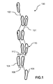
- Fig. 1 is a schematic view of a typical bipedal walk cycle 100.
- a typical human or bipedal walk cycle 100 for generally linear forward motion incorporates a right foot sinuous path 101 and a left foot sinuous path 102.
- a biped walk cycle 100 producing forward generally linear motion is achieved.
- a forward foot 104 carries the majority of the weight of a person.
- the rearward foot 106 is then lifted and moved in a generally forward direction, as indicated by the directional arrows.
- a minimum interspatial distance 108 between the two feet 104, 106 is defined when the initially forward foot 104 and the initially rearward foot 106 achieve a minimum separation distance.
- the initially rearward foot 106 usually carries no body weight and the initially forward foot 104 bears the entire body weight of the person.
- the initially rearward foot 106 curves away from the initially forward foot 104 and contacts the ground surface at a position 110 that is located generally forward of the initially forward foot 104 and achieves a maximum interspatial distance 112.
- the weight of the person is distributed between both initially forward and rearward feet 104, 106.
- the walk cycle 100 is repeated for the initially forward foot 104 in a similar manner as previously described but with the roles of the feet reversed.
- foot 106 carrying the majority of the weight of the person
- foot 104 is then lifted and moved in a generally forward direction, as indicated by the directional arrows.
- the path of foot 104 curves inwards towards foot 106 to form an arcuate path.
- the minimum interspatial distance 108 between the two feet 104, 106 is defined when foot 104 and foot 106 achieve a minimum separation distance.
- foot 104 usually carries no body weight and foot 106 bears the entire body weight of the person.
- foot 104 curves away from foot 106 and contacts the ground surface at a position that is located generally forward of foot 106 and achieves the maximum interspatial distance 112. As foot 104 makes supportive contact with the ground surface, the weight of the person is distributed between both feet 104, 106.
- the exact form of right and left sinuous paths 101, 102 is generally a product of body mechanics, such as hip rotation, weight transfer and numerous other postural alignments that are required for bipedal motion.
- the minimum interspatial distance 108 can be less than 0.5 inch and is generally dependant upon the physical structure and other attributes of the person walking.
- the maximum interspatial distance 112 is generally about shoulder width of the person but may vary depending on the gait and stride of the person.
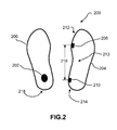
- Fig. 2 is an elevational view illustrating a pedometer generally designated with reference numeral 200 comprising a shoe mounted system capable of acquiring real time pedestrian performance data during ambulatory pedestrian motion.
- pedometer 200 is incorporated into a right shoe 204 and a corresponding left shoe 206. Both right and left shoes 204, 206 generally form a matching pair of shoes suitable for wear and use in ambulatory motion such as walking, running, and jogging.
- the right shoe 204 has mounted thereon a first signal generator 208 and a second signal generator 210.
- first signal generator 208 is positioned adjacent a relatively forward portion 212 of right shoe 204 and the second signal generator 210 is positioned adjacent a relatively rearward portion 214 of right shoe 204.
- Both first and second signal generators 208, 210 are preferably positioned along the inner margin of right shoe 204 so as to be nearest to the corresponding left shoe 206 and proximate an instep region 213 of right shoe 204.
- first and second signal generators 208, 210 are each fabricated from permanent magnetic material that produces magnetic fields sufficient to reach a region of left shoe 206 at which a sensor 202 is located.
- a signal generator longitudinal separation distance 216 defines a fixed distance between first and second signal generators 208, 210 along the generally longitudinal axis of right shoe 204.
- longitudinal separation distance 216 is approximately five inches; however, it is contemplated that other fixed dimensions for longitudinal separation distance 216 may be used depending on the relative size and configuration of the shoes.
- signal generators 208, 210 are embedded within a sole (not shown) forming a part of right shoe 204. It is understood that signal generators 208, 210 may be incorporated into other components of right shoe 204 by molding or adhesing, or mechanically attached to an appropriate portion of right shoe 204 by any suitable attachment technique, such as loop-and-hook fastener material sold under the trademark Velcro.
- sensor and transmitter assembly 202 located in a fixed position of left shoe 206.
- sensor and transmitter assembly 202 comprises at least one proximity sensor (such as a Hall effect sensor) capable of sensing the magnetic field signals generated by generators 208, 210 mounted on right shoe 204, a microcontroller unit and a transmitter. These elements are discussed in further detail below with respect to Fig. 3 . It is contemplated that sensor and transmitter assembly 202 is embedded within a sole (not shown) forming a part of left shoe 206. In alternate embodiments, sensor and transmitter assembly 202 may be coupled to other components and regions of left shoe 204.
- signal generators 208, 210 have been described with respect to the right shoe and the sensor and transmitter assembly 202 has been described with respect to the left shoe 206, one having ordinary skill in the art will readily appreciate that reversing the right and left shoe configurations is also possible.
- Fig. 3 is a block diagram of the pedometer of Fig. 2 having shoe mounted signal generators 208, 210, and a shoe mounted sensor and transmitter assembly 202 and an associated separate display unit 300.
- a proximity sensor 302 is positioned in operable range with first and second signal generators 208, 210 such that magnetic impulse signals are induced in sensor 302 when relative motion exists between right and left shoes 204, 206 in such a manner that signal generators 208, 210 pass by the region of left shoe 206 within the operational range of proximity sensor 302.
- proximity sensor 302 is preferably a Hall-effect sensor available from Allegro Microsystems, Inc., part number: A1395SEHLT.
- proximity sensor 302 may be an MR sensor available from Honeywell Microelectronics, part number: HMC1001.
- Proximity sensor 302 is operatively coupled with a microcontroller unit (MCU) 304 such that magnetic impulse signals received by proximity sensor 302 are converted to electrical signals which are coupled to MCU 304 for various signal processing functions (discussed in further detail below with respect to Figs. 5 & 6 ).
- MCU 304 is operatively coupled with transmitter 306 for wireless transmission of processed pedestrian performance data to display unit 300.
- Performance data may include: total steps, steps per minute, instantaneous foot speed, average foot speed, cadence, total distance travelled, distance per stride, calories burned and other parametric data produced by MCU 304.
- MCU 304 and transmitter 306 are preferably combined in a type AT3 chipset available as SensRcore part number nRF24LO1 from ANT of Cochrane, Alberta, Canada.
- Transmitter 306 communicates wirelessly with display unit 300 by either unidirectionally or bidirectionally transferring performance data and step information thereto .
- display unit 300 may be a third party performance monitoring device or fitness computer such as the Edge 705 unit available from Garmin Ltd., part number 010-00555-20.
- transmitter 306 may be configured to communicate and transfer performance data to other electronic devices such as a cell phone, an Mp3 player or other portable display device.
- the wireless communication protocol used between transmitter 306 and display unit 300 is a wireless sensor network communication protocol commonly referred to as "ANT" available from Dynastream Innovations, Inc. of Cochrane, Alberta, Canada.
- ANT wireless sensor network communication protocol
- Some features of the ANT protocol include low power consumption, low cost overhead, and the ability of multiple transceivers to co-exist in close proximity to other similar transceivers.
- the ANT protocol has an estimated efficiency of about 47 percent due to various programming configurations that reduce power consumption in a standby state.
- other types of wireless communication protocols such as Bluetooth or ZigBee (based upon IEEE standard 802.15.4) may be utilized to facilitate data transfer between transmitter 306 and display unit 300.
- a suitable source of D.C. electrical power such as a battery (not shown) is used to power the system elements 302, 304, and 306 shown in Fig. 3 .
- the magnetic fields generated by magnets 208, 210 can serve as an energy source when combined with a coil and a D.C. rectifier circuit included in assembly 202. This arrangement eliminates the need to replace a battery when the useful energy is depleted from the battery.
- Display unit 300 is provided with a separate power source, such as a battery.
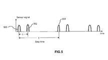
- Fig. 4 is an enlarged schematic view of a representative portion of a bipedal ambulatory cycle 100 and Fig. 5 is a graph illustrating sensor signals versus time.
- the pedometer of the present invention generates a step count and step time as one shoe passes by the other shoe.
- first and second signal generators 208, 210 are successively brought into close proximity with sensor and transmitter assembly 202.
- a first impulse signal 500 ( Fig. 5 ) is generated by sensor 302 ( Fig.
- This first impulse signal is coupled to MCU304 ( Fig. 3 ) in sensor and transmitter assembly 202.
- the second signal generator 210 passes the proximity sensor within assembly 202 and generates a second impulse signal 502 that is received by MCU 304.
- This pair of first and second impulse signals 500, 502 is separated by a first time interval "t", which can be determined by MCU 304 given the known separation distance between signal generators 208, 210.
- a third impulse signal 504 is generated at a second time interval as the proximity sensor 302 contained within sensor and transmitter assembly 202 moves by the second signal generator 210. Once the third impulse signal 504 is generated, the value of a parameter termed step time "T" can be determined by MCU 304.
- Pedometer cadence is calculated by dividing the total number of steps by the sum total of step time. The cadence value may then be converted into various units such as steps/minute by applying standard time conversions. For total distance traveled, and referring to Fig. 6 , first an average foot speed V1 is determined over first time interval "t". Average foot speed is calculated by using the fixed separation distance between the first and second signal generators 208, 210 and first time interval "t".
- a coefficient "K” is used to proportionally scale average foot speed V1 to average step speed V2.
- the resulting performance data determined by MCU 304 can be stored in MCU 304 memory for subsequent analysis, and also transmitted by transmitter 306 to display unit 300 to provide real time performance data feedback to the user.
- signal generators 208, 210 and sensor 302 may be implemented using other technologies, such as optical and r.f. technologies.
- signal generators 208, 210 may comprise light emitting diodes (LEDs) which generate light beams of a known wave length
- sensor 302 may comprise an optical sensor for sensing light radiation at the LED wave length.
- a source of electrical energy such as a battery, must be provided to power the LED signal generators 208, 210.
- r.f. technology signal generators 208, 210 may comprise RFID tags which generate r.f.
- sensor 302 may comprise an RFID reader/interrogator unit capable of sensing r.f. signals at the known frequency.
- the RFID tags may comprise active or passive RFID tags. If active RFID tags are employed, a source of electrical energy, such as a battery, must be provided to power the RFI D tags. If passive RFI D tags are employed, they will be powered by the r.f. interrogation signals from sensor 302 and no separate electrical power source is required for the signal generators 208, 210.
- One suitable choice for a passive RFI D tag is an Atmel type ATA5577 RFID tag available from Atmel Corporation of San Jose, California.
- One suitable choice for an RFID reader/interrogator is an Atmel type ATA5577 device, also available from Atmel Corporation of San Jose, California.
- pedometers fabricated according to the teachings of the present invention offer accuracy and convenience advantages over known pedometers.
- the use of a shoe mounted proximity sensor and signal generator provides improved accuracy for determining step count. This improved accuracy results from generating impulse signals each time the feet pass by each other.
- pedometers fabricated according to the teachings of the present invention reduce the number of recorded "false steps" by eliminating reliance on mechanical movements and axial alignment of accelerometers.
- a shoe-mounted sensor and transmitter that wirelessly communicates with a separate display, greater user convenience is achieved over pedometers that have integral display units.
- the proximity sensor and signal generator configuration shown in Figs. 2-5 a high level of step count accuracy can be achieved at very low walking speeds.
Abstract
Description
- This invention relates to pedometers used to measure pedestrian step counts and calculate distances traveled on foot. More particularly, this invention relates to a pedometer that comprises a shoe mounted system that acquires pedestrian performance data and transmits calculated results to a separate display unit.
- Pedometers are being increasingly used by both professional and amateur fitness enthusiasts as an aid in monitoring and evaluating exercise routines. By using a pedometer, a person can measure and record a variety of data parameters, such as: step count, distance traveled, speed, and calories burned to name a few. These parameters are useful in determining the effectiveness and efficiency of a particular fitness program. Additionally, a pedometer may be used as a motivational device by providing a person with a way to track their daily physical activity level and correspondingly establish increased activity level targets. The use of a pedometer, in many instances, has motivated people to significantly increase their physical activity levels resulting in lower blood pressure, weight loss and better overall fitness.
- Several different types of pedometers are known and are currently available. These known pedometers utilize a range of technologies to determine step counts and distances. One classic type of known pedometer is a mechanical device that uses a pendulum to detect physical motion and then convert that motion into a step count. A person typically wears the mechanical pedometer on their belt in a substantially vertical orientation. As the person walks, their hips induce a swinging motion into the pedometer, which in turn causes a weighted pendulum to move within the pedometer housing. The inertia of the pendulum is sensed by means of a ratchet mechanism or mechanical stop, which thereby advances a mechanical counter. While somewhat useful, pedometers using a pendulum to detect steps frequently record "false steps" or erroneous movements such as bending over and leaning. Moreover, pendulum actuated pedometers are sensitive to proper vertical alignment and usually require mechanical adjustment in relation to the gait/stride of the user in order to accurately record steps and convert the number of steps to a distance value.
- Other types of known pedometers use electro-mechanical systems to detect and record a step count. Once such pedometer counts steps by means of one or more electro-mechanical switches embedded within a shoe. As a person steps, the switch is either opened or closed creating an electrical signal which is used to increment an electronic counter. Although this type of pedometer is usually more accurate than pendulum-type pedometers, false steps are still frequently recorded such as when a person shifts their weight from one foot to another. In addition, it is more than a trivial task to incorporate the switches in a shoe so that the switches reliably sense each step. Further, the switches are prone to contamination in situ and are susceptible to wear given the harsh environment in which they are located.
- More sophisticated electro-mechanical pedometers use one or more accelerometers and microprocessors properly programmed to detect pedestrian steps. These pedometers generally have 1-, 2- or 3-axis accelerometers to measure accelerations and generate electronic signals corresponding to physical movement. The software in the microprocessor then processes the electronic acceleration signals to determine step count, step frequency and stride length. While this type of pedometer is useful and possibly more accurate than pendulum based and switch based pedometers at high-frequency step counts, false steps and erroneous distances can be generated during low speed movement. Additionally, improper axial alignment of the accelerometers during use can adversely affect the accuracy of these pedometers.
- In one known accelerometer-type pedometer described in
U.S. Patent Number 6,145,389 to Ebeling et al., November 14, 2000 (the entire disclosure of which is hereby incorporated by reference) an accelerometer is attached to a shoe and a microprocessor uses the signals generated by the accelerometer to calculate stride length. This pedometer requires that the accelerometer be carefully aligned such that the axis of acceleration measurement is substantially aligned with the direction of pedestrian foot travel. Correspondingly, should improper axial alignment of the accelerometer occur during use, incomplete and inaccurate measurements can result. - In another known accelerometer-type pedometer described in
U.S. Patent Number 6,175,608 to Pyles et al., January 16, 2001 (the entire disclosure of which is hereby incorporated by reference) an inertial device is mounted to the waist, chest, or leg of a user to determine stride count. The inertial device of this pedometer detects gross physical movements similar to pendulum-type pedometers. While this type of pedometer is useful, false steps or irrelevant movements, such as bending over and leaning, may be erroneously recorded as steps. Moreover, since the inertial device determines step count based on acceleration, low-speed steps may not be accurately detected. Additionally, improper alignment of the inertial device during use may adversely affect the accuracy of these pedometers. - Efforts to provide a pedometer devoid of the above-noted disadvantages have not met with success to date.
- The invention comprises a pedometer which is devoid of the above-noted disadvantages, which substantially reduces false step count readings and provides high accuracy at low speeds, and which is relatively simple to implement in existing foot wear.
- In a broadest aspect, the invention comprises a pedometer having a first signal generator carried by a first portion of a first shoe; a second signal generator carried by a second portion of the first shoe, the first and second signal generators being separated by a fixed distance; and a sensor assembly coupled with a second shoe, the sensor assembly including a sensor for sensing signals generated by the first and second signal generators and for generating corresponding electrical signals, and a microcontroller unit having an input coupled to the sensor for receiving the corresponding electrical signals and converting the corresponding electrical signals into pedestrian performance data. The first and second signal generators and the sensor are preferably aligned on the first and second shoes in facing relation when the first and second shoes are worn by a user so as to maximize the incidence of detection of the signals from the first and second signal generators by the sensor.
- Preferably, the first and second signal generators are mounted adjacent the inner margin of the first shoe, and the sensor is mounted adjacent the inner margin of the second shoe. The fixed separation distance between the first and second signal generators preferably extends generally longitudinally of the first shoe.
- The first and second signal generators and the sensor are alternately implemented using a variety of technologies. In a magnetic technology implementation, the first and second signal generators comprise permanent magnets; and the sensor comprises a device such as a Hall effect sensor or an MR sensor for converting the magnetic fields generated by the permanent magnets to corresponding electrical signals. In an optical technology implementation, the first and second signal generators comprise light radiation sources, such as light emitting diodes; and the sensor comprises a device for converting the light radiation generated by the light radiation sources to corresponding electrical signals. In an r.f. technology implementation, the first and second signal generators comprise RFID tags for generating r.f. signals of known frequency; and the sensor comprises an RFID reader device for converting r.f. signals received from the RFID tags to corresponding electrical signals. The RFID signal generator tags may comprise either active or passive RFID tags.
- The pedometer may further include a transmitter coupled to the microcontroller unit for transmitting the pedestrian performance data to a receiver/ display unit to provide real time user feedback.
- Pedometers fabricated according to the teachings of the invention are simple to incorporate into foot wear at the point of manufacture or as an after market item at relatively low cost. Such pedometers are capable of providing accurate pedestrian performance data, such as foot speed, step count, distance travelled, cadence and many other performance parameters of potential interest to users.
- For a fuller understanding of the nature and advantages of the invention, reference should be made to the ensuing detailed description taken in conjunction with the accompanying drawings.
- In the drawings, like reference characters generally refer to the same parts throughout the different views. Also, the drawings are not necessarily to scale, emphasis instead generally being placed upon illustrating the principles of the invention. In the following description, various embodiments of the present invention are described with reference to the following drawings, in which:
-
FIG. 1 is schematic view of a bipedal walk cycle; -
FIG. 2 is an elevational view illustrating a shoe mounted pedometer according to the invention; -
FIG. 3 is a block diagram of a pedometer having a shoe mounted signal generator, a sensor and transmitter and an associated separate pedestrian parameter display unit; -
FIG. 4 is an enlarged schematic view of a typical biped walk cycle; -
FIG. 5 is a graph illustrating sensor signals versus time; and -
FIG. 6 is a graph illustrating foot speed versus time. - Turning now to the drawings,
Fig. 1 is a schematic view of a typicalbipedal walk cycle 100. As seen in this Fig., a typical human orbipedal walk cycle 100 for generally linear forward motion incorporates a right footsinuous path 101 and a left footsinuous path 102. When both the right and left footsinuous paths biped walk cycle 100 producing forward generally linear motion is achieved. To begin awalk cycle 100, aforward foot 104 carries the majority of the weight of a person. Therearward foot 106 is then lifted and moved in a generally forward direction, as indicated by the directional arrows. As therearward foot 106 moves towards theforward foot 104, the motion ofrearward foot 106 curves inwards towards theforward foot 104 to form an arcuate path. Aminimum interspatial distance 108 between the twofeet forward foot 104 and the initiallyrearward foot 106 achieve a minimum separation distance. At this point in thewalk cycle 100, the initiallyrearward foot 106 usually carries no body weight and the initiallyforward foot 104 bears the entire body weight of the person. Next, the initially rearward foot 106 curves away from the initiallyforward foot 104 and contacts the ground surface at aposition 110 that is located generally forward of the initiallyforward foot 104 and achieves amaximum interspatial distance 112. As initiallyrearward foot 106 makes supportive contact with the ground surface, the weight of the person is distributed between both initially forward andrearward feet - As shown in
Fig. 1 , thewalk cycle 100 is repeated for the initiallyforward foot 104 in a similar manner as previously described but with the roles of the feet reversed. Thus, withfoot 106 carrying the majority of the weight of the person,foot 104 is then lifted and moved in a generally forward direction, as indicated by the directional arrows. Asfoot 104 moves towardsfoot 106, the path offoot 104 curves inwards towardsfoot 106 to form an arcuate path. Theminimum interspatial distance 108 between the twofeet foot 104 andfoot 106 achieve a minimum separation distance. At this point in thewalk cycle 100,foot 104 usually carries no body weight andfoot 106 bears the entire body weight of the person. Next, foot 104 curves away fromfoot 106 and contacts the ground surface at a position that is located generally forward offoot 106 and achieves themaximum interspatial distance 112. Asfoot 104 makes supportive contact with the ground surface, the weight of the person is distributed between bothfeet - The exact form of right and left
sinuous paths minimum interspatial distance 108 can be less than 0.5 inch and is generally dependant upon the physical structure and other attributes of the person walking. Themaximum interspatial distance 112 is generally about shoulder width of the person but may vary depending on the gait and stride of the person. - Due to the close proximity of both feet at the
minimum interspatial distance 108, it is possible to implement shoe mounted signal generators and a proximity sensor to detect when the feet pass each other during the walk cycle. Detection of the passing feet is discussed in further detail below with respect toFig. 4 . - Reference is now made to
Fig. 2 , which is an elevational view illustrating a pedometer generally designated withreference numeral 200 comprising a shoe mounted system capable of acquiring real time pedestrian performance data during ambulatory pedestrian motion. As shown inFig. 2 ,pedometer 200 is incorporated into aright shoe 204 and a correspondingleft shoe 206. Both right and leftshoes right shoe 204 has mounted thereon afirst signal generator 208 and asecond signal generator 210. Thefirst signal generator 208 is positioned adjacent a relativelyforward portion 212 ofright shoe 204 and thesecond signal generator 210 is positioned adjacent a relativelyrearward portion 214 ofright shoe 204. Both first andsecond signal generators right shoe 204 so as to be nearest to the correspondingleft shoe 206 and proximate aninstep region 213 ofright shoe 204. In an exemplary embodiment, first andsecond signal generators left shoe 206 at which asensor 202 is located. As will be apparent to those of ordinary skill in the art, many different types of magnetic material may be used, such as ferromagnetic materials (e.g., cobalt and nickel) and ferrimagnetic materials, and composites such as Alnico, Ticonal, and sintered composites of powdered iron oxide and barium/strontium carbonate ceramic. A signal generatorlongitudinal separation distance 216 defines a fixed distance between first andsecond signal generators right shoe 204. In an exemplary embodiment,longitudinal separation distance 216 is approximately five inches; however, it is contemplated that other fixed dimensions forlongitudinal separation distance 216 may be used depending on the relative size and configuration of the shoes. In an exemplary embodiment, signalgenerators right shoe 204. It is understood thatsignal generators right shoe 204 by molding or adhesing, or mechanically attached to an appropriate portion ofright shoe 204 by any suitable attachment technique, such as loop-and-hook fastener material sold under the trademark Velcro. -
Left shoe 206 has mounted thereon a sensor andtransmitter assembly 202 located in a fixed position ofleft shoe 206. In an exemplary embodiment, sensor andtransmitter assembly 202 comprises at least one proximity sensor (such as a Hall effect sensor) capable of sensing the magnetic field signals generated bygenerators right shoe 204, a microcontroller unit and a transmitter. These elements are discussed in further detail below with respect toFig. 3 . It is contemplated that sensor andtransmitter assembly 202 is embedded within a sole (not shown) forming a part ofleft shoe 206. In alternate embodiments, sensor andtransmitter assembly 202 may be coupled to other components and regions ofleft shoe 204. Althoughsignal generators transmitter assembly 202 has been described with respect to theleft shoe 206, one having ordinary skill in the art will readily appreciate that reversing the right and left shoe configurations is also possible. -
Fig. 3 is a block diagram of the pedometer ofFig. 2 having shoe mountedsignal generators transmitter assembly 202 and an associatedseparate display unit 300. As seen in this Fig., aproximity sensor 302 is positioned in operable range with first andsecond signal generators sensor 302 when relative motion exists between right and leftshoes generators left shoe 206 within the operational range ofproximity sensor 302. In the magnetic implementation being described,proximity sensor 302 is preferably a Hall-effect sensor available from Allegro Microsystems, Inc., part number: A1395SEHLT. Alternatively,proximity sensor 302 may be an MR sensor available from Honeywell Microelectronics, part number: HMC1001. -
Proximity sensor 302 is operatively coupled with a microcontroller unit (MCU) 304 such that magnetic impulse signals received byproximity sensor 302 are converted to electrical signals which are coupled toMCU 304 for various signal processing functions (discussed in further detail below with respect toFigs. 5 &6 ).MCU 304 is operatively coupled withtransmitter 306 for wireless transmission of processed pedestrian performance data to displayunit 300. Performance data may include: total steps, steps per minute, instantaneous foot speed, average foot speed, cadence, total distance travelled, distance per stride, calories burned and other parametric data produced byMCU 304.MCU 304 andtransmitter 306 are preferably combined in a type AT3 chipset available as SensRcore part number nRF24LO1 from ANT of Cochrane, Alberta, Canada.Transmitter 306 communicates wirelessly withdisplay unit 300 by either unidirectionally or bidirectionally transferring performance data and step information thereto . It is contemplated thatdisplay unit 300 may be a third party performance monitoring device or fitness computer such as the Edge 705 unit available from Garmin Ltd., part number 010-00555-20. In an alternate embodiment,transmitter 306 may be configured to communicate and transfer performance data to other electronic devices such as a cell phone, an Mp3 player or other portable display device. - In an exemplary embodiment, the wireless communication protocol used between
transmitter 306 anddisplay unit 300 is a wireless sensor network communication protocol commonly referred to as "ANT" available from Dynastream Innovations, Inc. of Cochrane, Alberta, Canada. Some features of the ANT protocol include low power consumption, low cost overhead, and the ability of multiple transceivers to co-exist in close proximity to other similar transceivers. The ANT protocol has an estimated efficiency of about 47 percent due to various programming configurations that reduce power consumption in a standby state. However, one having ordinary skill in the art would readily appreciate that other types of wireless communication protocols such as Bluetooth or ZigBee (based upon IEEE standard 802.15.4) may be utilized to facilitate data transfer betweentransmitter 306 anddisplay unit 300. - A suitable source of D.C. electrical power, such as a battery (not shown) is used to power the
system elements Fig. 3 . In the alternative, the magnetic fields generated bymagnets assembly 202. This arrangement eliminates the need to replace a battery when the useful energy is depleted from the battery.Display unit 300 is provided with a separate power source, such as a battery. - Reference is now made to
Figs. 4 and5 , in whichFig. 4 is an enlarged schematic view of a representative portion of a bipedalambulatory cycle 100 andFig. 5 is a graph illustrating sensor signals versus time. The pedometer of the present invention generates a step count and step time as one shoe passes by the other shoe. For example, inFig. 4 , asright shoe 204 follows the right footsinuous path 101, first andsecond signal generators transmitter assembly 202. At theminimum interspatial distance 108, and as thefirst signal generator 208 passes by the proximity sensor withinassembly 202, a first impulse signal 500 (Fig. 5 ) is generated by sensor 302 (Fig. 3 ) with the maximum value occurring at the point of closest approach betweengenerator 208 andsensor 302. This first impulse signal is coupled to MCU304 (Fig. 3 ) in sensor andtransmitter assembly 202. As theright shoe 204 moves an additional distance forward, equal to the fixedlongitudinal separation distance 216, thesecond signal generator 210 passes the proximity sensor withinassembly 202 and generates asecond impulse signal 502 that is received byMCU 304. This pair of first and second impulse signals 500, 502 is separated by a first time interval "t", which can be determined byMCU 304 given the known separation distance betweensignal generators left shoe 206 progresses to the next step in thewalk cycle 100, athird impulse signal 504 is generated at a second time interval as theproximity sensor 302 contained within sensor andtransmitter assembly 202 moves by thesecond signal generator 210. Once thethird impulse signal 504 is generated, the value of a parameter termed step time "T" can be determined byMCU 304. - Upon acquiring the real time pedestrian data "t" and "T" as discussed above, various other performance parameters can be calculated such as cadence, speed and total distance traveled. Pedometer cadence is calculated by dividing the total number of steps by the sum total of step time. The cadence value may then be converted into various units such as steps/minute by applying standard time conversions. For total distance traveled, and referring to
Fig. 6 , first an average foot speed V1 is determined over first time interval "t". Average foot speed is calculated by using the fixed separation distance between the first andsecond signal generators second signal generators MCU 204 using standard techniques. - The resulting performance data determined by
MCU 304 can be stored inMCU 304 memory for subsequent analysis, and also transmitted bytransmitter 306 to displayunit 300 to provide real time performance data feedback to the user. - Although described above as operating in the magnetic domain, signal
generators sensor 302 may be implemented using other technologies, such as optical and r.f. technologies. For example, for an implementation using opticaltechnology signal generators sensor 302 may comprise an optical sensor for sensing light radiation at the LED wave length. In such an implementation, a source of electrical energy, such as a battery, must be provided to power theLED signal generators technology signal generators sensor 302 may comprise an RFID reader/interrogator unit capable of sensing r.f. signals at the known frequency. The RFID tags may comprise active or passive RFID tags. If active RFID tags are employed, a source of electrical energy, such as a battery, must be provided to power the RFI D tags. If passive RFI D tags are employed, they will be powered by the r.f. interrogation signals fromsensor 302 and no separate electrical power source is required for thesignal generators - As will now be apparent, pedometers fabricated according to the teachings of the present invention offer accuracy and convenience advantages over known pedometers. Firstly, the use of a shoe mounted proximity sensor and signal generator provides improved accuracy for determining step count. This improved accuracy results from generating impulse signals each time the feet pass by each other. In addition, pedometers fabricated according to the teachings of the present invention reduce the number of recorded "false steps" by eliminating reliance on mechanical movements and axial alignment of accelerometers. Further, by employing a shoe-mounted sensor and transmitter that wirelessly communicates with a separate display, greater user convenience is achieved over pedometers that have integral display units. Lastly, by employing the proximity sensor and signal generator configuration shown in
Figs. 2-5 , a high level of step count accuracy can be achieved at very low walking speeds. - While the invention has been described with reference to particular embodiments, various modifications, alternate constructions and equivalents may be employed without departing from the spirit of the invention. For example, while certain circuit components have been disclosed, other equivalent units may be employed, as desired. Therefore, the above should not be construed as limiting the invention, which is defined by the appended claims.
Claims (15)
- A pedometer comprising:a first signal generator carried by a first portion of a first shoe;a second signal generator carried by a second portion of said first shoe, said first and second signal generators being separated by a fixed distance; anda sensor assembly coupled with a second shoe, said sensor assembly including a sensor for sensing signals generated by said first and second signal generators and for generating corresponding electrical signals, and a microcontroller unit having an input coupled to said sensor for receiving said corresponding electrical signals and converting said corresponding electrical signals into pedestrian performance data.
- The pedometer of claim 1 wherein said first and second signal generators and said sensor are aligned on said first and second shoes in facing relation when said first and second shoes are worn by a user.
- The pedometer of claim 1 or claim 2 wherein said first shoe has an inner margin; and wherein said first and second signal generators are mounted adjacent said inner margin of said first shoe.
- The pedometer of claim 3 wherein said second shoe has an inner margin; and wherein said sensor is mounted adjacent said inner margin of said second shoe.
- The pedometer of any preceding claim wherein said first and second signal generators comprise permanent magnets; and wherein said sensor comprises a device for converting the magnetic fields generated by said permanent magnets to corresponding electrical signals.
- The pedometer of claim 5 wherein said sensor comprises a Hall effect sensor device.
- The pedometer of claim 5 wherein said sensor comprises an MR sensor device.
- The pedometer of any of claims 1 to 4 wherein said first and second signal generators comprise light radiation sources; and wherein said sensor comprises a device for converting the light radiation generated by said light radiation sources to corresponding electrical signals.
- The pedometer of claim 8 wherein said light radiation sources are light emitting diodes.
- The pedometer of any of claims 1 to 4 wherein said first and second signal generators comprise RFID tags for generating r.f. signals of known frequency; and wherein said sensor comprises an RFID reader device for converting r.f. signals received from said RFID tags to corresponding electrical signals.
- The pedometer of claim 10 wherein said RFID tags are active RFID devices.
- The pedometer of claim 10 wherein said RFID tags are passive RFID devices.
- The pedometer of any preceding claim further including a transmitter coupled to said microcontroller unit for transmitting said pedestrian performance data to a receiver/ display unit to provide real time user feedback.
- The pedometer of any preceding claim wherein said fixed distance extends generally longitudinally of said first shoe.
- The pedometer of claim 14 wherein said first shoe has an inner margin; and wherein said first and second signal generators are located along said inner margin in the region of the instep of a foot inserted into said first shoe.
Priority Applications (1)
| Application Number | Priority Date | Filing Date | Title |
|---|---|---|---|
| EP10192636.8A EP2458338B1 (en) | 2010-11-25 | 2010-11-25 | Pedometer With Shoe Mounted Sensor And Transmitter |
Applications Claiming Priority (1)
| Application Number | Priority Date | Filing Date | Title |
|---|---|---|---|
| EP10192636.8A EP2458338B1 (en) | 2010-11-25 | 2010-11-25 | Pedometer With Shoe Mounted Sensor And Transmitter |
Publications (2)
| Publication Number | Publication Date |
|---|---|
| EP2458338A1 true EP2458338A1 (en) | 2012-05-30 |
| EP2458338B1 EP2458338B1 (en) | 2014-12-31 |
Family
ID=43759481
Family Applications (1)
| Application Number | Title | Priority Date | Filing Date |
|---|---|---|---|
| EP10192636.8A Not-in-force EP2458338B1 (en) | 2010-11-25 | 2010-11-25 | Pedometer With Shoe Mounted Sensor And Transmitter |
Country Status (1)
| Country | Link |
|---|---|
| EP (1) | EP2458338B1 (en) |
Cited By (4)
| Publication number | Priority date | Publication date | Assignee | Title |
|---|---|---|---|---|
| US20140088917A1 (en) * | 2012-09-26 | 2014-03-27 | Stmicroelectronics S.R.L. | Step counter device with energy-scavenging functionality, and step-counting method |
| EP2918975A1 (en) * | 2014-03-13 | 2015-09-16 | STMicroelectronics Srl | Energy scavenging step-counter device and related step-counting method |
| US20170241797A1 (en) * | 2016-02-01 | 2017-08-24 | One Two Free Inc. | Pedometer with Accelerometer and Foot Motion Distinguishing Method |
| FR3072251A1 (en) * | 2017-10-16 | 2019-04-19 | Zhor Tech | ELECTRONIC DEVICE FOR FOOTWEAR PRODUCTS. |
Citations (6)
| Publication number | Priority date | Publication date | Assignee | Title |
|---|---|---|---|---|
| WO1998000683A1 (en) * | 1996-06-28 | 1998-01-08 | Alberto Gregori | Pedometer |
| WO1999065385A1 (en) * | 1997-01-27 | 1999-12-23 | Ng Kim Kwee | The activity monitor |
| US6145389A (en) | 1996-11-12 | 2000-11-14 | Ebeling; W. H. Carl | Pedometer effective for both walking and running |
| US6175608B1 (en) | 1998-10-28 | 2001-01-16 | Knowmo Llc | Pedometer |
| WO2007008352A1 (en) * | 2005-07-11 | 2007-01-18 | Nike, Inc. | Control systems and foot-receiving device products containing such systems |
| WO2008042720A1 (en) * | 2006-09-29 | 2008-04-10 | Intel Corporation | Method and apparatus for a self-powered rfid-readable pedometer |
Family Cites Families (1)
| Publication number | Priority date | Publication date | Assignee | Title |
|---|---|---|---|---|
| DE202006009810U1 (en) * | 2006-06-21 | 2006-08-31 | Werfel, Frank, Dr. | Pedometer system, using speed and time measurements, has two transceivers at one shoe and a further transceiver at the other shoe with a passive energy supply |
-
2010
- 2010-11-25 EP EP10192636.8A patent/EP2458338B1/en not_active Not-in-force
Patent Citations (6)
| Publication number | Priority date | Publication date | Assignee | Title |
|---|---|---|---|---|
| WO1998000683A1 (en) * | 1996-06-28 | 1998-01-08 | Alberto Gregori | Pedometer |
| US6145389A (en) | 1996-11-12 | 2000-11-14 | Ebeling; W. H. Carl | Pedometer effective for both walking and running |
| WO1999065385A1 (en) * | 1997-01-27 | 1999-12-23 | Ng Kim Kwee | The activity monitor |
| US6175608B1 (en) | 1998-10-28 | 2001-01-16 | Knowmo Llc | Pedometer |
| WO2007008352A1 (en) * | 2005-07-11 | 2007-01-18 | Nike, Inc. | Control systems and foot-receiving device products containing such systems |
| WO2008042720A1 (en) * | 2006-09-29 | 2008-04-10 | Intel Corporation | Method and apparatus for a self-powered rfid-readable pedometer |
Cited By (11)
| Publication number | Priority date | Publication date | Assignee | Title |
|---|---|---|---|---|
| US20140088917A1 (en) * | 2012-09-26 | 2014-03-27 | Stmicroelectronics S.R.L. | Step counter device with energy-scavenging functionality, and step-counting method |
| ITTO20120833A1 (en) * | 2012-09-26 | 2014-03-27 | St Microelectronics Srl | COUNTERPASS DEVICE EQUIPPED WITH FUNCTIONALITY OF ENERGY COLLECTION AND METHOD OF COUNTING STEPS |
| US9587959B2 (en) | 2012-09-26 | 2017-03-07 | Stmicroelectronics S.R.L. | Step counter device with energy-scavenging functionality, and step-counting method |
| EP2918975A1 (en) * | 2014-03-13 | 2015-09-16 | STMicroelectronics Srl | Energy scavenging step-counter device and related step-counting method |
| US20170241797A1 (en) * | 2016-02-01 | 2017-08-24 | One Two Free Inc. | Pedometer with Accelerometer and Foot Motion Distinguishing Method |
| US11047706B2 (en) * | 2016-02-01 | 2021-06-29 | One Two Free Inc. | Pedometer with accelerometer and foot motion distinguishing method |
| FR3072251A1 (en) * | 2017-10-16 | 2019-04-19 | Zhor Tech | ELECTRONIC DEVICE FOR FOOTWEAR PRODUCTS. |
| FR3072271A1 (en) * | 2017-10-16 | 2019-04-19 | Zhor Tech | MINIATURIZED ELECTRONIC HOUSING INTEGRABLE IN ANY SOLE |
| WO2019077266A1 (en) * | 2017-10-16 | 2019-04-25 | Zhor Tech | Miniaturized electronic unit for integration in any sole |
| KR20200067878A (en) * | 2017-10-16 | 2020-06-12 | 조르텍 | Small electronic box that can be integrated into any sole |
| US10966638B2 (en) | 2017-10-16 | 2021-04-06 | Zhor Tech | Miniaturized electronic unit for integration in any sole |
Also Published As
| Publication number | Publication date |
|---|---|
| EP2458338B1 (en) | 2014-12-31 |
Similar Documents
| Publication | Publication Date | Title |
|---|---|---|
| US8990045B2 (en) | Pedometer with shoe mounted sensor and transmitter | |
| US11511154B1 (en) | Athletic performance and technique monitoring | |
| US8876738B1 (en) | Human activity monitoring device | |
| CN104165637B (en) | Method and apparatus for the attachment position for determining motion sensing apparatus | |
| Wahab et al. | Gait analysis measurement for sport application based on ultrasonic system | |
| EP2910901B1 (en) | Method for determining an instant velocity of a user and for improving estimation of heart rate | |
| EP2947588B1 (en) | Method for calculating the activity of a user | |
| US5899963A (en) | System and method for measuring movement of objects | |
| US8460001B1 (en) | Athletic performance monitoring with overstride detection | |
| US20060161079A1 (en) | Method and apparatus for monitoring human activity pattern | |
| US20030163283A1 (en) | Exercise monitoring apparatus | |
| US20150198460A1 (en) | Wristband-type arm movement determination device and wristband-type activity tracker | |
| EP2458338B1 (en) | Pedometer With Shoe Mounted Sensor And Transmitter | |
| WO2000036520A9 (en) | System and method for measuring movement of objects | |
| WO2008042720A1 (en) | Method and apparatus for a self-powered rfid-readable pedometer | |
| EP3196597A1 (en) | A system and method for linking oscillating movements of exercise equipment to a user of the exercise equipment in a database | |
| Ryu et al. | Adaptive step detection algorithm for wireless smart step counter | |
| CN102564448B (en) | There is the pedometer of footwear dress sensor and transmitter | |
| Sundaravadivel et al. | Smart-walk: An intelligent physiological monitoring system for smart families | |
| JP5616763B2 (en) | Pedometer with shoe-mounted sensor and transmitter | |
| US9427646B2 (en) | Lower leg sensing device and method of providing data therefrom | |
| TWI495849B (en) | Pedometer with shoe mounted sensor and transmitter | |
| US20090063088A1 (en) | Wristwatch type acceleration detection module | |
| KR20120100059A (en) | A system for measuring the information of a pedestrian | |
| US20160025513A1 (en) | Multi-sensor pedometer |
Legal Events
| Date | Code | Title | Description |
|---|---|---|---|
| PUAI | Public reference made under article 153(3) epc to a published international application that has entered the european phase |
Free format text: ORIGINAL CODE: 0009012 |
|
| AK | Designated contracting states |
Kind code of ref document: A1 Designated state(s): AL AT BE BG CH CY CZ DE DK EE ES FI FR GB GR HR HU IE IS IT LI LT LU LV MC MK MT NL NO PL PT RO RS SE SI SK SM TR |
|
| AX | Request for extension of the european patent |
Extension state: BA ME |
|
| 17P | Request for examination filed |
Effective date: 20121130 |
|
| 17Q | First examination report despatched |
Effective date: 20131023 |
|
| GRAP | Despatch of communication of intention to grant a patent |
Free format text: ORIGINAL CODE: EPIDOSNIGR1 |
|
| INTG | Intention to grant announced |
Effective date: 20140702 |
|
| GRAS | Grant fee paid |
Free format text: ORIGINAL CODE: EPIDOSNIGR3 |
|
| GRAA | (expected) grant |
Free format text: ORIGINAL CODE: 0009210 |
|
| AK | Designated contracting states |
Kind code of ref document: B1 Designated state(s): AL AT BE BG CH CY CZ DE DK EE ES FI FR GB GR HR HU IE IS IT LI LT LU LV MC MK MT NL NO PL PT RO RS SE SI SK SM TR |
|
| REG | Reference to a national code |
Ref country code: CH Ref legal event code: EP Ref country code: GB Ref legal event code: FG4D |
|
| REG | Reference to a national code |
Ref country code: IE Ref legal event code: FG4D |
|
| REG | Reference to a national code |
Ref country code: AT Ref legal event code: REF Ref document number: 704674 Country of ref document: AT Kind code of ref document: T Effective date: 20150215 |
|
| REG | Reference to a national code |
Ref country code: DE Ref legal event code: R096 Ref document number: 602010021376 Country of ref document: DE Effective date: 20150219 |
|
| PG25 | Lapsed in a contracting state [announced via postgrant information from national office to epo] |
Ref country code: NO Free format text: LAPSE BECAUSE OF FAILURE TO SUBMIT A TRANSLATION OF THE DESCRIPTION OR TO PAY THE FEE WITHIN THE PRESCRIBED TIME-LIMIT Effective date: 20150331 Ref country code: LT Free format text: LAPSE BECAUSE OF FAILURE TO SUBMIT A TRANSLATION OF THE DESCRIPTION OR TO PAY THE FEE WITHIN THE PRESCRIBED TIME-LIMIT Effective date: 20141231 Ref country code: FI Free format text: LAPSE BECAUSE OF FAILURE TO SUBMIT A TRANSLATION OF THE DESCRIPTION OR TO PAY THE FEE WITHIN THE PRESCRIBED TIME-LIMIT Effective date: 20141231 |
|
| REG | Reference to a national code |
Ref country code: NL Ref legal event code: VDEP Effective date: 20141231 |
|
| REG | Reference to a national code |
Ref country code: LT Ref legal event code: MG4D |
|
| PG25 | Lapsed in a contracting state [announced via postgrant information from national office to epo] |
Ref country code: LV Free format text: LAPSE BECAUSE OF FAILURE TO SUBMIT A TRANSLATION OF THE DESCRIPTION OR TO PAY THE FEE WITHIN THE PRESCRIBED TIME-LIMIT Effective date: 20141231 Ref country code: SE Free format text: LAPSE BECAUSE OF FAILURE TO SUBMIT A TRANSLATION OF THE DESCRIPTION OR TO PAY THE FEE WITHIN THE PRESCRIBED TIME-LIMIT Effective date: 20141231 Ref country code: RS Free format text: LAPSE BECAUSE OF FAILURE TO SUBMIT A TRANSLATION OF THE DESCRIPTION OR TO PAY THE FEE WITHIN THE PRESCRIBED TIME-LIMIT Effective date: 20141231 Ref country code: HR Free format text: LAPSE BECAUSE OF FAILURE TO SUBMIT A TRANSLATION OF THE DESCRIPTION OR TO PAY THE FEE WITHIN THE PRESCRIBED TIME-LIMIT Effective date: 20141231 Ref country code: GR Free format text: LAPSE BECAUSE OF FAILURE TO SUBMIT A TRANSLATION OF THE DESCRIPTION OR TO PAY THE FEE WITHIN THE PRESCRIBED TIME-LIMIT Effective date: 20150401 |
|
| REG | Reference to a national code |
Ref country code: AT Ref legal event code: MK05 Ref document number: 704674 Country of ref document: AT Kind code of ref document: T Effective date: 20141231 |
|
| PG25 | Lapsed in a contracting state [announced via postgrant information from national office to epo] |
Ref country code: NL Free format text: LAPSE BECAUSE OF FAILURE TO SUBMIT A TRANSLATION OF THE DESCRIPTION OR TO PAY THE FEE WITHIN THE PRESCRIBED TIME-LIMIT Effective date: 20141231 |
|
| PG25 | Lapsed in a contracting state [announced via postgrant information from national office to epo] |
Ref country code: ES Free format text: LAPSE BECAUSE OF FAILURE TO SUBMIT A TRANSLATION OF THE DESCRIPTION OR TO PAY THE FEE WITHIN THE PRESCRIBED TIME-LIMIT Effective date: 20141231 Ref country code: SK Free format text: LAPSE BECAUSE OF FAILURE TO SUBMIT A TRANSLATION OF THE DESCRIPTION OR TO PAY THE FEE WITHIN THE PRESCRIBED TIME-LIMIT Effective date: 20141231 Ref country code: CZ Free format text: LAPSE BECAUSE OF FAILURE TO SUBMIT A TRANSLATION OF THE DESCRIPTION OR TO PAY THE FEE WITHIN THE PRESCRIBED TIME-LIMIT Effective date: 20141231 Ref country code: RO Free format text: LAPSE BECAUSE OF FAILURE TO SUBMIT A TRANSLATION OF THE DESCRIPTION OR TO PAY THE FEE WITHIN THE PRESCRIBED TIME-LIMIT Effective date: 20141231 |
|
| PG25 | Lapsed in a contracting state [announced via postgrant information from national office to epo] |
Ref country code: PL Free format text: LAPSE BECAUSE OF FAILURE TO SUBMIT A TRANSLATION OF THE DESCRIPTION OR TO PAY THE FEE WITHIN THE PRESCRIBED TIME-LIMIT Effective date: 20141231 Ref country code: AT Free format text: LAPSE BECAUSE OF FAILURE TO SUBMIT A TRANSLATION OF THE DESCRIPTION OR TO PAY THE FEE WITHIN THE PRESCRIBED TIME-LIMIT Effective date: 20141231 Ref country code: IS Free format text: LAPSE BECAUSE OF FAILURE TO SUBMIT A TRANSLATION OF THE DESCRIPTION OR TO PAY THE FEE WITHIN THE PRESCRIBED TIME-LIMIT Effective date: 20150430 |
|
| REG | Reference to a national code |
Ref country code: DE Ref legal event code: R097 Ref document number: 602010021376 Country of ref document: DE |
|
| PG25 | Lapsed in a contracting state [announced via postgrant information from national office to epo] |
Ref country code: EE Free format text: LAPSE BECAUSE OF FAILURE TO SUBMIT A TRANSLATION OF THE DESCRIPTION OR TO PAY THE FEE WITHIN THE PRESCRIBED TIME-LIMIT Effective date: 20141231 Ref country code: DK Free format text: LAPSE BECAUSE OF FAILURE TO SUBMIT A TRANSLATION OF THE DESCRIPTION OR TO PAY THE FEE WITHIN THE PRESCRIBED TIME-LIMIT Effective date: 20141231 |
|
| PLBE | No opposition filed within time limit |
Free format text: ORIGINAL CODE: 0009261 |
|
| STAA | Information on the status of an ep patent application or granted ep patent |
Free format text: STATUS: NO OPPOSITION FILED WITHIN TIME LIMIT |
|
| REG | Reference to a national code |
Ref country code: FR Ref legal event code: PLFP Year of fee payment: 6 |
|
| 26N | No opposition filed |
Effective date: 20151001 |
|
| PG25 | Lapsed in a contracting state [announced via postgrant information from national office to epo] |
Ref country code: SI Free format text: LAPSE BECAUSE OF FAILURE TO SUBMIT A TRANSLATION OF THE DESCRIPTION OR TO PAY THE FEE WITHIN THE PRESCRIBED TIME-LIMIT Effective date: 20141231 |
|
| PG25 | Lapsed in a contracting state [announced via postgrant information from national office to epo] |
Ref country code: BE Free format text: LAPSE BECAUSE OF FAILURE TO SUBMIT A TRANSLATION OF THE DESCRIPTION OR TO PAY THE FEE WITHIN THE PRESCRIBED TIME-LIMIT Effective date: 20141231 |
|
| PG25 | Lapsed in a contracting state [announced via postgrant information from national office to epo] |
Ref country code: MC Free format text: LAPSE BECAUSE OF FAILURE TO SUBMIT A TRANSLATION OF THE DESCRIPTION OR TO PAY THE FEE WITHIN THE PRESCRIBED TIME-LIMIT Effective date: 20141231 Ref country code: LU Free format text: LAPSE BECAUSE OF FAILURE TO SUBMIT A TRANSLATION OF THE DESCRIPTION OR TO PAY THE FEE WITHIN THE PRESCRIBED TIME-LIMIT Effective date: 20151125 |
|
| REG | Reference to a national code |
Ref country code: CH Ref legal event code: PL |
|
| PG25 | Lapsed in a contracting state [announced via postgrant information from national office to epo] |
Ref country code: LI Free format text: LAPSE BECAUSE OF NON-PAYMENT OF DUE FEES Effective date: 20151130 Ref country code: CH Free format text: LAPSE BECAUSE OF NON-PAYMENT OF DUE FEES Effective date: 20151130 |
|
| REG | Reference to a national code |
Ref country code: IE Ref legal event code: MM4A |
|
| PG25 | Lapsed in a contracting state [announced via postgrant information from national office to epo] |
Ref country code: IE Free format text: LAPSE BECAUSE OF NON-PAYMENT OF DUE FEES Effective date: 20151125 |
|
| REG | Reference to a national code |
Ref country code: FR Ref legal event code: PLFP Year of fee payment: 7 |
|
| PG25 | Lapsed in a contracting state [announced via postgrant information from national office to epo] |
Ref country code: BG Free format text: LAPSE BECAUSE OF FAILURE TO SUBMIT A TRANSLATION OF THE DESCRIPTION OR TO PAY THE FEE WITHIN THE PRESCRIBED TIME-LIMIT Effective date: 20141231 Ref country code: HU Free format text: LAPSE BECAUSE OF FAILURE TO SUBMIT A TRANSLATION OF THE DESCRIPTION OR TO PAY THE FEE WITHIN THE PRESCRIBED TIME-LIMIT; INVALID AB INITIO Effective date: 20101125 Ref country code: SM Free format text: LAPSE BECAUSE OF FAILURE TO SUBMIT A TRANSLATION OF THE DESCRIPTION OR TO PAY THE FEE WITHIN THE PRESCRIBED TIME-LIMIT Effective date: 20141231 |
|
| PG25 | Lapsed in a contracting state [announced via postgrant information from national office to epo] |
Ref country code: CY Free format text: LAPSE BECAUSE OF FAILURE TO SUBMIT A TRANSLATION OF THE DESCRIPTION OR TO PAY THE FEE WITHIN THE PRESCRIBED TIME-LIMIT Effective date: 20141231 |
|
| PG25 | Lapsed in a contracting state [announced via postgrant information from national office to epo] |
Ref country code: TR Free format text: LAPSE BECAUSE OF FAILURE TO SUBMIT A TRANSLATION OF THE DESCRIPTION OR TO PAY THE FEE WITHIN THE PRESCRIBED TIME-LIMIT Effective date: 20141231 Ref country code: MT Free format text: LAPSE BECAUSE OF FAILURE TO SUBMIT A TRANSLATION OF THE DESCRIPTION OR TO PAY THE FEE WITHIN THE PRESCRIBED TIME-LIMIT Effective date: 20141231 |
|
| REG | Reference to a national code |
Ref country code: FR Ref legal event code: PLFP Year of fee payment: 8 |
|
| PG25 | Lapsed in a contracting state [announced via postgrant information from national office to epo] |
Ref country code: MK Free format text: LAPSE BECAUSE OF FAILURE TO SUBMIT A TRANSLATION OF THE DESCRIPTION OR TO PAY THE FEE WITHIN THE PRESCRIBED TIME-LIMIT Effective date: 20141231 |
|
| PG25 | Lapsed in a contracting state [announced via postgrant information from national office to epo] |
Ref country code: PT Free format text: LAPSE BECAUSE OF FAILURE TO SUBMIT A TRANSLATION OF THE DESCRIPTION OR TO PAY THE FEE WITHIN THE PRESCRIBED TIME-LIMIT Effective date: 20141231 |
|
| PG25 | Lapsed in a contracting state [announced via postgrant information from national office to epo] |
Ref country code: AL Free format text: LAPSE BECAUSE OF FAILURE TO SUBMIT A TRANSLATION OF THE DESCRIPTION OR TO PAY THE FEE WITHIN THE PRESCRIBED TIME-LIMIT Effective date: 20141231 |
|
| PGFP | Annual fee paid to national office [announced via postgrant information from national office to epo] |
Ref country code: IT Payment date: 20201124 Year of fee payment: 11 |
|
| PGFP | Annual fee paid to national office [announced via postgrant information from national office to epo] |
Ref country code: DE Payment date: 20211201 Year of fee payment: 12 Ref country code: FR Payment date: 20211125 Year of fee payment: 12 Ref country code: GB Payment date: 20211125 Year of fee payment: 12 |
|
| PG25 | Lapsed in a contracting state [announced via postgrant information from national office to epo] |
Ref country code: IT Free format text: LAPSE BECAUSE OF NON-PAYMENT OF DUE FEES Effective date: 20211125 |
|
| REG | Reference to a national code |
Ref country code: DE Ref legal event code: R119 Ref document number: 602010021376 Country of ref document: DE |
|
| GBPC | Gb: european patent ceased through non-payment of renewal fee |
Effective date: 20221125 |
|
| PG25 | Lapsed in a contracting state [announced via postgrant information from national office to epo] |
Ref country code: GB Free format text: LAPSE BECAUSE OF NON-PAYMENT OF DUE FEES Effective date: 20221125 Ref country code: DE Free format text: LAPSE BECAUSE OF NON-PAYMENT OF DUE FEES Effective date: 20230601 |
|
| PG25 | Lapsed in a contracting state [announced via postgrant information from national office to epo] |
Ref country code: FR Free format text: LAPSE BECAUSE OF NON-PAYMENT OF DUE FEES Effective date: 20221130 |