EP2477388A2 - Method and apparatus for color correction - Google Patents
Method and apparatus for color correction Download PDFInfo
- Publication number
- EP2477388A2 EP2477388A2 EP12164073A EP12164073A EP2477388A2 EP 2477388 A2 EP2477388 A2 EP 2477388A2 EP 12164073 A EP12164073 A EP 12164073A EP 12164073 A EP12164073 A EP 12164073A EP 2477388 A2 EP2477388 A2 EP 2477388A2
- Authority
- EP
- European Patent Office
- Prior art keywords
- luminance
- pixels
- color
- value
- graphic image
- Prior art date
- Legal status (The legal status is an assumption and is not a legal conclusion. Google has not performed a legal analysis and makes no representation as to the accuracy of the status listed.)
- Withdrawn
Links
- 238000000034 method Methods 0.000 title claims abstract description 49
- 238000012937 correction Methods 0.000 title abstract description 103
- 241000283070 Equus zebra Species 0.000 claims description 15
- 238000012545 processing Methods 0.000 claims description 10
- 230000000694 effects Effects 0.000 description 25
- 239000013598 vector Substances 0.000 description 22
- 230000006870 function Effects 0.000 description 15
- 238000013507 mapping Methods 0.000 description 15
- 238000012360 testing method Methods 0.000 description 13
- 238000004519 manufacturing process Methods 0.000 description 12
- 239000003086 colorant Substances 0.000 description 11
- 238000010586 diagram Methods 0.000 description 11
- 241000023320 Luma <angiosperm> Species 0.000 description 8
- OSWPMRLSEDHDFF-UHFFFAOYSA-N methyl salicylate Chemical compound COC(=O)C1=CC=CC=C1O OSWPMRLSEDHDFF-UHFFFAOYSA-N 0.000 description 8
- 230000010363 phase shift Effects 0.000 description 7
- 238000001228 spectrum Methods 0.000 description 7
- 230000008859 change Effects 0.000 description 6
- 239000000463 material Substances 0.000 description 5
- 238000009877 rendering Methods 0.000 description 5
- 238000004364 calculation method Methods 0.000 description 4
- 230000007423 decrease Effects 0.000 description 4
- 238000012986 modification Methods 0.000 description 4
- 230000004048 modification Effects 0.000 description 4
- 230000015556 catabolic process Effects 0.000 description 3
- 238000006731 degradation reaction Methods 0.000 description 3
- 230000008569 process Effects 0.000 description 3
- 238000003860 storage Methods 0.000 description 3
- 230000007704 transition Effects 0.000 description 3
- 241000526960 Amaranthus acanthochiton Species 0.000 description 2
- 238000013459 approach Methods 0.000 description 2
- 125000001475 halogen functional group Chemical group 0.000 description 2
- 239000011159 matrix material Substances 0.000 description 2
- 229920006395 saturated elastomer Polymers 0.000 description 2
- MCSXGCZMEPXKIW-UHFFFAOYSA-N 3-hydroxy-4-[(4-methyl-2-nitrophenyl)diazenyl]-N-(3-nitrophenyl)naphthalene-2-carboxamide Chemical compound Cc1ccc(N=Nc2c(O)c(cc3ccccc23)C(=O)Nc2cccc(c2)[N+]([O-])=O)c(c1)[N+]([O-])=O MCSXGCZMEPXKIW-UHFFFAOYSA-N 0.000 description 1
- 241001248531 Euchloe <genus> Species 0.000 description 1
- 241001284727 Maylandia estherae Species 0.000 description 1
- 241000320126 Pseudomugilidae Species 0.000 description 1
- 238000010420 art technique Methods 0.000 description 1
- 238000005266 casting Methods 0.000 description 1
- 230000006835 compression Effects 0.000 description 1
- 238000007906 compression Methods 0.000 description 1
- 230000001010 compromised effect Effects 0.000 description 1
- 230000007812 deficiency Effects 0.000 description 1
- 238000005516 engineering process Methods 0.000 description 1
- 238000002156 mixing Methods 0.000 description 1
- 230000036651 mood Effects 0.000 description 1
Images


Classifications
-
- H—ELECTRICITY
- H04—ELECTRIC COMMUNICATION TECHNIQUE
- H04N—PICTORIAL COMMUNICATION, e.g. TELEVISION
- H04N1/00—Scanning, transmission or reproduction of documents or the like, e.g. facsimile transmission; Details thereof
- H04N1/46—Colour picture communication systems
- H04N1/56—Processing of colour picture signals
- H04N1/60—Colour correction or control
-
- G06T5/92—
-
- H—ELECTRICITY
- H04—ELECTRIC COMMUNICATION TECHNIQUE
- H04N—PICTORIAL COMMUNICATION, e.g. TELEVISION
- H04N1/00—Scanning, transmission or reproduction of documents or the like, e.g. facsimile transmission; Details thereof
- H04N1/46—Colour picture communication systems
- H04N1/56—Processing of colour picture signals
- H04N1/60—Colour correction or control
- H04N1/6077—Colour balance, e.g. colour cast correction
- H04N1/608—Colour balance, e.g. colour cast correction within the L, C1, C2 colour signals
-
- H—ELECTRICITY
- H04—ELECTRIC COMMUNICATION TECHNIQUE
- H04N—PICTORIAL COMMUNICATION, e.g. TELEVISION
- H04N1/00—Scanning, transmission or reproduction of documents or the like, e.g. facsimile transmission; Details thereof
- H04N1/46—Colour picture communication systems
- H04N1/56—Processing of colour picture signals
- H04N1/60—Colour correction or control
- H04N1/62—Retouching, i.e. modification of isolated colours only or in isolated picture areas only
- H04N1/622—Retouching, i.e. modification of isolated colours only or in isolated picture areas only with simulation on a subsidiary picture reproducer
-
- G—PHYSICS
- G06—COMPUTING; CALCULATING OR COUNTING
- G06T—IMAGE DATA PROCESSING OR GENERATION, IN GENERAL
- G06T2200/00—Indexing scheme for image data processing or generation, in general
- G06T2200/24—Indexing scheme for image data processing or generation, in general involving graphical user interfaces [GUIs]
-
- G—PHYSICS
- G06—COMPUTING; CALCULATING OR COUNTING
- G06T—IMAGE DATA PROCESSING OR GENERATION, IN GENERAL
- G06T2207/00—Indexing scheme for image analysis or image enhancement
- G06T2207/10—Image acquisition modality
- G06T2207/10016—Video; Image sequence
-
- G—PHYSICS
- G06—COMPUTING; CALCULATING OR COUNTING
- G06T—IMAGE DATA PROCESSING OR GENERATION, IN GENERAL
- G06T2207/00—Indexing scheme for image analysis or image enhancement
- G06T2207/10—Image acquisition modality
- G06T2207/10024—Color image
Definitions
- the present invention relates to the field of digital image processing.
- the present invention discloses a graphical user interface and methods for performing color correction and color keying.
- Video capture cards typically employ a coder/decoder (also called a "CODEC") to compress the video with a compression standard such as Motion-JPEG, DV, MPEG-1, MPEG-2, etc.
- CODEC coder/decoder
- Many digital video storage formats store pixel data in a luminance and chrominance colorspace often referred to Y/Cr/Cb (also referred to as YUV). In a luminance and chrominance colorspace three components are stored for each pixel: one for luminance (Y) and two for color information (Cr and Cb).
- RGB format that also contains three components per pixel, one each for the Red (R), Green (G), and Blue (B) portions of the color.
- Pixel information stored in either YUV or RGB format can be converted to the other format using straightforward matrix mathematics.
- DV digital video
- storage is typically accomplished with an 8-bit luminance (Y) value for each pixel.
- 8 bits allows luminance (Y) values ranging from 0 through 255.
- the luminance values from 1 to 15, referred to as footroom, and 236 to 254, referred to as headroom, are used to accommodate ringing and overshoot in a signal.
- Industry standard equations (such as those specified by Rec. ITU R BT-601) can convert 8-bit RGB encoded images with RGB values ranging from 0 to 255 into YUV encoded images with luminance (Y) values ranging from 16 to 235.
- Most software DV CODECs follow this mapping so that a use may translate, say, naturalisitic computer pictures into quality video.
- the Y values range from 235 to 254; but on a waveform monitor, whites can be seen to range from 100 IRE to almost 110 IRE, all of which represent illegal values (e.g., Y values above 254), and are accordingly clipped to 254 by a CODEC when converting to RGB, thereby compromising the dynamic range of at least the white value in a given digital image.
- a graphical user interface for performing color correction and methods for implementing the color correction are disclosed.
- the graphical user interface ⁇ allows a user to adjust the colorspace of the pixels in the image.
- a color adjustment pad allows the user to push the pixels from a particular luminance level a desired magnitude towards a desired hue. Pixels from other luminance levels are affected proportionally.
- the graphical user interface further allows a user to adjust the luminance of the pixels in the image.
- a luminance adjustment slider allows the user to adjust the luminance of pixels from a selected luminance level by a relative amount. Pixels from other luminance levels have their luminance are affected in a manner proportional to a difference between the selected luminance level value and the luminance value of the other pixel.
- Digital video pixel information is commonly stored in a three component luminance and chrominance format.
- both the MPEG-1 and MPEG-2 digital video standards encode pixel data with three component luminance and chrominance format.
- the luminance specifies the brightness of a pixel.
- Luminance ranges from pure black to pure white. Luminance is typically expressed in a single component Y value.
- the chrominance specifies the color of a pixel and is stored as two component values Cr and Cb (that are also referred to as U and V values).
- Cr and Cb that are also referred to as U and V values.
- Computer display systems generally represent pixel information in a three component RGB format wherein the three components specify the amount of Red (R), Green (G), and Blue (B) required to represent a pixel. Pixel information stored in either RGB format or YUV format can easily be converted to the other format using simple matrix math.
- Figure 1(a) illustrates a conceptual diagram of a three-dimensional colorspace defined in the luminance (Y) and chrominance (UV) YUV format.
- the two part UV chrominance value is not intuitive to humans.
- the colorspace often defined in an alternative hue (H), saturation (S), and luminance (Y) format.
- Figure 1(b) illustrates an alternate interpretation of the three-dimensional colorspace in Figure 1(a) .
- the colorspace of Figure 1(b) is defined in terms of luminance (Y), hue (H), and saturation (S).
- Luminance (Y) continues to represent the brightness of a pixel.
- Luminance (Y) is represented as a vertical coordinate along the vertical axis of the cylinder of the cylindrical colorspace of Figure 1(b) .
- the hue (H) represents a particular color value. Hue is represented as an angle from the center of the cylinder of the cylindrical colorspace of Figure 1(b) . Hue is often specified on a common color wheel.
- Saturation refers to the depth or intensity of a pixel's color (hue). In other words, how strong the color is relative to an unsaturated white/gray/black of the same luminance level. For example, a deep red has a high level of saturation (mostly pure red with little white) and a pinkish red is only lightly saturated (less pure red and a higher level of white). Saturation is represented in the colorspace of Figure 1(b) as a distance along a vector defined by the hue (H) angle.
- Film and television feature productions generally go through three phases: pre-production, production, and post-production.
- the pre-production phase is when the script is created, the actors are cast, and the sets are built.
- production phase the actual film is shot or the videotape is recorded using the actors and sets.
- post-production the film or video tapes is edited together, the sound is edited, music is added, special effects are added, and the film or video tape images are adjusted.
- the images from many films and television shows go through a process of "color correction."
- the process of color correction is used to fix color problems that occur during the filming or videotape production.
- Primary color correction involves fixing the basic color balance of an image to make it look correct with true color representation.
- Primary color correction problems include incorrect color casting from bad lighting, color problems caused by color filters, and improper exposure.
- Secondary color correction problems are cause by mismatched colors for related scenes shot at different times or with different lighting.
- Tertiary color correction is actually color enhancement such as making a scene darker to enhance a particular mood. Tertiary color correction is also used to perform certain special effects. For example, the director or editor may wish to change the color of specific objects in a scene. For example, the director or editor may change the color of clothing worn by a particular character. The director may change the eye color of characters such as the distinctive blue eyes in the feature film "Dune.”
- the present invention introduces a new color correction system that allows post-production specialists to have wide latitude of control over the colors in series of images.
- the color correction system uses a highly intuitive graphical user interface such that post-production specialists can quickly learn the color correction system and professionally apply its features.
- Figure 2 illustrates one embodiment of a graphical user interface for a color correction control system of the present invention.
- the graphical user interface of Figure 2 there are three different windows for presenting information.
- a first window 210 is a "canvas" window that displays the video or other images that are being adjusted with the color correction system.
- the canvas window 210 includes novel feedback systems that provide more information than just the image.
- Images may contain pixels that exceed a maximum luminance value allowed for broadcast material. Thus, it would be desirable to be able to identify and locate pixels that exceed this maximum allowed luminance value.
- the canvas window 210 can be placed into a luminance test mode. When in the luminance test mode, the color correction system tests the all the pixels in an image to determine if the luminance of each pixel is close to or above an acceptable luminance threshold value. An example of luminance test mode will be described with reference to Figures 3(a) to 3(c) .
- Figures 3(a) illustrates a canvas window video frame 310 that is tracking a ski jumper that will soon pass by the sun 320 that is currently not in the video frame.
- the sun emits so much light that it can easily cause image pixels having luminance values that are out of range.
- the canvas window video frame 310 may simply display an indication such as the "OK" indication 350 that indicates that the image is compliant with the luminance restrictions.
- the luminance test mode displays a warning indication 360 in the canvas window video frame 310. Furthermore, the luminance test mode highlights the pixels 331 very close to the maximum luminance value. In one embodiment, the pixels are "zebra striped" with green stripes. Note that the zebra striping allows the underlying image to remain visible.
- the skier is close to the sun such that some of the pixels from a halo around the sun come exceed the maximum luminance value allowed for broadcast material.
- the luminance test mode displays a violation indication 370 in the canvas window video frame 310.
- the luminance test mode highlights the pixels 332 very close to the maximum luminance value and the noncompliant pixels 342 that exceed the maximum luminance value.
- the pixels close to the maximum luminance value are zebra striped with green stripes and the pixels exceeding the maximum luminance value are zebra striped with red stripes.
- the luminance test mode may display pixels "close” (within 20%) with green zebra striping, "very close” (within 10%) with yellow zebra striping, and exceeding the maximum luminance value with red zebra striping.
- the canvas window video frame implements a saturation test mode. When in the saturation test mode, the pixels that exceed the maximum allowed color stripes are highlighted with zebra striping.
- the user may activate the luminance test mode and the saturation test mode simultaneously such that the user can locate over saturated pixels and pixels that exceed the maximum allowed luminance value at the same time.
- a second window 220 is a "workbench" window that displays a number of commonly used scopes for video editing.
- the workbench window 220 may include scopes such as a waveform monitor, a vectorscope, and a luminosity histogram as is well known in the art. Other useful graphs may be created or subsequently added at a later date.
- the combination of the canvas window 210 and the workbench window 220 provide feedback to the user.
- the third window 230 is a color correction interface window that contains tools for performing color correction.
- the color correction interface window 230 comprises a graphical user interface containing several different color correction tools for performing color correction on the images in the canvas window 210.
- the graphical user interface containing several different color correction tools for performing color correction and the methods that implement those color correction tools are one of the primary focuses of this document.
- Figure 4 illustrates one embodiment of a graphical user interface for the color correction window 230 of the present invention. Other embodiments will be described but practicing the invention does not require implementing all the features of one particular embodiment.
- each color adjustment pad displays the spectrum of hues around the perimeter.
- the primary and secondary colors of the spectrum are labeled on the color adjustment pad spectrum as Red (R), Magenta (Mg), Blue (B), Cyan (Cy), Green (G), and Yellow (YI).
- R Red
- Mg Magenta
- B Blue
- Cyan Cyan
- G Green
- YI Yellow
- Different saturation levels are displayed for each hue with zero saturation (white) in the center.
- a hatch mark 431, 421, and 411 specifies the normal flesh tone hue for the different color adjustment pads 430, 420, and 410, respectively.
- the color adjustment pads 430, 420, and 410 allow the user to adjust the meaning of "white”, “gray”, and “black” respectively by shifting the center toward a particular hue.
- a user may use a cursor control device to draw a vector from the center 431, 421, and 411 of a color adjustment pad toward a particular hue (angle) for a specified distance (magnitude).
- the color correction then adjusts all the colors accordingly.
- the controls produce relative adjustments.
- the three different color adjustment pads 410, 420, and 430 correspond to constant luminance planes in the three-dimensional colorspace illustrated in Figure 5 .
- whites color adjustment pad 430 corresponds to whites luminance plane 530
- mids (middle) color adjustment pad 420 corresponds to a mids (middle) luminance plane 520
- blacks color adjustment pad 410 corresponds to blacks luminance plane 510.
- the three different color adjustment pads 430, 420, and 410 allow a user to adjust the colors of pixels havening the luminance level of the corresponding luminance plane 530, 520, and 510, respectively.
- Each color adjustment pad 410, 420, and 430 includes an associated reset button 417, 427, and 437, respectively.
- the reset button resets the color balance to the default (no adjustment) state.
- Each color adjustment pad 410, 420, and 430 also includes an eyedropper button 415, 425, and 435, respectively.
- the eyedropper button allows the user to select a color from the image and define that selected color as the center (unsaturated) value of the associated luminance plane. In this manner, a user may perform post-production white balancing by selecting a colored pixel from an object known to be white in an image.
- an adjustment to the whites luminance plane 530 or blacks luminance plane 510 causes the other luminance planes to be adjusted depending on how close those planes are to the adjusted luminance plane.
- the mids color adjustment pad 420 is used to adjust the mids luminance plane 520, then the other luminance places are also adjusted.
- an adjustment to the mids luminance plane 520 causes the other luminance planes to be adjusted according to a curve depending on how close those planes are to the adjusted mids luminance plane 520.
- Figure 6(a) illustrates how the three-dimensional colorspace is adjusted when the user moves the center of the whites color adjustment pad 430 to the right by an amount of ⁇ X. Note that the mids luminance plane 620 is moved over half as much (( ⁇ X)/2) as the whites luminance level plane 630 and that the blacks luminance level plane 610 is not adjusted at all. Note that the luminance axis Y now extends upward at an angle into the colorspace.
- Figure 6(b) illustrates how the three-dimensional colorspace is adjusted when the user moves the center of the blacks color adjustment pad 410 to the right by an about ⁇ X. Again, the mids luminance plane 670 is moved over half as much (( ⁇ X)/2) as the blacks luminance plane 660 and the whites luminance level plane 680 remains stationary.
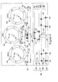
- Figure 7 illustrates how the three-dimensional colorspace is adjusted when the user moves the center of the mids color adjustment pad 420 to the right by an amount ⁇ X.
- the mids luminance plane 720 is moved over by the amount ⁇ X specified by the user.
- the other luminance level planes are adjusted in the same direction by an amount specified by a combination of ⁇ X and curve 750.
- curve 750 is defined as a well-known Bezier's curve. Note that the luminance axis Y is now curved.
- the movements of the three different color adjustment pads 430, 420, and 410 may be combined to create different colorspace adjustments.
- the user may first adjust the whites luminance level plane 530 to right by ⁇ X using the whites color adjustment pad 430 to produce the adjusted colorspace illustrated in Figure 6a .
- the user may then subsequently adjust the mids luminance plane 520 using the mids color adjustment pad 420.
- Figure 8 illustrates how the three-dimensional colorspace is appears after the user moves the center of the mids color adjustment pad 420 to the right by an amount of ⁇ X'. Note that the mids luminance level plan 892 has been shifted by ⁇ X' but whites luminance level plane 893 and the blacks luminance level plane 891 remain stationary. However, all the other luminance planes are adjusted according to curve 895. Additional details on one implementation of the math behind these color adjustments will be presented later in this document.
- the graphical user interface further includes three luminance adjustment sliders 439, 429, and 419 associated with each of the three luminance planes illustrated in Figure 5 .
- Figure 4 illustrates whites luminance slider 439, mids luminance slider 429, and blacks luminance slider 419.
- the luminance adjustment sliders 439, 429, and 419 adjust the luminance levels of pixels on luminance plane 530, 520, and 510, respectively.
- the luminance sliders adjust the luminance on their respective luminance planes.
- the whites luminance slider 439 adjusts the luminance for the pixels on the whites luminance plane 530 and the remaining luminance planes as a function of how close those other planes are to the whites luminance plane as illustrated by the input (x)/output (y) graphs in Figure 13 .
- moving the whites luminance adjustment slider 439 to the right increases the luminance of high luminance pixels as illustrated in Figure 14(c) .
- moving the whites luminance adjustment slider 439 to the left lowers the luminance of high luminance pixels as illustrated in Figure 14(d) . Leaving the whites luminance adjustment slider 439 in the center leaves the high luminance pixels unchanged.
- the blacks luminance slider 419 adjusts the luminance for the pixels on the blacks luminance plane 510 and the remaining luminance planes proportionally. Specifically, adjusting the blacks luminance slider 419 to the left decreases the luminance as illustrated by the input(x)/output(y) graphs of Figure 14(a) and adjusting the blacks luminance slider 419 to the right increases the luminance as illustrated in Figure 14(b) .
- the mids luminance slider 429 adjusts the luminance of pixels on the mids luminance plane 520.
- the adjustment to the mids luminance slider adjusts the other luminance planes in a curved manner according to a curve as illustrated in Figures 14(e) and 14(f) .
- moving the mids luminance slider 429 to the right raises the luminance of the mids as illustrated in Figure 14(e) and 14(g) and moving the mids luminance slider 429 to the left lowers the luminance of the mids as illustrated in Figure 14(g) .
- the auto-contrast buttons 460 are used to analyze a frame of the image being manipulated and then automatically adjust the luminance of the image. Specifically, the auto-contrast buttons 460 automatically adjust the blacks luminance slider 419 and whites luminance slider 439 to values which will expand or contract the luma values in the original images to fall into the maximum CCIR-recommended luma ranges (16 and 235).
- the specific auto-contrast buttons from left to right are: auto-black-level, auto-contrast, auto-white-level.
- the Auto-black-Level button will adjust the blacks slider to make the lowest input luma value map to CCIR-black (16).
- the Auto-White-Level button will adjust the highest input luma value to map to a user-specified white value. This user-specified white value is normally CCIR-white (235).
- the auto-contrast button performs both operations (auto-black-level and auto-white-level) in one step.
- buttons 460 are highly desirable since one of the tasks that professional colorists often perform is to adjust the black and white levels to see what contrast the original image has. After seeing the contrast in the original image, the colorist may increase (or decrease) the image's contrast as appropriate.
- a saturation adjustment slider 450 can be used to adjust the saturation of all the pixels.
- the saturation adjustment slider 450 adjusts the saturation of the effected pixels by multiplying each pixel's current saturation value with a saturation multiplier value between zero and two.
- Adjusting the saturation with a saturation multiplier value of zero would change all the pixels to zero saturation, resulting in a Black and white image. Adjusting the saturation with a saturation multiplier value of two would double the saturation of each pixel. Leaving the saturation adjustment slider 450 in the center position multiplies the saturation by a value of one and thus does not change the saturation of the pixels.
- the user may define a limited three-dimensional space within the three-dimensional colorspace that should be adjusted.
- the "limit effect" panel 460 at the bottom of the graphical user interface allows the user to specify a limited volume within the colorspace by selecting a particular hue range, saturation range, and luminance (luma) range. Limiting the effected pixels is also known as "keying.”
- Three-dimensional space 150 is defined with a ⁇ y luminance range, a ⁇ s saturation range, and a ⁇ h hue angle range. Not all three parameters need to be specified. If a particular parameter is not specified, then the entire range of that parameter will be adjusted with the color corrections. If no parameter is specified, then all the pixels will be affected.
- a user may specify a ⁇ h hue angle range by marking the hue angle range checkbox 478 (which indicates that the ⁇ h hue angle range should be considered) and defining a hue angle range on the hue spectrum 470.
- the ⁇ h hue angle range is specified along a hue spectrum 470 using a pair of defining hue markers 471 and 472.
- the angle determined by the defining hue markers 471 and 472 is used to allow the user to generate a smooth falloff for the color effect. For colors completely inside the defining hue markers 471 and 472, the effect is applied 100%. For colors completely outside the defining hue markers 471 and 472, the effect is not applied. For colors that fall into the "falloff area" which the user specifies by the angle of the defining hue markers 471 and 472, the resulting pixel is calculated by blending the original, unmodified pixel with the pixel after the effect has been applied. The effect is proportional to where the original pixel color is in the falloff area.
- the angled defining hue markers 471 and 472 allows for a smooth gradation between pixels subject to the effect and pixels not subject to the effect.
- hue angle reset button 477 to reset the defined hue angle to a default hue angle.
- the default hue angle is -110° with a default width of 15° and a default softness of 10.
- the user may center the hue spectrum 470 on a particular hue by selecting a hue from the image using eyedropper button 474.
- a user may specify a ⁇ s saturation range by marking the saturation range checkbox 488 and defining a saturation range on the saturation scale 480.
- the ⁇ s saturation range is specified along the saturation scale 480 using a pair of defining saturation markers 481 and 482.
- the angle determined by the defining saturation markers 481 and 482 is used to allow the user to generate a smooth falloff for the color correction.
- the user may press saturation range reset button 487 to reset the defined saturation range to a default saturation range.
- the default saturation range starts at 35% with a width of 40 and a softness of 20.
- the user may center the saturation markers 481 and 482 around a particular pixel's saturation value by selecting a pixel from the image using eyedropper button 474.
- a user may specify a ⁇ y luminance range by marking the luminance range checkbox 498 and defining a luminance range on the luminance scale 490.
- the ⁇ y luminance range is specified along the luminance scale 490 using a pair of defining luminance markers 491 and 492, As set forth with reference to the defining hue markers 471 and 472, the angle determined by the defining luminance markers 491 and 492 is used to allow the user to generate a smooth falloff for the color correction.
- the user may press luminance range reset button 497 to reset the defined luminance range to a default luminance range.
- the default luminance range starts at 0% with a width of 40 and a softness of 20.
- the user may center the luminance markers 491 and 492 around a particular pixel's luminance value by selecting a pixel from the image using eyedropper button 474. Furthermore, if the user activates the eyedropper while holding the shift key down then the hue, saturation, or luminance on which the user clicks will be added to the keying selection.
- the graphical user interface for the color correction window may be implemented in many different manners.
- the different color correction graphical user interface embodiments may include new features and omit other features.
- Figure 9 illustrates a first alternate embodiment of a color correction user interface.
- the whites luminance plane 630 may be adjusted as illustrated in Figure 6(a) .
- the embodiment of Figure 9 includes all three luminance adjustment sliders 939, 929, and 919 such that the luminance levels of all three different luminance planes 530, 520, and 510 may be adjusted accordingly.
- the color correction embodiment of Figure 9 introduces a new color adjustment device, the hue adjustment wheel 920.
- the hue adjustment wheel 920 allows the user to simultaneous adjust the hues of all the pixels (defined by the limit effect panel) by rotating the colorspace. Specifically, a user may rotate the outer wheel 921 to rotate the hue spectrum. This causes the entire colorspace to be rotated by a corresponding amount as illustrated by the arrow 521 in Figure 5 , This type of color change is sometimes known as a hue phase shift. To reset any hue phase shift changes, the user may activate the hue rotation reset button 527 to move the hues back to their original (default) position.
- Figure 10 illustrates a second alternate embodiment of a color correction user interface.
- the color correction user interface of Figure 10 is very powerful since it contains all the features of the previous two user interfaces, but the color correction user interface of Figure 10 is slightly cluttered.
- the present invention provides for color correction in a novel manner by performing the color correction and keying in the YUV colorspace in order to reduce processing cycles and to save time through the avoidance of rendering. This is in marked contrast to prior art techniques that perform color correction in the RGB space and, thus, tend to involve greater amounts of rendering. By reducing or removing the time consuming rendering steps, the system of present invention is more efficient than prior art systems.
- the inventive techniques utilize look-up tables (LUTs) that may convert user inputted color corrections to the YUV or YCrCb colorspace in selected images to an outputted value.
- LUTs look-up tables
- YUV and YCrCb denote different values mathematically, for purposes of the present invention, YUV and YCrCb are deemed interchangeable as used herein.
- the look-up tables (LUTs) that provide for the remapping of pixels according to the user's desired color correction are used to provide a high performance pixel remapping.
- the color correction pixel remapping performed by the present invention may be implemented in other manners.
- the color correction graphical user interface of Figure 10 includes user interface devices for adjustment of color space shifting, hue phase shift, luminance levels, and saturation.
- Figure 11 illustrates a flow diagram containing, a segment of the inventive technique in one embodiment.
- User input representing the desired color correction is received at 1110 for a given color space.
- the user input may be provided using of the graphical user interfaces depicted in Figures 4 , 9 , or 1 0 .
- the user input from the color adjustment pads may be in the form of a vector that is converted at 1120 to Cartesian coordinates for computational purposes. In another embodiment, however, it is possible to have the user input directly in the form of Cartesian coordinates, without the use of vectors.
- LUTs look-up tables
- the details of which will be discussed in greater detail below are discussed in greater detail below. Note that in certain applications, however, it may not be necessary to recomputed one or more LUTs, given that it is possible that a user may only modify a parameter that does not require a look-up table recomputation such as a saturation adjustment.
- the color information of designated pixels are remapped at step 1140. In one embodiment, the YCrCb values that define the designated pixels are remapped with the aid of the recomputed from the look-up tables (LUTs).
- Figure 12 illustrates a flow diagram describing the pixel remapping referred to in step 1140 of Figure 11 .
- the pixel color correction may begin by receiving a pixel at step 1210.
- an adjustment to the pixel's luminance is made at step 1220 based on the luminance look-up tables (LUTs), as described in greater detail hereafter.
- the previously described luminance adjustment sliders are able to provide user control of the luminance (Y) value of a YCrCb defined pixel.
- an adjustment to the chrominance is made at 1230 based on the chrominance look-up tables (LUTs) that have been modified based on user input from the color adjustment pads as previously disclosed.
- the chrominance adjustment is relative to the initial chrominance value.
- the previously described color adjustment pads are able to provide user control of the chrominance (Cr and Cb) values of a YCrCb defined pixel.
- the color correction user interface may include a hue adjustment wheel that may rotate the hues of pixels.
- the hue rotation may be expressed as a phase shift h .
- a final assignment of chrominance is made, based on any existing phase shift h , at step 1240.
- the phase shifted chrominance values are determined from the previous chrominance values and the phase shift h .
- a final adjustment is made to a pixel's Cr and Cb values at step 1250, based on a saturation adjustment s .
- the saturation adjustment s (or satadjust) may increase or decrease the amount of color depending on user input using the saturation adjustment slider. This increase or decrease is accomplished by setting the saturation adjustment s to a value between 0 and 2 inclusive and then multiplying the above final color correction results by the factor of s to get the final adjusted color correction.
- Steps 1210 through 1250 are then repeated until the last pixel from the designated image(s) has been remapped, as determined at 1260.
- the first pixel adjustment in one embodiment of the present invention is to adjust the pixel's luminance (Y) value.
- the adjusted luminance value is based on the pixel's current luminance value and input from the user on the luminance sliders in the graphical user interface.
- the user input is used to adjust a luminance look up table that will be used to modify the luminance of each affected pixel.
- Figure 13 illustrates a graphical representation of the potential transitions for the relationship between the different pixel luminance input values on the input ( x ) axis 1305 versus the respective pixel luminance output values on the output ( y ) axis 1310.
- a user may adjust the luminance adjustment sliders in order to modify luminance control values W, M, and B .
- changes to in the luminance control values W, M, and B adjust the input/output graph as set forth in Figure 13 .
- changes to the W luminance control value may adjusts the input/output graph in the directions indicated at 1320
- changes to the M luminance control value may adjust the input/output graph in the directions indicated at 1330
- changes to the B luminance control value may adjust the input/output graph in the directions indicated at 1340.
- Figures 14(a) to 14(g) illustrate more specific examples which are controlled for movement of individual variables in accordance with the previously described user interface. Specifically: Figure 14(a) illustrates the resulting input/output graph where the B value has been made darker, as seen by the movement of the B from the origin point out along the x axis; Figure 14(b) illustrates the resulting input/output graph where the B value has been made lighter, as seen by the movement of the B from the origin point out along the y axis; Figure 14(c) illustrates the resulting input/output graph where the W value has been made lighter, as seen by the movement of the W back along the x axis; Figure 14(d) illustrates the resulting input/output graph where the White W value has been made darker, as seen by the movement of the W down along the y axis; Figure 14(e) illustrates the resulting curved input/output graph where the M value has been lifted up, as seen by the movement of the M in an upward direction; Figure 14(f) illustrate
- Figure 14(g) details, for one embodiment, the usage of an exemplary Bezier curve 1490 and the control points k0 1410, k1 1460, k2 1480 and k3 1440 of the Bezier curve function which are used to compute the non-linear input/output relationship on the look-up table which correlate to M control modifications. More specifically, the Bezier control points k0 1410, k1 1460, k2 1480 and k3 1440 for the luminance map are set up based on the endpoints and the previously described M adjustment slider.
- the curve for the M control is calculated using Bezier control points k0 1410 , k1 1460 , k2 1480 and k3 1440 .
- the endpoints k0 1410 and k3 1440 for the Bezier curve are calculated the same way as they would be for a linear case, as shown in Figures 14(a) to 14(d) , and are derived solely from the blacks luminance slider 419 and whites luminance slider 439 of Figure 4 .
- MidPt 1430, Corner 1450, and CtlPt 1470 are all intermediate values used to illustrate how k1 1460 and k2 1480 are derived from k0 1410, k3 1440, and the previously described M adjustment slider, the middle Bezier control points (k1 1460, k2 1480 ) are calculated as follows.
- k1 1460 a calculation is made to determine k1 1460, by interpolating between k0 1410 and CtlPt 1470, again using the above-described weighting factor: k ⁇ 1.
- ⁇ h 0.5 + 1.0 - weight 2 * CtlPt . h + 1.0 - 0.5 + 1.0 - weight 2 * k ⁇ 0. ⁇ h
- k1.v a similar expression
- k2 k ⁇ 1.
- ⁇ h 0.5 + 1.0 - weight 2 * CtlPt . h + 1.0 - 0.5 + 1.0 - weight 2 * k ⁇ 3.
- ⁇ h A similar expression may be employed to obtain k2.v.
- Figure 14(g) illustrates where these points would lie relative to k0 1410 and k3 1440 for M> 100.
- M and therefore the above described "weight”
- CtlPt will be interpolated to different locations along the line between Corner 1450 and MidPt 1430.
- k1 1460 and k2 1480 will be interpolated to different positions on the lines between k0 1410 and CtlPt 1470 and between k3 1440 and CtlPt 1470.
- the arrows at k1 1460 , CtlPt 1470, and k2 1480 suggest how these points move as the mids ( M ) luminance slider is adjusted (in the range 100-200).
- the second adjustment in one embodiment of the present invention is a pixel chrominance adjustment based on input from the user on the color adjustment pads. Adjustments to the color adjustment pads skew the three-dimensional color space such that the chrominance value for each pixel must be changed.
- Figure 6(b) illustrates how the three-dimensional colorspace is adjusted when the user moves the center of the blacks color adjustment pad 410 to the right by an amount ⁇ X.
- the effect of an adjustment of ⁇ X to the whites (W) luminance plane or blacks (B) luminance plane on the mids (M) luminance plane would be that of ⁇ ⁇ x 2 for a movement of ⁇ x by W or B, as depicted in Figures 6(a) and 6(b) .
- An adjustment to the mids (M) luminance plane would affect the cylindrical representation along the Bezier shaped luminance axis (Y) as broadly depicted in Figure 7 , and as will be more fully detailed in the below exemplary applications.
- the user's input may be received as an angle and magnitude defined vector.
- the angle and magnitude defined vector is then translated into a relative U,V vector for that luminance plane.
- a vector input for the white color adjustment pad would be translated into a Cartesian vector with a U W value specifying a relative move along the U-axis and a V W value specifying a relative move along the V-axis.
- all of the relative Cartesian vector values U W ,V W , U M , V M , U B ,V B are zero.
- Figure 16 illustrates another example of the cylindrical colorspace representation where the white (W), mid (M), and black (B) luminance planes have all been shifted such that each has been pushed an equal amount to reflect different amounts of Cb and Cr values.
- Cb has been pushed by-0.30 and Cr has been is pushed by 0.10.
- Figure 17 illustrates a more complex example of adjusting the cylindrical colorspace representation where the white, mid, and black luminance planes are being pushed differently.
- a Bezier curve is used to interpolate the adjustments for the luminance planes in between the white, mid, and black luminance planes.
- this implementation uses a Bezier function to generate a curve that users have found to be appropriate for the given color correction, other functions that generate similar curves and even other curves may also be used.
- Figure 18 illustrates a graph 1894 created from two Bezier curves connected by a linear segment (between 1890 and 1880), with theoretical control points (1810, 1820, 1890, and 1892) and (1880, 1870, 1840, and 1850).
- a more specific instantiation may be arrived at such as in Figure 19 , where the graph created from two Bezier curves and the linear segment is termed "gMidRamp".
- the gMidRamp is used to generate look up table for Cb, (CbLUT) as illustrated in Figure 20 and a look-up table for Cr (not shown).
- the lookup table size is assumed to be 256; (2) the lookup table is pre-initialized below 55 with 0 and above 164 with 0; (3) the lookup table is pre-initialized between 55 and 164 with 1.0; (4) the Bezier curves are placed with a left endpoint (0,0) at array index 4 (1810) and right endpoint (1.0, 1.0) at array index 104 (1890), and control points of (0.25, 0.0) (1820) and (0.75, 1.0) (1892), as shown at left side of Figure 18 ; and ( 5 ) the curves are further placed with a left endpoint (0.0, 1.0) at array index 114 and a right endpoint (1.0, 0.0) at array index 214 (1850), and control points of (0.25, 1.0) (1880) and (0.75, 0.0) (1840), as at right.
- the circles are control pts k0, k1, k2, k3, and k0, k1, k2, k3.
- the graph starts at 0, and tick marks represent 50% luma (114.5) and CCIR-white (219) (1860).
- the relative Cartesian vectors (U w , V w ) and ( U B , V B ) are generated directly from the user's inputs to the white and black color adjustment pads.
- the Cartesian vector for the mids (M) luminance plane is a combination of the user input for the blacks and whites luminance planes along with the user's direct input for the mids luminance plane.
- Figure 21 illustrates another example of a modified cylindrical colorspace representation.
- the modified the cylindrical colorspace representation of Figure 21 both the mids and the white luminance planes have been pushed.
- the same techniques are used to create the chrominance look-up tables (CbLUT and CrLUT). Note the same gMidRamp function is used.
- keying may be employed to limit the effect of color correction.
- Figure 24 illustrates a broad description of the inventive color correction system according to the recomputation of YUV values by usage of look up tables as described for a keyed area.
- the first step and differentiating step from the process outlined in Figure 11 involves identifying a keyed color region.
- the techniques of keying may be used to identify or designate an entire image or images, as well as specific portions thereof, or even may be applied to specific object or backgrounds, as known in the art of keying.
- the key may be partial (semi transparent) in which case the color corrected result is mixed with the uncorrected (original) pixel, allowing for a smooth transition between corrected and uncorrected areas of the images when using the Limit Effect panel.
- keying is performed using the limit effect panel 460 of Figure 4 .
- Figure 25 illustrates an overall description of the pixel remapping of the inventive color correction described in Figure 12 but only over the keyed pixels. As indicated, the differentiating step for keying over a designated area occur at 2515, where an assessment is made as to whether a pixel having color value YCrCb is in a keyed area.
Abstract

Description
- The present invention relates to the field of digital image processing. In particular, the present invention discloses a graphical user interface and methods for performing color correction and color keying.
- Recent advances in video processing technologies have led to a surge in popularity of new video processing applications that make powerful video editing capabilities available to a wide base of users. Typically, video processing applications allow users to download and upload video and audio segments, as well as edit and manipulate these segments for producing a cohesive video or movie.
- In performing such tasks, video processing applications often use a video capture card to capture and store video segments onto the hard drive of a computer system. Video capture cards typically employ a coder/decoder (also called a "CODEC") to compress the video with a compression standard such as Motion-JPEG, DV, MPEG-1, MPEG-2, etc. Many digital video storage formats store pixel data in a luminance and chrominance colorspace often referred to Y/Cr/Cb (also referred to as YUV). In a luminance and chrominance colorspace three components are stored for each pixel: one for luminance (Y) and two for color information (Cr and Cb). Most computer display systems store pixel information in an RGB format that also contains three components per pixel, one each for the Red (R), Green (G), and Blue (B) portions of the color. Pixel information stored in either YUV or RGB format can be converted to the other format using straightforward matrix mathematics.
- In the DV (digital video) storage format, storage is typically accomplished with an 8-bit luminance (Y) value for each pixel. 8 bits allows luminance (Y) values ranging from 0 through 255. In 8-bit digital video, black is typically encoded at Y = 16 and white is encoded at Y = 235. The luminance values from 1 to 15, referred to as footroom, and 236 to 254, referred to as headroom, are used to accommodate ringing and overshoot in a signal. Industry standard equations (such as those specified by Rec. ITU R BT-601) can convert 8-bit RGB encoded images with RGB values ranging from 0 to 255 into YUV encoded images with luminance (Y) values ranging from 16 to 235. Most software DV CODECs follow this mapping so that a use may translate, say, naturalisitic computer pictures into quality video.
- However, there are several phenomena which may contribute to degradation or compromising of the dynamic range of given colors in a resulting video segment. For example, difficulties often arise, for example, because cameras can often capture values that are superwhite (values resulting from specular reflections, sun, or bright lights, clouds or white walls). Superwhite values may exceed the nominal white value of 235 as registered on a waveform monitor, where these whites may peak at 100 IRE (NTSC) which is the brightest value allowable on a broadcast RF modulator. In the YUV space, the Y values range from 235 to 254; but on a waveform monitor, whites can be seen to range from 100 IRE to almost 110 IRE, all of which represent illegal values (e.g., Y values above 254), and are accordingly clipped to 254 by a CODEC when converting to RGB, thereby compromising the dynamic range of at least the white value in a given digital image.
- Typically, users may attempt to mitigate such value degradation by employing color correction of the RGB space. A problem arises, however, because color correction, still yield only a limited amount of headroom for colors (such as superwhite), and also require extensive operations cycles, execution time, and memory access in computer systems that support digital video processing applications. Inherent in such a problem is the need for rendering, where editing is translated and stored on the hard drive a computer system supporting a given video image processing application. Even recently developed "real time" systems still need to go back to rendering in cases where a user simultaneously color corrects, adds filters, effects, and superimposes graphics, even for a high end real time system, the capacity will be overwhelmed and the real time performance will be compromised. As such, there are still deficiencies not addressed by recent advances in video processing, which in particular concerns the limited overhead on color values and a less expensive approach to color correction.
- A graphical user interface for performing color correction and methods for implementing the color correction are disclosed. The graphical user interface ·allows a user to adjust the colorspace of the pixels in the image. In one embodiment, a color adjustment pad allows the user to push the pixels from a particular luminance level a desired magnitude towards a desired hue. Pixels from other luminance levels are affected proportionally. The graphical user interface further allows a user to adjust the luminance of the pixels in the image. A luminance adjustment slider allows the user to adjust the luminance of pixels from a selected luminance level by a relative amount. Pixels from other luminance levels have their luminance are affected in a manner proportional to a difference between the selected luminance level value and the luminance value of the other pixel.
- Other objects, features, and advantages of present invention will be apparent from the company drawings and from the following detailed description.
- The objects, features, and advantages of the present invention will be apparent to one skilled in the art, in view of the following detailed description in which:
-
Figure 1(a) illustrates a conceptual diagram of a three-dimensional colorspace defined in the luminance (Y) and chrominance (UV) format known as a YUV format. -
Figure 1(b) illustrates a conceptual diagram of a three-dimensional colorspace ofFigure 1(a) defined in an alternate hue (H), saturation (S), and luminance (Y) format. -
Figure 2 illustrates one embodiment of a graphical user interface for a color correction control system of the present invention. -
Figure 3(a) illustrates a compliant video frame in the canvas window. -
Figure 3(b) illustrates a subsequent video frame in the canvas window with all the pixels close to an allowable maximum highlighted with zebra striping. -
Figure 3(c) illustrates a subsequent video frame in the canvas window with all the pixels close to an allowable maximum highlighted with a first zebra striping and all the pixels exceeding the allowable maximum highlighted with a second zebra striping. -
Figure 4 illustrates one embodiment of a graphical user interface for thecolor correction window 230 of the color correction control system inFigure 2 . -
Figure 5 illustrates a white luminance plane, a mids luminance plane, and a blacks luminance plane in the colorspace ofFigures 1(a) and 1(b) . -
Figures 6(a) illustrates the effect of moving the white luminance plane of the cylindrical colorspace representation to the right. -
Figures 6(b) illustrates the effect of moving the black luminance plane of the cylindrical colorspace representation to the right. -
Figure 7 illustrates the effect of moving the mids luminance plane on the cylindrical colorspace representation to the right. -
Figure 8 illustrates the effect of moving the mids luminance plane to the right on a cylindrical colorspace already modified as illustrated inFigure 6(a) . -
Figure 9 illustrates a first alternate embodiment of a graphical user interface for thecolor correction window 230 of the color correction control system inFigure 2 . -
Figure 10 illustrates a second alternate embodiment of a graphical user interface for thecolor correction window 230 of the color correction control system inFigure 2 . -
Figure 11 illustrates a flow diagram of one color correction implementation that performs color correction using look-up tables recomputed based upon user input from a graphical user interface. -
Figure 12 illustrates a flow diagram describing pixel remapping using the color correction system of the present invention. -
Figure 13 illustrates a graphical representation of an exemplary range of potential transitions for the different pixel luminance input versus pixel luminance output relationships within a lookup table for luminance correction. -
Figures 14(a) to 14(g) illustrates graphical representations of the various input versus output relationships within a lookup table for luminance correction within the inventive system, as well as the control points of the Bezier curve which describes the M control modifications within the look-up table. -
Figure 15 illustrates an unmodified cylindrical colorspace representation where the white (W), mid (M), and black (B) luminance planes are all physically centered on the Cb = 0, Cr = 0 axis, and where none of the values UW,VW,UM,VM,Ub,Vb have been modified. -
Figure 16 illustrates a cylindrical colorspace representation where the white (W), mid (M), and black (B) luminance planes have been pushed an equal amount to reflect changed Cb and Cr values regardless of luminance. -
Figure 17 illustrates a cylindrical colorspace representation where the white (W), mid (M), and black (B) luminance planes have been pushed such that Cb has been pushed negative at M, but B and W remain the same. -
Figure 18 illustrates the abstract control points that form the basis for an exemplary Bezier curve function called "gMidRamp". -
Figure 19 illustrates the gMidRamp function that can be used to calculate a look up table for Cb and Cr across the various luminance levels. -
Figure 20 illustrates the look up table that provides a Cb offset amount for a given luminance input, as a result of the application of the gMidRamp function to the modified colorspace ofFigure 17 . -
Figure 21 illustrates another example of a modified cylindrical colorspace representation where Cb and Cr have been pushed at M and W, but B remains the same. -
Figure 22 illustrates the look up table that provides an offset amount for a given luminance input, as a result of the application of the gMidRamp function to the Cb example taken from the specific example inFig. 21 . -
Figure 23 illustrates the look up table that provides an offset amount for a given luminance input, as a result of the application of the gMidRamp function to the Cr example taken from the specific example inFig. 21 . -
Figure 24 is a flow diagram illustrating a broad description of the color correction according to the recomputation of YUV values by usage of look up tables in the inventive technique for keyed pixels. -
Figure 25 is a flow diagram illustrating an overall description of the pixel remapping of the inventive color correction over keyed pixels. - A method and user interface for performing color correction is disclosed. In the following description, for purposes of explanation, specific nomenclature is set forth to provide a thorough understanding of the present invention. However, it will be apparent to one skilled in the art that these specific details are not required in order to practice the present invention. For example, the present invention has been described with reference to Bezier curves. However, the same techniques can easily be applied with other types of curved functions.
- Digital video pixel information is commonly stored in a three component luminance and chrominance format. For example, both the MPEG-1 and MPEG-2 digital video standards encode pixel data with three component luminance and chrominance format.
- The luminance specifies the brightness of a pixel. Luminance ranges from pure black to pure white. Luminance is typically expressed in a single component Y value. The chrominance specifies the color of a pixel and is stored as two component values Cr and Cb (that are also referred to as U and V values). One reason that digital video is stored in a luminance and chrominance format is that human vision is much more sensitive to luminance information than chrominance information such that separate chrominance information can be more heavily compressed without significantly detectable image degradation.
- Computer display systems generally represent pixel information in a three component RGB format wherein the three components specify the amount of Red (R), Green (G), and Blue (B) required to represent a pixel. Pixel information stored in either RGB format or YUV format can easily be converted to the other format using simple matrix math.
-
Figure 1(a) illustrates a conceptual diagram of a three-dimensional colorspace defined in the luminance (Y) and chrominance (UV) YUV format. The two part UV chrominance value is not intuitive to humans. Thus, the colorspace often defined in an alternative hue (H), saturation (S), and luminance (Y) format. -
Figure 1(b) illustrates an alternate interpretation of the three-dimensional colorspace inFigure 1(a) . The colorspace ofFigure 1(b) is defined in terms of luminance (Y), hue (H), and saturation (S). - The luminance (Y) value continues to represent the brightness of a pixel. Luminance (Y) is represented as a vertical coordinate along the vertical axis of the cylinder of the cylindrical colorspace of
Figure 1(b) . - The hue (H) represents a particular color value. Hue is represented as an angle from the center of the cylinder of the cylindrical colorspace of
Figure 1(b) . Hue is often specified on a common color wheel. - Saturation (S) refers to the depth or intensity of a pixel's color (hue). In other words, how strong the color is relative to an unsaturated white/gray/black of the same luminance level. For example, a deep red has a high level of saturation (mostly pure red with little white) and a pinkish red is only lightly saturated (less pure red and a higher level of white). Saturation is represented in the colorspace of
Figure 1(b) as a distance along a vector defined by the hue (H) angle. - Film and television feature productions generally go through three phases: pre-production, production, and post-production. The pre-production phase is when the script is created, the actors are cast, and the sets are built. During production phase, the actual film is shot or the videotape is recorded using the actors and sets. Finally, during the post-production, the film or video tapes is edited together, the sound is edited, music is added, special effects are added, and the film or video tape images are adjusted.
- As part of the post-production process, the images from many films and television shows go through a process of "color correction." The process of color correction is used to fix color problems that occur during the filming or videotape production.
- Professional colorists refer to primary, secondary, and tertiary color correction. Primary color correction involves fixing the basic color balance of an image to make it look correct with true color representation. Primary color correction problems include incorrect color casting from bad lighting, color problems caused by color filters, and improper exposure. Secondary color correction problems are cause by mismatched colors for related scenes shot at different times or with different lighting.
- Tertiary color correction is actually color enhancement such as making a scene darker to enhance a particular mood. Tertiary color correction is also used to perform certain special effects. For example, the director or editor may wish to change the color of specific objects in a scene. For example, the director or editor may change the color of clothing worn by a particular character. The director may change the eye color of characters such as the distinctive blue eyes in the feature film "Dune."
- The present invention introduces a new color correction system that allows post-production specialists to have wide latitude of control over the colors in series of images. The color correction system uses a highly intuitive graphical user interface such that post-production specialists can quickly learn the color correction system and professionally apply its features.
-
Figure 2 illustrates one embodiment of a graphical user interface for a color correction control system of the present invention. In the graphical user interface ofFigure 2 , there are three different windows for presenting information. - A
first window 210 is a "canvas" window that displays the video or other images that are being adjusted with the color correction system. In a preferred embodiment, thecanvas window 210 includes novel feedback systems that provide more information than just the image. - Images may contain pixels that exceed a maximum luminance value allowed for broadcast material. Thus, it would be desirable to be able to identify and locate pixels that exceed this maximum allowed luminance value. In one embodiment, the
canvas window 210 can be placed into a luminance test mode. When in the luminance test mode, the color correction system tests the all the pixels in an image to determine if the luminance of each pixel is close to or above an acceptable luminance threshold value. An example of luminance test mode will be described with reference toFigures 3(a) to 3(c) . -
Figures 3(a) illustrates a canvaswindow video frame 310 that is tracking a ski jumper that will soon pass by thesun 320 that is currently not in the video frame. The sun emits so much light that it can easily cause image pixels having luminance values that are out of range. Referring toFigure 3(a) , since the skier is not yet close enough to the sun, all the pixels are currently within the luminance limit. Thus, when all the pixels are within the maximum luminance value, the canvaswindow video frame 310 may simply display an indication such as the "OK"indication 350 that indicates that the image is compliant with the luminance restrictions. - Referring to
Figure 3(b) , as the skier comes closer to the sun, some of the pixels in a halo around the sun come very close to the maximum luminance value allowed for broadcast material. In one embodiment, "very close" is defined as within 10% maximum luminance value allowed for broadcast material. To warn the user about this, the luminance test mode displays awarning indication 360 in the canvaswindow video frame 310. Furthermore, the luminance test mode highlights thepixels 331 very close to the maximum luminance value. In one embodiment, the pixels are "zebra striped" with green stripes. Note that the zebra striping allows the underlying image to remain visible. - Finally, referring to
Figure 3(c) , the skier is close to the sun such that some of the pixels from a halo around the sun come exceed the maximum luminance value allowed for broadcast material. To alert the user about the "illegal" pixels, the luminance test mode displays aviolation indication 370 in the canvaswindow video frame 310. Furthermore, the luminance test mode highlights thepixels 332 very close to the maximum luminance value and thenoncompliant pixels 342 that exceed the maximum luminance value. In one embodiment, the pixels close to the maximum luminance value are zebra striped with green stripes and the pixels exceeding the maximum luminance value are zebra striped with red stripes. - In alternate embodiments, the luminance test mode may display pixels "close" (within 20%) with green zebra striping, "very close" (within 10%) with yellow zebra striping, and exceeding the maximum luminance value with red zebra striping. Furthermore, in one embodiment the canvas window video frame implements a saturation test mode. When in the saturation test mode, the pixels that exceed the maximum allowed color stripes are highlighted with zebra striping. In a preferred embodiment, the user may activate the luminance test mode and the saturation test mode simultaneously such that the user can locate over saturated pixels and pixels that exceed the maximum allowed luminance value at the same time.
- A
second window 220 is a "workbench" window that displays a number of commonly used scopes for video editing. Theworkbench window 220 may include scopes such as a waveform monitor, a vectorscope, and a luminosity histogram as is well known in the art. Other useful graphs may be created or subsequently added at a later date. The combination of thecanvas window 210 and theworkbench window 220 provide feedback to the user. - The
third window 230 is a color correction interface window that contains tools for performing color correction. The colorcorrection interface window 230 comprises a graphical user interface containing several different color correction tools for performing color correction on the images in thecanvas window 210. The graphical user interface containing several different color correction tools for performing color correction and the methods that implement those color correction tools are one of the primary focuses of this document. -
Figure 4 illustrates one embodiment of a graphical user interface for thecolor correction window 230 of the present invention. Other embodiments will be described but practicing the invention does not require implementing all the features of one particular embodiment. - In the
color correction window 230 embodiment ofFigure 4 , there are three differentcolor adjustment pads hatch mark color adjustment pads - The
color adjustment pads center - The three different
color adjustment pads Figure 5 . Specifically, whitescolor adjustment pad 430 corresponds towhites luminance plane 530, mids (middle)color adjustment pad 420 corresponds to a mids (middle)luminance plane 520, and blackscolor adjustment pad 410 corresponds toblacks luminance plane 510. The three differentcolor adjustment pads corresponding luminance plane - Each
color adjustment pad reset button - Each
color adjustment pad eyedropper button - When an adjustment is made for a particular luminance level, other luminance levels are affected as well. When the whites
color adjustment pad 430 or the blackscolor adjustment pad 410 is used to adjust the whites luminanceplane 530 or blacks luminanceplane 510, respectively, all the other luminance places are adjusted proportionally according to their distances from the adjusted luminance plane. In one embodiment, an adjustment to the whites luminanceplane 530 or blacks luminanceplane 510 causes the other luminance planes to be adjusted depending on how close those planes are to the adjusted luminance plane. When the midscolor adjustment pad 420 is used to adjust themids luminance plane 520, then the other luminance places are also adjusted. However, in one embodiment, an adjustment to themids luminance plane 520 causes the other luminance planes to be adjusted according to a curve depending on how close those planes are to the adjustedmids luminance plane 520. - Referring to
Figure 4 , if the user moves the center of the whitescolor adjustment pad 430 to the right, the pixels of the highluminance level plane 530 are adjusted toward the blue (B) hue and lower luminance level planes are adjusted proportionally. Specifically,Figure 6(a) illustrates how the three-dimensional colorspace is adjusted when the user moves the center of the whitescolor adjustment pad 430 to the right by an amount of ΔX. Note that themids luminance plane 620 is moved over half as much ((ΔX)/2) as the whitesluminance level plane 630 and that the blacksluminance level plane 610 is not adjusted at all. Note that the luminance axis Y now extends upward at an angle into the colorspace. - Similarly, if the user moves the center of the blacks
color adjustment pad 410 to the right, the pixels of the blacks luminance level plane are adjusted toward the blue (B) hue and higher luminance level planes are adjusted proportionally. Specifically,Figure 6(b) illustrates how the three-dimensional colorspace is adjusted when the user moves the center of the blackscolor adjustment pad 410 to the right by an about ΔX. Again, themids luminance plane 670 is moved over half as much ((ΔX)/2) as the blacks luminanceplane 660 and the whitesluminance level plane 680 remains stationary. - If the user moves the mids (middle)
color adjustment pad 420, the system moves colors of themids luminance plane 520 accordingly. The other luminance planes are also moved, but by an amount specified by a curve. Specifically,Figure 7 illustrates how the three-dimensional colorspace is adjusted when the user moves the center of the midscolor adjustment pad 420 to the right by an amount ΔX. As illustrated inFigure 7 , themids luminance plane 720 is moved over by the amount ΔX specified by the user. The other luminance level planes are adjusted in the same direction by an amount specified by a combination of ΔX andcurve 750. In one embodiment,curve 750 is defined as a well-known Bezier's curve. Note that the luminance axis Y is now curved. - The movements of the three different
color adjustment pads luminance level plane 530 to right by ΔX using the whitescolor adjustment pad 430 to produce the adjusted colorspace illustrated inFigure 6a . The user may then subsequently adjust themids luminance plane 520 using the midscolor adjustment pad 420.Figure 8 illustrates how the three-dimensional colorspace is appears after the user moves the center of the midscolor adjustment pad 420 to the right by an amount of ΔX'. Note that the midsluminance level plan 892 has been shifted by ΔX' but whites luminancelevel plane 893 and the blacksluminance level plane 891 remain stationary. However, all the other luminance planes are adjusted according tocurve 895. Additional details on one implementation of the math behind these color adjustments will be presented later in this document. - Referring back to
Figure 4 , the graphical user interface further includes threeluminance adjustment sliders Figure 5 . Specifically,Figure 4 illustrateswhites luminance slider 439,mids luminance slider 429, and blacks luminanceslider 419. Theluminance adjustment sliders luminance plane - As with the color adjustment pads, the luminance sliders adjust the luminance on their respective luminance planes. The whites luminance
slider 439 adjusts the luminance for the pixels on the whites luminanceplane 530 and the remaining luminance planes as a function of how close those other planes are to the whites luminance plane as illustrated by the input (x)/output (y) graphs inFigure 13 . Specifically, moving the whitesluminance adjustment slider 439 to the right increases the luminance of high luminance pixels as illustrated inFigure 14(c) . Similarly, moving the whitesluminance adjustment slider 439 to the left lowers the luminance of high luminance pixels as illustrated inFigure 14(d) . Leaving the whitesluminance adjustment slider 439 in the center leaves the high luminance pixels unchanged. - The blacks luminance
slider 419 adjusts the luminance for the pixels on the blacks luminanceplane 510 and the remaining luminance planes proportionally. Specifically, adjusting the blacks luminanceslider 419 to the left decreases the luminance as illustrated by the input(x)/output(y) graphs ofFigure 14(a) and adjusting the blacks luminanceslider 419 to the right increases the luminance as illustrated inFigure 14(b) . - The
mids luminance slider 429 adjusts the luminance of pixels on themids luminance plane 520. In one embodiment, the adjustment to the mids luminance slider adjusts the other luminance planes in a curved manner according to a curve as illustrated inFigures 14(e) and 14(f) . Specifically, moving themids luminance slider 429 to the right raises the luminance of the mids as illustrated inFigure 14(e) and14(g) and moving themids luminance slider 429 to the left lowers the luminance of the mids as illustrated inFigure 14(g) . - In the center of the graphical user interface of
Figure 4 is a set of auto-contrast buttons 460. The auto-contrast buttons 460 are used to analyze a frame of the image being manipulated and then automatically adjust the luminance of the image. Specifically, the auto-contrast buttons 460 automatically adjust the blacks luminanceslider 419 and whites luminanceslider 439 to values which will expand or contract the luma values in the original images to fall into the maximum CCIR-recommended luma ranges (16 and 235). - Referring to the auto-
contrast buttons 460 inFigure 4 , the specific auto-contrast buttons from left to right are: auto-black-level, auto-contrast, auto-white-level. The Auto-black-Level button will adjust the blacks slider to make the lowest input luma value map to CCIR-black (16). The Auto-White-Level button will adjust the highest input luma value to map to a user-specified white value. This user-specified white value is normally CCIR-white (235). The auto-contrast button performs both operations (auto-black-level and auto-white-level) in one step. - These auto-
contrast buttons 460 are highly desirable since one of the tasks that professional colorists often perform is to adjust the black and white levels to see what contrast the original image has. After seeing the contrast in the original image, the colorist may increase (or decrease) the image's contrast as appropriate. - Referring again to
Figure 4 , asaturation adjustment slider 450 can be used to adjust the saturation of all the pixels. Thesaturation adjustment slider 450 adjusts the saturation of the effected pixels by multiplying each pixel's current saturation value with a saturation multiplier value between zero and two. - Adjusting the saturation with a saturation multiplier value of zero would change all the pixels to zero saturation, resulting in a Black and white image. Adjusting the saturation with a saturation multiplier value of two would double the saturation of each pixel. Leaving the
saturation adjustment slider 450 in the center position multiplies the saturation by a value of one and thus does not change the saturation of the pixels. - To limit the effects of color correction, the user may define a limited three-dimensional space within the three-dimensional colorspace that should be adjusted. Referring to
Figure 4 , the "limit effect"panel 460 at the bottom of the graphical user interface allows the user to specify a limited volume within the colorspace by selecting a particular hue range, saturation range, and luminance (luma) range. Limiting the effected pixels is also known as "keying." - Referring back to the colorspace illustration of
Figure 1(b) , an example of a defined three-dimensional space 150 within the three-dimensional colorspace is illustrated. Three-dimensional space 150 is defined with a Δy luminance range, a Δs saturation range, and a Δh hue angle range. Not all three parameters need to be specified. If a particular parameter is not specified, then the entire range of that parameter will be adjusted with the color corrections. If no parameter is specified, then all the pixels will be affected. - Referring back to the
limit effect panel 460 ofFigure 4 , a user may specify a Δh hue angle range by marking the hue angle range checkbox 478 (which indicates that the Δh hue angle range should be considered) and defining a hue angle range on thehue spectrum 470. The Δh hue angle range is specified along ahue spectrum 470 using a pair of defininghue markers - The angle determined by the defining
hue markers hue markers hue markers hue markers hue markers - The user may press hue
angle reset button 477 to reset the defined hue angle to a default hue angle. In one embodiment, the default hue angle is -110° with a default width of 15° and a default softness of 10. The user may center thehue spectrum 470 on a particular hue by selecting a hue from the image usingeyedropper button 474. - A user may specify a Δs saturation range by marking the
saturation range checkbox 488 and defining a saturation range on thesaturation scale 480. The Δs saturation range is specified along thesaturation scale 480 using a pair of definingsaturation markers hue markers saturation markers range reset button 487 to reset the defined saturation range to a default saturation range. In one embodiment, the default saturation range starts at 35% with a width of 40 and a softness of 20. The user may center thesaturation markers eyedropper button 474. - Finally, a user may specify a Δy luminance range by marking the
luminance range checkbox 498 and defining a luminance range on theluminance scale 490. The Δy luminance range is specified along theluminance scale 490 using a pair of definingluminance markers 491 and 492, As set forth with reference to the defininghue markers luminance markers 491 and 492 is used to allow the user to generate a smooth falloff for the color correction. The user may press luminancerange reset button 497 to reset the defined luminance range to a default luminance range. In one embodiment, the default luminance range starts at 0% with a width of 40 and a softness of 20. The user may center theluminance markers 491 and 492 around a particular pixel's luminance value by selecting a pixel from the image usingeyedropper button 474. Furthermore, if the user activates the eyedropper while holding the shift key down then the hue, saturation, or luminance on which the user clicks will be added to the keying selection. - The graphical user interface for the color correction window may be implemented in many different manners. The different color correction graphical user interface embodiments may include new features and omit other features.
-
Figure 9 illustrates a first alternate embodiment of a color correction user interface. In the embodiment ofFigure 9 , there is only a singlecolor adjustment pad 910 for adjusting the whites luminanceplane 530 as illustrated inFigure 5 . Thus, in the embodiment ofFigure 9 , only the whites luminanceplane 630 may be adjusted as illustrated inFigure 6(a) . However, the embodiment ofFigure 9 includes all threeluminance adjustment sliders different luminance planes - The color correction embodiment of
Figure 9 introduces a new color adjustment device, thehue adjustment wheel 920. Thehue adjustment wheel 920 allows the user to simultaneous adjust the hues of all the pixels (defined by the limit effect panel) by rotating the colorspace. Specifically, a user may rotate theouter wheel 921 to rotate the hue spectrum. This causes the entire colorspace to be rotated by a corresponding amount as illustrated by thearrow 521 inFigure 5 , This type of color change is sometimes known as a hue phase shift. To reset any hue phase shift changes, the user may activate the hue rotation reset button 527 to move the hues back to their original (default) position. -
Figure 10 illustrates a second alternate embodiment of a color correction user interface. In the embodiment ofFigure 10 , there are threecolor adjustment pads Figure 10 is very powerful since it contains all the features of the previous two user interfaces, but the color correction user interface ofFigure 10 is slightly cluttered. - The present invention provides for color correction in a novel manner by performing the color correction and keying in the YUV colorspace in order to reduce processing cycles and to save time through the avoidance of rendering. This is in marked contrast to prior art techniques that perform color correction in the RGB space and, thus, tend to involve greater amounts of rendering. By reducing or removing the time consuming rendering steps, the system of present invention is more efficient than prior art systems.
- As will be described more fully in the sections hereafter, the inventive techniques utilize look-up tables (LUTs) that may convert user inputted color corrections to the YUV or YCrCb colorspace in selected images to an outputted value. Although YUV and YCrCb denote different values mathematically, for purposes of the present invention, YUV and YCrCb are deemed interchangeable as used herein. The look-up tables (LUTs) that provide for the remapping of pixels according to the user's desired color correction are used to provide a high performance pixel remapping. However, the color correction pixel remapping performed by the present invention may be implemented in other manners.
- To fully describe the implementation of all the different features, the implementation will be described with reference to the color correction graphical user interface of
Figure 10 . The color correction graphical user interface ofFigure 10 includes user interface devices for adjustment of color space shifting, hue phase shift, luminance levels, and saturation. -
Figure 11 illustrates a flow diagram containing, a segment of the inventive technique in one embodiment. User input representing the desired color correction is received at 1110 for a given color space. The user input may be provided using of the graphical user interfaces depicted inFigures 4 ,9 , or10 . In one embodiment, the user input from the color adjustment pads may be in the form of a vector that is converted at 1120 to Cartesian coordinates for computational purposes. In another embodiment, however, it is possible to have the user input directly in the form of Cartesian coordinates, without the use of vectors. - Once Cartesian coordinates form, a recomputation of the applicable look-up tables (LUTs) is performed at 1130, the details of which will be discussed in greater detail below. Note that in certain applications, however, it may not be necessary to recomputed one or more LUTs, given that it is possible that a user may only modify a parameter that does not require a look-up table recomputation such as a saturation adjustment. Finally, the color information of designated pixels are remapped at step 1140. In one embodiment, the YCrCb values that define the designated pixels are remapped with the aid of the recomputed from the look-up tables (LUTs).
-
Figure 12 illustrates a flow diagram describing the pixel remapping referred to in step 1140 ofFigure 11 . The pixel color correction may begin by receiving a pixel atstep 1210. - Based on user input from the previously described luminance adjustment sliders, an adjustment to the pixel's luminance is made at step 1220 based on the luminance look-up tables (LUTs), as described in greater detail hereafter. Specifically, the luminance (Y) of a pixel is set with the following equation:

where Y is the pixel's luminance value
As such, the previously described luminance adjustment sliders are able to provide user control of the luminance (Y) value of a YCrCb defined pixel. - Next, an adjustment to the chrominance is made at 1230 based on the chrominance look-up tables (LUTs) that have been modified based on user input from the color adjustment pads as previously disclosed. Note that the chrominance adjustment is relative to the initial chrominance value. The chrominance values are adjusted with the following equations:

and
where Y is the pixel's luminance value As such, the previously described color adjustment pads are able to provide user control of the chrominance (Cr and Cb) values of a YCrCb defined pixel. - Also as previously described, the color correction user interface may include a hue adjustment wheel that may rotate the hues of pixels. The hue rotation may be expressed as a phase shift h. In accordance with one embodiment, a final assignment of chrominance is made, based on any existing phase shift h, at step 1240. The phase shifted chrominance values are determined from the previous chrominance values and the phase shift h. The general equations for this determination are:

and
- In systems without a hue adjustment wheel for phase modification h, there would be no need for step 1240 of
Figure 12 . - A final adjustment is made to a pixel's Cr and Cb values at step 1250, based on a saturation adjustment s. The saturation adjustment s (or satadjust) may increase or decrease the amount of color depending on user input using the saturation adjustment slider. This increase or decrease is accomplished by setting the saturation adjustment s to a value between 0 and 2 inclusive and then multiplying the above final color correction results by the factor of s to get the final adjusted color correction. Specifically, the following equation may be used to implement saturation adjustments to the pixels:

and
- Although it is possible to use other s values beyond the range of 0 and 2, such values tend to have little utility, given that the extremes of 0 to 2 represent the mainstream uses of color, where 0 represents no saturation, and 2 represents double the normal saturation for any given color.
-
Steps 1210 through 1250 are then repeated until the last pixel from the designated image(s) has been remapped, as determined at 1260. - As set forth in the flow diagram of
Figure 12 , the first pixel adjustment in one embodiment of the present invention is to adjust the pixel's luminance (Y) value. The adjusted luminance value is based on the pixel's current luminance value and input from the user on the luminance sliders in the graphical user interface. The user input is used to adjust a luminance look up table that will be used to modify the luminance of each affected pixel. -
Figure 13 illustrates a graphical representation of the potential transitions for the relationship between the different pixel luminance input values on the input (x) axis 1305 versus the respective pixel luminance output values on the output (y) axis 1310. As previously set forth, a user may adjust the luminance adjustment sliders in order to modify luminance control values W, M, and B. - The changes of in the luminance control values W, M, and B adjust the input/output graph as set forth in
Figure 13 . Specifically, changes to the W luminance control value may adjusts the input/output graph in the directions indicated at 1320, changes to the M luminance control value may adjust the input/output graph in the directions indicated at 1330, and changes to the B luminance control value may adjust the input/output graph in the directions indicated at 1340. -
Figures 14(a) to 14(g) illustrate more specific examples which are controlled for movement of individual variables in accordance with the previously described user interface. Specifically:Figure 14(a) illustrates the resulting input/output graph where the B value has been made darker, as seen by the movement of the B from the origin point out along the x axis;Figure 14(b) illustrates the resulting input/output graph where the B value has been made lighter, as seen by the movement of the B from the origin point out along the y axis;Figure 14(c) illustrates the resulting input/output graph where the W value has been made lighter, as seen by the movement of the W back along the x axis;Figure 14(d) illustrates the resulting input/output graph where the White W value has been made darker, as seen by the movement of the W down along the y axis;Figure 14(e) illustrates the resulting curved input/output graph where the M value has been lifted up, as seen by the movement of the M in an upward direction;Figure 14(f) illustrates the resulting curved input/output graph where the M value has been moved down, as seen by the movement of the M in a downward direction. It is significant to note thatFigures 14(e) and 14(f) differ markedly fromFigures 14(a) to 14(d) in that the input/output relationship of the latter is marked by a straight line (and hence, is computed according to a general linear equation such as y = mx + b), while the input/output relationship of the former is computed by any non-linear equation as known in the art of curve computation, such as a Bezier function. - Although there are other techniques that would yield similar curves using different mathematical approaches, in one embodiment, a Bezier function is utilized. Accordingly,
Figure 14(g) details, for one embodiment, the usage of anexemplary Bezier curve 1490 and thecontrol points k0 1410,k1 1460,k2 1480 andk3 1440 of the Bezier curve function which are used to compute the non-linear input/output relationship on the look-up table which correlate to M control modifications. More specifically, the Beziercontrol points k0 1410,k1 1460,k2 1480 andk3 1440 for the luminance map are set up based on the endpoints and the previously described M adjustment slider. - In one embodiment, the curve for the M control is calculated using Bezier
control points k0 1410,k1 1460,k2 1480 andk3 1440. Theendpoints k0 1410 andk3 1440 for the Bezier curve are calculated the same way as they would be for a linear case, as shown inFigures 14(a) to 14(d) , and are derived solely from the blacks luminanceslider 419 and whites luminanceslider 439 ofFigure 4 .MidPt 1430,Corner 1450, andCtlPt 1470 are all intermediate values used to illustrate howk1 1460 andk2 1480 are derived fromk0 1410,k3 1440, and the previously described M adjustment slider, the middle Bezier control points (k1 1460, k2 1480) are calculated as follows. - First, a calculation is made for the midpoint between
k0 1410 andk3 1440. Specifically:
- A similar expression may be likewise employed for midPt.v. Next, a choice is made designating either the upper left or lower right, depending on the direction M is being pushed, such that:
- If M < 100, lower right, then Corner.h = k3.h and Corner.v = k0.v
- Else if M> 100, upper left, then Corner.h = k0.h and Corner.v = k3.v.
Next, a calculation is made as to how far out to go on the line betweenMidPt 1430 andCorner 1450. Specifically,CtlPt 1470 is interpolated by using a weighting derived from weight = abs((mids-100)/100.0) where the larger the M ("mids") value, the more influence thatCorner 1470 will have. Conversely, the smaller the value, theless influence Corner 1470 will have, e.g.: - CtlPt.h = weight*Corner.h + (1.0-weight)*MidPt.h
- Next, a calculation is made to determine
k1 1460, by interpolating betweenk0 1410 andCtlPt 1470, again using the above-described weighting factor:
A similar expression may be employed to obtain k1.v. - Likewise, a calculation is made to determine k2 at 1480:

A similar expression may be employed to obtain k2.v. -
Figure 14(g) illustrates where these points would lie relative tok0 1410 andk3 1440 for M> 100. As M (and therefore the above described "weight") is changed, CtlPt will be interpolated to different locations along the line betweenCorner 1450 andMidPt 1430. Furthermore,k1 1460 andk2 1480 will be interpolated to different positions on the lines betweenk0 1410 andCtlPt 1470 and betweenk3 1440 andCtlPt 1470. The arrows atk1 1460,CtlPt 1470, andk2 1480 suggest how these points move as the mids (M) luminance slider is adjusted (in the range 100-200). - Note that if M <100, then the lower right corner of the bounding box formed by (k0, k3) would be used as Corner, and the curve would then inflect in the other direction, but otherwise, the relative positioning of the points (based on "weight") is the same. If, however, M was set to 100, the graph would instead be a straight line as shown in
Figure 14(a) to 14(d) . - As discussed with reference to
Figure 12 , the second adjustment in one embodiment of the present invention is a pixel chrominance adjustment based on input from the user on the color adjustment pads. Adjustments to the color adjustment pads skew the three-dimensional color space such that the chrominance value for each pixel must be changed. For example,Figure 6(b) illustrates how the three-dimensional colorspace is adjusted when the user moves the center of the blackscolor adjustment pad 410 to the right by an amount ΔX. In mathematical terms, the effect of an adjustment of ΔX to the whites (W) luminance plane or blacks (B) luminance plane on the mids (M) luminance plane would be that of
Figures 6(a) and6(b) . An adjustment to the mids (M) luminance plane would affect the cylindrical representation along the Bezier shaped luminance axis (Y) as broadly depicted inFigure 7 , and as will be more fully detailed in the below exemplary applications. - When a user makes adjustments to a color adjustment pad, the user's input may be received as an angle and magnitude defined vector. The angle and magnitude defined vector is then translated into a relative U,V vector for that luminance plane. For example, referring to
Figure 5 , a vector input for the white color adjustment pad would be translated into a Cartesian vector with a UW value specifying a relative move along the U-axis and a VW value specifying a relative move along the V-axis. Thus, for the example ofFigure 6(a) , the relative Cartesian vector would be UW = ΔX and VW = 0. - To convert an angle vector push defined by magnitude m and an angle α, the Cartesian vector U and V can be found according to the generalized equations:


-
Figure 15 illustrates an unchanged cylindrical colorspace representation where the white (W), mid (M), and black (B) luminance planes are physically centered on the Cb = 0, Cr = 0 axis. Thus, inFigure 15 , all of the relative Cartesian vector values UW,VW ,UM ,VM ,UB,VB are zero. InFigure 15 , the Cb look-up table (CbLUT) and the Cr look-up table (CrLUT) are both of the form y = 0, a constant of zero. Applying the functions CbLUT and CrLUT, for any luminance value, the result is always CbLUT[luminance] = 0.0 and CrLUT[luminance] = 0.0. -
Figure 16 illustrates another example of the cylindrical colorspace representation where the white (W), mid (M), and black (B) luminance planes have all been shifted such that each has been pushed an equal amount to reflect different amounts of Cb and Cr values. As in the previous diagram, the vertical line inFigure 16 is centered on the Cb = 0, Cr = 0 location for all three luminance planes. InFigure 16 , Cb has been pushed by-0.30 and Cr has been is pushed by 0.10. Thus, CbLUT and CrLUT are both of the form y = C (e.g., a constant) given that the same amount of push is applied to Cb and Cr regardless of luminance. Specifically, for all luminance values, CbLUT[luminance] = -0.30 and CrLUT[luminance] = 0.10. -
Figure 17 illustrates a more complex example of adjusting the cylindrical colorspace representation where the white, mid, and black luminance planes are being pushed differently. To interpolate the adjustments for the luminance planes in between the white, mid, and black luminance planes, a Bezier curve is used. Although this implementation uses a Bezier function to generate a curve that users have found to be appropriate for the given color correction, other functions that generate similar curves and even other curves may also be used. -
Figure 18 illustrates agraph 1894 created from two Bezier curves connected by a linear segment (between 1890 and 1880), with theoretical control points (1810, 1820, 1890, and 1892) and (1880, 1870, 1840, and 1850). Utilizing thegraph 1894 created from two Bezier curves connected by the linear segment, a more specific instantiation may be arrived at such as inFigure 19 , where the graph created from two Bezier curves and the linear segment is termed "gMidRamp". The gMidRamp, as detailed in the below mathematic equations, is used to generate look up table for Cb, (CbLUT) as illustrated inFigure 20 and a look-up table for Cr (not shown). - Referring back to
Figure 18 , the Bezier control points for gMidRamp may accordingly be derived where the detailed control points assume that luma = 0 corresponds to CC -black and luma = 219 corresponds to CCIR-white (and values above 219 are superwhite). Additional assumptions in this illustrative case are such that: (1) the lookup table size is assumed to be 256; (2) the lookup table is pre-initialized below 55 with 0 and above 164 with 0; (3) the lookup table is pre-initialized between 55 and 164 with 1.0; (4) the Bezier curves are placed with a left endpoint (0,0) at array index 4 (1810) and right endpoint (1.0, 1.0) at array index 104 (1890), and control points of (0.25, 0.0) (1820) and (0.75, 1.0) (1892), as shown at left side ofFigure 18 ; and (5 ) the curves are further placed with a left endpoint (0.0, 1.0) at array index 114 and a right endpoint (1.0, 0.0) at array index 214 (1850), and control points of (0.25, 1.0) (1880) and (0.75, 0.0) (1840), as at right. Hence, from left to right, the circles are control pts k0, k1, k2, k3, and k0, k1, k2, k3. The graph starts at 0, and tick marks represent 50% luma (114.5) and CCIR-white (219) (1860). - Referring back to
Figure 17 , the relative Cartesian vectors (Uw, Vw) and (UB, VB ) are generated directly from the user's inputs to the white and black color adjustment pads. However, the Cartesian vector for the mids (M) luminance plane is a combination of the user input for the blacks and whites luminance planes along with the user's direct input for the mids luminance plane. Specifically, the Cartesian vector for the mids luminance plane (U'B, V'B ) is generated with:

- Accordingly, to generate the needed Cb look-up table (CbLUT) of
Figure 20 , the following equations are used: - for i<50% White (CCIR luminance value of 128) then

- for i ≥ 50% White (CCIR luminance value of 128) then

-
Figure 21 illustrates another example of a modified cylindrical colorspace representation. In the modified the cylindrical colorspace representation ofFigure 21 , both the mids and the white luminance planes have been pushed. In this case, the same techniques are used to create the chrominance look-up tables (CbLUT and CrLUT). Note the same gMidRamp function is used. - In the modified cylindrical colorspace representation of
Figure 21 , both Cb and Cr are being pushed at the mids (M) luminance plane and only Cb is being pushed at whites (W) luminance plane. Thus, the effect of mids and whites luminance plane adjustments on Cb (from the mids and whites color adjustment pads) can be seen in graph of the Cb look-up table (CbLUT) inFigure 22 at the mid luminance levels and at the high (white) luminance levels. Referring toFigure 23 , since Cr has only been pushed at the mids luminance plane, the Cr look-up table (CrLUT) is symmetric about the mid luminance level. - In one embodiment, keying may be employed to limit the effect of color correction.
Figure 24 illustrates a broad description of the inventive color correction system according to the recomputation of YUV values by usage of look up tables as described for a keyed area. As indicated at 2405, the first step and differentiating step from the process outlined inFigure 11 involves identifying a keyed color region. Generally speaking, the techniques of keying may be used to identify or designate an entire image or images, as well as specific portions thereof, or even may be applied to specific object or backgrounds, as known in the art of keying. Additionally, the key may be partial (semi transparent) in which case the color corrected result is mixed with the uncorrected (original) pixel, allowing for a smooth transition between corrected and uncorrected areas of the images when using the Limit Effect panel. In one embodiment, keying is performed using thelimit effect panel 460 ofFigure 4 . -
Figure 25 illustrates an overall description of the pixel remapping of the inventive color correction described inFigure 12 but only over the keyed pixels. As indicated, the differentiating step for keying over a designated area occur at 2515, where an assessment is made as to whether a pixel having color value YCrCb is in a keyed area. - The foregoing has described a method and user interface for performing color correction. It is contemplated that changes and modifications may be made by one of ordinary skill in the art, to the materials and arrangements of elements of the present invention without departing from the scope of the invention.
Before going on to set out the claims, we shall first provide a set of clauses describing embodiments of the invention: - 1. A method of performing color correction on at least one image, said image comprised of a plurality of pixels, said method comprising: accepting a first vector input from a first color adjustment pad, said first vector input proportionally adjusting a color of pixels of a first selected luminance value in said image; and adjusting a color of pixels with other luminance values in a manner related to a difference between said first selected luminance value and said other luminance value.
- 2. The method of performing color correction on at least one image as recited in clause 1 wherein said first selected luminance value is a white luminance value.
- 3. The method of performing color correction on at least one image as recited in clause wherein said first selected luminance value is a black luminance value.
- 4. The method of performing color correction on at least one image as recited in clause 1 wherein said first selected luminance value is a middle luminance value.
- 5. The method of performing color correction on at least one image as recited in clause 1 wherein said manner related to a difference is performed using a Bezier curve.
- 6. A method of performing color correction by adjusting luminance values of a set of pixels, the method comprising: a) receiving a user input for modifying luminance values of pixels of a first selected luminance value; b) based on the user input, modifying a luminance mapping relationship for mapping luminance values; and c) using the modified luminance mapping relationship to map original luminance values of pixels to adjusted luminance values.
- 7. The method of clause 6 wherein a look up table specifies the luminance mapping relationship by identifying an output luminance value for each of a set of input luminance values, wherein modifying the luminance mapping relationship comprises modifying a set of output luminance values in the look up table based on the user input.
- 8. The method of clause 6 wherein an equation specifies the luminance mapping relationship, and wherein modifying the luminance mapping relationship comprises modifying the equation.
- 9. A method of performing color correction by adjusting chrominance values of a set of pixels, the method comprising: a) receiving a user input for modifying chrominance values of pixels; b) based on the user input, modifying a chrominance mapping relationship for mapping chrominance values; and c) using the modified chrominance mapping relationship to map original chrominance values of pixels to adjusted chrominance values.
- 10. The method of clause 9 wherein a look up table specifies the chrominance mapping relationship by identifying an output chrominance value for each of a set of input chrominance values, wherein modifying the chrominance mapping relationship comprises modifying a set of output chrominance values in the look up table based on the user input.
- 11. The method of clause 9 wherein an equation specifies the mapping relationship, and wherein modifying the mapping relationship comprises modifying the equation.
- 12. The method of performing color correction on at least one image as recited in clause 1 wherein said first color adjustment pad comprises a hue and saturation color wheel.
- 13. The method of performing color correction on at least one image as recited in clause 1 wherein said manner related to a difference is linearly proportional to said difference.
- 14. The method of performing color correction on at least one image as recited in clause 1 wherein said method further comprises: accepting a second vector input from a second color adjustment pad, said second vector input proportionally adjusting a color of pixels of a second selected luminance value in said image; and adjusting a color of pixels with other luminance values in a manner related to a difference between said second selected luminance value and said other luminance value.
- 15. The method of performing color correction on at least one image as recited in clause 14 wherein said first selected luminance value is a white luminance value and said second selected luminance value is a middle luminance value.
- 16. The method of performing color correction on at least one image as recited in clause 14 wherein said method further comprises: accepting a third vector input from a third color adjustment pad, said third vector input proportionally adjusting a color of pixels of a third selected luminance value in said image; and adjusting a color of pixels with other luminance values in a manner related to a difference between said third selected luminance value and said other luminance value.
- 17. The method of performing color correction on at least one image as recited in clause 14 wherein said first selected luminance value is a white luminance value, said second selected luminance value is a middle luminance value, and said third selected luminance value is a black luminance value.
- 18. The method of performing color correction on at least one image as recited in clause 6 wherein said first selected luminance value is a white luminance value.
- 19. The method of performing color correction on at least one image as recited in clause 6 wherein said first selected luminance value is a black luminance value.
- 20. The method of performing color correction on at least one image as recited in clause 6 wherein said first selected luminance value is a middle luminance value.
- 21. The method of performing color correction on at least one image as recited in clause 6 wherein said first selected luminance value is a middle luminance value.
Claims (15)
- A method for displaying graphical information on a graphical display screen, the method comprising:determining whether a color value for a first set of pixels in a graphic image is near a predetermined threshold value;determining whether a color value for a second set of pixels in the graphic image passes the predetermined threshold value; andconcurrently displaying (i) a first indication on the graphic image when the color value for the first set of pixels in the graphic image is near the predetermined threshold value, and (ii) a second indication on the graphic image when the color value for the second set of pixels in the graphic image passes the predetermined threshold value, wherein displaying the first indication comprises highlighting the first set of pixels, wherein displaying the second indication comprises highlighting the second set of pixels.
- The method of claim 1 further comprising concurrently displaying a symbol on the graphic image when the color value for the first set of pixels in the graphic image is near the predetermined threshold value.
- The method of claim 2, wherein the symbol is for indicating that the graphic image is near a maximum threshold allowed for broadcasting.
- The method of claim 1 further comprising concurrently displaying a symbol on the graphic image when the color value for the second set of pixels in the graphic image passes the predetermined threshold value.
- The method of claim 4, wherein the symbol is for indicating that the graphic image is in compliance for broadcasting.
- A computer readable medium storing a program which when executed by at least one processing unit displays graphical information on a graphical display screen, the program comprising sets of instructions for:determining whether a color value for a first set of pixels in a graphic image is near a predetermined threshold value;determining whether a color value for a second set of pixels in the graphic image passes the predetermined threshold value; andconcurrently displaying (i) a first indication on the graphic image when the color value for the first set of pixels in the graphic image is near the predetermined threshold value, and (ii) a second indication on the graphic image when the color value for the second set of pixels in the graphic image passes the predetermined threshold value, wherein the set of instructions for displaying the first indication comprises a set of instructions for highlighting the first set of pixels, wherein the set of instructions for displaying the second indication comprises a set of instructions for highlighting the second set of pixels.
- The compute readable medium of claim 6, wherein the set of instructions for highlighting the first set of pixels comprises a set of instructions for displaying a zebra striping over the first set of pixels.
- The compute readable medium of claim 7, wherein the zebra striping is a first zebra striping, wherein the set of instructions for highlighting the second set of pixels comprises a set of instructions for displaying a second zebra striping over the second set of pixels that is different than the first zebra striping displayed over the first set of pixels.
- The compute readable medium of claim 6, wherein the color value is a luminance value.
- The compute readable medium of claim 6, wherein the color value is a chrominance e value.
- A video editing system for displaying graphical information on a graphical display screen, the video editing system comprising:a first module for determining whether a color value for a first set of pixels in a graphic image is near a predetermined threshold value;a second module for determining whether a color value for a second set of pixels in the graphic image passes the predetermined threshold value; anda third module for concurrently displaying (i) a first indication on the graphic image when the color value for the first set of pixels in the graphic image is near the predetermined threshold value, and (ii) a second indication on the graphic image when the color value for the second set of pixels in the graphic image passes the predetermined threshold value, wherein the third module displays the first indication by highlighting the first set of pixels and displays the second indication by highlighting the second set of pixels.
- The video editing system of claim 11, wherein the third module displays the first and second indications by highlighting the first set of pixels with a first color and highlighting the second set of pixels with a second color that is different than the first color.
- The video editing system of claim 11, wherein the color value is a first color value, wherein the predetermined threshold value is a first predetermined threshold value, the video editing system further comprising:a fourth module for determining whether a second color value for a third set of pixels in the graphic image passes a second predetermined threshold value; anda fifth module for displaying a third indication on the graphic image when the second color value for the third set of pixels in the graphic image passes the second predetermined threshold value.
- The video editing system of claim 13, wherein the first color value is a luminance value and the second color value is a chrominance value.
- The video editing system of claim 11, wherein the fifth module displays the third indication by highlighting the third set of pixels.
Applications Claiming Priority (2)
| Application Number | Priority Date | Filing Date | Title |
|---|---|---|---|
| US10/005,383 US7215813B2 (en) | 2001-12-03 | 2001-12-03 | Method and apparatus for color correction |
| EP02806816A EP1454480A2 (en) | 2001-12-03 | 2002-12-02 | Method and apparatus for color correction |
Related Parent Applications (2)
| Application Number | Title | Priority Date | Filing Date |
|---|---|---|---|
| EP02806816.1 Division | 2002-12-02 | ||
| EP02806816A Division EP1454480A2 (en) | 2001-12-03 | 2002-12-02 | Method and apparatus for color correction |
Publications (2)
| Publication Number | Publication Date |
|---|---|
| EP2477388A2 true EP2477388A2 (en) | 2012-07-18 |
| EP2477388A3 EP2477388A3 (en) | 2014-08-20 |
Family
ID=21715563
Family Applications (4)
| Application Number | Title | Priority Date | Filing Date |
|---|---|---|---|
| EP02806816A Withdrawn EP1454480A2 (en) | 2001-12-03 | 2002-12-02 | Method and apparatus for color correction |
| EP12164073.4A Withdrawn EP2477388A3 (en) | 2001-12-03 | 2002-12-02 | Method and apparatus for color correction |
| EP12164064.3A Withdrawn EP2477387A3 (en) | 2001-12-03 | 2002-12-02 | Method and apparatus for color correction |
| EP12164057.7A Withdrawn EP2477386A3 (en) | 2001-12-03 | 2002-12-02 | Method and apparatus for color correction |
Family Applications Before (1)
| Application Number | Title | Priority Date | Filing Date |
|---|---|---|---|
| EP02806816A Withdrawn EP1454480A2 (en) | 2001-12-03 | 2002-12-02 | Method and apparatus for color correction |
Family Applications After (2)
| Application Number | Title | Priority Date | Filing Date |
|---|---|---|---|
| EP12164064.3A Withdrawn EP2477387A3 (en) | 2001-12-03 | 2002-12-02 | Method and apparatus for color correction |
| EP12164057.7A Withdrawn EP2477386A3 (en) | 2001-12-03 | 2002-12-02 | Method and apparatus for color correction |
Country Status (3)
| Country | Link |
|---|---|
| US (7) | US7215813B2 (en) |
| EP (4) | EP1454480A2 (en) |
| WO (1) | WO2003069894A2 (en) |
Families Citing this family (98)
| Publication number | Priority date | Publication date | Assignee | Title |
|---|---|---|---|---|
| US7215813B2 (en) | 2001-12-03 | 2007-05-08 | Apple Computer, Inc. | Method and apparatus for color correction |
| US7671871B2 (en) * | 2002-06-21 | 2010-03-02 | Avid Technology, Inc. | Graphical user interface for color correction using curves |
| US7502033B1 (en) * | 2002-09-30 | 2009-03-10 | Dale Axelrod | Artists' color display system |
| US6990230B2 (en) * | 2002-11-15 | 2006-01-24 | Warner Bros. Entertainment Inc. | Reverse-rendering method for digital modeling |
| JP2004215235A (en) * | 2002-12-18 | 2004-07-29 | Seiko Epson Corp | Memory color adjustment for output picture |
| KR100943274B1 (en) * | 2002-12-20 | 2010-02-23 | 삼성전자주식회사 | Color signal correction device and a method, and image processing system using the same and a method thereof |
| US20040202378A1 (en) * | 2003-03-31 | 2004-10-14 | Hawley Rising | Method and apparatus for enhancing images based on stored preferences |
| US7483083B2 (en) * | 2003-04-16 | 2009-01-27 | Intervideo, Inc. | Movie enhancement |
| JP4141923B2 (en) * | 2003-09-18 | 2008-08-27 | 村田機械株式会社 | Color image processing device |
| US7714938B2 (en) * | 2004-01-30 | 2010-05-11 | Koninklijke Philips Electronics N.V. | Enhancement of video images by boost of secondary colors |
| KR100601947B1 (en) * | 2004-03-30 | 2006-07-14 | 삼성전자주식회사 | Apparatus and method for correcting color of image |
| JP4403397B2 (en) * | 2004-07-21 | 2010-01-27 | ソニー株式会社 | User interface providing device |
| JP4513961B2 (en) * | 2004-11-05 | 2010-07-28 | 富士ゼロックス株式会社 | Color adjustment method and color adjustment apparatus |
| EP2256687A1 (en) * | 2005-02-16 | 2010-12-01 | Adobe Systems Incorporated | Non-modal real-time interface |
| JP4468838B2 (en) * | 2005-02-23 | 2010-05-26 | 村田機械株式会社 | Color image processing device |
| JP3957730B2 (en) * | 2005-06-02 | 2007-08-15 | シャープ株式会社 | Image display device |
| JP4837965B2 (en) * | 2005-09-28 | 2011-12-14 | ソニー株式会社 | Color adjustment device, display device, and printing device |
| US7873917B2 (en) * | 2005-11-11 | 2011-01-18 | Apple Inc. | Locking relationships among parameters in computer programs |
| CN101341462A (en) * | 2005-12-22 | 2009-01-07 | 皇家飞利浦电子股份有限公司 | Button arrangement for colored lighting controller |
| US7643681B2 (en) * | 2006-01-05 | 2010-01-05 | Media Tek Usa Inc | Color correction involving color phase detection and phase-dependent control |
| US7830548B2 (en) * | 2006-01-09 | 2010-11-09 | Adobe Systems Incorporated | Method and apparatus for generating color toning curves |
| KR20080089503A (en) * | 2006-01-25 | 2008-10-06 | 코닌클리즈케 필립스 일렉트로닉스 엔.브이. | Control device for selecting the color of light emitted by a light source |
| JP4652992B2 (en) * | 2006-02-23 | 2011-03-16 | ルネサスエレクトロニクス株式会社 | Color correction apparatus, color correction method, and program |
| FI1997352T4 (en) | 2006-03-13 | 2022-12-15 | Control device for controlling the color of light emitted from a light source | |
| US20070237390A1 (en) * | 2006-04-11 | 2007-10-11 | Digital Vision Ab | User interface to image keying |
| US20070247647A1 (en) * | 2006-04-21 | 2007-10-25 | Daniel Pettigrew | 3D lut techniques for color correcting images |
| US7768525B2 (en) * | 2006-05-18 | 2010-08-03 | Microsoft Corporation | Dynamic paint pickup |
| TW200803538A (en) * | 2006-06-14 | 2008-01-01 | Marketech Int Corp | Image adjusting device |
| TW200812401A (en) * | 2006-08-23 | 2008-03-01 | Marketech Int Corp | Image adjusting device |
| US7920739B2 (en) * | 2006-12-13 | 2011-04-05 | Adobe Systems Incorporated | Automatically selected adjusters |
| US7714901B2 (en) * | 2007-03-09 | 2010-05-11 | Xerox Corporation | Systems and methods for converting color image data to monochrome output |
| US8213711B2 (en) * | 2007-04-03 | 2012-07-03 | Her Majesty The Queen In Right Of Canada As Represented By The Minister Of Industry, Through The Communications Research Centre Canada | Method and graphical user interface for modifying depth maps |
| US8331721B2 (en) * | 2007-06-20 | 2012-12-11 | Microsoft Corporation | Automatic image correction providing multiple user-selectable options |
| JP5263161B2 (en) * | 2007-08-20 | 2013-08-14 | ソニー株式会社 | Gamut error notification device |
| US8073285B2 (en) * | 2007-08-27 | 2011-12-06 | Ancestry.Com Operations Inc. | User interface methods and systems for image brightness and contrast |
| WO2009029671A1 (en) * | 2007-08-27 | 2009-03-05 | University Of Chicago | Systems and methods for image colorization |
| US8570341B1 (en) * | 2007-12-07 | 2013-10-29 | Ipera Technology, Inc. | Method and system for enhancing color saturation |
| TW200946815A (en) * | 2008-01-24 | 2009-11-16 | Koninkl Philips Electronics Nv | Color selection input device and method |
| TWI347787B (en) * | 2008-04-02 | 2011-08-21 | Au Optronics Corp | Saturation adjustment method and related color adjustment system |
| US8334876B2 (en) * | 2008-05-22 | 2012-12-18 | Sanyo Electric Co., Ltd. | Signal processing device and projection display apparatus |
| JP4523667B2 (en) * | 2008-08-29 | 2010-08-11 | シャープ株式会社 | Video display device |
| US8370759B2 (en) | 2008-09-29 | 2013-02-05 | Ancestry.com Operations Inc | Visualizing, creating and editing blending modes methods and systems |
| US8462171B2 (en) * | 2009-02-06 | 2013-06-11 | Micrososft Corporation | Saturation contrast image enhancement |
| US8233709B2 (en) * | 2009-03-06 | 2012-07-31 | Sony Corporation | Color effects for compressed digital video |
| US9052584B2 (en) * | 2009-04-28 | 2015-06-09 | The Regents Of The University Of California | Color seamlessness across tiled multi-projector displays |
| TWI415480B (en) * | 2009-06-12 | 2013-11-11 | Asustek Comp Inc | Image processing method and image processing system |
| CN101924949B (en) * | 2009-06-12 | 2012-06-20 | 华硕电脑股份有限公司 | Image processing method and image processing system |
| US8204329B2 (en) * | 2009-06-17 | 2012-06-19 | Sony Corporation | System and method for image quality enhancement by reducing the effects of air pollution and haze |
| US8433135B2 (en) * | 2009-11-02 | 2013-04-30 | Apple Inc. | Image adjustment using extended range curves |
| KR101034755B1 (en) * | 2009-11-12 | 2011-05-17 | 삼성모바일디스플레이주식회사 | Luminance correction system and luminance correction method using the same |
| KR101750986B1 (en) * | 2010-03-12 | 2017-06-26 | 삼성전자주식회사 | An apparatus and a method for processing image, and a computer-readable storage medium |
| US8319861B2 (en) | 2010-06-04 | 2012-11-27 | Apple Inc. | Compensation for black level changes |
| US8228406B2 (en) | 2010-06-04 | 2012-07-24 | Apple Inc. | Adaptive lens shading correction |
| US8325248B2 (en) | 2010-06-04 | 2012-12-04 | Apple Inc. | Dual processing of raw image data |
| US20120096380A1 (en) * | 2010-10-13 | 2012-04-19 | Wagner David L | Color Selection Graphical User Interface |
| US8577141B2 (en) * | 2010-11-05 | 2013-11-05 | Lg Innotek Co., Ltd. | Method of enhancing contrast using bezier curve |
| JP2012222550A (en) * | 2011-04-07 | 2012-11-12 | Sony Corp | Reproducer and video production system |
| US9196023B1 (en) * | 2012-02-06 | 2015-11-24 | Marvell International Ltd. | Method and apparatus for adjusting a property of an image based on rotations of a transfer function |
| US20130201203A1 (en) | 2012-02-06 | 2013-08-08 | Peter Warner | Intuitive media editing |
| US9041727B2 (en) | 2012-03-06 | 2015-05-26 | Apple Inc. | User interface tools for selectively applying effects to image |
| US20130239063A1 (en) * | 2012-03-06 | 2013-09-12 | Apple Inc. | Selection of multiple images |
| US8971617B2 (en) | 2012-03-06 | 2015-03-03 | Apple Inc. | Method and interface for converting images to grayscale |
| CN104221359B (en) * | 2012-03-06 | 2018-01-12 | 苹果公司 | Color modulator for color segment |
| US9159144B2 (en) | 2012-03-06 | 2015-10-13 | Apple Inc. | Color adjustors for color segments |
| US9131192B2 (en) * | 2012-03-06 | 2015-09-08 | Apple Inc. | Unified slider control for modifying multiple image properties |
| US9202433B2 (en) | 2012-03-06 | 2015-12-01 | Apple Inc. | Multi operation slider |
| US10282055B2 (en) | 2012-03-06 | 2019-05-07 | Apple Inc. | Ordered processing of edits for a media editing application |
| JP6344592B2 (en) * | 2012-03-09 | 2018-06-20 | パナソニックIpマネジメント株式会社 | Image processing device |
| JP5981797B2 (en) * | 2012-07-25 | 2016-08-31 | キヤノン株式会社 | Imaging apparatus, control method therefor, and computer program |
| US8885953B2 (en) | 2012-09-01 | 2014-11-11 | Apple Inc. | Grain effect |
| US8698835B1 (en) * | 2012-10-16 | 2014-04-15 | Google Inc. | Mobile device user interface having enhanced visual characteristics |
| US8983150B2 (en) | 2012-12-17 | 2015-03-17 | Adobe Systems Incorporated | Photo importance determination |
| US8897556B2 (en) * | 2012-12-17 | 2014-11-25 | Adobe Systems Incorporated | Photo chapters organization |
| US9007394B2 (en) | 2012-12-21 | 2015-04-14 | Wipro Limited | Method and system for dynamic brightness correction in digital images |
| US9264683B2 (en) * | 2013-09-03 | 2016-02-16 | Sony Corporation | Decoding device and decoding method, encoding device, and encoding method |
| CN103645843A (en) * | 2013-12-27 | 2014-03-19 | 联想(北京)有限公司 | Information processing method and electronic device |
| US10217438B2 (en) * | 2014-05-30 | 2019-02-26 | Apple Inc. | User interface and method for directly setting display white point |
| US9589362B2 (en) | 2014-07-01 | 2017-03-07 | Qualcomm Incorporated | System and method of three-dimensional model generation |
| US9607388B2 (en) | 2014-09-19 | 2017-03-28 | Qualcomm Incorporated | System and method of pose estimation |
| KR20160059240A (en) * | 2014-11-18 | 2016-05-26 | 삼성전자주식회사 | A representation method and apparatus for color gamut |
| US9430853B2 (en) | 2015-01-09 | 2016-08-30 | Lawrance Joseph L'Heureux | Methods for reifying images to convey non-textual information to viewers |
| US10304203B2 (en) | 2015-05-14 | 2019-05-28 | Qualcomm Incorporated | Three-dimensional model generation |
| US10373366B2 (en) | 2015-05-14 | 2019-08-06 | Qualcomm Incorporated | Three-dimensional model generation |
| US9911242B2 (en) | 2015-05-14 | 2018-03-06 | Qualcomm Incorporated | Three-dimensional model generation |
| US10341568B2 (en) | 2016-10-10 | 2019-07-02 | Qualcomm Incorporated | User interface to assist three dimensional scanning of objects |
| US11301972B2 (en) | 2017-03-03 | 2022-04-12 | Dolby Laboratories Licensing Corporation | Color saturation adjustment in non-uniform color space |
| CN109429014A (en) * | 2017-09-04 | 2019-03-05 | 扬智科技股份有限公司 | Video coding circuit, video output system and relevant video signal conversion method |
| US10523947B2 (en) | 2017-09-29 | 2019-12-31 | Ati Technologies Ulc | Server-based encoding of adjustable frame rate content |
| US10594901B2 (en) * | 2017-11-17 | 2020-03-17 | Ati Technologies Ulc | Game engine application direct to video encoder rendering |
| US11290515B2 (en) | 2017-12-07 | 2022-03-29 | Advanced Micro Devices, Inc. | Real-time and low latency packetization protocol for live compressed video data |
| JP7187158B2 (en) * | 2018-03-12 | 2022-12-12 | キヤノン株式会社 | IMAGE PROCESSING DEVICE, DISPLAY DEVICE, CONTROL METHOD FOR IMAGE PROCESSING DEVICE, AND PROGRAM |
| US11100604B2 (en) | 2019-01-31 | 2021-08-24 | Advanced Micro Devices, Inc. | Multiple application cooperative frame-based GPU scheduling |
| US11418797B2 (en) | 2019-03-28 | 2022-08-16 | Advanced Micro Devices, Inc. | Multi-plane transmission |
| JP7364381B2 (en) * | 2019-07-19 | 2023-10-18 | ファナック株式会社 | Image processing device |
| US11473971B2 (en) | 2019-09-27 | 2022-10-18 | Apple Inc. | Ambient headroom adaptation |
| CN111932640B (en) * | 2020-09-25 | 2021-02-09 | 北京尽微至广信息技术有限公司 | Method and device for adjusting color gradient effect and storage medium |
| US11488328B2 (en) | 2020-09-25 | 2022-11-01 | Advanced Micro Devices, Inc. | Automatic data format detection |
| CN113380386A (en) * | 2021-06-17 | 2021-09-10 | 南阳柯丽尔科技有限公司 | Method, device and equipment for adjusting medical electronic film image and storage medium |
Family Cites Families (63)
| Publication number | Priority date | Publication date | Assignee | Title |
|---|---|---|---|---|
| DE3201410C2 (en) | 1982-01-19 | 1985-07-11 | Deutsche Forschungsgesellschaft für Druck- und Reproduktionstechnik e.V. (FOGRA), 8000 München | Method for measuring and / or controlling the surface tension of liquids |
| US4488245A (en) * | 1982-04-06 | 1984-12-11 | Loge/Interpretation Systems Inc. | Method and means for color detection and modification |
| US4476487A (en) | 1982-05-04 | 1984-10-09 | Dr. -Ing. Rudolf Hell Gmbh | Method and circuit arrangement for partial electronic retouch in color image reproduction |
| AU597657B2 (en) * | 1986-04-14 | 1990-06-07 | Cintel Inc. | Color correction with programmable window area |
| US5051928A (en) * | 1987-12-28 | 1991-09-24 | Dubner Computer Systems, Inc. | Color correction for video graphics system |
| JP3141245B2 (en) * | 1990-11-01 | 2001-03-05 | ソニー株式会社 | How to display images |
| JPH04280374A (en) * | 1991-03-08 | 1992-10-06 | Hitachi Ltd | Method and device for generating curved surface |
| US5546105A (en) * | 1991-07-19 | 1996-08-13 | Apple Computer, Inc. | Graphic system for displaying images in gray-scale |
| US5416890A (en) | 1991-12-11 | 1995-05-16 | Xerox Corporation | Graphical user interface for controlling color gamut clipping |
| US5469188A (en) * | 1992-04-27 | 1995-11-21 | Tektronix, Inc. | Pre-analysis of video signals obtained from digital images |
| US5313275A (en) * | 1992-09-30 | 1994-05-17 | Colorgraphics Systems, Inc. | Chroma processor including a look-up table or memory |
| US5487020A (en) * | 1993-01-18 | 1996-01-23 | Canon Information Systems Research Australia Pty Ltd. | Refinement of color images using reference colors |
| US5373327A (en) * | 1993-02-25 | 1994-12-13 | Hewlett-Packard Company | Detection, correction and display of illegal color information in a digital video signal |
| DE4343362C2 (en) | 1993-04-08 | 1996-08-14 | Linotype Hell Ag Werk Kiel | Process for creating harmonious color corrections |
| US6075887A (en) * | 1993-04-09 | 2000-06-13 | Pandora International Ltd. | High definition color modification |
| US5450500A (en) | 1993-04-09 | 1995-09-12 | Pandora International Ltd. | High-definition digital video processor |
| DE4418782C2 (en) * | 1993-05-21 | 1997-01-09 | Mitsubishi Electric Corp | System and method for adjusting a color image |
| US5774112A (en) * | 1994-10-25 | 1998-06-30 | International Business Machines Corporation | Method and apparatus for tone correction of a digital color image with preservation of the chromaticity of the image |
| JP3600372B2 (en) * | 1995-06-27 | 2004-12-15 | 株式会社リコー | Apparatus and method for correcting color gamut |
| JP3163987B2 (en) * | 1995-09-04 | 2001-05-08 | 富士ゼロックス株式会社 | Image processing apparatus and gamut adjustment method |
| US5956015A (en) * | 1995-12-18 | 1999-09-21 | Ricoh Company, Ltd. | Method and system for correcting color display based upon ambient light |
| US6362829B1 (en) | 1996-03-07 | 2002-03-26 | Agfa Corporation | Method for modifying a digital image |
| US5867169A (en) * | 1996-04-17 | 1999-02-02 | Pixar | Method and apparatus for manipulating color values in a computer graphics system |
| US5874988A (en) | 1996-07-08 | 1999-02-23 | Da Vinci Systems, Inc. | System and methods for automated color correction |
| US6046118A (en) * | 1996-08-02 | 2000-04-04 | E. I. Du Pont De Nemours And Company | Composite sheet material |
| US6097853A (en) * | 1996-09-11 | 2000-08-01 | Da Vinci Systems, Inc. | User definable windows for selecting image processing regions |
| SG64404A1 (en) | 1996-11-06 | 1999-04-27 | Sgs Thomson Microelectric Asia | A method & apparatus for correcting colour difference signals |
| CA2252871C (en) | 1997-02-20 | 2008-04-29 | Sony Corporation | Video signal processing device and method, image synthesizing device, and editing device |
| US6181321B1 (en) * | 1997-04-23 | 2001-01-30 | Canon Kabushiki Kaisha | Combined color cast removal and contrast enhancement for digital color images |
| US6268939B1 (en) * | 1998-01-08 | 2001-07-31 | Xerox Corporation | Method and apparatus for correcting luminance and chrominance data in digital color images |
| ATE213350T1 (en) * | 1998-04-03 | 2002-02-15 | Da Vinci Systems Inc | PRIMARY AND SECONDARY COLOR PROCESSING USING COLOR, SATURATION, LUMINANCE AND AREA ISOLATION |
| US6351557B1 (en) | 1998-04-03 | 2002-02-26 | Avid Technology, Inc. | Method and apparatus for color manipulation |
| EP0947955B1 (en) | 1998-04-03 | 2001-09-12 | Da Vinci Systems, Inc. | Apparatus for generating custom gamma curves for color correction equipment |
| US6493468B1 (en) * | 1998-05-06 | 2002-12-10 | Canon Kabushiki Kaisha | Image processing apparatus and method |
| US6236750B1 (en) * | 1998-06-30 | 2001-05-22 | Microsoft Corporation | System and method for varying the color of reflective objects in digitized images |
| US6765608B1 (en) * | 1999-03-09 | 2004-07-20 | Minolta Co., Ltd. | Image processing apparatus and system executing predetermined image processing on image data shot by camera, and image recording medium recorded with image processing program |
| US6571255B1 (en) * | 1999-04-16 | 2003-05-27 | Robert Gonsalves | Modification of media with common attributes on a digital nonlinear editing system |
| US6552731B1 (en) * | 1999-04-16 | 2003-04-22 | Avid Technology, Inc. | Multi-tone representation of a digital image on a digital nonlinear editing system |
| AU4239200A (en) * | 1999-04-16 | 2000-11-02 | Avid Technology, Inc. | Apparatus and method for generating and displaying histograms of color images for color correction |
| US6508986B1 (en) | 1999-08-27 | 2003-01-21 | Large Scale Proteomics Corp. | Devices for use in MALDI mass spectrometry |
| DE19945558A1 (en) | 1999-09-23 | 2001-03-29 | Daimler Chrysler Ag | Method for determining or checking material characteristics of a component |
| US6511337B1 (en) | 1999-09-28 | 2003-01-28 | Rosemount Inc. | Environmentally sealed instrument loop adapter |
| US6883140B1 (en) | 2000-02-24 | 2005-04-19 | Microsoft Corporation | System and method for editing digitally represented still images |
| GB2363018B (en) * | 2000-04-07 | 2004-08-18 | Discreet Logic Inc | Processing image data |
| US20010036356A1 (en) * | 2000-04-07 | 2001-11-01 | Autodesk, Inc. | Non-linear video editing system |
| GB2363019B (en) * | 2000-04-07 | 2004-02-25 | Discreet Logic Inc | Processing image data |
| GB2363021B (en) * | 2000-04-07 | 2004-03-03 | Discreet Logic Inc | Processing image data |
| US6477271B1 (en) * | 2000-04-07 | 2002-11-05 | Avid Technology, Inc. | Secondary color modification of a digital image |
| JP4111660B2 (en) * | 2000-07-18 | 2008-07-02 | 富士通株式会社 | Fire detection equipment |
| US6897880B2 (en) | 2001-02-22 | 2005-05-24 | Sony Corporation | User interface for generating parameter values in media presentations based on selected presentation instances |
| US6822640B2 (en) * | 2001-04-10 | 2004-11-23 | Hewlett-Packard Development Company, L.P. | Illuminated touch pad |
| US6539177B2 (en) * | 2001-07-17 | 2003-03-25 | Eastman Kodak Company | Warning message camera and method |
| US6724435B2 (en) * | 2001-08-06 | 2004-04-20 | Oplus Technologies Ltd. | Method for independently controlling hue or saturation of individual colors in a real time digital video image |
| JP3646931B2 (en) | 2001-08-29 | 2005-05-11 | セイコーエプソン株式会社 | Image retouching program |
| JP3890211B2 (en) | 2001-09-14 | 2007-03-07 | キヤノン株式会社 | Image processing method, image processing apparatus, program, and storage medium |
| US7215813B2 (en) * | 2001-12-03 | 2007-05-08 | Apple Computer, Inc. | Method and apparatus for color correction |
| US7123269B1 (en) | 2002-06-21 | 2006-10-17 | Adobe Systems Incorporated | Modifying vector objects |
| JP4684595B2 (en) | 2004-08-05 | 2011-05-18 | ソニー株式会社 | Image display device |
| US7693341B2 (en) | 2006-04-21 | 2010-04-06 | Apple Inc. | Workflows for color correcting images |
| US8022964B2 (en) | 2006-04-21 | 2011-09-20 | Apple Inc. | 3D histogram and other user interface elements for color correcting images |
| US8004536B2 (en) | 2006-12-01 | 2011-08-23 | Adobe Systems Incorporated | Coherent image selection and modification |
| US8213711B2 (en) | 2007-04-03 | 2012-07-03 | Her Majesty The Queen In Right Of Canada As Represented By The Minister Of Industry, Through The Communications Research Centre Canada | Method and graphical user interface for modifying depth maps |
| US8401284B2 (en) | 2008-05-28 | 2013-03-19 | Apple Inc. | Color correcting method and apparatus |
-
2001
- 2001-12-03 US US10/005,383 patent/US7215813B2/en not_active Expired - Lifetime
-
2002
- 2002-12-02 EP EP02806816A patent/EP1454480A2/en not_active Withdrawn
- 2002-12-02 EP EP12164073.4A patent/EP2477388A3/en not_active Withdrawn
- 2002-12-02 WO PCT/US2002/038712 patent/WO2003069894A2/en not_active Application Discontinuation
- 2002-12-02 EP EP12164064.3A patent/EP2477387A3/en not_active Withdrawn
- 2002-12-02 EP EP12164057.7A patent/EP2477386A3/en not_active Withdrawn
-
2003
- 2003-02-19 US US10/371,006 patent/US7471823B2/en not_active Expired - Fee Related
- 2003-02-19 US US10/371,359 patent/US7447351B2/en not_active Expired - Lifetime
-
2007
- 2007-03-30 US US11/694,922 patent/US7477779B2/en not_active Expired - Lifetime
-
2008
- 2008-09-05 US US12/205,836 patent/US7907776B2/en not_active Expired - Fee Related
- 2008-12-02 US US12/326,869 patent/US7885460B2/en not_active Expired - Fee Related
-
2011
- 2011-01-05 US US12/985,335 patent/US8326035B2/en not_active Expired - Lifetime
Non-Patent Citations (1)
| Title |
|---|
| None |
Also Published As
| Publication number | Publication date |
|---|---|
| EP1454480A2 (en) | 2004-09-08 |
| US20030133609A1 (en) | 2003-07-17 |
| WO2003069894A3 (en) | 2004-03-25 |
| EP2477387A3 (en) | 2014-08-20 |
| US20070248264A1 (en) | 2007-10-25 |
| US20080316224A1 (en) | 2008-12-25 |
| EP2477388A3 (en) | 2014-08-20 |
| EP2477386A3 (en) | 2014-08-20 |
| US20030128220A1 (en) | 2003-07-10 |
| US7885460B2 (en) | 2011-02-08 |
| US20110164817A1 (en) | 2011-07-07 |
| EP2477387A2 (en) | 2012-07-18 |
| US7447351B2 (en) | 2008-11-04 |
| US7907776B2 (en) | 2011-03-15 |
| US7215813B2 (en) | 2007-05-08 |
| US7477779B2 (en) | 2009-01-13 |
| US20090073184A1 (en) | 2009-03-19 |
| US20030103057A1 (en) | 2003-06-05 |
| US8326035B2 (en) | 2012-12-04 |
| US7471823B2 (en) | 2008-12-30 |
| WO2003069894A2 (en) | 2003-08-21 |
| EP2477386A2 (en) | 2012-07-18 |
Similar Documents
| Publication | Publication Date | Title |
|---|---|---|
| US7215813B2 (en) | Method and apparatus for color correction | |
| US5093717A (en) | System and method for digitally coloring images | |
| US6262817B1 (en) | System and method for adjusting a color image | |
| US5452018A (en) | Digital color correction system having gross and fine adjustment modes | |
| US7583403B2 (en) | Image processing device | |
| EP1237379B1 (en) | Image processing for digital cinema | |
| US7242800B2 (en) | Image processing apparatus, image processing system, image processing method, storage medium, and program | |
| JP2935459B2 (en) | System and method for color image enhancement | |
| US6933948B2 (en) | Multi-tone representation of a digital image on a digital nonlinear editing system | |
| US20080013827A1 (en) | Method of Electronic Color Image Saturation Processing | |
| JP2000134486A (en) | Image processing unit, image processing method and storage medium | |
| US9990702B2 (en) | Method and system for processing image content for enabling high dynamic range (UHD) output thereof and computer-readable medium comprising UHD content created using same | |
| US9928582B2 (en) | Method and system for processing image content for enabling high dynamic range (UHD) output thereof and computer-readable medium comprising UHD content created using same | |
| JPH06296284A (en) | Color conversion device and electronic camera | |
| JPH0391088A (en) | Image processor | |
| JPH01314389A (en) | Image processor | |
| Johnson et al. | Image appearance modeling | |
| WO2017127445A1 (en) | Processing image content for enabling high dynamic range (hdr) output thereof and computer-readable program product having such hdr content | |
| JPH01314388A (en) | Image processor | |
| WO2015058877A1 (en) | Method and apparatus for mapping the colors of an image according to the content of this image |
Legal Events
| Date | Code | Title | Description |
|---|---|---|---|
| PUAI | Public reference made under article 153(3) epc to a published international application that has entered the european phase |
Free format text: ORIGINAL CODE: 0009012 |
|
| 17P | Request for examination filed |
Effective date: 20120413 |
|
| AC | Divisional application: reference to earlier application |
Ref document number: 1454480 Country of ref document: EP Kind code of ref document: P |
|
| AK | Designated contracting states |
Kind code of ref document: A2 Designated state(s): AT BE BG CH CY CZ DE DK EE ES FI FR GB GR IE IT LI LU MC NL PT SE SI SK TR |
|
| PUAL | Search report despatched |
Free format text: ORIGINAL CODE: 0009013 |
|
| AK | Designated contracting states |
Kind code of ref document: A3 Designated state(s): AT BE BG CH CY CZ DE DK EE ES FI FR GB GR IE IT LI LU MC NL PT SE SI SK TR |
|
| RIC1 | Information provided on ipc code assigned before grant |
Ipc: H04N 1/62 20060101ALI20140717BHEP Ipc: H04N 1/60 20060101AFI20140717BHEP |
|
| STAA | Information on the status of an ep patent application or granted ep patent |
Free format text: STATUS: THE APPLICATION IS DEEMED TO BE WITHDRAWN |
|
| 18D | Application deemed to be withdrawn |
Effective date: 20150221 |