EP2478933A2 - Implantable device - Google Patents
Implantable device Download PDFInfo
- Publication number
- EP2478933A2 EP2478933A2 EP11192603A EP11192603A EP2478933A2 EP 2478933 A2 EP2478933 A2 EP 2478933A2 EP 11192603 A EP11192603 A EP 11192603A EP 11192603 A EP11192603 A EP 11192603A EP 2478933 A2 EP2478933 A2 EP 2478933A2
- Authority
- EP
- European Patent Office
- Prior art keywords
- conductor
- longitudinal section
- medical device
- electrical conductor
- electrode
- Prior art date
- Legal status (The legal status is an assumption and is not a legal conclusion. Google has not performed a legal analysis and makes no representation as to the accuracy of the status listed.)
- Withdrawn
Links
Images


Classifications
-
- A—HUMAN NECESSITIES
- A61—MEDICAL OR VETERINARY SCIENCE; HYGIENE
- A61N—ELECTROTHERAPY; MAGNETOTHERAPY; RADIATION THERAPY; ULTRASOUND THERAPY
- A61N1/00—Electrotherapy; Circuits therefor
- A61N1/18—Applying electric currents by contact electrodes
- A61N1/32—Applying electric currents by contact electrodes alternating or intermittent currents
- A61N1/36—Applying electric currents by contact electrodes alternating or intermittent currents for stimulation
- A61N1/362—Heart stimulators
- A61N1/37—Monitoring; Protecting
- A61N1/3718—Monitoring of or protection against external electromagnetic fields or currents
-
- A—HUMAN NECESSITIES
- A61—MEDICAL OR VETERINARY SCIENCE; HYGIENE
- A61N—ELECTROTHERAPY; MAGNETOTHERAPY; RADIATION THERAPY; ULTRASOUND THERAPY
- A61N1/00—Electrotherapy; Circuits therefor
- A61N1/02—Details
- A61N1/04—Electrodes
- A61N1/05—Electrodes for implantation or insertion into the body, e.g. heart electrode
- A61N1/056—Transvascular endocardial electrode systems
- A61N1/0563—Transvascular endocardial electrode systems specially adapted for defibrillation or cardioversion
-
- A—HUMAN NECESSITIES
- A61—MEDICAL OR VETERINARY SCIENCE; HYGIENE
- A61N—ELECTROTHERAPY; MAGNETOTHERAPY; RADIATION THERAPY; ULTRASOUND THERAPY
- A61N1/00—Electrotherapy; Circuits therefor
- A61N1/02—Details
- A61N1/08—Arrangements or circuits for monitoring, protecting, controlling or indicating
- A61N1/086—Magnetic resonance imaging [MRI] compatible leads
Definitions
- the invention relates to a permanently or temporarily implantable medical device with an elongated electrical conductor.
- Such devices for example, electrode lines for electrical stimulation, have the disadvantage that their electrical conductor can heat up in a magnetic resonance tomograph, because the prevailing magnetic resonance in the magnetic resonance field inducing magnetic currents in the electrical conductor not inconsiderable. Therefore, cardiac pacemaker patients today can usually not be examined or only to a limited extent in a magnetic resonance tomograph.
- implantable cardiac pacemakers or defibrillators typically have at least one pacing lead connected to their proximal end for connection to the pacemaker or defibrillator with a standard electrical connection and one or more electrode poles at their distal end provided for placement in the heart.
- Such an electrode pole serves to deliver electrical impulses, for example to the tissue (myocardium) of the heart or to sense electric fields, in order to be able to sense an activity, for example a cardiac activity, within the scope of so-called sensing.
- electrode poles typically form electrically conductive surface portions of an electrode lead. Electrode poles are typically provided as a ring electrode in the form of a ring around the electrode lead or in the form of a tip or tip electrode at the distal end of the electrode lead.
- the electrode poles are electrically conductively connected via one or more electrical conductors to contacts of the electrical connection of the electrode line at its proximal end.
- the electrode leads extend at the proximal end thereof and the electrode poles at the distal end of the electrode lead one or more electrical conductors electrically connecting one or more of the electrode poles to one or more of the contacts.
- These electrical conductors can be used, on the one hand, to transmit stimulation pulses to the electrode poles and, on the other hand, to transmit electrical signals picked up by the electrode poles to the proximal end of the electrode line and will also be referred to as function conductors in the course of the further description.
- Such functional conductors are required for the functions of the respective electrode line required electrical conductors and as such the risk that in them by external alternating magnetic fields electrical currents are induced, which can lead, for example, to an undesirable heating of the function lines or the associated electrode poles or the delivery corresponding currents can lead to the surrounding tissue via the electrode poles and thus to a heating of the surrounding tissue.
- the invention has for its object to provide a medical device which solves the problem described above.
- this object is achieved by a medical device which can be implanted temporarily or permanently, with at least one elongate electrical line which contains a function conductor which is connected to an electrode pole for delivery of therapy signals or for detection of diagnostic signals, wherein the function conductor or the electrode pole or both the functional conductor as well as the electrode pole is annular in a first longitudinal section; and the at least one second electrical conductor, which is guided in a helical manner in the first longitudinal section, such that in the first conductor feasible electromagnetic radio-frequency waves can be coupled at least partially in the first longitudinal section in the second electrical conductor.
- the medical device according to the invention achieves a reduction in the unwanted heating of the functional conductor or of an electrode pole connected to it, which are caused by electrical currents which can induce external alternating magnetic fields in the functional conductor of the electrical conductor. In this way, unwanted heating of body tissue in the implanted state can be reduced, at least partially shifted to other tissue areas or even completely avoided.
- This is achieved according to the invention by means of a helical in the first longitudinal section second electrical conductor and by means of a coupling between the first and the second electrical conductor, which is designed to couple in the first conductor guided electromagnetic radio frequency waves at least partially in the second electrical conductor.
- the mechanical properties are optimized by this additional guided conductor. This concerns, for example, an optimized flexural strength and resistance to external mechanical influences such as pinching, buckling, stretching, torsion. This also reduces the danger of a so-called "subclavian crush".
- the functional conductor or the electrode pole, or both the functional conductor and the electrode pole are annular in a first longitudinal section.
- Both the functional conductor and the electrode mold can adopt the ring shape by a helical winding of a conductor.
- the ring-shaped electrode pole is formed by the function conductor which is uninsulated and helically guided in the first longitudinal section.
- the second electrical conductor contains in preferred embodiments no functional conductor, but one or more additional conductors.
- the functional conductor and the second electrical conductor are preferably helically guided on a common, imaginary cylinder jacket surface.
- the function conductor and the second electrical conductor can be guided in the first longitudinal section as a pair of electrically insulated conductor pair koradial.
- the function conductor and the second electrical conductor in the first longitudinal section are wound on block or wound on a gap.
- the winding on gap is characterized by a higher compressibility in the longitudinal direction of the electrical line.
- the functional guide can be formed outside the first longitudinal section either helically or as a cable feed line.
- the electrical line has an insulating hollow-cylindrical casing, which has a lumen inside, in which an inner spiral of the first electrical conductor is guided.
- the cable feed line can be embedded outside the first longitudinal section in the casing.
- the second electrical conductor is surrounded by a conductor insulation in the first longitudinal section in order to minimize the emission of coupled energy from the second electrical conductor into the surrounding body tissue, for example in the region of an electrode pole. Otherwise, the second electrical conductor may be partially or completely uninsulated in other longitudinal sections.
- the second electrical conductor advantageously has a different diameter than the function conductor. This can be realized by different wire thicknesses or insulation diameters and simplifies stripping of the second electrical conductor in passive regions of the electrode pole.
- the second electrical conductor may be wound in longitudinal sections outside the first longitudinal section on a jacket of the first electrical conductor.
- the second electrical conductor is preferably partially isolated in an active part, that is to say at a point other than a functional electrode pole, but isolated in the inactive part.
- the functional conductor and the second electrical conductor are embedded in the first longitudinal section in an electrically insulating sheathing of the first electrical conductor.
- the second electrical conductor extends in an embodiment in the proximal or distal direction or helically wound in both the proximal and in the distal direction beyond the first longitudinal section.
- the elongate electrical lead in preferred embodiments, is a temporarily or permanently implantable electrode lead for connecting one or more functional electrode poles to a controller, such as the controller of an implantable cardiac pacemaker or implantable defibrillator.
- a controller such as the controller of an implantable cardiac pacemaker or implantable defibrillator.
- the elongated line as such already constitutes a medical device in the sense of the present description.
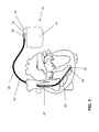
- FIG. 1 As an example of implantable medical devices, there is shown an implantable cardiac stimulator 10 and an implantable electrode lead 20 connected thereto.
- the implantable cardiac stimulator 10 may be a pacemaker or a cardioverter / defibrillator (ICD).
- the heart stimulator 10 is a ventricular pacemaker and defibrillator.
- Other known cardiac stimulators are dual chamber pacemakers for stimulation of the right atrium and right ventricle, or biventricular pacemakers, which can also stimulate the left ventricle in addition to the right ventricle.
- Such stimulators typically have a housing 12, which is usually made of metal and thus is electrically conductive and can serve as a large electrode pole.
- a terminal housing 14 is typically attached, which is also referred to as a header.
- Such a header typically has contact sockets for receiving plug contacts.
- the contact sockets have electrical contacts 16, which are connected via corresponding conductors with an arranged in the housing 12 of the heart stimulator 10 electronics.
- the electrode line 20 likewise constitutes an implantable medical device.
- electrode poles in the form of a tip or tip electrode 22 and a ring electrode 24 arranged in the vicinity thereof are arranged in a manner known per se.
- the electrode poles 22 and 24 are designed such that, depending on the function of a cardiac stimulator to which the electrode lead 20 is connected, they serve to sense electrical potentials of the heart tissue (myocardium) or to emit electrical signals, for example to deliver stimulation pulses to the surrounding them Heart tissue, are formed.
- Fig. 1 shows how the electrode poles, so the tip electrode 22 and the ring electrode 24, in the application, the electrode line 20, located in the apex of a right ventricle of a heart.
- Both the tip electrode 22 and the ring electrode 24 are electrically connected via at least one electrical conductor 26 with a plug contact 28 at the proximal end of the electrode line 20.
- the plug contact 28 has electrical contacts, the correspond with the electrical contacts 16 of the contact socket in the connection housing 14 of the implantable cardiac stimulator.
- the electrical conductors 26 may be formed in the electrode line 20 in different longitudinal sections as approximately elongated Seilzugleiter or as a helical coiled conductor.
- Such conductors which electrically conductively connect functional electrode poles to electrical contacts of the plug-in contact at the proximal end of the electrode lead 20 are also referred to as function leads in the context of this text, since they transmit electrical signals from plug contact to the respective electrode pole, for example, or sensed electrical potential signals lead from the respective electrode pole to the plug contact and thus serve the elementary function of the medical device.
- the electrical function conductors 26, which connect the electrode poles 22 and 24, respectively, to the electrical contacts of the plug 28 of the electrode line 20, are surrounded over most of their length by an insulating sheath, so that an electrical contact to the tissue of the heart is targeted via the electrode poles comes about.
- the electrode line 20 In addition to the electrode poles 22 and 24, which typically serve the (in this case, ventricular) stimulation of the heart tissue, the electrode line 20 also has two larger-area electrode poles 30 and 32, which serve as defibrillation electrodes and are formed by at least one bare helix-like coiled wire ,
- an ablation electrode lead can in principle also be used, which likewise projects into the heart of a patient in the application and which is controlled by a device arranged outside the patient and is connected to it for this purpose.
- electrode lines can also be used for stimulation and derivation of signals to nerves, brain, with customary adaptation to the special requirements of the respective field of application. and other organs, or for the delivery of implantable sensors.
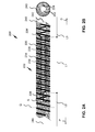
- Fig. 2 shows in her part figure Fig. 2a a schematic partial sectional view of an electrode line and in Fig. 2b a cross-sectional view of the electrode line Fig. 2a
- electrode line 220 is shown only in a portion of its longitudinal extent.
- This subsection corresponds in the present embodiment to an in Fig. 1
- piece of the electrode line 20 which contains the electrode pole 32, but may also represent the farther to the distal end lying portion with the electrode pole 30.
- Fig. 2A now shows a partially longitudinally cut side view of the electrode line 220.
- the electrode lead 220 is shown beyond a cut surface S in a distal direction D with a longitudinally-cut sheath 240.
- This alone serves to clarify the structure of the electrode line 220, which actually has a continuous closed casing 240, as it is visible on this side of the cut surface S in a proximal direction P.
- a function conductor 226 is guided from the proximal end of the electrode line 220, not shown here, to the beginning of a first longitudinal section L1, which contains the electrode pole 232, as a cable feed line in the casing 240.
- the leadership in the shell 240 is in the cross-sectional view of Fig. 2B recognizable, the cross-sectional plane Q in Fig. 2A is indicated by a dashed line.
- the electrode pole 232 In the first longitudinal section L1, the electrode pole 232, viewed as a whole, is annular, in that the functional conductor 226 is no longer guided here as a cable feed line, but helically.
- the function conductor 226 is uninsulated in this first longitudinal section L1 and wound around the cylinder jacket surface of the jacket 240. Subsequent to the first longitudinal section L1, the function conductor 226 is again guided in the casing 240, which is not shown here in detail. Also, the function conductor 226 ends at the point 226 'in the Fig. 2A , which is not mandatory.
- the function manager 226 can also be continued.
- the function conductor 226 is wound in the region of the electrode pole 232 to gap. In this longitudinal section and then both proximally and distally thereafter, an additional conductor 234 is wound helically around the sheath 240. In the region of the electrode pole 232, the function conductor 226 and the additional conductor 234 are corradial and wound on a gap. That is, the function conductor 226 and the additional conductor 234 wind in pairs adjacent to each other around the sheath 240 in a cylindrical surface formed by the outer surface of the sheath 240. Instead of one additional conductor 234, it is also possible to use a plurality of additional conductors.
- the additional conductor 234 and the function conductor 226 are electrically isolated from each other. This can be achieved for example even without isolation of the two conductors themselves by their distance in the longitudinal direction and by their winding on the insulating material of the sheath 240. Silicone, for example, but also any other suitable material for the application in question due to its mechanical, electrical and biological properties can be used for the casing 240.
- the function conductor 226 and the additional conductor 234 may be insulated from one another by a conductor insulation of the additional conductor 234.
- the additional conductor extends beyond the first longitudinal section L1 both in the proximal direction P in a second longitudinal section L2 and in the distal direction D in a third longitudinal section L3.
- the casing 240 has the shape of a flexible hollow cylinder, the cylinder axis 244 in Fig. 2A is drawn.
- FIGS. 2A and 2B shown structure succeeds in achieving an electromagnetic coupling between the function conductor 226 and the additional conductor 234.
- This coupling causes especially in the frequency range of electromagnetic radio-frequency waves, but in principle electromagnetic waves with frequencies that are significantly higher than the usual frequencies for therapeutic purposes and diagnostic frequencies, electromagnetic energy from the functional waveguide 226 in the additional conductor 234 einzkopppeln. Since, as explained in the introduction, high-frequency electromagnetic signals on the function conductor can be harmful, such damage can be avoided with the aid of the electrode line 220 and an undisturbed function of the electrode line can be ensured even in the presence of high-frequency electromagnetic alternating fields.
- the amplitude of the injected signal can be influenced by the longitudinal extent of the first length L1. The larger the coupling length, the greater the amplitude of the injected signal until reaching saturation.
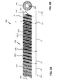
- Fig. 3 shows in her part figure Fig. 3A a schematic side view of an electrode line and Fig. 3b a cross-sectional view of the electrode line Fig. 3a ,
- the electrode line of FIGS. 3a and 3b is similar in many features of the electrode line 220 of FIGS. 2a and 2b , The following description therefore focuses solely on the differences between the two embodiments.
- the functional line 326 is also wound in a helical manner about the sheath 340 beyond the first longitudinal section L1, specifically the section with helical guidance extends in the proximal direction P over longitudinal sections L2 and L4.
- the function line in the longitudinal sections L1, L2 and L4 is continuously corradial and wound in a gap combined with the additional conductor 334.
- the additional conductor which could also be referred to as a loss spiral, is uninsulated in some longitudinal sections.
- the additional conductor 334 is uninsulated in the longitudinal section L4, while it is subsequently made insulated in the longitudinal section L2 and in the adjoining longitudinal sections L1 and L3.
- the conductor insulation provided in the latter three longitudinal sections may be omitted if the additional conductor is sufficiently insulated from the functional conductor 326 by the insulating material of the sheath 340.
- the function conductor 326 is, as in the previous embodiment, uninsulated in the first longitudinal section L1 to enable its therapeutic or diagnostic function.
- the electrode line 332 of the present embodiment allows increased inductive and capacitive coupling between the function conductor 326 and the auxiliary conductor 334 because of its divergent features. In addition, it allows for the delivery of electromagnetic energy outside the first longitudinal region L1 of the functional electrode pole 332, namely in the longitudinal regions L4, in which the additional conductor 334 is not isolated against the body tissue.
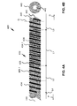
- Fig. 4 shows in her part figure Fig. 4a a schematic side view of an electrode line and in Fig. 4B a cross-sectional view of the electrode line Fig. 4A
- the electrode line 420 of the present embodiment is similar to that of FIG Fig. 3 and differs only in that the additional conductor 434 in all longitudinal sections, in which it is performed with the functional guide 426 koradial isolated.
- the additional conductor 434 extends helically around the outer surface of the sheath 440 along the electrode line 420 in the proximal direction only until shortly after the beginning of the fourth longitudinal section L4. He still has it however, extends beyond the illustrated longitudinal sections within the sheath 440. This design reduces the coupling between the functional conductor 426 and the additional conductor 434 and limits it to the electrode pole 432 and its immediate surroundings.
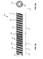
- Fig. 5 shows in her part figure Fig. 5A a schematic side view of an electrode line and in Fig. 5B a cross-sectional view of the electrode line Fig. 5A
- the electrode line 520 of the present embodiment has a functional line 526 insulated in longitudinal portions outside the electrode pole 532.
- the additional conductor 534 is continuously insulated.
- the functional conductor 526 and the additional conductor 534 have different thicknesses in the present embodiment, ie conductor or wire thicknesses.
- the insulation of one of the two conductors 526 and 534 may have a different thickness, ie thickness, than the insulation of the other conductor.
- the functional conductor 526 has a thicker insulation than the additional conductor 534 and in addition a higher conductor thickness, ie wire thickness, without taking into account the surrounding insulation.
- the outer diameter of the stripped functional conductor in the first longitudinal region L1 of the functional electrode 532 intentionally resembles the outer diameter of the additional conductor 534 insulated in this region.
- This embodiment has the advantage that theannoselektrodenpol 532 can be easily prepared by stripping the function conductor, without damaging the insulation of the additional conductor 534.
- the additional conductor 534 is uninsulated and the functional conductor 526 isolated. In this way, portions of the additional lead 534 may be directly contacted with the tissue to facilitate heat dissipation over a passive electrode area not used for therapeutic or diagnostic purposes.
- the exemplary embodiment makes it possible to facilitate selective stripping for producing either a functional electrode pole or the passive electrode region.
- the embodiments of the FIGS. 2 to 5 have gap-wound function and additional conductors.
- the advantage of this winding on gap is its particularly high compressibility.
- Fig. 6 shows in her part figure Fig. 6A a schematic sectional view of an electrode line and in Fig. 6B a cross-sectional view of the electrode line Fig. 6A , Unlike in the embodiments previously shown and discussed above, the electrode line 620 has an interruption of the cladding 640 in the region of the electrode pole 632.
- the function conductor 626 and the additional conductor 635 are wound on a block in a corotid and helical manner.
- the functional conductor 626 and the additional conductor 634 are insulated from each other.
- the additional conductor 634 extends beyond the longitudinal section L1 of the electrode pole 632 designed as a ring electrode, also proximally in the longitudinal section L2 and distally also in the longitudinal section L3.
- the functional conductor 626 is continuously helically guided and extends in the longitudinal section L4, that is from a proximal electrode connection up to the region of the electrode pole 632, in the lumen 642 of the sheath 640.
- This exemplary embodiment has a particularly strong longitudinal section L1 of the electrode pole 632 inductive and capacitive coupling between the functional conductor 626 and the additional conductor 634.
- FIG. 7 shows in her part figure Fig. 7A a schematic partial side view of an electrode line and in Fig. 7B a cross-sectional view of the electrode line Fig. 7A , wherein in each case a sheath is present, which is not shown here.
- the embodiment of FIGS. 7A and 7B is different from that of Fig. 6 solely in that the functional conductor 726 is led to the longitudinal section L1 of the electrode pole 732 as a cable feed line.
- the function guide is guided in these longitudinal sections L2 and L4, in which it is designed as a cable feed line, in the lumen of the electrode line 720, not on a central axis of the hollow cylinder formed by the electrode pole 732.
Abstract
Description
Die Erfindung betrifft ein permanent oder temporär implantierbares medizinisches Gerät mit einem langgestreckten elektrischen Leiter.The invention relates to a permanently or temporarily implantable medical device with an elongated electrical conductor.
Solche Geräte, beispielsweise Elektrodenleitungen für die Elektrostimulation, haben den Nachteil, dass sich ihr elektrischer Leiter in einem Kernspintomografen erwärmen kann, weil die im Kernspintomografen herrschenden wechselnden Magnetfelder in dem elektrischen Leiter nicht unbeachtliche elektrische Ströme induzieren. Deshalb können Herzschrittmacherpatienten heutzutage in der Regel nicht oder nur eingeschränkt in einem Kernspintomografen untersucht werden.Such devices, for example, electrode lines for electrical stimulation, have the disadvantage that their electrical conductor can heat up in a magnetic resonance tomograph, because the prevailing magnetic resonance in the magnetic resonance field inducing magnetic currents in the electrical conductor not inconsiderable. Therefore, cardiac pacemaker patients today can usually not be examined or only to a limited extent in a magnetic resonance tomograph.
An implantierbaren Herzschrittmachern oder Defibrillatoren sind nämlich typischerweise wenigstens eine Stimulationselektrodenleitung angeschlossen, die an ihrem proximalen, zum Anschluss an den Herzschrittmacher oder Defibrillator vorgesehenen Ende einen standardisierten elektrischen Anschluss aufweist und an ihrem distalen, zur Platzierung im Herzen vorgesehenen Ende einen oder mehrere Elektrodenpole aufweist. Ein solcher Elektrodenpol dient zur Abgabe elektrischer Impulse, beispielsweise an das Gewebe (Myokard) des Herzens oder zum Abfühlen elektrischer Felder, um im Rahmen des sogenannten Sensings eine Aktivität, beispielsweise eine Herzaktivität abfühlen zu können.Namely, implantable cardiac pacemakers or defibrillators typically have at least one pacing lead connected to their proximal end for connection to the pacemaker or defibrillator with a standard electrical connection and one or more electrode poles at their distal end provided for placement in the heart. Such an electrode pole serves to deliver electrical impulses, for example to the tissue (myocardium) of the heart or to sense electric fields, in order to be able to sense an activity, for example a cardiac activity, within the scope of so-called sensing.
Zu diesen Zwecken bilden Elektrodenpole typischerweise elektrisch leitende Oberflächenabschnitte einer Elektrodenleitung. Elektrodenpole sind typischerweise als Ringelektrode in Form eines Rings um die Elektrodenleitung oder in Form einer Spitzen- oder Tippelektrode am distalen Ende der Elektrodenleitung vorgesehen.For these purposes, electrode poles typically form electrically conductive surface portions of an electrode lead. Electrode poles are typically provided as a ring electrode in the form of a ring around the electrode lead or in the form of a tip or tip electrode at the distal end of the electrode lead.
Die Elektrodenpole sind über einen oder mehrere elektrische Leiter mit Kontakten des elektrischen Anschlusses der Elektrodenleitung an deren proximalem Ende elektrisch leitend verbunden. Somit verlaufen zwischen den Kontakten des elektrischen Anschlusses die Elektrodenleitungen an deren proximalem Ende und den Elektrodenpolen am distalen Ende der Elektrodenleitung ein oder mehrere elektrische Leiter, die einen oder mehrere der Elektrodenpole mit einem oder mehreren der Kontakte elektrisch verbinden. Diese elektrischen Leiter können einerseits zur Übertragung von Stimulationsimpulsen zu den Elektrodenpolen und andererseits zur Übertragung mittels der Elektrodenpole aufgenommener elektrischer Signale zum proximalen Ende der Elektrodenleitung genutzt werden und werden im Verlauf der weiteren Beschreibung auch jeweils als Funktionsleiter bezeichnet.The electrode poles are electrically conductively connected via one or more electrical conductors to contacts of the electrical connection of the electrode line at its proximal end. Thus, between the contacts of the electrical connection, the electrode leads extend at the proximal end thereof and the electrode poles at the distal end of the electrode lead one or more electrical conductors electrically connecting one or more of the electrode poles to one or more of the contacts. These electrical conductors can be used, on the one hand, to transmit stimulation pulses to the electrode poles and, on the other hand, to transmit electrical signals picked up by the electrode poles to the proximal end of the electrode line and will also be referred to as function conductors in the course of the further description.
Solche Funktionsleiter sind für die Funktionen der jeweiligen Elektrodenleitung erforderliche elektrische Leiter und als solche der Gefahr ausgesetzt, dass in ihnen durch äußere Wechselmagnetfelder elektrische Ströme induziert werden, die beispielsweise zu einer unerwünschten Erwärmung der Funktionsleitungen oder der mit ihr verbundenen Elektrodenpole führen können oder die zur Abgabe entsprechender Ströme über die Elektrodenpole an umgebendes Gewebe und damit zu einer Erwärmung des umgebenden Gewebes führen können.Such functional conductors are required for the functions of the respective electrode line required electrical conductors and as such the risk that in them by external alternating magnetic fields electrical currents are induced, which can lead, for example, to an undesirable heating of the function lines or the associated electrode poles or the delivery corresponding currents can lead to the surrounding tissue via the electrode poles and thus to a heating of the surrounding tissue.
Der Erfindung liegt die Aufgabe zugrunde, ein medizinisches Gerät zu schaffen, welches das zuvor beschriebene Problem löst.The invention has for its object to provide a medical device which solves the problem described above.
Erfindungsgemäß wird diese Aufgabe gelöst durch ein temporär oder permanent implantierbares medizinisches Gerät, mit mindestens einer langgestreckten elektrischen Leitung, die einen Funktionsleiter enthält, welcher mit einem Elektrodenpol zur Abgabe von Therapiesignalen oder zur Erfassung von Diagnosesignalen verbunden ist, wobei der Funktionsleiter oder der Elektrodenpol oder sowohl der Funktionsleiter als auch der Elektrodenpol in einem ersten Längsabschnitt ringförmig ausgebildet ist; und die mindestens einen zweiten elektrischen Leiter enthält, der in dem ersten Längsabschnitt wendelförmig geführt ist, derart, dass im ersten Leiter führbare elektromagnetische Radiofrequenz-Wellen zumindest teilweise im ersten Längsabschnitt in den zweiten elektrischen Leiter einkoppelbar sind. Das erfindungsgemäße medizinische Gerät erzielt eine Verringerung der unerwünschten Erwärmung des Funktionsleiters oder eines mit ihm verbundenen Elektrodenpols, die durch elektrische Ströme verursacht werden, welche äußere Wechselmagnetfelder im Funktionsleiter der elektrischen Leitung induzieren können. Auf diese Weise kann eine unerwünschte Erwärmung von Körpergewebe im implantierten Zustand reduziert, zumindest teilweise auf andere Gewebebereiche verlagert oder sogar vollständig vermieden werden. Dies gelingt erfindungsgemäß mit Hilfe eines in dem ersten Längsabschnitt wendelförmigen zweiten elektrischen Leiters und mit Hilfe einer Kopplung zwischen dem ersten und dem zweiten elektrischen Leiter, die ausgebildet ist, im ersten Leiter geführte elektromagnetische Radiofrequenz-Wellen zumindest teilweise in den zweiten elektrischen Leiter einzukoppeln.According to the invention, this object is achieved by a medical device which can be implanted temporarily or permanently, with at least one elongate electrical line which contains a function conductor which is connected to an electrode pole for delivery of therapy signals or for detection of diagnostic signals, wherein the function conductor or the electrode pole or both the functional conductor as well as the electrode pole is annular in a first longitudinal section; and the at least one second electrical conductor, which is guided in a helical manner in the first longitudinal section, such that in the first conductor feasible electromagnetic radio-frequency waves can be coupled at least partially in the first longitudinal section in the second electrical conductor. The medical device according to the invention achieves a reduction in the unwanted heating of the functional conductor or of an electrode pole connected to it, which are caused by electrical currents which can induce external alternating magnetic fields in the functional conductor of the electrical conductor. In this way, unwanted heating of body tissue in the implanted state can be reduced, at least partially shifted to other tissue areas or even completely avoided. This is achieved according to the invention by means of a helical in the first longitudinal section second electrical conductor and by means of a coupling between the first and the second electrical conductor, which is designed to couple in the first conductor guided electromagnetic radio frequency waves at least partially in the second electrical conductor.
Zusätzlich werden durch diesen zusätzlich geführten Leiter die mechanischen Eigenschaften optimiert. Das betrifft beispielsweise eine optimierte Biegefestigkeit und Festigkeit gegenüber äußeren mechanischen Einflüssen wie Quetschung, Knickung, Dehnung, Torsion. Damit sinkt auch die Gefahr eines so genannten "Subclavian Crush".In addition, the mechanical properties are optimized by this additional guided conductor. This concerns, for example, an optimized flexural strength and resistance to external mechanical influences such as pinching, buckling, stretching, torsion. This also reduces the danger of a so-called "subclavian crush".
Nachfolgend werden Ausführungsbeispiele des medizinischen Geräts der vorliegenden Erfindung erläutert. Die zusätzlichen Merkmale der einzelnen Ausführungsbeispiele können miteinander zur Bildung weiterer Ausführungsformen des medizinischen Geräts kombiniert werden, soweit sie nicht ausdrücklich als einander ausschließende Alternativen beschrieben sind.Hereinafter, embodiments of the medical device of the present invention will be explained. The additional features of the individual embodiments can be combined with each other to form further embodiments of the medical device, unless they are expressly described as mutually exclusive alternatives.
Der Funktionsleiter oder der Elektrodenpol, oder sowohl der Funktionsleiter als auch der Elektrodenpol sind in einem ersten Längsabschnitt ringförmig ausgebildet. Sowohl der Funktionsleiter als auch der Elektrodenform können die Ringform durch eine wendelförmige Wicklung eines Leiters annehmen. Insbesondere ist in einer Ausführungsform der ringförmig ausgebildete Elektrodenpol von dem im ersten Längsabschnitt unisoliert und wendelförmig geführten Funktionsleiter gebildet ist.The functional conductor or the electrode pole, or both the functional conductor and the electrode pole are annular in a first longitudinal section. Both the functional conductor and the electrode mold can adopt the ring shape by a helical winding of a conductor. In particular, in one embodiment, the ring-shaped electrode pole is formed by the function conductor which is uninsulated and helically guided in the first longitudinal section.
Der zweite elektrische Leiter enthält in bevorzugten Ausführungsbeispielen keinen Funktionsleiter, sondern einen oder mehrere Zusatzleiter.The second electrical conductor contains in preferred embodiments no functional conductor, but one or more additional conductors.
Bevorzugt sind der Funktionsleiter und der zweite elektrische Leiter auf einer gemeinsamen, gedachten Zylindermantel-Fläche wendelförmig geführt. Der Funktionsleiter und der zweite elektrische Leiter können im ersten Längsabschnitt als von einander elektrisch isoliertes Leiterpaar koradial geführt sein.The functional conductor and the second electrical conductor are preferably helically guided on a common, imaginary cylinder jacket surface. The function conductor and the second electrical conductor can be guided in the first longitudinal section as a pair of electrically insulated conductor pair koradial.
In alternativen Ausführungsformen sind der Funktionsleiter und der zweite elektrische Leiter im ersten Längsabschnitt auf Block gewickelt oder auf Lücke gewickelt sind. Die Wicklung auf Lücke zeichnet sich durch eine höhere Kompressibilität in Längsrichtung der elektrischen Leitung aus.In alternative embodiments, the function conductor and the second electrical conductor in the first longitudinal section are wound on block or wound on a gap. The winding on gap is characterized by a higher compressibility in the longitudinal direction of the electrical line.
Der Funktionsleiter kann außerhalb des ersten Längsabschnitts entweder wendelförmig oder als Seilzuleitung ausgebildet sein.The functional guide can be formed outside the first longitudinal section either helically or as a cable feed line.
Bei einer wendelförmigen Führung des Funktionsleiters hat die elektrische Leitung eine isolierende hohlzylindrische Ummantelung, die im Inneren ein Lumen aufweist, in dem eine Innenwendel des ersten elektrischen Leiters geführt ist. Alternativ kann die Seilzuleitung außerhalb des ersten Längsabschnitts in die Ummantelung eingebettet sein.In a helical guide of the functional conductor, the electrical line has an insulating hollow-cylindrical casing, which has a lumen inside, in which an inner spiral of the first electrical conductor is guided. Alternatively, the cable feed line can be embedded outside the first longitudinal section in the casing.
Der zweite elektrische Leiter ist in einer Ausführungsform im ersten Längsabschnitt von einer Leiterisolierung umgeben, um etwa im Bereich eines Elektrodenpols eine Abgabe von eingekoppelter Energie aus dem zweiten elektrischen Leiter in das umgebende Körpergewebe so gering wie möglich zu halten. In anderen Längsabschnitten kann der zweite elektrische Leiter Ansonsten teilweise oder vollständige unisoliert ausgeführt werden.In one embodiment, the second electrical conductor is surrounded by a conductor insulation in the first longitudinal section in order to minimize the emission of coupled energy from the second electrical conductor into the surrounding body tissue, for example in the region of an electrode pole. Otherwise, the second electrical conductor may be partially or completely uninsulated in other longitudinal sections.
Um die Herstellung dieses Ausführungsbeispiels zu vereinfachen, hat der zweite elektrische Leiter vorteilhafterweise einen anderen Durchmesser hat als der Funktionsleiter. Dies kann durch unterschiedliche Drahtstärken oder Isolationsdurchmesser realisiert werden und vereinfacht ein Abisolieren des zweiten elektrischen Leiters in passiven Bereichen des Elektrodenpols.In order to simplify the manufacture of this embodiment, the second electrical conductor advantageously has a different diameter than the function conductor. This can be realized by different wire thicknesses or insulation diameters and simplifies stripping of the second electrical conductor in passive regions of the electrode pole.
Der zweite elektrische Leiter kann in Längsabschnitten außerhalb des ersten Längsabschnitts auf eine Ummantelung der des ersten elektrischen Leiters gewickelt sein. Dabei ist der zweite elektrische Leiter vorzugsweise in einem aktiven Teil, also an einem anderen als einem Funktionselektrodenpol teils unisoloiert, im inaktiven Teil jedoch isoliert.The second electrical conductor may be wound in longitudinal sections outside the first longitudinal section on a jacket of the first electrical conductor. In this case, the second electrical conductor is preferably partially isolated in an active part, that is to say at a point other than a functional electrode pole, but isolated in the inactive part.
Der Funktionsleiter und der zweite elektrische Leiter sind in einem anderen Ausführungsbeispiel im ersten Längsabschnitt in eine elektrisch isolierende Ummantelung des ersten elektrischen Leiters eingebettet.In another embodiment, the functional conductor and the second electrical conductor are embedded in the first longitudinal section in an electrically insulating sheathing of the first electrical conductor.
Zur Erhöhung der Kopplung zwischen dem Funktionsleiter bzw. dem Elektrodenpol im ersten Längsabschnitt und dem zweiten elektrischen Leiter erstreckt sich der zweite elektrische Leiter in einer Ausführungsform in proximaler oder distaler Richtung oder sowohl in proximaler als auch in distaler Richtung wendelförmig gewickelt über den ersten Längsabschnitt hinaus.To increase the coupling between the function conductor or the electrode pole in the first longitudinal section and the second electrical conductor, the second electrical conductor extends in an embodiment in the proximal or distal direction or helically wound in both the proximal and in the distal direction beyond the first longitudinal section.
Die langgestreckte elektrische Leitung ist in bevorzugten Ausführungsbeispielen eine temporär oder permanent implantierbare Elektrodenleitung zur Verbindung eines oder mehrerer Funktions-Elektrodenpole mit einem Steuergerät, wie beispielsweise dem Steuergerät eines implantierbaren Herzschrittmachers oder eines implantierbaren Defibrillators. Die langgestreckte Leitung bildet jedoch als solche schon ein medizinisches Gerät im Sinne der vorliegenden Beschreibung.The elongate electrical lead, in preferred embodiments, is a temporarily or permanently implantable electrode lead for connecting one or more functional electrode poles to a controller, such as the controller of an implantable cardiac pacemaker or implantable defibrillator. However, the elongated line as such already constitutes a medical device in the sense of the present description.
Nachfolgend werden weitere Ausführungsbeispiele anhand der Figuren erläutert. Es zeigen:
- Fig. 1
- ein Ausführungsbeispiel eines erfindungsgemäßen medizinischen Geräts in Form eines Herzschrittmachers;
- Fig. 2
- in ihrer Teilfigur
Fig. 2A eine schematische teilweise Schnittansicht einer Elektrodenleitung undFig. 2B eine Querschnittsansicht der Elektrodenleitung ausFig. 2A ; - Fig. 3
- in ihrer Teilfigur
Fig. 3A eine schematische Seitenansicht einer Elektrodenleitung undFig. 3B eine Querschnittsansicht der Elektrodenleitung ausFig. 3A ; - Fig. 4
- in ihrer Teilfigur
Fig. 4A eine schematische Seitenansicht einer Elektrodenleitung undFig. 4B eine Querschnittsansicht der Elektrodenleitung ausFig. 4A ; - Fig. 5
- in ihrer Teilfigur
Fig. 5A eine schematische Seitenansicht einer Elektrodenleitung undFig. 5B eine Querschnittsansicht der Elektrodenleitung ausFig. 5A ; - Fig. 6
- in ihrer Teilfigur
Fig. 6A eine schematische Schnittansicht einer Elektrodenleitung undFig. 6B eine Querschnittsansicht der Elektrodenleitung ausFig. 6A ; - Fig. 7
- in ihrer Teilfigur
Fig. 7A eine schematische teilweise Seitenansicht einer Elektrodenleitung undFig. 7B eine Querschnittsansicht der Elektrodenleitung ausFig. 7A ;
- Fig. 1
- An embodiment of a medical device according to the invention in the form of a pacemaker;
- Fig. 2
- in her part character
Fig. 2A a schematic partial sectional view of an electrode line andFig. 2B a cross-sectional view of the electrode lineFig. 2A ; - Fig. 3
- in her part character
Fig. 3A a schematic side view of an electrode line andFig. 3B a cross-sectional view of the electrode lineFig. 3A ; - Fig. 4
- in her part character
Fig. 4A a schematic side view of an electrode line andFig. 4B a cross-sectional view of the electrode lineFig. 4A ; - Fig. 5
- in her part character
Fig. 5A a schematic side view of an electrode line andFig. 5B a cross-sectional view of the electrode lineFig. 5A ; - Fig. 6
- in her part character
Fig. 6A a schematic sectional view of an electrode line andFig. 6B a cross-sectional view of the electrode lineFig. 6A ; - Fig. 7
- in her part character
Fig. 7A a schematic partial side view of an electrode line andFig. 7B a cross-sectional view of the electrode lineFig. 7A ;
Der implantierbare Herzstimulator 10 kann ein Herzschrittmacher oder ein Kardioverter/Defibrillator (ICD) sein. Im dargestellten Ausführungsbeispiel ist der Herzstimulator 10 ein ventrikulärer Herzschrittmacher und Defibrillator. Andere bekannte Herzstimulatoren sind Zweikammerherzschrittmacher zur Stimulation des rechten Atriums und des rechten Ventrikels oder biventrikuläre Herzschrittmacher, die zusätzlich zum rechten Ventrikel auch den linken Ventrikel stimulieren können.The implantable
Derartige Stimulatoren besitzen typischerweise ein Gehäuse 12, das im Regelfall aus Metall besteht und somit elektrisch leitend ist und als großflächiger Elektrodenpol dienen kann. An der Außenseite des Gehäuses 12 ist typischerweise ein Anschlussgehäuse 14 befestigt, das auch als Header bezeichnet wird. Ein derartiger Header weist typischerweise Kontaktbuchsen zur Aufnahme von Steckkontakten auf. Die Kontaktbuchsen besitzen elektrische Kontakte 16, die über entsprechende Leiter mit einer in dem Gehäuse 12 des Herzstimulators 10 angeordneten Elektronik verbunden sind.Such stimulators typically have a
Die Elektrodenleitung 20 stellt im Sinne dieser Erfindung ebenfalls ein implantierbares medizinisches Gerät dar. Am distalen Ende der Elektrodenleitung 20 sind in an sich bekannter Manier Elektrodenpole in Form einer Spitzen- oder Tip-Elektrode 22 und einer in deren Nähe angeordneten Ringelektrode 24 angeordnet. Die Elektrodenpole 22 und 24 sind so ausgebildet, dass sie je nach Funktion eines Herzstimulators, an den die Elektrodenleitung 20 angeschlossen ist, zum Abfühlen elektrischer Potenziale des Herzgewebes (Myokards) dienen oder zur Abgabe elektrischer Signale, beispielsweise zur Abgabe von Stimulationsimpulsen an das sie umgebende Herzgewebe, ausgebildet sind.
Sowohl die Tip-Elektrode 22 als auch die Ringelektrode 24 sind über jeweils wenigstens einen elektrischen Leiter 26 mit einem Steckkontakt 28 am proximalen Ende der Elektrodenleitung 20 elektrisch verbunden. Der Steckkontakt 28 besitzt elektrische Kontakte, die mit den elektrischen Kontakten 16 der Kontaktbuchse im Anschlussgehäuse 14 des implantierbaren Herzstimulators korrespondieren.Both the
Wie weiter unten näher erläutert wird, können die elektrischen Leiter 26 in der Elektrodenleitung 20 in unterschiedlichen Längsabschnitten als annähernd gestreckte Seilzugleiter oder als helixförmig gewendelte Leiter ausgebildet sein. Solche Leiter, die funktionale Elektrodenpole mit elektrischen Kontakten des Steckkontaktes am proximalen Ende der Elektrodenleitung 20 elektrisch leitend verbinden werden im Rahmen dieses Textes auch als Funktionsleiter bezeichnet, da sie beispielsweise der Therapie dienende elektrische Signale von Steckkontakt zum jeweiligen Elektrodenpol übertragen oder abgefühlte elektrische Potentiale repräsentierende Signale vom jeweiligen Elektrodenpol zum Steckkontakt führen und somit der elementaren Funktion des medizinischen Gerätes dienen.As will be explained in more detail below, the
Die elektrischen Funktionsleiter 26, die die Elektrodenpole 22 bzw. 24 mit den elektrischen Kontakten des Steckers 28 der Elektrodenleitung 20 verbinden, sind über den größten Teil ihrer Länge von einer isolierenden Hülle umgeben, so dass ein elektrischer Kontakt zum Gewebe des Herzens gezielt über die Elektrodenpole zustande kommt.The
Neben den Elektrodenpolen 22 und 24, die typischerweise der (in diesem Fall ventrikulären) Stimulation des Herzgewebes dienen, weist die Elektrodenleitung 20 auch noch zwei großflächigere Elektrodenpole 30 und 32 auf, die als Defibrillationselektroden dienen und von wenigstens einem blank liegendem helixartig gewendelten Draht gebildet sind.In addition to the
Es sei darauf hingewiesen, dass die Erfindung im Rahmen dieses Ausführungsbeispiels anhand eines rechtsventrikulären Herzschrittmachers und Defibrillators erläutert wird. Als medizinisches Gerät im Sinne der Erfindung kann grundsätzlich aber beispielsweise auch eine Ablationselektrodenleitung dienen, die im Anwendungsfall ebenfalls bis ins Herz eines Patienten hineinragt und die von einem außerhalb des Patienten angeordneten Gerät gesteuert wird und hierzu mit diesem verbunden ist. Weiterhin können solche Elektrodenleitungen unter fachüblicher Anpassung an die speziellen Erfordernisse des jeweiligen Anwendungsgebiets auch zur Stimulation und Ableitung von Signalen an Nerven, Gehirn, und anderen Organen oder für die Zuleitung von implantierbaren Sensoren Verwendung finden.It should be noted that the invention is explained in the context of this embodiment with reference to a right ventricular pacemaker and defibrillator. As a medical device within the meaning of the invention, however, an ablation electrode lead can in principle also be used, which likewise projects into the heart of a patient in the application and which is controlled by a device arranged outside the patient and is connected to it for this purpose. Furthermore, such electrode lines can also be used for stimulation and derivation of signals to nerves, brain, with customary adaptation to the special requirements of the respective field of application. and other organs, or for the delivery of implantable sensors.
Zur Verdeutlichung dieses Zusammenhangs werden für die Elektrodenleitung und den genannten Elektrodenpol in der vorliegenden Darstellung ähnliche Bezugszeichen wie in
Ein Funktionsleiter 226 ist vom hier nicht dargestellten proximalen Ende der Elektrodenleitung 220 bis zum Beginn eines ersten Längsabschnitts L1, der den Elektrodenpol 232 enthält, als Seilzuleitung in der Ummantelung 240 geführt. Die Führung in der Ummantelung 240 ist in der Querschnittdarstellung der
Im ersten Längsabschnitt L1 ist der Elektrodenpol 232 als Ganzes betrachtet ringförmig ausgebildet, indem der Funktionsleiter 226 hier nicht mehr als Seilzuleitung, sondern wendelförmig geführt ist. Der Funktionsleiter 226 ist in diesem ersten Längsabschnitt L1 unisoliert und um die Zylinder-Mantelfläche der Ummantelung 240 gewickelt. Im Anschluss an den ersten Längsabschnitt L1 wird der Funktionsleiter 226 wiederum in der Ummantelung 240 geführt, was hier im Einzelnen nicht dargestellt ist. Auch endet der Funktionsleiter 226 an der Stelle 226' in der
Der Funktionsleiter 226 ist im Bereich des Elektrodenpols 232 auf Lücke gewickelt. In diesem Längsabschnitt und sowohl proximal als auch distal daran anschließend ist ein Zusatzleiter 234 wendelförmig um die Ummantelung 240 gewickelt. Im Bereich des Elektrodenpols 232 sind der Funktionsleiter 226 und der Zusatzleiter 234 koradial und auf Lücke gewickelt. Das heißt, der Funktionsleiter 226 und der Zusatzleiter 234 winden sich paarweise nebeneinander um die Ummantelung 240 in einer von der Außenfläche der Ummantelung 240 gebildeten Zylinder-Mantelfläche. Anstelle des einen Zusatzleiters 234 können auch mehrere Zusatzleiter Verwendung finden.The
Der Zusatzleiter 234 und der Funktionsleiter 226 sind gegeneinander elektrisch isoliert. Dies kann beispielsweise schon ohne Isolierung der beiden Leiter selbst durch ihren Abstand in Längsrichtung und durch ihre Wickelung auf das isolierende Material der Ummantelung 240 erreicht werden. Für die Ummantelung 240 kann beispielsweise Silikon, aber auch jedes andere für den betreffenden Anwendungszweck aufgrund seiner mechanischen, elektrischen und biologischen Eigenschaften geeignete Material verwendet werden. Alternativ können der Funktionsleiter 226 und der Zusatzleiter 234 zueinander durch eine Leiterisolierung des Zusatzleiters 234 isoliert sein.The
Der Zusatzleiter erstreckt sich über den ersten Längsabschnitt L1 hinaus sowohl in der proximalen Richtung P in einem zweiten Längsabschnitt L2 als auch in der distalen Richtung D in einem dritten Längsabschnitt L3.The additional conductor extends beyond the first longitudinal section L1 both in the proximal direction P in a second longitudinal section L2 and in the distal direction D in a third longitudinal section L3.
Die vorliegende Darstellung verzichtet der Einfachheit halber auf hier nicht näher relevante Details, wie beispielsweise zusätzliche mögliche Funktionsleiter, die in einem Lumen 242 der Elektrodenleitung 220 geführt sein können. Die Ummantelung 240 hat die Form eines flexiblen Hohlzylinders, dessen Zylinderachse 244 in
Mit der in
Die Amplitude des eingekoppelten Signals kann durch die Längserstreckung des ersten Längenabschnitts L1 beeinflusst werden. Je größer die Koppellänge, desto größer ist die Amplitude des eingekoppelten Signals bis zum Erreichen einer Sättigung.The amplitude of the injected signal can be influenced by the longitudinal extent of the first length L1. The larger the coupling length, the greater the amplitude of the injected signal until reaching saturation.
Anders als im Beispiel der
Im vorliegenden Ausführungsbeispiel ist der Zusatzleiter, der auch als Verlustwendel bezeichnet werden könnte, in einigen Längsabschnitten unisoliert. Beispielsweise ist der Zusatzleiter 334 im Längsabschnitt L4 unisoliert, während er daran anschließend im Längsabschnitt L2 sowie in den daran anschließenden Längsabschnitten L1 und L3 isoliert ausgeführt ist. Die in den letztgenannten drei Längsabschnitten vorgesehene Leiterisolierung kann alternativ auch fortgelassen werden, wenn der Zusatzleiter ausreichend vom Funktionsleiter 326 durch das isolierende Material der Ummantelung 340 isoliert ist.In the present embodiment, the additional conductor, which could also be referred to as a loss spiral, is uninsulated in some longitudinal sections. By way of example, the
Der Funktionsleiter 326 ist, wie im vorhergehenden Ausführungsbeispiel, im ersten Längsabschnitt L1 unisoliert, um seine therapeutische oder diagnostische Funktion zu ermöglichen. Die Elektrodenleitung 332 des vorliegende n Ausführungsbeispiels ermöglicht aufgrund ihrer abweichenden Merkmale eine erhöhte induktive und kapazitive Kopplung zwischen dem Funktionsleiter 326 und dem Zusatzleiter 334. Darüber hinaus ermöglicht sie eine Abgabe von elektromagnetischer Energie außerhalb des ersten Längsbereiches L1 des funktionellen Elektrodenpols 332, nämlich in den Längsbereichen L4, in denen der Zusatzleiter 334 nicht gegen das Körpergewebe isoliert ist.The
Diese Ausführungsform hat den Vorteil, dass der Funktionselektrodenpol 532 durch Abisolieren des Funktionsleiters leicht hergestellt werden kann, ohne die Isolierung des Zusatzleiters 534 zu beschädigen.This embodiment has the advantage that the
In anderen - hier nicht dargestellten - Längsabschnitten ist allein der Zusatzleiter 534 unisoliert ist und der Funktionsleiter 526 isoliert. Auf diese Weise können Bereiche des Zusatzleiters 534 direkt mit dem Gewebe kontaktiert werden, um eine Wärmeableitung über einen passiven, nicht für therapeutische oder diagnostische Zwecke genutzten Elektrodenbereichs zu ermöglichen. Das Ausführungsbeispiel ermöglicht im Rahmen der Herstellung der Elektrodenleitung eine erleichterte selektive Abisolierung zur Herstellung entweder eines Funktionselektrodenpols oder des passiven Elektrodenbereichs.In other - not shown here - longitudinal sections alone the
Die Ausführungsbeispiele der
Claims (15)
Applications Claiming Priority (1)
| Application Number | Priority Date | Filing Date | Title |
|---|---|---|---|
| US201061424690P | 2010-12-20 | 2010-12-20 |
Publications (2)
| Publication Number | Publication Date |
|---|---|
| EP2478933A2 true EP2478933A2 (en) | 2012-07-25 |
| EP2478933A3 EP2478933A3 (en) | 2013-05-08 |
Family
ID=46235391
Family Applications (1)
| Application Number | Title | Priority Date | Filing Date |
|---|---|---|---|
| EP11192603.6A Withdrawn EP2478933A3 (en) | 2010-12-20 | 2011-12-08 | Implantable device |
Country Status (2)
| Country | Link |
|---|---|
| US (1) | US20120158109A1 (en) |
| EP (1) | EP2478933A3 (en) |
Families Citing this family (3)
| Publication number | Priority date | Publication date | Assignee | Title |
|---|---|---|---|---|
| DE202013103247U1 (en) * | 2013-07-19 | 2013-07-30 | Hannys Angel Limited | therapy device |
| EP2985053A1 (en) * | 2014-08-13 | 2016-02-17 | BIOTRONIK SE & Co. KG | Implantable electrical line |
| DE102015121817A1 (en) | 2015-12-15 | 2017-06-22 | Biotronik Se & Co. Kg | Stretchable electrode |
Family Cites Families (6)
| Publication number | Priority date | Publication date | Assignee | Title |
|---|---|---|---|---|
| JP2002501402A (en) * | 1996-12-19 | 2002-01-15 | メドトロニック・インコーポレーテッド | Medical electrical lead |
| US6249708B1 (en) * | 1997-08-26 | 2001-06-19 | Angeion Corporation | Fluted channel construction for a multi-conductor catheter lead |
| US7239923B1 (en) * | 2000-08-01 | 2007-07-03 | Cardiac Pacemakers, Inc. | Lead having varying stiffness and method of manufacturing thereof |
| US7107105B2 (en) * | 2002-09-24 | 2006-09-12 | Medtronic, Inc. | Deployable medical lead fixation system and method |
| US8103360B2 (en) * | 2008-05-09 | 2012-01-24 | Foster Arthur J | Medical lead coil conductor with spacer element |
| US8364281B2 (en) * | 2008-11-07 | 2013-01-29 | W. L. Gore & Associates, Inc. | Implantable lead |
-
2011
- 2011-11-22 US US13/302,466 patent/US20120158109A1/en not_active Abandoned
- 2011-12-08 EP EP11192603.6A patent/EP2478933A3/en not_active Withdrawn
Non-Patent Citations (1)
| Title |
|---|
| None |
Also Published As
| Publication number | Publication date |
|---|---|
| US20120158109A1 (en) | 2012-06-21 |
| EP2478933A3 (en) | 2013-05-08 |
Similar Documents
| Publication | Publication Date | Title |
|---|---|---|
| EP1691704B1 (en) | Electrode line for the electrotherapy of cardiac tissue | |
| EP1923094B1 (en) | Electrode catheter for intervention purposes | |
| DE112010001330T5 (en) | MRI-compatible implantable connection electrode interface | |
| EP2359898A2 (en) | Implantable element with means for reducing a flux density | |
| DE60108785T2 (en) | INTRODUCTION CATHETER FOR PACEMAKER ELECTRODE CABLE WITH A COLLABORATIVE STYLE TUBE | |
| EP2465572B1 (en) | MRI-compatible implantable lead | |
| EP2110154B1 (en) | Device for reducing the interference susceptibility of elongate impants | |
| EP2359895B1 (en) | Adaptation Probe for Insertion into Implanted Electrode Devices of Active Medical Implants and Set Composed of an Implantable Electrode Device and an Adaptation Probe | |
| EP2478933A2 (en) | Implantable device | |
| EP1285678B1 (en) | Single electrode lead for pacemaker systems | |
| EP2985053A1 (en) | Implantable electrical line | |
| EP2465573B1 (en) | Implantable device | |
| EP2465569B1 (en) | Implantable device | |
| EP2359894A1 (en) | Electrode device for active medical implants | |
| EP2110156B1 (en) | Field decoupling element for use with an implantable lead and implantable medical device | |
| EP2446922B1 (en) | Implantable conductors with additional, field decoupling conductors | |
| EP2468353A1 (en) | Implantable device | |
| EP2848282B1 (en) | Implantable device | |
| DE19959655B4 (en) | Surgical electrode | |
| EP2465570B1 (en) | Implantable device | |
| EP2853288B1 (en) | Implantable device and production method for an implantable device | |
| EP3025756B1 (en) | Electrode extension integrated in an active implant | |
| EP0306443B1 (en) | Coaxial connector for a heart pace-maker | |
| EP0927561B1 (en) | Defibrillation electrode device | |
| EP2985054A1 (en) | Implantable device with electrical filter |
Legal Events
| Date | Code | Title | Description |
|---|---|---|---|
| PUAI | Public reference made under article 153(3) epc to a published international application that has entered the european phase |
Free format text: ORIGINAL CODE: 0009012 |
|
| AK | Designated contracting states |
Kind code of ref document: A2 Designated state(s): AL AT BE BG CH CY CZ DE DK EE ES FI FR GB GR HR HU IE IS IT LI LT LU LV MC MK MT NL NO PL PT RO RS SE SI SK SM TR |
|
| AX | Request for extension of the european patent |
Extension state: BA ME |
|
| PUAL | Search report despatched |
Free format text: ORIGINAL CODE: 0009013 |
|
| AK | Designated contracting states |
Kind code of ref document: A3 Designated state(s): AL AT BE BG CH CY CZ DE DK EE ES FI FR GB GR HR HU IE IS IT LI LT LU LV MC MK MT NL NO PL PT RO RS SE SI SK SM TR |
|
| AX | Request for extension of the european patent |
Extension state: BA ME |
|
| RIC1 | Information provided on ipc code assigned before grant |
Ipc: A61N 1/08 20060101AFI20130404BHEP |
|
| 17P | Request for examination filed |
Effective date: 20131029 |
|
| RBV | Designated contracting states (corrected) |
Designated state(s): AL AT BE BG CH CY CZ DE DK EE ES FI FR GB GR HR HU IE IS IT LI LT LU LV MC MK MT NL NO PL PT RO RS SE SI SK SM TR |
|
| 17Q | First examination report despatched |
Effective date: 20180803 |
|
| STAA | Information on the status of an ep patent application or granted ep patent |
Free format text: STATUS: THE APPLICATION IS DEEMED TO BE WITHDRAWN |
|
| 18D | Application deemed to be withdrawn |
Effective date: 20181214 |