EP2491966A1 - Blood pump, in particular a pneumatic ventricular assist device - Google Patents
Blood pump, in particular a pneumatic ventricular assist device Download PDFInfo
- Publication number
- EP2491966A1 EP2491966A1 EP11183484A EP11183484A EP2491966A1 EP 2491966 A1 EP2491966 A1 EP 2491966A1 EP 11183484 A EP11183484 A EP 11183484A EP 11183484 A EP11183484 A EP 11183484A EP 2491966 A1 EP2491966 A1 EP 2491966A1
- Authority
- EP
- European Patent Office
- Prior art keywords
- connector
- blood
- nut
- pump
- pump according
- Prior art date
- Legal status (The legal status is an assumption and is not a legal conclusion. Google has not performed a legal analysis and makes no representation as to the accuracy of the status listed.)
- Granted
Links
- 239000008280 blood Substances 0.000 title claims abstract description 34
- 210000004369 blood Anatomy 0.000 title claims abstract description 34
- 230000002861 ventricular Effects 0.000 title claims abstract description 11
- 239000012528 membrane Substances 0.000 claims abstract description 8
- 241001631457 Cannula Species 0.000 claims abstract description 5
- 230000001105 regulatory effect Effects 0.000 claims abstract description 5
- 230000008878 coupling Effects 0.000 claims description 13
- 238000010168 coupling process Methods 0.000 claims description 13
- 238000005859 coupling reaction Methods 0.000 claims description 13
- 230000017531 blood circulation Effects 0.000 abstract description 6
- 208000007536 Thrombosis Diseases 0.000 description 2
- 230000004069 differentiation Effects 0.000 description 2
- 206010007559 Cardiac failure congestive Diseases 0.000 description 1
- 206010019280 Heart failures Diseases 0.000 description 1
- 230000015271 coagulation Effects 0.000 description 1
- 238000005345 coagulation Methods 0.000 description 1
- 238000010276 construction Methods 0.000 description 1
- 230000000694 effects Effects 0.000 description 1
- 210000003709 heart valve Anatomy 0.000 description 1
- 230000002949 hemolytic effect Effects 0.000 description 1
Images


Classifications
-
- A—HUMAN NECESSITIES
- A61—MEDICAL OR VETERINARY SCIENCE; HYGIENE
- A61M—DEVICES FOR INTRODUCING MEDIA INTO, OR ONTO, THE BODY; DEVICES FOR TRANSDUCING BODY MEDIA OR FOR TAKING MEDIA FROM THE BODY; DEVICES FOR PRODUCING OR ENDING SLEEP OR STUPOR
- A61M60/00—Blood pumps; Devices for mechanical circulatory actuation; Balloon pumps for circulatory assistance
- A61M60/40—Details relating to driving
- A61M60/424—Details relating to driving for positive displacement blood pumps
- A61M60/427—Details relating to driving for positive displacement blood pumps the force acting on the blood contacting member being hydraulic or pneumatic
-
- A—HUMAN NECESSITIES
- A61—MEDICAL OR VETERINARY SCIENCE; HYGIENE
- A61M—DEVICES FOR INTRODUCING MEDIA INTO, OR ONTO, THE BODY; DEVICES FOR TRANSDUCING BODY MEDIA OR FOR TAKING MEDIA FROM THE BODY; DEVICES FOR PRODUCING OR ENDING SLEEP OR STUPOR
- A61M60/00—Blood pumps; Devices for mechanical circulatory actuation; Balloon pumps for circulatory assistance
- A61M60/10—Location thereof with respect to the patient's body
- A61M60/122—Implantable pumps or pumping devices, i.e. the blood being pumped inside the patient's body
- A61M60/165—Implantable pumps or pumping devices, i.e. the blood being pumped inside the patient's body implantable in, on, or around the heart
- A61M60/178—Implantable pumps or pumping devices, i.e. the blood being pumped inside the patient's body implantable in, on, or around the heart drawing blood from a ventricle and returning the blood to the arterial system via a cannula external to the ventricle, e.g. left or right ventricular assist devices
-
- A—HUMAN NECESSITIES
- A61—MEDICAL OR VETERINARY SCIENCE; HYGIENE
- A61M—DEVICES FOR INTRODUCING MEDIA INTO, OR ONTO, THE BODY; DEVICES FOR TRANSDUCING BODY MEDIA OR FOR TAKING MEDIA FROM THE BODY; DEVICES FOR PRODUCING OR ENDING SLEEP OR STUPOR
- A61M60/00—Blood pumps; Devices for mechanical circulatory actuation; Balloon pumps for circulatory assistance
- A61M60/80—Constructional details other than related to driving
- A61M60/855—Constructional details other than related to driving of implantable pumps or pumping devices
- A61M60/857—Implantable blood tubes
- A61M60/859—Connections therefor
-
- A—HUMAN NECESSITIES
- A61—MEDICAL OR VETERINARY SCIENCE; HYGIENE
- A61M—DEVICES FOR INTRODUCING MEDIA INTO, OR ONTO, THE BODY; DEVICES FOR TRANSDUCING BODY MEDIA OR FOR TAKING MEDIA FROM THE BODY; DEVICES FOR PRODUCING OR ENDING SLEEP OR STUPOR
- A61M60/00—Blood pumps; Devices for mechanical circulatory actuation; Balloon pumps for circulatory assistance
- A61M60/80—Constructional details other than related to driving
- A61M60/855—Constructional details other than related to driving of implantable pumps or pumping devices
- A61M60/89—Valves
Definitions
- the subject of the invention is a blood pump, in particular a pneumatic ventricular assist device.
- the known pneumatic ventricular assist devices are applied to support the hearts of patients with congestive heart failure.
- the known ventricular assist device which is in practice a blood pump, comprises a spherical cap with a blood chamber and an air chamber separated by a membrane. The membrane is mounted around the inside perimeter of the spherical cap.
- the blood chamber of the spherical cap has an inlet channel for blood and an outlet channel for blood, which channels have circular seats for mounting valves regulating the blood flow through the pump.
- external ventricular assist devices mechanical, disc heart valves are applied.
- Connectors used for connecting the pump to cannulas joining the pump to the circulatory system of a patient are fixed to the inlet and outlet channels with first ends thereof.
- the pneumatic part of the spherical cap is connected to a generator making alternate pneumatic wave which stimulates alternate movement of the membrane located between the pneumatic part of the spherical cap and the blood chamber thereof.
- the alternate movement of the membrane results in the blood flowing through the device.
- the diameters of the seats in the inlet channel and the outlet channel are the same or the diameter of the inlet channel is larger than the diameter of the outlet channel.
- the connector along the working length thereof except for the connecting section has an inside channel whose cross-section is partially uniform and partially narrowing towards the second end which is used for connecting with the cannula.
- the example of a pneumatic ventricular assist device is known from the Polish utility model description no. Ru. 63283 .
- the invention relates to a blood pump, in particular a pneumatic ventricular assist device comprising a spherical cap with an air chamber and a blood chamber separated by a membrane mounted around the inside perimeter of the spherical cap.
- the blood chamber of the spherical cap has an inlet channel for blood and an outlet channel for blood which channels have circular seats for mounting valves regulating the blood flow through the pump.
- Connectors used for connecting the pump to the cannulas joining the pump with the circulatory system of a patient are fastened to the inlet channel and the outlet channel with the first ends thereof.
- the essence of the invention is that the diameter of the seat for the valve in the inlet channel is smaller than the diameter of the seat for the valve in the outlet channel, whereas the inside channel of each connector along the full working length thereof is uniformly convergent towards the second end of said connector.
- the ratio of the diameters of the seat in the inlet channel and the seat on the outlet channel is between 0.75 and 0.92, preferably 0.83.
- the connector on the outside surface of the second end thereof provided for connecting to a cannula has an external stop which allows to precisely determine the distance at which the cannula should be mounted on the second end of the connector.
- the connector is connected to the cannula with a two-part nut which may also be fixed on the connector by means of a screw fastening or a form-fitting coupling, which allows for the nut to be fastened to the cannula already mounted on the second end of the connector and significantly facilitates the assembly of the connection.
- the length of the nut is smaller than the distance between the extreme end of a coupling element of the connector assigned to said nut and the second end of the connector, owing to this following appropriate mounting of the cannula on the second end of the connector and appropriate seating of the nut, a protruding part of the second end of the connector is visible through the transparent cannula. It allows to assess the correctness of the fastening of the nut and also allows to observe the area of the inflow and outflow of blood into the inlet connector and from the outlet connector during the operation of the device.
- the blood pump in particular the pneumatic ventricular heart assist device according to the invention optimises the parameters of blood flow on the inlet and outlet of the device owing to the appropriate differentiation of diameters of the seats for valves in the inlet channel and the outlet channel, which results in the analogical differentiation of the size of the valves mounted in said seats and owing to the new shape of the inside channel of the device connectors. It allows to reduce the areas of stagnation with the speed of blood flow too low to ensure sufficient blood flush and to reduce the areas where the shear stress caused by turbulent flow have a hemolytic influence on blood. As a result a reduced risk of intravascular coagulation or thrombosis in the device was achieved.
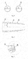
- fig.1 shows a schematic side view of the device
- fig.2 - a schematic top view of the device
- fig. 3 schematically presented seats of the inlet channel and of the outlet channel located next to each other, with the ventricular assist device not shown in the figure
- fig. 4 a schematic longitudinal section of the connector
- fig. 5 a close-up of the side view of the nut mounted on the connector with the shown protruding element of the connector
- fig. 6 - a cross section of the adjacent parts of the two-part nut
- fig. 7 - a longitudinal section of the nut
- fig. 8 - a transverse section of the perspective view of the nut screwed on the second end of the connector.
- a blood pump in the form of a pneumatic heart assist device 1 comprises a spherical cap 2 which has an air chamber 4 and a blood chamber 3 separated by a membrane mounted around the inside perimeter of the spherical cap 2.
- the blood chamber 3 of the spherical cap 2 has an inlet channel 5 for blood and an outlet channel 6 for blood, inside which channels 5, 6 there are circular seats 7, 8 for mounting mechanical valves regulating the flow of blood through the pump.
- To the inlet channel 5 and the outlet channel 6 are mounted connectors 9 with the first ends thereof, used for coupling the pump with cannulas connecting the pump with the circulatory system of a patient.
- the diameter D 1 of the seat 7 for the valve in the inlet channel 5 is smaller than the diameter D2 of the seat 8 for the valve in the outlet channel 6.
- the diameter D1 of the seat 7 is 20mm, whereas the diameter D2 of the seat 8 is 24mm.
- the invention also relates to embodiments where the diameter ratio D1 / D2 is between 0.75 and 0.92. The above difference in the diameters D1 and D2 of the seats 7 and 8 results in different sizes of the mechanical valves mounted in said seats.
- each connector 9 along the full working length thereof, except for the connecting section 10, where the connector 9 is mounted on the outlets of the inlet channel 5 and the outlet channel 6, is uniformly convergent towards the second end of said connector 9.
- the angle of the inside surfaces of the connectors 9 with reference to the connector axis is 4°.
- the invention also relates to embodiments where the angle is smaller than 5°.
- an external stop 11 On the external surface of the connector 9 at the second end thereof used for coupling with the cannula, there is an external stop 11 which allows to precisely determine the distance at which the cannula should be mounted on the second end of the connector 9.
- the connector 9 is coupled with the cannula, not shown in the drawing, by means of a two-part nut 12.
- the nut 12 consists of two elements interconnected by means of a form-fitting guide coupling 13 with longitudinal run with reference to the nut hole axis.
- the coupling of the elements of the nut 12 consists in that both halves are mounted on the cannula already mounted on the connector and connects by means of sliding mutually corresponding form-fitting elements of the guide coupling.
- the nut 12 coupled in this manner is fastened to the connector 9 by means of a screw fastening, which is shown in fig. 8 .
- a fastened screw element comprising, for example, two halfrings on which the nut 12 is screwed on.
- any useful form-fitting coupling could be used.
- the length of the nut 12 is smaller than the distance between the extreme end 14 of a coupling element of the connector 9, in this case a screw fastening corresponding with the nut and the second end of the connector 9.
Abstract

Description
- The subject of the invention is a blood pump, in particular a pneumatic ventricular assist device.
- The known pneumatic ventricular assist devices ( VAD ) are applied to support the hearts of patients with congestive heart failure. The known ventricular assist device, which is in practice a blood pump, comprises a spherical cap with a blood chamber and an air chamber separated by a membrane. The membrane is mounted around the inside perimeter of the spherical cap. The blood chamber of the spherical cap has an inlet channel for blood and an outlet channel for blood, which channels have circular seats for mounting valves regulating the blood flow through the pump. In the case of external ventricular assist devices mechanical, disc heart valves are applied. Connectors used for connecting the pump to cannulas joining the pump to the circulatory system of a patient are fixed to the inlet and outlet channels with first ends thereof. The pneumatic part of the spherical cap is connected to a generator making alternate pneumatic wave which stimulates alternate movement of the membrane located between the pneumatic part of the spherical cap and the blood chamber thereof. The alternate movement of the membrane results in the blood flowing through the device.
- In the known VAD systems the diameters of the seats in the inlet channel and the outlet channel are the same or the diameter of the inlet channel is larger than the diameter of the outlet channel. What is more, the connector along the working length thereof except for the connecting section has an inside channel whose cross-section is partially uniform and partially narrowing towards the second end which is used for connecting with the cannula.
- The example of a pneumatic ventricular assist device is known from the Polish utility model description no.
Ru. 63283 - The invention relates to a blood pump, in particular a pneumatic ventricular assist device comprising a spherical cap with an air chamber and a blood chamber separated by a membrane mounted around the inside perimeter of the spherical cap. The blood chamber of the spherical cap has an inlet channel for blood and an outlet channel for blood which channels have circular seats for mounting valves regulating the blood flow through the pump. Connectors used for connecting the pump to the cannulas joining the pump with the circulatory system of a patient are fastened to the inlet channel and the outlet channel with the first ends thereof. The essence of the invention is that the diameter of the seat for the valve in the inlet channel is smaller than the diameter of the seat for the valve in the outlet channel, whereas the inside channel of each connector along the full working length thereof is uniformly convergent towards the second end of said connector.
- In a preferred embodiment the ratio of the diameters of the seat in the inlet channel and the seat on the outlet channel is between 0.75 and 0.92, preferably 0.83.
- It is also advisable when the inside surfaces of the channels of the connectors are inclined in relation to the connector axis at an angle smaller than 5°, preferably 4°.
- It is also recommendable that the connector on the outside surface of the second end thereof provided for connecting to a cannula has an external stop which allows to precisely determine the distance at which the cannula should be mounted on the second end of the connector.
- It is also advisable when the connector is connected to the cannula with a two-part nut which may also be fixed on the connector by means of a screw fastening or a form-fitting coupling, which allows for the nut to be fastened to the cannula already mounted on the second end of the connector and significantly facilitates the assembly of the connection.
- It is also advisable when the length of the nut is smaller than the distance between the extreme end of a coupling element of the connector assigned to said nut and the second end of the connector, owing to this following appropriate mounting of the cannula on the second end of the connector and appropriate seating of the nut, a protruding part of the second end of the connector is visible through the transparent cannula. It allows to assess the correctness of the fastening of the nut and also allows to observe the area of the inflow and outflow of blood into the inlet connector and from the outlet connector during the operation of the device.
- It is also advantageous when the two parts of the nut are interconnected by means of a form-fitting guide coupling of longitudinal run with reference to the axis of the nut hole.
- The blood pump, in particular the pneumatic ventricular heart assist device according to the invention optimises the parameters of blood flow on the inlet and outlet of the device owing to the appropriate differentiation of diameters of the seats for valves in the inlet channel and the outlet channel, which results in the analogical differentiation of the size of the valves mounted in said seats and owing to the new shape of the inside channel of the device connectors. It allows to reduce the areas of stagnation with the speed of blood flow too low to ensure sufficient blood flush and to reduce the areas where the shear stress caused by turbulent flow have a hemolytic influence on blood. As a result a reduced risk of intravascular coagulation or thrombosis in the device was achieved. Moreover, turbulences in the area of valves were eliminated, which had an additional advantageous effect on the optimisation of the dynamics of the blood flow in the device with reference to the thrombosis risk. The construction of the coupling of the connector with the cannula ensures a safe connection with reference to the risk of uncoupling during operation, while being convenient for mounting and easily, repeatedly separable.
- The invention has been presented in greater detail in the following embodiment and in the enclosed drawing where
fig.1 shows a schematic side view of the device,fig.2 - a schematic top view of the device,fig. 3 - schematically presented seats of the inlet channel and of the outlet channel located next to each other, with the ventricular assist device not shown in the figure,fig. 4 - a schematic longitudinal section of the connector,fig. 5 - a close-up of the side view of the nut mounted on the connector with the shown protruding element of the connector,fig. 6 - a cross section of the adjacent parts of the two-part nut,fig. 7 - a longitudinal section of the nut, andfig. 8 - a transverse section of the perspective view of the nut screwed on the second end of the connector. - A blood pump in the form of a pneumatic
heart assist device 1 comprises aspherical cap 2 which has anair chamber 4 and ablood chamber 3 separated by a membrane mounted around the inside perimeter of thespherical cap 2. Theblood chamber 3 of thespherical cap 2 has aninlet channel 5 for blood and anoutlet channel 6 for blood, inside which channels 5, 6 there arecircular seats inlet channel 5 and theoutlet channel 6 are mountedconnectors 9 with the first ends thereof, used for coupling the pump with cannulas connecting the pump with the circulatory system of a patient. Thediameter D 1 of theseat 7 for the valve in theinlet channel 5 is smaller than the diameter D2 of theseat 8 for the valve in theoutlet channel 6. - In the described embodiment the diameter D1 of the
seat 7 is 20mm, whereas the diameter D2 of theseat 8 is 24mm. The invention also relates to embodiments where the diameter ratio D1 / D2 is between 0.75 and 0.92. The above difference in the diameters D1 and D2 of theseats - The inside channel of each
connector 9 along the full working length thereof, except for the connectingsection 10, where theconnector 9 is mounted on the outlets of theinlet channel 5 and theoutlet channel 6, is uniformly convergent towards the second end of saidconnector 9. In the presented embodiment the angle of the inside surfaces of theconnectors 9 with reference to the connector axis is 4°. The invention also relates to embodiments where the angle is smaller than 5°. - On the external surface of the
connector 9 at the second end thereof used for coupling with the cannula, there is anexternal stop 11 which allows to precisely determine the distance at which the cannula should be mounted on the second end of theconnector 9. - The
connector 9 is coupled with the cannula, not shown in the drawing, by means of a two-part nut 12. In the embodiment shown in the drawing thenut 12 consists of two elements interconnected by means of a form-fitting guide coupling 13 with longitudinal run with reference to the nut hole axis. The coupling of the elements of thenut 12 consists in that both halves are mounted on the cannula already mounted on the connector and connects by means of sliding mutually corresponding form-fitting elements of the guide coupling. Thenut 12 coupled in this manner is fastened to theconnector 9 by means of a screw fastening, which is shown infig. 8 . To achieve this on the external surface of theconnector 9 shown infig. 4 there is a fastened screw element comprising, for example, two halfrings on which thenut 12 is screwed on. Alternatively, instead of the screw fastening any useful form-fitting coupling could be used. - The length of the
nut 12 is smaller than the distance between theextreme end 14 of a coupling element of theconnector 9, in this case a screw fastening corresponding with the nut and the second end of theconnector 9. After appropriate mounting of the cannula on the second end of theconnector 9 and screwing on thenut 12 there is a visible protrudingelement 15 of the second end of theconnector 9.
Claims (9)
- A blood pump, in particular a pneumatic ventricular assist device comprising a spherical cap with an air chamber and a blood chamber separated by a membrane mounted around the perimeter of the spherical cap, where the blood chamber of the cap has an inlet channel for blood and an outlet channel for blood, where said channels have circular seats for mounting valves regulating the flow of blood through the pump, to the inlet and outlet channel are fastened connectors with the first ends thereof used for joining the pump to cannulas connecting the pump to the circulatory system of a patient, characterised in that the diameter ( D1 ) of the seat ( 7 ) for the valve in the inlet channel ( 5 ) is smaller than the diameter ( D2 ) of the seat ( 8 ) for the valve in the outlet channel ( 6 ), whereas the inside channel of each connector ( 9 ) along the full working length thereof is uniformly convergent towards the second end of said connector ( 9 ).
- The pump according to claim 1, characterised in that the diameter ratio ( D1 / D2 ) of the seat ( 7 ) of the inlet channel ( 5 ) and of the seat ( 8 ) of the outlet channel ( 6 ) is between 0.75 and 0.92, preferably it is 0.83.
- The pump according to claim 1, characterised in that the internal surfaces of the channels of the connectors ( 9 ) are inclined with reference to the axis of the connector ( 9 ) at an angle smaller than 5°, preferably 4°.
- The pump according to claim 1 or 2 or 3 characterised in that the connector ( 9 ) has an external stop ( 11 ) on the external surface of the second end thereof used for connecting with the cannula.
- The pump according to one of the above claims characterised in that the connector ( 9 ) is fastened to the cannula by means of a two-part nut ( 12 ).
- The pump according to claim 5 characterised in that the nut (12 ) is mounted on the connector ( 9 ) by means of a screw fastening.
- The pump according to claim 5 characterised in that the nut ( 12 ) is mounted on the connector ( 9 ) by means of form-fitting coupling.
- The pump according to claim 5 or 6 or 7 characterised in that the length of the nut ( 12 ) is smaller than the distance between the extreme end ( 14 ) of the connecting element of the connector ( 9 ) for said nut ( 12 ) and the second end of the connector ( 9 ).
- The pump according to one of the claims 5 to 8 characterised in that the two elements of the nut ( 12 ) are interconnected by means of a form-fitting guide coupling ( 13 ) with longitudinal run with reference to the axis of the nut hole ( 12 ).
Priority Applications (1)
| Application Number | Priority Date | Filing Date | Title |
|---|---|---|---|
| PL11183484T PL2491966T3 (en) | 2011-02-28 | 2011-09-30 | Blood pump, in particular a pneumatic ventricular assist device |
Applications Claiming Priority (1)
| Application Number | Priority Date | Filing Date | Title |
|---|---|---|---|
| PL394056A PL217321B1 (en) | 2011-02-28 | 2011-02-28 | Blood pump, especially pneumatic ventricular assist device |
Publications (2)
| Publication Number | Publication Date |
|---|---|
| EP2491966A1 true EP2491966A1 (en) | 2012-08-29 |
| EP2491966B1 EP2491966B1 (en) | 2013-12-25 |
Family
ID=45047561
Family Applications (1)
| Application Number | Title | Priority Date | Filing Date |
|---|---|---|---|
| EP11183484.2A Active EP2491966B1 (en) | 2011-02-28 | 2011-09-30 | Blood pump, in particular a pneumatic ventricular assist device |
Country Status (2)
| Country | Link |
|---|---|
| EP (1) | EP2491966B1 (en) |
| PL (2) | PL217321B1 (en) |
Cited By (4)
| Publication number | Priority date | Publication date | Assignee | Title |
|---|---|---|---|---|
| GB2555435A (en) * | 2016-10-27 | 2018-05-02 | Calon Cardio Tech Ltd | Cardiac pump |
| CN108653840A (en) * | 2017-03-31 | 2018-10-16 | 广东省心血管病研究所 | Cryptomere chamber lung auxiliary circulating equipment |
| TWI826960B (en) * | 2021-03-17 | 2023-12-21 | 美國商怡忠生命科學有限公司 | Blood pump device having endo-leak free aortic adapter assembly and method of device implantation |
| WO2024013720A1 (en) * | 2022-07-15 | 2024-01-18 | Vitalmex Internacional S.A. De C.V. | Ventricular assist devices and methods |
Citations (5)
| Publication number | Priority date | Publication date | Assignee | Title |
|---|---|---|---|---|
| US4167046A (en) * | 1977-12-12 | 1979-09-11 | Andros, Inc. | Blood pumping device |
| US4222127A (en) * | 1978-06-02 | 1980-09-16 | Donachy And Pierce | Blood pump and method of pumping blood |
| US20020165426A1 (en) * | 2001-04-20 | 2002-11-07 | Deutsches Zentrum Fur Luft-Und Raumfahrt E.V. | Left ventricular assist system |
| RU63283U1 (en) | 2006-11-27 | 2007-05-27 | Государственное образовательное учреждение высшего профессионального образования "Курский государственный технический университет" | MODEL OF RETAINING DIAMOND-ABRASIVE GRAIN IN ORGANIC BONDES OF THE GRINDING TOOL |
| PL63283Y1 (en) * | 2004-11-11 | 2007-07-31 | Fundacja Rozwoju Kardiochirurg | Pneumatic chamber of the heart assist device |
-
2011
- 2011-02-28 PL PL394056A patent/PL217321B1/en unknown
- 2011-09-30 EP EP11183484.2A patent/EP2491966B1/en active Active
- 2011-09-30 PL PL11183484T patent/PL2491966T3/en unknown
Patent Citations (5)
| Publication number | Priority date | Publication date | Assignee | Title |
|---|---|---|---|---|
| US4167046A (en) * | 1977-12-12 | 1979-09-11 | Andros, Inc. | Blood pumping device |
| US4222127A (en) * | 1978-06-02 | 1980-09-16 | Donachy And Pierce | Blood pump and method of pumping blood |
| US20020165426A1 (en) * | 2001-04-20 | 2002-11-07 | Deutsches Zentrum Fur Luft-Und Raumfahrt E.V. | Left ventricular assist system |
| PL63283Y1 (en) * | 2004-11-11 | 2007-07-31 | Fundacja Rozwoju Kardiochirurg | Pneumatic chamber of the heart assist device |
| RU63283U1 (en) | 2006-11-27 | 2007-05-27 | Государственное образовательное учреждение высшего профессионального образования "Курский государственный технический университет" | MODEL OF RETAINING DIAMOND-ABRASIVE GRAIN IN ORGANIC BONDES OF THE GRINDING TOOL |
Cited By (6)
| Publication number | Priority date | Publication date | Assignee | Title |
|---|---|---|---|---|
| GB2555435A (en) * | 2016-10-27 | 2018-05-02 | Calon Cardio Tech Ltd | Cardiac pump |
| CN108653840A (en) * | 2017-03-31 | 2018-10-16 | 广东省心血管病研究所 | Cryptomere chamber lung auxiliary circulating equipment |
| CN108653840B (en) * | 2017-03-31 | 2019-08-20 | 广东省心血管病研究所 | Cryptomere chamber lung auxiliary circulating equipment |
| TWI826960B (en) * | 2021-03-17 | 2023-12-21 | 美國商怡忠生命科學有限公司 | Blood pump device having endo-leak free aortic adapter assembly and method of device implantation |
| WO2024013720A1 (en) * | 2022-07-15 | 2024-01-18 | Vitalmex Internacional S.A. De C.V. | Ventricular assist devices and methods |
| EP4306160A3 (en) * | 2022-07-15 | 2024-02-28 | Vitalmex Internacional S.A. DE C.V. | Ventricular assist devices and methods |
Also Published As
| Publication number | Publication date |
|---|---|
| EP2491966B1 (en) | 2013-12-25 |
| PL217321B1 (en) | 2014-07-31 |
| PL2491966T3 (en) | 2014-05-30 |
| PL394056A1 (en) | 2012-09-10 |
Similar Documents
| Publication | Publication Date | Title |
|---|---|---|
| EP2491966B1 (en) | Blood pump, in particular a pneumatic ventricular assist device | |
| CN106989183A (en) | Flow control valve | |
| CN104394970B (en) | A kind of equipment for generation of nano bubble | |
| EP1681520A3 (en) | fluid valve | |
| EP2607712A1 (en) | Pump housing with an interior for holding a pump rotor | |
| WO2016005803A3 (en) | Ventricular assist device | |
| EP2517739A2 (en) | Blood pump, in particular implantable pneumatic heart assist device | |
| CN104043162B (en) | Preventing thrombosis venous detaining needle and the method for preventing thrombosis thereof | |
| WO2008144398A3 (en) | Pump module for use in a medical fluid dispensing system | |
| EP2251574A3 (en) | Flow rate regulating valve for heating and cooling assemblies | |
| WO2020016438A1 (en) | Feed line for a pump unit of a cardiac assistance system, cardiac assistance system and method for producing a feed line for a pump unit of a cardiac assistance system | |
| EP2589415A3 (en) | Flow shaper for use in corridor sprinkler | |
| EP2592273A3 (en) | Hydraulic pump assembly | |
| WO2006120464A3 (en) | Biomechanical probe | |
| EP2942070A3 (en) | Hose line for fresh and/or consumed dialysis fluid | |
| EP2378127A3 (en) | Flow guiding component with pump and fitting | |
| EP2617443B1 (en) | Pressure actuated single-lumen blood pumping device | |
| EP2022517B1 (en) | Blood tube system for extracorporeal applications such as dialysis devices, comprising an expansion chamber providing a small air-blood contact surface | |
| WO2008146144A3 (en) | Kit for the extracorporeal treatment of a biological fluid of a patient, and unit provided with said kit | |
| CN207621551U (en) | A kind of gas distribution equipment | |
| EP2712636A1 (en) | A pediatric heart assist pump | |
| WO2011152983A8 (en) | Fluid flow contour control using flow resistance | |
| CN202418731U (en) | Four-way diaphragm valve | |
| CN106456931B (en) | A kind of device and method of lower resistance valve | |
| EP2151280A3 (en) | Pump device and method for operating a pump device |
Legal Events
| Date | Code | Title | Description |
|---|---|---|---|
| PUAI | Public reference made under article 153(3) epc to a published international application that has entered the european phase |
Free format text: ORIGINAL CODE: 0009012 |
|
| AK | Designated contracting states |
Kind code of ref document: A1 Designated state(s): AL AT BE BG CH CY CZ DE DK EE ES FI FR GB GR HR HU IE IS IT LI LT LU LV MC MK MT NL NO PL PT RO RS SE SI SK SM TR |
|
| 17P | Request for examination filed |
Effective date: 20130225 |
|
| GRAP | Despatch of communication of intention to grant a patent |
Free format text: ORIGINAL CODE: EPIDOSNIGR1 |
|
| INTG | Intention to grant announced |
Effective date: 20130719 |
|
| GRAS | Grant fee paid |
Free format text: ORIGINAL CODE: EPIDOSNIGR3 |
|
| GRAA | (expected) grant |
Free format text: ORIGINAL CODE: 0009210 |
|
| RAP1 | Party data changed (applicant data changed or rights of an application transferred) |
Owner name: FUNDACJA ROZWOJU KARDIOCHIRURGII IM. PROF. ZBIGNIE |
|
| AK | Designated contracting states |
Kind code of ref document: B1 Designated state(s): AL AT BE BG CH CY CZ DE DK EE ES FI FR GB GR HR HU IE IS IT LI LT LU LV MC MK MT NL NO PL PT RO RS SE SI SK SM TR |
|
| REG | Reference to a national code |
Ref country code: GB Ref legal event code: FG4D |
|
| REG | Reference to a national code |
Ref country code: CH Ref legal event code: EP |
|
| REG | Reference to a national code |
Ref country code: AT Ref legal event code: REF Ref document number: 646222 Country of ref document: AT Kind code of ref document: T Effective date: 20140115 |
|
| REG | Reference to a national code |
Ref country code: IE Ref legal event code: FG4D |
|
| REG | Reference to a national code |
Ref country code: DE Ref legal event code: R096 Ref document number: 602011004330 Country of ref document: DE Effective date: 20140213 |
|
| PG25 | Lapsed in a contracting state [announced via postgrant information from national office to epo] |
Ref country code: NO Free format text: LAPSE BECAUSE OF FAILURE TO SUBMIT A TRANSLATION OF THE DESCRIPTION OR TO PAY THE FEE WITHIN THE PRESCRIBED TIME-LIMIT Effective date: 20140325 Ref country code: FI Free format text: LAPSE BECAUSE OF FAILURE TO SUBMIT A TRANSLATION OF THE DESCRIPTION OR TO PAY THE FEE WITHIN THE PRESCRIBED TIME-LIMIT Effective date: 20131225 Ref country code: HR Free format text: LAPSE BECAUSE OF FAILURE TO SUBMIT A TRANSLATION OF THE DESCRIPTION OR TO PAY THE FEE WITHIN THE PRESCRIBED TIME-LIMIT Effective date: 20131225 Ref country code: SE Free format text: LAPSE BECAUSE OF FAILURE TO SUBMIT A TRANSLATION OF THE DESCRIPTION OR TO PAY THE FEE WITHIN THE PRESCRIBED TIME-LIMIT Effective date: 20131225 Ref country code: LT Free format text: LAPSE BECAUSE OF FAILURE TO SUBMIT A TRANSLATION OF THE DESCRIPTION OR TO PAY THE FEE WITHIN THE PRESCRIBED TIME-LIMIT Effective date: 20131225 |
|
| REG | Reference to a national code |
Ref country code: NL Ref legal event code: VDEP Effective date: 20131225 |
|
| REG | Reference to a national code |
Ref country code: LT Ref legal event code: MG4D |
|
| PG25 | Lapsed in a contracting state [announced via postgrant information from national office to epo] |
Ref country code: RS Free format text: LAPSE BECAUSE OF FAILURE TO SUBMIT A TRANSLATION OF THE DESCRIPTION OR TO PAY THE FEE WITHIN THE PRESCRIBED TIME-LIMIT Effective date: 20131225 Ref country code: LV Free format text: LAPSE BECAUSE OF FAILURE TO SUBMIT A TRANSLATION OF THE DESCRIPTION OR TO PAY THE FEE WITHIN THE PRESCRIBED TIME-LIMIT Effective date: 20131225 |
|
| REG | Reference to a national code |
Ref country code: PL Ref legal event code: T3 |
|
| PG25 | Lapsed in a contracting state [announced via postgrant information from national office to epo] |
Ref country code: EE Free format text: LAPSE BECAUSE OF FAILURE TO SUBMIT A TRANSLATION OF THE DESCRIPTION OR TO PAY THE FEE WITHIN THE PRESCRIBED TIME-LIMIT Effective date: 20131225 Ref country code: IS Free format text: LAPSE BECAUSE OF FAILURE TO SUBMIT A TRANSLATION OF THE DESCRIPTION OR TO PAY THE FEE WITHIN THE PRESCRIBED TIME-LIMIT Effective date: 20140425 Ref country code: BE Free format text: LAPSE BECAUSE OF FAILURE TO SUBMIT A TRANSLATION OF THE DESCRIPTION OR TO PAY THE FEE WITHIN THE PRESCRIBED TIME-LIMIT Effective date: 20131225 |
|
| PG25 | Lapsed in a contracting state [announced via postgrant information from national office to epo] |
Ref country code: RO Free format text: LAPSE BECAUSE OF FAILURE TO SUBMIT A TRANSLATION OF THE DESCRIPTION OR TO PAY THE FEE WITHIN THE PRESCRIBED TIME-LIMIT Effective date: 20131225 Ref country code: CY Free format text: LAPSE BECAUSE OF FAILURE TO SUBMIT A TRANSLATION OF THE DESCRIPTION OR TO PAY THE FEE WITHIN THE PRESCRIBED TIME-LIMIT Effective date: 20131225 Ref country code: NL Free format text: LAPSE BECAUSE OF FAILURE TO SUBMIT A TRANSLATION OF THE DESCRIPTION OR TO PAY THE FEE WITHIN THE PRESCRIBED TIME-LIMIT Effective date: 20131225 Ref country code: PT Free format text: LAPSE BECAUSE OF FAILURE TO SUBMIT A TRANSLATION OF THE DESCRIPTION OR TO PAY THE FEE WITHIN THE PRESCRIBED TIME-LIMIT Effective date: 20140428 Ref country code: SK Free format text: LAPSE BECAUSE OF FAILURE TO SUBMIT A TRANSLATION OF THE DESCRIPTION OR TO PAY THE FEE WITHIN THE PRESCRIBED TIME-LIMIT Effective date: 20131225 Ref country code: ES Free format text: LAPSE BECAUSE OF FAILURE TO SUBMIT A TRANSLATION OF THE DESCRIPTION OR TO PAY THE FEE WITHIN THE PRESCRIBED TIME-LIMIT Effective date: 20131225 Ref country code: CZ Free format text: LAPSE BECAUSE OF FAILURE TO SUBMIT A TRANSLATION OF THE DESCRIPTION OR TO PAY THE FEE WITHIN THE PRESCRIBED TIME-LIMIT Effective date: 20131225 |
|
| REG | Reference to a national code |
Ref country code: DE Ref legal event code: R097 Ref document number: 602011004330 Country of ref document: DE |
|
| PG25 | Lapsed in a contracting state [announced via postgrant information from national office to epo] |
Ref country code: DK Free format text: LAPSE BECAUSE OF FAILURE TO SUBMIT A TRANSLATION OF THE DESCRIPTION OR TO PAY THE FEE WITHIN THE PRESCRIBED TIME-LIMIT Effective date: 20131225 |
|
| PLBE | No opposition filed within time limit |
Free format text: ORIGINAL CODE: 0009261 |
|
| STAA | Information on the status of an ep patent application or granted ep patent |
Free format text: STATUS: NO OPPOSITION FILED WITHIN TIME LIMIT |
|
| 26N | No opposition filed |
Effective date: 20140926 |
|
| REG | Reference to a national code |
Ref country code: DE Ref legal event code: R097 Ref document number: 602011004330 Country of ref document: DE Effective date: 20140926 |
|
| PG25 | Lapsed in a contracting state [announced via postgrant information from national office to epo] |
Ref country code: LU Free format text: LAPSE BECAUSE OF FAILURE TO SUBMIT A TRANSLATION OF THE DESCRIPTION OR TO PAY THE FEE WITHIN THE PRESCRIBED TIME-LIMIT Effective date: 20140930 Ref country code: MC Free format text: LAPSE BECAUSE OF FAILURE TO SUBMIT A TRANSLATION OF THE DESCRIPTION OR TO PAY THE FEE WITHIN THE PRESCRIBED TIME-LIMIT Effective date: 20131225 |
|
| REG | Reference to a national code |
Ref country code: CH Ref legal event code: PL |
|
| PG25 | Lapsed in a contracting state [announced via postgrant information from national office to epo] |
Ref country code: SI Free format text: LAPSE BECAUSE OF FAILURE TO SUBMIT A TRANSLATION OF THE DESCRIPTION OR TO PAY THE FEE WITHIN THE PRESCRIBED TIME-LIMIT Effective date: 20131225 |
|
| REG | Reference to a national code |
Ref country code: IE Ref legal event code: MM4A |
|
| PG25 | Lapsed in a contracting state [announced via postgrant information from national office to epo] |
Ref country code: CH Free format text: LAPSE BECAUSE OF NON-PAYMENT OF DUE FEES Effective date: 20140930 Ref country code: LI Free format text: LAPSE BECAUSE OF NON-PAYMENT OF DUE FEES Effective date: 20140930 |
|
| PG25 | Lapsed in a contracting state [announced via postgrant information from national office to epo] |
Ref country code: IE Free format text: LAPSE BECAUSE OF NON-PAYMENT OF DUE FEES Effective date: 20140930 |
|
| PG25 | Lapsed in a contracting state [announced via postgrant information from national office to epo] |
Ref country code: SM Free format text: LAPSE BECAUSE OF FAILURE TO SUBMIT A TRANSLATION OF THE DESCRIPTION OR TO PAY THE FEE WITHIN THE PRESCRIBED TIME-LIMIT Effective date: 20131225 |
|
| PG25 | Lapsed in a contracting state [announced via postgrant information from national office to epo] |
Ref country code: IT Free format text: LAPSE BECAUSE OF FAILURE TO SUBMIT A TRANSLATION OF THE DESCRIPTION OR TO PAY THE FEE WITHIN THE PRESCRIBED TIME-LIMIT Effective date: 20131225 Ref country code: BG Free format text: LAPSE BECAUSE OF FAILURE TO SUBMIT A TRANSLATION OF THE DESCRIPTION OR TO PAY THE FEE WITHIN THE PRESCRIBED TIME-LIMIT Effective date: 20131225 Ref country code: GR Free format text: LAPSE BECAUSE OF FAILURE TO SUBMIT A TRANSLATION OF THE DESCRIPTION OR TO PAY THE FEE WITHIN THE PRESCRIBED TIME-LIMIT Effective date: 20140326 Ref country code: MT Free format text: LAPSE BECAUSE OF FAILURE TO SUBMIT A TRANSLATION OF THE DESCRIPTION OR TO PAY THE FEE WITHIN THE PRESCRIBED TIME-LIMIT Effective date: 20131225 |
|
| PG25 | Lapsed in a contracting state [announced via postgrant information from national office to epo] |
Ref country code: TR Free format text: LAPSE BECAUSE OF FAILURE TO SUBMIT A TRANSLATION OF THE DESCRIPTION OR TO PAY THE FEE WITHIN THE PRESCRIBED TIME-LIMIT Effective date: 20131225 Ref country code: HU Free format text: LAPSE BECAUSE OF FAILURE TO SUBMIT A TRANSLATION OF THE DESCRIPTION OR TO PAY THE FEE WITHIN THE PRESCRIBED TIME-LIMIT; INVALID AB INITIO Effective date: 20110930 |
|
| REG | Reference to a national code |
Ref country code: FR Ref legal event code: PLFP Year of fee payment: 6 |
|
| REG | Reference to a national code |
Ref country code: FR Ref legal event code: PLFP Year of fee payment: 7 |
|
| PG25 | Lapsed in a contracting state [announced via postgrant information from national office to epo] |
Ref country code: MK Free format text: LAPSE BECAUSE OF FAILURE TO SUBMIT A TRANSLATION OF THE DESCRIPTION OR TO PAY THE FEE WITHIN THE PRESCRIBED TIME-LIMIT Effective date: 20131225 |
|
| REG | Reference to a national code |
Ref country code: FR Ref legal event code: PLFP Year of fee payment: 8 |
|
| PG25 | Lapsed in a contracting state [announced via postgrant information from national office to epo] |
Ref country code: AL Free format text: LAPSE BECAUSE OF FAILURE TO SUBMIT A TRANSLATION OF THE DESCRIPTION OR TO PAY THE FEE WITHIN THE PRESCRIBED TIME-LIMIT Effective date: 20131225 |
|
| PGFP | Annual fee paid to national office [announced via postgrant information from national office to epo] |
Ref country code: TR Payment date: 20180905 Year of fee payment: 8 |
|
| PGFP | Annual fee paid to national office [announced via postgrant information from national office to epo] |
Ref country code: DE Payment date: 20190925 Year of fee payment: 9 Ref country code: FR Payment date: 20190924 Year of fee payment: 9 |
|
| PGFP | Annual fee paid to national office [announced via postgrant information from national office to epo] |
Ref country code: AT Payment date: 20190926 Year of fee payment: 9 |
|
| GBPC | Gb: european patent ceased through non-payment of renewal fee |
Effective date: 20190930 |
|
| PG25 | Lapsed in a contracting state [announced via postgrant information from national office to epo] |
Ref country code: GB Free format text: LAPSE BECAUSE OF NON-PAYMENT OF DUE FEES Effective date: 20190930 |
|
| REG | Reference to a national code |
Ref country code: DE Ref legal event code: R079 Ref document number: 602011004330 Country of ref document: DE Free format text: PREVIOUS MAIN CLASS: A61M0001100000 Ipc: A61M0060000000 |
|
| REG | Reference to a national code |
Ref country code: DE Ref legal event code: R119 Ref document number: 602011004330 Country of ref document: DE |
|
| REG | Reference to a national code |
Ref country code: AT Ref legal event code: MM01 Ref document number: 646222 Country of ref document: AT Kind code of ref document: T Effective date: 20200930 |
|
| PG25 | Lapsed in a contracting state [announced via postgrant information from national office to epo] |
Ref country code: DE Free format text: LAPSE BECAUSE OF NON-PAYMENT OF DUE FEES Effective date: 20210401 Ref country code: FR Free format text: LAPSE BECAUSE OF NON-PAYMENT OF DUE FEES Effective date: 20200930 |
|
| PG25 | Lapsed in a contracting state [announced via postgrant information from national office to epo] |
Ref country code: AT Free format text: LAPSE BECAUSE OF NON-PAYMENT OF DUE FEES Effective date: 20200930 |
|
| PGFP | Annual fee paid to national office [announced via postgrant information from national office to epo] |
Ref country code: PL Payment date: 20230925 Year of fee payment: 13 |