EP2505179A1 - Transfer guard systems and methods - Google Patents
Transfer guard systems and methods Download PDFInfo
- Publication number
- EP2505179A1 EP2505179A1 EP20120154641 EP12154641A EP2505179A1 EP 2505179 A1 EP2505179 A1 EP 2505179A1 EP 20120154641 EP20120154641 EP 20120154641 EP 12154641 A EP12154641 A EP 12154641A EP 2505179 A1 EP2505179 A1 EP 2505179A1
- Authority
- EP
- European Patent Office
- Prior art keywords
- reservoir
- vial
- needle
- fluidic media
- interior volume
- Prior art date
- Legal status (The legal status is an assumption and is not a legal conclusion. Google has not performed a legal analysis and makes no representation as to the accuracy of the status listed.)
- Granted
Links
- 238000012546 transfer Methods 0.000 title claims abstract description 121
- 238000000034 method Methods 0.000 title claims description 76
- 238000001802 infusion Methods 0.000 claims abstract description 64
- 239000007788 liquid Substances 0.000 claims abstract description 11
- 239000012530 fluid Substances 0.000 claims description 33
- 230000007246 mechanism Effects 0.000 claims description 33
- 239000012528 membrane Substances 0.000 claims description 7
- NOESYZHRGYRDHS-UHFFFAOYSA-N insulin Chemical compound N1C(=O)C(NC(=O)C(CCC(N)=O)NC(=O)C(CCC(O)=O)NC(=O)C(C(C)C)NC(=O)C(NC(=O)CN)C(C)CC)CSSCC(C(NC(CO)C(=O)NC(CC(C)C)C(=O)NC(CC=2C=CC(O)=CC=2)C(=O)NC(CCC(N)=O)C(=O)NC(CC(C)C)C(=O)NC(CCC(O)=O)C(=O)NC(CC(N)=O)C(=O)NC(CC=2C=CC(O)=CC=2)C(=O)NC(CSSCC(NC(=O)C(C(C)C)NC(=O)C(CC(C)C)NC(=O)C(CC=2C=CC(O)=CC=2)NC(=O)C(CC(C)C)NC(=O)C(C)NC(=O)C(CCC(O)=O)NC(=O)C(C(C)C)NC(=O)C(CC(C)C)NC(=O)C(CC=2NC=NC=2)NC(=O)C(CO)NC(=O)CNC2=O)C(=O)NCC(=O)NC(CCC(O)=O)C(=O)NC(CCCNC(N)=N)C(=O)NCC(=O)NC(CC=3C=CC=CC=3)C(=O)NC(CC=3C=CC=CC=3)C(=O)NC(CC=3C=CC(O)=CC=3)C(=O)NC(C(C)O)C(=O)N3C(CCC3)C(=O)NC(CCCCN)C(=O)NC(C)C(O)=O)C(=O)NC(CC(N)=O)C(O)=O)=O)NC(=O)C(C(C)CC)NC(=O)C(CO)NC(=O)C(C(C)O)NC(=O)C1CSSCC2NC(=O)C(CC(C)C)NC(=O)C(NC(=O)C(CCC(N)=O)NC(=O)C(CC(N)=O)NC(=O)C(NC(=O)C(N)CC=1C=CC=CC=1)C(C)C)CC1=CN=CN1 NOESYZHRGYRDHS-UHFFFAOYSA-N 0.000 description 36
- 239000000463 material Substances 0.000 description 26
- 102000004877 Insulin Human genes 0.000 description 18
- 108090001061 Insulin Proteins 0.000 description 18
- 229940125396 insulin Drugs 0.000 description 18
- 238000003780 insertion Methods 0.000 description 16
- 230000037431 insertion Effects 0.000 description 16
- WQZGKKKJIJFFOK-GASJEMHNSA-N Glucose Natural products OC[C@H]1OC(O)[C@H](O)[C@@H](O)[C@@H]1O WQZGKKKJIJFFOK-GASJEMHNSA-N 0.000 description 15
- 239000008103 glucose Substances 0.000 description 15
- 239000000853 adhesive Substances 0.000 description 11
- 230000001070 adhesive effect Effects 0.000 description 11
- 238000004891 communication Methods 0.000 description 11
- 239000003814 drug Substances 0.000 description 9
- 239000004033 plastic Substances 0.000 description 9
- 229920003023 plastic Polymers 0.000 description 9
- 239000010410 layer Substances 0.000 description 8
- 239000008280 blood Substances 0.000 description 7
- 210000004369 blood Anatomy 0.000 description 7
- 239000002131 composite material Substances 0.000 description 7
- 229940079593 drug Drugs 0.000 description 7
- 239000011521 glass Substances 0.000 description 7
- 238000004519 manufacturing process Methods 0.000 description 7
- 230000013011 mating Effects 0.000 description 7
- 239000002184 metal Substances 0.000 description 7
- 239000005341 toughened glass Substances 0.000 description 6
- 206010012601 diabetes mellitus Diseases 0.000 description 5
- 230000009471 action Effects 0.000 description 4
- 230000008569 process Effects 0.000 description 4
- 238000005728 strengthening Methods 0.000 description 4
- 239000000758 substrate Substances 0.000 description 4
- 239000012491 analyte Substances 0.000 description 3
- 230000008878 coupling Effects 0.000 description 3
- 238000010168 coupling process Methods 0.000 description 3
- 238000005859 coupling reaction Methods 0.000 description 3
- 238000007726 management method Methods 0.000 description 3
- 230000002441 reversible effect Effects 0.000 description 3
- 230000000472 traumatic effect Effects 0.000 description 3
- 238000011282 treatment Methods 0.000 description 3
- 238000013022 venting Methods 0.000 description 3
- 208000017667 Chronic Disease Diseases 0.000 description 2
- 108090000790 Enzymes Proteins 0.000 description 2
- 102000004190 Enzymes Human genes 0.000 description 2
- 108060003393 Granulin Proteins 0.000 description 2
- 230000004888 barrier function Effects 0.000 description 2
- -1 but not limited to Substances 0.000 description 2
- 201000010099 disease Diseases 0.000 description 2
- 208000037265 diseases, disorders, signs and symptoms Diseases 0.000 description 2
- 229920001971 elastomer Polymers 0.000 description 2
- 229940088598 enzyme Drugs 0.000 description 2
- 238000005429 filling process Methods 0.000 description 2
- 238000012986 modification Methods 0.000 description 2
- 230000004048 modification Effects 0.000 description 2
- 238000012544 monitoring process Methods 0.000 description 2
- 229920000642 polymer Polymers 0.000 description 2
- 238000012545 processing Methods 0.000 description 2
- 238000010926 purge Methods 0.000 description 2
- 230000001105 regulatory effect Effects 0.000 description 2
- 230000004044 response Effects 0.000 description 2
- 239000005060 rubber Substances 0.000 description 2
- 229920000089 Cyclic olefin copolymer Polymers 0.000 description 1
- 239000004713 Cyclic olefin copolymer Substances 0.000 description 1
- 108010015776 Glucose oxidase Proteins 0.000 description 1
- 239000004366 Glucose oxidase Substances 0.000 description 1
- 208000019693 Lung disease Diseases 0.000 description 1
- 206010028980 Neoplasm Diseases 0.000 description 1
- FAPWRFPIFSIZLT-UHFFFAOYSA-M Sodium chloride Chemical compound [Na+].[Cl-] FAPWRFPIFSIZLT-UHFFFAOYSA-M 0.000 description 1
- 239000012790 adhesive layer Substances 0.000 description 1
- 239000012472 biological sample Substances 0.000 description 1
- 210000001124 body fluid Anatomy 0.000 description 1
- 239000010839 body fluid Substances 0.000 description 1
- 229920005557 bromobutyl Polymers 0.000 description 1
- 201000011510 cancer Diseases 0.000 description 1
- 238000010276 construction Methods 0.000 description 1
- 235000015872 dietary supplement Nutrition 0.000 description 1
- 238000012377 drug delivery Methods 0.000 description 1
- 230000009977 dual effect Effects 0.000 description 1
- 230000000694 effects Effects 0.000 description 1
- 238000005516 engineering process Methods 0.000 description 1
- 230000002708 enhancing effect Effects 0.000 description 1
- 230000007613 environmental effect Effects 0.000 description 1
- 238000009472 formulation Methods 0.000 description 1
- 229940116332 glucose oxidase Drugs 0.000 description 1
- 235000019420 glucose oxidase Nutrition 0.000 description 1
- 230000036571 hydration Effects 0.000 description 1
- 238000006703 hydration reaction Methods 0.000 description 1
- 230000003100 immobilizing effect Effects 0.000 description 1
- 239000007943 implant Substances 0.000 description 1
- 238000001746 injection moulding Methods 0.000 description 1
- 208000014674 injury Diseases 0.000 description 1
- 230000003993 interaction Effects 0.000 description 1
- 230000000670 limiting effect Effects 0.000 description 1
- 230000007774 longterm Effects 0.000 description 1
- 238000003754 machining Methods 0.000 description 1
- 239000000203 mixture Substances 0.000 description 1
- 238000003032 molecular docking Methods 0.000 description 1
- 238000000465 moulding Methods 0.000 description 1
- 230000003287 optical effect Effects 0.000 description 1
- 238000004806 packaging method and process Methods 0.000 description 1
- 230000002093 peripheral effect Effects 0.000 description 1
- 229920001296 polysiloxane Polymers 0.000 description 1
- 238000004382 potting Methods 0.000 description 1
- 238000003825 pressing Methods 0.000 description 1
- 239000000047 product Substances 0.000 description 1
- 230000002829 reductive effect Effects 0.000 description 1
- 230000000717 retained effect Effects 0.000 description 1
- 239000000523 sample Substances 0.000 description 1
- 238000007789 sealing Methods 0.000 description 1
- 229920002379 silicone rubber Polymers 0.000 description 1
- 239000004945 silicone rubber Substances 0.000 description 1
- 239000011780 sodium chloride Substances 0.000 description 1
- 238000003860 storage Methods 0.000 description 1
- 239000000126 substance Substances 0.000 description 1
- 229920003051 synthetic elastomer Polymers 0.000 description 1
- 239000005061 synthetic rubber Substances 0.000 description 1
- 238000012360 testing method Methods 0.000 description 1
- 230000008733 trauma Effects 0.000 description 1
- XLYOFNOQVPJJNP-UHFFFAOYSA-N water Substances O XLYOFNOQVPJJNP-UHFFFAOYSA-N 0.000 description 1
- 238000003466 welding Methods 0.000 description 1
Images


Classifications
-
- A—HUMAN NECESSITIES
- A61—MEDICAL OR VETERINARY SCIENCE; HYGIENE
- A61J—CONTAINERS SPECIALLY ADAPTED FOR MEDICAL OR PHARMACEUTICAL PURPOSES; DEVICES OR METHODS SPECIALLY ADAPTED FOR BRINGING PHARMACEUTICAL PRODUCTS INTO PARTICULAR PHYSICAL OR ADMINISTERING FORMS; DEVICES FOR ADMINISTERING FOOD OR MEDICINES ORALLY; BABY COMFORTERS; DEVICES FOR RECEIVING SPITTLE
- A61J1/00—Containers specially adapted for medical or pharmaceutical purposes
- A61J1/14—Details; Accessories therefor
- A61J1/20—Arrangements for transferring or mixing fluids, e.g. from vial to syringe
- A61J1/2089—Containers or vials which are to be joined to each other in order to mix their contents
-
- A—HUMAN NECESSITIES
- A61—MEDICAL OR VETERINARY SCIENCE; HYGIENE
- A61J—CONTAINERS SPECIALLY ADAPTED FOR MEDICAL OR PHARMACEUTICAL PURPOSES; DEVICES OR METHODS SPECIALLY ADAPTED FOR BRINGING PHARMACEUTICAL PRODUCTS INTO PARTICULAR PHYSICAL OR ADMINISTERING FORMS; DEVICES FOR ADMINISTERING FOOD OR MEDICINES ORALLY; BABY COMFORTERS; DEVICES FOR RECEIVING SPITTLE
- A61J1/00—Containers specially adapted for medical or pharmaceutical purposes
- A61J1/14—Details; Accessories therefor
- A61J1/20—Arrangements for transferring or mixing fluids, e.g. from vial to syringe
- A61J1/2096—Combination of a vial and a syringe for transferring or mixing their contents
-
- A—HUMAN NECESSITIES
- A61—MEDICAL OR VETERINARY SCIENCE; HYGIENE
- A61M—DEVICES FOR INTRODUCING MEDIA INTO, OR ONTO, THE BODY; DEVICES FOR TRANSDUCING BODY MEDIA OR FOR TAKING MEDIA FROM THE BODY; DEVICES FOR PRODUCING OR ENDING SLEEP OR STUPOR
- A61M5/00—Devices for bringing media into the body in a subcutaneous, intra-vascular or intramuscular way; Accessories therefor, e.g. filling or cleaning devices, arm-rests
- A61M5/14—Infusion devices, e.g. infusing by gravity; Blood infusion; Accessories therefor
- A61M5/142—Pressure infusion, e.g. using pumps
- A61M5/14244—Pressure infusion, e.g. using pumps adapted to be carried by the patient, e.g. portable on the body
- A61M5/14248—Pressure infusion, e.g. using pumps adapted to be carried by the patient, e.g. portable on the body of the skin patch type
-
- A—HUMAN NECESSITIES
- A61—MEDICAL OR VETERINARY SCIENCE; HYGIENE
- A61M—DEVICES FOR INTRODUCING MEDIA INTO, OR ONTO, THE BODY; DEVICES FOR TRANSDUCING BODY MEDIA OR FOR TAKING MEDIA FROM THE BODY; DEVICES FOR PRODUCING OR ENDING SLEEP OR STUPOR
- A61M5/00—Devices for bringing media into the body in a subcutaneous, intra-vascular or intramuscular way; Accessories therefor, e.g. filling or cleaning devices, arm-rests
- A61M5/14—Infusion devices, e.g. infusing by gravity; Blood infusion; Accessories therefor
- A61M5/142—Pressure infusion, e.g. using pumps
- A61M5/145—Pressure infusion, e.g. using pumps using pressurised reservoirs, e.g. pressurised by means of pistons
- A61M5/1452—Pressure infusion, e.g. using pumps using pressurised reservoirs, e.g. pressurised by means of pistons pressurised by means of pistons
- A61M5/1456—Pressure infusion, e.g. using pumps using pressurised reservoirs, e.g. pressurised by means of pistons pressurised by means of pistons with a replaceable reservoir comprising a piston rod to be moved into the reservoir, e.g. the piston rod is part of the removable reservoir
-
- A—HUMAN NECESSITIES
- A61—MEDICAL OR VETERINARY SCIENCE; HYGIENE
- A61J—CONTAINERS SPECIALLY ADAPTED FOR MEDICAL OR PHARMACEUTICAL PURPOSES; DEVICES OR METHODS SPECIALLY ADAPTED FOR BRINGING PHARMACEUTICAL PRODUCTS INTO PARTICULAR PHYSICAL OR ADMINISTERING FORMS; DEVICES FOR ADMINISTERING FOOD OR MEDICINES ORALLY; BABY COMFORTERS; DEVICES FOR RECEIVING SPITTLE
- A61J1/00—Containers specially adapted for medical or pharmaceutical purposes
- A61J1/14—Details; Accessories therefor
- A61J1/20—Arrangements for transferring or mixing fluids, e.g. from vial to syringe
- A61J1/2003—Accessories used in combination with means for transfer or mixing of fluids, e.g. for activating fluid flow, separating fluids, filtering fluid or venting
- A61J1/2006—Piercing means
- A61J1/201—Piercing means having one piercing end
-
- A—HUMAN NECESSITIES
- A61—MEDICAL OR VETERINARY SCIENCE; HYGIENE
- A61J—CONTAINERS SPECIALLY ADAPTED FOR MEDICAL OR PHARMACEUTICAL PURPOSES; DEVICES OR METHODS SPECIALLY ADAPTED FOR BRINGING PHARMACEUTICAL PRODUCTS INTO PARTICULAR PHYSICAL OR ADMINISTERING FORMS; DEVICES FOR ADMINISTERING FOOD OR MEDICINES ORALLY; BABY COMFORTERS; DEVICES FOR RECEIVING SPITTLE
- A61J1/00—Containers specially adapted for medical or pharmaceutical purposes
- A61J1/14—Details; Accessories therefor
- A61J1/20—Arrangements for transferring or mixing fluids, e.g. from vial to syringe
- A61J1/2003—Accessories used in combination with means for transfer or mixing of fluids, e.g. for activating fluid flow, separating fluids, filtering fluid or venting
- A61J1/2006—Piercing means
- A61J1/2013—Piercing means having two piercing ends
-
- A—HUMAN NECESSITIES
- A61—MEDICAL OR VETERINARY SCIENCE; HYGIENE
- A61J—CONTAINERS SPECIALLY ADAPTED FOR MEDICAL OR PHARMACEUTICAL PURPOSES; DEVICES OR METHODS SPECIALLY ADAPTED FOR BRINGING PHARMACEUTICAL PRODUCTS INTO PARTICULAR PHYSICAL OR ADMINISTERING FORMS; DEVICES FOR ADMINISTERING FOOD OR MEDICINES ORALLY; BABY COMFORTERS; DEVICES FOR RECEIVING SPITTLE
- A61J1/00—Containers specially adapted for medical or pharmaceutical purposes
- A61J1/14—Details; Accessories therefor
- A61J1/20—Arrangements for transferring or mixing fluids, e.g. from vial to syringe
- A61J1/2003—Accessories used in combination with means for transfer or mixing of fluids, e.g. for activating fluid flow, separating fluids, filtering fluid or venting
- A61J1/2068—Venting means
- A61J1/2075—Venting means for external venting
-
- A—HUMAN NECESSITIES
- A61—MEDICAL OR VETERINARY SCIENCE; HYGIENE
- A61M—DEVICES FOR INTRODUCING MEDIA INTO, OR ONTO, THE BODY; DEVICES FOR TRANSDUCING BODY MEDIA OR FOR TAKING MEDIA FROM THE BODY; DEVICES FOR PRODUCING OR ENDING SLEEP OR STUPOR
- A61M5/00—Devices for bringing media into the body in a subcutaneous, intra-vascular or intramuscular way; Accessories therefor, e.g. filling or cleaning devices, arm-rests
- A61M5/14—Infusion devices, e.g. infusing by gravity; Blood infusion; Accessories therefor
- A61M5/142—Pressure infusion, e.g. using pumps
- A61M5/14244—Pressure infusion, e.g. using pumps adapted to be carried by the patient, e.g. portable on the body
- A61M2005/14268—Pressure infusion, e.g. using pumps adapted to be carried by the patient, e.g. portable on the body with a reusable and a disposable component
-
- Y—GENERAL TAGGING OF NEW TECHNOLOGICAL DEVELOPMENTS; GENERAL TAGGING OF CROSS-SECTIONAL TECHNOLOGIES SPANNING OVER SEVERAL SECTIONS OF THE IPC; TECHNICAL SUBJECTS COVERED BY FORMER USPC CROSS-REFERENCE ART COLLECTIONS [XRACs] AND DIGESTS
- Y10—TECHNICAL SUBJECTS COVERED BY FORMER USPC
- Y10T—TECHNICAL SUBJECTS COVERED BY FORMER US CLASSIFICATION
- Y10T29/00—Metal working
- Y10T29/49—Method of mechanical manufacture
- Y10T29/494—Fluidic or fluid actuated device making
Definitions
- Embodiments of the present invention generally relate to systems and methods for transferring fluidic media and, in specific embodiments, to systems and methods for assisted filling of the reservoirs used in infusion pumps carried by patients suffering certain diseases including diabetes.
- certain chronic diseases may be treated by delivering a medication or other substance to the body of a patient.
- diabetes is a chronic disease that is commonly treated by delivering defined amounts of insulin to a patient at appropriate times.
- manually operated syringes and insulin pens have been employed for delivering insulin to a patient.
- modern systems have been designed to include programmable pumps for delivering controlled amounts of medication to a patient.
- External pump type delivery devices have been configured in external devices, which connect to a patient, and have been configured in implantable devices, which are implanted inside of the body of a patient.
- External pump type delivery devices include devices designed for use in a stationary location, such as a hospital, a clinic, or the like, and further include devices configured for ambulatory or portable use, such as devices designed to be carried by a patient, or the like.
- External pump-type delivery devices may contain reservoirs of fluidic media, such as, but is not limited to, insulin. In typical known arrangements, for example as shown in FIG.
- an external pump-type delivery device includes a reservoir in the form of a tube having a shoulder portion at the other end merging into a narrow neck for connection of the reservoir to tubing to receive the fluid media.
- a drive mechanism advances the plunger head within the parallel bore tube to expel the fluid medicine via the tubing.
- the reservoir When the reservoir is empty it is disengaged from the drive mechanism and tubing, removed from the pump and replaced by a new full reservoir.
- the latter contains a pierceable septum, and the tubing connects via a needle that pierces the septum of a new reservoir when it is installed in the pump.
- it may be desired to refill the reservoir thus requiring a system for transferring fluidic media from an external source, for example a vial to a reservoir for use in an infusion pump.
- External pump-type delivery devices may be connected in fluid flow communication to a patient or user-patient, for example, through suitable hollow tubing.
- the hollow tubing may be connected to a hollow needle that is designed to pierce the skin of the patient and to deliver fluidic media there through.
- the hollow tubing may be connected directly to the patient as through a cannula, or the like.
- External pump-type delivery devices may be connected in fluid-flow communication to a patient-user, for example, through suitable hollow tubing.
- the hollow tubing may be connected to a hollow needle that is designed to pierce the patient-user's skin and deliver an infusion medium to the patient-user.
- the hollow tubing may be connected directly to the patient-user as or through a cannula or set of micro-needles.
- a manual insertion of the needle into the patient-user can be somewhat traumatic to the user-patient.
- insertion mechanisms have been made to assist the insertion of a needle into the user-patient, whereby a needle is forced by a spring to move quickly from a retracted position into an extended position. As the needle is moved into the extended position, the needle is quickly forced through the skin of the user-patient in a single, relatively abrupt motion that can be less traumatic to certain user-patients as compared to a slower, manual insertion of a needle.
- Pump-type delivery devices can allow accurate doses of insulin to be calculated and delivered automatically to a patient-user at any time during the day or night. Furthermore, when used in conjunction with glucose sensors or monitors, insulin pumps may be automatically controlled to provide appropriate doses of infusion medium at appropriate times of need, based on sensed or monitored levels of blood glucose.
- Pump-type delivery devices have become an important aspect of modern medical treatments of various types of medical conditions, such as diabetes. As pump technologies improve and as doctors and patient-users become more familiar with such devices, the popularity of external medical infusion pump treatment increases and is expected to increase substantially over the next decade.
- the present invention provides a system for transferring fluidic media may include, but is not limited to, a transfer guard, a handle, and optionally also a casing.
- the transfer guard provides a fluid path from a vial to a reservoir.
- the handle may be configured to be operatively engagable to a plunger arm connected to a plunger head arranged for movement in an axial direction of the reservoir.
- the plunger head is axially movable within the reservoir to draw fluid in via the fluid path when it is retracted.
- the plunger arm is able to move in the axial direction relative to the reservoir to move the plunger head in the axial direction within the reservoir.
- the casing if provided, encloses the rear of the reservoir while at the same time allowing movement of the plunger arm.
- the handle may be configured to cover at least a portion of the casing,
- the transfer guard and the handle may be configured such that fluidic media is transferred from the vial to the reservoir when the handle is operatively engaged to the plunger arm and the handle is moved relative to the axial direction relative to the reservoir.
- the casing may have an opening for allowing the handle to operatively engage the plunger arm.
- the handle may include an engagement portion configured for pivotal movement to operatively engage and disengage the plunger arm.
- the handle may include a slide adapted to cause the pivotal movement of the engagement portion to operatively engage and disengage the plunger arm.
- the slide may be adapted to move at least between a first position and a second position.
- the engagement portion may be configured to engage the plunger arm when the slide is moved to the first position. In this first position the slide holds the engagement portion in engagement with the plunger arm.
- the engagement portion may be configured to disengage the plunger arm when the slide is moved to the second position.
- the engagement portion may have an extension.
- the plunger arm may have an aperture for receiving the extension when the engagement portion of the handle operatively engages the plunger arm.
- the extension of the engagement portion may be for extending through an opening in the casing to operatively engage the aperture in the plunger arm and for allowing the extension of the engagement portion to move along the opening as the plunger arm is moved by the handle.
- the transfer guard may have an end for mating with the reservoir.
- the end may comprise a body configured to envelop the reservoir.
- the body may be adapted to allow fluidic media in the reservoir to be viewable through the body in a case where the reservoir is connected to the end of the transfer guard and the reservoir contains fluidic media.
- the body may have an opening for allowing fluidic media in the reservoir to be viewable and for allowing a user-patient to provide further support to the reservoir during use of the system.
- the body may have one or more fill lines for measuring a volume of fluidic media in the reservoir.
- the invention provides a system for transferring fluidic media including a transfer guard having a chamber.
- the transfer guard may include, but is not limited to, a first needle, a second needle, and an air flow control mechanism.
- the first needle connects the interior volume of the vial to the interior volume of the reservoir to provide a fluid flow path from the interior volume of the vial to the interior volume of the reservoir.
- the second needle connects the chamber and the interior volume of the vial.
- the air flow control mechanism is arranged within the chamber and configured to allow air to flow in one direction in a case where the second needle connects the chamber and the vial and the plunger head is moved within the reservoir to transfer fluidic media from the interior volume of the vial to the interior volume of the reservoir.
- the air flow control mechanism may be configured to allow the chamber to communicate with atmosphere to equalize pressure relative to atmosphere in the interior volume of the vial in a case where the second needle connects the chamber and the vial and the plunger head is moved within the reservoir to transfer fluidic media from the interior volume of the vial to the interior volume of the reservoir.
- the air flow control mechanism may comprise a membrane configured to allow air to flow in one direction.
- the air flow control mechanism may comprise a valve for example at least one of an umbrella valve and a duckbill valve configured to allow air to flow in one direction.
- the invention provides a method of making a system for transferring fluidic media including any one of or combination of: (i) providing a transfer guard for providing a fluid path from a vial to a reservoir; (ii) configuring a handle to be operatively engagable to a plunger arm connected to a plunger head arranged for movement in an axial direction of the reservoir; (iii) configuring a casing to allow the plunger arm to move in the axial direction relative to the reservoir to move the plunger head in the axial direction within the reservoir; (iv) configuring the handle to cover at least a portion of the casing; and (v) configuring the transfer guard and the handle such that fluidic media is transferred from the vial to the reservoir in a case where the handle is operatively engaged to the plunger arm and the handle is moved in the axial direction relative to the reservoir.
- a system for transferring fluidic media may include, but is not limited to, a support structure, a first needle, a second needle, and an air flow control mechanism.
- the support structure may have a chamber.
- the support structure may include, but is not limited to a first adapter and a second adapter.
- the first adapter may be adapted to be mated to a vial having an interior volume containing fluidic media.
- the second adapter may be adapted to be mated to a reservoir having an interior volume for containing fluidic media and a plunger head arranged for movement within the reservoir.
- the first needle may be for connecting the interior volume of the vial to the interior volume of the reservoir to provide a fluid flow path from the interior volume of the vial to the interior volume of the reservoir.
- the second needle may be for connecting the chamber and the interior volume of the vial.
- the air flow control mechanism may be arranged within the chamber and configured to allow air to flow in one direction in a case where the second needle connects the chamber and the vial and the plunger head is moved within the reservoir to transfer fluidic media from the interior volume of the vial to the interior volume of the reservoir.
- At least a portion of the first needle may be concentrically arranged within at least a portion of the second needle.
- the first needle and the second needle may share a common axis.
- An axis of the first needle and an axis of the second needle may be parallel to each other.
- the axis of the first needle may be offset from the axis of the second needle.
- the air flow control mechanism may be adapted to allow the chamber to communicate with atmosphere to equalize pressure relative to atmosphere in the interior volume of the vial in a case where the second needle connects the chamber and the vial and the plunger head is moved within the reservoir to transfer fluidic media from the interior volume of the vial to the interior volume of the reservoir.
- the air flow control mechanism may comprise a membrane.
- the air flow control mechanism may comprise a valve for example at least one of an umbrella valve and a duckbill valve. The valve may be moveable at least between a first position and a second position.
- the chamber may be for communicating with atmosphere in a case where the valve is in the second position and the fluid flow path is established.
- the second adapter may comprise a body configured to envelop the reservoir.
- the body may be adapted to allow fluidic media in the reservoir to be viewable through the body in a case where the reservoir is connected to the second adapter and the reservoir contains fluidic media.
- the body may have an opening for allowing fluidic media in the reservoir to be viewable and for allowing a user-patient to provide further support to the reservoir during use of the system.
- the body may have one or more fill lines for measuring a volume of fluidic media in the reservoir.
- a method of making a system for transferring fluidic media may include but is not limited to, any one of or combination of: (i) supporting a support structure having a chamber, the support structure comprising: a first adapter adapted to be mated to a vial having an interior volume containing fluidic media; and a second adapter adapted to be mated to a reservoir having an interior volume for containing fluidic media and a plunger head arranged for movement within the reservoir; (ii) connecting the interior volume of the vial to the interior volume of the reservoir to provide a fluid flow path from the interior volume of the vial to the interior volume of the reservoir with a first needle; (iii) connecting the chamber and the interior volume of the vial with a second needle; and (iv) arranging an air flow control mechanism within the chamber and configuring the air flow control mechanism to allow air to flow in one direction in a case where the second needle connects the chamber and the vial and the plunger head is moved within the reservoir to transfer fluidic media from the interior volume of the vial
- a refill station for refilling the infusible liquid reservoir for an infusion pump, the station comprising a vial containing a supply of the infusible liquid, a transfer guard having a first adapter adapted to mate with the vial, a second adapter for connection to the reservoir and a first needle extended from the vial through the transfer guard to project from the second adapter, a tubular handle having a transverse engagement finger displaceable radially within the handle and a manually operable slide on said tubular handle to move and hold the engagement finger in a radially inwardly displaced position.
- FIG. 1 illustrates a generalized representation of a system in accordance with an embodiment of the present invention
- FIG. 2 illustrates an example of a system in accordance with an embodiment of the present invention
- FIG. 3 illustrates an example of a delivery device in accordance with an embodiment of the present invention
- FIG. 4 illustrates a delivery device in accordance with an embodiment of the present invention
- FIG. 5A illustrates a durable portion of a delivery device in accordance with an embodiment of the present invention
- FIG. 5B illustrates a section view of a durable portion of a delivery device in accordance with an embodiment of the present invention
- FIG. 5C illustrates a section view of a durable portion of a delivery device in accordance with an embodiment of the present invention
- FIG. 6A illustrates a disposable portion of a delivery device in accordance with an embodiment of the present invention
- FIG. 6B illustrates a section view of a disposable portion of a delivery device in accordance with an embodiment of the present invention
- FIG. 6C illustrates a section view of a disposable portion of a delivery device in accordance with an embodiment of the present invention
- FIG. 7 is a cross-section of a portion of a medical device in accordance with an embodiment of the present invention.
- FIG. 8A is a cross-section of a portion of a medical device in accordance with an embodiment of the present invention.
- FIG. 8B is a cross-section of a portion of a medical device in accordance with an embodiment of the present invention.
- FIG. 8C is a cross-section of a portion of a medical device in accordance with an embodiment of the present invention.
- FIG. 9 illustrates a medical device in accordance with an embodiment of the present invention.
- FIG. 10 illustrates a portion of a medical device in accordance with an embodiment of the present invention
- FIG. 11 illustrates a portion of a medical device in accordance with an embodiment of the present invention
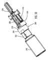
- FIG. 12 illustrates a portion of a medical device in accordance with an embodiment of the present invention
- FIG. 13 is a cross-section of a portion of a medical device in accordance with an embodiment of the present invention.
- FIG. 14A is a cross-section of a portion of a medical device in accordance with an embodiment of the present invention.
- FIG. 14B is a cross-section of a portion of a medical device in accordance with an embodiment of the present invention.
- FIG. 14C is a cross-section of a portion of a medical device in accordance with an embodiment of the present invention.
- FIG. 15 illustrates a flowchart for using a medical device in accordance with an embodiment of the present invention
- FIG. 16A illustrates a portion of a medical device in accordance with an embodiment of the present invention
- FIG. 16B illustrates a portion of a medical device in accordance with an embodiment of the present invention.
- FIG. 17 is a cross-section of a portion of a medical device in accordance with an embodiment of the present invention.
- FIG. 1 illustrates a generalized representation of a system 10 in which embodiments of the present invention may be used.
- the system 10 includes a delivery device 12.
- the system 10 may further include a sensing device 14, a command control device (CCD) 16, and a computer 18.
- the delivery device 12 and the sensing device 14 may be secured at desired locations on the body 5 of a patient or user-patient 7.
- the locations at which the delivery device 12 and the sensing device 14 are secured to the body 5 of the user-patient 7 in FIG. 1 are provided only as representative, non-limiting, examples.
- the system 10, the delivery device 12, the sensing device 14, the CCD 16, and computer 18 may be similar to those described in the following U.S. Patent Applications that were assigned to the assignee of the present invention, where each of following patent applications is incorporated herein by reference in its entirety: (i) U.S. Patent Application Serial No. 11/211,095, filed August 23, 2005 , “Infusion Device And Method With Disposable Portion”; (ii) U.S. Patent Application Serial No. 11/515,225, filed September 01, 2006 , "Infusion Medium Delivery Device And Method With Drive Device For Driving Plunger In Reservoir”; (iii) U.S. Patent Application Serial No.
- the delivery device 12 may be configured to deliver fluidic media to the body 5 of the user-patient 7.
- the fluidic media may include a liquid, a fluid, a gel, or the like.
- the fluidic media may include a medicine or a drug for treating a disease or a medical condition.
- fluidic media may include insulin for treating diabetes, or may include a drug for treating pain, cancer, a pulmonary disorder, HIV, or the like.
- the fluidic media may include a nutritional supplement, a dye, a tracing medium, a saline medium, a hydration medium, or the like.
- the sensing device 14 may include a sensor, a monitor, or the like, for providing sensor data or monitor data.
- the sensing device 14 may be configured to sense a condition of the user-patient 7.
- the sensing device 14 may include electronics and enzymes reactive to a biological condition, such as a blood glucose level, or the like, of the user-patient 7.
- the sensing device 14 may be secured to the body 5 of the user-patient 7 or embedded in the body 5 of the user-patient 7 at a location that is remote from the location at which the delivery device 12 is secured to the body 5 of the user-patient 7. In various other arrangements, the sensing device 14 may be incorporated within the delivery device 12. Alternatively the sensing device 14 may be separate and apart from the delivery device, and may be, for example, part of the CCD 16. In such arrangements, the sensing device 14 may be configured to receive a biological sample, analyte, or the like, to measure a condition of the user-patient 7.
- the sensing device 14 and/or the delivery device 12 may utilize a closed-loop system.
- Examples of sensing devices and/or delivery devices utilizing closed-loop systems may be found at, but are not limited to, the following references: (i) U.S. Patent No. 6,088,608 , entitled “Electrochemical Sensor And Integrity Tests Therefor”; (ii) U.S. Patent No. 6,119,028 , entitled “Implantable Enzyme-Based Monitoring Systems Having Improved Longevity Due To Improved Exterior Surfaces"; (iii) U.S. Patent No. 6,589,229 , entitled “Implantable Enzyme-Based Monitoring Systems Adapted for Long Term Use”; (iv) U.S. Patent No.
- the sensing device 14 may be configured to sense a condition of the user-patient 7, such as, but not limited to, blood glucose level, or the like.
- the delivery device 12 may be configured to deliver fluidic media in response to the condition sensed by the sensing device 14.
- the sensing device 14 may continue to sense a new condition of the user-patient, allowing the delivery device 12 to deliver fluidic media continuously in response to the new condition sensed by the sensing device 14 indefinitely.
- the sensing device 14 and/or the delivery device 12 may be configured to utilize the closed-loop system only for a portion of the day, for example only when the user-patient is asleep or awake.
- Each of the delivery device 12, the sensing device 14, the CCD 16, and the computer 18 may include transmitter, receiver, or transceiver electronics that allow for communication with other components of the system 10.
- the sensing device 14 may be configured to transmit sensor data or monitor data to the delivery device 12.
- the sensing device 14 may also be configured to communicate with the CCD 16.
- the delivery device 12 may include electronics and software that are configured to analyze sensor data and to deliver fluidic media to the body 5 of the user-patient 7 based on the sensor data and/or preprogrammed delivery routines.
- the CCD 16 and the computer 18 may include electronics and other components configured to perform processing, delivery routine storage, and to control the delivery device 12. By including control functions in the CCD 16 and/or the computer 18, the delivery device 12 may be made with more simplified electronics. However, in some arrangements, the delivery device 12 may include all control functions, and may operate without the CCD 16 and the computer 18.
- the CCD 16 may be a portable electronic device.
- the delivery device 12 and/or the sensing device 14 may be configured to transmit data to the CCD 16 and/or the computer 18 for display or processing of the data by the CCD 16 and/or the computer 18.
- the sensing device 14 may be integrated into the CCD 16. Such arrangements may allow the user-patient to monitor a condition by providing, for example, a sample of his or her blood to the sensing device 14 to assess his or her condition.
- the sensing device 14 and the CCD 16 may be for determining glucose levels in the blood and/or body fluids of the user-patient without the use of, or necessity of, a wire or cable connection between the delivery device 12 and the sensing device 14 and/or the CCD 16.
- the CCD 16 may be for providing information to the user-patient that facilitates the user-patient's subsequent use of a drug delivery system.
- the CCD 16 may provide information to the user-patient to allow the user-patient to determine the rate or dose of medication to be administered into the body of the user-patient.
- the CCD 16 may provide information to the delivery device 12 to control the rate or dose of medication administered into the body of the user-patient
- FIG. 2 illustrates an example of the system 10 which includes the delivery device 12 and the sensing device 14.
- the delivery device 12 includes a disposable housing 20, a durable housing 30, and a reservoir system 40.
- the delivery device 12 may further include an infusion path 50.
- a disposable portion of the delivery device 12 may include the disposable housing 20 and the reservoir system 40.
- the disposable portion of the delivery device 12 may be recommended for disposal after a specified number of uses.
- a durable portion of the delivery device 12 may include the durable housing 30, electronics (not shown in FIG. 2 ), a drive device having a motor and drive linkage (not shown in FIG. 2 ), and the like. Elements of the durable housing portion of the delivery device 12 are typically not contaminated from contact with the user-patient or fluidic media during normal operation of the delivery device 12 and, thus, may be retained for re-use with replaced disposable portions of the delivery device 12.
- the disposable housing 20 supports the reservoir system 40 and has a bottom surface (facing downward and into the page in FIG. 2 ) that is configured to secure to the body of a user-patient.
- An adhesive may be employed at an interface between the bottom surface of the disposable housing 20 and the skin of a user-patient to adhere the disposable housing 20 to the skin of the user-patient.
- the adhesive may be provided on the bottom surface of the disposable housing 20, with a peelable cover layer covering the adhesive material. In this manner, the cover layer may be peeled off to expose the adhesive material, and the adhesive side of the disposable housing 20 may be placed against the user-patient, for example against the skin of the user-patient.
- the delivery device 12 may be attached to the skin of the user-patient.
- the disposable housing 20 and/or the remaining portions of the delivery device 12 may be worn or otherwise attached on or underneath clothing of the user-patient.
- the delivery device 12 may be supported by any suitable manner, such as, but not limited to, on a belt, in a pocket, and the like.
- Representative examples of such delivery devices 12 may include, but is not limited to, the MiniMed Paradigm 522 Insulin Pump, MiniMed Paradigm 722 Insulin Pump, MiniMed Paradigm 515 Insulin Pump, MiniMed Paradigm 715 Insulin Pump, MiniMed Paradigm 512R Insulin Pump, MiniMed Paradigm 712R Insulin Pump, MiniMed 508 Insulin Pump, MiniMed 508R Insulin Pump, and any other derivatives thereof.
- the reservoir system 40 is configured for containing or holding fluidic media, such as, but not limited to insulin.
- the reservoir system 40 includes a hollow interior volume for receiving fluidic media, such as, but not limited to, a cylinder-shaped volume, a tubular-shaped volume, or the like.
- the reservoir system 40 may be provided as a cartridge or canister for containing fluidic media.
- the reservoir system 40 is able to be refilled with fluidic media.
- the reservoir system 40 is pre-filled with fluidic media.
- the reservoir system 40 may be supported by the disposable housing 20 in any suitable manner.
- the disposable housing 20 may be provided with projections or struts (not shown), or a trough feature (not shown), for holding the reservoir system 40.
- the reservoir system 40 may be supported by the disposable housing 20 in a manner that allows the reservoir system 40 to be removed from the disposable housing 20 and replaced with another reservoir.
- the reservoir system 40 may be secured to the disposable housing 20 by a suitable adhesive, a strap, or other coupling structure.
- the reservoir system 40 includes a port 41 for allowing fluidic media to flow into and/or flow out of the interior volume of the reservoir system 40.
- the infusion path 50 includes a connector 56, a tube 54, and a needle apparatus 52.
- the connector 56 of the infusion path 50 may be connectable to the port 41 of the reservoir system 40.
- the disposable housing 20 is configured with an opening near the port 41 of the reservoir system 40 for allowing the connector 56 of the infusion path 50 to be selectively connected to and disconnected from the port 41 of the reservoir system 40.
- the port 41 of the reservoir system 40 is covered with or supports a septum (not shown in FIG. 2 ), such as a self-sealing septum, or the like.
- the septum may be configured to prevent fluidic media from flowing out of the reservoir system 40 through the port 41 when the septum is not pierced.
- the connector 56 of the infusion path 50 includes a needle for piercing the septum covering the port 41 of the reservoir system 40 to allow fluidic media to flow out of the interior volume of the reservoir system 40.
- needle/septum connectors can be found in U.S. Patent Application Serial No. 10/328,393, filed December 22, 2003 , entitled “Reservoir Connector,” which is incorporated herein by reference in its entirety.
- non-septum connectors such as Luer locks, or the like may be used.
- the needle apparatus 52 of the infusion path 50 includes a needle that is able to puncture the skin of a user-patient.
- the tube 54 connects the connector 56 with the needle apparatus 52 and is hollow, such that the infusion path 50 is able to provide a path to allow for the delivery of fluidic media from the reservoir system 40 to the body of a user-patient.
- the durable housing 30 of the delivery device 12 may include a housing shell configured to mate with and secure to the disposable housing 20.
- the durable housing 30 and the disposable housing 20 may be provided with correspondingly shaped grooves, notches, tabs, or other suitable features, that allow the two parts to easily connect together, by manually pressing the two housings together, by twist or threaded connection, or other suitable manner of connecting the parts that is well known in the mechanical arts.
- the durable housing 30 and the disposable housing 20 may be connected to each other using a twist action.
- the durable housing 30 and the disposable housing 20 may be configured to be separable from each other when a sufficient force is applied to disconnect the two housings from each other.
- the disposable housing 20 and the durable housing 30 may be snapped together by friction fitting.
- a suitable seal such as an o-ring seal, may be placed along a peripheral edge of the durable housing 30 and/or the disposable housing 20, to provide a seal against water entering between the durable housing 30 and the disposable housing 20.
- the durable housing 30 of the delivery device 12 may support a drive device (not shown in FIG. 2 ), including a motor and a drive device linkage portion, for applying a force to fluidic media within the reservoir system 40 to force fluidic media out of the reservoir system 40 and into an infusion path, such as the infusion path 50, for delivery to a user-patient.
- a drive device (not shown in FIG. 2 ), including a motor and a drive device linkage portion, for applying a force to fluidic media within the reservoir system 40 to force fluidic media out of the reservoir system 40 and into an infusion path, such as the infusion path 50, for delivery to a user-patient.
- an electrically driven motor may be mounted within the durable housing 30 with appropriate linkage for operatively coupling the motor to a plunger arm (not shown in FIG. 2 ) connected to a plunger head (not shown in FIG. 2 ) that is within the reservoir system 40 and to drive the plunger head in a direction to force fluidic media out of the port 41 of the reservoir system 40
- the motor may be controllable to reverse direction to move the plunger arm and the plunger head to cause fluid to be drawn into the reservoir system 40 from a patient.
- the motor may be arranged within the durable housing 30 and the reservoir system 40 may be correspondingly arranged on the disposable housing 20, such that the operable engagement of the motor with the plunger head, through the appropriate linkage, occurs automatically upon the user-patient connecting the durable housing 30 with the disposable housing 20 of the delivery device 12.
- linkage and control structures may be found in U.S. Patent Application Serial No. 09/813,660, filed March 21,2001 , entitled "Control Tabs for Infusion Devices and Methods of Using the Same", which is incorporated herein by reference in its entirety.
- the durable housing 30 and the disposable housing 20 may be made of suitably rigid materials that maintain their shape, yet provide sufficient flexibility and resilience to effectively connect together and disconnect, as described above.
- the material of the disposable housing 20 may be selected for suitable compatibility with skin.
- the disposable housing 20 and the durable housing 30 of the delivery device 12 may be made of any suitable plastic, metal, composite material, or the like.
- the disposable housing 20 may be made of the same type of material or a different material relative to the durable housing 30.
- the disposable housing 20 and the durable housing 30 may be manufactured by injection molding or other molding processes, machining processes, or combinations thereof.
- the disposable housing 20 may be made of a relatively flexible material, such as a flexible silicone, plastic, rubber, synthetic rubber, or the like.
- a relatively flexible material such as a flexible silicone, plastic, rubber, synthetic rubber, or the like.
- the delivery device 12 is connected to the sensing device 14 through a connection element 17 of the sensing device 14.
- the sensing device 14 may include a sensor 15 that includes any suitable biological or environmental sensing device, depending upon a nature of a treatment to be administered by the delivery device 12.
- the sensor 15 may include a blood glucose sensor, or the like.
- the sensor 15 may include a continuous glucose sensor.
- the continuous glucose sensor may be implantable within the body of the user-patient. Alternatively, the continuous glucose sensor may be located externally, for example on the skin of the user-patient, or attached to clothing of the user-patient. In such arrangements, fluid may be drawn continually from the user-patient and sensed by the continuous glucose sensor.
- the continuous glucose sensor may be configured to sense and/or communicate with the CCD 16 continuously. Alternatively, the continuous glucose sensor may be configured to sense and/or communicate with the CCD 16 intermittently, for example sense glucose levels and transmit information every few minutes.
- the continuous glucose sensor may utilize glucose oxidase.
- the sensor 15 may be an external sensor that secures to the skin of a user-patient or may be an implantable sensor that is located in an implant site within the body of the user-patient. In further alternatives, the sensor may be included with as a part or along side the infusion cannula and/or needle, such as for example as shown in U.S. Patent Application Serial No. 11/149,119, filed June 8, 2005 , entitled “Dual Insertion Set", which is incorporated herein by reference in its entirety.
- the sensor 15 is an external sensor having a disposable needle pad that includes a needle for piercing the skin of the user-patient and enzymes and/or electronics reactive to a biological condition, such as blood glucose level or the like, of the user-patient.
- the delivery device 12 may be provided with sensor data from the sensor 15 secured to the user-patient at a site remote from the location at which the delivery device 12 is secured to the user-patient.
- FIG. 2 While the arrangement shown in FIG. 2 includes a sensor 15 connected by the connection element 17 for providing sensor data to sensor electronics (not shown in FIG. 2 ) located within the durable housing 30 of the delivery device 12, other arrangements may employ a sensor 15 located within the delivery device 12. Yet other arrangements may employ a sensor 15 having a transmitter for communicating sensor data by a wireless communication link with receiver electronics (not shown in FIG. 2 ) located within the durable housing 30 of the delivery device 12.
- a wireless connection between the sensor 15 and the receiver electronics within the durable housing 30 of the delivery device 12 may include a radio frequency (RF) connection, an optical connection, or another suitable wireless communication link.
- RF radio frequency
- the described arrangements need not employ the sensing device 14 and, instead, may provide fluidic media delivery functions without the use of sensor data.
- the disposable elements may be arranged on the disposable housing 20, while durable elements may be arranged within a separable durable housing 30.
- the disposable housing 20 may be separated from the durable housing 30, so that the disposable housing 20 may be disposed of in a proper manner.
- the durable housing 30 may then be mated with a new (unused) disposable housing 20 for further delivery operation with a user-patient.
- FIG. 3 illustrates an example of the delivery device 12.
- the delivery device 12 of FIG. 3 is similar to the delivery device 12 of FIG. 2 . While the delivery device 12 illustrated in FIG. 2 provides for the durable housing 30 to cover the reservoir system 40, the delivery device 12 of FIG. 3 provides for the durable housing 30 to secure to the disposable housing 20 without covering the reservoir system 40.
- the delivery device 12 illustrated in FIG. 3 includes the disposable housing 20, and the disposable housing 20 illustrated in FIG. 3 includes a base 21 and a reservoir retaining portion 24.
- the base 21 and reservoir retaining portion 24 may be formed as a single, unitary structure.
- the base 21 of the disposable housing 20 is configured to be secured to the body of a user-patient.
- the reservoir retaining portion 24 of the disposable housing 20 is configured to house the reservoir system 40.
- the reservoir retaining portion 24 of the disposable housing 20 may be configured to have an opening to allow for the port 41 of the reservoir system 40 to be accessed from outside of the reservoir retaining portion 24 while the reservoir system 40 is housed in the reservoir retaining portion 24.
- the durable housing 30 may be configured to be attachable to and detachable from the base 21 of the disposable housing 20.
- the delivery device 12 illustrated in FIG. 3 includes a plunger arm 60 that is connected to or that is connectable to a plunger head (not shown in FIG. 3 ) within the reservoir system 40.
- FIG. 4 illustrates another view of the delivery device 12 of FIG. 3 .
- the delivery device 12 illustrated in FIG. 4 includes the disposable housing 20, the durable housing 30, and the infusion path 50.
- the disposable housing 20 of FIG. 4 includes the base 21, the reservoir retaining portion 24, and a peelable cover layer 25.
- the peelable cover layer 25 may cover an adhesive material on the bottom surface 22 of the base 21.
- the peelable cover layer 25 may be configured to be peelable by a user-patient to expose the adhesive material on the bottom surface 22 of the base 21. There may be multiple adhesive layers on the bottom surface 22 of the base 21 that are separated by peelable layers.
- the infusion path 50 as illustrated in FIG. 4 includes the needle 58 rather than the connector 56, the tube 54, and the needle apparatus 52 as shown in FIG. 2 .
- the base 21 of the disposable housing 20 may be provided with an opening or pierceable wall in alignment with a tip of the needle 58, to allow the needle 58 to pass through the base 21 and into the skin of a user-patient under the base 21, when extended. In this manner, the needle 58 may be used to pierce the skin of the user-patient and deliver fluidic media to the user-patient.
- the needle 58 may be extended through a hollow cannula (not shown in FIG. 4 ), such that upon piercing the skin of the user-patient with the needle 58, an end of the hollow cannula is guided through the skin of the user-patient by the needle 58. Thereafter, the needle 58 may be removed, leaving the hollow cannula in place, with one end of the cannula located within the body of the user-patient and the other end of the cannula in fluid flow connection with fluidic media within the reservoir system 40, to convey pumped infusion media from the reservoir system 40 to the body of the user-patient.
- FIG. 5A illustrates a durable portion 8 of the delivery device 12 (refer to FIG. 3 ).
- FIG. 5B illustrates a section view of the durable portion 8.
- FIG. 5C illustrates another section view of the durable portion 8.
- the durable portion 8 includes the durable housing 30, and a drive device 80.
- the drive device 80 includes a motor 84 and a drive device linkage portion 82.
- the durable housing 30 may include an interior volume for housing the motor 84, the drive device linkage portion 82, other electronic circuitry, and a power source (not shown in FIGS. 5A, 5B, and 5C ).
- the durable housing 30 may be configured with an opening 32 for receiving a plunger arm 60 (refer to FIG. 3 ).
- the durable housing 30 may include one or more connection members 34, such as tabs, insertion holes, or the like, for connecting with the base 21 of the disposable housing 20 (refer to FIG. 3 ).
- FIG. 6A illustrates a disposable portion 9 of the delivery device 12 (refer to FIG. 3 ).
- FIG. 6B illustrates a section view of the disposable portion 9.
- FIG. 6C illustrates another section view of the disposable portion 9.
- the disposable portion 9 includes the disposable housing 20.
- the disposable housing 20 may include the base 21 and the reservoir retaining portion 24.
- the base 21 includes a top surface 23 having one or more connection members 26, such as tabs, grooves, or the like, for allowing connections with the one or more connection members 34 of the durable housing 30 (refer to FIG. 5B ).
- the reservoir system 40 is housed within the reservoir retaining portion 24 of the disposable housing 20, and the reservoir system 40 is configured to hold fluidic media.
- the plunger head 70 may be disposed at least partially within the reservoir system 40 and is moveable within the reservoir system 40 to allow fluidic media to fill into the reservoir system 40 and to force fluidic media out of the reservoir system 40.
- the plunger arm 60 is connected to or is connectable to the plunger head 70.
- a portion of the plunger arm 60 extends to outside of the reservoir retaining portion 24 of the disposable housing 20.
- the plunger arm 60 may have a mating portion for mating with the drive device linkage portion 82 of the drive device 80 (refer to FIG. 5C ).
- the durable housing 30 may be snap fitted onto the disposable housing 20, whereupon the drive device linkage portion 82 automatically engages the mating portion of the plunger arm 60.
- the motor 84 may be controlled to drive the drive device linkage portion 82 and, thus, move the plunger arm 60 to cause the plunger head 70 to move within the reservoir system 40.
- the plunger head 70 may be moved within the reservoir system 40 to force fluidic media from the reservoir system 40 and into the infusion path, so as to deliver fluidic media to the body of the user-patient.
- a user-patient may simply remove the durable housing 30 from the disposable housing 20, and replace the disposable portion 9, including the reservoir system 40, with a new disposable portion having a new reservoir.
- the durable housing 30 may be connected to the new disposable housing of the new disposable portion, and the delivery device including the new disposable portion may be secured to the skin of a user-patient, or otherwise attached to the user-patient.
- the reservoir system 40 may be refilled with fluidic media.
- the reservoir system 40 may be refilled while remaining within the reservoir retaining portion 24 (refer to FIG. 6B ) of the disposable housing 20.
- the reservoir system 40 may be replaced with a new reservoir (not shown), while the disposable housing 20 may be re-used with the new reservoir. In such cases the new reservoir may be inserted into the disposable portion 9.
- the delivery device 12 may include reservoir status circuitry (not shown), and the reservoir system 40 may include reservoir circuitry (not shown).
- the reservoir circuitry stores information such as, but not limited to, at least one of (i) an identification string identifying the reservoir system 40; (ii) a manufacturer of the reservoir system 40; (iii) contents of the reservoir system 40; and (iv) an amount of contents in the reservoir system 40.
- the delivery device 12 may include reservoir status circuitry (not shown), configured to read data from the reservoir circuitry when the reservoir system 40 is inserted into the disposable portion 9.
- the reservoir status circuitry may be configured to store data to the reservoir circuitry after at least some of the contents of the reservoir system 40 have been transferred out of the reservoir system 40, so as to update information in the reservoir circuitry related to an amount of contents still remaining in the reservoir system 40.
- the reservoir status circuitry may be configured to store data to the reservoir circuitry, to update information in the reservoir circuitry related to an amount of contents remaining in the reservoir system 40, when the reservoir system 40 is inserted into the disposable portion 9.
- the delivery device 12 may include the reservoir status circuitry (not shown) and the reservoir system 40 includes the reservoir circuitry (not shown), and the reservoir status circuitry selectively inhibits use of the delivery device 12 or selectively provides a warning signal based on information read by the reservoir status circuitry from the reservoir circuitry.
- FIGS. 7-8C illustrate a system 100 which may be used to refill the reservoir system 40 of FIGS. 2-6 with fluidic media.
- the system 100 may include features similar to, employed as an embodiment of, and/or used with the medical device systems discussed throughout the disclosure (e.g., delivery device 12 in FIGS. 1-6C ).
- the system 100 may include features similar or used with the arrangements of FIGS. 1-6C , it should be understood that the system 100 may also include some or all of the same features and operate in a manner similar to that shown and described in the embodiments of FIGS. 9-17 .
- some or all of the features shown in FIGS. 1-6C and 9-17 may be combined in various ways and included in the embodiments shown in FIGS. 7-8C .
- any of the features of the embodiments of FIGS. 7-8C may be combined or otherwise incorporated into any of the other embodiments of FIGS. 7-8C as well as any other embodiment herein discussed.
- the system 100 includes, but is not limited to, a vial 140, a transfer guard 160, and a reservoir 180.
- the vial 140 includes a septum 144 located at a port 142 of the vial 140.
- the vial 140 has an interior volume 145 containing fluidic media.
- the reservoir 180 (corresponding to the reservoir system 40 of FIG. 6 ) has an interior volume 185 for containing fluidic media.
- the reservoir 180 has a cylindrical walled body section of uniform diameter, merging at one end into a neck section port 182 of a reduced diameter. Within the neck section port 182 the reservoir 180 includes a septum 184 forming a pierceable closure at the end of the reservoir.
- the plunger head 190 is located within the body section of reservoir 180 and to be moveable axially within the reservoir 180 to expand or contract the interior volume 185 of the reservoir 180.
- the plunger head 190 may be attached to or integrated with a plunger arm 110.
- a handle (not shown) may be operatively connected to the plunger arm 110.
- the plunger head 190 includes at least one seal member 199, such as an o-ring, or the like, in contact with the wall of the body section of the reservoir 180.
- the interior volume 185 of the reservoir body 180 is bounded at one axial end by the seal member 199 and at the other axial end by the septum 184.
- the reservoir 180 has a chamber 187 located on an opposite side of the seal member 199 from the interior volume 185 of the reservoir 180.
- the seal member 199 prevents fluidic media from flowing from the interior volume 185 to the chamber 187 of the reservoir 180, while allowing movement of the plunger head 190 within the body section of the reservoir 180.
- the transfer guard 160 comprises a body 165 with first end 162 and a second end 170. Each end is configured as a docking station to mate respectively with the vial 140 and reservoir 185.
- the transfer guard 160 includes a needle 152, which passes through the transfer guard 160 and projects from both ends, thereby providing a fluid path from the interior volume 145 of the vial 140 to the interior volume 185 of the reservoir 180.
- the transfer guard 160 may be configured such that when the vial 140 is attached or otherwise mated to the transfer guard 160, the needle 152 automatically pierces the septum 144 of the vial 140.
- the transfer guard 160 may be further configured such that when the reservoir 180 is attached or otherwise mated to the transfer guard 160, the needle 152 automatically pierces the septum 184 of the reservoir 180.
- the transfer guard 160 creates a fluid path from the vial 140 to the reservoir 180 through the needle 152.
- the transfer guard 160 includes a second needle 156 although this second needle may be omitted.
- the second needle 156 is positioned to pierce the septum 144 of the vial 140 automatically when the vial 140 is connected to the transfer guard 160.
- one end of the second needle 156 extends to within a headspace 147 of the vial 140 above fluidic media within the interior volume 145 of the vial 140.
- the end of the second needle 156 may be in contact with fluidic media within the interior volume 145 of the vial 140 in a case where the transfer guard 160 is connected to the vial 140.
- the other end of the second needle 156 may be connected to a check valve 154, such as a one-way valve, or the like.
- the check valve 154 allows air to enter the interior volume 145 of the vial 140 through the second needle 156.
- the check valve 154 may also substantially prevent liquid from coming out of the vial 140 through the second needle 156 and/or the check valve 154.
- the second needle 156 therefore may allow for venting the headspace 147 or the interior volume 145 of the vial 140 to atmosphere to facilitate the transfer of fluidic media from the vial 140 to the reservoir 180.
- the first end 162 of the transfer guard 160 is configured to support or otherwise receive the vial 140 to attach or otherwise mate with the vial 140.
- a portion of the vial 140 e.g., portion corresponding to the port 142 of the vial 140
- the septum 144 of the vial 140 may be pierced by the needle 152 of the transfer guard 160 when the vial 140 is inserted into the first end 162 of the transfer guard 160.
- the first end 162 may be adapted to secure the vial 140 to the transfer guard 160 in any suitable manner known in the art, such as (but not limited to) friction fitting, snap-fitting, or the like.
- the first end 162 of the transfer guard 160 may include at least one tab 163, annular rib, or the like for securing the vial 140 within the first end 162 of the transfer guard 160 once the vial 140 is inserted in the first end 162 of the transfer guard 160.
- the second end 170 of the transfer guard located opposite the first end 162 supports or otherwise receives the reservoir 180 to which it attaches or otherwise mates.
- a portion of the reservoir 180 e.g., portion corresponding to the port 182 of the reservoir 180
- the septum 184 of the reservoir 180 is then pierced by the needle 152 of the transfer guard 160 as the reservoir 180 is inserted into the second end 170 of the transfer guard 160.
- the second end 170 may be adapted to secure the reservoir 180 to the transfer guard 160 in any suitable manner known in the art, such as (but not limited to) friction fitting, snap-fitting, or the like.
- the second end 170 of the transfer guard 160 includes a bayonet type connection.
- Such an arrangement could have one or more depressions or apertures 171 located within the second end 170 of the transfer guard 160, the port 182 portion of the reservoir 180 including one or more tabs 186 for inserting into the one or more apertures 171 located in the second end 170 of the transfer guard 160.
- the port 182 portion of the reservoir 180 would include at least one second tab 188 attached to each of the one or more tabs 186.
- the reservoir 180 and port 182 portion would then be configured to be rotatable, at least partially, about the second end 170 of the transfer guard 160 to secure the reservoir 180 to the transfer guard 160.
- the second end 170 of the transfer guard 160 could include one or more depressions 172 for receiving the at least one second tab 188 when the reservoir 180 and port 182 portion are rotated to secure the reservoir 180 to the transfer guard 160.
- the port 182 portion of the reservoir 180 may be inserted into the second end 170 of the transfer guard 160 so that the one or more tabs 186 fit into the apertures 171 and then rotated slightly until the at least one second tab 188 fits into place within the one or more depressions 172 to lock the reservoir 180 into the second end 170 of the transfer guard 160.
- connection between the first end 162 of the transfer guard 160 and the vial 140 may also be configured as a bayonet in the same manner as described above, so that the one or more tabs 163 fit into the one or more apertures and adapted to be rotatable slightly until the at least one second tab fits into place within the one or more depressions.
- the bayonet connections may be arranged to be respectively left and right rotation lockable so that a single part rotation of the transfer guard locks it both to the reservoir 180 and to the vial 140.
- FIGS. 7 and 8 In use the arrangement of FIGS. 7 and 8 is assembled by placing the port 182 of the reservoir into the second end 170 of the transfer guard. This causes the needle 152 to penetrate the septum 184 in the end of the reservoir 180. The transfer guard is then locked in place by a rotation through a small angle to engage the bayonet tabs and apertures 186, 188, 171, 182. Next the vial is lowered onto the transfer guard so that its neck enters the first end 162 of the transfer guard. This causes the other end of the needle 152 to penetrate the septum 144 in the end of the vial 140. Rotation of the vial then locks the vial in place on the transfer guard by operation of the bayonet tabs and apertures of the connections. When a second needle 156 is provided rotation is precluded , so a different locking mechanism must be used between the vial and the transfer guard 160.
- the plunger head 190 is pulled rearwardly within the reservoir 180. This increases the interior volume 185 of the reservoir 180 causing fluidic media to be sucked from the vial 140 into the reservoir via the needle 152. When a second needle 156 is provided this provides a passage for make-up air to enter the vial 140. Otherwise the pressure will equalize within the vial when the reservoir 180 is subsequently disconnected, or in the case of a flexible walled vial 140, on collapse of the vial.
- the plunger head When used in an infusion pump such as the delivery device 12 described with reference to FIGS. 1-6C above, the plunger head may be pulled rearwardly by means of the same drive mechanism as is used to expel fluid during infusion.
- the necessary reversal is obtained either within the mechanical gearing arrangements or by reversing the direction of rotation of the motor.
- FIGS. 9-17 illustrates a system 200 for transferring fluidic media, in accordance with a further embodiment of the present invention.
- the system 200 may be used with the medical device systems discussed throughout the disclosure (e.g., delivery device 12 in FIGS. 1-6C to fill the reservoir 40).
- the system 200 may include features similar to the systems discussed throughout the disclosure or employed as an embodiments of the systems (e.g., system 100 in FIGS. 7-8C ) discussed throughout the disclosure.
- some or all of the features shown in FIGS. 1-8C may be combined in various ways and included in the embodiments shown in FIG. 9-17 .
- any of the features of the embodiments of FIGS. 9-17 may be combined or otherwise incorporated into any of the other embodiments of FIGS. 9-17 as well as any other embodiment herein discussed.
- the system 200 is similar to the system 100 described with respect to FIGS. 7-8C .
- the system 200 includes, but is not limited to, a vial 240, a transfer guard 260, a reservoir 280, a plunger head 290, a plunger arm 210, a plunger arm casing 230, and a handle 220.
- a vial 240 for example, a transfer guard 260, a reservoir 280, a plunger head 290, a plunger arm 210, a plunger arm casing 230, and a handle 220.
- FIGS. 11-14B illustrate a reservoir 280, which may include features similar to or employed as an embodiment of the reservoir 180 (e.g., FIGS. 7 and 8C ), that may be employed in the system 200 according to various embodiments of the present invention.
- the reservoir 280 has an interior volume 285 for containing fluidic media.
- the reservoir 280 includes a septum 284 located at a port 282 of the reservoir 280.
- the reservoir 280 may be made of various suitable materials, including, but not limited to, glass, plastic, TGPAS® polymer (or any other cyclic olefin copolymer (or polymer)), or the like.
- the reservoir 280 may be of any suitable shape and/or size and may be adapted to hold any volume of fluidic media depending on needs of user-patients.
- the reservoir shown in FIGS. 9-14 has an oval cross-section.
- the port 282 is for expelling fluidic media contained in the interior volume 285 of the reservoir 280, for example, when the reservoir 280 is used with a delivery device (not shown) for delivering fluidic media to a user-patient.
- the port 282 of the reservoir 280 also serves to allow fluidic media to flow into the interior volume 285 of the reservoir 280 (i.e., to fill the interior volume 285 of the reservoir 280), for example, from the vial 240 via the needle 252 of the transfer guard 260.
- the port 282 allows for filling the reservoir 280 when connected to the transfer guard 260 connected to the vial 240, and for expelling fluidic media when connected to a delivery device.
- the port 282 in the arrangement of FIGS. 9-14 is situated near an edge of the reservoir 280 to facilitate a purging of bubbles in the interior volume 285 of the reservoir 280.
- the user-patient could tilt the reservoir 280 (or the entire system 200) slightly to allow bubbles to escape through the port 282.
- An end 289 of the reservoir 280 remote from the port 282 is open to allow the plunger head 290 and/or at least a portion of the plunger arm 210 to be insertable into the reservoir 280.
- the plunger head 290 or a portion thereof may be made of Bromobutyl rubber, silicone rubber, or any other suitable material and/or any derivative thereof.
- the plunger head 290 is located within the reservoir 280 and is moveable in an axial direction of the reservoir 280 to expand or contract the interior volume 285 of the reservoir 280.
- the plunger head 290 may be advanced within the reservoir 280 to expel fluidic media contained in the interior volume 285 of the reservoir 280 out the port 282 of the reservoir 280, for example, when the reservoir 280 is used with the delivery device for delivering fluidic media to the user-patient.
- the plunger head 290 also serves to draw fluidic media into the reservoir 280 from the vial 240 when moved in a reverse/backward direction when the reservoir 280 is connected to the transfer guard 260 and the vial 240 is connected to the transfer guard 260.
- the plunger head 290 has a front portion 297 and a rear portion 298.
- the front portion 297 of the plunger head 290 is in contact with fluidic media contained in the interior volume 285 of the reservoir 280, and must therefore comprise a material compatible with the fluidic media contained or to be contained in the interior volume 285 of the reservoir 280.
- the rear portion 298 of the plunger head 290 may be connected or is connectable to an end of the plunger arm 210 in any suitable manner.
- the rear portion 298 of the plunger head 290 includes at least one aperture and preferably two, or two rows of apertures 291 or the like for receiving at least one tab, or tabs 211 or the like of the plunger arm 210.
- the at least one tab 211 may be snap-fit into the at least one aperture 291 to connect the plunger arm 210 to the rear portion 298 of the plunger head 290.
- the plunger head 290 contains at least one tab 292 or the like and the plunger arm 210 includes at least one aperture 212 or the like for receiving the at least one tab 292.
- Other options for connecting the plunger arm 210 to the plunger head 290 and/or the rear portion 298 of the plunger head 290 include adhesive, friction fitting, laser welding, magnetic coupling, or the like.
- plunger arm 210 and the rear portion 298 of the plunger head 290 may be integral with one another, in which case the plunger arm 210 and the integrated rear portion 298 may be integral with the plunger head 290 or be connectable to the plunger head 290.
- the plunger arm 210 and the rear portion 298 of the plunger head 290 may be separate components adapted to be connected together as previously described.
- the plunger arm 210 is moveable in an axial direction within the plunger arm casing 230 (see FIG. 11 ) and the reservoir 280.
- the plunger arm 210 includes an engagement profile 218 on one side for operatively engaging a drive member (not shown), drive linkage, or the like when connected to the delivery device.
- the engagement profile 218 of the plunger arm 210 and the drive member may be complementing gears, complementing threaded or toothed members, or the like, that may operatively engage each other.
- the drive member may be a drive screw, drive rack, or the like.
- the drive member may be operatively connected to a motor to move or otherwise actuate the drive member to actuate or otherwise cause the plunger arm 210 to move within the plunger arm casing 230 and/or the reservoir 280. Movement of the plunger arm 210 within the reservoir 280 expands or contacts the interior volume 285 of the reservoir 280 to fill the reservoir 280 with fluidic media or expel fluidic media from the reservoir 280.
- the drive motor is operatively engaged or directly engaged with the engagement side 218 of the plunger arm 210 to actuate or otherwise cause the plunger arm 210 to move within the plunger arm casing 230 and/or the reservoir 280. Suitable drive arrangements are shown for example in FIG. 5C .
- the plunger arm casing 230 supports the plunger arm 210 as the plunger arm 210 is moved along the plunger arm casing 230 and/or the reservoir 280. At least one side of the plunger arm 210 is preferably in contact with one or more interior sides of the plunger arm casing 230. This helps with alignment or otherwise guiding the plunger arm 210, for example, into and out of the reservoir 280.
- the casing 230 may be made of a material of suitable strength and durability such as, but not limited to, plastic, metal, glass (e.g., tempered glass), composite material, and/or the like.
- the casing 230 may be made of the same material as the reservoir 280.
- the plunger arm casing 230 may be sized and configured to substantially or completely envelop the plunger arm 210, for example, when the plunger head 290 is drawn substantially near the end 289 of the reservoir 280 (e.g., in a case where the reservoir 280 has been filled or substantially filled with fluidic media).
- the plunger arm 210 or a portion thereof may be located within the reservoir 280 and/or the plunger arm casing 230 during use of the system 200 for transferring fluidic media from the vial 240 to the reservoir 280 or during operation of the delivery device.
- the plunger arm casing 230 has an opening 236 which exposes a portion of the engagement profile 218 of the plunger arm 210 to operatively engage a drive member or drive motor (not shown).
- the plunger arm 210 is surrounded by the plunger arm casing 230 and/or the reservoir 280 except for the portion of the engagement profile 218 exposed by the opening 236, which may be free from (i.e., not surrounded by) the plunger arm casing 230 and/or the reservoir 280.
- This allows the drive member to operatively engage the engagement profile 218 of the plunger arm 210 while the plunger arm 210 or a portion thereof remains in the plunger arm casing 230 and/or the reservoir 280.
- an optional reservoir cover 234 which is sized and configured to cover the end 289 of the reservoir 280,
- the reservoir cover 234 covers the end 289 of the reservoir 280 or can be configured to fit within or to the end 289 of the reservoir 280 to seal or close the end 289 of the reservoir 280.
- the reservoir cover 234 may be integral with or separate from the plunger arm casing 230.
- the reservoir cover 234 may have an opening 233 (refer to FIG. 17 ) to allow the plunger arm 210 to move into or out of the reservoir 280.
- the reservoir cover 234 may be made of a material of suitable strength and durability such as, but not limited to, plastic, metal, glass (e.g., tempered glass), composite material, and/or the like.
- the reservoir cover 234 may be made of the same material as the plunger arm casing 230 and/or the reservoir 280.
- the reservoir cover 234 and/or the plunger arm casing 230 may be configured to restrain deformation of the reservoir 280 in one or more dimensions. By fitting the reservoir cover 234 to the end 289 of the reservoir 280, the reservoir cover 234 may help retain a shape of the reservoir 280, for example, as the interior volume 285 of the reservoir body 280 fills with fluidic media.
- the reservoir system 200 may include at least one support flange/strengthening buttress 217 positioned on the plunger arm 210 and the rear portion 298 of the plunger head 290.
- the support flange 217 may provide additional structural strength to the plunger arm 210 and/or the plunger head 290.
- the support flange 217 may have a triangular configuration and be positioned with one side of the support flange 217 connected to a surface of the plunger arm 210 and a second side of the support flange 217 connected to the rear portion 298 of the plunger head 290.
- a second support flange/strengthening buttress may be positioned with one side of the second support flange connected to a different surface of the plunger arm 210 and a second side of the second support flange connected to the rear portion 298 of the plunger head 290.
- Further support flanges/strengthening buttresses may be located along any suitable location for providing support to the plunger arm 210 and/or the plunger head 290 or any other component.
- the support flanges/strengthening buttresses may be made of a material of suitable strength and durability such as, but not limited to, plastic, metal, glass (e.g., tempered glass), composite material, and/or the like.
- the one or both of the support flanges may be made of the same material as the plunger arm casing 230, the reservoir cover 234, and/or the reservoir 280.
- the support flanges can be of different materials to each other.
- the plunger arm casing 230 as shown in FIG. 11 includes a groove 238 or the like for allowing a portion of the handle 220 (e.g., FIGS. 16A-17 ) to operatively engage the plunger arm 210.
- the handle 220 may be operatively engaged to the plunger arm 210 through the groove 238 to transfer force to actuate or otherwise move the plunger arm 210 along the plunger arm casing 230 and/or the reservoir 280.
- a receiving structure 270 is provided at the second end of the transfer guard 260.
- the receiving structure 270 may be connected to or integral with the transfer guard 260 and may comprise a body 273.
- the body 273 has a hollow interior 275 for removably receiving at least a portion of the reservoir 280.
- the body 273 may be constructed such that the reservoir 280 may be placed entirely in the hollow interior 275 of the body 273.
- the receiving structure 270 is also off center with respect to the axis of the transfer guard 260.
- the body 273 may be made of a material of suitable strength and durability such as, but not limited to, plastic, metal, glass (e.g., tempered glass), composite material, and/or the like. In some embodiments, the body 273 may be made of the same material as the transfer guard 260 or a portion thereof.
- the body 273 preferably has graduation markings showing the fill level of the reservoir.
- These comprise one or more fill lines 278 moulded on a front side 273a of the body 273.
- the one or more fill lines 278 may be arranged in any suitable manner or along any suitable portion of the body 273.
- the fill lines 278 correspond to amount(s) of fluidic media contained in the reservoir 280 the user-patient can fill the reservoir 280 accurately with a specific amount (e.g., 0.5 ml, 1 ml, etc.) of fluidic media from the vial 240 by comparing an amount of fluidic media in the interior volume 285 of the reservoir 280 as indicated by the position of the plunger head 290 with the one or more fill lines 278.
- An indication 279 for example a moulded arrow may be provided on the body to show a user the position of the port 282 of the reservoir 280 in a case where the reservoir is mated with the second end 270. This can help the user-patient to orient the device correctly to direct any bubbles in the interior volume 285 of the reservoir 280 toward the port 282 by titling the reservoir 280 or the system 200, and thereby purge the bubbles.
- the body 273 is preferably formed as a cage structure to allow a user-patient to view at least some contents in the reservoir 280.
- portions of the body 273 may have an opening to expose at least a portion of the reservoir 280 within the hollow interior 275 of the body 273. This may also enable the user-patient to hold the reservoir though the opening to further support the reservoir 280 during use of the system 200.
- the body 273 or portions thereof may be at least partially transparent to visually expose at least a portion of the reservoir 280 within the hollow interior 275 of the body 273.
- the body 273 may be configured to secure the reservoir 280 or a portion thereof in the hollow interior 275 once the reservoir 280 is placed in the hollow interior 275.
- the body 273 may have one or more tabs 277 or the like within the hollow interior 275 for securing or otherwise preventing accidental removal of the reservoir 280 from the hollow interior 275.
- the body 273 may be flexible. This may allow, for example, the user-patient to squeeze at least a portion of the body 273, such as, but not limited to, along one or more sides 273b of the body 270 to release the one or more tabs 277 to allow the reservoir 280 to be inserted into or removed from the hollow interior 275.
- the transfer guard 260 may include a body 265.
- a first needle 252 passes through the body 265 to provide a fluid flow path between the vial 240 and the reservoir 280.
- the body 265 is formed by the interengagement of a receiving structure for the vial at the first end 262 with the receiving structure for engagement of the reservoir at the second end 270 (e.g., FIG. 13 ).
- the body 265, the first end 262, and the second end 270 may be integral with each other (e.g., FIG. 14C ).
- the transfer guard 260 includes an inner body 250 located within the body 265.
- the first needle 252 passes through the body 265 and the inner body 250.
- the inner body 250 may be made of a material of suitable strength and durability such as, but not limited to, plastic, metal, glass (e.g., tempered glass), composite material, and/or the like.
- the inner body 250 may be made of the same material as the body 273 and/or the transfer guard 260 or a portion thereof.
- the inner body 250 may be separate from or integrated with the body 265 of the transfer guard 260.
- the first needle 252 has a first end 252a (and/or opening along the first needle 252) and a second end 252b (and/or opening along the first needle 252) opposite each other.
- the first end 252a extends into the vial 240 and is in contact with fluidic media in the interior volume 245 of the vial 240.
- the second end 252b passes through the septum 284 into the port 282 of the reservoir 280.
- one or both of the ends 252a, 252b of the first needle 252 are beveled to provide one or more sharp ends.
- one or both of the ends 252a, 252b of the first needle 252 may be flat.
- An optional second needle 256 has a first end 256a (and/or opening along the second needle 256) and a second end 256b (and/or opening along the second needle 256) opposite each other.
- the first end 256a may be for arrangement in the vial 240, for example, in contact with fluidic media in the interior volume 245 or a headspace (e.g., 147 in FIG. 7 ) of the vial 240 when the vial 240 is connected to the transfer guard 260, as shown in FIG. 13 .
- the second end 256b may be arranged in the transfer guard 260 or external to the transfer guard 260.
- One or more of the ends 256a, 256b of the second needle 256 may be flat or beveled to provide one or more sharp ends in any combination.
- the inner body 250 has a chamber 253.
- the transfer guard 260 may include a mechanism to allow air to flow in one direction in the second needle 256.
- Such an arrangement may be a valve 255 or a membrane, arranged within the chamber 253.
- the valve 255 may be, but is not limited to, an umbrella valve, duckbill valve, ball check valve, or the like.
- the second end 256b of the second needle 256 in this case would be in communication with the chamber 253.
- the valve 255 may regulate flow of air into and/or out of the interior volume 245 of the vial 240 through the second needle 256.
- the valve 255 may allow for equalizing pressure within the interior volume 245 of the vial 240, for example, relative to atmosphere to facilitate transfer of fluidic media from the vial 240 to the reservoir 280.
- the valve 255 may be provided with a seal member 259 to prevent fluidic media from flowing past the seal member 259 and/or to facilitate movement of the valve 255 in the chamber 253.
- one or more retaining members such as ridge 251, or the like, may be for retaining the valve 255 within the chamber 253.
- the valve 255 may have a channel 257 to allow the chamber 253 to communicate with atmosphere, for example, to allow air to flow into or out of the chamber 253. In some embodiments, the valve 255 may substantially prevent liquid from coming out of the vial 240 through the second needle 256 and/or the valve 255. In various embodiments, the second needle 256 may allow for venting the headspace or the interior volume 245 of the vial 240 to atmosphere to facilitate the transfer of fluidic media from the vial 240 to the reservoir 280. Thus the valve 255 may allow pressure within the vial to be equalized or otherwise regulated to facilitate the transfer of fluidic media from the vial 240 to the reservoir 280.
- the system 200 employs a transfer guard 260', which may include features similar to the transfer guard 260 (e.g., 9-14B).
- the transfer guard 260' includes a body 265'.
- a first needle 252' passes through the body 265' to provide a fluid flow path between the vial 240 and the reservoir 280.
- the body 265' may be formed by connecting the first end 262 and the second end 270 together (e.g., FIG. 13 ).
- the body 265', the first end 262, and the second end 270 may be integral with each other (e.g., FIG. 14C ).
- the first needle 252' has a first end 252a' (and/or opening along the first needle 252') and a second end 252b' (and/or opening along the first needle 252') opposite each other.
- the second end 252b' when the device is assembled as shown in FIG. 14C penetrates the reservoir 280, through the septum 284 into the port 282 of the reservoir 280.
- One or both of the ends 252a', 252b' of the first needle 252' may be beveled to provide one or more sharp ends to the first needle 252', or one or both of the ends 252a', 252b' of the first needle 252' may be flat.
- At least a portion of the first needle 252' may be arranged within at least a portion of a second needle 256'.
- the first needle 252' (or at least a portion thereof) may be concentrically arranged within the second needle 256' (or at least a portion thereof).
- the first needle 252' and the second needle 256' may share a common axis.
- the first needle 252' (or at least a portion thereof) may be concentrically arranged within the second needle 256' (or at least a portion thereof) such that the first needle 252' is offset from the second needle 256' with a spacing 258.
- the first needle 252' and the second needle 256' each have their own axis parallel to each other.
- the transfer guard 260' may have a chamber 253'.
- the chamber 253' may be in communication with the interior volume 245 of the vial 240, for example, through the second needle 256'.
- one end 256a' (and/or opening) of the second needle 256' may be in communication with the interior volume 245 of the vial 240, and another end 256b' (and/or opening), opposite the end 256a', may be in communication with the chamber 253'.
- One or both of the ends 256a', 256b' of the second needle 256' may be flat.
- one or both of the ends 256a', 256b' of the second needle 256' may be beveled to provide one or both sharp ends to the second needle 256'.
- the transfer guard 260' of FIG. 14C may include a mechanism to allow air to flow in one direction, such as, a valve 255' or a membrane, arranged within the chamber 253'.
- the valve 255' may be, but is not limited to, an umbrella valve, duckbill valve, ball check valve, or the like.
- the valve 255' may regulate flow of air into and/or out of the interior volume 245 of the vial 240 through the needle 254'.
- the valve 255' may allow for equalizing pressure within the interior volume 245 of the vial 240, for example, relative to atmosphere to facilitate transfer of fluidic media from the vial 240 to the reservoir 280.
- the valve 255' may be provided with a seal member (e.g., 259 in FIG. 14B ) to prevent fluidic media from flowing past the seal member and/or to facilitate movement of the valve 255' in the chamber 253'.
- One or more retaining members such as ridge (e.g., 251 in FIG. 14B ), or the like, may be for retaining the valve 255' within the chamber 253'.
- the valve 255' may have a channel 257' to allow the chamber 253' to communicate with atmosphere, for example, to allow air to flow into or out of the chamber 253'.
- the valve 255' may substantially prevent liquid from coming out of the vial 240.
- the second needle 256' may allow for venting a headspace (e.g., 147 in FIG. 7 ) or the interior volume 245 of the vial 240 to atmosphere to facilitate the transfer of fluidic media from the vial 240 to the reservoir 280.
- the valve 255' may allow pressure within the vial to be equalized or otherwise regulated to facilitate the transfer of fluidic media from the vial 240 to the reservoir 280.
- a second needle for equalizing pressure within a vial or to otherwise regulate or facilitate the transfer of fluidic media from the vial to a reservoir may be concentrically arranged around a first needle for transferring the fluidic media from the vial to the reservoir.
- step S1010 the vial 240 and the reservoir 280 are attached or otherwise mated with the first end 262 and the second end 270 of the transfer guard 260 respectively.
- step S1020 the plunger head 290 is inserted into the reservoir 280.
- step S1030 the plunger arm 210 is connected to the plunger head 290 (if not integrated or already connected).
- step S1040 the plunger arm casing 230 and reservoir cover 234 are arranged to support the plunger arm 210 and cover the reservoir 280.
- step S1050 the handle 220 is operatively connected to the plunger arm 210 as shown in FIG. 9 .
- a system for transferring a fluidic media 200 in accordance with the present invention also has a generally tubular handle 220 having a body 224 with an interior cavity 223, which slides telescopically over the plunger arm casing 230 and has a radially directed finger 227 which engages the plunger arm 210 via a slot in the casing.
- a generally radially outwardly extending flange-like base 222 At the distal end of the handle 220 is a generally radially outwardly extending flange-like base 222.
- the radially directed finger terminates an engagement portion 226 comprising a pivotable beam lying in the plane of the upper surface of the handle.
- the handle 220 operatively connects to or otherwise engages the plunger arm 210 to actuate or otherwise cause movement of the plunger arm 210 by advancing or withdrawing the handle 220 along line A ( FIG. 9 ). Because the plunger head 290 may be attached to the plunger arm 210, movement of the handle 220 may advance or withdraw the plunger head 290 within the reservoir 280. Accordingly, fluidic media may be drawn from the vial 240 into the reservoir 280 by drawing the handle 290 and the operatively engaged plunger arm 210 and plunger head 290 away from the reservoir 280.
- the handle 220 has a body 224 that may be sized and configured to cover at least a portion of the plunger arm casing 230.
- the body 224 has an interior cavity 223 for receiving at least a portion of the plunger arm casing 230 within the interior cavity 223 through an opening 223a.
- the body 224 may be for supporting the plunger arm casing 230, for example, as the plunger arm 210 is moved along the plunger arm casing 230 and/or the reservoir 280.
- the body 224 may be made of a material of suitable strength and durability such as, but not limited to, plastic, metal, glass (e.g., tempered glass), composite material, and/or the like. In some embodiments, the body 224 may be made of the same material as the plunger arm casing 230.
- At least one side of the plunger arm casing 230 is in contact with one or more interior sides of the body 224.
- the body 224 helps align the plunger arm casing 230 when the plunger arm casing 230 is placed within the interior cavity 223 of the body 224.
- the plunger arm casing 230 may remain substantially still as the handle 220 actuates the plunger arm 210 along the plunger arm casing 230 and/or the reservoir 280.
- the handle 220 may be configured to operatively engage and disengage the plunger arm 210 and/or the plunger arm casing 230 in any suitable manner.
- the handle 220 has an engagement portion 226 for operatively engaging and disengaging the plunger arm 210. Accordingly, movement of the handle 220 may actuate the plunger arm 210 and therefore the plunger head 290 attached to the plunger arm 210 to allow fluidic media to be drawn from the vial 240 to the reservoir 280 via the first needle 252.
- the engagement portion 226 may have a first end 226a and a second end 226b.
- a movable member such as a slide 225, may be mounted on the engagement portion 226 and may be moveable at least between the first end 226a and the second end 226b to lock and unlock the handle 220 to the plunger arm 210.
- the first end 226a and the second end 226b may be for preventing the slide 225 from being dismantled accidentally from the engagement portion 226.
- the engagement portion 226 may include a rail 228 or the like for allowing the slide 225 to slide or otherwise move at least between the first end 226a and the second end 226b.
- the slide 225 straddles the rail 228 and is guided thereby.
- the moveable member may be a rotatable member (not shown).
- the rotatable member may be moveable (e.g., rotatable) at least between the first end 226a and the second end 226b to lock and unlock the handle 220 to the plunger arm 210.
- the rotatable member may be rotatable about an axis of the handle 220.
- the moveable member may be a hinged member (not shown) for locking and unlocking the handle 220 to the plunger arm 210.
- the engagement portion 226 may be pivotally mounted, cantilevered, biased, or otherwise positioned relative to the body 224 of the handle 220. In such embodiments, the engagement portion 226 may be adapted for pivotal movement about a pivot point 226c.
- the engagement portion 226 includes a member, such as a finger 227 or the like, for engaging an aperture 211 or the like in the plunger arm 210. Accordingly, the finger 227 is pivotable or otherwise moveable toward and away from the body 224 as the engagement portion 226 is pivoted about the pivot point 226c to engage and disengage the plunger arm 210.
- the engagement portion 226 may be pivoted about the pivot point 226c by movement of the slide 225. For example, by moving the slide 225 toward the second end 226b (e.g., FIG. 16A ), a front portion of the engagement portion 226, which may include the finger 227, may pivot upward. This effect may be achieved by a camming action between the underside of the slide 225 and the engagement portion 226.
- the slide wedges between the digital end of the body 273 at the second end of the transfer guard and engagement portion 226. The wedge action forces the engagement portion downwards.
- the plunger arm casing 230 having the plunger arm 210 within may be placed at least partially in the interior cavity 223 of the body 224. Then by moving the slide 225 toward the first end 226a (e.g., FIG. 9 ), the front portion of the engagement portion 226 and the finger 227 may pivot downward to allow the finger 227 to engage the aperture 211 in the plunger arm 210, for example, through the groove 238 in the plunge arm casing 230. The finger 227 may remain engaged in the aperture 211 while the slide 225 remains at or near the first end 226a.
- the handle 220 may be drawn away from the reservoir 240 to draw fluidic media from the vial 240 through the first needle 252 of the transfer guard 260 to the reservoir 280.
- the slide 225 may be moved toward the second end 226b to allow the front portion of the engagement portion 226 and the finger 227 to pivot upward to disengage the plunger arm 210.
- the user-patient may remove the reservoir 280, the plunger arm 210, and/or the plunger arm casing 230 and insert the appropriate components in the delivery device (not shown) or provide another reservoir, plunger arm, and/or plunger arm casing in the system 200.
- the handle 220 may include a base 222.
- the base 222 may be for standing the system 200 vertically on a support surface.
- the base 222 may include an adhesive or the like for securing the handle 220 to the support surface.
- the reservoir 280 (along with the transfer guard 260 and the vial 240) may be drawn away from the handle 220, which may remain substantially still, to transfer fluidic media.
- the base 222 also provides the user-patient with a gripping area to use the system 200, for example, to pull the handle 220 to draw fluidic media into the reservoir 200.
- various embodiments of the system 200 may allow for simplifying a filling process of the reservoir 280 with fluidic media from the vial 240.
- the handle 220 operatively engaged with the plunger arm 210 may be pulled or otherwise moved away from the reservoir 280.
- the attached plunger arm 210 and plunger head 290 may be moved within the reservoir 280 to increase the interior volume 285 of the reservoir 280.
- the movement of the plunger head 290 may draw fluidic media from the vial 240 through the first needle 252 of the transfer guard 260 to the interior volume 285 of the reservoir 280 to transfer fluidic media to the reservoir 280.
- the steps of the process 1000 may be performed in any suitable order.
- the vial 240 may be attached to the transfer guard 260 after the handle 220 is operatively engaged with the plunger arm 210.
- the plunger arm 210 may be connected to the plunger head 290 before the plunger head 290 is placed in the reservoir 280.
- the plunger head 290 may be advanced within the reservoir 280 toward the port 282 of the reservoir 280 before starting the filling process of the reservoir 280, for example, to prime the system 200.
- the system 200 may be used to fill the interior volume 285 of the reservoir 280, or a portion thereof.
- the system 200 may be configured such that the interior volume 285 of the reservoir 280 is completely filled or sufficiently filled when the handle 290 is drawn as far from the reservoir 280 as the system allows.
Abstract
Description
- Embodiments of the present invention generally relate to systems and methods for transferring fluidic media and, in specific embodiments, to systems and methods for assisted filling of the reservoirs used in infusion pumps carried by patients suffering certain diseases including diabetes.
- According to modern medical techniques, certain chronic diseases may be treated by delivering a medication or other substance to the body of a patient. For example, diabetes is a chronic disease that is commonly treated by delivering defined amounts of insulin to a patient at appropriate times. Traditionally, manually operated syringes and insulin pens have been employed for delivering insulin to a patient. More recently, modern systems have been designed to include programmable pumps for delivering controlled amounts of medication to a patient.
- Pump type delivery devices have been configured in external devices, which connect to a patient, and have been configured in implantable devices, which are implanted inside of the body of a patient. External pump type delivery devices include devices designed for use in a stationary location, such as a hospital, a clinic, or the like, and further include devices configured for ambulatory or portable use, such as devices designed to be carried by a patient, or the like. External pump-type delivery devices may contain reservoirs of fluidic media, such as, but is not limited to, insulin. In typical known arrangements, for example as shown in
FIG. 1-6C of documentUS 2009/0171324 , an external pump-type delivery device includes a reservoir in the form of a tube having a shoulder portion at the other end merging into a narrow neck for connection of the reservoir to tubing to receive the fluid media. In operation a drive mechanism advances the plunger head within the parallel bore tube to expel the fluid medicine via the tubing. When the reservoir is empty it is disengaged from the drive mechanism and tubing, removed from the pump and replaced by a new full reservoir. To ensure a sterile connection between the tubing and the neck of the reservoir, the latter contains a pierceable septum, and the tubing connects via a needle that pierces the septum of a new reservoir when it is installed in the pump. In some circumstances it may be desired to refill the reservoir, thus requiring a system for transferring fluidic media from an external source, for example a vial to a reservoir for use in an infusion pump. - External pump-type delivery devices may be connected in fluid flow communication to a patient or user-patient, for example, through suitable hollow tubing. The hollow tubing may be connected to a hollow needle that is designed to pierce the skin of the patient and to deliver fluidic media there through. Alternatively, the hollow tubing may be connected directly to the patient as through a cannula, or the like.
- Examples of some external pump type delivery devices are described in
U.S. Patent Application No. 11/211,095, filed 8/23/05 PCT Application WO 01/70307 PCT/US01/09139 ) titled "Exchangeable Electronic Cards For Infusion Devices" (each of which is owned by the assignee of the present invention), PublishedPCT Application WO 04/030716 PCT/US2003/028769 ) titled "Components And Methods For Patient Infusion Device," PublishedPCT Application WO 04/030717 PCT/US2003/029019 ) titled "Dispenser Components And Methods For Infusion Device,"U.S. Patent Application Publication No. 2005/0065760 titled "Method For Advising Patients Concerning Doses Of Insulin," andU.S. Patent No. 6,589,229 titled "Wearable Self-Contained Drug Infusion Device," each of which is incorporated herein by reference in its entirety. - External pump-type delivery devices may be connected in fluid-flow communication to a patient-user, for example, through suitable hollow tubing. The hollow tubing may be connected to a hollow needle that is designed to pierce the patient-user's skin and deliver an infusion medium to the patient-user. Alternatively, the hollow tubing may be connected directly to the patient-user as or through a cannula or set of micro-needles.
- In contexts in which the hollow tubing is connected to the patient-user through a hollow needle that pierces skin of the user-patient, a manual insertion of the needle into the patient-user can be somewhat traumatic to the user-patient. Accordingly, insertion mechanisms have been made to assist the insertion of a needle into the user-patient, whereby a needle is forced by a spring to move quickly from a retracted position into an extended position. As the needle is moved into the extended position, the needle is quickly forced through the skin of the user-patient in a single, relatively abrupt motion that can be less traumatic to certain user-patients as compared to a slower, manual insertion of a needle. While a quick thrust of the needle into the skin of the user-patient may be less traumatic to some user-patients than a manual insertion, it is believed that, in some contexts, some user-patients may feel less trauma if the needle is moved a very slow, steady pace.
- Examples of insertion mechanisms that may be used with and may be built into a delivery device are described in:
U.S. Patent Application No. 11/645,435, filed December 26, 2006 U.S. Patent Application No. 111211,095, filed 8/23/05 , titled "Infusion Device And Method With Disposable Portion" (each of which is assigned to the assignee of the present invention), each of which is incorporated herein by reference in its entirety. Other examples of insertion tools are described inU.S. Patent Application Publication No. 2002/0022855 , titled "Insertion Device For An Insertion Set And Method Of Using The Same" (assigned to the assignee of the present invention), which is incorporated herein by reference in its entirety. Other examples of needle/cannula insertion tools that may be used (or modified for use) to insert a needle and/or cannula, are described in, for exampleU.S. Patent Application Serial No. 10/389,132 filed March 14, 2003 U.S. Patent Application Serial No. 10/314,653 filed December 9, 2002 - Pump-type delivery devices can allow accurate doses of insulin to be calculated and delivered automatically to a patient-user at any time during the day or night. Furthermore, when used in conjunction with glucose sensors or monitors, insulin pumps may be automatically controlled to provide appropriate doses of infusion medium at appropriate times of need, based on sensed or monitored levels of blood glucose.
- Pump-type delivery devices have become an important aspect of modern medical treatments of various types of medical conditions, such as diabetes. As pump technologies improve and as doctors and patient-users become more familiar with such devices, the popularity of external medical infusion pump treatment increases and is expected to increase substantially over the next decade.
- According to a first aspect the present invention provides a system for transferring fluidic media may include, but is not limited to, a transfer guard, a handle, and optionally also a casing. The transfer guard provides a fluid path from a vial to a reservoir. The handle may be configured to be operatively engagable to a plunger arm connected to a plunger head arranged for movement in an axial direction of the reservoir. The plunger head is axially movable within the reservoir to draw fluid in via the fluid path when it is retracted. The plunger arm is able to move in the axial direction relative to the reservoir to move the plunger head in the axial direction within the reservoir. The casing if provided, encloses the rear of the reservoir while at the same time allowing movement of the plunger arm. The handle may be configured to cover at least a portion of the casing, The transfer guard and the handle may be configured such that fluidic media is transferred from the vial to the reservoir when the handle is operatively engaged to the plunger arm and the handle is moved relative to the axial direction relative to the reservoir.
- The casing may have an opening for allowing the handle to operatively engage the plunger arm. The handle may include an engagement portion configured for pivotal movement to operatively engage and disengage the plunger arm. The handle may include a slide adapted to cause the pivotal movement of the engagement portion to operatively engage and disengage the plunger arm. The slide may be adapted to move at least between a first position and a second position. The engagement portion may be configured to engage the plunger arm when the slide is moved to the first position. In this first position the slide holds the engagement portion in engagement with the plunger arm. The engagement portion may be configured to disengage the plunger arm when the slide is moved to the second position.
- The engagement portion may have an extension. The plunger arm may have an aperture for receiving the extension when the engagement portion of the handle operatively engages the plunger arm. The extension of the engagement portion may be for extending through an opening in the casing to operatively engage the aperture in the plunger arm and for allowing the extension of the engagement portion to move along the opening as the plunger arm is moved by the handle.
- The transfer guard may have an end for mating with the reservoir. The end may comprise a body configured to envelop the reservoir. The body may be adapted to allow fluidic media in the reservoir to be viewable through the body in a case where the reservoir is connected to the end of the transfer guard and the reservoir contains fluidic media. The body may have an opening for allowing fluidic media in the reservoir to be viewable and for allowing a user-patient to provide further support to the reservoir during use of the system. The body may have one or more fill lines for measuring a volume of fluidic media in the reservoir.
- According to a second aspect the invention provides a system for transferring fluidic media including a transfer guard having a chamber. The transfer guard may include, but is not limited to, a first needle, a second needle, and an air flow control mechanism. The first needle connects the interior volume of the vial to the interior volume of the reservoir to provide a fluid flow path from the interior volume of the vial to the interior volume of the reservoir. The second needle connects the chamber and the interior volume of the vial. The air flow control mechanism is arranged within the chamber and configured to allow air to flow in one direction in a case where the second needle connects the chamber and the vial and the plunger head is moved within the reservoir to transfer fluidic media from the interior volume of the vial to the interior volume of the reservoir.
- The air flow control mechanism may be configured to allow the chamber to communicate with atmosphere to equalize pressure relative to atmosphere in the interior volume of the vial in a case where the second needle connects the chamber and the vial and the plunger head is moved within the reservoir to transfer fluidic media from the interior volume of the vial to the interior volume of the reservoir. The air flow control mechanism may comprise a membrane configured to allow air to flow in one direction. The air flow control mechanism may comprise a valve for example at least one of an umbrella valve and a duckbill valve configured to allow air to flow in one direction.
- According to a further aspect, the invention provides a method of making a system for transferring fluidic media including any one of or combination of: (i) providing a transfer guard for providing a fluid path from a vial to a reservoir; (ii) configuring a handle to be operatively engagable to a plunger arm connected to a plunger head arranged for movement in an axial direction of the reservoir; (iii) configuring a casing to allow the plunger arm to move in the axial direction relative to the reservoir to move the plunger head in the axial direction within the reservoir; (iv) configuring the handle to cover at least a portion of the casing; and (v) configuring the transfer guard and the handle such that fluidic media is transferred from the vial to the reservoir in a case where the handle is operatively engaged to the plunger arm and the handle is moved in the axial direction relative to the reservoir.
- A system for transferring fluidic media may include, but is not limited to, a support structure, a first needle, a second needle, and an air flow control mechanism. The support structure may have a chamber. The support structure may include, but is not limited to a first adapter and a second adapter. The first adapter may be adapted to be mated to a vial having an interior volume containing fluidic media. The second adapter may be adapted to be mated to a reservoir having an interior volume for containing fluidic media and a plunger head arranged for movement within the reservoir.
- The first needle may be for connecting the interior volume of the vial to the interior volume of the reservoir to provide a fluid flow path from the interior volume of the vial to the interior volume of the reservoir. The second needle may be for connecting the chamber and the interior volume of the vial. The air flow control mechanism may be arranged within the chamber and configured to allow air to flow in one direction in a case where the second needle connects the chamber and the vial and the plunger head is moved within the reservoir to transfer fluidic media from the interior volume of the vial to the interior volume of the reservoir.
- At least a portion of the first needle may be concentrically arranged within at least a portion of the second needle. The first needle and the second needle may share a common axis. An axis of the first needle and an axis of the second needle may be parallel to each other. The axis of the first needle may be offset from the axis of the second needle.
- The air flow control mechanism may be adapted to allow the chamber to communicate with atmosphere to equalize pressure relative to atmosphere in the interior volume of the vial in a case where the second needle connects the chamber and the vial and the plunger head is moved within the reservoir to transfer fluidic media from the interior volume of the vial to the interior volume of the reservoir. The air flow control mechanism may comprise a membrane. The air flow control mechanism may comprise a valve for example at least one of an umbrella valve and a duckbill valve. The valve may be moveable at least between a first position and a second position. The chamber may be for communicating with atmosphere in a case where the valve is in the second position and the fluid flow path is established.
- The second adapter may comprise a body configured to envelop the reservoir. The body may be adapted to allow fluidic media in the reservoir to be viewable through the body in a case where the reservoir is connected to the second adapter and the reservoir contains fluidic media. The body may have an opening for allowing fluidic media in the reservoir to be viewable and for allowing a user-patient to provide further support to the reservoir during use of the system. The body may have one or more fill lines for measuring a volume of fluidic media in the reservoir.
- A method of making a system for transferring fluidic media may include but is not limited to, any one of or combination of: (i) supporting a support structure having a chamber, the support structure comprising: a first adapter adapted to be mated to a vial having an interior volume containing fluidic media; and a second adapter adapted to be mated to a reservoir having an interior volume for containing fluidic media and a plunger head arranged for movement within the reservoir; (ii) connecting the interior volume of the vial to the interior volume of the reservoir to provide a fluid flow path from the interior volume of the vial to the interior volume of the reservoir with a first needle; (iii) connecting the chamber and the interior volume of the vial with a second needle; and (iv) arranging an air flow control mechanism within the chamber and configuring the air flow control mechanism to allow air to flow in one direction in a case where the second needle connects the chamber and the vial and the plunger head is moved within the reservoir to transfer fluidic media from the interior volume of the vial to the interior volume of the reservoir.
- According to a further aspect of the present invention there is provided a refill station for refilling the infusible liquid reservoir for an infusion pump, the station comprising a vial containing a supply of the infusible liquid, a transfer guard having a first adapter adapted to mate with the vial, a second adapter for connection to the reservoir and a first needle extended from the vial through the transfer guard to project from the second adapter, a tubular handle having a transverse engagement finger displaceable radially within the handle and a manually operable slide on said tubular handle to move and hold the engagement finger in a radially inwardly displaced position.
-
FIG. 1 illustrates a generalized representation of a system in accordance with an embodiment of the present invention; -
FIG. 2 illustrates an example of a system in accordance with an embodiment of the present invention; -
FIG. 3 illustrates an example of a delivery device in accordance with an embodiment of the present invention; -
FIG. 4 illustrates a delivery device in accordance with an embodiment of the present invention; -
FIG. 5A illustrates a durable portion of a delivery device in accordance with an embodiment of the present invention; -
FIG. 5B illustrates a section view of a durable portion of a delivery device in accordance with an embodiment of the present invention; -
FIG. 5C illustrates a section view of a durable portion of a delivery device in accordance with an embodiment of the present invention; -
FIG. 6A illustrates a disposable portion of a delivery device in accordance with an embodiment of the present invention; -
FIG. 6B illustrates a section view of a disposable portion of a delivery device in accordance with an embodiment of the present invention; -
FIG. 6C illustrates a section view of a disposable portion of a delivery device in accordance with an embodiment of the present invention; -
FIG. 7 is a cross-section of a portion of a medical device in accordance with an embodiment of the present invention; -
FIG. 8A is a cross-section of a portion of a medical device in accordance with an embodiment of the present invention; -
FIG. 8B is a cross-section of a portion of a medical device in accordance with an embodiment of the present invention; -
FIG. 8C is a cross-section of a portion of a medical device in accordance with an embodiment of the present invention; -
FIG. 9 illustrates a medical device in accordance with an embodiment of the present invention; -
FIG. 10 illustrates a portion of a medical device in accordance with an embodiment of the present invention; -
FIG. 11 illustrates a portion of a medical device in accordance with an embodiment of the present invention; -
FIG. 12 illustrates a portion of a medical device in accordance with an embodiment of the present invention; -
FIG. 13 is a cross-section of a portion of a medical device in accordance with an embodiment of the present invention; -
FIG. 14A is a cross-section of a portion of a medical device in accordance with an embodiment of the present invention; -
FIG. 14B is a cross-section of a portion of a medical device in accordance with an embodiment of the present invention; -
FIG. 14C is a cross-section of a portion of a medical device in accordance with an embodiment of the present invention; -
FIG. 15 illustrates a flowchart for using a medical device in accordance with an embodiment of the present invention; -
FIG. 16A illustrates a portion of a medical device in accordance with an embodiment of the present invention; -
FIG. 16B illustrates a portion of a medical device in accordance with an embodiment of the present invention; and -
FIG. 17 is a cross-section of a portion of a medical device in accordance with an embodiment of the present invention. -
FIG. 1 illustrates a generalized representation of asystem 10 in which embodiments of the present invention may be used. Thesystem 10 includes adelivery device 12. Thesystem 10 may further include asensing device 14, a command control device (CCD) 16, and acomputer 18. Thedelivery device 12 and thesensing device 14 may be secured at desired locations on thebody 5 of a patient or user-patient 7. The locations at which thedelivery device 12 and thesensing device 14 are secured to thebody 5 of the user-patient 7 inFIG. 1 are provided only as representative, non-limiting, examples. - The system 10, the delivery device 12, the sensing device 14, the CCD 16, and computer 18 may be similar to those described in the following U.S. Patent Applications that were assigned to the assignee of the present invention, where each of following patent applications is incorporated herein by reference in its entirety: (i)
U.S. Patent Application Serial No. 11/211,095, filed August 23, 2005 U.S. Patent Application Serial No. 11/515,225, filed September 01, 2006 U.S. Patent Application Serial No. 11/588,875, filed October 27, 2006 U.S. Patent Application Serial No. 11/588,832, filed October 27, 2006 U.S. Patent Application Serial No. 11/588,847, filed October 27, 2006 U.S. Patent Application Serial No. 11/589,323, filed October 27, 2006 U.S. Patent Application Serial No. 11/602,173, filed November 20, 2006 U.S. Patent Application Serial No. 11/602,052, filed November 20, 2006 U.S. Patent Application Serial No. 11/602,428, filed November 20, 2006 U.S. Patent Application Serial No. 11/602,113, filed November 20, 2006 U.S. Patent Application Serial No. 11/604,171, filed November 22, 2006 U.S. Patent Application Serial No. 11/604,172, filed November 22, 2006 U.S. Patent Application Serial No. 11/606,703, filed November 30, 2006 U.S. Patent Application Serial No. 11/606,836, filed November 30, 2006 U.S. Patent Application No. 11/636,384, filed December 08,2006 U.S. Patent Application Serial No. 11/645,993, filed December 26, 2006 U.S. Patent Application Serial No. 11/645,972, filed December 26, 2006 U.S. Patent Application Serial No. 11/646,052, filed December 26, 2006 U.S. Patent Application Serial No. 11/645,435, filed December 26, 2006 U.S. Patent Application Serial No. 11/646,000, filed December 26, 2006 U.S. Patent Application Serial No. 11/759,725, filed June 07, 2007 U.S. Patent Application Serial No. 11/606,837, riled November 30, 2006 U.S. Patent Application Serial No. 11/702,713, filed February 5, 2007 U.S. Patent Application Serial No. 11/843,601, filed August 22, 2007 U.S. Patent Application Serial No. 11/868,898, filed October 8, 2007 U.S. Patent Application Serial No. 11/964,649, filed December 26, 2007 U.S. Patent Application Serial No. 12/111,751, filed April 29, 2008 U.S. Patent Application Serial No. 12/111,815, filed April 29, 2008 U.S. Patent Application Serial No. 11/924,402, filed October 25, 2007 U.S. Patent Application Serial No. 11/929,428, filed October 30, 2007 U.S. Patent Application Serial No. 11/965,578, filed December 27, 2007 U.S. Patent Application Serial No. 12/107,580, filed April 22, 2008 U. S. Patent Application Serial No. 11/964,663, filed December 26, 2007 U.S. Patent Application Serial No. 10/180,732, filed June 26, 2002 U.S. Patent Application Serial No. 12/099,738, filed April 8, 2008 U.S. Patent Application Serial No. 12/027,963, filed February 7, 2008 , "Adhesive Patch Systems And Methods"; (xxxv)U.S. Patent Application Serial No. 12/121,647, filed May 15,2008 U.S. Patent Provisional Application Serial No. 61/044,269, filed April 11, 2008 U.S. Patent Application Serial No. 61/044,292, filed April 11, 2008 U.S. Patent Provisional Application Serial No. 61/044,322, filed April 11, 2008 U.S. Patent Application Serial No. 12/179,502, filed July 24, 2008 U.S. Patent Application Serial No. 12/336,367, filed December 16, 2008 U.S. Patent Application Serial No. 12/166,210, filed July 1, 2008 U.S. Patent Application Serial No. 12/271,134, filed November 14, 2008 U.S. Patent Application Serial No. 12/171,971, filed July 11, 2008 U.S. Patent Application Serial No. 12/189,077, filed August 8, 2008 U.S. Patent Application Serial No. 12/179,536, filed July 24, 2008 U.S. Patent Application Serial No. 12/277,186, filed November 24, 2008 U.S. Patent Application Serial No. 12/211,783, filed September 16, 2008 U.S. Patent Application Serial No. 12/247,945, filed October 8, 2008 U.S. Patent Application Serial No. 12/360,077, filed January 26, 2009 U.S. Patent Application Serial No. 12/345,362, filed December 29, 2008 U.S. Patent Application Serial No. 12/353,181, filed January 13, 2009 U.S. Patent Application Serial No. 12/360,813, filed January 27, 2009 system 10,delivery device 12,sensing device 14,CCD 16, andcomputer 18 may have other suitable configurations. - The
delivery device 12 may be configured to deliver fluidic media to thebody 5 of the user-patient 7. The fluidic media may include a liquid, a fluid, a gel, or the like. The fluidic media may include a medicine or a drug for treating a disease or a medical condition. For example, fluidic media may include insulin for treating diabetes, or may include a drug for treating pain, cancer, a pulmonary disorder, HIV, or the like. The fluidic media may include a nutritional supplement, a dye, a tracing medium, a saline medium, a hydration medium, or the like. - The
sensing device 14 may include a sensor, a monitor, or the like, for providing sensor data or monitor data. Thesensing device 14 may be configured to sense a condition of the user-patient 7. For example, thesensing device 14 may include electronics and enzymes reactive to a biological condition, such as a blood glucose level, or the like, of the user-patient 7. - The
sensing device 14 may be secured to thebody 5 of the user-patient 7 or embedded in thebody 5 of the user-patient 7 at a location that is remote from the location at which thedelivery device 12 is secured to thebody 5 of the user-patient 7. In various other arrangements, thesensing device 14 may be incorporated within thedelivery device 12. Alternatively thesensing device 14 may be separate and apart from the delivery device, and may be, for example, part of theCCD 16. In such arrangements, thesensing device 14 may be configured to receive a biological sample, analyte, or the like, to measure a condition of the user-patient 7. - The
sensing device 14 and/or thedelivery device 12 may utilize a closed-loop system. Examples of sensing devices and/or delivery devices utilizing closed-loop systems may be found at, but are not limited to, the following references: (i)U.S. Patent No. 6,088,608 , entitled "Electrochemical Sensor And Integrity Tests Therefor"; (ii)U.S. Patent No. 6,119,028 , entitled "Implantable Enzyme-Based Monitoring Systems Having Improved Longevity Due To Improved Exterior Surfaces"; (iii)U.S. Patent No. 6,589,229 , entitled "Implantable Enzyme-Based Monitoring Systems Adapted for Long Term Use"; (iv)U.S. Patent No. 6,740,072 , entitled "System And Method For Providing Closed Loop Infusion Formulation Delivery"; (v)U.S. Patent No. 6,827,702 , entitled "Safety Limits For Closed-Loop Infusion Pump Control"; (vi)U.S. Patent No. 7,323,142 , entitled "Sensor Substrate And Method Of Fabricating Same"; (vii)U.S. Patent Application Serial No. 09/360,342, filed July 22, 1999 U.S. Provisional Patent Application Serial No. 60/318,060, filed September 7,2001 - The
sensing device 14 may be configured to sense a condition of the user-patient 7, such as, but not limited to, blood glucose level, or the like. Thedelivery device 12 may be configured to deliver fluidic media in response to the condition sensed by thesensing device 14. In turn, thesensing device 14 may continue to sense a new condition of the user-patient, allowing thedelivery device 12 to deliver fluidic media continuously in response to the new condition sensed by thesensing device 14 indefinitely. Thesensing device 14 and/or thedelivery device 12 may be configured to utilize the closed-loop system only for a portion of the day, for example only when the user-patient is asleep or awake. - Each of the
delivery device 12, thesensing device 14, theCCD 16, and thecomputer 18 may include transmitter, receiver, or transceiver electronics that allow for communication with other components of thesystem 10. Thesensing device 14 may be configured to transmit sensor data or monitor data to thedelivery device 12. Thesensing device 14 may also be configured to communicate with theCCD 16. Thedelivery device 12 may include electronics and software that are configured to analyze sensor data and to deliver fluidic media to thebody 5 of the user-patient 7 based on the sensor data and/or preprogrammed delivery routines. - The
CCD 16 and thecomputer 18 may include electronics and other components configured to perform processing, delivery routine storage, and to control thedelivery device 12. By including control functions in theCCD 16 and/or thecomputer 18, thedelivery device 12 may be made with more simplified electronics. However, in some arrangements, thedelivery device 12 may include all control functions, and may operate without theCCD 16 and thecomputer 18. TheCCD 16 may be a portable electronic device. In addition thedelivery device 12 and/or thesensing device 14 may be configured to transmit data to theCCD 16 and/or thecomputer 18 for display or processing of the data by theCCD 16 and/or thecomputer 18. - The
sensing device 14 may be integrated into theCCD 16. Such arrangements may allow the user-patient to monitor a condition by providing, for example, a sample of his or her blood to thesensing device 14 to assess his or her condition. Thesensing device 14 and theCCD 16 may be for determining glucose levels in the blood and/or body fluids of the user-patient without the use of, or necessity of, a wire or cable connection between thedelivery device 12 and thesensing device 14 and/or theCCD 16. - The
CCD 16 may be for providing information to the user-patient that facilitates the user-patient's subsequent use of a drug delivery system. For example, theCCD 16 may provide information to the user-patient to allow the user-patient to determine the rate or dose of medication to be administered into the body of the user-patient. In other embodiments, theCCD 16 may provide information to thedelivery device 12 to control the rate or dose of medication administered into the body of the user-patient - Examples of the types of communications and/or control capabilities, as well as device feature sets and/or program options may be found in the following references: (i)
U.S. Patent Application Serial No. 10/445,477, filed May 27, 2003 U.S. Patent Application Serial No. 10/429,385, filed May 5, 2003 U.S. Patent Application Serial No. 09/813,660, filed March 21, 2001 -
FIG. 2 illustrates an example of thesystem 10 which includes thedelivery device 12 and thesensing device 14. Thedelivery device 12 includes adisposable housing 20, adurable housing 30, and areservoir system 40. Thedelivery device 12 may further include aninfusion path 50. - Elements of the
delivery device 12 that ordinarily contact the body of a user-patient or that ordinarily contact fluidic media during operation of thedelivery device 12 may be considered as a disposable portion of thedelivery device 12. For example, a disposable portion of thedelivery device 12 may include thedisposable housing 20 and thereservoir system 40. The disposable portion of thedelivery device 12 may be recommended for disposal after a specified number of uses. - On the other hand, elements of the
delivery device 12 that do not ordinarily contact the body of the user-patient or fluidic media during operation of thedelivery device 12 may be considered as a durable portion of thedelivery device 12. For example, a durable portion of thedelivery device 12 may include thedurable housing 30, electronics (not shown inFIG. 2 ), a drive device having a motor and drive linkage (not shown inFIG. 2 ), and the like. Elements of the durable housing portion of thedelivery device 12 are typically not contaminated from contact with the user-patient or fluidic media during normal operation of thedelivery device 12 and, thus, may be retained for re-use with replaced disposable portions of thedelivery device 12. - In some arrangements the
disposable housing 20 supports thereservoir system 40 and has a bottom surface (facing downward and into the page inFIG. 2 ) that is configured to secure to the body of a user-patient. An adhesive may be employed at an interface between the bottom surface of thedisposable housing 20 and the skin of a user-patient to adhere thedisposable housing 20 to the skin of the user-patient. The adhesive may be provided on the bottom surface of thedisposable housing 20, with a peelable cover layer covering the adhesive material. In this manner, the cover layer may be peeled off to expose the adhesive material, and the adhesive side of thedisposable housing 20 may be placed against the user-patient, for example against the skin of the user-patient. Thus in some arrangements thedelivery device 12 may be attached to the skin of the user-patient. - In some arrangements the
disposable housing 20 and/or the remaining portions of thedelivery device 12 may be worn or otherwise attached on or underneath clothing of the user-patient. Similarly, thedelivery device 12 may be supported by any suitable manner, such as, but not limited to, on a belt, in a pocket, and the like. Representative examples ofsuch delivery devices 12 may include, but is not limited to, the MiniMed Paradigm 522 Insulin Pump, MiniMed Paradigm 722 Insulin Pump, MiniMed Paradigm 515 Insulin Pump, MiniMed Paradigm 715 Insulin Pump, MiniMed Paradigm 512R Insulin Pump, MiniMed Paradigm 712R Insulin Pump, MiniMed 508 Insulin Pump, MiniMed 508R Insulin Pump, and any other derivatives thereof. - The
reservoir system 40 is configured for containing or holding fluidic media, such as, but not limited to insulin. In various arrangements thereservoir system 40 includes a hollow interior volume for receiving fluidic media, such as, but not limited to, a cylinder-shaped volume, a tubular-shaped volume, or the like. Thereservoir system 40 may be provided as a cartridge or canister for containing fluidic media. In various arrangements thereservoir system 40 is able to be refilled with fluidic media. Alternatively, thereservoir system 40 is pre-filled with fluidic media. - The
reservoir system 40 may be supported by thedisposable housing 20 in any suitable manner. For example, thedisposable housing 20 may be provided with projections or struts (not shown), or a trough feature (not shown), for holding thereservoir system 40. In some embodiments, thereservoir system 40 may be supported by thedisposable housing 20 in a manner that allows thereservoir system 40 to be removed from thedisposable housing 20 and replaced with another reservoir. Alternatively, or in addition, thereservoir system 40 may be secured to thedisposable housing 20 by a suitable adhesive, a strap, or other coupling structure. - In various arrangements the
reservoir system 40 includes aport 41 for allowing fluidic media to flow into and/or flow out of the interior volume of thereservoir system 40. In some embodiments, theinfusion path 50 includes aconnector 56, atube 54, and aneedle apparatus 52. Theconnector 56 of theinfusion path 50 may be connectable to theport 41 of thereservoir system 40. In some arrangements thedisposable housing 20 is configured with an opening near theport 41 of thereservoir system 40 for allowing theconnector 56 of theinfusion path 50 to be selectively connected to and disconnected from theport 41 of thereservoir system 40. - In some arrangements the
port 41 of thereservoir system 40 is covered with or supports a septum (not shown inFIG. 2 ), such as a self-sealing septum, or the like. The septum may be configured to prevent fluidic media from flowing out of thereservoir system 40 through theport 41 when the septum is not pierced. In addition, in some arrangements theconnector 56 of theinfusion path 50 includes a needle for piercing the septum covering theport 41 of thereservoir system 40 to allow fluidic media to flow out of the interior volume of thereservoir system 40. - Examples of needle/septum connectors can be found in
U.S. Patent Application Serial No. 10/328,393, filed December 22, 2003 needle apparatus 52 of theinfusion path 50 includes a needle that is able to puncture the skin of a user-patient. In addition, in various arrangements thetube 54 connects theconnector 56 with theneedle apparatus 52 and is hollow, such that theinfusion path 50 is able to provide a path to allow for the delivery of fluidic media from thereservoir system 40 to the body of a user-patient. - The
durable housing 30 of thedelivery device 12 may include a housing shell configured to mate with and secure to thedisposable housing 20. Thedurable housing 30 and thedisposable housing 20 may be provided with correspondingly shaped grooves, notches, tabs, or other suitable features, that allow the two parts to easily connect together, by manually pressing the two housings together, by twist or threaded connection, or other suitable manner of connecting the parts that is well known in the mechanical arts. - The
durable housing 30 and thedisposable housing 20 may be connected to each other using a twist action. Thedurable housing 30 and thedisposable housing 20 may be configured to be separable from each other when a sufficient force is applied to disconnect the two housings from each other. For example, thedisposable housing 20 and thedurable housing 30 may be snapped together by friction fitting. A suitable seal, such as an o-ring seal, may be placed along a peripheral edge of thedurable housing 30 and/or thedisposable housing 20, to provide a seal against water entering between thedurable housing 30 and thedisposable housing 20. - The
durable housing 30 of thedelivery device 12 may support a drive device (not shown inFIG. 2 ), including a motor and a drive device linkage portion, for applying a force to fluidic media within thereservoir system 40 to force fluidic media out of thereservoir system 40 and into an infusion path, such as theinfusion path 50, for delivery to a user-patient. For example, an electrically driven motor may be mounted within thedurable housing 30 with appropriate linkage for operatively coupling the motor to a plunger arm (not shown inFIG. 2 ) connected to a plunger head (not shown inFIG. 2 ) that is within thereservoir system 40 and to drive the plunger head in a direction to force fluidic media out of theport 41 of thereservoir system 40 and to the user-patient. - Also the motor may be controllable to reverse direction to move the plunger arm and the plunger head to cause fluid to be drawn into the
reservoir system 40 from a patient. The motor may be arranged within thedurable housing 30 and thereservoir system 40 may be correspondingly arranged on thedisposable housing 20, such that the operable engagement of the motor with the plunger head, through the appropriate linkage, occurs automatically upon the user-patient connecting thedurable housing 30 with thedisposable housing 20 of thedelivery device 12. Further examples of linkage and control structures may be found inU.S. Patent Application Serial No. 09/813,660, filed March 21,2001 - The
durable housing 30 and thedisposable housing 20 may be made of suitably rigid materials that maintain their shape, yet provide sufficient flexibility and resilience to effectively connect together and disconnect, as described above. The material of thedisposable housing 20 may be selected for suitable compatibility with skin. For example, thedisposable housing 20 and thedurable housing 30 of thedelivery device 12 may be made of any suitable plastic, metal, composite material, or the like. Thedisposable housing 20 may be made of the same type of material or a different material relative to thedurable housing 30. In some embodiments, thedisposable housing 20 and thedurable housing 30 may be manufactured by injection molding or other molding processes, machining processes, or combinations thereof. - For example, the
disposable housing 20 may be made of a relatively flexible material, such as a flexible silicone, plastic, rubber, synthetic rubber, or the like. By forming thedisposable housing 20 of a material capable of flexing with the skin of a user-patient, a greater level of user-patient comfort may be achieved when thedisposable housing 20 is secured to the skin of the user-patient. In addition, a flexibledisposable housing 20 may result in an increase in site options on the body of the user-patient at which thedisposable housing 20 may be secured. - In the arrangement illustrated in
FIG. 2 , thedelivery device 12 is connected to thesensing device 14 through aconnection element 17 of thesensing device 14. Thesensing device 14 may include asensor 15 that includes any suitable biological or environmental sensing device, depending upon a nature of a treatment to be administered by thedelivery device 12. For example, in the context of delivering insulin to a diabetes patient, thesensor 15 may include a blood glucose sensor, or the like. - The
sensor 15 may include a continuous glucose sensor. The continuous glucose sensor may be implantable within the body of the user-patient. Alternatively, the continuous glucose sensor may be located externally, for example on the skin of the user-patient, or attached to clothing of the user-patient. In such arrangements, fluid may be drawn continually from the user-patient and sensed by the continuous glucose sensor. The continuous glucose sensor may be configured to sense and/or communicate with theCCD 16 continuously. Alternatively, the continuous glucose sensor may be configured to sense and/or communicate with theCCD 16 intermittently, for example sense glucose levels and transmit information every few minutes. The continuous glucose sensor may utilize glucose oxidase. - The
sensor 15 may be an external sensor that secures to the skin of a user-patient or may be an implantable sensor that is located in an implant site within the body of the user-patient. In further alternatives, the sensor may be included with as a part or along side the infusion cannula and/or needle, such as for example as shown inU.S. Patent Application Serial No. 11/149,119, filed June 8, 2005 FIG. 2 , thesensor 15 is an external sensor having a disposable needle pad that includes a needle for piercing the skin of the user-patient and enzymes and/or electronics reactive to a biological condition, such as blood glucose level or the like, of the user-patient. In this manner, thedelivery device 12 may be provided with sensor data from thesensor 15 secured to the user-patient at a site remote from the location at which thedelivery device 12 is secured to the user-patient. - While the arrangement shown in
FIG. 2 includes asensor 15 connected by theconnection element 17 for providing sensor data to sensor electronics (not shown inFIG. 2 ) located within thedurable housing 30 of thedelivery device 12, other arrangements may employ asensor 15 located within thedelivery device 12. Yet other arrangements may employ asensor 15 having a transmitter for communicating sensor data by a wireless communication link with receiver electronics (not shown inFIG. 2 ) located within thedurable housing 30 of thedelivery device 12. A wireless connection between thesensor 15 and the receiver electronics within thedurable housing 30 of thedelivery device 12 may include a radio frequency (RF) connection, an optical connection, or another suitable wireless communication link. The described arrangements need not employ thesensing device 14 and, instead, may provide fluidic media delivery functions without the use of sensor data. - As described above, by separating disposable elements of the
delivery device 12 from durable elements, the disposable elements may be arranged on thedisposable housing 20, while durable elements may be arranged within a separabledurable housing 30. In this regard, after a prescribed number of uses of thedelivery device 12, thedisposable housing 20 may be separated from thedurable housing 30, so that thedisposable housing 20 may be disposed of in a proper manner. Thedurable housing 30 may then be mated with a new (unused)disposable housing 20 for further delivery operation with a user-patient. -
FIG. 3 illustrates an example of thedelivery device 12. Thedelivery device 12 ofFIG. 3 is similar to thedelivery device 12 ofFIG. 2 . While thedelivery device 12 illustrated inFIG. 2 provides for thedurable housing 30 to cover thereservoir system 40, thedelivery device 12 ofFIG. 3 provides for thedurable housing 30 to secure to thedisposable housing 20 without covering thereservoir system 40. Thedelivery device 12 illustrated inFIG. 3 includes thedisposable housing 20, and thedisposable housing 20 illustrated inFIG. 3 includes abase 21 and areservoir retaining portion 24. Thebase 21 andreservoir retaining portion 24 may be formed as a single, unitary structure. - The
base 21 of thedisposable housing 20 is configured to be secured to the body of a user-patient. Thereservoir retaining portion 24 of thedisposable housing 20 is configured to house thereservoir system 40. Thereservoir retaining portion 24 of thedisposable housing 20 may be configured to have an opening to allow for theport 41 of thereservoir system 40 to be accessed from outside of thereservoir retaining portion 24 while thereservoir system 40 is housed in thereservoir retaining portion 24. Thedurable housing 30 may be configured to be attachable to and detachable from thebase 21 of thedisposable housing 20. Thedelivery device 12 illustrated inFIG. 3 includes aplunger arm 60 that is connected to or that is connectable to a plunger head (not shown inFIG. 3 ) within thereservoir system 40. -
FIG. 4 illustrates another view of thedelivery device 12 ofFIG. 3 . Thedelivery device 12 illustrated inFIG. 4 includes thedisposable housing 20, thedurable housing 30, and theinfusion path 50. Thedisposable housing 20 ofFIG. 4 includes thebase 21, thereservoir retaining portion 24, and apeelable cover layer 25. Thepeelable cover layer 25 may cover an adhesive material on thebottom surface 22 of thebase 21. Thepeelable cover layer 25 may be configured to be peelable by a user-patient to expose the adhesive material on thebottom surface 22 of thebase 21. There may be multiple adhesive layers on thebottom surface 22 of the base 21 that are separated by peelable layers. - The
infusion path 50 as illustrated inFIG. 4 includes theneedle 58 rather than theconnector 56, thetube 54, and theneedle apparatus 52 as shown inFIG. 2 . Thebase 21 of thedisposable housing 20 may be provided with an opening or pierceable wall in alignment with a tip of theneedle 58, to allow theneedle 58 to pass through thebase 21 and into the skin of a user-patient under thebase 21, when extended. In this manner, theneedle 58 may be used to pierce the skin of the user-patient and deliver fluidic media to the user-patient. - Alternatively, the
needle 58 may be extended through a hollow cannula (not shown inFIG. 4 ), such that upon piercing the skin of the user-patient with theneedle 58, an end of the hollow cannula is guided through the skin of the user-patient by theneedle 58. Thereafter, theneedle 58 may be removed, leaving the hollow cannula in place, with one end of the cannula located within the body of the user-patient and the other end of the cannula in fluid flow connection with fluidic media within thereservoir system 40, to convey pumped infusion media from thereservoir system 40 to the body of the user-patient. -
FIG. 5A illustrates adurable portion 8 of the delivery device 12 (refer toFIG. 3 ).FIG. 5B illustrates a section view of thedurable portion 8.FIG. 5C illustrates another section view of thedurable portion 8. With reference toFIGS. 5A, 5B, and 5C , thedurable portion 8 includes thedurable housing 30, and adrive device 80. Thedrive device 80 includes amotor 84 and a drivedevice linkage portion 82. - The
durable housing 30 may include an interior volume for housing themotor 84, the drivedevice linkage portion 82, other electronic circuitry, and a power source (not shown inFIGS. 5A, 5B, and 5C ). In addition, thedurable housing 30 may be configured with anopening 32 for receiving a plunger arm 60 (refer toFIG. 3 ). In addition, in various embodiments, thedurable housing 30 may include one ormore connection members 34, such as tabs, insertion holes, or the like, for connecting with thebase 21 of the disposable housing 20 (refer toFIG. 3 ). -
FIG. 6A illustrates adisposable portion 9 of the delivery device 12 (refer toFIG. 3 ).FIG. 6B illustrates a section view of thedisposable portion 9.FIG. 6C illustrates another section view of thedisposable portion 9. With reference toFIGS. 6A, 6B, and 6C , thedisposable portion 9 includes thedisposable housing 20. Thereservoir system 40, theplunger arm 60, and aplunger head 70. Thedisposable housing 20 may include thebase 21 and thereservoir retaining portion 24. In some arrangements thebase 21 includes atop surface 23 having one ormore connection members 26, such as tabs, grooves, or the like, for allowing connections with the one ormore connection members 34 of the durable housing 30 (refer toFIG. 5B ). - In some arrangements the
reservoir system 40 is housed within thereservoir retaining portion 24 of thedisposable housing 20, and thereservoir system 40 is configured to hold fluidic media. In addition, theplunger head 70 may be disposed at least partially within thereservoir system 40 and is moveable within thereservoir system 40 to allow fluidic media to fill into thereservoir system 40 and to force fluidic media out of thereservoir system 40. Theplunger arm 60 is connected to or is connectable to theplunger head 70. - Also, in some arrangements a portion of the
plunger arm 60 extends to outside of thereservoir retaining portion 24 of thedisposable housing 20. Theplunger arm 60 may have a mating portion for mating with the drivedevice linkage portion 82 of the drive device 80 (refer toFIG. 5C ). With reference toFIGS. 5C and6C , thedurable housing 30 may be snap fitted onto thedisposable housing 20, whereupon the drivedevice linkage portion 82 automatically engages the mating portion of theplunger arm 60. - When the
durable housing 30 and thedisposable housing 20 are fitted together with the drivedevice linkage portion 82 engaging or mating with theplunger arm 60, themotor 84 may be controlled to drive the drivedevice linkage portion 82 and, thus, move theplunger arm 60 to cause theplunger head 70 to move within thereservoir system 40. When the interior volume of thereservoir system 40 is filled with fluidic media and an infusion path is provided from thereservoir system 40 to the body of a user-patient, theplunger head 70 may be moved within thereservoir system 40 to force fluidic media from thereservoir system 40 and into the infusion path, so as to deliver fluidic media to the body of the user-patient. - Once the
reservoir system 40 has been sufficiently emptied or otherwise requires replacement, a user-patient may simply remove thedurable housing 30 from thedisposable housing 20, and replace thedisposable portion 9, including thereservoir system 40, with a new disposable portion having a new reservoir. Thedurable housing 30 may be connected to the new disposable housing of the new disposable portion, and the delivery device including the new disposable portion may be secured to the skin of a user-patient, or otherwise attached to the user-patient. - In accordance with various embodiments of the present invention, rather than replacing the entire
disposable portion 9 every time thereservoir system 40 is emptied, thereservoir system 40 may be refilled with fluidic media. In some embodiments, thereservoir system 40 may be refilled while remaining within the reservoir retaining portion 24 (refer toFIG. 6B ) of thedisposable housing 20. Alternatively or in addition, thereservoir system 40 may be replaced with a new reservoir (not shown), while thedisposable housing 20 may be re-used with the new reservoir. In such cases the new reservoir may be inserted into thedisposable portion 9. - With reference to
FIGS. 3 ,5A ,6B, and 6C , thedelivery device 12 may include reservoir status circuitry (not shown), and thereservoir system 40 may include reservoir circuitry (not shown). The reservoir circuitry stores information such as, but not limited to, at least one of (i) an identification string identifying thereservoir system 40; (ii) a manufacturer of thereservoir system 40; (iii) contents of thereservoir system 40; and (iv) an amount of contents in thereservoir system 40. Thedelivery device 12 may include reservoir status circuitry (not shown), configured to read data from the reservoir circuitry when thereservoir system 40 is inserted into thedisposable portion 9. - The reservoir status circuitry may be configured to store data to the reservoir circuitry after at least some of the contents of the
reservoir system 40 have been transferred out of thereservoir system 40, so as to update information in the reservoir circuitry related to an amount of contents still remaining in thereservoir system 40. The reservoir status circuitry may be configured to store data to the reservoir circuitry, to update information in the reservoir circuitry related to an amount of contents remaining in thereservoir system 40, when thereservoir system 40 is inserted into thedisposable portion 9. Thedelivery device 12 may include the reservoir status circuitry (not shown) and thereservoir system 40 includes the reservoir circuitry (not shown), and the reservoir status circuitry selectively inhibits use of thedelivery device 12 or selectively provides a warning signal based on information read by the reservoir status circuitry from the reservoir circuitry. -
FIGS. 7-8C illustrate a system 100 which may be used to refill thereservoir system 40 ofFIGS. 2-6 with fluidic media. The system 100 may include features similar to, employed as an embodiment of, and/or used with the medical device systems discussed throughout the disclosure (e.g.,delivery device 12 inFIGS. 1-6C ). Although the system 100 may include features similar or used with the arrangements ofFIGS. 1-6C , it should be understood that the system 100 may also include some or all of the same features and operate in a manner similar to that shown and described in the embodiments ofFIGS. 9-17 . In addition, some or all of the features shown inFIGS. 1-6C and9-17 may be combined in various ways and included in the embodiments shown inFIGS. 7-8C . Likewise, it should be understood that any of the features of the embodiments ofFIGS. 7-8C may be combined or otherwise incorporated into any of the other embodiments ofFIGS. 7-8C as well as any other embodiment herein discussed. - As illustrated in
FIG. 7 , the system 100 includes, but is not limited to, avial 140, atransfer guard 160, and areservoir 180. Thevial 140 includes aseptum 144 located at aport 142 of thevial 140. Thevial 140 has aninterior volume 145 containing fluidic media. The reservoir 180 (corresponding to thereservoir system 40 ofFIG. 6 ) has aninterior volume 185 for containing fluidic media. Thereservoir 180 has a cylindrical walled body section of uniform diameter, merging at one end into aneck section port 182 of a reduced diameter. Within theneck section port 182 thereservoir 180 includes aseptum 184 forming a pierceable closure at the end of the reservoir. - The
plunger head 190 is located within the body section ofreservoir 180 and to be moveable axially within thereservoir 180 to expand or contract theinterior volume 185 of thereservoir 180. Theplunger head 190 may be attached to or integrated with aplunger arm 110. A handle (not shown) may be operatively connected to theplunger arm 110. - The
plunger head 190 includes at least oneseal member 199, such as an o-ring, or the like, in contact with the wall of the body section of thereservoir 180. Theinterior volume 185 of thereservoir body 180 is bounded at one axial end by theseal member 199 and at the other axial end by theseptum 184. Thereservoir 180 has achamber 187 located on an opposite side of theseal member 199 from theinterior volume 185 of thereservoir 180. Theseal member 199 prevents fluidic media from flowing from theinterior volume 185 to thechamber 187 of thereservoir 180, while allowing movement of theplunger head 190 within the body section of thereservoir 180.
Thetransfer guard 160 comprises abody 165 withfirst end 162 and asecond end 170. Each end is configured as a docking station to mate respectively with thevial 140 andreservoir 185. - The
transfer guard 160 includes aneedle 152, which passes through thetransfer guard 160 and projects from both ends, thereby providing a fluid path from theinterior volume 145 of thevial 140 to theinterior volume 185 of thereservoir 180. Thetransfer guard 160 may be configured such that when thevial 140 is attached or otherwise mated to thetransfer guard 160, theneedle 152 automatically pierces theseptum 144 of thevial 140. Thetransfer guard 160 may be further configured such that when thereservoir 180 is attached or otherwise mated to thetransfer guard 160, theneedle 152 automatically pierces theseptum 184 of thereservoir 180. Thus, thetransfer guard 160 creates a fluid path from thevial 140 to thereservoir 180 through theneedle 152. - In some embodiments, for example as shown in
FIG. 7 , thetransfer guard 160 includes asecond needle 156 although this second needle may be omitted. Thesecond needle 156 is positioned to pierce theseptum 144 of thevial 140 automatically when thevial 140 is connected to thetransfer guard 160. In use when thetransfer guard 160 is first connected to afull vial 140 one end of thesecond needle 156 extends to within aheadspace 147 of thevial 140 above fluidic media within theinterior volume 145 of thevial 140. Alternatively, the end of thesecond needle 156 may be in contact with fluidic media within theinterior volume 145 of thevial 140 in a case where thetransfer guard 160 is connected to thevial 140. - The other end of the
second needle 156 may be connected to acheck valve 154, such as a one-way valve, or the like. Thecheck valve 154 allows air to enter theinterior volume 145 of thevial 140 through thesecond needle 156. Thecheck valve 154 may also substantially prevent liquid from coming out of thevial 140 through thesecond needle 156 and/or thecheck valve 154. Thesecond needle 156 therefore may allow for venting theheadspace 147 or theinterior volume 145 of thevial 140 to atmosphere to facilitate the transfer of fluidic media from thevial 140 to thereservoir 180. - The
first end 162 of thetransfer guard 160 is configured to support or otherwise receive thevial 140 to attach or otherwise mate with thevial 140. For example, a portion of the vial 140 (e.g., portion corresponding to theport 142 of the vial 140) may be placed in thefirst end 162 of thetransfer guard 160. As described above, theseptum 144 of thevial 140 may be pierced by theneedle 152 of thetransfer guard 160 when thevial 140 is inserted into thefirst end 162 of thetransfer guard 160. - In some embodiments, the
first end 162 may be adapted to secure thevial 140 to thetransfer guard 160 in any suitable manner known in the art, such as (but not limited to) friction fitting, snap-fitting, or the like. For example, thefirst end 162 of thetransfer guard 160 may include at least onetab 163, annular rib, or the like for securing thevial 140 within thefirst end 162 of thetransfer guard 160 once thevial 140 is inserted in thefirst end 162 of thetransfer guard 160. - The
second end 170 of the transfer guard located opposite thefirst end 162 supports or otherwise receives thereservoir 180 to which it attaches or otherwise mates. For example, a portion of the reservoir 180 (e.g., portion corresponding to theport 182 of the reservoir 180) is placed in thesecond end 170 of thetransfer guard 160. Theseptum 184 of thereservoir 180 is then pierced by theneedle 152 of thetransfer guard 160 as thereservoir 180 is inserted into thesecond end 170 of thetransfer guard 160. - The
second end 170 may be adapted to secure thereservoir 180 to thetransfer guard 160 in any suitable manner known in the art, such as (but not limited to) friction fitting, snap-fitting, or the like. For example, as shown inFIGS. 7 and8A-8C , thesecond end 170 of thetransfer guard 160 includes a bayonet type connection. Such an arrangement could have one or more depressions orapertures 171 located within thesecond end 170 of thetransfer guard 160, theport 182 portion of thereservoir 180 including one ormore tabs 186 for inserting into the one ormore apertures 171 located in thesecond end 170 of thetransfer guard 160. In addition theport 182 portion of thereservoir 180 would include at least onesecond tab 188 attached to each of the one ormore tabs 186. - The
reservoir 180 andport 182 portion would then be configured to be rotatable, at least partially, about thesecond end 170 of thetransfer guard 160 to secure thereservoir 180 to thetransfer guard 160. Thesecond end 170 of thetransfer guard 160 could include one ormore depressions 172 for receiving the at least onesecond tab 188 when thereservoir 180 andport 182 portion are rotated to secure thereservoir 180 to thetransfer guard 160. As a result, theport 182 portion of thereservoir 180 may be inserted into thesecond end 170 of thetransfer guard 160 so that the one ormore tabs 186 fit into theapertures 171 and then rotated slightly until the at least onesecond tab 188 fits into place within the one ormore depressions 172 to lock thereservoir 180 into thesecond end 170 of thetransfer guard 160. - The connection between the
first end 162 of thetransfer guard 160 and thevial 140 may also be configured as a bayonet in the same manner as described above, so that the one ormore tabs 163 fit into the one or more apertures and adapted to be rotatable slightly until the at least one second tab fits into place within the one or more depressions. The bayonet connections may be arranged to be respectively left and right rotation lockable so that a single part rotation of the transfer guard locks it both to thereservoir 180 and to thevial 140. - In use the arrangement of
FIGS. 7 and8 is assembled by placing theport 182 of the reservoir into thesecond end 170 of the transfer guard. This causes theneedle 152 to penetrate theseptum 184 in the end of thereservoir 180. The transfer guard is then locked in place by a rotation through a small angle to engage the bayonet tabs andapertures first end 162 of the transfer guard. This causes the other end of theneedle 152 to penetrate theseptum 144 in the end of thevial 140. Rotation of the vial then locks the vial in place on the transfer guard by operation of the bayonet tabs and apertures of the connections. When asecond needle 156 is provided rotation is precluded , so a different locking mechanism must be used between the vial and thetransfer guard 160. - Once the
transfer guard 160 is secured between thereservoir 180 and thevial 140, theplunger head 190 is pulled rearwardly within thereservoir 180. This increases theinterior volume 185 of thereservoir 180 causing fluidic media to be sucked from thevial 140 into the reservoir via theneedle 152. When asecond needle 156 is provided this provides a passage for make-up air to enter thevial 140. Otherwise the pressure will equalize within the vial when thereservoir 180 is subsequently disconnected, or in the case of a flexiblewalled vial 140, on collapse of the vial. - When used in an infusion pump such as the
delivery device 12 described with reference toFIGS. 1-6C above, the plunger head may be pulled rearwardly by means of the same drive mechanism as is used to expel fluid during infusion. The necessary reversal is obtained either within the mechanical gearing arrangements or by reversing the direction of rotation of the motor. -
FIGS. 9-17 illustrates asystem 200 for transferring fluidic media, in accordance with a further embodiment of the present invention. Thesystem 200 may be used with the medical device systems discussed throughout the disclosure (e.g.,delivery device 12 inFIGS. 1-6C to fill the reservoir 40). In addition, thesystem 200 may include features similar to the systems discussed throughout the disclosure or employed as an embodiments of the systems (e.g., system 100 inFIGS. 7-8C ) discussed throughout the disclosure. In addition, some or all of the features shown inFIGS. 1-8C may be combined in various ways and included in the embodiments shown inFIG. 9-17 . Likewise, it should be understood that any of the features of the embodiments ofFIGS. 9-17 may be combined or otherwise incorporated into any of the other embodiments ofFIGS. 9-17 as well as any other embodiment herein discussed. - In some respects the
system 200 is similar to the system 100 described with respect toFIGS. 7-8C . As shown, for example inFIGS. 9 and10 , thesystem 200 includes, but is not limited to, avial 240, atransfer guard 260, areservoir 280, aplunger head 290, aplunger arm 210, aplunger arm casing 230, and ahandle 220. In the description that follows it is to be understood that corresponding parts have the same function and structure as inFIGS. 7-8C unless otherwise described. -
FIGS. 11-14B illustrate areservoir 280, which may include features similar to or employed as an embodiment of the reservoir 180 (e.g.,FIGS. 7 and8C ), that may be employed in thesystem 200 according to various embodiments of the present invention. As previously described, thereservoir 280 has aninterior volume 285 for containing fluidic media. Thereservoir 280 includes aseptum 284 located at aport 282 of thereservoir 280. Thereservoir 280 may be made of various suitable materials, including, but not limited to, glass, plastic, TGPAS® polymer (or any other cyclic olefin copolymer (or polymer)), or the like. Thereservoir 280 may be of any suitable shape and/or size and may be adapted to hold any volume of fluidic media depending on needs of user-patients. The reservoir shown inFIGS. 9-14 has an oval cross-section. - The
port 282 is for expelling fluidic media contained in theinterior volume 285 of thereservoir 280, for example, when thereservoir 280 is used with a delivery device (not shown) for delivering fluidic media to a user-patient. Theport 282 of thereservoir 280 also serves to allow fluidic media to flow into theinterior volume 285 of the reservoir 280 (i.e., to fill theinterior volume 285 of the reservoir 280), for example, from thevial 240 via theneedle 252 of thetransfer guard 260. Thus theport 282 allows for filling thereservoir 280 when connected to thetransfer guard 260 connected to thevial 240, and for expelling fluidic media when connected to a delivery device. - Unlike the arrangement illustrated and described with respect to
FIGS. 7 and8 , theport 282 in the arrangement ofFIGS. 9-14 is situated near an edge of thereservoir 280 to facilitate a purging of bubbles in theinterior volume 285 of thereservoir 280. For example, the user-patient could tilt the reservoir 280 (or the entire system 200) slightly to allow bubbles to escape through theport 282. - An
end 289 of thereservoir 280 remote from theport 282 is open to allow theplunger head 290 and/or at least a portion of theplunger arm 210 to be insertable into thereservoir 280. - The
plunger head 290 or a portion thereof may be made of Bromobutyl rubber, silicone rubber, or any other suitable material and/or any derivative thereof. Theplunger head 290 is located within thereservoir 280 and is moveable in an axial direction of thereservoir 280 to expand or contract theinterior volume 285 of thereservoir 280. Theplunger head 290 may be advanced within thereservoir 280 to expel fluidic media contained in theinterior volume 285 of thereservoir 280 out theport 282 of thereservoir 280, for example, when thereservoir 280 is used with the delivery device for delivering fluidic media to the user-patient. Theplunger head 290 also serves to draw fluidic media into thereservoir 280 from thevial 240 when moved in a reverse/backward direction when thereservoir 280 is connected to thetransfer guard 260 and thevial 240 is connected to thetransfer guard 260. - The
plunger head 290 has afront portion 297 and arear portion 298. Thefront portion 297 of theplunger head 290 is in contact with fluidic media contained in theinterior volume 285 of thereservoir 280, and must therefore comprise a material compatible with the fluidic media contained or to be contained in theinterior volume 285 of thereservoir 280. - The
rear portion 298 of theplunger head 290 may be connected or is connectable to an end of theplunger arm 210 in any suitable manner. In the embodiment shown inFIG. 13 therear portion 298 of theplunger head 290 includes at least one aperture and preferably two, or two rows ofapertures 291 or the like for receiving at least one tab, ortabs 211 or the like of theplunger arm 210. The at least onetab 211 may be snap-fit into the at least oneaperture 291 to connect theplunger arm 210 to therear portion 298 of theplunger head 290. Alternatively or in addition, theplunger head 290 contains at least onetab 292 or the like and theplunger arm 210 includes at least oneaperture 212 or the like for receiving the at least onetab 292. Other options for connecting theplunger arm 210 to theplunger head 290 and/or therear portion 298 of theplunger head 290 include adhesive, friction fitting, laser welding, magnetic coupling, or the like. - A further option is for the
plunger arm 210 and therear portion 298 of theplunger head 290 to be integral with one another, in which case theplunger arm 210 and the integratedrear portion 298 may be integral with theplunger head 290 or be connectable to theplunger head 290. Alternatively, theplunger arm 210 and therear portion 298 of theplunger head 290 may be separate components adapted to be connected together as previously described. - The
plunger arm 210 is moveable in an axial direction within the plunger arm casing 230 (seeFIG. 11 ) and thereservoir 280. As can be seen inFIG. 11 theplunger arm 210 includes anengagement profile 218 on one side for operatively engaging a drive member (not shown), drive linkage, or the like when connected to the delivery device. For example, theengagement profile 218 of theplunger arm 210 and the drive member may be complementing gears, complementing threaded or toothed members, or the like, that may operatively engage each other. The drive member may be a drive screw, drive rack, or the like. - The drive member may be operatively connected to a motor to move or otherwise actuate the drive member to actuate or otherwise cause the
plunger arm 210 to move within theplunger arm casing 230 and/or thereservoir 280. Movement of theplunger arm 210 within thereservoir 280 expands or contacts theinterior volume 285 of thereservoir 280 to fill thereservoir 280 with fluidic media or expel fluidic media from thereservoir 280. When thesystem 200 is installed in a delivery device 12 (seeFIGS. 1-6C ) the drive motor is operatively engaged or directly engaged with theengagement side 218 of theplunger arm 210 to actuate or otherwise cause theplunger arm 210 to move within theplunger arm casing 230 and/or thereservoir 280. Suitable drive arrangements are shown for example inFIG. 5C . - The
plunger arm casing 230 supports theplunger arm 210 as theplunger arm 210 is moved along theplunger arm casing 230 and/or thereservoir 280. At least one side of theplunger arm 210 is preferably in contact with one or more interior sides of theplunger arm casing 230. This helps with alignment or otherwise guiding theplunger arm 210, for example, into and out of thereservoir 280. Thecasing 230 may be made of a material of suitable strength and durability such as, but not limited to, plastic, metal, glass (e.g., tempered glass), composite material, and/or the like. Thecasing 230 may be made of the same material as thereservoir 280. - The
plunger arm casing 230 may be sized and configured to substantially or completely envelop theplunger arm 210, for example, when theplunger head 290 is drawn substantially near theend 289 of the reservoir 280 (e.g., in a case where thereservoir 280 has been filled or substantially filled with fluidic media). Thus in some embodiments, theplunger arm 210 or a portion thereof may be located within thereservoir 280 and/or theplunger arm casing 230 during use of thesystem 200 for transferring fluidic media from thevial 240 to thereservoir 280 or during operation of the delivery device. - As shown in
FIG. 11 theplunger arm casing 230 has anopening 236 which exposes a portion of theengagement profile 218 of theplunger arm 210 to operatively engage a drive member or drive motor (not shown). InFIG. 11 theplunger arm 210 is surrounded by theplunger arm casing 230 and/or thereservoir 280 except for the portion of theengagement profile 218 exposed by theopening 236, which may be free from (i.e., not surrounded by) theplunger arm casing 230 and/or thereservoir 280. This allows the drive member to operatively engage theengagement profile 218 of theplunger arm 210 while theplunger arm 210 or a portion thereof remains in theplunger arm casing 230 and/or thereservoir 280. - Also shown in
FIG. 11 is anoptional reservoir cover 234 which is sized and configured to cover theend 289 of thereservoir 280, Thereservoir cover 234 covers theend 289 of thereservoir 280 or can be configured to fit within or to theend 289 of thereservoir 280 to seal or close theend 289 of thereservoir 280. Thereservoir cover 234 may be integral with or separate from theplunger arm casing 230. Thereservoir cover 234 may have an opening 233 (refer toFIG. 17 ) to allow theplunger arm 210 to move into or out of thereservoir 280. Thereservoir cover 234 may be made of a material of suitable strength and durability such as, but not limited to, plastic, metal, glass (e.g., tempered glass), composite material, and/or the like. Thereservoir cover 234 may be made of the same material as theplunger arm casing 230 and/or thereservoir 280. - The
reservoir cover 234 and/or theplunger arm casing 230 may be configured to restrain deformation of thereservoir 280 in one or more dimensions. By fitting thereservoir cover 234 to theend 289 of thereservoir 280, thereservoir cover 234 may help retain a shape of thereservoir 280, for example, as theinterior volume 285 of thereservoir body 280 fills with fluidic media. - The
reservoir system 200 may include at least one support flange/strengthening buttress 217 positioned on theplunger arm 210 and therear portion 298 of theplunger head 290. Thesupport flange 217 may provide additional structural strength to theplunger arm 210 and/or theplunger head 290. For example, thesupport flange 217 may have a triangular configuration and be positioned with one side of thesupport flange 217 connected to a surface of theplunger arm 210 and a second side of thesupport flange 217 connected to therear portion 298 of theplunger head 290. - In addition to or alternative to, a second support flange/strengthening buttress (not shown) may be positioned with one side of the second support flange connected to a different surface of the
plunger arm 210 and a second side of the second support flange connected to therear portion 298 of theplunger head 290. Further support flanges/strengthening buttresses may be located along any suitable location for providing support to theplunger arm 210 and/or theplunger head 290 or any other component. The support flanges/strengthening buttresses may be made of a material of suitable strength and durability such as, but not limited to, plastic, metal, glass (e.g., tempered glass), composite material, and/or the like. In some embodiments, the one or both of the support flanges may be made of the same material as theplunger arm casing 230, thereservoir cover 234, and/or thereservoir 280. The support flanges can be of different materials to each other. - The
plunger arm casing 230 as shown inFIG. 11 includes agroove 238 or the like for allowing a portion of the handle 220 (e.g.,FIGS. 16A-17 ) to operatively engage theplunger arm 210. Thus, thehandle 220 may be operatively engaged to theplunger arm 210 through thegroove 238 to transfer force to actuate or otherwise move theplunger arm 210 along theplunger arm casing 230 and/or thereservoir 280. - With reference to
FIGS. 9 ,10 ,12 ,13 , and17 , a receivingstructure 270 is provided at the second end of thetransfer guard 260. The receivingstructure 270 may be connected to or integral with thetransfer guard 260 and may comprise abody 273. Thebody 273 has ahollow interior 275 for removably receiving at least a portion of thereservoir 280. Thebody 273 may be constructed such that thereservoir 280 may be placed entirely in thehollow interior 275 of thebody 273. In this embodiment as theport 282 is located near an edge of thereservoir 280, the receivingstructure 270 is also off center with respect to the axis of thetransfer guard 260. Thebody 273 may be made of a material of suitable strength and durability such as, but not limited to, plastic, metal, glass (e.g., tempered glass), composite material, and/or the like. In some embodiments, thebody 273 may be made of the same material as thetransfer guard 260 or a portion thereof. - As shown in
FIG. 12 thebody 273 preferably has graduation markings showing the fill level of the reservoir. These comprise one ormore fill lines 278 moulded on afront side 273a of thebody 273. Alternatively the one ormore fill lines 278 may be arranged in any suitable manner or along any suitable portion of thebody 273. As thefill lines 278 correspond to amount(s) of fluidic media contained in thereservoir 280 the user-patient can fill thereservoir 280 accurately with a specific amount (e.g., 0.5 ml, 1 ml, etc.) of fluidic media from thevial 240 by comparing an amount of fluidic media in theinterior volume 285 of thereservoir 280 as indicated by the position of theplunger head 290 with the one or more fill lines 278. - An
indication 279, for example a moulded arrow may be provided on the body to show a user the position of theport 282 of thereservoir 280 in a case where the reservoir is mated with thesecond end 270. This can help the user-patient to orient the device correctly to direct any bubbles in theinterior volume 285 of thereservoir 280 toward theport 282 by titling thereservoir 280 or thesystem 200, and thereby purge the bubbles. - The
body 273 is preferably formed as a cage structure to allow a user-patient to view at least some contents in thereservoir 280. For example, portions of thebody 273 may have an opening to expose at least a portion of thereservoir 280 within thehollow interior 275 of thebody 273. This may also enable the user-patient to hold the reservoir though the opening to further support thereservoir 280 during use of thesystem 200. As another example, thebody 273 or portions thereof may be at least partially transparent to visually expose at least a portion of thereservoir 280 within thehollow interior 275 of thebody 273. - The
body 273 may be configured to secure thereservoir 280 or a portion thereof in thehollow interior 275 once thereservoir 280 is placed in thehollow interior 275. For example, thebody 273 may have one ormore tabs 277 or the like within thehollow interior 275 for securing or otherwise preventing accidental removal of thereservoir 280 from thehollow interior 275. - The
body 273 may be flexible. This may allow, for example, the user-patient to squeeze at least a portion of thebody 273, such as, but not limited to, along one ormore sides 273b of thebody 270 to release the one ormore tabs 277 to allow thereservoir 280 to be inserted into or removed from thehollow interior 275. - With reference to
FIGS. 13-14B thetransfer guard 260 may include abody 265. Afirst needle 252 passes through thebody 265 to provide a fluid flow path between thevial 240 and thereservoir 280. In some embodiments, thebody 265 is formed by the interengagement of a receiving structure for the vial at thefirst end 262 with the receiving structure for engagement of the reservoir at the second end 270 (e.g.,FIG. 13 ). In other embodiments, thebody 265, thefirst end 262, and thesecond end 270 may be integral with each other (e.g.,FIG. 14C ). - In the arrangement shown in
FIG. 13 thetransfer guard 260 includes aninner body 250 located within thebody 265. Thefirst needle 252 passes through thebody 265 and theinner body 250. Theinner body 250 may be made of a material of suitable strength and durability such as, but not limited to, plastic, metal, glass (e.g., tempered glass), composite material, and/or the like. Theinner body 250 may be made of the same material as thebody 273 and/or thetransfer guard 260 or a portion thereof. Theinner body 250 may be separate from or integrated with thebody 265 of thetransfer guard 260. - The
first needle 252 has afirst end 252a (and/or opening along the first needle 252) and asecond end 252b (and/or opening along the first needle 252) opposite each other. In the assembled condition as shown inFIG. 13 thefirst end 252a extends into thevial 240 and is in contact with fluidic media in theinterior volume 245 of thevial 240. Thesecond end 252b passes through theseptum 284 into theport 282 of thereservoir 280. Preferably one or both of theends first needle 252 are beveled to provide one or more sharp ends. Alternatively one or both of theends first needle 252 may be flat. - An optional
second needle 256 has afirst end 256a (and/or opening along the second needle 256) and asecond end 256b (and/or opening along the second needle 256) opposite each other. Thefirst end 256a may be for arrangement in thevial 240, for example, in contact with fluidic media in theinterior volume 245 or a headspace (e.g., 147 inFIG. 7 ) of thevial 240 when thevial 240 is connected to thetransfer guard 260, as shown inFIG. 13 . Thesecond end 256b may be arranged in thetransfer guard 260 or external to thetransfer guard 260. One or more of theends second needle 256 may be flat or beveled to provide one or more sharp ends in any combination. - As shown in
FIG. 13 theinner body 250 has achamber 253. Thetransfer guard 260 may include a mechanism to allow air to flow in one direction in thesecond needle 256. Such an arrangement may be avalve 255 or a membrane, arranged within thechamber 253. Thevalve 255 may be, but is not limited to, an umbrella valve, duckbill valve, ball check valve, or the like. - The
second end 256b of thesecond needle 256 in this case would be in communication with thechamber 253. Thevalve 255 may regulate flow of air into and/or out of theinterior volume 245 of thevial 240 through thesecond needle 256. Thus, thevalve 255 may allow for equalizing pressure within theinterior volume 245 of thevial 240, for example, relative to atmosphere to facilitate transfer of fluidic media from thevial 240 to thereservoir 280. Thevalve 255 may be provided with aseal member 259 to prevent fluidic media from flowing past theseal member 259 and/or to facilitate movement of thevalve 255 in thechamber 253. In some embodiments, one or more retaining members, such asridge 251, or the like, may be for retaining thevalve 255 within thechamber 253. - The
valve 255 may have achannel 257 to allow thechamber 253 to communicate with atmosphere, for example, to allow air to flow into or out of thechamber 253. In some embodiments, thevalve 255 may substantially prevent liquid from coming out of thevial 240 through thesecond needle 256 and/or thevalve 255. In various embodiments, thesecond needle 256 may allow for venting the headspace or theinterior volume 245 of thevial 240 to atmosphere to facilitate the transfer of fluidic media from thevial 240 to thereservoir 280. Thus thevalve 255 may allow pressure within the vial to be equalized or otherwise regulated to facilitate the transfer of fluidic media from thevial 240 to thereservoir 280. - In some embodiments, such as the embodiment exemplified in
FIG. 14C , thesystem 200 employs a transfer guard 260', which may include features similar to the transfer guard 260 (e.g., 9-14B). The transfer guard 260' includes a body 265'. A first needle 252' passes through the body 265' to provide a fluid flow path between thevial 240 and thereservoir 280. The body 265' may be formed by connecting thefirst end 262 and thesecond end 270 together (e.g.,FIG. 13 ). In other embodiments, the body 265', thefirst end 262, and thesecond end 270 may be integral with each other (e.g.,FIG. 14C ). - The first needle 252' has a
first end 252a' (and/or opening along the first needle 252') and asecond end 252b' (and/or opening along the first needle 252') opposite each other. Thefirst end 252a' when the device is assembled i.e. when thevial 240 is connected to the transfer guard 260' is in contact with fluidic media in theinterior volume 245 or the headspace 247 of thevial 240. Thesecond end 252b' when the device is assembled as shown inFIG. 14C penetrates thereservoir 280, through theseptum 284 into theport 282 of thereservoir 280. One or both of theends 252a', 252b' of the first needle 252' may be beveled to provide one or more sharp ends to the first needle 252', or one or both of theends 252a', 252b' of the first needle 252' may be flat. - At least a portion of the first needle 252' may be arranged within at least a portion of a
second needle 256'. The first needle 252' (or at least a portion thereof) may be concentrically arranged within thesecond needle 256' (or at least a portion thereof). Thus the first needle 252' and thesecond needle 256' may share a common axis. Alternatively the first needle 252' (or at least a portion thereof) may be concentrically arranged within thesecond needle 256' (or at least a portion thereof) such that the first needle 252' is offset from thesecond needle 256' with aspacing 258. Thus in various embodiments, the first needle 252' and thesecond needle 256' each have their own axis parallel to each other. - The transfer guard 260' may have a chamber 253'. The chamber 253' may be in communication with the
interior volume 245 of thevial 240, for example, through thesecond needle 256'. For instance, oneend 256a' (and/or opening) of thesecond needle 256' may be in communication with theinterior volume 245 of thevial 240, and anotherend 256b' (and/or opening), opposite theend 256a', may be in communication with the chamber 253'. One or both of theends 256a', 256b' of thesecond needle 256' may be flat. Alternatively one or both of theends 256a', 256b' of thesecond needle 256' may be beveled to provide one or both sharp ends to thesecond needle 256'. - The transfer guard 260' of
FIG. 14C may include a mechanism to allow air to flow in one direction, such as, a valve 255' or a membrane, arranged within the chamber 253'. The valve 255' may be, but is not limited to, an umbrella valve, duckbill valve, ball check valve, or the like. - The valve 255' may regulate flow of air into and/or out of the
interior volume 245 of thevial 240 through the needle 254'. Thus, the valve 255' may allow for equalizing pressure within theinterior volume 245 of thevial 240, for example, relative to atmosphere to facilitate transfer of fluidic media from thevial 240 to thereservoir 280. The valve 255' may be provided with a seal member (e.g., 259 inFIG. 14B ) to prevent fluidic media from flowing past the seal member and/or to facilitate movement of the valve 255' in the chamber 253'. One or more retaining members, such as ridge (e.g., 251 inFIG. 14B ), or the like, may be for retaining the valve 255' within the chamber 253'. - The valve 255' may have a channel 257' to allow the chamber 253' to communicate with atmosphere, for example, to allow air to flow into or out of the chamber 253'. The valve 255' may substantially prevent liquid from coming out of the
vial 240. Thesecond needle 256' may allow for venting a headspace (e.g., 147 inFIG. 7 ) or theinterior volume 245 of thevial 240 to atmosphere to facilitate the transfer of fluidic media from thevial 240 to thereservoir 280. Thus, in such a case the valve 255' may allow pressure within the vial to be equalized or otherwise regulated to facilitate the transfer of fluidic media from thevial 240 to thereservoir 280. - A second needle for equalizing pressure within a vial or to otherwise regulate or facilitate the transfer of fluidic media from the vial to a reservoir may be concentrically arranged around a first needle for transferring the fluidic media from the vial to the reservoir.
- Referring to
FIGS. 10 and15 to operate thesystem 200, in step S1010 (FIG. 15 ), thevial 240 and thereservoir 280 are attached or otherwise mated with thefirst end 262 and thesecond end 270 of thetransfer guard 260 respectively. Then in step S1020, theplunger head 290 is inserted into thereservoir 280. Next in step S1030, theplunger arm 210 is connected to the plunger head 290 (if not integrated or already connected). In step S1040, theplunger arm casing 230 andreservoir cover 234 are arranged to support theplunger arm 210 and cover thereservoir 280. Then in step S1050, thehandle 220 is operatively connected to theplunger arm 210 as shown inFIG. 9 . - Referring to
FIGS. 9 ,10 and16A-17 , a system for transferring afluidic media 200 in accordance with the present invention also has a generallytubular handle 220 having abody 224 with aninterior cavity 223, which slides telescopically over theplunger arm casing 230 and has a radially directedfinger 227 which engages theplunger arm 210 via a slot in the casing. At the distal end of thehandle 220 is a generally radially outwardly extending flange-like base 222. The radially directed finger terminates anengagement portion 226 comprising a pivotable beam lying in the plane of the upper surface of the handle. Aslide 255 confined to longitudinal movement over the surface of the handle impinges on the engagement position by a camming action. This causes the beam to tilt thereby engaging or disengaging the radially directedfinger 227 at the end of the beam with theplunger arm 210. - Thus the
handle 220 operatively connects to or otherwise engages theplunger arm 210 to actuate or otherwise cause movement of theplunger arm 210 by advancing or withdrawing thehandle 220 along line A (FIG. 9 ). Because theplunger head 290 may be attached to theplunger arm 210, movement of thehandle 220 may advance or withdraw theplunger head 290 within thereservoir 280. Accordingly, fluidic media may be drawn from thevial 240 into thereservoir 280 by drawing thehandle 290 and the operatively engagedplunger arm 210 andplunger head 290 away from thereservoir 280. - The
handle 220 has abody 224 that may be sized and configured to cover at least a portion of theplunger arm casing 230. Thebody 224 has aninterior cavity 223 for receiving at least a portion of theplunger arm casing 230 within theinterior cavity 223 through anopening 223a. Thebody 224 may be for supporting theplunger arm casing 230, for example, as theplunger arm 210 is moved along theplunger arm casing 230 and/or thereservoir 280. Thebody 224 may be made of a material of suitable strength and durability such as, but not limited to, plastic, metal, glass (e.g., tempered glass), composite material, and/or the like. In some embodiments, thebody 224 may be made of the same material as theplunger arm casing 230. - At least one side of the
plunger arm casing 230 is in contact with one or more interior sides of thebody 224. Preferably thebody 224 helps align theplunger arm casing 230 when theplunger arm casing 230 is placed within theinterior cavity 223 of thebody 224. Theplunger arm casing 230 may remain substantially still as thehandle 220 actuates theplunger arm 210 along theplunger arm casing 230 and/or thereservoir 280. - The
handle 220 may be configured to operatively engage and disengage theplunger arm 210 and/or theplunger arm casing 230 in any suitable manner. As mentioned above thehandle 220 has anengagement portion 226 for operatively engaging and disengaging theplunger arm 210. Accordingly, movement of thehandle 220 may actuate theplunger arm 210 and therefore theplunger head 290 attached to theplunger arm 210 to allow fluidic media to be drawn from thevial 240 to thereservoir 280 via thefirst needle 252. Theengagement portion 226 may have afirst end 226a and asecond end 226b. - A movable member, such as a
slide 225, may be mounted on theengagement portion 226 and may be moveable at least between thefirst end 226a and thesecond end 226b to lock and unlock thehandle 220 to theplunger arm 210. Thefirst end 226a and thesecond end 226b may be for preventing theslide 225 from being dismantled accidentally from theengagement portion 226. Theengagement portion 226 may include arail 228 or the like for allowing theslide 225 to slide or otherwise move at least between thefirst end 226a and thesecond end 226b. Theslide 225 straddles therail 228 and is guided thereby. - The moveable member may be a rotatable member (not shown). The rotatable member may be moveable (e.g., rotatable) at least between the
first end 226a and thesecond end 226b to lock and unlock thehandle 220 to theplunger arm 210. For example, the rotatable member may be rotatable about an axis of thehandle 220. In other embodiments, the moveable member may be a hinged member (not shown) for locking and unlocking thehandle 220 to theplunger arm 210. - The
engagement portion 226 may be pivotally mounted, cantilevered, biased, or otherwise positioned relative to thebody 224 of thehandle 220. In such embodiments, theengagement portion 226 may be adapted for pivotal movement about apivot point 226c. Theengagement portion 226 includes a member, such as afinger 227 or the like, for engaging anaperture 211 or the like in theplunger arm 210. Accordingly, thefinger 227 is pivotable or otherwise moveable toward and away from thebody 224 as theengagement portion 226 is pivoted about thepivot point 226c to engage and disengage theplunger arm 210. - The
engagement portion 226 may be pivoted about thepivot point 226c by movement of theslide 225. For example, by moving theslide 225 toward thesecond end 226b (e.g.,FIG. 16A ), a front portion of theengagement portion 226, which may include thefinger 227, may pivot upward. This effect may be achieved by a camming action between the underside of theslide 225 and theengagement portion 226. In an alternative arrangement (seeFIG. 17 ) for the interaction betweenslide 225 and theengagement portion 226, the slide wedges between the digital end of thebody 273 at the second end of the transfer guard andengagement portion 226. The wedge action forces the engagement portion downwards. - Accordingly, the
plunger arm casing 230 having theplunger arm 210 within may be placed at least partially in theinterior cavity 223 of thebody 224. Then by moving theslide 225 toward thefirst end 226a (e.g.,FIG. 9 ), the front portion of theengagement portion 226 and thefinger 227 may pivot downward to allow thefinger 227 to engage theaperture 211 in theplunger arm 210, for example, through thegroove 238 in theplunge arm casing 230. Thefinger 227 may remain engaged in theaperture 211 while theslide 225 remains at or near thefirst end 226a. - Once engaged, the
handle 220 may be drawn away from thereservoir 240 to draw fluidic media from thevial 240 through thefirst needle 252 of thetransfer guard 260 to thereservoir 280. After thereservoir 280 is sufficiently filled with a desired amount of fluidic media, theslide 225 may be moved toward thesecond end 226b to allow the front portion of theengagement portion 226 and thefinger 227 to pivot upward to disengage theplunger arm 210. Accordingly, the user-patient may remove thereservoir 280, theplunger arm 210, and/or theplunger arm casing 230 and insert the appropriate components in the delivery device (not shown) or provide another reservoir, plunger arm, and/or plunger arm casing in thesystem 200. - The
handle 220 may include abase 222. The base 222 may be for standing thesystem 200 vertically on a support surface. The base 222 may include an adhesive or the like for securing thehandle 220 to the support surface. When thebase 222 of thesystem 200 is on a support surface and fluidic media is to be drawn from thevial 240 to thereservoir 280, the reservoir 280 (along with thetransfer guard 260 and the vial 240) may be drawn away from thehandle 220, which may remain substantially still, to transfer fluidic media. The base 222 also provides the user-patient with a gripping area to use thesystem 200, for example, to pull thehandle 220 to draw fluidic media into thereservoir 200. - Referring to
FIGS. 9 ,13 , and15 , various embodiments of thesystem 200 may allow for simplifying a filling process of thereservoir 280 with fluidic media from thevial 240. After step S1050, thehandle 220 operatively engaged with theplunger arm 210 may be pulled or otherwise moved away from thereservoir 280. As thehandle 220 moves away from thereservoir 280, the attachedplunger arm 210 andplunger head 290 may be moved within thereservoir 280 to increase theinterior volume 285 of thereservoir 280. The movement of theplunger head 290 may draw fluidic media from thevial 240 through thefirst needle 252 of thetransfer guard 260 to theinterior volume 285 of thereservoir 280 to transfer fluidic media to thereservoir 280. - With reference to
FIGS. 9-17 the steps of the process 1000 may be performed in any suitable order. For example, thevial 240 may be attached to thetransfer guard 260 after thehandle 220 is operatively engaged with theplunger arm 210. As another example, theplunger arm 210 may be connected to theplunger head 290 before theplunger head 290 is placed in thereservoir 280. Theplunger head 290 may be advanced within thereservoir 280 toward theport 282 of thereservoir 280 before starting the filling process of thereservoir 280, for example, to prime thesystem 200. - The
system 200 may be used to fill theinterior volume 285 of thereservoir 280, or a portion thereof. Thesystem 200 may be configured such that theinterior volume 285 of thereservoir 280 is completely filled or sufficiently filled when thehandle 290 is drawn as far from thereservoir 280 as the system allows. - The embodiments disclosed herein are to be considered in all respects as illustrative, and not restrictive of the invention. The present invention is in no way limited to the embodiments described above. Various modifications and changes may be made to the embodiments without departing from the spirit and scope of the invention. The scope of the invention is indicated by the attached claims, rather than the embodiments. Various modifications and changes that come within the meaning and range of equivalency of the claims are intended to be within the scope of the invention.
The paragraphs below set out additional embodiments that form part of the present disclosure: - Paragraph 1. A system (200) for transferring fluidic media, the system comprising: a transfer guard (260) for providing a fluid path from a vial (240) to a reservoir (280); a handle (220) configured to be operatively engagable to a plunger arm (210) connected to a plunger head (290) arranged for movement in an axial direction to draw the fluidic media into the reservoir (280); and a casing (230) configured to allow the plunger arm (210) to move in the axial direction relative to the reservoir (280) to move the plunger head (290) in the axial direction within the reservoir (280), the handle (220) configured to cover at least a portion of the casing (230); the transfer guard (260) and the handle (220) configured such that fluidic media is transferred from the vial to the reservoir (280) when the handle (220) is operatively engaged to the plunger arm (210) and the handle (220) is moved in the axial direction relative to the reservoir (280).
-
Paragraph 2. The system of paragraph 1, wherein the handle (220) has a tubular construction configured to slide telescopically over the casing (230). - Paragraph 3. The system of
claim paragraph 1 or 2, the handle (220) comprising an engagement portion (226) configured for pivotal movement to operatively engage and disengage the plunger arm (210). - Paragraph 4. The system of paragraph 3, the handle (220) comprising a slide (225) adapted to cause the pivotal movement of the engagement portion (226) to operatively engage and disengage the plunger arm (210).
-
Paragraph 5. The system of paragraph 4, wherein the slide (225) is adapted to move at least between a first position and a second position; the engagement portion (226) is configured to engage the plunger arm (210) when the slide (225) is moved to the first position; and the engagement portion (226) is configured to disengage the plunger arm 210) when the slide (225) is moved to the second position. - Paragraph 6. The system of
paragraph 3, 4 or 5, wherein the engagement portion (226) has a radially inwardly directed extension (227); and the plunger arm (210) has an aperture for receiving the extension (227) when the engagement portion (226) of the handle (220) operatively engages the plunger arm (210). - Paragraph 7. The system of paragraph 6, wherein the casing (230) has an opening (238) to allow the extension of the engagement portion (227) to extend therethrough to operatively engage the aperture (211) in the plunger arm (210) and for allowing the extension (227) of the engagement portion (226) to move along the opening (238) as the plunger arm (210) is moved by the handle.
-
Paragraph 8. The system of any preceding paragraph, wherein the transfer guard (260) has an end (270) for mating with the reservoir (280), the end (270) comprising a body (273) configured to envelop the reservoir (280). -
Paragraph 9. The system ofclaim paragraph 8, wherein the body (273) is adapted to allow fluidic media in the reservoir to be viewable through the body (273) when the reservoir (280) is connected to the said end (270) of the transfer guard (260) and the reservoir (280) contains fluidic media. -
Paragraph 10. The system ofparagraph - Paragraph 11. The system of
paragraph -
Paragraph 12. The system ofparagraph 8, wherein the transfer guard (260) has a second end for mating with a vial (240); and a first needle (252) for connecting the interior volume of the vial (240) to the interior volume of the reservoir (280) to provide the fluid flow path from an interior volume (245) of the vial (240) to an interior volume of the reservoir (280). - Paragraph 13. The system of
claim paragraph 12, wherein the transfer guard (260) further includes a chamber (253); a second needle (256) for connecting the chamber (253) and the interior volume (245) of the vial (240); and an air flow control mechanism (255) arranged within the chamber (253) and configured to allow air to flow in one direction when the second needle (256) connects the chamber (253) and the vial, and the plunger head is moved within the reservoir, to transfer fluidic media from the interior volume (245) of the vial (240) to the interior volume of the reservoir (280). -
Paragraph 14. The system of paragraph 13, the air flow control mechanism (255) configured to allow the chamber to communicate with atmosphere to equalize pressure relative to atmosphere in the interior volume (245) of the vial (240) in a case where the second needle connects the chamber and the vial (240) and the plunger head (290) is moved within the reservoir (280) to transfer fluidic media from the interior volume (245) of the vial (240) to the interior volume of the reservoir (280). -
Paragraph 15. The system ofparagraph 13 or 14, wherein the air flow control mechanism (255) comprises a membrane configured to allow air to flow in one direction, an umbrella valve or a duckbill valve configured to allow air to flow in one direction. -
Paragraph 16. A method of making a system for transferring fluidic media, the method comprising: providing a transfer guard (260) for providing a fluid path from a vial (240) to a reservoir (280); configuring a handle (220) to be operatively engagable to a plunger arm (210) connected to a plunger head (290) arranged for movement in an axial direction of the reservoir (280); configuring a casing (230) to allow the plunger arm (210) to move in the axial direction relative to the reservoir (280) to move the plunger head in the axial direction within the reservoir (280); configuring the handle (220) to cover at least a portion of the casing (230); and configuring the transfer guard (260) and the handle (220) such that fluidic media is transferred from the vial to the reservoir (280) in a case where the handle (220) is operatively engaged to the plunger arm (210) and the handle (220) is moved in the axial direction relative to the reservoir (280). -
Paragraph 17. A system for transferring fluidic media, the system comprising: a support structure (160, 260), the support structure (160, 260) comprising: a first adapter (162, 262) adapted to be mated to a vial (140, 240) having an interior volume (145, 245) containing fluidic media; and a second adapter (170, 270) adapted to be mated to a reservoir (180, 280) having an interior volume (185, 285) for containing fluidic media and a plunger head (190, 290) arranged for movement within the reservoir (180, 280); and a first needle (152, 252) for connecting the interior volume (145, 245) of the vial (140, 240) to the interior volume (185, 285) of the reservoir (180, 280) to provide a fluid flow path from the interior volume of the vial (140) to the interior volume (185, 285) of the reservoir (180, 280). -
Paragraph 18. The system ofparagraph 17, wherein the support structure has an internal chamber; a second needle (156, 256) for connecting the chamber and the interior volume (145, 245) of the vial (140, 240); and an air flow control mechanism (154, 254) arranged within the chamber and configured to allow air to flow in one direction in a case where the second needle (156, 256) connects the chamber and the vial (140, 240) and the plunger head (190,290) is moved within the reservoir (180, 280) to transfer fluidic media from the interior volume (145, 245) of the vial (140, 240) to the interior volume (185, 285) of the reservoir (180, 280). - Paragraph 19. The system of
paragraph 18, wherein the air flow control mechanism (154, 254) is adapted to allow the chamber to communicate with atmosphere to equalize pressure relative to atmosphere in the interior volume (145, 245) of the vial (140, 240) in a case where the second needle (156, 256) connects the chamber and the vial (140, 240) and the plunger head (190, 290) is moved within the reservoir (180, 280) to transfer fluidic media from the interior volume (145, 245) of the vial (140, 240) to the interior volume (185, 285) of the reservoir (180, 280). -
Paragraph 20. The system ofparagraph 18, wherein at least a portion of the first needle (152, 252) is concentrically arranged within at least a portion of the second needle (156, 256). -
Paragraph 21. The system ofparagraph 20, wherein the first needle (152, 252) and the second needle (156, 256) share a common axis. -
Paragraph 22. The system ofparagraph 20, wherein an axis of the first needle (152, 252) and an axis of the second needle (156, 256) are parallel to each other; and the axis of the first needle (152, 252) is offset from the axis of the second needle (156, 256). -
Paragraph 23. The system of anyparagraphs 18 to 22, wherein the air flow control mechanism (154, 254) comprises a membrane. -
Paragraph 24. The system of anyparagraphs 18 to 22, wherein the air flow control mechanism (154, 254) comprises a valve. -
Paragraph 25. The system ofparagraph 24, wherein the air flow control mechanism (154, 254) comprises at least one of an umbrella valve and a duckbill valve. -
Paragraph 26. The system ofparagraphs 17 to 25, wherein the second adapter (270) comprises a body (275) configured to envelop the reservoir. - Paragraph 27. The system of
paragraph 26 or 27, wherein the body (275) is adapted to allow fluidic media in the reservoir to be viewable through the body when the reservoir is connected to the second adapter and the reservoir contains fluidic media. - Paragraph 28. The system of
paragraph 26 or 27, wherein the body has an opening for allowing fluidic media in the reservoir (180) to be viewable and/or for allowing a user-patient to provide further support to the reservoir during use of the system. - Paragraph 29. The system of
paragraph 26, 27,or 28, wherein the body has one or more fill lines (278) for measuring a volume of fluidic media in the reservoir. -
Paragraph 30. The system of any ofparagraphs 17 to 29, further including drive arrangements to drive said plunger head (190, 290) away from said second adapter thereby drawing fluid from the vial (140, 240) into the reservoir (180,280). - Paragraph 31. The system of
claim paragraph 30, wherein the drive arrangements comprise a reversible motor, which in one direction of operation pulls the plunger head (190) to draw in fluid and in the other direction pushes the plunger head (190) to expel fluid. -
Paragraph 32. The system ofparagraph 30, wherein the drive arrangements comprise a detachable handle (220) arranged to connect to the plunger head (290) to enable a user to pull the plunger head (290) and thereby draw fluid from the vial (240) into the reservoir (280). - Paragraph 33. The system of paragraph 33, wherein a manually operable lock (225) is provided to hold 1460 the handle (220) in connection with the plunger head (290).
Paragraph 34. A method of making a system for transferring fluidic media, the method comprising: providing a support structure (160, 260), the support structure comprising: a first adapter (162, 262) adapted to be mated to a vial (140, 240) having an interior volume (145, 245) containing fluidic media; and a second adapter (170, 270) adapted to be mated to a reservoir (180, 280) having an interior volume (185, 285) for containing fluidic media and a plunger head (190, 290) arranged for movement within the reservoir; connecting the interior volume (145, 245) of the vial (140, 240) to the interior volume (185, 285) of the reservoir (180, 280) to provide a fluid flow path from the interior volume (145, 245) of the vial (140, 240) to the interior volume (185,285) of the reservoir (180,280) with a first needle.
Claims (15)
- A refill station for refilling the infusible liquid reservoir for an infusion pump, the station comprising:a vial (240) containing a supply of the infusible liquid;a transfer guard (260) having a first adapter (262) adapted to mate with the vial (240), a second adapter (270) for connection to the reservoir and a first needle (252) extended from the vial (240) through the transfer guard (260) to project from the second adapter (262);a tubular handle (220) having a transverse engagement finger (227) displaceable 1490 radially within the handle (220);a manually operable slide (225) on said tubular handle to move and hold the engagement finger (227) in a radially inwardly displaced position.
- The refill station of claim 1, wherein the second adapter (270) comprises a body (273) configured to envelop a reservoir (280) when it is being refilled at the refill station.
- The refill station of claim 2, wherein the body (273) is adapted to allow fluidic media in the reservoir to be viewable through the body (273) when a reservoir (280) is connected to the said end (270) of the transfer guard (260) and the reservoir (280) contains fluidic media.
- The refill station of claim 2 or 3, wherein the body (273) has an opening for allowing fluidic media in the reservoir (280) to be viewable and/or for allowing a user-patient to provide further support to the reservoir during use of the system.
- The refill station of claim 2, 3 or 4, wherein the body (273) has one or more fill lines (278) for measuring a volume of fluidic media in the reservoir (280).
- The refill station of any preceding claim, wherein the transfer guard (260) further includes
a chamber (253);
a second needle (256) for connecting the chamber (253) and the interior volume 1370 (245) of the vial (240); and
an air flow control mechanism (255) arranged within the chamber (253) and configured to allow air to flow in one direction when the second needle (256) connects the chamber (253) and the vial fluidic media is transferred from the interior volume (245) of the vial (240). - The refill station of claim 6, wherein the air flow control mechanism (255) configured to allow the chamber to communicate with atmosphere to equalize pressure relative to atmosphere in the interior volume (245) of the vial (240).
- The system of claim 6 or 7, wherein the air flow control mechanism (255) comprises a membrane configured to allow air to flow in one direction.
- The system of claim 6 or 7, wherein the air flow control mechanism (255) comprises an umbrella valve.
- The system of claim 6 or 7, wherein the air flow control mechanism (255) comprises a duckbill valve configured to allow air to flow in one direction.
- A system comprising a refill station according to any preceding claim and a reservoir to be refilled, wherein the reservoir (280) is connected to the second adapter (262) with the first needle (252) extending into the interior of the reservoir, wherein there is provided a plunger head (290) axially movable within the reservoir (280) and a plunger arm (210) connected to the plunger head (290), and the engagement finger (227) engages the plunger arm (210) only when it is in said radially inwardly displaced position.
- A system according to claim 1, wherein the plunger arm (210) has an aperture (211) that is engaged by the engagement finger (227).
- A method of refilling an infusible liquid reservoir having a plunger head (290) axially movable with the reservoir (280) and a plunger arm (210) connected to the plunger head (290), said plunger arm having an aperture (211) using a refill station in accordance with any of claims 1 to 10 comprising the steps of connecting the reservoir (280) to the second adapter (270) of the refill station, wherein the engagement finger (227) is sized to fit the aperture of the plunger arm (210), so that the engagement finger (272) is radially outward of the aperture (211);
sliding the slide (225) on the tubular handle (220) such that the engagement finger (227) engages the aperture (211). - A system for transferring fluidic media, the system comprising:a support structure (160, 260), the support structure (160, 260) comprising:wherein the system further includes drive arrangements to drive said plunger head (190, 290) away from said second adapter thereby drawing fluid from the vial (140, 240) into the reservoir (180,280), said drive arrangements comprising a detachable handle (220) arranged to connect to the plunger head (290) to enable a user to pull the plunger head (290) and thereby draw fluid from the vial (240) into the reservoir (280), there also being provided a manually operable lock (225) to hold the handle (220) in connection with the plunger head (290).a first adapter (162, 262) adapted to be mated to a vial (140, 240) having an interior volume (145, 245) containing fluidic media; anda second adapter (170, 270) adapted to be mated to a reservoir (180, 280) having an interior volume (185, 285) for containing fluidic media and a plunger head (190, 290) arranged for movement within the reservoir (180, 280); and a first needle (152, 252) for connecting the interior volume (145, 245) of the vial (140, 240) to the interior volume (185, 285) of the reservoir (180, 280) to provide a fluid flow path from the interior volume of the vial (140) to the interior volume (185, 285) of the reservoir (180, 280);
- A system (200) for transferring fluidic media, the system comprising:a transfer guard (260) for providing a fluid path from a vial (240) to a reservoir (280);a handle (220) configured to be operatively engagable to a plunger arm (210) connected to a plunger head (290) arranged for movement in an axial direction to draw the fluidic media into the reservoir (280); anda casing (230) configured to allow the plunger arm (210) to move in the axial direction relative to the reservoir (280) to move the plunger head (290) in the axial direction within the reservoir (280), the handle (220) configured to cover at least a 1320 portion of the casing (230);the transfer guard (260) and the handle (220) configured such that fluidic media is transferred from the vial to the reservoir (280) when the handle (220) is operatively engaged to the plunger arm (210) and the handle (220) is moved in the axial direction relative to the reservoir (280);wherein handle (220) comprises an engagement portion (226) configured for pivotal movement to operatively engage and disengage the plunger arm (210).
Applications Claiming Priority (2)
| Application Number | Priority Date | Filing Date | Title |
|---|---|---|---|
| US12/537,579 US8356644B2 (en) | 2009-08-07 | 2009-08-07 | Transfer guard systems and methods |
| EP10747338.1A EP2461783B1 (en) | 2009-08-07 | 2010-08-02 | Transfer guard systems and methods |
Related Parent Applications (2)
| Application Number | Title | Priority Date | Filing Date |
|---|---|---|---|
| EP10747338.1A Division EP2461783B1 (en) | 2009-08-07 | 2010-08-02 | Transfer guard systems and methods |
| EP10747338.1A Division-Into EP2461783B1 (en) | 2009-08-07 | 2010-08-02 | Transfer guard systems and methods |
Publications (2)
| Publication Number | Publication Date |
|---|---|
| EP2505179A1 true EP2505179A1 (en) | 2012-10-03 |
| EP2505179B1 EP2505179B1 (en) | 2016-04-06 |
Family
ID=43063386
Family Applications (2)
| Application Number | Title | Priority Date | Filing Date |
|---|---|---|---|
| EP12154641.0A Active EP2505179B1 (en) | 2009-08-07 | 2010-08-02 | Transfer guard systems and methods |
| EP10747338.1A Active EP2461783B1 (en) | 2009-08-07 | 2010-08-02 | Transfer guard systems and methods |
Family Applications After (1)
| Application Number | Title | Priority Date | Filing Date |
|---|---|---|---|
| EP10747338.1A Active EP2461783B1 (en) | 2009-08-07 | 2010-08-02 | Transfer guard systems and methods |
Country Status (7)
| Country | Link |
|---|---|
| US (2) | US8356644B2 (en) |
| EP (2) | EP2505179B1 (en) |
| JP (2) | JP5548773B2 (en) |
| CN (1) | CN102548524B (en) |
| CA (1) | CA2768555C (en) |
| DK (2) | DK2505179T3 (en) |
| WO (1) | WO2011017273A2 (en) |
Families Citing this family (57)
| Publication number | Priority date | Publication date | Assignee | Title |
|---|---|---|---|---|
| US7547300B2 (en) | 2006-04-12 | 2009-06-16 | Icu Medical, Inc. | Vial adaptor for regulating pressure |
| WO2010022095A1 (en) | 2008-08-20 | 2010-02-25 | Icu Medical, Inc. | Anti-reflux vial adaptors |
| CN102724946B (en) | 2009-07-29 | 2015-06-10 | Icu医学有限公司 | Fluid transfer devices and methods of use |
| AU2010278894B2 (en) | 2009-07-30 | 2014-01-30 | Tandem Diabetes Care, Inc. | Infusion pump system with disposable cartridge having pressure venting and pressure feedback |
| US9101534B2 (en) | 2010-04-27 | 2015-08-11 | Crisi Medical Systems, Inc. | Medication and identification information transfer apparatus |
| JP2014504921A (en) * | 2010-12-30 | 2014-02-27 | ジーイー・ヘルスケア・リミテッド | Multi-vial dispensing |
| AU2012296495B2 (en) | 2011-08-18 | 2016-03-10 | Icu Medical, Inc. | Pressure-regulating vial adaptors |
| EP2773309B1 (en) | 2011-10-31 | 2016-04-20 | GE Healthcare Limited | Pierce and fill device |
| ES2945322T3 (en) | 2011-12-22 | 2023-06-30 | Icu Medical Inc | Fluid Transfer Devices and Methods of Use |
| DK2802377T3 (en) | 2012-01-13 | 2017-03-20 | Icu Medical Inc | Pressure regulating bottle adapter and method |
| CN106237450B (en) * | 2012-03-08 | 2019-12-03 | 贝克顿·迪金森公司 | Drug reconstitution system |
| AU2013204180B2 (en) | 2012-03-22 | 2016-07-21 | Icu Medical, Inc. | Pressure-regulating vial adaptors |
| US9335910B2 (en) | 2012-04-23 | 2016-05-10 | Tandem Diabetes Care, Inc. | System and method for reduction of inadvertent activation of medical device during manipulation |
| US9180242B2 (en) | 2012-05-17 | 2015-11-10 | Tandem Diabetes Care, Inc. | Methods and devices for multiple fluid transfer |
| US9060724B2 (en) | 2012-05-30 | 2015-06-23 | Magnolia Medical Technologies, Inc. | Fluid diversion mechanism for bodily-fluid sampling |
| US9022951B2 (en) | 2012-05-30 | 2015-05-05 | Magnolia Medical Technologies, Inc. | Fluid diversion mechanism for bodily-fluid sampling |
| US9715327B2 (en) | 2012-06-07 | 2017-07-25 | Tandem Diabetes Care, Inc. | Preventing inadvertent changes in ambulatory medical devices |
| CA2785130A1 (en) * | 2012-08-09 | 2014-02-09 | Duoject Medical Systems Inc. | Reconstitution device |
| EP2906269B1 (en) | 2012-10-11 | 2018-01-03 | Magnolia Medical Technologies, Inc. | System for delivering a fluid to a patient with reduced contamination |
| CN103062033A (en) * | 2012-11-21 | 2013-04-24 | 大连民族学院 | Air staining bottle for inflator |
| WO2014085800A1 (en) | 2012-11-30 | 2014-06-05 | Magnolia Medical Technologies, Inc. | Syringe based fluid diversion mechanism for bodily-fluid sampling |
| EP4218575A3 (en) | 2012-12-04 | 2023-09-06 | Magnolia Medical Technologies, Inc. | Sterile bodily-fluid collection device and methods |
| US10772548B2 (en) | 2012-12-04 | 2020-09-15 | Magnolia Medical Technologies, Inc. | Sterile bodily-fluid collection device and methods |
| US9089475B2 (en) | 2013-01-23 | 2015-07-28 | Icu Medical, Inc. | Pressure-regulating vial adaptors |
| DK2948125T3 (en) | 2013-01-23 | 2019-08-19 | Icu Medical Inc | PRESSURE REGULATING VAPE ADAPTERS |
| CN103083758B (en) * | 2013-02-01 | 2014-08-13 | 杭州电子科技大学 | Closed-loop insulin delivery device integrating micropump and microneedle array |
| US9173998B2 (en) | 2013-03-14 | 2015-11-03 | Tandem Diabetes Care, Inc. | System and method for detecting occlusions in an infusion pump |
| US9492608B2 (en) | 2013-03-15 | 2016-11-15 | Tandem Diabetes Care, Inc. | Method and device utilizing insulin delivery protocols |
| CN105144355B (en) * | 2013-05-01 | 2018-02-06 | 应用材料公司 | For carrying out the apparatus and method for of low-temperature measurement in wafer processing process |
| ITTO20130467A1 (en) * | 2013-06-06 | 2014-12-07 | Cane Spa | TANK FOR MEDICINE INFUSER DEVICE. |
| AU2014290124B2 (en) | 2013-07-19 | 2019-05-09 | Icu Medical, Inc. | Pressure-regulating fluid transfer systems and methods |
| DK3062840T3 (en) * | 2013-10-30 | 2019-04-08 | NorthStar Medical Radioisotopes LLC | RADIONUCLIDE PRODUCT PATTERN |
| EP3073982B1 (en) | 2013-11-25 | 2020-04-08 | ICU Medical, Inc. | Methods and system for filling iv bags with therapeutic fluid |
| US10123783B2 (en) | 2014-03-03 | 2018-11-13 | Magnolia Medical Technologies, Inc. | Apparatus and methods for disinfection of a specimen container |
| US10279106B1 (en) | 2014-05-08 | 2019-05-07 | Tandem Diabetes Care, Inc. | Insulin patch pump |
| EP3157491B1 (en) | 2014-06-20 | 2022-06-22 | ICU Medical, Inc. | Pressure-regulating vial adaptors |
| US10532150B2 (en) | 2014-07-21 | 2020-01-14 | Medtronic Minimed, Inc. | Smart connection interface |
| WO2016187286A1 (en) | 2015-05-18 | 2016-11-24 | Tandem Diabetes Care, Inc. | Patch pump cartridge attachment |
| CN108366904B (en) * | 2015-09-03 | 2020-12-01 | 木兰医药技术股份有限公司 | Apparatus and method for maintaining sterility of a sample container |
| JP6710758B2 (en) | 2015-12-04 | 2020-06-17 | アイシーユー・メディカル・インコーポレーテッド | Electronic medical fluid transfer device for transferring medical fluid |
| WO2017132588A1 (en) | 2016-01-29 | 2017-08-03 | Icu Medical, Inc. | Pressure-regulating vial adaptors |
| USD851745S1 (en) | 2016-07-19 | 2019-06-18 | Icu Medical, Inc. | Medical fluid transfer system |
| CA3031529A1 (en) | 2016-07-25 | 2018-02-01 | Icu Medical, Inc. | Systems, methods, and components for trapping air bubbles in medical fluid transfer modules and systems |
| WO2018024092A1 (en) | 2016-08-03 | 2018-02-08 | 山东新华安得医疗用品有限公司 | Closed fluid transfer device and closed fluid transfer method |
| EP3500226B1 (en) | 2016-08-22 | 2020-06-03 | Eli Lilly and Company | Secured medication transfer system |
| CA3037577A1 (en) | 2016-09-30 | 2018-04-05 | Icu Medical, Inc. | Pressure-regulating vial access devices and methods |
| US10993877B2 (en) * | 2016-10-13 | 2021-05-04 | Repro-Med Systems, Inc. | System and method for anti-foaming needle assembly |
| WO2019055487A1 (en) | 2017-09-12 | 2019-03-21 | Magnolia Medical Technologies, Inc. | Fluid control devices and methods of using the same |
| EP3721086A4 (en) | 2017-12-07 | 2021-11-10 | Magnolia Medical Technologies, Inc. | Fluid control devices and methods of using the same |
| US11389596B2 (en) * | 2018-01-12 | 2022-07-19 | Becton, Dickinson And Company | Smart vial adapter and method |
| USD907193S1 (en) | 2018-02-21 | 2021-01-05 | Eli Lilly And Company | Secured medication transfer set |
| US11224555B2 (en) | 2018-04-23 | 2022-01-18 | Hospira, Inc. | Access and vapor containment system for a drug vial and method of making and using same |
| US11357909B2 (en) | 2018-10-05 | 2022-06-14 | Eitan Medical Ltd. | Triggering sequence |
| CN113660905A (en) | 2019-02-08 | 2021-11-16 | 木兰医药技术股份有限公司 | Device and method for collecting and dispensing body fluids |
| WO2020185914A1 (en) | 2019-03-11 | 2020-09-17 | Magnolia Medical Technologies, Inc. | Fluid control devices and methods of using the same |
| CN213085975U (en) * | 2019-08-06 | 2021-04-30 | Bd科斯特公司 | Disposable device for venting a sealed container |
| US11590057B2 (en) | 2020-04-03 | 2023-02-28 | Icu Medical, Inc. | Systems, methods, and components for transferring medical fluids |
Citations (25)
| Publication number | Priority date | Publication date | Assignee | Title |
|---|---|---|---|---|
| US2796308A (en) | 1955-11-08 | 1957-06-18 | Emil E Knittel | Power driven multiple revolving card files |
| US4092546A (en) * | 1975-06-16 | 1978-05-30 | Union Carbide Corporation | Protective shielding assembly for use in loading a hypodermic syringe with radioactive material |
| US4426908A (en) | 1981-03-11 | 1984-01-24 | Martin Ullmann | Elastic tension member |
| US4429208A (en) | 1977-04-26 | 1984-01-31 | General Battery Corporation | Electrodes for use in the extrusion-fusion welding of lead parts through an aperture in a battery case |
| US4432208A (en) | 1981-09-25 | 1984-02-21 | Doryokuro Kakunenryo Kaihatsu, Jigyodan | Cold trap |
| FR2636537A1 (en) * | 1988-09-16 | 1990-03-23 | Garde Claude | Suction and withdrawal syringe |
| US6088608A (en) | 1997-10-20 | 2000-07-11 | Alfred E. Mann Foundation | Electrochemical sensor and integrity tests therefor |
| US6119028A (en) | 1997-10-20 | 2000-09-12 | Alfred E. Mann Foundation | Implantable enzyme-based monitoring systems having improved longevity due to improved exterior surfaces |
| WO2001070307A1 (en) | 2000-03-23 | 2001-09-27 | Minimed, Inc. | Exchangeable electronic cards for infusion devices |
| EP1145702A2 (en) * | 2000-04-10 | 2001-10-17 | Nipro Corporation | Adapter for mixing and injection of preparations |
| US20020022855A1 (en) | 1997-12-31 | 2002-02-21 | Bobroff Randa M. | Insertion device for an insertion set and method of using the same |
| US6589229B1 (en) | 2000-07-31 | 2003-07-08 | Becton, Dickinson And Company | Wearable, self-contained drug infusion device |
| WO2004030716A2 (en) | 2002-09-30 | 2004-04-15 | Insulet Corporation | Components and methods for patient infusion device |
| WO2004030717A2 (en) | 2002-09-30 | 2004-04-15 | Insulet Corporation | Dispenser components and methods for infusion device |
| US6740072B2 (en) | 2001-09-07 | 2004-05-25 | Medtronic Minimed, Inc. | System and method for providing closed loop infusion formulation delivery |
| US6827702B2 (en) | 2001-09-07 | 2004-12-07 | Medtronic Minimed, Inc. | Safety limits for closed-loop infusion pump control |
| US20050065760A1 (en) | 2003-09-23 | 2005-03-24 | Robert Murtfeldt | Method for advising patients concerning doses of insulin |
| US7323142B2 (en) | 2001-09-07 | 2008-01-29 | Medtronic Minimed, Inc. | Sensor substrate and method of fabricating same |
| US20090124982A1 (en) * | 2005-07-05 | 2009-05-14 | Innovaciones En Suministro De Nurticion Enteral, S.L. | Injector Device for Syringes |
| WO2009065932A1 (en) * | 2007-11-22 | 2009-05-28 | Novo Nordisk Health Care Ag | Medical mixing device |
| US20090171324A1 (en) | 2007-12-27 | 2009-07-02 | Medtronic Minimed, Inc. | Reservoir Pressure Equalization Systems and Methods |
| US9973808B2 (en) | 2015-01-05 | 2018-05-15 | The Directv Group, Inc. | Streamlined viewing of recorded programs based on markers |
| US10758008B2 (en) | 2015-08-19 | 2020-09-01 | Nike, Inc. | Cord lock |
| US11175108B1 (en) | 2020-06-17 | 2021-11-16 | Strike Industries, Inc. | Modular bolt catch for firearms |
| US11181508B2 (en) | 2018-10-29 | 2021-11-23 | Samsung Electronics Co., Ltd. | Gas sensing device, electronic device including the gas sensing device, and gas sensing system |
Family Cites Families (33)
| Publication number | Priority date | Publication date | Assignee | Title |
|---|---|---|---|---|
| US3807464A (en) * | 1972-11-06 | 1974-04-30 | I Pitesky | Power operated syringe holding device for filtering a liquid |
| US3833030A (en) * | 1973-03-05 | 1974-09-03 | E Flippo | Device for withdrawing or adding fluids to hypodermic syringes |
| US3844318A (en) * | 1973-04-18 | 1974-10-29 | D Raia | Syringe loading guide |
| JPS51134092U (en) * | 1975-04-21 | 1976-10-29 | ||
| USD247576S (en) * | 1976-06-01 | 1978-03-21 | Yngve Ivan Ekberg | Injection pistol |
| US4219055A (en) * | 1977-01-21 | 1980-08-26 | Wright George R | Syringe filling aid |
| US4274453A (en) * | 1979-02-21 | 1981-06-23 | Southland Instruments, Inc. | Aseptic fluid transfer |
| US4357971A (en) * | 1980-09-19 | 1982-11-09 | Cyberon Corporation | Syringe gauging, loading and injection apparatus |
| US4434820A (en) * | 1982-05-05 | 1984-03-06 | Glass John P | Syringe loader and method |
| SE434700B (en) | 1983-05-20 | 1984-08-13 | Bengt Gustavsson | DEVICE FOR AIRED TRANSFER OF SUBSTANCE FROM A KERLE TO ANOTHER |
| JPS60171445U (en) * | 1984-04-23 | 1985-11-13 | 株式会社 ニツシヨー | drip tube |
| US4697622A (en) * | 1984-06-01 | 1987-10-06 | Parker Hannifin Corporation | Passive filling device |
| US4998570A (en) * | 1988-06-27 | 1991-03-12 | Pavel Jordan & Associates | Filling device with sound indicator for filling injection syringe |
| JPH0659302B2 (en) * | 1989-11-13 | 1994-08-10 | ベクトン・ディッキンソン・フランス・ソシエテ・アノニム | Bottle |
| JPH0666682U (en) * | 1993-03-04 | 1994-09-20 | 鐘紡株式会社 | Needle |
| US5468233A (en) * | 1993-12-06 | 1995-11-21 | Schraga; Steven | Hypodermic dosage measuring device |
| US5385559A (en) * | 1993-12-20 | 1995-01-31 | R. Jason Newsom | Syringe filling and metering device |
| JP3475414B2 (en) * | 1994-01-28 | 2003-12-08 | ニプロ株式会社 | Adapter for co-infusion |
| US5653686A (en) * | 1995-01-13 | 1997-08-05 | Coulter Corporation | Closed vial transfer method and system |
| USD370974S (en) * | 1995-01-27 | 1996-06-18 | Hamilton Company | Manual dispensing aid for a syringe |
| AU706447B2 (en) * | 1995-04-13 | 1999-06-17 | Advanced Cytometrix, Inc. | Aspiration needle apparatus incorporating its own vacuum and method and adapter for use therewith |
| US5902280A (en) * | 1995-04-13 | 1999-05-11 | Advanced Cytometrix, Inc. | Aspiration needle apparatus incorporating its own vacuum and method and adapter for use therewith |
| US5697916A (en) * | 1995-11-21 | 1997-12-16 | Stat Medical Devices Inc. | Hypodermic dosage measuring device |
| GB9907014D0 (en) | 1999-03-27 | 1999-05-19 | Smithkline Beecham Biolog | Novel device |
| SE517084C2 (en) * | 2000-08-10 | 2002-04-09 | Carmel Pharma Ab | Procedures and devices for aseptic preparation |
| US6439276B1 (en) * | 2001-07-06 | 2002-08-27 | Trimensions, Inc. | Kit for loading and disposal of hypodermic syringes used for administering medication |
| US7086431B2 (en) * | 2002-12-09 | 2006-08-08 | D'antonio Consultants International, Inc. | Injection cartridge filling apparatus |
| US8840586B2 (en) * | 2006-08-23 | 2014-09-23 | Medtronic Minimed, Inc. | Systems and methods allowing for reservoir filling and infusion medium delivery |
| EP1951344B1 (en) * | 2005-11-07 | 2014-05-28 | Industrie Borla SpA | Vented safe handling vial adapter |
| US7571747B2 (en) * | 2006-01-09 | 2009-08-11 | Spitz Gregory A | Syringe filling apparatus |
| US7963954B2 (en) * | 2007-04-30 | 2011-06-21 | Medtronic Minimed, Inc. | Automated filling systems and methods |
| IL182922A0 (en) * | 2007-05-02 | 2007-09-20 | Medimop Medical Projects Ltd | Automatic liquid drug reconstitution apparatus |
| US8141601B2 (en) * | 2008-10-02 | 2012-03-27 | Roche Diagnostics Operations, Inc. | Manual filling aid with push button fill |
-
2009
- 2009-08-07 US US12/537,579 patent/US8356644B2/en active Active
-
2010
- 2010-08-02 JP JP2012523684A patent/JP5548773B2/en active Active
- 2010-08-02 CA CA 2768555 patent/CA2768555C/en active Active
- 2010-08-02 DK DK12154641.0T patent/DK2505179T3/en active
- 2010-08-02 WO PCT/US2010/044159 patent/WO2011017273A2/en active Application Filing
- 2010-08-02 EP EP12154641.0A patent/EP2505179B1/en active Active
- 2010-08-02 EP EP10747338.1A patent/EP2461783B1/en active Active
- 2010-08-02 CN CN201080045354.8A patent/CN102548524B/en active Active
- 2010-08-02 DK DK10747338.1T patent/DK2461783T3/en active
-
2012
- 2012-05-09 JP JP2012107793A patent/JP2012157734A/en active Pending
- 2012-06-22 US US13/530,446 patent/US8356645B2/en active Active
Patent Citations (25)
| Publication number | Priority date | Publication date | Assignee | Title |
|---|---|---|---|---|
| US2796308A (en) | 1955-11-08 | 1957-06-18 | Emil E Knittel | Power driven multiple revolving card files |
| US4092546A (en) * | 1975-06-16 | 1978-05-30 | Union Carbide Corporation | Protective shielding assembly for use in loading a hypodermic syringe with radioactive material |
| US4429208A (en) | 1977-04-26 | 1984-01-31 | General Battery Corporation | Electrodes for use in the extrusion-fusion welding of lead parts through an aperture in a battery case |
| US4426908A (en) | 1981-03-11 | 1984-01-24 | Martin Ullmann | Elastic tension member |
| US4432208A (en) | 1981-09-25 | 1984-02-21 | Doryokuro Kakunenryo Kaihatsu, Jigyodan | Cold trap |
| FR2636537A1 (en) * | 1988-09-16 | 1990-03-23 | Garde Claude | Suction and withdrawal syringe |
| US6088608A (en) | 1997-10-20 | 2000-07-11 | Alfred E. Mann Foundation | Electrochemical sensor and integrity tests therefor |
| US6119028A (en) | 1997-10-20 | 2000-09-12 | Alfred E. Mann Foundation | Implantable enzyme-based monitoring systems having improved longevity due to improved exterior surfaces |
| US20020022855A1 (en) | 1997-12-31 | 2002-02-21 | Bobroff Randa M. | Insertion device for an insertion set and method of using the same |
| WO2001070307A1 (en) | 2000-03-23 | 2001-09-27 | Minimed, Inc. | Exchangeable electronic cards for infusion devices |
| EP1145702A2 (en) * | 2000-04-10 | 2001-10-17 | Nipro Corporation | Adapter for mixing and injection of preparations |
| US6589229B1 (en) | 2000-07-31 | 2003-07-08 | Becton, Dickinson And Company | Wearable, self-contained drug infusion device |
| US6827702B2 (en) | 2001-09-07 | 2004-12-07 | Medtronic Minimed, Inc. | Safety limits for closed-loop infusion pump control |
| US7323142B2 (en) | 2001-09-07 | 2008-01-29 | Medtronic Minimed, Inc. | Sensor substrate and method of fabricating same |
| US6740072B2 (en) | 2001-09-07 | 2004-05-25 | Medtronic Minimed, Inc. | System and method for providing closed loop infusion formulation delivery |
| WO2004030716A2 (en) | 2002-09-30 | 2004-04-15 | Insulet Corporation | Components and methods for patient infusion device |
| WO2004030717A2 (en) | 2002-09-30 | 2004-04-15 | Insulet Corporation | Dispenser components and methods for infusion device |
| US20050065760A1 (en) | 2003-09-23 | 2005-03-24 | Robert Murtfeldt | Method for advising patients concerning doses of insulin |
| US20090124982A1 (en) * | 2005-07-05 | 2009-05-14 | Innovaciones En Suministro De Nurticion Enteral, S.L. | Injector Device for Syringes |
| WO2009065932A1 (en) * | 2007-11-22 | 2009-05-28 | Novo Nordisk Health Care Ag | Medical mixing device |
| US20090171324A1 (en) | 2007-12-27 | 2009-07-02 | Medtronic Minimed, Inc. | Reservoir Pressure Equalization Systems and Methods |
| US9973808B2 (en) | 2015-01-05 | 2018-05-15 | The Directv Group, Inc. | Streamlined viewing of recorded programs based on markers |
| US10758008B2 (en) | 2015-08-19 | 2020-09-01 | Nike, Inc. | Cord lock |
| US11181508B2 (en) | 2018-10-29 | 2021-11-23 | Samsung Electronics Co., Ltd. | Gas sensing device, electronic device including the gas sensing device, and gas sensing system |
| US11175108B1 (en) | 2020-06-17 | 2021-11-16 | Strike Industries, Inc. | Modular bolt catch for firearms |
Also Published As
| Publication number | Publication date |
|---|---|
| US20110030845A1 (en) | 2011-02-10 |
| CA2768555C (en) | 2014-10-28 |
| EP2505179B1 (en) | 2016-04-06 |
| JP2013501536A (en) | 2013-01-17 |
| JP5548773B2 (en) | 2014-07-16 |
| EP2461783B1 (en) | 2016-05-04 |
| CN102548524B (en) | 2014-07-16 |
| US8356645B2 (en) | 2013-01-22 |
| WO2011017273A3 (en) | 2012-02-23 |
| WO2011017273A2 (en) | 2011-02-10 |
| US20120289925A1 (en) | 2012-11-15 |
| US8356644B2 (en) | 2013-01-22 |
| JP2012157734A (en) | 2012-08-23 |
| DK2461783T3 (en) | 2016-08-22 |
| DK2505179T3 (en) | 2016-07-25 |
| EP2461783A2 (en) | 2012-06-13 |
| CN102548524A (en) | 2012-07-04 |
| CA2768555A1 (en) | 2011-02-10 |
Similar Documents
| Publication | Publication Date | Title |
|---|---|---|
| CA2768555C (en) | Transfer guard systems and methods | |
| US9295776B2 (en) | Reservoir plunger head systems and methods | |
| EP2222356B1 (en) | Reservoir pressure equalization systems | |
| DK2821049T3 (en) | AUTOMATED FILLING SYSTEMS AND PROCEDURES | |
| US8172929B2 (en) | Systems and methods allowing for reservoir air bubble management | |
| EP2061536B1 (en) | Systems and methods allowing for reservoir filling and infusion medium delivery | |
| EP2473219B1 (en) | Cannula insertion device systems and methods | |
| US8597269B2 (en) | Reservoir seal retainer systems and methods | |
| WO2008024781A2 (en) | Systems and methods allowing for reservoir filling and infusion medium delivery |
Legal Events
| Date | Code | Title | Description |
|---|---|---|---|
| PUAI | Public reference made under article 153(3) epc to a published international application that has entered the european phase |
Free format text: ORIGINAL CODE: 0009012 |
|
| AC | Divisional application: reference to earlier application |
Ref document number: 2461783 Country of ref document: EP Kind code of ref document: P |
|
| AK | Designated contracting states |
Kind code of ref document: A1 Designated state(s): AL AT BE BG CH CY CZ DE DK EE ES FI FR GB GR HR HU IE IS IT LI LT LU LV MC MK MT NL NO PL PT RO SE SI SK SM TR |
|
| AX | Request for extension of the european patent |
Extension state: BA ME RS |
|
| 17P | Request for examination filed |
Effective date: 20130208 |
|
| GRAP | Despatch of communication of intention to grant a patent |
Free format text: ORIGINAL CODE: EPIDOSNIGR1 |
|
| INTG | Intention to grant announced |
Effective date: 20151123 |
|
| GRAS | Grant fee paid |
Free format text: ORIGINAL CODE: EPIDOSNIGR3 |
|
| GRAA | (expected) grant |
Free format text: ORIGINAL CODE: 0009210 |
|
| AC | Divisional application: reference to earlier application |
Ref document number: 2461783 Country of ref document: EP Kind code of ref document: P |
|
| AK | Designated contracting states |
Kind code of ref document: B1 Designated state(s): AL AT BE BG CH CY CZ DE DK EE ES FI FR GB GR HR HU IE IS IT LI LT LU LV MC MK MT NL NO PL PT RO SE SI SK SM TR |
|
| REG | Reference to a national code |
Ref country code: GB Ref legal event code: FG4D |
|
| REG | Reference to a national code |
Ref country code: AT Ref legal event code: REF Ref document number: 786946 Country of ref document: AT Kind code of ref document: T Effective date: 20160415 Ref country code: CH Ref legal event code: EP |
|
| REG | Reference to a national code |
Ref country code: IE Ref legal event code: FG4D |
|
| REG | Reference to a national code |
Ref country code: DE Ref legal event code: R096 Ref document number: 602010032148 Country of ref document: DE |
|
| REG | Reference to a national code |
Ref country code: DK Ref legal event code: T3 Effective date: 20160714 |
|
| REG | Reference to a national code |
Ref country code: LT Ref legal event code: MG4D Ref country code: NL Ref legal event code: MP Effective date: 20160406 |
|
| REG | Reference to a national code |
Ref country code: AT Ref legal event code: MK05 Ref document number: 786946 Country of ref document: AT Kind code of ref document: T Effective date: 20160406 |
|
| REG | Reference to a national code |
Ref country code: FR Ref legal event code: PLFP Year of fee payment: 7 |
|
| PG25 | Lapsed in a contracting state [announced via postgrant information from national office to epo] |
Ref country code: NL Free format text: LAPSE BECAUSE OF FAILURE TO SUBMIT A TRANSLATION OF THE DESCRIPTION OR TO PAY THE FEE WITHIN THE PRESCRIBED TIME-LIMIT Effective date: 20160406 |
|
| PG25 | Lapsed in a contracting state [announced via postgrant information from national office to epo] |
Ref country code: PL Free format text: LAPSE BECAUSE OF FAILURE TO SUBMIT A TRANSLATION OF THE DESCRIPTION OR TO PAY THE FEE WITHIN THE PRESCRIBED TIME-LIMIT Effective date: 20160406 Ref country code: FI Free format text: LAPSE BECAUSE OF FAILURE TO SUBMIT A TRANSLATION OF THE DESCRIPTION OR TO PAY THE FEE WITHIN THE PRESCRIBED TIME-LIMIT Effective date: 20160406 Ref country code: NO Free format text: LAPSE BECAUSE OF FAILURE TO SUBMIT A TRANSLATION OF THE DESCRIPTION OR TO PAY THE FEE WITHIN THE PRESCRIBED TIME-LIMIT Effective date: 20160706 Ref country code: LT Free format text: LAPSE BECAUSE OF FAILURE TO SUBMIT A TRANSLATION OF THE DESCRIPTION OR TO PAY THE FEE WITHIN THE PRESCRIBED TIME-LIMIT Effective date: 20160406 Ref country code: IS Free format text: LAPSE BECAUSE OF FAILURE TO SUBMIT A TRANSLATION OF THE DESCRIPTION OR TO PAY THE FEE WITHIN THE PRESCRIBED TIME-LIMIT Effective date: 20160806 |
|
| PG25 | Lapsed in a contracting state [announced via postgrant information from national office to epo] |
Ref country code: PT Free format text: LAPSE BECAUSE OF FAILURE TO SUBMIT A TRANSLATION OF THE DESCRIPTION OR TO PAY THE FEE WITHIN THE PRESCRIBED TIME-LIMIT Effective date: 20160808 Ref country code: ES Free format text: LAPSE BECAUSE OF FAILURE TO SUBMIT A TRANSLATION OF THE DESCRIPTION OR TO PAY THE FEE WITHIN THE PRESCRIBED TIME-LIMIT Effective date: 20160406 Ref country code: AT Free format text: LAPSE BECAUSE OF FAILURE TO SUBMIT A TRANSLATION OF THE DESCRIPTION OR TO PAY THE FEE WITHIN THE PRESCRIBED TIME-LIMIT Effective date: 20160406 Ref country code: GR Free format text: LAPSE BECAUSE OF FAILURE TO SUBMIT A TRANSLATION OF THE DESCRIPTION OR TO PAY THE FEE WITHIN THE PRESCRIBED TIME-LIMIT Effective date: 20160707 Ref country code: HR Free format text: LAPSE BECAUSE OF FAILURE TO SUBMIT A TRANSLATION OF THE DESCRIPTION OR TO PAY THE FEE WITHIN THE PRESCRIBED TIME-LIMIT Effective date: 20160406 Ref country code: LV Free format text: LAPSE BECAUSE OF FAILURE TO SUBMIT A TRANSLATION OF THE DESCRIPTION OR TO PAY THE FEE WITHIN THE PRESCRIBED TIME-LIMIT Effective date: 20160406 Ref country code: SE Free format text: LAPSE BECAUSE OF FAILURE TO SUBMIT A TRANSLATION OF THE DESCRIPTION OR TO PAY THE FEE WITHIN THE PRESCRIBED TIME-LIMIT Effective date: 20160406 |
|
| PG25 | Lapsed in a contracting state [announced via postgrant information from national office to epo] |
Ref country code: BE Free format text: LAPSE BECAUSE OF FAILURE TO SUBMIT A TRANSLATION OF THE DESCRIPTION OR TO PAY THE FEE WITHIN THE PRESCRIBED TIME-LIMIT Effective date: 20160406 Ref country code: IT Free format text: LAPSE BECAUSE OF FAILURE TO SUBMIT A TRANSLATION OF THE DESCRIPTION OR TO PAY THE FEE WITHIN THE PRESCRIBED TIME-LIMIT Effective date: 20160406 |
|
| REG | Reference to a national code |
Ref country code: DE Ref legal event code: R097 Ref document number: 602010032148 Country of ref document: DE |
|
| PG25 | Lapsed in a contracting state [announced via postgrant information from national office to epo] |
Ref country code: CZ Free format text: LAPSE BECAUSE OF FAILURE TO SUBMIT A TRANSLATION OF THE DESCRIPTION OR TO PAY THE FEE WITHIN THE PRESCRIBED TIME-LIMIT Effective date: 20160406 Ref country code: RO Free format text: LAPSE BECAUSE OF FAILURE TO SUBMIT A TRANSLATION OF THE DESCRIPTION OR TO PAY THE FEE WITHIN THE PRESCRIBED TIME-LIMIT Effective date: 20160406 Ref country code: SK Free format text: LAPSE BECAUSE OF FAILURE TO SUBMIT A TRANSLATION OF THE DESCRIPTION OR TO PAY THE FEE WITHIN THE PRESCRIBED TIME-LIMIT Effective date: 20160406 Ref country code: EE Free format text: LAPSE BECAUSE OF FAILURE TO SUBMIT A TRANSLATION OF THE DESCRIPTION OR TO PAY THE FEE WITHIN THE PRESCRIBED TIME-LIMIT Effective date: 20160406 |
|
| PLBE | No opposition filed within time limit |
Free format text: ORIGINAL CODE: 0009261 |
|
| STAA | Information on the status of an ep patent application or granted ep patent |
Free format text: STATUS: NO OPPOSITION FILED WITHIN TIME LIMIT |
|
| PG25 | Lapsed in a contracting state [announced via postgrant information from national office to epo] |
Ref country code: SM Free format text: LAPSE BECAUSE OF FAILURE TO SUBMIT A TRANSLATION OF THE DESCRIPTION OR TO PAY THE FEE WITHIN THE PRESCRIBED TIME-LIMIT Effective date: 20160406 |
|
| 26N | No opposition filed |
Effective date: 20170110 |
|
| PG25 | Lapsed in a contracting state [announced via postgrant information from national office to epo] |
Ref country code: MC Free format text: LAPSE BECAUSE OF FAILURE TO SUBMIT A TRANSLATION OF THE DESCRIPTION OR TO PAY THE FEE WITHIN THE PRESCRIBED TIME-LIMIT Effective date: 20160406 |
|
| REG | Reference to a national code |
Ref country code: CH Ref legal event code: PL |
|
| PG25 | Lapsed in a contracting state [announced via postgrant information from national office to epo] |
Ref country code: LI Free format text: LAPSE BECAUSE OF NON-PAYMENT OF DUE FEES Effective date: 20160831 Ref country code: CH Free format text: LAPSE BECAUSE OF NON-PAYMENT OF DUE FEES Effective date: 20160831 |
|
| PG25 | Lapsed in a contracting state [announced via postgrant information from national office to epo] |
Ref country code: SI Free format text: LAPSE BECAUSE OF FAILURE TO SUBMIT A TRANSLATION OF THE DESCRIPTION OR TO PAY THE FEE WITHIN THE PRESCRIBED TIME-LIMIT Effective date: 20160406 |
|
| REG | Reference to a national code |
Ref country code: IE Ref legal event code: MM4A |
|
| PG25 | Lapsed in a contracting state [announced via postgrant information from national office to epo] |
Ref country code: IE Free format text: LAPSE BECAUSE OF NON-PAYMENT OF DUE FEES Effective date: 20160802 |
|
| REG | Reference to a national code |
Ref country code: FR Ref legal event code: PLFP Year of fee payment: 8 |
|
| PG25 | Lapsed in a contracting state [announced via postgrant information from national office to epo] |
Ref country code: LU Free format text: LAPSE BECAUSE OF NON-PAYMENT OF DUE FEES Effective date: 20160802 |
|
| PG25 | Lapsed in a contracting state [announced via postgrant information from national office to epo] |
Ref country code: CY Free format text: LAPSE BECAUSE OF FAILURE TO SUBMIT A TRANSLATION OF THE DESCRIPTION OR TO PAY THE FEE WITHIN THE PRESCRIBED TIME-LIMIT Effective date: 20160406 Ref country code: HU Free format text: LAPSE BECAUSE OF FAILURE TO SUBMIT A TRANSLATION OF THE DESCRIPTION OR TO PAY THE FEE WITHIN THE PRESCRIBED TIME-LIMIT; INVALID AB INITIO Effective date: 20100802 |
|
| PG25 | Lapsed in a contracting state [announced via postgrant information from national office to epo] |
Ref country code: TR Free format text: LAPSE BECAUSE OF FAILURE TO SUBMIT A TRANSLATION OF THE DESCRIPTION OR TO PAY THE FEE WITHIN THE PRESCRIBED TIME-LIMIT Effective date: 20160406 Ref country code: MT Free format text: LAPSE BECAUSE OF NON-PAYMENT OF DUE FEES Effective date: 20160831 Ref country code: MK Free format text: LAPSE BECAUSE OF FAILURE TO SUBMIT A TRANSLATION OF THE DESCRIPTION OR TO PAY THE FEE WITHIN THE PRESCRIBED TIME-LIMIT Effective date: 20160406 |
|
| REG | Reference to a national code |
Ref country code: FR Ref legal event code: PLFP Year of fee payment: 9 |
|
| PG25 | Lapsed in a contracting state [announced via postgrant information from national office to epo] |
Ref country code: BG Free format text: LAPSE BECAUSE OF FAILURE TO SUBMIT A TRANSLATION OF THE DESCRIPTION OR TO PAY THE FEE WITHIN THE PRESCRIBED TIME-LIMIT Effective date: 20160406 |
|
| PG25 | Lapsed in a contracting state [announced via postgrant information from national office to epo] |
Ref country code: AL Free format text: LAPSE BECAUSE OF FAILURE TO SUBMIT A TRANSLATION OF THE DESCRIPTION OR TO PAY THE FEE WITHIN THE PRESCRIBED TIME-LIMIT Effective date: 20160406 |
|
| REG | Reference to a national code |
Ref country code: DE Ref legal event code: R082 Ref document number: 602010032148 Country of ref document: DE Representative=s name: MEISSNER BOLTE PATENTANWAELTE RECHTSANWAELTE P, DE |
|
| PGFP | Annual fee paid to national office [announced via postgrant information from national office to epo] |
Ref country code: GB Payment date: 20230720 Year of fee payment: 14 |
|
| PGFP | Annual fee paid to national office [announced via postgrant information from national office to epo] |
Ref country code: FR Payment date: 20230720 Year of fee payment: 14 Ref country code: DK Payment date: 20230721 Year of fee payment: 14 Ref country code: DE Payment date: 20230720 Year of fee payment: 14 |