EP2514578A1 - Injection molding machine and injection molding method - Google Patents
Injection molding machine and injection molding method Download PDFInfo
- Publication number
- EP2514578A1 EP2514578A1 EP12002783A EP12002783A EP2514578A1 EP 2514578 A1 EP2514578 A1 EP 2514578A1 EP 12002783 A EP12002783 A EP 12002783A EP 12002783 A EP12002783 A EP 12002783A EP 2514578 A1 EP2514578 A1 EP 2514578A1
- Authority
- EP
- European Patent Office
- Prior art keywords
- gas
- cavity
- injection molding
- plate
- molding machine
- Prior art date
- Legal status (The legal status is an assumption and is not a legal conclusion. Google has not performed a legal analysis and makes no representation as to the accuracy of the status listed.)
- Granted
Links
Images


Classifications
-
- B—PERFORMING OPERATIONS; TRANSPORTING
- B29—WORKING OF PLASTICS; WORKING OF SUBSTANCES IN A PLASTIC STATE IN GENERAL
- B29C—SHAPING OR JOINING OF PLASTICS; SHAPING OF MATERIAL IN A PLASTIC STATE, NOT OTHERWISE PROVIDED FOR; AFTER-TREATMENT OF THE SHAPED PRODUCTS, e.g. REPAIRING
- B29C45/00—Injection moulding, i.e. forcing the required volume of moulding material through a nozzle into a closed mould; Apparatus therefor
- B29C45/17—Component parts, details or accessories; Auxiliary operations
- B29C45/1703—Introducing an auxiliary fluid into the mould
- B29C45/174—Applying a pressurised fluid to the outer surface of the injected material inside the mould cavity, e.g. for preventing shrinkage marks
-
- B—PERFORMING OPERATIONS; TRANSPORTING
- B29—WORKING OF PLASTICS; WORKING OF SUBSTANCES IN A PLASTIC STATE IN GENERAL
- B29C—SHAPING OR JOINING OF PLASTICS; SHAPING OF MATERIAL IN A PLASTIC STATE, NOT OTHERWISE PROVIDED FOR; AFTER-TREATMENT OF THE SHAPED PRODUCTS, e.g. REPAIRING
- B29C33/00—Moulds or cores; Details thereof or accessories therefor
- B29C33/10—Moulds or cores; Details thereof or accessories therefor with incorporated venting means
-
- B—PERFORMING OPERATIONS; TRANSPORTING
- B29—WORKING OF PLASTICS; WORKING OF SUBSTANCES IN A PLASTIC STATE IN GENERAL
- B29C—SHAPING OR JOINING OF PLASTICS; SHAPING OF MATERIAL IN A PLASTIC STATE, NOT OTHERWISE PROVIDED FOR; AFTER-TREATMENT OF THE SHAPED PRODUCTS, e.g. REPAIRING
- B29C44/00—Shaping by internal pressure generated in the material, e.g. swelling or foaming ; Producing porous or cellular expanded plastics articles
- B29C44/02—Shaping by internal pressure generated in the material, e.g. swelling or foaming ; Producing porous or cellular expanded plastics articles for articles of definite length, i.e. discrete articles
- B29C44/10—Applying counter-pressure during expanding
- B29C44/105—Applying counter-pressure during expanding the counterpressure being exerted by a fluid
-
- B—PERFORMING OPERATIONS; TRANSPORTING
- B29—WORKING OF PLASTICS; WORKING OF SUBSTANCES IN A PLASTIC STATE IN GENERAL
- B29C—SHAPING OR JOINING OF PLASTICS; SHAPING OF MATERIAL IN A PLASTIC STATE, NOT OTHERWISE PROVIDED FOR; AFTER-TREATMENT OF THE SHAPED PRODUCTS, e.g. REPAIRING
- B29C44/00—Shaping by internal pressure generated in the material, e.g. swelling or foaming ; Producing porous or cellular expanded plastics articles
- B29C44/34—Auxiliary operations
- B29C44/35—Component parts; Details or accessories
- B29C44/351—Means for preventing foam to leak out from the foaming device during foaming
-
- B—PERFORMING OPERATIONS; TRANSPORTING
- B29—WORKING OF PLASTICS; WORKING OF SUBSTANCES IN A PLASTIC STATE IN GENERAL
- B29C—SHAPING OR JOINING OF PLASTICS; SHAPING OF MATERIAL IN A PLASTIC STATE, NOT OTHERWISE PROVIDED FOR; AFTER-TREATMENT OF THE SHAPED PRODUCTS, e.g. REPAIRING
- B29C44/00—Shaping by internal pressure generated in the material, e.g. swelling or foaming ; Producing porous or cellular expanded plastics articles
- B29C44/34—Auxiliary operations
- B29C44/36—Feeding the material to be shaped
- B29C44/38—Feeding the material to be shaped into a closed space, i.e. to make articles of definite length
- B29C44/42—Feeding the material to be shaped into a closed space, i.e. to make articles of definite length using pressure difference, e.g. by injection or by vacuum
-
- B—PERFORMING OPERATIONS; TRANSPORTING
- B29—WORKING OF PLASTICS; WORKING OF SUBSTANCES IN A PLASTIC STATE IN GENERAL
- B29C—SHAPING OR JOINING OF PLASTICS; SHAPING OF MATERIAL IN A PLASTIC STATE, NOT OTHERWISE PROVIDED FOR; AFTER-TREATMENT OF THE SHAPED PRODUCTS, e.g. REPAIRING
- B29C44/00—Shaping by internal pressure generated in the material, e.g. swelling or foaming ; Producing porous or cellular expanded plastics articles
- B29C44/34—Auxiliary operations
- B29C44/58—Moulds
- B29C44/588—Moulds with means for venting, e.g. releasing foaming gas
-
- B—PERFORMING OPERATIONS; TRANSPORTING
- B29—WORKING OF PLASTICS; WORKING OF SUBSTANCES IN A PLASTIC STATE IN GENERAL
- B29C—SHAPING OR JOINING OF PLASTICS; SHAPING OF MATERIAL IN A PLASTIC STATE, NOT OTHERWISE PROVIDED FOR; AFTER-TREATMENT OF THE SHAPED PRODUCTS, e.g. REPAIRING
- B29C45/00—Injection moulding, i.e. forcing the required volume of moulding material through a nozzle into a closed mould; Apparatus therefor
- B29C45/17—Component parts, details or accessories; Auxiliary operations
- B29C45/26—Moulds
- B29C45/34—Moulds having venting means
-
- B—PERFORMING OPERATIONS; TRANSPORTING
- B29—WORKING OF PLASTICS; WORKING OF SUBSTANCES IN A PLASTIC STATE IN GENERAL
- B29C—SHAPING OR JOINING OF PLASTICS; SHAPING OF MATERIAL IN A PLASTIC STATE, NOT OTHERWISE PROVIDED FOR; AFTER-TREATMENT OF THE SHAPED PRODUCTS, e.g. REPAIRING
- B29C45/00—Injection moulding, i.e. forcing the required volume of moulding material through a nozzle into a closed mould; Apparatus therefor
- B29C45/17—Component parts, details or accessories; Auxiliary operations
- B29C45/40—Removing or ejecting moulded articles
- B29C45/4005—Ejector constructions; Ejector operating mechanisms
- B29C45/401—Ejector pin constructions or mountings
-
- B—PERFORMING OPERATIONS; TRANSPORTING
- B29—WORKING OF PLASTICS; WORKING OF SUBSTANCES IN A PLASTIC STATE IN GENERAL
- B29C—SHAPING OR JOINING OF PLASTICS; SHAPING OF MATERIAL IN A PLASTIC STATE, NOT OTHERWISE PROVIDED FOR; AFTER-TREATMENT OF THE SHAPED PRODUCTS, e.g. REPAIRING
- B29C45/00—Injection moulding, i.e. forcing the required volume of moulding material through a nozzle into a closed mould; Apparatus therefor
- B29C45/17—Component parts, details or accessories; Auxiliary operations
- B29C45/1703—Introducing an auxiliary fluid into the mould
- B29C45/174—Applying a pressurised fluid to the outer surface of the injected material inside the mould cavity, e.g. for preventing shrinkage marks
- B29C2045/1741—Seals preventing pressurized fluid to escape from the mould cavity
-
- B—PERFORMING OPERATIONS; TRANSPORTING
- B29—WORKING OF PLASTICS; WORKING OF SUBSTANCES IN A PLASTIC STATE IN GENERAL
- B29K—INDEXING SCHEME ASSOCIATED WITH SUBCLASSES B29B, B29C OR B29D, RELATING TO MOULDING MATERIALS OR TO MATERIALS FOR MOULDS, REINFORCEMENTS, FILLERS OR PREFORMED PARTS, e.g. INSERTS
- B29K2105/00—Condition, form or state of moulded material or of the material to be shaped
- B29K2105/04—Condition, form or state of moulded material or of the material to be shaped cellular or porous
Definitions
- the present invention relates to an injection molding machine and an injection molding method.
- GCP molding is widely used as an injection molding method.
- a cavity in a molding apparatus is fed with gas, a foamable resin is injected into the cavity pressurized to a predetermined atmospheric pressure, and the cavity is evacuated during or after the injection.
- a molded article is obtained that is substantially free of foaming marks on the surface and is foamed inside.
- an injection molding machine includes a gas feeding mechanism configured to feed gas to a cavity formed between a first mold plate and a second mold plate in a clamped state; an injection apparatus configured to inject a foamable resin into the cavity having an inside pressure thereof increased to be higher than an atmospheric pressure by the gas feeding mechanism; and a gas releasing mechanism configured to release the gas inside the cavity to an atmosphere through a gap formed between an inner wall surface of a through hole formed through one of the first mold plate and the second mold plate and an outer circumferential surface of a mold member inserted into the through hole, during or after the injection of the foamable resin by the injection apparatus.
- an injection molding method includes clamping a first mold plate and a second mold plate to form a cavity between the first mold plate and the second mold plate; feeding gas to the cavity so that a pressure inside the cavity increases to be higher than an atmospheric pressure; injecting a foamable resin into the cavity after feeding the gas; and releasing the gas inside the cavity to an atmosphere through a gap formed between an inner wall surface of a through hole formed through one of the first mold plate and the second mold plate and an outer circumferential surface of a mold member inserted into the through hole, during or after injecting the foamable resin.
- Japanese Laid-Open Patent Application No. 61-239916 describes an injection molding machine that performs GCP molding.
- this injection molding machine has a pipe used exclusively for discharging gas, which complicates the configuration of the molding apparatus.
- an injection molding machine and an injection molding method are provided that allow a molding apparatus to be simplified in configuration.
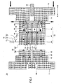
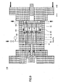
- FIG. 1 through FIG. 6 are cross-sectional views of an injection molding machine 10 according to a first embodiment of the present invention.
- FIG. 1 is a cross-sectional view of the injection molding machine 10 in a mold closing process.
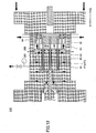
- FIG. 2 is a cross-sectional view of the injection molding machine 10 in a gas feeding process after a mold clamping process.
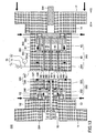
- FIG. 3 is a cross-sectional view of the injection molding machine 10 in an injection process.
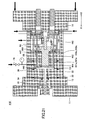
- FIG. 4 is a cross-sectional view of the injection molding machine 10 in a gas releasing process.
- FIG. 5 is a cross-sectional view of the injection molding machine 10 in a mold opening process.
- FIG. 6 is a cross-sectional view of the injection molding machine 10 in a molded article ejecting process.
- FIG. 7 is an enlarged view of part of the cross-sectional view of FIG. 2 .
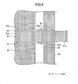
- FIG. 8 is an enlarged view of part of the cross-sectional view of FIG. 4 .
- the injection molding machine 10 includes a molding apparatus 20, an injection apparatus 50, an ejector apparatus 60, a gas feeding and discharging mechanism 70, and a gas releasing mechanism 80.
- the injection apparatus 50 injects a foamable resin into a cavity C1 ( FIG. 2 ) inside the molding apparatus 20 in a mold clamped state.
- the gas feeding and discharging mechanism 70 pre-feeds the cavity C1 with gas so that the pressure inside the cavity C1 increases to be higher than an atmospheric pressure.
- the gas feeding and discharging mechanism 70 and the gas releasing mechanism 80 release the gas inside the cavity C1 to the atmosphere through a pressure difference.
- the foamable resin is foamed so that a molded article M1 ( FIG. 5 ) is obtained that is substantially free of foaming marks on the surface and is foamed inside.
- the ejector apparatus 60 pushes the molded article M1 out of (ejects the molded article M1 from) the molding apparatus 20 in a mold open state.
- the molding apparatus 20 includes a stationary mold 30 as a first mold and a movable mold 40 as a second mold.
- the stationary mold 30 is fixed to a stationary platen 11 via a stationary adapter plate 13.
- the movable mold 40 is attached to a movable platen 12 via a movable adapter plate 14.
- a toggle mechanism (not graphically illustrated) is attached to the movable platen 12.
- the stationary platen 11, the movable platen 12, the stationary adapter plate 13, the movable adapter plate 14, and the toggle mechanism may form a mold clamping apparatus.
- the forward rotation of a drive motor (not graphically illustrated) of the mold clamping apparatus causes the movable platen 12 to move forward in a direction indicated by arrow X1, so that the movable mold 40 approaches the stationary mold 30 to close the molding apparatus 20.
- the rpm of the drive motor is controlled.
- torque control is performed on the forward rotation of the drive motor, so that the molding apparatus 20 is clamped as illustrated in FIG. 2 .
- the cavity C1 is formed between the stationary mold 30 and the movable mold 40.
- the movable platen 12 is caused to move backward in a direction indicated by arrow X2 as illustrated in FIG.
- the mold clamping apparatus may have a common configuration.
- the drive motor may be replaced with a hydraulic cylinder.
- a ball screw mechanism may be omitted that converts the rotational motion of the drive motor into a linear motion and transmits the linear motion to the movable platen 12.
- the stationary mold 30 includes a stationary mold plate 32 supported by the stationary adapter plate 13.
- a sprue bushing 33 that penetrates through the stationary mold plate 32 and the stationary adapter plate 13 includes a sprue S1 as a feed channel for feeding a foamable resin.
- the sprue bushing 33 is so fixed to the stationary adapter plate 13 with bolts or the like as to be replaceable when the sprue bushing 33 is degraded.
- Seal members 34 and 36 are attached to, for example, the stationary mold 30.
- a seal member 35 is attached to, for example, the stationary adapter plate 13.
- the seal members 34 through 36 are so arranged as to surround the sprue bushing 33.
- the seal members 34 through 36 are annularly formed. Examples of the seal members 34 through 36 include an O-ring.
- the seal member 34 seals the gap formed between the stationary mold plate 32 and the stationary adapter plate 13.
- the seal member 35 seals the gap formed between the stationary adapter plate 13 and the sprue bushing 33.
- the seal member 36 seals the gap formed between the stationary mold plate 32 and the movable mold plate 44 at the time of clamping the molding apparatus 20.
- the movable mold 40 includes, as a unit, a spacer block 42, a support plate 43, and a movable mold plate 44, which are arranged in this order from the movable adapter plate 14 side.
- the movable mold plate 44 and the stationary mold plate 32 are caused to come into contact and are clamped, so that the cavity C1 is formed.
- a recess (depressed part) 45 to form the cavity C1 and a groove part 46 are adjacently formed on the parting surface of the movable mold plate 44, which is a surface to come into contact with the stationary mold plate 32.
- the groove part 46 is shallower (smaller in depth) than the recess 45 in order to prevent a foamable resin from entering the groove part 46.
- a room (space) R1 surrounded by the spacer block 42 is formed between the movable adapter plate 14 and the support plate 43.
- the room R1 is formed for the below-described operations of the ejector apparatus 60 and the gas releasing mechanism 80.
- One or more ejector pin holes 47 into which one or more ejector pins 61 are movably inserted, are formed through the movable mold plate 44 and the support plate 43.
- the inside diameter of the ejector pin holes 47 is slightly larger than the outside diameter of the ejector pins 61.
- a seal member 48 ( FIG. 2 ) is attached to the movable mold 40.
- the seal member 48 seals the gap formed between the movable mold plate 44 and the support plate 43.
- the seal member 48 is annularly formed and is so disposed as to surround the ejector pin holes 47.
- the injection apparatus 50 is pressed against the sprue bushing 33 to inject a given amount of foamable resin into the cavity C1 via the sprue S1.
- the foamable resin is, for example, a mixture of a heated, molten resin and a blowing gas as a foaming agent.
- the blowing gas is in its critical state when mixed with the resin.
- the blowing gas is not limited in particular, and may be, for example, carbon dioxide, nitrogen, air, or the like.
- the injection apparatus 50 may contain a needle valve mechanism configured to open and close a nozzle hole for injecting a foamable resin.
- the ejector apparatus 60 pushes out the molded article M1, molded inside the cavity C1, from the movable mold plate 44 after the molding apparatus 20 is opened.
- the ejector apparatus 60 includes the ejector pins 61, an ejector plate 62, and an ejector rod 63.
- the ejector pins 61 are movable relative to the movable mold plate 44.
- the ejector pins 61 and the ejector plate 62 are movable as a unit.
- the ejector rod 63 pushes the ejector plate 62 from its rear side.
- the ejector plate 62 is disposed inside the room R1, and is so supported by below-described hydro pneumatic cylinders 84 (specifically, cylinder bodies 84a) as to be movable in the directions indicated by arrows X1 and X2.
- the ejector plate 62 is urged in the backward direction (the direction indicated by arrow X2) by an urging member such as a spring.
- the gas feeding and discharging mechanism 70 includes a gas feeding and discharging pipe 71 for feeding gas to and discharging gas from the cavity C1.
- the gas feeding and discharging pipe 71 is connected via the groove part 46 to the recess 45, which forms the cavity C1.
- An on-off valve 72 and a gas manometer 73 are provided in the gas feeding and discharging pipe 71.
- the gas feeding and discharging mechanism 70 feeds the cavity C1 with gas so that the pressure inside the cavity C1 increases to be higher than an atmospheric pressure before the injection apparatus 50 injects a foamable resin after the molding apparatus 20 is clamped.
- the pressure inside the cavity C1 is substantially the same as the pressure of the blowing gas in the injection apparatus 50, for example, 3 MPa to 14.5 MPa.
- the gas releasing mechanism 80 releases the gas inside the cavity C1 to the atmosphere using a pressure difference during or after the injection of the foamable resin by the injection apparatus 50.
- the foamable resin is foamed, so that the molded article M1 ( FIG. 5 ) is obtained that is substantially free of foaming marks on the surface and is foamed inside.
- the gas feeding and discharging mechanism 70 may also release the gas inside the cavity C1 to the atmosphere using a pressure difference in combination with the gas releasing mechanism 80. This increases the degassing (gas releasing) rate, so that generation of minute irregularities due to residual gas is prevented and the molded article M1 is obtained with good quality of appearance.
- the gas releasing mechanism 80 releases the gas inside the cavity C1 to the atmosphere using a pressure difference through a gap G1 formed between an inner wall surface 47a of each ejector pin hole 47 and an outer circumferential (peripheral) surface 61a of the corresponding ejector pin 61.
- the gas inside the cavity C1 passes through the gap G1 to be released to the room R1, and is thereafter released to the atmosphere through a gap formed between the support plate 43 and the spacer block 42 surrounding the room R1.
- the existing gaps G1 which have been formed for another purpose, are used as a gas releasing channel. Therefore, it is possible to simplify the configuration of the molding apparatus 20. This makes it easy to design the molding apparatus 20, so that it is possible to reduce the cost of the molding apparatus 20. Further, it is possible to reduce the molding apparatus 20 in size.
- the end faces 61b ( FIG. 1 ) of the ejector pins 61 forming a gas releasing channel form part of a wall surface of the cavity C1. This allows the gas inside the cavity C1 to be swiftly released to the atmosphere.
- the gas releasing mechanism 80 includes an opening and closing mechanism configured to open and close a gas releasing channel including the gaps G1 ( FIG. 7 and FIG. 8 ). As illustrated in FIG. 4 , this opening and closing mechanism includes first ferrules 81, second ferrules 82, a seal plate 83, and the hydro pneumatic cylinders 84.
- the first ferrules 81 and the second ferrules 82 are annular, and have respective holes for inserting the corresponding ejector pins 61 formed in their respective center portions.
- the inside diameter of the first ferrules 81 and the second ferrules 82 is slightly larger than the outside diameter of the ejector pins 61.
- the first ferrules 81 are provided one for each of the ejector pins 61.
- the second ferrules 82 are provided one for each of the ejector pins 61.
- the seal plate 83 is so disposed inside the room R1 as to be movable in the directions indicated by arrows X1 and X2. Insertion holes 83a ( FIG. 7 ) into which the ejector pins 61 are movably inserted are formed through the seal plate 83.
- the hydro pneumatic cylinders 84 are hydraulic cylinders or pneumatic cylinders. Referring to FIG. 2 , each of the hydro pneumatic cylinders 84 includes the cylinder body 84a and a rod 84b projecting from the cylinder 84. As illustrated in FIG. 4 , the hydro pneumatic cylinders 84 are connected to the movable adapter plate 14 at their respective rear end portions (for example, cylinder bodies 84a), and are connected to the seal plate 83 at their respective front end portions (for example, rods 84b).
- the seal plate 83 and the first and second ferrules 81 and 82 are caused to move forward and backward in the directions indicated by arrows X1 and X2 to move toward and away from the support plate 43.
- the extension of the hydro pneumatic cylinders 84 causes the first and second ferrules 81 and 82 to be held between the seal plate 83 and the support plate 43 and axially compressed.
- an exterior surface 81a of the first ferrule 81 is pressed against the inner wall surface 47a of the corresponding ejector pin holes 47.
- the first ferrule 81 compresses the second ferrule 82 radially inward.
- an inner circumferential surface 82a of the second ferrule 82 is pressed against the outer circumferential surface 61a of the ejector pin 61, so that the gas releasing channel including the gaps G1 is closed.
- the retraction of the hydro pneumatic cylinders 84 causes the seal plate 83 to move backward, so that the pressures on the first and second ferrules 81 and 82 in their axial directions are removed.
- the second ferrule 82 is elastically restored to its original state, so that the inner circumferential surface 82a of the second ferrule 82 is separated from the outer circumferential surface 61a of the ejector pin 61.
- the exterior surface 81a of the first ferrule 81 is detached from (comes out of contact with) the inner wall surface 47a of the ejector pin hole 47 because of a difference in pressure between the gaps G1 and the room R1.
- the gas releasing channel including the gaps G1 is opened.
- the gas releasing mechanism 80 opens and closes the gas releasing channel including the gaps G1 in this manner.
- an operation (an injection molding method) of the injection molding machine 10 having the above-described configuration.
- the below-described operations are controlled by a controller (not graphically illustrated) implemented by a computer including a central processing unit (CPU), a recording medium, a timer, etc.
- the controller may be connected to or provided in the injection molding machine 10.
- the mold clamping apparatus causes the movable platen 12 to move forward in the direction indicated by arrow X1, so that the movable mold 40 approaches the stationary mold 30 to close the molding apparatus 20.
- a limit switch is turned ON, so that the timer (of the controller) starts counting (measuring) time.
- the gas releasing mechanism 80 closes the gas releasing channel including the gaps G1. This process is performed before the feeding of gas by the gas feeding and discharging mechanism 70. This process may be performed after the clamping of the molding apparatus 20.
- the movable mold plate 44 is pressed against the stationary mold plate 32, so that the molding apparatus 20 is clamped.
- the movable mold plate 44 and the stationary mold plate 32 are clamped so that the cavity C1 is formed.
- the gas feeding and discharging mechanism 70 fees gas into the cavity C1, so that the pressure inside the cavity C1 increases to be higher than an atmospheric pressure.
- Increasing the pressure inside the cavity C1 is started when the time counted (measured) by the timer reaches a predetermined set time T1.
- the gas releasing mechanism 80 closes the gas releasing channel including the gaps G1.
- the injection apparatus 50 injects a foamable resin into the cavity C1 through the sprue S1.
- the injection of the foamable resin is started when the time counted by the timer reaches a predetermined set time T2 (T2 > T1).
- T2 a predetermined set time
- the gas feeding and discharging mechanism 70 keeps the pressure inside the cavity C1 constant for a predetermined time after the start of the injection of the foamable resin.
- the gas releasing mechanism 80 opens the gas releasing channel including the gaps G1, and releases the gas inside the cavity C1 to the atmosphere using a pressure difference.
- the gas inside the cavity C1 is released to the room R1 through the gaps G1, and is thereafter released to the atmosphere through a gap formed between the support plate 43 and the spacer block 42 surrounding the room R1.
- the gas feeding and discharging mechanism 70 along with the gas releasing mechanism 80, releases the gas inside the cavity C1 to the atmosphere using a pressure difference.
- the release of gas is started when the time counted by the timer reaches a predetermined set time T3 (T3 > T2).
- the return of the pressure inside the cavity C1 to an atmospheric pressure causes the foamable resin to be foamed inside the cavity C1, so that the molded article M1 ( FIG. 5 ) is obtained that is substantially free of foaming marks on the surface and is foamed inside.
- the release of gas may also be started during the injection of the foamable resin.
- the mold clamping apparatus causes the movable platen 12 to move backward in the direction indicated by arrow X2, so that the movable mold 40 is separated from (comes out of contact with) the stationary mold 30 to open the molding apparatus 20.
- the foamable resin may also be foamed by substantially increasing the volume of the cavity C1 by opening the molding apparatus 20.
- the ejector apparatus 60 pushes the molded article M1 out of the movable mold plate 44.
- the ejector plate 62 is pushed from the rear side by the forward movement of the ejector rod 63 to move forward in the direction indicated by arrow X1 against the urging force of a spring.
- the ejector pins 61 are caused to move forward relative to the movable mold plate 44 to push the molded article M1 out of the movable mold plate 44.
- the molded article M1 is obtained.
- FIG. 9 and FIG. 10 are cross-sectional views of an injection molding machine 110 according to a first variation of the first embodiment of the present invention.
- FIG. 9 is a cross-sectional view of the injection molding machine 110 in a gas feeding process after a mold clamping process.
- FIG. 10 is a cross-sectional view of the injection molding machine 110 in a gas releasing process.
- the injection molding machine 110 according to this variation has the same configuration as the injection molding apparatus 10 of the above-described embodiment except for a gas releasing mechanism 180. Accordingly, a description of the configuration other than the gas releasing mechanism 180 is omitted.
- the gas releasing mechanism 180 of this variation includes a seal plate 181, seal members 182 and 183, and hydro pneumatic cylinders 184 as an opening and closing mechanism configured to open and close a gas releasing channel including the gaps G1 ( FIG. 7 and FIG. 8 ).
- the seal plate 181 is so disposed inside the room R1 as to be movable in the directions indicated by arrows X1 and X2. Insertion holes into which the ejector pins 61 are movably inserted are formed through the seal plate 181.
- the seal members 182 are annular, and are so fixed to the seal plate 181 as to surround the corresponding ejector pins 61.
- the seal members 182 seal the gaps formed between the seal plate 181 and the ejector pins 61.
- the seal members 182 are provided one for each of the ejector pins 61.
- the seal member 183 is annular, and is so fixed to the support plate 43 (or the seal plate 181) as to surround the ejector pins 61.
- the support plate 43 and the seal plate 181 come into and out of contact with each other through the seal member 183, so that the gas releasing channel including the gaps G1 is closed and opened.
- the hydro pneumatic cylinders 184 are connected to the movable adapter plate 14 at their respective rear end portions, and are connected to the seal plate 181 at their respective front end portions. The extension and retraction of the hydro pneumatic cylinders 184 cause the seal plate 181 to move forward and backward.
- the extension of the hydro pneumatic cylinders 184 causes the seal plate 181 to move forward in the direction indicated by arrow X1 to come into contact with the support plate 43 through the seal member 183. As a result, the gas releasing channel including the gaps G1 is closed.
- the retraction of the hydro pneumatic cylinders 184 causes the seal plate 181 to move backward in the direction indicated by arrow X2 to be separated from the seal member 183. As a result, the gas releasing channel including the gaps G1 is opened.
- the gas releasing mechanism 180 opens and closes the gas releasing channel including the gaps G1 in this manner.
- FIG. 11 and FIG. 12 are cross-sectional views of an injection molding machine 210 according to a second variation of the first embodiment of the present invention.
- FIG. 11 is a cross-sectional view of the injection molding machine 210 in a gas feeding process after a mold clamping process.
- FIG. 12 is a cross-sectional view of the injection molding machine 210 in a gas releasing process.
- the injection molding machine 210 according to this variation has the same configuration as the injection molding apparatus 10 of the above-described embodiment except for a gas releasing mechanism 280. Accordingly, a description of the configuration other than the gas releasing mechanism 280 is omitted.
- the gas releasing mechanism 280 of this variation includes the first and second ferrules 81 and 82, the seal plate 83, the hydro pneumatic cylinders 84, and a seal member 281 as an opening and closing mechanism configured to open and close a gas releasing channel including the gaps G1 ( FIG. 7 and FIG. 8 ).
- the seal member 281 is annular, and is so fixed to the support plate 43 (or the seal plate 83) as to surround the ejector pins 61.
- the support plate 43 and the seal plate 83 come into and out of contact with each other through the seal member 281, so that the gas releasing channel including the gaps G1 is closed and opened.
- the gas releasing mechanism 280 of this variation includes the seal member 281. Accordingly, it is still possible to disconnect the cavity C1 from the atmosphere even when the first ferrules 81 are degraded.
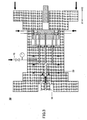
- FIG. 13 through FIG. 18 are cross-sectional views of an injection molding machine 310 according to a second embodiment of the present invention.
- FIG. 13 is a cross-sectional view of the injection molding machine 310 in a mold closing process.
- FIG. 14 is a cross-sectional view of the injection molding machine 310 in a gas feeding process after a mold clamping process.
- FIG. 15 is a cross-sectional view of the injection molding machine 310 in an injection process.
- FIG. 16 is a cross-sectional view of the injection molding machine 310 in a gas releasing process.
- FIG. 17 is a cross-sectional view of the injection molding machine 310 in a mold opening process.
- FIG. 18 is a cross-sectional view of the injection molding machine 310 in a molded article ejecting process.
- FIG. 19 is an enlarged view of part of the cross-sectional view of FIG. 14 .
- the injection molding machine 310 includes a molding apparatus 320, the injection apparatus 50, an ejector apparatus 360, and the gas feeding and discharging mechanism 70.
- the injection molding machine 310 further includes a first gas releasing mechanism 380 and a second gas releasing mechanism 390.
- the injection molding machine 310 further includes gas releasing channels for releasing gas inside cavities C2 ( FIG. 14 ) one on each of the stationary mold 330 side and the movable mold 340 side.
- the molding apparatus 320 includes a stationary mold 330 as a first mold and a movable mold 340 as a second mold.
- the stationary mold 330 is fixed to the stationary platen 11 via the stationary adapter plate 13.
- the movable mold 340 is attached to the movable platen 12 via the movable adapter plate 14.
- the movable plate 12 moves forward in the direction indicated by arrow X1 and backward in the direction indicated by arrow X2, so that the molding apparatus 320 is closed ( FIG. 13 ), clamped ( FIG. 14 ), and opened ( FIG. 17 ).
- the multiple cavities C2 ( FIG. 14 ) are formed between the stationary mold 330 and the movable mold 340 at the time of clamping the molding apparatus 320.
- the cavities C2 communicate with a sprue S2 via a runner RU ( FIG. 14 ).
- the stationary mold 330 includes, as a unit, a stationary spacer block 332 and a stationary mold plate 333, which are arranged in this order from the stationary adapter plate 13 side.
- a room (space) R2 surrounded by the stationary spacer block 332 is formed between the stationary adapter plate 13 and the stationary mold plate 333.
- the room R2 is formed for the below-described operation of a second gas releasing mechanism 390.
- a sprue bushing 334 that penetrates through the stationary adapter plate 13 and the stationary mold plate 333 includes the sprue S2 as a feed channel for feeding a foamable resin.
- the sprue bushing 334 is so fixed to the stationary adapter plate 13 with bolts or the like as to be replaceable when the sprue bushing 334 is degraded.
- a seal member 335 ( FIG. 14 ) that seals the gap formed between the sprue bushing 334 and the stationary mold plate 333 is attached to the stationary mold 330.
- the seal member 335 is annular and is so disposed as to surround the sprue bushing 334.
- a seal member 336 ( FIG. 14 ) that seals the gap formed between the stationary mold plate 333 and a movable mold plate 344 at the time of clamping the molding apparatus 320 is attached to the stationary mold 330.
- the seal member 336 is annular and is so disposed as to surround below-described multiple cavity pin holes 337.
- the stationary mold 330 includes multiple cavity pins 338 serving as cores that form part of respective wall surfaces of the cavities C2.
- the cavity pins 338 are provided one for each of the cavities C2.
- the cavity pins 338 are inserted into the corresponding cavity pin holes 337 formed through the stationary mold plate 333.
- the inside diameter of the cavity pin holes 337 is slightly larger than the outside diameter of the cavity pins 338.
- the cavity pin holes 337 are formed one for each of the cavity pins 338.
- the cavity pins 338 are so fixed to the stationary mold plate 333 with bolts or the like as to be replaceable when the cavity pins 338 are degraded.
- the movable mold 340 includes, as a unit, the spacer block 42, the support plate 43, and the movable mold plate 344, which are arranged in this order from the movable adapter plate 14 side.
- the movable mold plate 344 and the stationary mold plate 333 are caused to come into contact with each other and are clamped, so that the multiple cavities C2 are formed.
- the cavities C2 communicate with the sprue S2 via the runner RU.
- Multiple recesses (depressed parts) 345 to form part of the cavities C2, a groove part 346 adjacent to one of the recesses 345, and a recess 347 defining the runner RU are formed on the parting surface of the movable mold plate 344, which is a surface to come into contact with the stationary mold plate 333.
- the groove part 346 is shallower (less in depth) than the recess 345 in order to prevent a foamable resin from entering the groove part 346.
- the multiple recesses 345 are connected by the recess 347.
- Ejector pin holes 348 and 349 into which ejector pins 361 and 362 are movably inserted, respectively, are formed through the movable mold plate 344 and the support plate 43.
- the inside diameter of the ejector pin holes 348 and 349 is slightly larger than the outside diameter of the ejector pins 361 and 362.
- a seal member SE ( FIG. 14 ) that seals the gap formed between the movable mold plate 344 and the support plate 43 is attached to the movable mold 340.
- the seal member SE is annular and is so disposed as to surround the ejector pin holes 348 and 349.
- the ejector apparatus 360 pushes out multiple molded articles M2, molded inside the multiple cavities C2, and the resin solidified in the runner RU from the movable mold plate 344 after the molding apparatus 320 is opened.
- the ejector apparatus 360 includes the ejector pins 361 and 362, an ejector plate 363, and an ejector rod 364.
- the ejector pins 361 and 362 are movable relative to the movable mold plate 344.
- the ejector pins 361 and 362 and the ejector plate 363 are movable as a unit.
- the ejector rod 3634 pushes the ejector plate 363 from its rear side.
- the ejector plate 363 is disposed inside the room R1, and is so supported by the hydro pneumatic cylinders 84 as to be movable in the directions indicated by arrows X1 and X2.
- the ejector plate 363 is urged in the backward direction (the direction indicated by arrow X2) by an urging member such as a spring.
- the ejector plate 363 As illustrated in FIG. 18 , as the ejector rod 364 moves forward, the ejector plate 363 is pushed from the rear side to move forward in the direction indicated by arrow X1 against the urging force of the spring. As a result, the ejector pins 361 are caused to move forward relative to the movable mold plate 344 to push the molded articles M2, molded inside the cavities C2, out of the movable mold plate 344. Likewise, the ejector pin 362 pushes the resin solidified in the runner RU out of the movable mold plate 344.
- respective end faces 361b ( FIG. 19 ) of the ejector pins 361 are substantially in the same plane as inside bottom surfaces 345a ( FIG. 19 ) of the recesses 345 to form part of wall surfaces of the cavities C2 at the time of mold clamping.
- an end face 362b ( FIG. 19 ) of the ejector pin 362 is substantially in the same plane as an inside bottom surface 347a ( FIG. 19 ) of the recess 347 to form part of a wall surface of the runner RU at the time of mold clamping.
- the first gas releasing mechanism 380 and the second gas releasing mechanism 390 release the gas inside the cavities C2 to the atmosphere using a pressure difference during or after the injection of the foamable resin by the injection apparatus 50.
- the foamable resin is foamed, so that the molded articles M2 ( FIG. 18 ) are obtained that are substantially free of foaming marks on their surfaces and are foamed inside.
- the gas feeding and discharging mechanism 70 may also release the gas inside the cavities C2 to the atmosphere using a pressure difference in combination with the first and second gas releasing mechanisms 380 and 390. This increases the degassing (gas releasing) rate, so that generation of minute irregularities due to residual gas is prevented and the molded articles M2 are obtained with good quality of appearance.
- the first gas releasing mechanism 380 releases the gas inside the cavities C2 to the atmosphere using a pressure difference through gaps G2 and a gap G3 ( FIG. 19 ).
- the gaps G2 are formed one between an inner wall surface 348a of each ejector pin hole 348 and an outer circumferential (peripheral) surface 361a of the corresponding ejector pin 361.
- the gap G3 is formed between an inner wall surface 349a of the ejector pin hole 349 and an outer circumferential (peripheral) surface 362a of the corresponding ejector pin 362.
- the gas inside the cavities C2 passes through the gaps G2 and G3 to be released to the room R1, and is thereafter released to the atmosphere through a gap formed between the support plate 43 and the spacer block 42 surrounding the room R1.
- the existing gaps G2 and G3, which have been formed for other purposes, are used as a gas releasing channel. Therefore, it is possible to simplify the configuration of the molding apparatus 320. This makes it easy to design the molding apparatus 320, so that it is possible to reduce the cost of the molding apparatus 320. Further, it is possible to reduce the molding apparatus 320 in size.
- the end faces 361b of the ejector pins 361 forming a gas releasing channel form part of wall surfaces of the cavities C2. This allows the gas inside the cavities C2 to be swiftly released to the atmosphere.
- the first gas releasing mechanism 380 includes an opening and closing mechanism configured to open and close a gas releasing channel including the gaps G2 and G3 ( FIG. 19 ). As illustrated in FIG. 16 , this opening and closing mechanism includes the first ferrules 81, the second ferrules 82, the seal plate 83, and the hydro pneumatic cylinders 84.
- the first ferrules 81 and the second ferrules 82 are annular, and have respective holes for inserting the corresponding ejector pins 361 and 362 formed in their respective center portions.
- the inside diameter of the first ferrules 81 and the second ferrules 82 is slightly larger than the outside diameter of the ejector pins 361 and 362.
- the first ferrules 81 are provided one for each of the ejector pins 361 and 362.
- the second ferrules 82 are provided one for each of the ejector pins 361 and 362.
- the seal plate 83 is so disposed inside the room R1 as to be movable in the directions indicated by arrows X1 and X2.
- the insertion holes 83a FIG. 7 ) into which the ejector pins 361 and 362 are movably inserted are formed through the seal plate 83.
- the seal plate 83 and the first and second ferrules 81 and 82 are caused to move forward and backward in the directions indicated by arrows X1 and X2 to move toward and away from the support plate 43. Accordingly, like in the first embodiment, the gas releasing channel including the gaps G2 and G3 is opened and closed.
- the second gas releasing mechanism 390 releases the gas inside the cavities C2 to the atmosphere using a pressure difference through gaps G4 ( FIG. 19 ).
- the gaps G4 are formed between inner wall surfaces 337a of the cavity pin holes 337 and outer circumferential (peripheral) surfaces 338a of the corresponding cavity pins 338.
- the gas inside the cavities C2 passes through the gaps G4 to be released to the room R2, and is thereafter released to the atmosphere through a gap formed between the stationary mold plate 333 and the stationary spacer block 332 surrounding the room R2.
- the gas releasing channels are provided one on each of the movable mold 340 side and the stationary mold 330 side. This increases the degassing (gas releasing) rate.
- rear end faces 338b ( FIG. 19 ) of the cavity pins 338 forming a gas releasing channel form part of wall surfaces of the cavities C2. This allows the gas inside the cavities C2 to be swiftly released to the atmosphere.
- the second gas releasing mechanism 390 includes an opening and closing mechanism configured to open and close a gas releasing channel including the gaps G4 ( FIG. 19 ). As illustrated in FIG. 16 , this opening and closing mechanism includes a seal plate 391, seal members 392 and 393, and hydro pneumatic cylinders 394.
- the seal plate 391 is so disposed inside the room R2 as to be movable in the directions indicated by arrows X1 and X2.
- An insertion hole 391a into which the sprue bushing 334 is movably inserted is formed through the seal plate 391.
- the seal member 392 is annular.
- the seal member 392 is so disposed as to surround the sprue bushing 334 and to be positioned inside the cavity pins 338 (in a plan view in the direction indicated by arrow X2).
- the seal member 393 is annular and is so disposed as to surround the cavity pins 338 (in a plan view in the direction indicated by arrow X2).
- the seal members 392 and 393 are fixed to the seal plate 391 (or the stationary mold plate 333).
- the seal plate 391 and the stationary mold plate 333 come into and out of contact with each other through the seal members 392 and 393, so that the gas releasing channel including the gaps G4 is closed and opened.
- the hydro pneumatic cylinders 394 are connected to the stationary adapter plate 13 at their respective front end portions, and are connected to the seal plate 391 at their respective rear end portions. The extension and retraction of the hydro pneumatic cylinders 394 cause the seal plate 391 to move backward and forward.
- the extension of the hydro pneumatic cylinders 394 causes the seal plate 391 to move backward in the direction indicated by arrow X2 to come into contact with the stationary mold plate 333 through the seal members 392 and 393. As a result, the gas releasing channel including the gaps G4 is closed.
- the retraction of the hydro pneumatic cylinders 394 causes the seal plate 391 to move forward in the direction indicated by arrow X1 so that the seal members 392 and 393 are separated from the stationary mold plate 333. As a result, the gas releasing channel including the gaps G4 is opened.
- the operation (the injection molding method) of the injection molding machine 310 of this embodiment is the same as that of the injection molding machine 10 of the first embodiment, and accordingly, a description thereof is omitted.
- the injection molding machine 310 includes the first and second gas releasing mechanisms 380 and 390. However, the injection molding machine 310 may also be configured to include one of the first and second gas releasing mechanisms 380 and 390.
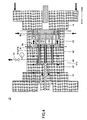
- FIG. 20 through FIG. 25 are cross-sectional views of an injection molding machine 410 according to a third embodiment of the present invention.
- FIG. 20 is a cross-sectional view of the injection molding machine 410 in a mold closing process.
- FIG. 21 is a cross-sectional view of the injection molding machine 410 in a gas feeding process after a mold clamping process.
- FIG. 22 is a cross-sectional view of the injection molding machine 410 in an injection process.
- FIG. 23 is a cross-sectional view of the injection molding machine 410 in a gas releasing process.
- FIG. 24 is a cross-sectional view of the injection molding machine 410 in a mold opening process.
- FIG. 25 is a cross-sectional view of the injection molding machine 410 in a molded article ejecting process.
- FIG. 26 is an enlarged view of part of the cross-sectional view of FIG. 21 .
- the injection molding machine 410 includes a molding apparatus 420, the injection apparatus 50, ejector apparatuses 460, the gas feeding and discharging mechanism 70, and a gas releasing mechanism 480.
- the gas releasing mechanism 480 of this embodiment is configured to change the volume of a cavity C3 ( FIG. 21 ) inside the molding apparatus 420.
- the molding apparatus 420 includes the stationary mold 30 as a first mold and a movable mold 440 as a second mold.
- the stationary mold 30 is fixed to the stationary platen 11 via the stationary adapter plate 13.
- the movable mold 440 is attached to the movable platen 12 via the movable adapter plate 14.
- the movable plate 12 moves forward in the direction indicated by arrow X1 and backward in the direction indicated by arrow X2, so that the molding apparatus 420 is closed ( FIG. 20 ), clamped ( FIG. 21 ), and opened ( FIG. 24 ).
- the movable mold 440 includes, as a unit, a spacer block 442, a support plate 443, and a movable mold plate 444, which are arranged in this order from the movable adapter plate 14 side.
- the movable mold plate 444 and the stationary mold plate 32 are caused to come into contact and are clamped, so that the cavity C3 is formed.
- a recess (depressed part) 445 to form part of the cavity C3 and a groove part 446 are adjacently formed on the parting surface of the movable mold plate 444, which is a surface to come into contact with the stationary mold plate 32.
- the groove part 446 is shallower (less in depth) than the recess 445 in order to prevent a foamable resin from entering the groove part 446.
- a room (space) R3 surrounded by the spacer block 442 is formed between the movable adapter plate 14 and the support plate 443.
- the room R3 is formed for the below-described operations of the ejector apparatuses 460 and the gas releasing mechanism 480.
- One or more ejector pin holes 447 into which one or more ejector pins 461 are movably inserted, are formed through the movable mold plate 444 and the support plate 443.
- the inside diameter of the ejector pin holes 447 is slightly larger than the outside diameter of the ejector pins 461.
- the movable mold 440 includes a slide core 448 that changes the volume of the cavity C3.
- the slide core 448 includes a body part 448a ( FIG. 22 ) and a head part 448b ( FIG. 22 ) as a unit.
- the body part 448a is movably inserted into a guide hole 449 formed through the movable mold plate 444 and the support plate 443.
- the head part 448b is larger in size than the guide hole 449.
- the head part 448b is disposed outside the guide hole 449, for example, in the room R3.
- the seal member SE ( FIG. 21 ) that seals the gap formed between the movable mold plate 444 and the support plate 443 is attached to the movable mold 440.
- the seal member SE is annular and is so disposed as to surround the ejector pin holes 447 and the guide hole 449.
- the ejector apparatuses 460 push out a molded article M3, molded inside the cavity C3, from the movable mold plate 444 after the molding apparatus 420 is opened.
- the ejector apparatuses 460 are provided one for each of the ejector pin holes 447.
- Each of the ejector apparatuses 460 includes the ejector pin 461, an ejector plate 462, and an ejector rod 463.
- the ejector pin 461 is movable relative to the movable mold plate 444.
- the ejector pin 461 and the ejector plate 462 are movable as a unit.
- the ejector rod 463 pushes the ejector plate 462 from its rear side.
- the ejector plates 462 are disposed inside the room R3, and are so supported by the corresponding hydro pneumatic cylinders 84 as to be movable in the directions indicated by arrows X1 and X2.
- the ejector plates 462 are urged in the backward direction (the direction indicated by arrow X2) by respective urging members such as springs.
- the gas releasing mechanism 480 releases the gas inside the cavity C3 to the atmosphere during or after the injection of the foamable resin by the injection apparatus 50. At this point, the foamable resin is foamed, so that the molded article M3 ( FIG. 24 ) is obtained that is substantially free of foaming marks on the surface and is foamed inside.
- the gas feeding and discharging mechanism 70 may also release the gas inside the cavity C3 to the atmosphere using a pressure difference in combination with the gas releasing mechanism 480. This increases the degassing (gas releasing) rate, so that generation of minute irregularities due to residual gas is prevented and the molded article M3 is obtained with good quality of appearance.
- the gas releasing mechanism 480 releases the gas inside the cavity C3 to the atmosphere using a pressure difference through gaps G5 and a gap G6 ( FIG. 26 ).
- the gaps G5 are formed between inner wall surfaces 447a of the ejector pin holes 447 and outer circumferential (peripheral) surfaces 461a of the corresponding ejector pins 461.
- the gap G6 is formed between an inner wall surface 449a of the guide hole 449 and an outer circumferential (peripheral) surface 448c of the body part 448a of the slide core 448.
- the gas inside the cavity C3 passes through the gaps G5 and G6 to be released to the room R3, and is thereafter released to the atmosphere through a gap formed between the support plate 443 and the spacer block 442 surrounding the room R3.
- the existing gaps G5 and G6, which have been formed for other purposes, are used as a gas releasing channel. Therefore, it is possible to simplify the configuration of the molding apparatus 420. This makes it easy to design the molding apparatus 420, so that it is possible to reduce the cost of the molding apparatus 420. Further, it is possible to reduce the molding apparatus 420 in size.
- the end faces 461b of the ejector pins 461 forming a gas releasing channel form part of a wall surface of the cavity C3. This allows the gas inside the cavity C3 to be swiftly released to the atmosphere.
- the body part 448a of the slide core 448 forming a gas releasing channel forms part of a wall surface of the cavity C3. This allows the gas inside the cavity C3 to be swiftly released to the atmosphere.
- the gas releasing mechanism 480 includes an opening and closing mechanism configured to open and close a gas releasing channel including the gaps G5 ( FIG. 26 ). As illustrated in FIG. 23 , the opening and closing mechanism includes the first and second ferrules 81 and 82, a seal plate 483, and the hydro pneumatic cylinders 84.
- the first and second ferrules 81 and 82 are annular, and have respective holes for inserting the corresponding ejector pins 461 formed in their respective center portions.
- the inside diameter of the first and second ferrules 81 and 82 is slightly larger than the outside diameter of the ejector pins 461.
- the first ferrules 81 are provided one for each of the ejector pins 461.
- the second ferrules 82 are provided one for each of the ejector pins 461.
- Insertion holes into which the ejector pins 461 are movably inserted and an insertion hole into which the head part 448b ( FIG. 22 ) of the slide core 448 is inserted are formed through the seal plate 483.
- the seal plate 483 and the first and second ferrules 81 and 82 are caused to move forward and backward in the directions indicated by arrows X1 and X2 to move toward and away from the support plate 443. Accordingly, like in the first embodiment, the gas releasing channel including the gaps G5 is opened and closed.
- the gas releasing mechanism 480 includes an opening and closing mechanism configured to open and close a gas releasing channel including the gap G6 ( FIG. 26 ). As illustrated in FIG. 23 , this opening and closing mechanism includes a seal member 486 and a hydro pneumatic cylinder 487.
- the seal member 486 is annular.
- the seal member 486 is so disposed as to surround the body part 448a of the slide core 448, and is fixed to the head part 448b (or the support plate 443).
- the support plate 443 and the head part 448b come into and out of contact with each other through the seal member 486, so that the gas releasing channel including the gap G6 is closed and opened.
- the hydro pneumatic cylinder 487 is connected to the movable adapter plate 14 at its rear end portion, and is connected to the head part 448b at its front end portion. The extension and retraction of the hydro pneumatic cylinder 487 cause the head part 448b to move forward and backward.
- the extension of the hydro pneumatic cylinder 487 causes the head part 448b to move forward in the direction indicated by arrow X1 to come into contact with the support plate 443 through the seal member 486. As a result, the gas releasing channel including the gap G6 is closed.
- the retraction of the hydro pneumatic cylinder 487 causes the head part 448b to move backward in the direction indicated by arrow X2 so that the seal member 486 is separated from the support plate 443. As a result, the gas releasing channel including the gap G6 is opened.
- the volume of the cavity C3 increases to cause the foamable resin to expand. Therefore, it is possible to further reduce the weight of the molded article M3.
- the operation (the injection molding method) of the injection molding machine 410 of this embodiment is the same as that of the injection molding machine 10 of the first embodiment, and accordingly, a description thereof is omitted.
- the above-described gas feeding and discharging mechanism 70 is configured to feed gas to and discharge gas from the cavities C1 through C3.
- the gas feeding and discharging mechanism 70 may also be configured to have the function of feeding gas to the cavities C1 through C3 without the function of discharging gas from the cavities C1 through C3.
- the above-described movable molds 40, 340, and 440 include the support plate 43 or 443 that reinforces the movable mold plate 44, 344, or 444.
- the support plate 43 or 443 may be omitted. If the support plate 43 or 443 is omitted, the gas releasing mechanisms 80, 180, 280, 380 and 480 may open and close a gas releasing channel by causing the seal plate 83, 181 or 483 to move toward and away from the movable mold plate 44, 344 or 444 instead of the support plate 43 or 443.
- the driving source that causes the seal plates 83, 181, 391 and 483 to move is not limited to a hydro pneumatic cylinder as described above, and may be, for example, a ball screw mechanism.
Abstract
Description
- The present application is based upon and claims the benefit of priority of Japanese Patent Application No.
2011-096415, filed on April 22, 2011 - The present invention relates to an injection molding machine and an injection molding method.
- Gas counter pressure (GCP) molding is widely used as an injection molding method. (See, for example, Japanese Laid-Open Patent Application No.
61-239916 - According to an aspect of the present invention, an injection molding machine includes a gas feeding mechanism configured to feed gas to a cavity formed between a first mold plate and a second mold plate in a clamped state; an injection apparatus configured to inject a foamable resin into the cavity having an inside pressure thereof increased to be higher than an atmospheric pressure by the gas feeding mechanism; and a gas releasing mechanism configured to release the gas inside the cavity to an atmosphere through a gap formed between an inner wall surface of a through hole formed through one of the first mold plate and the second mold plate and an outer circumferential surface of a mold member inserted into the through hole, during or after the injection of the foamable resin by the injection apparatus.
- According to an aspect of the present invention, an injection molding method includes clamping a first mold plate and a second mold plate to form a cavity between the first mold plate and the second mold plate; feeding gas to the cavity so that a pressure inside the cavity increases to be higher than an atmospheric pressure; injecting a foamable resin into the cavity after feeding the gas; and releasing the gas inside the cavity to an atmosphere through a gap formed between an inner wall surface of a through hole formed through one of the first mold plate and the second mold plate and an outer circumferential surface of a mold member inserted into the through hole, during or after injecting the foamable resin.
- The object and advantages of the embodiments will be realized and attained by means of the elements and combinations particularly pointed out in the claims.
- It is to be understood that both the foregoing general description and the following detailed description are exemplary and explanatory and not restrictive of the invention as claimed.
- Other objects, features and advantages of the present invention will become more apparent from the following detailed description when read in conjunction with the accompanying drawings, in which:
-
FIG. 1 is a cross-sectional view of an injection molding machine according to a first embodiment of the present invention; -
FIG. 2 is another cross-sectional view of the injection molding machine according to the first embodiment of the present invention; -
FIG. 3 is another cross-sectional view of the injection molding machine according to the first embodiment of the present invention; -
FIG. 4 is another cross-sectional view of the injection molding machine according to the first embodiment of the present invention; -
FIG. 5 is another cross-sectional view of the injection molding machine according to the first embodiment of the present invention; -
FIG. 6 is another cross-sectional view of the injection molding machine according to the first embodiment of the present invention; -
FIG. 7 is an enlarged view of part of the cross-sectional view ofFIG. 2 ; -
FIG. 8 is an enlarged view of part of the cross-sectional view ofFIG. 4 ; -
FIG. 9 is a cross-sectional view of an injection molding machine according to a first variation of the first embodiment of the present invention; -
FIG. 10 is a cross-sectional view of the injection molding machine according to the first variation of the first embodiment of the present invention; -
FIG. 11 is a cross-sectional view of an injection molding machine according to a second variation of the first embodiment of the present invention; -
FIG. 12 is a cross-sectional view of the injection molding machine according to the second variation of the first embodiment of the present invention; -
FIG. 13 is a cross-sectional view of an injection molding machine according to a second embodiment of the present invention; -
FIG. 14 is another cross-sectional view of the injection molding machine according to the second embodiment of the present invention; -
FIG. 15 is another cross-sectional view of the injection molding machine according to the second embodiment of the present invention; -
FIG. 16 is another cross-sectional view of the injection molding machine according to the second embodiment of the present invention; -
FIG. 17 is another cross-sectional view of the injection molding machine according to the second embodiment of the present invention; -
FIG. 18 is another cross-sectional view of the injection molding machine according to the second embodiment of the present invention; -
FIG. 19 is an enlarged view of part of the cross-sectional view ofFIG. 14 ; -
FIG. 20 is a cross-sectional view of an injection molding machine according to a third embodiment of the present invention; -
FIG. 21 is another cross-sectional view of the injection molding machine according to the third embodiment of the present invention; -
FIG. 22 is another cross-sectional view of the injection molding machine according to the third embodiment of the present invention; -
FIG. 23 is another cross-sectional view of the injection molding machine according to the third embodiment of the present invention; -
FIG. 24 is another cross-sectional view of the injection molding machine according to the third embodiment of the present invention; -
FIG. 25 is another cross-sectional view of the injection molding machine according to the third embodiment of the present invention; and -
FIG. 26 is an enlarged view of part of the cross-sectional view ofFIG. 21 . - As described above, Japanese Laid-Open Patent Application No.
61-239916 - According to an aspect of the present invention, an injection molding machine and an injection molding method are provided that allow a molding apparatus to be simplified in configuration.
- A description is given below, with reference to the accompanying drawings, of embodiments of the present invention. In the drawings, the same or corresponding elements are referred to by the same or corresponding reference numerals, and a redundant description thereof is omitted. Further, in the drawings, the cross sections of components forming a unitary structure with a stationary platen or a movable platen are indicated by a dot pattern. Further, in the drawings, the direction indicated by arrow X1 is a direction in which the movable platen approaches the stationary platen, and the direction indicated by arrow X2 is a direction in which the movable platen moves away from the stationary platen. For convenience of description, the stationary platen side and the movable platen side in an injection molding machine are referred to as the front side and the rear side, respectively.
-
FIG. 1 through FIG. 6 are cross-sectional views of aninjection molding machine 10 according to a first embodiment of the present invention.FIG. 1 is a cross-sectional view of theinjection molding machine 10 in a mold closing process.FIG. 2 is a cross-sectional view of theinjection molding machine 10 in a gas feeding process after a mold clamping process.FIG. 3 is a cross-sectional view of theinjection molding machine 10 in an injection process.FIG. 4 is a cross-sectional view of theinjection molding machine 10 in a gas releasing process.FIG. 5 is a cross-sectional view of theinjection molding machine 10 in a mold opening process.FIG. 6 is a cross-sectional view of theinjection molding machine 10 in a molded article ejecting process. -
FIG. 7 is an enlarged view of part of the cross-sectional view ofFIG. 2 .FIG. 8 is an enlarged view of part of the cross-sectional view ofFIG. 4 . - Referring to
FIG. 1 , theinjection molding machine 10 includes amolding apparatus 20, aninjection apparatus 50, anejector apparatus 60, a gas feeding anddischarging mechanism 70, and agas releasing mechanism 80. Theinjection apparatus 50 injects a foamable resin into a cavity C1 (FIG. 2 ) inside themolding apparatus 20 in a mold clamped state. In order to control the foaming of the foamable resin during its injection, the gas feeding and dischargingmechanism 70 pre-feeds the cavity C1 with gas so that the pressure inside the cavity C1 increases to be higher than an atmospheric pressure. During or after the injection of the foamable resin, the gas feeding and dischargingmechanism 70 and thegas releasing mechanism 80 release the gas inside the cavity C1 to the atmosphere through a pressure difference. At this point, the foamable resin is foamed so that a molded article M1 (FIG. 5 ) is obtained that is substantially free of foaming marks on the surface and is foamed inside. Thereafter, theejector apparatus 60 pushes the molded article M1 out of (ejects the molded article M1 from) themolding apparatus 20 in a mold open state. - A description is given below of components of the
injection molding machine 10. - The
molding apparatus 20 includes astationary mold 30 as a first mold and amovable mold 40 as a second mold. Thestationary mold 30 is fixed to astationary platen 11 via astationary adapter plate 13. Themovable mold 40 is attached to amovable platen 12 via amovable adapter plate 14. A toggle mechanism (not graphically illustrated) is attached to themovable platen 12. Thestationary platen 11, themovable platen 12, thestationary adapter plate 13, themovable adapter plate 14, and the toggle mechanism may form a mold clamping apparatus. - As illustrated in
FIG. 1 , the forward rotation of a drive motor (not graphically illustrated) of the mold clamping apparatus causes themovable platen 12 to move forward in a direction indicated by arrow X1, so that themovable mold 40 approaches thestationary mold 30 to close themolding apparatus 20. At this point, the rpm of the drive motor is controlled. After themolding apparatus 20 is closed, torque control is performed on the forward rotation of the drive motor, so that themolding apparatus 20 is clamped as illustrated inFIG. 2 . At the time of mold clamping, the cavity C1 is formed between thestationary mold 30 and themovable mold 40. Further, by the reverse rotation of the drive motor, themovable platen 12 is caused to move backward in a direction indicated by arrow X2 as illustrated inFIG. 5 . As a result, themovable mold 40 is detached and moves away from thestationary mold 30, so that themolding apparatus 20 is opened. The mold clamping apparatus may have a common configuration. Further, the drive motor may be replaced with a hydraulic cylinder. In this case, a ball screw mechanism may be omitted that converts the rotational motion of the drive motor into a linear motion and transmits the linear motion to themovable platen 12. - As illustrated in
FIG. 1 , thestationary mold 30 includes astationary mold plate 32 supported by thestationary adapter plate 13. Asprue bushing 33 that penetrates through thestationary mold plate 32 and thestationary adapter plate 13 includes a sprue S1 as a feed channel for feeding a foamable resin. Thesprue bushing 33 is so fixed to thestationary adapter plate 13 with bolts or the like as to be replaceable when thesprue bushing 33 is degraded. -
Seal members 34 and 36 (FIG. 2 ) are attached to, for example, thestationary mold 30. Aseal member 35 is attached to, for example, thestationary adapter plate 13. Theseal members 34 through 36 are so arranged as to surround thesprue bushing 33. Theseal members 34 through 36 are annularly formed. Examples of theseal members 34 through 36 include an O-ring. Theseal member 34 seals the gap formed between thestationary mold plate 32 and thestationary adapter plate 13. Theseal member 35 seals the gap formed between thestationary adapter plate 13 and thesprue bushing 33. Theseal member 36 seals the gap formed between thestationary mold plate 32 and themovable mold plate 44 at the time of clamping themolding apparatus 20. - As illustrated in
FIG. 1 , themovable mold 40 includes, as a unit, aspacer block 42, asupport plate 43, and amovable mold plate 44, which are arranged in this order from themovable adapter plate 14 side. Themovable mold plate 44 and thestationary mold plate 32 are caused to come into contact and are clamped, so that the cavity C1 is formed. - A recess (depressed part) 45 to form the cavity C1 and a
groove part 46 are adjacently formed on the parting surface of themovable mold plate 44, which is a surface to come into contact with thestationary mold plate 32. Thegroove part 46 is shallower (smaller in depth) than the recess 45 in order to prevent a foamable resin from entering thegroove part 46. - A room (space) R1 surrounded by the
spacer block 42 is formed between themovable adapter plate 14 and thesupport plate 43. The room R1 is formed for the below-described operations of theejector apparatus 60 and thegas releasing mechanism 80. - One or more ejector pin holes 47, into which one or more ejector pins 61 are movably inserted, are formed through the
movable mold plate 44 and thesupport plate 43. The inside diameter of the ejector pin holes 47 is slightly larger than the outside diameter of the ejector pins 61. - A seal member 48 (
FIG. 2 ) is attached to themovable mold 40. Theseal member 48 seals the gap formed between themovable mold plate 44 and thesupport plate 43. Theseal member 48 is annularly formed and is so disposed as to surround the ejector pin holes 47. - As illustrated in
FIG. 3 , theinjection apparatus 50 is pressed against thesprue bushing 33 to inject a given amount of foamable resin into the cavity C1 via the sprue S1. The foamable resin is, for example, a mixture of a heated, molten resin and a blowing gas as a foaming agent. The blowing gas is in its critical state when mixed with the resin. The blowing gas is not limited in particular, and may be, for example, carbon dioxide, nitrogen, air, or the like. Theinjection apparatus 50 may contain a needle valve mechanism configured to open and close a nozzle hole for injecting a foamable resin. - As illustrated in
FIG. 6 , theejector apparatus 60 pushes out the molded article M1, molded inside the cavity C1, from themovable mold plate 44 after themolding apparatus 20 is opened. Theejector apparatus 60 includes the ejector pins 61, anejector plate 62, and anejector rod 63. The ejector pins 61 are movable relative to themovable mold plate 44. The ejector pins 61 and theejector plate 62 are movable as a unit. Theejector rod 63 pushes theejector plate 62 from its rear side. - The
ejector plate 62 is disposed inside the room R1, and is so supported by below-described hydro pneumatic cylinders 84 (specifically,cylinder bodies 84a) as to be movable in the directions indicated by arrows X1 and X2. Theejector plate 62 is urged in the backward direction (the direction indicated by arrow X2) by an urging member such as a spring. - As illustrated in
FIG. 6 , as theejector rod 63 moves forward, theejector plate 62 is pushed from the rear side to move forward against the urging force of the spring. As a result, the ejector pins 61 are caused to move forward relative to themovable mold plate 44 to push the molded article M1 out of themovable mold plate 44. - Thereafter, as illustrated in
FIG. 1 , as theejector rod 63 moves backward, theejector plate 62 is caused to move backward by the urging force of the spring to come into contact with themovable adapter plate 14 and stop. At this point, respective end faces 61b of the ejector pins 61 are substantially in the same plane as an inside bottom surface 45a of the recess 45 to form part of a wall surface of the cavity C1 at the time of mold clamping. - Referring to
FIG. 1 , the gas feeding and dischargingmechanism 70 includes a gas feeding and dischargingpipe 71 for feeding gas to and discharging gas from the cavity C1. The gas feeding and dischargingpipe 71 is connected via thegroove part 46 to the recess 45, which forms the cavity C1. An on-offvalve 72 and agas manometer 73 are provided in the gas feeding and dischargingpipe 71. - As illustrated in
FIG. 2 , the gas feeding and dischargingmechanism 70 feeds the cavity C1 with gas so that the pressure inside the cavity C1 increases to be higher than an atmospheric pressure before theinjection apparatus 50 injects a foamable resin after themolding apparatus 20 is clamped. The pressure inside the cavity C1 is substantially the same as the pressure of the blowing gas in theinjection apparatus 50, for example, 3 MPa to 14.5 MPa. - As illustrated in
FIG. 4 , thegas releasing mechanism 80 releases the gas inside the cavity C1 to the atmosphere using a pressure difference during or after the injection of the foamable resin by theinjection apparatus 50. At this point, the foamable resin is foamed, so that the molded article M1 (FIG. 5 ) is obtained that is substantially free of foaming marks on the surface and is foamed inside. - The gas feeding and discharging
mechanism 70 may also release the gas inside the cavity C1 to the atmosphere using a pressure difference in combination with thegas releasing mechanism 80. This increases the degassing (gas releasing) rate, so that generation of minute irregularities due to residual gas is prevented and the molded article M1 is obtained with good quality of appearance. - Referring also to
FIG. 8 , thegas releasing mechanism 80 releases the gas inside the cavity C1 to the atmosphere using a pressure difference through a gap G1 formed between aninner wall surface 47a of eachejector pin hole 47 and an outer circumferential (peripheral)surface 61a of thecorresponding ejector pin 61. The gas inside the cavity C1 passes through the gap G1 to be released to the room R1, and is thereafter released to the atmosphere through a gap formed between thesupport plate 43 and thespacer block 42 surrounding the room R1. - Thus, according to this embodiment, the existing gaps G1, which have been formed for another purpose, are used as a gas releasing channel. Therefore, it is possible to simplify the configuration of the
molding apparatus 20. This makes it easy to design themolding apparatus 20, so that it is possible to reduce the cost of themolding apparatus 20. Further, it is possible to reduce themolding apparatus 20 in size. - Further, according to this embodiment, the end faces 61b (
FIG. 1 ) of the ejector pins 61 forming a gas releasing channel form part of a wall surface of the cavity C1. This allows the gas inside the cavity C1 to be swiftly released to the atmosphere. - The
gas releasing mechanism 80 includes an opening and closing mechanism configured to open and close a gas releasing channel including the gaps G1 (FIG. 7 andFIG. 8 ). As illustrated inFIG. 4 , this opening and closing mechanism includesfirst ferrules 81,second ferrules 82, aseal plate 83, and thehydro pneumatic cylinders 84. - The
first ferrules 81 and thesecond ferrules 82 are annular, and have respective holes for inserting the corresponding ejector pins 61 formed in their respective center portions. The inside diameter of thefirst ferrules 81 and thesecond ferrules 82 is slightly larger than the outside diameter of the ejector pins 61. Thefirst ferrules 81 are provided one for each of the ejector pins 61. Thesecond ferrules 82 are provided one for each of the ejector pins 61. - The
seal plate 83 is so disposed inside the room R1 as to be movable in the directions indicated by arrows X1 and X2.Insertion holes 83a (FIG. 7 ) into which the ejector pins 61 are movably inserted are formed through theseal plate 83. - The
hydro pneumatic cylinders 84 are hydraulic cylinders or pneumatic cylinders. Referring toFIG. 2 , each of thehydro pneumatic cylinders 84 includes thecylinder body 84a and arod 84b projecting from thecylinder 84. As illustrated inFIG. 4 , thehydro pneumatic cylinders 84 are connected to themovable adapter plate 14 at their respective rear end portions (for example,cylinder bodies 84a), and are connected to theseal plate 83 at their respective front end portions (for example,rods 84b). With the extension and retraction of thehydro pneumatic cylinders 84, theseal plate 83 and the first andsecond ferrules support plate 43. - As illustrated in
FIG. 2 , the extension of thehydro pneumatic cylinders 84 causes the first andsecond ferrules seal plate 83 and thesupport plate 43 and axially compressed. At this point, as illustrated inFIG. 7 , anexterior surface 81a of thefirst ferrule 81 is pressed against theinner wall surface 47a of the corresponding ejector pin holes 47. Further, at this point, thefirst ferrule 81 compresses thesecond ferrule 82 radially inward. As a result, an innercircumferential surface 82a of thesecond ferrule 82 is pressed against the outercircumferential surface 61a of theejector pin 61, so that the gas releasing channel including the gaps G1 is closed. - Further, as illustrated in
FIG. 4 , the retraction of thehydro pneumatic cylinders 84 causes theseal plate 83 to move backward, so that the pressures on the first andsecond ferrules FIG. 8 , thesecond ferrule 82 is elastically restored to its original state, so that the innercircumferential surface 82a of thesecond ferrule 82 is separated from the outercircumferential surface 61a of theejector pin 61. Further, theexterior surface 81a of thefirst ferrule 81 is detached from (comes out of contact with) theinner wall surface 47a of theejector pin hole 47 because of a difference in pressure between the gaps G1 and the room R1. As a result, the gas releasing channel including the gaps G1 is opened. - The
gas releasing mechanism 80 opens and closes the gas releasing channel including the gaps G1 in this manner. - Next, a description is given, with reference again to
FIG. 1 through FIG. 6 , of an operation (an injection molding method) of theinjection molding machine 10 having the above-described configuration. The below-described operations are controlled by a controller (not graphically illustrated) implemented by a computer including a central processing unit (CPU), a recording medium, a timer, etc. The controller may be connected to or provided in theinjection molding machine 10. - First, as illustrated in
FIG. 1 , the mold clamping apparatus causes themovable platen 12 to move forward in the direction indicated by arrow X1, so that themovable mold 40 approaches thestationary mold 30 to close themolding apparatus 20. When themovable mold plate 44 comes into contact with thestationary mold plate 32, a limit switch is turned ON, so that the timer (of the controller) starts counting (measuring) time. - Further, as illustrated in
FIG. 1 andFIG. 7 , thegas releasing mechanism 80 closes the gas releasing channel including the gaps G1. This process is performed before the feeding of gas by the gas feeding and dischargingmechanism 70. This process may be performed after the clamping of themolding apparatus 20. - Next, as illustrated in
FIG. 2 , themovable mold plate 44 is pressed against thestationary mold plate 32, so that themolding apparatus 20 is clamped. Themovable mold plate 44 and thestationary mold plate 32 are clamped so that the cavity C1 is formed. - Next, the gas feeding and discharging
mechanism 70 fees gas into the cavity C1, so that the pressure inside the cavity C1 increases to be higher than an atmospheric pressure. Increasing the pressure inside the cavity C1 is started when the time counted (measured) by the timer reaches a predetermined set time T1. At this point, thegas releasing mechanism 80 closes the gas releasing channel including the gaps G1. - Next, as illustrated in
FIG. 3 , theinjection apparatus 50 injects a foamable resin into the cavity C1 through the sprue S1. The injection of the foamable resin is started when the time counted by the timer reaches a predetermined set time T2 (T2 > T1). The gas feeding and dischargingmechanism 70 keeps the pressure inside the cavity C1 constant for a predetermined time after the start of the injection of the foamable resin. - Thereafter, as illustrated in
FIG. 4 , when the injection of the foamable resin ends, thegas releasing mechanism 80 opens the gas releasing channel including the gaps G1, and releases the gas inside the cavity C1 to the atmosphere using a pressure difference. The gas inside the cavity C1 is released to the room R1 through the gaps G1, and is thereafter released to the atmosphere through a gap formed between thesupport plate 43 and thespacer block 42 surrounding the room R1. At this point, the gas feeding and dischargingmechanism 70, along with thegas releasing mechanism 80, releases the gas inside the cavity C1 to the atmosphere using a pressure difference. The release of gas is started when the time counted by the timer reaches a predetermined set time T3 (T3 > T2). The return of the pressure inside the cavity C1 to an atmospheric pressure causes the foamable resin to be foamed inside the cavity C1, so that the molded article M1 (FIG. 5 ) is obtained that is substantially free of foaming marks on the surface and is foamed inside. The release of gas may also be started during the injection of the foamable resin. - Next, as illustrated in
FIG. 5 , the mold clamping apparatus causes themovable platen 12 to move backward in the direction indicated by arrow X2, so that themovable mold 40 is separated from (comes out of contact with) thestationary mold 30 to open themolding apparatus 20. The foamable resin may also be foamed by substantially increasing the volume of the cavity C1 by opening themolding apparatus 20. - Finally, as illustrated in
FIG. 6 , theejector apparatus 60 pushes the molded article M1 out of themovable mold plate 44. For example, theejector plate 62 is pushed from the rear side by the forward movement of theejector rod 63 to move forward in the direction indicated by arrow X1 against the urging force of a spring. Accordingly, the ejector pins 61 are caused to move forward relative to themovable mold plate 44 to push the molded article M1 out of themovable mold plate 44. Thus, the molded article M1 is obtained. -
FIG. 9 andFIG. 10 are cross-sectional views of aninjection molding machine 110 according to a first variation of the first embodiment of the present invention.FIG. 9 is a cross-sectional view of theinjection molding machine 110 in a gas feeding process after a mold clamping process.FIG. 10 is a cross-sectional view of theinjection molding machine 110 in a gas releasing process. Theinjection molding machine 110 according to this variation has the same configuration as theinjection molding apparatus 10 of the above-described embodiment except for agas releasing mechanism 180. Accordingly, a description of the configuration other than thegas releasing mechanism 180 is omitted. - The
gas releasing mechanism 180 of this variation includes aseal plate 181,seal members pneumatic cylinders 184 as an opening and closing mechanism configured to open and close a gas releasing channel including the gaps G1 (FIG. 7 andFIG. 8 ). - The
seal plate 181 is so disposed inside the room R1 as to be movable in the directions indicated by arrows X1 and X2. Insertion holes into which the ejector pins 61 are movably inserted are formed through theseal plate 181. - The
seal members 182 are annular, and are so fixed to theseal plate 181 as to surround the corresponding ejector pins 61. Theseal members 182 seal the gaps formed between theseal plate 181 and the ejector pins 61. Theseal members 182 are provided one for each of the ejector pins 61. - The
seal member 183 is annular, and is so fixed to the support plate 43 (or the seal plate 181) as to surround the ejector pins 61. Thesupport plate 43 and theseal plate 181 come into and out of contact with each other through theseal member 183, so that the gas releasing channel including the gaps G1 is closed and opened. - The hydro
pneumatic cylinders 184 are connected to themovable adapter plate 14 at their respective rear end portions, and are connected to theseal plate 181 at their respective front end portions. The extension and retraction of the hydropneumatic cylinders 184 cause theseal plate 181 to move forward and backward. - As illustrated in
FIG. 9 , the extension of the hydropneumatic cylinders 184 causes theseal plate 181 to move forward in the direction indicated by arrow X1 to come into contact with thesupport plate 43 through theseal member 183. As a result, the gas releasing channel including the gaps G1 is closed. - As illustrated in
FIG. 10 , the retraction of the hydropneumatic cylinders 184 causes theseal plate 181 to move backward in the direction indicated by arrow X2 to be separated from theseal member 183. As a result, the gas releasing channel including the gaps G1 is opened. - The
gas releasing mechanism 180 opens and closes the gas releasing channel including the gaps G1 in this manner. -
FIG. 11 andFIG. 12 are cross-sectional views of aninjection molding machine 210 according to a second variation of the first embodiment of the present invention.FIG. 11 is a cross-sectional view of theinjection molding machine 210 in a gas feeding process after a mold clamping process.FIG. 12 is a cross-sectional view of theinjection molding machine 210 in a gas releasing process. Theinjection molding machine 210 according to this variation has the same configuration as theinjection molding apparatus 10 of the above-described embodiment except for agas releasing mechanism 280. Accordingly, a description of the configuration other than thegas releasing mechanism 280 is omitted. - The
gas releasing mechanism 280 of this variation includes the first andsecond ferrules seal plate 83, thehydro pneumatic cylinders 84, and aseal member 281 as an opening and closing mechanism configured to open and close a gas releasing channel including the gaps G1 (FIG. 7 andFIG. 8 ). - The
seal member 281 is annular, and is so fixed to the support plate 43 (or the seal plate 83) as to surround the ejector pins 61. Thesupport plate 43 and theseal plate 83 come into and out of contact with each other through theseal member 281, so that the gas releasing channel including the gaps G1 is closed and opened. - The
gas releasing mechanism 280 of this variation includes theseal member 281. Accordingly, it is still possible to disconnect the cavity C1 from the atmosphere even when thefirst ferrules 81 are degraded. -
FIG. 13 through FIG. 18 are cross-sectional views of aninjection molding machine 310 according to a second embodiment of the present invention.FIG. 13 is a cross-sectional view of theinjection molding machine 310 in a mold closing process.FIG. 14 is a cross-sectional view of theinjection molding machine 310 in a gas feeding process after a mold clamping process.FIG. 15 is a cross-sectional view of theinjection molding machine 310 in an injection process.FIG. 16 is a cross-sectional view of theinjection molding machine 310 in a gas releasing process.FIG. 17 is a cross-sectional view of theinjection molding machine 310 in a mold opening process.FIG. 18 is a cross-sectional view of theinjection molding machine 310 in a molded article ejecting process.FIG. 19 is an enlarged view of part of the cross-sectional view ofFIG. 14 . - Referring to
FIG. 13 , theinjection molding machine 310 includes amolding apparatus 320, theinjection apparatus 50, anejector apparatus 360, and the gas feeding and dischargingmechanism 70. Theinjection molding machine 310 further includes a firstgas releasing mechanism 380 and a secondgas releasing mechanism 390. Theinjection molding machine 310 further includes gas releasing channels for releasing gas inside cavities C2 (FIG. 14 ) one on each of thestationary mold 330 side and themovable mold 340 side. - The
molding apparatus 320 includes astationary mold 330 as a first mold and amovable mold 340 as a second mold. Thestationary mold 330 is fixed to thestationary platen 11 via thestationary adapter plate 13. Themovable mold 340 is attached to themovable platen 12 via themovable adapter plate 14. Themovable plate 12 moves forward in the direction indicated by arrow X1 and backward in the direction indicated by arrow X2, so that themolding apparatus 320 is closed (FIG. 13 ), clamped (FIG. 14 ), and opened (FIG. 17 ). The multiple cavities C2 (FIG. 14 ) are formed between thestationary mold 330 and themovable mold 340 at the time of clamping themolding apparatus 320. The cavities C2 communicate with a sprue S2 via a runner RU (FIG. 14 ). - As illustrated in
FIG. 13 , thestationary mold 330 includes, as a unit, astationary spacer block 332 and astationary mold plate 333, which are arranged in this order from thestationary adapter plate 13 side. A room (space) R2 surrounded by thestationary spacer block 332 is formed between thestationary adapter plate 13 and thestationary mold plate 333. The room R2 is formed for the below-described operation of a secondgas releasing mechanism 390. - A
sprue bushing 334 that penetrates through thestationary adapter plate 13 and thestationary mold plate 333 includes the sprue S2 as a feed channel for feeding a foamable resin. Thesprue bushing 334 is so fixed to thestationary adapter plate 13 with bolts or the like as to be replaceable when thesprue bushing 334 is degraded. - A seal member 335 (
FIG. 14 ) that seals the gap formed between thesprue bushing 334 and thestationary mold plate 333 is attached to thestationary mold 330. Theseal member 335 is annular and is so disposed as to surround thesprue bushing 334. - Likewise, a seal member 336 (
FIG. 14 ) that seals the gap formed between thestationary mold plate 333 and amovable mold plate 344 at the time of clamping themolding apparatus 320 is attached to thestationary mold 330. Theseal member 336 is annular and is so disposed as to surround below-described multiple cavity pin holes 337. - As illustrated in
FIG. 13 , thestationary mold 330 includes multiple cavity pins 338 serving as cores that form part of respective wall surfaces of the cavities C2. The cavity pins 338 are provided one for each of the cavities C2. - The cavity pins 338 are inserted into the corresponding cavity pin holes 337 formed through the
stationary mold plate 333. The inside diameter of the cavity pin holes 337 is slightly larger than the outside diameter of the cavity pins 338. The cavity pin holes 337 are formed one for each of the cavity pins 338. The cavity pins 338 are so fixed to thestationary mold plate 333 with bolts or the like as to be replaceable when the cavity pins 338 are degraded. - As illustrated in
FIG. 13 , themovable mold 340 includes, as a unit, thespacer block 42, thesupport plate 43, and themovable mold plate 344, which are arranged in this order from themovable adapter plate 14 side. Themovable mold plate 344 and thestationary mold plate 333 are caused to come into contact with each other and are clamped, so that the multiple cavities C2 are formed. As illustrated inFIG. 14 , the cavities C2 communicate with the sprue S2 via the runner RU. - Multiple recesses (depressed parts) 345 to form part of the cavities C2, a
groove part 346 adjacent to one of therecesses 345, and arecess 347 defining the runner RU are formed on the parting surface of themovable mold plate 344, which is a surface to come into contact with thestationary mold plate 333. Thegroove part 346 is shallower (less in depth) than therecess 345 in order to prevent a foamable resin from entering thegroove part 346. Themultiple recesses 345 are connected by therecess 347. - Ejector pin holes 348 and 349, into which ejector pins 361 and 362 are movably inserted, respectively, are formed through the
movable mold plate 344 and thesupport plate 43. The inside diameter of the ejector pin holes 348 and 349 is slightly larger than the outside diameter of the ejector pins 361 and 362. - A seal member SE (
FIG. 14 ) that seals the gap formed between themovable mold plate 344 and thesupport plate 43 is attached to themovable mold 340. The seal member SE is annular and is so disposed as to surround the ejector pin holes 348 and 349. - As illustrated in
FIG. 18 , theejector apparatus 360 pushes out multiple molded articles M2, molded inside the multiple cavities C2, and the resin solidified in the runner RU from themovable mold plate 344 after themolding apparatus 320 is opened. Theejector apparatus 360 includes the ejector pins 361 and 362, anejector plate 363, and anejector rod 364. The ejector pins 361 and 362 are movable relative to themovable mold plate 344. The ejector pins 361 and 362 and theejector plate 363 are movable as a unit. The ejector rod 3634 pushes theejector plate 363 from its rear side. - The
ejector plate 363 is disposed inside the room R1, and is so supported by thehydro pneumatic cylinders 84 as to be movable in the directions indicated by arrows X1 and X2. Theejector plate 363 is urged in the backward direction (the direction indicated by arrow X2) by an urging member such as a spring. - As illustrated in
FIG. 18 , as theejector rod 364 moves forward, theejector plate 363 is pushed from the rear side to move forward in the direction indicated by arrow X1 against the urging force of the spring. As a result, the ejector pins 361 are caused to move forward relative to themovable mold plate 344 to push the molded articles M2, molded inside the cavities C2, out of themovable mold plate 344. Likewise, theejector pin 362 pushes the resin solidified in the runner RU out of themovable mold plate 344. - Thereafter, as illustrated in
FIG. 13 , as theejector rod 364 moves backward, theejector plate 363 is caused to move backward in the direction indicated by arrow X2 by the urging force of the spring to come into contact with themovable adapter plate 14 and stop. At this point, respective end faces 361b (FIG. 19 ) of the ejector pins 361 are substantially in the same plane as inside bottom surfaces 345a (FIG. 19 ) of therecesses 345 to form part of wall surfaces of the cavities C2 at the time of mold clamping. On the other hand, anend face 362b (FIG. 19 ) of theejector pin 362 is substantially in the same plane as aninside bottom surface 347a (FIG. 19 ) of therecess 347 to form part of a wall surface of the runner RU at the time of mold clamping. - As illustrated in
FIG. 16 , the firstgas releasing mechanism 380 and the secondgas releasing mechanism 390 release the gas inside the cavities C2 to the atmosphere using a pressure difference during or after the injection of the foamable resin by theinjection apparatus 50. At this point, the foamable resin is foamed, so that the molded articles M2 (FIG. 18 ) are obtained that are substantially free of foaming marks on their surfaces and are foamed inside. - The gas feeding and discharging
mechanism 70 may also release the gas inside the cavities C2 to the atmosphere using a pressure difference in combination with the first and secondgas releasing mechanisms - As illustrated in
FIG. 16 , the firstgas releasing mechanism 380 releases the gas inside the cavities C2 to the atmosphere using a pressure difference through gaps G2 and a gap G3 (FIG. 19 ). Referring toFIG. 19 , the gaps G2 are formed one between aninner wall surface 348a of eachejector pin hole 348 and an outer circumferential (peripheral)surface 361a of thecorresponding ejector pin 361. The gap G3 is formed between aninner wall surface 349a of theejector pin hole 349 and an outer circumferential (peripheral)surface 362a of thecorresponding ejector pin 362. The gas inside the cavities C2 passes through the gaps G2 and G3 to be released to the room R1, and is thereafter released to the atmosphere through a gap formed between thesupport plate 43 and thespacer block 42 surrounding the room R1. - Thus, like in the first embodiment, in this embodiment as well, the existing gaps G2 and G3, which have been formed for other purposes, are used as a gas releasing channel. Therefore, it is possible to simplify the configuration of the
molding apparatus 320. This makes it easy to design themolding apparatus 320, so that it is possible to reduce the cost of themolding apparatus 320. Further, it is possible to reduce themolding apparatus 320 in size. - Further, according to this embodiment, the end faces 361b of the ejector pins 361 forming a gas releasing channel form part of wall surfaces of the cavities C2. This allows the gas inside the cavities C2 to be swiftly released to the atmosphere.
- The first
gas releasing mechanism 380 includes an opening and closing mechanism configured to open and close a gas releasing channel including the gaps G2 and G3 (FIG. 19 ). As illustrated inFIG. 16 , this opening and closing mechanism includes thefirst ferrules 81, thesecond ferrules 82, theseal plate 83, and thehydro pneumatic cylinders 84. - The
first ferrules 81 and thesecond ferrules 82 are annular, and have respective holes for inserting the corresponding ejector pins 361 and 362 formed in their respective center portions. The inside diameter of thefirst ferrules 81 and thesecond ferrules 82 is slightly larger than the outside diameter of the ejector pins 361 and 362. Thefirst ferrules 81 are provided one for each of the ejector pins 361 and 362. Thesecond ferrules 82 are provided one for each of the ejector pins 361 and 362. - The
seal plate 83 is so disposed inside the room R1 as to be movable in the directions indicated by arrows X1 and X2. The insertion holes 83a (FIG. 7 ) into which the ejector pins 361 and 362 are movably inserted are formed through theseal plate 83. - According to this opening and closing mechanism, with the extension and retraction of the
hydro pneumatic cylinders 84, theseal plate 83 and the first andsecond ferrules support plate 43. Accordingly, like in the first embodiment, the gas releasing channel including the gaps G2 and G3 is opened and closed. - As illustrated in
FIG. 16 , the secondgas releasing mechanism 390 releases the gas inside the cavities C2 to the atmosphere using a pressure difference through gaps G4 (FIG. 19 ). Referring toFIG. 19 , the gaps G4 are formed betweeninner wall surfaces 337a of the cavity pin holes 337 and outer circumferential (peripheral) surfaces 338a of the corresponding cavity pins 338. The gas inside the cavities C2 passes through the gaps G4 to be released to the room R2, and is thereafter released to the atmosphere through a gap formed between thestationary mold plate 333 and thestationary spacer block 332 surrounding the room R2. - Thus, according to this embodiment, the gas releasing channels are provided one on each of the
movable mold 340 side and thestationary mold 330 side. This increases the degassing (gas releasing) rate. - Further, according to this embodiment, rear end faces 338b (
FIG. 19 ) of the cavity pins 338 forming a gas releasing channel form part of wall surfaces of the cavities C2. This allows the gas inside the cavities C2 to be swiftly released to the atmosphere. - The second
gas releasing mechanism 390 includes an opening and closing mechanism configured to open and close a gas releasing channel including the gaps G4 (FIG. 19 ). As illustrated inFIG. 16 , this opening and closing mechanism includes aseal plate 391,seal members pneumatic cylinders 394. - The
seal plate 391 is so disposed inside the room R2 as to be movable in the directions indicated by arrows X1 and X2. Aninsertion hole 391a into which thesprue bushing 334 is movably inserted is formed through theseal plate 391. - The
seal member 392 is annular. Theseal member 392 is so disposed as to surround thesprue bushing 334 and to be positioned inside the cavity pins 338 (in a plan view in the direction indicated by arrow X2). Theseal member 393 is annular and is so disposed as to surround the cavity pins 338 (in a plan view in the direction indicated by arrow X2). - The
seal members seal plate 391 and thestationary mold plate 333 come into and out of contact with each other through theseal members - The hydro
pneumatic cylinders 394 are connected to thestationary adapter plate 13 at their respective front end portions, and are connected to theseal plate 391 at their respective rear end portions. The extension and retraction of the hydropneumatic cylinders 394 cause theseal plate 391 to move backward and forward. - As illustrated in
FIG. 14 , the extension of the hydropneumatic cylinders 394 causes theseal plate 391 to move backward in the direction indicated by arrow X2 to come into contact with thestationary mold plate 333 through theseal members - As illustrated in
FIG. 16 , the retraction of the hydropneumatic cylinders 394 causes theseal plate 391 to move forward in the direction indicated by arrow X1 so that theseal members stationary mold plate 333. As a result, the gas releasing channel including the gaps G4 is opened. - The operation (the injection molding method) of the
injection molding machine 310 of this embodiment is the same as that of theinjection molding machine 10 of the first embodiment, and accordingly, a description thereof is omitted. - The
injection molding machine 310 according to this embodiment includes the first and secondgas releasing mechanisms injection molding machine 310 may also be configured to include one of the first and secondgas releasing mechanisms -
FIG. 20 through FIG. 25 are cross-sectional views of aninjection molding machine 410 according to a third embodiment of the present invention.FIG. 20 is a cross-sectional view of theinjection molding machine 410 in a mold closing process.FIG. 21 is a cross-sectional view of theinjection molding machine 410 in a gas feeding process after a mold clamping process.FIG. 22 is a cross-sectional view of theinjection molding machine 410 in an injection process.FIG. 23 is a cross-sectional view of theinjection molding machine 410 in a gas releasing process.FIG. 24 is a cross-sectional view of theinjection molding machine 410 in a mold opening process.FIG. 25 is a cross-sectional view of theinjection molding machine 410 in a molded article ejecting process.FIG. 26 is an enlarged view of part of the cross-sectional view ofFIG. 21 . - Referring to
FIG. 20 , theinjection molding machine 410 includes amolding apparatus 420, theinjection apparatus 50,ejector apparatuses 460, the gas feeding and dischargingmechanism 70, and agas releasing mechanism 480. Thegas releasing mechanism 480 of this embodiment is configured to change the volume of a cavity C3 (FIG. 21 ) inside themolding apparatus 420. - The
molding apparatus 420 includes thestationary mold 30 as a first mold and amovable mold 440 as a second mold. Thestationary mold 30 is fixed to thestationary platen 11 via thestationary adapter plate 13. Themovable mold 440 is attached to themovable platen 12 via themovable adapter plate 14. Themovable plate 12 moves forward in the direction indicated by arrow X1 and backward in the direction indicated by arrow X2, so that themolding apparatus 420 is closed (FIG. 20 ), clamped (FIG. 21 ), and opened (FIG. 24 ). - As illustrated in
FIG. 20 , themovable mold 440 includes, as a unit, aspacer block 442, asupport plate 443, and amovable mold plate 444, which are arranged in this order from themovable adapter plate 14 side. Themovable mold plate 444 and thestationary mold plate 32 are caused to come into contact and are clamped, so that the cavity C3 is formed. - A recess (depressed part) 445 to form part of the cavity C3 and a
groove part 446 are adjacently formed on the parting surface of themovable mold plate 444, which is a surface to come into contact with thestationary mold plate 32. Thegroove part 446 is shallower (less in depth) than therecess 445 in order to prevent a foamable resin from entering thegroove part 446. - A room (space) R3 surrounded by the
spacer block 442 is formed between themovable adapter plate 14 and thesupport plate 443. The room R3 is formed for the below-described operations of theejector apparatuses 460 and thegas releasing mechanism 480. - One or more ejector pin holes 447, into which one or more ejector pins 461 are movably inserted, are formed through the
movable mold plate 444 and thesupport plate 443. The inside diameter of the ejector pin holes 447 is slightly larger than the outside diameter of the ejector pins 461. - The
movable mold 440 includes aslide core 448 that changes the volume of the cavity C3. Theslide core 448 includes abody part 448a (FIG. 22 ) and ahead part 448b (FIG. 22 ) as a unit. Thebody part 448a is movably inserted into aguide hole 449 formed through themovable mold plate 444 and thesupport plate 443. Thehead part 448b is larger in size than theguide hole 449. Thehead part 448b is disposed outside theguide hole 449, for example, in the room R3. - The seal member SE (
FIG. 21 ) that seals the gap formed between themovable mold plate 444 and thesupport plate 443 is attached to themovable mold 440. The seal member SE is annular and is so disposed as to surround the ejector pin holes 447 and theguide hole 449. - As illustrated in
FIG. 25 , theejector apparatuses 460 push out a molded article M3, molded inside the cavity C3, from themovable mold plate 444 after themolding apparatus 420 is opened. Theejector apparatuses 460 are provided one for each of the ejector pin holes 447. - Each of the
ejector apparatuses 460 includes theejector pin 461, anejector plate 462, and anejector rod 463. Theejector pin 461 is movable relative to themovable mold plate 444. Theejector pin 461 and theejector plate 462 are movable as a unit. Theejector rod 463 pushes theejector plate 462 from its rear side. - The
ejector plates 462 are disposed inside the room R3, and are so supported by the corresponding hydropneumatic cylinders 84 as to be movable in the directions indicated by arrows X1 and X2. Theejector plates 462 are urged in the backward direction (the direction indicated by arrow X2) by respective urging members such as springs. - As illustrated in
FIG. 25 , as theejector rods 463 move forward, theejector plates 462 are pushed from their respective rear sides to move forward in the direction indicated by arrow X1 against the urging forces of the springs. As a result, the ejector pins 461 are caused to move forward relative to themovable mold plate 444 to push the molded article M3 out of themovable mold plate 444. - Thereafter, as illustrated in
FIG. 20 , as theejector rods 463 move backward, theejector plates 462 are caused to move backward in the direction indicated by arrow X2 by the urging forces of the springs to come into contact with themovable adapter plate 14 and stop. At this point, respective end faces 461b of the ejector pins 461 are substantially in the same plane as aninside bottom surface 445a of therecess 445 to form part of a wall surface of the cavity C3 at the time of mold clamping. - The
gas releasing mechanism 480 releases the gas inside the cavity C3 to the atmosphere during or after the injection of the foamable resin by theinjection apparatus 50. At this point, the foamable resin is foamed, so that the molded article M3 (FIG. 24 ) is obtained that is substantially free of foaming marks on the surface and is foamed inside. - The gas feeding and discharging
mechanism 70 may also release the gas inside the cavity C3 to the atmosphere using a pressure difference in combination with thegas releasing mechanism 480. This increases the degassing (gas releasing) rate, so that generation of minute irregularities due to residual gas is prevented and the molded article M3 is obtained with good quality of appearance. - As illustrated in
FIG. 23 , thegas releasing mechanism 480 releases the gas inside the cavity C3 to the atmosphere using a pressure difference through gaps G5 and a gap G6 (FIG. 26 ). Referring toFIG. 26 , the gaps G5 are formed betweeninner wall surfaces 447a of the ejector pin holes 447 and outer circumferential (peripheral) surfaces 461a of the corresponding ejector pins 461. The gap G6 is formed between aninner wall surface 449a of theguide hole 449 and an outer circumferential (peripheral)surface 448c of thebody part 448a of theslide core 448. The gas inside the cavity C3 passes through the gaps G5 and G6 to be released to the room R3, and is thereafter released to the atmosphere through a gap formed between thesupport plate 443 and thespacer block 442 surrounding the room R3. - Thus, like in the first embodiment, in this embodiment as well, the existing gaps G5 and G6, which have been formed for other purposes, are used as a gas releasing channel. Therefore, it is possible to simplify the configuration of the
molding apparatus 420. This makes it easy to design themolding apparatus 420, so that it is possible to reduce the cost of themolding apparatus 420. Further, it is possible to reduce themolding apparatus 420 in size. - Further, according to this embodiment, the end faces 461b of the ejector pins 461 forming a gas releasing channel form part of a wall surface of the cavity C3. This allows the gas inside the cavity C3 to be swiftly released to the atmosphere.
- Likewise, the
body part 448a of theslide core 448 forming a gas releasing channel forms part of a wall surface of the cavity C3. This allows the gas inside the cavity C3 to be swiftly released to the atmosphere. - The
gas releasing mechanism 480 includes an opening and closing mechanism configured to open and close a gas releasing channel including the gaps G5 (FIG. 26 ). As illustrated inFIG. 23 , the opening and closing mechanism includes the first andsecond ferrules seal plate 483, and thehydro pneumatic cylinders 84. - The first and
second ferrules second ferrules first ferrules 81 are provided one for each of the ejector pins 461. Thesecond ferrules 82 are provided one for each of the ejector pins 461. - Insertion holes into which the ejector pins 461 are movably inserted and an insertion hole into which the
head part 448b (FIG. 22 ) of theslide core 448 is inserted are formed through theseal plate 483. - According to this opening and closing mechanism, with the extension and retraction of the
hydro pneumatic cylinders 84, theseal plate 483 and the first andsecond ferrules support plate 443. Accordingly, like in the first embodiment, the gas releasing channel including the gaps G5 is opened and closed. - Further, the
gas releasing mechanism 480 includes an opening and closing mechanism configured to open and close a gas releasing channel including the gap G6 (FIG. 26 ). As illustrated inFIG. 23 , this opening and closing mechanism includes aseal member 486 and ahydro pneumatic cylinder 487. - The
seal member 486 is annular. Theseal member 486 is so disposed as to surround thebody part 448a of theslide core 448, and is fixed to thehead part 448b (or the support plate 443). - The
support plate 443 and thehead part 448b come into and out of contact with each other through theseal member 486, so that the gas releasing channel including the gap G6 is closed and opened. - The
hydro pneumatic cylinder 487 is connected to themovable adapter plate 14 at its rear end portion, and is connected to thehead part 448b at its front end portion. The extension and retraction of thehydro pneumatic cylinder 487 cause thehead part 448b to move forward and backward. - As illustrated in
FIG. 21 , the extension of thehydro pneumatic cylinder 487 causes thehead part 448b to move forward in the direction indicated by arrow X1 to come into contact with thesupport plate 443 through theseal member 486. As a result, the gas releasing channel including the gap G6 is closed. - As illustrated in
FIG. 23 , the retraction of thehydro pneumatic cylinder 487 causes thehead part 448b to move backward in the direction indicated by arrow X2 so that theseal member 486 is separated from thesupport plate 443. As a result, the gas releasing channel including the gap G6 is opened. - At this point, the volume of the cavity C3 increases to cause the foamable resin to expand. Therefore, it is possible to further reduce the weight of the molded article M3.
- The operation (the injection molding method) of the
injection molding machine 410 of this embodiment is the same as that of theinjection molding machine 10 of the first embodiment, and accordingly, a description thereof is omitted. - All examples and conditional language recited herein are intended for pedagogical purposes to aid the reader in understanding the invention and the concepts contributed by the inventor to furthering the art, and are to be construed as being without limitation to such specifically recited examples and conditions, nor does the organization of such examples in the specification relate to a showing of the superiority or inferiority of the invention. Although the first through third embodiments including variations according to the present invention have been described in detail, it should be understood that various changes, substitutions, and alterations could be made hereto without departing from the spirit and scope of the invention.
- For example, the above-described gas feeding and discharging
mechanism 70 is configured to feed gas to and discharge gas from the cavities C1 through C3. However, the gas feeding and dischargingmechanism 70 may also be configured to have the function of feeding gas to the cavities C1 through C3 without the function of discharging gas from the cavities C1 through C3. - Further, the above-described
movable molds support plate movable mold plate support plate support plate gas releasing mechanisms seal plate movable mold plate support plate - The driving source that causes the
seal plates
Claims (8)
- An injection molding machine, comprising:a gas feeding mechanism configured to feed gas to a cavity formed between a first mold plate and a second mold plate in a clamped state;an injection apparatus configured to inject a foamable resin into the cavity having an inside pressure thereof increased to be higher than an atmospheric pressure by the gas feeding mechanism; anda gas releasing mechanism configured to release the gas inside the cavity to an atmosphere through a gap formed between an inner wall surface of a through hole formed through one of the first mold plate and the second mold plate and an outer circumferential surface of a mold member inserted into the through hole, during or after the injection of the foamable resin by the injection apparatus.
- The injection molding machine as claimed in claim 1, wherein the gas releasing mechanism includes an opening and closing mechanism configured to open and close a gas releasing channel including the gap.
- The injection molding machine as claimed in claim 1, wherein the mold member forms a part of a wall surface of the cavity.
- The injection molding machine as claimed in claim 3, wherein the mold member comprises an ejector pin movably inserted into the through hole and configured to push an article molded inside the cavity out of the one of the first mold plate and the second mold plate.
- The injection molding machine as claimed in claim 3, wherein the mold member comprises a core fixed relative to the through hole and forming the part of the wall surface of the cavity.
- The injection molding machine as claimed in claim 3, wherein the mold member comprises a body part of a slide core movably inserted into the through hole and configured to change a volume of the cavity.
- The injection molding machine as claimed in claim 1, wherein the gas feeding mechanism is configured to release the gas inside the cavity to the atmosphere in combination with the gas releasing mechanism during or after the injection of the foamable resin by the injection apparatus.
- An injection molding method, comprising:clamping a first mold plate and a second mold plate to form a cavity between the first mold plate and the second mold plate;feeding gas to the cavity so that a pressure inside the cavity increases to be higher than an atmospheric pressure;injecting a foamable resin into the cavity after said feeding the gas; andreleasing the gas inside the cavity to an atmosphere through a gap formed between an inner wall surface of a through hole formed through one of the first mold plate and the second mold plate and an outer circumferential surface of a mold member inserted into the through hole, during or after said injecting the foamable resin.
Applications Claiming Priority (1)
| Application Number | Priority Date | Filing Date | Title |
|---|---|---|---|
| JP2011096415A JP5749065B2 (en) | 2011-04-22 | 2011-04-22 | Injection molding machine and injection molding method |
Publications (2)
| Publication Number | Publication Date |
|---|---|
| EP2514578A1 true EP2514578A1 (en) | 2012-10-24 |
| EP2514578B1 EP2514578B1 (en) | 2014-03-26 |
Family
ID=46026607
Family Applications (1)
| Application Number | Title | Priority Date | Filing Date |
|---|---|---|---|
| EP12002783.4A Not-in-force EP2514578B1 (en) | 2011-04-22 | 2012-04-20 | Injection molding machine and injection molding method |
Country Status (4)
| Country | Link |
|---|---|
| US (1) | US9346204B2 (en) |
| EP (1) | EP2514578B1 (en) |
| JP (1) | JP5749065B2 (en) |
| CN (1) | CN102744829B (en) |
Cited By (5)
| Publication number | Priority date | Publication date | Assignee | Title |
|---|---|---|---|---|
| DE102014210990A1 (en) * | 2014-06-10 | 2015-12-17 | Bayerische Motoren Werke Aktiengesellschaft | Guide bush and ejector |
| CN112223622A (en) * | 2020-09-23 | 2021-01-15 | 龙海市永隆泡沫包装有限公司 | Automatic production line for foamed plastic products |
| CN112512771A (en) * | 2018-05-21 | 2021-03-16 | O2伙伴有限责任公司 | Biodegradable and industrially compostable injection molded microcellular flexible foam and method for producing the same |
| US11465377B2 (en) | 2018-05-21 | 2022-10-11 | O2 Partners, Llc | Biodegradable, industrially compostable, and recyclable injection molded microcellular flexible foams |
| US11912843B2 (en) | 2020-11-16 | 2024-02-27 | O2 Partners, Llc | Recyclable, biodegradable, and industrially compostable extruded foams, and methods of manufacturing the same |
Families Citing this family (19)
| Publication number | Priority date | Publication date | Assignee | Title |
|---|---|---|---|---|
| US8465270B2 (en) * | 2011-02-23 | 2013-06-18 | Cheng Uei Precision Industry Co., Ltd. | Injection mold |
| CN103317658A (en) * | 2013-06-08 | 2013-09-25 | 深圳创维精密科技有限公司 | Thin wall foaming technology and die |
| CN103895146B (en) * | 2014-04-28 | 2016-03-30 | 北京化工大学 | A kind of polymer micro foaming product progressive forming apparatus and method |
| CN104057571B (en) * | 2014-07-15 | 2016-04-06 | 湖南精正设备制造有限公司 | Annular foaming production line automatic die carrier |
| TWI598161B (en) * | 2016-03-04 | 2017-09-11 | 中原大學 | System for metal injection and counter pressure and method using the same |
| JP7043318B2 (en) * | 2018-03-29 | 2022-03-29 | 住友重機械工業株式会社 | Injection molding machine |
| JP7102222B2 (en) * | 2018-05-16 | 2022-07-19 | 芝浦機械株式会社 | Injection device, injection molding machine and control method of injection device |
| JP7102298B2 (en) * | 2018-09-06 | 2022-07-19 | 芝浦機械株式会社 | Injection device and injection molding machine |
| CN108973028A (en) * | 2018-09-21 | 2018-12-11 | 深圳市创信力合科技有限公司 | A kind of injection mold and injection molding apparatus |
| CN109624247B (en) * | 2018-12-12 | 2020-12-01 | 盐城市金德汽车配件有限公司 | Die assembly mechanism of injection molding machine |
| TWI728300B (en) * | 2019-01-16 | 2021-05-21 | 中原大學 | Injection molding apparatus and injection molding method |
| CN109702963B (en) * | 2019-03-06 | 2021-05-25 | 无锡市启冠健康科技有限公司 | Automatic liftout injection moulding mould of desk support frame |
| CN113710449A (en) * | 2019-04-19 | 2021-11-26 | 铃木康公 | Mold device for resin molded article, molding device, molding system, and method for producing molded article |
| CN110450369A (en) * | 2019-08-27 | 2019-11-15 | 张丽珠 | A kind of palace column key cap mould |
| US11267175B2 (en) | 2019-10-15 | 2022-03-08 | King Steel Machinery Co., Ltd. | Injection molding system |
| US11766812B2 (en) * | 2019-10-15 | 2023-09-26 | King Steel Machinery Co., Ltd. | Injection molding system and injection molding method |
| JP7215409B2 (en) * | 2019-12-19 | 2023-01-31 | トヨタ自動車株式会社 | casting method |
| CN112721050A (en) * | 2020-12-16 | 2021-04-30 | 马超 | Automobile part injection mold |
| CN113664201B (en) * | 2021-08-17 | 2023-04-07 | 江苏金物新材料有限公司 | Use method of injection molding die with gas protection |
Citations (5)
| Publication number | Priority date | Publication date | Assignee | Title |
|---|---|---|---|---|
| US4208368A (en) * | 1978-07-18 | 1980-06-17 | Gebruder Buhler Ag | Method and apparatus for injection molding foamed plastic articles using a pre-pressurized mold having fixed core members with controlled venting |
| US4479914A (en) * | 1982-11-01 | 1984-10-30 | Cashiers Plastics | Process and mold for molding foamed plastic articles |
| JPS61239916A (en) | 1985-04-16 | 1986-10-25 | Mitsubishi Plastics Ind Ltd | Expansion injection molding method |
| FR2602996A1 (en) * | 1986-08-19 | 1988-02-26 | Jaeger | Method for manufacturing a low-density moulded part and part thus produced, especially a float for a motor-vehicle hydrocarbon circuit |
| JPH11245254A (en) * | 1998-02-27 | 1999-09-14 | Asahi Chem Ind Co Ltd | Method for counterpressure molding |
Family Cites Families (20)
| Publication number | Priority date | Publication date | Assignee | Title |
|---|---|---|---|---|
| US4153231A (en) | 1976-11-08 | 1979-05-08 | Nippon Steel Chemical Co., Ltd. | Mould assembly for foam moulding of plastic materials |
| JPS5358571A (en) * | 1976-11-08 | 1978-05-26 | Nippon Steel Chemical Co | Expansion injection mould |
| US4474717A (en) * | 1982-05-24 | 1984-10-02 | Lang Fastener Corporation | Method of making a twin-wall internally corrugated plastic structural part with a smooth non-cellular skin |
| JPS6169421A (en) * | 1984-09-14 | 1986-04-10 | Asahi Chem Ind Co Ltd | Molding method of foamed molding |
| JPS63281814A (en) * | 1987-05-14 | 1988-11-18 | Matsushita Electric Ind Co Ltd | Resin mold assembly |
| US5248457A (en) * | 1992-01-21 | 1993-09-28 | Megamet Industries | Method for producing intricately shaped particulate bearing precursor components with controlled porosity and density |
| US6019918A (en) * | 1997-01-17 | 2000-02-01 | Guergov; Milko G. | Gas assisted injection molding with controlled internal melt pressure |
| US5730926A (en) * | 1994-07-15 | 1998-03-24 | Asahi Kasei Kogyo Kabushiki Kaisha | Method for the non-resin fluid-assisted injection molding of a resin |
| TW429213B (en) * | 1996-09-03 | 2001-04-11 | Asahi Chemical Ind | Method for molding thermoplastic resin |
| US5972276A (en) * | 1996-10-04 | 1999-10-26 | Asahi Kasei Kogyo Kabushiki Kaisha | Method for the injection molding of a resin |
| JP3831031B2 (en) * | 1996-12-24 | 2006-10-11 | 旭化成ケミカルズ株式会社 | Gas injection mold |
| JPH11216748A (en) * | 1998-02-02 | 1999-08-10 | Asahi Chem Ind Co Ltd | Seal mold |
| JP2000015668A (en) * | 1998-07-06 | 2000-01-18 | Canon Inc | Mold for injection molding |
| US6367765B1 (en) * | 1999-09-09 | 2002-04-09 | Klaus A. Wieder | Mold vent |
| US6877974B2 (en) * | 2000-12-22 | 2005-04-12 | Acushnet Company | Split vent pin for injection molding |
| US6855280B2 (en) * | 2002-11-27 | 2005-02-15 | Lear Corporation | Method for injection molding of plastic materials using gas holding pressure in mold |
| JP4945957B2 (en) | 2005-08-23 | 2012-06-06 | 宇部興産機械株式会社 | Thermoplastic resin injection foam molding method and injection foam molding apparatus |
| US7530807B2 (en) * | 2007-01-30 | 2009-05-12 | Yu-Pei Ho | Mold structure with an ejecting tube for ejecting a molded product and permitting airflow |
| JP5231820B2 (en) | 2008-01-22 | 2013-07-10 | 積水化学工業株式会社 | Manufacturing method of foam injection molded product |
| JP5534571B2 (en) | 2009-01-22 | 2014-07-02 | 河西工業株式会社 | Molding method and molding apparatus for foamed resin molded product |
-
2011
- 2011-04-22 JP JP2011096415A patent/JP5749065B2/en not_active Expired - Fee Related
-
2012
- 2012-04-17 US US13/448,605 patent/US9346204B2/en not_active Expired - Fee Related
- 2012-04-20 CN CN201210118746.3A patent/CN102744829B/en not_active Expired - Fee Related
- 2012-04-20 EP EP12002783.4A patent/EP2514578B1/en not_active Not-in-force
Patent Citations (5)
| Publication number | Priority date | Publication date | Assignee | Title |
|---|---|---|---|---|
| US4208368A (en) * | 1978-07-18 | 1980-06-17 | Gebruder Buhler Ag | Method and apparatus for injection molding foamed plastic articles using a pre-pressurized mold having fixed core members with controlled venting |
| US4479914A (en) * | 1982-11-01 | 1984-10-30 | Cashiers Plastics | Process and mold for molding foamed plastic articles |
| JPS61239916A (en) | 1985-04-16 | 1986-10-25 | Mitsubishi Plastics Ind Ltd | Expansion injection molding method |
| FR2602996A1 (en) * | 1986-08-19 | 1988-02-26 | Jaeger | Method for manufacturing a low-density moulded part and part thus produced, especially a float for a motor-vehicle hydrocarbon circuit |
| JPH11245254A (en) * | 1998-02-27 | 1999-09-14 | Asahi Chem Ind Co Ltd | Method for counterpressure molding |
Cited By (12)
| Publication number | Priority date | Publication date | Assignee | Title |
|---|---|---|---|---|
| DE102014210990A1 (en) * | 2014-06-10 | 2015-12-17 | Bayerische Motoren Werke Aktiengesellschaft | Guide bush and ejector |
| DE102014210990B4 (en) * | 2014-06-10 | 2019-10-17 | Bayerische Motoren Werke Aktiengesellschaft | Guide bush and ejector |
| CN112512771A (en) * | 2018-05-21 | 2021-03-16 | O2伙伴有限责任公司 | Biodegradable and industrially compostable injection molded microcellular flexible foam and method for producing the same |
| EP3797022A4 (en) * | 2018-05-21 | 2022-02-23 | O2 Partners, LLC | Biodegradable and industrially compostable injection moulded microcellular flexible foams, and a method of manufacturing the same |
| US11413799B2 (en) | 2018-05-21 | 2022-08-16 | O2 Partners, Llc | Biodegradable and industrially compostable injection molded microcellular flexible foams, and a method of manufacturing the same |
| US11465377B2 (en) | 2018-05-21 | 2022-10-11 | O2 Partners, Llc | Biodegradable, industrially compostable, and recyclable injection molded microcellular flexible foams |
| US11565448B2 (en) | 2018-05-21 | 2023-01-31 | O2 Partners, Llc | Biodegradable and industrially compostable injection molded microcellular flexible foams, and a method of manufacturing the same |
| US11718055B2 (en) | 2018-05-21 | 2023-08-08 | O2 Partners, Llc | Biodegradable, industrially compostable, and recyclable injection molded microcellular flexible foams |
| US11833724B2 (en) | 2018-05-21 | 2023-12-05 | O2 Partners, Llc | Biodegradable and industrially compostable injection molded microcellular flexible foams, and a method of manufacturing the same |
| CN112223622A (en) * | 2020-09-23 | 2021-01-15 | 龙海市永隆泡沫包装有限公司 | Automatic production line for foamed plastic products |
| CN112223622B (en) * | 2020-09-23 | 2022-02-15 | 龙海市永隆泡沫包装有限公司 | Automatic production line for foamed plastic products |
| US11912843B2 (en) | 2020-11-16 | 2024-02-27 | O2 Partners, Llc | Recyclable, biodegradable, and industrially compostable extruded foams, and methods of manufacturing the same |
Also Published As
| Publication number | Publication date |
|---|---|
| JP2012224068A (en) | 2012-11-15 |
| EP2514578B1 (en) | 2014-03-26 |
| US9346204B2 (en) | 2016-05-24 |
| CN102744829B (en) | 2014-11-12 |
| JP5749065B2 (en) | 2015-07-15 |
| US20120267815A1 (en) | 2012-10-25 |
| CN102744829A (en) | 2012-10-24 |
Similar Documents
| Publication | Publication Date | Title |
|---|---|---|
| EP2514578A1 (en) | Injection molding machine and injection molding method | |
| JP2807619B2 (en) | Resin molding machine | |
| CN102689421A (en) | Secondary ejection mechanism of connector shell mould for aerospace | |
| US7775789B2 (en) | Sprue bar shutoff device | |
| JP2006297872A (en) | Mold device | |
| JP4511902B2 (en) | Molding apparatus and molding method | |
| JP2002347085A (en) | Injection-molding mold | |
| JP2007083463A (en) | Mold assembly for sucking cavity under vacuum and a molding machine including it | |
| JP4314852B2 (en) | Method for molding hollow molded product and molding die used therefor | |
| JP3005211B1 (en) | Injection mold | |
| JP3470913B2 (en) | CYLINDRICAL RESIN MOLDED BODY, ITS INJECTION MOLDING TYPE, AND INJECTION MOLDING METHOD | |
| JP2008213468A (en) | Injection mold and partial compression molding method | |
| CN220008667U (en) | Submarine gate chipless demoulding mechanism and injection mould | |
| CN218080266U (en) | Water jacket core mould | |
| CN218196683U (en) | Joint protection mechanism of sleeve injection mold | |
| CN110712343B (en) | C-shaped plate production die device and die opening method thereof | |
| JP5610747B2 (en) | Molded product manufacturing method and injection mold | |
| JPH0673879B2 (en) | Die slide type ejector structure | |
| CN105346015A (en) | Die return structure with forced demolding characteristic | |
| JPS6218419Y2 (en) | ||
| JP2003181811A (en) | Mold assembly | |
| KR20100042326A (en) | Mold | |
| JPS588622A (en) | Molding of precise plastics parts | |
| JP4778017B2 (en) | Injection molding machine | |
| JPH06344402A (en) | Metal mold for injection compression molding |
Legal Events
| Date | Code | Title | Description |
|---|---|---|---|
| PUAI | Public reference made under article 153(3) epc to a published international application that has entered the european phase |
Free format text: ORIGINAL CODE: 0009012 |
|
| AK | Designated contracting states |
Kind code of ref document: A1 Designated state(s): AL AT BE BG CH CY CZ DE DK EE ES FI FR GB GR HR HU IE IS IT LI LT LU LV MC MK MT NL NO PL PT RO RS SE SI SK SM TR |
|
| AX | Request for extension of the european patent |
Extension state: BA ME |
|
| 17P | Request for examination filed |
Effective date: 20130424 |
|
| GRAP | Despatch of communication of intention to grant a patent |
Free format text: ORIGINAL CODE: EPIDOSNIGR1 |
|
| RIC1 | Information provided on ipc code assigned before grant |
Ipc: B29C 45/17 20060101ALI20130909BHEP Ipc: B29K 105/04 20060101ALI20130909BHEP Ipc: B29C 44/10 20060101AFI20130909BHEP Ipc: B29C 44/58 20060101ALI20130909BHEP Ipc: B29C 33/10 20060101ALI20130909BHEP Ipc: B29C 45/34 20060101ALI20130909BHEP |
|
| INTG | Intention to grant announced |
Effective date: 20131004 |
|
| GRAS | Grant fee paid |
Free format text: ORIGINAL CODE: EPIDOSNIGR3 |
|
| GRAA | (expected) grant |
Free format text: ORIGINAL CODE: 0009210 |
|
| AK | Designated contracting states |
Kind code of ref document: B1 Designated state(s): AL AT BE BG CH CY CZ DE DK EE ES FI FR GB GR HR HU IE IS IT LI LT LU LV MC MK MT NL NO PL PT RO RS SE SI SK SM TR |
|
| REG | Reference to a national code |
Ref country code: GB Ref legal event code: FG4D |
|
| REG | Reference to a national code |
Ref country code: CH Ref legal event code: NV Representative=s name: NOVAGRAAF INTERNATIONAL SA, CH Ref country code: CH Ref legal event code: EP |
|
| REG | Reference to a national code |
Ref country code: AT Ref legal event code: REF Ref document number: 658713 Country of ref document: AT Kind code of ref document: T Effective date: 20140415 |
|
| REG | Reference to a national code |
Ref country code: IE Ref legal event code: FG4D |
|
| REG | Reference to a national code |
Ref country code: DE Ref legal event code: R096 Ref document number: 602012001165 Country of ref document: DE Effective date: 20140508 |
|
| PG25 | Lapsed in a contracting state [announced via postgrant information from national office to epo] |
Ref country code: LT Free format text: LAPSE BECAUSE OF FAILURE TO SUBMIT A TRANSLATION OF THE DESCRIPTION OR TO PAY THE FEE WITHIN THE PRESCRIBED TIME-LIMIT Effective date: 20140326 Ref country code: NO Free format text: LAPSE BECAUSE OF FAILURE TO SUBMIT A TRANSLATION OF THE DESCRIPTION OR TO PAY THE FEE WITHIN THE PRESCRIBED TIME-LIMIT Effective date: 20140626 |
|
| REG | Reference to a national code |
Ref country code: AT Ref legal event code: MK05 Ref document number: 658713 Country of ref document: AT Kind code of ref document: T Effective date: 20140326 |
|
| REG | Reference to a national code |
Ref country code: NL Ref legal event code: VDEP Effective date: 20140326 |
|
| REG | Reference to a national code |
Ref country code: LT Ref legal event code: MG4D |
|
| PG25 | Lapsed in a contracting state [announced via postgrant information from national office to epo] |
Ref country code: SE Free format text: LAPSE BECAUSE OF FAILURE TO SUBMIT A TRANSLATION OF THE DESCRIPTION OR TO PAY THE FEE WITHIN THE PRESCRIBED TIME-LIMIT Effective date: 20140326 Ref country code: FI Free format text: LAPSE BECAUSE OF FAILURE TO SUBMIT A TRANSLATION OF THE DESCRIPTION OR TO PAY THE FEE WITHIN THE PRESCRIBED TIME-LIMIT Effective date: 20140326 |
|
| PG25 | Lapsed in a contracting state [announced via postgrant information from national office to epo] |
Ref country code: LV Free format text: LAPSE BECAUSE OF FAILURE TO SUBMIT A TRANSLATION OF THE DESCRIPTION OR TO PAY THE FEE WITHIN THE PRESCRIBED TIME-LIMIT Effective date: 20140326 Ref country code: HR Free format text: LAPSE BECAUSE OF FAILURE TO SUBMIT A TRANSLATION OF THE DESCRIPTION OR TO PAY THE FEE WITHIN THE PRESCRIBED TIME-LIMIT Effective date: 20140326 Ref country code: RS Free format text: LAPSE BECAUSE OF FAILURE TO SUBMIT A TRANSLATION OF THE DESCRIPTION OR TO PAY THE FEE WITHIN THE PRESCRIBED TIME-LIMIT Effective date: 20140326 |
|
| PG25 | Lapsed in a contracting state [announced via postgrant information from national office to epo] |
Ref country code: EE Free format text: LAPSE BECAUSE OF FAILURE TO SUBMIT A TRANSLATION OF THE DESCRIPTION OR TO PAY THE FEE WITHIN THE PRESCRIBED TIME-LIMIT Effective date: 20140326 Ref country code: NL Free format text: LAPSE BECAUSE OF FAILURE TO SUBMIT A TRANSLATION OF THE DESCRIPTION OR TO PAY THE FEE WITHIN THE PRESCRIBED TIME-LIMIT Effective date: 20140326 Ref country code: IS Free format text: LAPSE BECAUSE OF FAILURE TO SUBMIT A TRANSLATION OF THE DESCRIPTION OR TO PAY THE FEE WITHIN THE PRESCRIBED TIME-LIMIT Effective date: 20140726 Ref country code: BG Free format text: LAPSE BECAUSE OF FAILURE TO SUBMIT A TRANSLATION OF THE DESCRIPTION OR TO PAY THE FEE WITHIN THE PRESCRIBED TIME-LIMIT Effective date: 20140626 Ref country code: CZ Free format text: LAPSE BECAUSE OF FAILURE TO SUBMIT A TRANSLATION OF THE DESCRIPTION OR TO PAY THE FEE WITHIN THE PRESCRIBED TIME-LIMIT Effective date: 20140326 Ref country code: CY Free format text: LAPSE BECAUSE OF FAILURE TO SUBMIT A TRANSLATION OF THE DESCRIPTION OR TO PAY THE FEE WITHIN THE PRESCRIBED TIME-LIMIT Effective date: 20140326 Ref country code: BE Free format text: LAPSE BECAUSE OF FAILURE TO SUBMIT A TRANSLATION OF THE DESCRIPTION OR TO PAY THE FEE WITHIN THE PRESCRIBED TIME-LIMIT Effective date: 20140326 Ref country code: RO Free format text: LAPSE BECAUSE OF FAILURE TO SUBMIT A TRANSLATION OF THE DESCRIPTION OR TO PAY THE FEE WITHIN THE PRESCRIBED TIME-LIMIT Effective date: 20140326 |
|
| PG25 | Lapsed in a contracting state [announced via postgrant information from national office to epo] |
Ref country code: PL Free format text: LAPSE BECAUSE OF FAILURE TO SUBMIT A TRANSLATION OF THE DESCRIPTION OR TO PAY THE FEE WITHIN THE PRESCRIBED TIME-LIMIT Effective date: 20140326 Ref country code: AT Free format text: LAPSE BECAUSE OF FAILURE TO SUBMIT A TRANSLATION OF THE DESCRIPTION OR TO PAY THE FEE WITHIN THE PRESCRIBED TIME-LIMIT Effective date: 20140326 Ref country code: MC Free format text: LAPSE BECAUSE OF FAILURE TO SUBMIT A TRANSLATION OF THE DESCRIPTION OR TO PAY THE FEE WITHIN THE PRESCRIBED TIME-LIMIT Effective date: 20140326 Ref country code: ES Free format text: LAPSE BECAUSE OF FAILURE TO SUBMIT A TRANSLATION OF THE DESCRIPTION OR TO PAY THE FEE WITHIN THE PRESCRIBED TIME-LIMIT Effective date: 20140326 Ref country code: SK Free format text: LAPSE BECAUSE OF FAILURE TO SUBMIT A TRANSLATION OF THE DESCRIPTION OR TO PAY THE FEE WITHIN THE PRESCRIBED TIME-LIMIT Effective date: 20140326 |
|
| PG25 | Lapsed in a contracting state [announced via postgrant information from national office to epo] |
Ref country code: PT Free format text: LAPSE BECAUSE OF FAILURE TO SUBMIT A TRANSLATION OF THE DESCRIPTION OR TO PAY THE FEE WITHIN THE PRESCRIBED TIME-LIMIT Effective date: 20140728 |
|
| REG | Reference to a national code |
Ref country code: DE Ref legal event code: R097 Ref document number: 602012001165 Country of ref document: DE |
|
| REG | Reference to a national code |
Ref country code: IE Ref legal event code: MM4A |
|
| PG25 | Lapsed in a contracting state [announced via postgrant information from national office to epo] |
Ref country code: DK Free format text: LAPSE BECAUSE OF FAILURE TO SUBMIT A TRANSLATION OF THE DESCRIPTION OR TO PAY THE FEE WITHIN THE PRESCRIBED TIME-LIMIT Effective date: 20140326 |
|
| PLBE | No opposition filed within time limit |
Free format text: ORIGINAL CODE: 0009261 |
|
| STAA | Information on the status of an ep patent application or granted ep patent |
Free format text: STATUS: NO OPPOSITION FILED WITHIN TIME LIMIT |
|
| 26N | No opposition filed |
Effective date: 20150106 |
|
| REG | Reference to a national code |
Ref country code: FR Ref legal event code: ST Effective date: 20150213 |
|
| REG | Reference to a national code |
Ref country code: DE Ref legal event code: R097 Ref document number: 602012001165 Country of ref document: DE Effective date: 20150106 |
|
| PG25 | Lapsed in a contracting state [announced via postgrant information from national office to epo] |
Ref country code: IE Free format text: LAPSE BECAUSE OF NON-PAYMENT OF DUE FEES Effective date: 20140420 |
|
| PG25 | Lapsed in a contracting state [announced via postgrant information from national office to epo] |
Ref country code: FR Free format text: LAPSE BECAUSE OF NON-PAYMENT OF DUE FEES Effective date: 20140526 |
|
| PG25 | Lapsed in a contracting state [announced via postgrant information from national office to epo] |
Ref country code: SI Free format text: LAPSE BECAUSE OF FAILURE TO SUBMIT A TRANSLATION OF THE DESCRIPTION OR TO PAY THE FEE WITHIN THE PRESCRIBED TIME-LIMIT Effective date: 20140326 |
|
| PG25 | Lapsed in a contracting state [announced via postgrant information from national office to epo] |
Ref country code: MT Free format text: LAPSE BECAUSE OF FAILURE TO SUBMIT A TRANSLATION OF THE DESCRIPTION OR TO PAY THE FEE WITHIN THE PRESCRIBED TIME-LIMIT Effective date: 20140326 |
|
| PG25 | Lapsed in a contracting state [announced via postgrant information from national office to epo] |
Ref country code: SM Free format text: LAPSE BECAUSE OF FAILURE TO SUBMIT A TRANSLATION OF THE DESCRIPTION OR TO PAY THE FEE WITHIN THE PRESCRIBED TIME-LIMIT Effective date: 20140326 |
|
| PG25 | Lapsed in a contracting state [announced via postgrant information from national office to epo] |
Ref country code: GR Free format text: LAPSE BECAUSE OF FAILURE TO SUBMIT A TRANSLATION OF THE DESCRIPTION OR TO PAY THE FEE WITHIN THE PRESCRIBED TIME-LIMIT Effective date: 20140627 |
|
| PG25 | Lapsed in a contracting state [announced via postgrant information from national office to epo] |
Ref country code: HU Free format text: LAPSE BECAUSE OF FAILURE TO SUBMIT A TRANSLATION OF THE DESCRIPTION OR TO PAY THE FEE WITHIN THE PRESCRIBED TIME-LIMIT; INVALID AB INITIO Effective date: 20120420 Ref country code: TR Free format text: LAPSE BECAUSE OF FAILURE TO SUBMIT A TRANSLATION OF THE DESCRIPTION OR TO PAY THE FEE WITHIN THE PRESCRIBED TIME-LIMIT Effective date: 20140326 Ref country code: LU Free format text: LAPSE BECAUSE OF NON-PAYMENT OF DUE FEES Effective date: 20140420 |
|
| GBPC | Gb: european patent ceased through non-payment of renewal fee |
Effective date: 20160420 |
|
| PG25 | Lapsed in a contracting state [announced via postgrant information from national office to epo] |
Ref country code: GB Free format text: LAPSE BECAUSE OF NON-PAYMENT OF DUE FEES Effective date: 20160420 |
|
| PG25 | Lapsed in a contracting state [announced via postgrant information from national office to epo] |
Ref country code: MK Free format text: LAPSE BECAUSE OF FAILURE TO SUBMIT A TRANSLATION OF THE DESCRIPTION OR TO PAY THE FEE WITHIN THE PRESCRIBED TIME-LIMIT Effective date: 20140326 |
|
| PG25 | Lapsed in a contracting state [announced via postgrant information from national office to epo] |
Ref country code: AL Free format text: LAPSE BECAUSE OF FAILURE TO SUBMIT A TRANSLATION OF THE DESCRIPTION OR TO PAY THE FEE WITHIN THE PRESCRIBED TIME-LIMIT Effective date: 20140326 |
|
| PGFP | Annual fee paid to national office [announced via postgrant information from national office to epo] |
Ref country code: DE Payment date: 20200408 Year of fee payment: 9 Ref country code: CH Payment date: 20200420 Year of fee payment: 9 |
|
| PGFP | Annual fee paid to national office [announced via postgrant information from national office to epo] |
Ref country code: IT Payment date: 20200312 Year of fee payment: 9 |
|
| REG | Reference to a national code |
Ref country code: DE Ref legal event code: R119 Ref document number: 602012001165 Country of ref document: DE |
|
| PG25 | Lapsed in a contracting state [announced via postgrant information from national office to epo] |
Ref country code: DE Free format text: LAPSE BECAUSE OF NON-PAYMENT OF DUE FEES Effective date: 20211103 Ref country code: LI Free format text: LAPSE BECAUSE OF NON-PAYMENT OF DUE FEES Effective date: 20210430 Ref country code: CH Free format text: LAPSE BECAUSE OF NON-PAYMENT OF DUE FEES Effective date: 20210430 |
|
| PG25 | Lapsed in a contracting state [announced via postgrant information from national office to epo] |
Ref country code: IT Free format text: LAPSE BECAUSE OF NON-PAYMENT OF DUE FEES Effective date: 20200420 |