EP2517650A2 - Circular stapler with controlled tissue compression - Google Patents
Circular stapler with controlled tissue compression Download PDFInfo
- Publication number
- EP2517650A2 EP2517650A2 EP12165923A EP12165923A EP2517650A2 EP 2517650 A2 EP2517650 A2 EP 2517650A2 EP 12165923 A EP12165923 A EP 12165923A EP 12165923 A EP12165923 A EP 12165923A EP 2517650 A2 EP2517650 A2 EP 2517650A2
- Authority
- EP
- European Patent Office
- Prior art keywords
- driven
- driving
- limiting mechanism
- torque limiting
- rotatable sleeve
- Prior art date
- Legal status (The legal status is an assumption and is not a legal conclusion. Google has not performed a legal analysis and makes no representation as to the accuracy of the status listed.)
- Granted
Links
Images


Classifications
-
- A—HUMAN NECESSITIES
- A61—MEDICAL OR VETERINARY SCIENCE; HYGIENE
- A61B—DIAGNOSIS; SURGERY; IDENTIFICATION
- A61B17/00—Surgical instruments, devices or methods, e.g. tourniquets
- A61B17/11—Surgical instruments, devices or methods, e.g. tourniquets for performing anastomosis; Buttons for anastomosis
- A61B17/115—Staplers for performing anastomosis in a single operation
- A61B17/1155—Circular staplers comprising a plurality of staples
-
- A—HUMAN NECESSITIES
- A61—MEDICAL OR VETERINARY SCIENCE; HYGIENE
- A61B—DIAGNOSIS; SURGERY; IDENTIFICATION
- A61B17/00—Surgical instruments, devices or methods, e.g. tourniquets
- A61B17/068—Surgical staplers, e.g. containing multiple staples or clamps
-
- A—HUMAN NECESSITIES
- A61—MEDICAL OR VETERINARY SCIENCE; HYGIENE
- A61B—DIAGNOSIS; SURGERY; IDENTIFICATION
- A61B17/00—Surgical instruments, devices or methods, e.g. tourniquets
- A61B17/068—Surgical staplers, e.g. containing multiple staples or clamps
- A61B17/072—Surgical staplers, e.g. containing multiple staples or clamps for applying a row of staples in a single action, e.g. the staples being applied simultaneously
- A61B17/07207—Surgical staplers, e.g. containing multiple staples or clamps for applying a row of staples in a single action, e.g. the staples being applied simultaneously the staples being applied sequentially
-
- A—HUMAN NECESSITIES
- A61—MEDICAL OR VETERINARY SCIENCE; HYGIENE
- A61B—DIAGNOSIS; SURGERY; IDENTIFICATION
- A61B17/00—Surgical instruments, devices or methods, e.g. tourniquets
- A61B17/11—Surgical instruments, devices or methods, e.g. tourniquets for performing anastomosis; Buttons for anastomosis
- A61B17/115—Staplers for performing anastomosis in a single operation
-
- A—HUMAN NECESSITIES
- A61—MEDICAL OR VETERINARY SCIENCE; HYGIENE
- A61B—DIAGNOSIS; SURGERY; IDENTIFICATION
- A61B17/00—Surgical instruments, devices or methods, e.g. tourniquets
- A61B2017/00017—Electrical control of surgical instruments
- A61B2017/00022—Sensing or detecting at the treatment site
-
- A—HUMAN NECESSITIES
- A61—MEDICAL OR VETERINARY SCIENCE; HYGIENE
- A61B—DIAGNOSIS; SURGERY; IDENTIFICATION
- A61B17/00—Surgical instruments, devices or methods, e.g. tourniquets
- A61B17/068—Surgical staplers, e.g. containing multiple staples or clamps
- A61B17/072—Surgical staplers, e.g. containing multiple staples or clamps for applying a row of staples in a single action, e.g. the staples being applied simultaneously
- A61B2017/07214—Stapler heads
- A61B2017/07242—Stapler heads achieving different staple heights during the same shot, e.g. using an anvil anvil having different heights or staples of different sizes
-
- A—HUMAN NECESSITIES
- A61—MEDICAL OR VETERINARY SCIENCE; HYGIENE
- A61B—DIAGNOSIS; SURGERY; IDENTIFICATION
- A61B17/00—Surgical instruments, devices or methods, e.g. tourniquets
- A61B17/068—Surgical staplers, e.g. containing multiple staples or clamps
- A61B17/072—Surgical staplers, e.g. containing multiple staples or clamps for applying a row of staples in a single action, e.g. the staples being applied simultaneously
- A61B2017/07214—Stapler heads
- A61B2017/07257—Stapler heads characterised by its anvil
-
- A—HUMAN NECESSITIES
- A61—MEDICAL OR VETERINARY SCIENCE; HYGIENE
- A61B—DIAGNOSIS; SURGERY; IDENTIFICATION
- A61B90/00—Instruments, implements or accessories specially adapted for surgery or diagnosis and not covered by any of the groups A61B1/00 - A61B50/00, e.g. for luxation treatment or for protecting wound edges
- A61B90/03—Automatic limiting or abutting means, e.g. for safety
- A61B2090/031—Automatic limiting or abutting means, e.g. for safety torque limiting
Definitions
- the present disclosure relates to a force limiting mechanism for use with surgical instruments incorporating tissue clamping structure. More particularly, the present disclosure relates to tissue compression limiting mechanisms for use in surgical stapling instruments.
- Anastomosis is the surgical joining of separate hollow organ sections.
- an anastomosis proceedure follows surgery in which a diseased or defective section of hollow tissue is removed and the remaining end sections are to be joined.
- the end sections may be joined by either circular, end-to-side or side-to-side organ reconstruction methods.
- these instruments typically include an elongated shaft having a handle portion at a proximal end to actuate the instrument and a staple holding component disposed at a distal end.
- An anvil assembly including an anvil rod with attached anvil head is mounted to the distal end adjacent the staple holding component. Opposing end portions of tissue of the organs to be stapled are clamped between the anvil head and the staple holding component. The clamped tissue is stapled by driving a plurality of staples from the staple holding component so that the ends of the staples pass through the tissue and are deformed by the anvil head.
- the staple holding component and anvil assembly are postitioned within opposed tissue sections of the organs to be joined and are approximated to pull the opposed tissue sections into position for stapling. This compresses the opposed tissues sections together.
- Current devices rely upon the operator to compress the tissue sections until the instrument reaches a set approximation. If reaching the set approximation compresses the tissue excessively then tissue damage or restricted blood flow may lead to tissue necrosis. If the tissue is not clamped with sufficient compression, there is a greater propensity for bleeding and/or leaks at the anastomotic joint.
- the torque limiting mechanism generally includes a driven member, engageable with an approximating mechanism of the surgical instrument, and having a driven surface; and a driving member having a driving surface engageable with the driven surface of the driven member.
- the driving member is connected to the clamping actuator of the instrument.
- the driving surface of the driving member slips relative to the driven surface of the driven member at a predetermined engagement pressure.
- the mechanism has a torque control with a member that adjusts the pressure applied by the driving member to the driven member.
- the driving member is rotatable relative to the driven member.
- the driving surface can frictionally engage the driven surface.
- the driving surface and the driven surface have interengaging structure.
- the driving surface and the driven surface have interengaging teeth.
- the interengaging structure is a detent mechanism.
- the detent mechanism includes at least one movable connector positioned between the driving surface and the driven surface.
- at least one of the driving surface and driven surface includes cups and the other of the driving surface and driven surface supports balls removalbly engageable with the cups.
- the disclosed torque limiting mechanism further includes a spring engageable with the driving member such that the driving member is spring biased into engagement with the driven member.
- a torque control is provided and is engageable with the biasing spring to preset the amount of pressure applied by the biasing spring to the driving member.
- the torque control includes a hook engageable with the biasing spring and a slide member.
- a surgical instrument including a body portion, a first clamping member mounted on the body portion and a second clamping member movable relative to the first clamping member.
- An approximating mechanism is provided for moving the second clamping member relative to the first clamping member.
- the approximating mechanism includes a longitudinally movable drive screw having a helical groove formed therein and a rotatable sleeve mounted about the drive screw.
- the rotatable sleeve includes a drive pin extending into the helical groove such that rotation of the rotatable sleeve longitudinally translates the drive screw within the body portion.
- a torque limiting mechanism is provided within the body portion and is engageable with the rotatable sleeve such that at least a portion of the torque limiting mechanism slips relative to the rotatable sleeve at a predetermined engagement pressure.
- the torque limiting mechanism includes a driven surface affixed to the rotatable sleeve and a driving surface engageable with the driven surface.
- the driving surface frictionally engages the driven surface.
- the driving surface and the driven surface have interengaging structure.
- the driving surface and the driven surface have interengaging teeth.
- the interengaging structure is a detent mechanism, wherein at least one of the driving surface and driven surface includes cups and the other of the driving surface and driven surface supports balls removably engageable with the cups.
- the surgical instrument further includes a spring engageable with the driving member.
- the driving member is spring biased into engagement with the driven member.
- the method includes providing a surgical instrument having a body portion, a first clamping member mounted on the body portion and a second clamping member movable relative to the first clamping member.
- An approximating mechanism is provided for moving the second clamping member relative to the first clamping member.
- the approximating mechanism includes a longitudinally movable drive screw having a helical groove formed therein and a rotatable sleeve mounted about the drive screw.
- the rotatable sleeve includes a drive pin extending into the helical groove such that rotation of the rotatable sleeve longitudinally translates the drive screw within the body portion.
- a torque limiting mechanism is provided and is engageable with the rotatable sleeve.
- An approximation knob is rotationally mounted on the body portion and is engagable with the torque limiting mechanism.
- the method further includes the step of rotating the approximation knob to rotate rotatable sleeve such that at least a portion of the torque limiting mechanism slips relative to the rotatable sleeve at a predetermined engagement pressure.
- Surgical stapling device 10 is a circular stapler.
- Surgical stapling device 10 generally includes a handle assembly 12 and an elongate body portion 14 extending distally from handle assembly 12.
- An operable head assembly 16 is mounted on a distal end 18 of elongate body portion 14 and generally includes a staple cartridge 20 mounted to distal end 18 of elongate body portion 14 and an anvil assembly 22 which is movable relative to staple cartridge 20 in a manner described in more detail hereinbelow.
- Anvil assembly 22 includes an anvil plate 24 and an anvil shaft 26 extending proximally from anvil plate 24.
- a movable anvil retainer or retention shaft 28 extends out of distal end 18 of elongate body portion 14 and is provided to removably receive anvil shaft 26.
- An approximation knob 30 is rotatably mounted on a body housing 32 of handle assembly 12 and is operable to move anvil assembly 22 relative to staple cartridge 20 to grasp and compress tissue.
- a trigger 34 is movably mounted to a trigger extension 36 of body housing 32. Actuation of trigger 34 functions to eject staples (not shown) out of staple cartridge 20 and into anvil plate 24.
- a trigger lock 38 is movably mounted on body housing 32 and is provided to block movement of trigger 34 until manually moved out of the way of trigger 34 to prevent inadvertent firing.
- the handle assembly and body housing may be arranged as disclosed in U.S. Patent No. 7,303,106 , the disclosure of which is hereby incorporated by reference herein, in its entirety.
- the '106 patent also discloses an assembly having a pusher back 186, a cylindrical knife 188 and a staple guide 192. The pusher back is connected to a pusher link 74 and has a plurality of pusher fingers for firing the surgical staples from the staple cartridge.
- a torque limiting mechanism 40 is contained within body housing 32 to control the amount of compression applied to tissues captured between staple cartridge 20 and anvil plate 24.
- Approximation knob 30 is engageable with torque limiting mechanism 40 such that when tissues compressed between staple cartridge 20 and anvil plate 24 reach a predetermined level of compression, approximation knob 30 slips free of engagement with anvil retention shaft 28 thereby preventing any further compression to the tissue.
- Torque limiting mechanism 40 includes a torque control 42, extending through body housing 32, for presetting the level at which approximation knob 30 slips in a manner described hereinbelow.
- An indicia plate 44 is mounted on body housing 32 adjacent torque control 42 and includes numerical indicia 46 to allow the operator to preset the slip point or range of approximation knob 30. In this way, the experience of the surgeon can be used to set the instrument according to the type of tissue being stapled or clamped, the age of the patient, the condition of the tissue, or other factors.
- surgical stapling instrument 10 in order to move anvil assembly 22 relative to staple cartridge 20 in response to rotation of approximation knob 30 ( FIG. 1 ), surgical stapling instrument 10 includes a drive screw 48 and a rotatable sleeve 50 mounted in body housing 32 of handle assembly 12.
- Drive screw 48 is longitudinally movable within body housing 32 and is connected to anvil retention shaft 28.
- Drive screw 48 includes a pin 52, positioned through a distal end 54 of drive screw 48, which is directly or indirectly connected to the anvil retention shaft 28 in a known manner.
- pin 52 may be connected to proximal ends of bands (not shown) while distal ends of the bands may be connected to anvil retention shaft 28 in a manner described in more detail in U.S. Patent No. 7,303,106 , the disclosure of which is hereby incorporated by reference herein.
- longitudinal movement of drive screw 48 within body housing 32 effects longitudinal movement of anvil assembly 22 relative to staple cartridge 20.
- body housing 32 is provided as complementary halves 32a and 32b.
- a seal 56 is provided in a circumferential groove 58 formed in distal end 54 of drive screw to prevent escape of insufflation gases and other fluids through elongate body portion 14 and out body housing 32.
- a screw stop 64 is provided on distal end 54 of drive screw 48 to limit the longitudinal travel of drive screw 48 within body housing 32.
- a helical groove 60 is provided in a proximal portion 62 of drive screw 48 and is engaged by rotatable sleeve 50 in order to move drive screw 48 longitudinally.
- drive screw 48 is positioned within a bore 66 formed within rotatable sleeve 50.
- An enlarged collar 68 rotatably supports rotatable sleeve 50 within body housing 32.
- a drive pin 70 extends through a hole 72 formed through enlarged collar 68 and extends into bore 66.
- Drive pin 70 rides within helical groove 60 formed in proximal portion 62 of drive screw 48.
- drive screw 48 is connected to anvil assembly 22. Longitudinal movement of drive screw 48 within body housing 32 effects longitudinal movement of anvil assembly 22 relative to staple cartridge 20.
- rotational force or torque is applied to rotatable sleeve 50 to rotate rotatable sleeve 50 and move drive pin 70 within helical groove 60 in drive screw 48.
- the rotational force is converted to longitudinal or linear force moving anvil assembly 22 toward staple cartridge 20 thereby compressing tissue captured between anvil and staple cartridge in response to rotation of approximation knob 30.
- torque limiting mechanism 40 is provided to limit the amount of torque applied to rotatable sleeve 50, and thus the amount of linear force applied to anvil assembly 22, to a predetermined or adjustable level.
- enlarged collar 68 which supports rotatable sleeve 50 within body housing 32 ( FIG. 2 ) is located at a distal end 74 of rotatable sleeve 50.
- a proximal end 76 of rotatable sleeve 50 is provided with a driven member or disk 78 having a driven surface 80.
- Driven disk 78 forms a part of torque limiting mechanism 40.
- approximation knob 30 is provided on body housing 32 and is rotatable to affect movement of anvil assembly 22.
- torque limiting mechanism 40 is located between approximation knob 30 and rotatable sleeve 50. Torque limiting mechanism 40 is provided to limit the amount of rotational torque applied to rotatable sleeve 50 in order to control the amount of linear force, and thus tissue compression, applied to anvil assembly 22.
- torque limiting mechanism 40 further includes a driving member or disk 82 having a driving surface 84.
- Driving surface 84 is provided to fictionally engage driven surface 80 of driven disk 78 in order to rotate rotatable sleeve 50.
- the driving member or disk 82 is also attached to the knob 30.
- Driving disk 82 is mounted on a drive shaft 86.
- Drive shaft 86 includes a support disk 88 provided at a distal end 90 of driveshaft 86.
- Support disk 88 is rotatably supported within a circumferential groove 92 formed in rotatable sleeve 50 ( FIGS. 3 and 4 ).
- a proximal end 94 of driveshaft 86 is affixed to approximation knob 30. Specifically, proximal end 94 of drive shaft 86 is fixed within a hole 96 formed in approximation knob 30. Therefore, as approximation knob 30 is rotated, driving disk 82 of torque limiting mechanism 40 frictionally engages and rotates driven disk 78 of torque limiting mechanism 40 provided on rotatable sleeve 50.
- Torque limiting mechanism 40 further includes a biasing spring 98 which is provided between approximation knob 30 and driving disk 82 to bias driving disk 82 into frictional engagement with driven disk 78.
- Drive shaft 86 extends through a hole 100 in driving disk 82. While not specifically shown, driving disk 82 is keyed (such as with a pin) or otherwise mounted on drive shaft 86 such that driving disk 82 rotates with drive shaft 86 and is free to move longitudinally along drive shaft 86 in order to disengage from or slipped relative to driven disk 78.
- torque control 42 ( FIGS. 1 and 2 ) is provided on body housing 32 to adjustably control the amount of compressive forces applied to tissue between staple cartridge 20 and anvil assembly 22.
- torque control 42 includes a slide 102 which may be manually graspable and extend outside of body housing 32 to be located adjacent indicia plate 44.
- a member or hook 104 extends from slide 102 and engages coils such as, for example, coils 106, 108, etc., of biasing spring 98 to adjust the amount of spring pressure applied to driving disk 82.
- the torque control 42 adjusts the pressure applied by the driving member to the driven member.
- torque control 42 is able to preset the maximum amount of pressure applied to driven member or disk 78 by driving member or disk 82. This pre-sets a maximum amount of torque to be applied to rotatable sleeve 50 and thus the maximum amount of compressive forces to be applied to tissue captured between staple cartridge 20 and anvil assembly 22.
- torque limiting mechanism 40 includes a biasing spring 98 to bias driving disk 82 into engagement with driven disk 78
- torque limiting mechanism 40 may omit biasing spring 98.
- driven surface 80 of driven disk 78 and driving surface 84 of driving disk 82 may be manufactured with predetermined coefficients of friction such that driving disk 82 slips relative to driven disk 78 at a predetermined torque limit.
- torque control 42 is adjusted such that hook 104 applies the desired amount of preload pressure to biasing spring 98. This is accomplished by a sliding slide 102 relative to indicia plate 44 until slide 102 is aligned with the appropriate numerical indicia 46 on indicia plate 44. Thereafter, approximation knob 30 is rotated in the direction of arrow A ( FIG. 5 ) to draw anvil assembly 22 toward staple cartridge 20 thereby compressing first and second tissue sections T1 and T2 together and bring the tissue sections into position to be stapled.
- rotation of approximation knob 30 in the direction of arrow A rotates driving disk 82 in the direction of arrow B.
- Driving disk 82's frictional engagement with driven disk 70 rotates driven disk 78 in the direction of arrow C thereby rotating rotatable sleeve 50 to compress the tissue sections as described hereinabove.
- first and second tissue sections T1 and T2 requires an increasing amount of linear force passing through drive screw 48 and thus an increasing amount of rotational torque required by rotatable sleeve 50.
- the frictional forces between driven disk 78 and driving disk 82 are overcome allowing driving disk 82 to slip relative to driven disk 78.
- driving disk 82 slips relative to driven disk 78 no further increasing amount of torque is applied to rotatable sleeve 50 and thus no further increasing amount of linear force is transmitted through drive screw 48 to anvil assembly 22.
- torque limiting mechanism 40 prevent over compression of tissues captured between anvil assembly 22 and staple cartridge 20.
- torque limiting mechanism 110 for use with surgical stapling device 10 described herein above. Similar to torque limiting mechanism 40 described above, torque limiting mechanism 110 generally includes a driven member or disk 112 provided on proximal end 76 of rotatable sleeve 50 and a driving member or disk 114 mounted for longitudinal movement along a driveshaft 116. A biasing spring 118 is provided around drive shaft 116 and biases driving disk 114 into engagement with driven disk 112. Similar to driving disk 82 described herein above, driving disk 114 is mounted for rotational movement along with drive shaft 116 and is free to move longitudinally along drive shaft 116 against the bias of biasing spring 118.
- a support disc 120 is provided on a distal end 122 of drive shaft 116 and is rotatably supported within circumferential groove 92 in rotatable sleeve 50.
- a proximal end 124 of drive shaft 116 is affixed within hole 96 in approximation knob 30.
- rotation of approximation knob 30 rotates drive shaft 116 and thus driving disk 114.
- driven disk 112 is provided with a plurality of pawls or driven disk teeth 126 which are mechanically interengageable with a plurality of corresponding pawls or driving disk teeth 128 formed on driving disk 114. Driven disk teeth 126 and driving disk teeth 128 form respective driven and driving surfaces 130 and 132 on driven disk 112 and driving disk 114.
- biasing spring 118 biases driving disk 114 into engagement with driven disk 112. Specifically, biasing spring 118 biases driving surface 132, including driving teeth 128, into engagement with driven surface 130, including driven teeth 126.
- torque control 42 is manipulated to adjust the maximum amount of force applied by biasing spring 118 to driving disk 114.
- driving teeth 128 on driving disk 114 are interengaged with driven teeth 126 on driven disk 112 to thereby rotate rotatable sleeve 50.
- rotation of rotatable sleeve 50 effects longitudinal movement of anvil assembly 22 relative to staple cartridge 20 to thereby compress tissue.
- driving teeth 128 on driving disk 114 slip relative to or are disengaged from driven teeth 126 on driven disk 112 thereby preventing any further application of increased torque to rotatable sleeve 50.
- torque limiting mechanism 110 prevents over compression of tissues captured between anvil assembly 22 and staple cartridge 20.
- torque limiting mechanism 140 for use with surgical stapling device 10. Similar to torque limiting mechanism 40 described above, torque limiting mechanism 140 generally includes a driven member or disk 142 provided on proximal end 76 of rotatable sleeve 50 and a cone shaped driving member or disk 144 mounted for longitudinal movement along a drive shaft 146. A biasing spring 148 is provided around drive shaft 146 and biases driving disk 144 into engagement with driven disk 142. Similar to driving disk 82 described herein above, driving disk 144 is mounted for rotational movement along with drive shaft 146 and is free to move longitudinally along drive shaft 146 against the bias of biasing spring 148.
- a support disc 150 is provided on a distal end 152 of drive shaft 146 and is rotatably supported within circumferential groove 92 in rotatable sleeve 50.
- a proximal end 154 of driveshaft 146 is affixed within hole 96 in approximation knob 30.
- rotation of approximation knob 30 rotates drive shaft 146 and thus driving disk 144.
- driven disk 142 includes a driven disk surface 156 and driving disk 144 includes a driving disk surface 158.
- At least one releasable connector 160 is provided between driven disk surface 156 and driving disk surface 158. Releasable connector 160 slips relative to driven disk surface 156 and ⁇ or driving disk surface 158 when a preset amount of torque is applied to rotatable sleeve 50.
- releasable connectors 160 are in the form of a plurality of connecting balls 162.
- Driven disk surface 156 of driven disk 142 includes a plurality of driven disk cups 164 and driving disk surface 158 of driving disk 144 includes a plurality of corresponding driving disk cups 166.
- Connecting balls 162 are movably supported between driven disk cups 164 and driving disk cups 166. Connecting balls 162 are maintained between driving disk cups 164 and driven disk cups 166 by the biasing pressure of biasing spring 148 on driving disk 144.
- approximation knob 30 is rotated such that driving disk 144 rotates driven disk 142 through connecting balls 162. Rotation of driven disk 142 correspondingly rotates rotatable sleeve 50 thereby effecting longitudinal movement between anvil assembly 22 and staple cartridge 20 ( FIG. 1 ). As anvil assembly 22 moves towards staple cartridge 20 to compress the tissues there between, an increasing amount of rotational force or torque is required to be applied to rotatable sleeve 50.
- connecting balls 162 may be firmly affixed within driving disk cups 166 in driving disk 144 such that releasable connecting balls 162 slip or pop out of driven disk cups 164 in driven disk 142 as driving disk 144 moved proximally against the pressure of biasing spring 140. In this manner, torque limiting mechanism 140 prevents over compression of tissues captured between anvil assembly 22 and staple cartridge 20 of surgical stapling device 10.
- the body housing and handle assembly can incorporate a motorized actuator and may be connected to, or incorporate therein, a power source.
- a powered, motorized device is disclosed in International Publication No. WO 09/039506 and U.S. patent No. 7,032,798 , the disclosures of which are hereby incorporated by reference herein, in their entirety.
- the manually powered device discussed above converts the pivoting motion of the handle into linear motion of the anvil retention shaft.
- a motorized device can generate rotational motion, which is then converted to linear motion for clamping tissue, firing staples, and/or cutting tissue.
- disconnecting mechanisms may be provided such as, for example, multiple friction plates, magnetic engagement mechanisms, etc.
- the disclosed torque limiting mechanisms may find application in any surgical instrumentation incorporating tissue compression structure.
- the disclosed torque limiting mechanisms may be provided as modular and interchangeable components having differing ranges of engagement pressures for use in surgical instruments.
- one or more removable adapters having an elongate shaft extending from the handle assembly to the distal end of the device can be used.
- Such adapters can have flexible shafts, curved, or other shapes, and may be designed to connect to various end effectors.
- Such adapters can also be designed to be connected to a manually driven handle assembly, a motorized actuator, or both.
Abstract
Description
- The present disclosure relates to a force limiting mechanism for use with surgical instruments incorporating tissue clamping structure. More particularly, the present disclosure relates to tissue compression limiting mechanisms for use in surgical stapling instruments.
- Anastomosis is the surgical joining of separate hollow organ sections. Typically, an anastomosis proceedure follows surgery in which a diseased or defective section of hollow tissue is removed and the remaining end sections are to be joined. Depending on the desired anastomosis procedure, the end sections may be joined by either circular, end-to-side or side-to-side organ reconstruction methods.
- In a circular anastomosis procedure, the two ends of the organ sections are joined by means of a stapling instrument which drives a circular array of staples through the end section of each organ section and simultaneously cores any tissue interior of the driven circular array of staples to free the tubular passage. Examples of instruments for performing circular anastomosis of hollow organs are described in
U.S. Pat. Nos. 7,303,106 ,6,053,390 ,5,588,579 ,5,119,983 ,5,005,749 ,4,646,745 ,4,576,167 and4,473,077 , each of which is incorporated herein in its entirety by reference. Typically, these instruments include an elongated shaft having a handle portion at a proximal end to actuate the instrument and a staple holding component disposed at a distal end. An anvil assembly including an anvil rod with attached anvil head is mounted to the distal end adjacent the staple holding component. Opposing end portions of tissue of the organs to be stapled are clamped between the anvil head and the staple holding component. The clamped tissue is stapled by driving a plurality of staples from the staple holding component so that the ends of the staples pass through the tissue and are deformed by the anvil head. - In use, the staple holding component and anvil assembly are postitioned within opposed tissue sections of the organs to be joined and are approximated to pull the opposed tissue sections into position for stapling. This compresses the opposed tissues sections together. Current devices rely upon the operator to compress the tissue sections until the instrument reaches a set approximation. If reaching the set approximation compresses the tissue excessively then tissue damage or restricted blood flow may lead to tissue necrosis. If the tissue is not clamped with sufficient compression, there is a greater propensity for bleeding and/or leaks at the anastomotic joint.
- Therefore, there exists a need for a surgical stapler with a compression limiting mechanism to prevent excessive tissue compression. There further exists a need for a surgical stapling instrument having a user selectable compression limiting mechanism to allow the user to preselect the amount of compression applied to the tissue sections.
- There is provided a force or torque limiting mechanism for use in a surgical instrument. The torque limiting mechanism generally includes a driven member, engageable with an approximating mechanism of the surgical instrument, and having a driven surface; and a driving member having a driving surface engageable with the driven surface of the driven member. The driving member is connected to the clamping actuator of the instrument. The driving surface of the driving member slips relative to the driven surface of the driven member at a predetermined engagement pressure. The mechanism has a torque control with a member that adjusts the pressure applied by the driving member to the driven member.
- In certain preferred embodiments, the driving member is rotatable relative to the driven member. The driving surface can frictionally engage the driven surface. In certain embodiments, the driving surface and the driven surface have interengaging structure. In a specific embodiment, the driving surface and the driven surface have interengaging teeth.
- In a further alternative embodiment, the interengaging structure is a detent mechanism. The detent mechanism includes at least one movable connector positioned between the driving surface and the driven surface. In a more specific embodiment, at least one of the driving surface and driven surface includes cups and the other of the driving surface and driven surface supports balls removalbly engageable with the cups.
- The disclosed torque limiting mechanism further includes a spring engageable with the driving member such that the driving member is spring biased into engagement with the driven member.
- A torque control is provided and is engageable with the biasing spring to preset the amount of pressure applied by the biasing spring to the driving member. The torque control includes a hook engageable with the biasing spring and a slide member.
- There is also provided a surgical instrument including a body portion, a first clamping member mounted on the body portion and a second clamping member movable relative to the first clamping member. An approximating mechanism is provided for moving the second clamping member relative to the first clamping member. The approximating mechanism includes a longitudinally movable drive screw having a helical groove formed therein and a rotatable sleeve mounted about the drive screw. The rotatable sleeve includes a drive pin extending into the helical groove such that rotation of the rotatable sleeve longitudinally translates the drive screw within the body portion.
- A torque limiting mechanism is provided within the body portion and is engageable with the rotatable sleeve such that at least a portion of the torque limiting mechanism slips relative to the rotatable sleeve at a predetermined engagement pressure. The torque limiting mechanism includes a driven surface affixed to the rotatable sleeve and a driving surface engageable with the driven surface.
- In one embodiment, the driving surface frictionally engages the driven surface. In an alternative embodiment, the driving surface and the driven surface have interengaging structure. In a specific embodiment, the driving surface and the driven surface have interengaging teeth.
- In a further alternative embodiment, the interengaging structure is a detent mechanism, wherein at least one of the driving surface and driven surface includes cups and the other of the driving surface and driven surface supports balls removably engageable with the cups.
- The surgical instrument further includes a spring engageable with the driving member. The driving member is spring biased into engagement with the driven member.
- There is further disclosed a method of preventing over compression of tissue between first and second clamping members of a surgical instrument. The method includes providing a surgical instrument having a body portion, a first clamping member mounted on the body portion and a second clamping member movable relative to the first clamping member. An approximating mechanism is provided for moving the second clamping member relative to the first clamping member. The approximating mechanism includes a longitudinally movable drive screw having a helical groove formed therein and a rotatable sleeve mounted about the drive screw.
- The rotatable sleeve includes a drive pin extending into the helical groove such that rotation of the rotatable sleeve longitudinally translates the drive screw within the body portion. A torque limiting mechanism is provided and is engageable with the rotatable sleeve. An approximation knob is rotationally mounted on the body portion and is engagable with the torque limiting mechanism.
- The method further includes the step of rotating the approximation knob to rotate rotatable sleeve such that at least a portion of the torque limiting mechanism slips relative to the rotatable sleeve at a predetermined engagement pressure.
- Various embodiments of the presently disclosed surgical stapler with a torque limiting mechanism for controlled tissue compression are disclosed herein with reference to the drawings, wherein:
-
FIG. 1 is a perspective view of a surgical stapler incorporating one embodiment of a torque limiting mechanism for controlled tissue compression; -
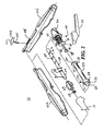
FIG. 2 is a perspective view, with parts separated, of a handle portion of the surgical stapler ofFIG. 1 ; -
FIG. 3 is a perspective view, with parts separated, of a torque limiting mechanism utilized in the handle portion ofFIG. 2 ; -
FIG. 4 is a perspective view of the torque limiting mechanism ofFIG. 3 ; -
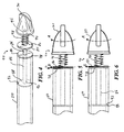
FIG. 5 is a side view of the torque limiting mechanism ofFIG. 4 with friction or pressure plates engaged; -
FIG. 6 is a side view similar toFIG. 5 with the friction plates slipping relative to each other; -
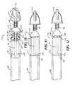
FIG. 7 is a perspective view of an alternative embodiment of a torque limiting mechanism for use in the surgical stapler ofFIG. 1 ; -
FIG. 8 is a side view of the torque limiting mechanism ofFIG. 7 with a driven plate and drive plate engaged; -
FIG. 9 is a view similar toFIG. 8 with the drive and driven plates disengaged; -
FIG. 10 is a perspective view of a further alternative embodiment of a torque limiting mechanism for use with the surgical stapler ofFIG. 1 ; -
FIG. 11 is a side view of the torque limiting mechanism ofFIG. 10 with a driven plate and drive plate engaged; and -
FIG. 12 is a view similar toFIG. 11 with the drive and driven plates disengaged. - Embodiments of the presently disclosed surgical stapling device incorporating tissue compression limiting mechanisms will now be described in detail with reference to the drawings wherein like numerals designate identical or corresponding elements in each of the several views. As is common in the art, the term 'proximal" refers to that part or component closer to the user or operator, i.e. surgeon or physician, while the term "distal" refers to that part or component further away from the user.
- Referring initially to
FIG. 1 there is disclosed asurgical stapling device 10.Surgical stapling device 10 is a circular stapler.Surgical stapling device 10 generally includes ahandle assembly 12 and anelongate body portion 14 extending distally fromhandle assembly 12. Anoperable head assembly 16 is mounted on adistal end 18 ofelongate body portion 14 and generally includes astaple cartridge 20 mounted todistal end 18 ofelongate body portion 14 and ananvil assembly 22 which is movable relative tostaple cartridge 20 in a manner described in more detail hereinbelow.Anvil assembly 22 includes ananvil plate 24 and ananvil shaft 26 extending proximally fromanvil plate 24. A movable anvil retainer orretention shaft 28 extends out ofdistal end 18 ofelongate body portion 14 and is provided to removably receiveanvil shaft 26. Anapproximation knob 30 is rotatably mounted on abody housing 32 ofhandle assembly 12 and is operable to moveanvil assembly 22 relative tostaple cartridge 20 to grasp and compress tissue. - A
trigger 34 is movably mounted to atrigger extension 36 ofbody housing 32. Actuation oftrigger 34 functions to eject staples (not shown) out ofstaple cartridge 20 and intoanvil plate 24. Atrigger lock 38 is movably mounted onbody housing 32 and is provided to block movement oftrigger 34 until manually moved out of the way oftrigger 34 to prevent inadvertent firing. The handle assembly and body housing may be arranged as disclosed inU.S. Patent No. 7,303,106 , the disclosure of which is hereby incorporated by reference herein, in its entirety. The '106 patent also discloses an assembly having a pusher back 186, a cylindrical knife 188 and a staple guide 192. The pusher back is connected to a pusher link 74 and has a plurality of pusher fingers for firing the surgical staples from the staple cartridge. - A
torque limiting mechanism 40 is contained withinbody housing 32 to control the amount of compression applied to tissues captured betweenstaple cartridge 20 andanvil plate 24.Approximation knob 30 is engageable withtorque limiting mechanism 40 such that when tissues compressed betweenstaple cartridge 20 andanvil plate 24 reach a predetermined level of compression,approximation knob 30 slips free of engagement withanvil retention shaft 28 thereby preventing any further compression to the tissue.Torque limiting mechanism 40 includes atorque control 42, extending throughbody housing 32, for presetting the level at whichapproximation knob 30 slips in a manner described hereinbelow. Anindicia plate 44 is mounted onbody housing 32adjacent torque control 42 and includesnumerical indicia 46 to allow the operator to preset the slip point or range ofapproximation knob 30. In this way, the experience of the surgeon can be used to set the instrument according to the type of tissue being stapled or clamped, the age of the patient, the condition of the tissue, or other factors. - Referring now to
FIGS. 1 and2 , in order to moveanvil assembly 22 relative tostaple cartridge 20 in response to rotation of approximation knob 30 (FIG. 1 ), surgical staplinginstrument 10 includes adrive screw 48 and arotatable sleeve 50 mounted inbody housing 32 ofhandle assembly 12. Drivescrew 48 is longitudinally movable withinbody housing 32 and is connected toanvil retention shaft 28. Drivescrew 48 includes a pin 52, positioned through adistal end 54 ofdrive screw 48, which is directly or indirectly connected to theanvil retention shaft 28 in a known manner. For example, in order to transmit longitudinal motion through curvedelongate body portion 14, pin 52 may be connected to proximal ends of bands (not shown) while distal ends of the bands may be connected toanvil retention shaft 28 in a manner described in more detail inU.S. Patent No. 7,303,106 , the disclosure of which is hereby incorporated by reference herein. Thus, longitudinal movement ofdrive screw 48 withinbody housing 32 effects longitudinal movement ofanvil assembly 22 relative tostaple cartridge 20. - As shown,
body housing 32 is provided ascomplementary halves 32a and 32b. Aseal 56 is provided in acircumferential groove 58 formed indistal end 54 of drive screw to prevent escape of insufflation gases and other fluids throughelongate body portion 14 and outbody housing 32. Ascrew stop 64 is provided ondistal end 54 ofdrive screw 48 to limit the longitudinal travel ofdrive screw 48 withinbody housing 32. Ahelical groove 60 is provided in a proximal portion 62 ofdrive screw 48 and is engaged byrotatable sleeve 50 in order to movedrive screw 48 longitudinally. - Specifically, drive
screw 48 is positioned within abore 66 formed withinrotatable sleeve 50. Anenlarged collar 68 rotatably supportsrotatable sleeve 50 withinbody housing 32. In order to movedrive screw 48 longitudinally within bore 66 ofrotatable sleeve 50, a drive pin 70 extends through ahole 72 formed throughenlarged collar 68 and extends intobore 66. Drive pin 70 rides withinhelical groove 60 formed in proximal portion 62 ofdrive screw 48. Thus, asrotatable sleeve 50 is rotated withinbody housing 32, drive pin 70 rides within helical groove 62 drawing and/or advancingdrive screw 48 withinbody housing 32. As noted herein above, drivescrew 48 is connected toanvil assembly 22. Longitudinal movement ofdrive screw 48 withinbody housing 32 effects longitudinal movement ofanvil assembly 22 relative tostaple cartridge 20. - As
approximation knob 30 is rotated, rotational force or torque is applied torotatable sleeve 50 to rotaterotatable sleeve 50 and move drive pin 70 withinhelical groove 60 indrive screw 48. The rotational force is converted to longitudinal or linear force movinganvil assembly 22 towardstaple cartridge 20 thereby compressing tissue captured between anvil and staple cartridge in response to rotation ofapproximation knob 30. - In the absence of any control or limiting factors, as continued torque is applied to
rotatable sleeve 50, an increasing amount of linear force is transmitted to, or exerted on,anvil assembly 22 thereby applying an increasing amount of compression to the tissue captured betweenanvil plate 24 ofanvil assembly 22 andstaple cartridge 20. In order to prevent over compression or under compression,torque limiting mechanism 40 is provided to limit the amount of torque applied torotatable sleeve 50, and thus the amount of linear force applied toanvil assembly 22, to a predetermined or adjustable level. - Referring now to
FIGS. 2 and3 , enlargedcollar 68, which supportsrotatable sleeve 50 within body housing 32 (FIG. 2 ) is located at a distal end 74 ofrotatable sleeve 50. In order for the surgeon to manually rotaterotatable sleeve 50, aproximal end 76 ofrotatable sleeve 50 is provided with a driven member ordisk 78 having a drivensurface 80.Driven disk 78 forms a part oftorque limiting mechanism 40. As noted herein above,approximation knob 30 is provided onbody housing 32 and is rotatable to affect movement ofanvil assembly 22. As shown,torque limiting mechanism 40 is located betweenapproximation knob 30 androtatable sleeve 50.Torque limiting mechanism 40 is provided to limit the amount of rotational torque applied torotatable sleeve 50 in order to control the amount of linear force, and thus tissue compression, applied toanvil assembly 22. - Referring to
FIGS. 2 ,3 and4 , in this embodiment,torque limiting mechanism 40 further includes a driving member ordisk 82 having a drivingsurface 84. Drivingsurface 84 is provided to fictionally engage drivensurface 80 of drivendisk 78 in order to rotaterotatable sleeve 50. The driving member ordisk 82 is also attached to theknob 30. Drivingdisk 82 is mounted on adrive shaft 86. Driveshaft 86 includes asupport disk 88 provided at adistal end 90 ofdriveshaft 86.Support disk 88 is rotatably supported within acircumferential groove 92 formed in rotatable sleeve 50 (FIGS. 3 and4 ). Aproximal end 94 ofdriveshaft 86 is affixed toapproximation knob 30. Specifically,proximal end 94 ofdrive shaft 86 is fixed within ahole 96 formed inapproximation knob 30. Therefore, asapproximation knob 30 is rotated, drivingdisk 82 oftorque limiting mechanism 40 frictionally engages and rotates drivendisk 78 oftorque limiting mechanism 40 provided onrotatable sleeve 50. -
Torque limiting mechanism 40 further includes a biasingspring 98 which is provided betweenapproximation knob 30 and drivingdisk 82 to bias drivingdisk 82 into frictional engagement with drivendisk 78. Driveshaft 86 extends through ahole 100 in drivingdisk 82. While not specifically shown, drivingdisk 82 is keyed (such as with a pin) or otherwise mounted ondrive shaft 86 such that drivingdisk 82 rotates withdrive shaft 86 and is free to move longitudinally alongdrive shaft 86 in order to disengage from or slipped relative to drivendisk 78. - As noted herein above, torque control 42 (
FIGS. 1 and2 ) is provided onbody housing 32 to adjustably control the amount of compressive forces applied to tissue betweenstaple cartridge 20 andanvil assembly 22. Referring for the moment toFIG. 2 ,torque control 42 includes aslide 102 which may be manually graspable and extend outside ofbody housing 32 to be locatedadjacent indicia plate 44. A member or hook 104 extends fromslide 102 and engages coils such as, for example, coils 106, 108, etc., of biasingspring 98 to adjust the amount of spring pressure applied to drivingdisk 82. Thetorque control 42 adjusts the pressure applied by the driving member to the driven member. In this manner,torque control 42 is able to preset the maximum amount of pressure applied to driven member ordisk 78 by driving member ordisk 82. This pre-sets a maximum amount of torque to be applied torotatable sleeve 50 and thus the maximum amount of compressive forces to be applied to tissue captured betweenstaple cartridge 20 andanvil assembly 22. - It should be noted that, while
torque limiting mechanism 40 includes a biasingspring 98 to bias drivingdisk 82 into engagement with drivendisk 78,torque limiting mechanism 40 may omit biasingspring 98. In this configuration, drivensurface 80 of drivendisk 78 and drivingsurface 84 of drivingdisk 82 may be manufactured with predetermined coefficients of friction such that drivingdisk 82 slips relative to drivendisk 78 at a predetermined torque limit. - Referring now to
FIGS. 1 ,2 ,5 and 6 , the use oftorque limiting mechanism 40 to limit the amount of rotational force or torque applied torotatable sleeve 50 will now be described. Referring initially toFIGS. 1 and2 ,torque control 42 is adjusted such that hook 104 applies the desired amount of preload pressure to biasingspring 98. This is accomplished by a slidingslide 102 relative to indicia plate 44 untilslide 102 is aligned with the appropriatenumerical indicia 46 onindicia plate 44. Thereafter,approximation knob 30 is rotated in the direction of arrow A (FIG. 5 ) to drawanvil assembly 22 towardstaple cartridge 20 thereby compressing first and second tissue sections T1 and T2 together and bring the tissue sections into position to be stapled. - Referring specifically to
FIG. 5 , rotation ofapproximation knob 30 in the direction of arrow A rotates drivingdisk 82 in the direction of arrowB. Driving disk 82's frictional engagement with driven disk 70 rotates drivendisk 78 in the direction of arrow C thereby rotatingrotatable sleeve 50 to compress the tissue sections as described hereinabove. - Referring now to
FIG. 6 , asapproximation knob 30 continues to be rotated, the increasing compression of first and second tissue sections T1 and T2 requires an increasing amount of linear force passing throughdrive screw 48 and thus an increasing amount of rotational torque required byrotatable sleeve 50. At the predetermined amount of pressure applied by biasingspring 98 and controlled bytorque control 42, the frictional forces between drivendisk 78 and drivingdisk 82 are overcome allowing drivingdisk 82 to slip relative to drivendisk 78. As drivingdisk 82 slips relative to drivendisk 78, no further increasing amount of torque is applied torotatable sleeve 50 and thus no further increasing amount of linear force is transmitted throughdrive screw 48 toanvil assembly 22. In this manner,torque limiting mechanism 40 prevent over compression of tissues captured betweenanvil assembly 22 andstaple cartridge 20. - Referring now to
FIGS. 7-9 , and initially with regard toFIG. 7 , there is disclosed an alternative embodiment of atorque limiting mechanism 110 for use withsurgical stapling device 10 described herein above. Similar totorque limiting mechanism 40 described above,torque limiting mechanism 110 generally includes a driven member ordisk 112 provided onproximal end 76 ofrotatable sleeve 50 and a driving member ordisk 114 mounted for longitudinal movement along adriveshaft 116. A biasingspring 118 is provided arounddrive shaft 116 andbiases driving disk 114 into engagement with drivendisk 112. Similar to drivingdisk 82 described herein above, drivingdisk 114 is mounted for rotational movement along withdrive shaft 116 and is free to move longitudinally alongdrive shaft 116 against the bias of biasingspring 118. - A
support disc 120 is provided on adistal end 122 ofdrive shaft 116 and is rotatably supported withincircumferential groove 92 inrotatable sleeve 50. Aproximal end 124 ofdrive shaft 116 is affixed withinhole 96 inapproximation knob 30. Thus, rotation ofapproximation knob 30 rotates driveshaft 116 and thus drivingdisk 114. In this embodiment, drivendisk 112 is provided with a plurality of pawls or drivendisk teeth 126 which are mechanically interengageable with a plurality of corresponding pawls or drivingdisk teeth 128 formed on drivingdisk 114.Driven disk teeth 126 and drivingdisk teeth 128 form respective driven and drivingsurfaces 130 and 132 on drivendisk 112 and drivingdisk 114. - Referring now to
FIGS. 8 and 9 , in use, biasingspring 118biases driving disk 114 into engagement with drivendisk 112. Specifically, biasingspring 118biases driving surface 132, including drivingteeth 128, into engagement with driven surface 130, including driventeeth 126. In a manner identical to that described herein above,torque control 42 is manipulated to adjust the maximum amount of force applied by biasingspring 118 to drivingdisk 114. Asapproximation knob 30 is rotated, drivingteeth 128 on drivingdisk 114 are interengaged with driventeeth 126 on drivendisk 112 to thereby rotaterotatable sleeve 50. As further noted herein above, rotation ofrotatable sleeve 50 effects longitudinal movement ofanvil assembly 22 relative tostaple cartridge 20 to thereby compress tissue. - With specific reference to
FIG. 9 , asrotatable sleeve 50 is rotated, an increasing amount of force is required to continue to rotaterotatable sleeve 50 due to the compressive forces existing between the tissues. Continued rotation ofapproximation knob 30 continues to apply torqued torotatable sleeve 50 until such time as the amount of torque required exceeds the pressure applied to drivingdisk 114 by biasingspring 118. At this point, drivingdisk 114 "slips" relative to drivingdisk 112 and moves proximally in the direction of arrow D against the bias of biasingspring 118. Specifically, drivingteeth 128 on drivingdisk 114 slip relative to or are disengaged from driventeeth 126 on drivendisk 112 thereby preventing any further application of increased torque torotatable sleeve 50. In this manner,torque limiting mechanism 110 prevents over compression of tissues captured betweenanvil assembly 22 andstaple cartridge 20. - Referring now to
FIGS. 10-12 , and initially with regard toFIG. 10 , there is disclosed a further alternative embodiment of atorque limiting mechanism 140 for use withsurgical stapling device 10. Similar totorque limiting mechanism 40 described above,torque limiting mechanism 140 generally includes a driven member ordisk 142 provided onproximal end 76 ofrotatable sleeve 50 and a cone shaped driving member ordisk 144 mounted for longitudinal movement along adrive shaft 146. A biasingspring 148 is provided arounddrive shaft 146 andbiases driving disk 144 into engagement with drivendisk 142. Similar to drivingdisk 82 described herein above, drivingdisk 144 is mounted for rotational movement along withdrive shaft 146 and is free to move longitudinally alongdrive shaft 146 against the bias of biasingspring 148. - A
support disc 150 is provided on adistal end 152 ofdrive shaft 146 and is rotatably supported withincircumferential groove 92 inrotatable sleeve 50. Aproximal end 154 ofdriveshaft 146 is affixed withinhole 96 inapproximation knob 30. Thus, rotation ofapproximation knob 30 rotates driveshaft 146 and thus drivingdisk 144. In this embodiment, drivendisk 142 includes a drivendisk surface 156 and drivingdisk 144 includes adriving disk surface 158. At least onereleasable connector 160 is provided between drivendisk surface 156 and drivingdisk surface 158.Releasable connector 160 slips relative to drivendisk surface 156 and\or drivingdisk surface 158 when a preset amount of torque is applied torotatable sleeve 50. - In this specific embodiment,
releasable connectors 160 are in the form of a plurality of connectingballs 162.Driven disk surface 156 of drivendisk 142 includes a plurality of driven disk cups 164 and drivingdisk surface 158 of drivingdisk 144 includes a plurality of correspondingdriving disk cups 166. Connectingballs 162 are movably supported between driven disk cups 164 and drivingdisk cups 166. Connectingballs 162 are maintained betweendriving disk cups 164 and driven disk cups 166 by the biasing pressure of biasingspring 148 on drivingdisk 144. - Referring now to
FIGS. 11 and 12 , in use,approximation knob 30 is rotated such thatdriving disk 144 rotates drivendisk 142 through connectingballs 162. Rotation of drivendisk 142 correspondingly rotatesrotatable sleeve 50 thereby effecting longitudinal movement betweenanvil assembly 22 and staple cartridge 20 (FIG. 1 ). Asanvil assembly 22 moves towardsstaple cartridge 20 to compress the tissues there between, an increasing amount of rotational force or torque is required to be applied torotatable sleeve 50. - As best shown in
FIG. 12 , an increasing amount of rotational force is required to be applied toapproximation knob 30 to continue rotation ofrotatable sleeve 50. When the force needed to continue rotation arotatable sleeve 50 exceeds that preset bytorque control 42, drivingdisk 144 moves proximally against the bias of biasingspring 148. This causes connectingballs 162 to slit or "pop" out of drivingdisk cups 166 thereby removing any further rotational force applied to drivendisk 142. Alternatively, while not specifically shown, connectingballs 162 may be firmly affixed within drivingdisk cups 166 in drivingdisk 144 such that releasable connectingballs 162 slip or pop out of driven disk cups 164 in drivendisk 142 as drivingdisk 144 moved proximally against the pressure of biasingspring 140. In this manner,torque limiting mechanism 140 prevents over compression of tissues captured betweenanvil assembly 22 andstaple cartridge 20 ofsurgical stapling device 10. - In further embodiments of the present disclosure, the body housing and handle assembly can incorporate a motorized actuator and may be connected to, or incorporate therein, a power source. An example of a powered, motorized device is disclosed in International Publication No.
WO 09/039506 U.S. patent No. 7,032,798 , the disclosures of which are hereby incorporated by reference herein, in their entirety. The manually powered device discussed above converts the pivoting motion of the handle into linear motion of the anvil retention shaft. A motorized device can generate rotational motion, which is then converted to linear motion for clamping tissue, firing staples, and/or cutting tissue. - It will be understood that various modifications may be made to the embodiments disclosed herein. For example, alternative disconnecting mechanisms may be provided such as, for example, multiple friction plates, magnetic engagement mechanisms, etc. Further, the disclosed torque limiting mechanisms may find application in any surgical instrumentation incorporating tissue compression structure. Additionally, the disclosed torque limiting mechanisms may be provided as modular and interchangeable components having differing ranges of engagement pressures for use in surgical instruments. In addition, one or more removable adapters having an elongate shaft extending from the handle assembly to the distal end of the device can be used. Such adapters can have flexible shafts, curved, or other shapes, and may be designed to connect to various end effectors. Such adapters can also be designed to be connected to a manually driven handle assembly, a motorized actuator, or both. An adapter is disclosed in
U.S. Patent No. 7,922,063 , the disclosure of which is hereby incorporated by reference herein, in its entirety. Therefore, the above description should not be construed as limiting, but merely as exemplifications of particular embodiments. Those skilled in the art will envision other modifications within the scope and spirit of the claims appended hereto. The invention may be described by reference to the following numbered paragraphs:- - 1. A torque limiting mechanism for use in a surgical instrument that compresses tissue comprising:
- a driven member engageable with an approximating mechanism of a surgical instrument, the driven member having a driven surface: and
- a driving member having a driving surface engageable with the driven surface of the driven member and connected to the clamping actuator of the instrument, wherein the driving surface of the driving member slips relative to the driven surface of the driven member at a predetermined engagement pressure; and
- a torque control having a member that adjusts the pressure applied by the driving member to the driven member.
- 2. The torque limiting mechanism as recited in paragraph 1, wherein driving member is rotatable relative to the driven member.
- 3. The torque limiting mechanism as recited in
paragraph 2, wherein the driving surface frictionally engages the driven surface. - 4. The torque limiting mechanism as recited in
paragraph 2, wherein the driving surface and the driven surface have interengaging structure. - 5. The torque limiting mechanism as recited in paragraph 4, wherein the driving surface and the driven surface have interengaging teeth.
- 6. The torque limiting mechanism as recited in paragraph 4, wherein the interengaging structure is a detent mechanism.
- 7. The torque limiting mechanism as recited in paragraph 6, further comprising at least one movable connector between the driving surface and the driven surface.
- 8. The torque limiting mechanism as recited in paragraph 6, wherein at least one of the driving surface and driven surface includes cups and the other of the driving surface and driven surface supports balls removalbly engageable with the cups.
- 9. The torque limiting mechanism as recited in
paragraph 2, further comprising a spring engageable with the driving member, wherein the driving member is spring biased into engagement with the driven member. - 10. The torque limiting mechanism as recited in paragraph 9, wherein the member of the torque control engages with the biasing spring.
- 11. The torque limiting mechanism as recited in
paragraph 10, wherein the torque control includes a hook engageable with the biasing spring and a slide member. - 12. A surgical instrument comprising:
- a body portion;
- a first clamping member mounted on the body portion and a second clamping member movable relative to the first clamping member;
- an approximating mechanism for moving the second clamping member relative to the first clamping member, the approximating mechanism including a longitudinally movable drive screw having a helical groove formed therein and a rotatable sleeve mounted about the drive screw, the rotatable sleeve including a drive pin extending into the helical groove such that rotation of the rotatable sleeve longitudinally translates the drive screw within the body portion;
- a torque limiting mechanism engageable with the rotatable sleeve, wherein at least a portion of the torque limiting mechanism slips relative to the rotatable sleeve at a predetermined engagement pressure.
- 13. The surgical instrument as recited in
paragraph 12, wherein the torque limiting mechanism includes a driven surface affixed to the rotatable sleeve and a driving surface engageable with the driven surface. - 14. The surgical instrument as recited in paragraph 13, wherein the driving surface frictionally engages the driven surface.
- 15. The surgical instrument as recited in paragraph 13, wherein the driving surface and the driven surface have interengaging structure.
- 16. The surgical instrument as recited in paragraph 15, wherein the driving surface and the driven surface have interengaging teeth.
- 17. The surgical instrument as recited in paragraph 15, wherein the interengaging structure is a detent mechanism.
- 18. The surgical instrument as recited in paragraph 17, wherein at least one of the driving surface and driven surface includes cups and the other of the driving surface and driven surface supports balls removalbly engageable with the cups.
- 19. The surgical instrument as recited in
paragraph 12, further comprising a spring engageable with the driving member, wherein the driving member is spring biased into engagement with the driven member. - 20. A method of preventing over compression of tissue between first and second clamping members of a surgical instrument comprising:
- providing a surgical instrument including a body portion; a first clamping member mounted on the body portion and a second clamping member movable relative to the first clamping member;
- an approximating mechanism for moving the second clamping member relative to the first clamping member, the approximating mechanism including a longitudinally movable drive screw having a helical groove formed therein and a rotatable sleeve mounted about the drive screw, the rotatable sleeve including a drive pin extending into the helical groove such that rotation of the rotatable sleeve longitudinally translates the drive screw within the body portion and an approximation knob engageable with the rotatable sleeve;
- a torque limiting mechanism engageable with the rotatable sleeve;
- rotating the approximation knob to rotate rotatable sleeve such that at least a portion of the torque limiting mechanism slips relative to the rotatable sleeve at a predetermined engagement pressure.
Claims (15)
a torque limiting mechanism engageable with the rotatable sleeve, wherein at least a portion of the torque limiting mechanism slips relative to the rotatable sleeve at a predetermined engagement pressure.
Priority Applications (1)
| Application Number | Priority Date | Filing Date | Title |
|---|---|---|---|
| EP16201641.4A EP3158951A1 (en) | 2011-04-29 | 2012-04-27 | Circular stapler with controlled tissue compression |
Applications Claiming Priority (1)
| Application Number | Priority Date | Filing Date | Title |
|---|---|---|---|
| US13/097,242 US8490850B2 (en) | 2011-04-29 | 2011-04-29 | Circular stapler with controlled tissue compression |
Related Child Applications (2)
| Application Number | Title | Priority Date | Filing Date |
|---|---|---|---|
| EP16201641.4A Division EP3158951A1 (en) | 2011-04-29 | 2012-04-27 | Circular stapler with controlled tissue compression |
| EP16201641.4A Division-Into EP3158951A1 (en) | 2011-04-29 | 2012-04-27 | Circular stapler with controlled tissue compression |
Publications (3)
| Publication Number | Publication Date |
|---|---|
| EP2517650A2 true EP2517650A2 (en) | 2012-10-31 |
| EP2517650A3 EP2517650A3 (en) | 2014-12-03 |
| EP2517650B1 EP2517650B1 (en) | 2017-01-18 |
Family
ID=46062078
Family Applications (2)
| Application Number | Title | Priority Date | Filing Date |
|---|---|---|---|
| EP12165923.9A Active EP2517650B1 (en) | 2011-04-29 | 2012-04-27 | Circular stapler with controlled tissue compression |
| EP16201641.4A Withdrawn EP3158951A1 (en) | 2011-04-29 | 2012-04-27 | Circular stapler with controlled tissue compression |
Family Applications After (1)
| Application Number | Title | Priority Date | Filing Date |
|---|---|---|---|
| EP16201641.4A Withdrawn EP3158951A1 (en) | 2011-04-29 | 2012-04-27 | Circular stapler with controlled tissue compression |
Country Status (7)
| Country | Link |
|---|---|
| US (3) | US8490850B2 (en) |
| EP (2) | EP2517650B1 (en) |
| JP (2) | JP6045172B2 (en) |
| CN (2) | CN106108967B (en) |
| AU (3) | AU2012201688B2 (en) |
| CA (1) | CA2772423A1 (en) |
| ES (1) | ES2616211T3 (en) |
Cited By (4)
| Publication number | Priority date | Publication date | Assignee | Title |
|---|---|---|---|---|
| ITRM20130217A1 (en) * | 2013-04-10 | 2014-10-11 | Longo Antonio | SURGICAL SUTURATOR |
| EP3461430A1 (en) * | 2017-09-27 | 2019-04-03 | Ethicon LLC | Circular stapling instrument with torque limiting feature |
| EP3900645A4 (en) * | 2018-12-18 | 2022-02-16 | Touchstone International Medical Science Co., Ltd. | Knob assembly and round tube type stapler |
| RU2775540C1 (en) * | 2018-12-18 | 2022-07-04 | Тачстоун Интернэшнл Медикал Сайенс Ко., Лтд. | Handle assembly and circular stapler |
Families Citing this family (143)
| Publication number | Priority date | Publication date | Assignee | Title |
|---|---|---|---|---|
| US8408441B2 (en) * | 2009-01-06 | 2013-04-02 | Covidien Lp | Surgical stapler |
| US8490850B2 (en) * | 2011-04-29 | 2013-07-23 | Covidien Lp | Circular stapler with controlled tissue compression |
| US9675359B2 (en) * | 2012-10-10 | 2017-06-13 | Covidien Lp | Surgical instrument with preload assembly |
| CN104042292A (en) | 2013-03-15 | 2014-09-17 | 柯惠Lp公司 | Surgical anastomosis device comprising assemblies capable of being repeatedly utilized |
| CN104173093B (en) * | 2013-05-22 | 2017-10-13 | 天津瑞奇外科器械股份有限公司 | Ultrasound knife cutter head and ultrasound knife |
| EP3010424A4 (en) | 2013-06-17 | 2017-06-07 | Covidien LP | Surgical instrument with lockout mechanism |
| US9554802B2 (en) | 2013-11-13 | 2017-01-31 | Covidien Lp | Anvil assembly with frangible retaining member |
| US9517070B2 (en) | 2013-11-13 | 2016-12-13 | Covidien Lp | Anvil assembly and delivery system |
| AU2014388236A1 (en) * | 2014-03-26 | 2016-07-21 | Covidien Lp | Surgical stapling apparatus |
| US9913643B2 (en) | 2014-05-09 | 2018-03-13 | Covidien Lp | Interlock assemblies for replaceable loading unit |
| AU2014397432A1 (en) | 2014-06-12 | 2016-12-01 | Covidien Lp | Surgical stapling apparatus |
| US9987099B2 (en) | 2014-06-18 | 2018-06-05 | Covidien Lp | Disposable housings for encasing handle assemblies |
| US9861367B2 (en) | 2014-06-24 | 2018-01-09 | Covidien Lp | Anvil assembly delivery systems |
| US9867619B2 (en) | 2014-06-24 | 2018-01-16 | Covidien Lp | System for delivering an anvil assembly to a surgical site |
| US10405864B2 (en) | 2014-07-04 | 2019-09-10 | Covidien Lp | Loading unit with shipping member for surgical stapling device |
| US9757133B2 (en) | 2014-07-09 | 2017-09-12 | Covidien Lp | Methods and devices for performing a surgical anastomosis |
| US10085744B2 (en) | 2014-12-08 | 2018-10-02 | Covidien Lp | Loading unit attachment band for surgical stapling instrument |
| US9855045B2 (en) | 2014-12-09 | 2018-01-02 | Covidien Lp | Anvil assembly delivery system |
| JP6466580B2 (en) | 2014-12-11 | 2019-02-06 | コヴィディエン リミテッド パートナーシップ | Surgical stapling and loading unit |
| EP3229708B1 (en) | 2014-12-11 | 2019-08-28 | Covidien LP | Stapler with automatic lockout mechanism |
| EP3232946A1 (en) | 2014-12-17 | 2017-10-25 | Covidien LP | Surgical stapling device with firing indicator |
| US10022126B2 (en) | 2015-01-07 | 2018-07-17 | Covidien Lp | Loading unit locking collar |
| US10039549B2 (en) | 2015-01-07 | 2018-08-07 | Covidien Lp | Loading unit retention clip for surgical stapling instrument |
| US10117656B2 (en) | 2015-01-07 | 2018-11-06 | Covidien Lp | Loading unit locking collar |
| JP2018504987A (en) | 2015-02-15 | 2018-02-22 | コヴィディエン リミテッド パートナーシップ | Surgical stapling device having a monolithic firing indicator |
| US10881408B2 (en) | 2015-04-22 | 2021-01-05 | Covidien Lp | Interlock assembly for replaceable loading units |
| US10426480B2 (en) | 2015-04-29 | 2019-10-01 | Covidien Lp | Cutting ring assembly with rigid cutting member |
| US9987001B2 (en) | 2015-06-12 | 2018-06-05 | Covidien Lp | Surgical anastomosis apparatus |
| US9974536B2 (en) | 2015-07-02 | 2018-05-22 | Covidien Lp | Anvil assemblies and delivery systems |
| US10111668B2 (en) | 2015-07-02 | 2018-10-30 | Covidien Lp | Anvil assembly with snap backup ring |
| US10117655B2 (en) | 2015-07-22 | 2018-11-06 | Covidien Lp | Loading unit locking band for surgical stapling instrument |
| US10085756B2 (en) | 2015-07-24 | 2018-10-02 | Covidien Lp | Anvil assembly and anvil assembly delivery system |
| US10117675B2 (en) | 2015-07-28 | 2018-11-06 | Covidien Lp | Trocar tip protector |
| US9980730B2 (en) | 2015-09-21 | 2018-05-29 | Covidien Lp | Loading unit locking collar with rotational actuated release |
| US10111684B2 (en) | 2015-09-25 | 2018-10-30 | Covidien Lp | Adapter assembly including a removable trocar assembly |
| US10542992B2 (en) | 2015-10-19 | 2020-01-28 | Covidien Lp | Loading unit with stretchable bushing |
| WO2017066918A1 (en) | 2015-10-20 | 2017-04-27 | Covidien Lp | Circular stapler with tissue gap indicator assembly |
| AU2015412610A1 (en) | 2015-10-21 | 2018-03-15 | Covidien Lp | Annular knife for surgical stapler |
| US10512466B2 (en) | 2015-11-05 | 2019-12-24 | Covidien Lp | Adapter assembly for surgical device |
| WO2017079970A1 (en) | 2015-11-13 | 2017-05-18 | Covidien Lp | Circular stapler with audible indicator mechanism |
| ES2821891T3 (en) | 2015-12-07 | 2021-04-28 | Covidien Lp | Anvil Assembly and Delivery System |
| US10390835B2 (en) | 2015-12-10 | 2019-08-27 | Covidien Lp | Surgical fastener apparatus with linear position sensor |
| US10524797B2 (en) | 2016-01-13 | 2020-01-07 | Covidien Lp | Adapter assembly including a removable trocar assembly |
| JP6619103B2 (en) | 2016-02-04 | 2019-12-11 | コヴィディエン リミテッド パートナーシップ | Circular stapler with visual indicator mechanism |
| US10603042B2 (en) | 2016-02-10 | 2020-03-31 | Covidien Lp | Flexible circular stapler |
| US10398439B2 (en) | 2016-02-10 | 2019-09-03 | Covidien Lp | Adapter, extension, and connector assemblies for surgical devices |
| US10595871B2 (en) | 2016-05-10 | 2020-03-24 | Covidien Lp | Insertion instrument, adapter assemblies and protector assemblies for a flexible circular stapler |
| US11141162B2 (en) | 2016-07-08 | 2021-10-12 | Covidien Lp | Loading unit locking collar with linearly actuated release |
| US11452522B2 (en) | 2016-08-15 | 2022-09-27 | Covidien Lp | Circular stapling device with articulating anvil retainer assembly |
| US10390834B2 (en) | 2016-09-27 | 2019-08-27 | Ethicon Llc | Circular surgical staplers with isolating sleeves stored inside anvil |
| US10499922B2 (en) | 2016-11-04 | 2019-12-10 | Covidien Lp | Stapling device with self-releasing knife carrier pusher |
| US10426470B2 (en) | 2016-11-04 | 2019-10-01 | Covidien Lp | Stapling device with releasable knife carrier |
| US10542981B2 (en) * | 2016-11-14 | 2020-01-28 | Ethicon Llc | Atraumatic stapling head features for circular surgical stapler |
| US11241232B2 (en) | 2017-01-24 | 2022-02-08 | Covidien Lp | Surgical stapling device with resettable anvil assembly |
| US11678885B2 (en) | 2017-01-25 | 2023-06-20 | Covidien Lp | Circular stapling device and method of use |
| US10542993B2 (en) | 2017-02-24 | 2020-01-28 | Covidien Lp | Anvil assembly of circular stapling device including alignment splines |
| WO2018161301A1 (en) | 2017-03-09 | 2018-09-13 | Covidien Lp | End effector assembly for circular stapler apparatus |
| WO2018161314A1 (en) | 2017-03-09 | 2018-09-13 | Covidien Lp | Surgical stapling device with audible indicator mechanism |
| CN110461253B (en) | 2017-03-23 | 2023-03-10 | 柯惠有限合伙公司 | Circular suturing device with aligned splines |
| US10342534B2 (en) | 2017-03-23 | 2019-07-09 | Covidien Lp | Surgical stapling device with releasable knife carrier |
| US10881409B2 (en) | 2017-05-02 | 2021-01-05 | Covidien Lp | Rotation assembly for a surgical device |
| US10932784B2 (en) | 2017-06-09 | 2021-03-02 | Covidien Lp | Handheld electromechanical surgical system |
| US11045199B2 (en) | 2017-06-09 | 2021-06-29 | Covidien Lp | Handheld electromechanical surgical system |
| US11596400B2 (en) | 2017-06-09 | 2023-03-07 | Covidien Lp | Handheld electromechanical surgical system |
| US10987107B2 (en) | 2017-07-05 | 2021-04-27 | Covidien Lp | Surgical stapling device |
| US11090054B2 (en) | 2017-08-07 | 2021-08-17 | Covidien Lp | Stapling device with resettable tilt anvil assembly |
| US10828026B2 (en) | 2017-08-08 | 2020-11-10 | Covidien Lp | Tiltable anvil assembly |
| US10695069B2 (en) | 2017-08-23 | 2020-06-30 | Covidien Lp | Circular stapling device with offset spline tip |
| WO2019041315A1 (en) | 2017-09-01 | 2019-03-07 | Covidien Lp | Circular stapling device with position ribs |
| US11324507B2 (en) | 2017-11-03 | 2022-05-10 | Covidien Lp | Device and method for attachment of a stomal sleeve |
| CN110115605B (en) * | 2018-02-06 | 2022-08-26 | 上海梵焜医疗器械有限公司 | Linear type stitching instrument |
| US11497501B2 (en) | 2018-03-26 | 2022-11-15 | Covidien Lp | Circular stapling device with A-frame splines |
| US10952734B2 (en) | 2018-04-23 | 2021-03-23 | Covidien Lp | Stapling device with cut ring biasing member |
| US11197676B2 (en) | 2018-06-28 | 2021-12-14 | Covidien Lp | Tie-down method for anvil assembly delivery system |
| US11241234B2 (en) | 2018-08-14 | 2022-02-08 | Covidien Lp | Anvil assembly with self-retaining backup member |
| US11564691B2 (en) | 2018-08-24 | 2023-01-31 | Covidien Lp | Powered circular stapling device |
| US10973544B2 (en) | 2018-10-02 | 2021-04-13 | Covidien Lp | Retaining mechanism for trocar assembly |
| US11141163B2 (en) | 2018-10-04 | 2021-10-12 | Covidien Lp | Circular stapling device with anvil rotation locking structure |
| US11065005B2 (en) | 2018-11-07 | 2021-07-20 | Covidien Lp | Reload assembly for a circular stapling device |
| US11147561B2 (en) | 2018-11-28 | 2021-10-19 | Covidien Lp | Reload assembly for a circular stapling device |
| US11389263B2 (en) | 2018-12-13 | 2022-07-19 | Covidien Lp | Lockout mechanisms for surgical instruments |
| WO2020125677A1 (en) * | 2018-12-18 | 2020-06-25 | 天臣国际医疗科技股份有限公司 | Rotary knob assembly and circular-tube-type stapler |
| WO2020125675A1 (en) * | 2018-12-18 | 2020-06-25 | 天臣国际医疗科技股份有限公司 | Knob assembly and cylindrical anastomat |
| US11701109B2 (en) | 2018-12-28 | 2023-07-18 | Cilag Gmbh International | Surgical stapler with sloped staple deck for varying tissue compression |
| US11166728B2 (en) | 2019-02-08 | 2021-11-09 | Covidien Lp | Reload assembly for a circular stapling device |
| US11547411B2 (en) | 2019-02-22 | 2023-01-10 | Covidien Lp | Anastomosis wound protector |
| US11529144B2 (en) | 2019-02-22 | 2022-12-20 | Covidien Lp | Encapsulated plug assembly for electromechanical surgical devices |
| US11331782B2 (en) | 2019-03-01 | 2022-05-17 | Covidien Lp | Reload assembly for a circular stapling device |
| US11337701B2 (en) | 2019-03-01 | 2022-05-24 | Covidien Lp | Devices and methods for assembling adapter assemblies |
| US11457921B2 (en) | 2019-03-26 | 2022-10-04 | Covidien Lp | Anvil assembly for surgical stapling instrument |
| US11596410B2 (en) | 2019-04-05 | 2023-03-07 | Covidien Lp | Surgical stapling device |
| US11534164B2 (en) | 2019-04-05 | 2022-12-27 | Covidien Lp | Strain gauge stabilization in a surgical device |
| US11419631B2 (en) | 2019-04-16 | 2022-08-23 | Covidien Lp | Trocar assemblies for adapter assemblies for surgical stapling instruments |
| US11317945B2 (en) | 2019-04-16 | 2022-05-03 | Covidien Lp | Trocar assemblies for adapter assemblies for surgical stapling instruments |
| US11344330B2 (en) | 2019-04-16 | 2022-05-31 | Covidien Lp | Trocar assemblies for adapter assemblies for surgical stapling instruments |
| US11660116B2 (en) | 2019-04-16 | 2023-05-30 | Covidien Lp | Trocar assemblies for adapter assemblies for surgical stapling instruments |
| US11839378B2 (en) | 2019-04-19 | 2023-12-12 | Covidien Lp | Circular stapling instruments |
| US11399838B2 (en) | 2019-04-22 | 2022-08-02 | Covidien Lp | Reload assembly for circular stapling devices |
| US11246599B2 (en) | 2019-04-25 | 2022-02-15 | Covidien Lp | End effector for circular stapling instrument |
| JP2022543958A (en) | 2019-05-31 | 2022-10-17 | コヴィディエン リミテッド パートナーシップ | circular stapling device |
| US11690624B2 (en) | 2019-06-21 | 2023-07-04 | Covidien Lp | Reload assembly injection molded strain gauge |
| US11123101B2 (en) | 2019-07-05 | 2021-09-21 | Covidien Lp | Retaining mechanisms for trocar assemblies |
| US11446035B2 (en) | 2019-06-24 | 2022-09-20 | Covidien Lp | Retaining mechanisms for trocar assemblies |
| US11357509B2 (en) | 2019-07-11 | 2022-06-14 | Covidien Lp | Reload assembly for a circular stapling device |
| US11192227B2 (en) | 2019-07-16 | 2021-12-07 | Covidien Lp | Reload assembly for circular stapling devices |
| US11464510B2 (en) | 2019-07-26 | 2022-10-11 | Covidien Lp | Reload assembly with knife carrier lockout |
| US11253255B2 (en) | 2019-07-26 | 2022-02-22 | Covidien Lp | Knife lockout wedge |
| US11399825B2 (en) | 2019-10-28 | 2022-08-02 | Covidien Lp | Reload assembly with knife carrier lockout |
| US11553918B2 (en) | 2019-12-16 | 2023-01-17 | Covidien Lp | Reload assembly with knife carrier lockout |
| US11730481B2 (en) | 2020-01-06 | 2023-08-22 | Covidien Lp | Assemblies for retaining a trocar assembly |
| US11517317B2 (en) | 2020-01-06 | 2022-12-06 | Covidien Lp | Trocar release assemblies for a surgical stapler |
| US11911038B2 (en) | 2020-01-13 | 2024-02-27 | Covidien Lp | Cut optimization for excessive tissue conditions |
| US11523828B2 (en) | 2020-01-28 | 2022-12-13 | Covidien Lp | Sealed reload assembly for stapling device |
| US11622767B2 (en) | 2020-02-19 | 2023-04-11 | Covidien Lp | Sealed trocar assembly for stapling device |
| US11547438B2 (en) | 2020-02-24 | 2023-01-10 | Covidien Lp | Tip protector for ensuring trocar insertion |
| US11382630B2 (en) | 2020-02-25 | 2022-07-12 | Covidien Lp | Surgical stapling device with two part knife assembly |
| US11779343B2 (en) | 2020-02-26 | 2023-10-10 | Covidien Lp | Staple reload assembly with releasable knife |
| US11298152B2 (en) | 2020-02-28 | 2022-04-12 | Covidien Lp | Trocar retaining mechanism including band support |
| US11272998B2 (en) | 2020-03-04 | 2022-03-15 | Covidien Lp | Strain gage fixation in tension |
| US11350939B2 (en) | 2020-03-24 | 2022-06-07 | Covidien Lp | Retaining mechanisms for trocar assemblies |
| US11426169B2 (en) | 2020-03-24 | 2022-08-30 | Covidien Lp | Retaining mechanisms for trocar assemblies |
| US11426170B2 (en) | 2020-03-24 | 2022-08-30 | Covidien Lp | Retaining mechanisms for trocar assemblies |
| US11653925B2 (en) | 2020-05-21 | 2023-05-23 | Covidien Lp | Tissue relaxation monitoring for optimized tissue stapling |
| US11547405B2 (en) | 2020-05-22 | 2023-01-10 | Covidien Lp | Surgical stapling device |
| US11553921B2 (en) | 2020-07-15 | 2023-01-17 | Covidien Lp | Surgical stapling device with flexible shaft |
| US11547412B2 (en) | 2020-07-22 | 2023-01-10 | Covidien Lp | Surgical instruments and methods of assembly |
| US11877744B2 (en) | 2020-08-14 | 2024-01-23 | Covidien Lp | Low-cost powered stapler with end stop selection |
| US11627966B2 (en) | 2020-08-26 | 2023-04-18 | Covidien Lp | Surgical stapling device |
| US11801054B2 (en) | 2020-09-22 | 2023-10-31 | Covidien Lp | Surgical stapler with oval tool assembly |
| US11712509B2 (en) | 2020-10-02 | 2023-08-01 | Covidien Lp | Seal assembly for circular stapling instrument |
| US11627967B2 (en) | 2020-11-23 | 2023-04-18 | Covidien Lp | Trans-anastomotic insertion device |
| US11877750B2 (en) | 2021-01-21 | 2024-01-23 | Covidien Lp | Surgical stapler with powered and manual functions |
| CN112716618B (en) * | 2021-01-25 | 2022-03-01 | 苏州法兰克曼医疗器械有限公司 | Safety mechanism of cutting anastomat executing assembly |
| US11786241B2 (en) | 2021-02-16 | 2023-10-17 | Covidien Lp | Surgical stapling device including a hydraulic staple formation mechanism |
| US11553920B2 (en) | 2021-05-03 | 2023-01-17 | Covidien Lp | Trocar retainer assembly for surgical stapler |
| US11490894B1 (en) | 2021-05-12 | 2022-11-08 | Covidien Lp | Surgical device with grease filter |
| US11642131B2 (en) | 2021-05-17 | 2023-05-09 | Covidien Lp | Devices and methods for shortening a rectal stump during a lower anterior resection procedure |
| US11612400B2 (en) | 2021-05-24 | 2023-03-28 | Covidien Lp | Trocar assembly with bearing assembly for load sharing |
| US11819208B2 (en) | 2021-08-05 | 2023-11-21 | Covidien Lp | Handheld electromechanical surgical device with strain gauge drift detection |
| US11744592B2 (en) | 2021-08-05 | 2023-09-05 | Covidien Lp | Handheld electromechanical stapler with tissue thickness detection |
| US11737759B2 (en) | 2021-08-05 | 2023-08-29 | Covidien Lp | Surgical stapling device accommodating prolapsed tissue |
| US11883028B2 (en) | 2021-09-08 | 2024-01-30 | Covidien Lp | Systems and methods for post-operative anastomotic leak detection |
| US11717299B2 (en) | 2021-10-12 | 2023-08-08 | Covidien Lp | Surgical stapling device with probiotics |
Citations (10)
| Publication number | Priority date | Publication date | Assignee | Title |
|---|---|---|---|---|
| US4473077A (en) | 1982-05-28 | 1984-09-25 | United States Surgical Corporation | Surgical stapler apparatus with flexible shaft |
| US4576167A (en) | 1981-09-03 | 1986-03-18 | United States Surgical Corporation | Surgical stapler apparatus with curved shaft |
| US5005749A (en) | 1988-07-01 | 1991-04-09 | United States Surgical Corp. | Anastomosis surgical stapling instrument |
| US5119983A (en) | 1987-05-26 | 1992-06-09 | United States Surgical Corporation | Surgical stapler apparatus |
| US5588579A (en) | 1994-08-25 | 1996-12-31 | United States Surgical Corporation | Anvil for circular stapler |
| US6053390A (en) | 1992-05-19 | 2000-04-25 | United States Surgical | Anvil for surgical stapler |
| US7032798B2 (en) | 1999-06-02 | 2006-04-25 | Power Medical Interventions, Inc. | Electro-mechanical surgical device |
| US7303106B2 (en) | 2002-10-04 | 2007-12-04 | Tyco Healthcare Group Lp | Surgical stapling device with visual indicator |
| WO2009039506A1 (en) | 2007-09-21 | 2009-03-26 | Power Medical Interventions, Inc. | Surgical device |
| US7922063B2 (en) | 2007-10-31 | 2011-04-12 | Tyco Healthcare Group, Lp | Powered surgical instrument |
Family Cites Families (29)
| Publication number | Priority date | Publication date | Assignee | Title |
|---|---|---|---|---|
| US3205985A (en) * | 1963-03-18 | 1965-09-14 | Gardner Denver Co | Torque responsive clutch |
| US3942337A (en) * | 1974-09-16 | 1976-03-09 | Industrial Analytics Inc. | Torque limiting device |
| US5366412A (en) * | 1992-05-19 | 1994-11-22 | Implant Innovations, Inc. | Torque limiting clutch and its uses |
| US5346022A (en) * | 1993-01-29 | 1994-09-13 | Snap-On Incorporated | Torque limiting device for air impact tool |
| US6129735A (en) | 1996-06-21 | 2000-10-10 | Olympus Optical Co., Ltd. | Ultrasonic treatment appliance |
| US5776155A (en) * | 1996-12-23 | 1998-07-07 | Ethicon Endo-Surgery, Inc. | Methods and devices for attaching and detaching transmission components |
| CN2383476Y (en) * | 1999-02-10 | 2000-06-21 | 张祖仁 | Surgical tubular anastomat |
| US6793652B1 (en) | 1999-06-02 | 2004-09-21 | Power Medical Interventions, Inc. | Electro-mechanical surgical device |
| US6132435A (en) * | 1999-09-14 | 2000-10-17 | Synthes (Usa) | Torque limiting device for surgical use |
| WO2003017857A1 (en) * | 2001-08-23 | 2003-03-06 | Synthes Ag Chur | Device for limiting torque to be transferred |
| ITVR20010068U1 (en) * | 2001-12-14 | 2003-06-16 | Ferplast Spa | SWINGING DOOR FOR THE PASSAGE OF DOMESTIC ANIMALS. |
| DE10229748A1 (en) * | 2002-07-03 | 2004-01-15 | Hilti Ag | Hand tool with torque cut-off |
| US9113880B2 (en) | 2007-10-05 | 2015-08-25 | Covidien Lp | Internal backbone structural chassis for a surgical device |
| US7815642B2 (en) * | 2004-01-26 | 2010-10-19 | Vidacare Corporation | Impact-driven intraosseous needle |
| US8181840B2 (en) * | 2004-03-19 | 2012-05-22 | Tyco Healthcare Group Lp | Tissue tensioner assembly and approximation mechanism for surgical stapling device |
| US7753904B2 (en) * | 2006-01-31 | 2010-07-13 | Ethicon Endo-Surgery, Inc. | Endoscopic surgical instrument with a handle that can articulate with respect to the shaft |
| US7422138B2 (en) * | 2006-02-01 | 2008-09-09 | Ethicon Endo-Surgery, Inc. | Elliptical intraluminal surgical stapler for anastomosis |
| US7243581B1 (en) * | 2006-06-20 | 2007-07-17 | Bradshaw Medical | Fixed torque limiting driver |
| US9111950B2 (en) | 2006-09-28 | 2015-08-18 | Philips Lumileds Lighting Company, Llc | Process for preparing a semiconductor structure for mounting |
| US8485412B2 (en) * | 2006-09-29 | 2013-07-16 | Ethicon Endo-Surgery, Inc. | Surgical staples having attached drivers and stapling instruments for deploying the same |
| US8967443B2 (en) | 2007-10-05 | 2015-03-03 | Covidien Lp | Method and apparatus for determining parameters of linear motion in a surgical instrument |
| US8657174B2 (en) | 2008-02-14 | 2014-02-25 | Ethicon Endo-Surgery, Inc. | Motorized surgical cutting and fastening instrument having handle based power source |
| FR2931131B1 (en) * | 2008-05-19 | 2010-08-13 | Eurocopter France | RECOVERABLE COUPLING DEVICE AND TRIM CYLINDER |
| US8231042B2 (en) * | 2008-11-06 | 2012-07-31 | Tyco Healthcare Group Lp | Surgical stapler |
| US8453913B2 (en) * | 2009-02-06 | 2013-06-04 | Covidien Lp | Anvil for surgical stapler |
| US8066167B2 (en) * | 2009-03-23 | 2011-11-29 | Ethicon Endo-Surgery, Inc. | Circular surgical stapling instrument with anvil locking system |
| US8146790B2 (en) * | 2009-07-11 | 2012-04-03 | Tyco Healthcare Group Lp | Surgical instrument with safety mechanism |
| US8136712B2 (en) * | 2009-12-10 | 2012-03-20 | Ethicon Endo-Surgery, Inc. | Surgical stapler with discrete staple height adjustment and tactile feedback |
| US8490850B2 (en) * | 2011-04-29 | 2013-07-23 | Covidien Lp | Circular stapler with controlled tissue compression |
-
2011
- 2011-04-29 US US13/097,242 patent/US8490850B2/en active Active
-
2012
- 2012-03-21 AU AU2012201688A patent/AU2012201688B2/en active Active
- 2012-03-26 CA CA2772423A patent/CA2772423A1/en not_active Abandoned
- 2012-04-02 JP JP2012084048A patent/JP6045172B2/en active Active
- 2012-04-27 EP EP12165923.9A patent/EP2517650B1/en active Active
- 2012-04-27 ES ES12165923.9T patent/ES2616211T3/en active Active
- 2012-04-27 EP EP16201641.4A patent/EP3158951A1/en not_active Withdrawn
- 2012-05-02 CN CN201610566074.0A patent/CN106108967B/en active Active
- 2012-05-02 CN CN201210135428.8A patent/CN102755180B/en active Active
-
2013
- 2013-07-15 US US13/941,613 patent/US9370366B2/en active Active
- 2013-07-22 US US13/947,287 patent/US9370367B2/en active Active
-
2014
- 2014-05-28 AU AU2014202901A patent/AU2014202901B2/en active Active
-
2015
- 2015-10-22 AU AU2015246124A patent/AU2015246124B2/en active Active
-
2016
- 2016-11-15 JP JP2016222321A patent/JP6326476B2/en active Active
Patent Citations (11)
| Publication number | Priority date | Publication date | Assignee | Title |
|---|---|---|---|---|
| US4576167A (en) | 1981-09-03 | 1986-03-18 | United States Surgical Corporation | Surgical stapler apparatus with curved shaft |
| US4646745A (en) | 1981-09-03 | 1987-03-03 | United States Surgical Corporation | Surgical stapler apparatus with curved shaft |
| US4473077A (en) | 1982-05-28 | 1984-09-25 | United States Surgical Corporation | Surgical stapler apparatus with flexible shaft |
| US5119983A (en) | 1987-05-26 | 1992-06-09 | United States Surgical Corporation | Surgical stapler apparatus |
| US5005749A (en) | 1988-07-01 | 1991-04-09 | United States Surgical Corp. | Anastomosis surgical stapling instrument |
| US6053390A (en) | 1992-05-19 | 2000-04-25 | United States Surgical | Anvil for surgical stapler |
| US5588579A (en) | 1994-08-25 | 1996-12-31 | United States Surgical Corporation | Anvil for circular stapler |
| US7032798B2 (en) | 1999-06-02 | 2006-04-25 | Power Medical Interventions, Inc. | Electro-mechanical surgical device |
| US7303106B2 (en) | 2002-10-04 | 2007-12-04 | Tyco Healthcare Group Lp | Surgical stapling device with visual indicator |
| WO2009039506A1 (en) | 2007-09-21 | 2009-03-26 | Power Medical Interventions, Inc. | Surgical device |
| US7922063B2 (en) | 2007-10-31 | 2011-04-12 | Tyco Healthcare Group, Lp | Powered surgical instrument |
Cited By (8)
| Publication number | Priority date | Publication date | Assignee | Title |
|---|---|---|---|---|
| ITRM20130217A1 (en) * | 2013-04-10 | 2014-10-11 | Longo Antonio | SURGICAL SUTURATOR |
| WO2014167485A1 (en) * | 2013-04-10 | 2014-10-16 | Longo, Antonio | Surgical stapler |
| EP3461430A1 (en) * | 2017-09-27 | 2019-04-03 | Ethicon LLC | Circular stapling instrument with torque limiting feature |
| WO2019064141A1 (en) * | 2017-09-27 | 2019-04-04 | Ethicon Llc | Circular stapling instrument with torque limiting feature |
| EP3900645A4 (en) * | 2018-12-18 | 2022-02-16 | Touchstone International Medical Science Co., Ltd. | Knob assembly and round tube type stapler |
| RU2775540C1 (en) * | 2018-12-18 | 2022-07-04 | Тачстоун Интернэшнл Медикал Сайенс Ко., Лтд. | Handle assembly and circular stapler |
| AU2019408359B2 (en) * | 2018-12-18 | 2022-09-08 | Touchstone International Medical Science Co., Ltd. | Knob assembly and circular stapler |
| US11877749B2 (en) | 2018-12-18 | 2024-01-23 | Touchstone International Medical Science Co., Ltd. | Knob assembly and circular stapler |
Also Published As
| Publication number | Publication date |
|---|---|
| US9370367B2 (en) | 2016-06-21 |
| AU2015246124B2 (en) | 2017-01-05 |
| US9370366B2 (en) | 2016-06-21 |
| CA2772423A1 (en) | 2012-10-29 |
| ES2616211T3 (en) | 2017-06-09 |
| US20130299554A1 (en) | 2013-11-14 |
| EP3158951A1 (en) | 2017-04-26 |
| CN102755180A (en) | 2012-10-31 |
| AU2012201688B2 (en) | 2014-05-15 |
| AU2012201688A1 (en) | 2012-11-15 |
| US20130299553A1 (en) | 2013-11-14 |
| AU2014202901B2 (en) | 2015-07-30 |
| EP2517650B1 (en) | 2017-01-18 |
| US20120273545A1 (en) | 2012-11-01 |
| EP2517650A3 (en) | 2014-12-03 |
| AU2015246124A1 (en) | 2015-11-12 |
| JP6045172B2 (en) | 2016-12-14 |
| JP2017029817A (en) | 2017-02-09 |
| CN102755180B (en) | 2016-08-03 |
| CN106108967B (en) | 2018-08-28 |
| JP6326476B2 (en) | 2018-05-16 |
| CN106108967A (en) | 2016-11-16 |
| JP2012232110A (en) | 2012-11-29 |
| AU2014202901A1 (en) | 2014-06-19 |
| US8490850B2 (en) | 2013-07-23 |
Similar Documents
| Publication | Publication Date | Title |
|---|---|---|
| AU2015246124B2 (en) | Circular stapler with controlled tissue compression | |
| US11497491B2 (en) | Surgical stapler with rotary cam drive | |
| RU2728723C2 (en) | Slide actuating the surgical stapling device with a drive stroke with a minimum distance from the distal staple | |
| AU2017200789B2 (en) | Flexible circular stapler | |
| US10639041B2 (en) | Surgical instrument with preload assembly | |
| RU2732381C2 (en) | End effector of surgical stapling instrument with scalpel position indicators | |
| US11317916B2 (en) | Surgical stapling device with elongated tool assembly and methods of use | |
| US9351734B2 (en) | Spring loaded anvil retainer | |
| US20220110633A1 (en) | Cable-actuated adapter for surgical stapling instrument | |
| US11564691B2 (en) | Powered circular stapling device |
Legal Events
| Date | Code | Title | Description |
|---|---|---|---|
| PUAI | Public reference made under article 153(3) epc to a published international application that has entered the european phase |
Free format text: ORIGINAL CODE: 0009012 |
|
| AK | Designated contracting states |
Kind code of ref document: A2 Designated state(s): AL AT BE BG CH CY CZ DE DK EE ES FI FR GB GR HR HU IE IS IT LI LT LU LV MC MK MT NL NO PL PT RO RS SE SI SK SM TR |
|
| AX | Request for extension of the european patent |
Extension state: BA ME |
|
| RAP1 | Party data changed (applicant data changed or rights of an application transferred) |
Owner name: COVIDIEN LP |
|
| PUAL | Search report despatched |
Free format text: ORIGINAL CODE: 0009013 |
|
| AK | Designated contracting states |
Kind code of ref document: A3 Designated state(s): AL AT BE BG CH CY CZ DE DK EE ES FI FR GB GR HR HU IE IS IT LI LT LU LV MC MK MT NL NO PL PT RO RS SE SI SK SM TR |
|
| AX | Request for extension of the european patent |
Extension state: BA ME |
|
| RIC1 | Information provided on ipc code assigned before grant |
Ipc: A61B 17/115 20060101AFI20141030BHEP |
|
| 17P | Request for examination filed |
Effective date: 20150529 |
|
| RBV | Designated contracting states (corrected) |
Designated state(s): AL AT BE BG CH CY CZ DE DK EE ES FI FR GB GR HR HU IE IS IT LI LT LU LV MC MK MT NL NO PL PT RO RS SE SI SK SM TR |
|
| 17Q | First examination report despatched |
Effective date: 20160104 |
|
| GRAP | Despatch of communication of intention to grant a patent |
Free format text: ORIGINAL CODE: EPIDOSNIGR1 |
|
| RIC1 | Information provided on ipc code assigned before grant |
Ipc: A61B 90/00 20160101ALN20160713BHEP Ipc: A61B 17/115 20060101AFI20160713BHEP |
|
| INTG | Intention to grant announced |
Effective date: 20160816 |
|
| GRAS | Grant fee paid |
Free format text: ORIGINAL CODE: EPIDOSNIGR3 |
|
| GRAA | (expected) grant |
Free format text: ORIGINAL CODE: 0009210 |
|
| AK | Designated contracting states |
Kind code of ref document: B1 Designated state(s): AL AT BE BG CH CY CZ DE DK EE ES FI FR GB GR HR HU IE IS IT LI LT LU LV MC MK MT NL NO PL PT RO RS SE SI SK SM TR |
|
| REG | Reference to a national code |
Ref country code: GB Ref legal event code: FG4D |
|
| RIN1 | Information on inventor provided before grant (corrected) |
Inventor name: MOZDZIERZ, PATRICK |
|
| REG | Reference to a national code |
Ref country code: CH Ref legal event code: EP |
|
| REG | Reference to a national code |
Ref country code: AT Ref legal event code: REF Ref document number: 862427 Country of ref document: AT Kind code of ref document: T Effective date: 20170215 |
|
| REG | Reference to a national code |
Ref country code: IE Ref legal event code: FG4D |
|
| REG | Reference to a national code |
Ref country code: DE Ref legal event code: R096 Ref document number: 602012027912 Country of ref document: DE |
|
| REG | Reference to a national code |
Ref country code: FR Ref legal event code: PLFP Year of fee payment: 6 |
|
| REG | Reference to a national code |
Ref country code: NL Ref legal event code: MP Effective date: 20170118 |
|
| REG | Reference to a national code |
Ref country code: LT Ref legal event code: MG4D |
|
| REG | Reference to a national code |
Ref country code: ES Ref legal event code: FG2A Ref document number: 2616211 Country of ref document: ES Kind code of ref document: T3 Effective date: 20170609 |
|
| REG | Reference to a national code |
Ref country code: AT Ref legal event code: MK05 Ref document number: 862427 Country of ref document: AT Kind code of ref document: T Effective date: 20170118 |
|
| PG25 | Lapsed in a contracting state [announced via postgrant information from national office to epo] |
Ref country code: NL Free format text: LAPSE BECAUSE OF FAILURE TO SUBMIT A TRANSLATION OF THE DESCRIPTION OR TO PAY THE FEE WITHIN THE PRESCRIBED TIME-LIMIT Effective date: 20170118 |
|
| PG25 | Lapsed in a contracting state [announced via postgrant information from national office to epo] |
Ref country code: NO Free format text: LAPSE BECAUSE OF FAILURE TO SUBMIT A TRANSLATION OF THE DESCRIPTION OR TO PAY THE FEE WITHIN THE PRESCRIBED TIME-LIMIT Effective date: 20170418 Ref country code: HR Free format text: LAPSE BECAUSE OF FAILURE TO SUBMIT A TRANSLATION OF THE DESCRIPTION OR TO PAY THE FEE WITHIN THE PRESCRIBED TIME-LIMIT Effective date: 20170118 Ref country code: GR Free format text: LAPSE BECAUSE OF FAILURE TO SUBMIT A TRANSLATION OF THE DESCRIPTION OR TO PAY THE FEE WITHIN THE PRESCRIBED TIME-LIMIT Effective date: 20170419 Ref country code: LT Free format text: LAPSE BECAUSE OF FAILURE TO SUBMIT A TRANSLATION OF THE DESCRIPTION OR TO PAY THE FEE WITHIN THE PRESCRIBED TIME-LIMIT Effective date: 20170118 Ref country code: FI Free format text: LAPSE BECAUSE OF FAILURE TO SUBMIT A TRANSLATION OF THE DESCRIPTION OR TO PAY THE FEE WITHIN THE PRESCRIBED TIME-LIMIT Effective date: 20170118 Ref country code: IS Free format text: LAPSE BECAUSE OF FAILURE TO SUBMIT A TRANSLATION OF THE DESCRIPTION OR TO PAY THE FEE WITHIN THE PRESCRIBED TIME-LIMIT Effective date: 20170518 |
|
| PG25 | Lapsed in a contracting state [announced via postgrant information from national office to epo] |
Ref country code: PL Free format text: LAPSE BECAUSE OF FAILURE TO SUBMIT A TRANSLATION OF THE DESCRIPTION OR TO PAY THE FEE WITHIN THE PRESCRIBED TIME-LIMIT Effective date: 20170118 Ref country code: LV Free format text: LAPSE BECAUSE OF FAILURE TO SUBMIT A TRANSLATION OF THE DESCRIPTION OR TO PAY THE FEE WITHIN THE PRESCRIBED TIME-LIMIT Effective date: 20170118 Ref country code: RS Free format text: LAPSE BECAUSE OF FAILURE TO SUBMIT A TRANSLATION OF THE DESCRIPTION OR TO PAY THE FEE WITHIN THE PRESCRIBED TIME-LIMIT Effective date: 20170118 Ref country code: SE Free format text: LAPSE BECAUSE OF FAILURE TO SUBMIT A TRANSLATION OF THE DESCRIPTION OR TO PAY THE FEE WITHIN THE PRESCRIBED TIME-LIMIT Effective date: 20170118 Ref country code: PT Free format text: LAPSE BECAUSE OF FAILURE TO SUBMIT A TRANSLATION OF THE DESCRIPTION OR TO PAY THE FEE WITHIN THE PRESCRIBED TIME-LIMIT Effective date: 20170518 Ref country code: BG Free format text: LAPSE BECAUSE OF FAILURE TO SUBMIT A TRANSLATION OF THE DESCRIPTION OR TO PAY THE FEE WITHIN THE PRESCRIBED TIME-LIMIT Effective date: 20170418 Ref country code: AT Free format text: LAPSE BECAUSE OF FAILURE TO SUBMIT A TRANSLATION OF THE DESCRIPTION OR TO PAY THE FEE WITHIN THE PRESCRIBED TIME-LIMIT Effective date: 20170118 |
|
| REG | Reference to a national code |
Ref country code: DE Ref legal event code: R097 Ref document number: 602012027912 Country of ref document: DE |
|
| PG25 | Lapsed in a contracting state [announced via postgrant information from national office to epo] |
Ref country code: RO Free format text: LAPSE BECAUSE OF FAILURE TO SUBMIT A TRANSLATION OF THE DESCRIPTION OR TO PAY THE FEE WITHIN THE PRESCRIBED TIME-LIMIT Effective date: 20170118 Ref country code: SK Free format text: LAPSE BECAUSE OF FAILURE TO SUBMIT A TRANSLATION OF THE DESCRIPTION OR TO PAY THE FEE WITHIN THE PRESCRIBED TIME-LIMIT Effective date: 20170118 Ref country code: EE Free format text: LAPSE BECAUSE OF FAILURE TO SUBMIT A TRANSLATION OF THE DESCRIPTION OR TO PAY THE FEE WITHIN THE PRESCRIBED TIME-LIMIT Effective date: 20170118 Ref country code: CZ Free format text: LAPSE BECAUSE OF FAILURE TO SUBMIT A TRANSLATION OF THE DESCRIPTION OR TO PAY THE FEE WITHIN THE PRESCRIBED TIME-LIMIT Effective date: 20170118 |
|
| PLBE | No opposition filed within time limit |
Free format text: ORIGINAL CODE: 0009261 |
|
| STAA | Information on the status of an ep patent application or granted ep patent |
Free format text: STATUS: NO OPPOSITION FILED WITHIN TIME LIMIT |
|
| PG25 | Lapsed in a contracting state [announced via postgrant information from national office to epo] |
Ref country code: SM Free format text: LAPSE BECAUSE OF FAILURE TO SUBMIT A TRANSLATION OF THE DESCRIPTION OR TO PAY THE FEE WITHIN THE PRESCRIBED TIME-LIMIT Effective date: 20170118 Ref country code: DK Free format text: LAPSE BECAUSE OF FAILURE TO SUBMIT A TRANSLATION OF THE DESCRIPTION OR TO PAY THE FEE WITHIN THE PRESCRIBED TIME-LIMIT Effective date: 20170118 |
|
| REG | Reference to a national code |
Ref country code: CH Ref legal event code: PL |
|
| 26N | No opposition filed |
Effective date: 20171019 |
|
| PG25 | Lapsed in a contracting state [announced via postgrant information from national office to epo] |
Ref country code: MC Free format text: LAPSE BECAUSE OF FAILURE TO SUBMIT A TRANSLATION OF THE DESCRIPTION OR TO PAY THE FEE WITHIN THE PRESCRIBED TIME-LIMIT Effective date: 20170118 |
|
| PG25 | Lapsed in a contracting state [announced via postgrant information from national office to epo] |
Ref country code: LI Free format text: LAPSE BECAUSE OF NON-PAYMENT OF DUE FEES Effective date: 20170430 Ref country code: LU Free format text: LAPSE BECAUSE OF NON-PAYMENT OF DUE FEES Effective date: 20170427 Ref country code: SI Free format text: LAPSE BECAUSE OF FAILURE TO SUBMIT A TRANSLATION OF THE DESCRIPTION OR TO PAY THE FEE WITHIN THE PRESCRIBED TIME-LIMIT Effective date: 20170118 Ref country code: CH Free format text: LAPSE BECAUSE OF NON-PAYMENT OF DUE FEES Effective date: 20170430 |
|
| REG | Reference to a national code |
Ref country code: BE Ref legal event code: MM Effective date: 20170430 |
|
| REG | Reference to a national code |
Ref country code: FR Ref legal event code: PLFP Year of fee payment: 7 |
|
| PG25 | Lapsed in a contracting state [announced via postgrant information from national office to epo] |
Ref country code: BE Free format text: LAPSE BECAUSE OF NON-PAYMENT OF DUE FEES Effective date: 20170430 |
|
| PG25 | Lapsed in a contracting state [announced via postgrant information from national office to epo] |
Ref country code: MT Free format text: LAPSE BECAUSE OF NON-PAYMENT OF DUE FEES Effective date: 20170427 |
|
| PG25 | Lapsed in a contracting state [announced via postgrant information from national office to epo] |
Ref country code: HU Free format text: LAPSE BECAUSE OF FAILURE TO SUBMIT A TRANSLATION OF THE DESCRIPTION OR TO PAY THE FEE WITHIN THE PRESCRIBED TIME-LIMIT; INVALID AB INITIO Effective date: 20120427 |
|
| PG25 | Lapsed in a contracting state [announced via postgrant information from national office to epo] |
Ref country code: CY Free format text: LAPSE BECAUSE OF NON-PAYMENT OF DUE FEES Effective date: 20170118 |
|
| PG25 | Lapsed in a contracting state [announced via postgrant information from national office to epo] |
Ref country code: MK Free format text: LAPSE BECAUSE OF FAILURE TO SUBMIT A TRANSLATION OF THE DESCRIPTION OR TO PAY THE FEE WITHIN THE PRESCRIBED TIME-LIMIT Effective date: 20170118 |
|
| PG25 | Lapsed in a contracting state [announced via postgrant information from national office to epo] |
Ref country code: TR Free format text: LAPSE BECAUSE OF FAILURE TO SUBMIT A TRANSLATION OF THE DESCRIPTION OR TO PAY THE FEE WITHIN THE PRESCRIBED TIME-LIMIT Effective date: 20170118 |
|
| PGFP | Annual fee paid to national office [announced via postgrant information from national office to epo] |
Ref country code: IE Payment date: 20200318 Year of fee payment: 9 Ref country code: GB Payment date: 20200323 Year of fee payment: 9 |
|
| PG25 | Lapsed in a contracting state [announced via postgrant information from national office to epo] |
Ref country code: AL Free format text: LAPSE BECAUSE OF FAILURE TO SUBMIT A TRANSLATION OF THE DESCRIPTION OR TO PAY THE FEE WITHIN THE PRESCRIBED TIME-LIMIT Effective date: 20170118 |
|
| PGFP | Annual fee paid to national office [announced via postgrant information from national office to epo] |
Ref country code: ES Payment date: 20200504 Year of fee payment: 9 |
|
| PGFP | Annual fee paid to national office [announced via postgrant information from national office to epo] |
Ref country code: IT Payment date: 20200318 Year of fee payment: 9 |
|
| GBPC | Gb: european patent ceased through non-payment of renewal fee |
Effective date: 20210427 |
|
| PG25 | Lapsed in a contracting state [announced via postgrant information from national office to epo] |
Ref country code: GB Free format text: LAPSE BECAUSE OF NON-PAYMENT OF DUE FEES Effective date: 20210427 |
|
| PG25 | Lapsed in a contracting state [announced via postgrant information from national office to epo] |
Ref country code: IE Free format text: LAPSE BECAUSE OF NON-PAYMENT OF DUE FEES Effective date: 20210427 |
|
| REG | Reference to a national code |
Ref country code: ES Ref legal event code: FD2A Effective date: 20220728 |
|
| PG25 | Lapsed in a contracting state [announced via postgrant information from national office to epo] |
Ref country code: ES Free format text: LAPSE BECAUSE OF NON-PAYMENT OF DUE FEES Effective date: 20210428 |
|
| PGFP | Annual fee paid to national office [announced via postgrant information from national office to epo] |
Ref country code: FR Payment date: 20230321 Year of fee payment: 12 |
|
| PG25 | Lapsed in a contracting state [announced via postgrant information from national office to epo] |
Ref country code: IT Free format text: LAPSE BECAUSE OF NON-PAYMENT OF DUE FEES Effective date: 20200427 |
|
| PGFP | Annual fee paid to national office [announced via postgrant information from national office to epo] |
Ref country code: DE Payment date: 20230321 Year of fee payment: 12 |