EP2523633B1 - Sacroiliac joint fixation fusion system - Google Patents
Sacroiliac joint fixation fusion system Download PDFInfo
- Publication number
- EP2523633B1 EP2523633B1 EP11733183.5A EP11733183A EP2523633B1 EP 2523633 B1 EP2523633 B1 EP 2523633B1 EP 11733183 A EP11733183 A EP 11733183A EP 2523633 B1 EP2523633 B1 EP 2523633B1
- Authority
- EP
- European Patent Office
- Prior art keywords
- sacroiliac joint
- radial member
- implant
- elongate body
- radial
- Prior art date
- Legal status (The legal status is an assumption and is not a legal conclusion. Google has not performed a legal analysis and makes no representation as to the accuracy of the status listed.)
- Active
Links
- 210000003131 sacroiliac joint Anatomy 0.000 title claims description 299
- 230000004927 fusion Effects 0.000 title description 62
- 239000007943 implant Substances 0.000 claims description 233
- 210000000988 bone and bone Anatomy 0.000 claims description 50
- 210000003692 ilium Anatomy 0.000 claims description 44
- 239000000463 material Substances 0.000 claims description 30
- 239000013543 active substance Substances 0.000 claims description 24
- 230000008878 coupling Effects 0.000 claims description 20
- 238000010168 coupling process Methods 0.000 claims description 20
- 238000005859 coupling reaction Methods 0.000 claims description 20
- 210000004197 pelvis Anatomy 0.000 claims description 15
- 238000013508 migration Methods 0.000 claims description 13
- 238000003780 insertion Methods 0.000 claims description 12
- 230000037431 insertion Effects 0.000 claims description 12
- 238000002513 implantation Methods 0.000 claims description 9
- 238000010883 osseointegration Methods 0.000 claims description 3
- 230000008468 bone growth Effects 0.000 claims description 2
- 210000004705 lumbosacral region Anatomy 0.000 claims description 2
- 238000000034 method Methods 0.000 description 62
- 239000000523 sample Substances 0.000 description 18
- 210000001519 tissue Anatomy 0.000 description 14
- -1 vinyl halide Chemical class 0.000 description 10
- 238000013459 approach Methods 0.000 description 9
- 210000001188 articular cartilage Anatomy 0.000 description 9
- 230000001054 cortical effect Effects 0.000 description 9
- 230000006378 damage Effects 0.000 description 9
- 238000001356 surgical procedure Methods 0.000 description 8
- 239000000560 biocompatible material Substances 0.000 description 7
- 239000000203 mixture Substances 0.000 description 7
- 208000002193 Pain Diseases 0.000 description 6
- 230000003412 degenerative effect Effects 0.000 description 6
- 230000036407 pain Effects 0.000 description 6
- 238000007796 conventional method Methods 0.000 description 5
- 229920001577 copolymer Polymers 0.000 description 5
- 230000000694 effects Effects 0.000 description 5
- 210000004872 soft tissue Anatomy 0.000 description 5
- 230000001225 therapeutic effect Effects 0.000 description 5
- 229920003171 Poly (ethylene oxide) Polymers 0.000 description 4
- 230000009471 action Effects 0.000 description 4
- 210000004209 hair Anatomy 0.000 description 4
- 229910052751 metal Inorganic materials 0.000 description 4
- 239000002184 metal Substances 0.000 description 4
- 229920000747 poly(lactic acid) Polymers 0.000 description 4
- 229920000642 polymer Polymers 0.000 description 4
- 239000002904 solvent Substances 0.000 description 4
- 238000012800 visualization Methods 0.000 description 4
- 102000008143 Bone Morphogenetic Protein 2 Human genes 0.000 description 3
- 108010049931 Bone Morphogenetic Protein 2 Proteins 0.000 description 3
- 239000004696 Poly ether ether ketone Substances 0.000 description 3
- 239000004372 Polyvinyl alcohol Substances 0.000 description 3
- RTAQQCXQSZGOHL-UHFFFAOYSA-N Titanium Chemical compound [Ti] RTAQQCXQSZGOHL-UHFFFAOYSA-N 0.000 description 3
- 210000000845 cartilage Anatomy 0.000 description 3
- 210000004027 cell Anatomy 0.000 description 3
- 239000003795 chemical substances by application Substances 0.000 description 3
- 230000015271 coagulation Effects 0.000 description 3
- 238000005345 coagulation Methods 0.000 description 3
- 239000011159 matrix material Substances 0.000 description 3
- 239000002245 particle Substances 0.000 description 3
- 229920002530 polyetherether ketone Polymers 0.000 description 3
- 229920002451 polyvinyl alcohol Polymers 0.000 description 3
- 229940068984 polyvinyl alcohol Drugs 0.000 description 3
- WRMNZCZEMHIOCP-UHFFFAOYSA-N 2-phenylethanol Chemical compound OCCC1=CC=CC=C1 WRMNZCZEMHIOCP-UHFFFAOYSA-N 0.000 description 2
- XKRFYHLGVUSROY-UHFFFAOYSA-N Argon Chemical compound [Ar] XKRFYHLGVUSROY-UHFFFAOYSA-N 0.000 description 2
- DHMQDGOQFOQNFH-UHFFFAOYSA-N Glycine Chemical compound NCC(O)=O DHMQDGOQFOQNFH-UHFFFAOYSA-N 0.000 description 2
- 229930182555 Penicillin Natural products 0.000 description 2
- 239000004952 Polyamide Substances 0.000 description 2
- WCUXLLCKKVVCTQ-UHFFFAOYSA-M Potassium chloride Chemical compound [Cl-].[K+] WCUXLLCKKVVCTQ-UHFFFAOYSA-M 0.000 description 2
- CDBYLPFSWZWCQE-UHFFFAOYSA-L Sodium Carbonate Chemical compound [Na+].[Na+].[O-]C([O-])=O CDBYLPFSWZWCQE-UHFFFAOYSA-L 0.000 description 2
- FAPWRFPIFSIZLT-UHFFFAOYSA-M Sodium chloride Chemical compound [Na+].[Cl-] FAPWRFPIFSIZLT-UHFFFAOYSA-M 0.000 description 2
- 229910000831 Steel Inorganic materials 0.000 description 2
- 239000004098 Tetracycline Substances 0.000 description 2
- GWEVSGVZZGPLCZ-UHFFFAOYSA-N Titan oxide Chemical compound O=[Ti]=O GWEVSGVZZGPLCZ-UHFFFAOYSA-N 0.000 description 2
- JNDMLEXHDPKVFC-UHFFFAOYSA-N aluminum;oxygen(2-);yttrium(3+) Chemical compound [O-2].[O-2].[O-2].[Al+3].[Y+3] JNDMLEXHDPKVFC-UHFFFAOYSA-N 0.000 description 2
- 229940035676 analgesics Drugs 0.000 description 2
- 239000000730 antalgic agent Substances 0.000 description 2
- 229940088710 antibiotic agent Drugs 0.000 description 2
- 229940121375 antifungal agent Drugs 0.000 description 2
- 239000003443 antiviral agent Substances 0.000 description 2
- 239000006172 buffering agent Substances 0.000 description 2
- 230000001413 cellular effect Effects 0.000 description 2
- OSASVXMJTNOKOY-UHFFFAOYSA-N chlorobutanol Chemical compound CC(C)(O)C(Cl)(Cl)Cl OSASVXMJTNOKOY-UHFFFAOYSA-N 0.000 description 2
- MYSWGUAQZAJSOK-UHFFFAOYSA-N ciprofloxacin Chemical compound C12=CC(N3CCNCC3)=C(F)C=C2C(=O)C(C(=O)O)=CN1C1CC1 MYSWGUAQZAJSOK-UHFFFAOYSA-N 0.000 description 2
- OROGSEYTTFOCAN-DNJOTXNNSA-N codeine Chemical compound C([C@H]1[C@H](N(CC[C@@]112)C)C3)=C[C@H](O)[C@@H]1OC1=C2C3=CC=C1OC OROGSEYTTFOCAN-DNJOTXNNSA-N 0.000 description 2
- 238000005520 cutting process Methods 0.000 description 2
- 238000002594 fluoroscopy Methods 0.000 description 2
- 239000003324 growth hormone secretagogue Substances 0.000 description 2
- JYGXADMDTFJGBT-VWUMJDOOSA-N hydrocortisone Chemical compound O=C1CC[C@]2(C)[C@H]3[C@@H](O)C[C@](C)([C@@](CC4)(O)C(=O)CO)[C@@H]4[C@@H]3CCC2=C1 JYGXADMDTFJGBT-VWUMJDOOSA-N 0.000 description 2
- 210000001621 ilium bone Anatomy 0.000 description 2
- 230000003100 immobilizing effect Effects 0.000 description 2
- 230000001788 irregular Effects 0.000 description 2
- 239000002648 laminated material Substances 0.000 description 2
- 150000002739 metals Chemical class 0.000 description 2
- LXCFILQKKLGQFO-UHFFFAOYSA-N methylparaben Chemical compound COC(=O)C1=CC=C(O)C=C1 LXCFILQKKLGQFO-UHFFFAOYSA-N 0.000 description 2
- BQJCRHHNABKAKU-KBQPJGBKSA-N morphine Chemical compound O([C@H]1[C@H](C=C[C@H]23)O)C4=C5[C@@]12CCN(C)[C@@H]3CC5=CC=C4O BQJCRHHNABKAKU-KBQPJGBKSA-N 0.000 description 2
- 230000037361 pathway Effects 0.000 description 2
- 229920001652 poly(etherketoneketone) Polymers 0.000 description 2
- 229920002647 polyamide Polymers 0.000 description 2
- 229920001610 polycaprolactone Polymers 0.000 description 2
- 239000004632 polycaprolactone Substances 0.000 description 2
- 229920000728 polyester Polymers 0.000 description 2
- 239000004814 polyurethane Substances 0.000 description 2
- 229920002635 polyurethane Polymers 0.000 description 2
- 229960005205 prednisolone Drugs 0.000 description 2
- OIGNJSKKLXVSLS-VWUMJDOOSA-N prednisolone Chemical compound O=C1C=C[C@]2(C)[C@H]3[C@@H](O)C[C@](C)([C@@](CC4)(O)C(=O)CO)[C@@H]4[C@@H]3CCC2=C1 OIGNJSKKLXVSLS-VWUMJDOOSA-N 0.000 description 2
- 239000003755 preservative agent Substances 0.000 description 2
- 230000000306 recurrent effect Effects 0.000 description 2
- 238000000807 solvent casting Methods 0.000 description 2
- 230000000087 stabilizing effect Effects 0.000 description 2
- 239000010959 steel Substances 0.000 description 2
- 235000019364 tetracycline Nutrition 0.000 description 2
- 150000003522 tetracyclines Chemical class 0.000 description 2
- 239000010936 titanium Substances 0.000 description 2
- 229910052719 titanium Inorganic materials 0.000 description 2
- 238000012549 training Methods 0.000 description 2
- 229920002554 vinyl polymer Polymers 0.000 description 2
- 238000003466 welding Methods 0.000 description 2
- 229910019901 yttrium aluminum garnet Inorganic materials 0.000 description 2
- SGKRLCUYIXIAHR-AKNGSSGZSA-N (4s,4ar,5s,5ar,6r,12ar)-4-(dimethylamino)-1,5,10,11,12a-pentahydroxy-6-methyl-3,12-dioxo-4a,5,5a,6-tetrahydro-4h-tetracene-2-carboxamide Chemical compound C1=CC=C2[C@H](C)[C@@H]([C@H](O)[C@@H]3[C@](C(O)=C(C(N)=O)C(=O)[C@H]3N(C)C)(O)C3=O)C3=C(O)C2=C1O SGKRLCUYIXIAHR-AKNGSSGZSA-N 0.000 description 1
- FFTVPQUHLQBXQZ-KVUCHLLUSA-N (4s,4as,5ar,12ar)-4,7-bis(dimethylamino)-1,10,11,12a-tetrahydroxy-3,12-dioxo-4a,5,5a,6-tetrahydro-4h-tetracene-2-carboxamide Chemical compound C1C2=C(N(C)C)C=CC(O)=C2C(O)=C2[C@@H]1C[C@H]1[C@H](N(C)C)C(=O)C(C(N)=O)=C(O)[C@@]1(O)C2=O FFTVPQUHLQBXQZ-KVUCHLLUSA-N 0.000 description 1
- XUBOMFCQGDBHNK-JTQLQIEISA-N (S)-gatifloxacin Chemical compound FC1=CC(C(C(C(O)=O)=CN2C3CC3)=O)=C2C(OC)=C1N1CCN[C@@H](C)C1 XUBOMFCQGDBHNK-JTQLQIEISA-N 0.000 description 1
- JCIIKRHCWVHVFF-UHFFFAOYSA-N 1,2,4-thiadiazol-5-amine;hydrochloride Chemical compound Cl.NC1=NC=NS1 JCIIKRHCWVHVFF-UHFFFAOYSA-N 0.000 description 1
- FUFLCEKSBBHCMO-UHFFFAOYSA-N 11-dehydrocorticosterone Natural products O=C1CCC2(C)C3C(=O)CC(C)(C(CC4)C(=O)CO)C4C3CCC2=C1 FUFLCEKSBBHCMO-UHFFFAOYSA-N 0.000 description 1
- MPDGHEJMBKOTSU-YKLVYJNSSA-N 18beta-glycyrrhetic acid Chemical compound C([C@H]1C2=CC(=O)[C@H]34)[C@@](C)(C(O)=O)CC[C@]1(C)CC[C@@]2(C)[C@]4(C)CC[C@@H]1[C@]3(C)CC[C@H](O)C1(C)C MPDGHEJMBKOTSU-YKLVYJNSSA-N 0.000 description 1
- MYYIMZRZXIQBGI-HVIRSNARSA-N 6alpha-Fluoroprednisolone Chemical compound O=C1C=C[C@]2(C)[C@H]3[C@@H](O)C[C@](C)([C@@](CC4)(O)C(=O)CO)[C@@H]4[C@@H]3C[C@H](F)C2=C1 MYYIMZRZXIQBGI-HVIRSNARSA-N 0.000 description 1
- 229930183010 Amphotericin Natural products 0.000 description 1
- QGGFZZLFKABGNL-UHFFFAOYSA-N Amphotericin A Natural products OC1C(N)C(O)C(C)OC1OC1C=CC=CC=CC=CCCC=CC=CC(C)C(O)C(C)C(C)OC(=O)CC(O)CC(O)CCC(O)C(O)CC(O)CC(O)(CC(O)C2C(O)=O)OC2C1 QGGFZZLFKABGNL-UHFFFAOYSA-N 0.000 description 1
- YUWPMEXLKGOSBF-GACAOOTBSA-N Anecortave acetate Chemical compound O=C1CC[C@]2(C)C3=CC[C@]4(C)[C@](C(=O)COC(=O)C)(O)CC[C@H]4[C@@H]3CCC2=C1 YUWPMEXLKGOSBF-GACAOOTBSA-N 0.000 description 1
- 208000006820 Arthralgia Diseases 0.000 description 1
- 108010001478 Bacitracin Proteins 0.000 description 1
- 102000008131 Bone Morphogenetic Protein 7 Human genes 0.000 description 1
- 108010049870 Bone Morphogenetic Protein 7 Proteins 0.000 description 1
- VOVIALXJUBGFJZ-KWVAZRHASA-N Budesonide Chemical compound C1CC2=CC(=O)C=C[C@]2(C)[C@@H]2[C@@H]1[C@@H]1C[C@H]3OC(CCC)O[C@@]3(C(=O)CO)[C@@]1(C)C[C@@H]2O VOVIALXJUBGFJZ-KWVAZRHASA-N 0.000 description 1
- 229920000298 Cellophane Polymers 0.000 description 1
- 229930186147 Cephalosporin Natural products 0.000 description 1
- OMFXVFTZEKFJBZ-UHFFFAOYSA-N Corticosterone Natural products O=C1CCC2(C)C3C(O)CC(C)(C(CC4)C(=O)CO)C4C3CCC2=C1 OMFXVFTZEKFJBZ-UHFFFAOYSA-N 0.000 description 1
- MFYSYFVPBJMHGN-ZPOLXVRWSA-N Cortisone Chemical compound O=C1CC[C@]2(C)[C@H]3C(=O)C[C@](C)([C@@](CC4)(O)C(=O)CO)[C@@H]4[C@@H]3CCC2=C1 MFYSYFVPBJMHGN-ZPOLXVRWSA-N 0.000 description 1
- MFYSYFVPBJMHGN-UHFFFAOYSA-N Cortisone Natural products O=C1CCC2(C)C3C(=O)CC(C)(C(CC4)(O)C(=O)CO)C4C3CCC2=C1 MFYSYFVPBJMHGN-UHFFFAOYSA-N 0.000 description 1
- 229920000089 Cyclic olefin copolymer Polymers 0.000 description 1
- 102000004127 Cytokines Human genes 0.000 description 1
- 108090000695 Cytokines Proteins 0.000 description 1
- BXZVVICBKDXVGW-NKWVEPMBSA-N Didanosine Chemical compound O1[C@H](CO)CC[C@@H]1N1C(NC=NC2=O)=C2N=C1 BXZVVICBKDXVGW-NKWVEPMBSA-N 0.000 description 1
- WYQPLTPSGFELIB-JTQPXKBDSA-N Difluprednate Chemical compound C1([C@@H](F)C2)=CC(=O)C=C[C@]1(C)[C@]1(F)[C@@H]2[C@@H]2CC[C@@](C(=O)COC(C)=O)(OC(=O)CCC)[C@@]2(C)C[C@@H]1O WYQPLTPSGFELIB-JTQPXKBDSA-N 0.000 description 1
- WJOHZNCJWYWUJD-IUGZLZTKSA-N Fluocinonide Chemical compound C1([C@@H](F)C2)=CC(=O)C=C[C@]1(C)[C@]1(F)[C@@H]2[C@@H]2C[C@H]3OC(C)(C)O[C@@]3(C(=O)COC(=O)C)[C@@]2(C)C[C@@H]1O WJOHZNCJWYWUJD-IUGZLZTKSA-N 0.000 description 1
- POPFMWWJOGLOIF-XWCQMRHXSA-N Flurandrenolide Chemical compound C1([C@@H](F)C2)=CC(=O)CC[C@]1(C)[C@@H]1[C@@H]2[C@@H]2C[C@H]3OC(C)(C)O[C@@]3(C(=O)CO)[C@@]2(C)C[C@@H]1O POPFMWWJOGLOIF-XWCQMRHXSA-N 0.000 description 1
- 229930182566 Gentamicin Natural products 0.000 description 1
- CEAZRRDELHUEMR-URQXQFDESA-N Gentamicin Chemical compound O1[C@H](C(C)NC)CC[C@@H](N)[C@H]1O[C@H]1[C@H](O)[C@@H](O[C@@H]2[C@@H]([C@@H](NC)[C@@](C)(O)CO2)O)[C@H](N)C[C@@H]1N CEAZRRDELHUEMR-URQXQFDESA-N 0.000 description 1
- 239000004471 Glycine Substances 0.000 description 1
- AEMRFAOFKBGASW-UHFFFAOYSA-N Glycolic acid Chemical class OCC(O)=O AEMRFAOFKBGASW-UHFFFAOYSA-N 0.000 description 1
- MPDGHEJMBKOTSU-UHFFFAOYSA-N Glycyrrhetinsaeure Natural products C12C(=O)C=C3C4CC(C)(C(O)=O)CCC4(C)CCC3(C)C1(C)CCC1C2(C)CCC(O)C1(C)C MPDGHEJMBKOTSU-UHFFFAOYSA-N 0.000 description 1
- MUQNGPZZQDCDFT-JNQJZLCISA-N Halcinonide Chemical compound C1CC2=CC(=O)CC[C@]2(C)[C@]2(F)[C@@H]1[C@@H]1C[C@H]3OC(C)(C)O[C@@]3(C(=O)CCl)[C@@]1(C)C[C@@H]2O MUQNGPZZQDCDFT-JNQJZLCISA-N 0.000 description 1
- YCISZOVUHXIOFY-HKXOFBAYSA-N Halopredone acetate Chemical compound C1([C@H](F)C2)=CC(=O)C(Br)=C[C@]1(C)[C@]1(F)[C@@H]2[C@@H]2CC[C@](OC(C)=O)(C(=O)COC(=O)C)[C@@]2(C)C[C@@H]1O YCISZOVUHXIOFY-HKXOFBAYSA-N 0.000 description 1
- 101000911390 Homo sapiens Coagulation factor VIII Proteins 0.000 description 1
- VEXZGXHMUGYJMC-UHFFFAOYSA-N Hydrochloric acid Chemical compound Cl VEXZGXHMUGYJMC-UHFFFAOYSA-N 0.000 description 1
- 206010061218 Inflammation Diseases 0.000 description 1
- CKLJMWTZIZZHCS-REOHCLBHSA-N L-aspartic acid Chemical compound OC(=O)[C@@H](N)CC(O)=O CKLJMWTZIZZHCS-REOHCLBHSA-N 0.000 description 1
- GSDSWSVVBLHKDQ-JTQLQIEISA-N Levofloxacin Chemical compound C([C@@H](N1C2=C(C(C(C(O)=O)=C1)=O)C=C1F)C)OC2=C1N1CCN(C)CC1 GSDSWSVVBLHKDQ-JTQLQIEISA-N 0.000 description 1
- NNJVILVZKWQKPM-UHFFFAOYSA-N Lidocaine Chemical compound CCN(CC)CC(=O)NC1=C(C)C=CC=C1C NNJVILVZKWQKPM-UHFFFAOYSA-N 0.000 description 1
- OJMMVQQUTAEWLP-UHFFFAOYSA-N Lincomycin Natural products CN1CC(CCC)CC1C(=O)NC(C(C)O)C1C(O)C(O)C(O)C(SC)O1 OJMMVQQUTAEWLP-UHFFFAOYSA-N 0.000 description 1
- GZENKSODFLBBHQ-ILSZZQPISA-N Medrysone Chemical compound C([C@@]12C)CC(=O)C=C1[C@@H](C)C[C@@H]1[C@@H]2[C@@H](O)C[C@]2(C)[C@@H](C(C)=O)CC[C@H]21 GZENKSODFLBBHQ-ILSZZQPISA-N 0.000 description 1
- RJQXTJLFIWVMTO-TYNCELHUSA-N Methicillin Chemical compound COC1=CC=CC(OC)=C1C(=O)N[C@@H]1C(=O)N2[C@@H](C(O)=O)C(C)(C)S[C@@H]21 RJQXTJLFIWVMTO-TYNCELHUSA-N 0.000 description 1
- FQISKWAFAHGMGT-SGJOWKDISA-M Methylprednisolone sodium succinate Chemical compound [Na+].C([C@@]12C)=CC(=O)C=C1[C@@H](C)C[C@@H]1[C@@H]2[C@@H](O)C[C@]2(C)[C@@](O)(C(=O)COC(=O)CCC([O-])=O)CC[C@H]21 FQISKWAFAHGMGT-SGJOWKDISA-M 0.000 description 1
- CMWTZPSULFXXJA-UHFFFAOYSA-N Naproxen Natural products C1=C(C(C)C(O)=O)C=CC2=CC(OC)=CC=C21 CMWTZPSULFXXJA-UHFFFAOYSA-N 0.000 description 1
- 229910052779 Neodymium Inorganic materials 0.000 description 1
- 229930193140 Neomycin Natural products 0.000 description 1
- 229920002302 Nylon 6,6 Polymers 0.000 description 1
- 206010031150 Osteitis condensans Diseases 0.000 description 1
- HYRKAAMZBDSJFJ-LFDBJOOHSA-N Paramethasone acetate Chemical compound C1([C@@H](F)C2)=CC(=O)C=C[C@]1(C)[C@@H]1[C@@H]2[C@@H]2C[C@@H](C)[C@@](C(=O)COC(C)=O)(O)[C@@]2(C)C[C@@H]1O HYRKAAMZBDSJFJ-LFDBJOOHSA-N 0.000 description 1
- JGSARLDLIJGVTE-MBNYWOFBSA-N Penicillin G Chemical compound N([C@H]1[C@H]2SC([C@@H](N2C1=O)C(O)=O)(C)C)C(=O)CC1=CC=CC=C1 JGSARLDLIJGVTE-MBNYWOFBSA-N 0.000 description 1
- 229920002732 Polyanhydride Polymers 0.000 description 1
- 239000004642 Polyimide Substances 0.000 description 1
- 229920002367 Polyisobutene Polymers 0.000 description 1
- 229920001710 Polyorthoester Polymers 0.000 description 1
- 239000004793 Polystyrene Substances 0.000 description 1
- 229920001328 Polyvinylidene chloride Polymers 0.000 description 1
- 206010039361 Sacroiliitis Diseases 0.000 description 1
- 206010039897 Sedation Diseases 0.000 description 1
- VMHLLURERBWHNL-UHFFFAOYSA-M Sodium acetate Chemical compound [Na+].CC([O-])=O VMHLLURERBWHNL-UHFFFAOYSA-M 0.000 description 1
- UIIMBOGNXHQVGW-DEQYMQKBSA-M Sodium bicarbonate-14C Chemical compound [Na+].O[14C]([O-])=O UIIMBOGNXHQVGW-DEQYMQKBSA-M 0.000 description 1
- DWAQJAXMDSEUJJ-UHFFFAOYSA-M Sodium bisulfite Chemical compound [Na+].OS([O-])=O DWAQJAXMDSEUJJ-UHFFFAOYSA-M 0.000 description 1
- 229910001069 Ti alloy Inorganic materials 0.000 description 1
- 206010049514 Traumatic fracture Diseases 0.000 description 1
- TZIZWYVVGLXXFV-FLRHRWPCSA-N Triamcinolone hexacetonide Chemical compound C1CC2=CC(=O)C=C[C@]2(C)[C@]2(F)[C@@H]1[C@@H]1C[C@H]3OC(C)(C)O[C@@]3(C(=O)COC(=O)CC(C)(C)C)[C@@]1(C)C[C@@H]2O TZIZWYVVGLXXFV-FLRHRWPCSA-N 0.000 description 1
- 108010059993 Vancomycin Proteins 0.000 description 1
- OIRDTQYFTABQOQ-UHTZMRCNSA-N Vidarabine Chemical compound C1=NC=2C(N)=NC=NC=2N1[C@@H]1O[C@H](CO)[C@@H](O)[C@@H]1O OIRDTQYFTABQOQ-UHTZMRCNSA-N 0.000 description 1
- OGQICQVSFDPSEI-UHFFFAOYSA-N Zorac Chemical compound N1=CC(C(=O)OCC)=CC=C1C#CC1=CC=C(SCCC2(C)C)C2=C1 OGQICQVSFDPSEI-UHFFFAOYSA-N 0.000 description 1
- 229960004150 aciclovir Drugs 0.000 description 1
- MKUXAQIIEYXACX-UHFFFAOYSA-N aciclovir Chemical compound N1C(N)=NC(=O)C2=C1N(COCCO)C=N2 MKUXAQIIEYXACX-UHFFFAOYSA-N 0.000 description 1
- 229920006243 acrylic copolymer Polymers 0.000 description 1
- 229920000122 acrylonitrile butadiene styrene Polymers 0.000 description 1
- 229920001893 acrylonitrile styrene Polymers 0.000 description 1
- 239000000853 adhesive Substances 0.000 description 1
- 230000001070 adhesive effect Effects 0.000 description 1
- 229960000552 alclometasone Drugs 0.000 description 1
- FJXOGVLKCZQRDN-PHCHRAKRSA-N alclometasone Chemical compound C([C@H]1Cl)C2=CC(=O)C=C[C@]2(C)[C@@H]2[C@@H]1[C@@H]1C[C@@H](C)[C@@](C(=O)CO)(O)[C@@]1(C)C[C@@H]2O FJXOGVLKCZQRDN-PHCHRAKRSA-N 0.000 description 1
- 229960001900 algestone Drugs 0.000 description 1
- CXDWHYOBSJTRJU-SRWWVFQWSA-N algestone Chemical compound C1CC2=CC(=O)CC[C@]2(C)[C@@H]2[C@@H]1[C@@H]1C[C@@H](O)[C@@](C(=O)C)(O)[C@@]1(C)CC2 CXDWHYOBSJTRJU-SRWWVFQWSA-N 0.000 description 1
- 150000001336 alkenes Chemical class 0.000 description 1
- 229920000180 alkyd Polymers 0.000 description 1
- 230000004075 alteration Effects 0.000 description 1
- PNEYBMLMFCGWSK-UHFFFAOYSA-N aluminium oxide Inorganic materials [O-2].[O-2].[O-2].[Al+3].[Al+3] PNEYBMLMFCGWSK-UHFFFAOYSA-N 0.000 description 1
- 229960003099 amcinonide Drugs 0.000 description 1
- ILKJAFIWWBXGDU-MOGDOJJUSA-N amcinonide Chemical compound O([C@@]1([C@H](O2)C[C@@H]3[C@@]1(C[C@H](O)[C@]1(F)[C@@]4(C)C=CC(=O)C=C4CC[C@H]13)C)C(=O)COC(=O)C)C12CCCC1 ILKJAFIWWBXGDU-MOGDOJJUSA-N 0.000 description 1
- 235000001014 amino acid Nutrition 0.000 description 1
- 150000001413 amino acids Chemical class 0.000 description 1
- 229940126575 aminoglycoside Drugs 0.000 description 1
- 229940072174 amphenicols Drugs 0.000 description 1
- 229940009444 amphotericin Drugs 0.000 description 1
- APKFDSVGJQXUKY-INPOYWNPSA-N amphotericin B Chemical compound O[C@H]1[C@@H](N)[C@H](O)[C@@H](C)O[C@H]1O[C@H]1/C=C/C=C/C=C/C=C/C=C/C=C/C=C/[C@H](C)[C@@H](O)[C@@H](C)[C@H](C)OC(=O)C[C@H](O)C[C@H](O)CC[C@@H](O)[C@H](O)C[C@H](O)C[C@](O)(C[C@H](O)[C@H]2C(O)=O)O[C@H]2C1 APKFDSVGJQXUKY-INPOYWNPSA-N 0.000 description 1
- 229960000723 ampicillin Drugs 0.000 description 1
- AVKUERGKIZMTKX-NJBDSQKTSA-N ampicillin Chemical compound C1([C@@H](N)C(=O)N[C@H]2[C@H]3SC([C@@H](N3C2=O)C(O)=O)(C)C)=CC=CC=C1 AVKUERGKIZMTKX-NJBDSQKTSA-N 0.000 description 1
- 230000003444 anaesthetic effect Effects 0.000 description 1
- 229960001232 anecortave Drugs 0.000 description 1
- 229940035674 anesthetics Drugs 0.000 description 1
- 239000003242 anti bacterial agent Substances 0.000 description 1
- 230000003527 anti-angiogenesis Effects 0.000 description 1
- 230000000844 anti-bacterial effect Effects 0.000 description 1
- 230000002924 anti-infective effect Effects 0.000 description 1
- 229940121363 anti-inflammatory agent Drugs 0.000 description 1
- 239000002260 anti-inflammatory agent Substances 0.000 description 1
- 230000000842 anti-protozoal effect Effects 0.000 description 1
- 239000003429 antifungal agent Substances 0.000 description 1
- 229960005475 antiinfective agent Drugs 0.000 description 1
- 229940036589 antiprotozoals Drugs 0.000 description 1
- 229940121357 antivirals Drugs 0.000 description 1
- 229910052786 argon Inorganic materials 0.000 description 1
- MDJRZSNPHZEMJH-MTMZYOSNSA-N artisone acetate Chemical compound C1C=C2C[C@@H](O)CC[C@]2(C)[C@@H]2[C@@H]1[C@@H]1CC[C@H](C(=O)COC(=O)C)[C@@]1(C)CC2 MDJRZSNPHZEMJH-MTMZYOSNSA-N 0.000 description 1
- 235000003704 aspartic acid Nutrition 0.000 description 1
- 229960003071 bacitracin Drugs 0.000 description 1
- 229930184125 bacitracin Natural products 0.000 description 1
- CLKOFPXJLQSYAH-ABRJDSQDSA-N bacitracin A Chemical compound C1SC([C@@H](N)[C@@H](C)CC)=N[C@@H]1C(=O)N[C@@H](CC(C)C)C(=O)N[C@H](CCC(O)=O)C(=O)N[C@@H]([C@@H](C)CC)C(=O)N[C@@H]1C(=O)N[C@H](CCCN)C(=O)N[C@@H]([C@@H](C)CC)C(=O)N[C@H](CC=2C=CC=CC=2)C(=O)N[C@@H](CC=2N=CNC=2)C(=O)N[C@H](CC(O)=O)C(=O)N[C@@H](CC(N)=O)C(=O)NCCCC1 CLKOFPXJLQSYAH-ABRJDSQDSA-N 0.000 description 1
- 239000011324 bead Substances 0.000 description 1
- 229940092705 beclomethasone Drugs 0.000 description 1
- NBMKJKDGKREAPL-DVTGEIKXSA-N beclomethasone Chemical compound C1CC2=CC(=O)C=C[C@]2(C)[C@]2(Cl)[C@@H]1[C@@H]1C[C@H](C)[C@@](C(=O)CO)(O)[C@@]1(C)C[C@@H]2O NBMKJKDGKREAPL-DVTGEIKXSA-N 0.000 description 1
- 230000008901 benefit Effects 0.000 description 1
- 229960000686 benzalkonium chloride Drugs 0.000 description 1
- CADWTSSKOVRVJC-UHFFFAOYSA-N benzyl(dimethyl)azanium;chloride Chemical compound [Cl-].C[NH+](C)CC1=CC=CC=C1 CADWTSSKOVRVJC-UHFFFAOYSA-N 0.000 description 1
- OQFSQFPPLPISGP-UHFFFAOYSA-N beta-carboxyaspartic acid Natural products OC(=O)C(N)C(C(O)=O)C(O)=O OQFSQFPPLPISGP-UHFFFAOYSA-N 0.000 description 1
- 229960002537 betamethasone Drugs 0.000 description 1
- UREBDLICKHMUKA-DVTGEIKXSA-N betamethasone Chemical compound C1CC2=CC(=O)C=C[C@]2(C)[C@]2(F)[C@@H]1[C@@H]1C[C@H](C)[C@@](C(=O)CO)(O)[C@@]1(C)C[C@@H]2O UREBDLICKHMUKA-DVTGEIKXSA-N 0.000 description 1
- 229920000249 biocompatible polymer Polymers 0.000 description 1
- 229920002988 biodegradable polymer Polymers 0.000 description 1
- 239000004621 biodegradable polymer Substances 0.000 description 1
- 230000015572 biosynthetic process Effects 0.000 description 1
- 238000005422 blasting Methods 0.000 description 1
- 210000004204 blood vessel Anatomy 0.000 description 1
- 210000002805 bone matrix Anatomy 0.000 description 1
- 229910021538 borax Inorganic materials 0.000 description 1
- 229960004436 budesonide Drugs 0.000 description 1
- 229910000394 calcium triphosphate Inorganic materials 0.000 description 1
- 229930003827 cannabinoid Natural products 0.000 description 1
- 239000003557 cannabinoid Substances 0.000 description 1
- 229940065144 cannabinoids Drugs 0.000 description 1
- 229960003669 carbenicillin Drugs 0.000 description 1
- FPPNZSSZRUTDAP-UWFZAAFLSA-N carbenicillin Chemical compound N([C@H]1[C@H]2SC([C@@H](N2C1=O)C(O)=O)(C)C)C(=O)C(C(O)=O)C1=CC=CC=C1 FPPNZSSZRUTDAP-UWFZAAFLSA-N 0.000 description 1
- 230000015556 catabolic process Effects 0.000 description 1
- 229960001139 cefazolin Drugs 0.000 description 1
- MLYYVTUWGNIJIB-BXKDBHETSA-N cefazolin Chemical compound S1C(C)=NN=C1SCC1=C(C(O)=O)N2C(=O)[C@@H](NC(=O)CN3N=NN=C3)[C@H]2SC1 MLYYVTUWGNIJIB-BXKDBHETSA-N 0.000 description 1
- 230000033077 cellular process Effects 0.000 description 1
- 229940124587 cephalosporin Drugs 0.000 description 1
- 150000001780 cephalosporins Chemical class 0.000 description 1
- 239000000919 ceramic Substances 0.000 description 1
- 229960005091 chloramphenicol Drugs 0.000 description 1
- WIIZWVCIJKGZOK-RKDXNWHRSA-N chloramphenicol Chemical compound ClC(Cl)C(=O)N[C@H](CO)[C@H](O)C1=CC=C([N+]([O-])=O)C=C1 WIIZWVCIJKGZOK-RKDXNWHRSA-N 0.000 description 1
- 229960004926 chlorobutanol Drugs 0.000 description 1
- NPSLCOWKFFNQKK-ZPSUVKRCSA-N chloroprednisone Chemical compound O=C1C=C[C@]2(C)[C@H]3C(=O)C[C@](C)([C@@](CC4)(O)C(=O)CO)[C@@H]4[C@@H]3C[C@H](Cl)C2=C1 NPSLCOWKFFNQKK-ZPSUVKRCSA-N 0.000 description 1
- 229950006229 chloroprednisone Drugs 0.000 description 1
- 229960003405 ciprofloxacin Drugs 0.000 description 1
- 229960002842 clobetasol Drugs 0.000 description 1
- FCSHDIVRCWTZOX-DVTGEIKXSA-N clobetasol Chemical compound C1CC2=CC(=O)C=C[C@]2(C)[C@]2(F)[C@@H]1[C@@H]1C[C@H](C)[C@@](C(=O)CCl)(O)[C@@]1(C)C[C@@H]2O FCSHDIVRCWTZOX-DVTGEIKXSA-N 0.000 description 1
- 229960001146 clobetasone Drugs 0.000 description 1
- XXIFVOHLGBURIG-OZCCCYNHSA-N clobetasone Chemical compound C1CC2=CC(=O)C=C[C@]2(C)[C@]2(F)[C@@H]1[C@@H]1C[C@H](C)[C@@](C(=O)CCl)(O)[C@@]1(C)CC2=O XXIFVOHLGBURIG-OZCCCYNHSA-N 0.000 description 1
- 229960004299 clocortolone Drugs 0.000 description 1
- YMTMADLUXIRMGX-RFPWEZLHSA-N clocortolone Chemical compound C1([C@@H](F)C2)=CC(=O)C=C[C@]1(C)[C@]1(Cl)[C@@H]2[C@@H]2C[C@@H](C)[C@H](C(=O)CO)[C@@]2(C)C[C@@H]1O YMTMADLUXIRMGX-RFPWEZLHSA-N 0.000 description 1
- 229960002219 cloprednol Drugs 0.000 description 1
- YTJIBEDMAQUYSZ-FDNPDPBUSA-N cloprednol Chemical compound O=C1C=C[C@]2(C)[C@H]3[C@@H](O)C[C@](C)([C@@](CC4)(O)C(=O)CO)[C@@H]4[C@@H]3C=C(Cl)C2=C1 YTJIBEDMAQUYSZ-FDNPDPBUSA-N 0.000 description 1
- 229960004126 codeine Drugs 0.000 description 1
- 239000002131 composite material Substances 0.000 description 1
- 150000001875 compounds Chemical class 0.000 description 1
- 238000001816 cooling Methods 0.000 description 1
- OMFXVFTZEKFJBZ-HJTSIMOOSA-N corticosterone Chemical compound O=C1CC[C@]2(C)[C@H]3[C@@H](O)C[C@](C)([C@H](CC4)C(=O)CO)[C@@H]4[C@@H]3CCC2=C1 OMFXVFTZEKFJBZ-HJTSIMOOSA-N 0.000 description 1
- 229960004544 cortisone Drugs 0.000 description 1
- 229960003840 cortivazol Drugs 0.000 description 1
- RKHQGWMMUURILY-UHRZLXHJSA-N cortivazol Chemical compound C([C@H]1[C@@H]2C[C@H]([C@]([C@@]2(C)C[C@H](O)[C@@H]1[C@@]1(C)C2)(O)C(=O)COC(C)=O)C)=C(C)C1=CC1=C2C=NN1C1=CC=CC=C1 RKHQGWMMUURILY-UHRZLXHJSA-N 0.000 description 1
- 230000003247 decreasing effect Effects 0.000 description 1
- 229960001145 deflazacort Drugs 0.000 description 1
- FBHSPRKOSMHSIF-GRMWVWQJSA-N deflazacort Chemical compound C1CC2=CC(=O)C=C[C@]2(C)[C@@H]2[C@@H]1[C@@H]1C[C@H]3OC(C)=N[C@@]3(C(=O)COC(=O)C)[C@@]1(C)C[C@@H]2O FBHSPRKOSMHSIF-GRMWVWQJSA-N 0.000 description 1
- 230000003111 delayed effect Effects 0.000 description 1
- 230000001419 dependent effect Effects 0.000 description 1
- 238000013461 design Methods 0.000 description 1
- 229960003662 desonide Drugs 0.000 description 1
- WBGKWQHBNHJJPZ-LECWWXJVSA-N desonide Chemical compound C1CC2=CC(=O)C=C[C@]2(C)[C@@H]2[C@@H]1[C@@H]1C[C@H]3OC(C)(C)O[C@@]3(C(=O)CO)[C@@]1(C)C[C@@H]2O WBGKWQHBNHJJPZ-LECWWXJVSA-N 0.000 description 1
- 229960002593 desoximetasone Drugs 0.000 description 1
- VWVSBHGCDBMOOT-IIEHVVJPSA-N desoximetasone Chemical compound C1CC2=CC(=O)C=C[C@]2(C)[C@]2(F)[C@@H]1[C@@H]1C[C@@H](C)[C@H](C(=O)CO)[C@@]1(C)C[C@@H]2O VWVSBHGCDBMOOT-IIEHVVJPSA-N 0.000 description 1
- 229960003957 dexamethasone Drugs 0.000 description 1
- UREBDLICKHMUKA-CXSFZGCWSA-N dexamethasone Chemical compound C1CC2=CC(=O)C=C[C@]2(C)[C@]2(F)[C@@H]1[C@@H]1C[C@@H](C)[C@@](C(=O)CO)(O)[C@@]1(C)C[C@@H]2O UREBDLICKHMUKA-CXSFZGCWSA-N 0.000 description 1
- 229910003460 diamond Inorganic materials 0.000 description 1
- 239000010432 diamond Substances 0.000 description 1
- 229960002656 didanosine Drugs 0.000 description 1
- 229960004154 diflorasone Drugs 0.000 description 1
- WXURHACBFYSXBI-XHIJKXOTSA-N diflorasone Chemical compound C1([C@@H](F)C2)=CC(=O)C=C[C@]1(C)[C@]1(F)[C@@H]2[C@@H]2C[C@H](C)[C@@](C(=O)CO)(O)[C@@]2(C)C[C@@H]1O WXURHACBFYSXBI-XHIJKXOTSA-N 0.000 description 1
- 229960004091 diflucortolone Drugs 0.000 description 1
- OGPWIDANBSLJPC-RFPWEZLHSA-N diflucortolone Chemical compound C1([C@@H](F)C2)=CC(=O)C=C[C@]1(C)[C@]1(F)[C@@H]2[C@@H]2C[C@@H](C)[C@H](C(=O)CO)[C@@]2(C)C[C@@H]1O OGPWIDANBSLJPC-RFPWEZLHSA-N 0.000 description 1
- 229960004875 difluprednate Drugs 0.000 description 1
- 229960003722 doxycycline Drugs 0.000 description 1
- 239000003937 drug carrier Substances 0.000 description 1
- 239000003792 electrolyte Substances 0.000 description 1
- 238000005516 engineering process Methods 0.000 description 1
- 229960003720 enoxolone Drugs 0.000 description 1
- 239000003822 epoxy resin Substances 0.000 description 1
- 150000002148 esters Chemical class 0.000 description 1
- 229920005680 ethylene-methyl methacrylate copolymer Polymers 0.000 description 1
- 229950002335 fluazacort Drugs 0.000 description 1
- BYZCJOHDXLROEC-RBWIMXSLSA-N fluazacort Chemical compound C1CC2=CC(=O)C=C[C@]2(C)[C@]2(F)[C@@H]1[C@@H]1C[C@H]3OC(C)=N[C@@]3(C(=O)COC(=O)C)[C@@]1(C)C[C@@H]2O BYZCJOHDXLROEC-RBWIMXSLSA-N 0.000 description 1
- NJNWEGFJCGYWQT-VSXGLTOVSA-N fluclorolone acetonide Chemical compound C1([C@@H](F)C2)=CC(=O)C=C[C@]1(C)[C@]1(Cl)[C@@H]2[C@@H]2C[C@H]3OC(C)(C)O[C@@]3(C(=O)CO)[C@@]2(C)C[C@@H]1Cl NJNWEGFJCGYWQT-VSXGLTOVSA-N 0.000 description 1
- 229940094766 flucloronide Drugs 0.000 description 1
- 229960004511 fludroxycortide Drugs 0.000 description 1
- 229960003469 flumetasone Drugs 0.000 description 1
- WXURHACBFYSXBI-GQKYHHCASA-N flumethasone Chemical compound C1([C@@H](F)C2)=CC(=O)C=C[C@]1(C)[C@]1(F)[C@@H]2[C@@H]2C[C@@H](C)[C@@](C(=O)CO)(O)[C@@]2(C)C[C@@H]1O WXURHACBFYSXBI-GQKYHHCASA-N 0.000 description 1
- 229960000676 flunisolide Drugs 0.000 description 1
- 229960001347 fluocinolone acetonide Drugs 0.000 description 1
- FEBLZLNTKCEFIT-VSXGLTOVSA-N fluocinolone acetonide Chemical compound C1([C@@H](F)C2)=CC(=O)C=C[C@]1(C)[C@]1(F)[C@@H]2[C@@H]2C[C@H]3OC(C)(C)O[C@@]3(C(=O)CO)[C@@]2(C)C[C@@H]1O FEBLZLNTKCEFIT-VSXGLTOVSA-N 0.000 description 1
- 229960000785 fluocinonide Drugs 0.000 description 1
- 229950008509 fluocortin butyl Drugs 0.000 description 1
- XWTIDFOGTCVGQB-FHIVUSPVSA-N fluocortin butyl Chemical group C1([C@@H](F)C2)=CC(=O)C=C[C@]1(C)[C@@H]1[C@@H]2[C@@H]2C[C@@H](C)[C@H](C(=O)C(=O)OCCCC)[C@@]2(C)C[C@@H]1O XWTIDFOGTCVGQB-FHIVUSPVSA-N 0.000 description 1
- 229960003973 fluocortolone Drugs 0.000 description 1
- GAKMQHDJQHZUTJ-ULHLPKEOSA-N fluocortolone Chemical compound C1([C@@H](F)C2)=CC(=O)C=C[C@]1(C)[C@@H]1[C@@H]2[C@@H]2C[C@@H](C)[C@H](C(=O)CO)[C@@]2(C)C[C@@H]1O GAKMQHDJQHZUTJ-ULHLPKEOSA-N 0.000 description 1
- 229960001048 fluorometholone Drugs 0.000 description 1
- FAOZLTXFLGPHNG-KNAQIMQKSA-N fluorometholone Chemical compound C([C@@]12C)=CC(=O)C=C1[C@@H](C)C[C@@H]1[C@]2(F)[C@@H](O)C[C@]2(C)[C@@](O)(C(C)=O)CC[C@H]21 FAOZLTXFLGPHNG-KNAQIMQKSA-N 0.000 description 1
- 229960003590 fluperolone Drugs 0.000 description 1
- HHPZZKDXAFJLOH-QZIXMDIESA-N fluperolone Chemical compound C1CC2=CC(=O)C=C[C@]2(C)[C@]2(F)[C@@H]1[C@@H]1CC[C@@](C(=O)[C@@H](OC(C)=O)C)(O)[C@@]1(C)C[C@@H]2O HHPZZKDXAFJLOH-QZIXMDIESA-N 0.000 description 1
- 229960002650 fluprednidene acetate Drugs 0.000 description 1
- DEFOZIFYUBUHHU-IYQKUMFPSA-N fluprednidene acetate Chemical compound C1CC2=CC(=O)C=C[C@]2(C)[C@]2(F)[C@@H]1[C@@H]1CC(=C)[C@@](C(=O)COC(=O)C)(O)[C@@]1(C)C[C@@H]2O DEFOZIFYUBUHHU-IYQKUMFPSA-N 0.000 description 1
- 229960000618 fluprednisolone Drugs 0.000 description 1
- 229960000289 fluticasone propionate Drugs 0.000 description 1
- WMWTYOKRWGGJOA-CENSZEJFSA-N fluticasone propionate Chemical compound C1([C@@H](F)C2)=CC(=O)C=C[C@]1(C)[C@]1(F)[C@@H]2[C@@H]2C[C@@H](C)[C@@](C(=O)SCF)(OC(=O)CC)[C@@]2(C)C[C@@H]1O WMWTYOKRWGGJOA-CENSZEJFSA-N 0.000 description 1
- 239000006260 foam Substances 0.000 description 1
- 229960000671 formocortal Drugs 0.000 description 1
- QNXUUBBKHBYRFW-QWAPGEGQSA-N formocortal Chemical compound C1C(C=O)=C2C=C(OCCCl)CC[C@]2(C)[C@]2(F)[C@@H]1[C@@H]1C[C@H]3OC(C)(C)O[C@@]3(C(=O)COC(=O)C)[C@@]1(C)C[C@@H]2O QNXUUBBKHBYRFW-QWAPGEGQSA-N 0.000 description 1
- 238000009472 formulation Methods 0.000 description 1
- 229920000370 gamma-poly(glutamate) polymer Polymers 0.000 description 1
- IRSCQMHQWWYFCW-UHFFFAOYSA-N ganciclovir Chemical compound O=C1NC(N)=NC2=C1N=CN2COC(CO)CO IRSCQMHQWWYFCW-UHFFFAOYSA-N 0.000 description 1
- 229960002963 ganciclovir Drugs 0.000 description 1
- 229960003923 gatifloxacin Drugs 0.000 description 1
- 238000002695 general anesthesia Methods 0.000 description 1
- 239000003193 general anesthetic agent Substances 0.000 description 1
- 229960002518 gentamicin Drugs 0.000 description 1
- 230000012010 growth Effects 0.000 description 1
- 239000003102 growth factor Substances 0.000 description 1
- 229960002383 halcinonide Drugs 0.000 description 1
- 229960002475 halometasone Drugs 0.000 description 1
- GGXMRPUKBWXVHE-MIHLVHIWSA-N halometasone Chemical compound C1([C@@H](F)C2)=CC(=O)C(Cl)=C[C@]1(C)[C@]1(F)[C@@H]2[C@@H]2C[C@@H](C)[C@@](C(=O)CO)(O)[C@@]2(C)C[C@@H]1O GGXMRPUKBWXVHE-MIHLVHIWSA-N 0.000 description 1
- LNEPOXFFQSENCJ-UHFFFAOYSA-N haloperidol Chemical compound C1CC(O)(C=2C=CC(Cl)=CC=2)CCN1CCCC(=O)C1=CC=C(F)C=C1 LNEPOXFFQSENCJ-UHFFFAOYSA-N 0.000 description 1
- 229950004611 halopredone acetate Drugs 0.000 description 1
- 230000035876 healing Effects 0.000 description 1
- 238000010438 heat treatment Methods 0.000 description 1
- 229920001519 homopolymer Polymers 0.000 description 1
- 102000057593 human F8 Human genes 0.000 description 1
- OROGSEYTTFOCAN-UHFFFAOYSA-N hydrocodone Natural products C1C(N(CCC234)C)C2C=CC(O)C3OC2=C4C1=CC=C2OC OROGSEYTTFOCAN-UHFFFAOYSA-N 0.000 description 1
- 229950000208 hydrocortamate Drugs 0.000 description 1
- FWFVLWGEFDIZMJ-FOMYWIRZSA-N hydrocortamate Chemical compound C1CC2=CC(=O)CC[C@]2(C)[C@@H]2[C@@H]1[C@@H]1CC[C@@](C(=O)COC(=O)CN(CC)CC)(O)[C@@]1(C)C[C@@H]2O FWFVLWGEFDIZMJ-FOMYWIRZSA-N 0.000 description 1
- 229960000890 hydrocortisone Drugs 0.000 description 1
- 229910052588 hydroxylapatite Inorganic materials 0.000 description 1
- 230000000642 iatrogenic effect Effects 0.000 description 1
- 208000015181 infectious disease Diseases 0.000 description 1
- 230000004054 inflammatory process Effects 0.000 description 1
- 238000002347 injection Methods 0.000 description 1
- 239000007924 injection Substances 0.000 description 1
- 208000014674 injury Diseases 0.000 description 1
- 239000012774 insulation material Substances 0.000 description 1
- 238000005304 joining Methods 0.000 description 1
- 229960000318 kanamycin Drugs 0.000 description 1
- 229930027917 kanamycin Natural products 0.000 description 1
- SBUJHOSQTJFQJX-NOAMYHISSA-N kanamycin Chemical compound O[C@@H]1[C@@H](O)[C@H](O)[C@@H](CN)O[C@@H]1O[C@H]1[C@H](O)[C@@H](O[C@@H]2[C@@H]([C@@H](N)[C@H](O)[C@@H](CO)O2)O)[C@H](N)C[C@@H]1N SBUJHOSQTJFQJX-NOAMYHISSA-N 0.000 description 1
- 229930182823 kanamycin A Natural products 0.000 description 1
- OZWKMVRBQXNZKK-UHFFFAOYSA-N ketorolac Chemical compound OC(=O)C1CCN2C1=CC=C2C(=O)C1=CC=CC=C1 OZWKMVRBQXNZKK-UHFFFAOYSA-N 0.000 description 1
- 229960004752 ketorolac Drugs 0.000 description 1
- 229960003376 levofloxacin Drugs 0.000 description 1
- 229960004194 lidocaine Drugs 0.000 description 1
- 210000003041 ligament Anatomy 0.000 description 1
- OJMMVQQUTAEWLP-KIDUDLJLSA-N lincomycin Chemical compound CN1C[C@H](CCC)C[C@H]1C(=O)N[C@H]([C@@H](C)O)[C@@H]1[C@H](O)[C@H](O)[C@@H](O)[C@@H](SC)O1 OJMMVQQUTAEWLP-KIDUDLJLSA-N 0.000 description 1
- 229960005287 lincomycin Drugs 0.000 description 1
- 229940041028 lincosamides Drugs 0.000 description 1
- 229960003744 loteprednol etabonate Drugs 0.000 description 1
- DMKSVUSAATWOCU-HROMYWEYSA-N loteprednol etabonate Chemical compound C1CC2=CC(=O)C=C[C@]2(C)[C@@H]2[C@@H]1[C@@H]1CC[C@@](C(=O)OCCl)(OC(=O)OCC)[C@@]1(C)C[C@@H]2O DMKSVUSAATWOCU-HROMYWEYSA-N 0.000 description 1
- 239000007937 lozenge Substances 0.000 description 1
- 238000004519 manufacturing process Methods 0.000 description 1
- 229950002555 mazipredone Drugs 0.000 description 1
- CZBOZZDZNVIXFC-VRRJBYJJSA-N mazipredone Chemical compound C1CN(C)CCN1CC(=O)[C@]1(O)[C@@]2(C)C[C@H](O)[C@@H]3[C@@]4(C)C=CC(=O)C=C4CC[C@H]3[C@@H]2CC1 CZBOZZDZNVIXFC-VRRJBYJJSA-N 0.000 description 1
- 229960001011 medrysone Drugs 0.000 description 1
- 238000002844 melting Methods 0.000 description 1
- 230000008018 melting Effects 0.000 description 1
- 229960001810 meprednisone Drugs 0.000 description 1
- PIDANAQULIKBQS-RNUIGHNZSA-N meprednisone Chemical compound C1CC2=CC(=O)C=C[C@]2(C)[C@@H]2[C@@H]1[C@@H]1C[C@H](C)[C@@](C(=O)CO)(O)[C@@]1(C)CC2=O PIDANAQULIKBQS-RNUIGHNZSA-N 0.000 description 1
- 210000002901 mesenchymal stem cell Anatomy 0.000 description 1
- 239000006262 metallic foam Substances 0.000 description 1
- 235000010270 methyl p-hydroxybenzoate Nutrition 0.000 description 1
- 239000004292 methyl p-hydroxybenzoate Substances 0.000 description 1
- 229960002216 methylparaben Drugs 0.000 description 1
- 229960004584 methylprednisolone Drugs 0.000 description 1
- 229960003085 meticillin Drugs 0.000 description 1
- 229960004023 minocycline Drugs 0.000 description 1
- 238000002156 mixing Methods 0.000 description 1
- 229960002744 mometasone furoate Drugs 0.000 description 1
- WOFMFGQZHJDGCX-ZULDAHANSA-N mometasone furoate Chemical compound O([C@]1([C@@]2(C)C[C@H](O)[C@]3(Cl)[C@@]4(C)C=CC(=O)C=C4CC[C@H]3[C@@H]2C[C@H]1C)C(=O)CCl)C(=O)C1=CC=CO1 WOFMFGQZHJDGCX-ZULDAHANSA-N 0.000 description 1
- 238000012544 monitoring process Methods 0.000 description 1
- 239000000178 monomer Substances 0.000 description 1
- 229960005181 morphine Drugs 0.000 description 1
- 238000000465 moulding Methods 0.000 description 1
- 229960003702 moxifloxacin Drugs 0.000 description 1
- FABPRXSRWADJSP-MEDUHNTESA-N moxifloxacin Chemical compound COC1=C(N2C[C@H]3NCCC[C@H]3C2)C(F)=CC(C(C(C(O)=O)=C2)=O)=C1N2C1CC1 FABPRXSRWADJSP-MEDUHNTESA-N 0.000 description 1
- 229960002009 naproxen Drugs 0.000 description 1
- CMWTZPSULFXXJA-VIFPVBQESA-M naproxen(1-) Chemical compound C1=C([C@H](C)C([O-])=O)C=CC2=CC(OC)=CC=C21 CMWTZPSULFXXJA-VIFPVBQESA-M 0.000 description 1
- QEFYFXOXNSNQGX-UHFFFAOYSA-N neodymium atom Chemical compound [Nd] QEFYFXOXNSNQGX-UHFFFAOYSA-N 0.000 description 1
- 229960004927 neomycin Drugs 0.000 description 1
- 210000005036 nerve Anatomy 0.000 description 1
- 210000000653 nervous system Anatomy 0.000 description 1
- 230000001537 neural effect Effects 0.000 description 1
- 239000003960 organic solvent Substances 0.000 description 1
- 201000008482 osteoarthritis Diseases 0.000 description 1
- 230000000278 osteoconductive effect Effects 0.000 description 1
- 230000002188 osteogenic effect Effects 0.000 description 1
- 230000002138 osteoinductive effect Effects 0.000 description 1
- 229960002858 paramethasone Drugs 0.000 description 1
- 230000000149 penetrating effect Effects 0.000 description 1
- 229940049954 penicillin Drugs 0.000 description 1
- 150000002960 penicillins Chemical class 0.000 description 1
- RFWLACFDYFIVMC-UHFFFAOYSA-D pentacalcium;[oxido(phosphonatooxy)phosphoryl] phosphate Chemical compound [Ca+2].[Ca+2].[Ca+2].[Ca+2].[Ca+2].[O-]P([O-])(=O)OP([O-])(=O)OP([O-])([O-])=O.[O-]P([O-])(=O)OP([O-])(=O)OP([O-])([O-])=O RFWLACFDYFIVMC-UHFFFAOYSA-D 0.000 description 1
- XYJRXVWERLGGKC-UHFFFAOYSA-D pentacalcium;hydroxide;triphosphate Chemical compound [OH-].[Ca+2].[Ca+2].[Ca+2].[Ca+2].[Ca+2].[O-]P([O-])([O-])=O.[O-]P([O-])([O-])=O.[O-]P([O-])([O-])=O XYJRXVWERLGGKC-UHFFFAOYSA-D 0.000 description 1
- 210000000578 peripheral nerve Anatomy 0.000 description 1
- 229940067107 phenylethyl alcohol Drugs 0.000 description 1
- 229940096826 phenylmercuric acetate Drugs 0.000 description 1
- PDTFCHSETJBPTR-UHFFFAOYSA-N phenylmercuric nitrate Chemical compound [O-][N+](=O)O[Hg]C1=CC=CC=C1 PDTFCHSETJBPTR-UHFFFAOYSA-N 0.000 description 1
- 238000007750 plasma spraying Methods 0.000 description 1
- 238000004157 plasmatron Methods 0.000 description 1
- 229920001200 poly(ethylene-vinyl acetate) Polymers 0.000 description 1
- 239000002745 poly(ortho ester) Substances 0.000 description 1
- 229920002627 poly(phosphazenes) Polymers 0.000 description 1
- 229920000058 polyacrylate Polymers 0.000 description 1
- 229920002239 polyacrylonitrile Polymers 0.000 description 1
- 239000004417 polycarbonate Substances 0.000 description 1
- 229920000515 polycarbonate Polymers 0.000 description 1
- 229920000647 polyepoxide Polymers 0.000 description 1
- 229920001721 polyimide Polymers 0.000 description 1
- 239000003910 polypeptide antibiotic agent Substances 0.000 description 1
- 229920002223 polystyrene Polymers 0.000 description 1
- 229920006216 polyvinyl aromatic Polymers 0.000 description 1
- 229920001290 polyvinyl ester Polymers 0.000 description 1
- 229920006215 polyvinyl ketone Polymers 0.000 description 1
- 239000005033 polyvinylidene chloride Substances 0.000 description 1
- 239000011148 porous material Substances 0.000 description 1
- 239000001103 potassium chloride Substances 0.000 description 1
- 235000011164 potassium chloride Nutrition 0.000 description 1
- 229960002794 prednicarbate Drugs 0.000 description 1
- FNPXMHRZILFCKX-KAJVQRHHSA-N prednicarbate Chemical compound C1CC2=CC(=O)C=C[C@]2(C)[C@@H]2[C@@H]1[C@@H]1CC[C@@](C(=O)COC(=O)CC)(OC(=O)OCC)[C@@]1(C)C[C@@H]2O FNPXMHRZILFCKX-KAJVQRHHSA-N 0.000 description 1
- JDOZJEUDSLGTLU-VWUMJDOOSA-N prednisolone phosphate Chemical compound O=C1C=C[C@]2(C)[C@H]3[C@@H](O)C[C@](C)([C@@](CC4)(O)C(=O)COP(O)(O)=O)[C@@H]4[C@@H]3CCC2=C1 JDOZJEUDSLGTLU-VWUMJDOOSA-N 0.000 description 1
- 229960002943 prednisolone sodium phosphate Drugs 0.000 description 1
- 229960004618 prednisone Drugs 0.000 description 1
- XOFYZVNMUHMLCC-ZPOLXVRWSA-N prednisone Chemical compound O=C1C=C[C@]2(C)[C@H]3C(=O)C[C@](C)([C@@](CC4)(O)C(=O)CO)[C@@H]4[C@@H]3CCC2=C1 XOFYZVNMUHMLCC-ZPOLXVRWSA-N 0.000 description 1
- BOFKYYWJAOZDPB-FZNHGJLXSA-N prednival Chemical compound C1CC2=CC(=O)C=C[C@]2(C)[C@@H]2[C@@H]1[C@@H]1CC[C@@](C(=O)CO)(OC(=O)CCCC)[C@@]1(C)C[C@@H]2O BOFKYYWJAOZDPB-FZNHGJLXSA-N 0.000 description 1
- 229950000696 prednival Drugs 0.000 description 1
- 229960001917 prednylidene Drugs 0.000 description 1
- WSVOMANDJDYYEY-CWNVBEKCSA-N prednylidene Chemical group O=C1C=C[C@]2(C)[C@H]3[C@@H](O)C[C@](C)([C@@](C(=C)C4)(O)C(=O)CO)[C@@H]4[C@@H]3CCC2=C1 WSVOMANDJDYYEY-CWNVBEKCSA-N 0.000 description 1
- 238000002360 preparation method Methods 0.000 description 1
- SCUZVMOVTVSBLE-UHFFFAOYSA-N prop-2-enenitrile;styrene Chemical compound C=CC#N.C=CC1=CC=CC=C1 SCUZVMOVTVSBLE-UHFFFAOYSA-N 0.000 description 1
- 235000018102 proteins Nutrition 0.000 description 1
- 102000004169 proteins and genes Human genes 0.000 description 1
- 108090000623 proteins and genes Proteins 0.000 description 1
- MIXMJCQRHVAJIO-TZHJZOAOSA-N qk4dys664x Chemical compound O.C1([C@@H](F)C2)=CC(=O)C=C[C@]1(C)[C@@H]1[C@@H]2[C@@H]2C[C@H]3OC(C)(C)O[C@@]3(C(=O)CO)[C@@]2(C)C[C@@H]1O.C1([C@@H](F)C2)=CC(=O)C=C[C@]1(C)[C@@H]1[C@@H]2[C@@H]2C[C@H]3OC(C)(C)O[C@@]3(C(=O)CO)[C@@]2(C)C[C@@H]1O MIXMJCQRHVAJIO-TZHJZOAOSA-N 0.000 description 1
- 150000007660 quinolones Chemical class 0.000 description 1
- 229940047431 recombinate Drugs 0.000 description 1
- 238000011084 recovery Methods 0.000 description 1
- 230000009467 reduction Effects 0.000 description 1
- 238000011160 research Methods 0.000 description 1
- 229960001487 rimexolone Drugs 0.000 description 1
- QTTRZHGPGKRAFB-OOKHYKNYSA-N rimexolone Chemical compound C1CC2=CC(=O)C=C[C@]2(C)[C@@H]2[C@@H]1[C@@H]1C[C@@H](C)[C@@](C(=O)CC)(C)[C@@]1(C)C[C@@H]2O QTTRZHGPGKRAFB-OOKHYKNYSA-N 0.000 description 1
- 239000010979 ruby Substances 0.000 description 1
- 229910001750 ruby Inorganic materials 0.000 description 1
- 238000005488 sandblasting Methods 0.000 description 1
- 230000036280 sedation Effects 0.000 description 1
- 239000001632 sodium acetate Substances 0.000 description 1
- 235000017281 sodium acetate Nutrition 0.000 description 1
- WBHQBSYUUJJSRZ-UHFFFAOYSA-M sodium bisulfate Chemical compound [Na+].OS([O-])(=O)=O WBHQBSYUUJJSRZ-UHFFFAOYSA-M 0.000 description 1
- 229910000342 sodium bisulfate Inorganic materials 0.000 description 1
- 229940100996 sodium bisulfate Drugs 0.000 description 1
- 229940001607 sodium bisulfite Drugs 0.000 description 1
- 229910000029 sodium carbonate Inorganic materials 0.000 description 1
- 235000017550 sodium carbonate Nutrition 0.000 description 1
- 239000011780 sodium chloride Substances 0.000 description 1
- 235000010267 sodium hydrogen sulphite Nutrition 0.000 description 1
- 239000001488 sodium phosphate Substances 0.000 description 1
- 229910000162 sodium phosphate Inorganic materials 0.000 description 1
- 235000011008 sodium phosphates Nutrition 0.000 description 1
- 235000010339 sodium tetraborate Nutrition 0.000 description 1
- AKHNMLFCWUSKQB-UHFFFAOYSA-L sodium thiosulfate Chemical compound [Na+].[Na+].[O-]S([O-])(=O)=S AKHNMLFCWUSKQB-UHFFFAOYSA-L 0.000 description 1
- 229940001474 sodium thiosulfate Drugs 0.000 description 1
- 235000019345 sodium thiosulphate Nutrition 0.000 description 1
- 239000000243 solution Substances 0.000 description 1
- WNIFXKPDILJURQ-UHFFFAOYSA-N stearyl glycyrrhizinate Natural products C1CC(O)C(C)(C)C2CCC3(C)C4(C)CCC5(C)CCC(C(=O)OCCCCCCCCCCCCCCCCCC)(C)CC5C4=CC(=O)C3C21C WNIFXKPDILJURQ-UHFFFAOYSA-N 0.000 description 1
- 210000000130 stem cell Anatomy 0.000 description 1
- 239000002294 steroidal antiinflammatory agent Substances 0.000 description 1
- 210000005065 subchondral bone plate Anatomy 0.000 description 1
- 238000007920 subcutaneous administration Methods 0.000 description 1
- 239000000126 substance Substances 0.000 description 1
- 230000003746 surface roughness Effects 0.000 description 1
- 230000008961 swelling Effects 0.000 description 1
- 208000024891 symptom Diseases 0.000 description 1
- 230000009885 systemic effect Effects 0.000 description 1
- GUVRBAGPIYLISA-UHFFFAOYSA-N tantalum atom Chemical compound [Ta] GUVRBAGPIYLISA-UHFFFAOYSA-N 0.000 description 1
- 229960000565 tazarotene Drugs 0.000 description 1
- 210000002435 tendon Anatomy 0.000 description 1
- 229960002180 tetracycline Drugs 0.000 description 1
- 229930101283 tetracycline Natural products 0.000 description 1
- 229940040944 tetracyclines Drugs 0.000 description 1
- RTKIYNMVFMVABJ-UHFFFAOYSA-L thimerosal Chemical compound [Na+].CC[Hg]SC1=CC=CC=C1C([O-])=O RTKIYNMVFMVABJ-UHFFFAOYSA-L 0.000 description 1
- 229940033663 thimerosal Drugs 0.000 description 1
- 230000000451 tissue damage Effects 0.000 description 1
- 231100000827 tissue damage Toxicity 0.000 description 1
- 229960005196 titanium dioxide Drugs 0.000 description 1
- 235000010215 titanium dioxide Nutrition 0.000 description 1
- 239000004408 titanium dioxide Substances 0.000 description 1
- 229960004631 tixocortol Drugs 0.000 description 1
- YWDBSCORAARPPF-VWUMJDOOSA-N tixocortol Chemical compound O=C1CC[C@]2(C)[C@H]3[C@@H](O)C[C@](C)([C@@](CC4)(O)C(=O)CS)[C@@H]4[C@@H]3CCC2=C1 YWDBSCORAARPPF-VWUMJDOOSA-N 0.000 description 1
- 230000008733 trauma Effects 0.000 description 1
- 229960005294 triamcinolone Drugs 0.000 description 1
- GFNANZIMVAIWHM-OBYCQNJPSA-N triamcinolone Chemical compound O=C1C=C[C@]2(C)[C@@]3(F)[C@@H](O)C[C@](C)([C@@]([C@H](O)C4)(O)C(=O)CO)[C@@H]4[C@@H]3CCC2=C1 GFNANZIMVAIWHM-OBYCQNJPSA-N 0.000 description 1
- 229960002117 triamcinolone acetonide Drugs 0.000 description 1
- YNDXUCZADRHECN-JNQJZLCISA-N triamcinolone acetonide Chemical compound C1CC2=CC(=O)C=C[C@]2(C)[C@]2(F)[C@@H]1[C@@H]1C[C@H]3OC(C)(C)O[C@@]3(C(=O)CO)[C@@]1(C)C[C@@H]2O YNDXUCZADRHECN-JNQJZLCISA-N 0.000 description 1
- 229950006782 triamcinolone benetonide Drugs 0.000 description 1
- GUYPYYARYIIWJZ-CYEPYHPTSA-N triamcinolone benetonide Chemical compound O=C([C@]12[C@H](OC(C)(C)O1)C[C@@H]1[C@@]2(C[C@H](O)[C@]2(F)[C@@]3(C)C=CC(=O)C=C3CC[C@H]21)C)COC(=O)C(C)CNC(=O)C1=CC=CC=C1 GUYPYYARYIIWJZ-CYEPYHPTSA-N 0.000 description 1
- 229960004221 triamcinolone hexacetonide Drugs 0.000 description 1
- BSVBQGMMJUBVOD-UHFFFAOYSA-N trisodium borate Chemical compound [Na+].[Na+].[Na+].[O-]B([O-])[O-] BSVBQGMMJUBVOD-UHFFFAOYSA-N 0.000 description 1
- RYFMWSXOAZQYPI-UHFFFAOYSA-K trisodium phosphate Chemical compound [Na+].[Na+].[Na+].[O-]P([O-])([O-])=O RYFMWSXOAZQYPI-UHFFFAOYSA-K 0.000 description 1
- 229950008396 ulobetasol propionate Drugs 0.000 description 1
- BDSYKGHYMJNPAB-LICBFIPMSA-N ulobetasol propionate Chemical compound C1([C@@H](F)C2)=CC(=O)C=C[C@]1(C)[C@]1(F)[C@@H]2[C@@H]2C[C@H](C)[C@@](C(=O)CCl)(OC(=O)CC)[C@@]2(C)C[C@@H]1O BDSYKGHYMJNPAB-LICBFIPMSA-N 0.000 description 1
- 229960003165 vancomycin Drugs 0.000 description 1
- MYPYJXKWCTUITO-UHFFFAOYSA-N vancomycin Natural products O1C(C(=C2)Cl)=CC=C2C(O)C(C(NC(C2=CC(O)=CC(O)=C2C=2C(O)=CC=C3C=2)C(O)=O)=O)NC(=O)C3NC(=O)C2NC(=O)C(CC(N)=O)NC(=O)C(NC(=O)C(CC(C)C)NC)C(O)C(C=C3Cl)=CC=C3OC3=CC2=CC1=C3OC1OC(CO)C(O)C(O)C1OC1CC(C)(N)C(O)C(C)O1 MYPYJXKWCTUITO-UHFFFAOYSA-N 0.000 description 1
- MYPYJXKWCTUITO-LYRMYLQWSA-N vancomycin Chemical compound O([C@@H]1[C@@H](O)[C@H](O)[C@@H](CO)O[C@H]1OC1=C2C=C3C=C1OC1=CC=C(C=C1Cl)[C@@H](O)[C@H](C(N[C@@H](CC(N)=O)C(=O)N[C@H]3C(=O)N[C@H]1C(=O)N[C@H](C(N[C@@H](C3=CC(O)=CC(O)=C3C=3C(O)=CC=C1C=3)C(O)=O)=O)[C@H](O)C1=CC=C(C(=C1)Cl)O2)=O)NC(=O)[C@@H](CC(C)C)NC)[C@H]1C[C@](C)(N)[C@H](O)[C@H](C)O1 MYPYJXKWCTUITO-LYRMYLQWSA-N 0.000 description 1
- 229960003636 vidarabine Drugs 0.000 description 1
- 125000000391 vinyl group Chemical group [H]C([*])=C([H])[H] 0.000 description 1
- XLYOFNOQVPJJNP-UHFFFAOYSA-N water Substances O XLYOFNOQVPJJNP-UHFFFAOYSA-N 0.000 description 1
- 239000002023 wood Substances 0.000 description 1
- 229960002555 zidovudine Drugs 0.000 description 1
- HBOMLICNUCNMMY-XLPZGREQSA-N zidovudine Chemical compound O=C1NC(=O)C(C)=CN1[C@@H]1O[C@H](CO)[C@@H](N=[N+]=[N-])C1 HBOMLICNUCNMMY-XLPZGREQSA-N 0.000 description 1
- 239000004711 α-olefin Substances 0.000 description 1
Images


Classifications
-
- A—HUMAN NECESSITIES
- A61—MEDICAL OR VETERINARY SCIENCE; HYGIENE
- A61B—DIAGNOSIS; SURGERY; IDENTIFICATION
- A61B17/00—Surgical instruments, devices or methods, e.g. tourniquets
- A61B17/16—Bone cutting, breaking or removal means other than saws, e.g. Osteoclasts; Drills or chisels for bones; Trepans
- A61B17/17—Guides or aligning means for drills, mills, pins or wires
- A61B17/1739—Guides or aligning means for drills, mills, pins or wires specially adapted for particular parts of the body
-
- A—HUMAN NECESSITIES
- A61—MEDICAL OR VETERINARY SCIENCE; HYGIENE
- A61B—DIAGNOSIS; SURGERY; IDENTIFICATION
- A61B17/00—Surgical instruments, devices or methods, e.g. tourniquets
- A61B17/16—Bone cutting, breaking or removal means other than saws, e.g. Osteoclasts; Drills or chisels for bones; Trepans
- A61B17/1613—Component parts
- A61B17/1626—Control means; Display units
-
- A—HUMAN NECESSITIES
- A61—MEDICAL OR VETERINARY SCIENCE; HYGIENE
- A61B—DIAGNOSIS; SURGERY; IDENTIFICATION
- A61B17/00—Surgical instruments, devices or methods, e.g. tourniquets
- A61B17/16—Bone cutting, breaking or removal means other than saws, e.g. Osteoclasts; Drills or chisels for bones; Trepans
- A61B17/17—Guides or aligning means for drills, mills, pins or wires
- A61B17/1739—Guides or aligning means for drills, mills, pins or wires specially adapted for particular parts of the body
- A61B17/1742—Guides or aligning means for drills, mills, pins or wires specially adapted for particular parts of the body for the hip
-
- A—HUMAN NECESSITIES
- A61—MEDICAL OR VETERINARY SCIENCE; HYGIENE
- A61B—DIAGNOSIS; SURGERY; IDENTIFICATION
- A61B17/00—Surgical instruments, devices or methods, e.g. tourniquets
- A61B17/16—Bone cutting, breaking or removal means other than saws, e.g. Osteoclasts; Drills or chisels for bones; Trepans
- A61B17/17—Guides or aligning means for drills, mills, pins or wires
- A61B17/1739—Guides or aligning means for drills, mills, pins or wires specially adapted for particular parts of the body
- A61B17/1757—Guides or aligning means for drills, mills, pins or wires specially adapted for particular parts of the body for the spine
-
- A—HUMAN NECESSITIES
- A61—MEDICAL OR VETERINARY SCIENCE; HYGIENE
- A61B—DIAGNOSIS; SURGERY; IDENTIFICATION
- A61B17/00—Surgical instruments, devices or methods, e.g. tourniquets
- A61B17/56—Surgical instruments or methods for treatment of bones or joints; Devices specially adapted therefor
- A61B17/58—Surgical instruments or methods for treatment of bones or joints; Devices specially adapted therefor for osteosynthesis, e.g. bone plates, screws, setting implements or the like
- A61B17/68—Internal fixation devices, including fasteners and spinal fixators, even if a part thereof projects from the skin
- A61B17/70—Spinal positioners or stabilisers ; Bone stabilisers comprising fluid filler in an implant
- A61B17/7055—Spinal positioners or stabilisers ; Bone stabilisers comprising fluid filler in an implant connected to sacrum, pelvis or skull
-
- A—HUMAN NECESSITIES
- A61—MEDICAL OR VETERINARY SCIENCE; HYGIENE
- A61B—DIAGNOSIS; SURGERY; IDENTIFICATION
- A61B17/00—Surgical instruments, devices or methods, e.g. tourniquets
- A61B17/56—Surgical instruments or methods for treatment of bones or joints; Devices specially adapted therefor
- A61B17/58—Surgical instruments or methods for treatment of bones or joints; Devices specially adapted therefor for osteosynthesis, e.g. bone plates, screws, setting implements or the like
- A61B17/68—Internal fixation devices, including fasteners and spinal fixators, even if a part thereof projects from the skin
- A61B17/70—Spinal positioners or stabilisers ; Bone stabilisers comprising fluid filler in an implant
- A61B17/7074—Tools specially adapted for spinal fixation operations other than for bone removal or filler handling
-
- A—HUMAN NECESSITIES
- A61—MEDICAL OR VETERINARY SCIENCE; HYGIENE
- A61F—FILTERS IMPLANTABLE INTO BLOOD VESSELS; PROSTHESES; DEVICES PROVIDING PATENCY TO, OR PREVENTING COLLAPSING OF, TUBULAR STRUCTURES OF THE BODY, e.g. STENTS; ORTHOPAEDIC, NURSING OR CONTRACEPTIVE DEVICES; FOMENTATION; TREATMENT OR PROTECTION OF EYES OR EARS; BANDAGES, DRESSINGS OR ABSORBENT PADS; FIRST-AID KITS
- A61F2/00—Filters implantable into blood vessels; Prostheses, i.e. artificial substitutes or replacements for parts of the body; Appliances for connecting them with the body; Devices providing patency to, or preventing collapsing of, tubular structures of the body, e.g. stents
- A61F2/02—Prostheses implantable into the body
- A61F2/30—Joints
- A61F2/30988—Other joints not covered by any of the groups A61F2/32 - A61F2/4425
-
- A—HUMAN NECESSITIES
- A61—MEDICAL OR VETERINARY SCIENCE; HYGIENE
- A61F—FILTERS IMPLANTABLE INTO BLOOD VESSELS; PROSTHESES; DEVICES PROVIDING PATENCY TO, OR PREVENTING COLLAPSING OF, TUBULAR STRUCTURES OF THE BODY, e.g. STENTS; ORTHOPAEDIC, NURSING OR CONTRACEPTIVE DEVICES; FOMENTATION; TREATMENT OR PROTECTION OF EYES OR EARS; BANDAGES, DRESSINGS OR ABSORBENT PADS; FIRST-AID KITS
- A61F2/00—Filters implantable into blood vessels; Prostheses, i.e. artificial substitutes or replacements for parts of the body; Appliances for connecting them with the body; Devices providing patency to, or preventing collapsing of, tubular structures of the body, e.g. stents
- A61F2/02—Prostheses implantable into the body
- A61F2/30—Joints
- A61F2/44—Joints for the spine, e.g. vertebrae, spinal discs
- A61F2/4455—Joints for the spine, e.g. vertebrae, spinal discs for the fusion of spinal bodies, e.g. intervertebral fusion of adjacent spinal bodies, e.g. fusion cages
-
- A—HUMAN NECESSITIES
- A61—MEDICAL OR VETERINARY SCIENCE; HYGIENE
- A61F—FILTERS IMPLANTABLE INTO BLOOD VESSELS; PROSTHESES; DEVICES PROVIDING PATENCY TO, OR PREVENTING COLLAPSING OF, TUBULAR STRUCTURES OF THE BODY, e.g. STENTS; ORTHOPAEDIC, NURSING OR CONTRACEPTIVE DEVICES; FOMENTATION; TREATMENT OR PROTECTION OF EYES OR EARS; BANDAGES, DRESSINGS OR ABSORBENT PADS; FIRST-AID KITS
- A61F2/00—Filters implantable into blood vessels; Prostheses, i.e. artificial substitutes or replacements for parts of the body; Appliances for connecting them with the body; Devices providing patency to, or preventing collapsing of, tubular structures of the body, e.g. stents
- A61F2/02—Prostheses implantable into the body
- A61F2/30—Joints
- A61F2/46—Special tools or methods for implanting or extracting artificial joints, accessories, bone grafts or substitutes, or particular adaptations therefor
- A61F2/4603—Special tools or methods for implanting or extracting artificial joints, accessories, bone grafts or substitutes, or particular adaptations therefor for insertion or extraction of endoprosthetic joints or of accessories thereof
- A61F2/4611—Special tools or methods for implanting or extracting artificial joints, accessories, bone grafts or substitutes, or particular adaptations therefor for insertion or extraction of endoprosthetic joints or of accessories thereof of spinal prostheses
-
- A—HUMAN NECESSITIES
- A61—MEDICAL OR VETERINARY SCIENCE; HYGIENE
- A61B—DIAGNOSIS; SURGERY; IDENTIFICATION
- A61B17/00—Surgical instruments, devices or methods, e.g. tourniquets
- A61B17/02—Surgical instruments, devices or methods, e.g. tourniquets for holding wounds open; Tractors
- A61B17/025—Joint distractors
-
- A—HUMAN NECESSITIES
- A61—MEDICAL OR VETERINARY SCIENCE; HYGIENE
- A61B—DIAGNOSIS; SURGERY; IDENTIFICATION
- A61B17/00—Surgical instruments, devices or methods, e.g. tourniquets
- A61B17/56—Surgical instruments or methods for treatment of bones or joints; Devices specially adapted therefor
- A61B17/58—Surgical instruments or methods for treatment of bones or joints; Devices specially adapted therefor for osteosynthesis, e.g. bone plates, screws, setting implements or the like
- A61B17/68—Internal fixation devices, including fasteners and spinal fixators, even if a part thereof projects from the skin
- A61B17/70—Spinal positioners or stabilisers ; Bone stabilisers comprising fluid filler in an implant
- A61B17/7001—Screws or hooks combined with longitudinal elements which do not contact vertebrae
- A61B17/7043—Screws or hooks combined with longitudinal elements which do not contact vertebrae with a longitudinal element fixed to one or more transverse elements which connect multiple screws or hooks
-
- A—HUMAN NECESSITIES
- A61—MEDICAL OR VETERINARY SCIENCE; HYGIENE
- A61B—DIAGNOSIS; SURGERY; IDENTIFICATION
- A61B17/00—Surgical instruments, devices or methods, e.g. tourniquets
- A61B17/56—Surgical instruments or methods for treatment of bones or joints; Devices specially adapted therefor
- A61B17/58—Surgical instruments or methods for treatment of bones or joints; Devices specially adapted therefor for osteosynthesis, e.g. bone plates, screws, setting implements or the like
- A61B17/68—Internal fixation devices, including fasteners and spinal fixators, even if a part thereof projects from the skin
- A61B17/84—Fasteners therefor or fasteners being internal fixation devices
- A61B17/86—Pins or screws or threaded wires; nuts therefor
- A61B17/8645—Headless screws, e.g. ligament interference screws
-
- A—HUMAN NECESSITIES
- A61—MEDICAL OR VETERINARY SCIENCE; HYGIENE
- A61B—DIAGNOSIS; SURGERY; IDENTIFICATION
- A61B17/00—Surgical instruments, devices or methods, e.g. tourniquets
- A61B2017/0046—Surgical instruments, devices or methods, e.g. tourniquets with a releasable handle; with handle and operating part separable
-
- A—HUMAN NECESSITIES
- A61—MEDICAL OR VETERINARY SCIENCE; HYGIENE
- A61F—FILTERS IMPLANTABLE INTO BLOOD VESSELS; PROSTHESES; DEVICES PROVIDING PATENCY TO, OR PREVENTING COLLAPSING OF, TUBULAR STRUCTURES OF THE BODY, e.g. STENTS; ORTHOPAEDIC, NURSING OR CONTRACEPTIVE DEVICES; FOMENTATION; TREATMENT OR PROTECTION OF EYES OR EARS; BANDAGES, DRESSINGS OR ABSORBENT PADS; FIRST-AID KITS
- A61F2/00—Filters implantable into blood vessels; Prostheses, i.e. artificial substitutes or replacements for parts of the body; Appliances for connecting them with the body; Devices providing patency to, or preventing collapsing of, tubular structures of the body, e.g. stents
- A61F2/02—Prostheses implantable into the body
- A61F2/30—Joints
- A61F2/30721—Accessories
- A61F2/30749—Fixation appliances for connecting prostheses to the body
-
- A—HUMAN NECESSITIES
- A61—MEDICAL OR VETERINARY SCIENCE; HYGIENE
- A61F—FILTERS IMPLANTABLE INTO BLOOD VESSELS; PROSTHESES; DEVICES PROVIDING PATENCY TO, OR PREVENTING COLLAPSING OF, TUBULAR STRUCTURES OF THE BODY, e.g. STENTS; ORTHOPAEDIC, NURSING OR CONTRACEPTIVE DEVICES; FOMENTATION; TREATMENT OR PROTECTION OF EYES OR EARS; BANDAGES, DRESSINGS OR ABSORBENT PADS; FIRST-AID KITS
- A61F2/00—Filters implantable into blood vessels; Prostheses, i.e. artificial substitutes or replacements for parts of the body; Appliances for connecting them with the body; Devices providing patency to, or preventing collapsing of, tubular structures of the body, e.g. stents
- A61F2/02—Prostheses implantable into the body
- A61F2/30—Joints
- A61F2002/30001—Additional features of subject-matter classified in A61F2/28, A61F2/30 and subgroups thereof
- A61F2002/30108—Shapes
- A61F2002/3011—Cross-sections or two-dimensional shapes
- A61F2002/30159—Concave polygonal shapes
- A61F2002/30179—X-shaped
-
- A—HUMAN NECESSITIES
- A61—MEDICAL OR VETERINARY SCIENCE; HYGIENE
- A61F—FILTERS IMPLANTABLE INTO BLOOD VESSELS; PROSTHESES; DEVICES PROVIDING PATENCY TO, OR PREVENTING COLLAPSING OF, TUBULAR STRUCTURES OF THE BODY, e.g. STENTS; ORTHOPAEDIC, NURSING OR CONTRACEPTIVE DEVICES; FOMENTATION; TREATMENT OR PROTECTION OF EYES OR EARS; BANDAGES, DRESSINGS OR ABSORBENT PADS; FIRST-AID KITS
- A61F2/00—Filters implantable into blood vessels; Prostheses, i.e. artificial substitutes or replacements for parts of the body; Appliances for connecting them with the body; Devices providing patency to, or preventing collapsing of, tubular structures of the body, e.g. stents
- A61F2/02—Prostheses implantable into the body
- A61F2/30—Joints
- A61F2002/30001—Additional features of subject-matter classified in A61F2/28, A61F2/30 and subgroups thereof
- A61F2002/30621—Features concerning the anatomical functioning or articulation of the prosthetic joint
- A61F2002/30622—Implant for fusing a joint or bone material
-
- A—HUMAN NECESSITIES
- A61—MEDICAL OR VETERINARY SCIENCE; HYGIENE
- A61F—FILTERS IMPLANTABLE INTO BLOOD VESSELS; PROSTHESES; DEVICES PROVIDING PATENCY TO, OR PREVENTING COLLAPSING OF, TUBULAR STRUCTURES OF THE BODY, e.g. STENTS; ORTHOPAEDIC, NURSING OR CONTRACEPTIVE DEVICES; FOMENTATION; TREATMENT OR PROTECTION OF EYES OR EARS; BANDAGES, DRESSINGS OR ABSORBENT PADS; FIRST-AID KITS
- A61F2/00—Filters implantable into blood vessels; Prostheses, i.e. artificial substitutes or replacements for parts of the body; Appliances for connecting them with the body; Devices providing patency to, or preventing collapsing of, tubular structures of the body, e.g. stents
- A61F2/02—Prostheses implantable into the body
- A61F2/30—Joints
- A61F2/30988—Other joints not covered by any of the groups A61F2/32 - A61F2/4425
- A61F2002/30995—Other joints not covered by any of the groups A61F2/32 - A61F2/4425 for sacro-iliac joints
-
- A—HUMAN NECESSITIES
- A61—MEDICAL OR VETERINARY SCIENCE; HYGIENE
- A61F—FILTERS IMPLANTABLE INTO BLOOD VESSELS; PROSTHESES; DEVICES PROVIDING PATENCY TO, OR PREVENTING COLLAPSING OF, TUBULAR STRUCTURES OF THE BODY, e.g. STENTS; ORTHOPAEDIC, NURSING OR CONTRACEPTIVE DEVICES; FOMENTATION; TREATMENT OR PROTECTION OF EYES OR EARS; BANDAGES, DRESSINGS OR ABSORBENT PADS; FIRST-AID KITS
- A61F2/00—Filters implantable into blood vessels; Prostheses, i.e. artificial substitutes or replacements for parts of the body; Appliances for connecting them with the body; Devices providing patency to, or preventing collapsing of, tubular structures of the body, e.g. stents
- A61F2/02—Prostheses implantable into the body
- A61F2/30—Joints
- A61F2/46—Special tools or methods for implanting or extracting artificial joints, accessories, bone grafts or substitutes, or particular adaptations therefor
- A61F2002/4687—Mechanical guides for implantation instruments
-
- A—HUMAN NECESSITIES
- A61—MEDICAL OR VETERINARY SCIENCE; HYGIENE
- A61F—FILTERS IMPLANTABLE INTO BLOOD VESSELS; PROSTHESES; DEVICES PROVIDING PATENCY TO, OR PREVENTING COLLAPSING OF, TUBULAR STRUCTURES OF THE BODY, e.g. STENTS; ORTHOPAEDIC, NURSING OR CONTRACEPTIVE DEVICES; FOMENTATION; TREATMENT OR PROTECTION OF EYES OR EARS; BANDAGES, DRESSINGS OR ABSORBENT PADS; FIRST-AID KITS
- A61F2310/00—Prostheses classified in A61F2/28 or A61F2/30 - A61F2/44 being constructed from or coated with a particular material
- A61F2310/00005—The prosthesis being constructed from a particular material
- A61F2310/00011—Metals or alloys
- A61F2310/00017—Iron- or Fe-based alloys, e.g. stainless steel
-
- A—HUMAN NECESSITIES
- A61—MEDICAL OR VETERINARY SCIENCE; HYGIENE
- A61F—FILTERS IMPLANTABLE INTO BLOOD VESSELS; PROSTHESES; DEVICES PROVIDING PATENCY TO, OR PREVENTING COLLAPSING OF, TUBULAR STRUCTURES OF THE BODY, e.g. STENTS; ORTHOPAEDIC, NURSING OR CONTRACEPTIVE DEVICES; FOMENTATION; TREATMENT OR PROTECTION OF EYES OR EARS; BANDAGES, DRESSINGS OR ABSORBENT PADS; FIRST-AID KITS
- A61F2310/00—Prostheses classified in A61F2/28 or A61F2/30 - A61F2/44 being constructed from or coated with a particular material
- A61F2310/00005—The prosthesis being constructed from a particular material
- A61F2310/00011—Metals or alloys
- A61F2310/00023—Titanium or titanium-based alloys, e.g. Ti-Ni alloys
-
- A—HUMAN NECESSITIES
- A61—MEDICAL OR VETERINARY SCIENCE; HYGIENE
- A61F—FILTERS IMPLANTABLE INTO BLOOD VESSELS; PROSTHESES; DEVICES PROVIDING PATENCY TO, OR PREVENTING COLLAPSING OF, TUBULAR STRUCTURES OF THE BODY, e.g. STENTS; ORTHOPAEDIC, NURSING OR CONTRACEPTIVE DEVICES; FOMENTATION; TREATMENT OR PROTECTION OF EYES OR EARS; BANDAGES, DRESSINGS OR ABSORBENT PADS; FIRST-AID KITS
- A61F2310/00—Prostheses classified in A61F2/28 or A61F2/30 - A61F2/44 being constructed from or coated with a particular material
- A61F2310/00005—The prosthesis being constructed from a particular material
- A61F2310/00179—Ceramics or ceramic-like structures
-
- A—HUMAN NECESSITIES
- A61—MEDICAL OR VETERINARY SCIENCE; HYGIENE
- A61F—FILTERS IMPLANTABLE INTO BLOOD VESSELS; PROSTHESES; DEVICES PROVIDING PATENCY TO, OR PREVENTING COLLAPSING OF, TUBULAR STRUCTURES OF THE BODY, e.g. STENTS; ORTHOPAEDIC, NURSING OR CONTRACEPTIVE DEVICES; FOMENTATION; TREATMENT OR PROTECTION OF EYES OR EARS; BANDAGES, DRESSINGS OR ABSORBENT PADS; FIRST-AID KITS
- A61F2310/00—Prostheses classified in A61F2/28 or A61F2/30 - A61F2/44 being constructed from or coated with a particular material
- A61F2310/00005—The prosthesis being constructed from a particular material
- A61F2310/00359—Bone or bony tissue
Definitions
- a sacroiliac joint fixation fusion system that provides a method of fixation and fusion of the sacroiliac joint and a sacroiliac joint implant which upon placement within the articular space of the sacroiliac joint facilitates stability and fusion of the sacroiliac joint.
- the sacroiliac joint is the joint between the sacrum and the ilium of the pelvis, which are joined by ligaments. In humans, the sacrum supports the spine and is supported in turn by an ilium on each side.
- the sacroiliac joint is a synovial joint with articular cartilage and irregular elevations and depressions that produce interlocking of the two bones.
- Pain associated with the sacroiliac joint can be caused by traumatic fracture dislocation of the pelvis, degenerative arthritis, sacroiliitis an inflammation or degenerative condition of the sacroiliac joint, osteitis condensans ilii, or other degenerative conditions of the sacroiliac joint.
- sacroiliac joint fusion is most commonly advocated as a surgical treatment for these conditions. Fusion of the sacroiliac joint can be accomplished by several different conventional methods encompassing an anterior approach, a posterior approach, and a lateral approach with or without percutaneous screw or other type implant fixation.
- each of these methods have been utilized for fixation and fusion of the sacroiliac joint over the past several decades, substantial problems with respect to the fixation and fusion of the sacroiliac joint remain unresolved.
- a significant problem with certain conventional methods for fixation and fusion of the sacroiliac joint including the anterior approach, posterior approach, or lateral approach may be that the surgeon has to make a substantial incision in the skin and tissues for direct access to the sacroiliac joint involved.
- These invasive approaches allow the sacroiliac joint to be seen and touched directly by the surgeon.
- Often referred to as an "open surgery” these procedures have the attendant disadvantages of requiring general anesthesia and can involve increased operative time, hospitalization, pain, and recovery time due to the extensive soft tissue damage resulting from the open surgery.
- a danger to open surgery using the anterior approach can be damage to the L5 nerve root which lies approximately two centimeters medial to the sacroiliac joint or damage to the major blood vessels.
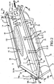
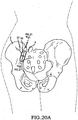
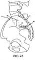
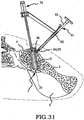
- these procedures typically involve fixation of the sacroiliac joint (immobilization of the articular surfaces of the sacroiliac joint in relation to one another) by placement of one or more screws or by placement of one or more trans-sacroiliac implants (as shown by the non-limiting example of Figure 1 ) or by placement of implants into the S1 pedicle and iliac bone.
- Use of trans-sacroiliac and S1 pedicle-iliac bone implants can also involve the risk of damage to the lumbosacral neurovascular elements. Damage to the lumbosacral neurovascular elements as well as delayed union or non-union of the sacroiliac joint by use of these procedures may require revision surgery to remove all or a portion of the implants or repeat surgery as to these complications.
- trans-sacroiliac elongate implants which do not include a threaded surface.
- This approach requires the creation of trans-sacroiliac bores in the pelvis and nearby sacral foramen which can be of relatively large dimension and which are subsequently broached with instruments which can result in bone being impacted into the pelvis and neuroforamen.
- trans-sacroiliac bores and subsequent broaching of the bores requires a guide pin which may be inadvertently advanced into the pelvis or sacral foramen resulting in damage to other structures. Additionally, producing the trans-sacroiliac bores, broaching, or placement of the elongate implants may result in damage to the lumbosacral neurovascular elements, as above discussed. Additionally, there may be no actual fusion of the articular portion of the sacroiliac joint which may result in continued or recurrent pain requiring additional surgery.
- Another substantial problem with conventional procedures can be that placement of posterior extra-articular distracting fusion implants and bone grafts as described for example in United States Patent Application No. 10/797,481 of Stark (now US patent application US2008/0009861 ) may be inadequate with respect to removal of the articular surface or preparation of cortical bone, the implant structure and fixation of the sacroiliac joint.
- the method may not remove sufficient amounts of the articular surfaces or cortical surfaces of the sacroiliac joint to relieve pain in the sacroiliac joint.
- the implant structures described may have insufficient or avoid engagement with the articular surfaces or cortical bone of the sacroiliac joint for adequate fixation or fusion.
- the failure to sufficiently stabilize and fuse the sacroiliac joint with the implant structures and methods described by the Stark application may result in a failure to relieve the condition of sacroiliac joint being treated. Additionally, the method of driving apart a sacrum and ilium as described by Stark may lead to mal-alignment of the sacroiliac joint and increased pain.
- US 6,241,771 describes a resorbable interbody fusion device for use in spinal fixation, in the shape of a tapered wedge or cone, which incorporates structural features such as serrations or threads to anchor the device in the adjoining vertebrae.
- US2007/156241 describes bone fixation/fusion devices and related methods for stabilizing bone segments.
- the device includes at least one fixation ridge on the body.
- US 6,723,099 describes a surgical tack for bone fixation having a body portion with barbs on the outside of the body portion to fixedly engage a bone structure, and a head portion to assist in implantation of the surgical tack.
- the tack also includes fins on the body portion to reduce implantation forces while not reducing the holding power of the surgical tack.
- the barbs extend from the fins to engage a bone structure.
- the inventive sacroiliac fusion system described herein addresses the problems associated with conventional methods and apparatuses used in fixation and fusion of the sacroiliac joint.
- a sacroiliac joint implant according to claim 1. Also provided is a system for fixating a sacroiliac joint in accordance with claim 11. Further features of the invention are described in the dependent claims.
- a broad object of the invention can be to provide an inventive sacroiliac joint implant for fixation and fusion of the sacroiliac joint.
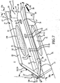
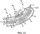
- Embodiments of the sacroiliac joint implant provide an elongate body, which further include a pair of members which extend distance radially outward from the longitudinal axis of the elongate body adapted for non-transverse placement between the articular surfaces of the sacroiliac joint and further provide a third radial member and additionally a fourth radial member each adapted to extend a distance radially outward from the longitudinal axis of the elongate body into the bone of the sacrum or the ilium.
- Also described herein is a method for fixation and fusion of the sacroiliac joint which utilizes the inventive sacroiliac implant.
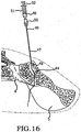
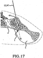
- the method comprising the steps of performing a minimally invasive posterior surgery that allows access to the posterior aspect of the sacroiliac joint for removing a sufficient portion of the articular cartilage or tissue between the articular surfaces of the sacroiliac joint which can be replaced by embodiments of the above described sacroiliac implant.
- a portion of the subcondral bone of the sacroiliac joint can be removed to provide an implant receiving space in the plane of the sacroiliac joint (non-trans-sacroiliac) configured to allow interference fitting of the elongate member, or the elongate member with at least a first radial member between the opposed surfaces of the implant receiving space.
- the method can further include the step of providing the implant receiving space with one or more radial member receiving channels cut into the bone (including one or more of the subchondral, cortical, or cancellous) and thereby locating one or more radial members in the bone of the sacrum or the bone of the ilium.
- the method avoids conventional trans-sacroiliac placement of fixation elements or S1 pedicle and intrailiac screws joined by a rod while providing immediate fixation of the sacroiliac joint.
- bone ingrowth aperture elements which communicate between the opposed surfaces of one or more radial members or through the generally linear elongate body each having a configuration which allows the bone of the sacrum and ilium to grow into or through the implant to facilitate fusion of the sacrum to the ilium and fixation of the sacroiliac joint.
- fixation fusion implant with an amount of curvature along the length of the implant which allows placement of embodiments of the fixation fusion implant which have an increased surface area which remain within or substantially within the articular portion of the sacroiliac joint.
- a sacroiliac joint fixation fusion system that provides a method of fixation and fusion of the sacroiliac joint and a sacroiliac joint implant which upon placement within the articular region of the sacroiliac joint facilitates stability and fusion of the sacroiliac joint.
- Figure 1 shows one commonly utilized conventional method and device for fixation of the sacroiliac joint (1).
- the conventional device shown comprises one or more substantially linear elongate members (2) which can be inserted into correspondingly dimensioned trans-iliac bores (3) with a first portion expending into the bone of sacrum (4) and a second portion extending into the bone of the ilium (5), thereby extending across the sacroiliac joint (1).
- the one or more substantially linear elongate members (2) (which can be configured as cylindrical rods which can further include an amount of taper or further include a spiral thread coupled to the exterior surface to avoid the need for generating trans-iliac bores) in trans-iliac placement can locate the ilium (5) in fixed relation to the sacrum (4).
- this trans-iliac placement of such substantially linear elongate members (2) can have the disadvantages described above.
- conventional placement of the trans-iliac bores (3) and the elongate members (2) can be outside of that region defined by the boundary of the paired articular surfaces (16)(also commonly referred to as the "auricular surfaces") of the sacroiliac joint (1), as further described below.
- an embodiment of an inventive sacroiliac joint implant (6) which in part can include an elongate body (7) which having a longitudinal axis (8).
- the elongate body (7) can have a configuration of sufficient dimension to avoid deformation under the normal forces of surgical placement and fixation of the ilium (5) in relation to the sacrum (4).
- the embodiment of the sacroiliac joint implant (6) shown in Figures 2-6 can be generally cylindrical or circular in cross section; the invention is not so limited, and the elongate body (7) can have any of a numerous arid varied configurations in cross section consistent with the method herein after described such as oval, triangular, rectangular, square, diamond, or the like.
- the generally cylindrical elongate body (7) shown in Figure 2 can depending on the application have a diameter of in the range of about 0.5 centimeters ("cm") to about 1 cm and a length disposed between a first implant end (11) and a second end (12) in the range of about 3 cm and about 6 cm.
- the elongate body (7) can further include an axial bore (9) that bounds an axial pathway (10) which communicates between a first implant end (11) and a second implant end (12) of the elongate body (7).
- the axial bore (9) allows for placement within the axial pathway (10) a guide pin (13) (or other guide member) about which embodiments of the sacroiliac joint implant (6) can be guided for insertion and placement in the sacroiliac joint (1), as further described below.
- embodiments of the sacroiliac joint implant (6) can further include a first radial member (14) coupled to the external surface of the elongate body (7) extending radially outward generally along the longitudinal axis (8).
- the first radial member (14) can extend along the longitudinal axis (8) substantially the entire length of the elongate body (7); however, the invention is not so limited, and embodiments of the inventive sacroiliac joint implant (6) can have a first radial member (14) which can in part or in a plurality of discontinuous parts extend along the longitudinal axis (8) or the elongate body (7).
- embodiments of the sacroiliac joint implant (6) can further include a second radial member (15).
- Each of the first radial member (14) and the second radial member (15) can extend radially outward from the elongate body (7) generally in opposed relation (about 180 degrees apart about the longitudinal axis (8) of the elongate body (7); however, the invention is not so limited, and the first radial member (14) and the second radial member (15) can be spaced about the elongate body (7) a greater or lesser number of degrees.
- each of the first radial member (14) or second radial member (15)(or both) can be adapted to non-transversely locate between the articular surfaces (16) of the sacroiliac joint (1) to dispose the sacrum (4) and the ilium (5) in substantially immobilized, immobilized, or fixed relation.
- non-transversely as used herein means not lying or extended across the joint between the sacrum (4) and the ilium (5) and in particular does not include trans-iliac placement of a sacroiliac joint implant as above described and shown in Figure 1 .
- articular surfaces includes the two paired L-shaped surfaces formed between the surfaces of the sacrum (4) and the ilium (5) having a cranial portion (87) and a caudal portion (86) as shown for example in Figures 25 , 27 , and 29 (broken line) and as used herein does not include structures or regions of the sacrum (4) or the ilium (5) outside of the articular surfaces (16), such as, the paired iliac tuberosity and sacral fossa.
- Each of the first radial member (14) and the second radial member (15) can each provide a pair of opposed faces (17)(18) disposed a thickness (19A) apart and having an area bound by a top edge (20), a pair of side edges (21)(22) and a bottom edge (23).
- the first of the pair of side edges (21) can be connected as above described to the elongate body (7) locating the second side edge (22) a distance outward from the longitudinal axis (8) of the elongate body (7).
- each of the first radial member (14) and the second radial member (15) can be substantially rectangular in configuration having a height (28a) between the first of the pair of side edges (21) and the second of the pair of side edges (22) in the range of about 0.2 cm and about 1 cm.
- a lesser diameter elongate body (7) may include a first radial member (14) and a second radial member (15)(or other radial members) having greater height (28a) and a greater diameter elongate body (7) may require a first radial member (14) and a second radial member (15)(or other radial members) having lesser height (28a).
- each of the first radial member (14) and the second radial member (15) can terminate substantially in alignment with the first implant end (11) of the elongate body (7).
- the bottom edge (23) of the first radial member (14) and the second radial member (15) can terminate substantially in alignment with second implant end (12) of the elongate body (7).
- the bottom edge (23) can further include an angle element (24) which angles outward from the elongate body (7) commencing at the second implant end (12) and joining the second of pair of side edges (22) a distance toward the first implant end (11).
- the angle element (24) can have a degree angle (25) from the perpendicular with the longitudinal axis (8) in a range of about fifteen degrees to about thirty degrees, as shown in Figure 2 ; however, the invention is not so limited and the angle element (24) can be a radius element, tapered element or other element to ease insertion into the sacroiliac joint (1).
- certain embodiments of the sacroiliac joint implant (6) can further include a third radial member (26) extending along the longitudinal axis (8) of said elongate body (7) adapted to extend into the cortical bone of the ilium (5). Certain embodiments can further include a fourth radial member (27) extending along the longitudinal axis (8) of said elongate body (7) adapted to extend into the cortical bone of said sacrum (4). Certain embodiments of the third radial member (26) and the fourth radial member (27) can be adapted to extend into the bone of the sacrum (4) and the ilium (5) respectively.
- the third radial member (26) and the fourth radial member (27) can be connected generally in line with the longitudinal axis (8) of the elongate body (7).
- Each of the third radial member (26) and the fourth radial member (27) can extend radially outward from the elongate body (7) substantially in opposed relation (about 180 degrees apart) and in perpendicular relation (about 90 degrees) to the first radial member (14) and the second radial member (15)(see also Figures 8 and 9C ); however, the invention is not so limited, and the third radial member (26) and the fourth radial member (27)(if the embodiment includes a fourth radial member (27)) can be spaced about the elongate body (7) in relation to each other and in relation to the first radial member (14) and the second radial member (15) a greater or lesser number of degrees depending on the application and the amount of desired engagement with the bone of the sacrum (4) or ilium (5).
- each of the third radial member (26) or the fourth radial member (27) can vary as necessary to provide an amount of surface area engagable with the bone of the sacrum (4) and ilium (5) sufficient for facilitating substantial immobilization, immobilization, or to fix, the sacrum (4) in relation to the ilium (5) upon implantation of the sacroiliac joint implant (6) and to further provide a resistance to rotation or other undesired movement of the sacroiliac joint implant (6) at the implant location within the region bounded by the articulating surfaces (16) of the sacroiliac joint (1).
- embodiments of the sacroiliac joint implant (6) having a third radial member (26) and the fourth radial member (27) can provide a pair of opposed faces (17)(18) disposed a thickness (19b) apart and have an area bound by a top edge (20), a pair of side edges (21) (22) and a bottom edge (23) in similar configuration as above described for the first radial member (14) and the second radial member (15).
- the first of the pair of side edges (21) can be connected as above described to the elongate body (7) locating the second side edge (22) a distance outward from the longitudinal axis (8) of the elongate body (7).
- each of the third radial member (26) and the fourth radial member (27) can have a substantially rectangular configuration having a height (28b) between the first of the pair of side edges (21) and the second of the pair of side edges (22) in the range of about 0.1 cm and about 0.4 cm.
- the top edge (20) of each of the third radial member (26) and the fourth radial member (27) can terminate substantially in alignment with the first implant end (11) of the elongate body (7).
- the bottom edge (23) of the third radial member (26) and the fourth radial member (27) can terminate substantially in alignment with second implant end (12) of the elongate body (7).
- the bottom edge (23) of the third radial member (26) and the fourth radial member (27) can further include the angle element (24) which angles the second of the pair of side edges (22) toward the first implant end (11) of the elongate body (7).
- the angle element (24) can have a degree angle (25) from the perpendicular with the longitudinal axis (8) in a range of about fifteen degrees to about thirty degrees; however, the invention is not so limited and with respect to certain embodiments of the invention there may be no angle element (24) or the angle element may be greater or less than within the range of about fifteen degrees to about thirty degrees.
- the angle element (24) can be similar as shown in the figures or can be dissimilar between the radial members of a particular sacroiliac joint implant (6) depending on the application.
- the third radial member (26) and the fourth radial member (27) can have a lesser height (28b) than the first radial member (14) and second radial member (15). While the structure of the third radial member (26) and the fourth radial member (27) appear similar to the first radial member (14) and the second radial member (15), the function can be substantially different.
- the first radial member (14) and the second radial member (15) have a configuration (height, length, thickness, surface area, and location in relation to the external surface of the elongate body (7), as above described) capable of or allowing placement non-transversely between he articular surfaces (16) (and not across) or within an implant receiving space (29) surgically produced within the region bounded by the articular surfaces (16) by removal of a portion the sacroiliac joint (1), as further described below, capable upon placement between the articular surfaces (16) or within the implant receiving space (29) of substantially immobilizing or immobilizing the sacroiliac joint (1).
- the third radial member (26), and as to those embodiments having a fourth radial member (27), can have a configuration (height, length, thickness, surface area, and location on the external surface of the elongate body (7), as above described) capable of being forcibly urged a depth into the cortical bone or the cancellous bone of the sacrum (4) or the ilium (5) or placed within the radial member receiving channel (74) of the implant receiving space (29) upon non-transversely locating the sacroiliac joint implant (6) between the articular surfaces (16) of the sacroiliac joint (1).
- each radial member (14)(15)(26)(27) extending outwardly from the elongate body (7) can terminate in a radial member cross piece (98) disposed in substantially perpendicular relation to the surfaces of the radial member.
- particular embodiments of the sacroiliac joint implant (6) can further include one or more aperture elements (31) which communicates between the opposed faces (17)(18) of the first radial member (14) or the second radial member (15) or both.
- the amount of open space of an aperture element (31) can be defined by an aperture perimeter (32) which can be of numerous and varied configurations of sufficient dimension to allow the surfaces of the ilium (5) or sacrum (4)(or both) adjacent to the first radial member (14) or the second radial member (15)(or both) of the sacroiliac joint implant (6) to grow a distance into the aperture element (31) or through the aperture element (31) or fuse within the aperture element (31) or fuse into material placed within the aperture element, the material can include: osseointegratable, osteoinductive, osteoconductive, osteogenic materials or biologically active agents, or combinations and permutation thereof.
- the aperture perimeter (32) can be of generally oval configuration resulting in an oval aperture element (31) located in the first radial member (14) or the second radial member (15)(or both)(or located in additional radial members depending upon the embodiment) with the length of the oval aperture element (31) aligned with the length of the first radial member (14) or second radial member (15) and being about one quarter to about two thirds the length of the radial member and having a width of the oval aperture element (31) located between the sides (21)(22) of the first radial member (14) or second radial member (15) and being about one quarter to about two thirds the height (28a).
- the elongate body (7) can further include aperture elements (31) which communicate between the external surfaces between the radial members (14)(15)(26)(27).
- embodiments of the sacroiliac joint implant (6) can further include an anti-migration element (33) coupled to the first implant end (11) of the elongate body (7).
- the anti-migration element (33) can take the form of an enlarged terminal portion of the first end of the elongate body (7)(as shown in Figures 2-6 ), an increase in the height (28) of one or more of the radial members (such as flaring outward as shown in Figure 7 ) proximate the first implant end (11) of the elongate body (7).
- the anti-migration element (33) can take the form of an end cap (34) having a generally circular configuration with the center substantially aligned with the longitudinal axis (8) of the elongate member (7) and extending radially outward sufficient distance to prevent advancement of the second implant end (12) of the sacroiliac joint implant (6) further into the sacroiliac joint (1) subsequent to implantation in the implant receiving space (29). While the end cap (34) shown is generally circular in configuration, the end cap (34) can have end cap perimeter (35) which defines an oval, square, rectangle, or other configuration useful in fixing the location of the sacroiliac joint implant (6) in relation the sacroiliac joint (1).
- the anti-migration element (33) can have sufficient dimensions to further include one or more bores (36) which communicate between the opposed surfaces (37)(38) of the anti-migration element (33) and dimensioned to receive mechanical fasteners (39)(such threaded members, barbed members, locking members or the like) which can be driven or rotated to engage a portion of the mechanical fastener with the sacrum (4) or the ilium (5).
- the anti-migration element (33) can also take the form of tapered elements on a part or the entirety of the external surface which taper outward from the surface allowing insertion of embodiments of the sacroiliac joint implant (6) but opposes backward travel.
- the anti-migration element (33) can take the form of tapered terminal end (33/99) of the sacroiliac joint implant (6) which resists forward or backward travel of the sacroiliac joint implant (6).
- the elongate body (7) along with the other elements of the sacroiliac joint implant (6) above described can be fabricated or formed from a plurality of pieces or as a single piece of biocompatible material or a combination of biocompatible and biodegradable materials of suitably dimensioned particles, sheets, or other constructional forms or formable or moldable materials suitably bound or formed or molded to provide configurations in accordance with the invention.
- embodiments of the sacroiliac joint implant (6) can further include a coat (40) coupled, generated or integral to all or a part of the external surface of the sacroiliac joint implant (6).
- the coat (40) can be of any composition that can be coupled to the sacroiliac joint implant (6) capable of biocompatible osseointegration with the bone of the ilium (5) and sacrum (4), such as pure alumina, titanium-dioxide, hydroxyapatite, calcium triphosphate, or the like.
- the coat (40) can be applied by plasma spraying with a plasma torch, plasmatron or a plasma gun.
- the coat (40) can be achieved by producing a surface roughness, porosity, or irregularity of the sacroiliac joint implant (6) by sand blasting, bead blasting, molding, or the like.
- the coat (40) can have a thickness in the range of about 40 ⁇ m and about 100 ⁇ m.
- embodiments of the sacroiliac joint implant (6) can be configured as a material having interconnecting pores throughout such as TRABECULAR METAL available from Zimmer, P.O. Box 708, 1800 West Center Street, Warsaw, Indiana 46581-0708 or a metallic foam such as a titanium foam available from the National Research Council Canada, 1200 Montreal Road, Bldg. M-58, Ottawa, Ontario, Canada or fully-engineered, porous, titanium structures such as TRABECULITE available from Tecomet, 115 Eames Street, Wilmington, MA 018877.
- embodiments of the invention can further include one or more biologically active agent(s) (41) which can be applied directly to the external surface of the sacroiliac joint implant (6) or can be mixed with a biocompatible material or biocompatible biodegradable material or biocompatible osseointegratable material (collectively numeric indicator (100) which can be applied to the external surface of the sacroiliac joint implant (6) or otherwise made a part of the sacroiliac joint implant (6).
- biologically active agent(s) (41) which can be applied directly to the external surface of the sacroiliac joint implant (6) or can be mixed with a biocompatible material or biocompatible biodegradable material or biocompatible osseointegratable material (collectively numeric indicator (100) which can be applied to the external surface of the sacroiliac joint implant (6) or otherwise made a part of the sacroiliac joint implant (6).
- the biologically active agent(s)(41) can be mixed with an amount of a biocompatible biodegradable material or osseointegrateable material (100) and located within one or more of the aperture elements (31).
- Biocompatible for the purposes of this invention means the ability of any material to perform the intended function of an embodiment of the invention without eliciting any undesirable local or systemic effects on the recipient and can include non-biodegradable materials such as: ceramic; metals or steels such as titanium alloys or rigid polymeric materials or rigid laminate materials or composites which include suitably dimensioned particles of metals or steels dispersed within rigid laminate materials, or suitably sized particles of biocompatible materials suitably bound or formed to provide configurations, polyurethanes, polyisobutylene, ethylene-alpha-olefin copolymers, acrylic polymers and copolymers, vinyl halide polymers and copolymers, polyvinyl esters, polyvinylidene chloride, polyacrylonitrile, polyvinyl ketones, polyvinyl aromatics such as polystyrene, copolymers of vinyl monomers and olefins such as ethylene-methyl methacrylate copolymers, acrylonitrile-styrene
- Biodegradable for the purposes of this invention means the ability of any biocompatible material to breakdown within the physiological environment of the sacroiliac joint by one or more physical, chemical, or cellular processes at a rate consistent with providing treatment of a condition of the sacroiliac joint at a therapeutic level controllable by selection of a polymer or mixture of polymers (also referred to as polymeric materials), including, but not limited to: polylactide polymers (PLA), copolymers of lactic and glycolic acids (PLGA), polylactic acid-polyethylene oxide copolymers, poly( ⁇ -caprolactone-co-L-lactic acid (PCL-LA), glycine/PLA copolymers, PLA copolymers involving polyethylene oxides (PEO), acetylated polyvinyl alcohol (PVA)/polycaprolactone copolymers, hydroxybutyrate-hydroxyvalerate copolymers, polyesters such as, but not limited to, aspartic acid and different aliphatic dio
- Bioly active agents for the purposes of this invention means those agents or mixture of agents which can be varied in kind or amount to provide a therapeutic level effective to mediate the formation or healing of bone, cartilage, tendon, or to reduce, inhibit, or prevent a symptom of a condition of the sacroiliac joint subsequent to placement of an embodiment of the fixation fusion implant within the sacroiliac joint (1) such as infection or pain and without limitation can include agents that influence the growth of bone, demineralized bone matrix, stem cells, alleografts, autografts, xenografts, bone forming protein whether naturally occurring, synthetic, or recombinate, growth factors, cytokines, bone morphogenetic protein 2, bone morphogenetic protein 7, analgesics, anesthetics, anti-inflammatory agents, antibacterials, antivirals, antifungals, antiprotozoals, anti-infectives, antibiotics such as aminoglycosides such as gentamicin, kanamycin, neomycin, and
- the biologically active agent(s)(41) can be dispersed throughout a biocompatible or biocompatible biodegradable material (or mixture of biocompatible materials or mixture of biocompatible biodegradable materials) by mixing biologically active agent(s)(41) into the melted biocompatible or biodegradable polymer and then solidifying the resulting material by cooling, having the biologically active agent(s)(41) substantially uniformly dispersed throughout.
- the biodegradable material or biocompatible material or mixture thereof can be selected to have a melting point that is below the temperature at which the biologically active agent(s)(41) becomes reactive or degrades.
- the biologically active agent(s)(41) can be dispersed throughout the biocompatible or biodegradable material by solvent casting, in which the biocompatible or biodegradable material is dissolved in a solvent, and the biologically active agent(s)(41) dissolved or dispersed in the solution. The solvent is then evaporated, leaving the biologically active agent(s)(41) in the matrix of the biocompatible or biodegradable material. Solvent casting requires that the biocompatible or biodegradable material be soluble in organic solvents.
- the fixation fusion implant (6) can be placed in a solvent having a concentration of the biologically active agent(s)(41) dissolved and in which the fixation fusion implant (6) or the biocompatible or biocompatible biodegradable material located in the aperture elements, or applied to the external surface, swells. Swelling of the fixation fusion implant (6) or portions thereof draws in an amount of the biologically active agent(s) (41). The solvent can then be evaporated leaving the biologically active agent(s)(41) within the biocompatible or biocompatible biodegradable material.
- therapeutic levels of biologically active agent(s)(41) can be included in biocompatible biodegradable material to provide therapeutically effective levels of the biologically active agent to the sacroiliac joint (1) to treat a particular sacroiliac joint condition.
- non-active agents (42) may be included in the biocompatible biodegradable material for a variety of purposes.
- buffering agents and preservatives may be employed.
- Preservatives which may be used include, but are not limited to, sodium bisulfite, sodium bisulfate, sodium thiosulfate, benzalkonium chloride, chlorobutanol, thimerosal, phenylmercuric acetate, phenylmercuric nitrate, methylparaben, polyvinyl alcohol and phenylethyl alcohol.
- buffering agents examples include, but are not limited to, sodium carbonate, sodium borate, sodium phosphate, sodium acetate, sodium bicarbonate, and the like, as approved by the FDA or other appropriate agencies in the United States or foreign countries, for the desired route of administration. Electrolytes such as sodium chloride and potassium chloride may also be included in the formulation.
- embodiments of the fixation fusion implant (6) having a biocompatible biodegradable portion with biologically active agent(s)(41) for treating the sacroiliac joint (1) can be made by dispersing a biologically active agent(s)(41) in a biocompatible biodegradable material as above described to provide biologically active agent(s) (41) release characteristics at a therapeutic level.
- the biocompatible biodegradable portion of the fixation fusion implant (6) can substantially continuously release biologically active agent (41) to provide a localized amount of bone morphogenetic protein 2 at therapeutic levels of about 1 milligram to about 4 milligrams to facilitate bone regrowth.
- fixation fusion implant (6) which delivers an amount of bone morphogenetic protein 2 to facilitate bone regrowth
- embodiments of the fixation fusion implant (6) can be utilized to deliver numerous and varied active agent(s)(41) individually or in combination to treat a wide range of conditions of the sacroiliac joint (1) subsequent to implantation of embodiments of the fixation fusion implant (6).
- particular embodiments of the invention can further include an amount of curvature (43) between the first implant end (11) and the second implant end (12) of the fixation fusion implant (6).
- the amount of curvature (43) can vary from embodiment to embodiment of the fixation fusion implant (6) depending on the application between a substantially linear elongate body (7) as above described to including an amount of curvature (43) which defines a radius to facilitate placement in the cranial portion (87) and a caudal portion (86) between the articular surfaces (16) of the sacroiliac joint (1) or in the corresponding implant receiving space (29).
- the radius can be within a range of about 2 cm and about 6 cm.
- certain embodiments of the invention having an amount of curvature can be provided in a plurality of implant segments (101)(102)(103) which can be individually implanted within the articular region (44) as shown in Figure 25 , 27 , or 29 by the method below described.
- embodiments of the sacroiliac joint implant (6) can be configured to house a bone growth simulator (105).
- Useful implantable growth stimulators can directly engage the anode of a battery and a single or double titanium cathode wire implanted within or in close proximity to the sacroiliac joint implant (6).
- the cathode wire can be disposed a distance into the host bone, bone graft, or portions of the device, preferably with the cathode ends contacting and or anchored into living bone.
- Embodiments of the invention can include a metal implant with an insulation material, such as PEEK, to prevent cathode-metal contact, while permitting cathode-bone contact.
- the battery can be placed in an extrafascial, subcutaneous pocket for removable placement.
- a suitable growth stimulator is available from Biomet Trauma 100 Interpace Pkwy # 1, Parsippany, NJ 07054-1149.
- a plurality of inventive sacroiliac joint implants (6) whether separately or in joined relation, whether the same or different embodiments, can be utilized with conventional or the inventive methods of implantation herein described for fixation and fusion of the sacroiliac joint (1).
- a plurality of elongate bodies (7) can be joined in fixed, substantially fixed or movable relation to provide an embodiment of the sacroiliac joint implant (6).
- FIG. 16-24 a non-limiting method of accessing an articular region (44) between the articulating surfaces (16) of the sacroiliac joint (1) and placing a sacroiliac joint implant (6) non-transversely between the articulating surfaces (16) within the articular region (44) of the sacroiliac joint (1) to dispose the sacrum (4) and the ilium (5) in substantially immobilized relation by corresponding engagement of the sacroiliac joint implant (6) by the articulating surfaces (16) of the sacroiliac joint (1).
- an embodiment of the method can include the step of placing a patient under sedation prone on a translucent operating table (or other suitable surface).
- the sacroiliac joint (1) can be locally anesthetized to allow for injecting a radiographic contrast (46) (as a non-limiting example, Isoview 300 radiographic contrast) under fluoroscopic guidance into the inferior aspect of the sacroiliac joint (1) to outline the articular surfaces (16) of the sacroiliac joint (1).
- a radiographic contrast as a non-limiting example, Isoview 300 radiographic contrast
- Injection of the radiographic contrast (46) within the sacroiliac joint (1) can be accomplished utilizing a tubular member (47)(such as a syringe needle) having first tubular member end (48) which can be advanced between the articulating surfaces (16) of the sacroiliac joint (1) and having a second tubular member end (49) which removably couples to a hub (50).
- the hub (50) can be configured to removably couple to a syringe barrel (51)(or other device to contain and deliver an amount of radiographic contrast (46)).
- the syringe barrel (51) can have an internal volume capable of receiving an amount of the radiographic contrast (46) sufficient for outlining the lateral articular surfaces (16) of the sacroiliac joint (1).
- a plunger (52) can be slidingly received within the barrel (51) to deliver the radiographic contrast (46) through the tubular member (47) into the sacroiliac joint (1).
- the tubular member (47) can have a gauge in the range of about 16 gauge and about 20 gauge and can further be incrementally marked on the external surface to allow determination of the depth at which the first needle end (48) has advanced within the sacroiliac joint (1).
- the radiographic dye (46) can be delivered from within the syringe barrel (51) into the sacroiliac joint (1) to allow visualization of the sacroiliac joint (1) and location of the tubular needle (47) within the sacroiliac joint (1).
- the hub (50) can be removed from the tubular member (47) leaving the tubular member (47) fixed within the sacroiliac joint (1) as a initial guide for tools subsequently used to locate or place the sacroiliac joint implant (6) non-transversely between the articulating surfaces (16) of the sacroiliac joint (1) or in removal of a portion of the sacroiliac joint (1) within the region defined by the articular surfaces (16) to generate an implant receiving space (29).
- one or more guide pins (13) can be inserted along substantially the same path of the tubular member (47) for fixed engagement within the sacroiliac joint (1) and used in subsequent steps as a guide(s).
- a small incision can be made in the skin at the posterior superior (or as to certain embodiments inferior) aspect of the sacroiliac joint (1), extending proximal and distal to the tubular member (47) along the line of the sacroiliac joint (1) to provide a passage to access the interarticular space between the articulating surfaces (16) of the sacroiliac joint (1).
- a cannulated probe (53) can be slidingly engaged with the tubular member (47)(or guide pin (13)) extending outwardly from the sacroiliac joint (1) (while the sacroiliac joint may be shown in the figures as being substantially linear for illustrative purposes, it is to be understood that the normal irregular features of the sacroiliac joint have not been removed).
- the cannulated probe (53) can have a probe body (54) of generally cylindrical shape terminating in a spatulate tip (55) at the end advanced into the sacroiliac joint (1).
- a removable cannulated probe handle (56) couples to the opposed end of the probe body (54).
- the spatulate tip (55) can be guided along the tubular needle (47)(or guide wire (13) into the posterior portion of the sacroiliac joint (1) and advanced to the anterior portion of the sacroiliac joint (1) under lateral fluoroscopic visualization.
- the cannulated probe handle (56) can then be removed providing the generally cylindrical probe body (54) extending outwardly from the sacroiliac joint (1) through the incision made in the skin.
- a passage from the incision to the sacroiliac joint (1) can be generated by inserting a cannula (57) into the incision.
- a soft tissue dilator (58) having a blunt end (59) can be advanced over the probe body (54), or a plurality of soft tissue dilators of increasing size, until the blunt end (59) of the soft tissue dilator (58) and the corresponding cannula end (45) contact the posterior aspect of the sacroiliac joint (1).
- the soft tissue dilator (58) can be removed from within the cannula (57).
- the external surface of the cannula (57) can be sufficiently engaged with the surrounding tissue to avoid having the tissue locate with in the hollow inside of the cannula (57).
- a non-limiting embodiment of the cannula (57) provides a tubular body having substantially parallel opposed side walls which terminate in a radius at both ends (lozenge shape) into which a plurality of different jigs can be inserted.
- a cannula alignment jig (60) can be advanced over the probe body (54)(or guide pins (13)) and received within the cannula (57).
- Substantially, identical cross hairs (63)(64) can be disposed on the upper jig surface (65) and the lower jig surface (66). Alignment of the cross hairs (63)(64) under x-ray with the sacroiliac joint (1) can confirm that the cannula (57) has proper orientation in relation to the paired articular surfaces (16) of the sacroiliac joint (1).
- the cannula (57) properly oriented with the paired articular surfaces (16) can than be disposed in fixed relation to the sacroiliac joint by placement of fasteners through the cannula (57) into the sacrum (4) or the ilium (5).
- a first drill jig (67) can be advanced over the probe body (54)(or guide pins (13) and received within the cannula (57).
- the probe body (54)(or guide pins (13)) extending outwardly from the sacroiliac joint (1) passes through a drill guide hole (68) of the first drill jig (67)(or a plurality of guide pins (13) can extend through a corresponding plurality of guide pin holes (69)).
- the drill guide hole (68) can take the form of a circular hole as shown in the Figures, a slot, or other configuration to restrict the movement of the drill bit (62) within the drill jig (60) and provide a guide for a drill bit (62) in relation to the sacroiliac joint (1).
- a cannulated drill bit (70) can be advanced over the probe body (54) and within a drill guide hole (68) of the first drill jig (67).
- the cannulated drill bit (70) under fluoroscopic guidance can be advanced into the interarticular region (44) between the articulating surfaces (16) of the sacroiliac joint (1) to produce a first bore (71)(shown in broken line) to a determined depth.
- an amount of articular cartilage or other tissues from between the articular surfaces (16) of the sacroiliac joint (1) can be removed sufficient to allow embodiments of the sacroiliac joint implant (6) to be implanted in replacement of the removed articular cartilage or tissue.
- the method removes the degenerative articular cartilage or tissue between the articular surfaces (16) of the sacroiliac joint (1)
- the articular surfaces (16) of the sacroiliac joint (1) can remain intact or substantially intact allowing the sacroiliac joint implant (6) to be non-transverely located between the articular surfaces (16) of the sacroiliac joint (1).
- a cannulated drill bit (62) for the removal of articular cartilage or tissue between articular surfaces (16) such as: box chisels, burs, hole saws, curettes, lasers (such as CO2, Neodymium/YAG (yttrium-aluminum-garnet), argon, and ruby), electrosurgical equipment employing electromagnetic energy (the cutting electrode can be a fine micro-needle, a lancet, a knife, a wire or band loop, a snare, an energized scalpel, or the like) where the energy transmitted can be either monopolar or bipolar and operate with high frequency currents, for example, in the range of about 300kHz and about 1000 kHz whether as pure sinusoidal current waveform where the "crest factor" can be constant at about 1.4 for every sinus waveform, and a voltage peak of approximately 300 V to enable a "pure” cutting effect with the smallest possible coagulation effect or as amplitude modulated current wave
- the cutting electrode can be a fine micro-
- Electrosurgical waveforms may be set to promote two types of tissue effects, namely coagulation (temperature rises within cells, which then dehydrate and shrink) or cut (heating of cellular water occurs so rapidly that cells burst).
- the proportion of cells coagulated to those cut can be varied, resulting in a "blended” or “mixed” effect.
- a fully rectified current, or a partially rectified current, or a fulguration current where a greater amount or lateral heat is produced can be employed to find the articular surfaces of the joint and aid in advancing a probe or guide wire into a position in between the articulating surfaces. These currents can effectively degrade the cartilage and allow advance into the joint without grossly penetrating much beyond the cartilage.
- the first drill jig (67) can be removed from within the cannula (57) and a second drill jig (72) can be advanced over the probe body (54) and received within the cannula (57); however, the invention is not limited to any particular number of drill jigs and as to certain embodiments of the method the first drill jig (67) can include all the required drill guide hole(s) (68)(or slots or other configurations of the drill guide) and as to other embodiments of the method a plurality of drill jigs can be utilized in serial order to provide all the drill guide holes (68).
- the first drill jig (67) can provide one or more additional drill guide holes (68) which guide in relation to the first bore (71) a second or more cannulated drills (62) of the same or different configuration to be inserted within and advanced into the sacroiliac joint (1) to produce a second bore (73)(generally shown in broken line as 71/73) or a plurality of bores within the sacroiliac joint (1) spaced apart in predetermined pattern to allow removal of sufficient articular cartilage (16) or other tissue from the interarticular space of sacroiliac joint (1) for placement of embodiments of the sacroiliac joint implant (6) within the region defined by and between the paired articular surfaces (16) of the sacroiliac joint (1).
- the first drill jig (67) or the second drill jig (72) or a plurality of drill jigs can be utilized in serial order to remove a portion of the sacroiliac joint (1) for generation of an implant receiving space (29).
- articular cartilage or other tissues and sufficient subchondral bone can be removed from between the articular surfaces (16) of the sacroiliac joint (1) sufficient to allow placement of certain embodiments of the sacroiliac joint implant (6) and one or more radial member receiving channels (74) can be cut into at least one of the articular surfaces (16) of said sacroiliac joint (1) sufficient to receive other embodiments of the sacroiliac implant (6).
- the one or more radial member receiving channels (74) can be cut a depth into the subchondral, cortical bone or cancellous bone of the sacrum (4) or ilium (5).
- the last in the serial presentation of drill jigs (67)(72) can be removed from within the cannula (57) and a broach jig (75) can be advanced over the probe body (54) to locate within the cannula (57).
- the broach jig (75) can include a broach guide hole (76) which receives a first broach end (77) of a cannulated broach (78) advanced over the probe body (54).
- the first broach end (77) can have a configuration which can be advanced into the sacroiliac joint (1).
- the first broach end (77) can be adapted to remove an amount of articular cartilage and other tissue from the betweent the articular surfaces (16) within th articular region (44) of the sacroiliac joint (1) for non-transverse placement of a sacroiliac joint implant (6) having an elongate body (7), or having an elongate body (7) and a first radial member (14), or an elongate body (7) having a first and second radial members (14)(15) between the articular surfaces (16) of the sacroiliac joint (1).
- the cannulated broach (78) can remove a sufficient a portion of the sacroiliac joint (1) to generate an implant receiving space (29) to receive embodiments of the sacroiliac joint implant (6) having an elongate body (7), an elongate body (7) and at least one radial member (14) adapted for non-transverse placement between the articular surfaces (16) or at least one radial member (26) adapted to extend into the bone of the sacrum (4) or the ilium (5).
- Figure 24 shows a broach (78) configured to remove a portion of the sacroiliac joint (1) to produce a implant receiving space (29) to receive embodiments of the sacroiliac joint implant (6) having and elongate body (7) to which a first radial member (14) and a second radial member (15) extend along the longitudinal axis (8) of the elongate body (7) in substantially opposed relation adapted to locate between the articular surfaces (16) of the sacroiliac joint (1) and further having a third radial member (26) and a fourth radial member (27) which extend along the longitudinal axis (8) of the elongate member (7) in substantially opposed relation adapted to correspondingly extend correspondingly into the bone of the sacrum (4) and the ilium (5).
- a broach 78 configured to remove a portion of the sacroiliac joint (1) to produce a implant receiving space (29) to receive embodiments of the sacroiliac joint implant (6) having and elongate body
- the implant receiving space (29) and the sacroiliac joint implant (6) can be configured having related dimension relations such that placement of the sacroiliac joint implant (6) within the implant receiving space (29) disposes the sacrum (4) and the ilium (5) in substantially immobilized relation and substantially avoids alteration of the positional relation of the sacrum (4) and the ilium (5) from the normal condition, or avoids driving together or driving apart the sacrum (4) from the ilium (5) outside of or substantially outside of the normal positional relation.
- configurations of an implant receiving space (29) allow embodiments of the sacroiliac joint implant (6) to be placed non-transversely between the caudal portion (86) of the articular surfaces (16) of the sacroiliac joint (1).
- the sacroiliac joint implant (6) may only provide an elongate body (7) which locates within a correspondingly configured implant receiving space (29) to engage at least a portion of the bone of the ilium (5); the invention is not so limited, and can further include at least a first radial member or a first and a second radial member at least a portion of the external surface of the first radial member (14) engaging a portion of the bone (73) of the sacrum (4) and the ilium (5).
- the implant receiving space (29) an further include one more radial member receiving channels (74)) which correspondingly allow the third and fourth radial members (26)(27) to extend into the bone of the sacrum (4) or the ilium (5)(whether subchondral, cortical, cancellous, or the like), or impact of the sacroiliac joint implant (6) into the implant receiving space (29) without the radial member receiving channels (74) can forcibly urge the radial members (26)(27) into the bone of the sacrum (4) and the ilium (5).
- Mechanical fasteners (39) (such as treaded members) can be inserted through the bores (36) in the anti-migration element (33) and into the sacrum (4) and ilium (5) to fix location of the fixation fusion implant (6) within the implant receiving space (29).
- configurations of an implant receiving space (29) allow embodiments of the sacroiliac joint implant (6) to be placed non-transversely between the cranial portion (86) of the articular surfaces (16) of the sacroiliac joint (1) by the similar procedures or steps as above described with the incision and generation of the passage to the superior articular portion of the sacroiliac joint (1).
- configurations of an implant receiving space (29) allow embodiments of the sacroiliac joint implant (6) to be placed non-transversely between the cranial portion (87) and caudal portion (86) of the articular surfaces (16) of the sacroiliac joint (1) by the similar procedures or steps as above described with the incision and generation of the passage to the inferior articular portion of the joint.
- FIG 31 shows an embodiment of the sacroiliac joint implant (6) having a portion of the axial bore (9) adapted to fixedly mate with a portion of an alignment tool (79).
- the alignment tool (79) can have a fixed or adjustably fixed configuration which aligns a cannulated alignment guide (80) with one of the bores (36) through the sacroiliac joint implant (6).
- An insertion tool (81) can be slidingly engaged with the cannulated alignment guide (80).
- An elongate member (85) can be removably fixedly attached to the first insertion tool end (82) proximate the bore (36) in the sacroiliac joint implant (6).
- the second insertion tool end (83) can be forcibly advanced in the cannulated alignment guide (80) to advance the elongate member (81) to pass through the ore (36) to dispose the elongate member (81) in transverse relation to said articular surfaces (16) correspondingly engaged with sacroiliac joint implant (6).
- the elongate member (81) can have a spiral thread (84) coupled to the external surface and by rotation of the second end (83) of the insertion tool (81) the elongate member (85) can be drawn through the bore (36) of the sacroiliac joint implant (1) in transverse relation to said articular surfaces (16) correspondingly engaged with sacroiliac joint implant (6).
- the articular surfaces (16) of the sacroiliac joint (1) can be drawn against the external surfaces of the sacroiliac joint implant (6).
- embodiments of the invention can further comprise a coupling element (87) connected to the first end (11) of the sacroiliac joint implant (6).
- the coupling element (87) can be disposed in fixed relation to the first end (11) of the sacroiliac joint implant (6) by threaded engagement of a fastener portion (88); however, the invention is not so limited and the fastener portion (88) can be connected to the first end (11) of the sacroiliac joint implant (6) by any method such as welding, spin welding, adhesive, or the like.
- the coupling element (87) can further provide a coupling portion (89) configured to join with a numerous and wide variety of cross sectional geometries of spanning members (90).
- the coupling portion (89) can be configured as cylindrical cup (91) pivotally coupled to the fastener portion (88).
- a spiral thread can be coupled to the internal surface of the cylindrical cup (91) to rotationally receive a spirally threaded body (92).
- the side wall (93) of the cylindrical cup (91) can include a pass through element (94) in which part of a spanning member (90) can be received.
- the part of the spanning member (90) received within the pass through element (94) can be placed in fixed relation to the cylindrical cup (91) by rotational engagement of the spirally threaded body (92).
- each of a pair of sacroiliac joints (1) can receive an embodiment of the sacroiliac joint implants (6), above-described, each having a coupling element (87) coupled to the first end (11).
- Each of the coupling elements (87) can receive the opposed ends (95) of a spanning member (90).
- the spanning member (90) in fixed relation to the sacroiliac joint implants (6) can be connected to a plurality of additional spanning members (96) which can as a non-limiting example be placed in positional relation to the vertebral column (97) to allow support of additional implants which can be anchored between vertebrae.
- a first coupling element (87) can be joined to the first end (11) of an embodiment of a sacroiliac joint implant (6) as above described and the fastener portion (88) of a second coupling element (87) can be disposed directly into the bone of the sacrum (4) or the ilium (5), or both.
- the opposed ends (95) of a spanning element (90) in the form of a flat plate can be can provide apertures (96) through which the fastener portion (88) of the coupling element (87) can pass.
- the corresponding parts of the external surface of the coupling portion (89) and the spanning member (90) can be engaged to fix the location of the spanning member (90) allowing for coupling of the lumbar spine to the stabilized pelvis by a plurality of fixation elements to further increase stability.
- the method can further employ the use of intraoperative neurophysiological monitoring to reduce the risk to the patient of iatrogenic damage to the nervous system, particularly the peripheral nerves, or to provide functional guidance to the surgeon.
- An embodiment of the inventive sacroiliac joint implant having a configuration substantially as shown by Figures 3-6 and as above-described was inserted into a patient under direct visualization and with assisted lateral fluoroscopy. The procedure was performed for the purpose of assessing in an actual reduction to practice the ability of the inventive sacroiliac joint implant to be safely implanted between inferior or caudal portion the articular surfaces of the sacroiliac joint substantially as shown in Figures 25 to confirm the that implantation of the sacroiliac joint implant into a implant receiving space configured substantially as above-described acts to immobilize the sacroiliac joint.
- the sacroiliac joint implant as above-described implanted into the inferior (caudal) portion of the sacroiliac joint proved to immediately immobilize the sacroiliac joint.
- sacroiliac joint fusion system which includes sacroiliac joint implants and methods of implanting the sacroiliac joint implants including the best mode to provide fixation and fusion of the sacroiliac joint.
- each element of an apparatus or each step of a method may be described by an apparatus term or method term. Such terms can be substituted where desired to make explicit the implicitly broad coverage to which this invention is entitled. As but one example, it should be understood that all steps of a method may be disclosed as an action, a means for taking that action, or as an element which causes that action. Similarly, each element of an apparatus may be disclosed as the physical element or the action which that physical element facilitates.
- an implant should be understood to encompass disclosure of the act of "implanting" -- whether explicitly discussed or not -- and, conversely, were there effectively disclosure of the act of "implanting”, such a disclosure should be understood to encompass disclosure of "an implant” and even a “means for implanting a member.”
- Such alternative terms for each element or step are to be understood to be explicitly included in the description.
- ranges may be expressed herein as from “about” one particular value to “about” another particular value.
- another embodiment includes from the one particular value to the other particular value.
- values are expressed as approximations, by use of the antecedent “about,” it it will be understood that the particular value forms another embodiment.
- the endpoints of each of the ranges are significant both in relation to the other endpoint, and independently of the other endpoint.
- the term "about” means as to any numeric value a deviation about that numeric value of up to ten percent.
- a or “an” entity refers to one or more of that entity; for example, “a member” or “an elongate member” refers to one or more member(s) or at least one member.
- a member or “an elongate member” refers to one or more member(s) or at least one member.
- the terms “a” or “an”, “one or more” and “at least one” can be used interchangeably herein.
- the applicant(s) should be understood to disclose herein at least: i) the sacroiliac joint implants as herein disclosed and described, ii) the related methods disclosed and described, iii) similar, equivalent, and even implicit variations of each of these devices and methods, iv) those alternative embodiments which accomplish each of the functions shown, disclosed, or described, v) those alternative designs and methods which accomplish each of the functions shown as are implicit to accomplish that which is disclosed and described, vi) each feature, component, and step shown as separate and independent , vii) the applications enhanced by the various systems or components disclosed, viii) the resulting products produced by such systems or components, ix) methods and apparatuses substantially as described hereinbefore and with reference to any of the accompanying examples, x) the various combinations and permutations of each of the previous elements disclosed.
Description
- This International Patent Cooperation Treaty Patent Application claims the benefit of United States Provisional Patent Application No.
61/335,947, filed January 13, 2010 - Generally, a sacroiliac joint fixation fusion system that provides a method of fixation and fusion of the sacroiliac joint and a sacroiliac joint implant which upon placement within the articular space of the sacroiliac joint facilitates stability and fusion of the sacroiliac joint.
- The sacroiliac joint is the joint between the sacrum and the ilium of the pelvis, which are joined by ligaments. In humans, the sacrum supports the spine and is supported in turn by an ilium on each side. The sacroiliac joint is a synovial joint with articular cartilage and irregular elevations and depressions that produce interlocking of the two bones.
- Pain associated with the sacroiliac joint can be caused by traumatic fracture dislocation of the pelvis, degenerative arthritis, sacroiliitis an inflammation or degenerative condition of the sacroiliac joint, osteitis condensans ilii, or other degenerative conditions of the sacroiliac joint. Currently, sacroiliac joint fusion is most commonly advocated as a surgical treatment for these conditions. Fusion of the sacroiliac joint can be accomplished by several different conventional methods encompassing an anterior approach, a posterior approach, and a lateral approach with or without percutaneous screw or other type implant fixation. However, while each of these methods have been utilized for fixation and fusion of the sacroiliac joint over the past several decades, substantial problems with respect to the fixation and fusion of the sacroiliac joint remain unresolved.
- A significant problem with certain conventional methods for fixation and fusion of the sacroiliac joint including the anterior approach, posterior approach, or lateral approach may be that the surgeon has to make a substantial incision in the skin and tissues for direct access to the sacroiliac joint involved. These invasive approaches allow the sacroiliac joint to be seen and touched directly by the surgeon. Often referred to as an "open surgery", these procedures have the attendant disadvantages of requiring general anesthesia and can involve increased operative time, hospitalization, pain, and recovery time due to the extensive soft tissue damage resulting from the open surgery. A danger to open surgery using the anterior approach can be damage to the L5 nerve root which lies approximately two centimeters medial to the sacroiliac joint or damage to the major blood vessels. Additionally, these procedures typically involve fixation of the sacroiliac joint (immobilization of the articular surfaces of the sacroiliac joint in relation to one another) by placement of one or more screws or by placement of one or more trans-sacroiliac implants (as shown by the non-limiting example of
Figure 1 ) or by placement of implants into the S1 pedicle and iliac bone. Use of trans-sacroiliac and S1 pedicle-iliac bone implants can also involve the risk of damage to the lumbosacral neurovascular elements. Damage to the lumbosacral neurovascular elements as well as delayed union or non-union of the sacroiliac joint by use of these procedures may require revision surgery to remove all or a portion of the implants or repeat surgery as to these complications. - Another significant problem with conventional procedures utilizing minimally invasive small opening procedures can be that the procedures are technically difficult requiring biplanar fluoroscopy of the articular surfaces of the sacroiliac joint and extensive surgical training and experience. Despite the level of surgical training and experience, there is a substantial incidence of damage to the lumbosacral neurovascular elements. Additionally, sacral anomalies can further lead to mal-placement of implants leading to damage of surrounding structures. Additionally, these procedures are often performed with out fusion of the sacroiliac joint which does not remove the degenerative joint surface and thereby does not address the degenerative condition of the sacroiliac joint which may lead to continued or recurrent sacroiliac joint pain.
- Another significant problem with conventional procedures can be the utilization of multiple trans-sacroiliac elongate implants, which do not include a threaded surface. This approach requires the creation of trans-sacroiliac bores in the pelvis and nearby sacral foramen which can be of relatively large dimension and which are subsequently broached with instruments which can result in bone being impacted into the pelvis and neuroforamen.
- The creation of the trans-sacroiliac bores and subsequent broaching of the bores requires a guide pin which may be inadvertently advanced into the pelvis or sacral foramen resulting in damage to other structures. Additionally, producing the trans-sacroiliac bores, broaching, or placement of the elongate implants may result in damage to the lumbosacral neurovascular elements, as above discussed. Additionally, there may be no actual fusion of the articular portion of the sacroiliac joint which may result in continued or recurrent pain requiring additional surgery.
- Another substantial problem with conventional procedures can be that placement of posterior extra-articular distracting fusion implants and bone grafts as described for example in United States Patent Application No.
10/797,481 US2008/0009861 ) may be inadequate with respect to removal of the articular surface or preparation of cortical bone, the implant structure and fixation of the sacroiliac joint. The method may not remove sufficient amounts of the articular surfaces or cortical surfaces of the sacroiliac joint to relieve pain in the sacroiliac joint. The implant structures described may have insufficient or avoid engagement with the articular surfaces or cortical bone of the sacroiliac joint for adequate fixation or fusion. The failure to sufficiently stabilize and fuse the sacroiliac joint with the implant structures and methods described by the Stark application may result in a failure to relieve the condition of sacroiliac joint being treated. Additionally, the method of driving apart a sacrum and ilium as described by Stark may lead to mal-alignment of the sacroiliac joint and increased pain. -
US 6,241,771 describes a resorbable interbody fusion device for use in spinal fixation, in the shape of a tapered wedge or cone, which incorporates structural features such as serrations or threads to anchor the device in the adjoining vertebrae. -
US2007/156241 describes bone fixation/fusion devices and related methods for stabilizing bone segments. The device includes at least one fixation ridge on the body. -
US 6,723,099 describes a surgical tack for bone fixation having a body portion with barbs on the outside of the body portion to fixedly engage a bone structure, and a head portion to assist in implantation of the surgical tack. The tack also includes fins on the body portion to reduce implantation forces while not reducing the holding power of the surgical tack. The barbs extend from the fins to engage a bone structure. - The inventive sacroiliac fusion system described herein addresses the problems associated with conventional methods and apparatuses used in fixation and fusion of the sacroiliac joint.
- According to a first aspect of the invention, there is provided a sacroiliac joint implant according to
claim 1. Also provided is a system for fixating a sacroiliac joint in accordance withclaim 11. Further features of the invention are described in the dependent claims. - Accordingly, a broad object of the invention can be to provide an inventive sacroiliac joint implant for fixation and fusion of the sacroiliac joint. Embodiments of the sacroiliac joint implant provide an elongate body, which further include a pair of members which extend distance radially outward from the longitudinal axis of the elongate body adapted for non-transverse placement between the articular surfaces of the sacroiliac joint and further provide a third radial member and additionally a fourth radial member each adapted to extend a distance radially outward from the longitudinal axis of the elongate body into the bone of the sacrum or the ilium.
- Also described herein is a method for fixation and fusion of the sacroiliac joint which utilizes the inventive sacroiliac implant. The method comprising the steps of performing a minimally invasive posterior surgery that allows access to the posterior aspect of the sacroiliac joint for removing a sufficient portion of the articular cartilage or tissue between the articular surfaces of the sacroiliac joint which can be replaced by embodiments of the above described sacroiliac implant. A portion of the subcondral bone of the sacroiliac joint can be removed to provide an implant receiving space in the plane of the sacroiliac joint (non-trans-sacroiliac) configured to allow interference fitting of the elongate member, or the
elongate member with at least a first radial member between the opposed surfaces of the implant receiving space. The method can further include the step of providing the implant receiving space with one or more radial member receiving channels cut into the bone (including one or more of the subchondral, cortical, or cancellous) and thereby locating one or more radial members in the bone of the sacrum or the bone of the ilium. The method avoids conventional trans-sacroiliac placement of fixation elements or S1 pedicle and intrailiac screws joined by a rod while providing immediate fixation of the sacroiliac joint. - Also described herein is one or more bone ingrowth aperture elements which communicate between the opposed surfaces of one or more radial members or through the generally linear elongate body each having a configuration which allows the bone of the sacrum and ilium to grow into or through the implant to facilitate fusion of the sacrum to the ilium and fixation of the sacroiliac joint.
- Also described herein are particular embodiments of the fixation fusion implant with an amount of curvature along the length of the implant which allows placement of embodiments of the fixation fusion implant which have an increased surface area which remain within or substantially within the articular portion of the sacroiliac joint.
- Naturally, further objects of the invention are disclosed throughout other areas of the specification, drawings, photographs, and claims.
-
-
Figure 1 is an anterior view of the pelvic region and a conventional method and device for stabilizing the sacroiliac joint. -
Figure 2 is a perspective view of a particular embodiment of the sacroiliac joint implant. -
Figure 3 is a first side view of a particular embodiment of the sacroiliac joint implant. -
Figure 4 is a first implant end view of a particular embodiment of the sacroiliac joint implant. -
Figure 5 is a second implant end view of a particular embodiment of the sacroiliac joint implant. -
Figure 6 is second side view of the particular embodiment of the sacroiliac joint implant shown inFigure 3 rotated about 90 degrees about the longitudinal axis. -
Figure 7 is a perspective view of a second particular embodiment of the sacroiliac joint implant. -
Figure 8 is a first side view of another particular embodiment of the fixation fusion implant having a coat material which facilitates osseointegration of the fixation fusion implant with the bone. -
Figure 9 is a cross section 8-8 as shown inFigure 8 of that particular embodiment of the fixation fusion implant. -
Figure 10 is a perspective view of an embodiment of the sacroiliac joint implant having an amount of curvature along the longitudinal axis. -
Figure 11 is a first side view of the particular embodiment of the fixation fusion implant shown inFigure 10 . -
Figure 12 is a first implant end view of a particular embodiment of the fixation fusion implant shown inFigure 11 . -
Figure 13 is a second implant end view of a particular embodiment of the fixation fusion implant shown inFigure 11 . -
Figure 14 is second side view of the particular embodiment of the fixation fusion implant shown inFigure 11 rotated about 90 degrees about the longitudinal axis. -
Figure 15 is a side view of the embodiment of the sacroiliac joint implant shown inFigure 10 produced in a plurality of implantable parts. -
Figure 16 is a cross section view through the sacroiliac joint which illustrates a method of implanting an embodiment of the sacroiliac joint implant the step including insertion of a needle into the articular plane of the sacroiliac joint to inject a radiographic dye to allow fluoroscopic visualization of the sacroiliac joint. -
Figure 17 is a cross section view through the sacroiliac joint which illustrates a method of implanting an embodiment of the sacroiliac joint implant the step including fixing the tubular needle within the sacroiliac joint as a guide wire. -
Figure 18 is a cross section view through the sacroiliac joint which illustrates a method of implanting an embodiment of the sacroiliac joint implant the step including advancing a body of a cannulated probe along the needle fixed in the sacroiliac joint to fixed location at the anterior portion of the sacroiliac joint. -
Figure 19 is a cross section view through the sacroiliac joint which illustrates a method of implanting an embodiment of the sacroiliac joint implant the step including advancing an tissue dialator along the body of the cannulated probe fixed in the sacroiliac joint to allow placement of a cannula against the surface of the sacrum and ilium to expose the sacroiliac joint. -
Figure 20A is a posterior view of the pelvic region showing fixed placement of the cannula in relation to the sacroiliac joint having inserted within a cannula alignment jig. -
Figure 20B is a perspective view of the cannula jig insert shown inFigure 20A having cross hairs. -
Figure 20C is a perspective view of the cannula shown inFigure 20B having a cannula alignment jig inserted within having alignable cross hairs. -
Figure 21A is a posterior view of the pelvic region showing fixed placement of the cannula in relation to the sacroiliac joint having within a first drill jig. -
Figure 21B is a perspective view of the cannula ofFigure 21A having within the first drill jig. -
Figure 22 is a cross section view through the sacroiliac joint which illustrates a method of implanting an embodiment of the fixation fusion implant the step including replacement of the tissue dialator with a first drill jig which receives a cannulated drill for production of a first bore hole substantially along the articular plane of the sacroiliac joint. -
Figure 23 is a cross section view through the sacroiliac joint which illustrates a method of implanting an embodiment of the sacroiliac implant the step including replacement of the first drill jig with a second drill jig which allows additional bore holes to be produced in relation to the first bore hole each substantially along the articular plane of the sacroiliac joint. -
Figure 24 is a cross section view through the sacroiliac joint which illustrates a method of implanting an embodiment of the fixation fusion implant the step including replacement of the second drill jig (or the first drill jig depending on the method) with a broach jig which receives a cannulated broach which can be advanced into the sacroiliac joint to produce an implant receiving space. -
Figure 25 is a lateral view of the pelvic region which shows an embodiment of the sacroiliac joint implant located between the caudal articular surfaces (shown in broken line) of the sacroiliac joint. -
Figure 26A provides a cutaway view of the sacroiliac joint showing placement of a particular embodiment of the fixation fusion implant in the implant receiving space produced by the method illustrated inFigures 16-24 . -
Figure 26B is an enlarged view of a portion ofFigure 26A showing placement of a particular embodiment of the fixation fusion implant in the implant receiving space produced by the method illustrated inFigures 16-24 . -
Figure 26C is across section view 26C-26C shown inFigure 26B which shows the configuration of the implant receiving space produced by the method illustrated inFigures 16-25 and a particular embodiment of the fixation fusion implant implanted therein implanted. -
Figure 27 provides a lateral view of the pelvis showing an embodiment of the sacroiliac implant located between the cranial articular surfaces (shown in broken line) within articular plane of the sacroiliac joint. -
Figure 28A provides a cutaway view of the sacroiliac joint showing placement of a particular embodiment of the fixation fusion implant in the implant receiving space produced by the method illustrated inFigures 16-24 . -
Figure 28B is an enlarged view of a portion ofFigure 26A showing placement of a particular embodiment of the fixation fusion implant in the implant receiving space produced by the method illustrated inFigures 16-24 . -
Figure 28C is across section view 28C-28C shown inFigure 28B which shows the configuration of the implant receiving space produced by the method illustrated inFigures 16-24 and a particular embodiment of the fixation fusion implant implanted therein implanted. -
Figure 29 provides a lateral view of the pelvis with an embodiment of the fixation fusion implant located substantially between the cranial and caudal articular surfaces (shown in broken line) and to a limited extent extra-articular of the sacroiliac joint. -
Figure 30 provides a lateral view of the pelvis with an embodiment of the fixation fusion implant located between the cranial and caudal articular surfaces (shown in broken line) within the articular plane of the sacroiliac joint. -
Figure 31 is a cross section view through the sacroiliac joint which illustrates an alignment tool attachable to an implanted sacroiliac joint implant which aligns an elongate member to pass through the sacroiliac joint implant. -
Figure 32 is a cross section view through the sacroiliac joint which illustrates a coupling element joined to the first end of an implanted sacroiliac joint implant. -
Figure 33 is a posterior view of the pelvic region which shows a spanning member joined to a corresponding pair of coupling elements correspondingly joined to the first end of a pair of implanted sacroiliac joint implants. -
Figure 34 is a posterior view of the pelvic region which shows a spanning member joined to a corresponding pair of coupling elements correspondingly joined to an implanted sacroiliac joint implant and directly engaged to the sacrum. - Generally, a sacroiliac joint fixation fusion system that provides a method of fixation and fusion of the sacroiliac joint and a sacroiliac joint implant which upon placement within the articular region of the sacroiliac joint facilitates stability and fusion of the sacroiliac joint.
- Now referring primarily to
Figure 1 which shows one commonly utilized conventional method and device for fixation of the sacroiliac joint (1). The conventional device shown comprises one or more substantially linear elongate members (2) which can be inserted into correspondingly dimensioned trans-iliac bores (3) with a first portion expending into the bone of sacrum (4) and a second portion extending into the bone of the ilium (5), thereby extending across the sacroiliac joint (1). The one or more substantially linear elongate members (2) (which can be configured as cylindrical rods which can further include an amount of taper or further include a spiral thread coupled to the exterior surface to avoid the need for generating trans-iliac bores) in trans-iliac placement can locate the ilium (5) in fixed relation to the sacrum (4). However, this trans-iliac placement of such substantially linear elongate members (2) can have the disadvantages described above. Additionally, conventional placement of the trans-iliac bores (3) and the elongate members (2) can be outside of that region defined by the boundary of the paired articular surfaces (16)(also commonly referred to as the "auricular surfaces") of the sacroiliac joint (1), as further described below. - Now referring primarily to
Figures 2-6 , an embodiment of an inventive sacroiliac joint implant (6) is shown which in part can include an elongate body (7) which having a longitudinal axis (8). The elongate body (7) can have a configuration of sufficient dimension to avoid deformation under the normal forces of surgical placement and fixation of the ilium (5) in relation to the sacrum (4). Accordingly, while the embodiment of the sacroiliac joint implant (6) shown inFigures 2-6 can be generally cylindrical or circular in cross section; the invention is not so limited, and the elongate body (7) can have any of a numerous arid varied configurations in cross section consistent with the method herein after described such as oval, triangular, rectangular, square, diamond, or the like. As one non-limiting example, the generally cylindrical elongate body (7) shown inFigure 2 can depending on the application have a diameter of in the range of about 0.5 centimeters ("cm") to about 1 cm and a length disposed between a first implant end (11) and a second end (12) in the range of about 3 cm and about 6 cm. - As to particular embodiments of the invention, the elongate body (7) can further include an axial bore (9) that bounds an axial pathway (10) which communicates between a first implant end (11) and a second implant end (12) of the elongate body (7). The axial bore (9) allows for placement within the axial pathway (10) a guide pin (13) (or other guide member) about which embodiments of the sacroiliac joint implant (6) can be guided for insertion and placement in the sacroiliac joint (1), as further described below.
- Again referring primarily to
Figures 2-6 , embodiments of the sacroiliac joint implant (6) can further include a first radial member (14) coupled to the external surface of the elongate body (7) extending radially outward generally along the longitudinal axis (8). As to certain embodiments of the sacroiliac joint implant (6) as shown in the Figures, the first radial member (14) can extend along the longitudinal axis (8) substantially the entire length of the elongate body (7); however, the invention is not so limited, and embodiments of the inventive sacroiliac joint implant (6) can have a first radial member (14) which can in part or in a plurality of discontinuous parts extend along the longitudinal axis (8) or the elongate body (7). - Again referring to
Figures 2-6 , embodiments of the sacroiliac joint implant (6) can further include a second radial member (15). Each of the first radial member (14) and the second radial member (15) can extend radially outward from the elongate body (7) generally in opposed relation (about 180 degrees apart about the longitudinal axis (8) of the elongate body (7); however, the invention is not so limited, and the first radial member (14) and the second radial member (15) can be spaced about the elongate body (7) a greater or lesser number of degrees. The configuration of each of the first radial member (14) or second radial member (15)(or both) can be adapted to non-transversely locate between the articular surfaces (16) of the sacroiliac joint (1) to dispose the sacrum (4) and the ilium (5) in substantially immobilized, immobilized, or fixed relation. The term "non-transversely" as used herein means not lying or extended across the joint between the sacrum (4) and the ilium (5) and in particular does not include trans-iliac placement of a sacroiliac joint implant as above described and shown inFigure 1 . The term "articular surfaces" includes the two paired L-shaped surfaces formed between the surfaces of the sacrum (4) and the ilium (5) having a cranial portion (87) and a caudal portion (86) as shown for example inFigures 25 ,27 , and29 (broken line) and as used herein does not include structures or regions of the sacrum (4) or the ilium (5) outside of the articular surfaces (16), such as, the paired iliac tuberosity and sacral fossa. - Each of the first radial member (14) and the second radial member (15) can each provide a pair of opposed faces (17)(18) disposed a thickness (19A) apart and having an area bound by a top edge (20), a pair of side edges (21)(22) and a bottom edge (23). The first of the pair of side edges (21) can be connected as above described to the elongate body (7) locating the second side edge (22) a distance outward from the longitudinal axis (8) of the elongate body (7). As a non-limiting example, each of the first radial member (14) and the second radial member (15) can be substantially rectangular in configuration having a height (28a) between the first of the pair of side edges (21) and the second of the pair of side edges (22) in the range of about 0.2 cm and about 1 cm. Understandably, a lesser diameter elongate body (7) may include a first radial member (14) and a second radial member (15)(or other radial members) having greater height (28a) and a greater diameter elongate body (7) may require a first radial member (14) and a second radial member (15)(or other radial members) having lesser height (28a).
- The top edge (20) of each of the first radial member (14) and the second radial member (15) can terminate substantially in alignment with the first implant end (11) of the elongate body (7). The bottom edge (23) of the first radial member (14) and the second radial member (15) can terminate substantially in alignment with second implant end (12) of the elongate body (7). As to certain embodiments, the bottom edge (23) can further include an angle element (24) which angles outward from the elongate body (7) commencing at the second implant end (12) and joining the second of pair of side edges (22) a distance toward the first implant end (11). The angle element (24) can have a degree angle (25) from the perpendicular with the longitudinal axis (8) in a range of about fifteen degrees to about thirty degrees, as shown in
Figure 2 ; however, the invention is not so limited and the angle element (24) can be a radius element, tapered element or other element to ease insertion into the sacroiliac joint (1). - Again referring primarily to
Figure 2-6 , certain embodiments of the sacroiliac joint implant (6) can further include a third radial member (26) extending along the longitudinal axis (8) of said elongate body (7) adapted to extend into the cortical bone of the ilium (5). Certain embodiments can further include a fourth radial member (27) extending along the longitudinal axis (8) of said elongate body (7) adapted to extend into the cortical bone of said sacrum (4). Certain embodiments of the third radial member (26) and the fourth radial member (27) can be adapted to extend into the bone of the sacrum (4) and the ilium (5) respectively. - As to the non-limiting embodiment of the sacroiliac joint implant (6) shown in
Figure 3 , the third radial member (26) and the fourth radial member (27) can be connected generally in line with the longitudinal axis (8) of the elongate body (7). Each of the third radial member (26) and the fourth radial member (27) can extend radially outward from the elongate body (7) substantially in opposed relation (about 180 degrees apart) and in perpendicular relation (about 90 degrees) to the first radial member (14) and the second radial member (15)(see alsoFigures 8 and 9C ); however, the invention is not so limited, and the third radial member (26) and the fourth radial member (27)(if the embodiment includes a fourth radial member (27)) can be spaced about the elongate body (7) in relation to each other and in relation to the first radial member (14) and the second radial member (15) a greater or lesser number of degrees depending on the application and the amount of desired engagement with the bone of the sacrum (4) or ilium (5). - The configuration of each of the third radial member (26) or the fourth radial member (27) can vary as necessary to provide an amount of surface area engagable with the bone of the sacrum (4) and ilium (5) sufficient for facilitating substantial immobilization, immobilization, or to fix, the sacrum (4) in relation to the ilium (5) upon implantation of the sacroiliac joint implant (6) and to further provide a resistance to rotation or other undesired movement of the sacroiliac joint implant (6) at the implant location within the region bounded by the articulating surfaces (16) of the sacroiliac joint (1). Accordingly, embodiments of the sacroiliac joint implant (6) having a third radial member (26) and the fourth radial member (27) can provide a pair of opposed faces (17)(18) disposed a thickness (19b) apart and have an area bound by a top edge (20), a pair of side edges (21) (22) and a bottom edge (23) in similar configuration as above described for the first radial member (14) and the second radial member (15). The first of the pair of side edges (21) can be connected as above described to the elongate body (7) locating the second side edge (22) a distance outward from the longitudinal axis (8) of the elongate body (7). As a non-limiting example, each of the third radial member (26) and the fourth radial member (27) can have a substantially rectangular configuration having a height (28b) between the first of the pair of side edges (21) and the second of the pair of side edges (22) in the range of about 0.1 cm and about 0.4 cm. The top edge (20) of each of the third radial member (26) and the fourth radial member (27) can terminate substantially in alignment with the first implant end (11) of the elongate body (7). The bottom edge (23) of the third radial member (26) and the fourth radial member (27) can terminate substantially in alignment with second implant end (12) of the elongate body (7). As to certain embodiments, the bottom edge (23) of the third radial member (26) and the fourth radial member (27) can further include the angle element (24) which angles the second of the pair of side edges (22) toward the first implant end (11) of the elongate body (7). The angle element (24) can have a degree angle (25) from the perpendicular with the longitudinal axis (8) in a range of about fifteen degrees to about thirty degrees; however, the invention is not so limited and with respect to certain embodiments of the invention there may be no angle element (24) or the angle element may be greater or less than within the range of about fifteen degrees to about thirty degrees. Additionally, the angle element (24) can be similar as shown in the figures or can be dissimilar between the radial members of a particular sacroiliac joint implant (6) depending on the application.
- Again referring primarily to
Figures 2-6 , and without limitation to forgoing, the third radial member (26) and the fourth radial member (27) can have a lesser height (28b) than the first radial member (14) and second radial member (15). While the structure of the third radial member (26) and the fourth radial member (27) appear similar to the first radial member (14) and the second radial member (15), the function can be substantially different. The first radial member (14) and the second radial member (15) have a configuration (height, length, thickness, surface area, and location in relation to the external surface of the elongate body (7), as above described) capable of or allowing placement non-transversely between he articular surfaces (16) (and not across) or within an implant receiving space (29) surgically produced within the region bounded by the articular surfaces (16) by removal of a portion the sacroiliac joint (1), as further described below, capable upon placement between the articular surfaces (16) or within the implant receiving space (29) of substantially immobilizing or immobilizing the sacroiliac joint (1). - By contrast, the third radial member (26), and as to those embodiments having a fourth radial member (27), can have a configuration (height, length, thickness, surface area, and location on the external surface of the elongate body (7), as above described) capable of being forcibly urged a depth into the cortical bone or the cancellous bone of the sacrum (4) or the ilium (5) or placed within the radial member receiving channel (74) of the implant receiving space (29) upon non-transversely locating the sacroiliac joint implant (6) between the articular surfaces (16) of the sacroiliac joint (1). The height of the third radial member (26) and the fourth radial member (27) can be sufficient to resist rotation of the implanted sacroiliac joint implant (6) to allow boney fusion of the cancellous bone to the sacroiliac implant (6) or through apertures of the third radial member (26) or the fourth radial member (27) or both similar to the first radial member (14) and second radial member (15). Now referring primarily to
Figure 2 , each radial member (14)(15)(26)(27) extending outwardly from the elongate body (7) can terminate in a radial member cross piece (98) disposed in substantially perpendicular relation to the surfaces of the radial member. - Again referring primarily to
Figures 2-6 , particular embodiments of the sacroiliac joint implant (6) can further include one or more aperture elements (31) which communicates between the opposed faces (17)(18) of the first radial member (14) or the second radial member (15) or both. The amount of open space of an aperture element (31) can be defined by an aperture perimeter (32) which can be of numerous and varied configurations of sufficient dimension to allow the surfaces of the ilium (5) or sacrum (4)(or both) adjacent to the first radial member (14) or the second radial member (15)(or both) of the sacroiliac joint implant (6) to grow a distance into the aperture element (31) or through the aperture element (31) or fuse within the aperture element (31) or fuse into material placed within the aperture element, the material can include: osseointegratable, osteoinductive, osteoconductive, osteogenic materials or biologically active agents, or combinations and permutation thereof. As a non-limiting example, the aperture perimeter (32) can be of generally oval configuration resulting in an oval aperture element (31) located in the first radial member (14) or the second radial member (15)(or both)(or located in additional radial members depending upon the embodiment) with the length of the oval aperture element (31) aligned with the length of the first radial member (14) or second radial member (15) and being about one quarter to about two thirds the length of the radial member and having a width of the oval aperture element (31) located between the sides (21)(22) of the first radial member (14) or second radial member (15) and being about one quarter to about two thirds the height (28a). Additionally, the elongate body (7) can further include aperture elements (31) which communicate between the external surfaces between the radial members (14)(15)(26)(27). - Again referring primarily to
Figures 2-7 , embodiments of the sacroiliac joint implant (6) can further include an anti-migration element (33) coupled to the first implant end (11) of the elongate body (7). The anti-migration element (33) can take the form of an enlarged terminal portion of the first end of the elongate body (7)(as shown inFigures 2-6 ), an increase in the height (28) of one or more of the radial members (such as flaring outward as shown inFigure 7 ) proximate the first implant end (11) of the elongate body (7). As one non-limiting example, the anti-migration element (33) can take the form of an end cap (34) having a generally circular configuration with the center substantially aligned with the longitudinal axis (8) of the elongate member (7) and extending radially outward sufficient distance to prevent advancement of the second implant end (12) of the sacroiliac joint implant (6) further into the sacroiliac joint (1) subsequent to implantation in the implant receiving space (29). While the end cap (34) shown is generally circular in configuration, the end cap (34) can have end cap perimeter (35) which defines an oval, square, rectangle, or other configuration useful in fixing the location of the sacroiliac joint implant (6) in relation the sacroiliac joint (1). Additionally, the anti-migration element (33) can have sufficient dimensions to further include one or more bores (36) which communicate between the opposed surfaces (37)(38) of the anti-migration element (33) and dimensioned to receive mechanical fasteners (39)(such threaded members, barbed members, locking members or the like) which can be driven or rotated to engage a portion of the mechanical fastener with the sacrum (4) or the ilium (5). Now referring primarily toFigure 2 , the anti-migration element (33) can also take the form of tapered elements on a part or the entirety of the external surface which taper outward from the surface allowing insertion of embodiments of the sacroiliac joint implant (6) but opposes backward travel. Now referring primarily toFigure 7 , the anti-migration element (33) can take the form of tapered terminal end (33/99) of the sacroiliac joint implant (6) which resists forward or backward travel of the sacroiliac joint implant (6). - The elongate body (7) along with the other elements of the sacroiliac joint implant (6) above described can be fabricated or formed from a plurality of pieces or as a single piece of biocompatible material or a combination of biocompatible and biodegradable materials of suitably dimensioned particles, sheets, or other constructional forms or formable or moldable materials suitably bound or formed or molded to provide configurations in accordance with the invention.
- Now referring primarily to
Figures 8 and 9 , embodiments of the sacroiliac joint implant (6) can further include a coat (40) coupled, generated or integral to all or a part of the external surface of the sacroiliac joint implant (6). The coat (40) can be of any composition that can be coupled to the sacroiliac joint implant (6) capable of biocompatible osseointegration with the bone of the ilium (5) and sacrum (4), such as pure alumina, titanium-dioxide, hydroxyapatite, calcium triphosphate, or the like. As a non-limiting example, the coat (40) can be applied by plasma spraying with a plasma torch, plasmatron or a plasma gun. Alternately, the coat (40) can be achieved by producing a surface roughness, porosity, or irregularity of the sacroiliac joint implant (6) by sand blasting, bead blasting, molding, or the like. The coat (40) can have a thickness in the range of about 40 µm and about 100 µm. Again, embodiments of the sacroiliac joint implant (6) can be configured as a material having interconnecting pores throughout such as TRABECULAR METAL available from Zimmer, P.O. Box 708, 1800 West Center Street, Warsaw, Indiana 46581-0708 or a metallic foam such as a titanium foam available from the National Research Council Canada, 1200 Montreal Road, Bldg. M-58, Ottawa, Ontario, Canada or fully-engineered, porous, titanium structures such as TRABECULITE available from Tecomet, 115 Eames Street, Wilmington, MA 018877. - Again referring primarily to
Figure 2 andFigures 3-6 , embodiments of the invention can further include one or more biologically active agent(s) (41) which can be applied directly to the external surface of the sacroiliac joint implant (6) or can be mixed with a biocompatible material or biocompatible biodegradable material or biocompatible osseointegratable material (collectively numeric indicator (100) which can be applied to the external surface of the sacroiliac joint implant (6) or otherwise made a part of the sacroiliac joint implant (6). As to particular embodiments of the fixation fusion implant (6), the biologically active agent(s)(41) can be mixed with an amount of a biocompatible biodegradable material or osseointegrateable material (100) and located within one or more of the aperture elements (31). - "Biocompatible" for the purposes of this invention means the ability of any material to perform the intended function of an embodiment of the invention without eliciting any undesirable local or systemic effects on the recipient and can include non-biodegradable materials such as: ceramic; metals or steels such as titanium alloys or rigid polymeric materials or rigid laminate materials or composites which include suitably dimensioned particles of metals or steels dispersed within rigid laminate materials, or suitably sized particles of biocompatible materials suitably bound or formed to provide configurations, polyurethanes, polyisobutylene, ethylene-alpha-olefin copolymers, acrylic polymers and copolymers, vinyl halide polymers and copolymers, polyvinyl esters, polyvinylidene chloride, polyacrylonitrile, polyvinyl ketones, polyvinyl aromatics such as polystyrene, copolymers of vinyl monomers and olefins such as ethylene-methyl methacrylate copolymers, acrylonitrile-styrene copolymers, ABS resins, ethylene-vinyl acetate copolymers, polyamides such as
Nylon 66 and polycaprolactone, alkyd resins, polycarbonates, polyoxyethylenes, polyimides, polyesters, epoxy resins, rayon-triacetate, cellophane, polyether ether ketone (PEEK), polyetherketoneketone (PEKK), bone-from-wood available from the Istituto di Scienza e Tecnologia dei Mareriali Ceramici, Faenza, Italy, or the like, or biodegradable materials, as herein described. - "Biodegradable" for the purposes of this invention means the ability of any biocompatible material to breakdown within the physiological environment of the sacroiliac joint by one or more physical, chemical, or cellular processes at a rate consistent with providing treatment of a condition of the sacroiliac joint at a therapeutic level controllable by selection of a polymer or mixture of polymers (also referred to as polymeric materials), including, but not limited to: polylactide polymers (PLA), copolymers of lactic and glycolic acids (PLGA), polylactic acid-polyethylene oxide copolymers, poly(ε-caprolactone-co-L-lactic acid (PCL-LA), glycine/PLA copolymers, PLA copolymers involving polyethylene oxides (PEO), acetylated polyvinyl alcohol (PVA)/polycaprolactone copolymers, hydroxybutyrate-hydroxyvalerate copolymers, polyesters such as, but not limited to, aspartic acid and different aliphatic diols, poly(alkylene tartrates) and their copolymers with polyurethanes, polyglutamates with various ester contents and with chemically or enzymatically degradable bonds, other biodegradable nonpeptidic polyamides, amino acid polymers, polyanhydride drug carriers such as, but not limited to, poly(sebacic acid) (PSA), aliphatic-aromatic homopolymers, and poly(anhydride-co-imides), poly(phosphoesters) by matrix or pendant delivery systems, poly(phosphazenes), poly(iminocarbonate), crosslinked poly(ortho ester), hydroxylated polyester-urethanes, or the like.
- "Biologically active agents" for the purposes of this invention means those agents or mixture of agents which can be varied in kind or amount to provide a therapeutic level effective to mediate the formation or healing of bone, cartilage, tendon, or to reduce, inhibit, or prevent a symptom of a condition of the sacroiliac joint subsequent to placement of an embodiment of the fixation fusion implant within the sacroiliac joint (1) such as infection or pain and without limitation can include agents that influence the growth of bone, demineralized bone matrix, stem cells, alleografts, autografts, xenografts, bone forming protein whether naturally occurring, synthetic, or recombinate, growth factors, cytokines, bone morphogenetic protein 2, bone morphogenetic protein 7, analgesics, anesthetics, anti-inflammatory agents, antibacterials, antivirals, antifungals, antiprotozoals, anti-infectives, antibiotics such as aminoglycosides such as gentamicin, kanamycin, neomycin, and vancomycin; amphenicols such as chloramphenicol; cephalosporins, such as cefazolin HCl; penicillins such as ampicillin, penicillin, carbenicillin, oxycillin, methicillin; lincosamides such as lincomycin; polypeptide antibiotics such as polymixin and bacitracin; tetracyclines such as tetracycline, minocycline, and doxycycline; quinolones such as ciprofloxacin, moxifloxacin, gatifloxacin, and levofloxacin; anti-viral drugs such as acyclovir, gancyclovir, vidarabine, azidothymidine, dideoxyinosine, dideoxycytosine; analgesics, such as codeine, morphine, ketorolac, naproxen, an anesthetic, lidocaine; cannabinoids; antifungal agents such as amphotericin; anti-angiogenesis compounds such as anecortave acetate; retinoids such as tazarotene, steroidal anti-inflammatory agents such as 21-acetoxypregnenolone, alclometasone, algestone, amcinonide, beclomethasone, betamethasone, budesonide, chloroprednisone, clobetasol, clobetasone, clocortolone, cloprednol, corticosterone, cortisone, cortivazol, deflazacort, desonide, desoximetasone, dexamethasone, diflorasone, diflucortolone, difluprednate, enoxolone, fluazacort, flucloronide, flumethasone, flunisolide, fluocinolone acetonide, fluocinonide, fluocortin butyl, fluocortolone, fluorometholone, fluperolone acetate, fluprednidene acetate, fluprednisolone, flurandrenolide, fluticasone propionate, formocortal, halcinonide, halobetasol propionate, halometasone, halopredone acetate, hydrocortamate, hydrocortisone, loteprednol etabonate, mazipredone, medrysone, meprednisone, methylprednisolone, mometasone furoate, paramethasone, prednicarbate, prednisolone, prednisolone 25-diethylamino-acetate, prednisolone sodium phosphate, prednisone, prednival, prednylidene, rimexolone, tixocortol, triamcinolone, triamcinolone acetonide, triamcinolone benetonide, triamcinolone hexacetonide; or allograft cellular matrix containing viable mesenchymal stem cells such as OSTEOCEL PLUS available from NuVasive, Inc., 7475 Lusk Blvd., San Diego, CA 92121 USA, and any of their derivatives, whether separately or in combinations thereof.
- As to particular embodiments of the inventive fixation fusion implant (6) the biologically active agent(s)(41) can be dispersed throughout a biocompatible or biocompatible biodegradable material (or mixture of biocompatible materials or mixture of biocompatible biodegradable materials) by mixing biologically active agent(s)(41) into the melted biocompatible or biodegradable polymer and then solidifying the resulting material by cooling, having the biologically active agent(s)(41) substantially uniformly dispersed throughout. The biodegradable material or biocompatible material or mixture thereof can be selected to have a melting point that is below the temperature at which the biologically active agent(s)(41) becomes reactive or degrades. Alternatively, the biologically active agent(s)(41) can be dispersed throughout the biocompatible or biodegradable material by solvent casting, in which the biocompatible or biodegradable material is dissolved in a solvent, and the biologically active agent(s)(41) dissolved or dispersed in the solution. The solvent is then evaporated, leaving the biologically active agent(s)(41) in the matrix of the biocompatible or biodegradable material. Solvent casting requires that the biocompatible or biodegradable material be soluble in organic solvents. Alternatively, the fixation fusion implant (6) can be placed in a solvent having a concentration of the biologically active agent(s)(41) dissolved and in which the fixation fusion implant (6) or the biocompatible or biocompatible biodegradable material located in the aperture elements, or applied to the external surface, swells. Swelling of the fixation fusion implant (6) or portions thereof draws in an amount of the biologically active agent(s) (41). The solvent can then be evaporated leaving the biologically active agent(s)(41) within the biocompatible or biocompatible biodegradable material. As to each method of dispersing the biologically active agent(s) (41) through out the biocompatible or biodegradable biocompatible material of or coupled to the fixation fusion implant (6), therapeutic levels of biologically active agent(s)(41) can be included in biocompatible biodegradable material to provide therapeutically effective levels of the biologically active agent to the sacroiliac joint (1) to treat a particular sacroiliac joint condition.
- Other non-active agents (42) may be included in the biocompatible biodegradable material for a variety of purposes. For example, buffering agents and preservatives may be employed. Preservatives which may be used include, but are not limited to, sodium bisulfite, sodium bisulfate, sodium thiosulfate, benzalkonium chloride, chlorobutanol, thimerosal, phenylmercuric acetate, phenylmercuric nitrate, methylparaben, polyvinyl alcohol and phenylethyl alcohol. Examples of buffering agents that may be employed include, but are not limited to, sodium carbonate, sodium borate, sodium phosphate, sodium acetate, sodium bicarbonate, and the like, as approved by the FDA or other appropriate agencies in the United States or foreign countries, for the desired route of administration. Electrolytes such as sodium chloride and potassium chloride may also be included in the formulation.
- A non-limiting example, embodiments of the fixation fusion implant (6) having a biocompatible biodegradable portion with biologically active agent(s)(41) for treating the sacroiliac joint (1) can be made by dispersing a biologically active agent(s)(41) in a biocompatible biodegradable material as above described to provide biologically active agent(s) (41) release characteristics at a therapeutic level. Upon implantation of the fixation fusion implant (6) in the sacroiliac joint (1) as described below, the biocompatible biodegradable portion of the fixation fusion implant (6) can substantially continuously release biologically active agent (41) to provide a localized amount of bone morphogenetic protein 2 at therapeutic levels of about 1 milligram to about 4 milligrams to facilitate bone regrowth. It is to be understood that this specific example of providing an embodiment of the fixation fusion implant (6) which delivers an amount of bone morphogenetic protein 2 to facilitate bone regrowth, is not intended to be limiting, and embodiments of the fixation fusion implant (6) can be utilized to deliver numerous and varied active agent(s)(41) individually or in combination to treat a wide range of conditions of the sacroiliac joint (1) subsequent to implantation of embodiments of the fixation fusion implant (6).
- Now referring primarily to
Figures 10-15 and30 , particular embodiments of the invention can further include an amount of curvature (43) between the first implant end (11) and the second implant end (12) of the fixation fusion implant (6). The amount of curvature (43) can vary from embodiment to embodiment of the fixation fusion implant (6) depending on the application between a substantially linear elongate body (7) as above described to including an amount of curvature (43) which defines a radius to facilitate placement in the cranial portion (87) and a caudal portion (86) between the articular surfaces (16) of the sacroiliac joint (1) or in the corresponding implant receiving space (29). As one non-limiting embodiment the radius can be within a range of about 2 cm and about 6 cm. - Now referring primarily to
Figure 15 , certain embodiments of the invention having an amount of curvature can be provided in a plurality of implant segments (101)(102)(103) which can be individually implanted within the articular region (44) as shown inFigure 25 ,27 , or29 by the method below described. - Additionally, embodiments of the sacroiliac joint implant (6) can be configured to house a bone growth simulator (105). Useful implantable growth stimulators can directly engage the anode of a battery and a single or double titanium cathode wire implanted within or in close proximity to the sacroiliac joint implant (6). The cathode wire can be disposed a distance into the host bone, bone graft, or portions of the device, preferably with the cathode ends contacting and or anchored into living bone. Embodiments of the invention can include a metal implant with an insulation material, such as PEEK, to prevent cathode-metal contact, while permitting cathode-bone contact. The battery can be placed in an extrafascial, subcutaneous pocket for removable placement. A suitable growth stimulator is available from
Biomet Trauma 100Interpace Pkwy # 1, Parsippany, NJ 07054-1149. - Understandably, a plurality of inventive sacroiliac joint implants (6) whether separately or in joined relation, whether the same or different embodiments, can be utilized with conventional or the inventive methods of implantation herein described for fixation and fusion of the sacroiliac joint (1). As one example, a plurality of elongate bodies (7) can be joined in fixed, substantially fixed or movable relation to provide an embodiment of the sacroiliac joint implant (6).
- Now referring primarily to
Figures 16-24 , a non-limiting method of accessing an articular region (44) between the articulating surfaces (16) of the sacroiliac joint (1) and placing a sacroiliac joint implant (6) non-transversely between the articulating surfaces (16) within the articular region (44) of the sacroiliac joint (1) to dispose the sacrum (4) and the ilium (5) in substantially immobilized relation by corresponding engagement of the sacroiliac joint implant (6) by the articulating surfaces (16) of the sacroiliac joint (1). The.particular example of the method described is sufficient to enable a person of ordinary skill in the art to utilize embodiments of the sacroiliac joint implant (6) and is not intended to be limiting with respect to the order of steps or the use of all or any of the steps or combination of one or more steps into one steps or performing any one step as substeps, or other similar, equivalent, or conventional steps to implant embodiments of the sacroiliac joint implant within the sacroiliac joint. (1). - Now referring primarily to
Figure 16 , an embodiment of the method can include the step of placing a patient under sedation prone on a translucent operating table (or other suitable surface). The sacroiliac joint (1) can be locally anesthetized to allow for injecting a radiographic contrast (46) (as a non-limiting example, Isoview 300 radiographic contrast) under fluoroscopic guidance into the inferior aspect of the sacroiliac joint (1) to outline the articular surfaces (16) of the sacroiliac joint (1). Injection of the radiographic contrast (46) within the sacroiliac joint (1) can be accomplished utilizing a tubular member (47)(such as a syringe needle) having first tubular member end (48) which can be advanced between the articulating surfaces (16) of the sacroiliac joint (1) and having a second tubular member end (49) which removably couples to a hub (50). The hub (50) can be configured to removably couple to a syringe barrel (51)(or other device to contain and deliver an amount of radiographic contrast (46)). In the example of a syringe barrel (51), the syringe barrel (51) can have an internal volume capable of receiving an amount of the radiographic contrast (46) sufficient for outlining the lateral articular surfaces (16) of the sacroiliac joint (1). A plunger (52) can be slidingly received within the barrel (51) to deliver the radiographic contrast (46) through the tubular member (47) into the sacroiliac joint (1). The tubular member (47) can have a gauge in the range of about 16 gauge and about 20 gauge and can further be incrementally marked on the external surface to allow determination of the depth at which the first needle end (48) has advanced within the sacroiliac joint (1). As the first needle end (48) advances into the sacroiliac joint (1) the radiographic dye (46) can be delivered from within the syringe barrel (51) into the sacroiliac joint (1) to allow visualization of the sacroiliac joint (1) and location of the tubular needle (47) within the sacroiliac joint (1). - Now referring primarily to
Figure 17 , once the first tubular member end (48) has been sufficiently advanced into the sacroiliac joint (1) and the articular surfaces (16) of the sacroiliac joint (1) have been sufficiently visualized, the hub (50) can be removed from the tubular member (47) leaving the tubular member (47) fixed within the sacroiliac joint (1) as a initial guide for tools subsequently used to locate or place the sacroiliac joint implant (6) non-transversely between the articulating surfaces (16) of the sacroiliac joint (1) or in removal of a portion of the sacroiliac joint (1) within the region defined by the articular surfaces (16) to generate an implant receiving space (29). Alternately, one or more guide pins (13) can be inserted along substantially the same path of the tubular member (47) for fixed engagement within the sacroiliac joint (1) and used in subsequent steps as a guide(s). - Now referring primarily to
Figures 18 , a small incision can be made in the skin at the posterior superior (or as to certain embodiments inferior) aspect of the sacroiliac joint (1), extending proximal and distal to the tubular member (47) along the line of the sacroiliac joint (1) to provide a passage to access the interarticular space between the articulating surfaces (16) of the sacroiliac joint (1). A cannulated probe (53) can be slidingly engaged with the tubular member (47)(or guide pin (13)) extending outwardly from the sacroiliac joint (1) (while the sacroiliac joint may be shown in the figures as being substantially linear for illustrative purposes, it is to be understood that the normal irregular features of the sacroiliac joint have not been removed). The cannulated probe (53) can have a probe body (54) of generally cylindrical shape terminating in a spatulate tip (55) at the end advanced into the sacroiliac joint (1). A removable cannulated probe handle (56) couples to the opposed end of the probe body (54). The spatulate tip (55) can be guided along the tubular needle (47)(or guide wire (13) into the posterior portion of the sacroiliac joint (1) and advanced to the anterior portion of the sacroiliac joint (1) under lateral fluoroscopic visualization. The cannulated probe handle (56) can then be removed providing the generally cylindrical probe body (54) extending outwardly from the sacroiliac joint (1) through the incision made in the skin. - Now referring primarily to
Figure 19 , a passage from the incision to the sacroiliac joint (1) can be generated by inserting a cannula (57) into the incision. A soft tissue dilator (58) having a blunt end (59) can be advanced over the probe body (54), or a plurality of soft tissue dilators of increasing size, until the blunt end (59) of the soft tissue dilator (58) and the corresponding cannula end (45) contact the posterior aspect of the sacroiliac joint (1). The soft tissue dilator (58) can be removed from within the cannula (57). The external surface of the cannula (57) can be sufficiently engaged with the surrounding tissue to avoid having the tissue locate with in the hollow inside of the cannula (57). A non-limiting embodiment of the cannula (57) provides a tubular body having substantially parallel opposed side walls which terminate in a radius at both ends (lozenge shape) into which a plurality of different jigs can be inserted. - Now referring primarily to
Figure 20A-20C , a cannula alignment jig (60) can be advanced over the probe body (54)(or guide pins (13)) and received within the cannula (57). Substantially, identical cross hairs (63)(64) can be disposed on the upper jig surface (65) and the lower jig surface (66). Alignment of the cross hairs (63)(64) under x-ray with the sacroiliac joint (1) can confirm that the cannula (57) has proper orientation in relation to the paired articular surfaces (16) of the sacroiliac joint (1). The cannula (57) properly oriented with the paired articular surfaces (16) can than be disposed in fixed relation to the sacroiliac joint by placement of fasteners through the cannula (57) into the sacrum (4) or the ilium (5). - Now referring to
Figure 21A and21B , a first drill jig (67) can be advanced over the probe body (54)(or guide pins (13) and received within the cannula (57). The probe body (54)(or guide pins (13)) extending outwardly from the sacroiliac joint (1) passes through a drill guide hole (68) of the first drill jig (67)(or a plurality of guide pins (13) can extend through a corresponding plurality of guide pin holes (69)). The drill guide hole (68) can take the form of a circular hole as shown in the Figures, a slot, or other configuration to restrict the movement of the drill bit (62) within the drill jig (60) and provide a guide for a drill bit (62) in relation to the sacroiliac joint (1). - Now referring to
Figure 22 , a cannulated drill bit (70) can be advanced over the probe body (54) and within a drill guide hole (68) of the first drill jig (67). The cannulated drill bit (70) under fluoroscopic guidance can be advanced into the interarticular region (44) between the articulating surfaces (16) of the sacroiliac joint (1) to produce a first bore (71)(shown in broken line) to a determined depth. As to certain embodiments of the method, an amount of articular cartilage or other tissues from between the articular surfaces (16) of the sacroiliac joint (1) can be removed sufficient to allow embodiments of the sacroiliac joint implant (6) to be implanted in replacement of the removed articular cartilage or tissue. Because the method removes the degenerative articular cartilage or tissue between the articular surfaces (16) of the sacroiliac joint (1), the articular surfaces (16) of the sacroiliac joint (1) can remain intact or substantially intact allowing the sacroiliac joint implant (6) to be non-transverely located between the articular surfaces (16) of the sacroiliac joint (1). Understandably, other instruments can be utilized separately or in combination with a cannulated drill bit (62) for the removal of articular cartilage or tissue between articular surfaces (16) such as: box chisels, burs, hole saws, curettes, lasers (such as CO2, Neodymium/YAG (yttrium-aluminum-garnet), argon, and ruby), electrosurgical equipment employing electromagnetic energy (the cutting electrode can be a fine micro-needle, a lancet, a knife, a wire or band loop, a snare, an energized scalpel, or the like) where the energy transmitted can be either monopolar or bipolar and operate with high frequency currents, for example, in the range of about 300kHz and about 1000 kHz whether as pure sinusoidal current waveform where the "crest factor" can be constant at about 1.4 for every sinus waveform, and a voltage peak of approximately 300 V to enable a "pure" cutting effect with the smallest possible coagulation effect or as amplitude modulated current waveforms where the crest factor varies between 1.5 and 8, with decreasing crest factors providing less of a coagulation effect. Electrosurgical waveforms may be set to promote two types of tissue effects, namely coagulation (temperature rises within cells, which then dehydrate and shrink) or cut (heating of cellular water occurs so rapidly that cells burst). The proportion of cells coagulated to those cut can be varied, resulting in a "blended" or "mixed" effect. Additionally, a fully rectified current, or a partially rectified current, or a fulguration current where a greater amount or lateral heat is produced can be employed to find the articular surfaces of the joint and aid in advancing a probe or guide wire into a position in between the articulating surfaces. These currents can effectively degrade the cartilage and allow advance into the joint without grossly penetrating much beyond the cartilage. - Now referring to
Figure 23 , as to certain embodiments of the invention, the first drill jig (67) can be removed from within the cannula (57) and a second drill jig (72) can be advanced over the probe body (54) and received within the cannula (57); however, the invention is not limited to any particular number of drill jigs and as to certain embodiments of the method the first drill jig (67) can include all the required drill guide hole(s) (68)(or slots or other configurations of the drill guide) and as to other embodiments of the method a plurality of drill jigs can be utilized in serial order to provide all the drill guide holes (68). As to the particular embodiment of the invention shown by the Figures, the first drill jig (67) can provide one or more additional drill guide holes (68) which guide in relation to the first bore (71) a second or more cannulated drills (62) of the same or different configuration to be inserted within and advanced into the sacroiliac joint (1) to produce a second bore (73)(generally shown in broken line as 71/73) or a plurality of bores within the sacroiliac joint (1) spaced apart in predetermined pattern to allow removal of sufficient articular cartilage (16) or other tissue from the interarticular space of sacroiliac joint (1) for placement of embodiments of the sacroiliac joint implant (6) within the region defined by and between the paired articular surfaces (16) of the sacroiliac joint (1). As to certain methods of the invention, the first drill jig (67) or the second drill jig (72) or a plurality of drill jigs can be utilized in serial order to remove a portion of the sacroiliac joint (1) for generation of an implant receiving space (29). As these embodiments of the method, articular cartilage or other tissues and sufficient subchondral bone can be removed from between the articular surfaces (16) of the sacroiliac joint (1) sufficient to allow placement of certain embodiments of the sacroiliac joint implant (6) and one or more radial member receiving channels (74) can be cut into at least one of the articular surfaces (16) of said sacroiliac joint (1) sufficient to receive other embodiments of the sacroiliac implant (6). The one or more radial member receiving channels (74) can be cut a depth into the subchondral, cortical bone or cancellous bone of the sacrum (4) or ilium (5). - Now referring primarily to
Figure 24 , in a subsequent step, the last in the serial presentation of drill jigs (67)(72) can be removed from within the cannula (57) and a broach jig (75) can be advanced over the probe body (54) to locate within the cannula (57). The broach jig (75) can include a broach guide hole (76) which receives a first broach end (77) of a cannulated broach (78) advanced over the probe body (54). The first broach end (77) can have a configuration which can be advanced into the sacroiliac joint (1). As to certain embodiments of the method, the first broach end (77) can be adapted to remove an amount of articular cartilage and other tissue from the betweent the articular surfaces (16) within th articular region (44) of the sacroiliac joint (1) for non-transverse placement of a sacroiliac joint implant (6) having an elongate body (7), or having an elongate body (7) and a first radial member (14), or an elongate body (7) having a first and second radial members (14)(15) between the articular surfaces (16) of the sacroiliac joint (1). As to other embodiments of the method, the cannulated broach (78) can remove a sufficient a portion of the sacroiliac joint (1) to generate an implant receiving space (29) to receive embodiments of the sacroiliac joint implant (6) having an elongate body (7), an elongate body (7) and at least one radial member (14) adapted for non-transverse placement between the articular surfaces (16) or at least one radial member (26) adapted to extend into the bone of the sacrum (4) or the ilium (5). As a non-limiting example,Figure 24 shows a broach (78) configured to remove a portion of the sacroiliac joint (1) to produce a implant receiving space (29) to receive embodiments of the sacroiliac joint implant (6) having and elongate body (7) to which a first radial member (14) and a second radial member (15) extend along the longitudinal axis (8) of the elongate body (7) in substantially opposed relation adapted to locate between the articular surfaces (16) of the sacroiliac joint (1) and further having a third radial member (26) and a fourth radial member (27) which extend along the longitudinal axis (8) of the elongate member (7) in substantially opposed relation adapted to correspondingly extend correspondingly into the bone of the sacrum (4) and the ilium (5). - Now referring primarily to
Figures 25 and26A, 26B, and 26C , the implant receiving space (29) and the sacroiliac joint implant (6) can be configured having related dimension relations such that placement of the sacroiliac joint implant (6) within the implant receiving space (29) disposes the sacrum (4) and the ilium (5) in substantially immobilized relation and substantially avoids alteration of the positional relation of the sacrum (4) and the ilium (5) from the normal condition, or avoids driving together or driving apart the sacrum (4) from the ilium (5) outside of or substantially outside of the normal positional relation. An intention in selecting configurations of the sacroiliac joint implant (6) and the implant receiving space (29) being immobilization of the sacrum (4) in relation to the ilium (5) while maintaining the sacroiliac joint (1) in substantially normal or substantially normal positional relation, or returning the sacroiliac joint (1) to a substantially normal positional relation to correct a degenerative condition of the sacroiliac joint (1). - As a non-limiting example, configurations of an implant receiving space (29) allow embodiments of the sacroiliac joint implant (6) to be placed non-transversely between the caudal portion (86) of the articular surfaces (16) of the sacroiliac joint (1). While certain embodiments of the sacroiliac joint implant (6) may only provide an elongate body (7) which locates within a correspondingly configured implant receiving space (29) to engage at least a portion of the bone of the ilium (5); the invention is not so limited, and can further include at least a first radial member or a first and a second radial member at least a portion of the external surface of the first radial member (14) engaging a portion of the bone (73) of the sacrum (4) and the ilium (5). As to those embodiments of the sacroiliac joint implant (6) which have a third radial member (26) and a fourth radial member (27) the implant receiving space (29) an further include one more radial member receiving channels (74)) which correspondingly allow the third and fourth radial members (26)(27) to extend into the bone of the sacrum (4) or the ilium (5)(whether subchondral, cortical, cancellous, or the like), or impact of the sacroiliac joint implant (6) into the implant receiving space (29) without the radial member receiving channels (74) can forcibly urge the radial members (26)(27) into the bone of the sacrum (4) and the ilium (5). Mechanical fasteners (39)(such as treaded members) can be inserted through the bores (36) in the anti-migration element (33) and into the sacrum (4) and ilium (5) to fix location of the fixation fusion implant (6) within the implant receiving space (29).
- Now referring to
Figures 27 and28A, 28B and 28C , as second a non-limiting example, configurations of an implant receiving space (29) allow embodiments of the sacroiliac joint implant (6) to be placed non-transversely between the cranial portion (86) of the articular surfaces (16) of the sacroiliac joint (1) by the similar procedures or steps as above described with the incision and generation of the passage to the superior articular portion of the sacroiliac joint (1). - Now referring to
Figures 29 and30 , configurations of an implant receiving space (29) allow embodiments of the sacroiliac joint implant (6) to be placed non-transversely between the cranial portion (87) and caudal portion (86) of the articular surfaces (16) of the sacroiliac joint (1) by the similar procedures or steps as above described with the incision and generation of the passage to the inferior articular portion of the joint. - Now referring primarily to
Figure 31 , which shows an embodiment of the sacroiliac joint implant (6) having a portion of the axial bore (9) adapted to fixedly mate with a portion of an alignment tool (79). The alignment tool (79) can have a fixed or adjustably fixed configuration which aligns a cannulated alignment guide (80) with one of the bores (36) through the sacroiliac joint implant (6). An insertion tool (81) can be slidingly engaged with the cannulated alignment guide (80). An elongate member (85) can be removably fixedly attached to the first insertion tool end (82) proximate the bore (36) in the sacroiliac joint implant (6). The second insertion tool end (83) can be forcibly advanced in the cannulated alignment guide (80) to advance the elongate member (81) to pass through the ore (36) to dispose the elongate member (81) in transverse relation to said articular surfaces (16) correspondingly engaged with sacroiliac joint implant (6). As a non-limiting example, the elongate member (81) can have a spiral thread (84) coupled to the external surface and by rotation of the second end (83) of the insertion tool (81) the elongate member (85) can be drawn through the bore (36) of the sacroiliac joint implant (1) in transverse relation to said articular surfaces (16) correspondingly engaged with sacroiliac joint implant (6). By further operation of the elongate member (85) the articular surfaces (16) of the sacroiliac joint (1) can be drawn against the external surfaces of the sacroiliac joint implant (6). - Now referring primarily to
Figure 32 , embodiments of the invention can further comprise a coupling element (87) connected to the first end (11) of the sacroiliac joint implant (6). As a non-limiting example, the coupling element (87) can be disposed in fixed relation to the first end (11) of the sacroiliac joint implant (6) by threaded engagement of a fastener portion (88); however, the invention is not so limited and the fastener portion (88) can be connected to the first end (11) of the sacroiliac joint implant (6) by any method such as welding, spin welding, adhesive, or the like. The coupling element (87) can further provide a coupling portion (89) configured to join with a numerous and wide variety of cross sectional geometries of spanning members (90). As a non-limiting example, the coupling portion (89) can be configured as cylindrical cup (91) pivotally coupled to the fastener portion (88). A spiral thread can be coupled to the internal surface of the cylindrical cup (91) to rotationally receive a spirally threaded body (92). The side wall (93) of the cylindrical cup (91) can include a pass through element (94) in which part of a spanning member (90) can be received. The part of the spanning member (90) received within the pass through element (94) can be placed in fixed relation to the cylindrical cup (91) by rotational engagement of the spirally threaded body (92). - Now referring primarily to
Figure 33 , as a further non-limiting example, each of a pair of sacroiliac joints (1) can receive an embodiment of the sacroiliac joint implants (6), above-described, each having a coupling element (87) coupled to the first end (11). Each of the coupling elements (87) can receive the opposed ends (95) of a spanning member (90). Additionally, the spanning member (90) in fixed relation to the sacroiliac joint implants (6) can be connected to a plurality of additional spanning members (96) which can as a non-limiting example be placed in positional relation to the vertebral column (97) to allow support of additional implants which can be anchored between vertebrae. - Now referring primarily to
Figure 34 , as a further non-limiting example, a first coupling element (87) can be joined to the first end (11) of an embodiment of a sacroiliac joint implant (6) as above described and the fastener portion (88) of a second coupling element (87) can be disposed directly into the bone of the sacrum (4) or the ilium (5), or both. The opposed ends (95) of a spanning element (90) in the form of a flat plate can be can provide apertures (96) through which the fastener portion (88) of the coupling element (87) can pass. The corresponding parts of the external surface of the coupling portion (89) and the spanning member (90) can be engaged to fix the location of the spanning member (90) allowing for coupling of the lumbar spine to the stabilized pelvis by a plurality of fixation elements to further increase stability. - The method can further employ the use of intraoperative neurophysiological monitoring to reduce the risk to the patient of iatrogenic damage to the nervous system, particularly the peripheral nerves, or to provide functional guidance to the surgeon.
- An embodiment of the inventive sacroiliac joint implant having a configuration substantially as shown by
Figures 3-6 and as above-described was inserted into a patient under direct visualization and with assisted lateral fluoroscopy. The procedure was performed for the purpose of assessing in an actual reduction to practice the ability of the inventive sacroiliac joint implant to be safely implanted between inferior or caudal portion the articular surfaces of the sacroiliac joint substantially as shown inFigures 25 to confirm the that implantation of the sacroiliac joint implant into a implant receiving space configured substantially as above-described acts to immobilize the sacroiliac joint. The sacroiliac joint implant as above-described implanted into the inferior (caudal) portion of the sacroiliac joint proved to immediately immobilize the sacroiliac joint. - As can be easily understood from the foregoing, the basic concepts of the present invention may be embodied in a variety of ways. The invention involves numerous and varied embodiments of sacroiliac joint fusion system which includes sacroiliac joint implants and methods of implanting the sacroiliac joint implants including the best mode to provide fixation and fusion of the sacroiliac joint.
- As such, the particular embodiments or elements of the invention disclosed by the description or shown in the figures or tables accompanying this application are not intended to be limiting, but rather exemplary of the numerous and varied embodiments generically encompassed by the invention or equivalents encompassed with respect to any particular element thereof. In addition, the specific description of a single embodiment or element of the invention may not explicitly describe all embodiments or elements possible; many alternatives are implicitly disclosed by the description and figures.
- It should be understood that each element of an apparatus or each step of a method may be described by an apparatus term or method term. Such terms can be substituted where desired to make explicit the implicitly broad coverage to which this invention is entitled. As but one example, it should be understood that all steps of a method may be disclosed as an action, a means for taking that action, or as an element which causes that action. Similarly, each element of an apparatus may be disclosed as the physical element or the action which that physical element facilitates. As but one example, the disclosure of "an implant" should be understood to encompass disclosure of the act of "implanting" -- whether explicitly discussed or not -- and, conversely, were there effectively disclosure of the act of "implanting", such a disclosure should be understood to encompass disclosure of "an implant" and even a "means for implanting a member." Such alternative terms for each element or step are to be understood to be explicitly included in the description.
- In addition, as to each term used it should be understood that unless its utilization in this application is inconsistent with such interpretation, common dictionary definitions should be understood to included in the description for each term as contained in the Random House Webster's Unabridged Dictionary, second edition, each definition hereby incorporated by reference.
- For the purposes of the present invention, ranges may be expressed herein as from "about" one particular value to "about" another particular value. When such a range is expressed, another embodiment includes from the one particular value to the other particular value. Similarly, when values are expressed as approximations, by use of the antecedent "about," it it will be understood that the particular value forms another embodiment. It will be further understood that the endpoints of each of the ranges are significant both in relation to the other endpoint, and independently of the other endpoint. Moreover, the term "about" means as to any numeric value a deviation about that numeric value of up to ten percent. Moreover, for the purposes of the present invention, the term "a" or "an" entity refers to one or more of that entity; for example, "a member" or "an elongate member" refers to one or more member(s) or at least one member. As such, the terms "a" or "an", "one or more" and "at least one" can be used interchangeably herein.
- Thus, the applicant(s) should be understood to disclose herein at least: i) the sacroiliac joint implants as herein disclosed and described, ii) the related methods disclosed and described, iii) similar, equivalent, and even implicit variations of each of these devices and methods, iv) those alternative embodiments which accomplish each of the functions shown, disclosed, or described, v) those alternative designs and methods which accomplish each of the functions shown as are implicit to accomplish that which is disclosed and described, vi) each feature, component, and step shown as separate and independent , vii) the applications enhanced by the various systems or components disclosed, viii) the resulting products produced by such systems or components, ix) methods and apparatuses substantially as described hereinbefore and with reference to any of the accompanying examples, x) the various combinations and permutations of each of the previous elements disclosed.
- The background section of this patent application provides a statement of the field of endeavor to which the invention pertains. This section may also incorporate or contain paraphrasing of certain United States patents, patent applications, publications, or subject matter of the claimed invention useful in relating information, problems, or concerns about the state of technology to which the invention is drawn toward. It is not intended that any United States patent, patent application, publication, statement or other information cited or incorporated herein be interpreted, construed or deemed to be admitted as prior art with respect to the invention.
Claims (12)
- A sacroiliac joint implant (6) for implantation in a sacroiliac joint including articular surfaces of the sacroiliac joint formed by a sacrum and an ilium, the sacroiliac joint implant comprising:an elongate body (7) including a length disposed between a first end and a second end and adapted to non-transversely locate between the articular surfaces of the sacroiliac joint to dispose the sacrum and the ilium in substantially immobilized relation;a first radial member (14) extending along a longitudinal axis (8) of the elongate body (7) and adapted to non-transversely locate between the articular surfaces of the sacroiliac joint;a second radial member (15) extending along the longitudinal axis (8) of the elongate body (7) and disposed in substantially opposed relation to the first radial member (14) and adapted to non-transversely locate between the articular surfaces of the sacroiliac joint;a third radial member (26) extending along the longitudinal axis (8) of the elongate body (7) and adapted to extend into the bone of the ilium, wherein the third radial member is disposed in substantially perpendicular relation to the first radial member;a fourth radial member (27) extending along the longitudinal axis (8) of the elongate body (7) and adapted to extend into the bone of the sacrum, wherein the fourth radial member is disposed in substantially opposed relation to the third radial member;characterised in that the implant further comprises:an elongate member (85); anda bore (36) in the elongate body dimensioned to allow the elongate member (85) to pass therethrough in transverse relation to the articular surfaces.
- The sacroiliac joint implant as described in claim 1, wherein the elongate body (7) includes a configuration in cross section selected from the group consisting of: circular, oval, triangular, square, and rectangular; or wherein the elongate body includes a generally cylindrical external surface.
- The sacroiliac joint implant as described in claim 1, wherein each of the first (14) and second (15) radial members include a pair of opposed surfaces (17,18) disposed in substantially parallel relation a thickness apart adapted to engage the sacrum and the ilium only within a region defined by the articulating surfaces to dispose the sacrum and the ilium in substantially immobilized relation; preferably further comprising one or more aperture elements (31) in one or more of the first radial member (14), the second member (15), the third radial member (26), the fourth radial member (27), or in the elongate body (7); and more preferably also further comprising one or more biologically active agents mixed with an amount of biocompatible biodegradable or osseointegratable material located within one or more of the aperture elements (31) which promotes bone growth.
- The sacroiliac joint implant as described in claim 1, further comprising an axial bore (9) which communicates between the first end (11) and the second end (12) of the elongate body (7).
- The sacroiliac joint implant as described in claim 1, further comprising a coat (40) coupled to at least a portion of an external surface of the sacroiliac joint implant (6) capable of biocompatible osseointegration with bone of the ilium or the sacrum.
- The sacroiliac joint implant as described in claim 1, whereina) the elongate body (7) further includes an amount of curvature (43) between the first end (11) and the second end (12); orb) at least one of the first radial member and second radial member radially extend a greater distance than at least one of the third radial member and the fourth radial member; orc) at least one of the first, second, third and fourth radial members includes a tapered end near the first end of the elongated body, preferably further comprising an anti-migration element extending transverse to the elongated body near the first end of the elongated body; ord) the first radial member includes an angle element that angles outwardly from the elongate body at the second end.
- The sacroiliac joint implant as described in claim 1, further comprising a coupling element (87) configured to connect to the sacroiliac joint implant and a spanning member (90) securable to the coupling element (87) and configured to allow for the coupling of a lumbar spine to a pelvis; preferably wherein the coupling element includes a fastener portion (88) configured to be received in the sacroiliac joint implant and the coupling portion is pivotally coupled to the fastener portion and configured to connect to the spanning member.
- The sacroiliac joint implant as described in claim 1, further comprising an anti-migration element (33) attached to the first end (11) of the elongate body (7); and preferablya) wherein the anti-migration element includes an end cap (34); orb) wherein the anti-migration element includes a tapered element on an external surface of the first radial member; orc) wherein the anti-migration element includes a tapered terminal end (33,99); ord) wherein the third radial member (26) and the fourth radial member (27) have a lesser height (28) than the first radial member (14) and the second radial member (15).
- The sacroiliac joint implant as described in claim 1, further comprising a radial member cross piece disposed at the first radial member and arranged in substantially perpendicular relation to an external surface of the first radial member.
- The sacroiliac joint implant as described in claim 1, whereina) in extending along the longitudinal axis of the elongate body, one or more of the first radial member, the second radial member, the third radial member and/or the fourth radial member extends along the elongate body of the sacroiliac joint implant; orb) wherein one or more of the first radial member, the second radial member, the third radial member and/or the fourth radial member is discontinuous as it extends along the longitudinal axis of the elongate body of the sacroiliac joint implant.
- A system for fixating a sacroiliac joint, the system comprising:a sacroiliac joint implant as described in claim 1; andan alignment tool (79) comprising a cannulated alignment guide (80), and an insertion tool (81) slidingly engaged with the cannulated alignment guide and having first and second ends;
wherein the sacroiliac joint implant mates with a portion of the alignment tool and the alignment tool has a fixed or adjustably fixed configuration that aligns the cannulated alignment guide with the bore (36) in the sacroiliac joint implant;
wherein the elongate member (85) is removably fixedly attached to the first insertion tool end proximate the bore in the elongate body; and
wherein the engagement of the insertion tool (81) with the alignment guide (80) is such that the second insertion tool end can be forcibly advanced in the alignment guide (80) to advance the elongate member (85) to pass through the bore (36) to dispose the elongate member (85) in transverse relation to said articular surfaces. - The system as described in claim 11, wherein a) the sacroiliac joint implant further includes an axial bore (9) which communicates with the first end of the elongate body, the end of the portion of the alignment tool (79) being configured to fixedly mate with the axial bore; or b) the elongate member (85) includes a spiral thread coupled to an external surface of the elongate member.
Priority Applications (1)
| Application Number | Priority Date | Filing Date | Title |
|---|---|---|---|
| EP16191003.9A EP3138533B1 (en) | 2010-01-13 | 2011-01-13 | Sacroiliac joint fixation fusion system |
Applications Claiming Priority (2)
| Application Number | Priority Date | Filing Date | Title |
|---|---|---|---|
| US33594710P | 2010-01-13 | 2010-01-13 | |
| PCT/US2011/000070 WO2011087912A1 (en) | 2010-01-13 | 2011-01-13 | Sacroiliac joint fixation fusion system |
Related Child Applications (2)
| Application Number | Title | Priority Date | Filing Date |
|---|---|---|---|
| EP16191003.9A Division EP3138533B1 (en) | 2010-01-13 | 2011-01-13 | Sacroiliac joint fixation fusion system |
| EP16191003.9A Division-Into EP3138533B1 (en) | 2010-01-13 | 2011-01-13 | Sacroiliac joint fixation fusion system |
Publications (3)
| Publication Number | Publication Date |
|---|---|
| EP2523633A1 EP2523633A1 (en) | 2012-11-21 |
| EP2523633A4 EP2523633A4 (en) | 2014-01-15 |
| EP2523633B1 true EP2523633B1 (en) | 2016-12-21 |
Family
ID=44304582
Family Applications (2)
| Application Number | Title | Priority Date | Filing Date |
|---|---|---|---|
| EP11733183.5A Active EP2523633B1 (en) | 2010-01-13 | 2011-01-13 | Sacroiliac joint fixation fusion system |
| EP16191003.9A Active EP3138533B1 (en) | 2010-01-13 | 2011-01-13 | Sacroiliac joint fixation fusion system |
Family Applications After (1)
| Application Number | Title | Priority Date | Filing Date |
|---|---|---|---|
| EP16191003.9A Active EP3138533B1 (en) | 2010-01-13 | 2011-01-13 | Sacroiliac joint fixation fusion system |
Country Status (16)
| Country | Link |
|---|---|
| US (5) | US8979928B2 (en) |
| EP (2) | EP2523633B1 (en) |
| JP (3) | JP5710646B2 (en) |
| KR (1) | KR101754138B1 (en) |
| CN (2) | CN102361601B (en) |
| AU (4) | AU2011205597B2 (en) |
| BR (1) | BR112012017259A2 (en) |
| CA (2) | CA2787152C (en) |
| ES (1) | ES2614919T3 (en) |
| HK (2) | HK1165984A1 (en) |
| IL (2) | IL220892A (en) |
| IN (1) | IN2012DN06569A (en) |
| MX (1) | MX2012008173A (en) |
| SG (1) | SG182463A1 (en) |
| TW (1) | TWI599348B (en) |
| WO (1) | WO2011087912A1 (en) |
Families Citing this family (125)
| Publication number | Priority date | Publication date | Assignee | Title |
|---|---|---|---|---|
| US20180228621A1 (en) | 2004-08-09 | 2018-08-16 | Mark A. Reiley | Apparatus, systems, and methods for the fixation or fusion of bone |
| US8444693B2 (en) | 2004-08-09 | 2013-05-21 | Si-Bone Inc. | Apparatus, systems, and methods for achieving lumbar facet fusion |
| US8470004B2 (en) | 2004-08-09 | 2013-06-25 | Si-Bone Inc. | Apparatus, systems, and methods for stabilizing a spondylolisthesis |
| US8425570B2 (en) * | 2004-08-09 | 2013-04-23 | Si-Bone Inc. | Apparatus, systems, and methods for achieving anterior lumbar interbody fusion |
| US8414648B2 (en) | 2004-08-09 | 2013-04-09 | Si-Bone Inc. | Apparatus, systems, and methods for achieving trans-iliac lumbar fusion |
| US9949843B2 (en) | 2004-08-09 | 2018-04-24 | Si-Bone Inc. | Apparatus, systems, and methods for the fixation or fusion of bone |
| US8986348B2 (en) | 2004-08-09 | 2015-03-24 | Si-Bone Inc. | Systems and methods for the fusion of the sacral-iliac joint |
| WO2006034436A2 (en) | 2004-09-21 | 2006-03-30 | Stout Medical Group, L.P. | Expandable support device and method of use |
| WO2007131002A2 (en) | 2006-05-01 | 2007-11-15 | Stout Medical Group, L.P. | Expandable support device and method of use |
| US20100211176A1 (en) | 2008-11-12 | 2010-08-19 | Stout Medical Group, L.P. | Fixation device and method |
| US20100204795A1 (en) | 2008-11-12 | 2010-08-12 | Stout Medical Group, L.P. | Fixation device and method |
| US9241798B2 (en) * | 2009-03-20 | 2016-01-26 | David A. Petersen | Surgical methods and tools |
| US8348950B2 (en) | 2010-01-04 | 2013-01-08 | Zyga Technology, Inc. | Sacroiliac fusion system |
| US9333090B2 (en) | 2010-01-13 | 2016-05-10 | Jcbd, Llc | Systems for and methods of fusing a sacroiliac joint |
| AU2011205597B2 (en) | 2010-01-13 | 2014-04-17 | Jcbd, Llc | Sacroiliac joint fixation fusion system |
| US9381045B2 (en) | 2010-01-13 | 2016-07-05 | Jcbd, Llc | Sacroiliac joint implant and sacroiliac joint instrument for fusing a sacroiliac joint |
| US9421109B2 (en) | 2010-01-13 | 2016-08-23 | Jcbd, Llc | Systems and methods of fusing a sacroiliac joint |
| WO2012174485A1 (en) * | 2011-06-17 | 2012-12-20 | Jcbd, Llc | Sacroiliac joint implant system |
| US9554909B2 (en) * | 2012-07-20 | 2017-01-31 | Jcbd, Llc | Orthopedic anchoring system and methods |
| US8900251B2 (en) | 2010-05-28 | 2014-12-02 | Zyga Technology, Inc | Radial deployment surgical tool |
| US20120083883A1 (en) | 2010-07-27 | 2012-04-05 | Ginn Richard S | System and method for sacro-iliac stabilization |
| EP2608747A4 (en) | 2010-08-24 | 2015-02-11 | Flexmedex Llc | Support device and method for use |
| US9662221B2 (en) * | 2011-01-26 | 2017-05-30 | Nextremity Solutions, Inc. | Upper extremity fusion devices and methods |
| US9265620B2 (en) | 2011-03-18 | 2016-02-23 | Raed M. Ali, M.D., Inc. | Devices and methods for transpedicular stabilization of the spine |
| CA2833543A1 (en) | 2011-05-05 | 2012-11-08 | Zyga Technology, Inc. | Sacroiliac fusion system |
| WO2012171011A1 (en) | 2011-06-09 | 2012-12-13 | Zyga Technology, Inc. | Bone screw |
| US9066734B2 (en) | 2011-08-31 | 2015-06-30 | Biomet Manufacturing, Llc | Patient-specific sacroiliac guides and associated methods |
| US9668783B2 (en) | 2011-09-06 | 2017-06-06 | Atul Goel | Devices and method for treatment of spondylotic disease |
| CA2849095C (en) * | 2011-09-19 | 2019-11-05 | Jcbd, Llc | Systems for and methods of fusing a sacroiliac joint |
| US9615856B2 (en) * | 2011-11-01 | 2017-04-11 | Imds Llc | Sacroiliac fusion cage |
| EP2779928B1 (en) | 2011-11-14 | 2018-01-03 | The University of British Columbia | Intramedullary fixation system for management of pelvic and acetabular fractures |
| WO2013078310A1 (en) * | 2011-11-21 | 2013-05-30 | Basix Spine Llc | Implant with sensor |
| US9131955B2 (en) * | 2012-01-20 | 2015-09-15 | Swofford Ideas, Llc | Anesthesia in bone joints |
| PL219189B1 (en) * | 2012-03-06 | 2015-03-31 | Lfc Spółka Z Ograniczoną Odpowiedzialnością | Interbody distance device for entering the biomaterial to the vertebral body and the application of the device |
| WO2013134682A1 (en) * | 2012-03-09 | 2013-09-12 | Si-Bone Inc. | Artificial si joint |
| IN2014DN06946A (en) * | 2012-03-09 | 2015-04-10 | Si Bone Inc | |
| US10363140B2 (en) | 2012-03-09 | 2019-07-30 | Si-Bone Inc. | Systems, device, and methods for joint fusion |
| JP2015509435A (en) * | 2012-03-09 | 2015-03-30 | エスアイ−ボーン・インコーポレイテッドSi−Bone, Inc. | Threaded implant |
| ES2828357T3 (en) * | 2012-05-04 | 2021-05-26 | Si Bone Inc | Fenestrated implant |
| US9888911B2 (en) * | 2012-05-28 | 2018-02-13 | Nlt Spine Ltd. | Surgical impaling member |
| US10179014B1 (en) | 2012-06-01 | 2019-01-15 | Nuvasive, Inc. | Systems and methods for promoting sacroiliac joint fusion |
| US20140012340A1 (en) * | 2012-07-05 | 2014-01-09 | Warsaw Orthopedic, Inc. | Sacro-iliac joint implant system and method |
| US9295488B2 (en) | 2012-08-09 | 2016-03-29 | Wilson T. Asfora | Joint fusion |
| DE202012103384U1 (en) * | 2012-09-05 | 2012-09-24 | Signus Medizintechnik Gmbh | Pelvic ring implant |
| US8882818B1 (en) * | 2012-09-24 | 2014-11-11 | Vg Innovations, Llc | Method for deploying a fusion device for sacroiliac joint fusion |
| WO2014074853A1 (en) * | 2012-11-12 | 2014-05-15 | DePuy Synthes Products, LLC | Interbody interference implant and instrumentation |
| US9775628B2 (en) * | 2012-12-17 | 2017-10-03 | Zimmer, Inc. | Bone rasp apparatus and method |
| US9451986B2 (en) * | 2013-01-24 | 2016-09-27 | Michael R. Stoffman | Percutaneous sacroiliac joint implant and method for surgically inserting and securing the implant into the sacroiliac joint |
| US9883874B1 (en) | 2013-03-08 | 2018-02-06 | Vg Innovations, Llc | Tool and method for implanting fusion device into sacroiliac joint |
| US10687962B2 (en) | 2013-03-14 | 2020-06-23 | Raed M. Ali, M.D., Inc. | Interbody fusion devices, systems and methods |
| EP2967909A4 (en) | 2013-03-14 | 2016-10-05 | Raed M Ali M D Inc | Lateral interbody fusion devices, systems and methods |
| US9730737B2 (en) * | 2013-03-14 | 2017-08-15 | Atlas Spine, Inc. | Facet fixation with anchor wire |
| US10245087B2 (en) | 2013-03-15 | 2019-04-02 | Jcbd, Llc | Systems and methods for fusing a sacroiliac joint and anchoring an orthopedic appliance |
| US9510872B2 (en) | 2013-03-15 | 2016-12-06 | Jcbd, Llc | Spinal stabilization system |
| WO2014146018A1 (en) | 2013-03-15 | 2014-09-18 | Jcbd, Llc | Systems and methods for fusing a sacroiliac joint and anchoring an orthopedic appliance |
| US9826986B2 (en) | 2013-07-30 | 2017-11-28 | Jcbd, Llc | Systems for and methods of preparing a sacroiliac joint for fusion |
| US9936983B2 (en) | 2013-03-15 | 2018-04-10 | Si-Bone Inc. | Implants for spinal fixation or fusion |
| US9119732B2 (en) * | 2013-03-15 | 2015-09-01 | Orthocision, Inc. | Method and implant system for sacroiliac joint fixation and fusion |
| US9717539B2 (en) | 2013-07-30 | 2017-08-01 | Jcbd, Llc | Implants, systems, and methods for fusing a sacroiliac joint |
| WO2014145725A2 (en) * | 2013-03-15 | 2014-09-18 | Si-Bone Inc. | Implants for facet fusion |
| WO2015017593A1 (en) * | 2013-07-30 | 2015-02-05 | Jcbd, Llc | Systems for and methods of fusing a sacroiliac joint |
| US9839448B2 (en) | 2013-10-15 | 2017-12-12 | Si-Bone Inc. | Implant placement |
| US11147688B2 (en) | 2013-10-15 | 2021-10-19 | Si-Bone Inc. | Implant placement |
| US20150112444A1 (en) | 2013-10-18 | 2015-04-23 | Camber Spine Technologies, LLC | Sacroiliac Joint Implants and Implantation Methods |
| US9861375B2 (en) | 2014-01-09 | 2018-01-09 | Zyga Technology, Inc. | Undercutting system for use in conjunction with sacroiliac fusion |
| WO2015134750A1 (en) | 2014-03-06 | 2015-09-11 | University Of British Columbia | Shape adaptable intramedullary fixation device |
| US10064670B2 (en) * | 2014-05-12 | 2018-09-04 | DePuy Synthes Products, Inc. | Sacral fixation system |
| US9788862B2 (en) * | 2014-05-12 | 2017-10-17 | DePuy Synthes Products, Inc. | Sacral fixation system |
| US9801546B2 (en) | 2014-05-27 | 2017-10-31 | Jcbd, Llc | Systems for and methods of diagnosing and treating a sacroiliac joint disorder |
| US10045803B2 (en) | 2014-07-03 | 2018-08-14 | Mayo Foundation For Medical Education And Research | Sacroiliac joint fusion screw and method |
| JP6542362B2 (en) * | 2014-09-18 | 2019-07-10 | エスアイ−ボーン・インコーポレイテッドSi−Bone, Inc. | Matrix implant |
| US10166033B2 (en) | 2014-09-18 | 2019-01-01 | Si-Bone Inc. | Implants for bone fixation or fusion |
| US20160095721A1 (en) * | 2014-10-04 | 2016-04-07 | Quandary Medical Llc | Trans-osseous oblique lumbosacral fusion system and method |
| EP4245233A3 (en) | 2014-10-14 | 2023-12-06 | The University of British Columbia | Systems for intramedullary bone fixation |
| US9931141B2 (en) | 2014-11-26 | 2018-04-03 | Ex Technology, Llc | Method and apparatus for joint fusion |
| CN107530109B (en) | 2014-12-22 | 2020-07-28 | 比肯生物医学有限公司 | Sacroiliac joint fusion systems and methods |
| US9358057B1 (en) | 2015-02-25 | 2016-06-07 | Amendia, Inc. | Sacroiliac screw |
| US9943340B2 (en) | 2015-02-25 | 2018-04-17 | Amendia, Inc. | Sacroiliac screw |
| US20180049754A1 (en) * | 2015-03-13 | 2018-02-22 | Redemed S.R.L. | Intervertebral prosthesis, apparatus for implanting intervertebral prostheses and surgical method for implanting intervertebral prostheses, particularly for percutaneous mini-invasive surgery procedures |
| USD905232S1 (en) | 2015-03-25 | 2020-12-15 | Orthocision Inc. | Surgical cannula |
| USD742517S1 (en) * | 2015-03-25 | 2015-11-03 | Orthocision Inc. | Surgical implant |
| US10376206B2 (en) | 2015-04-01 | 2019-08-13 | Si-Bone Inc. | Neuromonitoring systems and methods for bone fixation or fusion procedures |
| US10952856B2 (en) * | 2015-04-15 | 2021-03-23 | FreeseTEC Corporation | Spinal fusion containment system |
| KR101653654B1 (en) * | 2015-04-16 | 2016-09-02 | 연세대학교 산학협력단 | Sacrum implant |
| US10524819B2 (en) * | 2015-09-04 | 2020-01-07 | Jeffrey Scott Smith | Posterior to lateral interbody fusion approach with associated instrumentation and implants |
| US11602368B2 (en) | 2015-09-04 | 2023-03-14 | Jeffrey Scott Smith | Posterior to lateral interbody fusion approach with associated instrumentation and implants |
| US10413332B2 (en) | 2016-04-25 | 2019-09-17 | Imds Llc | Joint fusion implant and methods |
| US10751071B2 (en) | 2016-04-25 | 2020-08-25 | Imds Llc | Joint fusion instrumentation and methods |
| CA3027227A1 (en) | 2016-06-23 | 2017-12-28 | VGI Medical, LLC | Method and apparatus for spinal facet fusion |
| WO2017223454A1 (en) * | 2016-06-23 | 2017-12-28 | Boehm Frank H | Minimally invasive surgical systems for fusion of the sacroiliac joint |
| JP2019520948A (en) * | 2016-07-18 | 2019-07-25 | セイル フュージョン, エルエルシー | Implant and method for posterior sacroiliac fusion |
| WO2018044901A1 (en) * | 2016-08-29 | 2018-03-08 | Dr. Bryan Barnes Pc. | Minimally invasive surgical system, apparatus and method |
| US10707531B1 (en) | 2016-09-27 | 2020-07-07 | New Dominion Enterprises Inc. | All-inorganic solvents for electrolytes |
| US11419645B2 (en) | 2016-10-05 | 2022-08-23 | University Of British Columbia | Intramedullary fixation device with shape locking interface |
| EP4245234A3 (en) | 2017-04-21 | 2023-11-29 | Stryker Corporation | Stabilization system and implant for preventing relative motion between sections of tissue |
| US10603055B2 (en) | 2017-09-15 | 2020-03-31 | Jcbd, Llc | Systems for and methods of preparing and fusing a sacroiliac joint |
| US11116519B2 (en) | 2017-09-26 | 2021-09-14 | Si-Bone Inc. | Systems and methods for decorticating the sacroiliac joint |
| US11446072B2 (en) * | 2017-10-10 | 2022-09-20 | DePuy Synthes Products, Inc. | Self-retaining nail to insertion handle interface |
| US10219841B1 (en) | 2017-10-25 | 2019-03-05 | Foundation Fusion Solutions, LLC | Bone structure coupling systems and methods of use |
| USD921898S1 (en) | 2017-12-22 | 2021-06-08 | Orthocision Inc. | Helical implant |
| JP2021520247A (en) | 2018-04-03 | 2021-08-19 | コンバージェント デンタル, インコーポレイテッド | Laser system for surgical applications |
| DE202018101800U1 (en) * | 2018-04-03 | 2018-04-09 | Kms Holding Ag | ISG implant for minimally invasive fusion of the sacroiliac joint |
| US11273043B1 (en) * | 2018-06-15 | 2022-03-15 | Advance Research System, Llc | System and method for fusion of sacroiliac joint |
| US11129655B2 (en) | 2018-07-20 | 2021-09-28 | Kic Ventures, Llc | System and method for bone fusing implants |
| EP3866713A4 (en) | 2018-10-17 | 2022-06-29 | The University of British Columbia | Bone-fixation device and system |
| US11166821B2 (en) | 2018-11-19 | 2021-11-09 | John Anthony Sazy | Implants and implantation techniques for sacroiliac joint fusion |
| US11000327B2 (en) * | 2018-12-14 | 2021-05-11 | Nextremity Solutions, Inc. | Bone defect repair apparatus and method |
| US11369419B2 (en) | 2019-02-14 | 2022-06-28 | Si-Bone Inc. | Implants for spinal fixation and or fusion |
| EP3923829A4 (en) | 2019-02-14 | 2022-12-14 | SI-Bone, Inc. | Implants for spinal fixation and or fusion |
| US11596445B2 (en) | 2019-02-24 | 2023-03-07 | Blue Sky Technologies, LLC | Implant for bone |
| US11432829B2 (en) | 2019-02-24 | 2022-09-06 | Blue Sky Technologies, LLC | Implant for bone |
| US10987146B2 (en) | 2019-03-05 | 2021-04-27 | Nextremity Solutions, Inc. | Bone defect repair apparatus and method |
| US11857420B2 (en) * | 2019-03-19 | 2024-01-02 | Brad MULLIN | Sacroiliac joint fusion implants and methods |
| CA3156505A1 (en) | 2019-10-04 | 2021-04-08 | Pain TEQ, LLC | Drill-less method of fusing a sacroiliac joint |
| US11154402B1 (en) | 2019-10-04 | 2021-10-26 | Pain TEQ, LLC | Instrumentation for fusing a sacroiliac joint |
| US11058550B2 (en) | 2019-10-04 | 2021-07-13 | Pain TEQ, LLC | Allograft implant for fusing a sacroiliac joint |
| US20240081873A1 (en) * | 2019-10-22 | 2024-03-14 | Charles Gilbride | Sacro-iliac fusion systems and methods |
| AU2020392121A1 (en) | 2019-11-27 | 2022-06-09 | Si-Bone, Inc. | Bone stabilizing implants and methods of placement across SI joints |
| AU2021244477A1 (en) * | 2020-03-23 | 2022-09-29 | 4Web, Inc. | Sacroiliac joint fusion systems and methods |
| US11253305B2 (en) | 2020-04-08 | 2022-02-22 | DePuy Synthes Products, Inc. | Suprapectineal quadrilateral bone plating system and methods of making and using same |
| WO2022125619A1 (en) | 2020-12-09 | 2022-06-16 | Si-Bone Inc. | Sacro-iliac joint stabilizing implants and methods of implantation |
| CN112605937B (en) * | 2020-12-29 | 2022-12-09 | 中北大学 | Docking mechanism and automatic docking device |
| CN113520513B (en) * | 2021-06-16 | 2023-02-28 | 叶川 | Bone-taking and pressure-reducing bone grafting device capable of protecting hip through percutaneous minimally invasive precise positioning |
| US11672572B1 (en) * | 2022-04-08 | 2023-06-13 | Spinal Simplicity, Llc | Disposable interspinous implant insertion instrument |
| US11931053B2 (en) | 2022-08-04 | 2024-03-19 | PTL Opco, LLC | Single-use joint decorticator apparatus |
Citations (3)
| Publication number | Priority date | Publication date | Assignee | Title |
|---|---|---|---|---|
| US6241771B1 (en) * | 1997-08-13 | 2001-06-05 | Cambridge Scientific, Inc. | Resorbable interbody spinal fusion devices |
| US6723099B1 (en) * | 2001-11-08 | 2004-04-20 | Biomet, Inc. | Three sided tack for bone fixation |
| US20070156241A1 (en) * | 2004-08-09 | 2007-07-05 | Reiley Mark A | Systems and methods for the fixation or fusion of bone |
Family Cites Families (399)
| Publication number | Priority date | Publication date | Assignee | Title |
|---|---|---|---|---|
| GB2084468B (en) | 1980-09-25 | 1984-06-06 | South African Inventions | Surgical implant |
| NO149831C (en) | 1981-11-27 | 1984-07-04 | Per Helland | EXTERNAL CORRECTION AND FIXING EQUIPMENT OF THE KNOCKS |
| US4569338A (en) | 1984-02-09 | 1986-02-11 | Edwards Charles C | Sacral fixation device |
| US4622959A (en) | 1985-03-05 | 1986-11-18 | Marcus Randall E | Multi-use femoral intramedullary nail |
| DE8513288U1 (en) | 1985-05-06 | 1986-09-04 | Wolter, Dietmar, Prof. Dr., 2000 Hamburg | Osteosynthesis plate |
| US4773402A (en) | 1985-09-13 | 1988-09-27 | Isola Implants, Inc. | Dorsal transacral surgical implant |
| GB8620937D0 (en) | 1986-08-29 | 1986-10-08 | Shepperd J A N | Spinal implant |
| US4920958A (en) | 1986-11-05 | 1990-05-01 | Minnesota Mining And Manufacturing Company | Drill guide assembly |
| US4714469A (en) | 1987-02-26 | 1987-12-22 | Pfizer Hospital Products Group, Inc. | Spinal implant |
| US5176681A (en) | 1987-12-14 | 1993-01-05 | Howmedica International Inc. | Intramedullary intertrochanteric fracture fixation appliance and fitting device |
| US4911153A (en) | 1988-02-04 | 1990-03-27 | Biomet, Inc. | Orthopedic surgical instrument |
| US6120502A (en) | 1988-06-13 | 2000-09-19 | Michelson; Gary Karlin | Apparatus and method for the delivery of electrical current for interbody spinal arthrodesis |
| US5609635A (en) | 1988-06-28 | 1997-03-11 | Michelson; Gary K. | Lordotic interbody spinal fusion implants |
| US4881535A (en) | 1988-09-06 | 1989-11-21 | Sohngen Gary W | Intramedullary rod targeting device |
| US4961740B1 (en) | 1988-10-17 | 1997-01-14 | Surgical Dynamics Inc | V-thread fusion cage and method of fusing a bone joint |
| US4950270A (en) | 1989-02-03 | 1990-08-21 | Boehringer Mannheim Corporation | Cannulated self-tapping bone screw |
| US5458638A (en) | 1989-07-06 | 1995-10-17 | Spine-Tech, Inc. | Non-threaded spinal implant |
| US5052375A (en) | 1990-02-21 | 1991-10-01 | John G. Stark | Instrumented orthopedic restraining device and method of use |
| US5929782A (en) | 1990-02-21 | 1999-07-27 | Stark; John G. | Communication system for an instrumented orthopedic restraining device and method therefor |
| US5823975A (en) | 1990-02-21 | 1998-10-20 | Stark; John G. | Local monitoring system for an instrumented orthopedic restraining device and method therefor |
| US5108397A (en) | 1990-04-19 | 1992-04-28 | Joseph White | Method and apparatus for stabilization of pelvic fractures |
| US6520990B1 (en) | 1990-10-05 | 2003-02-18 | Sdgi Holdings, Inc. | Lateral fixation plates for a spinal system |
| DE9101037U1 (en) | 1991-01-30 | 1991-04-18 | Howmedica Gmbh, 2314 Schoenkirchen, De | |
| US5112337A (en) | 1991-02-05 | 1992-05-12 | Depuy Du Pont Orthopaedics | Variable angle, selective length tibial drill guide |
| US5192327A (en) | 1991-03-22 | 1993-03-09 | Brantigan John W | Surgical prosthetic implant for vertebrae |
| EP0690705B1 (en) | 1991-05-24 | 1998-09-30 | ZANG, Kerry | Bone fastening device |
| GB9122753D0 (en) | 1991-10-26 | 1991-12-11 | Reis Nicolas D | Internal ilio-lumbar fixator |
| US5242444A (en) * | 1991-11-04 | 1993-09-07 | University Of Florida | Lumbosacral fixation and fusion method and device |
| US5282861A (en) | 1992-03-11 | 1994-02-01 | Ultramet | Open cell tantalum structures for cancellous bone implants and cell and tissue receptors |
| US5368593A (en) | 1992-07-07 | 1994-11-29 | Stark; John G. | Devices and methods for attachment of spine fixation devices |
| FR2695026B1 (en) | 1992-08-25 | 1994-10-28 | Alexandre Worcel | Device for maintaining compression of a fractured bone. |
| US5443509A (en) | 1992-12-10 | 1995-08-22 | Linvatec Corporation | Interference bone-fixation screw with multiple interleaved threads |
| US5334205A (en) | 1993-06-30 | 1994-08-02 | The United States Of America As Represented By The Secretary Of The Air Force | Sacroiliac joint fixation guide |
| US5480402A (en) | 1993-08-05 | 1996-01-02 | Kim; Andrew C. | Shoulder compression interlocking system |
| BE1007549A3 (en) | 1993-09-21 | 1995-08-01 | Beckers Louis Francois Charles | Implant. |
| US7670383B1 (en) | 2004-05-04 | 2010-03-02 | Biomet Manufacturing Corp. | Pubic catch |
| FR2716794B1 (en) | 1994-03-03 | 1996-05-24 | Sofamor Danek Group Inc | Connector for spinal osteosynthesis instrumentation, intended for lumbar or sacral or iliosacral fixation. |
| US5456267A (en) | 1994-03-18 | 1995-10-10 | Stark; John G. | Bone marrow harvesting systems and methods and bone biopsy systems and methods |
| JP3509103B2 (en) * | 1994-05-23 | 2004-03-22 | スルザー スパイン−テック インコーポレイテッド | Intervertebral fusion implant |
| US6515593B1 (en) | 1995-02-15 | 2003-02-04 | Izex Technologies, Inc. | Communication system for an instrumented orthopedic restraining device and method therefor |
| US5591235A (en) | 1995-03-15 | 1997-01-07 | Kuslich; Stephen D. | Spinal fixation device |
| US5782919A (en) | 1995-03-27 | 1998-07-21 | Sdgi Holdings, Inc. | Interbody fusion device and method for restoration of normal spinal anatomy |
| DE69732226T2 (en) | 1995-03-27 | 2005-12-22 | SDGI Holdings, Inc., Wilmington | SPIN-FUSION IMPLANT AND INTRODUCTION AND INSPECTION TOOLS |
| US6206922B1 (en) | 1995-03-27 | 2001-03-27 | Sdgi Holdings, Inc. | Methods and instruments for interbody fusion |
| US5607424A (en) | 1995-04-10 | 1997-03-04 | Tropiano; Patrick | Domed cage |
| US5626434A (en) | 1995-08-21 | 1997-05-06 | Cook; Robert W. | Connector for variable-curvature spaceframe structural system |
| US5772594A (en) | 1995-10-17 | 1998-06-30 | Barrick; Earl F. | Fluoroscopic image guided orthopaedic surgery system with intraoperative registration |
| CN2265765Y (en) | 1996-02-16 | 1997-10-29 | 文益民 | Repositor for fracture and dislocation of sacro-iliac joints |
| US5919193A (en) | 1996-03-14 | 1999-07-06 | Slavitt; Jerome A. | Method and kit for surgically correcting malformations in digits of a finger or toe |
| US5743914A (en) | 1996-06-06 | 1998-04-28 | Skiba; Jeffry B. | Bone screw |
| US5688284A (en) | 1996-09-20 | 1997-11-18 | Medicinelodge, Inc. | Variable angle drill guide and ligament fixation method |
| US5891150A (en) | 1996-12-04 | 1999-04-06 | Chan; Kwan-Ho | Apparatus and method for fixing a ligament in a bone tunnel |
| US6068630A (en) | 1997-01-02 | 2000-05-30 | St. Francis Medical Technologies, Inc. | Spine distraction implant |
| US7201751B2 (en) | 1997-01-02 | 2007-04-10 | St. Francis Medical Technologies, Inc. | Supplemental spine fixation device |
| US6540707B1 (en) | 1997-03-24 | 2003-04-01 | Izex Technologies, Inc. | Orthoses |
| US7255712B1 (en) | 1997-04-15 | 2007-08-14 | Active Implants Corporation | Bone growth promoting implant |
| KR100553297B1 (en) | 1997-04-25 | 2006-02-20 | 스뜨리케르 프랑스 | Two-Part Intersomatic Implant |
| IES80150B2 (en) | 1997-04-30 | 1998-06-03 | Eskina Developments Limited | Spinal osteosynthesis device for mechanically interconnecting two adjacent vertebrae in particular lumbar vertebrae |
| US6641614B1 (en) | 1997-05-01 | 2003-11-04 | Spinal Concepts, Inc. | Multi-variable-height fusion device |
| US5993463A (en) | 1997-05-15 | 1999-11-30 | Regents Of The University Of Minnesota | Remote actuation of trajectory guide |
| US6175758B1 (en) | 1997-07-15 | 2001-01-16 | Parviz Kambin | Method for percutaneous arthroscopic disc removal, bone biopsy and fixation of the vertebrae |
| DE19801219A1 (en) * | 1998-01-15 | 1999-07-22 | Holger K Dr Essiger | Bone nail |
| US5928239A (en) | 1998-03-16 | 1999-07-27 | University Of Washington | Percutaneous surgical cavitation device and method |
| US6045552A (en) | 1998-03-18 | 2000-04-04 | St. Francis Medical Technologies, Inc. | Spine fixation plate system |
| US6224631B1 (en) * | 1998-03-20 | 2001-05-01 | Sulzer Spine-Tech Inc. | Intervertebral implant with reduced contact area and method |
| US6835208B2 (en) | 1998-03-30 | 2004-12-28 | J. Alexander Marchosky | Prosthetic system |
| WO1999049818A1 (en) | 1998-03-30 | 1999-10-07 | Marchosky J Alexander | Prosthetic system |
| US6368325B1 (en) * | 1998-05-27 | 2002-04-09 | Nuvasive, Inc. | Bone blocks and methods for inserting bone blocks into intervertebral spaces |
| US6290724B1 (en) | 1998-05-27 | 2001-09-18 | Nuvasive, Inc. | Methods for separating and stabilizing adjacent vertebrae |
| DE19829589C2 (en) | 1998-07-02 | 2000-08-03 | Univ Eberhard Karls | Device for anchoring an endoprosthesis in a bone |
| US6236891B1 (en) | 1998-07-31 | 2001-05-22 | Surx, Inc. | Limited heat transfer devices and methods to shrink tissues |
| US6872187B1 (en) | 1998-09-01 | 2005-03-29 | Izex Technologies, Inc. | Orthoses for joint rehabilitation |
| US6063442A (en) | 1998-10-26 | 2000-05-16 | Implex Corporation | Bonding of porous materials to other materials utilizing chemical vapor deposition |
| DE19858889B4 (en) | 1998-12-19 | 2008-08-07 | Wolter, Dietmar, Prof. Dr.Med. | Fixation system for bones |
| US6547823B2 (en) * | 1999-01-22 | 2003-04-15 | Osteotech, Inc. | Intervertebral implant |
| US6053916A (en) | 1999-02-17 | 2000-04-25 | Moore; Michael R. | Sacroiliac implant |
| US6056749A (en) | 1999-03-15 | 2000-05-02 | Spineology, Inc. | Method and device for fixing and correcting spondylolisthesis anteriorly |
| AU4988700A (en) | 1999-05-05 | 2000-11-17 | Gary K. Michelson | Spinal fusion implants with opposed locking screws |
| EP1198208B1 (en) | 1999-05-05 | 2013-07-10 | Warsaw Orthopedic, Inc. | Nested interbody spinal fusion implants |
| CA2376097A1 (en) | 1999-06-04 | 2000-12-14 | Sdgi Holdings, Inc. | Artificial disc implant |
| US6371123B1 (en) | 1999-06-11 | 2002-04-16 | Izex Technology, Inc. | System for orthopedic treatment protocol and method of use thereof |
| US7416537B1 (en) | 1999-06-23 | 2008-08-26 | Izex Technologies, Inc. | Rehabilitative orthoses |
| DE19962317A1 (en) | 1999-09-14 | 2001-03-15 | Dietmar Wolter | Bone fixation system |
| EP1211993B1 (en) | 1999-09-14 | 2005-10-26 | Dietmar Prof. Dr. Wolter | Fixation system for bones |
| US6432107B1 (en) * | 2000-01-15 | 2002-08-13 | Bret A. Ferree | Enhanced surface area spinal fusion devices |
| US20040260286A1 (en) | 1999-10-08 | 2004-12-23 | Ferree Bret A. | Intradiscal devices with anti-extrusion keels |
| US6827670B1 (en) | 1999-10-11 | 2004-12-07 | Izex Technologies, Inc. | System for medical protocol management |
| DE19950270C2 (en) | 1999-10-18 | 2003-07-17 | Bernd Schaefer | bone plate |
| US6530929B1 (en) | 1999-10-20 | 2003-03-11 | Sdgi Holdings, Inc. | Instruments for stabilization of bony structures |
| AU775465B2 (en) | 1999-10-20 | 2004-08-05 | Warsaw Orthopedic, Inc. | Impacted orthopedic bone support implant |
| US6673116B2 (en) | 1999-10-22 | 2004-01-06 | Mark A. Reiley | Intramedullary guidance systems and methods for installing ankle replacement prostheses |
| AU2118601A (en) | 1999-10-22 | 2001-05-08 | Mark A. Reiley | Ankle replacement system |
| US8496712B2 (en) | 1999-10-22 | 2013-07-30 | Inbone Technologies, Inc. | Systems and methods for installing ankle replacement prostheses |
| US8187303B2 (en) | 2004-04-22 | 2012-05-29 | Gmedelaware 2 Llc | Anti-rotation fixation element for spinal prostheses |
| TW447286U (en) | 1999-12-10 | 2001-07-21 | Lin Jr Yi | Intervertebral restorer |
| US6575979B1 (en) | 2000-02-16 | 2003-06-10 | Axiamed, Inc. | Method and apparatus for providing posterior or anterior trans-sacral access to spinal vertebrae |
| FR2808673B1 (en) | 2000-05-11 | 2002-12-06 | Scient X | INTERSOMATIC IMPLANT FORE LUMBAR |
| EP1296603B1 (en) | 2000-05-31 | 2006-05-17 | Vese, Silvana | Device for fixing a bone plate |
| US6579318B2 (en) | 2000-06-12 | 2003-06-17 | Ortho Development Corporation | Intervertebral spacer |
| US6599321B2 (en) | 2000-06-13 | 2003-07-29 | Edward R. Hyde, Jr. | Magnetic array implant and prosthesis |
| US6605095B2 (en) | 2000-06-13 | 2003-08-12 | Sdgi Holdings, Inc. | Percutaneous needle alignment system and associated method |
| US6641582B1 (en) | 2000-07-06 | 2003-11-04 | Sulzer Spine-Tech Inc. | Bone preparation instruments and methods |
| FR2811543B1 (en) | 2000-07-12 | 2003-07-04 | Spine Next Sa | INTERSOMATIC IMPLANT |
| US20040073216A1 (en) | 2000-10-05 | 2004-04-15 | The Cleveland Clinic Foundation | Apparatus and method for attaching adjacent bones |
| CA2425500C (en) * | 2000-10-11 | 2010-08-03 | Michael D. Mason | Graftless spinal fusion device |
| US6669698B1 (en) | 2000-10-24 | 2003-12-30 | Sdgi Holdings, Inc. | Vertebrae fastener placement guide |
| US6773460B2 (en) | 2000-12-05 | 2004-08-10 | Roger P. Jackson | Anterior variable expandable fusion cage |
| US6565605B2 (en) | 2000-12-13 | 2003-05-20 | Medicinelodge, Inc. | Multiple facet joint replacement |
| US6635059B2 (en) | 2001-01-03 | 2003-10-21 | Bernard L. Randall | Cannulated locking screw system especially for transiliac implant |
| US6607487B2 (en) | 2001-01-23 | 2003-08-19 | The Regents Of The University Of California | Ultrasound image guided acetabular implant orientation during total hip replacement |
| US6972019B2 (en) | 2001-01-23 | 2005-12-06 | Michelson Gary K | Interbody spinal implant with trailing end adapted to receive bone screws |
| US6558387B2 (en) | 2001-01-30 | 2003-05-06 | Fastemetix, Llc | Porous interbody fusion device having integrated polyaxial locking interference screws |
| JP2002224125A (en) * | 2001-02-01 | 2002-08-13 | Nippon Yunitekku:Kk | Medical drilling machine |
| CA2434688A1 (en) * | 2001-03-01 | 2002-09-12 | Gary Karlin Michelson | Dynamic lordotic guard with movable extensions for creating an implantation space posteriorly in the lumbar spine and method for use thereof |
| US7128760B2 (en) | 2001-03-27 | 2006-10-31 | Warsaw Orthopedic, Inc. | Radially expanding interbody spinal fusion implants, instrumentation, and methods of insertion |
| US6511481B2 (en) | 2001-03-30 | 2003-01-28 | Triage Medical, Inc. | Method and apparatus for fixation of proximal femoral fractures |
| US20020147496A1 (en) | 2001-04-06 | 2002-10-10 | Integrated Vascular Systems, Inc. | Apparatus for treating spinal discs |
| US20020147461A1 (en) | 2001-04-06 | 2002-10-10 | Aldrich William N. | Apparatus and methods for closing openings in spinal discs |
| US6620195B2 (en) * | 2001-04-18 | 2003-09-16 | Medicinelodge, Inc. | Apparatus and method for attaching a graft ligament to a bone |
| US6746451B2 (en) | 2001-06-01 | 2004-06-08 | Lance M. Middleton | Tissue cavitation device and method |
| US6547795B2 (en) | 2001-08-13 | 2003-04-15 | Depuy Acromed, Inc. | Surgical guide system for stabilization of the spine |
| US6660224B2 (en) | 2001-08-16 | 2003-12-09 | National Research Council Of Canada | Method of making open cell material |
| US7108828B2 (en) | 2001-08-27 | 2006-09-19 | National Research Council Of Canada | Method of making open cell material |
| US6682567B1 (en) | 2001-09-19 | 2004-01-27 | Biomet, Inc. | Method and apparatus for providing a shell component incorporating a porous ingrowth material and liner |
| US7520898B2 (en) | 2001-10-01 | 2009-04-21 | Scandius Biomedical, Inc. | Apparatus and method for reconstructing a ligament |
| US6899714B2 (en) | 2001-10-03 | 2005-05-31 | Vaughan Medical Technologies, Inc. | Vertebral stabilization assembly and method |
| JP3607659B2 (en) | 2001-10-18 | 2005-01-05 | Necパーソナルプロダクツ株式会社 | Magnetic tape drive device |
| US6855167B2 (en) | 2001-12-05 | 2005-02-15 | Osteotech, Inc. | Spinal intervertebral implant, interconnections for such implant and processes for making |
| KR100474747B1 (en) | 2001-12-13 | 2005-03-08 | 주식회사 솔고 바이오메디칼 | Spinal prosthetic implant and insertion instrument |
| US6840770B2 (en) | 2001-12-28 | 2005-01-11 | Mcdevitt Dennis | Expandable polymer dental implant and method of use |
| US6923830B2 (en) * | 2002-02-02 | 2005-08-02 | Gary K. Michelson | Spinal fusion implant having deployable bone engaging projections |
| US7458991B2 (en) | 2002-02-08 | 2008-12-02 | Howmedica Osteonics Corp. | Porous metallic scaffold for tissue ingrowth |
| US6682563B2 (en) | 2002-03-04 | 2004-01-27 | Michael S. Scharf | Spinal fixation device |
| US7819869B2 (en) | 2004-11-15 | 2010-10-26 | Kimberly-Clark Inc. | Methods of treating the sacroilac region of a patient's body |
| US20030208202A1 (en) | 2002-05-04 | 2003-11-06 | Falahee Mark H. | Percutaneous screw fixation system |
| US6945448B2 (en) | 2002-06-18 | 2005-09-20 | Zimmer Technology, Inc. | Method for attaching a porous metal layer to a metal substrate |
| US20040054414A1 (en) | 2002-09-18 | 2004-03-18 | Trieu Hai H. | Collagen-based materials and methods for augmenting intervertebral discs |
| EP1585457B1 (en) * | 2002-09-24 | 2010-03-31 | Bogomir Gorensek | Stabilizing device for intervertebral disc, and methods thereof |
| FR2845269B1 (en) | 2002-10-07 | 2005-06-24 | Spine Next Sa | PLATE FASTENING SYSTEM |
| US7125425B2 (en) | 2002-10-21 | 2006-10-24 | Sdgi Holdings, Inc. | Systems and techniques for restoring and maintaining intervertebral anatomy |
| US7144399B2 (en) | 2002-10-25 | 2006-12-05 | Zimmer Technology, Inc. | Instrumentation guide for orthopedic surgery |
| US20060147332A1 (en) | 2004-12-30 | 2006-07-06 | Howmedica Osteonics Corp. | Laser-produced porous structure |
| US7204852B2 (en) | 2002-12-13 | 2007-04-17 | Spine Solutions, Inc. | Intervertebral implant, insertion tool and method of inserting same |
| US7192447B2 (en) | 2002-12-19 | 2007-03-20 | Synthes (Usa) | Intervertebral implant |
| DE20300987U1 (en) | 2003-01-23 | 2003-04-10 | Stryker Trauma Gmbh | Implant for osteosynthesis |
| US8066700B2 (en) | 2003-01-31 | 2011-11-29 | Smith & Nephew, Inc. | Cartilage treatment probe |
| US20040158254A1 (en) | 2003-02-12 | 2004-08-12 | Sdgi Holdings, Inc. | Instrument and method for milling a path into bone |
| US7235101B2 (en) | 2003-09-15 | 2007-06-26 | Warsaw Orthopedic, Inc. | Revisable prosthetic device |
| US20040162558A1 (en) | 2003-02-18 | 2004-08-19 | Hegde Sajan K. | Spinal plate having an integral rod connector portion |
| US7648509B2 (en) | 2003-03-10 | 2010-01-19 | Ilion Medical Llc | Sacroiliac joint immobilization |
| US6960216B2 (en) | 2003-03-21 | 2005-11-01 | Depuy Acromed, Inc. | Modular drill guide |
| US8128666B2 (en) | 2003-03-24 | 2012-03-06 | Medical Designs, Llc | Low profile screw anchor with variable axis/angle fixation |
| US20050043660A1 (en) | 2003-03-31 | 2005-02-24 | Izex Technologies, Inc. | Orthoses |
| US7060097B2 (en) | 2003-03-31 | 2006-06-13 | Depuy Spine, Inc. | Method and apparatus for implant stability |
| US20040199256A1 (en) * | 2003-04-04 | 2004-10-07 | Chao-Jan Wang | Support device for supporting between spinal vertebrae |
| US7985255B2 (en) | 2003-04-21 | 2011-07-26 | Rsb Spine Llc | Implant subsidence control |
| EP1506753B1 (en) | 2003-07-23 | 2009-09-09 | Ebi, Llc | Expandable spinal implant |
| MXPA06000874A (en) | 2003-07-24 | 2006-04-19 | Tecomet Inc | Assembled non-random foams. |
| US20060229729A1 (en) | 2003-08-05 | 2006-10-12 | Gordon Charles R | Expandable intervertebral implant for use with instrument |
| US20050055024A1 (en) | 2003-09-08 | 2005-03-10 | James Anthony H. | Orthopaedic implant and screw assembly |
| US7794465B2 (en) | 2003-09-10 | 2010-09-14 | Warsaw Orthopedic, Inc. | Artificial spinal discs and associated implantation instruments and methods |
| US7235105B2 (en) * | 2003-09-18 | 2007-06-26 | Jackson Roger P | Threaded center line cage with winged end gap |
| CA2539488C (en) | 2003-09-18 | 2011-11-08 | Synthes Gmbh | Device for the treatment of femoral fractures |
| US8070820B2 (en) | 2003-10-08 | 2011-12-06 | Biomet Manufacturing Corp. | Shoulder implant assembly |
| DE10348932B4 (en) | 2003-10-18 | 2006-01-19 | Intercus Gmbh | System for the minimally invasive treatment of a proximal humeral or femoral fracture |
| US7837732B2 (en) * | 2003-11-20 | 2010-11-23 | Warsaw Orthopedic, Inc. | Intervertebral body fusion cage with keels and implantation methods |
| US20050149192A1 (en) * | 2003-11-20 | 2005-07-07 | St. Francis Medical Technologies, Inc. | Intervertebral body fusion cage with keels and implantation method |
| US7217291B2 (en) | 2003-12-08 | 2007-05-15 | St. Francis Medical Technologies, Inc. | System and method for replacing degenerated spinal disks |
| AU2004311447A1 (en) | 2003-12-30 | 2005-07-21 | Depuy Spine Sarl | Bone anchor assemblies |
| EP1701657A4 (en) | 2004-01-09 | 2011-08-24 | Kent D Yundt | Method, system and apparatus for interbody fusion |
| US7850733B2 (en) | 2004-02-10 | 2010-12-14 | Atlas Spine, Inc. | PLIF opposing wedge ramp |
| JP4620689B2 (en) | 2004-02-13 | 2011-01-26 | コフ,フランツ,ジュニア | Intermediate spinal implant and surgical method for spinal fusion of the spinal column |
| US20090132035A1 (en) | 2004-02-27 | 2009-05-21 | Roth Alex T | Prosthetic Heart Valves, Support Structures and Systems and Methods for Implanting the Same |
| US7918891B1 (en) | 2004-03-29 | 2011-04-05 | Nuvasive Inc. | Systems and methods for spinal fusion |
| US20050267482A1 (en) | 2004-04-22 | 2005-12-01 | Hyde Edward R Jr | Bone treatment method with implants and instrumentation |
| ATE503442T1 (en) | 2004-05-19 | 2011-04-15 | Zimmer Gmbh | GLENOID ANCHORAGE |
| US7850719B2 (en) | 2004-05-26 | 2010-12-14 | Warsaw Orthopedic, Inc. | Spinal implant apparatus |
| US7303563B2 (en) | 2004-06-17 | 2007-12-04 | Sdgi Holdings, Inc. | Orthopedic fixation system and method of use |
| DE102004035546A1 (en) | 2004-07-19 | 2006-02-16 | Wolter, Dietmar, Prof. Dr.Med. | Fixation system for bones and filling bodies for a bone fixation system |
| WO2006013603A2 (en) * | 2004-08-05 | 2006-02-09 | Biomedica S.R.L. | Bone spacer |
| US8425570B2 (en) | 2004-08-09 | 2013-04-23 | Si-Bone Inc. | Apparatus, systems, and methods for achieving anterior lumbar interbody fusion |
| US8414648B2 (en) | 2004-08-09 | 2013-04-09 | Si-Bone Inc. | Apparatus, systems, and methods for achieving trans-iliac lumbar fusion |
| US8444693B2 (en) | 2004-08-09 | 2013-05-21 | Si-Bone Inc. | Apparatus, systems, and methods for achieving lumbar facet fusion |
| US8986348B2 (en) | 2004-08-09 | 2015-03-24 | Si-Bone Inc. | Systems and methods for the fusion of the sacral-iliac joint |
| US20060036251A1 (en) | 2004-08-09 | 2006-02-16 | Reiley Mark A | Systems and methods for the fixation or fusion of bone |
| US8470004B2 (en) | 2004-08-09 | 2013-06-25 | Si-Bone Inc. | Apparatus, systems, and methods for stabilizing a spondylolisthesis |
| US9949843B2 (en) * | 2004-08-09 | 2018-04-24 | Si-Bone Inc. | Apparatus, systems, and methods for the fixation or fusion of bone |
| US9662158B2 (en) | 2004-08-09 | 2017-05-30 | Si-Bone Inc. | Systems and methods for the fixation or fusion of bone at or near a sacroiliac joint |
| JP4850836B2 (en) * | 2004-08-18 | 2012-01-11 | スキャンディウス・バイオメディカル・インコーポレーテッド | Method and apparatus for reconstructing a ligament |
| US7799081B2 (en) | 2004-09-14 | 2010-09-21 | Aeolin, Llc | System and method for spinal fusion |
| US20060054171A1 (en) | 2004-09-15 | 2006-03-16 | Bruce Dall | Method and apparatus of approaching a joint |
| US20060069438A1 (en) | 2004-09-29 | 2006-03-30 | Zucherman James F | Multi-piece artificial spinal disk replacement device with multi-segmented support plates |
| US7396360B2 (en) | 2004-09-29 | 2008-07-08 | The Cleveland Clinic Foundation | Minimally invasive method and apparatus for fusing adjacent vertebrae |
| US7575600B2 (en) | 2004-09-29 | 2009-08-18 | Kyphon Sarl | Artificial vertebral disk replacement implant with translating articulation contact surface and method |
| JP4831435B2 (en) | 2004-10-08 | 2011-12-07 | ウォーソー・オーソペディック・インコーポレーテッド | Instruments and devices for insertion of internally connected interbody cages |
| US7452369B2 (en) * | 2004-10-18 | 2008-11-18 | Barry Richard J | Spine microsurgery techniques, training aids and implants |
| CA2585450A1 (en) | 2004-10-25 | 2006-05-04 | Alphaspine, Inc. | Expandable intervertebral spacer method and apparatus |
| US7794500B2 (en) * | 2004-10-27 | 2010-09-14 | Felix Brent A | Surgical implant |
| US20060095134A1 (en) | 2004-10-28 | 2006-05-04 | Sdgi Holdings, Inc. | Materials, devices and methods for implantation of transformable implants |
| US20060095136A1 (en) | 2004-11-03 | 2006-05-04 | Mcluen Design, Inc. | Bone fusion device |
| WO2006055547A2 (en) | 2004-11-15 | 2006-05-26 | Izex Technologies, Inc. | Instrumented orthopedic and other medical implants |
| US8308794B2 (en) | 2004-11-15 | 2012-11-13 | IZEK Technologies, Inc. | Instrumented implantable stents, vascular grafts and other medical devices |
| US8597331B2 (en) | 2004-12-10 | 2013-12-03 | Life Spine, Inc. | Prosthetic spinous process and method |
| US20060167547A1 (en) * | 2005-01-21 | 2006-07-27 | Loubert Suddaby | Expandable intervertebral fusion implants having hinged sidewalls |
| EP1861047B1 (en) | 2005-03-14 | 2017-05-31 | Inbone Acquisition Corp. | Ankle replacement system |
| FR2884135B1 (en) | 2005-04-07 | 2007-06-22 | Abbott Spine Sa | INTERVERTEBRAL IMPLANT FOR LOMBO-SACRED JOINT |
| US7942903B2 (en) | 2005-04-12 | 2011-05-17 | Moskowitz Ahmnon D | Bi-directional fixating transvertebral body screws and posterior cervical and lumbar interarticulating joint calibrated stapling devices for spinal fusion |
| US7972363B2 (en) | 2005-04-12 | 2011-07-05 | Moskowitz Ahmnon D | Bi-directional fixating/locking transvertebral body screw/intervertebral cage stand-alone constructs and posterior cervical and lumbar interarticulating joint stapling guns and devices for spinal fusion |
| US7704279B2 (en) * | 2005-04-12 | 2010-04-27 | Moskowitz Mosheh T | Bi-directional fixating transvertebral body screws, zero-profile horizontal intervertebral miniplates, expansile intervertebral body fusion devices, and posterior motion-calibrating interarticulating joint stapling device for spinal fusion |
| US7833230B2 (en) | 2005-04-20 | 2010-11-16 | Arthroscopic Innovations Llc | Method and apparatus for providing a passageway |
| US20060264951A1 (en) | 2005-05-18 | 2006-11-23 | Nelson Charles L | Minimally Invasive Actuable Bone Fixation Devices Having a Retractable Interdigitation Process |
| US20070027543A1 (en) | 2005-08-01 | 2007-02-01 | Gimble Jeffrey M | Use of adipose tissue-derived stromal cells in spinal fusion |
| WO2007022790A1 (en) | 2005-08-23 | 2007-03-01 | Synthes Gmbh | An osteosynthetic clamp for attaching a bone anchor to a support rod |
| WO2007041648A2 (en) | 2005-10-03 | 2007-04-12 | Abdou Samy M | Devices and methods for inter-vertebral orthopedic device placement |
| JP5160438B2 (en) | 2005-11-23 | 2013-03-13 | トリニティ・オーソペディックス・リミテッド・ライアビリティ・カンパニー | Percutaneous transpedicular access, adhesion, discectomy, and stabilization system and surgical kit |
| DE102005061932A1 (en) | 2005-12-23 | 2007-07-05 | Biedermann Motech Gmbh | Placeholder for implantation to the human vertebrae has three tubular bodies having different lengths and diameters that are inserted and connected to each other by pins so that they project over the edges of the next larger tubular body |
| US8603171B2 (en) | 2006-01-25 | 2013-12-10 | Mimedx Group, Inc. | Spinal disc implants with flexible keels and methods of fabricating implants |
| US7635447B2 (en) | 2006-02-17 | 2009-12-22 | Biomet Manufacturing Corp. | Method and apparatus for forming porous metal implants |
| US20070198093A1 (en) | 2006-02-17 | 2007-08-23 | Amedica Corporation | Spinal implant with offset keels |
| EP1988855A2 (en) | 2006-02-27 | 2008-11-12 | Synthes GmbH | Intervertebral implant with fixation geometry |
| US20070232973A1 (en) | 2006-04-04 | 2007-10-04 | Serola Richard J | Sacroiliac belt and composite structure |
| US20070239278A1 (en) | 2006-04-06 | 2007-10-11 | Sdgi Holdings, Inc. | Intervertebral prosthetic devices and methods |
| DE602006009069D1 (en) | 2006-04-06 | 2009-10-22 | Biedermann Motech Gmbh | Angled polyaxial bone anchoring device |
| US20070270879A1 (en) | 2006-04-19 | 2007-11-22 | Depuy Spine, Inc. | Sacroiliac joint fusion alignment guide |
| US20070250166A1 (en) | 2006-04-25 | 2007-10-25 | Sdgi Holdings, Inc. | Facet fusion implants and methods of use |
| EP2029059A2 (en) | 2006-05-25 | 2009-03-04 | Spinemedica Corporation | Patient-specific spinal implants and related systems and methods |
| US20070299445A1 (en) | 2006-06-22 | 2007-12-27 | Shadduck John H | Spine treatment devices and methods |
| CN101516278A (en) * | 2006-07-17 | 2009-08-26 | 凯丰有限责任公司 | Kit and methods for medical procedures within a sacrum |
| US20080140082A1 (en) | 2006-07-17 | 2008-06-12 | Eren Erdem | Kit and methods for medical procedures within a sacrum |
| US20080021456A1 (en) | 2006-07-21 | 2008-01-24 | Depuy Spine, Inc. | Sacral or iliac cross connector |
| US20080021455A1 (en) | 2006-07-21 | 2008-01-24 | Depuy Spine, Inc. | Articulating Sacral or Iliac Connector |
| US20080021454A1 (en) | 2006-07-21 | 2008-01-24 | Depuy Spine, Inc. | Sacral or iliac connector |
| US7967847B2 (en) * | 2006-07-24 | 2011-06-28 | Warsaw Orthopedic, Inc. | Spinal stabilization and reconstruction with fusion rods |
| US20080039843A1 (en) | 2006-08-11 | 2008-02-14 | Abdou M S | Spinal motion preservation devices and methods of use |
| US20080154314A1 (en) | 2006-08-16 | 2008-06-26 | Mcdevitt Dennis M | Composite interference screw for attaching a graft ligament to a bone, and other apparatus for making attachments to bone |
| US20080045968A1 (en) | 2006-08-18 | 2008-02-21 | Warsaw Orthopedic, Inc. | Instruments and Methods for Spinal Surgery |
| US20110144441A9 (en) | 2006-08-31 | 2011-06-16 | Catholic Heathcare West (CHW) | Inflatable surgical retractor |
| US8128700B2 (en) | 2006-09-13 | 2012-03-06 | Synthes Usa, Llc | Allograft intervertebral implant and method of manufacturing the same |
| ATE472986T1 (en) | 2006-09-21 | 2010-07-15 | Spinecore Inc | DISC IMPLANTS AND TOOLS THEREOF |
| WO2008045690A2 (en) | 2006-10-06 | 2008-04-17 | Veveo, Inc. | Linear character selection display interface for ambiguous text input |
| US20080133016A1 (en) | 2006-11-30 | 2008-06-05 | Warsaw Orthopedic, Inc. | Spinal arthroplasty device compatible with neural integrity monitoring |
| US8105382B2 (en) | 2006-12-07 | 2012-01-31 | Interventional Spine, Inc. | Intervertebral implant |
| US7850732B2 (en) | 2006-12-11 | 2010-12-14 | Warsaw Orthopedic, Inc. | Sacral prosthesis and surgical method |
| DE102006060933A1 (en) | 2006-12-20 | 2008-07-10 | Wolter, Dietmar F., Prof. Dr. | bone screw |
| DE102006062164A1 (en) | 2006-12-22 | 2008-06-26 | Wolter, Dietmar F., Prof. Dr. | Reduction and fixation system for bone fragments |
| US9039768B2 (en) | 2006-12-22 | 2015-05-26 | Medos International Sarl | Composite vertebral spacers and instrument |
| US7789895B2 (en) | 2006-12-26 | 2010-09-07 | Warsaw Orthopedic, Inc. | Sacral reconstruction fixation device |
| US7972382B2 (en) | 2006-12-26 | 2011-07-05 | Warsaw Orthopedic, Inc. | Minimally invasive spinal distraction devices and methods |
| US9554765B2 (en) | 2007-01-22 | 2017-01-31 | Avent, Inc. | Positioning tool |
| WO2008102174A2 (en) | 2007-02-21 | 2008-08-28 | Surgicraft Limited | Orthopaedic implants and prostheses |
| US20080228276A1 (en) | 2007-03-14 | 2008-09-18 | Warsaw Orthopedic, Inc. | Intervertebral Prosthesis, Instruments, and Methods of Implanting |
| US20080262621A1 (en) * | 2007-04-17 | 2008-10-23 | K2M, Inc. | I-beam spacer |
| US20080288081A1 (en) | 2007-05-16 | 2008-11-20 | Joel Scrafton | Implant articular surface wear reduction system |
| WO2008153732A1 (en) * | 2007-05-22 | 2008-12-18 | Vg Innovations, Llc | Method and apparatus for spinal facet fusion |
| US8864832B2 (en) | 2007-06-20 | 2014-10-21 | Hh Spinal Llc | Posterior total joint replacement |
| FR2916956B1 (en) | 2007-06-08 | 2012-12-14 | Ldr Medical | INTERSOMATIC CAGE, INTERVERTEBRAL PROSTHESIS, ANCHORING DEVICE AND IMPLANTATION INSTRUMENTATION |
| US7938834B2 (en) * | 2007-07-13 | 2011-05-10 | Thomas F Roush | Hybrid fusion/arthroplasty device |
| US20090024174A1 (en) * | 2007-07-17 | 2009-01-22 | Stark John G | Bone screws and particular applications to sacroiliac joint fusion |
| US8133232B2 (en) | 2007-07-17 | 2012-03-13 | Expanding Orthopedics Inc. | Expandable bone device |
| US8808380B2 (en) | 2007-08-27 | 2014-08-19 | William Casey Fox | Method and apparatus for an osteotomy fixation or arthrodesis cage |
| EP2117479B1 (en) * | 2007-08-31 | 2014-11-12 | Ilion Medical LLC | Sacroiliac joint immobilzation |
| CN201073333Y (en) | 2007-09-17 | 2008-06-18 | 郑琦 | Iliosacral joint anatomizing type steel plate internal fixation device |
| US8343189B2 (en) * | 2007-09-25 | 2013-01-01 | Zyga Technology, Inc. | Method and apparatus for facet joint stabilization |
| US8852280B2 (en) | 2007-09-27 | 2014-10-07 | Warsaw Orthopedic, Inc. | Intervertebral implant |
| US7850734B2 (en) | 2007-10-10 | 2010-12-14 | Custom Spine, Inc. | Sliding intervertebral implant |
| US8551171B2 (en) | 2007-10-12 | 2013-10-08 | Globus Medical, Inc. | Methods of stabilizing the sacroiliac joint |
| US8758441B2 (en) | 2007-10-22 | 2014-06-24 | Spinalmotion, Inc. | Vertebral body replacement and method for spanning a space formed upon removal of a vertebral body |
| US8821546B2 (en) | 2007-11-06 | 2014-09-02 | Stanus Investments, Inc. | Vertebral screw arrangement with locking pin |
| US8728165B2 (en) | 2007-11-12 | 2014-05-20 | Centinel Spine, Inc. | Orthopaedic implants and protheses |
| CN201139628Y (en) | 2007-11-13 | 2008-10-29 | 刘锦波 | Internal fixation steel plate for sacroiliac joint |
| US8961571B2 (en) * | 2007-11-19 | 2015-02-24 | David Lee | Method and apparatus for spinal facet joint fusion using irregularly shaped cortical bone implants |
| US8002831B2 (en) | 2007-12-07 | 2011-08-23 | Custom Spine, Inc. | Modular lateral expansion device |
| US8088163B1 (en) | 2008-02-06 | 2012-01-03 | Kleiner Jeffrey B | Tools and methods for spinal fusion |
| EP2087857A1 (en) | 2008-02-07 | 2009-08-12 | K2M, Inc. | Expandable vertebral device with cam lock |
| US20100145455A1 (en) | 2008-12-10 | 2010-06-10 | Innvotec Surgical, Inc. | Lockable spinal implant |
| US8992620B2 (en) | 2008-12-10 | 2015-03-31 | Coalign Innovations, Inc. | Adjustable distraction cage with linked locking mechanisms |
| US8740912B2 (en) | 2008-02-27 | 2014-06-03 | Ilion Medical Llc | Tools for performing less invasive orthopedic joint procedures |
| US8083796B1 (en) * | 2008-02-29 | 2011-12-27 | Nuvasive, Inc. | Implants and methods for spinal fusion |
| RU2364359C1 (en) | 2008-03-12 | 2009-08-20 | РФ Государственное учреждение Санкт-Петербургский научно-исследовательский институт скорой помощи им. И.И. Джанелидзе | Treatment method for pelvis damages involving solution of continuity of its anterior and posterior parts |
| US20090248163A1 (en) | 2008-03-31 | 2009-10-01 | King Emily E | Spinal surgery interbody |
| US20090259316A1 (en) | 2008-04-15 | 2009-10-15 | Ginn Richard S | Spacer Devices and Systems for the Treatment of Spinal Stenosis and Methods for Using the Same |
| FR2931054A1 (en) | 2008-05-13 | 2009-11-20 | Warsaw Orthopedic Inc | SPINAL CONNECTOR SYSTEM AND SPINAL SURGICAL SYSTEM USING THE SAME |
| EP2293742A1 (en) | 2008-05-26 | 2011-03-16 | Medtech Research | Intersomatic cage |
| US8267966B2 (en) | 2008-06-06 | 2012-09-18 | Providence Medical Technology, Inc. | Facet joint implants and delivery tools |
| BRPI0916548A2 (en) | 2008-09-02 | 2017-06-27 | Synthes Gmbh | Intervertebral implant with blades to connect to adjacent vertebral bodies. |
| US8623062B2 (en) | 2008-09-29 | 2014-01-07 | Dimitriy G. Kondrashov | System and method to stablize a spinal column including a spinolaminar locking plate |
| US8814866B2 (en) | 2008-10-09 | 2014-08-26 | Rahul Vaidya | Method for minimally invasive treatment of unstable pelvic ring injuries |
| US8177785B2 (en) | 2008-10-09 | 2012-05-15 | Rahul Vaidya | Method for minimally invasive treatment of unstable pelvic ring injuries with an internal anterior fixator and posterior iliosacral screws |
| AU2009222580B2 (en) | 2008-10-10 | 2014-11-27 | Depuy Mitek, Inc. | Method for replacing a ligament in a knee |
| US20100100135A1 (en) | 2008-10-21 | 2010-04-22 | Phan Christopher U | Bone fixation device having an expandable anchor |
| CA2958962C (en) | 2008-10-21 | 2020-03-10 | Ww Technology Ag | Method for fusing a human or animal joint as well as fusion device and tool set for carrying out the method |
| CN201275134Y (en) | 2008-10-29 | 2009-07-22 | 张前法 | Three-dimension internal fixer for cacroiliac joint |
| CN201275133Y (en) | 2008-10-29 | 2009-07-22 | 张前法 | Two-dimension internal fixer for cacroiliac joint |
| CN201275132Y (en) | 2008-10-29 | 2009-07-22 | 张前法 | Internal fixer for cacroiliac joint |
| US9636121B2 (en) * | 2008-11-11 | 2017-05-02 | Harbinger Medical Group, Llc | Facet distraction device, facet joint implant, and associated methods |
| US20100204795A1 (en) | 2008-11-12 | 2010-08-12 | Stout Medical Group, L.P. | Fixation device and method |
| US20100211176A1 (en) | 2008-11-12 | 2010-08-19 | Stout Medical Group, L.P. | Fixation device and method |
| WO2010065015A1 (en) | 2008-12-04 | 2010-06-10 | Si-Bone, Inc. | Systems and methods for the fixation or fusion of bone at or near a sacroiliac joint |
| US8603145B2 (en) | 2008-12-16 | 2013-12-10 | Zimmer Spine, Inc. | Coaxially lockable poly-axial bone fastener assemblies |
| US8425603B2 (en) | 2008-12-22 | 2013-04-23 | Synthes Usa, Llc | Orthopedic implant with flexible keel |
| US20100168798A1 (en) | 2008-12-30 | 2010-07-01 | Clineff Theodore D | Bioactive composites of polymer and glass and method for making same |
| US8157865B2 (en) | 2009-01-22 | 2012-04-17 | Stephen Hochschuler | Apparatus and method for stabilizing adjacent bone portions |
| US8287572B2 (en) | 2009-02-11 | 2012-10-16 | Howmedica Osteonics Corp. | Intervertebral implant with integrated fixation |
| US9241798B2 (en) | 2009-03-20 | 2016-01-26 | David A. Petersen | Surgical methods and tools |
| US20100286785A1 (en) * | 2009-05-01 | 2010-11-11 | Danny Wayne Grayson | Method and apparatus for spinal interbody fusion |
| US9050194B2 (en) | 2009-05-06 | 2015-06-09 | Stryker Spine | Expandable spinal implant apparatus and method of use |
| US8439925B2 (en) | 2009-05-11 | 2013-05-14 | Trinity Orthopedics, Llc | Transiliac-transsacral method of performing lumbar spinal interventions |
| US8382842B2 (en) | 2009-05-14 | 2013-02-26 | Stout Medical Group, L.P. | Expandable support device and method of use |
| US20100324607A1 (en) | 2009-06-23 | 2010-12-23 | Davis Reginald J | Pedicle screw with expansion anchor sleeve |
| WO2011002781A2 (en) | 2009-06-30 | 2011-01-06 | Zimmer, Inc. | Screw thread placement in a porous medical device |
| TR200905304A2 (en) | 2009-07-08 | 2011-01-21 | Tasarim Med Tibbi̇ Mamuller San.Ve Ti̇caret Li̇mi̇ted Şi̇rketi̇ | Internally locked double sacrum screw system. |
| WO2011008739A2 (en) | 2009-07-14 | 2011-01-20 | Medicinelodge, Inc. Dba Imds Co-Innovation | Joint arthrodesis and arthroplasty |
| EP2279706B1 (en) | 2009-07-28 | 2011-09-28 | Biedermann Motech GmbH | Bone anchoring device |
| KR101721279B1 (en) * | 2009-08-19 | 2017-03-29 | 신세스 게엠바하 | Method and apparatus for augmenting bone |
| WO2011037668A1 (en) | 2009-09-23 | 2011-03-31 | Zimmer Spine, Inc. | Composite implant |
| US20110071568A1 (en) | 2009-09-24 | 2011-03-24 | Ginn Richard S | Spacer Devices Having Retainers And Systems For The Treatment Of Spinal Stenosis And Methods For Using The Same |
| US8231661B2 (en) | 2009-09-30 | 2012-07-31 | Warsaw Orthopedic | Systems and methods for minimally invasive facet fusion |
| US8556979B2 (en) | 2009-10-15 | 2013-10-15 | Globus Medical, Inc. | Expandable fusion device and method of installation thereof |
| US8679183B2 (en) | 2010-06-25 | 2014-03-25 | Globus Medical | Expandable fusion device and method of installation thereof |
| US8062375B2 (en) | 2009-10-15 | 2011-11-22 | Globus Medical, Inc. | Expandable fusion device and method of installation thereof |
| US8709086B2 (en) | 2009-10-15 | 2014-04-29 | Globus Medical, Inc. | Expandable fusion device and method of installation thereof |
| US20110098816A1 (en) | 2009-10-28 | 2011-04-28 | Warsaw Orthopedic, Inc. | Sacro-iliac joint implant system and method |
| US20110098817A1 (en) | 2009-10-28 | 2011-04-28 | Warsaw Orthopedic, Inc. | Sacro-iliac joint implant system and method |
| WO2011056845A1 (en) | 2009-11-03 | 2011-05-12 | Howmedica Osteonics Corp. | Intervertebral implant with integrated fixation |
| WO2011057032A2 (en) | 2009-11-06 | 2011-05-12 | Mark Crawford | Spinal surgery apparatus and method |
| ES2656264T3 (en) | 2009-11-09 | 2018-02-26 | Centinel Spine, Llc | Implant for spine configured for lateral insertion |
| FR2955247B1 (en) | 2010-01-21 | 2013-04-26 | Tornier Sa | GLENOIDAL COMPONENT OF SHOULDER PROSTHESIS |
| US8348950B2 (en) | 2010-01-04 | 2013-01-08 | Zyga Technology, Inc. | Sacroiliac fusion system |
| US8795366B2 (en) | 2010-01-11 | 2014-08-05 | Innova Spinal Technologies, Llc | Expandable intervertebral implant and associated surgical method |
| US8894711B2 (en) | 2010-01-11 | 2014-11-25 | Innova Spinal Technologies, Llc | Expandable intervertebral implant and associated surgical method |
| US9421109B2 (en) | 2010-01-13 | 2016-08-23 | Jcbd, Llc | Systems and methods of fusing a sacroiliac joint |
| WO2012174485A1 (en) | 2011-06-17 | 2012-12-20 | Jcbd, Llc | Sacroiliac joint implant system |
| US9333090B2 (en) | 2010-01-13 | 2016-05-10 | Jcbd, Llc | Systems for and methods of fusing a sacroiliac joint |
| AU2011205597B2 (en) | 2010-01-13 | 2014-04-17 | Jcbd, Llc | Sacroiliac joint fixation fusion system |
| US9381045B2 (en) | 2010-01-13 | 2016-07-05 | Jcbd, Llc | Sacroiliac joint implant and sacroiliac joint instrument for fusing a sacroiliac joint |
| US9554909B2 (en) | 2012-07-20 | 2017-01-31 | Jcbd, Llc | Orthopedic anchoring system and methods |
| US20110184518A1 (en) | 2010-01-22 | 2011-07-28 | Warsaw Orthopedic, Inc. | Sacro-iliac joint implant |
| US8221428B2 (en) | 2010-01-26 | 2012-07-17 | Warsaw Orthopedic, Inc. | Sacro-iliac joint implant system, method and instrument |
| US20110184520A1 (en) | 2010-01-27 | 2011-07-28 | Warsaw Orthopedic, Inc. | Sacro-iliac joint implant, method and apparatus |
| US8945224B2 (en) | 2010-03-18 | 2015-02-03 | Warsaw, Orthopedic, Inc. | Sacro-iliac implant system, method and apparatus |
| US20110238181A1 (en) | 2010-03-29 | 2011-09-29 | Warsaw Orthopedic, Inc., A Indiana Corporation | Sacro-iliac joint implant system and method |
| US8840675B2 (en) | 2010-04-22 | 2014-09-23 | Benjamin S. Song | Durable resurfacing hip replacement device |
| GB201006798D0 (en) | 2010-04-23 | 2010-06-09 | Orthofitz Implants Ltd | Spinal implants and spinal fixings |
| US8501690B2 (en) | 2010-04-30 | 2013-08-06 | John G. Stark | Use of selective estrogen receptor modulator for joint fusion and other repair or healing of connective tissue |
| US8900251B2 (en) | 2010-05-28 | 2014-12-02 | Zyga Technology, Inc | Radial deployment surgical tool |
| US10368919B2 (en) | 2010-07-22 | 2019-08-06 | Globus Medical, Inc. | Sacral-iliac stabilization system |
| US20120083883A1 (en) | 2010-07-27 | 2012-04-05 | Ginn Richard S | System and method for sacro-iliac stabilization |
| US20120032808A1 (en) | 2010-08-04 | 2012-02-09 | Alimed, Inc. | Connector for patient monitoring device |
| EP2608747A4 (en) * | 2010-08-24 | 2015-02-11 | Flexmedex Llc | Support device and method for use |
| KR101037206B1 (en) | 2010-09-07 | 2011-05-26 | 주식회사 지에스메디칼 | Iliac screw and insertion instrument for the same |
| US8409257B2 (en) | 2010-11-10 | 2013-04-02 | Warsaw Othopedic, Inc. | Systems and methods for facet joint stabilization |
| US9149286B1 (en) * | 2010-11-12 | 2015-10-06 | Flexmedex, LLC | Guidance tool and method for use |
| US20120150300A1 (en) | 2010-12-08 | 2012-06-14 | Raj Nihalani | Inter-vertebral-body spacer |
| US9039765B2 (en) * | 2011-01-21 | 2015-05-26 | Warsaw Orhtopedic, Inc. | Implant system and method for stabilization of a sacro-iliac joint |
| US8992579B1 (en) | 2011-03-08 | 2015-03-31 | Nuvasive, Inc. | Lateral fixation constructs and related methods |
| US8562651B2 (en) | 2011-03-30 | 2013-10-22 | Warsaw Orthopedic, Inc. | Sacroiliac terminal anchor device and method |
| US9585697B2 (en) | 2011-04-01 | 2017-03-07 | Rebecca Elizabeth Stachniak | Posterior stabilization systems and methods |
| CA2833543A1 (en) | 2011-05-05 | 2012-11-08 | Zyga Technology, Inc. | Sacroiliac fusion system |
| JP6158173B2 (en) | 2011-05-10 | 2017-07-05 | シンセス・ゲーエムベーハーSynthes GmbH | Intervertebral joint interference cage |
| WO2012171011A1 (en) | 2011-06-09 | 2012-12-13 | Zyga Technology, Inc. | Bone screw |
| US9861411B2 (en) * | 2011-06-28 | 2018-01-09 | Spinologics Inc. | Bone screw, and bone fixation system and method |
| US20130018427A1 (en) | 2011-07-15 | 2013-01-17 | Khiem Pham | Screw Implants For Bone Fusion |
| US8852241B2 (en) | 2011-08-04 | 2014-10-07 | Devin Datta | Surgical devices and methods providing sacroiliac stabilization |
| US9113972B2 (en) | 2011-08-24 | 2015-08-25 | Pioneer Surgical Technology, Inc. | Apparatus and methods for immobilization and fusion of a synovial joint |
| WO2013028224A2 (en) | 2011-08-25 | 2013-02-28 | Talwar Vikram | Interbody fusion implant and screw guide |
| US9066734B2 (en) | 2011-08-31 | 2015-06-30 | Biomet Manufacturing, Llc | Patient-specific sacroiliac guides and associated methods |
| CN202235633U (en) | 2011-09-02 | 2012-05-30 | 谢杨 | Iliac steel plate screw inner fixing device for combined lumb-saero-iliac fixation |
| US9427330B2 (en) | 2011-09-06 | 2016-08-30 | Globus Medical, Inc. | Spinal plate |
| US20130085535A1 (en) | 2011-09-21 | 2013-04-04 | Flexmedex, LLC | Support device and method |
| US9132021B2 (en) | 2011-10-07 | 2015-09-15 | Pioneer Surgical Technology, Inc. | Intervertebral implant |
| US9254130B2 (en) | 2011-11-01 | 2016-02-09 | Hyun Bae | Blade anchor systems for bone fusion |
| US9615856B2 (en) | 2011-11-01 | 2017-04-11 | Imds Llc | Sacroiliac fusion cage |
| US9655746B2 (en) | 2011-11-09 | 2017-05-23 | Globus Medical, Inc. | Intervertebral spinal implant |
| US9233007B2 (en) | 2012-02-13 | 2016-01-12 | Blue Tip Biologics, Llc | Expandable self-anchoring interbody cage for orthopedic applications |
| JP2015509435A (en) * | 2012-03-09 | 2015-03-30 | エスアイ−ボーン・インコーポレイテッドSi−Bone, Inc. | Threaded implant |
| IN2014DN06946A (en) * | 2012-03-09 | 2015-04-10 | Si Bone Inc | |
| US20140277463A1 (en) * | 2013-03-15 | 2014-09-18 | Scott A. Yerby | Long implant for sacroiliac joint fusion |
| US10363140B2 (en) * | 2012-03-09 | 2019-07-30 | Si-Bone Inc. | Systems, device, and methods for joint fusion |
| US9295488B2 (en) * | 2012-08-09 | 2016-03-29 | Wilson T. Asfora | Joint fusion |
| US8882818B1 (en) * | 2012-09-24 | 2014-11-11 | Vg Innovations, Llc | Method for deploying a fusion device for sacroiliac joint fusion |
| USD697209S1 (en) | 2012-09-24 | 2014-01-07 | NuTech Spine, Inc. | Sacroiliac joint implant |
| US20140257411A1 (en) * | 2013-03-08 | 2014-09-11 | Warsaw Orthopedic, Inc. | Bone fastener and methods of use |
| US9119732B2 (en) * | 2013-03-15 | 2015-09-01 | Orthocision, Inc. | Method and implant system for sacroiliac joint fixation and fusion |
| US10245087B2 (en) * | 2013-03-15 | 2019-04-02 | Jcbd, Llc | Systems and methods for fusing a sacroiliac joint and anchoring an orthopedic appliance |
| US9826986B2 (en) | 2013-07-30 | 2017-11-28 | Jcbd, Llc | Systems for and methods of preparing a sacroiliac joint for fusion |
| US9717539B2 (en) * | 2013-07-30 | 2017-08-01 | Jcbd, Llc | Implants, systems, and methods for fusing a sacroiliac joint |
| US9936983B2 (en) * | 2013-03-15 | 2018-04-10 | Si-Bone Inc. | Implants for spinal fixation or fusion |
| WO2014146018A1 (en) | 2013-03-15 | 2014-09-18 | Jcbd, Llc | Systems and methods for fusing a sacroiliac joint and anchoring an orthopedic appliance |
| US10433880B2 (en) | 2013-03-15 | 2019-10-08 | Jcbd, Llc | Systems and methods for fusing a sacroiliac joint and anchoring an orthopedic appliance |
| WO2015017593A1 (en) | 2013-07-30 | 2015-02-05 | Jcbd, Llc | Systems for and methods of fusing a sacroiliac joint |
| US11147688B2 (en) * | 2013-10-15 | 2021-10-19 | Si-Bone Inc. | Implant placement |
| US9839448B2 (en) * | 2013-10-15 | 2017-12-12 | Si-Bone Inc. | Implant placement |
| US9452065B1 (en) * | 2013-12-18 | 2016-09-27 | Robert Charles Hill | Sacroiliac joint exposure, fusion, and debridement |
| US9801546B2 (en) * | 2014-05-27 | 2017-10-31 | Jcbd, Llc | Systems for and methods of diagnosing and treating a sacroiliac joint disorder |
| US10166033B2 (en) * | 2014-09-18 | 2019-01-01 | Si-Bone Inc. | Implants for bone fixation or fusion |
| JP6542362B2 (en) * | 2014-09-18 | 2019-07-10 | エスアイ−ボーン・インコーポレイテッドSi−Bone, Inc. | Matrix implant |
| US20160157897A1 (en) * | 2014-12-06 | 2016-06-09 | Rahul Vaidya | Method for Minimally Invasive Treatment of Unstable Pelvic Ring Injuries with an Internal Posterior Iliosacral Screw and Bone Plate |
| US10376206B2 (en) * | 2015-04-01 | 2019-08-13 | Si-Bone Inc. | Neuromonitoring systems and methods for bone fixation or fusion procedures |
| US20160310188A1 (en) * | 2015-04-27 | 2016-10-27 | Trinity Orthopedics, Llc | Devices and Methods for Sacroiliac Joint Arthrodesis and Fixation |
-
2011
- 2011-01-13 AU AU2011205597A patent/AU2011205597B2/en active Active
- 2011-01-13 CN CN201180001537.4A patent/CN102361601B/en active Active
- 2011-01-13 CA CA2787152A patent/CA2787152C/en active Active
- 2011-01-13 WO PCT/US2011/000070 patent/WO2011087912A1/en active Application Filing
- 2011-01-13 JP JP2012548960A patent/JP5710646B2/en active Active
- 2011-01-13 MX MX2012008173A patent/MX2012008173A/en active IP Right Grant
- 2011-01-13 US US12/998,712 patent/US8979928B2/en active Active
- 2011-01-13 SG SG2012051041A patent/SG182463A1/en unknown
- 2011-01-13 ES ES11733183.5T patent/ES2614919T3/en active Active
- 2011-01-13 EP EP11733183.5A patent/EP2523633B1/en active Active
- 2011-01-13 KR KR1020127020660A patent/KR101754138B1/en active IP Right Grant
- 2011-01-13 CN CN201510622898.0A patent/CN105287056B/en active Active
- 2011-01-13 BR BR112012017259A patent/BR112012017259A2/en not_active Application Discontinuation
- 2011-01-13 CA CA3002234A patent/CA3002234C/en active Active
- 2011-01-13 EP EP16191003.9A patent/EP3138533B1/en active Active
- 2011-04-26 TW TW100114376A patent/TWI599348B/en active
- 2011-07-01 US US13/135,381 patent/US8808377B2/en active Active
- 2011-09-19 US US13/236,411 patent/US9017407B2/en active Active
-
2012
- 2012-07-10 HK HK12106763.8A patent/HK1165984A1/en unknown
- 2012-07-12 IL IL220892A patent/IL220892A/en active IP Right Grant
- 2012-07-25 IN IN6569DEN2012 patent/IN2012DN06569A/en unknown
-
2014
- 2014-07-17 AU AU2014204494A patent/AU2014204494B2/en active Active
-
2015
- 2015-03-04 JP JP2015042238A patent/JP5956630B2/en active Active
- 2015-04-08 US US14/681,882 patent/US9795396B2/en active Active
-
2016
- 2016-02-02 IL IL243911A patent/IL243911A/en active IP Right Grant
- 2016-06-16 JP JP2016119567A patent/JP6131371B2/en active Active
- 2016-06-30 HK HK16107628.7A patent/HK1219646A1/en unknown
- 2016-07-14 AU AU2016204937A patent/AU2016204937B2/en active Active
-
2017
- 2017-10-20 US US15/789,515 patent/US10292720B2/en active Active
-
2019
- 2019-08-14 AU AU2019216659A patent/AU2019216659B2/en active Active
Patent Citations (3)
| Publication number | Priority date | Publication date | Assignee | Title |
|---|---|---|---|---|
| US6241771B1 (en) * | 1997-08-13 | 2001-06-05 | Cambridge Scientific, Inc. | Resorbable interbody spinal fusion devices |
| US6723099B1 (en) * | 2001-11-08 | 2004-04-20 | Biomet, Inc. | Three sided tack for bone fixation |
| US20070156241A1 (en) * | 2004-08-09 | 2007-07-05 | Reiley Mark A | Systems and methods for the fixation or fusion of bone |
Also Published As
Similar Documents
| Publication | Publication Date | Title |
|---|---|---|
| AU2019216659B2 (en) | Sacroiliac joint fixation fusion system | |
| US10159573B2 (en) | Methods of fusing a sacroiliac joint via a cranial access | |
| US10596003B2 (en) | Sacroiliac joint implant system |
Legal Events
| Date | Code | Title | Description |
|---|---|---|---|
| PUAI | Public reference made under article 153(3) epc to a published international application that has entered the european phase |
Free format text: ORIGINAL CODE: 0009012 |
|
| 17P | Request for examination filed |
Effective date: 20120803 |
|
| AK | Designated contracting states |
Kind code of ref document: A1 Designated state(s): AL AT BE BG CH CY CZ DE DK EE ES FI FR GB GR HR HU IE IS IT LI LT LU LV MC MK MT NL NO PL PT RO RS SE SI SK SM TR |
|
| RAP1 | Party data changed (applicant data changed or rights of an application transferred) |
Owner name: JCBD, LLC |
|
| DAX | Request for extension of the european patent (deleted) | ||
| RAP1 | Party data changed (applicant data changed or rights of an application transferred) |
Owner name: JCBD, LLC |
|
| RAP1 | Party data changed (applicant data changed or rights of an application transferred) |
Owner name: JCBD, LLC |
|
| A4 | Supplementary search report drawn up and despatched |
Effective date: 20131218 |
|
| RIC1 | Information provided on ipc code assigned before grant |
Ipc: A61F 2/28 20060101AFI20131212BHEP |
|
| 17Q | First examination report despatched |
Effective date: 20150909 |
|
| GRAP | Despatch of communication of intention to grant a patent |
Free format text: ORIGINAL CODE: EPIDOSNIGR1 |
|
| INTG | Intention to grant announced |
Effective date: 20160504 |
|
| GRAJ | Information related to disapproval of communication of intention to grant by the applicant or resumption of examination proceedings by the epo deleted |
Free format text: ORIGINAL CODE: EPIDOSDIGR1 |
|
| REG | Reference to a national code |
Ref country code: DE Ref legal event code: R079 Ref document number: 602011033611 Country of ref document: DE Free format text: PREVIOUS MAIN CLASS: A61F0002280000 Ipc: A61F0002300000 |
|
| INTC | Intention to grant announced (deleted) | ||
| RIC1 | Information provided on ipc code assigned before grant |
Ipc: A61F 2/46 20060101ALI20160914BHEP Ipc: A61F 2/30 20060101AFI20160914BHEP Ipc: A61B 17/02 20060101ALI20160914BHEP Ipc: A61B 17/86 20060101ALI20160914BHEP Ipc: A61B 17/70 20060101ALI20160914BHEP Ipc: A61B 17/16 20060101ALI20160914BHEP Ipc: A61B 17/00 20060101ALI20160914BHEP Ipc: A61F 2/44 20060101ALI20160914BHEP Ipc: A61B 17/17 20060101ALI20160914BHEP |
|
| GRAR | Information related to intention to grant a patent recorded |
Free format text: ORIGINAL CODE: EPIDOSNIGR71 |
|
| GRAS | Grant fee paid |
Free format text: ORIGINAL CODE: EPIDOSNIGR3 |
|
| STAA | Information on the status of an ep patent application or granted ep patent |
Free format text: STATUS: GRANT OF PATENT IS INTENDED |
|
| GRAA | (expected) grant |
Free format text: ORIGINAL CODE: 0009210 |
|
| STAA | Information on the status of an ep patent application or granted ep patent |
Free format text: STATUS: THE PATENT HAS BEEN GRANTED |
|
| INTG | Intention to grant announced |
Effective date: 20161110 |
|
| AK | Designated contracting states |
Kind code of ref document: B1 Designated state(s): AL AT BE BG CH CY CZ DE DK EE ES FI FR GB GR HR HU IE IS IT LI LT LU LV MC MK MT NL NO PL PT RO RS SE SI SK SM TR |
|
| REG | Reference to a national code |
Ref country code: GB Ref legal event code: FG4D |
|
| REG | Reference to a national code |
Ref country code: CH Ref legal event code: EP |
|
| REG | Reference to a national code |
Ref country code: IE Ref legal event code: FG4D |
|
| REG | Reference to a national code |
Ref country code: AT Ref legal event code: REF Ref document number: 854808 Country of ref document: AT Kind code of ref document: T Effective date: 20170115 |
|
| REG | Reference to a national code |
Ref country code: CH Ref legal event code: NV Representative=s name: SERVOPATENT GMBH, CH |
|
| REG | Reference to a national code |
Ref country code: DE Ref legal event code: R096 Ref document number: 602011033611 Country of ref document: DE |
|
| REG | Reference to a national code |
Ref country code: FR Ref legal event code: PLFP Year of fee payment: 7 |
|
| PG25 | Lapsed in a contracting state [announced via postgrant information from national office to epo] |
Ref country code: LV Free format text: LAPSE BECAUSE OF FAILURE TO SUBMIT A TRANSLATION OF THE DESCRIPTION OR TO PAY THE FEE WITHIN THE PRESCRIBED TIME-LIMIT Effective date: 20161221 |
|
| REG | Reference to a national code |
Ref country code: NL Ref legal event code: FP |
|
| REG | Reference to a national code |
Ref country code: LT Ref legal event code: MG4D |
|
| PG25 | Lapsed in a contracting state [announced via postgrant information from national office to epo] |
Ref country code: SE Free format text: LAPSE BECAUSE OF FAILURE TO SUBMIT A TRANSLATION OF THE DESCRIPTION OR TO PAY THE FEE WITHIN THE PRESCRIBED TIME-LIMIT Effective date: 20161221 Ref country code: NO Free format text: LAPSE BECAUSE OF FAILURE TO SUBMIT A TRANSLATION OF THE DESCRIPTION OR TO PAY THE FEE WITHIN THE PRESCRIBED TIME-LIMIT Effective date: 20170321 Ref country code: GR Free format text: LAPSE BECAUSE OF FAILURE TO SUBMIT A TRANSLATION OF THE DESCRIPTION OR TO PAY THE FEE WITHIN THE PRESCRIBED TIME-LIMIT Effective date: 20170322 Ref country code: LT Free format text: LAPSE BECAUSE OF FAILURE TO SUBMIT A TRANSLATION OF THE DESCRIPTION OR TO PAY THE FEE WITHIN THE PRESCRIBED TIME-LIMIT Effective date: 20161221 |
|
| REG | Reference to a national code |
Ref country code: AT Ref legal event code: MK05 Ref document number: 854808 Country of ref document: AT Kind code of ref document: T Effective date: 20161221 |
|
| PG25 | Lapsed in a contracting state [announced via postgrant information from national office to epo] |
Ref country code: BE Free format text: LAPSE BECAUSE OF NON-PAYMENT OF DUE FEES Effective date: 20170131 Ref country code: HR Free format text: LAPSE BECAUSE OF FAILURE TO SUBMIT A TRANSLATION OF THE DESCRIPTION OR TO PAY THE FEE WITHIN THE PRESCRIBED TIME-LIMIT Effective date: 20161221 Ref country code: FI Free format text: LAPSE BECAUSE OF FAILURE TO SUBMIT A TRANSLATION OF THE DESCRIPTION OR TO PAY THE FEE WITHIN THE PRESCRIBED TIME-LIMIT Effective date: 20161221 Ref country code: RS Free format text: LAPSE BECAUSE OF FAILURE TO SUBMIT A TRANSLATION OF THE DESCRIPTION OR TO PAY THE FEE WITHIN THE PRESCRIBED TIME-LIMIT Effective date: 20161221 |
|
| REG | Reference to a national code |
Ref country code: ES Ref legal event code: FG2A Ref document number: 2614919 Country of ref document: ES Kind code of ref document: T3 Effective date: 20170602 |
|
| PG25 | Lapsed in a contracting state [announced via postgrant information from national office to epo] |
Ref country code: IS Free format text: LAPSE BECAUSE OF FAILURE TO SUBMIT A TRANSLATION OF THE DESCRIPTION OR TO PAY THE FEE WITHIN THE PRESCRIBED TIME-LIMIT Effective date: 20170421 Ref country code: CZ Free format text: LAPSE BECAUSE OF FAILURE TO SUBMIT A TRANSLATION OF THE DESCRIPTION OR TO PAY THE FEE WITHIN THE PRESCRIBED TIME-LIMIT Effective date: 20161221 Ref country code: EE Free format text: LAPSE BECAUSE OF FAILURE TO SUBMIT A TRANSLATION OF THE DESCRIPTION OR TO PAY THE FEE WITHIN THE PRESCRIBED TIME-LIMIT Effective date: 20161221 Ref country code: SK Free format text: LAPSE BECAUSE OF FAILURE TO SUBMIT A TRANSLATION OF THE DESCRIPTION OR TO PAY THE FEE WITHIN THE PRESCRIBED TIME-LIMIT Effective date: 20161221 Ref country code: RO Free format text: LAPSE BECAUSE OF FAILURE TO SUBMIT A TRANSLATION OF THE DESCRIPTION OR TO PAY THE FEE WITHIN THE PRESCRIBED TIME-LIMIT Effective date: 20161221 |
|
| PG25 | Lapsed in a contracting state [announced via postgrant information from national office to epo] |
Ref country code: IT Free format text: LAPSE BECAUSE OF FAILURE TO SUBMIT A TRANSLATION OF THE DESCRIPTION OR TO PAY THE FEE WITHIN THE PRESCRIBED TIME-LIMIT Effective date: 20161221 Ref country code: BG Free format text: LAPSE BECAUSE OF FAILURE TO SUBMIT A TRANSLATION OF THE DESCRIPTION OR TO PAY THE FEE WITHIN THE PRESCRIBED TIME-LIMIT Effective date: 20170321 Ref country code: PT Free format text: LAPSE BECAUSE OF FAILURE TO SUBMIT A TRANSLATION OF THE DESCRIPTION OR TO PAY THE FEE WITHIN THE PRESCRIBED TIME-LIMIT Effective date: 20170421 Ref country code: SM Free format text: LAPSE BECAUSE OF FAILURE TO SUBMIT A TRANSLATION OF THE DESCRIPTION OR TO PAY THE FEE WITHIN THE PRESCRIBED TIME-LIMIT Effective date: 20161221 Ref country code: BE Free format text: LAPSE BECAUSE OF FAILURE TO SUBMIT A TRANSLATION OF THE DESCRIPTION OR TO PAY THE FEE WITHIN THE PRESCRIBED TIME-LIMIT Effective date: 20161221 Ref country code: AT Free format text: LAPSE BECAUSE OF FAILURE TO SUBMIT A TRANSLATION OF THE DESCRIPTION OR TO PAY THE FEE WITHIN THE PRESCRIBED TIME-LIMIT Effective date: 20161221 Ref country code: PL Free format text: LAPSE BECAUSE OF FAILURE TO SUBMIT A TRANSLATION OF THE DESCRIPTION OR TO PAY THE FEE WITHIN THE PRESCRIBED TIME-LIMIT Effective date: 20161221 |
|
| REG | Reference to a national code |
Ref country code: DE Ref legal event code: R097 Ref document number: 602011033611 Country of ref document: DE |
|
| PG25 | Lapsed in a contracting state [announced via postgrant information from national office to epo] |
Ref country code: MC Free format text: LAPSE BECAUSE OF FAILURE TO SUBMIT A TRANSLATION OF THE DESCRIPTION OR TO PAY THE FEE WITHIN THE PRESCRIBED TIME-LIMIT Effective date: 20161221 |
|
| PLBE | No opposition filed within time limit |
Free format text: ORIGINAL CODE: 0009261 |
|
| STAA | Information on the status of an ep patent application or granted ep patent |
Free format text: STATUS: NO OPPOSITION FILED WITHIN TIME LIMIT |
|
| 26N | No opposition filed |
Effective date: 20170922 |
|
| PG25 | Lapsed in a contracting state [announced via postgrant information from national office to epo] |
Ref country code: DK Free format text: LAPSE BECAUSE OF FAILURE TO SUBMIT A TRANSLATION OF THE DESCRIPTION OR TO PAY THE FEE WITHIN THE PRESCRIBED TIME-LIMIT Effective date: 20161221 Ref country code: LU Free format text: LAPSE BECAUSE OF NON-PAYMENT OF DUE FEES Effective date: 20170113 |
|
| REG | Reference to a national code |
Ref country code: FR Ref legal event code: PLFP Year of fee payment: 8 |
|
| PG25 | Lapsed in a contracting state [announced via postgrant information from national office to epo] |
Ref country code: SI Free format text: LAPSE BECAUSE OF FAILURE TO SUBMIT A TRANSLATION OF THE DESCRIPTION OR TO PAY THE FEE WITHIN THE PRESCRIBED TIME-LIMIT Effective date: 20161221 |
|
| PG25 | Lapsed in a contracting state [announced via postgrant information from national office to epo] |
Ref country code: MT Free format text: LAPSE BECAUSE OF NON-PAYMENT OF DUE FEES Effective date: 20170113 |
|
| PG25 | Lapsed in a contracting state [announced via postgrant information from national office to epo] |
Ref country code: HU Free format text: LAPSE BECAUSE OF FAILURE TO SUBMIT A TRANSLATION OF THE DESCRIPTION OR TO PAY THE FEE WITHIN THE PRESCRIBED TIME-LIMIT; INVALID AB INITIO Effective date: 20110113 |
|
| PG25 | Lapsed in a contracting state [announced via postgrant information from national office to epo] |
Ref country code: CY Free format text: LAPSE BECAUSE OF NON-PAYMENT OF DUE FEES Effective date: 20161221 |
|
| PG25 | Lapsed in a contracting state [announced via postgrant information from national office to epo] |
Ref country code: MK Free format text: LAPSE BECAUSE OF FAILURE TO SUBMIT A TRANSLATION OF THE DESCRIPTION OR TO PAY THE FEE WITHIN THE PRESCRIBED TIME-LIMIT Effective date: 20161221 |
|
| PG25 | Lapsed in a contracting state [announced via postgrant information from national office to epo] |
Ref country code: TR Free format text: LAPSE BECAUSE OF FAILURE TO SUBMIT A TRANSLATION OF THE DESCRIPTION OR TO PAY THE FEE WITHIN THE PRESCRIBED TIME-LIMIT Effective date: 20161221 |
|
| REG | Reference to a national code |
Ref country code: CH Ref legal event code: PCAR Free format text: NEW ADDRESS: WANNERSTRASSE 9/1, 8045 ZUERICH (CH) |
|
| PG25 | Lapsed in a contracting state [announced via postgrant information from national office to epo] |
Ref country code: AL Free format text: LAPSE BECAUSE OF FAILURE TO SUBMIT A TRANSLATION OF THE DESCRIPTION OR TO PAY THE FEE WITHIN THE PRESCRIBED TIME-LIMIT Effective date: 20161221 |
|
| PGFP | Annual fee paid to national office [announced via postgrant information from national office to epo] |
Ref country code: IE Payment date: 20230103 Year of fee payment: 13 Ref country code: FR Payment date: 20230103 Year of fee payment: 13 Ref country code: ES Payment date: 20230201 Year of fee payment: 13 Ref country code: CH Payment date: 20230109 Year of fee payment: 13 |
|
| PGFP | Annual fee paid to national office [announced via postgrant information from national office to epo] |
Ref country code: GB Payment date: 20230103 Year of fee payment: 13 Ref country code: DE Payment date: 20230106 Year of fee payment: 13 |
|
| P01 | Opt-out of the competence of the unified patent court (upc) registered |
Effective date: 20230519 |
|
| PGFP | Annual fee paid to national office [announced via postgrant information from national office to epo] |
Ref country code: NL Payment date: 20230106 Year of fee payment: 13 |
|
| PGFP | Annual fee paid to national office [announced via postgrant information from national office to epo] |
Ref country code: NL Payment date: 20240119 Year of fee payment: 14 |