EP2527586A1 - Method for induced fracturing in a subsurface formation - Google Patents
Method for induced fracturing in a subsurface formation Download PDFInfo
- Publication number
- EP2527586A1 EP2527586A1 EP11167877A EP11167877A EP2527586A1 EP 2527586 A1 EP2527586 A1 EP 2527586A1 EP 11167877 A EP11167877 A EP 11167877A EP 11167877 A EP11167877 A EP 11167877A EP 2527586 A1 EP2527586 A1 EP 2527586A1
- Authority
- EP
- European Patent Office
- Prior art keywords
- formation
- section
- inert fluid
- fluid
- inert
- Prior art date
- Legal status (The legal status is an assumption and is not a legal conclusion. Google has not performed a legal analysis and makes no representation as to the accuracy of the status listed.)
- Withdrawn
Links
- 230000015572 biosynthetic process Effects 0.000 title claims abstract description 57
- 238000000034 method Methods 0.000 title claims abstract description 32
- 239000012530 fluid Substances 0.000 claims abstract description 51
- 238000002347 injection Methods 0.000 claims abstract description 21
- 239000007924 injection Substances 0.000 claims abstract description 21
- 241000237858 Gastropoda Species 0.000 claims abstract description 9
- VNWKTOKETHGBQD-UHFFFAOYSA-N methane Chemical compound C VNWKTOKETHGBQD-UHFFFAOYSA-N 0.000 claims description 10
- CURLTUGMZLYLDI-UHFFFAOYSA-N Carbon dioxide Chemical compound O=C=O CURLTUGMZLYLDI-UHFFFAOYSA-N 0.000 claims description 7
- 239000007789 gas Substances 0.000 claims description 7
- IJGRMHOSHXDMSA-UHFFFAOYSA-N Atomic nitrogen Chemical compound N#N IJGRMHOSHXDMSA-UHFFFAOYSA-N 0.000 claims description 5
- 229930195733 hydrocarbon Natural products 0.000 claims description 5
- 150000002430 hydrocarbons Chemical class 0.000 claims description 5
- 239000003949 liquefied natural gas Substances 0.000 claims description 5
- 239000004215 Carbon black (E152) Substances 0.000 claims description 4
- 229910002092 carbon dioxide Inorganic materials 0.000 claims description 4
- 239000001569 carbon dioxide Substances 0.000 claims description 4
- 230000008602 contraction Effects 0.000 claims description 4
- 239000003245 coal Substances 0.000 claims description 3
- 229910052734 helium Inorganic materials 0.000 claims description 3
- 239000001307 helium Substances 0.000 claims description 3
- SWQJXJOGLNCZEY-UHFFFAOYSA-N helium atom Chemical compound [He] SWQJXJOGLNCZEY-UHFFFAOYSA-N 0.000 claims description 3
- 229910052757 nitrogen Inorganic materials 0.000 claims description 2
- 230000000903 blocking effect Effects 0.000 claims 1
- 238000001704 evaporation Methods 0.000 abstract description 2
- 230000002708 enhancing effect Effects 0.000 abstract 1
- 230000008020 evaporation Effects 0.000 abstract 1
- 239000000126 substance Substances 0.000 description 7
- 239000000654 additive Substances 0.000 description 4
- 238000002955 isolation Methods 0.000 description 4
- XLYOFNOQVPJJNP-UHFFFAOYSA-N water Substances O XLYOFNOQVPJJNP-UHFFFAOYSA-N 0.000 description 3
- 239000003651 drinking water Substances 0.000 description 2
- 235000020188 drinking water Nutrition 0.000 description 2
- 239000003345 natural gas Substances 0.000 description 2
- 239000004971 Cross linker Substances 0.000 description 1
- 230000000694 effects Effects 0.000 description 1
- 238000000605 extraction Methods 0.000 description 1
- 230000001939 inductive effect Effects 0.000 description 1
- 239000007788 liquid Substances 0.000 description 1
- 229920000642 polymer Polymers 0.000 description 1
- 239000011148 porous material Substances 0.000 description 1
Images
Classifications
-
- E—FIXED CONSTRUCTIONS
- E21—EARTH DRILLING; MINING
- E21B—EARTH DRILLING, e.g. DEEP DRILLING; OBTAINING OIL, GAS, WATER, SOLUBLE OR MELTABLE MATERIALS OR A SLURRY OF MINERALS FROM WELLS
- E21B36/00—Heating, cooling, insulating arrangements for boreholes or wells, e.g. for use in permafrost zones
- E21B36/001—Cooling arrangements
-
- E—FIXED CONSTRUCTIONS
- E21—EARTH DRILLING; MINING
- E21B—EARTH DRILLING, e.g. DEEP DRILLING; OBTAINING OIL, GAS, WATER, SOLUBLE OR MELTABLE MATERIALS OR A SLURRY OF MINERALS FROM WELLS
- E21B43/00—Methods or apparatus for obtaining oil, gas, water, soluble or meltable materials or a slurry of minerals from wells
- E21B43/25—Methods for stimulating production
- E21B43/26—Methods for stimulating production by forming crevices or fractures
- E21B43/2605—Methods for stimulating production by forming crevices or fractures using gas or liquefied gas
Definitions
- the invention relates to a method for induced fracturing in a subsurface formation.
- the traditional water-based fracturing fluids generally can comprise any combination of slickwater, gelled polymer, crosslinkers and gelled LPG mixed with proppants and chemical additives.
- a method of induced fracturing of a subsurface formation comprising sequentially injecting at least partly liquefied inert fluid slugs into different parts of the formation.
- the formation may comprise a hydrocarbon fluid, such as a natural gas containing tight gas formation, a shale gas formation or a Coal Bed Methane (CBM) containing formation, or any other type of hydrocarbon containing formation
- the liquefied inert fluid slugs may comprise at least one of the following inert fluids: Nitrogen(N 2 ), Carbon Dioxide (CO 2 ), Helium(He) and Liquefied Natural Gas(LNG) and each inert fluid slug may be injected in continuous or non continuous manner and comprise such an amount of inert fluid that at least a section of the formation into which the slug is injected suffers a thermal differential such that it thereby contracts.
- This formation will subsequently reheat the initial inert fluid slug at least partly evaporating and expanding the gas and thereby generating further induced fractures in the formation.
- a subsequent inert slug may be injected into a second section of the formation, which is located adjacent to the first section and the time interval between injecting the initial and subsequent slugs may be selected such that, at the time when the subsequent inert fluid slug is injected into the second part of the formation and induces at least part of the second section to again suffer a thermal differential and contract, the first section has been heated up by the surrounding formation to such a temperature that the initial inert fluid slug at least partly evaporates and expands and thereby generates further induced fractures in the first section of the formation, wherein the simultaneous expansion of the first section and contraction of the second section enhances the fracturing process.
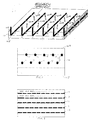
- Figure 1 depicts a schematic three-dimensional view of a subsurface formation 10 having a substantially horizontal upper and lower boundaries 10A and 10B, which formation 10 is penetrated by substantially horizontal segmented lower sections 1A-D,... , 6A-6D of six inert fluid injection wells 1-6.
- Each well 1-6 comprises a segmented lower section 1A-1D, ..., 6A-6D that is divided by valves or other isolation devices into four segments A-D.
- valves or other isolation devices sequentially permit injection of an at least partly liquefied inert fluid slug comprising Nitrogen, Carbon Dioxide, Helium and/or Liquefied Natural Gas (LNG) in a continuous or non continuous manner through one or more well segments 1A-D,... ,6A-6D, which have perforations that permit fluid to liquefied inert fluid to flow into and thereby initially freeze and contract and to subsequently evaporate and expand in the surrounding formation 10, wherein the contraction and subsequent expansion enhances the induced fracturing process without requiring added chemicals.
- LNG Liquefied Natural Gas
- a suitable sequence of opening and closing well segments is 2D->1D, 1D->2C, 2C->1C, 1C->2B, 2B->1B, 1B->2A, 2A->1A, 1A->3D, 3D->2D, 2D->3C, 3C->2C, 2C->3B, 3B->2B, 2B->3A, 3A->2A, 2A->4D, 4D->3D, 3D->4C, 4C->3C, 3C->4B, 4B->3B, 3B->4A, 4A->3A, 3A->5D, ... until each of the infinitive number of horizontal well segments has been opened and subsequently closed.
- inert fluid injection wells 1-6 which each have four substantially horizontal segmented lower section 1A-D,..., 6A-6D as shown in Figure 1 any other number of inert fluid injection wells and any other number (n) of segmented lower sections and valves or other isolation devices may be used.
- Figure 2 is a cross-sectional view of a tight gas, shale gas or Coal Bed Methane(CBM) containing formation 10, or any other type of hydrocarbons containing formation having an substantially horizontal upper and lower boundaries 10A and 10B, which formation is penetrated by horizontal lower sections 11-20 of nine inert fluid injection wells.
- CBM Coal Bed Methane
- the lower sections 11-20 are staggered, such that the lower sections 12, 14, 16, 18 and 20 are located closer to the upper boundary 10A than to the lower boundary 10B, whereas the lower sections 11, 13, 15, 17 and 19 are located closer to the lower boundary 10B than to the upper boundary 10A.
- Figure 3 is a schematic top view of the formation 10 of Figure 2 which shows the lower sections of five wells 12-16 out of the series of nine wells 11-20 shown in Figure 2 .
- Each of these lower sections comprises a suitable number of segments A,B,C,.. Z, etc., wherein the number may be in the order of tens or hundreds that are separated by valves and/or other isolation devices.
- the staggered arrangement of the lower sections of the inert fluid injection wells 11-20 shown in Figures 2 and 3 further enhances the induced fracturing process, so that the formation 10 can be induce fractured by physical and thermodynamic effects initiated by the initial contraction and subsequent expansion of the inert fluids and formation 10 and the induced fracturing associated with the injection of cold substantially liquid inert fluid, which then evaporates in the pores of the formation 10 thereby inducing fracturing in the formation 10 without requiring any or any substantial amount of additional chemicals that could lead to potential causes of pollution of aquifers adjacent to formation 10 and/or the inert fluid injection wells 1-6 and 11-20.
Abstract
A method of induced fracturing of a subsurface formation(10) comprises sequentially injecting at least partly liquefied inert fluid slugs through an array of injection wells (1-6, 11-20) into different parts of the formation(10) such that the formation initially freezes and contracts and subsequently expands due to the evaporation of the inert fluid, thereby enhancing the induced fracturing process.
Description
- The invention relates to a method for induced fracturing in a subsurface formation.
- Methods for fracturing a subsurface formation by injecting a fluid that generates fractures in the formation are known from
US patents 3,664,422 ;3,581,821 ;3,759,329 ;3,842,910 ;7,198,107 ;7,264,049 ;7,416,022 ;7,516,784 ;7,784,545 and7,823,644 , from US patent applicationsUS20060243437 ;US20060065400 ;US20040214728 ;US20080190606 ;US20100270038 ;US2010/005/272 andUS2012/203072 , from Canadian patentsCA2639539 ,CA2644169 , from International patent applicationsW09618801 W0201025540 W02009147394 ;W02009138735 ;W02007988606 andW0200798370 GB2302108 GB2329662 - In conventional fracturing methods large amounts of proppant and water-based fluids with chemical additives are injected, at very high rates, into the formation.
- The traditional water-based fracturing fluids generally can comprise any combination of slickwater, gelled polymer, crosslinkers and gelled LPG mixed with proppants and chemical additives.
- The use of chemical additives has created global controversies regarding the chemicals used in natural gas extraction and claimed negative impact of the hydraulic process on drinking water quality from nearby aquifers. There is a need for an induced fracturing method that requires a reduced amount or no water, proppants or chemical additives and that has less potential of negative impact on drinking water quality from nearby aquifers.
- In accordance with the invention there is provided a method of induced fracturing of a subsurface formation, the method comprising sequentially injecting at least partly liquefied inert fluid slugs into different parts of the formation.
- The formation may comprise a hydrocarbon fluid, such as a natural gas containing tight gas formation, a shale gas formation or a Coal Bed Methane (CBM) containing formation, or any other type of hydrocarbon containing formation, and the liquefied inert fluid slugs may comprise at least one of the following inert fluids: Nitrogen(N2), Carbon Dioxide (CO2), Helium(He) and Liquefied Natural Gas(LNG) and each inert fluid slug may be injected in continuous or non continuous manner and comprise such an amount of inert fluid that at least a section of the formation into which the slug is injected suffers a thermal differential such that it thereby contracts. This formation will subsequently reheat the initial inert fluid slug at least partly evaporating and expanding the gas and thereby generating further induced fractures in the formation.
- As an additional option to the patented technique, after an initial inert fluid slug is injected continuously or non continuously into a first section of the formation a subsequent inert slug may be injected into a second section of the formation, which is located adjacent to the first section and the time interval between injecting the initial and subsequent slugs may be selected such that, at the time when the subsequent inert fluid slug is injected into the second part of the formation and induces at least part of the second section to again suffer a thermal differential and contract, the first section has been heated up by the surrounding formation to such a temperature that the initial inert fluid slug at least partly evaporates and expands and thereby generates further induced fractures in the first section of the formation, wherein the simultaneous expansion of the first section and contraction of the second section enhances the fracturing process.
- These and other features, embodiments and advantages of the method and according to the invention are described in the accompanying claims, abstract and the following detailed description of non-limiting embodiments depicted in the accompanying drawings, in which description reference numerals are used which refer to corresponding reference numerals that are depicted in the drawings. Similar reference numerals in different figures denote the same or similar objects.
-
-
Figure 1 is a schematic three-dimensional view of a subsurface formation penetrated by segmented lower sections of six inert fluid injection wells; -
Figure 2 is a cross-sectional view of a subsurface formation penetrated by segmented lower sections of ten staggered fluid injection wells; and -
Figure 3 is a longitudinal sectional view of the segmented lower section of five of the staggered fluid injection wells shown inFigure 2 . -
Figure 1 depicts a schematic three-dimensional view of asubsurface formation 10 having a substantially horizontal upper andlower boundaries 10A and 10B, whichformation 10 is penetrated by substantially horizontal segmented lower sections 1A-D,... , 6A-6D of six inert fluid injection wells 1-6. Each well 1-6 comprises a segmented lower section 1A-1D, ..., 6A-6D that is divided by valves or other isolation devices into four segments A-D. - The valves or other isolation devices sequentially permit injection of an at least partly liquefied inert fluid slug comprising Nitrogen, Carbon Dioxide, Helium and/or Liquefied Natural Gas (LNG) in a continuous or non continuous manner through one or more well segments 1A-D,... ,6A-6D, which have perforations that permit fluid to liquefied inert fluid to flow into and thereby initially freeze and contract and to subsequently evaporate and expand in the surrounding
formation 10, wherein the contraction and subsequent expansion enhances the induced fracturing process without requiring added chemicals. A suitable sequence of opening and closing well segments is 2D->1D, 1D->2C, 2C->1C, 1C->2B, 2B->1B, 1B->2A, 2A->1A, 1A->3D, 3D->2D, 2D->3C, 3C->2C, 2C->3B, 3B->2B, 2B->3A, 3A->2A, 2A->4D, 4D->3D, 3D->4C, 4C->3C, 3C->4B, 4B->3B, 3B->4A, 4A->3A, 3A->5D, ... until each of the infinitive number of horizontal well segments has been opened and subsequently closed. - It will be understood that instead of using six inert fluid injection wells 1-6 which each have four substantially horizontal segmented lower section 1A-D,..., 6A-6D as shown in
Figure 1 any other number of inert fluid injection wells and any other number (n) of segmented lower sections and valves or other isolation devices may be used. -
Figure 2 is a cross-sectional view of a tight gas, shale gas or Coal Bed Methane(CBM) containingformation 10, or any other type of hydrocarbons containing formation having an substantially horizontal upper andlower boundaries 10A and 10B, which formation is penetrated by horizontal lower sections 11-20 of nine inert fluid injection wells. - The lower sections 11-20 are staggered, such that the
lower sections upper boundary 10A than to the lower boundary 10B, whereas thelower sections upper boundary 10A. -
Figure 3 is a schematic top view of theformation 10 ofFigure 2 which shows the lower sections of five wells 12-16 out of the series of nine wells 11-20 shown inFigure 2 . Each of these lower sections comprises a suitable number of segments A,B,C,.. Z, etc., wherein the number may be in the order of tens or hundreds that are separated by valves and/or other isolation devices. - The staggered arrangement of the lower sections of the inert fluid injection wells 11-20 shown in
Figures 2 and 3 further enhances the induced fracturing process, so that theformation 10 can be induce fractured by physical and thermodynamic effects initiated by the initial contraction and subsequent expansion of the inert fluids andformation 10 and the induced fracturing associated with the injection of cold substantially liquid inert fluid, which then evaporates in the pores of theformation 10 thereby inducing fracturing in theformation 10 without requiring any or any substantial amount of additional chemicals that could lead to potential causes of pollution of aquifers adjacent toformation 10 and/or the inert fluid injection wells 1-6 and 11-20.
Claims (14)
- A method of Induced fracturing of a subsurface formation, the method comprising sequentially injecting at least partly liquefied inert fluid slugs into different parts of the formation.
- The method of claim 1, wherein the at least partly liquefied inert fluid slugs comprise at least one of the following inert fluids: Nitrogen, Carbon Dioxide, Helium and Liquefied Natural Gas.
- The method of claim 2, wherein each inert fluid slug comprises such an amount of inert fluid that at least a section of the formation into which the slug is injected freezes and thereby contracts.
- The method of claim 3, wherein after an initial inert fluid slug is injected into a first section of the formation a subsequent inert slug is injected into a second section of the formation, which is located adjacent or nearby to the first section.
- The method of claim 4, wherein the time interval between injecting the initial and subsequent slugs is selected such that, at the time when the subsequent inert fluid slug is injected into the second part of the formation and induces at least part of the second section to freeze and contract, the first section has been heated up to such a temperature that the initial inert fluid slug at least partly evaporates and expands and thereby generates fractures in the first section of the formation.
- The method of claim 5, wherein the simultaneous expansion of the first section and contraction of the second section enhances the fracturing process.
- The method of any one of claims 1-6, wherein the subsurface formation comprises a hydrocarbon fluid, which is induced to flow from the fractured formation to hydrocarbon fluid production facilities at the earth surface after completion of the fracturing method.
- The method of claim 7, wherein the subsurface formation has an upper and a lower boundary and is penetrated by a plurality of inert fluid injection wells.
- The method of claim 8, wherein at least two of the fluid injection wells each have a lower section that extends substantially parallel to the lower section of another fluid injection well and to the lower and/or lower boundary of the subsurface formation.
- The method of claim 9, wherein at least two of the fluid injection wells each have a lower section that is divided into a plurality of longitudinally spaced segments that are separated by a valve system that permits inert fluid to flow from one segment into the formation, whilst blocking fluid flow from each other segment into the formation.
- The method of claim 9 or 10, wherein the lower section of at least one fluid injection well is located at a smaller average distance from the upper boundary than the lower section of at least one other fluid injection well.
- The method of claim 11, wherein the formation is penetrated by at least four inert fluid injection wells having staggered lower sections that are alternatingly located at a smaller average distance from the upper boundary than from the lower boundary and at a smaller average distance from the lower boundary than from the upper boundary.
- The method of any one of claims 7-12, wherein the formation is a shale gas formation, a tight gas formation or a formation comprising coal bed methane.
- The method of any one of claims 7-13, wherein the inert fluid injection wells are configured to initially inject a sequence of inert fluid slugs adjacent to one lateral boundary of the formation and to gradually migrate the injection of subsequent sequences of inert fluid slugs towards an opposite lateral boundary of the formation.
Priority Applications (1)
| Application Number | Priority Date | Filing Date | Title |
|---|---|---|---|
| EP11167877A EP2527586A1 (en) | 2011-05-27 | 2011-05-27 | Method for induced fracturing in a subsurface formation |
Applications Claiming Priority (1)
| Application Number | Priority Date | Filing Date | Title |
|---|---|---|---|
| EP11167877A EP2527586A1 (en) | 2011-05-27 | 2011-05-27 | Method for induced fracturing in a subsurface formation |
Publications (1)
| Publication Number | Publication Date |
|---|---|
| EP2527586A1 true EP2527586A1 (en) | 2012-11-28 |
Family
ID=44582080
Family Applications (1)
| Application Number | Title | Priority Date | Filing Date |
|---|---|---|---|
| EP11167877A Withdrawn EP2527586A1 (en) | 2011-05-27 | 2011-05-27 | Method for induced fracturing in a subsurface formation |
Country Status (1)
| Country | Link |
|---|---|
| EP (1) | EP2527586A1 (en) |
Cited By (13)
| Publication number | Priority date | Publication date | Assignee | Title |
|---|---|---|---|---|
| WO2016110185A1 (en) * | 2015-01-06 | 2016-07-14 | 中国矿业大学 | Method for gas extraction alternating oscillating pulse high energy gas extraction with thermal injection |
| WO2016110183A1 (en) * | 2015-01-06 | 2016-07-14 | 中国矿业大学 | Method for integrated drilling, flushing, slotting and thermal injection for coalbed gas extraction |
| WO2017075935A1 (en) * | 2015-11-06 | 2017-05-11 | 中国矿业大学 | Method of increasing permeability of coal seam using high-power electric blasting assisted by hydraulic fracturing from bottom drainage roadway |
| US9688905B2 (en) | 2013-11-11 | 2017-06-27 | Halliburton Energy Services, Inc. | Methods for enhancing propped fracture conductivity |
| US9790774B2 (en) | 2014-01-02 | 2017-10-17 | Halliburton Energy Services, Inc. | Generating and maintaining conductivity of microfractures in tight formations by generating gas and heat |
| US10023789B2 (en) | 2014-09-02 | 2018-07-17 | Halliburton Energy Services, Inc. | Enhancing complex fracture networks in subterranean formations |
| US10301917B2 (en) | 2015-07-24 | 2019-05-28 | Halliburton Energy Services, Inc. | Microbubbles for treatment chemical delivery in subterranean formations |
| US10308868B2 (en) | 2014-01-02 | 2019-06-04 | Halliburton Energy Services, Inc. | Generating and enhancing microfracture conductivity |
| CN110424937A (en) * | 2019-07-15 | 2019-11-08 | 河南理工大学 | A kind of coal bed gas low yield well nitrogen-carbon dioxide joint transformation method for increasing |
| US10570730B2 (en) | 2015-06-03 | 2020-02-25 | Geomec Engineering Limited | Hydrocarbon filled fracture formation testing before shale fracturing |
| US10626321B2 (en) | 2015-07-24 | 2020-04-21 | Halliburton Energy Services, Inc. | Microbubbles for heat and/or gas generation in subterranean formations |
| US11053431B2 (en) | 2014-10-03 | 2021-07-06 | Halliburton Energy Services, Inc. | Fly ash microspheres for use in subterranean formation operations |
| US11365346B2 (en) | 2018-02-09 | 2022-06-21 | Halliburton Energy Services, Inc. | Methods of ensuring and enhancing conductivity in micro-fractures |
Citations (23)
| Publication number | Priority date | Publication date | Assignee | Title |
|---|---|---|---|---|
| US3581821A (en) | 1969-05-09 | 1971-06-01 | Petra Flow Inc | Cryothermal process for the recovery of oil |
| US3664422A (en) | 1970-08-17 | 1972-05-23 | Dresser Ind | Well fracturing method employing a liquified gas and propping agents entrained in a fluid |
| US3759329A (en) | 1969-05-09 | 1973-09-18 | Shuffman O | Cryo-thermal process for fracturing rock formations |
| US3822747A (en) * | 1973-05-18 | 1974-07-09 | J Maguire | Method of fracturing and repressuring subsurface geological formations employing liquified gas |
| US3842910A (en) | 1973-10-04 | 1974-10-22 | Dow Chemical Co | Well fracturing method using liquefied gas as fracturing fluid |
| WO1996018801A1 (en) | 1994-12-14 | 1996-06-20 | Conoco Inc. | Cryogenic coal bed gas well stimulation method |
| GB2302108A (en) | 1995-06-09 | 1997-01-08 | Conoco Inc | Cryogenic well stimulation method |
| GB2329662A (en) | 1995-06-09 | 1999-03-31 | Conoco Inc | Cryogenic well stimulation method |
| US20040214728A1 (en) | 2001-02-23 | 2004-10-28 | Taylor Robert S. | Methods and compositions for treating subterranean formations with gelled hydrocarbon fluids |
| CA2644169A1 (en) | 2004-02-26 | 2005-09-09 | Halliburton Energy Services, Inc. | Compositions and methods for treating subterranean formations with liquefied petroleum gas |
| US20060065400A1 (en) | 2004-09-30 | 2006-03-30 | Smith David R | Method and apparatus for stimulating a subterranean formation using liquefied natural gas |
| US20060243437A1 (en) | 2005-04-29 | 2006-11-02 | Blair Albers | Method for fracture stimulating well bores |
| US7198107B2 (en) | 2004-05-14 | 2007-04-03 | James Q. Maguire | In-situ method of producing oil shale and gas (methane) hydrates, on-shore and off-shore |
| WO2007098370A2 (en) | 2006-02-16 | 2007-08-30 | Chevron U.S.A. Inc. | Kerogen extraction from subterranean oil shale resources |
| US7264049B2 (en) | 2004-05-14 | 2007-09-04 | Maguire James Q | In-situ method of coal gasification |
| CA2568358A1 (en) * | 2006-11-17 | 2008-05-17 | James Q. Maguire | In-situ method of producing oil and gas (methane), on-shore and off-shore |
| WO2009138735A2 (en) | 2008-05-15 | 2009-11-19 | Halliburton Energy Services, Inc. | Methods of initiating intersecting fractures using explosive and cryogenic means |
| WO2009147394A1 (en) | 2008-06-06 | 2009-12-10 | Halliburton Energy Services, Inc. | Methods of treating subterranean formations utilizing servicing fluids comprising liquefied petroleum gas and apparatus thereof |
| US20100005272A1 (en) | 2004-04-20 | 2010-01-07 | Miljan Vuletic | Virtual memory window with dynamic prefetching support |
| CA2639539A1 (en) | 2008-09-02 | 2010-03-02 | Gasfrac Energy Services Inc. | Liquified petroleum gas fracturing methods |
| WO2010025540A1 (en) | 2008-09-02 | 2010-03-11 | Gasfrac Energy Services Inc. | Liquified petroleum gas fracturing methods |
| US7784545B2 (en) | 2004-05-14 | 2010-08-31 | Maguire James Q | In-situ method of fracturing gas shale and geothermal areas |
| US20120203072A1 (en) | 2001-12-08 | 2012-08-09 | Transcardiac Therapeutics, Inc. | Apical Instrument Port |
-
2011
- 2011-05-27 EP EP11167877A patent/EP2527586A1/en not_active Withdrawn
Patent Citations (28)
| Publication number | Priority date | Publication date | Assignee | Title |
|---|---|---|---|---|
| US3581821A (en) | 1969-05-09 | 1971-06-01 | Petra Flow Inc | Cryothermal process for the recovery of oil |
| US3759329A (en) | 1969-05-09 | 1973-09-18 | Shuffman O | Cryo-thermal process for fracturing rock formations |
| US3664422A (en) | 1970-08-17 | 1972-05-23 | Dresser Ind | Well fracturing method employing a liquified gas and propping agents entrained in a fluid |
| US3822747A (en) * | 1973-05-18 | 1974-07-09 | J Maguire | Method of fracturing and repressuring subsurface geological formations employing liquified gas |
| US3842910A (en) | 1973-10-04 | 1974-10-22 | Dow Chemical Co | Well fracturing method using liquefied gas as fracturing fluid |
| WO1996018801A1 (en) | 1994-12-14 | 1996-06-20 | Conoco Inc. | Cryogenic coal bed gas well stimulation method |
| GB2302108A (en) | 1995-06-09 | 1997-01-08 | Conoco Inc | Cryogenic well stimulation method |
| GB2329662A (en) | 1995-06-09 | 1999-03-31 | Conoco Inc | Cryogenic well stimulation method |
| US20040214728A1 (en) | 2001-02-23 | 2004-10-28 | Taylor Robert S. | Methods and compositions for treating subterranean formations with gelled hydrocarbon fluids |
| US20120203072A1 (en) | 2001-12-08 | 2012-08-09 | Transcardiac Therapeutics, Inc. | Apical Instrument Port |
| CA2644169A1 (en) | 2004-02-26 | 2005-09-09 | Halliburton Energy Services, Inc. | Compositions and methods for treating subterranean formations with liquefied petroleum gas |
| US20100005272A1 (en) | 2004-04-20 | 2010-01-07 | Miljan Vuletic | Virtual memory window with dynamic prefetching support |
| US7784545B2 (en) | 2004-05-14 | 2010-08-31 | Maguire James Q | In-situ method of fracturing gas shale and geothermal areas |
| US7264049B2 (en) | 2004-05-14 | 2007-09-04 | Maguire James Q | In-situ method of coal gasification |
| US7416022B2 (en) | 2004-05-14 | 2008-08-26 | Maguire James Q | In-situ method of producing oil shale, on-shore and off-shore |
| US7516784B2 (en) | 2004-05-14 | 2009-04-14 | Maguire James Q | In-situ method of coal gasification |
| US20080190606A1 (en) | 2004-05-14 | 2008-08-14 | Maguire James Q | In-situ method of producing oil shale, on-shore and off-shore |
| US7823644B2 (en) | 2004-05-14 | 2010-11-02 | Maguire James Q | In-situ method of producing oil shale, on-shore and off-shore |
| US7198107B2 (en) | 2004-05-14 | 2007-04-03 | James Q. Maguire | In-situ method of producing oil shale and gas (methane) hydrates, on-shore and off-shore |
| US20060065400A1 (en) | 2004-09-30 | 2006-03-30 | Smith David R | Method and apparatus for stimulating a subterranean formation using liquefied natural gas |
| US20060243437A1 (en) | 2005-04-29 | 2006-11-02 | Blair Albers | Method for fracture stimulating well bores |
| US20100270038A1 (en) | 2006-02-16 | 2010-10-28 | Chevron U.S.A. Inc. | Kerogen Extraction from Subterranean Oil Shale Resources |
| WO2007098370A2 (en) | 2006-02-16 | 2007-08-30 | Chevron U.S.A. Inc. | Kerogen extraction from subterranean oil shale resources |
| CA2568358A1 (en) * | 2006-11-17 | 2008-05-17 | James Q. Maguire | In-situ method of producing oil and gas (methane), on-shore and off-shore |
| WO2009138735A2 (en) | 2008-05-15 | 2009-11-19 | Halliburton Energy Services, Inc. | Methods of initiating intersecting fractures using explosive and cryogenic means |
| WO2009147394A1 (en) | 2008-06-06 | 2009-12-10 | Halliburton Energy Services, Inc. | Methods of treating subterranean formations utilizing servicing fluids comprising liquefied petroleum gas and apparatus thereof |
| WO2010025540A1 (en) | 2008-09-02 | 2010-03-11 | Gasfrac Energy Services Inc. | Liquified petroleum gas fracturing methods |
| CA2639539A1 (en) | 2008-09-02 | 2010-03-02 | Gasfrac Energy Services Inc. | Liquified petroleum gas fracturing methods |
Cited By (19)
| Publication number | Priority date | Publication date | Assignee | Title |
|---|---|---|---|---|
| US9688905B2 (en) | 2013-11-11 | 2017-06-27 | Halliburton Energy Services, Inc. | Methods for enhancing propped fracture conductivity |
| US9790774B2 (en) | 2014-01-02 | 2017-10-17 | Halliburton Energy Services, Inc. | Generating and maintaining conductivity of microfractures in tight formations by generating gas and heat |
| US10308868B2 (en) | 2014-01-02 | 2019-06-04 | Halliburton Energy Services, Inc. | Generating and enhancing microfracture conductivity |
| US10023789B2 (en) | 2014-09-02 | 2018-07-17 | Halliburton Energy Services, Inc. | Enhancing complex fracture networks in subterranean formations |
| US11053431B2 (en) | 2014-10-03 | 2021-07-06 | Halliburton Energy Services, Inc. | Fly ash microspheres for use in subterranean formation operations |
| AU2015376361B2 (en) * | 2015-01-06 | 2017-07-13 | China University Of Mining And Technology | Method for gas extraction alternating oscillating pulse high energy gas extraction with thermal injection |
| US10378327B2 (en) | 2015-01-06 | 2019-08-13 | China University Of Mining And Technology | Method for gas extraction alternating oscillating pulse high energy gas extraction with thermal injection |
| WO2016110183A1 (en) * | 2015-01-06 | 2016-07-14 | 中国矿业大学 | Method for integrated drilling, flushing, slotting and thermal injection for coalbed gas extraction |
| WO2016110185A1 (en) * | 2015-01-06 | 2016-07-14 | 中国矿业大学 | Method for gas extraction alternating oscillating pulse high energy gas extraction with thermal injection |
| US10370942B2 (en) | 2015-01-06 | 2019-08-06 | China University Of Mining And Technology | Method for integrated drilling, flushing, slotting and thermal injection for coalbed gas extraction |
| US10570730B2 (en) | 2015-06-03 | 2020-02-25 | Geomec Engineering Limited | Hydrocarbon filled fracture formation testing before shale fracturing |
| US10570729B2 (en) | 2015-06-03 | 2020-02-25 | Geomec Engineering Limited | Thermally induced low flow rate fracturing |
| US10641089B2 (en) | 2015-06-03 | 2020-05-05 | Geomec Engineering, Ltd. | Downhole pressure measuring tool with a high sampling rate |
| US10626321B2 (en) | 2015-07-24 | 2020-04-21 | Halliburton Energy Services, Inc. | Microbubbles for heat and/or gas generation in subterranean formations |
| US10301917B2 (en) | 2015-07-24 | 2019-05-28 | Halliburton Energy Services, Inc. | Microbubbles for treatment chemical delivery in subterranean formations |
| WO2017075935A1 (en) * | 2015-11-06 | 2017-05-11 | 中国矿业大学 | Method of increasing permeability of coal seam using high-power electric blasting assisted by hydraulic fracturing from bottom drainage roadway |
| US11365346B2 (en) | 2018-02-09 | 2022-06-21 | Halliburton Energy Services, Inc. | Methods of ensuring and enhancing conductivity in micro-fractures |
| US11845895B2 (en) | 2018-02-09 | 2023-12-19 | Halliburton Energy Services, Inc. | Methods of ensuring and enhancing conductivity in micro-fractures |
| CN110424937A (en) * | 2019-07-15 | 2019-11-08 | 河南理工大学 | A kind of coal bed gas low yield well nitrogen-carbon dioxide joint transformation method for increasing |
Similar Documents
| Publication | Publication Date | Title |
|---|---|---|
| EP2527586A1 (en) | Method for induced fracturing in a subsurface formation | |
| US10927655B2 (en) | Pressure assisted oil recovery | |
| US10577533B2 (en) | Unconventional enhanced oil recovery | |
| US10018025B2 (en) | Hydraulic fracturing system and method | |
| Wang et al. | Mechanistic simulation study of gas Puff and Huff process for Bakken tight oil fractured reservoir | |
| CN103306660B (en) | A kind of method of shale gas reservoir fracturing volume increase | |
| US9127544B2 (en) | Fluid injection in light tight oil reservoirs | |
| Shafiei et al. | Geomechanics of thermal viscous oil production in sandstones | |
| EA010677B1 (en) | Hydrocarbon recovery from impermeable oil shales | |
| US20150083398A1 (en) | Producing hydrocarbons | |
| CN105822276B (en) | Interval while water injection oil extraction method between multistage fracturing horizontal well seam | |
| Ocampo et al. | Successful foam EOR pilot in a mature volatile oil reservoir under miscible gas injection | |
| US20150152719A1 (en) | Enhanced Secondary Recovery of Oil and Gas in Tight Hydrocarbon Reservoirs | |
| US20120205127A1 (en) | Selective displacement of water in pressure communication with a hydrocarbon reservoir | |
| CA2764343A1 (en) | Enhanced hydrocarbon recovery from low mobility reservoirs | |
| US20140318773A1 (en) | Methane enhanced liquid products recovery from wet natural gas | |
| Ezeuko et al. | Towards the development of bitumen carbonates: an integrated analysis of Grosmont steam pilots | |
| US9309741B2 (en) | System and method for temporarily sealing a bore hole | |
| US20140076566A1 (en) | Use of Underground Access to Improve Steam Distribution in SAGD Operations | |
| Marin Sr | Hydrocarbon solvent injection study for heavy oil recovery in the Colombian oil sands | |
| Mahmud et al. | Investigate Polymer Flooding for Enhanced Oil Recovery in a Mature Oil Field | |
| Suranto et al. | Controlling the hybrid steam-solvent injection for increasing recovery factor and reducing solvent retention in heterogeneous reservoirs | |
| Taheriotaghsara et al. | Field case studies of gas injection methods | |
| Abbasi et al. | Simulation study for production of heavy oil: A case study of soroosh oil field, Southern Iran | |
| Kumar | Design of a Gas Lift System to Increase Oil Production for Offshore Wells with High Water Cut |
Legal Events
| Date | Code | Title | Description |
|---|---|---|---|
| PUAI | Public reference made under article 153(3) epc to a published international application that has entered the european phase |
Free format text: ORIGINAL CODE: 0009012 |
|
| AK | Designated contracting states |
Kind code of ref document: A1 Designated state(s): AL AT BE BG CH CY CZ DE DK EE ES FI FR GB GR HR HU IE IS IT LI LT LU LV MC MK MT NL NO PL PT RO RS SE SI SK SM TR |
|
| AX | Request for extension of the european patent |
Extension state: BA ME |
|
| STAA | Information on the status of an ep patent application or granted ep patent |
Free format text: STATUS: THE APPLICATION IS DEEMED TO BE WITHDRAWN |
|
| 18D | Application deemed to be withdrawn |
Effective date: 20130529 |