EP2543540A1 - Optical fibre, illuminant and motor vehicle light - Google Patents
Optical fibre, illuminant and motor vehicle light Download PDFInfo
- Publication number
- EP2543540A1 EP2543540A1 EP11173077A EP11173077A EP2543540A1 EP 2543540 A1 EP2543540 A1 EP 2543540A1 EP 11173077 A EP11173077 A EP 11173077A EP 11173077 A EP11173077 A EP 11173077A EP 2543540 A1 EP2543540 A1 EP 2543540A1
- Authority
- EP
- European Patent Office
- Prior art keywords
- light
- light guide
- optical fiber
- prism
- motor vehicle
- Prior art date
- Legal status (The legal status is an assumption and is not a legal conclusion. Google has not performed a legal analysis and makes no representation as to the accuracy of the status listed.)
- Withdrawn
Links
Images


Classifications
-
- G—PHYSICS
- G02—OPTICS
- G02B—OPTICAL ELEMENTS, SYSTEMS OR APPARATUS
- G02B6/00—Light guides; Structural details of arrangements comprising light guides and other optical elements, e.g. couplings
- G02B6/0001—Light guides; Structural details of arrangements comprising light guides and other optical elements, e.g. couplings specially adapted for lighting devices or systems
- G02B6/0011—Light guides; Structural details of arrangements comprising light guides and other optical elements, e.g. couplings specially adapted for lighting devices or systems the light guides being planar or of plate-like form
- G02B6/0033—Means for improving the coupling-out of light from the light guide
- G02B6/0035—Means for improving the coupling-out of light from the light guide provided on the surface of the light guide or in the bulk of it
- G02B6/0038—Linear indentations or grooves, e.g. arc-shaped grooves or meandering grooves, extending over the full length or width of the light guide
-
- F—MECHANICAL ENGINEERING; LIGHTING; HEATING; WEAPONS; BLASTING
- F21—LIGHTING
- F21S—NON-PORTABLE LIGHTING DEVICES; SYSTEMS THEREOF; VEHICLE LIGHTING DEVICES SPECIALLY ADAPTED FOR VEHICLE EXTERIORS
- F21S43/00—Signalling devices specially adapted for vehicle exteriors, e.g. brake lamps, direction indicator lights or reversing lights
- F21S43/20—Signalling devices specially adapted for vehicle exteriors, e.g. brake lamps, direction indicator lights or reversing lights characterised by refractors, transparent cover plates, light guides or filters
- F21S43/235—Light guides
- F21S43/236—Light guides characterised by the shape of the light guide
- F21S43/237—Light guides characterised by the shape of the light guide rod-shaped
-
- F—MECHANICAL ENGINEERING; LIGHTING; HEATING; WEAPONS; BLASTING
- F21—LIGHTING
- F21S—NON-PORTABLE LIGHTING DEVICES; SYSTEMS THEREOF; VEHICLE LIGHTING DEVICES SPECIALLY ADAPTED FOR VEHICLE EXTERIORS
- F21S43/00—Signalling devices specially adapted for vehicle exteriors, e.g. brake lamps, direction indicator lights or reversing lights
- F21S43/20—Signalling devices specially adapted for vehicle exteriors, e.g. brake lamps, direction indicator lights or reversing lights characterised by refractors, transparent cover plates, light guides or filters
- F21S43/235—Light guides
- F21S43/236—Light guides characterised by the shape of the light guide
- F21S43/239—Light guides characterised by the shape of the light guide plate-shaped
-
- F—MECHANICAL ENGINEERING; LIGHTING; HEATING; WEAPONS; BLASTING
- F21—LIGHTING
- F21S—NON-PORTABLE LIGHTING DEVICES; SYSTEMS THEREOF; VEHICLE LIGHTING DEVICES SPECIALLY ADAPTED FOR VEHICLE EXTERIORS
- F21S43/00—Signalling devices specially adapted for vehicle exteriors, e.g. brake lamps, direction indicator lights or reversing lights
- F21S43/20—Signalling devices specially adapted for vehicle exteriors, e.g. brake lamps, direction indicator lights or reversing lights characterised by refractors, transparent cover plates, light guides or filters
- F21S43/235—Light guides
- F21S43/242—Light guides characterised by the emission area
- F21S43/245—Light guides characterised by the emission area emitting light from one or more of its major surfaces
-
- G—PHYSICS
- G02—OPTICS
- G02B—OPTICAL ELEMENTS, SYSTEMS OR APPARATUS
- G02B6/00—Light guides; Structural details of arrangements comprising light guides and other optical elements, e.g. couplings
- G02B6/0001—Light guides; Structural details of arrangements comprising light guides and other optical elements, e.g. couplings specially adapted for lighting devices or systems
- G02B6/0011—Light guides; Structural details of arrangements comprising light guides and other optical elements, e.g. couplings specially adapted for lighting devices or systems the light guides being planar or of plate-like form
- G02B6/0033—Means for improving the coupling-out of light from the light guide
- G02B6/0035—Means for improving the coupling-out of light from the light guide provided on the surface of the light guide or in the bulk of it
- G02B6/004—Scattering dots or dot-like elements, e.g. microbeads, scattering particles, nanoparticles
- G02B6/0043—Scattering dots or dot-like elements, e.g. microbeads, scattering particles, nanoparticles provided on the surface of the light guide
-
- G—PHYSICS
- G02—OPTICS
- G02B—OPTICAL ELEMENTS, SYSTEMS OR APPARATUS
- G02B6/00—Light guides; Structural details of arrangements comprising light guides and other optical elements, e.g. couplings
- G02B6/0001—Light guides; Structural details of arrangements comprising light guides and other optical elements, e.g. couplings specially adapted for lighting devices or systems
- G02B6/0011—Light guides; Structural details of arrangements comprising light guides and other optical elements, e.g. couplings specially adapted for lighting devices or systems the light guides being planar or of plate-like form
- G02B6/0033—Means for improving the coupling-out of light from the light guide
- G02B6/0058—Means for improving the coupling-out of light from the light guide varying in density, size, shape or depth along the light guide
Definitions
- the invention relates to a light guide according to the preamble of claim 1, a light source comprising such a light guide according to the preamble of claim 9 and a motor vehicle light having at least one aforementioned light source according to the preamble of claim 10.
- a motor vehicle lamp essentially comprises a lamp housing enclosed by a lamp housing and a lens, and at least one lamp housed therein for at least one light function of the motor vehicle lamp.
- At least one reflector arranged behind at least one part of a luminous means for example behind at least one light source of the at least one luminous means, can be accommodated in the luminaire interior.
- the reflector can be formed at least in part by a separate component and / or by at least one part of the luminaire housing itself, for example by means of an at least partially reflective coating.
- At least one light source of the illuminant may comprise one or more optical elements, such as at least one lens, at least one channel concentrator, e.g. at least one parabolic trough (CPC) or the like for forming a defined emission characteristic.
- optical elements such as at least one lens, at least one channel concentrator, e.g. at least one parabolic trough (CPC) or the like for forming a defined emission characteristic.
- the lens is formed by a transparent cover, which protects the interior of the lamp and the components housed by this against the weather.
- At least one optical disk can be arranged in the beam path between at least one light source of the luminous means and the light disk, which can have a specific structure and / or masking, for example, with a clear lens, for example a light effect for a viewer, the luminous means and / or its at least one light source to conceal.
- the luminaire housing or the luminaire interior can be divided into several chambers, each with its own light sources and / or light sources, possibly reflectors and / or optical elements and / or optical discs, as well as optionally Lenses be divided, of which several chambers can be the same or each chamber can fulfill a different lighting functions.
- a light function is a function of the motor vehicle light intended to fulfill a task.
- Each motor vehicle light fulfills one or more tasks or functions depending on the design.
- a light function of the motor vehicle light is provided.
- Light functions are, for example, in a configuration as a headlamp a function illuminating the road surface, or in a configuration as a signal light, a signal function, such as a Wiederblinklichtfunktion to the direction indicator or a brake light function to indicate a braking action, or.
- a limiting light function such as a taillight function, to ensure visibility of the vehicle during the day and / or night, such as in a taillight or daytime running light configuration.
- motor vehicle lights are thesselbug, on the vehicle flanks and / or on the side mirrors and arranged at the rear of vehicle rear lights, exit lights, for example, ambient lighting, marker lights, brake lights, fog lamps, reversing lights, and typically high set third brake lights, so-called Central, High-Mounted Braking lights, daytime running lights, headlamps and fog lights used as turning or cornering lights, as well as combinations thereof.
- a luminous means for at least one light function comprises at least at least one light source, for example at least one incandescent lamp or at least one gas discharge lamp or at least one light-emitting diode and optionally combinations thereof.
- LEDs come as light sources of lamps for automotive lighting, inter alia, because of their low power consumption LEDs increasingly used. These consist of at least one light-emitting diode semiconductor chip, short LED chip, as well as at least one, for example, molded by injection molding, the at least one LED chip completely or partially enveloping primary optics. Also, automotive lights are known in which pure LED chips are used without molded primary optics. In the following, therefore, for the sake of simplicity, no distinction is made between light-emitting diode and LED chip and instead, the term LED is used uniformly for both embodiments, unless explicitly stated otherwise. Outstanding properties of LEDs compared to other, conventional light sources of bulbs are a much longer life and a significantly higher light output with the same power consumption. As a result, and among other things also because of their more compact dimensions can be realized by using LEDs as a light source of light bulbs particularly compact automotive lights, which can be adapted to almost every imaginable installation situation.
- one or more optical fibers may be provided, for example to provide a desired light distribution e.g. across the lens of the light emitted by one or more light sources.
- An optical waveguide in which light is coupled in at least one light source to at least one light coupling surface and coupled back to at least one light coupling surface that is different from the light coupling surface can be accommodated as a separate component in the interior of the luminaire or be part of a light source.
- a luminous means may comprise one or more light guides and one or more light sources emitting light from them, at least in part into the light sources coupling in at least one light guide.
- An optical waveguide of such a luminous means can serve, for example, as a primary optic of one or more LEDs or be designed as such a primary optic.
- the optical waveguide can be configured, for example, in the form of a bar as a so-called bar light guide and / or as a so-called planar light guide, with a light output surface arranged on its front side oriented, for example, normal to the main emission direction of a motor vehicle light.
- the light emerging from a light coupling surface in such a light guide of a certain, prescribed in a motor vehicle light distribution in one or more preferred directions and luminance in this one or more preferred directions of Lichtauskopplung from the light guide are, for example, on one of the light output surface opposite back of the light guide intended Lichtleiterauskoppel Modellen with a directed Coupling of the coupled into the light guide light in one or more preferred directions, for example, over the entire length of the light guide away known.
- These light guide outcoupling structures comprise a totally reflecting prism structure arranged, for example, on the light guide backside, which redirects the light in the light guide and on an opposite or adjacent light outcoupling surface with refraction at the transition from the light guide material to the surrounding air in at least one preferred direction while maintaining the lighting requirements in the at least one preferred direction decoupling sufficient luminance.
- decoupling surface In addition, light guides with a smooth optical fiber back and a rough front surface are known as decoupling surface.
- Prismatic structures on two optical fiber rear side parts which jointly form the optical fiber rear side serve for decoupling of light in a preferred direction oriented normal to the optical fiber rear side, planar light output surface.
- a uniform illumination of the light output surface is obtained by means of overlapping, opposing prismatic structures on the two Lichtleiterschreibn opposite the light output surface and two-sided light coupling to two opposite, the end regions of the light guide element forming and the light outcoupling surface with the Lichtleiter Wegseite connecting light
- a bright appearance of the end regions of the light guide when viewed from a direction corresponding to the preferred direction of the light extraction direction normal to the formed by a light guide front light output surface.
- the disadvantage of this is that when several preferred directions are to be realized with such a light guide element, no homogeneous luminance distribution can be obtained.
- the planar light guide element is not suitable to follow a curved course of a lens.
- the straight, rod-shaped light guide over its entire length has an identical preferred direction of light extraction with respect to the light output surface. If the rod-shaped optical waveguide is arranged curved, this preferred direction changes with the local orientation of the light exit surface of the optical waveguide which changes as a result of the curvature. Compliance with legal requirements regarding light distribution and luminance is thus possible only by a corresponding increase in the coupled light intensity, along with the aforementioned disadvantages of a high space requirement for the correspondingly sized at least one light source, the higher cost due to the stronger and / or more required for this Light sources, as well as the unnecessarily high power consumption associated with a higher load and thus design of the electrical system of a motor vehicle.
- the optical waveguide has metrologically homogeneous luminance in the preferred direction over its length, it appears to be of different brightness and differently illuminated in its width, in particular in the case of a curved course over its length.
- the invention is based on the object to develop a light guide, a light source with a light guide and a motor vehicle light with a light guide comprising bulbs, which light extraction in one or more, in their orientation to a local surface normal light extraction surface different preferred directions at the same time homogeneous Have luminance distribution.
- a first subject of the invention accordingly relates to a light guide, for example of a rod, preferably curved in a plane and / or particularly preferably three-dimensionally in space with at least one light coupling surface, at least one light coupling surface different from the at least one light coupling surface, and at least one of the at least one light coupling surface different light deflection surface.
- the at least one light deflection surface is preferably arranged on at least one light guide rear side opposite the at least one light output surface or comprises or comprises such.
- At least one Lichtumlenk materials is provided with a hybrid Lichtleiterauskoppel Modell.
- the hybrid Lichtleiterauskoppel Gent consists of at least a first Lichtleiterauskoppel Design-lot and at least one adjacent to at least a first Lichtleiterauskoppel Design-part second Lichtleiterauskoppel Design-Lotie.
- the at least one first Lichtleiterauskoppel Design-lot preferably comprises at least partially at least one example total reflecting prism structure, by means of coupled into the light guide at least one Lichteinkoppeles light specifically deflected in one or more directions to the light outcoupling surface and at the light outcoupling surface under refraction in the transition from the light guide material to surrounding medium, for example to the surrounding air, in at least one preferred direction in compliance with a legally prescribed, for example, lighting requirements for a motor vehicle light in one or more preferred directions sufficient luminance is coupled.
- the preferred directions are defined by a likewise, for example, legally prescribed light distribution.
- the at least one adjoining at least a first Lichtleiterauskoppel Design-part second Lichtleiterauskoppel Design-lot preferably comprises at least one diffuser structure, deflected by means of coupled into the light guide at least one Lichteinkoppeles light with a random distribution and at the light outcoupling surface under refraction in the transition from the optical fiber material to surrounding medium is diffusely decoupled.
- the prism structure preferably comprises at least one effective surface of at least one prism element defined according to the lighting requirements in one or more preferred directions and the luminance in the at least one preferred direction.
- the prism element is preferably a structure having one or more effective internal surfaces causing total internal reflection in the light guide.
- a prism structure comprising one or more such prism elements can also be called a totally reflecting prism structure.
- the prism structure thus ensures compliance with lighting requirements.
- the diffuser structure comprises at least one surface with a statistical distribution of the active elements which cause the diffuse decoupling which causes the diffuse decoupling, for example, by means of a targeted surface roughness subject to a statistical distribution.
- the active elements are, for example, light-deflecting, small surface sections with dimensions in the dimension of the surface roughness.
- the diffuser structure thus ensures that a homogeneous impression of the light guide for the viewer from different directions.
- the second optical fiber extraction structure part may be one or more photometrically ineffective or for the light distribution in the at least one preferred direction ineffective surfaces, such as comprise one or more end faces of the prism elements of the prism structure. These surfaces, for example, comprising faces, can be roughened or provided with a predetermined surface roughness.
- the second Lichtleiterauskoppel devised between extending in the extension direction, for example, a rod-shaped light guide and / or transverse to the extension direction, for example, a rod-shaped light guide prism elements lying surface sections. These surface sections may be executed roughened or provided with a predetermined surface roughness.
- Neighboring prism elements of the prism structure of the first light guide outcoupling structure portion may be formed differently wide and / or differently high and / or differently inclined on their front and / or rear side, for example, standing up on a light guide rear side.
- adjacent prism elements may have different orientations relative to a central axis of the, for example, rod-shaped optical waveguide.
- the central axis can be defined, for example, as a continuous or unsteady mathematical curve on which the centers of gravity of all successive cross-sectional areas of the light guide lie.
- surface portions may have the same and / or different dimensions and / or same and / or different geometries in and / or transverse to the central axis of the light guide.
- the prism structure may comprise pyramid-shaped prism elements, so-called dots, with lateral surfaces rising and striking in a point. Of these lateral surfaces may comprise one, several or all photometrically effective active surfaces.
- the prism structure may alternatively or additionally comprise sawtooth-shaped prism elements with only two line-like, effective active surfaces which are adjacent to each other in a line, and also surfaces which terminate on both sides and which are ineffective in terms of lighting technology.
- the Prism structure as extending over the entire width of the light guide extending full peaks prism elements comprise.
- the effective photometrically effective active surfaces of the prism elements, as well as the photometrically ineffective, for example, faces of the prism elements comprehensive surfaces at least partially sectionally concave and / or convex.
- these may be cylindrically curved in accordance with a portion of a lateral surface of a straight cylinder having a circular or elliptical base.
- the mentioned light technically ineffective surfaces which do not make a specific contribution to the light deflection for the light distribution in the at least one preferred direction, can be assigned to the second optical fiber extraction structure part and completely on a light deflection surface as defined by the first subject of the invention or may be partially provided with a diffuser structure.
- the diffuser structure may be obtained, for example, by a roughened surface.
- a second subject of the invention relates to a luminous means with at least one light source and at least one optical waveguide associated therewith and previously described.
- light is at least one light source on at least one light input surface on and coupled out at least one of the light input surface different light outcoupling surface again.
- the lighting means may comprise at least one light-emitting diode (LED) and / or an LED chip as the light source.
- LED light-emitting diode
- the light guide may be molded onto at least one LED or at least one LED chip.
- the light incoupling surface is encompassed by the respective parts of the light guide which abut directly on an LED or an LED chip.
- a third object of the invention relates to a motor vehicle light with a lamp housing enclosed by a lamp housing and a lens interior and at least one light source housed therein for at least one light function of the motor vehicle light.
- the at least one luminous means comprises, in addition to at least one light source, at least one of the at least one light source associated previously described light guide.
- the motor vehicle light may be formed, for example, as a tail lamp for a motor vehicle.
- the link between diffusely acting light output elements of the second Lichtleiterauskoppel Design-part and directionally acting light decoupling elements of the first Lichtleiterauskoppel Modell game allows a vote between lighting efficiency based on the desired Auskoppelcardi or the at least one preferred direction of the entire light guide and its homogeneous luminance image on the one hand also the basically controllable homogenization of the luminance image on the other.
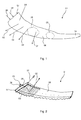
- the luminance image of an in Fig. 1 and Fig. 2 The light guide 01 according to the prior art, which is provided for generating a signal function or a design function in a motor vehicle tail lamp and whose light extraction is achieved in one or more with a desired signal direction preferred direction 02 by means of total reflective prism surfaces 03 appears to be generally inhomogeneous.
- the well-defined prism surfaces 03 used to a certain extent provide a homogeneous luminance distribution of the coupling of at least one light input surface 07 into the light guide 01 coupled light 08 at least one light source 09 on a light output surface 06 of the light guide 01, located in makes one or more homogeneous areas 04 noticeable, but local luminance concentrations arise, which are caused by the prism edges or by an over the cross section of the light guide 01 occurring increased or decreased luminous flux of the angle-dependent Lichteinkopplung by the light source 09, extending through one or more inhomogeneous areas 05 notice.
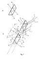
- the optical waveguide 10 has at least one different from the at least one light coupling surface 12, for example at least part of an optical waveguide front side 13
- the light guide 10 comprises at least one of the at least one light output surface 14 different, for example, at least a portion of a light guide back side 15 forming Lichtumlenk Chemistry 16th
- the at least one first Lichtleiterauskoppel Design-part 30 comprises at least partially at least one prism structure 31, by means of the at least one Lichteinkoppel products 12 coupled into the light guide 10 light 11 targeted in at least one direction 51 deflected to the light outcoupling surface 14 and at the light outcoupling surface 14 with refraction at the transition from the optical waveguide material 17 to the surrounding medium 60, which is typically air, is decoupled in at least one preferred direction 50 while maintaining a predetermined luminance ( Fig. 6 ).
- the at least one second Lichtleiterauskoppel Modell-part 40 comprises at least one diffuser structure 41, deflected by means of coupled into the light guide 10 at least one light input surface 12 light 11 with a statistical distribution and at the light outcoupling surface 14 with refraction in the transition from the light guide material to the surrounding medium 60th is diffusely decoupled.
- the diffuser structure 41 comprises at least one optically ineffective surface 42. This can be designed, for example, roughened in a targeted manner in order to effect a particularly good scattering of the light 11 striking it.
- the prism structure 31 has at least one in accordance with the light distribution in at least one preferred direction 50 and the luminance in the at least one preferred direction 50 comprehensive photometric requirements defined effective surface 33 at least one prism element 32 on ( Fig. 7 ).
- a prism element 32 is preferably a structure having one or more active surfaces 33 which effect an internal total reflection in the light guide 10.
- a prism structure 31 comprising one or more such prism elements 32 is also referred to as a totally reflecting prism structure.
- An active surface 33 is a surface of a prismatic element 32 which effects a deflection of the light 11 coupled into the optical waveguide 10 in a direction 51 towards the light exit surface 14, in accordance with the lighting requirements, so that the light 11, which is deflected in such a way under refraction at the transition from the light guide material to a light source 10 surrounding medium 60 in a preferred direction 50 from the light exit surface 14 from the light guide 10 exits.
- the active surface 33 thus differs from a photometric ineffective surface 42 comprising, for example, an end face 34 of a prism element 32 of the prism structure 31 in that, if at all, only a small portion of the light 11 is incident at random, according to a statistical distribution in one corresponding direction 51 is deflected.
- a deflection in one or more directions 52 subject to a statistical distribution takes place at a light-technical ineffective surface 42, which result in an exit of the light 11 in a direction other than a preferred direction 50.
- a deflection in a direction 51 which causes an exit in the preferred direction 50 is purposefully designed and achieved by position and orientation and affects most of the light 11 impinging on it, preferably the entire part.
- the second optical fiber outcoupling structure part 40 may comprise one or more photometrically ineffective surfaces or ineffective surfaces 42 for the light distribution in the at least one preferred direction 50, such as one or more end faces 34 of the prism elements 32 of the prismatic structure 31.
- the second Lichtleiterauskoppel Design-partie 40 between in the extension direction along a central axis 18, for example, a rod-shaped light guide 10 and / or transverse to the extension direction, for example, a Rod-shaped light guide 10 adjacent prism elements 32 lying surface portions 43 include.
- These surface portions 43 like the previously mentioned by way of example mentioned end faces 34 of the prism elements can be roughened or provided with a predetermined surface roughness.
- a central axis 18 can be defined, for example, as a continuous or unsteady mathematical curve on which the centers of gravity of all successive cross-sectional areas of the light guide lie. From this possible discontinuity, there is the possibility that the optical waveguide 10 has different central axes 18 in successive sections, so that in the following at least one central axis 18 is mentioned.
- Fig. 5 and Fig. 6 have the same and / or different dimensions and / or same and / or different geometries in and / or transverse to at least one central axis 18 of the light guide 10.
- Adjacent prism elements 32 of the prism structure 31 of the first light guide outcoupling structure part 30 can, as in FIG Fig. 5 represented different widths and / or as in Fig. 8e) shown differently high and / or as in Fig. 8b) be formed on its front and / or back differently inclined, for example, on a light guide rear side 15 standing up.
- adjacent prism elements 31 may have different orientations relative to a central axis 18 of, for example, rod-shaped optical waveguide 10.
- the prism structure 31 can, as in Fig. 8h) illustrated pyramidal prism elements 32, so-called dots 35, with all sides rising and hitting in a peak lateral surfaces 36 include. Of these lateral surfaces 36, one, several or all photometrically active effective surfaces 33 may include, whereas the remaining lateral surfaces 36 may be technically ineffective surfaces 42.
- the prism structure 31 may alternatively or additionally as in Fig. 8 a), Fig. 8 b) and Fig. 8 c) illustrated sawtooth prism elements 31 with only two line-shaped adjoining photometrically effective active surfaces 33 and these two-sided final, end surfaces 34 forming photometrically ineffective surfaces 42nd include. For example, this can be done as in Fig. 8b) indicated end faces 34 of the prism elements 32 may be specifically provided with a surface roughness.
- the prismatic structure 31 can comprise prism elements 32 which run over the entire width of the light guide 10 and extend over the entire width of the light guide 10.
- the effective photometrically active surfaces 33 of the prism elements 32 as well as the photometrically ineffective, for example, end faces 34 of the prism elements comprehensive surfaces 42 as in Fig. 8d), Fig. 8e) Fig. 8f), Fig. 8g) and Fig. 8h) be shown concave and / or convex at least partially partially sections.
- these may correspond to a portion of a lateral surface 38 of a straight cylinder having a circular or elliptical base as in Fig. 8g) be shown curved cylindrical.
- the light guide 10 may, as in FIG. 3 and FIG. 4 be executed rod-shaped.
- at least one end face 17 forms at least one light coupling surface 12.
- the end face 17 connects the light guide front side 13 extending along at least one central axis 18 of the light guide 10 and including at least one light coupling surface 14 with the at least one central axis 18 of the light guide 10 and at least
- the light guide 10 may have a curved at least in a plane course of its at least one central axis 18.
- the length 19 of a prism element 32 along the prism edge 39 may be in the same orientation of the prism edge 39 in an optimal ratio to the gap length or to the extension 21 of a subsequent surface section 43.
- the invention provides for homogenizing the luminance appearance of a light guide 10 with decoupling prismatic structure 31, the splitting of the prism elements 32 in the prior art, all of them in the form of full peaks 37, into individual pieces along the prism edge 39 (FIG. Fig. 6 . Fig. 7 ) is proposed.
- the prism elements of a light deflection surface 16, ie the active surfaces 33 of the prism elements 32, which are designed so that they reflect the light 11 in a desired preferred direction 50, are now no longer or at least not completely executed as full peaks 37, but in their serrated longitudinal direction along the Prism edge 39 divided into smaller prism elements 32 with spaces.
- the shape of these surfaces 42, which are optically ineffective for the directed deflection can deviate from the flatness; for example, they can be concave or convex in order to adapt the scattering behavior.
- This splitting into individual prisms can take place only locally-if required-as well as over the entire region of the light deflection surface 16 opposite the light output surface 14 of the light guide 10. Depending on which area of the serrated surface is split, or whether the distances between the individual prisms are chosen regularly or irregularly, a more statistically influenced or a more regular structure can be created. It is also possible to alternate areas with directionally deflecting tooth structure as well as the derived diffuser structure, or else in each case be provided exclusively.
- the shape of the active surfaces 33 of an original prism or of a subprism can also be converted into a nonplanar surface, for example into a cylindrical surface, and thus be converted into a rather optically ineffective surface 42 (FIG. Fig. 8b) ).
- the invention is particularly in the field of production of optical fibers and light sources for motor vehicle lights and the production of motor vehicle lights even commercially applicable.
Abstract
Description
Die Erfindung betrifft einen Lichtleiter gemäß dem Oberbegriff des Anspruchs 1, ein Leuchtmittel umfassend einen solchen Lichtleiter gemäß dem Oberbegriff des Anspruchs 9 sowie eine Kraftfahrzeugleuchte mit mindestens einem zuvor genannten Leuchtmittel gemäß dem Oberbegriff des Anspruchs 10.The invention relates to a light guide according to the preamble of
Eine Kraftfahrzeugleuchte umfasst im Wesentlichen einen von einem Leuchtengehäuse und einer Lichtscheibe umschlossenen Leuchteninnenraum und mindestens ein darin beherbergtes Leuchtmittel für wenigstens eine Lichtfunktion der Kraftfahrzeugleuchte. In dem Leuchteninnenraum kann mindestens ein hinter wenigstens einem Teil eines Leuchtmittels, beispielsweise hinter wenigstens einer Lichtquelle des zumindest einem Leuchtmittels, angeordneter Reflektor untergebracht sein. Der Reflektor kann zumindest zum Teil durch ein separates Bauteil und/oder durch wenigstens einen Teil des Leuchtengehäuses selbst, beispielsweise vermittels einer zumindest teilweisen reflektierenden Beschichtung, gebildet sein.A motor vehicle lamp essentially comprises a lamp housing enclosed by a lamp housing and a lens, and at least one lamp housed therein for at least one light function of the motor vehicle lamp. At least one reflector arranged behind at least one part of a luminous means, for example behind at least one light source of the at least one luminous means, can be accommodated in the luminaire interior. The reflector can be formed at least in part by a separate component and / or by at least one part of the luminaire housing itself, for example by means of an at least partially reflective coating.
Wenigstens einer Lichtquelle des Leuchtmittels können ein oder mehrere Optikelemente, wie etwa mindestens eine Linse, mindestens ein Rinnenkonzentrator, z.B. mindestens eine Parabolrinne (CPC; Compound Parabolic Concentrator) oder dergleichen zur Ausformung einer definierten Abstrahlcharakteristik zugeordnet sein.At least one light source of the illuminant may comprise one or more optical elements, such as at least one lens, at least one channel concentrator, e.g. at least one parabolic trough (CPC) or the like for forming a defined emission characteristic.
Die Lichtscheibe ist durch eine transparente Abdeckung gebildet, welche den Leuchteninnenraum sowie die von diesem beherbergten Bauteile gegen Witterungseinflüsse schützt.The lens is formed by a transparent cover, which protects the interior of the lamp and the components housed by this against the weather.
In dem Leuchteninnenraum kann im Strahlengang zwischen wenigstens einer Lichtquelle des Leuchtmittels und der Lichtscheibe wenigstens eine Optikscheibe angeordnet sein, welche beispielsweise eine bestimmte Struktur und/oder Maskierung aufweisen kann, etwa um bei einer klaren, beispielsweise für einen Betrachter eine Tiefenwirkung bewirkenden Lichtscheibe das Leuchtmittel und/oder dessen mindestens eine Lichtquelle zu kaschieren. Das Leuchtengehäuse bzw. der Leuchteninnenraum kann in mehrere Kammern mit jeweils eigenen Lichtquellen und/oder Leuchtmitteln, eventuell Reflektoren und/oder Optikelementen und/oder Optikscheiben, sowie gegebenenfalls Lichtscheiben unterteilt sein, von denen mehrere Kammern gleiche oder jede Kammer eine andere Lichtfunktionen erfüllen kann.In the luminaire interior, at least one optical disk can be arranged in the beam path between at least one light source of the luminous means and the light disk, which can have a specific structure and / or masking, for example, with a clear lens, for example a light effect for a viewer, the luminous means and / or its at least one light source to conceal. The luminaire housing or the luminaire interior can be divided into several chambers, each with its own light sources and / or light sources, possibly reflectors and / or optical elements and / or optical discs, as well as optionally Lenses be divided, of which several chambers can be the same or each chamber can fulfill a different lighting functions.
Bei einer Lichtfunktion handelt es sich dabei um eine zur Erfüllung einer Aufgabe vorgesehene Funktion der Kraftfahrzeugleuchte. Jede Kraftfahrzeugleuchte erfüllt je nach Ausgestaltung eine oder mehrere Aufgaben bzw. Funktionen. Zur Erfüllung jeder Aufgabe bzw. Funktion ist eine Lichtfunktion der Kraftfahrzeugleuchte vorgesehen. Lichtfunktionen sind beispielsweise bei einer Ausgestaltung als Scheinwerfer eine die Fahrbahn ausleuchtende Funktion, oder bei einer Ausgestaltung als Signalleuchte eine Signalfunktion, wie beispielsweise eine Wiederholblinklichtfunktion zur Fahrtrichtungsanzeige oder eine Bremslichtfunktion zur Anzeige einer Bremstätigkeit, oder z.B. einer Begrenzungslichtfunktion, wie etwa einer Rücklichtfunktion, zur Sicherstellung einer Sichtbarkeit des Kraftfahrzeugs bei Tag und/oder Nacht, wie etwa bei einer Ausgestaltung als Heckleuchte oder Tagfahrleuchte. Beispiele für Kraftfahrzeugleuchten sind am Fahrzeugbug, an den Fahrzeugflanken und/oder an den Seitenspiegeln sowie am Fahrzeugheck angeordnete Wiederholblinkleuchten, Ausstiegsleuchten, beispielsweise zur Umfeldbeleuchtung, Begrenzungsleuchten, Bremsleuchten, Nebelleuchten, Rückfahrleuchten, sowie typischerweise hoch gesetzte dritte Bremsleuchten, so genannte Central, High-Mounted Braking Lights, Tagfahrleuchten, Scheinwerfer und auch als Abbiege- oder Kurvenlicht verwendete Nebelscheinwerfer, sowie Kombinationen hiervon.A light function is a function of the motor vehicle light intended to fulfill a task. Each motor vehicle light fulfills one or more tasks or functions depending on the design. To fulfill each task or function, a light function of the motor vehicle light is provided. Light functions are, for example, in a configuration as a headlamp a function illuminating the road surface, or in a configuration as a signal light, a signal function, such as a Wiederblinklichtfunktion to the direction indicator or a brake light function to indicate a braking action, or. a limiting light function, such as a taillight function, to ensure visibility of the vehicle during the day and / or night, such as in a taillight or daytime running light configuration. Examples of motor vehicle lights are the Fahrzeugbug, on the vehicle flanks and / or on the side mirrors and arranged at the rear of vehicle rear lights, exit lights, for example, ambient lighting, marker lights, brake lights, fog lamps, reversing lights, and typically high set third brake lights, so-called Central, High-Mounted Braking lights, daytime running lights, headlamps and fog lights used as turning or cornering lights, as well as combinations thereof.
Ein Leuchtmittel für wenigstens eine Lichtfunktion umfasst zumindest wenigstens eine Lichtquelle, beispielsweise mindestens eine Glühlampe oder mindestens eine Gasentladungslampe oder mindestens eine Leuchtdiode sowie gegebenenfalls Kombinationen hiervon.A luminous means for at least one light function comprises at least at least one light source, for example at least one incandescent lamp or at least one gas discharge lamp or at least one light-emitting diode and optionally combinations thereof.
Beispielsweise kommen als Lichtquellen von Leuchtmitteln für Kraftfahrzeugleuchten unter anderem wegen ihres geringen Stromverbrauchs vermehrt Leuchtdioden zum Einsatz. Diese bestehen aus mindestens einem Lichtemittierende-Diode-Halbleiter-Chip, kurz LED-Chip, sowie wenigstens einer beispielsweise durch Spritzgießen angeformten, den mindestens einen LED-Chip ganz oder teilweise umhüllenden Primäroptik. Auch sind Kraftfahrzeugleuchten bekannt, in denen reine LED-Chips ohne angeformte Primäroptiken zum Einsatz kommen. Im Folgenden wird deshalb der Einfachheit halber nicht mehr zwischen Leuchtdiode und LED-Chip unterschieden und statt dessen einheitlich der Begriff LED stellvertretend für beide Ausgestaltungen verwendet, es sei denn, es ist explizit etwas anderes erwähnt. Herausragende Eigenschaften von LEDs im Vergleich zu anderen, konventionellen Lichtquellen von Leuchtmitteln sind eine wesentlich längere Lebensdauer und eine wesentlich höhere Lichtausbeute bei gleicher Leistungsaufnahme. Dadurch und unter anderem auch wegen ihrer kompakteren Abmessungen können durch Verwendung von LEDs als Lichtquelle von Leuchtmitteln besonders kompakte Kraftfahrzeugleuchten verwirklicht werden, die an fast jede nur erdenkliche Einbausituation angepasst sein können.For example, come as light sources of lamps for automotive lighting, inter alia, because of their low power consumption LEDs increasingly used. These consist of at least one light-emitting diode semiconductor chip, short LED chip, as well as at least one, for example, molded by injection molding, the at least one LED chip completely or partially enveloping primary optics. Also, automotive lights are known in which pure LED chips are used without molded primary optics. In the following, therefore, for the sake of simplicity, no distinction is made between light-emitting diode and LED chip and instead, the term LED is used uniformly for both embodiments, unless explicitly stated otherwise. Outstanding properties of LEDs compared to other, conventional light sources of bulbs are a much longer life and a significantly higher light output with the same power consumption. As a result, and among other things also because of their more compact dimensions can be realized by using LEDs as a light source of light bulbs particularly compact automotive lights, which can be adapted to almost every imaginable installation situation.
Darüber hinaus können bei einer Kraftfahrzeugleuchte ein oder mehrere Lichtleiter vorgesehen sein, beispielsweise um eine gewünschte Lichtverteilung z.B. über die Lichtscheibe hinweg des von einer oder mehreren Lichtquellen ausgestrahlten Lichts zu erhalten.In addition, in a motor vehicle light, one or more optical fibers may be provided, for example to provide a desired light distribution e.g. across the lens of the light emitted by one or more light sources.
Ein Lichtleiter, in den Licht mindestens einer Lichtquelle an mindestens einer Lichteinkoppelfläche ein- und an mindestens einer von der Lichteinkoppelfläche verschiedenen Lichtauskoppelfläche wieder ausgekoppelt wird, kann dabei als ein separates Bauteil im Leuchteninnenraum beherbergt oder Teil eines Leuchtmittels sein.An optical waveguide in which light is coupled in at least one light source to at least one light coupling surface and coupled back to at least one light coupling surface that is different from the light coupling surface can be accommodated as a separate component in the interior of the luminaire or be part of a light source.
Beispielsweise kann ein Leuchtmittel einen oder mehrere Lichtleiter sowie eine oder mehrere, das von ihnen ausgestrahlte Licht zumindest zum Teil in den wenigstens einen Lichtleiter einkoppelnde Lichtquellen umfassen. Ein Lichtleiter eines solchen Leuchtmittels kann beispielsweise als Primäroptik einer oder mehrerer LEDs dienen bzw. als eine solche Primäroptik ausgebildet sein.By way of example, a luminous means may comprise one or more light guides and one or more light sources emitting light from them, at least in part into the light sources coupling in at least one light guide. An optical waveguide of such a luminous means can serve, for example, as a primary optic of one or more LEDs or be designed as such a primary optic.
Der Lichtleiter kann beispielsweise stabförmig als so genannter Stablichtleiter und/oder flächig als so genannter Flächenlichtleiter ausgebildet sein, mit einer auf seiner beispielsweise normal zur Hauptabstrahlrichtung einer Kraftfahrzeugleuchte orientierten Vorderseite angeordneten Lichtauskoppelfläche.The optical waveguide can be configured, for example, in the form of a bar as a so-called bar light guide and / or as a so-called planar light guide, with a light output surface arranged on its front side oriented, for example, normal to the main emission direction of a motor vehicle light.
Damit das aus einer Lichtauskoppelfläche austretende Licht bei einem solchen Lichtleiter einer bestimmten, bei einer Kraftfahrzeugleuchte gesetzlich vorgegebenen Lichtverteilung in eine oder mehrere Vorzugsrichtungen und Leuchtdichte in dieser einen oder mehreren Vorzugsrichtungen der Lichtauskopplung aus dem Lichtleiter genügt, sind beispielsweise auf einer der Lichtauskoppelfläche gegenüberliegenden Rückseite des Lichtleiters vorgesehene Lichtleiterauskoppelstrukturen mit einer gerichteten Auskopplung des in den Lichtleiter eingekoppelten Lichts in einer oder mehreren Vorzugsrichtungen beispielsweise über die gesamte Länge des Lichtleiters hinweg bekannt.So that the light emerging from a light coupling surface in such a light guide of a certain, prescribed in a motor vehicle light distribution in one or more preferred directions and luminance in this one or more preferred directions of Lichtauskopplung from the light guide are, for example, on one of the light output surface opposite back of the light guide intended Lichtleiterauskoppelstrukturen with a directed Coupling of the coupled into the light guide light in one or more preferred directions, for example, over the entire length of the light guide away known.
Diese Lichtleiterauskoppelstrukturen umfassen eine beispielsweise auf der Lichtleiterrückseite angeordnete, totalreflektierende Prismenstruktur, welche das Licht im Lichtleiter umlenkt und an einer gegenüberliegenden oder angrenzenden Lichtauskoppelfläche unter Brechung beim Übergang vom Lichtleitermaterial zur umgebenden Luft in mindestens einer Vorzugsrichtung unter Einhaltung einer den lichttechnischen Anforderungen in der mindestens einen Vorzugsrichtung genügenden Leuchtdichte auszukoppeln.These light guide outcoupling structures comprise a totally reflecting prism structure arranged, for example, on the light guide backside, which redirects the light in the light guide and on an opposite or adjacent light outcoupling surface with refraction at the transition from the light guide material to the surrounding air in at least one preferred direction while maintaining the lighting requirements in the at least one preferred direction decoupling sufficient luminance.
Dabei kommt es jedoch insbesondere bei gekrümmt verlaufenden Lichtleitern, wie sie insbesondere in Kraftfahrzeugen benötigt werden, um der Form einer in die Außenkontur eines Kraftfahrzeugs eingepassten Lichtscheibe einer Kraftfahrzeugleuchte zu folgen, aufgrund der gezielten Umlenkung in die eine oder mehreren Vorzugsrichtungen zu einer lokal stark inhomogenen Leuchtdichtenverteilung bei der Betrachtung aus einem Betrachtungswinkel. Diese macht sich durch eine mit bloßem Auge wahrnehmbar punktuell unterschiedlichen Helligkeiten im Erscheinungsbild des Lichtleiters bemerkbar. Dies wird als störend und den Qualitätseindruck nachhaltig negativ beeinflussend empfundenen.However, in particular in the case of curved optical waveguides, which are required in particular in motor vehicles in order to follow the shape of a lens of a motor vehicle light fitted in the outer contour of a motor vehicle, due to the targeted deflection into the one or more preferred directions, a locally highly inhomogeneous luminance distribution occurs when viewed from a viewing angle. This is noticeable by a perceptible with the naked eye selectively different brightnesses in the appearance of the light guide. This is perceived as disturbing and the quality impression sustainably negatively influencing.
Um ein homogenes Erscheinungsbild zu erhalten, welches frei von punktuell unterschiedlichen Helligkeiten ist, ist bekannt, Auskoppelstrukturen vorzusehen, die jedoch keine definierte Auskopplung in einer Vorzugsrichtung zulassen. Beispiele hierfür sind Diffusor-Strukturen, welche auf einer ungerichteten Ablenkung des Lichts an mikroskopisch kleinen, typischerweise auf einer der Lichtauskoppelfläche gegenüberliegenden Lichtleiterrückseite vorgesehenen Flächen beruhen. Solche Diffusor-Strukturen werden beispielsweise durch eine gezielte, jedoch einer statistischen Verteilung unterliegende Oberflächenrauigkeit erhalten.In order to obtain a homogeneous appearance, which is free of pointwise different brightnesses, it is known to provide coupling-out structures which, however, do not permit a defined coupling-out in a preferred direction. Examples of these are diffuser structures, which are based on an undirected deflection of the light at microscopically small areas, which are typically provided on an optical waveguide rear side opposite the light outcoupling surface. Such diffuser structures are obtained for example by a targeted, but a random distribution subject surface roughness.
Nachteilig hieran ist, dass mit solchen Diffusor-Strukturen keine gezielte Auskopplung in einer oder mehreren beispielsweise durch gesetzliche Vorgaben definierten Vorzugsrichtungen möglich ist. Um demnach bei einer solchen, ein homogenes Erscheinungsbild aufweisenden Diffusor-Struktur beispielsweise gesetzliche Vorgaben durch Einhaltung eines den lichttechnischen Anforderungen in Vorzugsrichtung genügenden Leuchtdichte zu erfüllen, muss eine wesentlich höhere Lichtstrahlungsleistung bzw. ein wesentlich höherer Lichtstrom in den Lichtleiter eingekoppelt werden, was einerseits einen hohen Bauraumbedarf zur Folge hat, andererseits aufgrund der hierfür erforderlichen stärkeren und/oder mehreren Lichtquellen höhere Kosten nach sich zieht und außerdem zu einem unnötig hohen Stromverbrauch einhergehend mit einer stärkeren Belastung und damit Auslegung des Bordnetzes eines Kraftfahrzeugs führt. Außerdem kann vermittels Diffusor-Strukturen der entlang des Lichtleiters lokal ausgekoppelte Lichtstrom nicht gut oder gar nicht gesteuert werden, was jedoch notwendig ist, um beispielsweise auch Endbereiche eines Lichtleiters hell erscheinen zu lassen.The disadvantage of this is that with such diffuser structures no targeted decoupling in one or more preferred directions defined for example by legal requirements is possible. Accordingly, in such a diffuser structure having a homogeneous appearance, for example, legal specifications by observing a lighting requirements in the preferred direction To meet sufficient luminance, a much higher light radiation power or a significantly higher luminous flux must be coupled into the optical fiber, which on the one hand has a high space requirement result, on the other hand, due to the required stronger and / or multiple light sources higher costs and also to an unnecessarily high power consumption associated with a greater burden and thus interpretation of the electrical system of a motor vehicle leads. In addition, by means of diffuser structures, the luminous flux locally coupled out along the optical waveguide can not be controlled well or not at all, which is necessary, however, in order, for example, to make end regions of an optical waveguide appear bright.
Darüber hinaus ist bekannt, eine totalreflektierende Prismenstruktur mit wohldefinierten Prismenelementen auf einer der Lichtauskoppelfläche gegenüberliegenden Lichtleiterrückseite vorzusehen, und an der Lichtauskoppelfläche Diffusor-Strukturen mit einer statistischen Verteilung der Wirkelemente, beispielsweise zusätzliche Deckelemente mit rauer Oberfläche, und/oder eine oder mehrere diffus reflektierende Umgebungsflächen des Lichtleiters vorzusehen.In addition, it is known to provide a totally reflecting prism structure with well-defined prism elements on one of the light output surface opposite light guide back, and at the light output surface diffuser structures with a statistical distribution of the active elements, such as additional cover elements with rough surface, and / or one or more diffusely reflective surrounding surfaces of the Provide light guide.
Außerdem sind Lichtleiter mit einer glatten Lichtleiterrückseite und einer rauen Frontfläche als Auskoppelfläche bekannt.In addition, light guides with a smooth optical fiber back and a rough front surface are known as decoupling surface.
Auch diese Maßnahmen genügen nicht, um die geschilderten Nachteile zumindest ansatzweise zu lösen.These measures are not sufficient to solve the disadvantages described at least rudimentary.
Zur Hintergrundbeleuchtung von LCD-Displays ist ferner bekannt, eine regelmäßige Auskoppelstruktur vorzusehen, welche eine Vorzugsrichtung der Lichtauskopplung normal zur Vorderseite des LCD-Displays bewirkt. Deren Verwendung bei Kraftfahrzeugleuchten scheitert jedoch am im Raum dreidimensional gekrümmten Verlauf von Lichtleitern in Kraftfahrzeugleuchten und der damit aus Sicht des Lichtleiters mit der Krümmung lokal veränderlichen Vorzugsrichtung.For backlighting of LCD displays is also known to provide a regular coupling-out structure, which causes a preferred direction of light extraction normal to the front of the LCD display. Their use in motor vehicle lights, however, fails because of the three-dimensionally curved course of light guides in motor vehicle lights in the room and thus with the curvature locally variable preferred direction from the perspective of the light guide.
Durch
Nachteilig hieran ist neben dem komplexen Aufbau, dass wenn mehrere Vorzugsrichtungen mit einem solchen Lichtleiterelement verwirklicht werden sollen, keine homogene Leuchtdichtenverteilung erhalten werden kann. Darüber hinaus ist das Lichtleiterelement nicht geeignet, einem gekrümmten Verlauf einer Lichtscheibe zu folgen.The disadvantage of this, in addition to the complex structure, that when several preferred directions are to be realized with such a light guide element, no homogeneous luminance distribution can be obtained. In addition, the light guide element is not suitable to follow a curved course of a lens.
Durch
Nachteilig hieran ist, dass für einen Betrachter die gewölbten Lichtauskoppelflächenpartien nur in denjenigen Bereichen hell erscheinen, in denen Licht in seine Richtung austritt. Damit wird weder eine für den Betrachter homogene Leuchtdichtenverteilung erhalten, noch ist das Lichtleiterelement aufgrund seines sehr komplizierten Aufbaus in Verbindung mit der Vielzahl der rechtwinkligen Lichtumlenkungen zur Anpassung an einen gekrümmten Verlauf einer Lichtscheibe geeignet.The disadvantage of this is that for a viewer, the curved Lichtauskoppelflächenpartien appear bright only in those areas in which light exits in his direction. Thus, neither a homogeneous distribution of luminance for the viewer is obtained, nor is the light guide element due to its very complicated structure in conjunction with the plurality of rectangular light deflections suitable for adaptation to a curved course of a lens.
Durch
Nachteilig hieran ist, dass wenn mehrere Vorzugsrichtungen mit einem solchen Lichtleiterelement verwirklicht werden sollen, keine homogene Leuchtdichtenverteilung erhalten werden kann. Darüber hinaus ist das ebene Lichtleiterelement nicht geeignet, einem gekrümmten Verlauf einer Lichtscheibe zu folgen.The disadvantage of this is that when several preferred directions are to be realized with such a light guide element, no homogeneous luminance distribution can be obtained. In addition, the planar light guide element is not suitable to follow a curved course of a lens.
Durch
Nachteilig hieran ist, dass der gerade, stabförmige Lichtleiter über seine gesamte Länge eine identische Vorzugsrichtung der Lichtauskopplung in Bezug auf die Lichtauskoppelfläche aufweist. Wird der stabförmige Lichtleiter gekrümmt angeordnet, verändert sich diese Vorzugsrichtung mit der sich durch die Krümmung verändernden lokalen Orientierung der Lichtaustrittsfläche des Lichtleiters. Eine Erfüllung gesetzlicher Vorgaben bezüglich Lichtverteilung und Leuchtdichte ist damit nur durch eine entsprechende Erhöhung der eingekoppelten Lichtstärke möglich, einhergehend mit den Eingangs erwähnten Nachteilen eines hohen Bauraumbedarfs für die entsprechend stark dimensionierte mindestens eine Lichtquelle, der höheren Kosten aufgrund der hierfür erforderlichen stärkeren und/oder mehreren Lichtquellen, sowie des unnötig hohen Stromverbrauchs einhergehend mit einer stärkeren Belastung und damit Auslegung des Bordnetzes eines Kraftfahrzeugs. Darüber hinaus scheint jeweils nur der mit der Prismenstruktur hinterlegte Teil der Lichtauskoppelfläche aus Richtung der Vorzugsrichtung gesehen hell. Verbleibende Teile, beispielsweise solche, in denen sich die Prismen nur über einen Teil der Breite der Lichtleiterrückseite erstrecken erschenen demgegenüber dunkel. Dadurch weist der Lichtleiter zwar über seine Länge messtechnisch homogene Leuchtdichte in Vorzugsrichtung auf, erscheint jedoch insbesondere bei einem gekrümmten Verlauf über seine Länge hinweg unterschiedlich hell sowie in seiner Breite unterschiedlich ausgeleuchtet.The disadvantage of this is that the straight, rod-shaped light guide over its entire length has an identical preferred direction of light extraction with respect to the light output surface. If the rod-shaped optical waveguide is arranged curved, this preferred direction changes with the local orientation of the light exit surface of the optical waveguide which changes as a result of the curvature. Compliance with legal requirements regarding light distribution and luminance is thus possible only by a corresponding increase in the coupled light intensity, along with the aforementioned disadvantages of a high space requirement for the correspondingly sized at least one light source, the higher cost due to the stronger and / or more required for this Light sources, as well as the unnecessarily high power consumption associated with a higher load and thus design of the electrical system of a motor vehicle. In addition, only the part of the light outcoupling surface deposited with the prismatic structure from the direction of the preferential direction appears bright in each case. Remaining parts, for example those in which there are the prisms extend only over part of the width of the light guide back erschenen contrast dark. As a result, although the optical waveguide has metrologically homogeneous luminance in the preferred direction over its length, it appears to be of different brightness and differently illuminated in its width, in particular in the case of a curved course over its length.
Der Erfindung liegt die Aufgabe zu Grunde, einen Lichtleiter, ein Leuchtmittel mit einem Lichtleiter und eine Kraftfahrzeugleuchte mit einem einen Lichtleiter umfassenden Leuchtmittel zu entwickeln, welche eine Lichtauskopplung in einer oder mehreren, in ihrer Orientierung zu einer lokalen Flächennormale einer Lichtauskoppelfläche verschiedenen Vorzugsrichtungen bei gleichzeitig homogener Leuchtdichtenverteilung aufweisen.The invention is based on the object to develop a light guide, a light source with a light guide and a motor vehicle light with a light guide comprising bulbs, which light extraction in one or more, in their orientation to a local surface normal light extraction surface different preferred directions at the same time homogeneous Have luminance distribution.
Die Aufgabe wird jeweils gelöst mit den Merkmalen der unabhängigen Ansprüche.The object is achieved in each case with the features of the independent claims.
Ein erster Gegenstand der Erfindung betrifft demnach einen beispielsweise stabförmigen, vorzugsweise beispielsweise in einer Ebene und/oder besonders bevorzugt dreidimensional im Raum gekrümmt verlaufenden Lichtleiter mit mindestens einer Lichteinkoppelfläche, mindestens einer von der wenigstens einen Lichteinkoppelfläche verschiedene Lichtauskoppelfläche, sowie wenigstens eine von der zumindest einen Lichtauskoppelfläche verschiedene Lichtumlenkfläche. Die mindestens eine Lichtumlenkfläche ist bevorzugt auf wenigstens einer der zumindest einen Lichtauskoppelfläche gegenüberliegenden Lichtleiterrückseite angeordnet oder von einer solchen umfasst oder umfasst eine solche.A first subject of the invention accordingly relates to a light guide, for example of a rod, preferably curved in a plane and / or particularly preferably three-dimensionally in space with at least one light coupling surface, at least one light coupling surface different from the at least one light coupling surface, and at least one of the at least one light coupling surface different light deflection surface. The at least one light deflection surface is preferably arranged on at least one light guide rear side opposite the at least one light output surface or comprises or comprises such.
Mindestens eine Lichtumlenkfläche ist mit einer Hybrid-Lichtleiterauskoppelstruktur versehen. Die Hybrid-Lichtleiterauskoppelstruktur besteht aus mindestens einer ersten Lichtleiterauskoppelstruktur-Partie und wenigstens einer an zumindest eine erste Lichtleiterauskoppelstruktur-Partie angrenzenden zweiten Lichtleiterauskoppelstruktur-Partie.At least one Lichtumlenkfläche is provided with a hybrid Lichtleiterauskoppelstruktur. The hybrid Lichtleiterauskoppelstruktur consists of at least a first Lichtleiterauskoppelstruktur-lot and at least one adjacent to at least a first Lichtleiterauskoppelstruktur-part second Lichtleiterauskoppelstruktur-Lotie.
Die mindestens eine erste Lichtleiterauskoppelstruktur-Partie umfasst vorzugsweise zumindest zum Teil wenigstens eine beispielsweise totalreflektierende Prismenstruktur, vermittels der in den Lichtleiter an wenigstens einer Lichteinkoppelfläche eingekoppeltes Licht gezielt in einer oder mehreren Richtungen zur Lichtauskoppelfläche hin umgelenkt und an der Lichtauskoppelfläche unter Brechung beim Übergang vom Lichtleitermaterial zum umgebenden Medium, beispielsweise zur umgebenden Luft, in wenigstens einer Vorzugsrichtung unter Einhaltung einer beispielsweise gesetzlich vorgegebenen lichttechnischen Anforderungen an eine Kraftfahrzeugleuchte in einer oder mehreren Vorzugsrichtungen genügenden Leuchtdichte ausgekoppelt wird. Die Vorzugsrichtungen sind dabei durch eine ebenfalls beispielsweise gesetzlich vorgegebene Lichtverteilung definiert.The at least one first Lichtleiterauskoppelstruktur-lot preferably comprises at least partially at least one example total reflecting prism structure, by means of coupled into the light guide at least one Lichteinkoppeles light specifically deflected in one or more directions to the light outcoupling surface and at the light outcoupling surface under refraction in the transition from the light guide material to surrounding medium, for example to the surrounding air, in at least one preferred direction in compliance with a legally prescribed, for example, lighting requirements for a motor vehicle light in one or more preferred directions sufficient luminance is coupled. The preferred directions are defined by a likewise, for example, legally prescribed light distribution.
Die mindestens eine an zumindest eine erste Lichtleiterauskoppelstruktur-Partie angrenzende zweite Lichtleiterauskoppelstruktur-Partie umfasst vorzugsweise wenigstens eine Diffusor-Struktur, vermittels der in den Lichtleiter an wenigstens einer Lichteinkoppelfläche eingekoppeltes Licht mit einer statistischen Verteilung umgelenkt und an der Lichtauskoppelfläche unter Brechung beim Übergang vom Lichtleitermaterial zum umgebenden Medium diffus ausgekoppelt wird.The at least one adjoining at least a first Lichtleiterauskoppelstruktur-part second Lichtleiterauskoppelstruktur-lot preferably comprises at least one diffuser structure, deflected by means of coupled into the light guide at least one Lichteinkoppeles light with a random distribution and at the light outcoupling surface under refraction in the transition from the optical fiber material to surrounding medium is diffusely decoupled.
Die Prismenstruktur umfasst vorzugsweise wenigstens eine gemäß den die Lichtverteilung in einer oder mehreren Vorzugsrichtungen sowie die Leuchtdichte in der mindestens einen Vorzugsrichtung umfassenden lichttechnischen Anforderungen definierte Wirkfläche zumindest eines Prismenelements.The prism structure preferably comprises at least one effective surface of at least one prism element defined according to the lighting requirements in one or more preferred directions and the luminance in the at least one preferred direction.
Bei dem Prismenelement handelt es sich bevorzugt um eine Struktur mit einer oder mehreren eine interne Totalreflexion im Lichtleiter bewirkenden Wirkflächen. Eine ein oder mehrere solche Prismenelemente umfassende Prismenstruktur kann auch als totalreflektierende Prismenstruktur bezeichnet werden.The prism element is preferably a structure having one or more effective internal surfaces causing total internal reflection in the light guide. A prism structure comprising one or more such prism elements can also be called a totally reflecting prism structure.
Die Prismenstruktur stellt damit die Einhaltung der lichttechnischen Anforderungen sicher.The prism structure thus ensures compliance with lighting requirements.
Die Diffusor-Struktur umfasst wenigstens eine Fläche mit einer beispielsweise durch eine gezielte, jedoch einer statistischen Verteilung unterliegende Oberflächenrauigkeit erhaltenen statistischen Verteilung der die diffuse Auskopplung ursächlich bewirkenden statistisch verteilten Umlenkung verursachenden Wirkelemente. Bei den Wirkelementen handelt es sich beispielsweise um das Licht umlenkende, kleine Flächenabschnitte mit Abmessungen in der Dimension der Oberflächenrauigkeit.The diffuser structure comprises at least one surface with a statistical distribution of the active elements which cause the diffuse decoupling which causes the diffuse decoupling, for example, by means of a targeted surface roughness subject to a statistical distribution. The active elements are, for example, light-deflecting, small surface sections with dimensions in the dimension of the surface roughness.
Die Diffusor-Struktur stellt damit den Erhalt eines homogenen Eindrucks des Lichtleiters für den Betrachter aus unterschiedlichen Richtungen sicher.The diffuser structure thus ensures that a homogeneous impression of the light guide for the viewer from different directions.
Die zweite Lichtleiterauskoppelstruktur-Partie kann eine oder mehrere lichttechnisch unwirksame bzw. für die Lichtverteilung in der mindestens einen Vorzugsrichtung unwirksame Flächen, wie etwa eine oder mehrere Stirnflächen der Prismenelemente der Prismenstruktur umfassen. Diese beispielsweise Stirnflächen umfassende Flächen können aufgeraut ausgeführt bzw. mit einer vorgegebenen Oberflächenrauigkeit versehen sein.The second optical fiber extraction structure part may be one or more photometrically ineffective or for the light distribution in the at least one preferred direction ineffective surfaces, such as comprise one or more end faces of the prism elements of the prism structure. These surfaces, for example, comprising faces, can be roughened or provided with a predetermined surface roughness.
Alternativ oder zusätzlich kann die zweite Lichtleiterauskoppelstruktur-Partie zwischen in Erstreckungsrichtung beispielsweise eines stabförmigen Lichtleiters und/oder quer zur Erstreckungsrichtung beispielsweise eines stabförmigen Lichtleiters benachbarten Prismenelementen liegende Flächenabschnitte umfassen. Diese Flächenabschnitte können aufgeraut ausgeführt bzw. mit einer vorgegebenen Oberflächenrauigkeit versehen sein.Alternatively or additionally, the second Lichtleiterauskoppelstruktur-part between extending in the extension direction, for example, a rod-shaped light guide and / or transverse to the extension direction, for example, a rod-shaped light guide prism elements lying surface sections. These surface sections may be executed roughened or provided with a predetermined surface roughness.
Benachbarte Prismenelemente der Prismenstruktur der ersten Lichtleiterauskoppelstruktur-Partie können unterschiedliche breit und/oder unterschiedlich hoch und/oder auf ihrer Vorder- und/oder Rückseite unterschiedlich geneigt beispielsweise auf einer Lichtleiterrückseite aufstehend ausgebildet sein. Alternativ oder zusätzlich können benachbarte Prismenelemente unterschiedliche Orientierungen relativ zu einer Mittelachse des beispielsweise stabförmigen Lichtleiters aufweisen. Die Mittelachse kann dabei beispielsweise definiert sein als stetige oder unstetige mathematische Kurve, auf der die Schwerpunkte aller aufeinander folgender Querschnittsflächen des Lichtleiters liegen.Neighboring prism elements of the prism structure of the first light guide outcoupling structure portion may be formed differently wide and / or differently high and / or differently inclined on their front and / or rear side, for example, standing up on a light guide rear side. Alternatively or additionally, adjacent prism elements may have different orientations relative to a central axis of the, for example, rod-shaped optical waveguide. The central axis can be defined, for example, as a continuous or unsteady mathematical curve on which the centers of gravity of all successive cross-sectional areas of the light guide lie.
Zwischen gegebenenfalls in Richtung entlang der Mittelachse sowie gegebenenfalls alternativ oder zusätzlich quer zu der Mittelachse benachbarten Prismenelementen liegende Flächenabschnitte können gleiche und/oder unterschiedliche Abmessungen und/oder gleiche und/oder unterschiedliche Geometrien in und/oder quer zur Mittelachse des Lichtleiters aufweisen.Between optionally in the direction along the central axis and optionally alternatively or additionally transverse to the central axis adjacent prism elements surface portions may have the same and / or different dimensions and / or same and / or different geometries in and / or transverse to the central axis of the light guide.
Die Prismenstruktur kann pyramidenförmige Prismenelemente, so genannte Dots, mit allseitig sich erhebenden und in einer Spitze treffenden Mantelflächen umfassen. Von diesen Mantelflächen können eine, mehrere oder alle lichttechnisch wirksame Wirkflächen umfassen. Die Prismenstruktur kann alternativ oder zusätzlich sägezahnförmige Prismenelemente mit nur zwei linienförmig aneinander angrenzenden lichttechnisch wirksamen Wirkflächen sowie diese beidseitig abschließenden lichttechnisch unwirksame, Stirnflächen bildende Flächen umfassen. Ebenso kann die Prismenstruktur als sich über die gesamte Breite des Lichtleiters erstreckende Vollzacken ausgeführte Prismenelemente umfassen.The prism structure may comprise pyramid-shaped prism elements, so-called dots, with lateral surfaces rising and striking in a point. Of these lateral surfaces may comprise one, several or all photometrically effective active surfaces. The prism structure may alternatively or additionally comprise sawtooth-shaped prism elements with only two line-like, effective active surfaces which are adjacent to each other in a line, and also surfaces which terminate on both sides and which are ineffective in terms of lighting technology. Likewise, the Prism structure as extending over the entire width of the light guide extending full peaks prism elements comprise.
Die lichttechnisch wirksamen Wirkflächen der Prismenelemente können ebenso wie die lichttechnisch unwirksamen, beispielsweise Stirnflächen der Prismenelemente umfassenden Flächen zumindest teilweise abschnittsweise konkav und/oder konvex gewölbt sein. Beispielsweise können diese entsprechend eines Abschnitts einer Mantelfläche eines geraden Zylinders mit kreis- oder ellipsenförmiger Grundfläche zylinderförmig gewölbt sein.The effective photometrically effective active surfaces of the prism elements, as well as the photometrically ineffective, for example, faces of the prism elements comprehensive surfaces at least partially sectionally concave and / or convex. For example, these may be cylindrically curved in accordance with a portion of a lateral surface of a straight cylinder having a circular or elliptical base.
Wichtig ist hervorzuheben, dass die genannten auf einer wie einleitend zum ersten Gegenstand der Erfindung definierten Lichtumlenkfläche befindlichen lichttechnisch unwirksamen Flächen, welche keinen gezielten Beitrag zur Lichtumlenkung für die Lichtverteilung in der mindestens einen Vorzugsrichtung leisten, der zweiten Lichtleiterauskoppelstruktur-Partie zugeordnet sein können, und vollständig oder teilweise mit einer Diffusor-Struktur versehen sein können. Die Diffusor-Struktur kann beispielsweise durch eine aufgeraute Oberfläche erhalten sein.It is important to emphasize that the mentioned light technically ineffective surfaces, which do not make a specific contribution to the light deflection for the light distribution in the at least one preferred direction, can be assigned to the second optical fiber extraction structure part and completely on a light deflection surface as defined by the first subject of the invention or may be partially provided with a diffuser structure. The diffuser structure may be obtained, for example, by a roughened surface.
Ein zweiter Gegenstand der Erfindung betrifft ein Leuchtmittel mit mindestens einer Lichtquelle und wenigstens einem dieser zugeordneten, zuvor beschriebenen Lichtleiter. In den Lichtleiter wird Licht mindestens einer Lichtquelle an mindestens einer Lichteinkoppelfläche ein- und an mindestens einer von der Lichteinkoppelfläche verschiedenen Lichtauskoppelfläche wieder ausgekoppelt.A second subject of the invention relates to a luminous means with at least one light source and at least one optical waveguide associated therewith and previously described. In the light guide light is at least one light source on at least one light input surface on and coupled out at least one of the light input surface different light outcoupling surface again.
Das Leuchtmittel kann wenigstens eine Lichtemittierende Diode (LED) und/oder einen LED-Chip als Lichtquelle umfassen.The lighting means may comprise at least one light-emitting diode (LED) and / or an LED chip as the light source.
Der Lichtleiter kann an wenigstens eine LED oder wenigstens einen LED-Chip angespritzt sein. In diesem Fall wird die Lichteinkoppelfläche von den jeweils an eine LED bzw. einen LED-Chip unmittelbar anstoßenden Partien des Lichtleiters umfasst.The light guide may be molded onto at least one LED or at least one LED chip. In this case, the light incoupling surface is encompassed by the respective parts of the light guide which abut directly on an LED or an LED chip.
Ein dritter Gegenstand der Erfindung betrifft eine Kraftfahrzeugleuchte mit einem von einem Leuchtengehäuse und einer Lichtscheibe umschlossenen Leuchteninnenraum und mindestens einem darin beherbergten Leuchtmittel für wenigstens eine Lichtfunktion der Kraftfahrzeugleuchte. Das mindestens eine Leuchtmittel umfasst neben wenigstens einer Lichtquelle zumindest einen der wenigstens einen Lichtquelle zugeordneten, zuvor beschriebenen Lichtleiter.A third object of the invention relates to a motor vehicle light with a lamp housing enclosed by a lamp housing and a lens interior and at least one light source housed therein for at least one light function of the motor vehicle light. The at least one luminous means comprises, in addition to at least one light source, at least one of the at least one light source associated previously described light guide.
Die Kraftfahrzeugleuchte kann beispielsweise als Heckleuchte für ein Kraftfahrzeug ausgebildet sein.The motor vehicle light may be formed, for example, as a tail lamp for a motor vehicle.
Es ist ersichtlich, dass die Erfindung durch eine Hybrid-Lichtleiterauskoppelstruktur verwirklicht sein kann, bestehend aus:
- mindestens einer auf wenigstens einer von zumindest einer Lichtauskoppelfläche eines Lichtleiters verschiedenen Lichtumlenkfläche vorgesehenen ersten Lichtleiterauskoppelstruktur-Partie mit wenigstens einem Teil einer totalreflektierenden Prismenstruktur, vermittels welchen Teils Licht im Lichtleiter gezielt in einer oder mehreren Richtungen umgelenkt und an der Lichtauskoppelfläche unter Brechung beim Übergang vom Lichtleitermaterial zur umgebenden Luft in wenigstens einer Vorzugsrichtung unter Einhaltung eines den lichttechnischen Anforderungen in Vorzugsrichtung genügenden Lichtstroms bzw. Leuchtdichte ausgekoppelt wird, sowie
- mindestens einer ebenfalls auf der wenigstens einen von der zumindest einen Lichtauskoppelfläche des Lichtleiters verschiedenen Lichtumlenkfläche vorgesehenen, an zumindest eine erste Lichtleiterauskoppelstruktur-Partie angrenzenden zweiten Lichtleiterauskoppelstruktur-Partie mit wenigstens einer Diffusor-Struktur, vermittels der Licht im Lichtleiter mit einer statistischen Verteilung umgelenkt und an der Lichtauskoppelfläche unter Brechung beim Übergang vom Lichtleitermaterial zur umgebenden Luft diffus ausgekoppelt wird.
- at least one provided on at least one of at least one Lichtauskoppelfläche a light guide Lichtunterlenkfläche first Lichtleiterauskoppelstruktur-lot with at least a portion of a total reflecting prism structure, by means of which part light in the light guide specifically deflected in one or more directions and at the light outcoupling surface under refraction in the transition from the light guide material to surrounding air is coupled in at least one preferred direction while maintaining a luminous flux or luminance sufficient for the lighting requirements in the preferred direction, and
- at least one also on the at least one of the at least one light output surface of the light guide different Lichtumlenkfläche provided, adjacent to at least a first Lichtleiterauskoppelstruktur-part second Lichtleiterauskoppelstruktur-lot with at least one diffuser structure, deflected by means of the light in the light guide with a statistical distribution and at the Lichtauskoppelfläche diffracted at the transition from the light guide material to the surrounding air is diffused coupled.
Vorteile gegenüber dem Stand der Technik ergeben sich unter Anderem durch ein homogenes Erscheinungsbild aus verschiedenen Betrachtungsrichtungen frei von durch das menschliche Auge wahrnehmbaren, unterschiedlichen Helligkeiten unter gleichzeitiger Erfüllung der beispielsweise durch gesetzliche Vorschriften vorgegebenen und die Lichtverteilung in einer oder mehreren Vorzugsrichtungen sowie die Leuchtdichte in der mindestens einen Vorzugsrichtung umfassenden lichttechnischen Anforderungen bei gleichzeitig geringer erforderlicher in den Lichtleiter einzukoppelnder Strahlungsleistung bzw. geringem erforderlichem in den Lichtleiter einzukoppelndem Lichtstrom. Hierdurch wird ein besonders wirtschaftlicher und effektiver Umgang mit der zur Verfügung stehenden Energie erzielt. Bei Kraftfahrzeuganwendungen ergibt sich dadurch eine besonders günstige Auslegung und Dimensionierung des Bordnetzes einhergehend mit einer verbesserten Wirtschaftlichkeit und Gewichtseinsparungen.Advantages over the prior art result, inter alia, by a homogeneous appearance from different viewing directions free from perceptible by the human eye, different brightnesses while fulfilling the example prescribed by law and the light distribution in one or more preferred directions and the luminance in the at least a preferred direction comprehensive lighting requirements at the same time low required einzkoppelnder in the light guide radiation power or low required einzkoppelndem in the light guide luminous flux. As a result, a particularly economical and effective handling of the available energy is achieved. In automotive applications, this results in a particularly favorable design and dimensioning of the electrical system along with improved economy and weight savings.
Die Verknüpfung zwischen diffus wirkenden Licht-Auskoppelelementen der zweiten Lichtleiterauskoppelstruktur-Partie und gerichtet wirkenden Licht-Auskoppelelementen der ersten Lichtleiterauskoppelstruktur-Partie erlaubt eine Abstimmung zwischen lichttechnischer Effizienz bezogen auf die gewünschte Auskoppelrichtung bzw. die mindestens eine Vorzugsrichtung des gesamtem Lichtleiters und dessen homogenen Leuchtdichtebildes einerseits als auch die grundsätzlich steuerbare Homogenisierung des Leuchtdichtebildes andererseits.The link between diffusely acting light output elements of the second Lichtleiterauskoppelstruktur-part and directionally acting light decoupling elements of the first Lichtleiterauskoppelstruktur game allows a vote between lighting efficiency based on the desired Auskoppelrichtung or the at least one preferred direction of the entire light guide and its homogeneous luminance image on the one hand also the basically controllable homogenization of the luminance image on the other.
Die Erfindung wird nachfolgend anhand von in den Zeichnungen dargestellter Ausführungsbeispiele näher erläutert. Darin bezeichnen gleiche Bezugszeichen gleiche oder gleich wirkende Elemente. Der Übersicht halber sind nur Bezugszeichen in den einzelnen Zeichnungen dargestellt, die für die Beschreibung der jeweiligen Zeichnung erforderlich sind. Die Größenverhältnisse der einzelnen Elemente zueinander entsprechen dabei nicht immer den realen Größenverhältnissen, da einige Formen vereinfacht und andere Formen zur besseren Veranschaulichung vergrößert im Verhältnis zu anderen Elementen dargestellt sind. Es zeigen in schematischer Darstellung:
- Fig. 1
- einen Abschnitt eines Lichtleiters nach dem Stand der Technik in einer Draufsicht auf dessen dem Betrachter zugewandte, eine Lichtaustrittsfläche umfassende Lichtleitervorderseite.
- Fig. 2
- den Abschnitt eines Lichtleiters aus
Fig. 1 in einer perspektivischen Ansicht im Röntgenblick gesehen, mit einer auf einer der Lichtleitervorderseite gegenüberliegenden Lichtleiterrückseite angeordneten totalreflektierenden Prismenstruktur mit wohldefinierten Prismenelementen. - Fig. 3
- einen Abschnitt eines Lichtleiters gemäß eines ersten Ausführungsbeispiels der Erfindung in einer Draufsicht auf dessen dem Betrachter zugewandte, eine mit einer Hybrid-Lichtleiterauskoppelstruktur versehene sowie einer Lichtaustrittsfläche gegenüberliegende Lichtumlenkfläche umfassende Lichtleiterrückseite.
- Fig. 4
- einen Abschnitt eines Lichtleiters gemäß eines zweiten Ausführungsbeispiels der Erfindung in einer Draufsicht auf dessen dem Betrachter zugewandte, eine mit einer Hybrid-Lichtleiterauskoppelstruktur versehene sowie einer Lichtaustrittsfläche gegenüberliegende Lichtumlenkfläche umfassende Lichtleiterrückseite.
- Fig. 5
- Detailansichten verschiedener prinzipieller Ausgestaltungen von Hybrid-Lichtleiterauskoppelstrukturen bzw. von Partien einer oder mehrerer Hybrid-Lichtleiterauskoppelstrukturen.
- Fig. 6
- eine perspektivische Ansicht einer Hybrid-Lichtleiterauskoppelstruktur.
- Fig. 7
- eine perspektivische Ansicht eines Prismenelements einer Hybrid-Lichtleiterauskoppelstruktur in
Fig. 7 a) sowie eines Ausschnitts einer solche benachbarte Prismenelemente umfassenden Hybrid-Lichtleiterauskoppelstruktur inFig. 7 b) . - Fig. 8
- Detailansichten verschiedener prinzipieller Ausgestaltungen von Prismenelementen einer Hybrid-Lichtleiterauskoppelstruktur.
- Fig. 1
- a section of a light guide according to the prior art in a plan view of the viewer facing, comprising a light exit surface light guide front.
- Fig. 2
- the section of a light guide
Fig. 1 seen in a perspective view in the X-ray view, with a arranged on one of the optical fiber front opposite optical fiber backside totally reflecting prism structure with well-defined prism elements. - Fig. 3
- a section of a light guide according to a first embodiment of the invention in a plan view of the viewer facing, one provided with a hybrid Lichtleiterauskoppelstruktur and a light exit surface opposite Lichtumlenkfläche comprehensive light guide back.
- Fig. 4
- a section of a light guide according to a second embodiment of the invention in a plan view of the viewer facing, one provided with a hybrid Lichtleiterauskoppelstruktur and a light exit surface opposite Lichtumlenkfläche comprehensive optical fiber back.
- Fig. 5
- Detailed views of various basic embodiments of hybrid optical fiber coupling-out structures or of parts of one or more hybrid optical fiber coupling-out structures.
- Fig. 6
- a perspective view of a hybrid Lichtleiterauskoppelstruktur.
- Fig. 7
- a perspective view of a prism element of a hybrid Lichtleiterauskoppelstruktur in
Fig. 7 a) and a detail of such a neighboring prism elements comprising hybrid Lichtleiterauskoppelstruktur inFig. 7b) , - Fig. 8
- Detailed views of various basic embodiments of prism elements of a hybrid optical fiber extraction structure.
Das Leuchtdichtebild eines in
Ein in den
Zur Homogenisierung des Erscheinungsbilds ist bei einem in den
Die mindestens eine erste Lichtleiterauskoppelstruktur-Partie 30 umfasst zumindest teilweise wenigstens eine Prismenstruktur 31, vermittels der in den Lichtleiter 10 an wenigstens einer Lichteinkoppelfläche 12 eingekoppeltes Licht 11 gezielt in mindestens einer Richtung 51 zur Lichtauskoppelfläche 14 hin umgelenkt und an der Lichtauskoppelfläche 14 unter Brechung beim Übergang vom Lichtleitermaterial 17 zum umgebenden Medium 60, bei dem es sich typischerweise um Luft handelt, in wenigstens einer Vorzugsrichtung 50 unter Einhaltung einer vorgegebenen Leuchtdichte ausgekoppelt wird (
Die mindestens eine zweite Lichtleiterauskoppelstruktur-Partie 40 umfasst wenigstens eine Diffusor-Struktur 41, vermittels der in den Lichtleiter 10 an wenigstens einer Lichteinkoppelfläche 12 eingekoppeltes Licht 11 mit einer statistischen Verteilung umgelenkt und an der Lichtauskoppelfläche 14 unter Brechung beim Übergang vom Lichtleitermaterial zum umgebenden Medium 60 diffus ausgekoppelt wird.The at least one second Lichtleiterauskoppelstruktur-
Die Diffusor-Struktur 41 umfasst wenigstens eine lichttechnisch unwirksame Fläche 42. Diese kann beispielsweise gezielt aufgeraut ausgeführt sein, um eine besonders gute Streuung des auf sie treffenden Lichts 11 zu bewirken.The
Die Prismenstruktur 31 weist wenigstens eine gemäß den die Lichtverteilung in mindestens einer Vorzugsrichtung 50 sowie die Leuchtdichte in der mindestens einen Vorzugsrichtung 50 umfassenden lichttechnischen Anforderungen definierte Wirkfläche 33 zumindest eines Prismenelements 32 auf (
Bei einem Prismenelement 32 handelt es sich dabei bevorzugt um eine Struktur mit einer oder mehreren eine interne Totalreflexion im Lichtleiter 10 bewirkenden Wirkflächen 33. Eine ein oder mehrere solche Prismenelemente 32 umfassende Prismenstruktur 31 wird auch als totalreflektierende Prismenstruktur bezeichnet.A
Bei einer Wirkfläche 33 handelt es sich um eine lichttechnisch wirksame Fläche eines Prismenelements 32, welche eine gemäß den lichttechnischen Anforderungen gezielte Umlenkung des in den Lichtleiter 10 eingekoppelten Lichts 11 in einer Richtung 51 hin zur Lichtaustrittsfläche 14 bewirkt, so dass das derart gezielt umgelenkte Licht 11 unter Brechung beim Übergang vom Lichtleitermaterial an ein den Lichtleiter 10 umgebendes Medium 60 in einer Vorzugsrichtung 50 aus der Lichtaustrittsfläche 14 aus dem Lichtleiter 10 austritt. Die Wirkfläche 33 unterscheidet sich damit von einer beispielsweise eine Stirnfläche 34 eines Prismenelements 32 der Prismenstruktur 31 umfassenden lichttechnisch unwirksamen Fläche 42 dadurch, dass bei einer lichttechnisch unwirksamen Fläche 42 wenn überhaupt nur ein geringer Teil des Lichts 11 eher zufällig, gemäß einer statistischen Verteilung in einer entsprechenden Richtung 51 umgelenkt wird. Vielmehr findet an einer lichttechnisch unwirksamen Fläche 42 eine Umlenkung in einer oder mehreren, einer statistischen Verteilung unterliegenden Richtungen 52 statt, welche einen Austritt des Lichts 11 in einer anderen, als einer Vorzugsrichtung 50 zur Folge haben. Bei der Wirkfläche 33 ist eine solche Umlenkung in einer einen Austritt in Vorzugsrichtung 50 verursachender Richtung 51 durch Lage und Orientierung gezielt konstruktiv gewollt und erreicht und betrifft den größten Teil des auf sie auftreffenden Lichts 11, vorzugsweise den gesamten Teil.An
Die zweite Lichtleiterauskoppelstruktur-Partie 40 kann eine oder mehrere lichttechnisch unwirksame bzw. für die Lichtverteilung in der mindestens einen Vorzugsrichtung 50 unwirksame Flächen 42, wie etwa eine oder mehrere Stirnflächen 34 der Prismenelemente 32 der Prismenstruktur 31 umfassen.The second optical fiber
Alternativ oder zusätzlich kann die zweite Lichtleiterauskoppelstruktur-Partie 40 zwischen in Erstreckungsrichtung entlang einer Mittelachse 18 beispielsweise eines stabförmigen Lichtleiters 10 und/oder quer zur Erstreckungsrichtung beispielsweise eines stabförmigen Lichtleiters 10 benachbarten Prismenelementen 32 liegende Flächenabschnitte 43 umfassen. Diese Flächenabschnitte 43 können ebenso wie die zuvor beispielhaft erwähnten Stirnflächen 34 der Prismenelemente aufgeraut ausgeführt bzw. mit einer vorgegebenen Oberflächenrauigkeit versehen sein.Alternatively or additionally, the second Lichtleiterauskoppelstruktur-
Eine Mittelachse 18 kann dabei beispielsweise definiert sein als stetige oder unstetige mathematische Kurve, auf der die Schwerpunkte aller aufeinander folgender Querschnittsflächen des Lichtleiters liegen. Aus dieser möglichen Unstetigkeit heraus ergibt sich die Möglichkeit, dass der Lichtleiter 10 in aufeinander folgenden Abschnitten verschiedene Mittelachsen 18 aufweist, weshalb in Folgenden von mindestens einer Mittelachse 18 die Rede ist.A
Zwischen gegebenenfalls in Richtung entlang der mindestens einen Mittelachse 18 sowie gegebenenfalls alternativ oder zusätzlich quer zu der mindestens einen Mittelachse 18 benachbarten Prismenelementen 32 liegende Flächenabschnitte 43 können wie in
Benachbarte Prismenelemente 32 der Prismenstruktur 31 der ersten Lichtleiterauskoppelstruktur-Partie 30 können wie in
Die Prismenstruktur 31 kann wie in
Wichtig ist hervorzuheben, dass die Prismenstruktur 31 als sich über die gesamte Breite des Lichtleiters 10 erstreckende Vollzacken 37 ausgeführte Prismenelemente 32 umfassen kann.It is important to emphasize that the
Die lichttechnisch wirksamen Wirkflächen 33 der Prismenelemente 32 können ebenso wie die lichttechnisch unwirksamen, beispielsweise Stirnflächen 34 der Prismenelemente umfassenden Flächen 42 wie in
Der Lichtleiter 10 kann wie in
Die Länge 19 eines Prismenelements 32 entlang der Prismenkante 39 kann in einem optimalen Verhältnis zur Lückenlänge bzw. zur Erstreckung 21 eines sich anschließenden Flächenabschnitts 43 in der selben Orientierung der Prismenkante 39 stehen.The
Wichtig ist hervorzuheben, dass die Erfindung vorsieht, um das Leuchtdichteerscheinungsbild eines Lichtleiters 10 mit auskoppelnder Prismenstruktur 31 zu homogenisieren, das Aufsplitten der beim Stand der Technik allsamt als Vollzacken 37 ausgeführten Prismenelemente 32 in Einzelstücke entlang der Prismenkante 39 (
Die Erfindung ist insbesondere im Bereich der Herstellung von Lichtleitern und Leuchtmitteln für Kraftfahrzeugleuchten sowie der Herstellung von Kraftfahrzeugleuchten selbst gewerblich anwendbar.The invention is particularly in the field of production of optical fibers and light sources for motor vehicle lights and the production of motor vehicle lights even commercially applicable.
- 0101
- Lichtleiter (Stand der Technik)Light guide (prior art)
- 0202
- Vorzugsrichtungpreferred direction
- 0303
- Prismenflächeprism surface
- 0404
- homogener Bereichhomogeneous area
- 0505
- inhomogener Bereichinhomogeneous area
- 0606
- Lichtauskoppelflächelight coupling
- 0707
- Lichteinkoppelflächelight injection
- 0808
- Lichtlight
- 0909
- Lichtquellelight source
- 1010
- Lichtleiter (Erfindung)Light guide (invention)
- 1111
- Lichtlight
- 1212
- Lichteinkoppelflächelight injection
- 1313
- LichtleitervorderseiteOptical fiber front
- 1414
- Lichtauskoppelflächelight coupling
- 1515
- LichtleiterrückseiteOptical fiber back
- 1616
- Lichtumlenkflächelight deflection
- 1717
- Stirnseitefront
- 1818
- Mittelachsecentral axis
- 1919
- Längelength
- 2020
- Hybrid-LichtleiterauskoppelstrukturHybrid Light fiber decoupling structure
- 2121
- Erstreckungextension
- 3030
- erste Lichtleiterauskoppelstruktur-Partiefirst optical fiber extraction structure game
- 3131
- Prismenstrukturprismatic structure
- 3232
- Prismenelementprism element
- 3333
- Wirkflächeeffective area
- 3434
- Stirnflächeface
- 3535
- Dotdot
- 3636
- Mantelflächelateral surface
- 3737
- Vollzackenfull pips
- 3838
- Mantelflächelateral surface
- 3939
- Prismenkanteprism edge
- 4040
- zweite Lichtleiterauskoppelstruktur-Partiesecond Lichtleiterauskoppelstruktur-lot
- 4141
- Diffusor-StrukturDiffuser structure
- 4242
- lichttechnisch unwirksame Flächephotometrically ineffective surface
- 4343
- Flächenabschnittsurface section
- 5050
- Vorzugsrichtungpreferred direction
- 5151
- Richtungdirection
- 5252
- Richtungdirection
- 6060
- den Lichtleiter umgebendes Mediumthe medium surrounding the light guide
Claims (10)
dadurch gekennzeichnet,
dass mindestens eine Lichtumlenkfläche (16) mit einer Hybrid-Lichtleiterauskoppelstruktur (20) bestehend aus mindestens einer ersten Lichtleiterauskoppelstruktur-Partie (30) und wenigstens einer an zumindest eine erste Lichtleiterauskoppelstruktur-Partie (30) angrenzenden zweiten Lichtleiterauskoppelstruktur-Partie (40) versehen ist, wobei:
characterized,
in that at least one light deflection surface (16) is provided with a hybrid optical fiber extraction structure (20) comprising at least one first optical fiber extraction structure part (30) and at least one second optical fiber extraction structure part (40) adjacent to at least one first optical fiber extraction structure part (30), in which:
dadurch gekennzeichnet,
dass der Lichtleiter (10) stabförmig ist, wobei mindestens eine Stirnseite (17) wenigstens eine Lichteinkoppelfläche (12) bildet, welche eine sich entlang einer Mittelachse (18) des Lichtleiters (10) erstreckende und zumindest eine Lichtauskoppelfläche (14) umfassende Lichtleitervorderseite (13) mit einer sich entlang einer Mittelachse (18) des Lichtleiters (10) erstreckenden und zumindest eine Lichtumlenkfläche (16) umfassenden Lichtleiterrückseite (15) verbindet.Optical fiber according to claim 1,
characterized,
that the light guide (10) is rod-shaped, wherein at least one end face (17) forming at least one light input surface (12), which comprises a light guide front side (13) extending along a center axis (18) of the light guide (10) and comprising at least one light output surface (14) with a along a central axis (18) of the light guide (10) extending and at least one Lichtumlenkfläche (16) comprising light guide rear side (15) connects.
dadurch gekennzeichnet,
dass der Lichtleiter (10) einen zumindest in einer Ebene gekrümmten Verlauf zumindest einer Mittelachse (18) aufweist.Optical fiber according to claim 1 or 2,
characterized,
that the light guide (10) has a curved course at least in a plane at least one central axis (18).
dadurch gekennzeichnet,
dass die Prismenstruktur (31) wenigstens eine gemäß die Lichtverteilung in mindestens einer Vorzugsrichtung (50) sowie die Leuchtdichte in der mindestens einen Vorzugsrichtung (50) umfassenden lichttechnischen Anforderungen definierte Wirkfläche (33) zumindest eines Prismenelements (32) aufweist.A light guide according to claim 1, 2 or 3,
characterized,
that the prism structure (31) at least one light distribution in at least one preferred direction in accordance with (50) and the luminance in the at least one preferential direction (50), comprising lighting requirements defined active surface (33) has at least one prism element (32).
dadurch gekennzeichnet,
dass das Prismenelement (32) eine Struktur mit mindestens einer eine interne Totalreflexion im Lichtleiter bewirkenden Wirkfläche (33) umfasst.Optical fiber according to claim 4,
characterized,
in that the prism element (32) comprises a structure with at least one active surface (33) which effects an internal total reflection in the light guide.
dadurch gekennzeichnet,
dass die zweite Lichtleiterauskoppelstruktur-Partie (40) mindestens eine für die Lichtverteilung in der mindestens einen Vorzugsrichtung (50) lichttechnisch unwirksame Fläche (42) mindestens eines Prismenelements (32) der Prismenstruktur (31) umfasst.Optical fiber according to claim 4 or 5,
characterized,
in that the second optical fiber outfeed structure part (40) comprises at least one surface (42) of at least one prism element (32) of the prismatic structure (31) that is optically ineffective for the light distribution in the at least one preferred direction (50).
dadurch gekennzeichnet,
dass die zweite Lichtleiterauskoppelstruktur-Partie (40) zwischen in einer Erstreckungsrichtung des Lichtleiters (10) und/oder quer zur Erstreckungsrichtung des Lichtleiters (10) benachbarten Prismenelementen (32) liegende Flächenabschnitte (43) umfasst.Optical fiber according to claim 4, 5 or 6,
characterized,
in that the second optical fiber outfeed structure part (40) extends between in an extension direction of the optical waveguide (10) and / or transversely to the direction of extent of the light guide (10) adjacent prism elements (32) lying surface portions (43).
dadurch gekennzeichnet,
dass die Diffusor-Struktur (41) wenigstens eine Fläche (42, 43) mit Wirkelementen in der Dimension einer Oberflächenrauigkeit umfasst.Optical fiber according to one of the preceding claims,
characterized,
in that the diffuser structure (41) comprises at least one surface (42, 43) with active elements in the dimension of a surface roughness.
gekennzeichnet durch
einen Lichtleiter (10) nach einem der vorhergehenden Ansprüche.Illuminant comprising at least one light source (09) and at least one at least one light source (09) associated light guide (10), in the light (11) at least one light source (09) on at least one light input surface (12) on and at least one of the Lichteinkoppelfläche (12) different light output surface (14) is decoupled,
marked by
an optical fiber (10) according to any one of the preceding claims.
gekennzeichnet durch
ein Leuchtmittel nach Anspruch 9 mit einem Lichtleiter (10) nach einem der Ansprüche 1 bis 8.Motor vehicle lamp with a lamp housing enclosed by a lamp housing and a lens, at least one lamp accommodated in the lamp interior to fulfill at least one light function,
marked by
A luminous means according to claim 9 having a light guide (10) according to one of claims 1 to 8.
Priority Applications (1)
| Application Number | Priority Date | Filing Date | Title |
|---|---|---|---|
| EP11173077A EP2543540A1 (en) | 2011-07-07 | 2011-07-07 | Optical fibre, illuminant and motor vehicle light |
Applications Claiming Priority (1)
| Application Number | Priority Date | Filing Date | Title |
|---|---|---|---|
| EP11173077A EP2543540A1 (en) | 2011-07-07 | 2011-07-07 | Optical fibre, illuminant and motor vehicle light |
Publications (1)
| Publication Number | Publication Date |
|---|---|
| EP2543540A1 true EP2543540A1 (en) | 2013-01-09 |
Family
ID=44582182
Family Applications (1)
| Application Number | Title | Priority Date | Filing Date |
|---|---|---|---|
| EP11173077A Withdrawn EP2543540A1 (en) | 2011-07-07 | 2011-07-07 | Optical fibre, illuminant and motor vehicle light |
Country Status (1)
| Country | Link |
|---|---|
| EP (1) | EP2543540A1 (en) |
Cited By (5)
| Publication number | Priority date | Publication date | Assignee | Title |
|---|---|---|---|---|
| DE102018220623A1 (en) | 2018-11-29 | 2020-06-04 | Volkswagen Aktiengesellschaft | Lamp arrangement for a vehicle |
| DE102019008837A1 (en) * | 2019-12-19 | 2021-06-24 | Daimler Ag | Reflector and a headlight of a vehicle with the reflector |
| CN114623412A (en) * | 2020-11-27 | 2022-06-14 | Zkw集团有限责任公司 | Lighting device for a motor vehicle and motor vehicle headlight having such a lighting device |
| EP4174366A4 (en) * | 2020-06-30 | 2023-12-13 | Ichikoh Industries, Ltd. | Vehicle light guide and vehicle lamp |
| US11953174B2 (en) | 2020-06-30 | 2024-04-09 | Ichikoh Industries, Ltd. | Vehicle light guide and vehicle lamp |
Citations (8)
| Publication number | Priority date | Publication date | Assignee | Title |
|---|---|---|---|---|
| EP0732679A1 (en) * | 1995-03-16 | 1996-09-18 | Hayashi Telempu Co., Ltd. | Display panel for instruments installed in vehicles |
| DE19804440A1 (en) | 1998-02-05 | 1999-08-12 | Hella Kg Hueck & Co | Rod-shaped light guide |
| US20060067084A1 (en) * | 2004-09-24 | 2006-03-30 | Schefenacker Vision Systems Germany Gmbh | Light guide for lights, in particular for motor vehicle lights |
| GB2435937A (en) * | 2006-03-11 | 2007-09-12 | Visteon Global Tech Inc | Light guide with circumferential wall and light emitting portion |
| DE102006017960A1 (en) * | 2006-04-13 | 2007-10-25 | Hella Kgaa Hueck & Co. | Motor vehicle`s interior panel for ambient lighting of door mirror, has interior panel part with surface area at which light emitted by lighting unit is not reflected or only reflects badly in direction of interior-sub |
| US7401963B2 (en) | 2004-12-22 | 2008-07-22 | Odelo Gmbh | Light module with rearside introduction of light for simulation and/or as supplement of conventional light piping rods |
| US7431481B2 (en) | 2005-01-24 | 2008-10-07 | Emil Stefanov | Modular surface light guide |
| EP1561070B1 (en) | 2002-11-07 | 2009-12-09 | odelo GmbH | Light guide for lighting vehicles, preferably motor vehicles |
-
2011
- 2011-07-07 EP EP11173077A patent/EP2543540A1/en not_active Withdrawn
Patent Citations (8)
| Publication number | Priority date | Publication date | Assignee | Title |
|---|---|---|---|---|
| EP0732679A1 (en) * | 1995-03-16 | 1996-09-18 | Hayashi Telempu Co., Ltd. | Display panel for instruments installed in vehicles |
| DE19804440A1 (en) | 1998-02-05 | 1999-08-12 | Hella Kg Hueck & Co | Rod-shaped light guide |
| EP1561070B1 (en) | 2002-11-07 | 2009-12-09 | odelo GmbH | Light guide for lighting vehicles, preferably motor vehicles |
| US20060067084A1 (en) * | 2004-09-24 | 2006-03-30 | Schefenacker Vision Systems Germany Gmbh | Light guide for lights, in particular for motor vehicle lights |
| US7401963B2 (en) | 2004-12-22 | 2008-07-22 | Odelo Gmbh | Light module with rearside introduction of light for simulation and/or as supplement of conventional light piping rods |
| US7431481B2 (en) | 2005-01-24 | 2008-10-07 | Emil Stefanov | Modular surface light guide |
| GB2435937A (en) * | 2006-03-11 | 2007-09-12 | Visteon Global Tech Inc | Light guide with circumferential wall and light emitting portion |
| DE102006017960A1 (en) * | 2006-04-13 | 2007-10-25 | Hella Kgaa Hueck & Co. | Motor vehicle`s interior panel for ambient lighting of door mirror, has interior panel part with surface area at which light emitted by lighting unit is not reflected or only reflects badly in direction of interior-sub |
Cited By (6)
| Publication number | Priority date | Publication date | Assignee | Title |
|---|---|---|---|---|
| DE102018220623A1 (en) | 2018-11-29 | 2020-06-04 | Volkswagen Aktiengesellschaft | Lamp arrangement for a vehicle |
| DE102019008837A1 (en) * | 2019-12-19 | 2021-06-24 | Daimler Ag | Reflector and a headlight of a vehicle with the reflector |
| WO2021121739A1 (en) | 2019-12-19 | 2021-06-24 | Daimler Ag | Reflector, and light projector of a vehicle, having the reflector |
| EP4174366A4 (en) * | 2020-06-30 | 2023-12-13 | Ichikoh Industries, Ltd. | Vehicle light guide and vehicle lamp |
| US11953174B2 (en) | 2020-06-30 | 2024-04-09 | Ichikoh Industries, Ltd. | Vehicle light guide and vehicle lamp |
| CN114623412A (en) * | 2020-11-27 | 2022-06-14 | Zkw集团有限责任公司 | Lighting device for a motor vehicle and motor vehicle headlight having such a lighting device |
Similar Documents
| Publication | Publication Date | Title |
|---|---|---|
| EP2851718B1 (en) | Illumination device of a motor vehicle | |
| EP2587120B1 (en) | Light guide and automotive vehicle equipped with such a light guide | |
| DE102008005488B4 (en) | Headlights for vehicles | |
| EP2122236B1 (en) | Vehicle light | |
| DE102012202508B4 (en) | Optical fiber device for a motor vehicle light | |
| EP2688769B1 (en) | Vehicle lamp for lighting the interior of the vehicle | |
| DE112017004923B4 (en) | Light guide element, light guide unit and lighting device | |
| DE102008061688B4 (en) | Attachment optics for a light source | |
| DE19521254A1 (en) | Display system with brightness boosting film | |
| DE10311072A1 (en) | Vehicle light with LED light sources | |
| AT16685U1 (en) | Direct beam LED light with anti-glare optics | |
| DE202017106281U1 (en) | Optical fiber arrangement and motor vehicle lighting device with such a light guide arrangement | |
| EP2530372A1 (en) | Light guide element for motor vehicle lights | |
| DE102014211874A1 (en) | Lighting device of a motor vehicle | |
| DE202016100986U1 (en) | Luminaire for motor vehicles | |
| DE102008061716A1 (en) | Vehicle lamp, particularly motor vehicle rear lamp for lighting system, has light cable and light source arranged behind light cable, where light of light source is coupled at light cable back side in light cable | |
| DE10356483B4 (en) | Vehicle outside mirror light of a motor vehicle | |
| DE202012000567U1 (en) | Lighting device for a motor vehicle | |
| DE10109357B4 (en) | Lighting device of a vehicle | |
| DE102014004472B4 (en) | Luminous module having an optical element | |
| DE102013007856A1 (en) | Light guide and lighting device with the light guide | |
| EP2543540A1 (en) | Optical fibre, illuminant and motor vehicle light | |
| DE102004063111B4 (en) | Light unit with light source, light guide body and light deflection area | |
| EP3899353B1 (en) | Illumination device for a motor vehicle headlight, and motor vehicle headlight | |
| DE102017114476B4 (en) | Lighting device of a motor vehicle |
Legal Events
| Date | Code | Title | Description |
|---|---|---|---|
| PUAI | Public reference made under article 153(3) epc to a published international application that has entered the european phase |
Free format text: ORIGINAL CODE: 0009012 |
|
| 17P | Request for examination filed |
Effective date: 20120130 |
|
| AK | Designated contracting states |
Kind code of ref document: A1 Designated state(s): AL AT BE BG CH CY CZ DE DK EE ES FI FR GB GR HR HU IE IS IT LI LT LU LV MC MK MT NL NO PL PT RO RS SE SI SK SM TR |
|
| AX | Request for extension of the european patent |
Extension state: BA ME |
|
| 17Q | First examination report despatched |
Effective date: 20130802 |
|
| RAP1 | Party data changed (applicant data changed or rights of an application transferred) |
Owner name: ODELO GMBH |
|
| STAA | Information on the status of an ep patent application or granted ep patent |
Free format text: STATUS: THE APPLICATION IS DEEMED TO BE WITHDRAWN |
|
| 18D | Application deemed to be withdrawn |
Effective date: 20160202 |