EP2546402A1 - Elastic sheet manufacturing method and manufacturing apparatus - Google Patents
Elastic sheet manufacturing method and manufacturing apparatus Download PDFInfo
- Publication number
- EP2546402A1 EP2546402A1 EP11753238A EP11753238A EP2546402A1 EP 2546402 A1 EP2546402 A1 EP 2546402A1 EP 11753238 A EP11753238 A EP 11753238A EP 11753238 A EP11753238 A EP 11753238A EP 2546402 A1 EP2546402 A1 EP 2546402A1
- Authority
- EP
- European Patent Office
- Prior art keywords
- teeth
- drawing direction
- pitch
- raw sheet
- gear
- Prior art date
- Legal status (The legal status is an assumption and is not a legal conclusion. Google has not performed a legal analysis and makes no representation as to the accuracy of the status listed.)
- Granted
Links
- 238000004519 manufacturing process Methods 0.000 title description 10
- 239000000835 fiber Substances 0.000 claims abstract description 69
- 238000000034 method Methods 0.000 claims abstract description 49
- 230000015572 biosynthetic process Effects 0.000 claims abstract description 48
- 238000003825 pressing Methods 0.000 claims abstract description 12
- 239000011295 pitch Substances 0.000 claims description 85
- 239000004745 nonwoven fabric Substances 0.000 description 29
- 230000013011 mating Effects 0.000 description 10
- 238000010586 diagram Methods 0.000 description 9
- 239000004033 plastic Substances 0.000 description 5
- 229920003023 plastic Polymers 0.000 description 5
- 230000000694 effects Effects 0.000 description 4
- 230000005764 inhibitory process Effects 0.000 description 3
- 238000002156 mixing Methods 0.000 description 3
- 239000004743 Polypropylene Substances 0.000 description 2
- 230000005489 elastic deformation Effects 0.000 description 2
- 230000002093 peripheral effect Effects 0.000 description 2
- 229920000728 polyester Polymers 0.000 description 2
- -1 polypropylene Polymers 0.000 description 2
- 229920001155 polypropylene Polymers 0.000 description 2
- 229920001169 thermoplastic Polymers 0.000 description 2
- 229920002397 thermoplastic olefin Polymers 0.000 description 2
- 239000004416 thermosoftening plastic Substances 0.000 description 2
- 238000003466 welding Methods 0.000 description 2
- 230000005540 biological transmission Effects 0.000 description 1
- 239000000470 constituent Substances 0.000 description 1
- 239000000463 material Substances 0.000 description 1
- 238000002074 melt spinning Methods 0.000 description 1
- 229920006306 polyurethane fiber Polymers 0.000 description 1
- 238000006467 substitution reaction Methods 0.000 description 1
- 238000011144 upstream manufacturing Methods 0.000 description 1
Images


Classifications
-
- B—PERFORMING OPERATIONS; TRANSPORTING
- B29—WORKING OF PLASTICS; WORKING OF SUBSTANCES IN A PLASTIC STATE IN GENERAL
- B29C—SHAPING OR JOINING OF PLASTICS; SHAPING OF MATERIAL IN A PLASTIC STATE, NOT OTHERWISE PROVIDED FOR; AFTER-TREATMENT OF THE SHAPED PRODUCTS, e.g. REPAIRING
- B29C55/00—Shaping by stretching, e.g. drawing through a die; Apparatus therefor
- B29C55/02—Shaping by stretching, e.g. drawing through a die; Apparatus therefor of plates or sheets
- B29C55/18—Shaping by stretching, e.g. drawing through a die; Apparatus therefor of plates or sheets by squeezing between surfaces, e.g. rollers
-
- A—HUMAN NECESSITIES
- A61—MEDICAL OR VETERINARY SCIENCE; HYGIENE
- A61F—FILTERS IMPLANTABLE INTO BLOOD VESSELS; PROSTHESES; DEVICES PROVIDING PATENCY TO, OR PREVENTING COLLAPSING OF, TUBULAR STRUCTURES OF THE BODY, e.g. STENTS; ORTHOPAEDIC, NURSING OR CONTRACEPTIVE DEVICES; FOMENTATION; TREATMENT OR PROTECTION OF EYES OR EARS; BANDAGES, DRESSINGS OR ABSORBENT PADS; FIRST-AID KITS
- A61F13/00—Bandages or dressings; Absorbent pads
- A61F13/15—Absorbent pads, e.g. sanitary towels, swabs or tampons for external or internal application to the body; Supporting or fastening means therefor; Tampon applicators
- A61F13/15577—Apparatus or processes for manufacturing
- A61F13/15585—Apparatus or processes for manufacturing of babies' napkins, e.g. diapers
- A61F13/15593—Apparatus or processes for manufacturing of babies' napkins, e.g. diapers having elastic ribbons fixed thereto; Devices for applying the ribbons
-
- A—HUMAN NECESSITIES
- A61—MEDICAL OR VETERINARY SCIENCE; HYGIENE
- A61F—FILTERS IMPLANTABLE INTO BLOOD VESSELS; PROSTHESES; DEVICES PROVIDING PATENCY TO, OR PREVENTING COLLAPSING OF, TUBULAR STRUCTURES OF THE BODY, e.g. STENTS; ORTHOPAEDIC, NURSING OR CONTRACEPTIVE DEVICES; FOMENTATION; TREATMENT OR PROTECTION OF EYES OR EARS; BANDAGES, DRESSINGS OR ABSORBENT PADS; FIRST-AID KITS
- A61F13/00—Bandages or dressings; Absorbent pads
- A61F13/15—Absorbent pads, e.g. sanitary towels, swabs or tampons for external or internal application to the body; Supporting or fastening means therefor; Tampon applicators
- A61F13/56—Supporting or fastening means
-
- D—TEXTILES; PAPER
- D04—BRAIDING; LACE-MAKING; KNITTING; TRIMMINGS; NON-WOVEN FABRICS
- D04H—MAKING TEXTILE FABRICS, e.g. FROM FIBRES OR FILAMENTARY MATERIAL; FABRICS MADE BY SUCH PROCESSES OR APPARATUS, e.g. FELTS, NON-WOVEN FABRICS; COTTON-WOOL; WADDING ; NON-WOVEN FABRICS FROM STAPLE FIBRES, FILAMENTS OR YARNS, BONDED WITH AT LEAST ONE WEB-LIKE MATERIAL DURING THEIR CONSOLIDATION
- D04H3/00—Non-woven fabrics formed wholly or mainly of yarns or like filamentary material of substantial length
- D04H3/08—Non-woven fabrics formed wholly or mainly of yarns or like filamentary material of substantial length characterised by the method of strengthening or consolidating
- D04H3/16—Non-woven fabrics formed wholly or mainly of yarns or like filamentary material of substantial length characterised by the method of strengthening or consolidating with bonds between thermoplastic filaments produced in association with filament formation, e.g. immediately following extrusion
-
- D—TEXTILES; PAPER
- D06—TREATMENT OF TEXTILES OR THE LIKE; LAUNDERING; FLEXIBLE MATERIALS NOT OTHERWISE PROVIDED FOR
- D06C—FINISHING, DRESSING, TENTERING OR STRETCHING TEXTILE FABRICS
- D06C3/00—Stretching, tentering or spreading textile fabrics; Producing elasticity in textile fabrics
- D06C3/06—Stretching, tentering or spreading textile fabrics; Producing elasticity in textile fabrics by rotary disc, roller, or like apparatus
-
- B—PERFORMING OPERATIONS; TRANSPORTING
- B29—WORKING OF PLASTICS; WORKING OF SUBSTANCES IN A PLASTIC STATE IN GENERAL
- B29L—INDEXING SCHEME ASSOCIATED WITH SUBCLASS B29C, RELATING TO PARTICULAR ARTICLES
- B29L2031/00—Other particular articles
- B29L2031/48—Wearing apparel
- B29L2031/4871—Underwear
- B29L2031/4878—Diapers, napkins
Definitions
- the present invention relates to a method and an apparatus for producing a stretchable sheet.
- a stretchable sheet may be used as a fastening member (for example, portions of a front body piece or a rear body piece around a waist) that is fastened around the torso of a wearer.
- This stretchable sheet is produced by, for example, performing a drawing process on a raw sheet including a nonwoven fabric and the like. A method called "gear drawing" is known as an example of the drawing process (e.g., see PTL 1).
- This "gear drawing” is a method in which a raw sheet is drawn by a pair of upper and lower gear rolls having teeth formed on outer circumferential faces thereof at a predetermined arrangement pitch Pt in a circumferential direction. More specifically, the raw sheet is passed through a gap between the pair of rotating upper and lower gear rolls, during which the raw sheet is deformed into a shape bent at three points by the teeth of the upper and lower gear rolls that mesh with one another so as to draw the raw sheet in the direction of rotation of the gear rolls. After such drawing, stretchability is developed in the raw sheet, thereby becoming a stretchable sheet.
- an emboss process is performed on the raw sheet.
- substantially an entire surface of the raw sheet is provided with an embossed section that is formed in a recessed manner with a predetermined pattern such as a staggered pattern and a lattice pattern to prevent constituent fibers from falling out of the raw sheet.
- a magnitude relationship between an arrangement pitch Pt of teeth of a gear roll and formation pitch Pe in a drawing direction of the embossed sections may produce drawing irregularity and thus there is a possibility of producing a stretchable sheet with drawing irregularity.
- the raw sheet may locally include a section that cannot be effectively drawn by the teeth of the gear roll due to the embossed sections, and thus there is a possibility that an uneven stretchable sheet having locally-varying stretchabilities is produced.
- the present invention has been devised in view of above known drawbacks, and it is an object to provide a method and apparatus for producing a stretchable sheet that can evenly develop stretchablity in a raw sheet having recessed sections such as embossed sections.
- a principal aspect of the invention is a method of producing a stretchable sheet, the method including:
- an apparatus for producing a stretchable sheet including:
- a method of producing a stretchable sheet includes:
- the above-mentioned Equation 1 is satisfied for the plurality of recessed sections located collinearly at least along a drawing direction. Therefore, at least those recessed sections are less likely to contribute to an irregularity in stretchability of the stretchable sheet. Therefore, the stretchability of the stretchable sheet can be made even.
- the raw sheet includes a plurality of rows of recessed sections, each row including a plurality of the recessed sections arranged collinearly along the drawing direction, the rows being arranged side-by-side in a direction orthogonal to the drawing direction; in the respective rows of recessed sections, the recessed sections are formed at respective predetermined formation pitches along the drawing direction; and with respect to each one of the rows of recessed sections in the raw sheet, the arrangement pitch of the teeth in the drawing direction is greater than the formation pitch and smaller than twice as long as the formation pitch.
- the plurality of rows of recessed sections includes a row of recessed sections whose formation pitch value is a first predetermined value and a row of recessed sections whose formation pitch value is a second predetermined value; the first predetermined value and the second predetermined value are different from each other; an arrangement pitch of the teeth in the drawing direction is greater than the first predetermined value and smaller than twice as long as the first predetermined value; and an arrangement pitch of the teeth in the drawing direction is greater than the second predetermined value and smaller than twice as long as the second predetermined value.
- the rows of recessed sections of different formation pitches can be provided in a mixed manner on the raw sheet while achieving evenness in the stretchability. Therefore, a wider variation of arrangement patterns of the recessed sections can be provided.
- fibers constituting the raw sheet are welded with each other at the recessed section; and an arrangement pattern of the plurality of recessed sections in the raw sheet is a staggered arrangement.
- the plurality of recessed sections of the raw sheet are also arranged collinearly and form a row of recessed sections in a direction orthogonal to the drawing direction, a plurality of the rows of recessed sections being arranged side-by-side at a second pitch in the drawing direction; and an arrangement pitch of the teeth in the drawing direction is greater than the second pitch and smaller than twice as long as the second pitch.
- an apparatus that produces a stretchable sheet includes:
- the above-mentioned Equation 1 is satisfied for the plurality of recessed sections located collinearly at least along a drawing direction. Therefore, at least those recessed sections are less likely to contribute to an irregularity in stretchability of the stretchable sheet. Therefore, the stretchability of the stretchable sheet can be made even.
- FIG.1 is an explanatory diagram of gear drawing.
- Gear drawing is performed using a gear drawing apparatus 40.
- the gear drawing apparatus 40 includes a pair of upper and lower gear rolls 41, 43, each having substantially the same shape as each another and rotating about one of the axes of rotation C41, C43.
- teeth 41t, 43t are provided in a substantially corrugated shape at an equal arrangement pitch Pt along a direction of rotation thereof.
- a transport direction in which the raw sheet 3 is passed through will also be referred to as an "MD-direction", and, among directions orthogonal to the MD-direction, a direction parallel to a width direction of the raw sheet 3 will also be referred to as a "CD-direction". It is to be noted that the axes of rotation C41, C43 of the upper and lower gear rolls 41, 43 are oriented in the CD-direction.
- the raw sheet 3 used as a material in such gear drawing is, for example, a nonwoven fabric, and specifically, a nonwoven fabric 3 that is produced by blending an extensible fiber and a stretchable fiber in a predetermined mixing ratio by melt spinning or the like.
- the stretchable fiber is a fiber that can extend elastically and the extensible fiber is a fiber that can extend in a substantially non-elastic manner.
- the extensible fiber may be defined as a fiber that undergoes plastic deformation with an elongation smaller than the elongation at an elastic limit of the stretchable fiber.
- thermoplastic polyolefin fiber an example of the extensible fiber
- stretchable fiber is a thermoplastic elastomeric fiber
- thermoplastic polyolefin fiber examples include single fibers, such as a polypropylene fiber and a polyester fiber, and a conjugate fiber with a sheath core structure consisting of polypropylene or polyester
- thermoplastic elastomeric fiber examples include a polyurethane fiber.
- the methods for producing the nonwoven fabric 3 include, for example, a spunbonding method or a chemical-bonding method.
- Basis weight and fiber diameter of the nonwoven fabric 3 are suitably selected from, for example, ranges of 20 to 50 (g/m 2 ) and 10 to 30 ( ⁇ m), respectively.
- the mixing ratio of the extensible fiber and the stretchable fiber is suitably selected from a range of 20 to 80%.
- An arrangement pitch Pt of the teeth 41 (the pitch at a top section 41p (43p) of the teeth 41t (43t)) of the gear roll 41 (43) is selected from a range of 1 to 6 (mm), and preferably from a range of 2 to 3 (mm).
- a diameter ⁇ of the gear roll 41 (43) (the diameter at the top portion 41p (43p)) is selected from a range of 120 to 600 (mm).
- the peripheral speed S of the gear roll 41 (43) (the speed at the top section 43p) is selected from, for example, a range of 50 to 300 (m/min).
- the top section 41p (43p) of the tooth 41t (43t) is formed as a flat surface along the direction of rotation, and a length D in the rotation of direction of the flat surface is selected from a range of 0.1 to 0.4 mm.
- a total length (total width) of the teeth 41t (43t) in the CD direction is greater than a total length (total width) of the raw sheet 3 in the CD direction, and thus, during a drawing process, the top section 41p (43p) of the teeth 41t (43t) comes into contact with the raw sheet 3 for substantially the entire width of the raw sheet 3.
- a maximum mating depth F between the upper gear roll 41 and the lower gear roll 43 is determined based on a drawing distortion ⁇ all to be applied to the nonwoven fabric 3 during drawing (see Equation 3 described later) and thus, the arrangement pitch Pt, is selected from the above-described range in such a manner that a drawing distortion ⁇ all selected from a range of 0.6 to 3.0 is achieved.
- the drawing distortion ⁇ all is expressed on the basis of the geometrical relationship regarding the mating between the teeth 41t and 43t, or, in other words, as a function of the maximum mating depth F between the teeth 41t and 43t and the arrangement pitch Pt of the teeth 41t (43t). Specifically, since the original length of Pt of the nonwoven fabric 3 near a mating start point is deformed and drawn, in a maximum mating point during drawing shown in the enlarged view on the right side of Fig.
- FIGS. 2A and 2B are explanatory diagrams of a mechanism in which stretchability is developed in the nonwoven fabric 3 by a drawing process. Each diagram shows a load-elongation curve of the nonwoven fabric 3.
- the load-elongation curve shown in FIG. 2A is obtained during such drawing process. That is to say, the obtained load-elongation curve includes a hysteresis in which a load under the same elongation is lower when the tension is being unloaded than when the tension is being loaded.
- the load-elongation curve shown in FIG. 2B will be plotted.
- it stretches at a significantly low elastic modulus from the origin P0 to an inflection point P1 in FIG. 2B .
- the load rapidly increases in a substantially quadric curve form.
- the stretchability is considered to have been developed in the nonwoven fabric 3 by the drawing process.
- an elongation amount J from the origin P0 in an unloaded state to the inflection point P1 is defined as a "developed stretch amount J".
- FIG. 3A is a schematic view showing the state of fibers before the drawing process (i.e., an undrawn state).
- FIG. 3B is a schematic view showing the state of fibers during the drawing process (i.e., during loading).
- FIG. 3C is a schematic view showing the state of fibers after the drawing process (i.e., after unloading). Note that, generally, a minimum unit structure constituting the nonwoven fabric 3 can be modeled as a parallel connection of the stretchable fiber and the extensible fiber, as shown in FIG. 3A .
- the stretchable fiber undergoes elastic deformation
- the extensible fiber whose elongation at the elastic limit is smaller than that of the stretchable fiber, undergoes plastic deformation at a comparatively early stage and is elongated by plastic deformation.
- the stretchable fiber will simply be free of elastic elongation; in other words, a total length thereof returns to substantially the same as the length prior to applying the tension.
- the extensible fiber will have a total length that has been elongated by the amount of plastic elongation and the extensible fiber becomes slack.
- the nonwoven fabric 3 resists the above tension only by the elastic deformation of the stretchable fiber until the slack portion of the extensible fiber is fully extended and the entire length thereof is tensed. Therefore, as shown in FIG. 2B , the nonwoven fabric 3 is extended at a significantly low elastic modulus. However, as shown in FIG. 3D , from the point at which there is no more above-mentioned slack in the extensible fiber and the extensible fiber is stretched over the entire length thereof, the elastic-plastic deformation of the extensible fiber also starts to resist the tension. Accordingly, the tension required to extend the nonwoven fabric 3 rapidly increases from this point.
- the point at which the slack in the extensible fiber disappears is the inflection point P1 in FIG. 2B , and based on the descriptions given so far, as shown in FIG. 2B , the load-elongation curve after the drawing process indicates that the nonwoven fabric 3 is stretched at an extremely low elastic modulus until the inflection point P1, and the load rapidly increases after exceeding the inflection point P1.
- the load-elongation curve substantially tracks back along the load-elongation curve for loading shown in FIG. 2B , and returns to the origin P0.
- the raw sheet 3 is provided with embossed sections 11, 11,..., which are examples of recessed sections, formed in a recessed manner in a predetermined arrangement pattern by an emboss process, which is an example of a pressing process. In an example shown in the plan view of Fig. 4 , these are formed in a lattice manner along both the MD-direction and the CD-direction.
- embossed sections 11, 11,... the fibers at such sections are welded with each other and thus the raw sheet 3 is provided in an integrated manner.
- Figs. 5A and 5B are explanatory views thereof.
- Fig. 5A shows a case in which the development of stretchability is locally and largely inhibited and
- Fig. 5B shows a case where it is not so inhibited.
- a section 3p of the raw sheet 3 that is located between the upper tooth 41t and the lower tooth 43t will be drawn to a target drawing amount rapidly and without a significant problem. Therefore, a stretchability of generally the target level will be achieved.
- the embossed section 11 has a low strength since it is a section with altered quality due to pressing, welding and the like between the fibers and the embossed section 11 is likely to be subjected to a more concentrated stress than surrounding sections since it can be regarded as a kind of inclusion and thus it is likely to be torn. Therefore, before a tension from the upper tooth 41t and the lower tooth 43t related to drawing is transmitted to the inter-emboss section 3e, transmission of the tension will be inhibited due to a tear and the like at the embossed section 11 and, as a result, it will be difficult for the inter-emboss section 3e to be drawn.
- the arrangement pitch Pt of the teeth 41t (43t) may be less than or equal to a multiple of two of the formation pitch Pe of the embossed sections 11, 11, ... provided collinearly along the drawing direction.
- the embossed section 11 has been altered in its quality and thus it is a section that is not likely to contribute to the development of stretchability.
- the peak section 43p (41p) at the tip of the tooth 43t (41t) is also a portion that is difficult in contributing to the development of stretchability. Therefore, the positional relationship in which the sections that are difficult for contributing to the development of stretchability, i.e., the embossed section 11 and the peak section 43p (41p) of the tooth 43t (41t), are in contact with each other is a positional relationship in which the stretchability is developed the most.
- Equation 5 a condition in which an evenness in the stretchability of the stretchable sheet 3a can be improved.
- Equation 6 will be described with reference to an illustrative arrangement pattern of embossed section 11.
- Figs. 7 to 9 show plan views of the raw sheet 3 provided as illustrative views.
- Fig. 7 is an illustrative view of a first example of the arrangement pattern of the embossed sections 11.
- This arrangement pattern is a so-called lattice pattern. That is to say, the raw sheet 3 has rows of embossed sections 11R (corresponds to rows of recessed sections) in which the embossed sections 11, 11, ... are arranged at a predetermined pitch Pe in the MD-direction and such rows of recessed sections 11R are provided in such a manner that a plurality of rows are arranged in the CD-direction and positions of the embossed sections 11 in the MD-direction are aligned with each other in every row of embossed sections 11R, 11R.
- the formation pitch Pe of the embossed sections 11 in the MD-direction which corresponds to the drawing direction is provided in such a manner that it satisfies the above-mentioned Equation 6 with respect to the arrangement pitch Pt of the teeth 41t (43t). Therefore, in such a case, all of the rows of embossed sections 11R, 11R, ... will satisfy the relationship of Equation 6 and thus the inhibition of stretchability can be almost entirely suppressed.
- Equation 6 the relationship of Equation 6 can be described as follows. First, the above-mentioned embossed sections 11, 11, ... are also aligned collinearly in the CD-direction, which is orthogonal to the drawing direction, to form a row of embossed sections 11Rc, and a plurality of the rows of embossed sections 11Rc are provided at a second pitch Pec in the MD-direction, which is the drawing direction.
- the arrangement pitch Pt of the teeth 41t (43t) is greater than the above-mentioned second pitch Pec and smaller than twice as long as the above-mentioned second pitch Pec.
- Figs. 8A and 8B are illustrative views of a second example of the arrangement pattern.
- the difference from the first example resides in that a row of embossed sections 12R having a different formation pitch Pe2 is additionally provided along the MD-direction between the rows of embossed sections 11R and 11R that form the above-mentioned lattice pattern.
- the formation pitch Pe2 (corresponding to a second predetermined value) of embossed sections 12, 12, ... belonging to the second row of embossed sections 12R is provided as a value different from the formation pitch Pe (corresponding to a first predetermined value) of the embossed sections 11, 11, ... belonging to the first row of embossed sections 11R.
- 11R and 12R both satisfy the above-mentioned Equation 6. Then, inhibition of evenness of stretchability can be almost entirely suppressed.
- the formation pitch Pe related to the first row of embossed sections 11R and the formation pitch Pe2 related to the second row of embossed sections 12R should satisfy Equation 7 below.
- Equation 7 is satisfied. Therefore, a Pt can be found that satisfies Equation 6 for both of the rows of embossed sections 11R and 12R.
- Equation 7 can be derived based on the following idea.
- Equation 6 can be expressed as the following Equation 8: Pe ⁇ Pt ⁇ 2 ⁇ Pe
- Equation 6 can be expressed as Equation 9 below: Pe ⁇ 2 ⁇ Pt ⁇ 2 ⁇ Pe ⁇ 2
- Equation 9 can be expressed as Equation 10 below: ⁇ ⁇ Pe ⁇ Pt ⁇ 2 ⁇ ⁇ ⁇ Pe
- Equation 11 needs to be satisfied based on the magnitude relationship between the left hand side of Equation 8 and the right hand side of Equation 10 and also to satisfy Equation 12 based on the magnitude relationship between the right hand side of Equation 8 and left hand side of Equation 10.
- Equation 13 0.5 ⁇ ⁇ ⁇ 2
- Equation 14 Equation 14 below, and thus the above-mentioned Equation 7 can be derived.
- Fig. 9 is an illustrative view of a third example of the arrangement pattern.
- the formation pitch Pe in the MD-direction of the embossed sections 11, 11, ... of each of the rows of embossed sections 11 is determined to satisfy the relationship of Equation 6. Therefore, also for this staggered arrangement, when focusing only on each of the rows of embossed sections 11R, Equation 6 is satisfied for all the rows of the embossed sections 11R. As a result, inhibition of evenness of stretchability can be effectively suppressed.
- Figs. 10A and 10B are explanatory views of a gear drawing apparatus 50 of a second embodiment.
- Fig. 10A is a front view and
- Fig. 10B is a sectional view taken along B-B in Fig. 10A .
- the second embodiment differs from the first embodiment described above in which the raw sheet 3 is drawn in a continuous direction thereof, i.e., the MD-direction, in that the raw sheet 3 is drawn in a width direction thereof, i.e., the CD-direction that corresponds to "a direction parallel to the axes of rotation". Due to this difference, there is also a difference in structure of the teeth 51t, 53t of the gear rolls 51, 53.
- the gear drawing apparatus 50 includes a pair of upper and lower gear rolls 51, 53, each being capable of rotating about respective axes of rotation C51, C53.
- the upper gear roll 51 includes major diameter sections 51t and minor diameter sections 51m that are alternately arranged along a direction of the axis of rotation C51 and the lower gear roll 53 similarly includes major diameter sections 53t and minor diameter sections 53m that are alternately arranged along a direction of the axis of rotation C53.
- These gear rolls 51, 53 are arranged one above the other with the major diameter section 51t, 53t of one of the gear rolls being inserted between the minor diameter section 53m, 51m of the other gear roll.
- the major diameter section 51t, 53t of each is mated to the other in a tooth-like manner in a region Ab that is a part of the gear rolls 51, 53 in the circumferential direction.
- this region Ab will be referred to as a "mating region Ab”.
- the raw sheet 3 is transported towards the mating region Ab and, while passing the mating region Ab, is drawn in the CD-direction by being deformed into a shape bent at three points as shown in Fig. 10A . Then, after being drawn, the stretchability in the CD-direction will develop and thus a stretchable sheet 3a having stretchability in the width direction will be produced.
- the second embodiment differs from the first embodiment in that the drawing direction is CD-direction, instead of MD-direction.
- the formation pitch Ped in the CD-direction of the embossed sections 11 of Fig. 11 corresponds to the formation pitch Pe of the above-mentioned first embodiment and that the arrangement pitch Ptd in the CD-direction of the major diameter sections 51t (53t), corresponding to the teeth in Fig. 10A , corresponds to the arrangement pitch Pt in the above-mentioned first embodiment
- the explanation described for the first embodiment can be applied to the second embodiment. Therefore, such explanation will be omitted.
- a nonwoven fabric that includes two types of fibers i.e., the extensible fiber and the stretchable fiber
- the raw sheet 3 including a plurality of types of fibers.
- the number of types of fibers is by no means limited to two, and may be three or more types.
- a nonwoven fabric of a type in which the extensible fiber and the stretchable fiber are blended has been illustrated as the raw sheet 3 including a plurality of types of fibers.
- this can be of a type in which layers of the extensible fiber only and layers of the stretchable fiber only are provided in separate layers which are layered in a thickness direction of the nonwoven fabric.
- the number of layers is not limited to two, and, for example, may be a nonwoven fabric of a three-layer structure in which a layer of stretchable fiber only is sandwiched between upper and lower layers of extensible fiber only.
- the gear drawing apparatus 40, 50 has been mainly described as an apparatus relating to a production method by gear drawing, but an appropriate auxiliary device may also be provided.
- a plurality of tension rolls may be respectively disposed in an upstream position of the gear drawing apparatus 40, 50 so as to apply a tension to the raw sheet 3 and thus a preliminary drawing process may be applied before the gear drawing.
- a heater or the like that heats the gear rolls 41 and tension rolls may also be disposed and a suction conveyor that is capable of reducing transport tension may be used for transporting the stretchable sheet 3a after the drawing process.
- the shape of the embossed section 11 is a recessed section having a base surface of a predetermined area.
- the shape of the base surface is , for example, a circular shape such as a perfect circle and a polygon such as a square and a rhombus. Further, the base surface has an area of, for example, 0.2 to 4 mm 2 .
- the embossed section 11 of such a configuration is formed by being pressed with a plurality of protruded sections on the circumferential surface of at least one of the rolls while the sheet that is to become the raw sheet 3 is passing through a roll gap between the pair of rotating upper and lower rolls. In order to improve the welding property between the fibers during the pressing, these rolls may be heated.
- the pitch Pr ( Fig. 7 ) between the rows of embossed sections 11R and 11R will be appropriately selected from 1 to 20 mm.
- the embossed section has been illustrated as an example of the recessed section formed by the pressing process. However, it is by no means limited thereto as long as it is a recessed section formed by pressing.
Abstract


Description
- The present invention relates to a method and an apparatus for producing a stretchable sheet.
- In a disposable diaper, which is an example of a sanitary article, a stretchable sheet may be used as a fastening member (for example, portions of a front body piece or a rear body piece around a waist) that is fastened around the torso of a wearer. This stretchable sheet is produced by, for example, performing a drawing process on a raw sheet including a nonwoven fabric and the like. A method called "gear drawing" is known as an example of the drawing process (e.g., see PTL 1).
- [Patent Literature]
[PTL 1]JP-A-2009-228145 - This "gear drawing" is a method in which a raw sheet is drawn by a pair of upper and lower gear rolls having teeth formed on outer circumferential faces thereof at a predetermined arrangement pitch Pt in a circumferential direction. More specifically, the raw sheet is passed through a gap between the pair of rotating upper and lower gear rolls, during which the raw sheet is deformed into a shape bent at three points by the teeth of the upper and lower gear rolls that mesh with one another so as to draw the raw sheet in the direction of rotation of the gear rolls. After such drawing, stretchability is developed in the raw sheet, thereby becoming a stretchable sheet.
- In general, an emboss process is performed on the raw sheet. In other words, substantially an entire surface of the raw sheet is provided with an embossed section that is formed in a recessed manner with a predetermined pattern such as a staggered pattern and a lattice pattern to prevent constituent fibers from falling out of the raw sheet.
- However, in performing gear drawing on a raw sheet having such embossed sections, a magnitude relationship between an arrangement pitch Pt of teeth of a gear roll and formation pitch Pe in a drawing direction of the embossed sections may produce drawing irregularity and thus there is a possibility of producing a stretchable sheet with drawing irregularity. In other words, the raw sheet may locally include a section that cannot be effectively drawn by the teeth of the gear roll due to the embossed sections, and thus there is a possibility that an uneven stretchable sheet having locally-varying stretchabilities is produced.
- The applicant has carried out intense research and found that, concerning this point, an irregularity in stretchability can be suppressed if the relationship in
Equation 1 below is satisfied:
- The present invention has been devised in view of above known drawbacks, and it is an object to provide a method and apparatus for producing a stretchable sheet that can evenly develop stretchablity in a raw sheet having recessed sections such as embossed sections.
- In order to achieve the above-described advantages, a principal aspect of the invention is a method of producing a stretchable sheet, the method including:
- preparing a pair of gear rolls each having a plurality of teeth arranged on a circumference thereof, the gear rolls being rotatable about respective axes of rotation with the teeth meshing each other; and
- drawing a raw sheet in a drawing direction using the teeth by passing the raw sheet through a gap between the pair of gear rolls, the raw sheet containing a plurality of types of fibers, the drawing direction being either a direction of rotation of the gear roll or a direction parallel to the axes of rotation,
- the raw sheet having a plurality of recessed sections formed by pressing, the recessed sections being formed collinearly at least along the drawing direction at a predetermined formation pitch in the drawing direction,
- with respect to each gear roll of the pair of gear rolls, an arrangement pitch of the teeth in the drawing direction is greater than the formation pitch and smaller than twice as long as the formation pitch.
- Further, another aspect of the invention is an apparatus for producing a stretchable sheet, the apparatus including:
- a pair of gear rolls each having a plurality of teeth arranged on a circumference thereof, the gear rolls being rotatable about respective axes of rotation with the teeth meshing each other,
- the stretchable sheet being produced by drawing a raw sheet in a drawing direction using the teeth by passing the raw sheet through a gap between the pair of gear rolls, the raw sheet containing a plurality of types of fibers, the drawing direction being one of a direction of rotation of the gear roll and a direction parallel to the axes of rotation,
- the raw sheet having a plurality of recessed sections formed by pressing, the recessed sections being formed collinearly at least along the drawing direction at a predetermined formation pitch in the drawing direction,
- with respect to each gear roll of the pair of gear rolls, an arrangement pitch of the teeth in the drawing direction is greater than the formation pitch and smaller than twice as long as the formation pitch.
- Features of the invention other than the above will become clear by the description of the present specification and the accompanying drawings.
- According to the present invention, when drawing a sheet by passing it through the gap between a rotating pair of gear rolls, any possible damage of the sheet can be reduced.
-
-
FIG.1 is an explanatory diagram of agear drawing apparatus 40 of a first embodiment with a partially enlarged view thereof. -
FIGS. 2A and 2B are explanatory diagrams showing a mechanism in which stretchability is developed in anonwoven fabric 3 due to a drawing process, and showing load-elongation curves for thenonwoven fabric 3. -
FIG. 3A is a schematic view showing the state of fibers before the drawing process.FIG. 3B is a schematic view showing the state of fibers during the drawing process.FIG. 3C is a schematic view showing the state of fibers after the drawing process.FIG. 3D is a schematic view showing the state of fibers when thenonwoven fabric 3 is drawn again after the drawing process. -
FIG. 4 is a plan view of araw sheet 3. -
FIG. 5A is an explanatory diagram for a case where the development of stretchability is locally and significantly inhibited andFIG. 5B is an explanatory diagram for a case where it is not inhibited so much. -
FIGS. 6A to 6C are conceptual views for explaining that irregularity in stretchability may become great when Pt = Pe and Pt = 2 × Pe. -
FIG. 7 is a plan view of a first example of an arrangement pattern of embossedsections 11. -
FIGS. 8A and 8B are plan views of a second example of the arrangement pattern of the embossedsections 11. -
FIG. 9 is a plan view of a third example of an arrangement pattern of embossedsections 11. -
FIG. 10A is a front view of agear drawing apparatus 50 of a second embodiment andFIG. 10B is a cross sectional diagram taken along B-B inFIG. 10A . -
FIG. 11 is a plan view of araw sheet 3 of the second embodiment. - At least the following matters will be made clear by the description of the present specification with reference to the accompanying drawings.
- According to an aspect of the present invention, a method of producing a stretchable sheet includes:
- preparing a pair of gear rolls each having a plurality of teeth arranged on a circumference thereof, the gear rolls being rotatable about respective axes of rotation with the teeth meshing each other; and
- drawing a raw sheet in a drawing direction using the teeth by passing the raw sheet through a gap between the pair of gear rolls, the raw sheet containing a plurality of types of fibers, the drawing direction being one of a direction of rotation of the gear roll and a direction parallel to the axes of rotation,
- the raw sheet having a plurality of recessed sections formed by pressing, the recessed sections being formed collinearly at least along the drawing direction at a predetermined formation pitch in the drawing direction,
- with respect to each gear roll of the pair of gear rolls, an arrangement pitch of the teeth in the drawing direction is greater than the formation pitch and smaller than twice as long as the formation pitch.
- With such a method for producing a stretchable sheet, the above-mentioned
Equation 1 is satisfied for the plurality of recessed sections located collinearly at least along a drawing direction. Therefore, at least those recessed sections are less likely to contribute to an irregularity in stretchability of the stretchable sheet. Therefore, the stretchability of the stretchable sheet can be made even. - According to another aspect of the present invention, it is preferable that, in the method for producing a stretchable sheet,
the raw sheet includes a plurality of rows of recessed sections, each row including a plurality of the recessed sections arranged collinearly along the drawing direction, the rows being arranged side-by-side in a direction orthogonal to the drawing direction;
in the respective rows of recessed sections, the recessed sections are formed at respective predetermined formation pitches along the drawing direction; and
with respect to each one of the rows of recessed sections in the raw sheet, the arrangement pitch of the teeth in the drawing direction is greater than the formation pitch and smaller than twice as long as the formation pitch. - With such a method for producing a stretchable sheet, the above-mentioned
Equation 1 is satisfied for each of the rows of recessed sections formed in the raw sheet. Therefore, the stretchability of the stretchable sheet can be made more even. - According to another aspect of the present invention, it is more preferable that, in the method of producing a stretchable sheet,
the plurality of rows of recessed sections includes a row of recessed sections whose formation pitch value is a first predetermined value and a row of recessed sections whose formation pitch value is a second predetermined value;
the first predetermined value and the second predetermined value are different from each other;
an arrangement pitch of the teeth in the drawing direction is greater than the first predetermined value and smaller than twice as long as the first predetermined value; and
an arrangement pitch of the teeth in the drawing direction is greater than the second predetermined value and smaller than twice as long as the second predetermined value. - With such a method for producing a stretchable sheet, the rows of recessed sections of different formation pitches can be provided in a mixed manner on the raw sheet while achieving evenness in the stretchability. Therefore, a wider variation of arrangement patterns of the recessed sections can be provided.
- According to another aspect of the present invention, it is preferable that, in the method of producing a stretchable sheet,
fibers constituting the raw sheet are welded with each other at the recessed section; and
an arrangement pattern of the plurality of recessed sections in the raw sheet is a staggered arrangement. - With such a method of producing a stretchable sheet, since the raw sheet is welded at each of the recessed sections arranged in a staggered manner, an improved integrity of the stretchable sheet can be achieved.
- According to another aspect of the present invention, it is preferable that, in the method of producing a stretchable sheet,
the plurality of recessed sections of the raw sheet are also arranged collinearly and form a row of recessed sections in a direction orthogonal to the drawing direction, a plurality of the rows of recessed sections being arranged side-by-side at a second pitch in the drawing direction; and
an arrangement pitch of the teeth in the drawing direction is greater than the second pitch and smaller than twice as long as the second pitch. - With such a method for producing a stretchable sheet, the stretchability of the stretchable sheet can made more even.
- According to another aspect of the present invention, an apparatus that produces a stretchable sheet includes:
- a pair of gear rolls each having a plurality of teeth arranged on a circumference thereof, the gear rolls being rotatable about respective axes of rotation with the teeth meshing each other,
- the stretchable sheet being produced by drawing a raw sheet in a drawing direction using the teeth by passing the raw sheet through a gap between the pair of gear rolls, the raw sheet containing a plurality of types of fibers, the drawing direction being either a direction of rotation of the gear roll or a direction parallel to the axes of rotation,
- the raw sheet having a plurality of recessed sections formed by pressing, the recessed sections being formed collinearly at least along the drawing direction at a predetermined formation pitch in the drawing direction,
- with respect to each gear roll of the pair of gear rolls, an arrangement pitch of the teeth in the drawing direction is greater than the formation pitch and smaller than twice as long as the formation pitch.
- With such an apparatus which produces a stretchable sheet, the above-mentioned
Equation 1 is satisfied for the plurality of recessed sections located collinearly at least along a drawing direction. Therefore, at least those recessed sections are less likely to contribute to an irregularity in stretchability of the stretchable sheet. Therefore, the stretchability of the stretchable sheet can be made even. -
FIG.1 is an explanatory diagram of gear drawing. Gear drawing is performed using agear drawing apparatus 40. Thegear drawing apparatus 40 includes a pair of upper and lower gear rolls 41, 43, each having substantially the same shape as each another and rotating about one of the axes of rotation C41, C43. Specifically, on an outercircumferential portion gear roll teeth - While these gear rolls 41, 43 are driven and are rotating at a constant peripheral speed S, a
sheet 3 is passed through a gap between the gear rolls. Thesheet 3 is thus deformed by being bent at three points by theteeth 41t of theupper gear roll 41 and theteeth 43t of thelower gear roll 43 that mate with each another (see an enlarged view on the right inFIG. 1 ), and is drawn in the direction of rotation. After being drawn in this manner, stretchability is developed in thenonwoven fabric 3, thereby becoming astretchable sheet 3a. - Hereinafter, a transport direction in which the
raw sheet 3 is passed through will also be referred to as an "MD-direction", and, among directions orthogonal to the MD-direction, a direction parallel to a width direction of theraw sheet 3 will also be referred to as a "CD-direction". It is to be noted that the axes of rotation C41, C43 of the upper and lower gear rolls 41, 43 are oriented in the CD-direction. - The
raw sheet 3 used as a material in such gear drawing is, for example, a nonwoven fabric, and specifically, anonwoven fabric 3 that is produced by blending an extensible fiber and a stretchable fiber in a predetermined mixing ratio by melt spinning or the like. Here, the stretchable fiber is a fiber that can extend elastically and the extensible fiber is a fiber that can extend in a substantially non-elastic manner. In other words, the extensible fiber may be defined as a fiber that undergoes plastic deformation with an elongation smaller than the elongation at an elastic limit of the stretchable fiber. - An example of the extensible fiber is a thermoplastic polyolefin fiber, and an example of the stretchable fiber is a thermoplastic elastomeric fiber. Examples of the thermoplastic polyolefin fiber include single fibers, such as a polypropylene fiber and a polyester fiber, and a conjugate fiber with a sheath core structure consisting of polypropylene or polyester, and examples of the thermoplastic elastomeric fiber include a polyurethane fiber.
- The methods for producing the
nonwoven fabric 3 include, for example, a spunbonding method or a chemical-bonding method. Basis weight and fiber diameter of thenonwoven fabric 3 are suitably selected from, for example, ranges of 20 to 50 (g/m2) and 10 to 30 (µm), respectively. Furthermore, the mixing ratio of the extensible fiber and the stretchable fiber is suitably selected from a range of 20 to 80%. - An arrangement pitch Pt of the teeth 41 (the pitch at a
top section 41p (43p) of theteeth 41t (43t)) of the gear roll 41 (43) is selected from a range of 1 to 6 (mm), and preferably from a range of 2 to 3 (mm). A diameter φ of the gear roll 41 (43) (the diameter at thetop portion 41p (43p)) is selected from a range of 120 to 600 (mm). The peripheral speed S of the gear roll 41 (43) (the speed at thetop section 43p) is selected from, for example, a range of 50 to 300 (m/min). Thetop section 41p (43p) of thetooth 41t (43t) is formed as a flat surface along the direction of rotation, and a length D in the rotation of direction of the flat surface is selected from a range of 0.1 to 0.4 mm. A total length (total width) of theteeth 41t (43t) in the CD direction is greater than a total length (total width) of theraw sheet 3 in the CD direction, and thus, during a drawing process, thetop section 41p (43p) of theteeth 41t (43t) comes into contact with theraw sheet 3 for substantially the entire width of theraw sheet 3. - A maximum mating depth F between the
upper gear roll 41 and thelower gear roll 43 is determined based on a drawing distortion εall to be applied to thenonwoven fabric 3 during drawing (seeEquation 3 described later) and thus, the arrangement pitch Pt, is selected from the above-described range in such a manner that a drawing distortion εall selected from a range of 0.6 to 3.0 is achieved. - Now, the drawing distortion εall described above can be defined in a similar manner to the concept of an ordinary distortion and can be defined by
Equation 2 below, using a total length Lb in the drawing direction during the drawing process and a total length La in the drawing direction before the drawing process:
- In the case of gear drawing, the drawing distortion εall is expressed on the basis of the geometrical relationship regarding the mating between the
teeth teeth teeth 41t (43t). Specifically, since the original length of Pt of thenonwoven fabric 3 near a mating start point is deformed and drawn, in a maximum mating point during drawing shown in the enlarged view on the right side of Fig. 1B by being bent at three points by theteeth Equation 3 below:
-
FIGS. 2A and 2B are explanatory diagrams of a mechanism in which stretchability is developed in thenonwoven fabric 3 by a drawing process. Each diagram shows a load-elongation curve of thenonwoven fabric 3. - When a tension (hereinafter also referred to as a "load") is applied to the
nonwoven fabric 3 within the elastic limit of the stretchable fiber in order to perform the drawing process on an undrawnnonwoven fabric 3, the load-elongation curve shown inFIG. 2A is obtained during such drawing process. That is to say, the obtained load-elongation curve includes a hysteresis in which a load under the same elongation is lower when the tension is being unloaded than when the tension is being loaded. - And, in the case where the tension is applied again after the drawing process, the load-elongation curve shown in
FIG. 2B will be plotted. In detail, it stretches at a significantly low elastic modulus from the origin P0 to an inflection point P1 inFIG. 2B . However, once it exceeds the inflection point P1, the load rapidly increases in a substantially quadric curve form. And normally, with an appearance of this low elastic modulus range R, the stretchability is considered to have been developed in thenonwoven fabric 3 by the drawing process. Further, an elongation amount J from the origin P0 in an unloaded state to the inflection point P1 is defined as a "developed stretch amount J". - Incidentally, the reason why the
nonwoven fabric 3 stretches at a significantly low elastic modulus from the origin P0 to the inflection point P1 after the drawing process can be explained, as below. -
FIG. 3A is a schematic view showing the state of fibers before the drawing process (i.e., an undrawn state).FIG. 3B is a schematic view showing the state of fibers during the drawing process (i.e., during loading).FIG. 3C is a schematic view showing the state of fibers after the drawing process (i.e., after unloading). Note that, generally, a minimum unit structure constituting thenonwoven fabric 3 can be modeled as a parallel connection of the stretchable fiber and the extensible fiber, as shown inFIG. 3A . - In the case where the undrawn
nonwoven fabric 3 shown inFIG. 3A is drawn, as can been seen inFIG. 3B , the stretchable fiber undergoes elastic deformation, whereas the extensible fiber whose elongation at the elastic limit is smaller than that of the stretchable fiber, undergoes plastic deformation at a comparatively early stage and is elongated by plastic deformation. Accordingly, when the tension is released from this state, as shown inFIG. 3C , the stretchable fiber will simply be free of elastic elongation; in other words, a total length thereof returns to substantially the same as the length prior to applying the tension. However, the extensible fiber will have a total length that has been elongated by the amount of plastic elongation and the extensible fiber becomes slack. - And, when the tension is applied again to the
nonwoven fabric 3 that has undergone the drawing process, thenonwoven fabric 3 resists the above tension only by the elastic deformation of the stretchable fiber until the slack portion of the extensible fiber is fully extended and the entire length thereof is tensed. Therefore, as shown inFIG. 2B , thenonwoven fabric 3 is extended at a significantly low elastic modulus. However, as shown inFIG. 3D , from the point at which there is no more above-mentioned slack in the extensible fiber and the extensible fiber is stretched over the entire length thereof, the elastic-plastic deformation of the extensible fiber also starts to resist the tension. Accordingly, the tension required to extend thenonwoven fabric 3 rapidly increases from this point. That is, the point at which the slack in the extensible fiber disappears is the inflection point P1 inFIG. 2B , and based on the descriptions given so far, as shown inFIG. 2B , the load-elongation curve after the drawing process indicates that thenonwoven fabric 3 is stretched at an extremely low elastic modulus until the inflection point P1, and the load rapidly increases after exceeding the inflection point P1. Incidentally, it goes without saying that when the tension is released within the range R from the origin P0 to the inflection point P1, namely, within the range R of the "developed stretch amount J", the load-elongation curve substantially tracks back along the load-elongation curve for loading shown inFIG. 2B , and returns to the origin P0. - In general, the
raw sheet 3 is provided with embossedsections Fig. 4 , these are formed in a lattice manner along both the MD-direction and the CD-direction. At each of the embossedsections raw sheet 3 is provided in an integrated manner. - However, such
embossed sections 11 may locally inhibit the development of stretchability in theraw sheet 3.Figs. 5A and 5B are explanatory views thereof.Fig. 5A shows a case in which the development of stretchability is locally and largely inhibited andFig. 5B shows a case where it is not so inhibited. - For example, as in the latter case of
Fig. 5B , in a case where there is only a singleembossed section 11 or there is noembossed section 11 between thetooth 41t of the upper gear roll 41 (hereinafter also referred to as anupper tooth 41t) and thetooth 43t of the lower gear roll 43 (hereinafter also referred to as alower tooth 43t), asection 3p of theraw sheet 3 that is located between theupper tooth 41t and thelower tooth 43t will be drawn to a target drawing amount rapidly and without a significant problem. Therefore, a stretchability of generally the target level will be achieved. - On the other hand, as shown in
Fig. 5A , in a case where two embosses 11 and 11 exist between theupper tooth 41t and thelower tooth 43t, it will be difficult for a tension related to the drawing to be transmitted from theupper tooth 41 and thelower tooth 43t to asection 3e (hereinafter also referred to as an inter-emboss section) between theembossed section 11 and the embossedsection 11, and thus the drawing will not be achieved to the target drawing amount, resulting in an insufficient drawing section. Accordingly, thesection 3e will not develop the stretchability of the target level. That is to say, the stretchability will be lower than that of asection 3r which is a surrounding section and which has been drawn to a target drawing amount. As a result, there will be a considerable stretch irregularity in thestretchable sheet 3a. - The reason why a tension is difficult to be transmitted to the
inter-emboss section 3e is as follows. Normally, the embossedsection 11 has a low strength since it is a section with altered quality due to pressing, welding and the like between the fibers and the embossedsection 11 is likely to be subjected to a more concentrated stress than surrounding sections since it can be regarded as a kind of inclusion and thus it is likely to be torn. Therefore, before a tension from theupper tooth 41t and thelower tooth 43t related to drawing is transmitted to theinter-emboss section 3e, transmission of the tension will be inhibited due to a tear and the like at the embossedsection 11 and, as a result, it will be difficult for theinter-emboss section 3e to be drawn. - Here, it is considered that the above-mentioned tension related to drawing acts linearly in the drawing direction. Therefore, in order to prevent an occurrence of an insufficiently drawn section as described above, it can be considered that, as shown in
Fig. 4 , when particularly focusing on theembossed sections sections 11 provided between theupper tooth 41t and thelower tooth 43t should always be one or less than one for every row of embossedsections 11R each including embossedsections 
where Pe is a formation pitch of the embossedsections teeth 41t (43t) of the gear roll 41 (43). - That is to say, the arrangement pitch Pt of the
teeth 41t (43t) may be less than or equal to a multiple of two of the formation pitch Pe of the embossedsections - However, even when the relationship expressed by Equation 4 mentioned above is satisfied, there may be a case where there is a considerable stretch irregularity. This occurs when Pe=Pt.
Figs. 6A and 6B are diagrams describing such a case. - For example, as shown in
Fig. 6A , in the case of Pe=Pt, the formation pitch Pe of the embossedsections 11 and the arrangement pitch Pt of thelower teeth 41t naturally match. Therefore, depending on the case, as shown inFig. 6A , thelower teeth 43t and thelower teeth 43t which are adjacent to each other come into contact with correspondingemboss sections - The embossed
section 11 has been altered in its quality and thus it is a section that is not likely to contribute to the development of stretchability. On the other hand, with respect to the gear roll 43 (41), since theraw sheet 3 is drawn between thetooth 43t and thetooth 41t, thepeak section 43p (41p) at the tip of thetooth 43t (41t) is also a portion that is difficult in contributing to the development of stretchability. Therefore, the positional relationship in which the sections that are difficult for contributing to the development of stretchability, i.e., the embossedsection 11 and thepeak section 43p (41p) of thetooth 43t (41t), are in contact with each other is a positional relationship in which the stretchability is developed the most. - However, since the
raw sheet 3 stretches in response to the tension, it is difficult to maintain this positional relationship all the time during the drawing process. That is to say, in practice, it is considered that it will repeatedly come to such a positional relationship (Fig. 6A ) and become offset from such a positional relationship in the MD-direction (Fig. 6B ) in response to rotation of the gear rolls 41, 43. As a result, it is considered that the sections in which the stretchability has been developed the most and the remaining sections repeatedly appear in the MD-direction in the producedstretchable sheet 3a and thus there may be a considerable irregularity in stretchability. One way of preventing this is to avoid the above-mentioned positional relationship (Fig. 6A ) where the stretchability is developed the most. - Accordingly, a situation where Pe=Pt should be excluded from the condition of the above-mentioned Equation 4 and by taking this into consideration, Equation 5 described below is a condition in which an evenness in the stretchability of the
stretchable sheet 3a can be improved.
- It is to be noted that a situation where Pt=2×Pe should also be excluded from the condition expressed by Equation 5. This is because Pt=2×Pe will also give a positional relationship similar to the case of Pt=Pe described above (see
Fig. 6C ). Therefore, further taking this into consideration, a condition that can improve evenness in stretchability will be as expressed in Equation 6 below:
- The above-mentioned Equation 6 will be described with reference to an illustrative arrangement pattern of embossed
section 11.Figs. 7 to 9 show plan views of theraw sheet 3 provided as illustrative views. -
Fig. 7 is an illustrative view of a first example of the arrangement pattern of the embossedsections 11. This arrangement pattern is a so-called lattice pattern. That is to say, theraw sheet 3 has rows ofembossed sections 11R (corresponds to rows of recessed sections) in which the embossedsections sections 11R are provided in such a manner that a plurality of rows are arranged in the CD-direction and positions of the embossedsections 11 in the MD-direction are aligned with each other in every row of embossedsections - In this example, the formation pitch Pe of the embossed
sections 11 in the MD-direction which corresponds to the drawing direction is provided in such a manner that it satisfies the above-mentioned Equation 6 with respect to the arrangement pitch Pt of theteeth 41t (43t). Therefore, in such a case, all of the rows ofembossed sections - In the case of such a lattice pattern, the relationship of Equation 6 can be described as follows. First, the above-mentioned
embossed sections teeth 41t (43t) is greater than the above-mentioned second pitch Pec and smaller than twice as long as the above-mentioned second pitch Pec. -
Figs. 8A and 8B are illustrative views of a second example of the arrangement pattern. The difference from the first example resides in that a row of embossedsections 12R having a different formation pitch Pe2 is additionally provided along the MD-direction between the rows ofembossed sections - That is to say, in a case where the row of embossed
sections 11R forming the lattice pattern is taken as a first row ofemboss patterns 11R and the additionallyprovided row of embossedsections 11R is taken as the second row of embossedsections 12R, in the example shown inFig. 8A , the formation pitch Pe2 (corresponding to a second predetermined value) of embossedsections sections 12R is provided as a value different from the formation pitch Pe (corresponding to a first predetermined value) of the embossedsections sections 11R. - Here, it is preferable that 11R and 12R both satisfy the above-mentioned Equation 6. Then, inhibition of evenness of stretchability can be almost entirely suppressed.
- However, in order to find a Pt that satisfies Equation 6 for both of the rows of
embossed sections sections 11R and the formation pitch Pe2 related to the second row of embossedsections 12R should satisfy Equation 7 below.
- In the case of the example shown in
Fig. 8A , since Pe=1.5×Pe, Equation 7 is satisfied. Therefore, a Pt can be found that satisfies Equation 6 for both of the rows ofembossed sections Fig. 8B , since Pe2=0.4xPe, Equation 7 is not satisfied and therefore only one of the rows ofembossed sections Fig. 8A is more preferable than the example ofFig. 8B . - However, even in the case of
Fig. 8B , since one of the rows, e.g., the first row of embossedsections 11R, can satisfy the relationship of Equation 6, a considerable effect in providing evenness in stretchability can be obtained. In other words, in an extreme case, a considerable effect in providing evenness can be obtained provided that there is at least a single row of embossedsections 11R satisfying Equation 6. - The above-mentioned Equation 7 can be derived based on the following idea. First, with regards to the first row of embossed
sections 11R, Equation 6 can be expressed as the following Equation 8:
- With regards to the second row of embossed
sections 12R, Equation 6 can be expressed as Equation 9 below:
- Now, taking Pe2=α×Pe, and substituting this into Equation 9, Equation 9 can be expressed as Equation 10 below:

- Therefore, if a Pt satisfying Equations 8 and 10 exists, it can be said that there is a Pt that satisfies Equation 6 for both the first row of embossed
sections 11R and the second row of embossedsections 12R. However, to achieve this,Equation 11 needs to be satisfied based on the magnitude relationship between the left hand side of Equation 8 and the right hand side of Equation 10 and also to satisfyEquation 12 based on the magnitude relationship between the right hand side of Equation 8 and left hand side of Equation 10.

- Rewriting these equations, Equation 13 below can be obtained.

- Here, since Pe2=α×Pe, as described above, substitution of α=Pe2/Pe into Equation 13 gives Equation 14 below, and thus the above-mentioned Equation 7 can be derived.

-
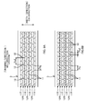
Fig. 9 is an illustrative view of a third example of the arrangement pattern. As can be seen fromFig. 9 , the arrangement pattern is a so-called staggered arrangement. That is to say, theraw sheet 3 has rows ofembossed sections 11R in which the embossedsections sections 11R are provided in such a manner that a plurality of rows are arranged in the CD-direction. Further, positions of the rows ofembossed sections - In this example, the formation pitch Pe in the MD-direction of the embossed
sections sections 11 is determined to satisfy the relationship of Equation 6. Therefore, also for this staggered arrangement, when focusing only on each of the rows ofembossed sections 11R, Equation 6 is satisfied for all the rows of theembossed sections 11R. As a result, inhibition of evenness of stretchability can be effectively suppressed. -
Figs. 10A and 10B are explanatory views of agear drawing apparatus 50 of a second embodiment.Fig. 10A is a front view andFig. 10B is a sectional view taken along B-B inFig. 10A . - The second embodiment differs from the first embodiment described above in which the
raw sheet 3 is drawn in a continuous direction thereof, i.e., the MD-direction, in that theraw sheet 3 is drawn in a width direction thereof, i.e., the CD-direction that corresponds to "a direction parallel to the axes of rotation". Due to this difference, there is also a difference in structure of theteeth - Specifically, as shown in
Figs. 10A and 10B , thegear drawing apparatus 50 includes a pair of upper and lower gear rolls 51, 53, each being capable of rotating about respective axes of rotation C51, C53. Theupper gear roll 51 includesmajor diameter sections 51t andminor diameter sections 51m that are alternately arranged along a direction of the axis of rotation C51 and thelower gear roll 53 similarly includesmajor diameter sections 53t andminor diameter sections 53m that are alternately arranged along a direction of the axis of rotation C53. These gear rolls 51, 53 are arranged one above the other with themajor diameter section minor diameter section major diameter section Fig. 10B .) - Here, the
raw sheet 3 is transported towards the mating region Ab and, while passing the mating region Ab, is drawn in the CD-direction by being deformed into a shape bent at three points as shown inFig. 10A . Then, after being drawn, the stretchability in the CD-direction will develop and thus astretchable sheet 3a having stretchability in the width direction will be produced. - Therefore, the second embodiment differs from the first embodiment in that the drawing direction is CD-direction, instead of MD-direction.
- Based on the above, in the second embodiment, considering that the formation pitch Ped in the CD-direction of the embossed
sections 11 ofFig. 11 corresponds to the formation pitch Pe of the above-mentioned first embodiment and that the arrangement pitch Ptd in the CD-direction of themajor diameter sections 51t (53t), corresponding to the teeth inFig. 10A , corresponds to the arrangement pitch Pt in the above-mentioned first embodiment, the explanation described for the first embodiment can be applied to the second embodiment. Therefore, such explanation will be omitted. - Embodiments of the present invention have been described as above, however the present invention is not limited to these embodiments and the following variants are also possible.
- In the above embodiment, a nonwoven fabric that includes two types of fibers, i.e., the extensible fiber and the stretchable fiber, has been illustrated as the
raw sheet 3 including a plurality of types of fibers. However, the number of types of fibers is by no means limited to two, and may be three or more types. - In the above embodiment, a nonwoven fabric of a type in which the extensible fiber and the stretchable fiber are blended has been illustrated as the
raw sheet 3 including a plurality of types of fibers. However, this can be of a type in which layers of the extensible fiber only and layers of the stretchable fiber only are provided in separate layers which are layered in a thickness direction of the nonwoven fabric. The number of layers is not limited to two, and, for example, may be a nonwoven fabric of a three-layer structure in which a layer of stretchable fiber only is sandwiched between upper and lower layers of extensible fiber only. - In the above embodiment, the
gear drawing apparatus gear drawing apparatus raw sheet 3 and thus a preliminary drawing process may be applied before the gear drawing. Further, a heater or the like that heats the gear rolls 41 and tension rolls may also be disposed and a suction conveyor that is capable of reducing transport tension may be used for transporting thestretchable sheet 3a after the drawing process. - In the description of the embodiments above, although a detailed explanation has not been made on the shape of an embossed
section 11, the shape of the embossedsection 11 is a recessed section having a base surface of a predetermined area. The shape of the base surface is , for example, a circular shape such as a perfect circle and a polygon such as a square and a rhombus. Further, the base surface has an area of, for example, 0.2 to 4 mm2. The embossedsection 11 of such a configuration is formed by being pressed with a plurality of protruded sections on the circumferential surface of at least one of the rolls while the sheet that is to become theraw sheet 3 is passing through a roll gap between the pair of rotating upper and lower rolls. In order to improve the welding property between the fibers during the pressing, these rolls may be heated. - In the description of the embodiments above, specific numerical values of the formation pitches Pe, Pec, Ped of the embossed
section 11 have not been described, but the value of these formation pitches Pe, Pec, Ped are selected from, for example, 1 to 20 mm, so as to satisfy Equation 6. The range of the above-mentioned numerical value is preferably 1 to 10 mm, and more preferably 1 to 3 mm. - Further, the pitch Pr (
Fig. 7 ) between the rows ofembossed sections - In the above-mentioned embodiment, the embossed section has been illustrated as an example of the recessed section formed by the pressing process. However, it is by no means limited thereto as long as it is a recessed section formed by pressing.
-
- 3
- nonwoven fabric (raw sheet), 3a stretchable sheet,
- 3e
- inter-emboss section, 3p section, 3r surrounding section,
- 11
- embossed section (recessed section),
- 11R
- row of embossed sections (row of recessed sections),
- 11Rc
- row of embossed sections (row of recessed sections),
- 12
- embossed section (recessed section),
- 12R
- row of embossed sections (row of recessed sections),
- 40
- gear drawing apparatus (production apparatus),
- 41
- upper gear roll (gear roll), 41a circumferential section,
- 41p
- top section, 41t upper teeth (teeth),
- 43
- lower gear roll (gear roll),
- 43p
- top section, 43t lower tooth (tooth),
- 50
- gear drawing apparatus (production apparatus),
- 51
- upper gear roll (gear roll),
- 51m
- minor diameter section, 51t major diameter section (teeth),
- 53
- lower gear roll (gear roll),
- 53m
- minor diameter section, 53t major diameter section (teeth),
- Ab
- mating region,
- C41
- axis of rotation, C43 axis of rotation,
- C51
- axis of rotation, C53 axis of rotation
Claims (6)
- A method of producing a stretchable sheet, the method comprising:preparing a pair of gear rolls each having a plurality of teeth arranged on a circumference thereof, the gear rolls being rotatable about respective axes of rotation with the teeth meshing each other; anddrawing a raw sheet in a drawing direction using the teeth by passing the raw sheet through a gap between the pair of gear rolls, the raw sheet containing a plurality of types of fibers, the drawing direction being either a direction of rotation of the gear roll or a direction parallel to the axes of rotation,the raw sheet having a plurality of recessed sections formed by pressing, the recessed sections being formed collinearly at least along the drawing direction at a predetermined formation pitch in the drawing direction,with respect to each gear roll of the pair of gear rolls, an arrangement pitch of the teeth in the drawing direction is greater than the formation pitch and smaller than twice as long as the formation pitch.
- The method of producing a stretchable sheet according to claim 1, wherein
the raw sheet includes a plurality of rows of recessed sections, each row including a plurality of the recessed sections arranged collinearly along the drawing direction, the rows being arranged side-by-side in a direction orthogonal to the drawing direction;
in the respective rows of recessed sections, the recessed sections are formed at respective predetermined formation pitches along the drawing direction; and
with respect to each one of the rows of recessed sections in the raw sheet, the arrangement pitch of the teeth in the drawing direction is greater than the formation pitch and smaller than twice as long as the formation pitch. - The method of producing a stretchable sheet according to claim 2, wherein
the plurality of rows of recessed sections includes a row of recessed sections whose formation pitch value is a first predetermined value and a row of recessed sections whose formation pitch value is a second predetermined value;
the first predetermined value and the second predetermined value are different from each other;
an arrangement pitch of the teeth in the drawing direction is greater than the first predetermined value and smaller than twice as long as the first predetermined value; and
an arrangement pitch of the teeth in the drawing direction is greater than the second predetermined value and smaller than twice as long as the second predetermined value. - The method of producing a stretchable sheet according to any one of claims 1 to 3, wherein
fibers constituting the raw sheet are welded with each other at the recessed section; and
an arrangement pattern of the plurality of recessed sections in the raw sheet is a staggered arrangement. - The method of producing a stretchable sheet according to any one of claims 1 to 4, wherein,
the plurality of recessed sections of the raw sheet are also arranged collinearly and form a row of recessed sections in a direction orthogonal to the drawing direction, a plurality of the rows of recessed sections being arranged side-by-side at a second pitch in the drawing direction; and
an arrangement pitch of the teeth in the drawing direction is greater than the second pitch and smaller than twice as long as the second pitch. - An apparatus that produces a stretchable sheet, the apparatus comprising:a pair of gear rolls each having a plurality of teeth arranged on a circumference thereof, the gear rolls being rotatable about respective axes of rotation with the teeth meshing each other,the stretchable sheet being produced by drawing a raw sheet in a drawing direction using the teeth by passing the raw sheet through a gap between the pair of gear rolls, the raw sheet containing a plurality of types of fibers, the drawing direction being either a direction of rotation of the gear roll or a direction parallel to the axes of rotation,the raw sheet having a plurality of recessed sections formed by pressing, the recessed sections being formed collinearly at least along the drawing direction at a predetermined formation pitch in the drawing direction,with respect to each gear roll of the pair of gear rolls, an arrangement pitch of the teeth in the drawing direction is greater than the formation pitch and smaller than twice as long as the formation pitch.
Applications Claiming Priority (2)
| Application Number | Priority Date | Filing Date | Title |
|---|---|---|---|
| JP2010053603A JP5639771B2 (en) | 2010-03-10 | 2010-03-10 | Stretchable sheet manufacturing method and manufacturing apparatus |
| PCT/JP2011/054738 WO2011111579A1 (en) | 2010-03-10 | 2011-03-02 | Elastic sheet manufacturing method and manufacturing apparatus |
Publications (3)
| Publication Number | Publication Date |
|---|---|
| EP2546402A1 true EP2546402A1 (en) | 2013-01-16 |
| EP2546402A4 EP2546402A4 (en) | 2013-11-06 |
| EP2546402B1 EP2546402B1 (en) | 2016-09-07 |
Family
ID=44563383
Family Applications (1)
| Application Number | Title | Priority Date | Filing Date |
|---|---|---|---|
| EP11753238.2A Active EP2546402B1 (en) | 2010-03-10 | 2011-03-02 | Method for producing a stretchable sheet |
Country Status (6)
| Country | Link |
|---|---|
| US (2) | US9296151B2 (en) |
| EP (1) | EP2546402B1 (en) |
| JP (1) | JP5639771B2 (en) |
| CN (1) | CN102791918B (en) |
| TW (1) | TW201144513A (en) |
| WO (1) | WO2011111579A1 (en) |
Families Citing this family (12)
| Publication number | Priority date | Publication date | Assignee | Title |
|---|---|---|---|---|
| JP5639771B2 (en) * | 2010-03-10 | 2014-12-10 | ユニ・チャーム株式会社 | Stretchable sheet manufacturing method and manufacturing apparatus |
| JP5762091B2 (en) * | 2011-03-31 | 2015-08-12 | ユニ・チャーム株式会社 | Method for producing elastic sheet |
| JP5726119B2 (en) * | 2012-03-27 | 2015-05-27 | ユニ・チャーム株式会社 | Method for producing stretchable nonwoven fabric, and stretchable nonwoven fabric |
| JP6012463B2 (en) * | 2012-12-28 | 2016-10-25 | ユニ・チャーム株式会社 | Stretchable sheet manufacturing apparatus and manufacturing method |
| JP6035143B2 (en) * | 2012-12-28 | 2016-11-30 | ユニ・チャーム株式会社 | Stretchable sheet manufacturing apparatus and manufacturing method |
| JP6101485B2 (en) * | 2012-12-28 | 2017-03-22 | ユニ・チャーム株式会社 | Stretchable sheet manufacturing method and stretchable sheet manufacturing apparatus |
| JP5969415B2 (en) * | 2013-03-11 | 2016-08-17 | 花王株式会社 | Method for manufacturing stretchable sheet |
| JP5452756B1 (en) | 2013-07-02 | 2014-03-26 | Hoya株式会社 | Method for producing silicone-containing copolymer molded article having hydrophilic surface and silicone hydrogel contact lens having hydrophilic surface |
| GB2515763A (en) * | 2013-07-02 | 2015-01-07 | Mastercard International Inc | Improvements relating to unpredictable number generation |
| CN103521644B (en) * | 2013-10-25 | 2015-11-25 | 茂名市怡华机械有限公司 | Steel wire embossing machine |
| CN107848237B (en) * | 2015-03-03 | 2021-03-09 | 东罐兴业株式会社 | Paper cup, method and apparatus for manufacturing the same |
| JPWO2022113994A1 (en) * | 2020-11-24 | 2022-06-02 |
Citations (4)
| Publication number | Priority date | Publication date | Assignee | Title |
|---|---|---|---|---|
| WO2002031245A2 (en) * | 2000-10-13 | 2002-04-18 | The Procter & Gamble Company | Abrasion resistant, soft nonwoven |
| US20030028165A1 (en) * | 1999-12-21 | 2003-02-06 | Curro John J | Laminate web comprising an apertured layer and method for manufacture thereof |
| EP1876275A1 (en) * | 2005-04-25 | 2008-01-09 | Kao Corporation | Stretch sheet and process for producing the same |
| EP1956131A1 (en) * | 2005-12-01 | 2008-08-13 | Kao Corporation | Sheet processing device and sheet production method |
Family Cites Families (24)
| Publication number | Priority date | Publication date | Assignee | Title |
|---|---|---|---|---|
| US4223063A (en) * | 1979-03-02 | 1980-09-16 | Sabee Reinhardt N | Pattern drawing of webs, and product produced thereby |
| JPS60143926A (en) | 1983-12-30 | 1985-07-30 | Nippon Petrochem Co Ltd | Method and apparatus for forming rugged sheet |
| US5167897A (en) * | 1991-02-28 | 1992-12-01 | The Procter & Gamble Company | Method for incrementally stretching a zero strain stretch laminate web to impart elasticity thereto |
| US5156793A (en) * | 1991-02-28 | 1992-10-20 | The Procter & Gamble Company | Method for incrementally stretching zero strain stretch laminate web in a non-uniform manner to impart a varying degree of elasticity thereto |
| MY117643A (en) * | 1996-02-29 | 2004-07-31 | Uni Charm Corp | Liquid-permeable topsheet for body exudates absorbent article, apparatus and method for manufacturing same |
| JP4070965B2 (en) | 2001-06-08 | 2008-04-02 | ユニ・チャーム株式会社 | Stretchable composite sheet and method for forming a large number of wrinkles on stretchable composite sheet |
| US7468114B2 (en) * | 2002-11-13 | 2008-12-23 | Kao Corporation | Composite sheet and process and apparatus for producing the same |
| US8030535B2 (en) * | 2002-12-18 | 2011-10-04 | The Procter & Gamble Company | Sanitary napkin for clean body benefit |
| JP4839443B2 (en) * | 2004-06-18 | 2011-12-21 | 国立大学法人東北大学 | Screw vacuum pump |
| US7754050B2 (en) * | 2004-06-21 | 2010-07-13 | The Procter + Gamble Company | Fibrous structures comprising a tuft |
| US20090308524A1 (en) | 2005-04-25 | 2009-12-17 | Kao Corporation | Stretch nonwoven fabric and process of producing the same |
| CN101166859B (en) * | 2005-04-25 | 2010-09-29 | 花王株式会社 | Nonwoven stretch fabric and process for producing the same |
| US20070029073A1 (en) * | 2005-08-04 | 2007-02-08 | Denso Corporation | Production method of offset-shaped fins, fins, and method and apparatus for changing pitch of fins |
| JP4799343B2 (en) * | 2006-09-25 | 2011-10-26 | 花王株式会社 | Sheet manufacturing method and processing apparatus |
| JP5238158B2 (en) | 2006-12-25 | 2013-07-17 | ユニ・チャーム株式会社 | Method for producing elastic sheet |
| US20080271556A1 (en) * | 2007-03-09 | 2008-11-06 | Nidec-Shimpo Corporation | Rotation drive unit and image forming apparatus using same |
| WO2009067507A1 (en) * | 2007-11-19 | 2009-05-28 | The Procter & Gamble Company | Process for activating a web |
| JP5186256B2 (en) | 2008-03-19 | 2013-04-17 | ユニ・チャーム株式会社 | Method for producing elastic sheet |
| JP4468466B2 (en) * | 2008-05-13 | 2010-05-26 | 株式会社椿本チエイン | Chain sprocket |
| PL2411210T3 (en) * | 2009-03-24 | 2017-03-31 | James W. Cree | Embossed textured webs, apparatus and method for making them |
| JP5268854B2 (en) * | 2009-10-09 | 2013-08-21 | 花王株式会社 | Method for producing flexible sheet |
| JP5639771B2 (en) * | 2010-03-10 | 2014-12-10 | ユニ・チャーム株式会社 | Stretchable sheet manufacturing method and manufacturing apparatus |
| JP5506520B2 (en) * | 2010-04-16 | 2014-05-28 | ユニ・チャーム株式会社 | A nonwoven fabric having irregularities, including an extensible fiber and a stretchable fiber, and a method for producing the nonwoven fabric |
| EP2468493A1 (en) * | 2010-12-23 | 2012-06-27 | Boegli-Gravures S.A. | Device for embossing films |
-
2010
- 2010-03-10 JP JP2010053603A patent/JP5639771B2/en active Active
-
2011
- 2011-03-02 EP EP11753238.2A patent/EP2546402B1/en active Active
- 2011-03-02 WO PCT/JP2011/054738 patent/WO2011111579A1/en active Application Filing
- 2011-03-02 US US13/577,030 patent/US9296151B2/en active Active
- 2011-03-02 CN CN201180013048.0A patent/CN102791918B/en active Active
- 2011-03-10 TW TW100108092A patent/TW201144513A/en unknown
-
2015
- 2015-04-09 US US14/683,116 patent/US9616612B2/en not_active Expired - Fee Related
Patent Citations (4)
| Publication number | Priority date | Publication date | Assignee | Title |
|---|---|---|---|---|
| US20030028165A1 (en) * | 1999-12-21 | 2003-02-06 | Curro John J | Laminate web comprising an apertured layer and method for manufacture thereof |
| WO2002031245A2 (en) * | 2000-10-13 | 2002-04-18 | The Procter & Gamble Company | Abrasion resistant, soft nonwoven |
| EP1876275A1 (en) * | 2005-04-25 | 2008-01-09 | Kao Corporation | Stretch sheet and process for producing the same |
| EP1956131A1 (en) * | 2005-12-01 | 2008-08-13 | Kao Corporation | Sheet processing device and sheet production method |
Non-Patent Citations (1)
| Title |
|---|
| See also references of WO2011111579A1 * |
Also Published As
| Publication number | Publication date |
|---|---|
| US9616612B2 (en) | 2017-04-11 |
| EP2546402A4 (en) | 2013-11-06 |
| US20150210000A1 (en) | 2015-07-30 |
| EP2546402B1 (en) | 2016-09-07 |
| CN102791918B (en) | 2015-04-22 |
| JP2011184833A (en) | 2011-09-22 |
| WO2011111579A1 (en) | 2011-09-15 |
| US9296151B2 (en) | 2016-03-29 |
| TW201144513A (en) | 2011-12-16 |
| CN102791918A (en) | 2012-11-21 |
| JP5639771B2 (en) | 2014-12-10 |
| US20130031813A1 (en) | 2013-02-07 |
Similar Documents
| Publication | Publication Date | Title |
|---|---|---|
| EP2546402A1 (en) | Elastic sheet manufacturing method and manufacturing apparatus | |
| KR101290233B1 (en) | Sheet processing device and sheet production method | |
| EP2095939B1 (en) | Composite sheet and absorbent article comprising composite sheet | |
| EP2133453B1 (en) | Nonwoven stretch fabric | |
| AU2010287946B2 (en) | Disposable wearing article | |
| JP5268854B2 (en) | Method for producing flexible sheet | |
| CN102186673B (en) | Method of manufacturing composite sheet, method of producing absorptive article using composite sheet, and device for manufacturing composite sheet | |
| EP2258895A1 (en) | Method for producing stretch sheet | |
| JP2010119743A (en) | Absorbent article and method for producing the same | |
| US9877880B2 (en) | Fastening member having bonded reinforcing layer | |
| EP2090424B1 (en) | Composite sheet and absorbent article comprising the composite sheet | |
| EP2384881A1 (en) | Nonwoven fabric having stretchability, and process for producing the same | |
| JP4799343B2 (en) | Sheet manufacturing method and processing apparatus | |
| US20200383842A1 (en) | Stretch sheet for absorbent article and method for producing the same | |
| WO1997028962A1 (en) | Process for producing a multi-layer elastic surface structure and multi-layer elastic surface structure | |
| GB2580490A (en) | Stretchable sheet for absorptive article and production method for same |
Legal Events
| Date | Code | Title | Description |
|---|---|---|---|
| PUAI | Public reference made under article 153(3) epc to a published international application that has entered the european phase |
Free format text: ORIGINAL CODE: 0009012 |
|
| 17P | Request for examination filed |
Effective date: 20120730 |
|
| AK | Designated contracting states |
Kind code of ref document: A1 Designated state(s): AL AT BE BG CH CY CZ DE DK EE ES FI FR GB GR HR HU IE IS IT LI LT LU LV MC MK MT NL NO PL PT RO RS SE SI SK SM TR |
|
| DAX | Request for extension of the european patent (deleted) | ||
| A4 | Supplementary search report drawn up and despatched |
Effective date: 20131007 |
|
| RIC1 | Information provided on ipc code assigned before grant |
Ipc: B29C 55/18 20060101ALI20130930BHEP Ipc: A61F 13/15 20060101ALI20130930BHEP Ipc: D06C 3/06 20060101AFI20130930BHEP Ipc: A61F 13/56 20060101ALI20130930BHEP |
|
| 17Q | First examination report despatched |
Effective date: 20140530 |
|
| REG | Reference to a national code |
Ref country code: DE Ref legal event code: R079 Ref document number: 602011030154 Country of ref document: DE Free format text: PREVIOUS MAIN CLASS: D06C0003060000 Ipc: D04H0003160000 |
|
| GRAP | Despatch of communication of intention to grant a patent |
Free format text: ORIGINAL CODE: EPIDOSNIGR1 |
|
| RIC1 | Information provided on ipc code assigned before grant |
Ipc: D06C 3/06 20060101ALI20160311BHEP Ipc: D04H 3/16 20060101AFI20160311BHEP Ipc: A61F 13/15 20060101ALI20160311BHEP Ipc: A61F 13/56 20060101ALI20160311BHEP Ipc: B29C 55/18 20060101ALI20160311BHEP Ipc: B29L 31/48 20060101ALI20160311BHEP |
|
| INTG | Intention to grant announced |
Effective date: 20160405 |
|
| GRAS | Grant fee paid |
Free format text: ORIGINAL CODE: EPIDOSNIGR3 |
|
| GRAA | (expected) grant |
Free format text: ORIGINAL CODE: 0009210 |
|
| AK | Designated contracting states |
Kind code of ref document: B1 Designated state(s): AL AT BE BG CH CY CZ DE DK EE ES FI FR GB GR HR HU IE IS IT LI LT LU LV MC MK MT NL NO PL PT RO RS SE SI SK SM TR |
|
| REG | Reference to a national code |
Ref country code: GB Ref legal event code: FG4D |
|
| REG | Reference to a national code |
Ref country code: CH Ref legal event code: EP |
|
| REG | Reference to a national code |
Ref country code: IE Ref legal event code: FG4D |
|
| REG | Reference to a national code |
Ref country code: AT Ref legal event code: REF Ref document number: 826972 Country of ref document: AT Kind code of ref document: T Effective date: 20161015 |
|
| REG | Reference to a national code |
Ref country code: DE Ref legal event code: R096 Ref document number: 602011030154 Country of ref document: DE |
|
| REG | Reference to a national code |
Ref country code: NL Ref legal event code: FP |
|
| REG | Reference to a national code |
Ref country code: SE Ref legal event code: TRGR |
|
| REG | Reference to a national code |
Ref country code: LT Ref legal event code: MG4D |
|
| PG25 | Lapsed in a contracting state [announced via postgrant information from national office to epo] |
Ref country code: RS Free format text: LAPSE BECAUSE OF FAILURE TO SUBMIT A TRANSLATION OF THE DESCRIPTION OR TO PAY THE FEE WITHIN THE PRESCRIBED TIME-LIMIT Effective date: 20160907 Ref country code: LT Free format text: LAPSE BECAUSE OF FAILURE TO SUBMIT A TRANSLATION OF THE DESCRIPTION OR TO PAY THE FEE WITHIN THE PRESCRIBED TIME-LIMIT Effective date: 20160907 Ref country code: HR Free format text: LAPSE BECAUSE OF FAILURE TO SUBMIT A TRANSLATION OF THE DESCRIPTION OR TO PAY THE FEE WITHIN THE PRESCRIBED TIME-LIMIT Effective date: 20160907 Ref country code: NO Free format text: LAPSE BECAUSE OF FAILURE TO SUBMIT A TRANSLATION OF THE DESCRIPTION OR TO PAY THE FEE WITHIN THE PRESCRIBED TIME-LIMIT Effective date: 20161207 Ref country code: FI Free format text: LAPSE BECAUSE OF FAILURE TO SUBMIT A TRANSLATION OF THE DESCRIPTION OR TO PAY THE FEE WITHIN THE PRESCRIBED TIME-LIMIT Effective date: 20160907 |
|
| REG | Reference to a national code |
Ref country code: FR Ref legal event code: PLFP Year of fee payment: 7 |
|
| REG | Reference to a national code |
Ref country code: AT Ref legal event code: MK05 Ref document number: 826972 Country of ref document: AT Kind code of ref document: T Effective date: 20160907 |
|
| PG25 | Lapsed in a contracting state [announced via postgrant information from national office to epo] |
Ref country code: ES Free format text: LAPSE BECAUSE OF FAILURE TO SUBMIT A TRANSLATION OF THE DESCRIPTION OR TO PAY THE FEE WITHIN THE PRESCRIBED TIME-LIMIT Effective date: 20160907 Ref country code: GR Free format text: LAPSE BECAUSE OF FAILURE TO SUBMIT A TRANSLATION OF THE DESCRIPTION OR TO PAY THE FEE WITHIN THE PRESCRIBED TIME-LIMIT Effective date: 20161208 Ref country code: LV Free format text: LAPSE BECAUSE OF FAILURE TO SUBMIT A TRANSLATION OF THE DESCRIPTION OR TO PAY THE FEE WITHIN THE PRESCRIBED TIME-LIMIT Effective date: 20160907 |
|
| PG25 | Lapsed in a contracting state [announced via postgrant information from national office to epo] |
Ref country code: EE Free format text: LAPSE BECAUSE OF FAILURE TO SUBMIT A TRANSLATION OF THE DESCRIPTION OR TO PAY THE FEE WITHIN THE PRESCRIBED TIME-LIMIT Effective date: 20160907 Ref country code: RO Free format text: LAPSE BECAUSE OF FAILURE TO SUBMIT A TRANSLATION OF THE DESCRIPTION OR TO PAY THE FEE WITHIN THE PRESCRIBED TIME-LIMIT Effective date: 20160907 |
|
| PG25 | Lapsed in a contracting state [announced via postgrant information from national office to epo] |
Ref country code: PL Free format text: LAPSE BECAUSE OF FAILURE TO SUBMIT A TRANSLATION OF THE DESCRIPTION OR TO PAY THE FEE WITHIN THE PRESCRIBED TIME-LIMIT Effective date: 20160907 Ref country code: IS Free format text: LAPSE BECAUSE OF FAILURE TO SUBMIT A TRANSLATION OF THE DESCRIPTION OR TO PAY THE FEE WITHIN THE PRESCRIBED TIME-LIMIT Effective date: 20170107 Ref country code: BE Free format text: LAPSE BECAUSE OF FAILURE TO SUBMIT A TRANSLATION OF THE DESCRIPTION OR TO PAY THE FEE WITHIN THE PRESCRIBED TIME-LIMIT Effective date: 20160907 Ref country code: SM Free format text: LAPSE BECAUSE OF FAILURE TO SUBMIT A TRANSLATION OF THE DESCRIPTION OR TO PAY THE FEE WITHIN THE PRESCRIBED TIME-LIMIT Effective date: 20160907 Ref country code: BG Free format text: LAPSE BECAUSE OF FAILURE TO SUBMIT A TRANSLATION OF THE DESCRIPTION OR TO PAY THE FEE WITHIN THE PRESCRIBED TIME-LIMIT Effective date: 20161207 Ref country code: CZ Free format text: LAPSE BECAUSE OF FAILURE TO SUBMIT A TRANSLATION OF THE DESCRIPTION OR TO PAY THE FEE WITHIN THE PRESCRIBED TIME-LIMIT Effective date: 20160907 Ref country code: PT Free format text: LAPSE BECAUSE OF FAILURE TO SUBMIT A TRANSLATION OF THE DESCRIPTION OR TO PAY THE FEE WITHIN THE PRESCRIBED TIME-LIMIT Effective date: 20170109 Ref country code: AT Free format text: LAPSE BECAUSE OF FAILURE TO SUBMIT A TRANSLATION OF THE DESCRIPTION OR TO PAY THE FEE WITHIN THE PRESCRIBED TIME-LIMIT Effective date: 20160907 Ref country code: SK Free format text: LAPSE BECAUSE OF FAILURE TO SUBMIT A TRANSLATION OF THE DESCRIPTION OR TO PAY THE FEE WITHIN THE PRESCRIBED TIME-LIMIT Effective date: 20160907 |
|
| REG | Reference to a national code |
Ref country code: DE Ref legal event code: R097 Ref document number: 602011030154 Country of ref document: DE |
|
| PG25 | Lapsed in a contracting state [announced via postgrant information from national office to epo] |
Ref country code: IT Free format text: LAPSE BECAUSE OF FAILURE TO SUBMIT A TRANSLATION OF THE DESCRIPTION OR TO PAY THE FEE WITHIN THE PRESCRIBED TIME-LIMIT Effective date: 20160907 |
|
| PLBE | No opposition filed within time limit |
Free format text: ORIGINAL CODE: 0009261 |
|
| STAA | Information on the status of an ep patent application or granted ep patent |
Free format text: STATUS: NO OPPOSITION FILED WITHIN TIME LIMIT |
|
| PG25 | Lapsed in a contracting state [announced via postgrant information from national office to epo] |
Ref country code: DK Free format text: LAPSE BECAUSE OF FAILURE TO SUBMIT A TRANSLATION OF THE DESCRIPTION OR TO PAY THE FEE WITHIN THE PRESCRIBED TIME-LIMIT Effective date: 20160907 |
|
| 26N | No opposition filed |
Effective date: 20170608 |
|
| PG25 | Lapsed in a contracting state [announced via postgrant information from national office to epo] |
Ref country code: SI Free format text: LAPSE BECAUSE OF FAILURE TO SUBMIT A TRANSLATION OF THE DESCRIPTION OR TO PAY THE FEE WITHIN THE PRESCRIBED TIME-LIMIT Effective date: 20160907 |
|
| REG | Reference to a national code |
Ref country code: CH Ref legal event code: PL |
|
| PG25 | Lapsed in a contracting state [announced via postgrant information from national office to epo] |
Ref country code: MC Free format text: LAPSE BECAUSE OF FAILURE TO SUBMIT A TRANSLATION OF THE DESCRIPTION OR TO PAY THE FEE WITHIN THE PRESCRIBED TIME-LIMIT Effective date: 20160907 |
|
| REG | Reference to a national code |
Ref country code: IE Ref legal event code: MM4A |
|
| PG25 | Lapsed in a contracting state [announced via postgrant information from national office to epo] |
Ref country code: LU Free format text: LAPSE BECAUSE OF NON-PAYMENT OF DUE FEES Effective date: 20170302 |
|
| REG | Reference to a national code |
Ref country code: FR Ref legal event code: PLFP Year of fee payment: 8 |
|
| PG25 | Lapsed in a contracting state [announced via postgrant information from national office to epo] |
Ref country code: LI Free format text: LAPSE BECAUSE OF NON-PAYMENT OF DUE FEES Effective date: 20170331 Ref country code: CH Free format text: LAPSE BECAUSE OF NON-PAYMENT OF DUE FEES Effective date: 20170331 Ref country code: IE Free format text: LAPSE BECAUSE OF NON-PAYMENT OF DUE FEES Effective date: 20170302 |
|
| PG25 | Lapsed in a contracting state [announced via postgrant information from national office to epo] |
Ref country code: MT Free format text: LAPSE BECAUSE OF NON-PAYMENT OF DUE FEES Effective date: 20170302 |
|
| PG25 | Lapsed in a contracting state [announced via postgrant information from national office to epo] |
Ref country code: AL Free format text: LAPSE BECAUSE OF FAILURE TO SUBMIT A TRANSLATION OF THE DESCRIPTION OR TO PAY THE FEE WITHIN THE PRESCRIBED TIME-LIMIT Effective date: 20160907 |
|
| PG25 | Lapsed in a contracting state [announced via postgrant information from national office to epo] |
Ref country code: HU Free format text: LAPSE BECAUSE OF FAILURE TO SUBMIT A TRANSLATION OF THE DESCRIPTION OR TO PAY THE FEE WITHIN THE PRESCRIBED TIME-LIMIT; INVALID AB INITIO Effective date: 20110302 |
|
| PG25 | Lapsed in a contracting state [announced via postgrant information from national office to epo] |
Ref country code: CY Free format text: LAPSE BECAUSE OF NON-PAYMENT OF DUE FEES Effective date: 20160907 |
|
| PG25 | Lapsed in a contracting state [announced via postgrant information from national office to epo] |
Ref country code: MK Free format text: LAPSE BECAUSE OF FAILURE TO SUBMIT A TRANSLATION OF THE DESCRIPTION OR TO PAY THE FEE WITHIN THE PRESCRIBED TIME-LIMIT Effective date: 20160907 |
|
| PG25 | Lapsed in a contracting state [announced via postgrant information from national office to epo] |
Ref country code: TR Free format text: LAPSE BECAUSE OF FAILURE TO SUBMIT A TRANSLATION OF THE DESCRIPTION OR TO PAY THE FEE WITHIN THE PRESCRIBED TIME-LIMIT Effective date: 20160907 |
|
| PGFP | Annual fee paid to national office [announced via postgrant information from national office to epo] |
Ref country code: DE Payment date: 20200218 Year of fee payment: 10 Ref country code: GB Payment date: 20200219 Year of fee payment: 10 |
|
| PGFP | Annual fee paid to national office [announced via postgrant information from national office to epo] |
Ref country code: FR Payment date: 20200214 Year of fee payment: 10 |
|
| REG | Reference to a national code |
Ref country code: DE Ref legal event code: R119 Ref document number: 602011030154 Country of ref document: DE |
|
| GBPC | Gb: european patent ceased through non-payment of renewal fee |
Effective date: 20210302 |
|
| PG25 | Lapsed in a contracting state [announced via postgrant information from national office to epo] |
Ref country code: FR Free format text: LAPSE BECAUSE OF NON-PAYMENT OF DUE FEES Effective date: 20210331 Ref country code: GB Free format text: LAPSE BECAUSE OF NON-PAYMENT OF DUE FEES Effective date: 20210302 Ref country code: DE Free format text: LAPSE BECAUSE OF NON-PAYMENT OF DUE FEES Effective date: 20211001 |
|
| PGFP | Annual fee paid to national office [announced via postgrant information from national office to epo] |
Ref country code: NL Payment date: 20230215 Year of fee payment: 13 |
|
| PGFP | Annual fee paid to national office [announced via postgrant information from national office to epo] |
Ref country code: SE Payment date: 20230210 Year of fee payment: 13 |
|
| PGFP | Annual fee paid to national office [announced via postgrant information from national office to epo] |
Ref country code: NL Payment date: 20240214 Year of fee payment: 14 |