EP2554895A1 - Tubular lamp and lighting equipment - Google Patents
Tubular lamp and lighting equipment Download PDFInfo
- Publication number
- EP2554895A1 EP2554895A1 EP11762742A EP11762742A EP2554895A1 EP 2554895 A1 EP2554895 A1 EP 2554895A1 EP 11762742 A EP11762742 A EP 11762742A EP 11762742 A EP11762742 A EP 11762742A EP 2554895 A1 EP2554895 A1 EP 2554895A1
- Authority
- EP
- European Patent Office
- Prior art keywords
- lamp
- tube lamp
- apparatus body
- tube
- sockets
- Prior art date
- Legal status (The legal status is an assumption and is not a legal conclusion. Google has not performed a legal analysis and makes no representation as to the accuracy of the status listed.)
- Withdrawn
Links
- 238000003860 storage Methods 0.000 claims description 32
- 238000003780 insertion Methods 0.000 claims description 27
- 230000037431 insertion Effects 0.000 claims description 27
- 239000000758 substrate Substances 0.000 description 45
- 239000000463 material Substances 0.000 description 21
- 238000000034 method Methods 0.000 description 14
- 239000011810 insulating material Substances 0.000 description 8
- 229920003002 synthetic resin Polymers 0.000 description 8
- 239000000057 synthetic resin Substances 0.000 description 8
- 230000006866 deterioration Effects 0.000 description 7
- 238000010586 diagram Methods 0.000 description 6
- 229920005989 resin Polymers 0.000 description 6
- 239000011347 resin Substances 0.000 description 6
- 229910052782 aluminium Inorganic materials 0.000 description 5
- XAGFODPZIPBFFR-UHFFFAOYSA-N aluminium Chemical compound [Al] XAGFODPZIPBFFR-UHFFFAOYSA-N 0.000 description 5
- WABPQHHGFIMREM-UHFFFAOYSA-N lead(0) Chemical compound [Pb] WABPQHHGFIMREM-UHFFFAOYSA-N 0.000 description 5
- 229910052751 metal Inorganic materials 0.000 description 5
- 239000002184 metal Substances 0.000 description 5
- 238000012986 modification Methods 0.000 description 5
- 230000004048 modification Effects 0.000 description 5
- 230000035882 stress Effects 0.000 description 5
- OAICVXFJPJFONN-UHFFFAOYSA-N Phosphorus Chemical compound [P] OAICVXFJPJFONN-UHFFFAOYSA-N 0.000 description 4
- 230000032683 aging Effects 0.000 description 4
- 239000003990 capacitor Substances 0.000 description 4
- 230000015556 catabolic process Effects 0.000 description 4
- 239000000919 ceramic Substances 0.000 description 4
- 238000006731 degradation reaction Methods 0.000 description 4
- 238000009499 grossing Methods 0.000 description 4
- 230000000694 effects Effects 0.000 description 3
- 230000005611 electricity Effects 0.000 description 3
- 239000003822 epoxy resin Substances 0.000 description 3
- 238000000465 moulding Methods 0.000 description 3
- 229920000647 polyepoxide Polymers 0.000 description 3
- RYGMFSIKBFXOCR-UHFFFAOYSA-N Copper Chemical compound [Cu] RYGMFSIKBFXOCR-UHFFFAOYSA-N 0.000 description 2
- 239000011889 copper foil Substances 0.000 description 2
- 238000011161 development Methods 0.000 description 2
- 230000018109 developmental process Effects 0.000 description 2
- 239000011521 glass Substances 0.000 description 2
- 230000007774 longterm Effects 0.000 description 2
- 238000012423 maintenance Methods 0.000 description 2
- 230000000149 penetrating effect Effects 0.000 description 2
- 230000005855 radiation Effects 0.000 description 2
- 238000007789 sealing Methods 0.000 description 2
- 229920002050 silicone resin Polymers 0.000 description 2
- 239000004593 Epoxy Substances 0.000 description 1
- 239000000853 adhesive Substances 0.000 description 1
- 238000004140 cleaning Methods 0.000 description 1
- 238000005520 cutting process Methods 0.000 description 1
- 238000001125 extrusion Methods 0.000 description 1
- 238000003754 machining Methods 0.000 description 1
- 239000007769 metal material Substances 0.000 description 1
- 230000000717 retained effect Effects 0.000 description 1
Images


Classifications
-
- F—MECHANICAL ENGINEERING; LIGHTING; HEATING; WEAPONS; BLASTING
- F21—LIGHTING
- F21V—FUNCTIONAL FEATURES OR DETAILS OF LIGHTING DEVICES OR SYSTEMS THEREOF; STRUCTURAL COMBINATIONS OF LIGHTING DEVICES WITH OTHER ARTICLES, NOT OTHERWISE PROVIDED FOR
- F21V23/00—Arrangement of electric circuit elements in or on lighting devices
- F21V23/003—Arrangement of electric circuit elements in or on lighting devices the elements being electronics drivers or controllers for operating the light source, e.g. for a LED array
- F21V23/004—Arrangement of electric circuit elements in or on lighting devices the elements being electronics drivers or controllers for operating the light source, e.g. for a LED array arranged on a substrate, e.g. a printed circuit board
- F21V23/006—Arrangement of electric circuit elements in or on lighting devices the elements being electronics drivers or controllers for operating the light source, e.g. for a LED array arranged on a substrate, e.g. a printed circuit board the substrate being distinct from the light source holder
-
- F—MECHANICAL ENGINEERING; LIGHTING; HEATING; WEAPONS; BLASTING
- F21—LIGHTING
- F21K—NON-ELECTRIC LIGHT SOURCES USING LUMINESCENCE; LIGHT SOURCES USING ELECTROCHEMILUMINESCENCE; LIGHT SOURCES USING CHARGES OF COMBUSTIBLE MATERIAL; LIGHT SOURCES USING SEMICONDUCTOR DEVICES AS LIGHT-GENERATING ELEMENTS; LIGHT SOURCES NOT OTHERWISE PROVIDED FOR
- F21K9/00—Light sources using semiconductor devices as light-generating elements, e.g. using light-emitting diodes [LED] or lasers
- F21K9/20—Light sources comprising attachment means
- F21K9/27—Retrofit light sources for lighting devices with two fittings for each light source, e.g. for substitution of fluorescent tubes
-
- F—MECHANICAL ENGINEERING; LIGHTING; HEATING; WEAPONS; BLASTING
- F21—LIGHTING
- F21S—NON-PORTABLE LIGHTING DEVICES; SYSTEMS THEREOF; VEHICLE LIGHTING DEVICES SPECIALLY ADAPTED FOR VEHICLE EXTERIORS
- F21S8/00—Lighting devices intended for fixed installation
- F21S8/03—Lighting devices intended for fixed installation of surface-mounted type
- F21S8/031—Lighting devices intended for fixed installation of surface-mounted type the device consisting essentially only of a light source holder with an exposed light source, e.g. a fluorescent tube
-
- F—MECHANICAL ENGINEERING; LIGHTING; HEATING; WEAPONS; BLASTING
- F21—LIGHTING
- F21V—FUNCTIONAL FEATURES OR DETAILS OF LIGHTING DEVICES OR SYSTEMS THEREOF; STRUCTURAL COMBINATIONS OF LIGHTING DEVICES WITH OTHER ARTICLES, NOT OTHERWISE PROVIDED FOR
- F21V23/00—Arrangement of electric circuit elements in or on lighting devices
- F21V23/06—Arrangement of electric circuit elements in or on lighting devices the elements being coupling devices, e.g. connectors
-
- F—MECHANICAL ENGINEERING; LIGHTING; HEATING; WEAPONS; BLASTING
- F21—LIGHTING
- F21V—FUNCTIONAL FEATURES OR DETAILS OF LIGHTING DEVICES OR SYSTEMS THEREOF; STRUCTURAL COMBINATIONS OF LIGHTING DEVICES WITH OTHER ARTICLES, NOT OTHERWISE PROVIDED FOR
- F21V27/00—Cable-stowing arrangements structurally associated with lighting devices, e.g. reels
- F21V27/02—Cable inlets
-
- F—MECHANICAL ENGINEERING; LIGHTING; HEATING; WEAPONS; BLASTING
- F21—LIGHTING
- F21V—FUNCTIONAL FEATURES OR DETAILS OF LIGHTING DEVICES OR SYSTEMS THEREOF; STRUCTURAL COMBINATIONS OF LIGHTING DEVICES WITH OTHER ARTICLES, NOT OTHERWISE PROVIDED FOR
- F21V29/00—Protecting lighting devices from thermal damage; Cooling or heating arrangements specially adapted for lighting devices or systems
- F21V29/50—Cooling arrangements
- F21V29/70—Cooling arrangements characterised by passive heat-dissipating elements, e.g. heat-sinks
- F21V29/74—Cooling arrangements characterised by passive heat-dissipating elements, e.g. heat-sinks with fins or blades
- F21V29/75—Cooling arrangements characterised by passive heat-dissipating elements, e.g. heat-sinks with fins or blades with fins or blades having different shapes, thicknesses or spacing
-
- F—MECHANICAL ENGINEERING; LIGHTING; HEATING; WEAPONS; BLASTING
- F21—LIGHTING
- F21V—FUNCTIONAL FEATURES OR DETAILS OF LIGHTING DEVICES OR SYSTEMS THEREOF; STRUCTURAL COMBINATIONS OF LIGHTING DEVICES WITH OTHER ARTICLES, NOT OTHERWISE PROVIDED FOR
- F21V29/00—Protecting lighting devices from thermal damage; Cooling or heating arrangements specially adapted for lighting devices or systems
- F21V29/50—Cooling arrangements
- F21V29/70—Cooling arrangements characterised by passive heat-dissipating elements, e.g. heat-sinks
- F21V29/74—Cooling arrangements characterised by passive heat-dissipating elements, e.g. heat-sinks with fins or blades
- F21V29/76—Cooling arrangements characterised by passive heat-dissipating elements, e.g. heat-sinks with fins or blades with essentially identical parallel planar fins or blades, e.g. with comb-like cross-section
- F21V29/763—Cooling arrangements characterised by passive heat-dissipating elements, e.g. heat-sinks with fins or blades with essentially identical parallel planar fins or blades, e.g. with comb-like cross-section the planes containing the fins or blades having the direction of the light emitting axis
-
- F—MECHANICAL ENGINEERING; LIGHTING; HEATING; WEAPONS; BLASTING
- F21—LIGHTING
- F21V—FUNCTIONAL FEATURES OR DETAILS OF LIGHTING DEVICES OR SYSTEMS THEREOF; STRUCTURAL COMBINATIONS OF LIGHTING DEVICES WITH OTHER ARTICLES, NOT OTHERWISE PROVIDED FOR
- F21V29/00—Protecting lighting devices from thermal damage; Cooling or heating arrangements specially adapted for lighting devices or systems
- F21V29/85—Protecting lighting devices from thermal damage; Cooling or heating arrangements specially adapted for lighting devices or systems characterised by the material
- F21V29/89—Metals
-
- F—MECHANICAL ENGINEERING; LIGHTING; HEATING; WEAPONS; BLASTING
- F21—LIGHTING
- F21V—FUNCTIONAL FEATURES OR DETAILS OF LIGHTING DEVICES OR SYSTEMS THEREOF; STRUCTURAL COMBINATIONS OF LIGHTING DEVICES WITH OTHER ARTICLES, NOT OTHERWISE PROVIDED FOR
- F21V3/00—Globes; Bowls; Cover glasses
- F21V3/02—Globes; Bowls; Cover glasses characterised by the shape
-
- F—MECHANICAL ENGINEERING; LIGHTING; HEATING; WEAPONS; BLASTING
- F21—LIGHTING
- F21Y—INDEXING SCHEME ASSOCIATED WITH SUBCLASSES F21K, F21L, F21S and F21V, RELATING TO THE FORM OR THE KIND OF THE LIGHT SOURCES OR OF THE COLOUR OF THE LIGHT EMITTED
- F21Y2103/00—Elongate light sources, e.g. fluorescent tubes
- F21Y2103/10—Elongate light sources, e.g. fluorescent tubes comprising a linear array of point-like light-generating elements
-
- F—MECHANICAL ENGINEERING; LIGHTING; HEATING; WEAPONS; BLASTING
- F21—LIGHTING
- F21Y—INDEXING SCHEME ASSOCIATED WITH SUBCLASSES F21K, F21L, F21S and F21V, RELATING TO THE FORM OR THE KIND OF THE LIGHT SOURCES OR OF THE COLOUR OF THE LIGHT EMITTED
- F21Y2115/00—Light-generating elements of semiconductor light sources
- F21Y2115/10—Light-emitting diodes [LED]
Definitions
- Embodiments of the present invention relates to a tube lamp which can be used instead of a tube fluorescent lamp and uses, for example, LEDs as light sources, and to a luminaire using the tube lamp.
- LEDs light-emitting diodes
- luminaire using the LEDs has a long service life and consumes less power in comparison with existing luminaire such as fluorescent lamps. Therefore, running cost is low and the number of times of replacement of equipment or maintenance on the basis of service life can be reduced.
- a straight tube lamp using LEDs arranged in a row as light sources which can be used by being replaced instead of existing straight tube fluorescent lamp is in widespread use.
- the tube lamp using the current LEDs has a structure to be mounted and feed power by inserting bases provided at both ends thereof into sockets on an apparatus body side, it is necessary to provide a complicated circuit configuration on a lamp side in conformity to a lighting system on the apparatus body side. Therefore, the cost of the lamp is inevitably increased.
- a force of the sockets of the existing apparatus body to hold the bases may be weakened due to aging degradation, and there is a risk of dropping of the tube lamp, and electrical connection may result in a higher rate of unstable electric connection.
- a tube lamp of an embodiment comprising: an elongated cylindrical lamp body having translucency; a plurality of light-emitting elements arranged in the lamp body; two mounting portions configured to mount both ends of the lamp body in the longitudinal direction respectively to sockets of an apparatus body; and a feeding unit provided on the lamp body separately from the two mounting portions for feeding power to the light-emitting element.
- a tube lamp which provides a high compatibility with existing straight tube fluorescent lamps can be manufactured by itself at low cost, and has no fear of dropping from the apparatus body, and a luminaire using such a tube lamp can be provided.
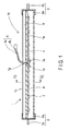
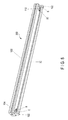
- FIG. 1 illustrates a cross-sectional view of a tube lamp 10 according to a first embodiment taken in a longitudinal direction along a tube axis thereof.
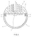
- FIG. 2 shows a cross-sectional view of the tube lamp 10 taken along a plane orthogonal to the tube axis thereof.
- a straight tube lamp having a substantially cylindrical shape extending straight as illustrated in FIG. 1 will be described as an example of tube lamps.
- the tube lamp 10 has a structure which can be used instead of an existing straight tube fluorescent lamp (not illustrated).
- the tube lamp 10 in this embodiment can be used by being mounted on an apparatus body 100 (described in detail later) of a luminaire configured to be used by mounting the straight tube fluorescent lamp in the related art.
- the tube lamp 10 in this embodiment includes an elongated straight tube lamp body 1 of a substantially cylindrical shape, a plurality (eight in this embodiment) of LEDs 2 (light-emitting elements) arranged in a line in the longitudinal direction in the ,lamp body 1, two substrates 4 on which the plurality of LEDs 2 are mounted, two bases 6 (mounting portion) mounted respectively on both ends of the lamp body 1 in the longitudinal direction for mounting the lamp body 1 on the apparatus body 100, and feeding unit 8 configured to feed power to eight of the LEDs 2.
- LEDs 2 light-emitting elements
- the tube lamp 10 in this embodiment is characterized by a structure in which a plurality of the LEDs 2 are disposed side by side along the direction of an tube axis, and eight of the LEDs 2 are mounted on the two substrates 4, that is, four on each of the substrates 4, respectively.
- the feeding unit 8 is provided on the back side of the lamp body 1 in the direction in which the tube lamp 10 faces the apparatus body 100.
- the lamp body 1 includes a translucent cover 1a, and a thermal radiating unit 1b formed of an aluminum extruded material.
- the cover 1a has a shape obtained by cutting a substantially cylindrical shape along a center line thereof, and includes engaging edge portions 1c extending in the longitudinal direction for engaging the thermal radiating units 1b at both side edge portions facing the thermal radiating unit 1b.
- the material of the cover 1a is preferably a material which can diffuse light.
- the thermal radiating unit 1b includes engaging step portions 1d extending in the longitudinal direction for allowing engaging edge portions 1c of the cover 1a to be fitted thereto.
- the cover 1a is slid in the longitudinal direction to engage the engaging edge portions 1c and the engaging step portions 1d.
- the thermal radiating unit 1b integrally includes a mounting base 1e for mounting the substrates 4 on which the LEDs 2 are mounted, and a plurality of thermal radiating fins 1f extending upright from a back side (upper side in FIG. 2 ) of the mounting base 1e.
- the material of the thermal radiating unit 1b is preferably a metallic material having high thermal efficiency.
- connectors 3a for connecting a feeding wire 8a respectively.
- a lead hole 1g penetrating therethrough for leading out the feeding wire 8a connected to the connectors 3a from the back side of the lamp body 1 to the outside.
- the feeding wire 8a led via the lead hole 1g is drawn out to the back side of the lamp body 1 from between the thermal radiating fins 1f.
- the two bases 6 are provided so as to support both ends of the lamp body 1 respectively with respect to the apparatus body 100 of the luminaire to which the existing straight tube fluorescent lamp (not illustrated) can be mounted as illustrated in FIG. 5 and FIG. 6 .
- the lamp body 1 is mounted on the apparatus body 100 by mounting the two bases 6 located at the both ends thereof to two sockets 102 of the apparatus body 100, respectively.
- the two bases 6 have a strength enough to support the own weight of the lamp body 1.
- Each of the two bases 6 integrally includes a bottomed cylindrical shaped cap 6a (fixture) to be mounted at an end portion of the lamp body 1 and two pins 6b (connectors) projecting from the bottom of the cap 6a.
- the two pins 6b are connected to terminals of the sockets 102 of the apparatus body 100.
- the shape of the terminals of the bases 6 is determined according to the shape of the terminals of the sockets 102 on the apparatus body 100 side.
- the cap 6a and the pins 6b are formed respectively of a metal.
- the two bases 6 have thermal conductivity, respectively. Then, the two bases 6 are mounted respectively to the both ends of the lamp body 1 by bonding the caps 6a to the end portions of the lamp body 1 by caulking or with an adhesive agent such as a resin.
- the bases 6 in this embodiment is not provided as feed terminals for feeding electricity from the apparatus body 100 side to the lamp body 1, and is simply be provided for mounting the lamp body 1 to the apparatus body 100.
- the bases 6 are connected to the sockets 102 of the apparatus body 100 in an insulated state.
- the two pins 6b of the bases 6 are connected to the caps 6a in the insulated state.
- the two pins 6b of the respective bases 6 are in the insulated sate with respect to each other.
- the bases 6 are electrically opened, and even when electricity is supplied to the two pins 6b from the side of the apparatus body 100 to the two pins 6b via the sockets 102, the LEDs 2 in the lamp body 1 are not energized via the bases 6.
- the feeding unit 8 for feeding electricity to the plurality of LEDs 2 separately from the two bases 6.
- the feeding unit 8 is provided on the lamp body 1 for connecting the lamp body 1 to an external power supply for supplying power to the LEDs 2. More specifically, the feeding unit 8 includes the feeding wire 8a connected to the connectors 3a mounted on the substrates 4 and a connector 8b provided at a distal end of the feeding wire 8a.
- the feeding wire 8a is led out from the back side of the lamp body 1 via the lead hole 1g of the thermal radiating unit 1b, and in a midcourse thereof, is fixed to the lamp body 1 by a tensile force stopper or the like, not illustrated here.
- a stress applied to the feeding wire 8a is prevented from being applied to connecting portions with respect to the connectors 3a on the substrates 4. For example, even when the feeding wire 8a is pulled, application of an unintended force to the connectors 3a is prevented.
- fixation may be achieved by storing the feeding wire 8a in the lamp body 1, and fixing the connector 8b to the lamp body 1 by direct mount.
- the connector 8b of the feeding unit 8 is secured to the back side of the mounting base 1e between the thermal radiating fins 1f.
- the feeding unit 8 (the feeding wire 8a and the connector 8b) is provided on the back side in the direction in which the lamp body 1 faces the apparatus body 100. Therefore, in a state in which the lamp body 1 is mounted on the apparatus body 100, the feeding wire 8a and the connector 8b are hidden on the back side of the lamp body 1, and the feeding wire 8a and the connector 8b can hardly be seen from the front side of the luminaire, that is, from the side where illuminating light is extracted.
- a connecting portion 104 on the apparatus body 100 side for connecting the feeding unit 8 of the lamp body 1 to the apparatus body 100 includes a connector 104b to be connected to the connector 8b of the feeding unit 8 and a connecting wire 104a having the connector 104b at one end thereof.
- the feeding wire 8a and the connecting wire 104a connected via the connectors 8b, 104b function as a feeding wire 9 for feeding power to the plurality of LEDs 2.
- the translucent cover 1a and the thermal radiating unit 1b define a space for disposing the LEDs 2 in the interior of the lamp body 1.
- the outline of the lamp body 1 has a substantially cylindrical shape, and the cover 1a provides at least part of the lamp body 1 with translucency.
- the LEDs 2 disposed in the lamp body 1 face the inner surface of the cover 1a. Therefore, when the LEDs 2 are lit, light radiated from the LEDs 1 is radiated from the front of the tube lamp 10 via the cover 1a.
- the LEDs 2 are lit by receiving a supply of power from the outside via the feeding unit 8.
- the bases 6 at the both ends of the lamp body 1 are provided only for causing the socket 102 of the apparatus body 100 to support the lamp body 1. Therefore, according to the present embodiment, irrespective of the lighting method of the existing luminaire, the tube lamp 10 which can supply desired power to the lamp body 1 via the feeding unit 8, and enhance general versatility is provided.
- the sockets 102 of the apparatus body 100 of the existing luminaire is subjected to aging degradation, since the supply of power through the feeding unit 8 provided separately from the bases 6 is possible, reliability of electrical connection can be secured.
- the feeding unit 8 since the feeding unit 8 is led out from the vicinity of the center of the lamp body 1 in the direction of the tube axis as illustrated in FIG. 1 , when mounting the bases 6 of the tube lamp 10 to the sockets 102 of the apparatus body 100, the feeding wire 8a or the connector 8b of the feeding unit 8 can hardly interfere with the bases 6 and the sockets 102. Therefore, even though the feeding wire 8a is led out from the lamp body 1, the mounting workability of the lamp body 1 may be facilitated.
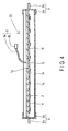
- FIG. 4 illustrates a cross-sectional view of a tube lamp 20 according to a second embodiment.
- the tube lamp 20 has the same structure as the above-described first embodiment except that a lighting circuit 12 is mounted in the lamp body 1. Therefore, the components which function in the same manner as the first embodiment described above are designated by the same reference signs, and the detailed description is omitted.
- the lighting circuit 12 is mounted on the back side of the substrates 4, and the feeding wire 8a of the feeding unit 8 is drawn out from the lighting circuit 12. Then, the connector 8b of the feeding unit 8 is connected to a commercial power supply, not illustrated here. In other word, the commercial power is supplied to the lighting circuit 12.
- the lighting circuit 12 generates a lighting power for lighting the LEDs 2 from the supplied commercial power, and supplies the same to the LEDs 2.
- the lighting circuit 12 is disposed in the lead hole 1g of the mounting base 1e, an the feeding wire 8a of the feeding unit 8 is led out from near the center of the lamp body 1 in the direction of the tube axis to the outside.
- the shape and the size of the lead hole 1g is set so as to be in conformity to the lighting circuit 12.
- the power supplied to the feeding unit 8 is not specifically limited. However, when supplying the commercial power at a rating of 200V or higher, a configuration in which the tube lamp 20 side and the commercial power supply side can be brought into an earth connection by connecting the connector 8b of the feeding unit 8 with the commercial power supply is preferable.
- the lighting circuit 12 to be disposed in the tube lamp 20 may be part of the lighting circuit for lighting control of the LEDs 2.
- the tube lamp 20 is supported by the sockets 102 configured to hold the fluorescent lamp of the related art, and therefore, the lighter weight is preferable.
- the common circuit portion on the apparatus body 100 side and disposing only part of the lighting circuit on the lamp body 1, the light weight of the tube lamp 20 is achieved and the burden imposed at the time of replacement is also reduced.
- it may be achieved by disposing a circuit configured to convert the commercial power supply to DC power supply on the apparatus body 100 side, and disposing the circuit configured to supply power from the DC power supply to the LED 2 in the lamp body 1.
- the substrate is composed of a single substrate 4, and the lighting circuit 12 is mounted on the back side of the substrate 4 and the lighting circuit 12 is disposed in the lead hole 1g.
- this embodiment is not limited thereto, and a storage portion for disposing the lighting circuit 12 on the mounting base 1e may be provided, or the lighting circuit 12 may be disposed on the mounting surface side of the substrate 4 where the LEDs 2 are disposed, or may be configured as a member separate from the substrate 4.
- FIG. 5 illustrates a schematic drawing of a luminaire 200 with either one of the tube lamps 10 and 20 according to the first and second embodiment described above mounted on the apparatus body 100.
- FIG. 6 illustrates a schematic drawing illustrating a state in which one (right side in the drawing) of the bases 6 of the tube lamp 10 or 20 come apart from the sockets 102 from the state illustrated in FIG. 5 .
- the apparatus body 100 of the luminaire 200 includes the two sockets 102 provided respectively at both ends in the longitudinal direction thereof.
- the respective sockets 102 are suspended from a lower surface side of the apparatus body 100 at both ends in the longitudinal direction.
- the tube lamp 10 or 20 is disposed between these two sockets 102 and is mounted on the apparatus body 100 by connecting the bases 6 on the both ends to the terminal of the sockets 102.
- the apparatus body 100 includes a lighting apparatus 106 which is capable of supplying power to terminals, not illustrated, of the sockets 102.
- the lighting apparatus 106 is for a lighting control of the existing straight fluorescent lamp.
- the lighting apparatus 106 since the lighting apparatus 106 is an unnecessary configuration when using the tube lamp 10 or 20 in the respective embodiment described above, the lighting apparatus 106 may be removed at the same time as the replacement of the tube lamp 10 or 20. However, the lighting apparatus 106 may be retained in the apparatus body 100 as-is.
- the apparatus body 100 includes a lighting apparatus 108 for a lighting control of the plurality of LEDs 2 of the tube lamp 10 or 20.
- a proximal end portion of the connecting wire 104a of the connecting portion 104 described above is connected to the lighting apparatus 108.
- the connector 104b of the connecting portion 104 is connected to the connector 8b of the feeding unit 8 on the lamp body 1 side. Then, the power from the lighting apparatus 108 is supplied to the feeding unit 8 via the connecting portion 104.
- the connecting wire 104a led from the apparatus body 100 is fixed to the apparatus body 100 by a tensile force stopper 105 at a midpoint thereof. Accordingly, even when the connecting wire 104a is pulled unintentionally, there is no fear of application of an unintentional stress to the connecting portion of the proximal end portion of the connector 104b with respect to the lighting apparatus 108.
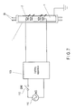
- FIG. 7 illustrates a circuit diagram of the luminaire 200 described above.
- the lighting apparatus 108 is connected to a plurality of the LEDs 2 via the feeding wire 9.
- the feeding wire 9 described here includes the feeding wire 8a and the connector 8b of the feeding unit 8 on the lamp body 1 side and the connecting wire 104a and the connector 104b of the connecting portion 104 on the side the apparatus body 100 as described above.
- a commercial AC power supply 110 is connected to the lighting apparatus 108, and the plurality of LEDs 2 can be lit and extinguished by turning a switch 112 ON and OFF. As illustrated in FIG. 7 , no power supply is connected to the bases 6 at the both ends of the lamp body 1 in the longitudinal direction, and electrically opened state is assumed.
- the straight tube fluorescent lamp is disconnected from the apparatus body 100 of the luminaire 200 in a state of being installed on a ceiling surface or the like on the building.
- the lighting apparatus 108 is mounted on the apparatus body 100.
- the commercial power supply is connected to the lighting apparatus 108.
- the unnecessary lighting apparatus 106 for the fluorescent lamp may be removed from the apparatus body 100.
- part of the apparatus body 100 is formed with an insertion hole for leading out the connecting wire 104a.
- the connecting wire 104a is lead out to the outside from the apparatus body 100 through the insertion hole.
- the midsection of the connecting wire 104a is fixed to the apparatus body 100 by the tensile force stopper 105.
- the bases 6 at the both ends of the tube lamp 10 or 20 are mounted to the respective sockets 102.
- the connector 8b at a distal end of the feeding wire 8a led out from the tube lamp 10 or 20 and the connector 104b at the distal end of the connecting wire 104a are connected.
- a lighting power is supplied to the plurality of LEDs 2 via the connecting portion 104 and the feeding unit 8, and the plurality of LEDs 2 emit light.
- the feeding unit 8 and the connecting portion 104 may be configured to be connected automatically by the operation of connecting the bases 6 to the sockets 102.
- a method of fixing parts of the feeding unit 8 and the connecting portion 104 to be connected via the connector respectively to the lamp body 1 and the apparatus body 100 to achieve a positional relationship so that the both are connected when the bases 6 is mounted on the sockets 102 is conceivable.
- the feeding unit 8 and the connecting portion 104 can be connected via the connector by the operation to mount the bases 6 to the sockets 102.
- These mounting structures only have to be the same structure as the connecter connection between the feeding unit 8 and the connecting portion 104. However, power does not have to be supplied, and only the other side of the tube lamp 10 or 20 has to be supported by the apparatus body 100.
- the tube lamp 10 or 20 can be mounted on the apparatus body 100.
- FIG. 6 is a drawing illustrating a state in which a support of one (right side in the drawing) of the bases 6 of the tube lamp 10 or 20 comes apart. As illustrated in FIG. 6 , even though at least one of the bases 6 comes apart, the tube lamp 10 or 20 can be maintained by the connection between the feeding unit 8 and the connecting portion 104 and the engagement between the other base 6 and the sockets 102.
- the feeding wire 9 support a portion of the lamp body 1 near the center and the other base 6 of the lamp body 1 is supported by the sockets 102. Therefore, even though one of the bases 6 comes apart, dropping of the tube lamp 10 or 20 does not occur, and also the fact that the sockets 102 are deteriorated is notified to users.
- the feeding unit 8 Since the feeding unit 8 is led out from the portion of the lamp body 1 in the vicinity of the center along the direction of an tube axis, a load applied to the engaging portion between the feeding unit 8 and the connecting portion 104 is reduced as illustrated in FIG. 6 , and hence the tube lamp 10 or 20 can be held with a smaller engaging force.
- the probability of dropping of the two bases 6 at the both ends of the lamp body 1 from the sockets 102 simultaneously is low. Normally, either one of those drops first.
- the tube lamp 10 or 20 can be maintained by the engagement between the feeding unit 8 and the connecting portion 104 and the engagement between the other base 6 and the socket 102. Therefore, even when the tube lamp 10 or 20 is used instead of the straight fluorescent lamp for the apparatus body 100 of the luminaire 200 which is subjected to aging degradation after a long time of usage, the safety can be ensured. In particular, by configuring that the own weight of the tube lamp 10 or 20 can be supported by the connection between the feeding unit 8 and the connecting portion 104, the safety is further secured.
- FIG. 8 to FIG. 16 a third embodiment will be described.
- the components which function as those in the first and second embodiments are designated by the same reference signs, and detailed description may be omitted.
- FIG. 8 illustrates an appearance perspective view of a luminaire 300 of this embodiment
- FIG. 9 illustrates a side view of the luminaire 300 viewed from the side
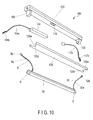
- FIG. 10 also illustrates an exploded perspective views of the luminaire 300.
- the luminaire 300 of this embodiment also includes the apparatus body 100 to be mounted on the ceiling surface or the like of the building and a tube lamp 30 to be mounted on the apparatus body 100.
- the apparatus body 100 in which the existing straight fluorescent lamp has been mounted, has a structure which allows the straight fluorescent lamp to be replaced by the tube lamp 30.
- the apparatus body 100 is configured in such a manner that the tube lamp 30 is mounted between the two sockets 102 by mounting the two bases 6 at the both ends of the tube lamp 30 to the two sockets 102 mounted at the both ends of the longitudinal direction.
- the tube lamp 30 of this embodiment includes the same dimensions and outlines as the existing straight tube fluorescent lamp. More specifically, the tube lamp 30 has the same dimensions and the outline as the straight fluorescent lamp of 40W.
- the tube lamp 30 also has the substrates 4 on which the plurality of LEDs 2 are mounted in the lamp body 1 being elongated and having a substantially cylindrical shape in appearance, the two bases 6 at the both ends of the lamp body 1, and the feeding unit 8 and a grounding portion 32 on the lamp body 1.
- the lamp body 1 includes a semi-cylindrical translucent cover 1a and a semi-cylindrical thermal radiating unit 1b.
- the thermal radiating unit 1b is formed of an aluminum material by an extruded molding, and includes a plurality of the thermal radiating fins 1f so as to extend upright in the longitudinal direction from the back side of the mounting base 1e where the substrates 4 having the LEDs 2 mounted thereon is mounted.
- the cover 1a is mounted on the mounting base 1e of the thermal radiating unit 1b on the opening side thereof so as to be fitted thereto, and defines a substantially cylindrical outline in cooperation with the thermal radiating unit 1b.
- Adhered to the front side of the mounting base 1e of the thermal radiating unit 1b are the elongated substrates 4 having a plurality of LEDs 2 mounted thereon.
- the substrates 4 are formed into a substantially rectangular shape and, more specifically, four of the substrates 4 are mounted on the mounting base 1e of the thermal radiating unit 1b in line in the longitudinal direction so that the back sides thereof come into tight contact therewith.
- the substrate 4 is formed of a flat plate formed of glass epoxy resin which is an insulating material, and a wiring pattern formed of copper foil is applied on the front surface side. Also, a resist layer is applied as needed.
- the insulating material is used as the material of the substrate 4, ceramics materials or synthetic resin materials may be applied.
- the metal it is preferable to apply materials having desirable thermal conductivity and superior in thermal radiating properties like aluminum or the like.
- the light-emitting elements of the embodiment are the LEDs and a surface-mounted LED package.
- the light-emitting element includes an LED chip disposed on a main body formed of ceramics and a translucent resin for molding such as epoxy-based resin or silicone resin for sealing the LED chip.
- the LED chip is a blue LED chip emitting blue light.
- the translucent resin is mixed with phosphor, and yellow phosphor which emits yellowish light which is in a compensating relationship with the blue light in order to allow emission of white light.
- the LEDs 2 may be configured by mounting LED chips directly on the substrates 4, or by mounting bombshell-shaped LEDs thereon.
- the method or the form of mounting the LEDs is not specifically limited. In the embodiment, four each of the LEDs 2 are mounted linearly along the longitudinal direction on one of the substrates 4.
- the bases 6 are, for example, a G13-type base, and are configured to be mountable on the sockets 102 of the luminaire 300 where the existing straight fluorescent lamp is mounted, and are securely provided at the both ends of the lamp body 1.
- the bases 6 each include a pair of the pins 6b so as to project integrally from the bottom of the caps 6a.
- the bases 6 are formed of a metal, and the pair of pins 6b are configured to be electrically insulated.
- the pins 6b are not electrically connected to the LEDs 2.
- the bases 6 are electrically opened, and even when power is supplied to the pins 6b, the electric current does not flow to the pins 6b. Therefore, as described later, when the bases 6 are connected to the sockets 102 of the apparatus body 100 of the luminaire 300, electrical conduction does not occur, and the function to support the tube lamp 30 by the apparatus body 100 is achieved.
- the pins 6b may be formed of an insulating material or may be coated with an insulating material. In this case, the double safety is secured coupled with the fact that the pair of pins 6b are configured to be in the electrically insulated state.
- the feeding unit 8 is connected to the power-supply side, that is, the apparatus body 100 side, and has a function to supply the electric power to the LEDs 2 through the substrates 4.
- the feeding unit 8 of this embodiment includes the connector 8b and the feeding wire 8a having the connector 8b at one end thereof, and is disposed so as to lean on one side of the lamp body 1 in the longitudinal direction (left end in FIG. 14 , for example).
- the connector 8b is provided at the distal end of the feeding wire 8a, is formed of a synthetic resin material, and is configured to be connected electrically and mechanically to the connector 104b provided at the distal end of the connecting wire 104a described later led out from the apparatus body 100 side.
- the connectors 3a electrically connected to the wiring pattern on the substrates 4, and electrically connected to the LEDs 2.
- the connectors 3a pass through a through hole formed on the mounting base 1e of the thermal radiating unit 1b and project upward from the upper side of the mounting base 1e. A proximal end of the feeding wire 8a of the feeding unit 8 is firmly connected to the connectors 3a.
- Part of the feeding wire 8a may be fixed to the lamp body 1 by a tensile force stopper, not illustrated, here. Accordingly, direct application of the stress to be applied to the feeding wire 8a on the connecting portion with respect to the connectors 3a is avoided.
- the connector 8b of the feeding unit 8 may be provided by fixing directly to the back side of the substrates 4 without providing the feeding wire 8a. In this case, the feeding unit 8 is configured of the connector 8b.
- the grounding portion 32 is provided so that the metallic thermal radiating unit 1b of the lamp body 1 is grounded to an earth terminal of the terminal bed 110 provided on the apparatus body 100.
- the grounding portion 32 is provided so as to lean on the other side (right end in FIG. 14 ) of the lamp body 1.
- the grounding portion 32 on the lamp body 1 side includes a grounding wire 32a and a connector 32b attached to the distal end of the grounding wire 32a.
- the proximal end portion of the grounding wire 32a is fixed by a fixing device such as a screw to the mounting base 1e of the thermal radiating unit 1b.
- the grounding wire 32a may be fixed to the lamp body 1 by a tensile force stopper, not illustrated.
- the connector 32b is provided at the distal end of the grinding wire 32a, is formed of a synthetic resin material, and is configured to be connected to the connector 112b provided at the distal end of the grounding wire 112a led out from the apparatus body 100 side, described later.
- the grounding wire 32a and the connector 32b on the lamp body 1 side, and the grounding wire 112a and the connector 112b on the apparatus body 100 side function as grounding wires as a whole, and electrically and mechanically connect the lamp body 1 to the apparatus body 100.
- the apparatus body 100 is formed into a box shape having an opening portion opened on a lower side, and includes the sockets 102 mounted at the both ends thereof, the lighting apparatus 108 and the terminal bed 110 stored in the apparatus body 100, and a reflecting panel 120.
- the sockets 102 are provided with a feed terminal connecting the two pins 6b of the bases 6 at the both ends of the tube lamp 30. However, the feed terminal of the sockets 102 is not connected to the bases 6 of the tube lamp 30 electrically, and is opened electrically.
- the lighting apparatus 108 is connected to a commercial AC power source AC, and generates a DC output upon reception of the commercial AC power source AC.
- the lighting device 108 is configured by connecting a smoothing capacitor between the output terminals of a full-wave rectifying circuit and connecting a DC voltage converting circuit and current detecting means to the smoothing capacitor.
- the connecting wire 104a is led out from the lighting apparatus 108, and the connector 104b is provided at a distal end of the connecting wire 104a.
- the connector 104b is configured to be electrically and mechanically connected with respect to the connector 8b of the feeding unit 8 on the lamp body 1 side.
- the power supply wires and earth wires are connected to the terminal bed 110 from the outside of the apparatus body 100.
- the lighting apparatus 108 is connected to the terminal bed 110 via the lead wire.
- the grounding portion 32 on the lamp body 1 side is electrically connected to the terminal bed 110 via the grounding wire 112a and the connector 112b.
- the connector 112b is connected to the connector 32b of the grounding portion 32, and the proximal end of the grounding wire 112a having the connector 112b attached to the distal end thereof is connected to the apparatus body 100 by screwing or the like. Since the apparatus body 100 is electrically connected to the earth terminal of the terminal bed 110, the lamp body 1 is configured to be grounded thereby.
- the reflecting panel 120 is mounted so as to cover the opening portion on the lower surface side of the apparatus body 100.
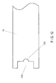
- Rectangular notches 120a allowing fitting of the sockets 102 are formed respectively at both ends of the reflecting panel 120 in the longitudinal direction.
- U-shaped insertion portions 120b and 120c continuing to the notches 120a respectively are formed at edge portions on the sides where the notches 120a face the sockets 102.
- the straight tube fluorescent lamp, not illustrated is removed from the existing apparatus body 100, and the reflecting panel 120 is removed. Subsequently, the lighting apparatus, not illustrated, for performing the lighting control of the existing straight tube fluorescent lamp is removed, and the lighting apparatus 108 for performing the lighting control of the tube lamp 30 is mounted within the apparatus body 100. At this time, the lead wire drawn from the lighting apparatus 108 is connected to the terminal bed 110. Then, the U-shaped insertion portions 120b and 120c are formed at the both ends of the reflecting panel 120 in the longitudinal direction by using the tool or the like.
- the connecting wire 104a connected to the lighting apparatus 108 is inserted and disposed so as to be led out from the one insertion portion 120b of reflecting panel 120 and the grounding wire 112a mounted on the apparatus body 100 in electric conduction is inserted and disposed so as to be led out from the other insertion portion 120c of the reflecting panel 120, whereby the reflecting panel 120 is mounted on the apparatus body 100.
- the connector 8b of the feeding unit 8 on the lamp body 1 side is connected to the connector 104b provided on the connecting wire 104a on the apparatus body 100 side, and the connector 32b of the grounding portion 32 on the lamp body 1 side is connected to the connector 112b mounted at the distal end of the grounding wire 112a on the apparatus body 100 side. Accordingly, the tube lamp 30 is suspended and supported by the apparatus body 100 via the feeding wire and the grounding wire connected to the both ends thereof.
- the bases 6 at the both ends of the tube lamp 30 are mounted on the sockets 102. Then, mounting of the tube lamp 30 with respect to the apparatus body 100 is completed. Accordingly, power is supplied from the feeding unit 8 to the tube lamp 30 and the tube lamp 30 is supported by the sockets 102 so that the mounted state can be held. Depending on the state of deterioration of the sockets 102, the sockets 102 may be replaced simultaneously with the replacement of the tube lamp 30.
- the lighting apparatus 108 is connected to the commercial AC power supply AC, and the output from the lighting apparatus 108 is supplied to the LEDs 2.
- the LEDs 2 As is clear from FIG. 16 , there is no component electrically connected to the pins 6b projecting from the both ends of the lamp body 1, and no power is supplied to the lamp body 1 via the bases 6.
- the plurality of LEDs 2 are energized and the respective LEDs 2 are lit.
- the light emitted from the LEDs 2 pass through the cover 1a, and is radiated downward whereby a predetermined range is illuminated.
- the connecting wire 104a at the power source side that is, for connecting the apparatus body 100 and the feeding unit 8 of the lamp body 1 is led out from the insertion portion 120b formed continuously with the notches 120a of the reflecting panel 120 for fitting the sockets 102.
- the connecting wire 104a led out from the apparatus body 100 is wired along the one socket 102.
- the connecting wire 104a, the connector 104b, the connector 8b, and the feeding wire 8a which constitute the feeding wire 9 are hidden inside the socket 102 and hence do not show up, and hence good appearance is achieved.
- the connecting wire 104a, the connector 104b, the connector 8b and the feeding wire 8a are arranged on the back side of the tube lamp 30, these members do not become an obstacle of light emitted from the LEDs 2.
- the connecting wires 104a, 8b formed of a synthetic resin material are hidden on the back side of the tube lamp 30, the dose of the UV-ray radiation may be reduced by a long term use of the tube lamp 30, so that the deterioration of the connector due to the UV ray can be inhibited.
- the effects obtained by the insertion portion 120b described above may be the same for the insertion portion 120c on the grounding portion side as well.
- the apparatus body 100 has been used already for a long time to some extent.
- the apparatus body 100 for mounting the tube lamp 30 is used for a long time, there is a probability of deterioration of the sockets 102 due to the influence of, in particular, heat or UV-ray. Therefore, when the tube lamp 30 is mounted on the sockets 102 of the apparatus body 100 deteriorated in this manner, the bases 6 of the tube lamp 30 may come apart from the sockets 102 due to vibrations or the like, and the tube lamp 30 may drop.
- the bases 6 portion of the tube lamp 30 come apart from the sockets 102, one end of the tube lamp 30 is connected by the feeding unit 8, whereby the dropping may be prevented.
- the grounding portion 32 is connected to the other end of the tube lamp 30, the both end sides thereof are supported in cooperation with the feeding unit 8, and the further safety may be secured.
- the feeding wire 8a of the feeding unit 8 and the grounding wire 32a of the grounding portion 32 are adjusted to the substantially same length.
- the feeding unit 8 Since the feeding unit 8 is arranged in the vicinity of the position near the end portion of the lamp body 1 of the tube lamp 30, it does not show up in appearance, and then the feeding wire 8a can be reduced.
- the grounding portion 32 is connected to the thermal radiating unit 11b of the lamp body, even though the insulating properties of the substrates 4 where the LEDs 2 are mounted are deteriorated whereby the insulating properties between the substrates 4 and the thermal radiating unit 1b and the current is leaked to the thermal radiating unit 1b, risk of the electric shock may be prevented at the time of the maintenance such as cleaning or the replacement of the tube lamp 30 since the thermal radiating unit 1b is grounded.
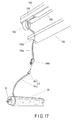
- FIG. 17 is a partly enlarged perspective view illustrating a principal portion of the luminaire according to a fourth embodiment.
- the components which function in the same manner as the luminaire of the third embodiment described above are designated by the same reference signs, and the detailed description is omitted.
- This embodiment is characterized in that the insertion portion 120b for inserting the connecting wire 104a led out from the apparatus body 100 side is provided on the sockets 102 instead of the reflecting panel 120.
- the insertion portion 120b is configured by a depression formed inside the sockets 102. This depression is formed into a substantially semi-cylindrical shape so as to allow the passage of the connecting wire 104a connected to the lighting apparatus 108 and, more specifically, forms the insertion portion 120b with the rectangular notches 120a formed on the reflecting panel 120.
- the insertion portion 120c configured to allow insertion of the grounding wire 112a led from the apparatus body 100 is also formed inside the socket 102.
- the feeding wire and the grounding wire can be wired along the sockets 102, and hence the lead wire and the connectors are not seen from the front side of the luminaire, so that the appearance is improved.
- FIG. 18 to FIG. 25 a luminaire 500 according to a fifth embodiment will be described.
- the components which function as those in the first to fourth embodiments are designated by the same reference signs, and detailed description may be omitted.
- FIG. 18 illustrates an appearance perspective view of the luminaire 500 of this embodiment
- FIG. 19 illustrates a side view of the luminaire 500 viewed from the side.
- the luminaire 500 includes the apparatus body 100 to be installed on the ceiling surface or the like of the building and a tube lamp 50 to be mounted on the apparatus body 100.
- the apparatus body 100 in which the existing straight fluorescent lamp has been mounted, has a structure which allows the straight fluorescent lamp to be replaced by the tube lamp 50.
- the apparatus body 100 is configured in such a manner that the tube lamp 50 is mounted between the two sockets 102 by connecting the two bases 6 at the both ends of the tube lamp 50 to the two sockets 102 mounted at the both ends in the longitudinal direction.
- the tube lamp 50 of this embodiment includes the same dimensions and outlines as the existing straight tube fluorescent lamp. More specifically, the tube lamp 30 has the same dimensions and the outline as the straight fluorescent lamp of 40W.
- the tube lamp 50 also has the substrate 4 on which the plurality of LEDs 2 are mounted in the lamp body 1 being elongated and having a substantially cylindrical shape, the two bases 6 at the both ends of the lamp body 1, and the feeding unit 8 on the lamp body 1.
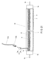
- the lamp body 1 is formed by extrusion of the translucent synthetic resin material, includes an outline of substantially cylindrical shape, and has an internal space in which the plurality of the LEDs 2 are arranged. Then, a storage depression 52 having a substantially angular U-shape in cross section and in a groove shape is formed along the longitudinal direction on the back side of the lamp body 1.
- the storage depression 52 has a function as a storage portion configured to store the feeding wire and the grounding wire connecting the lamp body 1 and the apparatus body 100.
- the thermal radiating unit 1b having a rectangular shape elongated along the longitudinal direction is provided in the interior space of the lamp body 1.
- the thermal radiating unit 1b is formed of an aluminum material of the like having superior conductivity.
- Adhered to the front side of the thermal radiating unit 1b are the elongated substrates 4 having the plurality of LEDs 2 mounted thereon.
- the substrates 4 are formed into a substantially rectangular shape and, more specifically, four of the substrates 4 are mounted on the thermal radiating unit 1b in line in the longitudinal direction so that the back sides thereof come into tight contact therewith.
- the substrate 4 is formed of a flat plate formed of glass epoxy resin which is an insulating material, and a wiring pattern formed of copper foil is applied on the side of the front surface. Also, a resist layer is applied as needed.
- the insulating material is used as the material of the substrates 4, ceramics materials or synthetic resin materials may be applied.
- the metal it is preferable to apply materials having desirable thermal conductivity and superior in thermal radiating properties like aluminum or the like.
- the light-emitting elements of the embodiment are the LEDs and a surface-mounted LED package.
- the light-emitting element includes an LED chip disposed on a main body formed of ceramics and a translucent resin for molding such as epoxy resin or silicone resin for sealing the LED chip.
- the LED chips are blue LED chips emitting blue light.
- the translucent resin is mixed with phosphor, and yellow phosphor which emits yellowish light which is in a compensating relationship with the blue light is employed in order to allow emission of white light.
- the LEDs 2 may be configured by mounting LED chips directly on the substrate 4, or by mounting bombshell-shaped LEDs 2 thereon.
- the method or the form of mounting the LEDs is not specifically limited. In the embodiment, four each of the LEDs 2 are mounted linearly along the longitudinal direction on one of the substrates 4.
- the bases 6 are, for example, a G13-type base, and are configured to be mountable on the sockets 102 of the luminaire 500 where the existing straight fluorescent lamp is mounted, and are securely provided at the both ends of the lamp body 1.
- the bases 6 each include a pair of the pins 6b so as to project integrally from the bottom of the bases 6a.
- the bases 6 are formed of a metal, and the pair of pins 6b are configured to be electrically insulated.
- the pins 6b are not electrically connected to the LEDs 2.
- the bases 6 are electrically opened, and even when power is supplied to the pins 6b, the electric current does not flow to the pins 6b. Therefore, as described later, when the bases 6 are connected to the sockets 102 of the apparatus body 100 of the luminaire 500, electrical conduction does not occur, and the function to support the tube lamp 50 by the apparatus body 100 simply is achieved.
- the pins 6b may be formed of an insulating material or may be coated with an insulating material. In this case, the double safety is secured coupled with the fact that the pair of 6b are configured to be in the electrically insulated state.
- the feeding unit 8 is connected to the power supply side, that is, the apparatus body 100 side, and has a function to supply the electric power to the LEDs 2 through the substrates 4.
- the feeding unit 8 of this embodiment includes the connector 8b and the feeding wire 8a having the connector 8b at one end thereof, and is disposed so as to lean on one side of the lamp body 1 in the longitudinal direction (left end in FIG. 20 , for example).
- the connector 8b is provided at the distal end of the feeding wire 8a, is formed of a synthetic resin material, and is configured to be connected electrically and mechanically to the connector 104b provided at the distal end of the connecting wire 104a, described later, led out from the apparatus body 100 side.
- the connectors 3a electrically connected to the wiring pattern on the substrates 4, and electrically connected to the LEDs 2.
- the connectors 3a pass through a through hole formed on the thermal radiating unit 1b and project to the back side of the thermal radiating unit 1b.
- a proximal end of the feeding wire 8a of the feeding unit 8 is firmly connected to the connectors 3a.
- the feeding wire 8a led out from the connectors 3a to the back side is led out to the back side of the lamp body 1 through the through hole formed on the bottom of the storage depression 52.
- Part of the feeding wire 8a may be fixed to the lamp body 1 by a tensile force stopper, not illustrated. Accordingly, direct application of the stress to be applied to the feeding wire 8a on the connecting portion with respect to the connectors 3a is avoided.
- the connector 8b of the feeding unit 8 may be fixed to the storage depression 52.
- the connector 8b of the feeding unit 8 may be provided directly to the back side of the substrates 4 without providing the feeding wire 8a. In this case, the feeding unit 8 is configured of the connector 8b.
- the apparatus body 100 is formed into a box shape having an opening portion opened on a lower side, and includes the sockets 102 mounted at the both ends thereof, the lighting apparatus 108 and the terminal bed 110 stored in the apparatus body 100, and the reflecting panel 120 mounted so as to cover the opening portion on the lower surface side.
- the sockets 102 are provided with feed terminals connecting the two pins 6b of the bases 6 at the both ends of the tube lamp 50. However, the feed terminal of the sockets 102 is not connected to the bases 6 of the tube lamp 50 electrically, and is opened electrically.
- the lighting apparatus 108 is connected to a commercial AC power source AC, and generates a DC output upon reception of the commercial AC power source AC.
- the lighting device 108 is configured by connecting a smoothing capacitor between the output terminals of a full-wave rectifying circuit, and connecting a DC voltage converting circuit and current detecting means to the smoothing capacitor.
- the connecting wire 104a is led out from the lighting apparatus 108, and the connector 104b is provided at a distal end of the connecting wire 104a.
- the connector 104b is configured to be electrically and mechanically connected with respect to the connector 8b of the feeding unit 8 on the lamp body 1.
- the reflecting panel 120 is formed with the penetrating circular insertion portion 120a ( FIG. 18 ) for allowing insertion of the connecting wire 104a drawn out from the lighting apparatus 108.
- the insertion portion 120a is disposed with a bush as a wiring protecting material. Also, the insertion portion 120a is provided with a tensile force stopper 130 ( FIG. 19 ) for fixing the connecting wire 104a to the apparatus body 100.
- the connecting wire 104a and the connector 104b passed through the insertion portion 120a, and the feeding unit 8 connected to the connector 104b are configured to be stored in the storage depression 52 provided on the back side of the lamp body 1. Therefore, the projection or protrusion of the feeding wire or the connector from the outer shell of the lamp body 1 may be reduced, and the wiring process may be performed cohesively.
- FIG. 22 and FIG. 23 a state in which the feeding wire 8a and the connector 8b are stored in the storage depression 52 is illustrated.
- the terminal bed 110 is configured to allow connection of the power supply wires and earth wires, not illustrated, from the outside of the apparatus body 100.
- the lighting apparatus 108 is connected to the terminal bed 110 via the lead wire.
- the straight tube fluorescent lamp, not illustrated is removed from the existing apparatus body 100, and the reflecting panel 120 is removed. Subsequently, the lighting apparatus, not illustrated, for performing the lighting control of the existing straight tube fluorescent lamp is removed, and the lighting apparatus 108 for performing the lighting control of the tube lamp 50 is mounted within the apparatus body 100. At this time, the lead wire drawn from the lighting apparatus 108 is connected to the terminal bed 110. Also, at this time, the insertion portion 120a is formed on the reflecting panel 120 using a tool or the like.
- the connecting wire 104a connected to the lighting apparatus 108 is passed through the insertion portion 120a of the reflecting panel 120, and the reflecting panel 12 is mounted to the apparatus body 100.
- the connecting wire 104a and the connector 104b of the connecting portion 104 are brought into a state of being led toward the front of the apparatus body 100.
- the connector 8b of the feeding unit 8 on the lamp body 1 side is connected to the connector 104b provided at the distal end of the connecting wire 104a drawn from the apparatus body 100, and a series of feeding wire 9 composed of the connecting wire 104a, the connector 104b, the feeding wire 8a, and the connector 8b is disposed so as to be stored in the storage depression 52 provided on the back side of the lamp body 1.
- the bases 6 at the both ends of the tube lamp 50 are mounted on the sockets 102, respectively. Then, mounting of the tube lamp 50 with respect to the apparatus body 100 is completed.
- the feeding wire 9 is stored in the storage depression 52, and is inhibited from protruding unintentionally.
- the storage depression 52 is provided along the longitudinal direction, the elongated feeding wire 9 is disposed along the storage depression 52, and the storage is easily achieved.
- the tube lamp 50 When the tube lamp 50 is mounted on the apparatus body 100 as described above, power is supplied from the feeding unit 8 to the tube lamp 50 and the tube lamp 50 is supported by the sockets 102 so that the mounted state can be held. Depending on to the state of deterioration of the sockets 102, the sockets 102 may be replaced simultaneously with the replacement of the tube lamp 50.
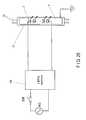
- the lighting apparatus 108 is connected to the commercial AC power supply AC, and the output from the lighting apparatus 108 is supplied to the LEDs 2.
- the LEDs 2 As is clear from FIG. 25 , there is no component electrically connected to the two pins 6b projecting from the both ends of the lamp body 1, and no power is supplied to the lamp body 1 via the bases 6.
- the plurality of LEDs 2 are energized via the connecting wire 104a, the connector 104b, the connector 8b, the feeding wire 8a, and the substrates 4 and the respective LEDs 2 are lit.
- the light emitted from the LEDs 2 passes through the translucent lamp body 1, and is radiated downward whereby a predetermined range is illuminated.
- the feeding wire 9 including the connecting wire 104a, the connector 104b, the connector 8b, and the feeding wire 8a connected each other is stored in the storage depression 52 provided on the back side of the lamp body 1. Therefore the feeding wire 9 is prevented from projecting or protruding from the outer shell of the lamp body 1, so that the wiring process may be performed cohesively.
- the feeding wire 9 is stored in the storage depression 52 on the back side of the tube lamp 50, therefore, the feeding wire 9 does not become the obstacle of radiation of light from the LEDs 2 or reflecting light from the reflecting panel 120.
- the connectors 8b, 104b formed of a synthetic resin material are stored and arranged in the storage depression 52, therefore, the dose of the UV-ray to be radiated on these connectors may be reduced to substantially zero by a long term use of the tube lamp 50, so that the deterioration of the connector due to the UV ray can be inhibited.
- the apparatus body 100 has been used already for a long time to some extent.
- the apparatus body 100 for mounting the tube lamp 50 is used for a long time, there is a probability of deterioration of the sockets 102 due to the influence of, in particular, heat or UV-ray. Therefore, when the tube lamp 50 is mounted on the sockets 102 of the apparatus body 100 deteriorated in this manner, the bases 6 of the tube lamp 50 may come apart from the sockets 102 due to vibrations or the like, and the tube lamp 50 may drop.
- FIG. 24 a modification of the fifth embodiment described above is illustrated.
- the cap mounting portions 54 are provided at both sides of the opening in the storage depression 52 so as to prevent the feeding wire 9 from coming apart from the opening on the back side hereof. In this manner, with the provision of the cap mounting portions 54 at an edge of the opening of the storage depression 52, the storage of the feeding wire 9 in the storage depression 52 is ensured.
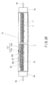
- a tube lamp 60 according to a sixth embodiment will be described with reference to FIG. 26 .
- the components which function in the same manner as the fifth embodiment described above are designated by the same reference signs, and the detailed description is omitted.
- the tube lamp 60 in this embodiment is characterized by the structure in which the feeding wire 8a of the feeding unit 8 and the grounding wire 32a of the grounding portion 32 are drawn out together from the back side of the lamp body 1.
- the proximal end portion of the grounding wire 32a is fixed by a screwing to the back side of the thermal radiating unit 1b.
- the proximal portion of the feeding wire 8a is connected to the substrates 4 via the connectors 3a described above.
- the distal end of the grounding wire 32a is connected to the connector 8b of the feeding unit 8 together.
- the feeding wire 8a for supplying power and the grounding wire 32a for grounding the tube lamp 60 are connected to the connector 8b, and these are configured to be connected by the single connector 8b. Therefore, the connecting operation of the feeding unit 8 and the grounding portion 32 can be performed at once.
- the grounding wire 32a is stored in the storage depression 52 simultaneously. Since the storage depression 52 is formed on the back side of the lamp body 1, the configurations of the feeding unit 8 and the grounding portion 32 are prevented from projecting or protruding from the shell of the lamp body 1, and the wiring process may be performed cohesively.
- a tube lamp 70 according to a seventh embodiment will be described with reference to FIG. 27 and FIG. 28 .
- the components which function in the same manner as the fifth embodiment described above are designated by the same reference signs, and the detailed description is omitted.
- the tube lamp 70 in this embodiment being different from the first to the sixth embodiments described above, is of a type distributing power via the bases 6 at the both ends of the lamp body 1.
- the power is distributed through the terminal of the sockets 102 in a state of being mounted on the apparatus body 100 in the same manner as the straight tube fluorescent lamp of the related art.
- the grounding wire 32a of the grounding portion 32 is configured to be stored in the storage depression 52.
- the storage depression 52 is provided on the back side of the lamp body 1.
- the grounding portion 32 of the lamp body 1 side has the grounding wire 32a and a connector 32b.
- the proximal end potion of the grounding wire 32a is fixedly fastened to the thermal radiating unit 1b having conductivity in the lamp body 1 with the screw or the like.
- the connector 32b of the grounding portion 32 of the lamp body 1 side is connected the connector 112b provided at the distal end of the grounding wire 112a drawn from the apparatus body 100.
- the earth terminal of the terminal bed 110 electrically connected to the conductive thermal radiating unit 1b is grounded via an earth wire, not shown. Therefore, the lamp body 1 is grounded via the grounding wire 32a, the connector 32b, the grounding wire 112a, the connector 112b, the thermal radiating unit 1b, the terminal bed 110, and the earth wire.
- the grounding wire 32a and the connector 32b of the grounding portion 32 on the lamp body 1 side the grounding wire 112a and the connector 112b led from the apparatus body 1 side can be stored in the storage depression 52 provided on the back side of the lamp body 1. Accordingly, the grounding wire connecting the lamp body 1 and the apparatus body 100 is prevented from projecting and protruding from the outer shell of the lamp body 1.
- the wiring process can be performed cohesively.
- the tube lamp is not limited to a mode compatible with the straight tube fluorescent lamp.
- a mode compatible with a single base type fluorescent lamp is also applicable.
- the lighting apparatus 108 configured to perform the lighting control of the LEDs 2 may be disposed on the apparatus body 100 side or the lamp body 1 side.
Abstract
Description
- Embodiments of the present invention relates to a tube lamp which can be used instead of a tube fluorescent lamp and uses, for example, LEDs as light sources, and to a luminaire using the tube lamp.
- In recent years, LEDs (light-emitting diodes) having a high output and high light-emitting efficiency are now in widespread use, and development of luminaire using the LEDs as light sources regardless of whether the lamp is for indoor or outdoor is in progress. The luminaire using the LEDs has a long service life and consumes less power in comparison with existing luminaire such as fluorescent lamps. Therefore, running cost is low and the number of times of replacement of equipment or maintenance on the basis of service life can be reduced.
- For example, a straight tube lamp using LEDs arranged in a row as light sources, which can be used by being replaced instead of existing straight tube fluorescent lamp is in widespread use.
- [PTL1]
JP-A-2001-351402 - However, since the tube lamp using the current LEDs has a structure to be mounted and feed power by inserting bases provided at both ends thereof into sockets on an apparatus body side, it is necessary to provide a complicated circuit configuration on a lamp side in conformity to a lighting system on the apparatus body side. Therefore, the cost of the lamp is inevitably increased.
- Also, a force of the sockets of the existing apparatus body to hold the bases may be weakened due to aging degradation, and there is a risk of dropping of the tube lamp, and electrical connection may result in a higher rate of unstable electric connection.
- Therefore, development of a tube lamp which provides a high compatibility with existing straight tube fluorescent lamps, can be manufactured by itself at low cost, and has no fear of dropping from the apparatus body, and a luminaire using such a tube lamp is desired.
- A tube lamp of an embodiment comprising: an elongated cylindrical lamp body having translucency; a plurality of light-emitting elements arranged in the lamp body; two mounting portions configured to mount both ends of the lamp body in the longitudinal direction respectively to sockets of an apparatus body;
and a feeding unit provided on the lamp body separately from the two mounting portions for feeding power to the light-emitting element. - In an embodiment, a tube lamp which provides a high compatibility with existing straight tube fluorescent lamps, can be manufactured by itself at low cost, and has no fear of dropping from the apparatus body, and a luminaire using such a tube lamp can be provided.
-
-
FIG. 1 is a cross-sectional view of a tube lamp according to a first embodiment taken along a tube axis. -
FIG. 2 is a cross-sectional view of the tube lamp inFIG. 1 taken along a plane orthogonal to the tube axis. -
FIG. 3 is a cross-sectional view of the tube lamp inFIG. 2 , illustrating a state in which a connector of a feeding unit is fixedly provided on a lamp body. -
FIG. 4 is a cross-sectional view of a tube lamp according to a second embodiment taken along a tube axis. -
FIG. 5 is a schematic view of a luminaire in which the tube lamp inFIG. 1 orFIG. 4 is mounted on an apparatus body. -
FIG. 6 is a schematic view illustrating a state in which a base of the tube lamp comes off from one of sockets of the apparatus body inFIG. 5 . -
FIG. 7 is a circuit diagram of the luminaire inFIG. 5 . -
FIG. 8 is an appearance perspective view illustrating a luminaire according to a third embodiment. -
FIG. 9 is a side view of the luminaire inFIG. 8 viewed from a side. -
FIG. 10 is an exploded perspective view of the luminaire inFIG. 8 . -
FIG. 11 is a perspective view for explaining a connecting state of a feeding unit of the luminaire inFIG. 10 . -
FIG. 12 is a partly enlarged plan view of a principal portion of a reflecting panel integrated in the luminaire inFIG. 10 . -
FIG. 13 is a partly enlarged perceptive view of an end portion of the tube lamp inFIG. 10 on the power feeding side. -
FIG. 14 is a cross-sectional view of the tube lamp inFIG. 10 taken along the tube axis thereof. -
FIG. 15 is a cross-sectional view taken along the line F15-F15 inFIG. 14 . -
FIG. 16 is a circuit diagram of the luminaire inFIG. 8 . -
FIG. 17 is a partly enlarged perspective view illustrating the structure of a principal portion of a luminaire according to a fourth embodiment. -
FIG. 18 is an apparent perspective view illustrating a luminaire according to a fifth embodiment. -
FIG. 19 is a side view of the luminaire inFIG. 18 when viewed from a side. -
FIG. 20 is a partly enlarged perspective view illustrating a principal portion of the tube lamp of the luminaire inFIG. 18 . -
FIG. 21 is a cross-sectional view of the tube lamp inFIG. 20 taken along a tube axis. -
FIG. 22 is a cross-sectional view of the tube lamp inFIG. 21 illustrating a state in which a feed wire of the tube lamp inFIG. 21 is stored in a storage portion. -
FIG. 23 is a cross-sectional view taken along the line F23-F23 inFIG. 22 . -
FIG. 24 is a cross-sectional view of a modification of the tube lamp inFIG. 23 . -
FIG. 25 is a circuit diagram of the luminaire inFIG. 18 . -
FIG. 26 is a cross-sectional view of a tube lamp according to a sixth embodiment taken along a tube axis. -
FIG. 27 is a cross-sectional view of a tube lamp according to a seventh embodiment taken along a tube axis. -
FIG. 28 is a cross-sectional view of the tube lamp inFIG. 27 illustrating a state in which a grounding wire of the tube lamp inFIG. 27 is stored in a storage portion. - Referring now to the drawings, an embodiment will be described in detail.
-
FIG. 1 illustrates a cross-sectional view of atube lamp 10 according to a first embodiment taken in a longitudinal direction along a tube axis thereof.FIG. 2 shows a cross-sectional view of thetube lamp 10 taken along a plane orthogonal to the tube axis thereof. In the respective embodiments describe below, a straight tube lamp having a substantially cylindrical shape extending straight as illustrated inFIG. 1 will be described as an example of tube lamps. - The
tube lamp 10 has a structure which can be used instead of an existing straight tube fluorescent lamp (not illustrated). In other words, thetube lamp 10 in this embodiment can be used by being mounted on an apparatus body 100 (described in detail later) of a luminaire configured to be used by mounting the straight tube fluorescent lamp in the related art. - The
tube lamp 10 in this embodiment includes an elongated straighttube lamp body 1 of a substantially cylindrical shape, a plurality (eight in this embodiment) of LEDs 2 (light-emitting elements) arranged in a line in the longitudinal direction in the ,lamp body 1, twosubstrates 4 on which the plurality ofLEDs 2 are mounted, two bases 6 (mounting portion) mounted respectively on both ends of thelamp body 1 in the longitudinal direction for mounting thelamp body 1 on theapparatus body 100, andfeeding unit 8 configured to feed power to eight of theLEDs 2. - The
tube lamp 10 in this embodiment is characterized by a structure in which a plurality of theLEDs 2 are disposed side by side along the direction of an tube axis, and eight of theLEDs 2 are mounted on the twosubstrates 4, that is, four on each of thesubstrates 4, respectively. Thefeeding unit 8 is provided on the back side of thelamp body 1 in the direction in which thetube lamp 10 faces theapparatus body 100. - The
lamp body 1 includes atranslucent cover 1a, and a thermal radiatingunit 1b formed of an aluminum extruded material. Thecover 1a has a shape obtained by cutting a substantially cylindrical shape along a center line thereof, and includesengaging edge portions 1c extending in the longitudinal direction for engaging the thermal radiatingunits 1b at both side edge portions facing the thermalradiating unit 1b. The material of thecover 1a is preferably a material which can diffuse light. - In contrast, the thermal radiating
unit 1b includesengaging step portions 1d extending in the longitudinal direction for allowingengaging edge portions 1c of thecover 1a to be fitted thereto. In a case where thelamp body 1 is assembled by fitting thecover 1a and the thermal radiatingunit 1b, thecover 1a is slid in the longitudinal direction to engage theengaging edge portions 1c and theengaging step portions 1d. - The thermal radiating
unit 1b integrally includes amounting base 1e for mounting thesubstrates 4 on which theLEDs 2 are mounted, and a plurality of thermal radiatingfins 1f extending upright from a back side (upper side inFIG. 2 ) of themounting base 1e. The material of the thermal radiatingunit 1b is preferably a metallic material having high thermal efficiency. - Provided in the vicinities of the end portions of the two
substrates 4 facing each other areconnectors 3a for connecting afeeding wire 8a respectively. Formed on the mountingbase 1e located in a gap between the twosubstrates 4 is alead hole 1g penetrating therethrough for leading out thefeeding wire 8a connected to theconnectors 3a from the back side of thelamp body 1 to the outside. Thefeeding wire 8a led via thelead hole 1g is drawn out to the back side of thelamp body 1 from between thethermal radiating fins 1f. - The two
bases 6 are provided so as to support both ends of thelamp body 1 respectively with respect to theapparatus body 100 of the luminaire to which the existing straight tube fluorescent lamp (not illustrated) can be mounted as illustrated inFIG. 5 and FIG. 6 . In other words, thelamp body 1 is mounted on theapparatus body 100 by mounting the twobases 6 located at the both ends thereof to twosockets 102 of theapparatus body 100, respectively. - The two
bases 6 have a strength enough to support the own weight of thelamp body 1. Each of the twobases 6 integrally includes a bottomed cylindrical shapedcap 6a (fixture) to be mounted at an end portion of thelamp body 1 and twopins 6b (connectors) projecting from the bottom of thecap 6a. The twopins 6b are connected to terminals of thesockets 102 of theapparatus body 100. The shape of the terminals of thebases 6 is determined according to the shape of the terminals of thesockets 102 on theapparatus body 100 side. - The
cap 6a and thepins 6b are formed respectively of a metal. In other words, the twobases 6 have thermal conductivity, respectively. Then, the twobases 6 are mounted respectively to the both ends of thelamp body 1 by bonding thecaps 6a to the end portions of thelamp body 1 by caulking or with an adhesive agent such as a resin. - However, the
bases 6 in this embodiment is not provided as feed terminals for feeding electricity from theapparatus body 100 side to thelamp body 1, and is simply be provided for mounting thelamp body 1 to theapparatus body 100. - Therefore, the
bases 6 are connected to thesockets 102 of theapparatus body 100 in an insulated state. Alternatively, the twopins 6b of thebases 6 are connected to thecaps 6a in the insulated state. Alternatively, the twopins 6b of therespective bases 6 are in the insulated sate with respect to each other. - In other words, the
bases 6 are electrically opened, and even when electricity is supplied to the twopins 6b from the side of theapparatus body 100 to the twopins 6b via thesockets 102, theLEDs 2 in thelamp body 1 are not energized via thebases 6. In other words, when an attempt is made to mount thetube lamp 10 in this embodiment to the existingapparatus body 100, it is necessary to provide thefeeding unit 8 for feeding electricity to the plurality ofLEDs 2 separately from the twobases 6. - The
feeding unit 8 is provided on thelamp body 1 for connecting thelamp body 1 to an external power supply for supplying power to theLEDs 2. More specifically, thefeeding unit 8 includes thefeeding wire 8a connected to theconnectors 3a mounted on thesubstrates 4 and aconnector 8b provided at a distal end of thefeeding wire 8a. - The
feeding wire 8a is led out from the back side of thelamp body 1 via thelead hole 1g of thethermal radiating unit 1b, and in a midcourse thereof, is fixed to thelamp body 1 by a tensile force stopper or the like, not illustrated here. In this manner, by fixing thefeeding wire 8a to thelamp body 1 by the tensile force stopper or the like, a stress applied to thefeeding wire 8a is prevented from being applied to connecting portions with respect to theconnectors 3a on thesubstrates 4. For example, even when thefeeding wire 8a is pulled, application of an unintended force to theconnectors 3a is prevented. - Alternatively, in order to eliminate the stress applied to the
feeding wire 8a, fixation may be achieved by storing thefeeding wire 8a in thelamp body 1, and fixing theconnector 8b to thelamp body 1 by direct mount. In this case, for example, as illustrated inFIG. 3 , theconnector 8b of thefeeding unit 8 is secured to the back side of the mountingbase 1e between thethermal radiating fins 1f. - The feeding unit 8 (the
feeding wire 8a and theconnector 8b) is provided on the back side in the direction in which thelamp body 1 faces theapparatus body 100. Therefore, in a state in which thelamp body 1 is mounted on theapparatus body 100, thefeeding wire 8a and theconnector 8b are hidden on the back side of thelamp body 1, and thefeeding wire 8a and theconnector 8b can hardly be seen from the front side of the luminaire, that is, from the side where illuminating light is extracted. - In contrast, a connecting
portion 104 on theapparatus body 100 side for connecting thefeeding unit 8 of thelamp body 1 to theapparatus body 100 includes aconnector 104b to be connected to theconnector 8b of thefeeding unit 8 and a connectingwire 104a having theconnector 104b at one end thereof. Thefeeding wire 8a and the connectingwire 104a connected via theconnectors feeding wire 9 for feeding power to the plurality ofLEDs 2. - As described above, the
translucent cover 1a and thethermal radiating unit 1b define a space for disposing theLEDs 2 in the interior of thelamp body 1. In other words, the outline of thelamp body 1 has a substantially cylindrical shape, and thecover 1a provides at least part of thelamp body 1 with translucency. In contrast, theLEDs 2 disposed in thelamp body 1 face the inner surface of thecover 1a. Therefore, when theLEDs 2 are lit, light radiated from theLEDs 1 is radiated from the front of thetube lamp 10 via thecover 1a. - According to the
tube lamp 10 of the embodiment, theLEDs 2 are lit by receiving a supply of power from the outside via thefeeding unit 8. In other words, thebases 6 at the both ends of thelamp body 1 are provided only for causing thesocket 102 of theapparatus body 100 to support thelamp body 1. Therefore, according to the present embodiment, irrespective of the lighting method of the existing luminaire, thetube lamp 10 which can supply desired power to thelamp body 1 via thefeeding unit 8, and enhance general versatility is provided. - According to the present embodiment, even though the
sockets 102 of theapparatus body 100 of the existing luminaire is subjected to aging degradation, since the supply of power through thefeeding unit 8 provided separately from thebases 6 is possible, reliability of electrical connection can be secured. - In contrast, when the
sockets 102 are subjected to the aging degradation, there is a risk of dropping of thetube lamp 10. However, in this embodiment, since thelamp body 1 and theapparatus body 100 are connected via thefeeding wire 9, even when thebases 6 come apart from thesockets 102, there is no risk of dropping of thelamp body 1. - Furthermore, according to this embodiment, since the
feeding unit 8 is led out from the vicinity of the center of thelamp body 1 in the direction of the tube axis as illustrated inFIG. 1 , when mounting thebases 6 of thetube lamp 10 to thesockets 102 of theapparatus body 100, thefeeding wire 8a or theconnector 8b of thefeeding unit 8 can hardly interfere with thebases 6 and thesockets 102. Therefore, even though thefeeding wire 8a is led out from thelamp body 1, the mounting workability of thelamp body 1 may be facilitated. -
FIG. 4 illustrates a cross-sectional view of atube lamp 20 according to a second embodiment. - The
tube lamp 20 has the same structure as the above-described first embodiment except that alighting circuit 12 is mounted in thelamp body 1. Therefore, the components which function in the same manner as the first embodiment described above are designated by the same reference signs, and the detailed description is omitted. - As illustrated in
FIG. 4 , in thetube lamp 20 of this embodiment, thelighting circuit 12 is mounted on the back side of thesubstrates 4, and thefeeding wire 8a of thefeeding unit 8 is drawn out from thelighting circuit 12. Then, theconnector 8b of thefeeding unit 8 is connected to a commercial power supply, not illustrated here. In other word, the commercial power is supplied to thelighting circuit 12. - The
lighting circuit 12 generates a lighting power for lighting theLEDs 2 from the supplied commercial power, and supplies the same to theLEDs 2. In this embodiment, thelighting circuit 12 is disposed in thelead hole 1g of the mountingbase 1e, an thefeeding wire 8a of thefeeding unit 8 is led out from near the center of thelamp body 1 in the direction of the tube axis to the outside. In this case, the shape and the size of thelead hole 1g is set so as to be in conformity to thelighting circuit 12. - In this case, the power supplied to the
feeding unit 8 is not specifically limited. However, when supplying the commercial power at a rating of 200V or higher, a configuration in which thetube lamp 20 side and the commercial power supply side can be brought into an earth connection by connecting theconnector 8b of thefeeding unit 8 with the commercial power supply is preferable. - In this manner, since a configuration in which the commercial power is supplied to the
feeding unit 8 of thetube lamp 20 is employed, when the existing fluorescent lamp of the luminaire using the straight fluorescent lamp already set is replaced by thetube lamp 20 in this embodiment, a burden imposed at the time of replacement is reduced. - Also, for example, when replacing the
tube lamp 10 having different circuit configuration such as the difference in rating, replacement is easily achieved if the connectingportion 104 for supplying power from theapparatus body 100 side to thefeeding unit 8 is led out. - Also, the
lighting circuit 12 to be disposed in thetube lamp 20 may be part of the lighting circuit for lighting control of theLEDs 2. In other words, thetube lamp 20 is supported by thesockets 102 configured to hold the fluorescent lamp of the related art, and therefore, the lighter weight is preferable. - Accordingly, by disposing the common circuit portion on the
apparatus body 100 side and disposing only part of the lighting circuit on thelamp body 1, the light weight of thetube lamp 20 is achieved and the burden imposed at the time of replacement is also reduced. For example, it may be achieved by disposing a circuit configured to convert the commercial power supply to DC power supply on theapparatus body 100 side, and disposing the circuit configured to supply power from the DC power supply to theLED 2 in thelamp body 1. - In this embodiment, as illustrated in
FIG. 4 , the substrate is composed of asingle substrate 4, and thelighting circuit 12 is mounted on the back side of thesubstrate 4 and thelighting circuit 12 is disposed in thelead hole 1g. However, this embodiment is not limited thereto, and a storage portion for disposing thelighting circuit 12 on the mountingbase 1e may be provided, or thelighting circuit 12 may be disposed on the mounting surface side of thesubstrate 4 where theLEDs 2 are disposed, or may be configured as a member separate from thesubstrate 4. -
FIG. 5 illustrates a schematic drawing of aluminaire 200 with either one of thetube lamps apparatus body 100.
FIG. 6 illustrates a schematic drawing illustrating a state in which one (right side in the drawing) of thebases 6 of thetube lamp sockets 102 from the state illustrated inFIG. 5 . - The
apparatus body 100 of theluminaire 200 includes the twosockets 102 provided respectively at both ends in the longitudinal direction thereof. Therespective sockets 102 are suspended from a lower surface side of theapparatus body 100 at both ends in the longitudinal direction. Thetube lamp sockets 102 and is mounted on theapparatus body 100 by connecting thebases 6 on the both ends to the terminal of thesockets 102. - The
apparatus body 100 includes alighting apparatus 106 which is capable of supplying power to terminals, not illustrated, of thesockets 102. Thelighting apparatus 106 is for a lighting control of the existing straight fluorescent lamp. In other words, since thelighting apparatus 106 is an unnecessary configuration when using thetube lamp lighting apparatus 106 may be removed at the same time as the replacement of thetube lamp lighting apparatus 106 may be retained in theapparatus body 100 as-is. - Furthermore, the
apparatus body 100 includes alighting apparatus 108 for a lighting control of the plurality ofLEDs 2 of thetube lamp wire 104a of the connectingportion 104 described above is connected to thelighting apparatus 108. As described above, theconnector 104b of the connectingportion 104 is connected to theconnector 8b of thefeeding unit 8 on thelamp body 1 side. Then, the power from thelighting apparatus 108 is supplied to thefeeding unit 8 via the connectingportion 104. - The connecting
wire 104a led from theapparatus body 100 is fixed to theapparatus body 100 by atensile force stopper 105 at a midpoint thereof. Accordingly, even when the connectingwire 104a is pulled unintentionally, there is no fear of application of an unintentional stress to the connecting portion of the proximal end portion of theconnector 104b with respect to thelighting apparatus 108. -
FIG. 7 illustrates a circuit diagram of theluminaire 200 described above. - The
lighting apparatus 108 is connected to a plurality of theLEDs 2 via thefeeding wire 9. Thefeeding wire 9 described here includes thefeeding wire 8a and theconnector 8b of thefeeding unit 8 on thelamp body 1 side and the connectingwire 104a and theconnector 104b of the connectingportion 104 on the side theapparatus body 100 as described above. - A commercial
AC power supply 110 is connected to thelighting apparatus 108, and the plurality ofLEDs 2 can be lit and extinguished by turning aswitch 112 ON and OFF. As illustrated inFIG. 7 , no power supply is connected to thebases 6 at the both ends of thelamp body 1 in the longitudinal direction, and electrically opened state is assumed. - A method of replacing the existing straight fluorescent lamp by the above-described
tube lamp FIG. 5 and FIG. 6 . - First of all, the straight tube fluorescent lamp is disconnected from the
apparatus body 100 of theluminaire 200 in a state of being installed on a ceiling surface or the like on the building. Then, thelighting apparatus 108 is mounted on theapparatus body 100. The commercial power supply is connected to thelighting apparatus 108. At this time, theunnecessary lighting apparatus 106 for the fluorescent lamp may be removed from theapparatus body 100. At this time, part of theapparatus body 100 is formed with an insertion hole for leading out the connectingwire 104a. Then, the connectingwire 104a is lead out to the outside from theapparatus body 100 through the insertion hole. Furthermore, the midsection of the connectingwire 104a is fixed to theapparatus body 100 by thetensile force stopper 105. - Subsequently, the
bases 6 at the both ends of thetube lamp respective sockets 102. At this time, simultaneously, theconnector 8b at a distal end of thefeeding wire 8a led out from thetube lamp connector 104b at the distal end of the connectingwire 104a are connected. - In this manner, when mounting the
tube lamp apparatus body 100, by connecting thefeeding unit 8 on thelamp body 1 side and the connectingportion 104 on theapparatus body 100 side, a problem of dropping of thelamp body 1 at the time of mounting thetube lamp lamp body 1 is suspended and supported with respect to theapparatus body 100 via thefeeding wire 9. In this case, since therespective components feeding wire 9 do not interfere with thesockets 102 or thebases 6, mounting of thebases 6 on thesockets 102 is not disturbed. - As described above, when the commercial power is supplied to the
lighting apparatus 108 via theAC power supply 110 in a state in which thetube lamp apparatus body 100, a lighting power is supplied to the plurality ofLEDs 2 via the connectingportion 104 and thefeeding unit 8, and the plurality ofLEDs 2 emit light. - In a method of mounting the tube lamp described above, a case where an operation to connect the
feeding unit 8 and the connectingportion 104 is performed simultaneously with an operation to mount thebases 6 to thesockets 102 is described. However, thefeeding unit 8 and the connectingportion 104 may be configured to be connected automatically by the operation of connecting thebases 6 to thesockets 102. For example, a method of fixing parts of thefeeding unit 8 and the connectingportion 104 to be connected via the connector respectively to thelamp body 1 and theapparatus body 100 to achieve a positional relationship so that the both are connected when thebases 6 is mounted on thesockets 102 is conceivable. According to this method, thefeeding unit 8 and the connectingportion 104 can be connected via the connector by the operation to mount thebases 6 to thesockets 102. - By employing the connecting structure described above, interference of lead wires or connectors of the
feeding unit 8 and the connectingportion 104 with thesockets 102 or thebases 6 is avoided, so that the connecting operation between thefeeding unit 8 and the connectingportion 104 is facilitated. - It is also possible to set the positions to fix the
feeding unit 8 and the connectingportion 104 to one of the ends side of thelamp body 1 and one of thesockets 102 side of theapparatus body 100, and provide mounting structures for mounting thetube lamp apparatus body 100 on the other of the end sides of thelamp body 1 and the other of thesockets 102 to thelamp body 1 and theapparatus body 100, respectively. These mounting structures only have to be the same structure as the connecter connection between thefeeding unit 8 and the connectingportion 104. However, power does not have to be supplied, and only the other side of thetube lamp apparatus body 100. - In this manner, by configuring the
tube lamp apparatus body 100 by the connector connection between thefeeding unit 8 and the connectingportion 104 and the engagement on the basis of the mounting structure at the both ends of thetube lamp sockets 102 are deteriorated and thebases 6 cannot obtain sufficient supporting force from thesockets 102, thetube lamp apparatus body 100. -
FIG. 6 is a drawing illustrating a state in which a support of one (right side in the drawing) of thebases 6 of thetube lamp FIG. 6 , even though at least one of thebases 6 comes apart, thetube lamp feeding unit 8 and the connectingportion 104 and the engagement between theother base 6 and thesockets 102. - In other words, in this case, the
feeding wire 9 support a portion of thelamp body 1 near the center and theother base 6 of thelamp body 1 is supported by thesockets 102. Therefore, even though one of thebases 6 comes apart, dropping of thetube lamp sockets 102 are deteriorated is notified to users. - Since the
feeding unit 8 is led out from the portion of thelamp body 1 in the vicinity of the center along the direction of an tube axis, a load applied to the engaging portion between thefeeding unit 8 and the connectingportion 104 is reduced as illustrated inFIG. 6 , and hence thetube lamp - When the existing straight fluorescent lamp is replaced by the
tube lamp apparatus body 100 has been used already to some extent. If it is used for a long time, there is a risk of dropping of thebases 6 of thetube lamp sockets 102 due to the deterioration of thesockets 102 under the influence of, specifically, heat or UV rays, or due to vibrations or any other reasons. - However, even when the
bases 6 drop from thesockets 102, the probability of dropping of the twobases 6 at the both ends of thelamp body 1 from thesockets 102 simultaneously is low. Normally, either one of those drops first. In this embodiment, it is configured that even though at least one of thebases 6 comes apart, thetube lamp feeding unit 8 and the connectingportion 104 and the engagement between theother base 6 and thesocket 102. Therefore, even when thetube lamp apparatus body 100 of theluminaire 200 which is subjected to aging degradation after a long time of usage, the safety can be ensured. In particular, by configuring that the own weight of thetube lamp feeding unit 8 and the connectingportion 104, the safety is further secured. - Referring now to
FIG. 8 to FIG. 16 , a third embodiment will be described. In the following description, the components which function as those in the first and second embodiments are designated by the same reference signs, and detailed description may be omitted. -
FIG. 8 illustrates an appearance perspective view of aluminaire 300 of this embodiment, andFIG. 9 illustrates a side view of theluminaire 300 viewed from the side.FIG. 10 also illustrates an exploded perspective views of theluminaire 300. Theluminaire 300 of this embodiment also includes theapparatus body 100 to be mounted on the ceiling surface or the like of the building and atube lamp 30 to be mounted on theapparatus body 100. - The
apparatus body 100, in which the existing straight fluorescent lamp has been mounted, has a structure which allows the straight fluorescent lamp to be replaced by thetube lamp 30. In other words, theapparatus body 100 is configured in such a manner that thetube lamp 30 is mounted between the twosockets 102 by mounting the twobases 6 at the both ends of thetube lamp 30 to the twosockets 102 mounted at the both ends of the longitudinal direction. - As illustrated in
FIG. 13 to FIG. 15 , thetube lamp 30 of this embodiment includes the same dimensions and outlines as the existing straight tube fluorescent lamp. More specifically, thetube lamp 30 has the same dimensions and the outline as the straight fluorescent lamp of 40W. Thetube lamp 30 also has thesubstrates 4 on which the plurality ofLEDs 2 are mounted in thelamp body 1 being elongated and having a substantially cylindrical shape in appearance, the twobases 6 at the both ends of thelamp body 1, and thefeeding unit 8 and a groundingportion 32 on thelamp body 1. - The
lamp body 1 includes a semi-cylindricaltranslucent cover 1a and a semi-cylindricalthermal radiating unit 1b. Thethermal radiating unit 1b is formed of an aluminum material by an extruded molding, and includes a plurality of thethermal radiating fins 1f so as to extend upright in the longitudinal direction from the back side of the mountingbase 1e where thesubstrates 4 having theLEDs 2 mounted thereon is mounted. Thecover 1a is mounted on the mountingbase 1e of thethermal radiating unit 1b on the opening side thereof so as to be fitted thereto, and defines a substantially cylindrical outline in cooperation with thethermal radiating unit 1b. - Adhered to the front side of the mounting
base 1e of thethermal radiating unit 1b are theelongated substrates 4 having a plurality ofLEDs 2 mounted thereon. Thesubstrates 4 are formed into a substantially rectangular shape and, more specifically, four of thesubstrates 4 are mounted on the mountingbase 1e of thethermal radiating unit 1b in line in the longitudinal direction so that the back sides thereof come into tight contact therewith. - The
substrate 4 is formed of a flat plate formed of glass epoxy resin which is an insulating material, and a wiring pattern formed of copper foil is applied on the front surface side. Also, a resist layer is applied as needed. When the insulating material is used as the material of thesubstrate 4, ceramics materials or synthetic resin materials may be applied. In addition, when the metal is employed, it is preferable to apply materials having desirable thermal conductivity and superior in thermal radiating properties like aluminum or the like. - The light-emitting elements of the embodiment are the LEDs and a surface-mounted LED package. Schematically, the light-emitting element includes an LED chip disposed on a main body formed of ceramics and a translucent resin for molding such as epoxy-based resin or silicone resin for sealing the LED chip.
- The LED chip is a blue LED chip emitting blue light. The translucent resin is mixed with phosphor, and yellow phosphor which emits yellowish light which is in a compensating relationship with the blue light in order to allow emission of white light.
- The
LEDs 2 may be configured by mounting LED chips directly on thesubstrates 4, or by mounting bombshell-shaped LEDs thereon. The method or the form of mounting the LEDs is not specifically limited. In the embodiment, four each of theLEDs 2 are mounted linearly along the longitudinal direction on one of thesubstrates 4. - The
bases 6 are, for example, a G13-type base, and are configured to be mountable on thesockets 102 of theluminaire 300 where the existing straight fluorescent lamp is mounted, and are securely provided at the both ends of thelamp body 1. Thebases 6 each include a pair of thepins 6b so as to project integrally from the bottom of thecaps 6a. Thebases 6 are formed of a metal, and the pair ofpins 6b are configured to be electrically insulated. Thepins 6b are not electrically connected to theLEDs 2. - In other words, the
bases 6 are electrically opened, and even when power is supplied to thepins 6b, the electric current does not flow to thepins 6b. Therefore, as described later, when thebases 6 are connected to thesockets 102 of theapparatus body 100 of theluminaire 300, electrical conduction does not occur, and the function to support thetube lamp 30 by theapparatus body 100 is achieved. - The
pins 6b may be formed of an insulating material or may be coated with an insulating material. In this case, the double safety is secured coupled with the fact that the pair ofpins 6b are configured to be in the electrically insulated state. - The
feeding unit 8 is connected to the power-supply side, that is, theapparatus body 100 side, and has a function to supply the electric power to theLEDs 2 through thesubstrates 4. Thefeeding unit 8 of this embodiment includes theconnector 8b and thefeeding wire 8a having theconnector 8b at one end thereof, and is disposed so as to lean on one side of thelamp body 1 in the longitudinal direction (left end inFIG. 14 , for example). - The
connector 8b is provided at the distal end of thefeeding wire 8a, is formed of a synthetic resin material, and is configured to be connected electrically and mechanically to theconnector 104b provided at the distal end of the connectingwire 104a described later led out from theapparatus body 100 side. - For example, as illustrated in
FIG. 14 , provided in the vicinity of one end (the left end) on the back side of thesubstrates 4 is theconnectors 3a electrically connected to the wiring pattern on thesubstrates 4, and electrically connected to theLEDs 2. Theconnectors 3a pass through a through hole formed on the mountingbase 1e of thethermal radiating unit 1b and project upward from the upper side of the mountingbase 1e. A proximal end of thefeeding wire 8a of thefeeding unit 8 is firmly connected to theconnectors 3a. - Part of the
feeding wire 8a may be fixed to thelamp body 1 by a tensile force stopper, not illustrated, here. Accordingly, direct application of the stress to be applied to thefeeding wire 8a on the connecting portion with respect to theconnectors 3a is avoided. Theconnector 8b of thefeeding unit 8 may be provided by fixing directly to the back side of thesubstrates 4 without providing thefeeding wire 8a. In this case, thefeeding unit 8 is configured of theconnector 8b. - The grounding
portion 32 is provided so that the metallicthermal radiating unit 1b of thelamp body 1 is grounded to an earth terminal of theterminal bed 110 provided on theapparatus body 100. The groundingportion 32 is provided so as to lean on the other side (right end inFIG. 14 ) of thelamp body 1. The groundingportion 32 on thelamp body 1 side includes agrounding wire 32a and aconnector 32b attached to the distal end of thegrounding wire 32a. The proximal end portion of thegrounding wire 32a is fixed by a fixing device such as a screw to the mountingbase 1e of thethermal radiating unit 1b. Also, thegrounding wire 32a may be fixed to thelamp body 1 by a tensile force stopper, not illustrated. - The
connector 32b is provided at the distal end of thegrinding wire 32a, is formed of a synthetic resin material, and is configured to be connected to theconnector 112b provided at the distal end of thegrounding wire 112a led out from theapparatus body 100 side, described later. Thegrounding wire 32a and theconnector 32b on thelamp body 1 side, and thegrounding wire 112a and theconnector 112b on theapparatus body 100 side function as grounding wires as a whole, and electrically and mechanically connect thelamp body 1 to theapparatus body 100. - For example, as illustrated in
FIG. 9 andFIG. 10 , theapparatus body 100 is formed into a box shape having an opening portion opened on a lower side, and includes thesockets 102 mounted at the both ends thereof, thelighting apparatus 108 and theterminal bed 110 stored in theapparatus body 100, and a reflectingpanel 120. - The
sockets 102 are provided with a feed terminal connecting the twopins 6b of thebases 6 at the both ends of thetube lamp 30. However, the feed terminal of thesockets 102 is not connected to thebases 6 of thetube lamp 30 electrically, and is opened electrically. - The
lighting apparatus 108 is connected to a commercial AC power source AC, and generates a DC output upon reception of the commercial AC power source AC. Thelighting device 108 is configured by connecting a smoothing capacitor between the output terminals of a full-wave rectifying circuit and connecting a DC voltage converting circuit and current detecting means to the smoothing capacitor. - The connecting
wire 104a is led out from thelighting apparatus 108, and theconnector 104b is provided at a distal end of the connectingwire 104a. Theconnector 104b is configured to be electrically and mechanically connected with respect to theconnector 8b of thefeeding unit 8 on thelamp body 1 side. - The power supply wires and earth wires, not illustrated, are connected to the
terminal bed 110 from the outside of theapparatus body 100. Thelighting apparatus 108 is connected to theterminal bed 110 via the lead wire. In addition, the groundingportion 32 on thelamp body 1 side is electrically connected to theterminal bed 110 via thegrounding wire 112a and theconnector 112b. - More specifically, the
connector 112b is connected to theconnector 32b of the groundingportion 32, and the proximal end of thegrounding wire 112a having theconnector 112b attached to the distal end thereof is connected to theapparatus body 100 by screwing or the like. Since theapparatus body 100 is electrically connected to the earth terminal of theterminal bed 110, thelamp body 1 is configured to be grounded thereby. - As illustrated in
FIG. 11 andFIG. 12 , the reflectingpanel 120 is mounted so as to cover the opening portion on the lower surface side of theapparatus body 100.Rectangular notches 120a allowing fitting of thesockets 102 are formed respectively at both ends of the reflectingpanel 120 in the longitudinal direction. Also,U-shaped insertion portions notches 120a respectively are formed at edge portions on the sides where thenotches 120a face thesockets 102. - In the
luminaire 300 configured in this manner, referring mainly toFIG. 10 to FIG. 12 , a method of mounting thetube lamp 30 to theapparatus body 100 will be described. This embodiment is premised on a so-called renewal, that is, the straight tube fluorescent lamp mounted on the existing luminaire is replaced by thetube lamp 30. - First of all, the straight tube fluorescent lamp, not illustrated is removed from the existing
apparatus body 100, and the reflectingpanel 120 is removed. Subsequently, the lighting apparatus, not illustrated, for performing the lighting control of the existing straight tube fluorescent lamp is removed, and thelighting apparatus 108 for performing the lighting control of thetube lamp 30 is mounted within theapparatus body 100. At this time, the lead wire drawn from thelighting apparatus 108 is connected to theterminal bed 110. Then, theU-shaped insertion portions panel 120 in the longitudinal direction by using the tool or the like. - Subsequently, the connecting
wire 104a connected to thelighting apparatus 108 is inserted and disposed so as to be led out from the oneinsertion portion 120b of reflectingpanel 120 and thegrounding wire 112a mounted on theapparatus body 100 in electric conduction is inserted and disposed so as to be led out from theother insertion portion 120c of the reflectingpanel 120, whereby the reflectingpanel 120 is mounted on theapparatus body 100. - Subsequently, the
connector 8b of thefeeding unit 8 on thelamp body 1 side is connected to theconnector 104b provided on the connectingwire 104a on theapparatus body 100 side, and theconnector 32b of the groundingportion 32 on thelamp body 1 side is connected to theconnector 112b mounted at the distal end of thegrounding wire 112a on theapparatus body 100 side. Accordingly, thetube lamp 30 is suspended and supported by theapparatus body 100 via the feeding wire and the grounding wire connected to the both ends thereof. - In addition, subsequently, the
bases 6 at the both ends of thetube lamp 30 are mounted on thesockets 102. Then, mounting of thetube lamp 30 with respect to theapparatus body 100 is completed. Accordingly, power is supplied from thefeeding unit 8 to thetube lamp 30 and thetube lamp 30 is supported by thesockets 102 so that the mounted state can be held. Depending on the state of deterioration of thesockets 102, thesockets 102 may be replaced simultaneously with the replacement of thetube lamp 30. - As illustrated in a connecting diagram in
FIG. 16 , thelighting apparatus 108 is connected to the commercial AC power supply AC, and the output from thelighting apparatus 108 is supplied to theLEDs 2. As is clear fromFIG. 16 , there is no component electrically connected to thepins 6b projecting from the both ends of thelamp body 1, and no power is supplied to thelamp body 1 via thebases 6. - In the
luminaire 300 configured as described above, when the power is supplied to thelighting apparatus 108, through the connectingwire 104a, theconnector 104b, theconnector 8b, thefeeding wire 8a, and thesubstrates 4 the plurality ofLEDs 2 are energized and therespective LEDs 2 are lit. The light emitted from theLEDs 2 pass through thecover 1a, and is radiated downward whereby a predetermined range is illuminated. - In this case, energization of the
tube lamp 30 is performed via thefeeding unit 8, and thebases 6 are not energized via thesockets 102. Therefore, even though thesockets 102 are in the deteriorated state, a problem that the electrical connection becomes unstable is avoided. Therefore, the stability of the electric connection can be secured. - Also, the connecting
wire 104a at the power source side, that is, for connecting theapparatus body 100 and thefeeding unit 8 of thelamp body 1 is led out from theinsertion portion 120b formed continuously with thenotches 120a of the reflectingpanel 120 for fitting thesockets 102. In other words, the connectingwire 104a led out from theapparatus body 100 is wired along the onesocket 102. - Therefore, the connecting
wire 104a, theconnector 104b, theconnector 8b, and thefeeding wire 8a which constitute thefeeding wire 9 are hidden inside thesocket 102 and hence do not show up, and hence good appearance is achieved. In particular, since the connectingwire 104a, theconnector 104b, theconnector 8b and thefeeding wire 8a are arranged on the back side of thetube lamp 30, these members do not become an obstacle of light emitted from theLEDs 2. - In addition, the connecting
wires tube lamp 30, the dose of the UV-ray radiation may be reduced by a long term use of thetube lamp 30, so that the deterioration of the connector due to the UV ray can be inhibited. The effects obtained by theinsertion portion 120b described above may be the same for theinsertion portion 120c on the grounding portion side as well. - Incidentally, when the existing straight fluorescent lamp is replaced by the
tube lamp 30, it is imagined that theapparatus body 100 has been used already for a long time to some extent. In other words, when theapparatus body 100 for mounting thetube lamp 30 is used for a long time, there is a probability of deterioration of thesockets 102 due to the influence of, in particular, heat or UV-ray. Therefore, when thetube lamp 30 is mounted on thesockets 102 of theapparatus body 100 deteriorated in this manner, thebases 6 of thetube lamp 30 may come apart from thesockets 102 due to vibrations or the like, and thetube lamp 30 may drop. - However, even though the
bases 6 portion of thetube lamp 30 come apart from thesockets 102, one end of thetube lamp 30 is connected by thefeeding unit 8, whereby the dropping may be prevented. In addition, since the groundingportion 32 is connected to the other end of thetube lamp 30, the both end sides thereof are supported in cooperation with thefeeding unit 8, and the further safety may be secured. Thefeeding wire 8a of thefeeding unit 8 and thegrounding wire 32a of the groundingportion 32 are adjusted to the substantially same length. - Since the
feeding unit 8 is arranged in the vicinity of the position near the end portion of thelamp body 1 of thetube lamp 30, it does not show up in appearance, and then thefeeding wire 8a can be reduced. - Since the grounding
portion 32 is connected to the thermal radiating unit 11b of the lamp body, even though the insulating properties of thesubstrates 4 where theLEDs 2 are mounted are deteriorated whereby the insulating properties between thesubstrates 4 and thethermal radiating unit 1b and the current is leaked to thethermal radiating unit 1b, risk of the electric shock may be prevented at the time of the maintenance such as cleaning or the replacement of thetube lamp 30 since thethermal radiating unit 1b is grounded. -
FIG. 17 is a partly enlarged perspective view illustrating a principal portion of the luminaire according to a fourth embodiment. For reference, here, the components which function in the same manner as the luminaire of the third embodiment described above are designated by the same reference signs, and the detailed description is omitted. - This embodiment is characterized in that the
insertion portion 120b for inserting the connectingwire 104a led out from theapparatus body 100 side is provided on thesockets 102 instead of the reflectingpanel 120. Theinsertion portion 120b is configured by a depression formed inside thesockets 102. This depression is formed into a substantially semi-cylindrical shape so as to allow the passage of the connectingwire 104a connected to thelighting apparatus 108 and, more specifically, forms theinsertion portion 120b with therectangular notches 120a formed on the reflectingpanel 120. - In the case of this embodiment, it is accommodated by replacing the existing socket by the
sockets 102 formed with theinsertion portion 120b, or by machining theinsertion portion 120b on the existing socket. Here, although illustration and description are omitted, theinsertion portion 120c configured to allow insertion of thegrounding wire 112a led from theapparatus body 100 is also formed inside thesocket 102. - As described above, according to the embodiment, the same effect as the third embodiment described above is achieved. In other words, in this embodiment, the feeding wire and the grounding wire can be wired along the
sockets 102, and hence the lead wire and the connectors are not seen from the front side of the luminaire, so that the appearance is improved. - Referring now to
FIG. 18 to FIG. 25 , aluminaire 500 according to a fifth embodiment will be described. The components which function as those in the first to fourth embodiments are designated by the same reference signs, and detailed description may be omitted. -
FIG. 18 illustrates an appearance perspective view of theluminaire 500 of this embodiment, andFIG. 19 illustrates a side view of theluminaire 500 viewed from the side. Theluminaire 500 includes theapparatus body 100 to be installed on the ceiling surface or the like of the building and atube lamp 50 to be mounted on theapparatus body 100. - The
apparatus body 100, in which the existing straight fluorescent lamp has been mounted, has a structure which allows the straight fluorescent lamp to be replaced by thetube lamp 50. In other words, theapparatus body 100 is configured in such a manner that thetube lamp 50 is mounted between the twosockets 102 by connecting the twobases 6 at the both ends of thetube lamp 50 to the twosockets 102 mounted at the both ends in the longitudinal direction. - As illustrated in
FIG. 20 to FIG. 23 , thetube lamp 50 of this embodiment includes the same dimensions and outlines as the existing straight tube fluorescent lamp. More specifically, thetube lamp 30 has the same dimensions and the outline as the straight fluorescent lamp of 40W. Thetube lamp 50 also has thesubstrate 4 on which the plurality ofLEDs 2 are mounted in thelamp body 1 being elongated and having a substantially cylindrical shape, the twobases 6 at the both ends of thelamp body 1, and thefeeding unit 8 on thelamp body 1. - The
lamp body 1 is formed by extrusion of the translucent synthetic resin material, includes an outline of substantially cylindrical shape, and has an internal space in which the plurality of theLEDs 2 are arranged. Then, astorage depression 52 having a substantially angular U-shape in cross section and in a groove shape is formed along the longitudinal direction on the back side of thelamp body 1. Thestorage depression 52 has a function as a storage portion configured to store the feeding wire and the grounding wire connecting thelamp body 1 and theapparatus body 100. - The
thermal radiating unit 1b having a rectangular shape elongated along the longitudinal direction is provided in the interior space of thelamp body 1. Thethermal radiating unit 1b is formed of an aluminum material of the like having superior conductivity. - Adhered to the front side of the
thermal radiating unit 1b are theelongated substrates 4 having the plurality ofLEDs 2 mounted thereon. Thesubstrates 4 are formed into a substantially rectangular shape and, more specifically, four of thesubstrates 4 are mounted on thethermal radiating unit 1b in line in the longitudinal direction so that the back sides thereof come into tight contact therewith. - The
substrate 4 is formed of a flat plate formed of glass epoxy resin which is an insulating material, and a wiring pattern formed of copper foil is applied on the side of the front surface. Also, a resist layer is applied as needed. When the insulating material is used as the material of thesubstrates 4, ceramics materials or synthetic resin materials may be applied. In addition, when the metal is employed, it is preferable to apply materials having desirable thermal conductivity and superior in thermal radiating properties like aluminum or the like. - The light-emitting elements of the embodiment are the LEDs and a surface-mounted LED package. Schematically, the light-emitting element includes an LED chip disposed on a main body formed of ceramics and a translucent resin for molding such as epoxy resin or silicone resin for sealing the LED chip.
- The LED chips are blue LED chips emitting blue light. The translucent resin is mixed with phosphor, and yellow phosphor which emits yellowish light which is in a compensating relationship with the blue light is employed in order to allow emission of white light.
- The
LEDs 2 may be configured by mounting LED chips directly on thesubstrate 4, or by mounting bombshell-shapedLEDs 2 thereon. The method or the form of mounting the LEDs is not specifically limited. In the embodiment, four each of theLEDs 2 are mounted linearly along the longitudinal direction on one of thesubstrates 4. - The
bases 6 are, for example, a G13-type base, and are configured to be mountable on thesockets 102 of theluminaire 500 where the existing straight fluorescent lamp is mounted, and are securely provided at the both ends of thelamp body 1. Thebases 6 each include a pair of thepins 6b so as to project integrally from the bottom of thebases 6a. Thebases 6 are formed of a metal, and the pair ofpins 6b are configured to be electrically insulated. Thepins 6b are not electrically connected to theLEDs 2. - In other words, the
bases 6 are electrically opened, and even when power is supplied to thepins 6b, the electric current does not flow to thepins 6b. Therefore, as described later, when thebases 6 are connected to thesockets 102 of theapparatus body 100 of theluminaire 500, electrical conduction does not occur, and the function to support thetube lamp 50 by theapparatus body 100 simply is achieved. - The
pins 6b may be formed of an insulating material or may be coated with an insulating material. In this case, the double safety is secured coupled with the fact that the pair of 6b are configured to be in the electrically insulated state. - The
feeding unit 8 is connected to the power supply side, that is, theapparatus body 100 side, and has a function to supply the electric power to theLEDs 2 through thesubstrates 4. Thefeeding unit 8 of this embodiment includes theconnector 8b and thefeeding wire 8a having theconnector 8b at one end thereof, and is disposed so as to lean on one side of thelamp body 1 in the longitudinal direction (left end inFIG. 20 , for example). - The
connector 8b is provided at the distal end of thefeeding wire 8a, is formed of a synthetic resin material, and is configured to be connected electrically and mechanically to theconnector 104b provided at the distal end of the connectingwire 104a, described later, led out from theapparatus body 100 side. - For example, as illustrated in
FIG. 21 , provided in the vicinity of one end (the left end in the drawing) on the back side of thesubstrate 4 is theconnectors 3a electrically connected to the wiring pattern on thesubstrates 4, and electrically connected to theLEDs 2. Theconnectors 3a pass through a through hole formed on thethermal radiating unit 1b and project to the back side of thethermal radiating unit 1b. A proximal end of thefeeding wire 8a of thefeeding unit 8 is firmly connected to theconnectors 3a. Thefeeding wire 8a led out from theconnectors 3a to the back side is led out to the back side of thelamp body 1 through the through hole formed on the bottom of thestorage depression 52. - Part of the
feeding wire 8a may be fixed to thelamp body 1 by a tensile force stopper, not illustrated. Accordingly, direct application of the stress to be applied to thefeeding wire 8a on the connecting portion with respect to theconnectors 3a is avoided. Alternatively, instead of providing the tensile force stopper, theconnector 8b of thefeeding unit 8 may be fixed to thestorage depression 52. Theconnector 8b of thefeeding unit 8 may be provided directly to the back side of thesubstrates 4 without providing thefeeding wire 8a. In this case, thefeeding unit 8 is configured of theconnector 8b. - Incidentally, the
apparatus body 100 is formed into a box shape having an opening portion opened on a lower side, and includes thesockets 102 mounted at the both ends thereof, thelighting apparatus 108 and theterminal bed 110 stored in theapparatus body 100, and the reflectingpanel 120 mounted so as to cover the opening portion on the lower surface side. - The
sockets 102 are provided with feed terminals connecting the twopins 6b of thebases 6 at the both ends of thetube lamp 50. However, the feed terminal of thesockets 102 is not connected to thebases 6 of thetube lamp 50 electrically, and is opened electrically. - The
lighting apparatus 108 is connected to a commercial AC power source AC, and generates a DC output upon reception of the commercial AC power source AC. Thelighting device 108 is configured by connecting a smoothing capacitor between the output terminals of a full-wave rectifying circuit, and connecting a DC voltage converting circuit and current detecting means to the smoothing capacitor. - The connecting
wire 104a is led out from thelighting apparatus 108, and theconnector 104b is provided at a distal end of the connectingwire 104a. Theconnector 104b is configured to be electrically and mechanically connected with respect to theconnector 8b of thefeeding unit 8 on thelamp body 1. - The reflecting
panel 120 is formed with the penetratingcircular insertion portion 120a (FIG. 18 ) for allowing insertion of the connectingwire 104a drawn out from thelighting apparatus 108. Theinsertion portion 120a is disposed with a bush as a wiring protecting material. Also, theinsertion portion 120a is provided with a tensile force stopper 130 (FIG. 19 ) for fixing the connectingwire 104a to theapparatus body 100. - The connecting
wire 104a and theconnector 104b passed through theinsertion portion 120a, and thefeeding unit 8 connected to theconnector 104b are configured to be stored in thestorage depression 52 provided on the back side of thelamp body 1. Therefore, the projection or protrusion of the feeding wire or the connector from the outer shell of thelamp body 1 may be reduced, and the wiring process may be performed cohesively. InFIG. 22 andFIG. 23 , a state in which thefeeding wire 8a and theconnector 8b are stored in thestorage depression 52 is illustrated. - The
terminal bed 110 is configured to allow connection of the power supply wires and earth wires, not illustrated, from the outside of theapparatus body 100. Thelighting apparatus 108 is connected to theterminal bed 110 via the lead wire. - Here, in the
luminaire 500, a method of mounting thetube lamp 50 to theapparatus body 100 will be described. This embodiment is premised on a so-called renewal, that is, the straight tube fluorescent lamp mounted on the existing luminaire is replaced by thetube lamp 50. - First of all, the straight tube fluorescent lamp, not illustrated is removed from the existing
apparatus body 100, and the reflectingpanel 120 is removed. Subsequently, the lighting apparatus, not illustrated, for performing the lighting control of the existing straight tube fluorescent lamp is removed, and thelighting apparatus 108 for performing the lighting control of thetube lamp 50 is mounted within theapparatus body 100. At this time, the lead wire drawn from thelighting apparatus 108 is connected to theterminal bed 110. Also, at this time, theinsertion portion 120a is formed on the reflectingpanel 120 using a tool or the like. - Subsequently, the connecting
wire 104a connected to thelighting apparatus 108 is passed through theinsertion portion 120a of the reflectingpanel 120, and the reflectingpanel 12 is mounted to theapparatus body 100. In this state, the connectingwire 104a and theconnector 104b of the connectingportion 104 are brought into a state of being led toward the front of theapparatus body 100. - Subsequently, the
connector 8b of thefeeding unit 8 on thelamp body 1 side is connected to theconnector 104b provided at the distal end of the connectingwire 104a drawn from theapparatus body 100, and a series offeeding wire 9 composed of the connectingwire 104a, theconnector 104b, thefeeding wire 8a, and theconnector 8b is disposed so as to be stored in thestorage depression 52 provided on the back side of thelamp body 1. Simultaneously, thebases 6 at the both ends of thetube lamp 50 are mounted on thesockets 102, respectively. Then, mounting of thetube lamp 50 with respect to theapparatus body 100 is completed. - Accordingly, the
feeding wire 9 is stored in thestorage depression 52, and is inhibited from protruding unintentionally. In this case, thestorage depression 52 is provided along the longitudinal direction, theelongated feeding wire 9 is disposed along thestorage depression 52, and the storage is easily achieved. - When the
tube lamp 50 is mounted on theapparatus body 100 as described above, power is supplied from thefeeding unit 8 to thetube lamp 50 and thetube lamp 50 is supported by thesockets 102 so that the mounted state can be held. Depending on to the state of deterioration of thesockets 102, thesockets 102 may be replaced simultaneously with the replacement of thetube lamp 50. - As illustrated in a connecting diagram in
FIG. 25 , thelighting apparatus 108 is connected to the commercial AC power supply AC, and the output from thelighting apparatus 108 is supplied to theLEDs 2. As is clear fromFIG. 25 , there is no component electrically connected to the twopins 6b projecting from the both ends of thelamp body 1, and no power is supplied to thelamp body 1 via thebases 6. - In the
luminaire 500 configured as described above, when the power is supplied to thelighting apparatus 108, the plurality ofLEDs 2 are energized via the connectingwire 104a, theconnector 104b, theconnector 8b, thefeeding wire 8a, and thesubstrates 4 and therespective LEDs 2 are lit. The light emitted from theLEDs 2 passes through thetranslucent lamp body 1, and is radiated downward whereby a predetermined range is illuminated. - In this case, energization of the
tube lamp 50 is performed via thefeeding unit 8, and thebases 6 are not energized via thesockets 102. Therefore, even though thesockets 102 are in the deteriorated state, a problem that the electrical connection becomes unstable is avoided. Therefore, the stability of the electric connection can be secured. - The
feeding wire 9 including the connectingwire 104a, theconnector 104b, theconnector 8b, and thefeeding wire 8a connected each other is stored in thestorage depression 52 provided on the back side of thelamp body 1. Therefore thefeeding wire 9 is prevented from projecting or protruding from the outer shell of thelamp body 1, so that the wiring process may be performed cohesively. - Furthermore, the
feeding wire 9 is stored in thestorage depression 52 on the back side of thetube lamp 50, therefore, thefeeding wire 9 does not become the obstacle of radiation of light from theLEDs 2 or reflecting light from the reflectingpanel 120. In addition, theconnectors storage depression 52, therefore, the dose of the UV-ray to be radiated on these connectors may be reduced to substantially zero by a long term use of thetube lamp 50, so that the deterioration of the connector due to the UV ray can be inhibited. - Incidentally, when the existing straight fluorescent lamp is replaced by the
tube lamp 50, it is imagined that theapparatus body 100 has been used already for a long time to some extent. In other words, when theapparatus body 100 for mounting thetube lamp 50 is used for a long time, there is a probability of deterioration of thesockets 102 due to the influence of, in particular, heat or UV-ray. Therefore, when thetube lamp 50 is mounted on thesockets 102 of theapparatus body 100 deteriorated in this manner, thebases 6 of thetube lamp 50 may come apart from thesockets 102 due to vibrations or the like, and thetube lamp 50 may drop. - However, even though the
bases 6 portion of thetube lamp 50 come apart from thesockets 102, since one end of thetube lamp 50 is coupled to theapparatus body 100 via the connectingportion 104 and thefeeding unit 8, there is no fear of dropping of thetube lamp 50. - In
FIG. 24 , a modification of the fifth embodiment described above is illustrated. In this modification, thecap mounting portions 54 are provided at both sides of the opening in thestorage depression 52 so as to prevent thefeeding wire 9 from coming apart from the opening on the back side hereof. In this manner, with the provision of thecap mounting portions 54 at an edge of the opening of thestorage depression 52, the storage of thefeeding wire 9 in thestorage depression 52 is ensured. - Subsequently, a
tube lamp 60 according to a sixth embodiment will be described with reference toFIG. 26 . For reference, here, the components which function in the same manner as the fifth embodiment described above are designated by the same reference signs, and the detailed description is omitted. - The
tube lamp 60 in this embodiment is characterized by the structure in which thefeeding wire 8a of thefeeding unit 8 and thegrounding wire 32a of the groundingportion 32 are drawn out together from the back side of thelamp body 1. The proximal end portion of thegrounding wire 32a is fixed by a screwing to the back side of thethermal radiating unit 1b. The proximal portion of thefeeding wire 8a is connected to thesubstrates 4 via theconnectors 3a described above. - Then the distal end of the
grounding wire 32a is connected to theconnector 8b of thefeeding unit 8 together. In other words, thefeeding wire 8a for supplying power and thegrounding wire 32a for grounding thetube lamp 60 are connected to theconnector 8b, and these are configured to be connected by thesingle connector 8b. Therefore, the connecting operation of thefeeding unit 8 and the groundingportion 32 can be performed at once. - According to the configuration as described above, in the same manner as the fifth embodiment described above, when the
feeding wire 8a and theconnector 8b are stored in thestorage depression 52, thegrounding wire 32a is stored in thestorage depression 52 simultaneously. Since thestorage depression 52 is formed on the back side of thelamp body 1, the configurations of thefeeding unit 8 and the groundingportion 32 are prevented from projecting or protruding from the shell of thelamp body 1, and the wiring process may be performed cohesively. - Subsequently, a
tube lamp 70 according to a seventh embodiment will be described with reference toFIG. 27 andFIG. 28 . For reference, here as well, the components which function in the same manner as the fifth embodiment described above are designated by the same reference signs, and the detailed description is omitted. - The
tube lamp 70 in this embodiment, being different from the first to the sixth embodiments described above, is of a type distributing power via thebases 6 at the both ends of thelamp body 1. In other words, in thetube lamp 70, the power is distributed through the terminal of thesockets 102 in a state of being mounted on theapparatus body 100 in the same manner as the straight tube fluorescent lamp of the related art. - Therefore, instead of storing and arranging the
feeding unit 8 of the fifth embodiment in thestorage depression 52, in this embodiment, thegrounding wire 32a of the groundingportion 32 is configured to be stored in thestorage depression 52. Thestorage depression 52 is provided on the back side of thelamp body 1. - More specifically, the grounding
portion 32 of thelamp body 1 side has thegrounding wire 32a and aconnector 32b. The proximal end potion of thegrounding wire 32a is fixedly fastened to thethermal radiating unit 1b having conductivity in thelamp body 1 with the screw or the like. Then, theconnector 32b of the groundingportion 32 of thelamp body 1 side is connected theconnector 112b provided at the distal end of thegrounding wire 112a drawn from theapparatus body 100. - In contrast, the earth terminal of the
terminal bed 110 electrically connected to the conductivethermal radiating unit 1b is grounded via an earth wire, not shown. Therefore, thelamp body 1 is grounded via thegrounding wire 32a, theconnector 32b, thegrounding wire 112a, theconnector 112b, thethermal radiating unit 1b, theterminal bed 110, and the earth wire. - As described thus far, according to the embodiment, in the same manner as the wiring process of the
feeding wire 9 in the fifth embodiment, thegrounding wire 32a and theconnector 32b of the groundingportion 32 on thelamp body 1 side, thegrounding wire 112a and theconnector 112b led from theapparatus body 1 side can be stored in thestorage depression 52 provided on the back side of thelamp body 1. Accordingly, the grounding wire connecting thelamp body 1 and theapparatus body 100 is prevented from projecting and protruding from the outer shell of thelamp body 1. The wiring process can be performed cohesively. - Although several embodiments have been described these embodiments are shown only as examples and are not intended to limit the scope of the invention. These embodiments may be implemented in other various modes, and various omissions, replacements, and modifications may be made without departing from the scope of the invention. These embodiments and the modifications are included in the scope and gist of the invention, and are included in the invention claimed in claims and in the equivalent range.
- For example, the tube lamp is not limited to a mode compatible with the straight tube fluorescent lamp. A mode compatible with a single base type fluorescent lamp is also applicable. The
lighting apparatus 108 configured to perform the lighting control of theLEDs 2 may be disposed on theapparatus body 100 side or thelamp body 1 side. Reference Signs List - 1
- lamp body
- 2
- LED
- 4
- substrate
- 6
- base
- 8
- feeding unit
- 8a
- feeding wire
- 8b
- connector
- 10
- tube lamp
- 100
- apparatus body
- 102
- socket
- 120
- reflecting panel
Claims (13)
- A tube lamp comprising:an elongated cylindrical lamp body having translucency;a plurality of light-emitting elements arranged in the lamp body;two mounting portions configured to mount both ends of the lamp body in the longitudinal direction respectively to sockets of an apparatus body;a feeding unit provided on the lamp body separately from the two mounting portions for feeding power to the light-emitting element.
- The tube lamp of Claim 1, wherein the mounting portions are connected to the sockets in an insulated state.
- The tube lamp of Claim 1, wherein the mounting portions include connectors to be connected to terminals of the sockets and fixtures configured to fix the connectors to both end portions of the lamp body in the longitudinal direction, and the connectors and the fixtures are connected in an insulated state.
- The tube lamp of Claim 1, wherein the mounting portions include two connectors to be connected to terminals of the sockets, and the two connectors are in the insulated state.
- The tube lamp of Claim 1, wherein the feeding unit is provided on the back side in the direction in which the lamp body faces the apparatus body.
- The tube lamp of Claim 5, wherein the feeding unit includes a feeding wire configured to suspend and support the lamp body from the apparatus body in a state in which at least one of the two mounting portions comes apart from the socket.
- The tube lamp of Claim 5, comprising a storage portion configured to store a feeding wire connecting the apparatus body and the feeding unit and provided on the back side of the lamp body.
- The tube lamp of Claim 7, wherein the storage portion further stores a grounding wire for grounding the lamp body.
- The tube lamp of Claim 5, comprising a storage portion configured to store a grounding wire for grounding the lamp body on the back side of the lamp body.
- The tube lamp of Claim 5, wherein the feeding unit includes a connector securely provided on the lamp body for connecting an external power supply.
- A luminaire comprising:an apparatus body having a connecting portion for connecting the feeding unit in addition to the two socket; anda tube lamp according to any one of Claims 1 to 10 wherein the two mounting portions are mounted respectively to the two sockets and connect the feeding unit to the connecting portion.
- The luminaire of Claim 11, comprising an insertion portion provided on the apparatus body along the socket for allowing insertion of a feeding wire connecting the connecting portion of the apparatus body and the feeding unit of the lamp body.
- The luminaire of Claim 11, comprising a insertion portion provided on the apparatus body along the socket for allowing insertion of a grounding wire connecting the tube lamp and the apparatus body.
Applications Claiming Priority (4)
| Application Number | Priority Date | Filing Date | Title |
|---|---|---|---|
| JP2010077920 | 2010-03-30 | ||
| JP2010102439 | 2010-04-27 | ||
| JP2010102438 | 2010-04-27 | ||
| PCT/JP2011/057528 WO2011122518A1 (en) | 2010-03-30 | 2011-03-28 | Tubular lamp and lighting equipment |
Publications (2)
| Publication Number | Publication Date |
|---|---|
| EP2554895A1 true EP2554895A1 (en) | 2013-02-06 |
| EP2554895A4 EP2554895A4 (en) | 2014-03-26 |
Family
ID=44712215
Family Applications (1)
| Application Number | Title | Priority Date | Filing Date |
|---|---|---|---|
| EP11762742.2A Withdrawn EP2554895A4 (en) | 2010-03-30 | 2011-03-28 | Tubular lamp and lighting equipment |
Country Status (5)
| Country | Link |
|---|---|
| US (1) | US8864511B2 (en) |
| EP (1) | EP2554895A4 (en) |
| JP (1) | JPWO2011122518A1 (en) |
| CN (1) | CN102803829B (en) |
| WO (1) | WO2011122518A1 (en) |
Cited By (24)
| Publication number | Priority date | Publication date | Assignee | Title |
|---|---|---|---|---|
| US8807785B2 (en) | 2008-05-23 | 2014-08-19 | Ilumisys, Inc. | Electric shock resistant L.E.D. based light |
| US8840282B2 (en) | 2010-03-26 | 2014-09-23 | Ilumisys, Inc. | LED bulb with internal heat dissipating structures |
| US8894430B2 (en) | 2010-10-29 | 2014-11-25 | Ilumisys, Inc. | Mechanisms for reducing risk of shock during installation of light tube |
| US8901823B2 (en) | 2008-10-24 | 2014-12-02 | Ilumisys, Inc. | Light and light sensor |
| US8928025B2 (en) | 2007-12-20 | 2015-01-06 | Ilumisys, Inc. | LED lighting apparatus with swivel connection |
| US8946996B2 (en) | 2008-10-24 | 2015-02-03 | Ilumisys, Inc. | Light and light sensor |
| US9013119B2 (en) | 2010-03-26 | 2015-04-21 | Ilumisys, Inc. | LED light with thermoelectric generator |
| US9101026B2 (en) | 2008-10-24 | 2015-08-04 | Ilumisys, Inc. | Integration of LED lighting with building controls |
| US9163794B2 (en) | 2012-07-06 | 2015-10-20 | Ilumisys, Inc. | Power supply assembly for LED-based light tube |
| US9184518B2 (en) | 2012-03-02 | 2015-11-10 | Ilumisys, Inc. | Electrical connector header for an LED-based light |
| US9267650B2 (en) | 2013-10-09 | 2016-02-23 | Ilumisys, Inc. | Lens for an LED-based light |
| US9271367B2 (en) | 2012-07-09 | 2016-02-23 | Ilumisys, Inc. | System and method for controlling operation of an LED-based light |
| US9285084B2 (en) | 2013-03-14 | 2016-03-15 | Ilumisys, Inc. | Diffusers for LED-based lights |
| US9353939B2 (en) | 2008-10-24 | 2016-05-31 | iLumisys, Inc | Lighting including integral communication apparatus |
| US9510400B2 (en) | 2014-05-13 | 2016-11-29 | Ilumisys, Inc. | User input systems for an LED-based light |
| US9574717B2 (en) | 2014-01-22 | 2017-02-21 | Ilumisys, Inc. | LED-based light with addressed LEDs |
| WO2017097846A1 (en) * | 2015-12-09 | 2017-06-15 | Ibv Holding Gmbh | Lighting device for a modular lighting system, modular lighting system, and connection piece |
| EP3293452A1 (en) * | 2016-09-07 | 2018-03-14 | Flextronics AP LLC | Lighting fixture connection assembly |
| FR3058203A1 (en) * | 2016-10-27 | 2018-05-04 | Nicolas Chaume | LIGHT EMITTING LIGHT EMITTING APPARATUS |
| US10161568B2 (en) | 2015-06-01 | 2018-12-25 | Ilumisys, Inc. | LED-based light with canted outer walls |
| US10176689B2 (en) | 2008-10-24 | 2019-01-08 | Ilumisys, Inc. | Integration of led lighting control with emergency notification systems |
| US10222005B2 (en) | 2015-07-24 | 2019-03-05 | Sidney Howard Norton | Method and assembly for replacing fluorescent lights |
| IT201800009231A1 (en) * | 2018-10-08 | 2020-04-08 | Antonio Solari | LED LIGHTING DEVICE |
| US11002438B2 (en) | 2019-04-03 | 2021-05-11 | Sidney Howard Norton | Adjustable clip-on base for LED assembly |
Families Citing this family (20)
| Publication number | Priority date | Publication date | Assignee | Title |
|---|---|---|---|---|
| TW201144662A (en) * | 2010-04-27 | 2011-12-16 | Toshiba Lighting & Amp Technology Corp | Luminous element lamp of fluorescent lamp shape and illumination tool |
| DE102011016763B3 (en) * | 2011-04-12 | 2012-04-26 | Heribert R. Albert | Lighting device, filament holder and filament for it |
| US20130010461A1 (en) * | 2011-07-07 | 2013-01-10 | Starlights, Inc. | Ballast Bypass Harness Assembly For Use With A Light Emitting Diode Fluorescent Tube Replacement Bulb |
| JP5793050B2 (en) * | 2011-10-11 | 2015-10-14 | ローム株式会社 | Power supply module, LED lighting unit, LED lighting device, and LED lighting system |
| JP5842133B2 (en) * | 2011-10-14 | 2016-01-13 | パナソニックIpマネジメント株式会社 | Lighting device |
| DE102012200023B4 (en) * | 2012-01-02 | 2018-01-25 | Osram Oled Gmbh | lamp |
| JP5684741B2 (en) * | 2012-01-10 | 2015-03-18 | 日立アプライアンス株式会社 | Lighting device |
| BE1020374A3 (en) * | 2012-01-19 | 2013-08-06 | Kips Led Verlichting Bv Met Beperkte Aansprakelijkheid | LED TUBE LAMP. |
| TW201337151A (en) * | 2012-03-14 | 2013-09-16 | Lextar Electronics Corp | Light-emitting device |
| EP2650607B1 (en) | 2012-04-13 | 2014-07-23 | Hella KGaA Hueck & Co | Modular LED light |
| JP6179052B2 (en) * | 2013-03-04 | 2017-08-16 | パナソニックIpマネジメント株式会社 | lighting equipment |
| JP6297299B2 (en) * | 2013-11-01 | 2018-03-20 | コイズミ照明株式会社 | lighting equipment |
| JP5486727B1 (en) * | 2013-11-15 | 2014-05-07 | パナソニック株式会社 | Light source unit and lighting apparatus |
| KR20150082897A (en) * | 2014-01-08 | 2015-07-16 | 한국전자통신연구원 | Lighting device |
| JP5893693B1 (en) * | 2014-08-21 | 2016-03-23 | アイリスオーヤマ株式会社 | LIGHT EMITTING UNIT FOR LIGHTING DEVICE AND LIGHTING DEVICE |
| CN104214574A (en) * | 2014-09-22 | 2014-12-17 | 苏州承源光电科技有限公司 | LED (Light Emitting Diode) indoor illumination lamp |
| JP6875185B2 (en) * | 2017-04-24 | 2021-05-19 | 株式会社ホタルクス | LED light source unit |
| US10578283B2 (en) * | 2018-04-25 | 2020-03-03 | Eaton Intelligent Power Limited | Light leak solutions for linear light fixtures |
| US11680702B2 (en) * | 2018-05-21 | 2023-06-20 | Exposure Illumination Architects, Inc. | Elongated modular heat sink with coupled light source |
| CN111744026B (en) * | 2019-03-29 | 2023-08-18 | 东芝照明技术株式会社 | Ultraviolet radiation device and lighting device |
Citations (3)
| Publication number | Priority date | Publication date | Assignee | Title |
|---|---|---|---|---|
| DE202005020471U1 (en) * | 2005-12-30 | 2006-02-23 | Ledtech Electronics Corp., Hsin-Tien | Light emitting diode lamp, has two end caps with set of assembly pins that are combined with connector of conventional holder for fluorescent lamp to fasten light emitting diode lamp tube to holder |
| US20070242466A1 (en) * | 2006-04-05 | 2007-10-18 | Chen-Ho Wu | Retrofitting of fluorescent tubes with light-emitting diode (LED) modules for various signs and lighting applications |
| US7594738B1 (en) * | 2008-07-02 | 2009-09-29 | Cpumate Inc. | LED lamp with replaceable power supply |
Family Cites Families (9)
| Publication number | Priority date | Publication date | Assignee | Title |
|---|---|---|---|---|
| JP2001351402A (en) | 2000-06-06 | 2001-12-21 | Hiroshi Noji | Fluorescent lamp type led lighting device |
| JP2004303614A (en) * | 2003-03-31 | 2004-10-28 | San Kiden:Kk | Fluorescent lamp type led lamp |
| JP3119578U (en) * | 2005-12-14 | 2006-03-02 | 華興電子工業股▲ふん▼有限公司 | LED lamp structure |
| JP2009116418A (en) * | 2007-11-02 | 2009-05-28 | Kubota Corp | Lighting system for vending machine |
| JP3142652U (en) * | 2008-04-10 | 2008-06-19 | 大阪府 | Both-ends terminal structure of straight tube LED fluorescent lamp |
| JP2010062023A (en) * | 2008-09-04 | 2010-03-18 | Sanyo Electric Co Ltd | Illuminating device |
| JP2010067367A (en) * | 2008-09-08 | 2010-03-25 | Esl:Kk | Condenser lens for led illumination device and led illumination device using the same |
| US8419223B2 (en) * | 2009-04-23 | 2013-04-16 | Billy V. Withers | LED tube to replace fluorescent tube |
| US9318860B2 (en) | 2010-03-23 | 2016-04-19 | Panasonic Corporation | Light source, lamp socket and illumination device using the lamp socket |
-
2011
- 2011-03-28 EP EP11762742.2A patent/EP2554895A4/en not_active Withdrawn
- 2011-03-28 WO PCT/JP2011/057528 patent/WO2011122518A1/en active Application Filing
- 2011-03-28 JP JP2011533028A patent/JPWO2011122518A1/en active Pending
- 2011-03-28 CN CN201180014683.0A patent/CN102803829B/en not_active Expired - Fee Related
- 2011-03-28 US US13/634,648 patent/US8864511B2/en not_active Expired - Fee Related
Patent Citations (3)
| Publication number | Priority date | Publication date | Assignee | Title |
|---|---|---|---|---|
| DE202005020471U1 (en) * | 2005-12-30 | 2006-02-23 | Ledtech Electronics Corp., Hsin-Tien | Light emitting diode lamp, has two end caps with set of assembly pins that are combined with connector of conventional holder for fluorescent lamp to fasten light emitting diode lamp tube to holder |
| US20070242466A1 (en) * | 2006-04-05 | 2007-10-18 | Chen-Ho Wu | Retrofitting of fluorescent tubes with light-emitting diode (LED) modules for various signs and lighting applications |
| US7594738B1 (en) * | 2008-07-02 | 2009-09-29 | Cpumate Inc. | LED lamp with replaceable power supply |
Non-Patent Citations (1)
| Title |
|---|
| See also references of WO2011122518A1 * |
Cited By (46)
| Publication number | Priority date | Publication date | Assignee | Title |
|---|---|---|---|---|
| US8928025B2 (en) | 2007-12-20 | 2015-01-06 | Ilumisys, Inc. | LED lighting apparatus with swivel connection |
| US8807785B2 (en) | 2008-05-23 | 2014-08-19 | Ilumisys, Inc. | Electric shock resistant L.E.D. based light |
| US10932339B2 (en) | 2008-10-24 | 2021-02-23 | Ilumisys, Inc. | Light and light sensor |
| US9353939B2 (en) | 2008-10-24 | 2016-05-31 | iLumisys, Inc | Lighting including integral communication apparatus |
| US11073275B2 (en) | 2008-10-24 | 2021-07-27 | Ilumisys, Inc. | Lighting including integral communication apparatus |
| US8946996B2 (en) | 2008-10-24 | 2015-02-03 | Ilumisys, Inc. | Light and light sensor |
| US10176689B2 (en) | 2008-10-24 | 2019-01-08 | Ilumisys, Inc. | Integration of led lighting control with emergency notification systems |
| US9101026B2 (en) | 2008-10-24 | 2015-08-04 | Ilumisys, Inc. | Integration of LED lighting with building controls |
| US9635727B2 (en) | 2008-10-24 | 2017-04-25 | Ilumisys, Inc. | Light and light sensor |
| US10973094B2 (en) | 2008-10-24 | 2021-04-06 | Ilumisys, Inc. | Integration of LED lighting with building controls |
| US10036549B2 (en) | 2008-10-24 | 2018-07-31 | Ilumisys, Inc. | Lighting including integral communication apparatus |
| US10713915B2 (en) | 2008-10-24 | 2020-07-14 | Ilumisys, Inc. | Integration of LED lighting control with emergency notification systems |
| US11333308B2 (en) | 2008-10-24 | 2022-05-17 | Ilumisys, Inc. | Light and light sensor |
| US8901823B2 (en) | 2008-10-24 | 2014-12-02 | Ilumisys, Inc. | Light and light sensor |
| US10571115B2 (en) | 2008-10-24 | 2020-02-25 | Ilumisys, Inc. | Lighting including integral communication apparatus |
| US9398661B2 (en) | 2008-10-24 | 2016-07-19 | Ilumisys, Inc. | Light and light sensor |
| US10560992B2 (en) | 2008-10-24 | 2020-02-11 | Ilumisys, Inc. | Light and light sensor |
| US10342086B2 (en) | 2008-10-24 | 2019-07-02 | Ilumisys, Inc. | Integration of LED lighting with building controls |
| US9585216B2 (en) | 2008-10-24 | 2017-02-28 | Ilumisys, Inc. | Integration of LED lighting with building controls |
| US10182480B2 (en) | 2008-10-24 | 2019-01-15 | Ilumisys, Inc. | Light and light sensor |
| US9013119B2 (en) | 2010-03-26 | 2015-04-21 | Ilumisys, Inc. | LED light with thermoelectric generator |
| US9395075B2 (en) | 2010-03-26 | 2016-07-19 | Ilumisys, Inc. | LED bulb for incandescent bulb replacement with internal heat dissipating structures |
| US8840282B2 (en) | 2010-03-26 | 2014-09-23 | Ilumisys, Inc. | LED bulb with internal heat dissipating structures |
| US8894430B2 (en) | 2010-10-29 | 2014-11-25 | Ilumisys, Inc. | Mechanisms for reducing risk of shock during installation of light tube |
| US9184518B2 (en) | 2012-03-02 | 2015-11-10 | Ilumisys, Inc. | Electrical connector header for an LED-based light |
| US9163794B2 (en) | 2012-07-06 | 2015-10-20 | Ilumisys, Inc. | Power supply assembly for LED-based light tube |
| US9807842B2 (en) | 2012-07-09 | 2017-10-31 | Ilumisys, Inc. | System and method for controlling operation of an LED-based light |
| US9271367B2 (en) | 2012-07-09 | 2016-02-23 | Ilumisys, Inc. | System and method for controlling operation of an LED-based light |
| US10966295B2 (en) | 2012-07-09 | 2021-03-30 | Ilumisys, Inc. | System and method for controlling operation of an LED-based light |
| US9285084B2 (en) | 2013-03-14 | 2016-03-15 | Ilumisys, Inc. | Diffusers for LED-based lights |
| US9267650B2 (en) | 2013-10-09 | 2016-02-23 | Ilumisys, Inc. | Lens for an LED-based light |
| US9574717B2 (en) | 2014-01-22 | 2017-02-21 | Ilumisys, Inc. | LED-based light with addressed LEDs |
| US10260686B2 (en) | 2014-01-22 | 2019-04-16 | Ilumisys, Inc. | LED-based light with addressed LEDs |
| US9510400B2 (en) | 2014-05-13 | 2016-11-29 | Ilumisys, Inc. | User input systems for an LED-based light |
| US11428370B2 (en) | 2015-06-01 | 2022-08-30 | Ilumisys, Inc. | LED-based light with canted outer walls |
| US10690296B2 (en) | 2015-06-01 | 2020-06-23 | Ilumisys, Inc. | LED-based light with canted outer walls |
| US11028972B2 (en) | 2015-06-01 | 2021-06-08 | Ilumisys, Inc. | LED-based light with canted outer walls |
| US10161568B2 (en) | 2015-06-01 | 2018-12-25 | Ilumisys, Inc. | LED-based light with canted outer walls |
| US10222005B2 (en) | 2015-07-24 | 2019-03-05 | Sidney Howard Norton | Method and assembly for replacing fluorescent lights |
| WO2017097846A1 (en) * | 2015-12-09 | 2017-06-15 | Ibv Holding Gmbh | Lighting device for a modular lighting system, modular lighting system, and connection piece |
| USD893092S1 (en) | 2016-06-16 | 2020-08-11 | Curtis Alan Roys | End cap for an LED stick |
| USD917776S1 (en) | 2016-06-16 | 2021-04-27 | Curtis Alan Roys | End cap for an LED stick |
| EP3293452A1 (en) * | 2016-09-07 | 2018-03-14 | Flextronics AP LLC | Lighting fixture connection assembly |
| FR3058203A1 (en) * | 2016-10-27 | 2018-05-04 | Nicolas Chaume | LIGHT EMITTING LIGHT EMITTING APPARATUS |
| IT201800009231A1 (en) * | 2018-10-08 | 2020-04-08 | Antonio Solari | LED LIGHTING DEVICE |
| US11002438B2 (en) | 2019-04-03 | 2021-05-11 | Sidney Howard Norton | Adjustable clip-on base for LED assembly |
Also Published As
| Publication number | Publication date |
|---|---|
| CN102803829B (en) | 2015-08-19 |
| WO2011122518A1 (en) | 2011-10-06 |
| US8864511B2 (en) | 2014-10-21 |
| EP2554895A4 (en) | 2014-03-26 |
| JPWO2011122518A1 (en) | 2013-07-08 |
| CN102803829A (en) | 2012-11-28 |
| US20130027924A1 (en) | 2013-01-31 |
Similar Documents
| Publication | Publication Date | Title |
|---|---|---|
| US8864511B2 (en) | Tube lamp and luminaire | |
| JP4153935B2 (en) | Display / lighting device | |
| KR101448700B1 (en) | Straight tube led lamp, lamp socket set, and lighting fixture | |
| EP2444716B1 (en) | Lighting apparatus | |
| EP2525135A2 (en) | Light-emitting module and luminaire | |
| EP2479474A1 (en) | Light-bulb-shaped lamp | |
| JP2006012860A (en) | Displaying/lighting system | |
| JP2011258474A (en) | Lighting device | |
| JP4153870B2 (en) | Display / lighting device and display / lighting system | |
| JP2012084323A (en) | Straight tube type lamp and lighting fixture | |
| KR101055293B1 (en) | LED lamp | |
| US7264375B1 (en) | Self-ballasted fluorescent lamp | |
| JP2010171236A (en) | Led lamp | |
| JP2011210729A (en) | Fluorescent lamp type led lamp and illumination device | |
| KR101077477B1 (en) | LED illuminator | |
| JP5787609B2 (en) | Lighting device | |
| KR101486227B1 (en) | Illumination device and assembly therewith | |
| KR101539393B1 (en) | Led lamp | |
| JP5455951B2 (en) | Lamp and lighting device using the lamp | |
| JP2012221636A (en) | Lamp and lighting system | |
| JP2016091738A (en) | Circuit unit and lighting equipment | |
| JP6554296B2 (en) | Lighting device and fixture body for lighting device | |
| JP2015038821A (en) | Illumination lamp and lighting device | |
| JP5669136B2 (en) | Lamp and lighting device | |
| US9240659B2 (en) | Bi-pin dongle |
Legal Events
| Date | Code | Title | Description |
|---|---|---|---|
| PUAI | Public reference made under article 153(3) epc to a published international application that has entered the european phase |
Free format text: ORIGINAL CODE: 0009012 |
|
| 17P | Request for examination filed |
Effective date: 20120913 |
|
| AK | Designated contracting states |
Kind code of ref document: A1 Designated state(s): AL AT BE BG CH CY CZ DE DK EE ES FI FR GB GR HR HU IE IS IT LI LT LU LV MC MK MT NL NO PL PT RO RS SE SI SK SM TR |
|
| DAX | Request for extension of the european patent (deleted) | ||
| A4 | Supplementary search report drawn up and despatched |
Effective date: 20140226 |
|
| RIC1 | Information provided on ipc code assigned before grant |
Ipc: F21K 99/00 20100101ALI20140220BHEP Ipc: F21V 27/02 20060101ALI20140220BHEP Ipc: F21V 29/00 20060101ALN20140220BHEP Ipc: F21V 23/06 20060101ALI20140220BHEP Ipc: F21S 2/00 20060101AFI20140220BHEP Ipc: F21Y 101/02 20060101ALN20140220BHEP |
|
| 17Q | First examination report despatched |
Effective date: 20150206 |
|
| STAA | Information on the status of an ep patent application or granted ep patent |
Free format text: STATUS: THE APPLICATION IS DEEMED TO BE WITHDRAWN |
|
| 18D | Application deemed to be withdrawn |
Effective date: 20150617 |