EP2556351B1 - Zero-heat-flux, deep tissue temperature measurement device with thermal sensor calibration - Google Patents
Zero-heat-flux, deep tissue temperature measurement device with thermal sensor calibration Download PDFInfo
- Publication number
- EP2556351B1 EP2556351B1 EP11713899.0A EP11713899A EP2556351B1 EP 2556351 B1 EP2556351 B1 EP 2556351B1 EP 11713899 A EP11713899 A EP 11713899A EP 2556351 B1 EP2556351 B1 EP 2556351B1
- Authority
- EP
- European Patent Office
- Prior art keywords
- heater
- heat
- zero
- thermal sensor
- electrical
- Prior art date
- Legal status (The legal status is an assumption and is not a legal conclusion. Google has not performed a legal analysis and makes no representation as to the accuracy of the status listed.)
- Active
Links
- 238000009529 body temperature measurement Methods 0.000 title description 31
- 239000000758 substrate Substances 0.000 claims description 96
- 239000011810 insulating material Substances 0.000 claims description 17
- 230000002093 peripheral effect Effects 0.000 claims description 16
- 238000005259 measurement Methods 0.000 description 81
- 238000010276 construction Methods 0.000 description 51
- 238000004519 manufacturing process Methods 0.000 description 18
- 239000003351 stiffener Substances 0.000 description 17
- 239000000523 sample Substances 0.000 description 14
- 239000000463 material Substances 0.000 description 13
- 239000012212 insulator Substances 0.000 description 12
- 238000000034 method Methods 0.000 description 10
- 230000036757 core body temperature Effects 0.000 description 7
- 238000013461 design Methods 0.000 description 6
- 230000004907 flux Effects 0.000 description 6
- 239000000853 adhesive Substances 0.000 description 5
- 230000001070 adhesive effect Effects 0.000 description 5
- RYGMFSIKBFXOCR-UHFFFAOYSA-N Copper Chemical compound [Cu] RYGMFSIKBFXOCR-UHFFFAOYSA-N 0.000 description 4
- 239000004820 Pressure-sensitive adhesive Substances 0.000 description 4
- 229910052802 copper Inorganic materials 0.000 description 4
- 239000010949 copper Substances 0.000 description 4
- 238000010586 diagram Methods 0.000 description 4
- -1 polyethylene Polymers 0.000 description 4
- 229920000139 polyethylene terephthalate Polymers 0.000 description 4
- 239000005020 polyethylene terephthalate Substances 0.000 description 4
- 239000002313 adhesive film Substances 0.000 description 3
- 230000008901 benefit Effects 0.000 description 3
- 230000000694 effects Effects 0.000 description 3
- 238000005516 engineering process Methods 0.000 description 3
- 238000009413 insulation Methods 0.000 description 3
- 229920001721 polyimide Polymers 0.000 description 3
- 241000282414 Homo sapiens Species 0.000 description 2
- 241001465754 Metazoa Species 0.000 description 2
- 239000004698 Polyethylene Substances 0.000 description 2
- 241001290266 Sciaenops ocellatus Species 0.000 description 2
- XAGFODPZIPBFFR-UHFFFAOYSA-N aluminium Chemical compound [Al] XAGFODPZIPBFFR-UHFFFAOYSA-N 0.000 description 2
- 229910052782 aluminium Inorganic materials 0.000 description 2
- 238000003491 array Methods 0.000 description 2
- 230000036760 body temperature Effects 0.000 description 2
- 230000007423 decrease Effects 0.000 description 2
- 238000001514 detection method Methods 0.000 description 2
- 239000006260 foam Substances 0.000 description 2
- 238000012544 monitoring process Methods 0.000 description 2
- 238000001259 photo etching Methods 0.000 description 2
- 229920000573 polyethylene Polymers 0.000 description 2
- 230000002787 reinforcement Effects 0.000 description 2
- 230000004044 response Effects 0.000 description 2
- 229920002799 BoPET Polymers 0.000 description 1
- 241000282412 Homo Species 0.000 description 1
- 208000031650 Surgical Wound Infection Diseases 0.000 description 1
- 230000004913 activation Effects 0.000 description 1
- 230000009286 beneficial effect Effects 0.000 description 1
- 230000008859 change Effects 0.000 description 1
- 230000000295 complement effect Effects 0.000 description 1
- MPTQRFCYZCXJFQ-UHFFFAOYSA-L copper(II) chloride dihydrate Chemical compound O.O.[Cl-].[Cl-].[Cu+2] MPTQRFCYZCXJFQ-UHFFFAOYSA-L 0.000 description 1
- 238000012937 correction Methods 0.000 description 1
- 238000012864 cross contamination Methods 0.000 description 1
- 238000010292 electrical insulation Methods 0.000 description 1
- 230000006870 function Effects 0.000 description 1
- 238000007654 immersion Methods 0.000 description 1
- 238000012423 maintenance Methods 0.000 description 1
- 238000012986 modification Methods 0.000 description 1
- 230000004048 modification Effects 0.000 description 1
- 210000000056 organ Anatomy 0.000 description 1
- 229920003223 poly(pyromellitimide-1,4-diphenyl ether) Polymers 0.000 description 1
- 230000008569 process Effects 0.000 description 1
- 238000011012 sanitization Methods 0.000 description 1
- 238000000926 separation method Methods 0.000 description 1
- 239000007787 solid Substances 0.000 description 1
- 238000001356 surgical procedure Methods 0.000 description 1
- 230000007704 transition Effects 0.000 description 1
Images


Classifications
-
- G—PHYSICS
- G01—MEASURING; TESTING
- G01K—MEASURING TEMPERATURE; MEASURING QUANTITY OF HEAT; THERMALLY-SENSITIVE ELEMENTS NOT OTHERWISE PROVIDED FOR
- G01K1/00—Details of thermometers not specially adapted for particular types of thermometer
- G01K1/16—Special arrangements for conducting heat from the object to the sensitive element
- G01K1/165—Special arrangements for conducting heat from the object to the sensitive element for application in zero heat flux sensors
-
- G—PHYSICS
- G01—MEASURING; TESTING
- G01K—MEASURING TEMPERATURE; MEASURING QUANTITY OF HEAT; THERMALLY-SENSITIVE ELEMENTS NOT OTHERWISE PROVIDED FOR
- G01K13/00—Thermometers specially adapted for specific purposes
- G01K13/20—Clinical contact thermometers for use with humans or animals
Definitions
- the subject matter relates to a device for use in the estimation of deep tissue temperature (DTT) as an indication of the core body temperature of humans or animals. More particularly, the subject matter relates to constructions of zero-heat-flux DTT measurement devices with provision for thermal sensor calibration.
- DTT deep tissue temperature
- Deep tissue temperature measurement is the measurement of the temperature of organs that occupy cavities of human and animal bodies (core body temperature). DTT measurement is desirable for many reasons. For example, maintenance of core body temperature in a normothermic range during the perioperative cycle has been shown to reduce the incidence of surgical site infection; and so it is beneficial to monitor a patient's body core temperature before, during, and after surgery. Of course noninvasive measurement is highly desirable, for the safety and the comfort of a patient, and for the convenience of the clinician. Thus, it is most advantageous to obtain a noninvasive DTT measurement by way of a device placed on the skin.
- Noninvasive measurement of DTT by means of a zero-heat-flux device was described by Fox and Solman in 1971 ( Fox RH, Solman AJ. A new technique for monitoring the deep body temperature in man from the intact skin surface. J. Physiol. Jan 1971:212(2): pp 8-10 ).
- the Fox/Solman system illustrated in FIG. 1 , estimates core body temperature using a temperature measurement device 10 with a controlled heater of essentially planar construction that stops or blocks heat flow through a portion of the skin. Because the measurement depends on the absence of heat flux through the skin area where measurement takes place, the technique is referred to as a "zero heat flux" (ZHF) measurement.
- ZHF zero heat flux
- Togawa improved the Fox/Solman technique with a DTT measurement device structure that accounted for multidimensional heat flow in tissue.
- the Togawa device, illustrated in FIG. 2 encloses Fox and Solman's ZHF design in a thick aluminum housing with a cylindrical annulus construction that reduces or eliminates radial heat flow from the center to the periphery of the device.
- the Fox/Solman and Togawa devices utilize heat flux normal to the body to control the operation of a heater that blocks heat flow from the skin through a thermal resistance in order to achieve a desired ZHF condition.
- the thermal mass added by Togawa's cover improves the stability of the Fox/Solman design and makes the measurement of deep tissue temperature more accurate. In this regard, since the goal is zero heat flux through the device, the more thermal resistance the better. However, the additional thermal resistance adds mass and size, and also increases the time required to reach a stable temperature.
- the size, mass, and cost of the Fox/Solman and Togawa devices do not promote disposability. Consequently, they must be sanitized after use, which exposes them to wear and tear and undetectable damage.
- the devices must also be stored for reuse. As a result, use of these devices raises the costs associated with zero-heat-flux DTT measurement and can pose a significant risk of cross contamination between patients. It is thus desirable to reduce the size and mass of a zero-heat-flux DTT measurement device, without compromising its performance, in order to promote disposability after a single use.
- the device is constituted of a flexible substrate and an electrical circuit disposed on a surface of the flexible substrate.
- the electrical circuit includes an essentially planar heater which is defined by an electrically conductive copper trace and which surrounds an unheated zone of the surface, a first thermal sensor disposed in the zone, a second thermal sensor disposed outside of the heater trace, a plurality of electrical pads disposed outside of the heater trace, and a plurality of conductive traces connecting the first and second thermal sensors and the heater trace with the plurality of electrical pads. Sections of the flexible substrate are folded together to place the first and second thermal sensors in proximity to each other.
- a layer of insulation disposed between the sections separates the first and second thermal sensors.
- the device is oriented for operation so as to position the heater and the first thermal sensor on one side of the layer of insulation and the second thermal sensor on the other and in close proximity to an area of skin where a measurement is to be taken.
- the layout of the electrical circuit on a surface of the flexible substrate provides a low-profile, zero-heat-flux DTT measurement device that is essentially planar, even when the sections are folded together.
- Design and manufacturing choices made with respect to a zero-heat-flux DTT measurement device can influence the operation of the device.
- One such design choice relates to the thermal sensors used in the detection of the zero-heat-flux condition. Given the importance of core body temperature, it is very desirable that the thermal sensors produce accurate temperature data in order to enable reliable detection of the zero-heat-flux condition and accurate estimation of core body temperature. The tradeoff is between accuracy and cost of the thermal sensor.
- a number of thermal sensor devices are candidates for use in zero-heat-flux DTT measurement. Such devices include PN junctions, thermocouples, resistive temperature devices, and thermistors, for example. Thermistors are a good choice for reasons of small size, handling convenience, ease of use, and reliability in the temperature range of interest. Their relatively low cost makes them desirable candidates for single-use, disposable temperature measurement devices.
- the magnitude of a thermistor's resistance changes in response to a change of the temperature of the thermistor.
- the thermistor's resistance is measured and converted to a temperature value using a known relationship.
- batch-to-batch manufacturing variances can yield a large range variance in thermistor resistance.
- low-cost thermistors can exhibit a range of ⁇ 5% in resistance values from device to device at a given temperature, which yields a range of ⁇ 2.5° C in temperature.
- Such a large range in variance can compromise the accuracy and reliability of zero-heat-flux temperature measurement.
- it is desirable to use such thermistors in order to limit the cost of parts and labor in manufacturing zero-heat-flux DTT measurement devices it is important to reduce, if not remove, the effects of resistance variance on device operation.
- the range of thermistor resistance variance can be neutralized by calibration of thermistor resistance using known methods, such as the Steinhart-Hart equation, which require knowledge of coefficients derived from values of thermistor resistance measured at fixed temperatures. When a thermistor is operated, the coefficients are used in known formulas to correct or adjust the magnitude of its indicated resistance. Such correction is called calibration.
- a deep temperature measuring device includes a temperature probe constructed for zero-heat-flux measurement and a cable projecting from the probe. One end of the cable terminates on the probe, and the opposite end in a connector. Signal wires run in the cable between the probe and the connector.
- a read-only memory (ROM) is mounted in the connector casing, away from the probe. Information stored in the ROM includes probe classification and thermistor coefficients.
- the ROM Since the thermistor coefficients are unique to the thermistors on the probe, the ROM must be permanently associated with the probe, and so the cable is permanently fixed to the probe.
- the connector detachably plugs into a temperature measurement system. At start-up, the system reads the classification and coefficient information from the ROM. The system uses the coefficient information to calibrate thermistor readings obtained from the probe, thereby to reduce or remove the effects of resistance variation from the zero-heat-flux process.
- the cable of the deep temperature measuring device with its permanent connector results in a complex construction that is costly to manufacture, difficult to store, and awkward to handle.
- a full complement of probes for a temperature measuring system has as many cables as probes. The probes are reusable, and so the problems described above in connection with the Fox/Solman and Togawa devices are compounded by the presence of the cables.
- US 6 827 487 B2 discloses zero-heat-flux sensor for measuring deep body temperature comprising a flexible substrate on which are disposed two temperature sensors and circuit elements.
- An object of an invention completed in respect of the problems described above is to provide a zero-heat-flux DTT measurement device constituted of a flexible substrate and a zero-heat-flux electrical circuit disposed on a surface of the flexible substrate with thermal sensor calibration coefficients provided from a circuit mounted on the substrate.
- Another object of an invention completed in respect of the problems described above is to eliminate a cable and connector as integral parts of a zero-heat-flux DTT probe without sacrificing the cost-saving benefits of inexpensive thermal sensors.
- Another object of an invention completed in respect of the problems described above is to provide thermal sensor calibration for a zero-heat-flux DTT measurement device constituted of a flexible substrate and electrically conductive traces on a surface of the substrate for a heater and at least two thermal sensors.
- a zero-heat-flux DTT measurement device constituted of a flexible substrate supporting an electrical circuit including a heater trace defining a heater, thermal sensors, and a thermal sensor calibration circuit.
- the thermal sensor calibration circuit includes a programmable memory storing thermal measurement information including thermal sensor calibration coefficients.
- zero heat flux, deep tissue temperature measurement device constructions include on-board thermal sensor calibration information in order to remove the effects of thermal sensor variance on device operation.
- a temperature device for zero-heat-flux DTT measurement includes a flexible substrate with at least two thermal sensors disposed in a spaced-apart relationship and separated by one or more flexible layers of thermally insulating material. Preferably the sensors are maintained in a spaced apart relationship by a flexible thermal (and electrical) insulator.
- the substrate supports at least the thermal sensors, the separating thermal insulator, a thermal sensor calibration circuit, and a heater.
- temperature device constructions are described in terms of preferred embodiments comprising representative elements, the embodiments are merely illustrative. It is possible that other embodiments will include more elements, or fewer, than described. It is also possible that some of the described elements will be deleted, and/or other elements that are not described will be added. Further, elements may be combined with other elements, and/or partitioned into additional elements.
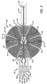
- FIG. 3 A layout for a zero-heat-flux, DTT measurement device is illustrated in FIG. 3 .
- the device includes an electrical circuit disposed on a flexible substrate in order to adapt or conform the physical configuration of the temperature measurement device to differing contours encountered at different temperature measurement locations.
- the flexible substrate is constructed or fabricated to have a plurality of contiguous sections.
- the flexible substrate 100 has three contiguous sections 102, 104, and 106.
- the first, or center, section 102 is substantially circular in shape.
- the second section (or "tail") 104 has the shape of a narrow, elongate rectangle that extends in a first radial direction from the periphery of the first section 102.
- the periphery of the center section has a straight portion and the width of the tail is reduced.
- the third, or tab, section 106 has the shape of a broad, elongate rectangle that extends in a second radial direction from the periphery of the center section 102.
- the tail and tab are aligned along a diameter of the center section.
- the elements of the electronic circuit are disposed on a single surface, on a first side 108 of the flexible substrate.
- a first thermal sensor 120 is positioned inside the outer perimeter of the center section 102, preferably near or at the center of the center section 102.
- An electrically conductive heater trace 122 defines a heater with a shape that surrounds or encircles a zone 121 in which the first thermal sensor 120 is located.
- the heater trace has an annular shape that includes a circular array of wedge-shaped heater zones 124 that surround or encircle the zone 121 and the first thermal sensor 120 which is disposed in the zone.
- a second thermal sensor 126 is positioned on the tail 104.
- a plurality of electrical connection pads 130 is located on the tab 106.
- the heater trace includes two electrically conductive trace sections that terminate in the connection pads 130a and 130b. Two electrically conductive traces extend between mounting pads on which the first thermal sensor 120 is mounted and the connection pads 130c and 130d. Two additional electrically conductive traces extend between mounting pads on which the second thermal sensor 126 is mounted and the connection pads 130e and 130f.
- the path of the heater trace 122 crosses the paths of the two traces for the second thermal sensor 126.
- the continuity of the heater trace is preferably, but not necessarily, maintained by an electrically conductive zero-ohm jumper 132 which crosses, and is electrically isolated from, the two traces for the second thermal sensor 126.
- the continuity of the heater trace 122 can also be maintained by vias to the second side of the flexible substrate, by running the thermal sensor traces around the periphery of the first side of the flexible substrate, by a jumper wire instead of the zero-ohm resistor, or by any equivalent solution.
- the flexibility or conformability of the flexible substrate can be enhanced by a plurality of slits 133 that define zones which move or flex independently of each other.
- the slits 133 are made in the center section 102 in a pattern that follows or accommodates the layout of the heater trace 122.
- the pattern at least partially separates the heater zones 124 so as to allow any one of the heater zones 124 to move independently of any other heater zone.
- the preferred pattern of slits is a radial pattern in that each slit is made along a respective radius of the circular center section 102, between adjacent heater zones, and extends along the radius from the periphery of the center section 102 toward the center of the circular shape of the section. This is not meant to exclude other possible slit configurations determined by the different shapes of the heater trace layout and the flexible substrate sections.
- Sections of the flexible substrate are brought or folded together about an insulator to provide thermal resistance between the first and second thermal sensors 120 and 126 in a configuration that is preferred for ZHF temperature measurement.
- at least the center and tail sections 102 and 104 of the flexible substrate are brought or folded together about a flexible insulator.
- the first and second thermal sensors 120 and 126 are thereby disposed on respective sides of a thermal insulator.
- the center section 102 and tail 104 are folded together about a flexible layer of insulating material 140.
- the layer 140 provides thermal and electrical resistance between the thermal sensors; it also supports the thermal sensors in a spaced-apart configuration.
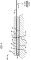
- a flexible temperature measurement device construction includes an electrical circuit laid out on a side of a flexible substrate as shown in FIG. 3 . With two sections of the flexible substrate brought or folded together so as to sandwich a flexible insulator, the construction has a multilayer structure as best seen in FIG. 4 .
- a temperature measurement device 200 includes the electrical circuit laid out on the surface of the first side 108 of the flexible substrate 100.
- the central and tail sections 102 and 104 are brought or folded together about the flexible insulating layer 140 so as to provide a thermal resistance between the first and second thermal sensors 120 and 126.
- the flexible insulating layer also maintains the first and second thermal sensors disposed in a spaced relationship.
- the second thermal sensor 126 is aligned with the first thermal sensor on a line 202 which passes through the zone 121 that is surrounded by the heater trace (seen in FIG. 3 ).
- the temperature measurement device further includes a flexible heater insulator 208 attached to a second side 109 of the substrate 100, over the center section 102.
- the layout of the electrical circuit illustrated in FIG. 3 locates all of the circuit components on a single surface on one side of the flexible substrate 100. This layout confers several advantages. First, it requires only a single fabrication sequence to lay down traces for the heater, the thermal sensors, and the connection pads, thereby simplifying manufacture of the device. Second, when the sections carrying the thermal sensors are folded together, the thermal sensors are maintained within a thermally and mechanically controlled environment.
- the first thermal sensor 120 is physically separated from the heater, in a zone 121 that is surrounded or encircled by the heater trace 122, and not stacked under it as in the Fox/Solman system.
- the heater is turned on and the heat produced thereby travels generally vertically from the heater to the patient, but only medially to the first thermal sensor.
- the jump in temperature that occurs when the heater is activated is not immediately sensed by the first thermal sensor, which improves control of the heater and stability of the temperature measurement without requiring an increase in thermal mass of the temperature measurement device.
- the first temperature sensor 120 is preferably located in the same plane, or on the same surface, as the heater trace 122 (and can even be elevated slightly above the heater trace), and substantially in or in alignment with the zone 121 of zero heat flux.
- the temperature measurement device support a pluggable interface for convenience and for modularity of a patient vital signs monitoring system.
- the tab 106 is configured with the array of pads 130 so as to be able to slide into and out of connection with a connector (not shown).
- the tab 106 is optionally stiffened.
- a flexible stiffener 204 is disposed on the second side 109 of the flexible substrate 100. The stiffener extends substantially coextensively with the tab 106 and at least partially over the center section 102. As best seen in FIG.
- the stiffener 204 is disposed between the second side 109 of the flexible substrate 100 and the flexible insulator 208.
- a key to align the tab 106 and prevent misconnection with an electrical connector (not shown) and to retain the connector on the tab may be provided on the device 200.
- such a key includes an opening 209 through the stiffener and tab. In operation, the opening 209 would receive and retain a retractable, spring-loaded pawl on the casing of a connector.
- the temperature measurement device 200 is mounted on a region of skin where temperature is to be measured with the second thermal sensor 126 closest to the skin.
- a layer of adhesive 222 is disposed on the second side 109, on the layer of insulation 140 and the portion of the tail 104 where the second sensor 126 is located.
- a release liner (not shown in this figure) may be peeled from the layer of adhesive 222 to prepare the device 200 for attachment to the skin.
- a pluggable signal interface between the electrical circuit on the device 200 and a temperature measurement system is provided through the plurality of electrical connection pads 130 located in the tab 106.
- the signals transferred therethrough would include at least heater activation and thermal sensor signals.
- the traces and pads for an electrical circuit are fabricated on a first side 108 of a flexible substrate 100 with a center section 102, a tail 104 extending from the center section, and a tab 106 extending from the center section.
- the electronic elements (first and second thermal sensors) are mounted to the traces to complete an electrical circuit (which is omitted from these figures for convenience) including the elements of FIG. 3 , laid out as shown in that figure. If used, the pattern of slits 133 separating the heater zones may be made in the center section in this manufacturing step.
- a stiffener 204 is laminated to a second side of the flexible substrate.
- the stiffener has a portion shaped identically to the tab and narrows to an elongated portion with a circular tip.
- the stiffener substantially extends over the tab and partially over the center section, beneath the zone 121 where the first thermal sensor is located.
- an adhesive film (not seen), or equivalent, attaches the stiffener to the second side of the flexible substrate.
- a flexible layer 208 of insulating material is attached by adhesive or equivalent to the first side of the flexible substrate, over substantially all of the center section and at least a portion of the stiffener.
- This layer is provided to insulate the heater from the ambient environment.
- this flexible layer may include a truncated tab 210 that provides additional reinforcement to a pluggable connection between the tab 106 and a system connector.
- a flexible central layer of insulating material 140 is attached to the first side 108, over the center section, to cover the heater trace and the first thermal sensor.
- this flexible layer may also include a truncated tab 141 that provides additional reinforcement to a pluggable connection between the tab and a system connector.
- the tail 104 is folded over the central layer of insulating material 140 such that the first and second thermal sensors are maintained by the central layer in the preferred spaced relationship.
- a layer of adhesive (not seen) with a release liner 226 is attached to the central insulating layer, over the central insulating layer with the tail folded thereto.
- the release liner 226 may have a shape that corresponds to the central section 102 and tab 106.
- a temperature measurement device has been fabricated using the materials and parts listed in the following table.
- An electrical circuit with copper traces and pads conforming to FIG. 3 was formed on a flexible substrate of polyimide film by a conventional photo-etching technique and thermal sensors were mounted using a conventional surface mount technique.
- the dimensions in the table are thicknesses, except that ⁇ signifies diameter.
- traces may be made wholly or partly with electrically conductive ink.
- Zero-heat-flux DTT measurement devices according to FIG. 3 and the preceding description have been fabricated, assembled, and clinically tested. We have found that it is desirable to further adapt the construction of such devices by provision of thermal sensor calibration circuitry that enables reliable estimation of deep tissue temperature measurement by zero-heat-flux operation. Desirably, the placement of the thermal sensor calibration circuitry on the measurement devices and provision of a pluggable connector interface at the periphery of the measurement device eliminate the need for a cable permanently fixed to the measurement device.
- a flexible substrate that supports an electrical circuit in which a heater trace is disposed on a first substrate layer to define a heater facing one side of a layer of thermally insulating material and surrounding a zone of the first substrate layer, a first thermal sensor is disposed in the zone, a thermal sensor calibration circuit is disposed on the first substrate layer outside of the heater, a second thermal sensor is disposed on the second substrate layer, a plurality of electrical pads is disposed outside of the heater trace on a substrate surface, and a plurality of conductive traces connects the heater trace, the first and second thermal sensors and the thermal sensor calibration circuit with the plurality of electrical pads.
- a heater trace is disposed on a first substrate layer to define a heater facing one side of a layer of thermally insulating material and surrounding a zone of the first substrate layer, a first thermal sensor is disposed in the zone, a second thermal sensor is disposed on the second substrate layer, and a plurality of electrical contact pads is disposed outside of the heater trace on a substrate surface to provide an interface where a connector can be detachably coupled to the measurement device.
- a memory device storing thermal sensor calibration information is disposed on the first substrate layer, and a plurality of conductive traces connects the heater trace, the first and second thermal sensors and the memory device with the plurality of electrical pads.
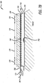
- FIG. 7A is a sectional, partially-schematic illustration of a preferred zero-heat-flux DTT measurement device construction.
- FIG. 7B is a sectional, partially-schematic illustration of the preferred zero-heat-flux DTT measurement device construction in which the section is rotated from the view of FIG. 7A .
- the measurement device 700 includes flexible substrate layers, a layer of thermally insulating material, and an electrical circuit.
- the electrical circuit includes a heater 726, a first thermal sensor 740, and a second thermal sensor 742.
- the heater 726 and the first thermal sensor 740 are disposed in or on a flexible substrate layer 703, and the second thermal sensor 742 is disposed in or on a flexible substrate layer 704.
- the first and second substrate layers 703 and 704 are separated by a flexible layer 702 of thermally insulating material.
- the flexible substrate layers 703 and 704 can be separate elements, but it is preferred that they be sections of a single flexible substrate folded around the layer of insulating material.
- adhesive film (not shown) attaches the substrate to the insulating layer 702.
- a layer of adhesive material 705 mounted to one side of the substrate layer 704 is provided with a removable liner (not shown) to attach the measurement device to skin.
- a flexible layer 709 of insulating material lies over the layers 702, 703, and 704 and is attached by adhesive film (not shown) to one side of the substrate layer 702.
- the insulating layer 709 extends over the heater 726 and the first thermal sensor 740.
- the electrical circuit further includes a thermal sensor calibration circuit 770 and electrical pads 771 disposed in or on the flexible substrate layer 703.
- the thermal sensor calibration circuit 770 is positioned outside of the heater 726, preferably between the heater 726 and the electrical pads 771.
- the electrical pads 771 are positioned on a section 708 of the substrate layer 703 that projects beyond the insulating layer 709 so as to be detachably coupled with a connector 772 fixed to the end of a cable 787.
- the thermal calibration circuit 770 includes a programmable memory storing thermal sensor calibration and other information.
- the thermal sensor calibration information can include one or more unique calibration coefficients for each thermistor.
- Location of the thermal sensor circuit on the measurement device 700, between the heater 726 and the electrical pads 771 permanently associates the stored thermal sensor calibration information with the measurement device 700.
- the need for a cable, with connector, permanently attached to the measurement device is eliminated.
- the cable 787 and connector 772 do not store unique calibration information, they can be used for any zero-heat-flux DTT measurement device configured in accordance with FIGS. 7A and 7B .
- location of the thermal sensor circuit 770, with stored thermal sensor calibration information, on the measurement device 700 enables use of low cost thermal sensors.
- the measurement device 700 is disposed with the second thermal sensor 742 nearest the skin.
- the layer 702 is sandwiched between the first and second substrate layers 703 and 704 so as to separate the heater 726 and first thermal sensor 740 from the second thermal sensor 742.
- the layer 702 acts as a large thermal resistance between the first and second thermal sensors, the second thermal sensor 742 senses the temperature of the skin, and the first thermal sensor senses the temperature of the layer 702. While the temperature sensed by the first thermal sensor 740 is less than the temperature sensed by the second thermal sensor 742, the heater is operated to reduce heat flow through the layer 702 and the skin.
- the heater 726 can include a central heater portion 728 that operates with a first power density, and a peripheral heater portion 729 surrounding the central heater portion that operates with a second power density higher than the first power density.
- the flexibility of the substrate permits the measurement device 700, including the heater 726, to conform to body contours where measurement is made.
- a first construction of a zero-heat-flux DTT measurement device 700 with thermal sensor calibration includes a flexible substrate 701.
- the flexible substrate 701 has contiguous sections 705, 706, and 708.
- the first, or center, section 705 is substantially circular in shape.
- the second section (or “tail”) 706 has the shape of a narrow, elongated rectangle with a bulbous end 707 that extends outwardly from the periphery of the center section 705 in a first direction.
- the third section (or "tab") is the extended section 708 seen in FIG. 7B .
- the tab 708 has the shape of a wide rectangle that extends outwardly from the periphery of the center section 705 in a second direction.
- Opposing notches 710 are formed in the tab 708 to receive and retain respective spring-loaded retainers of a connector (such as the connector 772 seen in FIG. 7B ).
- the tail 706 is displaced from the tab 708 by an arcuate distance of less than 180° in either a clockwise or a counterclockwise direction.
- an electrical circuit 720 is disposed on the flexible substrate 701.
- the elements of the electrical circuit 720 are located on the surface 721 of the flexible substrate 701.
- the electrical circuit 720 includes at least an electrically conductive heater trace, thermal sensors, a thermal sensor calibration circuit, electrically conductive connective trace portions, and electrical connection pads.
- the heater trace 724 defines a generally annular heater 726 surrounding a zone 730 of the substrate 701 into which no portion of the heater trace 724 extends; in this regard, the zone 730 is not directly heated when the heater operates.
- the zone 730 occupies a generally circular portion of the surface 721. More completely, the zone 730 is a cylindrical section of the substrate 701 which includes the portion of the surface 721 seen in FIG.
- the zone 730 is centered in the center section 705 and is concentric with the heater 726.
- the first thermal sensor 740 is mounted on mounting pads formed in the zone 730.
- the second thermal sensor 742 is mounted on mounting pads disposed outside of the generally annular heater 726; preferably, these mounting pads are formed generally near the end of the tail 706, for example, in or near the center of the bulbous end 707 of the tail.
- the thermal sensor calibration circuit 770 includes at least one multi-pin electronic circuit device mounted on the measurement device 700.
- the thermal sensor calibration circuit 770 can be constituted of an electrically-erasable programmable read/write memory (EEPROM) mounted on mounting pads formed on a portion of the surface 721 on the center section 705 near or adjacent the tab 708.
- the electrical connection pads (“electrical pads") 771 are formed on the surface 721, in the tab 708.
- a plurality of conductive trace portions connects the first and second thermal sensors, the thermal sensor calibration circuit 770, and the heater trace 724 with a plurality of the electrical pads 771.
- at least one electrical pad 771 is shared by the thermal sensor calibration circuit 770 and one of the heater 726, the first thermal sensor 740, and the second thermal sensor 742.
- the center section 705 has formed therein a plurality of slits 751, 752 to enhance the flexibility and conformability of the flexible substrate.
- the slits extend radially from the periphery toward the center of the center section 705.
- the slits define zones which move or flex independently of each other.
- the layout of the heater trace 724 is adapted to accommodate the slits.
- the heater trace follows a zigzag or switchback pattern with legs that increase in length from the periphery of the zone 730 to the ends of the longer slits 751 and then, after a step decrease at those ends, generally increase in length again to the outer periphery of the heater 726 in the zones defined by the slits.
- the construction of the heater has a generally annular shape centered in the zone 730, although the annularity is interrupted by the slits.
- the annular shape can be viewed as including a peripheral annulus of wedge-shaped heater zones surrounding a generally continuous central annulus.
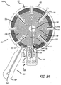
- the heater 726 has a non-uniform power density heater structure that can be understood with reference to FIG. 8A .
- the heater 726 includes a central portion 728 (indicated by lightly drawn lines) having a first power density and a peripheral portion 729 (indicated by heavily drawn lines) which surrounds the central portion 728 and has a second power density higher than the first power density.
- the heater trace 724 is continuous and includes two ends, a first of which transitions to electrical pad 5, and the second to electrical pad 6.
- each of the central and peripheral portions 728 and 729 includes a plurality of sections arranged in a sequence, in which the sections of the central portion 728 alternate with the sections of the peripheral portion.
- the annular structure of the heater arrays the sections of the central portion 728 generally in a central annulus around the zone 730, and arrays the sections of the peripheral portion 729 around the central portion 728.
- the central portion 728 produces a central annulus of heat at the first power density surrounding the zone 730 and the peripheral portion 729 produces a ring-shaped annulus of heat at the second power density that surrounds the central annulus of heat.
- the heater trace 724 is continuous, but exhibits a nonuniform power density along its length such that the central heater portion 728 has a first power density and the peripheral portion 729 has a second power density that is greater than the first power density.
- a driving voltage applied to the heater 726 will cause the central heater portion 728 to produce less power per unit of heater area of the heater trace than the outer heater portion 729.
- the result will be a central annulus of heat at a first average power surrounded by a ring of heat a second average power higher than the first.
- the differing power densities of the heater portions 728 and 729 may be invariant within each portion, or they may vary. Variation of power density may be step-wise or continuous. Power density is most simply and economically established by the width of the heater trace 724 and/or the pitch (distance) between the legs of a switchback pattern. For example, the resistance, and therefore the power generated by the heater trace, varies inversely with the width of the trace. For any resistance, the power generated by the heater trace also varies inversely with the pitch of (distance between) the switchback legs.
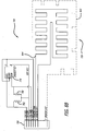
- the electrical circuit 720 on the flexible substrate 701 seen in FIG. 8A is shown in schematic form in FIG. 8B .
- the electrical pads 771 on the tab 708 numbered 1-6 in FIG. 8A correspond to the identically-numbered elements in FIG. 8B .
- the number of electrical pads shown is merely for illustration. More, or fewer, electrical pads can be used; any specific number is determined by design choices including the specific device configuration of the thermal sensor calibration circuit, the heater construction, the number of thermal sensors, and so on.
- the thermal sensor calibration circuit 770 includes a multi-pin electronically programmable memory (EEPROM) such as a 24AA01T-I/OT manufactured by Microchip Technology and mounted by mounting pads to the zero-heat-flux DTT measurement device 700.
- EEPROM electronically programmable memory
- FIGS. 8A and 8B illustrate a construction in which one or more electrical pads are shared by at least two elements of the electrical circuit. In this regard:
- the center section 705 and tail 706 are folded together about a flexible layer of insulating material such as the layer 702.
- the layer 702 provides thermal resistance and electrical insulation between the thermal sensors; it also supports the thermal sensors in a spaced-apart configuration.
- the first and second thermal sensors 740 and 742 are disposed on respective layers of substrate material that are separated by the layer of insulating material with the heater and first thermal sensor facing one side of the layer of insulating material and the second thermal sensor facing the other.
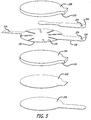
- the zero-heat-flux DTT measurement device 700 with the electrical circuit 720 laid out on one or more sides of the flexible substrate 701 as illustrated in FIG. 8A , can be manufactured and assembled in the manner illustrated in FIGS. 5 and 6A-6F , using materials identified in the Table of Materials and Parts II.
- the measurement device is constructed with a stiffener comprising a separate piece or a layer of material painted, deposited, or formed on the tab 708 and then hardened.
- the stiffener reduces the flexibility of the tab 708, thereby enabling it to be reliably coupled to and decoupled from a connector.
- such a stiffener for the tab 708 FIG.
- the stiffener extends substantially coextensively with the tab 708, and at least partially over the center section 705, but stops short of the zone 730, approximately where indicated by the dashed line 711 in FIG. 8A .
- FIG. 8A and the corresponding electrical circuit of FIG. 8B illustrate an interface by which operation of a zero-heat-flux DTT measurement device with a thermal sensor calibration circuit can be controlled and monitored in a DTT measurement system.
- FIG. 9 illustrates a signal interface between a zero-heat-flux DTT measurement device according to FIGS. 7A and 7B , using the first construction of FIG. 8A as an example.
- a DTT measurement system includes control mechanization 800, a measurement device 700, and an interface 785 that transfers power, common, and data signals between the control mechanization and the measurement device.
- the interface can be wireless, with transceivers located to send and receive signals.
- the interface includes a cable 787 with a connector 789 releasably connected to the tab 708.
- the control mechanization 800 manages the provision of power and common signals on respective signal paths to the heater and provides for the separation of the signals that share a common signal path, such as the Thermistor2 (TH2) and SCL signals.
- a common reference voltage signal is provided on a single signal path to the thermal sensors, and respective separate return signal paths provide sensor data from the thermal sensors.
- the thermal sensor calibration circuit 770 includes an EEPROM
- a separate signal path is provided for EEPROM ground, and the thermal sensor signal paths are shared with various pins of the EEPROM as per FIGS. 8A and 8B .
- This signal path configuration separates the digital ground for the EEPROM from the DC ground (common) for the heater, for good reason. Presume that the EEPROM and the heater share an electrical pad for ground.
- the cable 787 including its connector contacts has a certain amount of resistance. If the heater 726 is powered up, the current through it has to return to the control mechanization 800 through the ground (common) contact, which means there will be some voltage developed on the measurement device side of the contact equal to the resistance of that line multiplied by the current through the heater 726.
- That voltage could be as high as 2 or 3 volts depending on the integrity of the contacts. If concurrently the supply voltage goes low on the EEPROM or even one of the logic lines goes low below this aforementioned generated voltage, the EEPROM would be reversed biased which could damage the part. Separating the heater and EEPROM grounds eliminates all these possibilities for damage to the EEPROM. Accordingly, it is desirable to electrically isolate the heater altogether from the other elements of the electrical circuit.
- a first electrical pad (electrical pad 5, for example) of the plurality of electrical pads is connected only to a first terminal end of the heater trace, while a second electrical pad (electrical pad 6, for example) of the plurality of electrical pads is connected only to the second terminal end of the heater trace.
- the thermal sensors are NTC thermistors.
- the common signal on electrical pad 2 is held at a constant voltage level to provide Vcc for the EEPROM and a reference voltage for the thermistors.
- Control is switched via the thermistor/EEPROM switch circuit between reading the thermistors and clocking/reading/writing the EEPROM.
- the thermal sensors are NTC (negative temperature coefficient) thermistors
- the EEPROM has stored in it one or more calibration coefficients for each thermistor.
- the calibration coefficients are read from the EEPROM through the SDA port in response to a clock signal provided to the SCL port of the EEPROM.
- Table of Signals and Electrical Characteristics summarizes an exemplary construction of the interface 785.
- Table of Signals and Electrical Characteristics Element Signals and Electrical Characteristics Thermal sensors 740, 742 Common reference signal is 3.3 volts DC. Outputs are analog.
- Heater 726 Total resistance 6.5 to 7.0 ohms driven by a pulse width modulated waveform of 3.3 volts DC. The power density of the peripheral portion 729 is 30%-60% higher than that of the center portion 728.
- EEPROM 770 Mocron Technology 24AA01T-I/OT
- Ground is 0 volts.
- Vcc is 3.3 volts DC.
- SCL and SDA pins see a low impedance source switched in parallel with the thermistor outputs.
- a temperature measurement device has been fabricated using the materials and parts listed in the following table.
- An electrical circuit with copper traces and pads was formed on a flexible substrate of polyimide film by a conventional photo-etching technique and thermal sensors were mounted using a conventional surface mount technique.
- the dimensions in the table are thicknesses, except that ⁇ signifies diameter.
- the traces may be made wholly or partly with electrically conductive ink.
- the thermal sensors are preferably thermistors, but PN junctions, thermocouples, or resistance temperature detectors can also be used.
- Flexible insulating layers 702, 709 Closed cell polyethylene foam with skinned major surfaces coated with pressure sensitive adhesive (PSA) Insulator 702: ⁇ 40 x 3.0 mm thick Insulator 709: ⁇ 40 x 3.0 mm thick Stiffener 10 mil thick PET film Stiffener: 0.25mm thick EEPROM 770 Micron Technology 24AA01T-I/OT
- calibration coefficients for the thermistors are obtained and stored in the EEPROM.
- the basis of obtaining accurate temperature sensing from the negative temperature coefficient thermistors is through calibration.
- the resistance of each thermistor decreases in a generally logarithmic relationship as temperature increases.
- Two models exist which provide adequate precision to result in ⁇ 0.05° C temperature accuracy over a 70° C span [ Fraden, J., "A two-point calibration of negative temperature coefficient thermistors,” Rev Sci Instru 71(4):1901-1905 ].
- T b 0 + b 1 ln R + b 2 ln R 2 ⁇ 1 which relates resistance, R, to temperature, T, as a function of three constants, b 0 , b 1 , and b 3 .
- Calibration entails placing the DTT measurement device in three successively higher thermally controlled environments and recording the resistance at each condition. The constants may then be solved for using three simultaneous equations. The three resulting constants for each individual thermistor are then recorded on the EEPROM on the DTT measurement device.
- a simplified model by Fraden is of the form: ln R ⁇ R 0 + ⁇ 0 1 + ⁇ T ⁇ T 0 T where the terms, ⁇ 0 , ⁇ , R 0 , and T 0 are constants for a given sensor.
- gamma is a normalized slope of beta. This is a linear relationship and gamma may be approximated as a constant for a given thermistor type. Calibration using the model proposed by Fraden thus entails placing the DTT measurement device in only two successively higher-temperature-controlled environments and recording the resistance at each temperature. The R 0 and T 0 are one of those sets of measured values. The four constants noted above for each individual thermistor are then recorded on the EEPROM on the DTT measurement device.
- the heater 726 includes continuous central and peripheral portions 728 and 729 with different power densities.
- Six electrical pads having the same connections as shown in FIGS. 8A and 8B are provided on the tab 708.
- the heater trace includes three traces: a first trace 810 that defines the central heater portion 728, a second trace 811, surrounding the first trace 810, that defines the peripheral heater portion 729, and a third trace 812 connected to the first and second traces at a shared node 814.
- the third trace 812 serves as a common connection between the first and second traces.
- This heater construction is thus constituted of independently-controlled central and peripheral heater portions that share a common lead.
- the construction can be considered as a heater with two heater elements.
- the power densities of the central and peripheral portions can be uniform or nonuniform.
- the peripheral portion can be driven at a higher power level than the central portion so as to provide the desired higher power density.
- the second heater construction requires three separate pins (6, 7, and 5) for the first, second, and third traces.
- seven electrical pads are provided on the tab 708.
- the heaters of the second heater construction are entirely electrically isolated from the other elements of the electrical circuit.
- the heater trace 726 includes three terminal ends and a first electrical pad (electrical pad 5, for example) of the plurality of electrical pads is connected only to a first terminal end of the heater trace, a second electrical pad (electrical pad 6, for example) of the plurality of electrical pads is connected only to the second terminal end of the heater trace, and a third electrical pad (electrical pad 7, for example) of the plurality of electrical pads is connected only to the third terminal end of the heater trace.
- the flexible substrate be configured with a circular central section, nor is it necessary that the annular heater be generally circular.
- the central substrate sections have multilateral and oval (or elliptical) shapes, as do the heaters. All of the constructions previously described can be adapted to these shapes as required by design, operational, or manufacturing considerations.
Description
- The subject matter relates to a device for use in the estimation of deep tissue temperature (DTT) as an indication of the core body temperature of humans or animals. More particularly, the subject matter relates to constructions of zero-heat-flux DTT measurement devices with provision for thermal sensor calibration.
- Deep tissue temperature measurement is the measurement of the temperature of organs that occupy cavities of human and animal bodies (core body temperature). DTT measurement is desirable for many reasons. For example, maintenance of core body temperature in a normothermic range during the perioperative cycle has been shown to reduce the incidence of surgical site infection; and so it is beneficial to monitor a patient's body core temperature before, during, and after surgery. Of course noninvasive measurement is highly desirable, for the safety and the comfort of a patient, and for the convenience of the clinician. Thus, it is most advantageous to obtain a noninvasive DTT measurement by way of a device placed on the skin.
- Noninvasive measurement of DTT by means of a zero-heat-flux device was described by Fox and Solman in 1971 (Fox RH, Solman AJ. A new technique for monitoring the deep body temperature in man from the intact skin surface. J. Physiol. Jan 1971:212(2): pp 8-10). The Fox/Solman system, illustrated in
FIG. 1 , estimates core body temperature using atemperature measurement device 10 with a controlled heater of essentially planar construction that stops or blocks heat flow through a portion of the skin. Because the measurement depends on the absence of heat flux through the skin area where measurement takes place, the technique is referred to as a "zero heat flux" (ZHF) measurement. Togawa improved the Fox/Solman technique with a DTT measurement device structure that accounted for multidimensional heat flow in tissue. (Togawa T. Non-Invasive Deep Body Temperature Measurement. In: Rolfe P (ed) Non-Invasive Physiological Measurements. Vol. 1. 1979. Academic Press, London, pp. 261-277). The Togawa device, illustrated inFIG. 2 , encloses Fox and Solman's ZHF design in a thick aluminum housing with a cylindrical annulus construction that reduces or eliminates radial heat flow from the center to the periphery of the device. - The Fox/Solman and Togawa devices utilize heat flux normal to the body to control the operation of a heater that blocks heat flow from the skin through a thermal resistance in order to achieve a desired ZHF condition. This results in a construction that stacks the heater, thermal resistance, and thermal sensors of a ZHF temperature measurement device, which can result in a substantial vertical profile. The thermal mass added by Togawa's cover improves the stability of the Fox/Solman design and makes the measurement of deep tissue temperature more accurate. In this regard, since the goal is zero heat flux through the device, the more thermal resistance the better. However, the additional thermal resistance adds mass and size, and also increases the time required to reach a stable temperature.
- The size, mass, and cost of the Fox/Solman and Togawa devices do not promote disposability. Consequently, they must be sanitized after use, which exposes them to wear and tear and undetectable damage. The devices must also be stored for reuse. As a result, use of these devices raises the costs associated with zero-heat-flux DTT measurement and can pose a significant risk of cross contamination between patients. It is thus desirable to reduce the size and mass of a zero-heat-flux DTT measurement device, without compromising its performance, in order to promote disposability after a single use.
- An inexpensive, disposable, zero-heat-flux DTT measurement device is described and illustrated in
FIGS. 3 and4 . The device is constituted of a flexible substrate and an electrical circuit disposed on a surface of the flexible substrate. The electrical circuit includes an essentially planar heater which is defined by an electrically conductive copper trace and which surrounds an unheated zone of the surface, a first thermal sensor disposed in the zone, a second thermal sensor disposed outside of the heater trace, a plurality of electrical pads disposed outside of the heater trace, and a plurality of conductive traces connecting the first and second thermal sensors and the heater trace with the plurality of electrical pads. Sections of the flexible substrate are folded together to place the first and second thermal sensors in proximity to each other. A layer of insulation disposed between the sections separates the first and second thermal sensors. The device is oriented for operation so as to position the heater and the first thermal sensor on one side of the layer of insulation and the second thermal sensor on the other and in close proximity to an area of skin where a measurement is to be taken. As seen inFIG. 4 , the layout of the electrical circuit on a surface of the flexible substrate provides a low-profile, zero-heat-flux DTT measurement device that is essentially planar, even when the sections are folded together. - Design and manufacturing choices made with respect to a zero-heat-flux DTT measurement device can influence the operation of the device. One such design choice relates to the thermal sensors used in the detection of the zero-heat-flux condition. Given the importance of core body temperature, it is very desirable that the thermal sensors produce accurate temperature data in order to enable reliable detection of the zero-heat-flux condition and accurate estimation of core body temperature. The tradeoff is between accuracy and cost of the thermal sensor. A number of thermal sensor devices are candidates for use in zero-heat-flux DTT measurement. Such devices include PN junctions, thermocouples, resistive temperature devices, and thermistors, for example. Thermistors are a good choice for reasons of small size, handling convenience, ease of use, and reliability in the temperature range of interest. Their relatively low cost makes them desirable candidates for single-use, disposable temperature measurement devices.
- The magnitude of a thermistor's resistance changes in response to a change of the temperature of the thermistor. Thus, to determine the magnitude of the temperature, the thermistor's resistance is measured and converted to a temperature value using a known relationship. However, batch-to-batch manufacturing variances can yield a large range variance in thermistor resistance. For example, low-cost thermistors can exhibit a range of ± 5% in resistance values from device to device at a given temperature, which yields a range of ± 2.5° C in temperature. Such a large range in variance can compromise the accuracy and reliability of zero-heat-flux temperature measurement. Thus, while it is desirable to use such thermistors in order to limit the cost of parts and labor in manufacturing zero-heat-flux DTT measurement devices, it is important to reduce, if not remove, the effects of resistance variance on device operation.
- The range of thermistor resistance variance can be neutralized by calibration of thermistor resistance using known methods, such as the Steinhart-Hart equation, which require knowledge of coefficients derived from values of thermistor resistance measured at fixed temperatures. When a thermistor is operated, the coefficients are used in known formulas to correct or adjust the magnitude of its indicated resistance. Such correction is called calibration.
- Preferably, once determined, the coefficients are stored in a memory device so as to be available for use when the thermistor is operated. For example, as described in
Japanese patent publication 2002-202205 - The cable of the deep temperature measuring device with its permanent connector results in a complex construction that is costly to manufacture, difficult to store, and awkward to handle. A full complement of probes for a temperature measuring system has as many cables as probes. The probes are reusable, and so the problems described above in connection with the Fox/Solman and Togawa devices are compounded by the presence of the cables.
-
US 6 827 487 B2 - An object of an invention completed in respect of the problems described above is to provide a zero-heat-flux DTT measurement device constituted of a flexible substrate and a zero-heat-flux electrical circuit disposed on a surface of the flexible substrate with thermal sensor calibration coefficients provided from a circuit mounted on the substrate.
- Another object of an invention completed in respect of the problems described above is to eliminate a cable and connector as integral parts of a zero-heat-flux DTT probe without sacrificing the cost-saving benefits of inexpensive thermal sensors.
- Another object of an invention completed in respect of the problems described above is to provide thermal sensor calibration for a zero-heat-flux DTT measurement device constituted of a flexible substrate and electrically conductive traces on a surface of the substrate for a heater and at least two thermal sensors.
- These and other objects are achieved with a zero-heat-flux DTT measurement device according to
claim 1 constituted of a flexible substrate supporting an electrical circuit including a heater trace defining a heater, thermal sensors, and a thermal sensor calibration circuit. - Preferably, the thermal sensor calibration circuit includes a programmable memory storing thermal measurement information including thermal sensor calibration coefficients.
-
-
FIG.1 is a schematic block diagram of a first prior art deep tissue temperature measurement system including a ZHF DTT measurement device. -
FIG. 2 is a schematic side sectional diagram of a second prior art deep tissue temperature measurement system including a ZHF deep tissue temperature measurement device with an aluminum cap. -
FIG. 3 is a plan view of a side of a flexible substrate showing an electrical circuit disposed on a surface of the substrate for temperature measurement. -
FIG. 4 is a side sectional view of a temperature device that incorporates the electrical circuit ofFIG. 3 . -
FIG. 5 is an exploded assembly view, in perspective, showing elements of the temperature device ofFIG. 4 . -
FIGS. 6A-6F illustrate a method of temperature device manufacture based on the temperature device ofFIGS. 4 and5 . -
FIG. 7A is a first side sectional, partly schematic illustration of a zero-heat-flux DTT measurement device illustrating components of a multi-layer construction. -
FIG. 7B is a second side sectional, partly schematic illustration of the zero-heat-flux DTT measurement device ofFIG. 7A rotated to illustrate a thermal sensor calibration circuit included in the multi-layer construction. -
FIG. 8A illustrates a first construction of the zero-heat-flux DTT measurement device construction ofFIG. 7 , andFIG. 8B is a schematic diagram including elements of the measurement device. -
FIG. 9 is a block diagram illustrating a temperature measurement system. -
FIG. 10 illustrates a second construction of the zero-heat-flux DTT measurement device construction ofFIG. 7 . -
FIG. 11 illustrates a third construction of the zero-heat-flux DTT measurement device construction ofFIG. 7 . -
FIG. 12 illustrates a fourth construction of the zero-heat-flux DTT measurement device construction ofFIG. 7 . -
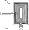
FIG. 13 illustrates a fifth construction of the zero-heat-flux DTT measurement device construction ofFIG. 7 . -
FIG. 14 illustrates a sixth construction of the zero-heat-flux DTT measurement device construction ofFIG. 7 . - It is desirable that zero heat flux, deep tissue temperature measurement device constructions include on-board thermal sensor calibration information in order to remove the effects of thermal sensor variance on device operation.
- A temperature device for zero-heat-flux DTT measurement includes a flexible substrate with at least two thermal sensors disposed in a spaced-apart relationship and separated by one or more flexible layers of thermally insulating material. Preferably the sensors are maintained in a spaced apart relationship by a flexible thermal (and electrical) insulator. The substrate supports at least the thermal sensors, the separating thermal insulator, a thermal sensor calibration circuit, and a heater.
- Although temperature device constructions are described in terms of preferred embodiments comprising representative elements, the embodiments are merely illustrative. It is possible that other embodiments will include more elements, or fewer, than described. It is also possible that some of the described elements will be deleted, and/or other elements that are not described will be added. Further, elements may be combined with other elements, and/or partitioned into additional elements.
- A layout for a zero-heat-flux, DTT measurement device is illustrated in
FIG. 3 . The device includes an electrical circuit disposed on a flexible substrate in order to adapt or conform the physical configuration of the temperature measurement device to differing contours encountered at different temperature measurement locations. Preferably, but not necessarily, the flexible substrate is constructed or fabricated to have a plurality of contiguous sections. For example, theflexible substrate 100 has threecontiguous sections section 102 is substantially circular in shape. The second section (or "tail") 104 has the shape of a narrow, elongate rectangle that extends in a first radial direction from the periphery of thefirst section 102. Where the center section and the tail join at 105, the periphery of the center section has a straight portion and the width of the tail is reduced. The third, or tab,section 106 has the shape of a broad, elongate rectangle that extends in a second radial direction from the periphery of thecenter section 102. Preferably, the tail and tab are aligned along a diameter of the center section. - As per
FIG. 3 , the elements of the electronic circuit are disposed on a single surface, on afirst side 108 of the flexible substrate. A firstthermal sensor 120 is positioned inside the outer perimeter of thecenter section 102, preferably near or at the center of thecenter section 102. An electricallyconductive heater trace 122 defines a heater with a shape that surrounds or encircles azone 121 in which the firstthermal sensor 120 is located. In the preferred embodiment illustrated inFIG. 3 , the heater trace has an annular shape that includes a circular array of wedge-shapedheater zones 124 that surround or encircle thezone 121 and the firstthermal sensor 120 which is disposed in the zone. A secondthermal sensor 126 is positioned on thetail 104. A plurality ofelectrical connection pads 130 is located on thetab 106. The heater trace includes two electrically conductive trace sections that terminate in theconnection pads thermal sensor 120 is mounted and theconnection pads thermal sensor 126 is mounted and theconnection pads - In the specific layout shown of the preferred embodiment shown in
FIG. 3 , the path of theheater trace 122 crosses the paths of the two traces for the secondthermal sensor 126. In this case, the continuity of the heater trace is preferably, but not necessarily, maintained by an electrically conductive zero-ohm jumper 132 which crosses, and is electrically isolated from, the two traces for the secondthermal sensor 126. In other embodiments, the continuity of theheater trace 122 can also be maintained by vias to the second side of the flexible substrate, by running the thermal sensor traces around the periphery of the first side of the flexible substrate, by a jumper wire instead of the zero-ohm resistor, or by any equivalent solution. - The flexibility or conformability of the flexible substrate can be enhanced by a plurality of
slits 133 that define zones which move or flex independently of each other. In the preferred embodiment, theslits 133 are made in thecenter section 102 in a pattern that follows or accommodates the layout of theheater trace 122. The pattern at least partially separates theheater zones 124 so as to allow any one of theheater zones 124 to move independently of any other heater zone. The preferred pattern of slits is a radial pattern in that each slit is made along a respective radius of thecircular center section 102, between adjacent heater zones, and extends along the radius from the periphery of thecenter section 102 toward the center of the circular shape of the section. This is not meant to exclude other possible slit configurations determined by the different shapes of the heater trace layout and the flexible substrate sections. - Sections of the flexible substrate are brought or folded together about an insulator to provide thermal resistance between the first and second
thermal sensors tail sections thermal sensors FIGS. 3 and4 , thecenter section 102 andtail 104 are folded together about a flexible layer of insulatingmaterial 140. Thelayer 140 provides thermal and electrical resistance between the thermal sensors; it also supports the thermal sensors in a spaced-apart configuration. - A flexible temperature measurement device construction includes an electrical circuit laid out on a side of a flexible substrate as shown in
FIG. 3 . With two sections of the flexible substrate brought or folded together so as to sandwich a flexible insulator, the construction has a multilayer structure as best seen inFIG. 4 . Thus, atemperature measurement device 200 includes the electrical circuit laid out on the surface of thefirst side 108 of theflexible substrate 100. The central andtail sections layer 140 so as to provide a thermal resistance between the first and secondthermal sensors thermal sensor 126 is aligned with the first thermal sensor on aline 202 which passes through thezone 121 that is surrounded by the heater trace (seen inFIG. 3 ). The temperature measurement device further includes aflexible heater insulator 208 attached to asecond side 109 of thesubstrate 100, over thecenter section 102. - The layout of the electrical circuit illustrated in
FIG. 3 locates all of the circuit components on a single surface on one side of theflexible substrate 100. This layout confers several advantages. First, it requires only a single fabrication sequence to lay down traces for the heater, the thermal sensors, and the connection pads, thereby simplifying manufacture of the device. Second, when the sections carrying the thermal sensors are folded together, the thermal sensors are maintained within a thermally and mechanically controlled environment. - Another benefit of the preferred layout shown in
FIG. 3 is that the firstthermal sensor 120 is physically separated from the heater, in azone 121 that is surrounded or encircled by theheater trace 122, and not stacked under it as in the Fox/Solman system. When the temperature measurement device is activated, the heater is turned on and the heat produced thereby travels generally vertically from the heater to the patient, but only medially to the first thermal sensor. As a result, the jump in temperature that occurs when the heater is activated is not immediately sensed by the first thermal sensor, which improves control of the heater and stability of the temperature measurement without requiring an increase in thermal mass of the temperature measurement device. Thus, thefirst temperature sensor 120 is preferably located in the same plane, or on the same surface, as the heater trace 122 (and can even be elevated slightly above the heater trace), and substantially in or in alignment with thezone 121 of zero heat flux. - It is desirable that the temperature measurement device support a pluggable interface for convenience and for modularity of a patient vital signs monitoring system. In this regard, and with reference to
FIGS. 3 and4 , thetab 106 is configured with the array ofpads 130 so as to be able to slide into and out of connection with a connector (not shown). In order to provide a physically robust structure capable of maintaining its shape while being connected and disconnected, thetab 106 is optionally stiffened. In this regard, aflexible stiffener 204 is disposed on thesecond side 109 of theflexible substrate 100. The stiffener extends substantially coextensively with thetab 106 and at least partially over thecenter section 102. As best seen inFIG. 4 , thestiffener 204 is disposed between thesecond side 109 of theflexible substrate 100 and theflexible insulator 208. A key to align thetab 106 and prevent misconnection with an electrical connector (not shown) and to retain the connector on the tab may be provided on thedevice 200. For example, with reference toFIG. 5 , such a key includes anopening 209 through the stiffener and tab. In operation, theopening 209 would receive and retain a retractable, spring-loaded pawl on the casing of a connector. - The
temperature measurement device 200 is mounted on a region of skin where temperature is to be measured with the secondthermal sensor 126 closest to the skin. As seen inFIG. 4 , a layer ofadhesive 222 is disposed on thesecond side 109, on the layer ofinsulation 140 and the portion of thetail 104 where thesecond sensor 126 is located. A release liner (not shown in this figure) may be peeled from the layer of adhesive 222 to prepare thedevice 200 for attachment to the skin. When deployed as shown inFIG. 4 , a pluggable signal interface between the electrical circuit on thedevice 200 and a temperature measurement system is provided through the plurality ofelectrical connection pads 130 located in thetab 106. The signals transferred therethrough would include at least heater activation and thermal sensor signals. - Use of an electrical circuit on a flexible substrate greatly simplifies the construction of a disposable temperature device for estimating deep tissue temperature, and substantially reduces the time and cost of manufacturing such a device. In this regard, manufacture of a temperature measurement device incorporating an electrical circuit laid out on a side of the
flexible substrate 100 with the circuit elements illustrated inFIG. 3 may be understood with reference toFIGS. 5 and6A-6F . Although a manufacturing method is described in terms of specifically numbered steps, it is possible to vary the sequence of the steps while achieving the same result. For various reasons, some of the steps may include more operations, or fewer, than described. For the same or additional reasons, some of the described steps may be deleted, and/or other steps that are not described may be added. Further, steps may be combined with other steps, and/or partitioned into additional steps. - In
FIG. 6A , the traces and pads for an electrical circuit are fabricated on afirst side 108 of aflexible substrate 100 with acenter section 102, atail 104 extending from the center section, and atab 106 extending from the center section. The electronic elements (first and second thermal sensors) are mounted to the traces to complete an electrical circuit (which is omitted from these figures for convenience) including the elements ofFIG. 3 , laid out as shown in that figure. If used, the pattern ofslits 133 separating the heater zones may be made in the center section in this manufacturing step. - As per
FIG. 6B , in a second manufacturing step, astiffener 204 is laminated to a second side of the flexible substrate. As best seen inFIG. 5 , the stiffener has a portion shaped identically to the tab and narrows to an elongated portion with a circular tip. When laminated to thesecond side 109, the stiffener substantially extends over the tab and partially over the center section, beneath thezone 121 where the first thermal sensor is located. Preferably, an adhesive film (not seen), or equivalent, attaches the stiffener to the second side of the flexible substrate. - As per
FIG. 6C , in a third manufacturing step, aflexible layer 208 of insulating material is attached by adhesive or equivalent to the first side of the flexible substrate, over substantially all of the center section and at least a portion of the stiffener. This layer is provided to insulate the heater from the ambient environment. As best seen inFIG. 5 , this flexible layer may include atruncated tab 210 that provides additional reinforcement to a pluggable connection between thetab 106 and a system connector. - As per
FIG. 6D , in a fourth manufacturing step, a flexible central layer of insulatingmaterial 140 is attached to thefirst side 108, over the center section, to cover the heater trace and the first thermal sensor. As best seen inFIG. 5 , this flexible layer may also include atruncated tab 141 that provides additional reinforcement to a pluggable connection between the tab and a system connector. - As per
FIG. 6E , in a fifth manufacturing step, thetail 104 is folded over the central layer of insulatingmaterial 140 such that the first and second thermal sensors are maintained by the central layer in the preferred spaced relationship. - As per
FIG. 6F , in a sixth manufacturing step, a layer of adhesive (not seen) with arelease liner 226 is attached to the central insulating layer, over the central insulating layer with the tail folded thereto. As best seen inFIG. 5 , therelease liner 226 may have a shape that corresponds to thecentral section 102 andtab 106. - In a best mode of practice, a temperature measurement device according to this specification has been fabricated using the materials and parts listed in the following table. An electrical circuit with copper traces and pads conforming to
FIG. 3 was formed on a flexible substrate of polyimide film by a conventional photo-etching technique and thermal sensors were mounted using a conventional surface mount technique. The dimensions in the table are thicknesses, except that Ø signifies diameter. Of course, these materials and dimensions are only illustrative and in no way limit the scope of this specification. For example, traces may be made wholly or partly with electrically conductive ink.Table of Materials and Parts: I Element Material Representative dimensions Flexible substrate Kapton® polyimide film with deposited and photo-etched copper traces and pads Substrate 100: 0.05mm Thermal sensors NTC thermistors, Part # R603-103F-3435-C, Redfish Sensors Flexible insulating layers Closed cell polyethylene foam with skinned major surfaces coated with pressure sensitive adhesive (PSA) Insulator 208: Ø50 x 1.5mm Insulator 140: Ø50.x 3.0mm Stiffener Polyethylene terephthalate (PET) Stiffener 204: 0.25mm - Zero-heat-flux DTT measurement devices according to
FIG. 3 and the preceding description have been fabricated, assembled, and clinically tested. We have found that it is desirable to further adapt the construction of such devices by provision of thermal sensor calibration circuitry that enables reliable estimation of deep tissue temperature measurement by zero-heat-flux operation. Desirably, the placement of the thermal sensor calibration circuitry on the measurement devices and provision of a pluggable connector interface at the periphery of the measurement device eliminate the need for a cable permanently fixed to the measurement device. - These objectives are met by zero-heat-flux DTT measurement device constructions with a flexible substrate that supports an electrical circuit in which a heater trace is disposed on a first substrate layer to define a heater facing one side of a layer of thermally insulating material and surrounding a zone of the first substrate layer, a first thermal sensor is disposed in the zone, a thermal sensor calibration circuit is disposed on the first substrate layer outside of the heater, a second thermal sensor is disposed on the second substrate layer, a plurality of electrical pads is disposed outside of the heater trace on a substrate surface, and a plurality of conductive traces connects the heater trace, the first and second thermal sensors and the thermal sensor calibration circuit with the plurality of electrical pads.
- These objectives are also met by zero-heat-flux DTT measurement device constructions with a flexible substrate that supports an electrical circuit in which a heater trace is disposed on a first substrate layer to define a heater facing one side of a layer of thermally insulating material and surrounding a zone of the first substrate layer, a first thermal sensor is disposed in the zone, a second thermal sensor is disposed on the second substrate layer, and a plurality of electrical contact pads is disposed outside of the heater trace on a substrate surface to provide an interface where a connector can be detachably coupled to the measurement device. A memory device storing thermal sensor calibration information is disposed on the first substrate layer, and a plurality of conductive traces connects the heater trace, the first and second thermal sensors and the memory device with the plurality of electrical pads.
-
FIG. 7A is a sectional, partially-schematic illustration of a preferred zero-heat-flux DTT measurement device construction.FIG. 7B is a sectional, partially-schematic illustration of the preferred zero-heat-flux DTT measurement device construction in which the section is rotated from the view ofFIG. 7A . Not all elements of the measurement device are shown in these figures; however, the figures do show relationships between components of the construction that are relevant to zero-heat-flux measurement with thermal sensor calibration. As perFIG. 7A , themeasurement device 700 includes flexible substrate layers, a layer of thermally insulating material, and an electrical circuit. The electrical circuit includes aheater 726, a firstthermal sensor 740, and a secondthermal sensor 742. Theheater 726 and the firstthermal sensor 740 are disposed in or on aflexible substrate layer 703, and the secondthermal sensor 742 is disposed in or on aflexible substrate layer 704. The first and second substrate layers 703 and 704 are separated by aflexible layer 702 of thermally insulating material. Theflexible substrate layers layer 702. A layer ofadhesive material 705 mounted to one side of thesubstrate layer 704 is provided with a removable liner (not shown) to attach the measurement device to skin. Preferably, aflexible layer 709 of insulating material lies over thelayers substrate layer 702. The insulatinglayer 709 extends over theheater 726 and the firstthermal sensor 740. - As seen in
FIG. 7B , the electrical circuit further includes a thermalsensor calibration circuit 770 andelectrical pads 771 disposed in or on theflexible substrate layer 703. The thermalsensor calibration circuit 770 is positioned outside of theheater 726, preferably between theheater 726 and theelectrical pads 771. Theelectrical pads 771 are positioned on asection 708 of thesubstrate layer 703 that projects beyond the insulatinglayer 709 so as to be detachably coupled with aconnector 772 fixed to the end of acable 787. As will be explained in detail with reference to other figures, thethermal calibration circuit 770 includes a programmable memory storing thermal sensor calibration and other information. Presuming that thethermal sensors measurement device 700, between theheater 726 and theelectrical pads 771 permanently associates the stored thermal sensor calibration information with themeasurement device 700. Thus, the need for a cable, with connector, permanently attached to the measurement device is eliminated. Moreover, since thecable 787 andconnector 772 do not store unique calibration information, they can be used for any zero-heat-flux DTT measurement device configured in accordance withFIGS. 7A and7B . Finally, location of thethermal sensor circuit 770, with stored thermal sensor calibration information, on themeasurement device 700, enables use of low cost thermal sensors. - With reference to
FIGS. 7A and7B , themeasurement device 700 is disposed with the secondthermal sensor 742 nearest the skin. Thelayer 702 is sandwiched between the first and second substrate layers 703 and 704 so as to separate theheater 726 and firstthermal sensor 740 from the secondthermal sensor 742. In operation, thelayer 702 acts as a large thermal resistance between the first and second thermal sensors, the secondthermal sensor 742 senses the temperature of the skin, and the first thermal sensor senses the temperature of thelayer 702. While the temperature sensed by the firstthermal sensor 740 is less than the temperature sensed by the secondthermal sensor 742, the heater is operated to reduce heat flow through thelayer 702 and the skin. When the temperature of thelayer 702 equals that of thethermal sensor 742, heat flow through thelayer 702 stops and the heater is switched off. This is the zero-heat-flux condition as it is sensed by the first andsecond sensors heater 726 can include acentral heater portion 728 that operates with a first power density, and aperipheral heater portion 729 surrounding the central heater portion that operates with a second power density higher than the first power density. Of course, the flexibility of the substrate permits themeasurement device 700, including theheater 726, to conform to body contours where measurement is made. - With reference to
FIG. 8A , a first construction of a zero-heat-fluxDTT measurement device 700 with thermal sensor calibration includes aflexible substrate 701. Preferably, but not necessarily, theflexible substrate 701 hascontiguous sections section 705 is substantially circular in shape. The second section (or "tail") 706 has the shape of a narrow, elongated rectangle with abulbous end 707 that extends outwardly from the periphery of thecenter section 705 in a first direction. The third section (or "tab") is theextended section 708 seen inFIG. 7B . Thetab 708 has the shape of a wide rectangle that extends outwardly from the periphery of thecenter section 705 in a second direction. Opposingnotches 710 are formed in thetab 708 to receive and retain respective spring-loaded retainers of a connector (such as theconnector 772 seen inFIG. 7B ). Preferably but not necessarily, thetail 706 is displaced from thetab 708 by an arcuate distance of less than 180° in either a clockwise or a counterclockwise direction. - As per
FIG. 8A , anelectrical circuit 720 is disposed on theflexible substrate 701. Preferably, but not necessarily, the elements of theelectrical circuit 720 are located on thesurface 721 of theflexible substrate 701. Theelectrical circuit 720 includes at least an electrically conductive heater trace, thermal sensors, a thermal sensor calibration circuit, electrically conductive connective trace portions, and electrical connection pads. Theheater trace 724 defines a generallyannular heater 726 surrounding azone 730 of thesubstrate 701 into which no portion of theheater trace 724 extends; in this regard, thezone 730 is not directly heated when the heater operates. Thezone 730 occupies a generally circular portion of thesurface 721. More completely, thezone 730 is a cylindrical section of thesubstrate 701 which includes the portion of thesurface 721 seen inFIG. 8A , the counterpart portion of the opposing surface (not seen in this figure), and the solid portion therebetween. Preferably, but not necessarily, thezone 730 is centered in thecenter section 705 and is concentric with theheater 726. The firstthermal sensor 740 is mounted on mounting pads formed in thezone 730. The secondthermal sensor 742 is mounted on mounting pads disposed outside of the generallyannular heater 726; preferably, these mounting pads are formed generally near the end of thetail 706, for example, in or near the center of thebulbous end 707 of the tail. In some constructions the thermalsensor calibration circuit 770 includes at least one multi-pin electronic circuit device mounted on themeasurement device 700. For example the thermalsensor calibration circuit 770 can be constituted of an electrically-erasable programmable read/write memory (EEPROM) mounted on mounting pads formed on a portion of thesurface 721 on thecenter section 705 near or adjacent thetab 708. The electrical connection pads ("electrical pads") 771 are formed on thesurface 721, in thetab 708. A plurality of conductive trace portions connects the first and second thermal sensors, the thermalsensor calibration circuit 770, and theheater trace 724 with a plurality of theelectrical pads 771. Preferably, but not necessarily, at least oneelectrical pad 771 is shared by the thermalsensor calibration circuit 770 and one of theheater 726, the firstthermal sensor 740, and the secondthermal sensor 742. - As seen in
FIG. 8A , preferably, but not necessarily, thecenter section 705 has formed therein a plurality ofslits center section 705. The slits define zones which move or flex independently of each other. The layout of theheater trace 724 is adapted to accommodate the slits. In this regard, the heater trace follows a zigzag or switchback pattern with legs that increase in length from the periphery of thezone 730 to the ends of the longer slits 751 and then, after a step decrease at those ends, generally increase in length again to the outer periphery of theheater 726 in the zones defined by the slits. As illustrated, the construction of the heater has a generally annular shape centered in thezone 730, although the annularity is interrupted by the slits. Alternatively, the annular shape can be viewed as including a peripheral annulus of wedge-shaped heater zones surrounding a generally continuous central annulus. - Preferably, but not necessarily, the
heater 726 has a non-uniform power density heater structure that can be understood with reference toFIG. 8A . In this construction, theheater 726 includes a central portion 728 (indicated by lightly drawn lines) having a first power density and a peripheral portion 729 (indicated by heavily drawn lines) which surrounds thecentral portion 728 and has a second power density higher than the first power density. Theheater trace 724 is continuous and includes two ends, a first of which transitions toelectrical pad 5, and the second toelectrical pad 6. However, because of the slits, each of the central andperipheral portions central portion 728 alternate with the sections of the peripheral portion. Nevertheless, the annular structure of the heater arrays the sections of thecentral portion 728 generally in a central annulus around thezone 730, and arrays the sections of theperipheral portion 729 around the central portion 728.When theheater 726 is operated, thecentral portion 728 produces a central annulus of heat at the first power density surrounding thezone 730 and theperipheral portion 729 produces a ring-shaped annulus of heat at the second power density that surrounds the central annulus of heat. - Preferably the
heater trace 724 is continuous, but exhibits a nonuniform power density along its length such that thecentral heater portion 728 has a first power density and theperipheral portion 729 has a second power density that is greater than the first power density. With this configuration, a driving voltage applied to theheater 726 will cause thecentral heater portion 728 to produce less power per unit of heater area of the heater trace than theouter heater portion 729. The result will be a central annulus of heat at a first average power surrounded by a ring of heat a second average power higher than the first. - The differing power densities of the
heater portions heater trace 724 and/or the pitch (distance) between the legs of a switchback pattern. For example, the resistance, and therefore the power generated by the heater trace, varies inversely with the width of the trace. For any resistance, the power generated by the heater trace also varies inversely with the pitch of (distance between) the switchback legs. - The
electrical circuit 720 on theflexible substrate 701 seen inFIG. 8A is shown in schematic form inFIG. 8B . Theelectrical pads 771 on thetab 708 numbered 1-6 inFIG. 8A correspond to the identically-numbered elements inFIG. 8B . The number of electrical pads shown is merely for illustration. More, or fewer, electrical pads can be used; any specific number is determined by design choices including the specific device configuration of the thermal sensor calibration circuit, the heater construction, the number of thermal sensors, and so on. In some constructions it is desirable to utilize one or more of the electrical pads for electrical signal conduction to or from more than a single element of theelectrical circuit 720 in order to minimize the number of electrical pads, thereby simplifying the circuit layout, minimizing the size and mass of thetab 708, and reducing interface connector size. - Presume that the thermal
sensor calibration circuit 770 includes a multi-pin electronically programmable memory (EEPROM) such as a 24AA01T-I/OT manufactured by Microchip Technology and mounted by mounting pads to the zero-heat-fluxDTT measurement device 700.FIGS. 8A and8B illustrate a construction in which one or more electrical pads are shared by at least two elements of the electrical circuit. In this regard: - one lead of the second
thermal sensor 742 andpin 1 of the thermalsensor calibration circuit 770 are connected by conductive trace portions toelectrical pad 1; - leads of the first and second
thermal sensors pin 4 of the thermalsensor calibration circuit 770 are connected by conductive trace portions toelectrical pad 2; - one lead of the first
thermal sensor 740 andpin 3 of the thermalsensor calibration circuit 770 are connected by conductive trace portions toelectrical pad 3; -
pins sensor calibration circuit 770 are connected by a conductive trace portion toelectrical pad 4; - the return end of the
heater trace 724 is connected by a conductive trace portion toelectrical pad 5; and - the input end of the
heater trace 724 is connected by a conductive trace portion toelectrical pad 6. - With reference to
FIGS. 7A ,7B , and8A , when themeasurement device 700 is assembled, thecenter section 705 andtail 706 are folded together about a flexible layer of insulating material such as thelayer 702. Thelayer 702 provides thermal resistance and electrical insulation between the thermal sensors; it also supports the thermal sensors in a spaced-apart configuration. In other words, the first and secondthermal sensors - The zero-heat-flux
DTT measurement device 700, with theelectrical circuit 720 laid out on one or more sides of theflexible substrate 701 as illustrated inFIG. 8A , can be manufactured and assembled in the manner illustrated inFIGS. 5 and6A-6F , using materials identified in the Table of Materials and Parts II. Preferably, the measurement device is constructed with a stiffener comprising a separate piece or a layer of material painted, deposited, or formed on thetab 708 and then hardened. The stiffener reduces the flexibility of thetab 708, thereby enabling it to be reliably coupled to and decoupled from a connector. Preferably, with reference toFIGS. 4 and8A , such a stiffener for the tab 708 (FIG. 8A ) is disposed on the side of theflexible substrate 701 that corresponds to thesecond side 109 of the flexible substrate 100 (FIG. 4 ). The stiffener extends substantially coextensively with thetab 708, and at least partially over thecenter section 705, but stops short of thezone 730, approximately where indicated by the dashedline 711 inFIG. 8A . - The physical layout of
FIG. 8A and the corresponding electrical circuit ofFIG. 8B illustrate an interface by which operation of a zero-heat-flux DTT measurement device with a thermal sensor calibration circuit can be controlled and monitored in a DTT measurement system.FIG. 9 illustrates a signal interface between a zero-heat-flux DTT measurement device according toFIGS. 7A and7B , using the first construction ofFIG. 8A as an example. With reference to these figures, a DTT measurement system includescontrol mechanization 800, ameasurement device 700, and aninterface 785 that transfers power, common, and data signals between the control mechanization and the measurement device. The interface can be wireless, with transceivers located to send and receive signals. Preferably, the interface includes acable 787 with aconnector 789 releasably connected to thetab 708. Thecontrol mechanization 800 manages the provision of power and common signals on respective signal paths to the heater and provides for the separation of the signals that share a common signal path, such as the Thermistor2 (TH2) and SCL signals. A common reference voltage signal is provided on a single signal path to the thermal sensors, and respective separate return signal paths provide sensor data from the thermal sensors. - Presuming that the thermal
sensor calibration circuit 770 includes an EEPROM, a separate signal path is provided for EEPROM ground, and the thermal sensor signal paths are shared with various pins of the EEPROM as perFIGS. 8A and8B . This signal path configuration separates the digital ground for the EEPROM from the DC ground (common) for the heater, for good reason. Presume that the EEPROM and the heater share an electrical pad for ground. Thecable 787 including its connector contacts has a certain amount of resistance. If theheater 726 is powered up, the current through it has to return to thecontrol mechanization 800 through the ground (common) contact, which means there will be some voltage developed on the measurement device side of the contact equal to the resistance of that line multiplied by the current through theheater 726. That voltage could be as high as 2 or 3 volts depending on the integrity of the contacts. If concurrently the supply voltage goes low on the EEPROM or even one of the logic lines goes low below this aforementioned generated voltage, the EEPROM would be reversed biased which could damage the part. Separating the heater and EEPROM grounds eliminates all these possibilities for damage to the EEPROM. Accordingly, it is desirable to electrically isolate the heater altogether from the other elements of the electrical circuit. Thus, as perFIG. 9 , a first electrical pad (electrical pad 5, for example) of the plurality of electrical pads is connected only to a first terminal end of the heater trace, while a second electrical pad (electrical pad 6, for example) of the plurality of electrical pads is connected only to the second terminal end of the heater trace. - With reference to
FIG. 8B , presume that the thermal sensors are NTC thermistors. In this case, the common signal onelectrical pad 2 is held at a constant voltage level to provide Vcc for the EEPROM and a reference voltage for the thermistors. Control is switched via the thermistor/EEPROM switch circuit between reading the thermistors and clocking/reading/writing the EEPROM. Presuming again that the thermal sensors are NTC (negative temperature coefficient) thermistors, the EEPROM has stored in it one or more calibration coefficients for each thermistor. When thedevice 700 is connected to the control mechanization, the calibration coefficients are read from the EEPROM through the SDA port in response to a clock signal provided to the SCL port of the EEPROM. The following Table of Signals and Electrical Characteristics summarizes an exemplary construction of theinterface 785.Table of Signals and Electrical Characteristics Element Signals and Electrical Characteristics Thermal sensors Common reference signal is 3.3 volts DC. Outputs are analog. Heater 726Total resistance 6.5 to 7.0 ohms driven by a pulse width modulated waveform of 3.3 volts DC. The power density of the peripheral portion 729 is 30%-60% higher than that of thecenter portion 728.EEPROM 770 (Micron Technology 24AA01T-I/OT) Ground is 0 volts. Vcc is 3.3 volts DC. SCL and SDA pins see a low impedance source switched in parallel with the thermistor outputs. - In a best mode of practice, a temperature measurement device according to
FIG. 8A has been fabricated using the materials and parts listed in the following table. An electrical circuit with copper traces and pads was formed on a flexible substrate of polyimide film by a conventional photo-etching technique and thermal sensors were mounted using a conventional surface mount technique. The dimensions in the table are thicknesses, except that Ø signifies diameter. Of course, these materials and dimensions are only illustrative and in no way limit the scope of this specification. For example, the traces may be made wholly or partly with electrically conductive ink. In another example, the thermal sensors are preferably thermistors, but PN junctions, thermocouples, or resistance temperature detectors can also be used.Table of Materials and Parts: II Element Material/Part Representative dimensions/characteristics Flexible substrate 701,heater 726, contacts, andpads 2 mil thick Polyethylene terephthalate (PET) film with deposited and photo-etched ½ oz. copper traces and pads and immersion silver-plated contacts. Substrate 701: 0.05mm thick Thermal sensors Negative Temperature Coefficient (NTC) thermistors, Part # R603-103F-3435-C, Redfish Sensors. 10k thermistors in 0603 package. Flexible insulating layers Closed cell polyethylene foam with skinned major surfaces coated with pressure sensitive adhesive (PSA) Insulator 702: Ø40 x 3.0 mm thick Insulator 709: Ø40 x 3.0 mm thick Stiffener 10 mil thick PET film Stiffener: 0.25mm thick EEPROM 770 Micron Technology 24AA01T-I/OT - According to the best mode, calibration coefficients for the thermistors are obtained and stored in the EEPROM. The basis of obtaining accurate temperature sensing from the negative temperature coefficient thermistors is through calibration. The resistance of each thermistor decreases in a generally logarithmic relationship as temperature increases. Two models exist which provide adequate precision to result in ± 0.05° C temperature accuracy over a 70° C span [Fraden, J., "A two-point calibration of negative temperature coefficient thermistors," Rev Sci Instru 71(4):1901-1905]. The best known is the Steinhart and Hart model:

- A simplified model by Fraden, is of the form:


- The value of gamma is a normalized slope of beta. This is a linear relationship and gamma may be approximated as a constant for a given thermistor type. Calibration using the model proposed by Fraden thus entails placing the DTT measurement device in only two successively higher-temperature-controlled environments and recording the resistance at each temperature. The R0 and T0 are one of those sets of measured values. The four constants noted above for each individual thermistor are then recorded on the EEPROM on the DTT measurement device.
- In a second construction of the
measurement device 700, illustrated inFIG. 10 , no slits are provided in thesubstrate 701, and so theheater 726 includes continuous central andperipheral portions FIGS. 8A and8B are provided on thetab 708. - In third and fourth constructions of the
measurement device 700, illustrated inFIG. 11 and12 , respectively, the heater trace includes three traces: afirst trace 810 that defines thecentral heater portion 728, asecond trace 811, surrounding thefirst trace 810, that defines theperipheral heater portion 729, and athird trace 812 connected to the first and second traces at a sharednode 814. Thethird trace 812 serves as a common connection between the first and second traces. This heater construction is thus constituted of independently-controlled central and peripheral heater portions that share a common lead. Alternatively, the construction can be considered as a heater with two heater elements. The power densities of the central and peripheral portions can be uniform or nonuniform. If the power densities of the two portions are uniform, the peripheral portion can be driven at a higher power level than the central portion so as to provide the desired higher power density. As perFIGS. 8B ,9 ,11 , and12 the second heater construction requires three separate pins (6, 7, and 5) for the first, second, and third traces. Thus, for a construction of the electrical circuit that includes two independently-controlled heater portions that share a common lead, seven electrical pads are provided on thetab 708. As with the first heater construction, the heaters of the second heater construction are entirely electrically isolated from the other elements of the electrical circuit. In this regard, with reference toFIGS. 9 and11 , theheater trace 726 includes three terminal ends and a first electrical pad (electrical pad 5, for example) of the plurality of electrical pads is connected only to a first terminal end of the heater trace, a second electrical pad (electrical pad 6, for example) of the plurality of electrical pads is connected only to the second terminal end of the heater trace, and a third electrical pad (electrical pad 7, for example) of the plurality of electrical pads is connected only to the third terminal end of the heater trace. - It is not necessary that the flexible substrate be configured with a circular central section, nor is it necessary that the annular heater be generally circular. In ninth and tenth constructions of the
measurement device 700, illustrated inFIGS. 13 and14 , respectively, the central substrate sections have multilateral and oval (or elliptical) shapes, as do the heaters. All of the constructions previously described can be adapted to these shapes as required by design, operational, or manufacturing considerations. - Although principles of temperature measurement device construction and manufacture have been described with reference to presently preferred embodiments, it should be understood that various modifications can be made without departing from the scope of the invention, which is defined only by the following claims.
Claims (11)
- A zero-heat-flux temperature device (700) with first and second flexible substrate layers (703, 704) sandwiching a layer (702) of thermally insulating material, characterized by:a heater trace (724) disposed on the first substrate layer (703) that defines a heater (726) facing one side of the layer of thermally insulating material and surrounding a zone (730) of the first substrate layer having no heater trace;a first thermal sensor (740) disposed on the first substrate layer (703) in the zone (730);a thermal sensor calibration circuit (770) disposed on the first substrate layer (703) outside of the heater;a second thermal sensor (742) disposed on the second substrate layer (704);a plurality of electrical pads (771) disposed outside of the heater trace on a substrate surface (721) of the first flexible substrate layer (703); anda plurality of conductive traces connecting the heater trace, the first and second thermal sensors, and the thermal sensor calibration circuit with the plurality of electrical pads.
- The zero-heat-flux temperature device (700) of claim 1, in which a flexible substrate (701) includes a center section (705), a tab (706) extending outwardly from the periphery of the center section, and a tail (708) extending outwardly from the periphery of the center section, the plurality of electrical pads (771) is disposed on the tab, and the center section and the tail are folded around the layer (702) of thermal insulating material such that the center section (705) constitutes the first substrate layer (703) and the tail (708) constitutes the second substrate layer (704).
- The zero-heat-flux temperature device (700) of claim 2, in which the thermal sensor calibration circuit (770) is disposed on a surface portion of the substrate (701) extending partially over the tab and the center section.
- The zero-heat-flux temperature device (700) of claims 1-3, in which the thermal sensor calibration circuit (770) includes a programmable memory storing thermal sensor calibration information.
- The zero-heat-flux temperature device (700) of claim 2, in which the thermal sensor calibration circuit (770) is disposed between the heater (726) and the plurality of electrical pads (771).
- The zero-heat-flux temperature device (700) of claim 5, in which the plurality of electrical pads (771) includes at least six electrical pads ((1-6), (1-7)).
- The zero-heat-flux temperature device (700) of claims 1-6, in which the heater trace (724) includes two terminal ends and a first electrical pad (5) of the plurality of electrical pads (1-6) is connected only to a first terminal end of the heater trace and a second electrical pad (6) of the plurality of electrical pads is connected only to the second terminal end of the heater trace.
- The zero-heat-flux temperature device (700) of claim 1-6, in which the heater trace (724) includes three terminal ends and a first electrical pad (5) of the plurality of electrical pads (1-7) is connected only to a first terminal end of the heater trace, a second electrical pad (6) of the plurality of electrical pads is connected only to the second terminal end of the heater trace, and a third electrical pad (7) of the plurality of electrical pads is connected only to the third terminal end of the heater trace.
- The zero-heat-flux temperature device (700) of claim 1, in which the heater (726) includes a central heater portion (728) surrounding the zone (730) and a peripheral heater portion (729) surrounding the central heater portion.
- The zero-heat-flux temperature device (700) of claim 9, in which the central heater portion (728) is a first power density portion, the peripheral heater portion (729) is a second power density portion, and the second power density is greater than the first power density.
- The zero-heat-flux temperature device (700) of any one of claims 2-8, in which the center section has a circular shape, a quadrilateral shape, or an oval shape.
Applications Claiming Priority (2)
| Application Number | Priority Date | Filing Date | Title |
|---|---|---|---|
| US12/798,668 US8292495B2 (en) | 2010-04-07 | 2010-04-07 | Zero-heat-flux, deep tissue temperature measurement devices with thermal sensor calibration |
| PCT/US2011/000549 WO2011146098A1 (en) | 2010-04-07 | 2011-03-24 | Zero-heat-flux, deep tissue temperature measurement devices with thermal sensor calibration |
Publications (2)
| Publication Number | Publication Date |
|---|---|
| EP2556351A1 EP2556351A1 (en) | 2013-02-13 |
| EP2556351B1 true EP2556351B1 (en) | 2017-04-26 |
Family
ID=44070659
Family Applications (1)
| Application Number | Title | Priority Date | Filing Date |
|---|---|---|---|
| EP11713899.0A Active EP2556351B1 (en) | 2010-04-07 | 2011-03-24 | Zero-heat-flux, deep tissue temperature measurement device with thermal sensor calibration |
Country Status (5)
| Country | Link |
|---|---|
| US (2) | US8292495B2 (en) |
| EP (1) | EP2556351B1 (en) |
| JP (1) | JP5779806B2 (en) |
| CN (1) | CN102884406B (en) |
| WO (1) | WO2011146098A1 (en) |
Families Citing this family (37)
| Publication number | Priority date | Publication date | Assignee | Title |
|---|---|---|---|---|
| JP5181914B2 (en) * | 2008-08-08 | 2013-04-10 | ブラザー工業株式会社 | Positioning method |
| WO2010120362A1 (en) | 2009-04-15 | 2010-10-21 | Arizant Healthcare Inc. | Deep tissue temperature probe constructions |
| CN102458232A (en) * | 2009-04-15 | 2012-05-16 | 亚利桑特保健公司 | Deep tissue temperature probe constructions |
| US8226294B2 (en) * | 2009-08-31 | 2012-07-24 | Arizant Healthcare Inc. | Flexible deep tissue temperature measurement devices |
| JP5732737B2 (en) * | 2010-04-02 | 2015-06-10 | セイコーエプソン株式会社 | Temperature measuring apparatus and temperature measuring method |
| US8292495B2 (en) | 2010-04-07 | 2012-10-23 | Arizant Healthcare Inc. | Zero-heat-flux, deep tissue temperature measurement devices with thermal sensor calibration |
| US8292502B2 (en) | 2010-04-07 | 2012-10-23 | Arizant Healthcare Inc. | Constructions for zero-heat-flux, deep tissue temperature measurement devices |
| EP2676110A1 (en) * | 2011-02-16 | 2013-12-25 | Arizant Healthcare Inc. | Zero-heat-flux temperature measurement devices with peripheral skin temperature measurement |
| WO2012129129A2 (en) | 2011-03-18 | 2012-09-27 | Augustine Biomedical And Design Llc | Non-invasive core temperature sensor |
| US9354122B2 (en) | 2011-05-10 | 2016-05-31 | 3M Innovative Properties Company | Zero-heat-flux, deep tissue temperature measurement system |
| US9664574B2 (en) | 2013-07-30 | 2017-05-30 | Texas Instruments Incorporated | Thermometer device and method of making |
| WO2015092627A1 (en) * | 2013-12-18 | 2015-06-25 | Koninklijke Philips N.V. | Continuous temperature profiling and control during surgery |
| EP3149507B1 (en) * | 2014-04-15 | 2023-08-16 | Koninklijke Philips N.V. | Low cost magnetic resonance safe probe for temperature measurement |
| EP3146529B1 (en) * | 2014-05-19 | 2019-10-23 | Sun Chemical Corporation | A silver paste containing bismuth oxide and its use in solar cells |
| US9483726B2 (en) * | 2014-12-10 | 2016-11-01 | VivaLnk Inc. | Three dimensional electronic patch |
| JP2016164525A (en) * | 2015-03-06 | 2016-09-08 | セイコーエプソン株式会社 | Temperature measurement device and temperature measurement method |
| CN106137139B (en) * | 2015-04-03 | 2019-06-18 | 凯健企业股份有限公司 | The modular construction and its manufacturing method of the temperature sensing unit of clinical thermometer |
| KR101779837B1 (en) | 2015-04-22 | 2017-09-20 | 송국섭 | A device for the measurement of tympanic temperature with non-invasive and zero-heat flux technology |
| US9897492B2 (en) * | 2015-05-06 | 2018-02-20 | K-Jump Health Co., Ltd. | Method for manufacturing temperature measure units of thermometers |
| US10728956B2 (en) * | 2015-05-29 | 2020-07-28 | Watlow Electric Manufacturing Company | Resistive heater with temperature sensing power pins |
| US10750951B1 (en) * | 2016-02-25 | 2020-08-25 | Verily Life Sciences Llc | Core temperature measurement using asymmetric sensors |
| US10588778B2 (en) | 2016-03-21 | 2020-03-17 | Stryker Corporation | Mobile thermal system |
| EP3457922A1 (en) * | 2016-05-18 | 2019-03-27 | Koninklijke Philips N.V. | Single heat flux sensor arrangement |
| WO2018013552A1 (en) | 2016-07-12 | 2018-01-18 | Stryker Corporation | Thermal control system |
| US11259958B2 (en) | 2016-08-11 | 2022-03-01 | Stryker Corporation | Thermal therapy devices |
| US10856741B2 (en) * | 2016-12-14 | 2020-12-08 | Vital Connect, Inc. | Core body temperature detection device |
| US10820802B2 (en) * | 2016-12-30 | 2020-11-03 | Welch Allyn, Inc. | Wearable patch for patient monitoring |
| CN110402100A (en) | 2017-03-14 | 2019-11-01 | M·哈伯 | Mthods, systems and devices for non-invasive core body temperature monitoring |
| CA3058651A1 (en) | 2017-04-04 | 2018-10-11 | Allevi, Inc. | Multi-headed auto-calibrating bioprinter with heads that heat, cool, and crosslink |
| EP3788333A4 (en) * | 2018-05-02 | 2022-05-11 | 3M Innovative Properties Company | Core body temperature device and system |
| US11872156B2 (en) | 2018-08-22 | 2024-01-16 | Masimo Corporation | Core body temperature measurement |
| CN110035625B (en) * | 2019-03-07 | 2021-07-06 | 武汉迈斯卡德微电子科技有限公司 | Method for manufacturing signal measurement medium soft board |
| CN114008422A (en) | 2019-07-01 | 2022-02-01 | 保热感应公司 | Apparatus, system, and method for non-invasive thermal interrogation |
| US11635334B2 (en) * | 2020-06-30 | 2023-04-25 | Apple Inc. | Miniature external temperature sensing device for estimating subsurface tissue temperatures |
| US11408778B2 (en) | 2020-07-21 | 2022-08-09 | Apple Inc. | Temperature gradient sensing in portable electronic devices |
| US11771329B2 (en) | 2020-09-24 | 2023-10-03 | Apple Inc. | Flexible temperature sensing devices for body temperature sensing |
| WO2023228726A1 (en) * | 2022-05-27 | 2023-11-30 | Semitec株式会社 | Deep temperature measurement device and deep temperature measurement method |
Family Cites Families (156)
| Publication number | Priority date | Publication date | Assignee | Title |
|---|---|---|---|---|
| US1363259A (en) | 1919-09-19 | 1920-12-28 | Mills David Hirst | Thermometer-cover |
| US1526641A (en) | 1921-08-09 | 1925-02-17 | Pacific Fire Extinguisher Comp | Thermopile |
| US1638943A (en) | 1922-09-27 | 1927-08-16 | Westinghouse Electric & Mfg Co | Thermoelectric cell and method of making the same |
| US1528383A (en) | 1923-06-11 | 1925-03-03 | Schmidt Ernst | Device for the measurement of heat |
| US2378804A (en) | 1940-05-13 | 1945-06-19 | Honeywell Regulator Co | Thermocouple |
| US2381819A (en) | 1942-08-19 | 1945-08-07 | Alltools Ltd | Thermocouple |
| US2629757A (en) | 1943-11-08 | 1953-02-24 | Warren Dunham Foster | Method of construction of sensitive thermopiles |
| US2519785A (en) | 1944-08-14 | 1950-08-22 | Okolicsanyi Ferenc | Thermopile |
| US2807657A (en) | 1953-12-21 | 1957-09-24 | North American Aviation Inc | Method of making a thermopile |
| US2969141A (en) | 1957-06-17 | 1961-01-24 | Eugene M Katzin | Thermometer cover |
| US3099575A (en) | 1959-10-20 | 1963-07-30 | Engelhard Ind Inc | Thermocouple |
| US3099923A (en) | 1960-01-18 | 1963-08-06 | Theodor H Benzinger | Thermopile switching systems |
| US3238775A (en) | 1962-01-02 | 1966-03-08 | Lockheed Aircraft Corp | Heat flux responsive device |
| FI43701B (en) | 1962-02-14 | 1971-02-01 | H Jaerund | |
| SE303009B (en) | 1962-12-07 | 1968-08-12 | Berger J Welin | |
| US3427209A (en) | 1965-05-18 | 1969-02-11 | Armstrong Cork Co | Quick response heat-sensing element |
| US3367182A (en) | 1965-06-02 | 1968-02-06 | Nasa Usa | Heat flux measuring system |
| US3301394A (en) | 1965-10-15 | 1967-01-31 | Medical Supply Company | Sheath package |
| US3581570A (en) | 1967-09-05 | 1971-06-01 | Garrett Corp | Thermal radiation sensor |
| US3469685A (en) | 1967-10-23 | 1969-09-30 | Medical Supply Co | Sheath package and method of application |
| US3767470A (en) | 1968-02-19 | 1973-10-23 | F Hines | Thermally compensated heat flow sensors |
| US3607445A (en) | 1968-02-19 | 1971-09-21 | Rdf Corp | Thermal apparatus |
| US3552558A (en) | 1968-06-11 | 1971-01-05 | George W Poncy | Sterile package for clinical thermometers and the like and method of making it |
| GB1354874A (en) | 1970-05-01 | 1974-06-05 | Nat Res Dev | Temperature measurement |
| US3942123A (en) | 1970-06-15 | 1976-03-02 | Ivac Corporation | Electronic measurement system |
| US3809230A (en) | 1970-10-05 | 1974-05-07 | Johnson & Johnson | Sheath-package and method |
| US3720103A (en) | 1970-11-03 | 1973-03-13 | Cornell Aeronautical Labor Inc | Heat flux measuring system |
| GB1415644A (en) | 1971-11-18 | 1975-11-26 | Johnson Matthey Co Ltd | Resistance thermometer element |
| US3833115A (en) | 1972-02-24 | 1974-09-03 | R Schapker | Clinical probe and disposable sheath |
| US3877463A (en) | 1973-07-02 | 1975-04-15 | Massachusetts Inst Technology | Thermal method and device for the differential diagnosis of human tumors and circulatory disorders |
| US4022063A (en) | 1974-10-15 | 1977-05-10 | Rwb Labs | Electromechanical digital thermometer |
| US4149066A (en) * | 1975-11-20 | 1979-04-10 | Akitoshi Niibe | Temperature controlled flexible electric heating panel |
| US4024312A (en) | 1976-06-23 | 1977-05-17 | Johnson & Johnson | Pressure-sensitive adhesive tape having extensible and elastic backing composed of a block copolymer |
| US4142631A (en) | 1977-05-09 | 1979-03-06 | Brandriff Robert C | Sterile thermometer sheath |
| US4182313A (en) * | 1977-05-31 | 1980-01-08 | Narda Microwave Corporation | Implantable temperature probe |
| DE2835602C2 (en) | 1978-08-14 | 1980-09-04 | Jochen Dr.-Ing. 8035 Gauting Edrich | Method and device for non-contact subcutaneous body temperature distribution determination |
| US4253469A (en) | 1979-04-20 | 1981-03-03 | The Narda Microwave Corporation | Implantable temperature probe |
| US4275741A (en) | 1979-08-13 | 1981-06-30 | Jochen Edrich | Procedure for noncontacting measurement of subcutaneous temperature distributions |
| US4347854A (en) | 1979-10-15 | 1982-09-07 | Gosline Scott P | Bipolar temperature measuring apparatus |
| DE3100610C2 (en) | 1981-01-12 | 1983-07-07 | Vladimir Dr.-Ing. Blazek | Measuring device for the non-invasive determination of venous or arterial outflow and flow disturbances |
| DE3279860D1 (en) | 1981-10-13 | 1989-09-14 | Radiometer As | Method for transcutaneous measurement of a blood parameter and an electrochemical measuring electrode device for carrying out the method |
| SE442063B (en) | 1982-04-15 | 1985-11-25 | Minitube Ab | FEVER thermowell |
| JPS58225327A (en) | 1982-06-24 | 1983-12-27 | Sharp Corp | Electronic clinical thermometer |
| US4541734A (en) | 1982-06-24 | 1985-09-17 | Terumo Kabushiki Kaisha | Electronic clinical thermometer, and method of measuring body temperature |
| US4592000A (en) | 1982-06-24 | 1986-05-27 | Terumo Corporation | Electronic clinical thermometer, and method of measuring body temperature |
| DE3346285A1 (en) | 1982-12-21 | 1984-10-11 | Terumo K.K., Tokio/Tokyo | ELECTRONIC CLINICAL THERMOMETER AND METHOD FOR MEASURING BODY TEMPERATURE |
| US4574359A (en) | 1982-12-21 | 1986-03-04 | Terumo Kabushiki Kaisha | Electronic clinical thermometer, and method of measuring body temperature |
| JPS60201224A (en) | 1984-03-27 | 1985-10-11 | Kyushu Daigaku | Multilayered thin-film heat conduction gauge |
| JPS61296224A (en) * | 1985-06-24 | 1986-12-27 | Matsushita Electric Works Ltd | Electronic clinical thermometer |
| DE3527942A1 (en) | 1985-08-03 | 1987-02-12 | Fraunhofer Ges Forschung | Method and device for measuring the core body temperature of biological measurement subjects |
| US4669049A (en) | 1985-10-08 | 1987-05-26 | Mon-A-Therm, Inc. | Temperature measuring instrument and adapter for same |
| FR2588962B1 (en) | 1985-10-23 | 1988-01-15 | Centre Nat Rech Scient | SENSOR FOR MEASURING THE THERMAL CONDUCTIVITY OF MATERIALS |
| US4859078A (en) | 1986-02-07 | 1989-08-22 | Massachusetts Institute Of Technology | Apparatus for the non-invasive measurement of thermal properties and perfusion rates of biomaterials |
| JPH0625700B2 (en) | 1986-03-04 | 1994-04-06 | テルモ株式会社 | Electronic thermometer |
| US4747413A (en) | 1986-11-07 | 1988-05-31 | Bloch Harry S | Infant temperature measuring apparatus and methods |
| US4987579A (en) | 1986-11-26 | 1991-01-22 | Terumo Kabushiki Kaisha | Electronic clinical thermometer |
| JPH0795004B2 (en) | 1986-12-24 | 1995-10-11 | テルモ株式会社 | Body temperature measuring device |
| JPH0638062B2 (en) | 1987-04-08 | 1994-05-18 | テルモ株式会社 | Automatic inspection device for predictive temperature measuring equipment |
| JPS63253223A (en) | 1987-04-09 | 1988-10-20 | Terumo Corp | Temperature measuring instrument |
| US5002057A (en) | 1987-12-28 | 1991-03-26 | G. L. Spaeth | Cover for prism of an applanation tonometer and method of application thereof |
| US5149200A (en) | 1988-08-25 | 1992-09-22 | Terumo Kabushiki Kaisha | Temperature measuring probe and electronic clinical thermometer equipped with same |
| JP2675344B2 (en) | 1988-08-25 | 1997-11-12 | テルモ株式会社 | Temperature measuring probe |
| US5178468A (en) | 1988-08-25 | 1993-01-12 | Terumo Kabushiki Kaisha | Temperature measuring probe and electronic clinical thermometer equipped with same |
| US5199436A (en) | 1988-12-06 | 1993-04-06 | Exergen Corporation | Radiation detector having improved accuracy |
| US4955380A (en) | 1988-12-15 | 1990-09-11 | Massachusetts Institute Of Technology | Flexible measurement probes |
| CH678579A5 (en) | 1989-04-24 | 1991-09-30 | Mettler Toledo Ag | |
| US5050612A (en) | 1989-09-12 | 1991-09-24 | Matsumura Kenneth N | Device for computer-assisted monitoring of the body |
| US5062432A (en) | 1990-05-09 | 1991-11-05 | Labelle Industries, Inc. | Method and apparatus for monitoring personal core temperature |
| RU2118116C1 (en) | 1990-12-12 | 1998-08-27 | Шервуд Медикал Кампани | Thermometer for measuring the temperature of body and method of measuring the patient's body temperature (variants) |
| US5516581A (en) | 1990-12-20 | 1996-05-14 | Minnesota Mining And Manufacturing Company | Removable adhesive tape |
| US5263775A (en) | 1991-02-01 | 1993-11-23 | Aetrium, Inc. | Apparatus for handling devices under varying temperatures |
| US5172979A (en) | 1991-11-29 | 1992-12-22 | Texaco Inc. | Heater tube skin thermocouple |
| GB2266771B (en) | 1992-04-22 | 1995-11-01 | Robert Lendrum Fyfe | Heatflow balancing thermometer |
| JP3375995B2 (en) | 1992-11-25 | 2003-02-10 | ミネソタ マイニング アンド マニュファクチャリング カンパニー | Medical temperature sensor |
| US5255979A (en) | 1993-02-01 | 1993-10-26 | Ferrari R Keith | Medical temperature probe cover |
| US6231962B1 (en) | 1993-08-31 | 2001-05-15 | 3M Innovative Properties Company | Removable foam adhesive tape |
| US5466614A (en) * | 1993-09-20 | 1995-11-14 | At&T Global Information Solutions Company | Structure and method for remotely measuring process data |
| FI96066C (en) | 1994-03-24 | 1996-04-25 | Polar Electro Oy | Method and apparatus for determining the internal temperature and coefficient of heat conduction in a structure |
| US5483190A (en) | 1994-12-01 | 1996-01-09 | United Technologies Corporation | Floating voltage controlled thermistor/platinum probe emulator |
| US5725308A (en) | 1994-12-23 | 1998-03-10 | Rtd Technology, Inc. | Quick registering thermometer |
| US6001471A (en) | 1995-08-11 | 1999-12-14 | 3M Innovative Properties Company | Removable adhesive tape with controlled sequential release |
| US5990412A (en) | 1996-05-07 | 1999-11-23 | Vatell Corporation | Differential thermopile heat flux transducer formed by depositing metals and non-metals from liquids onto a substrate |
| US6014890A (en) | 1996-09-25 | 2000-01-18 | Breen; Peter H. | Fast response humidity and temperature sensor device |
| US5884235A (en) | 1996-12-17 | 1999-03-16 | Integrated Systems, Inc. | Non-contact, zero-flux temperature sensor |
| IL120758A (en) | 1997-05-01 | 2000-02-29 | Medisim Ltd | High speed accurate temperature measuring device |
| US6278051B1 (en) | 1997-10-09 | 2001-08-21 | Vatell Corporation | Differential thermopile heat flux transducer |
| US5993698A (en) | 1997-11-06 | 1999-11-30 | Acheson Industries, Inc. | Electrical device containing positive temperature coefficient resistor composition and method of manufacturing the device |
| US6179159B1 (en) | 1998-01-26 | 2001-01-30 | Mariruth D. Gurley | Communicable disease barrier digit cover and dispensing package therefor |
| AU4899199A (en) | 1998-05-20 | 1999-12-06 | Consiglio Nazionale Delle Ricerche | Heat flux control method and apparatus for calorimetry, adiabatic shielding, precise temperature setting and the like |
| US6224543B1 (en) | 1998-05-21 | 2001-05-01 | Adroit Medical Systems, Inc. | Non-latex inverted sheath device |
| AU754659B2 (en) | 1998-09-09 | 2002-11-21 | Government Of The United States Of America As Represented By The Secretary Of The Army | Disposable pulse oximeter assembly and protective cover therefor |
| US6292685B1 (en) | 1998-09-11 | 2001-09-18 | Exergen Corporation | Temporal artery temperature detector |
| US6203191B1 (en) | 1998-10-28 | 2001-03-20 | Speculative Incorporated | Method of junction temperature determination and control utilizing heat flow |
| US6398727B1 (en) | 1998-12-23 | 2002-06-04 | Baxter International Inc. | Method and apparatus for providing patient care |
| US6220750B1 (en) | 1999-03-29 | 2001-04-24 | Yoram Palti | Non-invasive temperature measurement method and apparatus |
| US6355916B1 (en) | 1999-05-18 | 2002-03-12 | Alaris Medical Systems, Inc. | Closed loop system and method for heating a probe |
| US6377848B1 (en) | 1999-08-25 | 2002-04-23 | Vyteris, Inc. | Devices activating an iontophoretic delivery device |
| IL132549A0 (en) | 1999-10-24 | 2001-03-19 | Medisim Ltd | Method for the production of electronic thermometers and a thermometer produced according to the method |
| US6255622B1 (en) | 1999-10-27 | 2001-07-03 | Hewlett-Packard Company | Electronic device having external surface thermal feedback |
| US6312391B1 (en) | 2000-02-16 | 2001-11-06 | Urologix, Inc. | Thermodynamic modeling of tissue treatment procedure |
| US20020097775A1 (en) | 2000-08-29 | 2002-07-25 | Hechmi Hamouda | Heat sensing device for thermal and skin burn evaluation |
| US6773405B2 (en) | 2000-09-15 | 2004-08-10 | Jacob Fraden | Ear temperature monitor and method of temperature measurement |
| JP3536096B2 (en) | 2000-10-24 | 2004-06-07 | テルモ株式会社 | Deep temperature measuring device |
| GB0103886D0 (en) | 2001-02-16 | 2001-04-04 | Baumbach Per L | Temperature measuring device |
| US6595929B2 (en) | 2001-03-30 | 2003-07-22 | Bodymedia, Inc. | System for monitoring health, wellness and fitness having a method and apparatus for improved measurement of heat flow |
| EP1249691A1 (en) * | 2001-04-11 | 2002-10-16 | Omron Corporation | Electronic clinical thermometer |
| US6501364B1 (en) * | 2001-06-15 | 2002-12-31 | City University Of Hong Kong | Planar printed-circuit-board transformers with effective electromagnetic interference (EMI) shielding |
| US6886978B2 (en) | 2001-06-18 | 2005-05-03 | Omron Corporation | Electronic clinical thermometer |
| DE10139705A1 (en) | 2001-08-11 | 2003-04-03 | Draeger Medical Ag | Device for measuring body temperature |
| JP4157914B2 (en) | 2002-03-20 | 2008-10-01 | 坂野 數仁 | Temperature measuring apparatus and temperature measuring method |
| CA2397102C (en) | 2002-08-07 | 2012-05-29 | Mathis Instruments Ltd. | Direct thermal conductivity measurement technique |
| DE10249853A1 (en) | 2002-10-25 | 2004-05-13 | Liedtke, Rainer K., Dr. | Flexible, plaster-type chip heating system, for thermodynamic control of topical (trans)dermal systems, including supporting matrix, electrical energy source, controlling microprocessor and electric heater |
| JP4009520B2 (en) * | 2002-11-05 | 2007-11-14 | 日東電工株式会社 | Flexible circuit board for temperature measurement |
| US7306283B2 (en) | 2002-11-21 | 2007-12-11 | W.E.T. Automotive Systems Ag | Heater for an automotive vehicle and method of forming same |
| FR2858406B1 (en) | 2003-08-01 | 2005-10-21 | Centre Nat Rech Scient | SENSOR, DEVICE AND METHOD FOR MEASURING INTERFACE PRESSURE BETWEEN TWO BODIES |
| US7270476B2 (en) | 2003-08-21 | 2007-09-18 | Omron Healthcare Co., Ltd. | Electronic clinical thermometer with quick temperature estimating device |
| US20050101843A1 (en) * | 2003-11-06 | 2005-05-12 | Welch Allyn, Inc. | Wireless disposable physiological sensor |
| JP5051767B2 (en) | 2004-03-22 | 2012-10-17 | ボディーメディア インコーポレイテッド | Device for monitoring human condition parameters |
| JP4600170B2 (en) * | 2004-09-15 | 2010-12-15 | セイコーエプソン株式会社 | Thermometer and electronic device having thermometer |
| DE102005004933B3 (en) | 2005-02-03 | 2006-08-31 | Dräger Safety AG & Co. KGaA | Device for measuring the body temperature of a living being |
| US7318004B2 (en) | 2005-04-01 | 2008-01-08 | Cardinal Health 303, Inc. | Temperature prediction system and method |
| US7322743B2 (en) * | 2005-07-25 | 2008-01-29 | Caterpillar Inc. | Temperature measurement system and method |
| DE102005037921B3 (en) | 2005-08-11 | 2006-06-14 | Dräger Medical AG & Co. KG | Temperature measuring device, for patient use, has evaluating means for detecting skin surface temperature from first temperature measured value and determines temperature at skin surface where double temperature sensor is in contact |
| US8032210B2 (en) | 2005-10-06 | 2011-10-04 | Spinematrix, Inc. | EMG diagnostic system and method |
| DE102005049676B3 (en) | 2005-10-18 | 2006-11-16 | Dräger Medical AG & Co. KG | Method of contact-free determination of body temperature of baby involves using surface temperature at particular selected body location |
| US7316507B2 (en) * | 2005-11-03 | 2008-01-08 | Covidien Ag | Electronic thermometer with flex circuit location |
| WO2007060609A2 (en) | 2005-11-25 | 2007-05-31 | Koninklijke Philips Electronics N.V. | Biometric sensor |
| JP2007212407A (en) | 2006-02-13 | 2007-08-23 | Kanazawa Univ | Non-heating type deep part medical thermometer and deep part temperature measuring device using it |
| CA2583034C (en) | 2006-03-03 | 2016-01-05 | James W. Haslett | Bandage with sensors |
| CA2538940A1 (en) | 2006-03-03 | 2006-06-22 | James W. Haslett | Bandage with sensors |
| US7597668B2 (en) | 2006-05-31 | 2009-10-06 | Medisim Ltd. | Non-invasive temperature measurement |
| KR20090097153A (en) * | 2006-12-06 | 2009-09-15 | 코닌클리케 필립스 일렉트로닉스 엔.브이. | Device for measuring core temperature |
| EP2095081A1 (en) | 2006-12-20 | 2009-09-02 | Philips Intellectual Property & Standards GmbH | Device and method for measuring core temperature |
| JP5049018B2 (en) * | 2007-01-09 | 2012-10-17 | ソニーモバイルコミュニケーションズ株式会社 | Non-contact charger |
| DE102007002369B3 (en) | 2007-01-17 | 2008-05-15 | Drägerwerk AG & Co. KGaA | Dual temperature sensor for e.g. patient, has sensor units with connections arranged parallel to each other in block and at distance to each other from external surface of block, where distance is formed by layer of insulating material |
| WO2008101171A2 (en) * | 2007-02-16 | 2008-08-21 | Thermage, Inc. | Temperature sensing apparatus and methods for treatment devices used to deliver high frequency energy to tissue |
| US7632008B2 (en) * | 2007-06-08 | 2009-12-15 | Palo Alto Research Center Incorporated | Ranking fragment types with calorimetry |
| JP2009080000A (en) | 2007-09-26 | 2009-04-16 | Citizen Holdings Co Ltd | Clinical thermometer |
| CN101435727B (en) | 2007-11-12 | 2011-01-26 | 深圳迈瑞生物医疗电子股份有限公司 | Temperature predicting method and apparatus |
| US8496377B2 (en) * | 2007-12-31 | 2013-07-30 | Covidien Lp | Thermometer having molded probe component |
| US7896545B2 (en) * | 2008-03-19 | 2011-03-01 | Micron Technology, Inc. | Apparatus and methods for temperature calibration and sensing |
| CN102036600B (en) | 2008-05-23 | 2014-08-06 | 皇家飞利浦电子股份有限公司 | A substrate layer adapted to carry sensors, actuators or electrical components |
| JP5478874B2 (en) * | 2008-12-02 | 2014-04-23 | 株式会社フィルテック | Substrate, substrate holding device, analysis device, program, detection system, semiconductor device, display device, and semiconductor manufacturing device |
| US8770836B2 (en) | 2009-01-15 | 2014-07-08 | First Solar, Inc. | Wireless temperature profiling system |
| EP2387705B1 (en) | 2009-01-19 | 2016-12-14 | Koninklijke Philips N.V. | Zero heat flux sensor and method of use |
| WO2010103436A1 (en) | 2009-03-13 | 2010-09-16 | Koninklijke Philips Electronics N.V. | Zero heat flux temperature sensing device |
| CN106264461A (en) | 2009-04-06 | 2017-01-04 | 皇家飞利浦电子股份有限公司 | Temperature sensor for measurement of bldy temperature |
| WO2010120362A1 (en) | 2009-04-15 | 2010-10-21 | Arizant Healthcare Inc. | Deep tissue temperature probe constructions |
| CN102458232A (en) * | 2009-04-15 | 2012-05-16 | 亚利桑特保健公司 | Deep tissue temperature probe constructions |
| EP2251660B1 (en) | 2009-05-14 | 2016-07-27 | Drägerwerk AG & Co. KGaA | Double temperature sensor |
| US8226294B2 (en) * | 2009-08-31 | 2012-07-24 | Arizant Healthcare Inc. | Flexible deep tissue temperature measurement devices |
| US8292502B2 (en) * | 2010-04-07 | 2012-10-23 | Arizant Healthcare Inc. | Constructions for zero-heat-flux, deep tissue temperature measurement devices |
| US8292495B2 (en) | 2010-04-07 | 2012-10-23 | Arizant Healthcare Inc. | Zero-heat-flux, deep tissue temperature measurement devices with thermal sensor calibration |
| US9354122B2 (en) | 2011-05-10 | 2016-05-31 | 3M Innovative Properties Company | Zero-heat-flux, deep tissue temperature measurement system |
| US9448198B2 (en) | 2011-07-05 | 2016-09-20 | Stmicroelectronics Pte Ltd. | Microsensor with integrated temperature control |
| WO2013140720A1 (en) * | 2012-03-23 | 2013-09-26 | テルモ株式会社 | Clinical thermometer and antenna unit for clinical thermometer, and method for manufacturing same |
-
2010
- 2010-04-07 US US12/798,668 patent/US8292495B2/en active Active
-
2011
- 2011-03-24 CN CN201180017096.7A patent/CN102884406B/en not_active Expired - Fee Related
- 2011-03-24 WO PCT/US2011/000549 patent/WO2011146098A1/en active Application Filing
- 2011-03-24 EP EP11713899.0A patent/EP2556351B1/en active Active
- 2011-03-24 JP JP2013503737A patent/JP5779806B2/en active Active
-
2012
- 2012-09-13 US US13/615,218 patent/US8801272B2/en active Active
Non-Patent Citations (1)
| Title |
|---|
| None * |
Also Published As
| Publication number | Publication date |
|---|---|
| EP2556351A1 (en) | 2013-02-13 |
| CN102884406B (en) | 2014-11-26 |
| CN102884406A (en) | 2013-01-16 |
| JP2013524236A (en) | 2013-06-17 |
| US20110249699A1 (en) | 2011-10-13 |
| US8292495B2 (en) | 2012-10-23 |
| JP5779806B2 (en) | 2015-09-16 |
| WO2011146098A1 (en) | 2011-11-24 |
| US20130003776A1 (en) | 2013-01-03 |
| US8801272B2 (en) | 2014-08-12 |
Similar Documents
| Publication | Publication Date | Title |
|---|---|---|
| EP2556351B1 (en) | Zero-heat-flux, deep tissue temperature measurement device with thermal sensor calibration | |
| EP2556352B1 (en) | Zero-heat-flux, deep tissue temperature measurement device | |
| US20130317388A1 (en) | Zero-heat-flux temperature measurement devices with peripheral skin temperature measurement | |
| EP3214419B1 (en) | Flexible deep tissue temperature measurement devices | |
| EP2707682B1 (en) | A zero-heat-flux, deep tissue temperature measurement system | |
| JP2642517B2 (en) | Sensors for non-invasive in vivo determination of analyte and blood flow | |
| US20150257652A1 (en) | Deep tissue temperature probe constructions | |
| US7997793B2 (en) | Thermometer heater and thermistor | |
| CN216309249U (en) | Temperature device and zero-heat-flux temperature measurement system | |
| US20210244285A1 (en) | Combined core temperature and skin temperature sensor |
Legal Events
| Date | Code | Title | Description |
|---|---|---|---|
| PUAI | Public reference made under article 153(3) epc to a published international application that has entered the european phase |
Free format text: ORIGINAL CODE: 0009012 |
|
| 17P | Request for examination filed |
Effective date: 20121106 |
|
| AK | Designated contracting states |
Kind code of ref document: A1 Designated state(s): AL AT BE BG CH CY CZ DE DK EE ES FI FR GB GR HR HU IE IS IT LI LT LU LV MC MK MT NL NO PL PT RO RS SE SI SK SM TR |
|
| DAX | Request for extension of the european patent (deleted) | ||
| RAP1 | Party data changed (applicant data changed or rights of an application transferred) |
Owner name: 3M INNOVATIVE PROPERTIES COMPANY |
|
| GRAP | Despatch of communication of intention to grant a patent |
Free format text: ORIGINAL CODE: EPIDOSNIGR1 |
|
| STAA | Information on the status of an ep patent application or granted ep patent |
Free format text: STATUS: GRANT OF PATENT IS INTENDED |
|
| INTG | Intention to grant announced |
Effective date: 20161116 |
|
| RIN1 | Information on inventor provided before grant (corrected) |
Inventor name: ZIAIMEHR, ALLEN H. Inventor name: STAAB, RYAN J. Inventor name: BIEBERICH, MARK T. Inventor name: HANSEN, GARY L. Inventor name: VAN DUREN, ALBERT P. |
|
| GRAS | Grant fee paid |
Free format text: ORIGINAL CODE: EPIDOSNIGR3 |
|
| GRAA | (expected) grant |
Free format text: ORIGINAL CODE: 0009210 |
|
| STAA | Information on the status of an ep patent application or granted ep patent |
Free format text: STATUS: THE PATENT HAS BEEN GRANTED |
|
| AK | Designated contracting states |
Kind code of ref document: B1 Designated state(s): AL AT BE BG CH CY CZ DE DK EE ES FI FR GB GR HR HU IE IS IT LI LT LU LV MC MK MT NL NO PL PT RO RS SE SI SK SM TR |
|
| REG | Reference to a national code |
Ref country code: GB Ref legal event code: FG4D |
|
| REG | Reference to a national code |
Ref country code: CH Ref legal event code: EP |
|
| REG | Reference to a national code |
Ref country code: AT Ref legal event code: REF Ref document number: 888294 Country of ref document: AT Kind code of ref document: T Effective date: 20170515 |
|
| REG | Reference to a national code |
Ref country code: IE Ref legal event code: FG4D |
|
| REG | Reference to a national code |
Ref country code: DE Ref legal event code: R096 Ref document number: 602011037315 Country of ref document: DE |
|
| REG | Reference to a national code |
Ref country code: NL Ref legal event code: MP Effective date: 20170426 |
|
| REG | Reference to a national code |
Ref country code: LT Ref legal event code: MG4D |
|
| REG | Reference to a national code |
Ref country code: AT Ref legal event code: MK05 Ref document number: 888294 Country of ref document: AT Kind code of ref document: T Effective date: 20170426 |
|
| PG25 | Lapsed in a contracting state [announced via postgrant information from national office to epo] |
Ref country code: NL Free format text: LAPSE BECAUSE OF FAILURE TO SUBMIT A TRANSLATION OF THE DESCRIPTION OR TO PAY THE FEE WITHIN THE PRESCRIBED TIME-LIMIT Effective date: 20170426 |
|
| PG25 | Lapsed in a contracting state [announced via postgrant information from national office to epo] |
Ref country code: NO Free format text: LAPSE BECAUSE OF FAILURE TO SUBMIT A TRANSLATION OF THE DESCRIPTION OR TO PAY THE FEE WITHIN THE PRESCRIBED TIME-LIMIT Effective date: 20170726 Ref country code: AT Free format text: LAPSE BECAUSE OF FAILURE TO SUBMIT A TRANSLATION OF THE DESCRIPTION OR TO PAY THE FEE WITHIN THE PRESCRIBED TIME-LIMIT Effective date: 20170426 Ref country code: LT Free format text: LAPSE BECAUSE OF FAILURE TO SUBMIT A TRANSLATION OF THE DESCRIPTION OR TO PAY THE FEE WITHIN THE PRESCRIBED TIME-LIMIT Effective date: 20170426 Ref country code: GR Free format text: LAPSE BECAUSE OF FAILURE TO SUBMIT A TRANSLATION OF THE DESCRIPTION OR TO PAY THE FEE WITHIN THE PRESCRIBED TIME-LIMIT Effective date: 20170727 Ref country code: HR Free format text: LAPSE BECAUSE OF FAILURE TO SUBMIT A TRANSLATION OF THE DESCRIPTION OR TO PAY THE FEE WITHIN THE PRESCRIBED TIME-LIMIT Effective date: 20170426 Ref country code: FI Free format text: LAPSE BECAUSE OF FAILURE TO SUBMIT A TRANSLATION OF THE DESCRIPTION OR TO PAY THE FEE WITHIN THE PRESCRIBED TIME-LIMIT Effective date: 20170426 Ref country code: ES Free format text: LAPSE BECAUSE OF FAILURE TO SUBMIT A TRANSLATION OF THE DESCRIPTION OR TO PAY THE FEE WITHIN THE PRESCRIBED TIME-LIMIT Effective date: 20170426 |
|
| PG25 | Lapsed in a contracting state [announced via postgrant information from national office to epo] |
Ref country code: SE Free format text: LAPSE BECAUSE OF FAILURE TO SUBMIT A TRANSLATION OF THE DESCRIPTION OR TO PAY THE FEE WITHIN THE PRESCRIBED TIME-LIMIT Effective date: 20170426 Ref country code: BG Free format text: LAPSE BECAUSE OF FAILURE TO SUBMIT A TRANSLATION OF THE DESCRIPTION OR TO PAY THE FEE WITHIN THE PRESCRIBED TIME-LIMIT Effective date: 20170726 Ref country code: RS Free format text: LAPSE BECAUSE OF FAILURE TO SUBMIT A TRANSLATION OF THE DESCRIPTION OR TO PAY THE FEE WITHIN THE PRESCRIBED TIME-LIMIT Effective date: 20170426 Ref country code: LV Free format text: LAPSE BECAUSE OF FAILURE TO SUBMIT A TRANSLATION OF THE DESCRIPTION OR TO PAY THE FEE WITHIN THE PRESCRIBED TIME-LIMIT Effective date: 20170426 Ref country code: IS Free format text: LAPSE BECAUSE OF FAILURE TO SUBMIT A TRANSLATION OF THE DESCRIPTION OR TO PAY THE FEE WITHIN THE PRESCRIBED TIME-LIMIT Effective date: 20170826 Ref country code: PL Free format text: LAPSE BECAUSE OF FAILURE TO SUBMIT A TRANSLATION OF THE DESCRIPTION OR TO PAY THE FEE WITHIN THE PRESCRIBED TIME-LIMIT Effective date: 20170426 |
|
| REG | Reference to a national code |
Ref country code: DE Ref legal event code: R097 Ref document number: 602011037315 Country of ref document: DE |
|
| PG25 | Lapsed in a contracting state [announced via postgrant information from national office to epo] |
Ref country code: EE Free format text: LAPSE BECAUSE OF FAILURE TO SUBMIT A TRANSLATION OF THE DESCRIPTION OR TO PAY THE FEE WITHIN THE PRESCRIBED TIME-LIMIT Effective date: 20170426 Ref country code: SK Free format text: LAPSE BECAUSE OF FAILURE TO SUBMIT A TRANSLATION OF THE DESCRIPTION OR TO PAY THE FEE WITHIN THE PRESCRIBED TIME-LIMIT Effective date: 20170426 Ref country code: RO Free format text: LAPSE BECAUSE OF FAILURE TO SUBMIT A TRANSLATION OF THE DESCRIPTION OR TO PAY THE FEE WITHIN THE PRESCRIBED TIME-LIMIT Effective date: 20170426 Ref country code: DK Free format text: LAPSE BECAUSE OF FAILURE TO SUBMIT A TRANSLATION OF THE DESCRIPTION OR TO PAY THE FEE WITHIN THE PRESCRIBED TIME-LIMIT Effective date: 20170426 Ref country code: CZ Free format text: LAPSE BECAUSE OF FAILURE TO SUBMIT A TRANSLATION OF THE DESCRIPTION OR TO PAY THE FEE WITHIN THE PRESCRIBED TIME-LIMIT Effective date: 20170426 |
|
| REG | Reference to a national code |
Ref country code: FR Ref legal event code: PLFP Year of fee payment: 8 |
|
| PG25 | Lapsed in a contracting state [announced via postgrant information from national office to epo] |
Ref country code: SM Free format text: LAPSE BECAUSE OF FAILURE TO SUBMIT A TRANSLATION OF THE DESCRIPTION OR TO PAY THE FEE WITHIN THE PRESCRIBED TIME-LIMIT Effective date: 20170426 Ref country code: IT Free format text: LAPSE BECAUSE OF FAILURE TO SUBMIT A TRANSLATION OF THE DESCRIPTION OR TO PAY THE FEE WITHIN THE PRESCRIBED TIME-LIMIT Effective date: 20170426 |
|
| PLBE | No opposition filed within time limit |
Free format text: ORIGINAL CODE: 0009261 |
|
| STAA | Information on the status of an ep patent application or granted ep patent |
Free format text: STATUS: NO OPPOSITION FILED WITHIN TIME LIMIT |
|
| 26N | No opposition filed |
Effective date: 20180129 |
|
| PG25 | Lapsed in a contracting state [announced via postgrant information from national office to epo] |
Ref country code: SI Free format text: LAPSE BECAUSE OF FAILURE TO SUBMIT A TRANSLATION OF THE DESCRIPTION OR TO PAY THE FEE WITHIN THE PRESCRIBED TIME-LIMIT Effective date: 20170426 |
|
| REG | Reference to a national code |
Ref country code: CH Ref legal event code: PL |
|
| PG25 | Lapsed in a contracting state [announced via postgrant information from national office to epo] |
Ref country code: MC Free format text: LAPSE BECAUSE OF FAILURE TO SUBMIT A TRANSLATION OF THE DESCRIPTION OR TO PAY THE FEE WITHIN THE PRESCRIBED TIME-LIMIT Effective date: 20170426 |
|
| REG | Reference to a national code |
Ref country code: BE Ref legal event code: MM Effective date: 20180331 |
|
| REG | Reference to a national code |
Ref country code: IE Ref legal event code: MM4A |
|
| PG25 | Lapsed in a contracting state [announced via postgrant information from national office to epo] |
Ref country code: LU Free format text: LAPSE BECAUSE OF NON-PAYMENT OF DUE FEES Effective date: 20180324 |
|
| PG25 | Lapsed in a contracting state [announced via postgrant information from national office to epo] |
Ref country code: IE Free format text: LAPSE BECAUSE OF NON-PAYMENT OF DUE FEES Effective date: 20180324 |
|
| PG25 | Lapsed in a contracting state [announced via postgrant information from national office to epo] |
Ref country code: LI Free format text: LAPSE BECAUSE OF NON-PAYMENT OF DUE FEES Effective date: 20180331 Ref country code: BE Free format text: LAPSE BECAUSE OF NON-PAYMENT OF DUE FEES Effective date: 20180331 Ref country code: CH Free format text: LAPSE BECAUSE OF NON-PAYMENT OF DUE FEES Effective date: 20180331 |
|
| PG25 | Lapsed in a contracting state [announced via postgrant information from national office to epo] |
Ref country code: MT Free format text: LAPSE BECAUSE OF NON-PAYMENT OF DUE FEES Effective date: 20180324 |
|
| PG25 | Lapsed in a contracting state [announced via postgrant information from national office to epo] |
Ref country code: TR Free format text: LAPSE BECAUSE OF FAILURE TO SUBMIT A TRANSLATION OF THE DESCRIPTION OR TO PAY THE FEE WITHIN THE PRESCRIBED TIME-LIMIT Effective date: 20170426 |
|
| PG25 | Lapsed in a contracting state [announced via postgrant information from national office to epo] |
Ref country code: PT Free format text: LAPSE BECAUSE OF FAILURE TO SUBMIT A TRANSLATION OF THE DESCRIPTION OR TO PAY THE FEE WITHIN THE PRESCRIBED TIME-LIMIT Effective date: 20170426 Ref country code: HU Free format text: LAPSE BECAUSE OF FAILURE TO SUBMIT A TRANSLATION OF THE DESCRIPTION OR TO PAY THE FEE WITHIN THE PRESCRIBED TIME-LIMIT; INVALID AB INITIO Effective date: 20110324 |
|
| PG25 | Lapsed in a contracting state [announced via postgrant information from national office to epo] |
Ref country code: CY Free format text: LAPSE BECAUSE OF FAILURE TO SUBMIT A TRANSLATION OF THE DESCRIPTION OR TO PAY THE FEE WITHIN THE PRESCRIBED TIME-LIMIT Effective date: 20170426 Ref country code: MK Free format text: LAPSE BECAUSE OF NON-PAYMENT OF DUE FEES Effective date: 20170426 |
|
| PG25 | Lapsed in a contracting state [announced via postgrant information from national office to epo] |
Ref country code: AL Free format text: LAPSE BECAUSE OF FAILURE TO SUBMIT A TRANSLATION OF THE DESCRIPTION OR TO PAY THE FEE WITHIN THE PRESCRIBED TIME-LIMIT Effective date: 20170426 |
|
| PGFP | Annual fee paid to national office [announced via postgrant information from national office to epo] |
Ref country code: FR Payment date: 20210210 Year of fee payment: 11 |
|
| PGFP | Annual fee paid to national office [announced via postgrant information from national office to epo] |
Ref country code: GB Payment date: 20210317 Year of fee payment: 11 |
|
| GBPC | Gb: european patent ceased through non-payment of renewal fee |
Effective date: 20220324 |
|
| PG25 | Lapsed in a contracting state [announced via postgrant information from national office to epo] |
Ref country code: GB Free format text: LAPSE BECAUSE OF NON-PAYMENT OF DUE FEES Effective date: 20220324 Ref country code: FR Free format text: LAPSE BECAUSE OF NON-PAYMENT OF DUE FEES Effective date: 20220331 |
|
| PGFP | Annual fee paid to national office [announced via postgrant information from national office to epo] |
Ref country code: DE Payment date: 20230221 Year of fee payment: 13 |
|
| P01 | Opt-out of the competence of the unified patent court (upc) registered |
Effective date: 20230530 |
|
| REG | Reference to a national code |
Ref country code: DE Ref legal event code: R081 Ref document number: 602011037315 Country of ref document: DE Owner name: SOLVENTUM INTELLECTUAL PROPERTIES CO. (N.D.GES, US Free format text: FORMER OWNER: 3M INNOVATIVE PROPERTIES COMPANY, SAINT PAUL, MINN., US |