EP2565638A2 - Electrochemical analyte measurement method and system - Google Patents
Electrochemical analyte measurement method and system Download PDFInfo
- Publication number
- EP2565638A2 EP2565638A2 EP12195155A EP12195155A EP2565638A2 EP 2565638 A2 EP2565638 A2 EP 2565638A2 EP 12195155 A EP12195155 A EP 12195155A EP 12195155 A EP12195155 A EP 12195155A EP 2565638 A2 EP2565638 A2 EP 2565638A2
- Authority
- EP
- European Patent Office
- Prior art keywords
- test
- current
- seconds
- measured
- working electrode
- Prior art date
- Legal status (The legal status is an assumption and is not a legal conclusion. Google has not performed a legal analysis and makes no representation as to the accuracy of the status listed.)
- Granted
Links
- 239000012491 analyte Substances 0.000 title claims abstract description 36
- 238000000691 measurement method Methods 0.000 title 1
- 238000012360 testing method Methods 0.000 claims abstract description 285
- 238000005259 measurement Methods 0.000 claims abstract description 20
- WQZGKKKJIJFFOK-GASJEMHNSA-N Glucose Natural products OC[C@H]1OC(O)[C@H](O)[C@@H](O)[C@@H]1O WQZGKKKJIJFFOK-GASJEMHNSA-N 0.000 claims description 75
- 239000008103 glucose Substances 0.000 claims description 75
- 238000006243 chemical reaction Methods 0.000 claims description 37
- 239000003153 chemical reaction reagent Substances 0.000 claims description 33
- 239000012530 fluid Substances 0.000 claims description 29
- 230000000977 initiatory effect Effects 0.000 claims description 17
- 239000000758 substrate Substances 0.000 claims description 14
- 230000008021 deposition Effects 0.000 claims description 5
- 230000008520 organization Effects 0.000 claims description 2
- 238000000034 method Methods 0.000 abstract description 59
- 210000004369 blood Anatomy 0.000 abstract description 28
- 239000008280 blood Substances 0.000 abstract description 28
- WQZGKKKJIJFFOK-VFUOTHLCSA-N beta-D-glucose Chemical compound OC[C@H]1O[C@@H](O)[C@H](O)[C@@H](O)[C@@H]1O WQZGKKKJIJFFOK-VFUOTHLCSA-N 0.000 description 74
- 239000010410 layer Substances 0.000 description 70
- 238000005534 hematocrit Methods 0.000 description 16
- OKTJSMMVPCPJKN-UHFFFAOYSA-N Carbon Chemical compound [C] OKTJSMMVPCPJKN-UHFFFAOYSA-N 0.000 description 15
- 229910052799 carbon Inorganic materials 0.000 description 13
- 230000006870 function Effects 0.000 description 12
- 238000009413 insulation Methods 0.000 description 9
- 239000012790 adhesive layer Substances 0.000 description 8
- 238000001514 detection method Methods 0.000 description 6
- 210000003743 erythrocyte Anatomy 0.000 description 6
- 238000012417 linear regression Methods 0.000 description 6
- 108090000790 Enzymes Proteins 0.000 description 5
- 102000004190 Enzymes Human genes 0.000 description 5
- 229940088598 enzyme Drugs 0.000 description 5
- 230000008569 process Effects 0.000 description 5
- 239000000853 adhesive Substances 0.000 description 4
- 230000001070 adhesive effect Effects 0.000 description 4
- 239000000306 component Substances 0.000 description 4
- 230000036541 health Effects 0.000 description 4
- -1 such as Substances 0.000 description 4
- 210000001124 body fluid Anatomy 0.000 description 3
- KRKNYBCHXYNGOX-UHFFFAOYSA-N citric acid Chemical compound OC(=O)CC(O)(C(O)=O)CC(O)=O KRKNYBCHXYNGOX-UHFFFAOYSA-N 0.000 description 3
- YAGKRVSRTSUGEY-UHFFFAOYSA-N ferricyanide Chemical compound [Fe+3].N#[C-].N#[C-].N#[C-].N#[C-].N#[C-].N#[C-] YAGKRVSRTSUGEY-UHFFFAOYSA-N 0.000 description 3
- 239000007788 liquid Substances 0.000 description 3
- 239000000203 mixture Substances 0.000 description 3
- 230000037361 pathway Effects 0.000 description 3
- 229920000728 polyester Polymers 0.000 description 3
- 239000011347 resin Substances 0.000 description 3
- 229920005989 resin Polymers 0.000 description 3
- 239000000126 substance Substances 0.000 description 3
- 108010050375 Glucose 1-Dehydrogenase Proteins 0.000 description 2
- 239000004366 Glucose oxidase Substances 0.000 description 2
- 108010015776 Glucose oxidase Proteins 0.000 description 2
- 238000004458 analytical method Methods 0.000 description 2
- 230000008901 benefit Effects 0.000 description 2
- 238000011088 calibration curve Methods 0.000 description 2
- 239000006229 carbon black Substances 0.000 description 2
- HVYWMOMLDIMFJA-DPAQBDIFSA-N cholesterol Chemical compound C1C=C2C[C@@H](O)CC[C@]2(C)[C@@H]2[C@@H]1[C@@H]1CC[C@H]([C@H](C)CCCC(C)C)[C@@]1(C)CC2 HVYWMOMLDIMFJA-DPAQBDIFSA-N 0.000 description 2
- 239000011248 coating agent Substances 0.000 description 2
- 238000000576 coating method Methods 0.000 description 2
- 230000006854 communication Effects 0.000 description 2
- 238000004891 communication Methods 0.000 description 2
- 239000000470 constituent Substances 0.000 description 2
- 206010012601 diabetes mellitus Diseases 0.000 description 2
- 230000000694 effects Effects 0.000 description 2
- 238000003487 electrochemical reaction Methods 0.000 description 2
- 239000007772 electrode material Substances 0.000 description 2
- 230000002255 enzymatic effect Effects 0.000 description 2
- 230000003203 everyday effect Effects 0.000 description 2
- VWWQXMAJTJZDQX-UYBVJOGSSA-N flavin adenine dinucleotide Chemical compound C1=NC2=C(N)N=CN=C2N1[C@@H]([C@H](O)[C@@H]1O)O[C@@H]1CO[P@](O)(=O)O[P@@](O)(=O)OC[C@@H](O)[C@@H](O)[C@@H](O)CN1C2=NC(=O)NC(=O)C2=NC2=C1C=C(C)C(C)=C2 VWWQXMAJTJZDQX-UYBVJOGSSA-N 0.000 description 2
- 235000019162 flavin adenine dinucleotide Nutrition 0.000 description 2
- 239000011714 flavin adenine dinucleotide Substances 0.000 description 2
- 229940093632 flavin-adenine dinucleotide Drugs 0.000 description 2
- 229940116332 glucose oxidase Drugs 0.000 description 2
- 235000019420 glucose oxidase Nutrition 0.000 description 2
- 229910002804 graphite Inorganic materials 0.000 description 2
- 239000010439 graphite Substances 0.000 description 2
- NOESYZHRGYRDHS-UHFFFAOYSA-N insulin Chemical compound N1C(=O)C(NC(=O)C(CCC(N)=O)NC(=O)C(CCC(O)=O)NC(=O)C(C(C)C)NC(=O)C(NC(=O)CN)C(C)CC)CSSCC(C(NC(CO)C(=O)NC(CC(C)C)C(=O)NC(CC=2C=CC(O)=CC=2)C(=O)NC(CCC(N)=O)C(=O)NC(CC(C)C)C(=O)NC(CCC(O)=O)C(=O)NC(CC(N)=O)C(=O)NC(CC=2C=CC(O)=CC=2)C(=O)NC(CSSCC(NC(=O)C(C(C)C)NC(=O)C(CC(C)C)NC(=O)C(CC=2C=CC(O)=CC=2)NC(=O)C(CC(C)C)NC(=O)C(C)NC(=O)C(CCC(O)=O)NC(=O)C(C(C)C)NC(=O)C(CC(C)C)NC(=O)C(CC=2NC=NC=2)NC(=O)C(CO)NC(=O)CNC2=O)C(=O)NCC(=O)NC(CCC(O)=O)C(=O)NC(CCCNC(N)=N)C(=O)NCC(=O)NC(CC=3C=CC=CC=3)C(=O)NC(CC=3C=CC=CC=3)C(=O)NC(CC=3C=CC(O)=CC=3)C(=O)NC(C(C)O)C(=O)N3C(CCC3)C(=O)NC(CCCCN)C(=O)NC(C)C(O)=O)C(=O)NC(CC(N)=O)C(O)=O)=O)NC(=O)C(C(C)CC)NC(=O)C(CO)NC(=O)C(C(C)O)NC(=O)C1CSSCC2NC(=O)C(CC(C)C)NC(=O)C(NC(=O)C(CCC(N)=O)NC(=O)C(CC(N)=O)NC(=O)C(NC(=O)C(N)CC=1C=CC=CC=1)C(C)C)CC1=CN=CN1 NOESYZHRGYRDHS-UHFFFAOYSA-N 0.000 description 2
- 239000000463 material Substances 0.000 description 2
- 230000004048 modification Effects 0.000 description 2
- 238000012986 modification Methods 0.000 description 2
- 238000009832 plasma treatment Methods 0.000 description 2
- 102000004169 proteins and genes Human genes 0.000 description 2
- 108090000623 proteins and genes Proteins 0.000 description 2
- 230000027756 respiratory electron transport chain Effects 0.000 description 2
- 210000003296 saliva Anatomy 0.000 description 2
- 238000007650 screen-printing Methods 0.000 description 2
- 210000002700 urine Anatomy 0.000 description 2
- XLYOFNOQVPJJNP-UHFFFAOYSA-N water Substances O XLYOFNOQVPJJNP-UHFFFAOYSA-N 0.000 description 2
- 102000001554 Hemoglobins Human genes 0.000 description 1
- 108010054147 Hemoglobins Proteins 0.000 description 1
- 229920000663 Hydroxyethyl cellulose Polymers 0.000 description 1
- 102000004877 Insulin Human genes 0.000 description 1
- 108090001061 Insulin Proteins 0.000 description 1
- 239000004372 Polyvinyl alcohol Substances 0.000 description 1
- 239000004820 Pressure-sensitive adhesive Substances 0.000 description 1
- 229920006243 acrylic copolymer Polymers 0.000 description 1
- 230000006978 adaptation Effects 0.000 description 1
- 230000002411 adverse Effects 0.000 description 1
- 239000002518 antifoaming agent Substances 0.000 description 1
- 230000007175 bidirectional communication Effects 0.000 description 1
- 230000002210 biocatalytic effect Effects 0.000 description 1
- 230000005540 biological transmission Effects 0.000 description 1
- 239000012503 blood component Substances 0.000 description 1
- 239000010839 body fluid Substances 0.000 description 1
- 239000006227 byproduct Substances 0.000 description 1
- 239000003795 chemical substances by application Substances 0.000 description 1
- 235000012000 cholesterol Nutrition 0.000 description 1
- 229960004106 citric acid Drugs 0.000 description 1
- 150000001875 compounds Chemical class 0.000 description 1
- 239000013078 crystal Substances 0.000 description 1
- 230000009089 cytolysis Effects 0.000 description 1
- 230000002354 daily effect Effects 0.000 description 1
- 238000013523 data management Methods 0.000 description 1
- 230000001419 dependent effect Effects 0.000 description 1
- 238000009792 diffusion process Methods 0.000 description 1
- 230000029087 digestion Effects 0.000 description 1
- 208000037265 diseases, disorders, signs and symptoms Diseases 0.000 description 1
- 238000004090 dissolution Methods 0.000 description 1
- 229940079593 drug Drugs 0.000 description 1
- 239000003814 drug Substances 0.000 description 1
- 238000000840 electrochemical analysis Methods 0.000 description 1
- 238000002848 electrochemical method Methods 0.000 description 1
- 230000005518 electrochemistry Effects 0.000 description 1
- 239000012992 electron transfer agent Substances 0.000 description 1
- 210000001508 eye Anatomy 0.000 description 1
- 230000037406 food intake Effects 0.000 description 1
- 235000012631 food intake Nutrition 0.000 description 1
- 238000009472 formulation Methods 0.000 description 1
- 230000005660 hydrophilic surface Effects 0.000 description 1
- 229940125396 insulin Drugs 0.000 description 1
- 230000001678 irradiating effect Effects 0.000 description 1
- 210000003734 kidney Anatomy 0.000 description 1
- 239000004973 liquid crystal related substance Substances 0.000 description 1
- 238000004519 manufacturing process Methods 0.000 description 1
- 239000003550 marker Substances 0.000 description 1
- 210000005036 nerve Anatomy 0.000 description 1
- 230000003287 optical effect Effects 0.000 description 1
- 210000000496 pancreas Anatomy 0.000 description 1
- 239000002245 particle Substances 0.000 description 1
- 229920002451 polyvinyl alcohol Polymers 0.000 description 1
- 229940068984 polyvinyl alcohol Drugs 0.000 description 1
- 239000000047 product Substances 0.000 description 1
- MMXZSJMASHPLLR-UHFFFAOYSA-N pyrroloquinoline quinone Chemical compound C12=C(C(O)=O)C=C(C(O)=O)N=C2C(=O)C(=O)C2=C1NC(C(=O)O)=C2 MMXZSJMASHPLLR-UHFFFAOYSA-N 0.000 description 1
- 239000000376 reactant Substances 0.000 description 1
- 230000035484 reaction time Effects 0.000 description 1
- 238000006479 redox reaction Methods 0.000 description 1
- 230000004044 response Effects 0.000 description 1
- 239000001509 sodium citrate Substances 0.000 description 1
- 239000012453 solvate Substances 0.000 description 1
- 239000002904 solvent Substances 0.000 description 1
- 210000001138 tear Anatomy 0.000 description 1
- 238000006276 transfer reaction Methods 0.000 description 1
- HRXKRNGNAMMEHJ-UHFFFAOYSA-K trisodium citrate Chemical compound [Na+].[Na+].[Na+].[O-]C(=O)CC(O)(CC([O-])=O)C([O-])=O HRXKRNGNAMMEHJ-UHFFFAOYSA-K 0.000 description 1
- 229940038773 trisodium citrate Drugs 0.000 description 1
- 230000000007 visual effect Effects 0.000 description 1
Images


Classifications
-
- G—PHYSICS
- G01—MEASURING; TESTING
- G01N—INVESTIGATING OR ANALYSING MATERIALS BY DETERMINING THEIR CHEMICAL OR PHYSICAL PROPERTIES
- G01N33/00—Investigating or analysing materials by specific methods not covered by groups G01N1/00 - G01N31/00
- G01N33/48—Biological material, e.g. blood, urine; Haemocytometers
- G01N33/483—Physical analysis of biological material
- G01N33/487—Physical analysis of biological material of liquid biological material
-
- G—PHYSICS
- G01—MEASURING; TESTING
- G01N—INVESTIGATING OR ANALYSING MATERIALS BY DETERMINING THEIR CHEMICAL OR PHYSICAL PROPERTIES
- G01N27/00—Investigating or analysing materials by the use of electric, electrochemical, or magnetic means
- G01N27/26—Investigating or analysing materials by the use of electric, electrochemical, or magnetic means by investigating electrochemical variables; by using electrolysis or electrophoresis
- G01N27/28—Electrolytic cell components
- G01N27/30—Electrodes, e.g. test electrodes; Half-cells
- G01N27/327—Biochemical electrodes, e.g. electrical or mechanical details for in vitro measurements
- G01N27/3271—Amperometric enzyme electrodes for analytes in body fluids, e.g. glucose in blood
- G01N27/3274—Corrective measures, e.g. error detection, compensation for temperature or hematocrit, calibration
-
- G—PHYSICS
- G01—MEASURING; TESTING
- G01N—INVESTIGATING OR ANALYSING MATERIALS BY DETERMINING THEIR CHEMICAL OR PHYSICAL PROPERTIES
- G01N27/00—Investigating or analysing materials by the use of electric, electrochemical, or magnetic means
- G01N27/26—Investigating or analysing materials by the use of electric, electrochemical, or magnetic means by investigating electrochemical variables; by using electrolysis or electrophoresis
- G01N27/28—Electrolytic cell components
- G01N27/30—Electrodes, e.g. test electrodes; Half-cells
- G01N27/327—Biochemical electrodes, e.g. electrical or mechanical details for in vitro measurements
- G01N27/3271—Amperometric enzyme electrodes for analytes in body fluids, e.g. glucose in blood
- G01N27/3272—Test elements therefor, i.e. disposable laminated substrates with electrodes, reagent and channels
-
- G—PHYSICS
- G01—MEASURING; TESTING
- G01N—INVESTIGATING OR ANALYSING MATERIALS BY DETERMINING THEIR CHEMICAL OR PHYSICAL PROPERTIES
- G01N27/00—Investigating or analysing materials by the use of electric, electrochemical, or magnetic means
- G01N27/26—Investigating or analysing materials by the use of electric, electrochemical, or magnetic means by investigating electrochemical variables; by using electrolysis or electrophoresis
- G01N27/28—Electrolytic cell components
- G01N27/30—Electrodes, e.g. test electrodes; Half-cells
- G01N27/327—Biochemical electrodes, e.g. electrical or mechanical details for in vitro measurements
- G01N27/3271—Amperometric enzyme electrodes for analytes in body fluids, e.g. glucose in blood
- G01N27/3273—Devices therefor, e.g. test element readers, circuitry
-
- G—PHYSICS
- G01—MEASURING; TESTING
- G01N—INVESTIGATING OR ANALYSING MATERIALS BY DETERMINING THEIR CHEMICAL OR PHYSICAL PROPERTIES
- G01N27/00—Investigating or analysing materials by the use of electric, electrochemical, or magnetic means
- G01N27/26—Investigating or analysing materials by the use of electric, electrochemical, or magnetic means by investigating electrochemical variables; by using electrolysis or electrophoresis
- G01N27/416—Systems
- G01N27/49—Systems involving the determination of the current at a single specific value, or small range of values, of applied voltage for producing selective measurement of one or more particular ionic species
-
- G—PHYSICS
- G01—MEASURING; TESTING
- G01N—INVESTIGATING OR ANALYSING MATERIALS BY DETERMINING THEIR CHEMICAL OR PHYSICAL PROPERTIES
- G01N33/00—Investigating or analysing materials by specific methods not covered by groups G01N1/00 - G01N31/00
- G01N33/48—Biological material, e.g. blood, urine; Haemocytometers
- G01N33/483—Physical analysis of biological material
- G01N33/487—Physical analysis of biological material of liquid biological material
- G01N33/49—Blood
-
- G—PHYSICS
- G16—INFORMATION AND COMMUNICATION TECHNOLOGY [ICT] SPECIALLY ADAPTED FOR SPECIFIC APPLICATION FIELDS
- G16B—BIOINFORMATICS, i.e. INFORMATION AND COMMUNICATION TECHNOLOGY [ICT] SPECIALLY ADAPTED FOR GENETIC OR PROTEIN-RELATED DATA PROCESSING IN COMPUTATIONAL MOLECULAR BIOLOGY
- G16B99/00—Subject matter not provided for in other groups of this subclass
Definitions
- Electrochemical sensors have been used to detect or measure the presence of substances in fluid samples. Electrochemical sensors include a reagent mixture containing at least an electron transfer agent (also referred to as an "electron mediator") and an analyte specific bio-catalytic protein (e.g. a particular enzyme), and one or more electrodes. Such sensors rely on electron transfer between the electron mediator and the electrode surfaces and function by measuring electrochemical redox reactions. When used in an electrochemical biosensor system or device, the electron transfer reactions are monitored via an electrical signal that correlates to the concentration of the analyte being measured in the fluid sample.
- an electron transfer agent also referred to as an "electron mediator”
- an analyte specific bio-catalytic protein e.g. a particular enzyme
- Electrochemical biosensors may be adversely affected by the presence of certain blood components that may undesirably affect the measurement and lead to inaccuracies in the detected signal. This inaccuracy may result in an inaccurate glucose reading, leaving the patient unaware of a potentially dangerous blood sugar level, for example.
- the blood hematocrit level i.e. the percentage of the amount of blood that is occupied by red blood cells
- Variations in a volume of red blood cells within blood can cause variations in glucose readings measured with disposable electrochemical test strips.
- a negative bias i.e., lower calculated analyte concentration
- a positive bias i.e., higher calculated analyte concentration
- the red blood cells may impede the reaction of enzymes and electrochemical mediators, reduce the rate of chemistry dissolution since there less plasma volume to solvate the chemical reactants, and slow diffusion of the mediator. These factors can result in a lower than expected glucose reading as less current is produced during the electrochemical process.
- fewer red blood cells may affect the electrochemical reaction than expected, and a higher measured current can result.
- the blood sample resistance is also hematocrit dependent, which can affect voltage and/or current measurements.
- test strips have been designed to incorporate meshes to remove red blood cells from the samples, or have included various compounds or formulations designed to increase the viscosity of red blood cell and attenuate the affect of low hematocrit on concentration determinations.
- Other test strips have included lysis agents and systems configured to determine hemoglobin concentration in an attempt to correct hematocrit.
- biosensors have been configured to measure hematocrit by measuring optical variations after irradiating the blood sample with light, or measuring hematocrit based on a function of sample chamber fill time. These sensors have certain disadvantages.
- Applicants have recognized a need for a system and method that can be used to determine an accurate glucose concentration that avoids the disadvantages in the field.
- the test strip may include a reference electrode, a first working electrode and a second working electrode in which the first electrodes are coated with a reagent layer.
- the meter may include an electronic circuit for applying a test voltage between the reference electrode and the first working electrode and for applying a second test voltage between the reference electrode and the second working electrode.
- the meter also may include a signal processor for measuring a plurality of test currents and for calculating a glucose concentration from the test currents.
- the method may be achieved by applying a first test voltage between the reference electrode and the second working electrode and applying a second test voltage between the reference electrode and the first working electrode; measuring a first test current, a second test current, a third test current and a fourth test current at the second working electrode after a blood sample containing an analyte is applied to the test strip; measuring a fifth test current at the first working electrode; ascertaining the glucose concentration from the first, second, third, fourth and fifth test currents; and annunciating the glucose concentration.
- first tuning parameter a may be from about 9.5 to about 10.5 and the second tuning parameter b may be from about 10.5 and 11.5.
- first tuning parameter a may be from about 31.5 to about 32.5 and second tuning parameter b may be from about 53.5 and 54.5.
- a method for determining a hematocrit-corrected test current measurable with a system having a test strip and a meter is provided.
- the method can be achieved by applying a first test voltage between a reference electrode and a second working electrode coated with a reagent layer and applying a second test voltage between the reference electrode and a first working electrode; measuring a first test current, a second test current, a third test current and a fourth test current at the second working electrode after a blood sample containing an analyte is applied to the test strip; measuring a fifth test current at the first working electrode and ascertaining a hematocrit-corrected test current via a ratio of the first test current to the second test current raised to a power term and multiplying the ratio by the fifth test current, in which the power term is a function of a first tuning parameter and a second tuning parameter.
- an analyte measurement system to measure at least glucose concentration in physiological fluid of a user.
- the system includes a test strip and a meter.
- the test strip includes a substrate having a reference electrode, a first working electrode and a second working electrode, all of which are coated with a reagent layer.
- the electrodes are connected to corresponding contact pads.
- the analyte meter has a test circuit in connection with a test strip port that receives the contact pads of the test strip so that the meter is configured to apply first and second test voltages to respective second and first working electrode after deposition of physiological fluid on the electrodes and to determine a hematocrit-corrected glucose concentration from measured first, second, third, fourth and fifth test currents at first, second, third, fourth and fifth discrete intervals after application of the test voltages by the meter.
- Figure 1A illustrates an exemplary embodiment of a top view of a system for measuring an analyte concentration
- Figure 1B illustrates an exemplary circuit board of the electrical components disposed in the analyte measurement device of Figure 1A .
- Figure 2 illustrates an exemplary embodiment of a perspective exploded view of a test strip
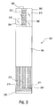
- Figure 3 illustrates an exemplary embodiment of a top view of the test strip shown in Figure 2 ;
- Figure 4 illustrates an exemplary embodiment of a schematic of the functional components of the meter shown in Figure 1A forming an electrical connection with the test strip of Figures 2 and 3 ;
- Figure 5 illustrates an exemplary embodiment of a flow chart of a method of estimating a hematocrit-corrected glucose concentration using the system shown in Figure 1A ;
- Figure 6A illustrates an exemplary embodiment of a chart showing test voltages applied by the meter to the test strip
- Figure 6B illustrates an exemplary embodiment of a chart showing test currents generated when the test voltages of Figure 6A are applied to the test strip;
- Figure 7 illustrates another exemplary embodiment of a flow chart of a method of estimating a hematocrit-corrected glucose concentration using the system shown in Figure 1A ;
- Figure 8A illustrates an exemplary embodiment of a chart showing test voltages applied by the meter to the test strip
- Figure 8B illustrates an exemplary embodiment of a chart showing test currents generated when the test voltages of Figure 8A are applied to the test strip;
- Figure 9 illustrates a bias plot of test data obtained with an end current algorithm
- Figure 10 illustrates a bias plot of test data obtained with a method of the current invention in which the test voltage is applied to the test strip as shown in Figure 6A ;
- Figure 11 illustrates a bias plot of test data obtained with a method of the current invention in which the test voltage is applied to the test strip as shown in Figure 7A .
- Figure 1A illustrates a system 100 for measuring an analyte concentration in which system 100 may include a meter 102 and a test strip 120.
- Meter 102 may include a display 104, a housing 106, a plurality of user interface buttons 108, and a strip port 110.
- Meter 102 further may include electronic circuitry within housing 106 as further described in relation to Figure 1B .
- a proximal portion of test strip 120 may be inserted into strip port 110.
- Display 104 may annunciate an analyte concentration, e.g., glucose concentration, and may be used to show a user interface for prompting a user on how to perform a test.
- an analyte concentration e.g., glucose concentration
- buttons 108 allow a user to operate meter 102 by navigating through the user interface software.
- Display 104 may optionally include a backlight.
- housing 106 Disposed inside housing 106 includes, as shown in Fig. 1B , a circuit board 150 with a microcontroller 162 coupled to a memory 154, clock 156, operational amplifier 158, and display connector 160.
- the op-amp 158 and microcontroller 162 are operatively connected to a strip port connector 152 with contacts 152a, 152b, and 152b for mechanical contact with corresponding conductive tracks on the test strip 120.
- a wireless transceiver module 164 is provided to allow for bi-directional communication of data stored in the memory 154 of the unit 100.
- a power source in the form of a battery (not shown) is provided.
- a data port may also be provided.
- the meter unit 100 is preferably sized and configured to be handheld and the transceiver 164 can be for use with either or both of a short-range wireless network (e.g., BlueTooth or Wi-Fi and the like) or a longer range wireless network (e.g., GSM, CDMA, 3G and the like).
- a short-range wireless network e.g., BlueTooth or Wi-Fi and the like
- a longer range wireless network e.g., GSM, CDMA, 3G and the like.
- Microcontroller 162 can be electrically connected to strip port 152, operational amplifier circuit 158, first wireless module 164, display 104, non-volatile memory 154, clock 156, data port, and user interface buttons 108.
- Data entered via the buttons, transceiver or glucose measurement circuit can include values representative of analyte concentration, or in the context of the analyte concentration values coupled with information, which are related to the everyday lifestyle of an individual.
- Information which is related to the everyday lifestyle, can include food intake, medication use, occurrence of health check-ups, and general health condition and exercise levels of an individual coupled to or "tagged" with the analyte concentration value of the user at specific time of the day or week.
- Operational amplifier circuit 158 can be two or more operational amplifiers configured to provide a portion of the potentiostat function and the current measurement function.
- the potentiostat function can refer to the application of a test voltage between at least two electrodes of a test strip.
- the current function can refer to the measurement of a test current resulting from the applied test voltage to the test strip 120. The current measurement may be performed with a current-to-voltage converter.
- Microcontroller 162 can be in the form of a mixed signal microprocessor (MSP) such as, for example, the Texas Instrument MSP430F2419.
- the TI-MSP430F2419 can be configured to also perform a portion of the potentiostat function and the current measurement function.
- the MSP430F2419 can also include volatile and non-volatile memory.
- many of the electronic components can be integrated with the microcontroller in the form of an application specific integrated circuit (ASIC).
- ASIC application specific integrated circuit
- Strip port 152 can be configured to form an electrical connection to the test strip.
- Display connector 160 can be configured to attach to display 104.
- Display 104 can be in the form of a liquid crystal display for reporting measured glucose levels, and for facilitating entry of lifestyle related information and for manipulation of graphical data, pictorial results and motion video.
- Display 104 may also include a backlight.
- Data port can accept a suitable connector attached to a connecting lead, thereby allowing meter unit 100 to be linked to an external device such as a personal computer.
- Data port can be any port that allows for transmission of data such as, for example, a serial, USB, or a parallel port.
- Clock 156 can be configured for measuring time and be in the form of an oscillating crystal.
- Figures 2 and 3 are exemplary exploded perspective and top assembled views, respectively, of test strip 120, which may include seven layers disposed on a substrate 205.
- the seven layers disposed on substrate 205 may be a conductive layer 250, an insulation layer 216, a reagent layer 218, an adhesive layer 260, a hydrophilic layer 270, and a top layer 280.
- Test strip 120 may be manufactured in a series of steps where the conductive layer 250, insulation layer 216, reagent layer 218, and adhesive layer 260 are sequentially deposited on substrate 205 using, for example, a screen-printing process.
- Hydrophilic layer 270 and top layer 280 may be disposed from a roll stock and laminated onto substrate 205 as either an integrated laminate or as separate layers.
- Test strip 120 has a distal portion 203 and a proximal portion 204, as shown in Figure 2 .
- Test strip 120 may include a sample-receiving chamber 292 through which a blood sample may be drawn.
- Sample-receiving chamber 292 may include an inlet at a proximal end of test strip 120.
- An outlet or air vent is included in hydrophilic layer 270, as will be described below.
- a blood sample may be applied to the inlet to fill a sample-receiving chamber 292 so that an analyte concentration may be measured.
- the side edges of a cutout portion of adhesive layer 260 located adjacent to reagent layer 218 defines a wall of sample-receiving chamber 292, as illustrated in Figure 2 .
- a bottom portion or "floor" of sample-receiving chamber 292 may include a portion of substrate 205, conductive layer 250, and insulation layer 216.
- a top portion or "roof" of sample-receiving chamber 292 may include distal hydrophilic portion 282.
- substrate 205 may be used as a foundation for helping support subsequently applied layers.
- Substrate 205 may be in the form of a polyester sheet such as a polyethylene tetraphthalate (PET) material.
- PET polyethylene tetraphthalate
- Substrate 205 may be in a roll format, nominally 350 microns thick by 370 millimeters wide and approximately 60 meters in length.
- a conductive layer 250 is required for forming electrodes that may be used for the electrochemical measurement of glucose.
- Conductive layer 250 may be made from a carbon ink that is screen-printed onto substrate 205. In a screen-printing process, carbon ink is loaded onto a screen and then transferred through the screen using a squeegee. The printed carbon ink may be dried using hot air at about 140°C.
- the carbon ink may include VAGH resin, carbon black, graphite, and one or more solvents for the resin, carbon and graphite mixture. More particularly, the carbon ink may incorporate a suitable ratio of carbon black: VAGH resin in the carbon ink.
- conductive layer 250 may include a reference electrode 210, a first working electrode 212, a second working electrode 214, a reference contact pad 211, a first contact pad 213, a second contact pad 215, a reference electrode track 207, a first working electrode track 208 and a second working electrode track 209.
- reference electrode 210 is located in between first working electrode 212 and second electrode 214 such that cross-talk between first and second working electrodes 212 and 214 is minimized.
- Conductive layer 250 may be formed from a carbon ink.
- Reference contact pad 211, first contact pad 213 and second contact pad 215 may be configured to electrically connect to a test meter.
- Reference electrode track 207 provides an electrically continuous pathway from reference electrode 210 to reference contact pad 211.
- first working electrode track 208 provides an electrically continuous pathway from first working electrode 12 to first contact pad 213.
- second working electrode track 209 provides an electrically continuous pathway from second working electrode 214 to second contact pad 215.
- Insulation layer 216 may include an aperture 217 that exposes a portion of reference electrode 210, first working electrode 212, and second working electrode 214, which may be wetted by a liquid sample.
- the area of first working electrode 212, second working electrode 214, and reference electrode 210 may be defined as the area exposed to the liquid sample.
- insulation layer 216 prevents a liquid sample from touching the electrode tracks 207, 208, and 209. It is believed that the functional area of a working electrode should be accurately defined because the magnitude of the test current is directly proportional to the effective area of the electrode.
- insulation layer 216 may be Ercon E6110-116 Jet Black InsulayerTM ink that may be purchased from Ercon, Inc.
- the test strip at this point may be treated with plasma.
- the plasma is created by high voltage AC at atmospheric temperatures and pressures.
- the resulting plasma consisting of ionised, highly energetic particles is swept downstream in an air current to impact the substrate.
- Plasma treatment is used to modify the surface of the screen-printed carbon based electrodes. This surface modification is believed to increase the electrochemical activity of the carbon surface and increases the surface energy of the printed layers allowing for better adhesion between them and subsequently printed layers.
- Plasma treatment is also believed to improve the electrochemistry of the carbon surface making the reaction with the mediator more ideal as part of the electrochemical reaction during a measurement cycle.
- Reagent layer 218 is disposed on a portion of conductive layer 250 and insulation layer 216, as illustrated in Figure 2 .
- two overlapping reagent layers may be printed over a portion of conductive layer 250 and insulation layer 216.
- Reagent layer 218 may include chemicals such as an enzyme and a mediator which selectivity reacts with an analyte of interest and a buffer for maintaining a desired pH.
- reagent layer 218 may include an enzyme and a mediator, along with other components necessary for functional operation.
- Enzymatic reagent layer 18 may include, for example, glucose oxidase, trisodium citrate, citric acid, polyvinyl alcohol, hydroxyl ethyl cellulose, potassium ferricyanide, antifoam, cabosil, PVPVA, and water.
- Exemplary enzymes suitable for use in the reagent layer include glucose oxidase, glucose dehydrogenase with a pyrroloquinoline quinone (PQQ) co-factor and glucose dehydrogenase with a flavin adenine dinucleotide (FAD) co-factor.
- An exemplary mediator suitable for use in the reagent layer includes ferricyanide, which in this case is in the oxidized form.
- the reagent layer may be configured to physically transform glucose into an enzymatic by-product and in the process generate an amount of reduced mediator (e.g., ferrocyanide) that is proportional to the glucose concentration value.
- the area of reagent layer 218 is sufficiently large to cover the entire area of reference electrode 210, first working electrode 212 and second working electrode 214.
- Reagent layer 218 includes a width and a length that is sufficiently large to at least account for the largest electrode area that may be used in test strip 120.
- the width of reagent layer 218 may be about 2 millimeters, which is more than double a width of rectangular aperture 217.
- Adhesive layer 260 includes a first adhesive pad 262, a second adhesive pad 264 and a third adhesive pad 266 and may be disposed on test strip 120 after the deposition of reagent layer 218. Portions of adhesive layer 260 may be aligned to be immediately adjacent to, touch, or partially overlap with reagent layer 218. Adhesive layer 260 may include a water based acrylic copolymer pressure sensitive adhesive that is commercially available. Adhesive layer 260 is disposed on a portion of insulation layer 216, conductive layer 250, and substrate 205. Adhesive layer 260 binds hydrophilic layer 270 to test strip 120.
- Hydrophilic layer 270 may include a distal hydrophilic portion 272 and proximal hydrophilic portion 274, as illustrated in Figure 2 .
- a gap 276 is included between distal hydrophilic portion 272 and proximal hydrophilic portion 274. Gap 276 serves as a side vent for air as blood fills sample-receiving chamber 292 (shown in Figure 3 ).
- Hydrophilic layer 270 may be a polyester material having one hydrophilic surface such as an anti-fog coating, which is commercially available from 3M.
- top layer 280 The final layer to be added to test strip 120 is top layer 280, as illustrated in Figure 2 .
- Top layer 280 may include a clear portion 282 and opaque portion 284.
- Top layer 280 is disposed on and adhered to hydrophilic layer 270.
- Top layer 280 may be a polyester that has an adhesive coating on one side. It should be noted that the clear portion 282 substantially overlaps distal hydrophilic portion 272, which allows a user to visually confirm that sample-receiving chamber 292 may be sufficiently filled.
- Opaque portion 238 helps the user observe a high degree of contrast between a colored fluid such as, for example, blood within sample-receiving chamber 292 and opaque portion 284.
- FIG. 4 shows a simplified schematic of meter 102 interfacing with test strip 120.
- Meter 102 may include a reference connector 180, a first connector 182 and a second connector 184, which respectively form an electrical connection to reference contact 211, first contact 213 and second contact 215. The three aforementioned connectors are part of strip port 110.
- a first test voltage source 186 (from the circuit of Fig. 1B ) may apply a test voltage V WE2 between second working electrode 214 and reference electrode 210.
- meter 102 may then measure a test current I WE2 at second working electrode.
- a second test voltage source 188 (from the circuit of Fig.
- test voltage V WE1 applies a test voltage V WE1 between first working electrode 212 and reference electrode 210.
- meter 102 may then measure a test current I WE1 .
- test voltage V WE2 and second test voltage V WE1 may be about equal.
- a method 300 for determining a hematocrit-corrected analyte concentration (e.g., glucose) that uses the aforementioned meter 102 and test strip 120 embodiments will now be described.
- meter 102 and test strip 120 are provided.
- Meter 102 may include electronic circuitry that can be used to apply a first and second test voltage to the test strip and to measure current flowing through the second working electrode 214 and the first working electrode 212, respectively.
- Meter 102 also may include a signal processor with a set of instructions for the method of determining an analyte concentration in a fluid sample as disclosed herein.
- the analyte is blood glucose.
- Figure 6A is an exemplary chart of a test voltage applied to test strip 120.
- test meter 102 Before a fluid sample is applied to test strip 120, test meter 102 is in a fluid detection mode in which a first test voltage of about 400 millivolts is applied between second working electrode 214 and reference electrode 210. A second test voltage of about 400 millivolts is preferably applied simultaneously between first working electrode 212 and reference electrode 210. Alternatively, the second test voltage may also be applied contemporaneously such that a time interval of the application of the first test voltage overlaps with a time interval in the application of the second test voltage.
- the test meter may be in a fluid detection mode during fluid detection time interval t FD prior to the detection of physiological fluid at time t 0 .
- test meter 120 determines when a fluid is applied to test strip 120 in exemplary step 320 such that the fluid wets second working electrode 214 and reference electrode 210. Once test meter 120 recognizes that the physiological fluid has been applied because of, for example, a sufficient increase in the measured test current at second working electrode 214, test meter 120 assigns a zero second marker at time t 0 and starts the test time interval t T . Upon the completion of the test time interval t T , the test voltage is removed. For simplicity, Figure 6A only shows the first test voltage applied to test strip 120.
- Figure 6B is an exemplary chart of current transients (i.e., the measured electrical current response in nanoamperes as a function of time) that are measured when the test voltages of Figure 6A are applied to test strip 120.
- Test currents I i obtained from current transients are generally indicative of the analyte concentration in the sample as will be described in exemplary step 370 below.
- the first test voltage is applied between second working electrode 214 and reference electrode 210 and a second test voltage is applied between first working electrode 212 and reference electrode 210 at time t 0 .
- the first and second test voltages applied to test strip 120 are generally from about +100 millivolts to about +600 millivolts.
- the test voltage is about +400 millivolts.
- Other mediator and electrode material combinations will require different test voltages.
- the duration of the test voltages is generally from about 2 to about 4 seconds after a reaction period and is typically about 3 seconds after a reaction period.
- time t i is measured relative to time t 0 .
- each test current I i is the average of a set of measurements obtained over a short interval, for example, five measurements obtained at 0.01 second intervals starting at t i + 1 , where i ranges from 1 to at least 6.
- first test current I 1 may be measured at about 0.98 seconds to about 1.00 seconds after time t 0
- second test current I 2 may be measured at about 1.98 seconds to about 2.00 seconds after time t 0
- third test current I 3 may be measured at about 2.43 seconds to about 2.45 seconds after time t 0
- fourth test current may be measured at about 2.61 seconds to about 2.63 seconds after time t 0
- fifth test current may be measured at about 2.70 seconds to about 2.72 seconds after time t 0 .
- a is a first tuning parameter from about 9.9 to about 10.2 and b is a second tuning parameter from about 10.8 to about 11.2.
- the hematocrit-corrected glucose concentration may then be annunciated on meter 102.
- FIG. 7 another method 400 for determining a hematocrit-corrected analyte concentration (e.g., glucose) that uses the aforementioned meter 102 and test strip 120 embodiments will now be described.
- a hematocrit-corrected analyte concentration e.g., glucose
- meter 102 and test strip 120 are provided.
- Meter 102 may include electronic circuitry that can be used to apply a first and second test voltage to the test strip and to measure current flowing through the second working electrode 214 and the first working electrode 212, respectively.
- Meter 102 also may include a signal processor with a set of instructions for the method of determining an analyte concentration in a fluid sample as disclosed herein.
- the analyte is blood glucose.
- Figure 8A is an exemplary chart of a test voltage applied to test strip 120.
- test meter 102 Before a fluid sample is applied to test strip 120, test meter 102 is in a fluid detection mode in which a first test voltage of about 400 millivolts is applied between second working electrode 214 and reference electrode 210. A second test voltage of about 400 millivolts is also applied between first working electrode 212 and reference electrode 210.
- the fluid sample is applied to test strip 100 at t 0 and is allowed to react with reagent layer 218 for a reaction period t R . The presence of sample in the reaction zone of test strip 120 is determined by measuring the current flowing through second working electrode 214.
- reaction period t R is determined to begin when the current flowing through second working electrode 214 reaches a desired value, typically about 150 nanoamperes (not shown), at which point a test voltage of about zero millivolts is applied between second working electrode 214 and reference electrode 210 and between first working electrode 212 and reference electrode 210.
- Reaction period t R is typically from about 2 to about 4 seconds after initiation of the measuring and is more typically about 3 seconds after initiation of the measuring, i.e., after t 1 .
- first and second test voltages are applied to test strip 120 at t 1 for a total test time t T .
- Figure 8A only shows the first test voltage applied to test strip 120.
- Figure 8B is an exemplary chart of current transients that are measured when the test voltages of Figure 8A are applied to test strip 120.
- Test currents I i obtained from current transients are generally indicative of the analyte concentration in the sample as will be described in exemplary step 470 below.
- a first test current I 1 , a second test current I 2 ,, a third test current I 3 and a fourth test current I 4 are measured at times t 2 , t 3 , t 4 and t 5 , respectively, at second working electrode 214.
- a fifth test current I 5 is also measured at time t 6 at first working electrode 212.
- the first and second test voltages applied to test strip 120 are generally from about +100 millivolts to about +600 millivolts. In one embodiment in which the electrodes are carbon ink and the mediator is ferricyanide, the test voltages are about +400 millivolts. Other mediator and electrode material combinations may require different test voltages.
- the duration of test voltages is generally from about 4 and 6 seconds after a reaction period and is typically about 5 seconds after a reaction period. Typically, time t i is measured relative to time t 1 .
- each test current I i is the average of a set of measurements obtained over a short interval, for example, five measurements obtained at 0.01 second intervals starting at t i + 1 , where I ranges from 1 to 6.
- a hematocrit-corrected glucose concentration may be determined with Equation 1 as described previously.
- first test current I 1 may be measured at about 3.37 seconds to about 3.39 seconds after reaction period t R
- second test current I 2 may be measured at about 3.46 seconds to about 3.48 seconds after reaction period t R
- third test current I 3 may be measured at about 3.54 seconds to about 3.56 seconds after reaction period t R
- fourth test current may be measured at about 4.05 seconds to about 4.07 seconds after reaction period t R
- fifth test current may be measured at about 4.08 seconds to about 4.10 seconds after reaction period t R .
- a is a first tuning parameter from about 31 to about 33 and b is a second tuning parameter from about 53 to about 55.
- the hematocrit-corrected glucose concentration may then be annunciated on meter 102.
- EXAMPLE 1 Determination of hematocrit-corrected glucose concentration in which no reaction period is allowed for a fluid sample to react with the reagent layer.
- a batch of test strips was tested with 2118 whole blood samples having three different glucose concentrations (i.e., 50 mg/dL, 240 mg/dL and 450 mg/dL) and hematocrit levels ranging from 30 to 55%.
- Test currents were measured at the second working electrode at 0.99, 1.99, 2.44 and 2.62 seconds and at the first working electrode at 2.71 seconds.
- the hematocrit-corrected glucose concentration was determined for each data point as described previously with method 300 (i.e., no reaction period prior to application of the test voltages).
- Empirically derived tuning parameters a and b having values of 10.05 and 10.99, respectively, were used in Equation 1 to determine the hematocrit-corrected glucose concentration along with an empirically derived slope of 0.0136 and an intercept of 0.312.
- An uncorrected glucose concentration was also determined for over two thousands whole blood samples (specifically about 2122 samples) having three different glucose concentrations (i.e., 50 mg/dL, 240 mg/dL and 450 mg/dL) and hematocrit levels ranging from 30 to 55%.
- the same batch of test strips was used.
- a test current at 5 seconds (hereinafter called the "end current") was measured and recorded for each sample.
- the uncorrected glucose concentration was then determined from a calibration curve table stored in the meter.
- a calibration curve may be generated from the end current data by graphing end current as a function of known glucose concentration as measured on a reference instrument.
- EXAMPLE 2 Determination of hematocrit-corrected glucose concentration in which a fluid sample is allowed to react with the reagent layer for a reaction period.
- Example 2 The same batch of test strips as used in Example 1 was tested with approximately 2150 whole blood samples having three different glucose concentrations (i.e., 50 mg/dL, 240 mg/dL and 450 mg/dL) and hematocrit levels ranging from about 30% to about 55%. Test currents were measured at the second working electrode at approximately 3.4, 3.5, 3.6 and 4.1 seconds and at the first working electrode at 4.1 seconds. The hematocrit-corrected glucose concentration was determined for each data point as described previously with method 400 (i.e., reaction period prior to application of the test voltages).
- Empirically derived tuning parameters a and b having values of approximately 32.03 and 53.96, respectively, were used in Equation 1 to determine the hematocrit-corrected glucose concentration along with an empirically derived slope of approximately 0.0103 and an intercept of approximately 0.377.
- bias which is an estimate of the relative error in the glucose measurement
- Bias abs is absolute bias
- Bias % is percent bias
- G calculated is the glucose concentration determined by one of three methods described in Examples 1 and 2 and G reference is the reference glucose concentration.
- Figures 9 , 10 and 11 illustrate bias plots of bias versus percent hematocrit.
- Figure 9 illustrates the bias plot of data in which the end current was used to determine the glucose concentration.
- Figure 10 illustrates the bias plot of data as determined by method 300 (i.e., no reaction period prior to application of the test voltages).
- Figure 11 illustrates the bias plot of data as determined by method 400 (i.e., reaction period prior to application of the test voltages).
- Table 1 Summary of Bias Results ISO Bias Criteria Approx. (%) Percent within Bias Criteria for Endpoint algorithm Percent within Bias Criteria for Method 300 Percent within Bias Criteria for Method 400 +/- 20 96.7 100 99.7 +/- 15 84.0 97.4 96.0 +/- 10 68.4 85.7 83.3
- Table 1 indicates an increase in the percent of data falling within each ISO bias criteria when methods 300 and 400 are used to correct the data for the hematocrit effect.
- the system and methods described and illustrated herein can be used to determine a hematocrit-corrected glucose concentration.
- the glucose result obtained with the exemplary subject system and method is believed to be more accurate.
Landscapes
- Health & Medical Sciences (AREA)
- Life Sciences & Earth Sciences (AREA)
- Chemical & Material Sciences (AREA)
- Physics & Mathematics (AREA)
- General Health & Medical Sciences (AREA)
- Engineering & Computer Science (AREA)
- Molecular Biology (AREA)
- General Physics & Mathematics (AREA)
- Pathology (AREA)
- Immunology (AREA)
- Analytical Chemistry (AREA)
- Biochemistry (AREA)
- Hematology (AREA)
- Chemical Kinetics & Catalysis (AREA)
- Electrochemistry (AREA)
- Biomedical Technology (AREA)
- Biophysics (AREA)
- Medicinal Chemistry (AREA)
- Food Science & Technology (AREA)
- Urology & Nephrology (AREA)
- Ecology (AREA)
- Bioinformatics & Cheminformatics (AREA)
- Bioinformatics & Computational Biology (AREA)
- Biotechnology (AREA)
- Evolutionary Biology (AREA)
- Medical Informatics (AREA)
- Spectroscopy & Molecular Physics (AREA)
- Theoretical Computer Science (AREA)
- Investigating Or Analysing Biological Materials (AREA)
Abstract
Description
- This application claims the benefits of priority under 35 USC§ 119 and/or §120 from prior filed
U.S. Provisional Application Serial No. 61/319,470 filed on March 31, 2010 - Electrochemical sensors have been used to detect or measure the presence of substances in fluid samples. Electrochemical sensors include a reagent mixture containing at least an electron transfer agent (also referred to as an "electron mediator") and an analyte specific bio-catalytic protein (e.g. a particular enzyme), and one or more electrodes. Such sensors rely on electron transfer between the electron mediator and the electrode surfaces and function by measuring electrochemical redox reactions. When used in an electrochemical biosensor system or device, the electron transfer reactions are monitored via an electrical signal that correlates to the concentration of the analyte being measured in the fluid sample.
- The use of such electrochemical sensors to detect analytes in bodily fluids, such as blood or blood derived products, tears, urine, and saliva, has become important, and in some cases, vital to maintain the health of certain individuals. In the health care field, people such as diabetics, for example, must monitor a particular constituent within their bodily fluids. A number of systems are capable of testing a body fluid, such as, blood, urine, or saliva, to conveniently monitor the level of a particular fluid constituent, such as, cholesterol, proteins, and glucose. Patients suffering from diabetes, a disorder of the pancreas where insufficient insulin production prevents the proper digestion of sugar, have a need to carefully monitor their blood glucose levels on a daily basis. Routine testing and controlling blood glucose for people with diabetes can reduce their risk of serious damage to the eyes, nerves, and kidneys.
- Electrochemical biosensors may be adversely affected by the presence of certain blood components that may undesirably affect the measurement and lead to inaccuracies in the detected signal. This inaccuracy may result in an inaccurate glucose reading, leaving the patient unaware of a potentially dangerous blood sugar level, for example. As one example, the blood hematocrit level (i.e. the percentage of the amount of blood that is occupied by red blood cells) can erroneously affect a resulting analyte concentration measurement.
- Variations in a volume of red blood cells within blood can cause variations in glucose readings measured with disposable electrochemical test strips. Typically, a negative bias (i.e., lower calculated analyte concentration) is observed at high hematocrit, while a positive bias (i.e., higher calculated analyte concentration) is observed at low hematocrit. At high hematocrit, for example, the red blood cells may impede the reaction of enzymes and electrochemical mediators, reduce the rate of chemistry dissolution since there less plasma volume to solvate the chemical reactants, and slow diffusion of the mediator. These factors can result in a lower than expected glucose reading as less current is produced during the electrochemical process. Conversely, at low hematocrit, fewer red blood cells may affect the electrochemical reaction than expected, and a higher measured current can result. In addition, the blood sample resistance is also hematocrit dependent, which can affect voltage and/or current measurements.
- Several strategies have been used to reduce or avoid hematocrit based variations on blood glucose. For example, test strips have been designed to incorporate meshes to remove red blood cells from the samples, or have included various compounds or formulations designed to increase the viscosity of red blood cell and attenuate the affect of low hematocrit on concentration determinations. Other test strips have included lysis agents and systems configured to determine hemoglobin concentration in an attempt to correct hematocrit. Further, biosensors have been configured to measure hematocrit by measuring optical variations after irradiating the blood sample with light, or measuring hematocrit based on a function of sample chamber fill time. These sensors have certain disadvantages.
- Applicants have recognized a need for a system and method that can be used to determine an accurate glucose concentration that avoids the disadvantages in the field.
- In view of the foregoing and in accordance with one aspect, there is provided a method of operating an analyte measurement system having a meter and a test strip. The test strip may include a reference electrode, a first working electrode and a second working electrode in which the first electrodes are coated with a reagent layer. The meter may include an electronic circuit for applying a test voltage between the reference electrode and the first working electrode and for applying a second test voltage between the reference electrode and the second working electrode. The meter also may include a signal processor for measuring a plurality of test currents and for calculating a glucose concentration from the test currents. The method may be achieved by applying a first test voltage between the reference electrode and the second working electrode and applying a second test voltage between the reference electrode and the first working electrode; measuring a first test current, a second test current, a third test current and a fourth test current at the second working electrode after a blood sample containing an analyte is applied to the test strip; measuring a fifth test current at the first working electrode; ascertaining the glucose concentration from the first, second, third, fourth and fifth test currents; and annunciating the glucose concentration.
- In the exemplary method, the glucose concentration may be a value obtained with the following:

where: - G is the hematocrit-corrected glucose concentration;
- I 1 is the first test current;
- I 2 is the second test current;
- I 3 is the third test current;
- I 4 is the second test current;
- I 5 is the third test current;
- a and b are tuning parameters that are empirically derived;
- intercept is an intercept value determined from a linear regression of a plot of

- slope is a slope value determined from a linear regression of a plot of

- In an embodiment in which first and second test voltages are applied to the test strip as soon as a test fluid is detected, the first tuning parameter a may be from about 9.5 to about 10.5 and the second tuning parameter b may be from about 10.5 and 11.5. In another embodiment in which first and second test voltages are applied to the test strip after the test fluid is allowed to react for a period of time with the reagent layer, first tuning parameter a may be from about 31.5 to about 32.5 and second tuning parameter b may be from about 53.5 and 54.5.
- In yet a further embodiment, a method for determining a hematocrit-corrected test current measurable with a system having a test strip and a meter is provided. The method can be achieved by applying a first test voltage between a reference electrode and a second working electrode coated with a reagent layer and applying a second test voltage between the reference electrode and a first working electrode; measuring a first test current, a second test current, a third test current and a fourth test current at the second working electrode after a blood sample containing an analyte is applied to the test strip; measuring a fifth test current at the first working electrode and ascertaining a hematocrit-corrected test current via a ratio of the first test current to the second test current raised to a power term and multiplying the ratio by the fifth test current, in which the power term is a function of a first tuning parameter and a second tuning parameter.
- In yet a further embodiment, an analyte measurement system to measure at least glucose concentration in physiological fluid of a user is provided. The system includes a test strip and a meter. The test strip includes a substrate having a reference electrode, a first working electrode and a second working electrode, all of which are coated with a reagent layer. The electrodes are connected to corresponding contact pads. The analyte meter has a test circuit in connection with a test strip port that receives the contact pads of the test strip so that the meter is configured to apply first and second test voltages to respective second and first working electrode after deposition of physiological fluid on the electrodes and to determine a hematocrit-corrected glucose concentration from measured first, second, third, fourth and fifth test currents at first, second, third, fourth and fifth discrete intervals after application of the test voltages by the meter.
- These and other embodiments, features and advantages of the invention will become apparent to those skilled in the art when taken with reference to the following more detailed description of the exemplary embodiments in conjunction with the accompanying drawings that are first briefly described.
- The accompanying drawings, which are incorporated herein and constitute part of this specification, illustrate presently preferred embodiments of the invention, and, together with the general description given above and the detailed description given below, serve to explain features of the invention (in which like numerals represent like elements), of which:
-
Figure 1A illustrates an exemplary embodiment of a top view of a system for measuring an analyte concentration; -
Figure 1B illustrates an exemplary circuit board of the electrical components disposed in the analyte measurement device ofFigure 1A . -
Figure 2 illustrates an exemplary embodiment of a perspective exploded view of a test strip; -
Figure 3 illustrates an exemplary embodiment of a top view of the test strip shown inFigure 2 ; -
Figure 4 illustrates an exemplary embodiment of a schematic of the functional components of the meter shown inFigure 1A forming an electrical connection with the test strip ofFigures 2 and3 ; -
Figure 5 illustrates an exemplary embodiment of a flow chart of a method of estimating a hematocrit-corrected glucose concentration using the system shown inFigure 1A ; -
Figure 6A illustrates an exemplary embodiment of a chart showing test voltages applied by the meter to the test strip; -
Figure 6B illustrates an exemplary embodiment of a chart showing test currents generated when the test voltages ofFigure 6A are applied to the test strip; -
Figure 7 illustrates another exemplary embodiment of a flow chart of a method of estimating a hematocrit-corrected glucose concentration using the system shown inFigure 1A ; -
Figure 8A illustrates an exemplary embodiment of a chart showing test voltages applied by the meter to the test strip; -
Figure 8B illustrates an exemplary embodiment of a chart showing test currents generated when the test voltages ofFigure 8A are applied to the test strip; -
Figure 9 illustrates a bias plot of test data obtained with an end current algorithm; -
Figure 10 illustrates a bias plot of test data obtained with a method of the current invention in which the test voltage is applied to the test strip as shown inFigure 6A ; and -
Figure 11 illustrates a bias plot of test data obtained with a method of the current invention in which the test voltage is applied to the test strip as shown inFigure 7A . - The following detailed description should be read with reference to the drawings, in which like elements in different drawings are identically numbered. The drawings, which are not necessarily to scale, depict selected embodiments and are not intended to limit the scope of the invention. The detailed description illustrates by way of example, not by way of limitation, the principles of the invention. This description will clearly enable one skilled in the art to make and use the invention, and describes several embodiments, adaptations, variations, alternatives and uses of the invention, including what is presently believed to be the best mode of carrying out the invention.
-
Figure 1A illustrates asystem 100 for measuring an analyte concentration in whichsystem 100 may include ameter 102 and atest strip 120.Meter 102 may include adisplay 104, ahousing 106, a plurality ofuser interface buttons 108, and astrip port 110.Meter 102 further may include electronic circuitry withinhousing 106 as further described in relation toFigure 1B . A proximal portion oftest strip 120 may be inserted intostrip port 110.Display 104 may annunciate an analyte concentration, e.g., glucose concentration, and may be used to show a user interface for prompting a user on how to perform a test. As used here, the term "annunciate" and variations on the root term indicate that an announcement may be provided via text, audio, visual or a combination of all modes of communication to a user, a caretaker of the user, or a healthcare provider. The plurality ofuser interface buttons 108 allow a user to operatemeter 102 by navigating through the user interface software.Display 104 may optionally include a backlight. - Disposed inside
housing 106 includes, as shown inFig. 1B , acircuit board 150 with amicrocontroller 162 coupled to amemory 154,clock 156,operational amplifier 158, anddisplay connector 160. The op-amp 158 andmicrocontroller 162 are operatively connected to astrip port connector 152 withcontacts test strip 120. To facilitate communication with other data management devices, awireless transceiver module 164 is provided to allow for bi-directional communication of data stored in thememory 154 of theunit 100. On the other side of circuit board 150 a power source in the form of a battery (not shown) is provided. A data port may also be provided. It should be noted that themeter unit 100 is preferably sized and configured to be handheld and thetransceiver 164 can be for use with either or both of a short-range wireless network (e.g., BlueTooth or Wi-Fi and the like) or a longer range wireless network (e.g., GSM, CDMA, 3G and the like). -
Microcontroller 162 can be electrically connected to stripport 152,operational amplifier circuit 158,first wireless module 164,display 104,non-volatile memory 154,clock 156, data port, anduser interface buttons 108. Data entered via the buttons, transceiver or glucose measurement circuit can include values representative of analyte concentration, or in the context of the analyte concentration values coupled with information, which are related to the everyday lifestyle of an individual. Information, which is related to the everyday lifestyle, can include food intake, medication use, occurrence of health check-ups, and general health condition and exercise levels of an individual coupled to or "tagged" with the analyte concentration value of the user at specific time of the day or week. -
Operational amplifier circuit 158 can be two or more operational amplifiers configured to provide a portion of the potentiostat function and the current measurement function. The potentiostat function can refer to the application of a test voltage between at least two electrodes of a test strip. The current function can refer to the measurement of a test current resulting from the applied test voltage to thetest strip 120. The current measurement may be performed with a current-to-voltage converter.Microcontroller 162 can be in the form of a mixed signal microprocessor (MSP) such as, for example, the Texas Instrument MSP430F2419. The TI-MSP430F2419 can be configured to also perform a portion of the potentiostat function and the current measurement function. In addition, the MSP430F2419 can also include volatile and non-volatile memory. In another embodiment, many of the electronic components can be integrated with the microcontroller in the form of an application specific integrated circuit (ASIC). -
Strip port 152 can be configured to form an electrical connection to the test strip.Display connector 160 can be configured to attach to display 104.Display 104 can be in the form of a liquid crystal display for reporting measured glucose levels, and for facilitating entry of lifestyle related information and for manipulation of graphical data, pictorial results and motion video.Display 104 may also include a backlight. Data port can accept a suitable connector attached to a connecting lead, thereby allowingmeter unit 100 to be linked to an external device such as a personal computer. Data port can be any port that allows for transmission of data such as, for example, a serial, USB, or a parallel port.Clock 156 can be configured for measuring time and be in the form of an oscillating crystal. -
Figures 2 and3 are exemplary exploded perspective and top assembled views, respectively, oftest strip 120, which may include seven layers disposed on asubstrate 205. The seven layers disposed onsubstrate 205 may be aconductive layer 250, aninsulation layer 216, areagent layer 218, anadhesive layer 260, ahydrophilic layer 270, and atop layer 280.Test strip 120 may be manufactured in a series of steps where theconductive layer 250,insulation layer 216,reagent layer 218, andadhesive layer 260 are sequentially deposited onsubstrate 205 using, for example, a screen-printing process.Hydrophilic layer 270 andtop layer 280 may be disposed from a roll stock and laminated ontosubstrate 205 as either an integrated laminate or as separate layers.Test strip 120 has adistal portion 203 and aproximal portion 204, as shown inFigure 2 . -
Test strip 120 may include a sample-receivingchamber 292 through which a blood sample may be drawn. Sample-receivingchamber 292 may include an inlet at a proximal end oftest strip 120. An outlet or air vent is included inhydrophilic layer 270, as will be described below. A blood sample may be applied to the inlet to fill a sample-receivingchamber 292 so that an analyte concentration may be measured. The side edges of a cutout portion ofadhesive layer 260 located adjacent toreagent layer 218 defines a wall of sample-receivingchamber 292, as illustrated inFigure 2 . A bottom portion or "floor" of sample-receivingchamber 292 may include a portion ofsubstrate 205,conductive layer 250, andinsulation layer 216. A top portion or "roof" of sample-receivingchamber 292 may include distalhydrophilic portion 282. - For
test strip 120, as illustrated inFigure 2 ,substrate 205 may be used as a foundation for helping support subsequently applied layers.Substrate 205 may be in the form of a polyester sheet such as a polyethylene tetraphthalate (PET) material.Substrate 205 may be in a roll format, nominally 350 microns thick by 370 millimeters wide and approximately 60 meters in length. - A
conductive layer 250 is required for forming electrodes that may be used for the electrochemical measurement of glucose.Conductive layer 250 may be made from a carbon ink that is screen-printed ontosubstrate 205. In a screen-printing process, carbon ink is loaded onto a screen and then transferred through the screen using a squeegee. The printed carbon ink may be dried using hot air at about 140°C. The carbon ink may include VAGH resin, carbon black, graphite, and one or more solvents for the resin, carbon and graphite mixture. More particularly, the carbon ink may incorporate a suitable ratio of carbon black: VAGH resin in the carbon ink. - For
test strip 120, as illustrated inFigure 2 ,conductive layer 250 may include areference electrode 210, a first workingelectrode 212, asecond working electrode 214, areference contact pad 211, afirst contact pad 213, asecond contact pad 215, areference electrode track 207, a first workingelectrode track 208 and a secondworking electrode track 209. In the embodiment shown inFigure 2 ,reference electrode 210 is located in between first workingelectrode 212 andsecond electrode 214 such that cross-talk between first and second workingelectrodes -
Conductive layer 250 may be formed from a carbon ink.Reference contact pad 211,first contact pad 213 andsecond contact pad 215 may be configured to electrically connect to a test meter.Reference electrode track 207 provides an electrically continuous pathway fromreference electrode 210 toreference contact pad 211. Similarly, first workingelectrode track 208 provides an electrically continuous pathway from first workingelectrode 12 tofirst contact pad 213. Similarly, second workingelectrode track 209 provides an electrically continuous pathway from second workingelectrode 214 tosecond contact pad 215. -
Insulation layer 216 may include anaperture 217 that exposes a portion ofreference electrode 210, first workingelectrode 212, and second workingelectrode 214, which may be wetted by a liquid sample. The area of first workingelectrode 212, second workingelectrode 214, andreference electrode 210 may be defined as the area exposed to the liquid sample. In addition to defining an electrode area,insulation layer 216 prevents a liquid sample from touching the electrode tracks 207, 208, and 209. It is believed that the functional area of a working electrode should be accurately defined because the magnitude of the test current is directly proportional to the effective area of the electrode. As an example,insulation layer 216 may be Ercon E6110-116 Jet Black Insulayer™ ink that may be purchased from Ercon, Inc. The test strip at this point may be treated with plasma. The plasma is created by high voltage AC at atmospheric temperatures and pressures. The resulting plasma, consisting of ionised, highly energetic particles is swept downstream in an air current to impact the substrate. Plasma treatment is used to modify the surface of the screen-printed carbon based electrodes. This surface modification is believed to increase the electrochemical activity of the carbon surface and increases the surface energy of the printed layers allowing for better adhesion between them and subsequently printed layers. Plasma treatment is also believed to improve the electrochemistry of the carbon surface making the reaction with the mediator more ideal as part of the electrochemical reaction during a measurement cycle. -
Reagent layer 218 is disposed on a portion ofconductive layer 250 andinsulation layer 216, as illustrated inFigure 2 . In an embodiment, two overlapping reagent layers may be printed over a portion ofconductive layer 250 andinsulation layer 216. -
Reagent layer 218 may include chemicals such as an enzyme and a mediator which selectivity reacts with an analyte of interest and a buffer for maintaining a desired pH. For example, if glucose is to be determined in a blood sample,reagent layer 218 may include an enzyme and a mediator, along with other components necessary for functional operation. Enzymatic reagent layer 18 may include, for example, glucose oxidase, trisodium citrate, citric acid, polyvinyl alcohol, hydroxyl ethyl cellulose, potassium ferricyanide, antifoam, cabosil, PVPVA, and water. - Exemplary enzymes suitable for use in the reagent layer include glucose oxidase, glucose dehydrogenase with a pyrroloquinoline quinone (PQQ) co-factor and glucose dehydrogenase with a flavin adenine dinucleotide (FAD) co-factor. An exemplary mediator suitable for use in the reagent layer includes ferricyanide, which in this case is in the oxidized form. The reagent layer may be configured to physically transform glucose into an enzymatic by-product and in the process generate an amount of reduced mediator (e.g., ferrocyanide) that is proportional to the glucose concentration value. Further details regarding reagent layers, and electrochemical-based analytical test strips in general, are in
U.S. Patent No. 6,241,862 , the contents of which are hereby fully incorporated by reference. - In one embodiment, the area of
reagent layer 218 is sufficiently large to cover the entire area ofreference electrode 210, first workingelectrode 212 and second workingelectrode 214.Reagent layer 218 includes a width and a length that is sufficiently large to at least account for the largest electrode area that may be used intest strip 120. The width ofreagent layer 218 may be about 2 millimeters, which is more than double a width ofrectangular aperture 217. -
Adhesive layer 260 includes a firstadhesive pad 262, a secondadhesive pad 264 and a thirdadhesive pad 266 and may be disposed ontest strip 120 after the deposition ofreagent layer 218. Portions ofadhesive layer 260 may be aligned to be immediately adjacent to, touch, or partially overlap withreagent layer 218.Adhesive layer 260 may include a water based acrylic copolymer pressure sensitive adhesive that is commercially available.Adhesive layer 260 is disposed on a portion ofinsulation layer 216,conductive layer 250, andsubstrate 205.Adhesive layer 260 bindshydrophilic layer 270 totest strip 120. -
Hydrophilic layer 270 may include a distalhydrophilic portion 272 and proximalhydrophilic portion 274, as illustrated inFigure 2 . Agap 276 is included between distalhydrophilic portion 272 and proximalhydrophilic portion 274.Gap 276 serves as a side vent for air as blood fills sample-receiving chamber 292 (shown inFigure 3 ).Hydrophilic layer 270 may be a polyester material having one hydrophilic surface such as an anti-fog coating, which is commercially available from 3M. - The final layer to be added to
test strip 120 istop layer 280, as illustrated inFigure 2 .Top layer 280 may include aclear portion 282 andopaque portion 284.Top layer 280 is disposed on and adhered tohydrophilic layer 270.Top layer 280 may be a polyester that has an adhesive coating on one side. It should be noted that theclear portion 282 substantially overlaps distalhydrophilic portion 272, which allows a user to visually confirm that sample-receivingchamber 292 may be sufficiently filled. Opaque portion 238 helps the user observe a high degree of contrast between a colored fluid such as, for example, blood within sample-receivingchamber 292 andopaque portion 284. -
Figure 4 shows a simplified schematic ofmeter 102 interfacing withtest strip 120.Meter 102 may include areference connector 180, afirst connector 182 and asecond connector 184, which respectively form an electrical connection toreference contact 211,first contact 213 andsecond contact 215. The three aforementioned connectors are part ofstrip port 110. When performing a test, a first test voltage source 186 (from the circuit ofFig. 1B ) may apply a test voltage V WE2 between second workingelectrode 214 andreference electrode 210. As a result of test voltage V WE2,meter 102 may then measure a test current I WE2 at second working electrode. In a similar manner, a second test voltage source 188 (from the circuit ofFig. 1B ) applies a test voltage V WE1 between first workingelectrode 212 andreference electrode 210. As a result of test voltage V WE1, meter 102 may then measure a test current I WE1. In an embodiment, test voltage V WE2 and second test voltage V WE1 may be about equal. - Referring to
Figure 5 , amethod 300 for determining a hematocrit-corrected analyte concentration (e.g., glucose) that uses theaforementioned meter 102 andtest strip 120 embodiments will now be described. - In
exemplary step 310,meter 102 andtest strip 120 are provided.Meter 102 may include electronic circuitry that can be used to apply a first and second test voltage to the test strip and to measure current flowing through the second workingelectrode 214 and the first workingelectrode 212, respectively.Meter 102 also may include a signal processor with a set of instructions for the method of determining an analyte concentration in a fluid sample as disclosed herein. In one embodiment, the analyte is blood glucose. -
Figure 6A is an exemplary chart of a test voltage applied totest strip 120. Before a fluid sample is applied totest strip 120,test meter 102 is in a fluid detection mode in which a first test voltage of about 400 millivolts is applied between second workingelectrode 214 andreference electrode 210. A second test voltage of about 400 millivolts is preferably applied simultaneously between first workingelectrode 212 andreference electrode 210. Alternatively, the second test voltage may also be applied contemporaneously such that a time interval of the application of the first test voltage overlaps with a time interval in the application of the second test voltage. The test meter may be in a fluid detection mode during fluid detection time interval t FD prior to the detection of physiological fluid at time t 0. In the fluid detection mode,test meter 120 determines when a fluid is applied totest strip 120 inexemplary step 320 such that the fluid wets second workingelectrode 214 andreference electrode 210. Oncetest meter 120 recognizes that the physiological fluid has been applied because of, for example, a sufficient increase in the measured test current at second workingelectrode 214,test meter 120 assigns a zero second marker at time t 0 and starts the test time interval t T . Upon the completion of the test time interval t T , the test voltage is removed. For simplicity,Figure 6A only shows the first test voltage applied totest strip 120. -
Figure 6B is an exemplary chart of current transients (i.e., the measured electrical current response in nanoamperes as a function of time) that are measured when the test voltages ofFigure 6A are applied totest strip 120. Test currents I i obtained from current transients are generally indicative of the analyte concentration in the sample as will be described in exemplary step 370 below. Referring toFigures 5 and6A , inexemplary step 330, the first test voltage is applied between second workingelectrode 214 andreference electrode 210 and a second test voltage is applied between first workingelectrode 212 andreference electrode 210 at time t0 . Inexemplary step 340, a first test current I 1, a second test current I 2 , a third test current I 3 and a fourth test current I 4 are measured at times t 2, t 3, t 4 and t 5 , respectively, at second workingelectrode 214. These currents I i where i=1, 2, 3, 4 ... n are stored or recorded in the memory unit of the meter for analysis. Inexemplary step 340, a fifth test current I 5 is also measured at time t 6 at first workingelectrode 212. The first and second test voltages applied totest strip 120 are generally from about +100 millivolts to about +600 millivolts. In one embodiment in which the electrodes include carbon ink and the mediator is ferricyanide, the test voltage is about +400 millivolts. Other mediator and electrode material combinations will require different test voltages. The duration of the test voltages is generally from about 2 to about 4 seconds after a reaction period and is typically about 3 seconds after a reaction period. Typically, time t i is measured relative to time t 0 . In practice, each test current I i is the average of a set of measurements obtained over a short interval, for example, five measurements obtained at 0.01 second intervals starting at t i+1 , where i ranges from 1 to at least 6. - Referring to
Figure 5 inexemplary step 350, a hematocrit-corrected glucose concentration may be determined with the following:
where: - G is the hematocrit-corrected glucose concentration;
- I 1 is the first test current;
- I 2 is the second test current;
- I 3 is the third test current;
- I 4 is the second test current;
- I 5 is the third test current;
- a and b are tuning parameters that are empirically derived;
- intercept is an intercept value determined from a linear regression of a plot of

- slope is a slope value determined from a linear regression of a plot of

- In an embodiment, first test current I 1 may be measured at about 0.98 seconds to about 1.00 seconds after time t 0 , second test current I 2 may be measured at about 1.98 seconds to about 2.00 seconds after time t 0, third test current I 3 may be measured at about 2.43 seconds to about 2.45 seconds after time t0 , fourth test current may be measured at about 2.61 seconds to about 2.63 seconds after time t 0 and fifth test current may be measured at about 2.70 seconds to about 2.72 seconds after time t 0 .
- In an embodiment, a is a first tuning parameter from about 9.9 to about 10.2 and b is a second tuning parameter from about 10.8 to about 11.2.
- In
exemplary step 360, the hematocrit-corrected glucose concentration may then be annunciated onmeter 102. - Referring to
Figure 7 , anothermethod 400 for determining a hematocrit-corrected analyte concentration (e.g., glucose) that uses theaforementioned meter 102 andtest strip 120 embodiments will now be described. - In
exemplary step 410,meter 102 andtest strip 120 are provided.Meter 102 may include electronic circuitry that can be used to apply a first and second test voltage to the test strip and to measure current flowing through the second workingelectrode 214 and the first workingelectrode 212, respectively.Meter 102 also may include a signal processor with a set of instructions for the method of determining an analyte concentration in a fluid sample as disclosed herein. In one embodiment, the analyte is blood glucose. -
Figure 8A is an exemplary chart of a test voltage applied totest strip 120. Before a fluid sample is applied totest strip 120,test meter 102 is in a fluid detection mode in which a first test voltage of about 400 millivolts is applied between second workingelectrode 214 andreference electrode 210. A second test voltage of about 400 millivolts is also applied between first workingelectrode 212 andreference electrode 210. Inexemplary step 420, the fluid sample is applied totest strip 100 at t 0 and is allowed to react withreagent layer 218 for a reaction period t R . The presence of sample in the reaction zone oftest strip 120 is determined by measuring the current flowing through second workingelectrode 214. The beginning of reaction period t R is determined to begin when the current flowing through second workingelectrode 214 reaches a desired value, typically about 150 nanoamperes (not shown), at which point a test voltage of about zero millivolts is applied between second workingelectrode 214 andreference electrode 210 and between first workingelectrode 212 andreference electrode 210. Reaction period t R is typically from about 2 to about 4 seconds after initiation of the measuring and is more typically about 3 seconds after initiation of the measuring, i.e., after t 1 . Inexemplary step 430, after reaction period t R , first and second test voltages are applied totest strip 120 at t 1 for a total test time t T . For simplicity,Figure 8A only shows the first test voltage applied totest strip 120. -
Figure 8B is an exemplary chart of current transients that are measured when the test voltages ofFigure 8A are applied totest strip 120. Test currents Ii obtained from current transients are generally indicative of the analyte concentration in the sample as will be described in exemplary step 470 below. Referring toFigures 7 and8A , inexemplary step 440, after the first and second test voltages are applied totest strip 120 at time t1 , a first test current I 1, a second test current I 2 ,, a third test current I 3 and a fourth test current I 4 are measured at times t 2, t 3, t 4 and t5 , respectively, at second workingelectrode 214. Inexemplary step 440, a fifth test current I 5 is also measured at time t 6 at first workingelectrode 212. The first and second test voltages applied totest strip 120 are generally from about +100 millivolts to about +600 millivolts. In one embodiment in which the electrodes are carbon ink and the mediator is ferricyanide, the test voltages are about +400 millivolts. Other mediator and electrode material combinations may require different test voltages. The duration of test voltages is generally from about 4 and 6 seconds after a reaction period and is typically about 5 seconds after a reaction period. Typically, time t i is measured relative to time t 1 . In practice, each test current I i is the average of a set of measurements obtained over a short interval, for example, five measurements obtained at 0.01 second intervals starting at t i+1 , where I ranges from 1 to 6. - Referring to
Figure 7 , in exemplary step 470, a hematocrit-corrected glucose concentration may be determined withEquation 1 as described previously. - In an embodiment, first test current I 1 may be measured at about 3.37 seconds to about 3.39 seconds after reaction period t R , second test current I 2 may be measured at about 3.46 seconds to about 3.48 seconds after reaction period t R , third test current I 3 may be measured at about 3.54 seconds to about 3.56 seconds after reaction period t R , fourth test current may be measured at about 4.05 seconds to about 4.07 seconds after reaction period t R and fifth test current may be measured at about 4.08 seconds to about 4.10 seconds after reaction period t R .
- In an embodiment, a is a first tuning parameter from about 31 to about 33 and b is a second tuning parameter from about 53 to about 55.
- In exemplary step 480, the hematocrit-corrected glucose concentration may then be annunciated on
meter 102. - A batch of test strips was tested with 2118 whole blood samples having three different glucose concentrations (i.e., 50 mg/dL, 240 mg/dL and 450 mg/dL) and hematocrit levels ranging from 30 to 55%. Test currents were measured at the second working electrode at 0.99, 1.99, 2.44 and 2.62 seconds and at the first working electrode at 2.71 seconds. The hematocrit-corrected glucose concentration was determined for each data point as described previously with method 300 (i.e., no reaction period prior to application of the test voltages). Empirically derived tuning parameters a and b having values of 10.05 and 10.99, respectively, were used in
Equation 1 to determine the hematocrit-corrected glucose concentration along with an empirically derived slope of 0.0136 and an intercept of 0.312. - An uncorrected glucose concentration was also determined for over two thousands whole blood samples (specifically about 2122 samples) having three different glucose concentrations (i.e., 50 mg/dL, 240 mg/dL and 450 mg/dL) and hematocrit levels ranging from 30 to 55%. The same batch of test strips was used. A test current at 5 seconds (hereinafter called the "end current") was measured and recorded for each sample. The uncorrected glucose concentration was then determined from a calibration curve table stored in the meter. A calibration curve may be generated from the end current data by graphing end current as a function of known glucose concentration as measured on a reference instrument.
- The same batch of test strips as used in Example 1 was tested with approximately 2150 whole blood samples having three different glucose concentrations (i.e., 50 mg/dL, 240 mg/dL and 450 mg/dL) and hematocrit levels ranging from about 30% to about 55%. Test currents were measured at the second working electrode at approximately 3.4, 3.5, 3.6 and 4.1 seconds and at the first working electrode at 4.1 seconds. The hematocrit-corrected glucose concentration was determined for each data point as described previously with method 400 (i.e., reaction period prior to application of the test voltages). Empirically derived tuning parameters a and b having values of approximately 32.03 and 53.96, respectively, were used in
Equation 1 to determine the hematocrit-corrected glucose concentration along with an empirically derived slope of approximately 0.0103 and an intercept of approximately 0.377. - The bias, which is an estimate of the relative error in the glucose measurement, was next calculated for each glucose concentration determined with the three methods described in Examples 1 and 2 (i.e., endpoint current,
method 300 and method 400). The bias for each glucose concentration was determined with equations of the form:

- where Bias abs is absolute bias, Bias % is percent bias, G calculated is the glucose concentration determined by one of three methods described in Examples 1 and 2 and G reference is the reference glucose concentration.
-
Figures 9 ,10 and11 illustrate bias plots of bias versus percent hematocrit.Figure 9 illustrates the bias plot of data in which the end current was used to determine the glucose concentration.Figure 10 illustrates the bias plot of data as determined by method 300 (i.e., no reaction period prior to application of the test voltages).Figure 11 illustrates the bias plot of data as determined by method 400 (i.e., reaction period prior to application of the test voltages). - The data from
Figures 9 ,10 and11 may also be presented as a percent falling within different ISO (International Standards Organization) bias criteria, as illustrated in Table 1 below.Table 1: Summary of Bias Results ISO Bias Criteria Approx. (%) Percent within Bias Criteria for Endpoint algorithm Percent within Bias Criteria for Method 300Percent within Bias Criteria for Method 400+/- 20 96.7 100 99.7 +/- 15 84.0 97.4 96.0 +/- 10 68.4 85.7 83.3 - The data in Table 1 indicates an increase in the percent of data falling within each ISO bias criteria when
methods - In conclusion, the system and methods described and illustrated herein can be used to determine a hematocrit-corrected glucose concentration. Thus, the glucose result obtained with the exemplary subject system and method is believed to be more accurate.
- While the invention has been described in terms of particular variations and illustrative figures, those of ordinary skill in the art will recognize that the invention is not limited to the variations or figures described. In addition, where methods and steps described above indicate certain events occurring in certain order, those of ordinary skill in the art will recognize that the ordering of certain steps may be modified and that such modifications are in accordance with the variations of the invention. Additionally, certain of the steps may be performed concurrently in a parallel process when possible, as well as performed sequentially as described above. Therefore, to the extent there are variations of the invention, which are within the spirit of the disclosure or equivalent to the inventions found in the claims, it is the intent that this patent will cover those variations as well.
- The following embodiments may or may not be claimed in this application and may or may not define the invention.
- 1. A method for determining a glucose concentration measurable with a system having a test strip and a meter having a test circuit including a microprocessor, the method comprising:
- applying, with the test circuit, a first test voltage between a reference electrode and a second working electrode coated with a reagent layer of the test strip and applying a second test voltage between the reference electrode and a first working electrode coated with a reagent layer;
- measuring a first test current, a second test current, a third test current and a fourth test current at the second working electrode after a blood sample is applied to the test strip;
- measuring a fifth test current at the first working electrode;
- determining, with the microprocessor, a glucose concentration based on the first, second, third, fourth and fifth test currents; and
- annunciating the glucose concentration.
- 2. The method of embodiment1, in which the reference electrode, the first electrode and the second electrodes are disposed on a single plane.
- 3. The method of embodiment1, in which the first test current is measured from about 0.98 to about 1.00 seconds after initiation of the measuring.
- 4. The method of embodiment1, in which the second current is measured from about 1.98 to about 2.00 seconds after initiation of the measuring.
- 5. The method of embodiment1, in which the third current is measured from about 2.43 to about 2.45 seconds after initiation of the measuring.
- 6. The method of embodiment1, in which the fourth current is measured from about 2.61 to about 2.63 seconds after initiation of the measuring.
- 7. The method of embodiment1, in which the fifth current is measured from about 2.70 to about 2.72 seconds after initiation of the measuring.
- 8. The method of embodiment1, in which the first test current is measured from about 3.37 to about 3.39 seconds after a reaction period of time.
- 9. The method of embodiment1, in which the second current is measured from about 3.46 to about 3.48 seconds after a reaction period of time.
- 10. The method of
embodiment 1, in which the third current is measured from about 3.54 to about 3.56 seconds after a reaction period of time. - 11. The method of
embodiment 1, in which the fourth current is measured from about 4.05 to about 4.07 seconds after a reaction period of time. - 12. The method of
embodiment 1, in which the fifth current is measured from about 4.08 to about 4.10 seconds after a reaction period of time. - 13. The method of
embodiment 1, in which the glucose concentration comprises a value obtained with an equation of the form:
where:- G is the glucose concentration;
- I1 is the first test current;
- I2 is the second test current;
- I3 is the third test current;
- I4 is the fourth test current;
- I5 is the fifth test current;
- a is a first tuning parameter and b is a second tuning parameter;
- intercept is an intercept value determined from a linear regression of a plot of

- slope is a slope value determined from a linear regression of a plot of

- 14. The method of embodiment 13, in which first tuning parameter is from about 9.9 to about 10.2 and second tuning parameter is from about 10.8 to about 11.2.
- 15. A method for determining a glucose concentration measurable with a system having a test strip and a meter, the method comprising:
- applying a first test voltage between a reference electrode and a second working electrode coated with a reagent layer and applying a second test voltage between a reference electrode and a first working electrode coated with a reagent layer;
- measuring a first test current, a second test current, a third test current and a fourth test current at the second working electrode after a blood sample containing glucose is applied to the test strip;
- measuring a fifth test current at the first working electrode;
- determining the glucose concentration from the first, second, third, fourth and fifth test currents with an equation of the form:

where:- G is the glucose concentration;
- I1 is the first test current;
- I2 is the second test current;
- I3 is the third test current;
- I4 is the fourth test current;
- I5 is the fifth test current;
- a is a first tuning parameter and b is a second tuning parameter.
- 16. The method of
embodiment 15, in which first tuning parameter is from about 9.9 to about 10.2 and second tuning parameter is from about 10.8 to about 11.2. - 17. A method for determining a hematocrit-corrected test current measurable with a system having a test strip and a meter, the method comprising:
- applying a first test voltage between a reference electrode and a second working electrode coated with a reagent layer and applying a second test voltage between a reference electrode and a first working electrode coated with a reagent layer;
- measuring a first test current, a second test current, a third test current and a fourth test current at the second working electrode after a blood sample containing glucose is applied to the test strip;
- measuring a fifth test current at the first working electrode; and
- determining the hematocrit-corrected test current by determining a ratio of the first test current to the second test current raised to a power term and multiplying the ratio by the fifth test current, where the power term is a function of a first tuning parameter and a second tuning parameter.
- 18. The method of embodiment 17, in which first tuning parameter is from about 31 to about 33 and second tuning parameter is from about 53 to about 55; the first test current comprises a current measured from about 0.9 to about 1.0 seconds after initiation of the measuring; the second current comprises a current measured from about 1.1 to about 2.0 seconds after initiation of the measuring; the third current comprises a current measured from about 2.4 to about 2.5 seconds after initiation of the measuring; the fourth current comprises a current measured from about four 2.61 to about 2.63 seconds after initiation of the measuring; the fifth current comprises a current measured from about 2.70 to about 2.72 seconds after initiation of the measuring.
- 19. The method of embodiment 17, in which no test voltage is applied for a period of time after the deposition of the physiological fluid to provide for a reaction time before application of the test voltage.
- 20. The method of embodiment 19, in which the first test current is measured from about 3.37 to about 3.39 seconds after a reaction period of time; the second current is measured from about 3.46 to about 3.48 seconds after a reaction period of time; the third current is measured from about 3.54 to about 3.56 seconds after a reaction period of time; the fourth current is measured from about 4.05 to about 4.07 seconds after a reaction period of time; the fifth current is measured from about 4.08 to about 4.10 seconds after a reaction period of time.
- 21. The method of embodiment 20, in which the reference electrode, the first electrode and the second electrodes are disposed on one plane.
- 22. An analyte measurement system to measure a glucose concentration in physiological fluid of a user, the system comprising:
- a test strip including a substrate having a reference electrode, a first working electrode and a second working electrode coated with a reagent layer having a mediator, the electrodes being connected to corresponding contact pads; and
- an analyte meter having a microprocessor and a test circuit in connection with a test strip port that receives the contact pads of the test strip so that the meter is configured to apply a test voltage after deposition of physiological fluid on the electrodes and determine a hematocrit-corrected glucose concentration from measured first, second, third, fourth and fifth test currents at first, second, third, fourth and fifth discrete intervals after application of the test voltage by the meter.
Claims (3)
- An analyte measurement system to measure a glucose concentration in physiological fluid of a user, the system comprising:a test strip including a substrate having a reference electrode, a first working electrode and a second working electrode coated with a reagent layer having a mediator, the electrodes being connected to corresponding contact pads; and
an analyte meter having a microprocessor and a test circuit in connection with a test strip port that receives the contact pads of the test strip so that the meter is configured to apply a test voltage after deposition of physiological fluid on the electrodes and determine a hematocrit-corrected glucose concentration from measured first, second, third, fourth and fifth test currents so that at least 97% of plural samples are within an ISO (International Standards Organization) bias criteria of about ±20%, with at least 85% of the plural samples are within ISO bias criteria of about ±15%, and at least 69% of the samples are within ISO bias criteria of about ±10%. - The system of claim 1 , in which the first test current comprises a current measured from about 0.98 to about 1.00 seconds after initiation of the measuring; the second current comprises a current measured from about 1.09 to about 2.00 seconds after initiation of the measuring; the third current comprises a current measured from about 2.43 to about 2.45 seconds after initiation of the measuring; the fourth current comprises a current measured from about four 2.61 to about 2.63 seconds after initiation of the measuring; the fifth current comprises a current measured from about 2.70 to about 2.72 seconds after initiation of the measuring.
- The system of claim 1 , in which the first test current is measured from about 3.37 to about 3.39 seconds after a reaction period of time; the second current is measured from about 3.46 to about 3.48 seconds after a reaction period of time; the third current is measured from about 3.54 to about 3.56 seconds after a reaction period of time; the fourth current is measured from about 4.05 to about 4.07 seconds after a reaction period of time; the fifth current is measured from about 4.08 to about 4.10 seconds after a reaction period of time.
Applications Claiming Priority (3)
| Application Number | Priority Date | Filing Date | Title |
|---|---|---|---|
| US31947010P | 2010-03-31 | 2010-03-31 | |
| EP11715595.2A EP2553441B1 (en) | 2010-03-31 | 2011-03-30 | Electrochemical analyte measurement method and system |
| PCT/GB2011/000483 WO2011121292A1 (en) | 2010-03-31 | 2011-03-30 | Electrochemical analyte measurement method and system |
Related Parent Applications (3)
| Application Number | Title | Priority Date | Filing Date |
|---|---|---|---|
| EP11715595.2 Division | 2011-03-30 | ||
| EP11715595.2A Division EP2553441B1 (en) | 2010-03-31 | 2011-03-30 | Electrochemical analyte measurement method and system |
| EP11715595.2A Division-Into EP2553441B1 (en) | 2010-03-31 | 2011-03-30 | Electrochemical analyte measurement method and system |
Publications (3)
| Publication Number | Publication Date |
|---|---|
| EP2565638A2 true EP2565638A2 (en) | 2013-03-06 |
| EP2565638A3 EP2565638A3 (en) | 2013-04-03 |
| EP2565638B1 EP2565638B1 (en) | 2021-09-01 |
Family
ID=44072739
Family Applications (4)
| Application Number | Title | Priority Date | Filing Date |
|---|---|---|---|
| EP11715595.2A Active EP2553441B1 (en) | 2010-03-31 | 2011-03-30 | Electrochemical analyte measurement method and system |
| EP12195155.2A Active EP2565638B1 (en) | 2010-03-31 | 2011-03-30 | Electrochemical analyte measurement system and method |
| EP12195075A Withdrawn EP2565636A3 (en) | 2010-03-31 | 2011-03-30 | Electrochemical analyte measurement method and system |
| EP12195112A Withdrawn EP2565637A3 (en) | 2010-03-31 | 2011-03-30 | Electrochemical analyte measurement method and system |
Family Applications Before (1)
| Application Number | Title | Priority Date | Filing Date |
|---|---|---|---|
| EP11715595.2A Active EP2553441B1 (en) | 2010-03-31 | 2011-03-30 | Electrochemical analyte measurement method and system |
Family Applications After (2)
| Application Number | Title | Priority Date | Filing Date |
|---|---|---|---|
| EP12195075A Withdrawn EP2565636A3 (en) | 2010-03-31 | 2011-03-30 | Electrochemical analyte measurement method and system |
| EP12195112A Withdrawn EP2565637A3 (en) | 2010-03-31 | 2011-03-30 | Electrochemical analyte measurement method and system |
Country Status (11)
| Country | Link |
|---|---|
| US (3) | US8962270B2 (en) |
| EP (4) | EP2553441B1 (en) |
| JP (1) | JP5785247B2 (en) |
| KR (1) | KR20130014053A (en) |
| CN (1) | CN102918388B (en) |
| AU (1) | AU2011234255B2 (en) |
| BR (1) | BR112012024945A2 (en) |
| CA (1) | CA2794978C (en) |
| ES (1) | ES2764102T3 (en) |
| RU (1) | RU2573612C2 (en) |
| WO (1) | WO2011121292A1 (en) |
Families Citing this family (23)
| Publication number | Priority date | Publication date | Assignee | Title |
|---|---|---|---|---|
| US20060281187A1 (en) | 2005-06-13 | 2006-12-14 | Rosedale Medical, Inc. | Analyte detection devices and methods with hematocrit/volume correction and feedback control |
| WO2007041244A2 (en) | 2005-09-30 | 2007-04-12 | Intuity Medical, Inc. | Multi-site body fluid sampling and analysis cartridge |
| JP5816080B2 (en) | 2008-05-30 | 2015-11-17 | インテュイティ メディカル インコーポレイテッド | Body fluid collection device and collection site interface |
| CA2726067C (en) | 2008-06-06 | 2020-10-20 | Intuity Medical, Inc. | Detection meter and mode of operation |
| US8919605B2 (en) | 2009-11-30 | 2014-12-30 | Intuity Medical, Inc. | Calibration material delivery devices and methods |
| US8962270B2 (en) | 2010-03-31 | 2015-02-24 | Lifescan Scotland Limited | Electrochemical analyte measurement method and system |
| RU2602170C2 (en) * | 2010-09-13 | 2016-11-10 | Лайфскэн Скотлэнд Лимитед | Method of measuring analyte and system with hematocrit compensation |
| CA2811565C (en) * | 2010-09-28 | 2019-12-17 | Lifescan Scotland Limited | Analyte measurement method and system with error trapping |
| EP3901624B1 (en) * | 2010-12-22 | 2024-01-31 | Roche Diabetes Care GmbH | Methods to compensate for sources of error during electrochemical testing |
| WO2013020103A1 (en) | 2011-08-03 | 2013-02-07 | Intuity Medical, Inc. | Devices and methods for body fluid sampling and analysis |
| US9903830B2 (en) | 2011-12-29 | 2018-02-27 | Lifescan Scotland Limited | Accurate analyte measurements for electrochemical test strip based on sensed physical characteristic(s) of the sample containing the analyte |
| KR102035472B1 (en) * | 2011-12-29 | 2019-10-23 | 라이프스캔 스코트랜드 리미티드 | Accurate analyte measurements for electrochemical test strip based on sensed physical characteristic(s) of the sample containing the analyte and derived biosensor parameters |
| US9005426B2 (en) * | 2012-09-28 | 2015-04-14 | Cilag Gmbh International | System and method for determining hematocrit insensitive glucose concentration |
| US10101293B2 (en) * | 2013-08-09 | 2018-10-16 | The Board Of Trustees Of The Leland Stanford Junio | Sensing platform for transduction of information |
| US9459231B2 (en) | 2013-08-29 | 2016-10-04 | Lifescan Scotland Limited | Method and system to determine erroneous measurement signals during a test measurement sequence |
| US9243276B2 (en) * | 2013-08-29 | 2016-01-26 | Lifescan Scotland Limited | Method and system to determine hematocrit-insensitive glucose values in a fluid sample |
| US9383332B2 (en) * | 2013-09-24 | 2016-07-05 | Lifescan Scotland Limited | Analytical test strip with integrated battery |
| JP6258145B2 (en) * | 2014-07-18 | 2018-01-10 | 株式会社東芝 | Fine particle inspection system and driving method thereof |
| EP3315964B1 (en) * | 2016-10-27 | 2023-08-30 | Industrial Technology Research Institute | Method of measuring hematocrit and method of testing blood |
| WO2018198008A1 (en) * | 2017-04-24 | 2018-11-01 | Abdolahad Mohammad | In-situ microbubbles generation for ultrasonic biomedical applications |
| HUE057712T2 (en) * | 2017-05-23 | 2022-05-28 | Hoffmann La Roche | Sensor system and method for manufacturing thereof |
| JP7371219B2 (en) * | 2019-07-24 | 2023-10-30 | ライフスキャン アイピー ホールディングス エルエルシー | Determination of contamination of biosensors used in analyte measurement systems |
| CN110954687B (en) * | 2019-11-18 | 2022-06-07 | 深圳微点生物技术股份有限公司 | Method and device for detecting blood coagulation |
Citations (1)
| Publication number | Priority date | Publication date | Assignee | Title |
|---|---|---|---|---|
| US6241862B1 (en) | 1996-02-14 | 2001-06-05 | Inverness Medical Technology, Inc. | Disposable test strips with integrated reagent/blood separation layer |
Family Cites Families (21)
| Publication number | Priority date | Publication date | Assignee | Title |
|---|---|---|---|---|
| AU3849799A (en) | 1998-05-20 | 1999-12-06 | Arkray, Inc. | Method and apparatus for electrochemical measurement using statistical technique |
| JP4050434B2 (en) * | 1999-11-29 | 2008-02-20 | 松下電器産業株式会社 | Sample discrimination method |
| US6664776B2 (en) * | 2001-12-18 | 2003-12-16 | Otre Ab | Method and system for voltammetric characterization of a liquid sample |
| JP2004026217A (en) | 2002-06-25 | 2004-01-29 | Kubota Corp | Holding tool for commodity transportation |
| US7132041B2 (en) | 2003-02-11 | 2006-11-07 | Bayer Healthcare Llc | Methods of determining the concentration of an analyte in a fluid test sample |
| JP2004264217A (en) | 2003-03-03 | 2004-09-24 | Umax Data Systems Inc | Method for heightening scale reading analyzability of biosensor |
| RU2386960C2 (en) * | 2004-05-14 | 2010-04-20 | БАЙЕР ХЕЛТКЭР ЭлЭлСи | Voltammetric system for analysing biological substances |
| AU2006272909B2 (en) | 2005-07-20 | 2013-02-07 | Bayer Healthcare Llc | Gated amperometry |
| US7749371B2 (en) * | 2005-09-30 | 2010-07-06 | Lifescan, Inc. | Method and apparatus for rapid electrochemical analysis |
| US8066866B2 (en) * | 2005-10-17 | 2011-11-29 | Lifescan, Inc. | Methods for measuring physiological fluids |
| CN101495855B (en) | 2006-07-05 | 2013-04-17 | 松下电器产业株式会社 | Method and apparatus for measuring liquid sample |
| DE102006043718B4 (en) | 2006-09-18 | 2014-12-31 | Alexander Adlassnig | Determination of hydrogen peroxide concentrations |
| ES2397663T3 (en) * | 2006-10-05 | 2013-03-08 | Lifescan Scotland Limited | Systems and procedures for determining a concentration of an analyte substantially independent of hematocrit |
| WO2008040990A2 (en) | 2006-10-05 | 2008-04-10 | Lifescan Scotland Limited | Methods for determining an analyte concentration using signal processing algorithms |
| JP5044655B2 (en) | 2006-10-05 | 2012-10-10 | ライフスキャン・スコットランド・リミテッド | Reagent formulations using ruthenium hexamine as a transmitter for electrochemical test strips |
| BRPI0814202B1 (en) | 2007-07-26 | 2019-10-29 | Home Diagnostics Inc | methods and systems for determining the concentration of analytical fluid sample |
| US8778168B2 (en) * | 2007-09-28 | 2014-07-15 | Lifescan, Inc. | Systems and methods of discriminating control solution from a physiological sample |
| US8603768B2 (en) * | 2008-01-17 | 2013-12-10 | Lifescan, Inc. | System and method for measuring an analyte in a sample |
| US8551320B2 (en) | 2008-06-09 | 2013-10-08 | Lifescan, Inc. | System and method for measuring an analyte in a sample |
| US8545693B2 (en) * | 2009-09-29 | 2013-10-01 | Lifescan Scotland Limited | Analyte measurment method and system |
| US8962270B2 (en) * | 2010-03-31 | 2015-02-24 | Lifescan Scotland Limited | Electrochemical analyte measurement method and system |
-
2011
- 2011-03-30 US US13/637,220 patent/US8962270B2/en not_active Expired - Fee Related
- 2011-03-30 EP EP11715595.2A patent/EP2553441B1/en active Active
- 2011-03-30 JP JP2013501929A patent/JP5785247B2/en not_active Expired - Fee Related
- 2011-03-30 EP EP12195155.2A patent/EP2565638B1/en active Active
- 2011-03-30 RU RU2012146333/28A patent/RU2573612C2/en active
- 2011-03-30 AU AU2011234255A patent/AU2011234255B2/en not_active Ceased
- 2011-03-30 ES ES11715595T patent/ES2764102T3/en active Active
- 2011-03-30 BR BR112012024945A patent/BR112012024945A2/en not_active Application Discontinuation
- 2011-03-30 CA CA2794978A patent/CA2794978C/en not_active Expired - Fee Related
- 2011-03-30 KR KR1020127028013A patent/KR20130014053A/en not_active Application Discontinuation
- 2011-03-30 CN CN201180026678.1A patent/CN102918388B/en not_active Expired - Fee Related
- 2011-03-30 EP EP12195075A patent/EP2565636A3/en not_active Withdrawn
- 2011-03-30 WO PCT/GB2011/000483 patent/WO2011121292A1/en active Application Filing
- 2011-03-30 EP EP12195112A patent/EP2565637A3/en not_active Withdrawn
-
2015
- 2015-01-27 US US14/606,317 patent/US9500618B2/en not_active Expired - Fee Related
-
2016
- 2016-11-03 US US15/342,335 patent/US10429337B2/en active Active
Patent Citations (1)
| Publication number | Priority date | Publication date | Assignee | Title |
|---|---|---|---|---|
| US6241862B1 (en) | 1996-02-14 | 2001-06-05 | Inverness Medical Technology, Inc. | Disposable test strips with integrated reagent/blood separation layer |
Also Published As
| Publication number | Publication date |
|---|---|
| EP2553441A1 (en) | 2013-02-06 |
| CA2794978C (en) | 2018-11-13 |
| JP2013524196A (en) | 2013-06-17 |
| CA2794978A1 (en) | 2011-10-06 |
| US8962270B2 (en) | 2015-02-24 |
| US10429337B2 (en) | 2019-10-01 |
| US20150136615A1 (en) | 2015-05-21 |
| WO2011121292A1 (en) | 2011-10-06 |
| US20170074818A1 (en) | 2017-03-16 |
| EP2565637A2 (en) | 2013-03-06 |
| AU2011234255A1 (en) | 2012-10-25 |
| EP2565638B1 (en) | 2021-09-01 |
| ES2764102T3 (en) | 2020-06-02 |
| US20130095510A1 (en) | 2013-04-18 |
| CN102918388A (en) | 2013-02-06 |
| RU2012146333A (en) | 2014-05-10 |
| BR112012024945A2 (en) | 2016-07-12 |
| EP2565636A3 (en) | 2013-04-03 |
| KR20130014053A (en) | 2013-02-06 |
| EP2565637A3 (en) | 2013-04-03 |
| EP2553441B1 (en) | 2019-10-23 |
| US9500618B2 (en) | 2016-11-22 |
| CN102918388B (en) | 2015-11-25 |
| EP2565638A3 (en) | 2013-04-03 |
| RU2573612C2 (en) | 2016-01-20 |
| AU2011234255B2 (en) | 2014-12-11 |
| EP2565636A2 (en) | 2013-03-06 |
| JP5785247B2 (en) | 2015-09-24 |
Similar Documents
| Publication | Publication Date | Title |
|---|---|---|
| US10429337B2 (en) | Analyte measurement method and system | |
| EP2770063B1 (en) | Glucose electrochemical measurement method with error detection | |
| EP2473847B1 (en) | Glucose measurement method and system | |
| EP2615976B1 (en) | Analyte measurement method and system with hematocrit compensation | |
| US8545693B2 (en) | Analyte measurment method and system | |
| AU2014262270B2 (en) | Electrochemical analyte measurement method and system |
Legal Events
| Date | Code | Title | Description |
|---|---|---|---|
| PUAL | Search report despatched |
Free format text: ORIGINAL CODE: 0009013 |
|
| PUAI | Public reference made under article 153(3) epc to a published international application that has entered the european phase |
Free format text: ORIGINAL CODE: 0009012 |
|
| AC | Divisional application: reference to earlier application |
Ref document number: 2553441 Country of ref document: EP Kind code of ref document: P |
|
| AK | Designated contracting states |
Kind code of ref document: A2 Designated state(s): AL AT BE BG CH CY CZ DE DK EE ES FI FR GB GR HR HU IE IS IT LI LT LU LV MC MK MT NL NO PL PT RO RS SE SI SK SM TR |
|
| AX | Request for extension of the european patent |
Extension state: BA ME |
|
| AK | Designated contracting states |
Kind code of ref document: A3 Designated state(s): AL AT BE BG CH CY CZ DE DK EE ES FI FR GB GR HR HU IE IS IT LI LT LU LV MC MK MT NL NO PL PT RO RS SE SI SK SM TR |
|
| AX | Request for extension of the european patent |
Extension state: BA ME |
|
| RIC1 | Information provided on ipc code assigned before grant |
Ipc: G01N 27/327 20060101AFI20130228BHEP |
|
| RIN1 | Information on inventor provided before grant (corrected) |
Inventor name: CRAGGS, ADAM Inventor name: MALECHA, MICHAEL |
|
| 17P | Request for examination filed |
Effective date: 20131002 |
|
| RBV | Designated contracting states (corrected) |
Designated state(s): AL AT BE BG CH CY CZ DE DK EE ES FI FR GB GR HR HU IE IS IT LI LT LU LV MC MK MT NL NO PL PT RO RS SE SI SK SM TR |
|
| REG | Reference to a national code |
Ref country code: HK Ref legal event code: DE Ref document number: 1181851 Country of ref document: HK |
|
| STAA | Information on the status of an ep patent application or granted ep patent |
Free format text: STATUS: EXAMINATION IS IN PROGRESS |
|
| 17Q | First examination report despatched |
Effective date: 20171020 |
|
| STAA | Information on the status of an ep patent application or granted ep patent |
Free format text: STATUS: EXAMINATION IS IN PROGRESS |
|
| GRAP | Despatch of communication of intention to grant a patent |
Free format text: ORIGINAL CODE: EPIDOSNIGR1 |
|
| STAA | Information on the status of an ep patent application or granted ep patent |
Free format text: STATUS: GRANT OF PATENT IS INTENDED |
|
| RIC1 | Information provided on ipc code assigned before grant |
Ipc: G01N 27/327 20060101AFI20210222BHEP Ipc: G01N 33/49 20060101ALI20210222BHEP |
|
| INTG | Intention to grant announced |
Effective date: 20210311 |
|
| GRAS | Grant fee paid |
Free format text: ORIGINAL CODE: EPIDOSNIGR3 |
|
| GRAA | (expected) grant |
Free format text: ORIGINAL CODE: 0009210 |
|
| STAA | Information on the status of an ep patent application or granted ep patent |
Free format text: STATUS: THE PATENT HAS BEEN GRANTED |
|
| AC | Divisional application: reference to earlier application |
Ref document number: 2553441 Country of ref document: EP Kind code of ref document: P |
|
| AK | Designated contracting states |
Kind code of ref document: B1 Designated state(s): AL AT BE BG CH CY CZ DE DK EE ES FI FR GB GR HR HU IE IS IT LI LT LU LV MC MK MT NL NO PL PT RO RS SE SI SK SM TR |
|
| REG | Reference to a national code |
Ref country code: GB Ref legal event code: FG4D |
|
| REG | Reference to a national code |
Ref country code: CH Ref legal event code: EP Ref country code: AT Ref legal event code: REF Ref document number: 1426734 Country of ref document: AT Kind code of ref document: T Effective date: 20210915 |
|
| REG | Reference to a national code |
Ref country code: DE Ref legal event code: R096 Ref document number: 602011071710 Country of ref document: DE |
|
| REG | Reference to a national code |
Ref country code: IE Ref legal event code: FG4D |
|
| REG | Reference to a national code |
Ref country code: LT Ref legal event code: MG9D |
|
| REG | Reference to a national code |
Ref country code: NL Ref legal event code: MP Effective date: 20210901 |
|
| PG25 | Lapsed in a contracting state [announced via postgrant information from national office to epo] |
Ref country code: RS Free format text: LAPSE BECAUSE OF FAILURE TO SUBMIT A TRANSLATION OF THE DESCRIPTION OR TO PAY THE FEE WITHIN THE PRESCRIBED TIME-LIMIT Effective date: 20210901 Ref country code: NO Free format text: LAPSE BECAUSE OF FAILURE TO SUBMIT A TRANSLATION OF THE DESCRIPTION OR TO PAY THE FEE WITHIN THE PRESCRIBED TIME-LIMIT Effective date: 20211201 Ref country code: FI Free format text: LAPSE BECAUSE OF FAILURE TO SUBMIT A TRANSLATION OF THE DESCRIPTION OR TO PAY THE FEE WITHIN THE PRESCRIBED TIME-LIMIT Effective date: 20210901 Ref country code: ES Free format text: LAPSE BECAUSE OF FAILURE TO SUBMIT A TRANSLATION OF THE DESCRIPTION OR TO PAY THE FEE WITHIN THE PRESCRIBED TIME-LIMIT Effective date: 20210901 Ref country code: BG Free format text: LAPSE BECAUSE OF FAILURE TO SUBMIT A TRANSLATION OF THE DESCRIPTION OR TO PAY THE FEE WITHIN THE PRESCRIBED TIME-LIMIT Effective date: 20211201 Ref country code: LT Free format text: LAPSE BECAUSE OF FAILURE TO SUBMIT A TRANSLATION OF THE DESCRIPTION OR TO PAY THE FEE WITHIN THE PRESCRIBED TIME-LIMIT Effective date: 20210901 Ref country code: HR Free format text: LAPSE BECAUSE OF FAILURE TO SUBMIT A TRANSLATION OF THE DESCRIPTION OR TO PAY THE FEE WITHIN THE PRESCRIBED TIME-LIMIT Effective date: 20210901 Ref country code: SE Free format text: LAPSE BECAUSE OF FAILURE TO SUBMIT A TRANSLATION OF THE DESCRIPTION OR TO PAY THE FEE WITHIN THE PRESCRIBED TIME-LIMIT Effective date: 20210901 |
|
| REG | Reference to a national code |
Ref country code: AT Ref legal event code: MK05 Ref document number: 1426734 Country of ref document: AT Kind code of ref document: T Effective date: 20210901 |
|
| PG25 | Lapsed in a contracting state [announced via postgrant information from national office to epo] |
Ref country code: PL Free format text: LAPSE BECAUSE OF FAILURE TO SUBMIT A TRANSLATION OF THE DESCRIPTION OR TO PAY THE FEE WITHIN THE PRESCRIBED TIME-LIMIT Effective date: 20210901 Ref country code: LV Free format text: LAPSE BECAUSE OF FAILURE TO SUBMIT A TRANSLATION OF THE DESCRIPTION OR TO PAY THE FEE WITHIN THE PRESCRIBED TIME-LIMIT Effective date: 20210901 Ref country code: GR Free format text: LAPSE BECAUSE OF FAILURE TO SUBMIT A TRANSLATION OF THE DESCRIPTION OR TO PAY THE FEE WITHIN THE PRESCRIBED TIME-LIMIT Effective date: 20211202 |
|
| PG25 | Lapsed in a contracting state [announced via postgrant information from national office to epo] |
Ref country code: AT Free format text: LAPSE BECAUSE OF FAILURE TO SUBMIT A TRANSLATION OF THE DESCRIPTION OR TO PAY THE FEE WITHIN THE PRESCRIBED TIME-LIMIT Effective date: 20210901 |
|
| PG25 | Lapsed in a contracting state [announced via postgrant information from national office to epo] |
Ref country code: IS Free format text: LAPSE BECAUSE OF FAILURE TO SUBMIT A TRANSLATION OF THE DESCRIPTION OR TO PAY THE FEE WITHIN THE PRESCRIBED TIME-LIMIT Effective date: 20220101 Ref country code: SM Free format text: LAPSE BECAUSE OF FAILURE TO SUBMIT A TRANSLATION OF THE DESCRIPTION OR TO PAY THE FEE WITHIN THE PRESCRIBED TIME-LIMIT Effective date: 20210901 Ref country code: SK Free format text: LAPSE BECAUSE OF FAILURE TO SUBMIT A TRANSLATION OF THE DESCRIPTION OR TO PAY THE FEE WITHIN THE PRESCRIBED TIME-LIMIT Effective date: 20210901 Ref country code: RO Free format text: LAPSE BECAUSE OF FAILURE TO SUBMIT A TRANSLATION OF THE DESCRIPTION OR TO PAY THE FEE WITHIN THE PRESCRIBED TIME-LIMIT Effective date: 20210901 Ref country code: PT Free format text: LAPSE BECAUSE OF FAILURE TO SUBMIT A TRANSLATION OF THE DESCRIPTION OR TO PAY THE FEE WITHIN THE PRESCRIBED TIME-LIMIT Effective date: 20220103 Ref country code: NL Free format text: LAPSE BECAUSE OF FAILURE TO SUBMIT A TRANSLATION OF THE DESCRIPTION OR TO PAY THE FEE WITHIN THE PRESCRIBED TIME-LIMIT Effective date: 20210901 Ref country code: EE Free format text: LAPSE BECAUSE OF FAILURE TO SUBMIT A TRANSLATION OF THE DESCRIPTION OR TO PAY THE FEE WITHIN THE PRESCRIBED TIME-LIMIT Effective date: 20210901 Ref country code: CZ Free format text: LAPSE BECAUSE OF FAILURE TO SUBMIT A TRANSLATION OF THE DESCRIPTION OR TO PAY THE FEE WITHIN THE PRESCRIBED TIME-LIMIT Effective date: 20210901 Ref country code: AL Free format text: LAPSE BECAUSE OF FAILURE TO SUBMIT A TRANSLATION OF THE DESCRIPTION OR TO PAY THE FEE WITHIN THE PRESCRIBED TIME-LIMIT Effective date: 20210901 |
|
| REG | Reference to a national code |
Ref country code: DE Ref legal event code: R097 Ref document number: 602011071710 Country of ref document: DE |
|
| PLBE | No opposition filed within time limit |
Free format text: ORIGINAL CODE: 0009261 |
|
| STAA | Information on the status of an ep patent application or granted ep patent |
Free format text: STATUS: NO OPPOSITION FILED WITHIN TIME LIMIT |
|
| PG25 | Lapsed in a contracting state [announced via postgrant information from national office to epo] |
Ref country code: IT Free format text: LAPSE BECAUSE OF FAILURE TO SUBMIT A TRANSLATION OF THE DESCRIPTION OR TO PAY THE FEE WITHIN THE PRESCRIBED TIME-LIMIT Effective date: 20210901 Ref country code: DK Free format text: LAPSE BECAUSE OF FAILURE TO SUBMIT A TRANSLATION OF THE DESCRIPTION OR TO PAY THE FEE WITHIN THE PRESCRIBED TIME-LIMIT Effective date: 20210901 |
|
| 26N | No opposition filed |
Effective date: 20220602 |
|
| PG25 | Lapsed in a contracting state [announced via postgrant information from national office to epo] |
Ref country code: SI Free format text: LAPSE BECAUSE OF FAILURE TO SUBMIT A TRANSLATION OF THE DESCRIPTION OR TO PAY THE FEE WITHIN THE PRESCRIBED TIME-LIMIT Effective date: 20210901 |
|
| REG | Reference to a national code |
Ref country code: DE Ref legal event code: R119 Ref document number: 602011071710 Country of ref document: DE |
|
| PG25 | Lapsed in a contracting state [announced via postgrant information from national office to epo] |
Ref country code: MC Free format text: LAPSE BECAUSE OF FAILURE TO SUBMIT A TRANSLATION OF THE DESCRIPTION OR TO PAY THE FEE WITHIN THE PRESCRIBED TIME-LIMIT Effective date: 20210901 |
|
| REG | Reference to a national code |
Ref country code: CH Ref legal event code: PL |
|
| GBPC | Gb: european patent ceased through non-payment of renewal fee |
Effective date: 20220330 |
|
| REG | Reference to a national code |
Ref country code: BE Ref legal event code: MM Effective date: 20220331 |
|
| PG25 | Lapsed in a contracting state [announced via postgrant information from national office to epo] |
Ref country code: LU Free format text: LAPSE BECAUSE OF NON-PAYMENT OF DUE FEES Effective date: 20220330 Ref country code: LI Free format text: LAPSE BECAUSE OF NON-PAYMENT OF DUE FEES Effective date: 20220331 Ref country code: IE Free format text: LAPSE BECAUSE OF NON-PAYMENT OF DUE FEES Effective date: 20220330 Ref country code: GB Free format text: LAPSE BECAUSE OF NON-PAYMENT OF DUE FEES Effective date: 20220330 Ref country code: FR Free format text: LAPSE BECAUSE OF NON-PAYMENT OF DUE FEES Effective date: 20220331 Ref country code: DE Free format text: LAPSE BECAUSE OF NON-PAYMENT OF DUE FEES Effective date: 20221001 Ref country code: CH Free format text: LAPSE BECAUSE OF NON-PAYMENT OF DUE FEES Effective date: 20220331 |
|
| PG25 | Lapsed in a contracting state [announced via postgrant information from national office to epo] |
Ref country code: BE Free format text: LAPSE BECAUSE OF NON-PAYMENT OF DUE FEES Effective date: 20220331 |
|
| PG25 | Lapsed in a contracting state [announced via postgrant information from national office to epo] |
Ref country code: HU Free format text: LAPSE BECAUSE OF FAILURE TO SUBMIT A TRANSLATION OF THE DESCRIPTION OR TO PAY THE FEE WITHIN THE PRESCRIBED TIME-LIMIT; INVALID AB INITIO Effective date: 20110330 |