EP2567670A1 - Module and method for driving elongate flexible medical instruments and associated robotic system - Google Patents
Module and method for driving elongate flexible medical instruments and associated robotic system Download PDFInfo
- Publication number
- EP2567670A1 EP2567670A1 EP12183554A EP12183554A EP2567670A1 EP 2567670 A1 EP2567670 A1 EP 2567670A1 EP 12183554 A EP12183554 A EP 12183554A EP 12183554 A EP12183554 A EP 12183554A EP 2567670 A1 EP2567670 A1 EP 2567670A1
- Authority
- EP
- European Patent Office
- Prior art keywords
- catheter
- pulleys
- drive
- axis
- channel
- Prior art date
- Legal status (The legal status is an assumption and is not a legal conclusion. Google has not performed a legal analysis and makes no representation as to the accuracy of the status listed.)
- Withdrawn
Links
Images


Classifications
-
- A—HUMAN NECESSITIES
- A61—MEDICAL OR VETERINARY SCIENCE; HYGIENE
- A61M—DEVICES FOR INTRODUCING MEDIA INTO, OR ONTO, THE BODY; DEVICES FOR TRANSDUCING BODY MEDIA OR FOR TAKING MEDIA FROM THE BODY; DEVICES FOR PRODUCING OR ENDING SLEEP OR STUPOR
- A61M25/00—Catheters; Hollow probes
- A61M25/01—Introducing, guiding, advancing, emplacing or holding catheters
- A61M25/0105—Steering means as part of the catheter or advancing means; Markers for positioning
- A61M25/0133—Tip steering devices
- A61M25/0147—Tip steering devices with movable mechanical means, e.g. pull wires
-
- A—HUMAN NECESSITIES
- A61—MEDICAL OR VETERINARY SCIENCE; HYGIENE
- A61M—DEVICES FOR INTRODUCING MEDIA INTO, OR ONTO, THE BODY; DEVICES FOR TRANSDUCING BODY MEDIA OR FOR TAKING MEDIA FROM THE BODY; DEVICES FOR PRODUCING OR ENDING SLEEP OR STUPOR
- A61M25/00—Catheters; Hollow probes
- A61M25/01—Introducing, guiding, advancing, emplacing or holding catheters
- A61M25/0105—Steering means as part of the catheter or advancing means; Markers for positioning
- A61M25/0113—Mechanical advancing means, e.g. catheter dispensers
-
- A—HUMAN NECESSITIES
- A61—MEDICAL OR VETERINARY SCIENCE; HYGIENE
- A61B—DIAGNOSIS; SURGERY; IDENTIFICATION
- A61B34/00—Computer-aided surgery; Manipulators or robots specially adapted for use in surgery
- A61B34/30—Surgical robots
-
- A—HUMAN NECESSITIES
- A61—MEDICAL OR VETERINARY SCIENCE; HYGIENE
- A61M—DEVICES FOR INTRODUCING MEDIA INTO, OR ONTO, THE BODY; DEVICES FOR TRANSDUCING BODY MEDIA OR FOR TAKING MEDIA FROM THE BODY; DEVICES FOR PRODUCING OR ENDING SLEEP OR STUPOR
- A61M5/00—Devices for bringing media into the body in a subcutaneous, intra-vascular or intramuscular way; Accessories therefor, e.g. filling or cleaning devices, arm-rests
- A61M5/007—Devices for bringing media into the body in a subcutaneous, intra-vascular or intramuscular way; Accessories therefor, e.g. filling or cleaning devices, arm-rests for contrast media
-
- A—HUMAN NECESSITIES
- A61—MEDICAL OR VETERINARY SCIENCE; HYGIENE
- A61B—DIAGNOSIS; SURGERY; IDENTIFICATION
- A61B34/00—Computer-aided surgery; Manipulators or robots specially adapted for use in surgery
- A61B34/30—Surgical robots
- A61B2034/301—Surgical robots for introducing or steering flexible instruments inserted into the body, e.g. catheters or endoscopes
Definitions
- the present invention relates to modules and methods for training elongated soft medical organs, and associated robotic systems.
- the invention relates to a drive module of a flexible medical organ elongate in a first direction, comprising a base and a movable assembly rotatably mounted on said base around the first direction, the movable element comprising a support.
- a typical example of an elongated flexible medical organ is, for example, a catheter.
- a catheter must be introduced into an anatomical conduit of a patient, and must therefore be relatively flexible.
- the tip of the catheter must also reach an internal organ of the patient, so it must be relatively elongated.
- Other examples of elongated soft medical devices are for example a guide, which is of smaller diameter, and generally disposed within the catheter and on which the latter slides, or an interventional catheter, also disposed within the catheter, and whose end provides a certain medical function such as a medical tool (clamp, balloon, etc ).
- WO 2009 / 137,410 describes many examples of realization, illustrative of such efforts.
- these systems very complex, are not well suited to implementation in hospitals, by staff who are not technically qualified.
- the dissociation of the drive in translation and the rotation of the catheter makes the implementation of such a system hazardous.
- This system has the great advantage of being well adapted to the sterility of catheters or other organs introduced into the patient, which bathe in a preservative liquid such as saline.
- the catheter is driven, at the level of the drive module by 2 wheels arranged on the same side, a third wheel, untrained, disposed on the other side of the catheter used to maintain the pressure.
- the present invention is intended to overcome these disadvantages.
- the system further comprises a sterile barrier, the motor cooperating with the motorized pulley through the sterile barrier.
- the consumable part will be discarded after use, and replaced with an identical part for future use.
- the amplitude of the axis shift can be variable.
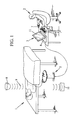
- a patient 1 is subjected to arteriography.
- This arteriography is performed by a staff 2, such as for example a surgeon, or qualified medical personnel, using an automated arteriography system 3 which comprises for example a programmable machine 4 remotely controlling a reel / unwinder 5 to catheters disposed near the patient 1.
- the reel / unwinder 5 is robotic and is sometimes also called "the robot".
- a catheter 6 inside the body of the patient 1 is controlled remotely by the qualified personnel 2 with the aid of a control means 7 such as for example a mouse or a joystick, connected to the machine programmable 4.
- a control means 7 such as for example a mouse or a joystick, connected to the machine programmable 4.
- the installation further comprises an x-ray source 8 emitting X-rays 9 to the patient 1, and an X-ray detector 10 capable of detecting radiation passing through the patient 1.
- the detector 10 can be connected to the computer 4 to display on the screen 11 thereof a detected image.
- the robot 5 comprises a vertical foot 38, a horizontal plate 39 carried by this foot, and at least a first concentric system 12 and a second system 13 arranged around an axis, for example oriented vertically along Z.
- the first system 12 comprises a first receptacle 14 in the form of a flexible tube carried by the plate at its periphery, for example clipping in hooks carried by the plate.
- the flexible tube extends from a first end 14a to a second end 14b making less than one turn of the tray.
- the tube 14 receives a catheter tubular 6 intended to be introduced into an artery of the patient 1.
- the flexible tube 14 comprises a longitudinal slot 53 through which the catheter 6 can enter or leave the tube 14.
- the flexible tube 14 could be replaced by a rigid tube provided with a lip for the entry / exit of the catheter.
- a rigid guide tube 106 extends between the longitudinal slot 53 and the drive mechanism 16. It receives the catheter 6 in its interior.
- the length of the tube 14 is greater than the conventional length of a catheter.
- the first system 12 also comprises a drive mechanism 16, or "module", which will be described in more detail later in connection with the Figures 3 to 6 .
- This drive mechanism is carried by an arm 15 fixedly connected to the foot, and is intended to be placed in the immediate vicinity of the patient's catheterization port. The position of the arm 15, particularly its height relative to the ground, may be adjusted if necessary for the purposes of the operation.
- the drive mechanism is controlled by the surgeon 2 via the computer 4.
- the second system 13 comprises a second receptacle 17, intended to be received fixed on the plate 39.
- the second system also comprises an outlet 18 through which a guide 37 contained in the second receptacle can access the outside of the second receptacle, and particularly within the first container 14. In particular, it accesses the inside of the catheter included in the first container.
- the second container receives a tubular guide 37 extending between a first and a second end along a guide elongation direction, and bathed in a suitable liquid for its preservation.
- second container also comprises a drive mechanism 19, similar to the first drive mechanism 16 of the first system 12, which will be described later in more detail in connection with the Figures 3 to 6 .
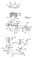
- the Figures 3 to 8 represent the first drive mechanism 16 according to an illustrative embodiment.
- the second drive mechanism 19 can be made in a similar manner.
- the first drive mechanism 16 comprises a base 43 fixed on the arm 15.
- the arm 15 carries a fixing support plate 42 pierced with two fixing holes, and two motorization holes
- the base 43 has a plate pierced with corresponding holes: fixing holes 41 and motor holes 50 placed opposite the holes of the plate 42.
- a sterility barrier 44 extends between the plate 42 associated with the arm 15 and the base 43, being pierced only to pass through these openings the fasteners 45 associated with the mounting holes, and the motor shafts associated with the motorization holes 50.
- the sterility barrier 44 will cover the arm 15, and in particular the motors 24. and 26, with the exception of base 43 and what it is wearing.
- the base 43 carries a mobile assembly 40 rotatably mounted relative to the base 43 around an axis of rotation coinciding with the axis X of elongation of the catheter 6 in two bearings 20a, 20b of the base.
- the base 43 has a U-shaped profile, where the two parallel arms of the U 46a, 46b are used to define the bearings.
- the arm 46b has an upwardly open slit 47 defining a bearing portion, and reclosable to complete the bearing by a removable device 48 such as a pin. Part of the pin and the slot together define the bearing.
- a removable device 48 such as a pin. Part of the pin and the slot together define the bearing.
- a similar embodiment is provided on the other arm.
- the mobile equipment comprises, in the example presented, a plate 21 which will be described in more detail later, carrying the catheter, a cylindrical rotating gear ring 23 mounted on an upstream cylindrical shaft 49, extending along the X axis, and a translational gear ring. mounted on a downstream cylindrical shaft 149, extending along the axis X, within which the catheter 6 passes.
- the upstream 49 and downstream 149 aligned trees define the drive shaft in translation and in rotation of the catheter.
- the first drive mechanism 16 comprises an electric rotation motor 24 ( figure 2 ) for driving the rotation of the catheter about the axis X.
- the motor 24 drives in rotation, during the passage of an electric current, on the control from the computer 4, the rotation of a rotation shaft 51 bearing rotating gear 25 which cooperates with the rotating gear ring 23 of the moving gear.
- the gears 25 and 23 have inclined teeth so that the rotation of the gear 25 about an axis transverse to the X axis can generate the rotation of the gear 23 about the X axis.
- the drive mechanism 16 also comprises an electric translation motor 26 ( figure 2 ) for driving the translation of the catheter along the axis X.
- the motor 26 drives in rotation, under the effect of the passage of the electric current, under the control of the computer 4, a translation shaft 52 carrying a gear of translation 27.
- the translation and rotation shafts 51 and 52 are parallel.
- a transfer sleeve 154 extends along the axis X and shifted axially along a translation gear 22 and an intermediate gear 30.
- the gears 27 and 22 have inclined teeth for the rotation of the gear 27 around an axis transverse to the axis X can generate the rotation of the gear 22 around the axis X.
- These motors are, for example, stepper or brushless motors.
- the translational gear ring 22 rotates a shaft 28, rotatably mounted in two bearings 29 internal to the wafer 21 via an intermediate gear 30.
- the shaft 28 carries a first and a second toothed surface 28a. , 28b.
- the shaft 28 could possibly be replaced by a worm.
- the wafer 21 has a bottom portion 54 adapted to receive various elements.
- cylindrical holes 56a-56d extending parallel to each other, in a direction transverse to the direction X, and arranged on each side of the axis X. It will be noted that the cylindrical holes 56a and 56d opposite diagonally open into the cylindrical hole 55 through a respective opening 57.
- Each of the holes 56a-56d receives a corresponding shaft 58a-58d.
- the shafts 58a and 58d are identical to each other and comprise, at the opening 57, a toothed wheel adapted to cooperate with the corresponding toothed bearing surface of the shaft 28, so that a rotation of the shaft 28 around its axis causes a rotation of the respective shaft 58a or 58d about its axis.
- Each of the shafts 58a-58d also carries a respective pulley 31a-31d.
- the pulley 31d comprises two superimposed disks 76a, 76b, along the shaft, between which extends a driving surface 77 of the belt 60b.
- the discs serve as upper and lower stops on the belt.
- the same description applies for all pulleys.
- the belt 60b has an inner face 78 toothed, cooperating with the drive surface 77, and an outer face 78b opposite.
- the outer face 78b is intended to cooperate with the catheter. It is made of a suitable material, which can undergo the deformations applied to the belt during the motorization, and remaining attached to the catheter, even when wet.
- a suitable elastomer, rubber or silicone is used.
- a channel 59 is defined between these four pulleys, and can receive a catheter.
- the two pulleys 31a and 31b are associated with each other in that a belt 60a is stretched between these two pulleys.
- a belt 60b is stretched between the two pulleys 31c and 31d.
- each belt includes a band portion 61a and 61b extending in the channel, and engaged with the catheter passing through the channel.
- the strip portions are elongated along the longitudinal direction, and run in this direction when the translation motor is actuated.
- An adjustment mechanism 34 makes it possible to adjust the use of the module to the elongated flexible member to be driven.
- the adjustment mechanism 34 may be used to finely adjust the drive system for different identical catheters, or to greatly modify the width of the channel in the case where the module is to be adapted for driving a catheter or a catheter. a guide, of much smaller diameter.
- the adjustment mechanism 34 comprises a longitudinal slide 62 formed in the bottom portion 54 of the wafer 21, and extending transversely to the longitudinal direction X, and a pusher 63 adapted to slide in this slideway 62. towards or away from the canal.
- the pusher 63 is disposed inside the periphery of the respective belt 60a or 60b, and has a tensioning surface 81 which cooperates with the inner face 78a of the belt so as to move the band portion 61a or 61b of the belt transversely to the direction X.
- the attachment of the pusher 63 in the set position can be done by any means suitable, in particular by a screw 64 screwed into a bore 65 formed in the bottom portion 54.
- the pusher has a length (along the axis of the slide) greater than the diameter of the pulleys. Thus, regardless of the position of the pusher relative to the belt in the adjustment range, the tension of the belts remains substantially the same.
- the belts have an inner surface 78a adapted to be driven by the driving pulley, and to slide along the surfaces cooperating with it, the pusher 63.
- Such an inner surface is for example toothed.
- the outer surface 78b of the belt is made of a material adapted to cooperate with the elongated medical device, flexible and wet and for example may comprise a suitable elastomeric material.
- a cover 66 is assembled to the bottom portion 54 of the wafer 21, to maintain the various parts that have just been described in the wafer.
- the shafts 58a and 58d are driven and are driven during the rotation of the shaft 28, so that the band portions 61a and 61b move at the channel in the same direction, for a given rotation of the drive motor in translation.
- these band portions directly apply the movement to the elongated flexible member.
- the shafts 58b, 58c are driven, and are not driven directly by the drive motors, but by the belts.
- the outlet 18 of the second system comprises a fixing device 35 allowing the free rotation of the catheter 6 around its axis of elongation relative to the second system, and driving the second container 17 during the translation of the catheter 6 along its direction of elongation.
- the fixation device 35 the distal end of the catheter 6 is fixed on a ring having a groove which fits into a complementary orifice formed in the second container. The ring is thus free to rotate relative to the second container about an axis of elongation of the guide 37.
- the ring may have a flared shape towards the catheter 6, to facilitate manual gripping by a user.
- the flap could be replaced by an open ring attached to the second container.
- the embodiment presented on the figure 2 can for example be made modular, namely that the first system 12 and the second system 13 can be marketed separately and assembled for the purpose of the examination of the patient.
- a third system that can be inserted in the second system and concentric about the Z axis with the latter, for insertion into the patient of an interventional catheter, in addition to the guide and the catheter, can be provided.
- the third system comprises a container that can contain a liquid, a drive mechanism and an outlet opening into the second system.
- the systems are arranged so that the insert with the largest diameter (usually the catheter) is placed in the external system, and the insertion element having the finest diameter (usually the guide) is placed in the system. the interventional catheter is therefore placed in the intermediate system.
- each system can itself be realized in a modular way, namely that the electric motors can be permanently supplied on the robot, and the rest of the system can be removed to be replaced by a consumable part without any electric motor.
- the costs associated with the reuse of the system are greatly reduced, since the most expensive elements can be kept from one use to another (these can possibly be sterilized or decontaminated before their subsequent use).
- a second sterile barrier 144 independent of the first can be slid between the plate 42 and the corresponding module.
- the second sterile barrier 144 will cover the motors 24 and 26 of the second system and the plate 39.
- the tube 14 and the container 17 will be placed above.
- the system allows simple and inexpensive repeated use.
- a major part of the system is disposed away from a sterile barrier, as explained above, and thus does not require complex and expensive repeat sterilization operations.
- the reduced part of the system intended to be in contact with the patient via an elongated medical flexible tubular member it consists exclusively of consumable parts, sterilizable parts, and quick assembly parts, they themselves sterilizable.
- the belts are made as consumable parts.
- the assembly parts it is possible, for example, to provide elastically deformable parts which hold together the sterilizable parts, where appropriate with possibility of movement relative to each other.
- U-shaped pins 67 have their two parallel arms inserted in corresponding openings 68 formed in the cylinders 69 for retaining the rotation or translation shafts 51, 52. These shafts each have a groove 70 which cooperates with each arm of the corresponding spindle 67 to prevent displacement of the shaft relative to the cylinder along its extension direction, while allowing its rotation.
- a pin 71 similar is provided to cooperate with a groove 72 formed in the shaft 28, to prevent the output of the shaft 28 out of its receiving cylinder.
- Similar systems may be provided to hold the cover 66 on the bottom portion 54 of the moving assembly.
- the bottom portion 54 may comprise, on the upper surface, four pins 73.
- the cover 66 is inserted on these pins via corresponding openings 74 arranged at each corner.
- the pins 73 are themselves provided with through openings 75 aligned in pairs, adapted to receive an arm of a pin (not shown) similar to the pins 48 described above.
- Fixing the base 43 on its support can be done in a similar manner, by retaining pins of the support passing through the bores 41 of the base 43 with deformable elastic retention means.
- the assembly parts and the assembled parts are so-called “sterilizable” parts in that they are easy to clean in their entirety, without presenting a nook or area inaccessible to cleaning.
- figure 2 An example of use of the device shown in the figures is described below. It should be noted that figure 2 , almost the entire catheter has entered the patient's interior. A surgeon punctures an artery, for example the femoral artery at the inguinal fold and puts in place a short pipe with a valve providing an access door between the outside and the artery, commonly called a device. The winder / unwinder of the figure 2 is placed near the patient, and is connected to the computer 4. The reel / unwinder 5 already contains a preserving liquid in which is bathed in the first system, a catheter, and in the second system a guide insertable in the catheter.
- a preserving liquid in which is bathed in the first system, a catheter, and in the second system a guide insertable in the catheter.
- the catheter By opening up the adjustment mechanism 34 of the first system as much as possible, the catheter can be moved to be manually inserted by the surgeon through the desilter into the artery. Then, from the computer 4, the surgeon controls the translational motor of the second system to guide the guide 37, through the outlet 18, inside the catheter 6, until the first end of the guide arrives. inside the patient at the first end of the catheter. During this operation, the X-ray source 8 can emit radiation which has no influence on the surgeon 2, and the image by the detector 10 can be displayed on the screen 11 of the computer.
- Fig. 11a represents a starting position in the repository of the part. If only the rotation motor is controlled, the moving assembly 40 will rotate about the X axis as shown. Due to the meshing between the gears 30 and 28, if the toothed wheel 30 is held stationary (ie the translation motor is not controlled), the toothed wheel 28 will also turn around its axis. This is illustrated in Fig. 11b by a reference arrow indicating a reference tooth of the gear 28.
- the rotation control generates a rotation of the shaft 28 in the reference frame of the moving equipment, and therefore a rotation of the belts (a translation of the catheter).
- the commands of both translation and rotation can of course be made in one direction or the other, to move the guide and the catheter to the site, where to bring back.
- Rotation of the second container relative to the first container can be achieved by rotating the plate 39 by a specially dedicated electric motor 75 connected under the plate.
- This dedicated engine can in particular be used to guide the tray after use.
- the figure 7a is a top view of the system in a position where the catheter has almost fully entered the patient's body.
- the rotation of the plate 39 causes the guide to be translated by report to the patient, if the second drive system is inactive during this step. If it is desired on the contrary that the guide remains stationary in the patient during this step, the translation motor of the guide is commanded to translate it relative to the second system, in a predetermined ratio with the command in translation of the catheter.
- the geared motors are equipped with pulse encoders giving the displacements. These movements are measured by any appropriate means.
- the translation motors of the two drive systems and the plateau motor are controlled in predetermined ratios.
- the consumable elements can be discarded, and the various non-consumable elements are parts of small dimensions and simple shapes, which can be sterilized.
- the consumable parts of the robot such as the tube 14 containing the catheter removed from the patient's body, or the connecting device 35 can also be disassembled and discarded or sterilized as appropriate and the sterile barriers are discarded.
- the assembly of the system can be done, by a sterile operator, by a series of reverse operations of the sequence of operations described above for disassembly.
- the adjustment system 34 may be made in any suitable manner, such as a mechanical system using screws 64 or, alternatively, a piezoelectric system or the like.
- FIG. 10a Another variant embodiment is represented on the figure 10a .
- Two end pins 87 are used to assemble the bottom portion 54 to the consumable portion 80, and a cover portion 88 is assembled to the consumable portion 80 in a similar manner, using two end pins 87 '.
- the portion 80 is therefore maintained between the bottom portion 54 and the cover portion 88.
- the cover portion 88 may also include the adjustment system 34 pushers. So unlike the embodiment of the Fig. 10 where the driving zone 89 of the pushers by the screw 64 (not shown) is located under the body 97 of the pusher, in the Fig. 10a this zone 89 is placed on top of the pusher body, so as to interact with the screw 64 mounted in the cover 88.
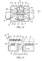
- the axis around which the moving element rotates relative to the base, and the median axis of the catheter where it is driven by the belts, are merged, and parallel to the longitudinal direction X.
- the axis of rotation X1 and the translation drive axis X2 are shown offset with respect to each other in a direction transverse to the longitudinal direction.
- the translation drive axis X2 is defined as the median axis between the two drive surfaces 77 in use, which are themselves defined by the surfaces of the belts.
- the position of the axis 52 in use is therefore defined by the position of the pushers 63. That is to say that the channel comprises a central portion 85 extending along the axis X2 and input portions 86a and output 86b forming a non-zero angle with the longitudinal direction.
- a lateralization system 96 which defines the position of the axis X2 relative to the axis of rotation X1.
- the value of the offset between the two axes can therefore be adjustable.
- the pushers 63 are not only used to define the width of the channel, the clamping force applied to the catheter, or the tension of the belts, but also the offset of the axes X1 and X2.
- the lower pusher 63 has an inner portion 63a and an outer portion 63b can be fixed in a plurality of distinct positions along the transverse axis relative to the inner portion 63a. This adjustment adjusts the tension of the lower belt.
- the upper pusher 63 has an inner portion 63'a similar to the inner portion 63a and an outer portion 63'b.
- the outer portion 63'b here is independent of the inner portion 63'a, and made for example in the form of two tensioning rollers. If necessary, these can be provided movable so that their displacement along the transverse axis allows to adjust the tension of the belt.
- the displacement of the two inner portions in opposite directions makes it possible on the one hand to adapt the system to the width of the member to be driven, and on the other hand to adjust the clamping force applied to this member. Moving the two inner portions in the same direction allows you to adjust the axis offset.
- this axis offset makes it possible to obtain the displacement desired rotation of the end of the catheter within the patient.
- the axis offset can be varied during the use of the robot.
- motorization devices 82 remotely controlled by the user, to move each pusher in the desired position.
- An exemplary embodiment comprises a geared motor 83 driving an endless screw 84 rotating in a nut fixed to each pusher.
- Other variants than that shown are possible, such as having the two geared motors located on the same side of the channel, and / or using a jack or a micro-positioner.
- one can bind the two mechanisms, so as to have a command for the position of the axis X2, and another command for the spacing pushers relative to this axis (width of the catheter and clamping thereof).
- the axis offset could alternatively be implemented for other types of translation drive system on board a rotary plate, such as in particular a system having one or more roller (s) of drive having a non-extended driving surface.
- a single lateralization system 96 is used to firstly grip the catheter with a predetermined force (for example 6 Newtons) and then, when the actuation of the system control is continued, shift the drive shaft X2 with respect to the axis of rotation X1.
- a predetermined force for example 6 Newtons
- a second spring 93 (or any other suitable elastic element) extending between a first end 90a urging a first pusher 63, and a second end 90b urging a slider 91.
- the slider itself is mounted movably along the transverse axis of displacement of the pusher, for example by means of the screw 64.
- the spring 90 is also carried by a rod 92 having a stop end 92a.
- a second spring 93 (or any other suitable elastic element) is provided between the frame 94 and the second pusher 63 '.
- the second pusher 63 ' is provided with an abutment surface 95 facing the abutment surface 92a of the stem.
- the actuation of the screw 64 generates the translation of the slider 91 and thus the displacement of the first pusher 63 until the abutment end 92a of the rod comes into abutment on the abutment 95. In this position, the catheter is subjected to the predetermined clamping force, according to the compression of the spring 90. Continued actuation of the screw 64 will cause the compression of the spring 93, and therefore the movement of the first and second pushers towards the frame. Thus, continuing the actuation of the screw 64 will cause the shift axis X2.
- the screw 64 can be driven manually, or motorized, for example by a motor powered by battery, or mechanically remotely by an actuator, in a predetermined position of the module (called adjustment position), where the The actuator is in a position suitable for carrying out this training.
- screw 64 As an alternative to the screw 64, other systems may be used, such as rack systems, for example.
Abstract
Description
La présente invention est relative aux modules et procédés d'entraînement d'organes médicaux souples allongés, et aux systèmes robotisés associés.The present invention relates to modules and methods for training elongated soft medical organs, and associated robotic systems.
Plus particulièrement, l'invention se rapporte à un module d'entraînement d'un organe médical souple allongé selon une première direction, comprenant une base et un équipage mobile monté rotatif sur ladite base autour de la première direction, l'équipage mobile comportant un support.More particularly, the invention relates to a drive module of a flexible medical organ elongate in a first direction, comprising a base and a movable assembly rotatably mounted on said base around the first direction, the movable element comprising a support.
Un exemple typique d'organe médical souple allongé est par exemple un cathéter. Un tel cathéter doit être introduit dans un conduit anatomique d'un patient, et doit donc être relativement souple. L'extrémité du cathéter doit aussi parvenir jusqu'à un organe interne du patient, il doit donc être relativement allongé. D'autres exemples d'organes médicaux souples allongés sont par exemple un guide, qui est de diamètre inférieur, et généralement disposé à l'intérieur du cathéter et sur lequel ce dernier glisse, ou un cathéter interventionnel, également disposé à l'intérieur du cathéter, et dont l'extrémité fournit une certaine fonction médicale telle qu'un outil médical (pince, ballon, etc...).A typical example of an elongated flexible medical organ is, for example, a catheter. Such a catheter must be introduced into an anatomical conduit of a patient, and must therefore be relatively flexible. The tip of the catheter must also reach an internal organ of the patient, so it must be relatively elongated. Other examples of elongated soft medical devices are for example a guide, which is of smaller diameter, and generally disposed within the catheter and on which the latter slides, or an interventional catheter, also disposed within the catheter, and whose end provides a certain medical function such as a medical tool (clamp, balloon, etc ...).
L'insertion de tels cathéters est généralement monitorée sous rayons X. Il en découle une irradiation certaine du médecin pratiquant de manière répétée de telles insertions.The insertion of such catheters is generally monitored under X-rays. This results in certain irradiation of the doctor repeatedly practicing such insertions.
Des efforts ont été faits pour robotiser cette insertion. Ainsi, la manipulation du cathéter est assurée par le robot, qui est commandé à distance par le médecin, toujours sous guidage aux rayons X, mais dans une pièce non irradiée.Efforts have been made to robotize this insertion. Thus, the manipulation of the catheter is provided by the robot, which is controlled remotely by the doctor, still under X-ray guidance, but in a non-irradiated room.
Le document
Ce système présente le grand avantage d'être bien adapté au caractère stérile des cathéters ou autres organes introduits dans le patient, qui baignent dans un liquide de conservation tel que du sérum physiologique. Toutefois, dans ce document, le cathéter est entrainé, au niveau du module d'entraînement par 2 roues disposées d'un même côté, une troisième roue, non-entrainée, disposée de l'autre côté du cathéter servant à maintenir la pression.This system has the great advantage of being well adapted to the sterility of catheters or other organs introduced into the patient, which bathe in a preservative liquid such as saline. However, in this document, the catheter is driven, at the level of the drive module by 2 wheels arranged on the same side, a third wheel, untrained, disposed on the other side of the catheter used to maintain the pressure.
En pratique, il a été observé des problèmes d'entraînement du cathéter avec un tel mécanisme. Ces problèmes sont notamment dus d'une part à la souplesse du cathéter, et d'autre part à sa conservation en milieu liquide.In practice, catheter drive problems with such a mechanism have been observed. These problems are due on the one hand to the flexibility of the catheter, and on the other hand to its preservation in a liquid medium.
La présente invention a notamment pour but de pallier ces inconvénients.The present invention is intended to overcome these disadvantages.
A cet effet, selon l'invention, un module d'entraînement du genre en question est caractérisé en ce que le module comprend :
- un canal défini dans le support, et s'étendant selon la première direction,
- de chaque côté du canal :
- . au moins une première et une deuxième poulies comportant une surface d'entraînement, et portées par le support,
- . une bande allongée comprenant une première face et une deuxième face opposée, la première face coopérant avec la surface d'entraînement des poulies, la deuxième face adaptée pour coopérer avec l'organe médical souple, la bande étant tendue par les poulies avec une portion allongée s'étendant dans le canal selon la première direction,
- a channel defined in the support, and extending in the first direction,
- on each side of the canal:
- . at least first and second pulleys having a driving surface and carried by the support,
- . an elongated strip comprising a first face and a second opposite face, the first face cooperating with the driving surface of the pulleys, the second face adapted to cooperate with the flexible medical organ, the band being stretched by the pulleys with an elongated portion extending in the channel in the first direction,
Grâce à ces dispositions, on optimise la linéarité du cathéter au niveau du module d'entraînement, ce qui permet d'améliorer son entraînement.Thanks to these provisions, optimizes the linearity of the catheter at the drive module, which improves its training.
Dans des modes de réalisation préférés de l'invention, on peut éventuellement avoir recours en outre à l'une et/ou à l'autre des dispositions suivante :
- le module comprend en outre un dispositif de réglage placé entre la première et la deuxième poulie, une surface tendeuse coopérant avec la première face de la bande, et mobile par rapport au canal le long d'une direction d'ajustement transverse à la première direction ;
- la première face de la bande présente des dents d'entraînement et la surface d'entraînement de la poulie motorisée présente des dents complémentaires auxdites dents d'entraînement ;
- le module comprend un ensemble de pièces d'entrainement coopérant entre elles pour transmettre un mouvement d'un moteur à la poulie motorisée ;
- l'équipage mobile est monté rotatif sur la base autour d'un premier axe, et le canal comprend une portion définie dans le support selon un deuxième axe, parallèle au premier axe et décalé par rapport à celui-ci ;
- le module comprend un dispositif de latéralisation adapté pour régler un décalage du premier et du deuxième axe ;
- le dispositif de latéralisation comporte une commande adaptée pour, lors d'une première partie de course d'entraînement, causer un enserrement de l'organe médical, et lors d'une deuxième partie de course d'entraînement suivant la première partie, régler ledit décalage du premier et du deuxième axe ;
- le module est constitué desdites bandes, de pièces stérilisables, et de pièces d'assemblage amovibles à déformation élastique adaptées pour maintenir ensemble les pièces stérilisables avec liberté de mouvement les unes par rapport aux autres.
- the module further comprises an adjusting device placed between the first and second pulley, a tensioning surface cooperating with the first face of the strip, and movable with respect to the channel along a direction of transverse adjustment to the first direction ;
- the first face of the belt has drive teeth and the drive surface of the motorized pulley has teeth complementary to said drive teeth;
- the module comprises a set of driving parts cooperating with each other to transmit a movement of an engine to the motorized pulley;
- the moving element is rotatably mounted on the base around a first axis, and the channel comprises a portion defined in the support along a second axis, parallel to the first axis and offset relative thereto;
- the module comprises a lateralization device adapted to adjust an offset of the first and second axis;
- the lateralization device comprises a control adapted to, during a first part of the training stroke, cause a grip of the medical organ, and during a second part of the training stroke according to the first part, adjusting said offset of the first and second axes;
- the module consists of said strips, sterilizable parts, and removable elastic deformation assembly parts adapted to hold together the sterilizable parts with freedom of movement relative to each other.
Selon un autre aspect, l'invention se rapporte à un système robotisé qui comprend :
- un tel module d'entraînement,
- un récipient adapté pour contenir un organe médical souple allongé en condition aqueuse stérile, et en communication avec ledit canal,
- un moteur coopérant avec la poulie motorisée.
- such a training module,
- a container adapted to contain an elongated flexible medical organ in sterile aqueous condition, and in communication with said channel,
- a motor cooperating with the motorized pulley.
Selon un mode de réalisation, le système comprend en outre une barrière stérile, le moteur coopérant avec la poulie motorisée à travers la barrière stérile.According to one embodiment, the system further comprises a sterile barrier, the motor cooperating with the motorized pulley through the sterile barrier.
Selon un autre aspect, on prévoit un procédé d'entraînement d'un organe médical souple allongé selon une première direction, qui comprend :
- on fournit un module d'entraînement comprenant :
- . un canal s'étendant selon la première direction,
- . de chaque côté du canal :
- .. au moins une première et une deuxième poulies comportant une surface d'entraînement,
- .. une bande allongée comprenant une première face et une deuxième face opposée, la première face coopérant avec la surface d'entraînement des poulies, la deuxième face adaptée pour coopérer avec l'organe médical souple, la bande étant tendue par les poulies avec une portion allongée s'étendant dans le canal selon la première direction,
- on place un organe médical souple allongé selon la première direction partiellement dans ledit canal,
- on motorise au moins une des poulies.
- a training module is provided comprising:
- . a channel extending in the first direction,
- . on each side of the canal:
- at least first and second pulleys having a driving surface,
- an elongated strip comprising a first face and a second opposite face, the first face cooperating with the drive surface of the pulleys, the second face adapted to cooperate with the flexible medical device, the band being stretched by the pulleys with a an elongate portion extending in the channel in the first direction,
- an elongated flexible medical organ is placed according to the first direction partially in said channel,
- at least one of the pulleys is motorized.
Selon un autre aspect, l'invention se rapporte à un système d'artériographie robotisé comprenant :
- une base munie d'un premier organe de transmission,
- un module d'entraînement d'un organe médical flexible allongé selon une direction d'extension comprenant :
- . un deuxième organe de transmission adapté pour coopérer avec le premier organe de transmission,
- . au moins un organe d'entraînement raccordé au deuxième organe de transmission, et adapté pour coopérer avec un organe médical flexible allongé pour alternativement maintenir ledit organe médical fixe par rapport à la base ou translater ledit organe médical selon la direction d'extension,
- une barrière de stérilité recouvrant la base, les premier et deuxième organes de transmissions coopérant à travers la barrière de stérilité,
- a base provided with a first transmission member,
- a drive module of a flexible medical organ elongate in an extension direction comprising:
- . a second transmission member adapted to cooperate with the first transmission member,
- . at least one drive member connected to the second transmission member, and adapted to cooperate with an elongated flexible medical device for alternately holding said medical device fixed relative to the base or translating said medical device in the direction of extension,
- a sterility barrier covering the base, the first and second transmission members cooperating through the sterility barrier,
Selon un autre aspect, une invention se rapporte à un système de cathétérisme robotisé comprenant :
- une unité centrale,
- au moins une première, une deuxième et une troisième lignes de commande adaptées respectivement pour envoyer une commande à un premier, un deuxième et un troisième moteurs d'entraînement d'un même cathéter,
- dans lequel les première et deuxième lignes de commande sont commandées selon un premier rapport prédéfini pour commander un mouvement de translation pure du cathéter le long de son axe, et dans lequel les première et troisième lignes de commande sont commandées selon un deuxième rapport prédéfini pour commander un mouvement de rotation pure du cathéter le long de son axe.
- a central unit,
- at least first, second and third control lines respectively adapted to send a command to a first, a second and a third drive motors of the same catheter,
- wherein the first and second command lines are controlled according to a first predefined report for controlling a pure translational movement of the catheter along its axis, and wherein the first and third control lines are controlled in a second predefined ratio for controlling a pure rotational movement of the catheter along its axis.
Selon un autre aspect, une invention se rapporte à un module d'entraînement comprenant une base et un équipage mobile monté rotatif sur ladite base autour de la première direction, dans lequel l'équipage mobile comprend :
- une partie de fond comprenant au moins un arbre d'entraînement, et
- une partie consommable dans laquelle ledit canal est défini, la partie consommable comprenant au moins lesdites poulies, la partie consommable étant assemblable sur la partie de fond, la poulie motorisée coopérant avec ledit arbre d'entraînement.
- a bottom portion comprising at least one drive shaft, and
- a consumable part in which said channel is defined, the consumable part comprising at least said pulleys, the consumable part being assembled on the bottom part, the motorized pulley cooperating with said drive shaft.
La partie consommable sera jetée après utilisation, et remplacée par une pièce identique pour une utilisation future.The consumable part will be discarded after use, and replaced with an identical part for future use.
Selon un autre aspect, une invention se rapporte à un module d'entraînement d'un organe médical souple allongé selon une première direction, comprenant une base et un équipage mobile monté rotatif sur ladite base autour d'un premier axe s'étendant selon la première direction, l'équipage mobile comportant un support,
dans lequel le module comprend :
- un canal défini dans le support, et s'étendant selon la première direction,
- de chaque côté du canal :
- . au moins un premier et un deuxième organe d'entraînement portés par le support, et présentant chacun une face adaptée pour coopérer avec l'organe médical souple,
wherein the module comprises:
- a channel defined in the support, and extending in the first direction,
- on each side of the canal:
- . at least a first and a second drive member carried by the support, and each having a face adapted to cooperate with the flexible medical organ,
En particulier, l'amplitude du décalage d'axe peut être variable.In particular, the amplitude of the axis shift can be variable.
D'autres caractéristiques et avantages de l'invention apparaîtront au cours de la description suivante de plusieurs formes de réalisation, donnée à titre d'exemple non limitatif, en regard des dessins joints.Other features and advantages of the invention will become apparent from the following description of several embodiments, given by way of non-limiting example, with reference to the accompanying drawings.
Sur les dessins :
- la
figure 1 est une vue schématique d'une installation d'artériographie robotisée, - la
figure 2 est une vue éclatée partielle en perspective d'un robot de cathéterisme, - la
figure 3 est une vue en perspective d'un module d'entraînement pour le robot de lafigure 2 , - la
figure 4 est une vue de dessus du module de lafigure 3 après ouverture du couvercle, - la
figure 5 est une vue éclatée en perspective de l'équipage mobile du module desfigures 3 et 4 , - la
figure 6 est une vue éclatée en perspective du module de lafigure 3 , et - les
figures 7a et 7b sont des vues de dessus du robot dans deux positions différentes, - la
figure 8 présente un agrandissement de lafigure 2 montrant l'emplacement d'une barrière stérile, - la
figure 9 est une vue en coupe selon la ligne IX-IX de lafigure 5 , - la
figure 10 est une vue schématique en perspective en éclaté d'un deuxième mode de réalisation de plaquette, - la
figure 10a est une vue similaire à lafigure 10 pour une variante de réalisation, - les
figures 11a, 11b et 11c illustrent divers états selon la commande appliquée aux différents moteurs, - la
figure 12 illustre un troisième mode de réalisation, et - la
figure 13 est une vue partielle schématique de face illustrant un quatrième mode de réalisation.
- the
figure 1 is a schematic view of a robotic arteriography facility, - the
figure 2 is a partial exploded view in perspective of a catheterization robot, - the
figure 3 is a perspective view of a drive module for the robot of thefigure 2 , - the
figure 4 is a top view of the module of thefigure 3 after opening the lid, - the
figure 5 is an exploded view in perspective of the mobilefigures 3 and4 , - the
figure 6 is an exploded view in perspective of the module of thefigure 3 , and - the
Figures 7a and 7b are top views of the robot in two different positions, - the
figure 8 presents an enlargement of thefigure 2 showing the location of a sterile barrier, - the
figure 9 is a sectional view along the line IX-IX of thefigure 5 , - the
figure 10 is an exploded perspective schematic view of a second embodiment of a wafer, - the
figure 10a is a view similar to thefigure 10 for an embodiment variant, - the
Figures 11a, 11b and 11c illustrate various states according to the command applied to the different engines, - the
figure 12 illustrates a third embodiment, and - the
figure 13 is a schematic partial front view illustrating a fourth embodiment.
Sur les différentes figures, les mêmes références désignent des éléments identiques ou similaires.In the different figures, the same references designate identical or similar elements.
Sur la
Le déplacement d'un cathéter 6 à l'intérieur du corps du patient 1 est commandé à distance par le personnel qualifié 2 à l'aide d'un moyen de commande 7 tel que par exemple une souris ou un joystick, reliée à la machine programmable 4.The displacement of a
L'installation comprend en outre une source de rayons X 8 émettant des rayons X 9 vers le patient 1, et un détecteur de rayons X 10 apte à détecter le rayonnement traversant le patient 1. Le détecteur 10 peut être relié à l'ordinateur 4 pour afficher sur l'écran 11 de celui-ci une image détectée.The installation further comprises an
Comme représenté sur la
Le premier système 12 comporte un premier récipient 14 en forme de tube souple porté par le plateau à sa périphérie, par exemple clipsable dans des crochets portés par le plateau. Le tube souple s'étend d'une première extrémité 14a à une deuxième extrémité 14b faisant moins d'un tour du plateau. Le tube 14 reçoit un cathéter tubulaire 6 destiné à être introduit dans une artère du patient 1. Le tube souple 14 comprend une fente longitudinale 53 par laquelle le cathéter 6 peut entrer ou sortir du tube 14. Le tube 14 souple pourrait être remplacé par un tube rigide muni d'une lèvre pour l'entrée/la sortie du cathéter. Un tube de guidage rigide 106 s'étend entre la fente longitudinale 53 et le mécanisme d'entraînement 16. Il reçoit le cathéter 6 en son intérieur. La longueur du tube 14 est supérieure à la longueur classique d'un cathéter. Ce cathéter s'étend d'une première extrémité à une deuxième extrémité le long d'une direction d'élongation de cathéter. Le tube 14 est par ailleurs rempli d'un liquide de conservation dans lequel baigne le cathéter. Le premier système 12 comporte également un mécanisme d'entraînement 16, ou « module », qui sera décrit plus en détail par la suite en relation avec les
Le deuxième système 13 comporte un deuxième récipient 17, destiné à être reçu fixé sur le plateau 39. Le deuxième système comporte également une sortie 18 par laquelle un guide 37 contenu dans le deuxième récipient peut accéder à l'extérieur du deuxième récipient, et en particulier à l'intérieur du premier récipient 14. En particulier, il accède à l'intérieur du cathéter compris dans le premier récipient.The
Le deuxième récipient reçoit un guide tubulaire 37 s'étendant entre une première et une deuxième extrémité le long d'une direction d'élongation de guide, et baignant dans un liquide adapté à sa conservation. Par ailleurs, le deuxième récipient comporte également un mécanisme d'entraînement 19, similaire au premier mécanisme d'entraînement 16 du premier système 12, et qui sera décrit par la suite plus en détail en relation avec les
Les
Le premier mécanisme d'entraînement 16 comporte un moteur électrique de rotation 24 (
Le mécanisme d'entraînement 16 comporte également un moteur électrique de translation 26 (
Ces moteurs sont par exemple des moteurs pas à pas ou brushless.These motors are, for example, stepper or brushless motors.
La bague d'engrenage de translation 22 entraîne en rotation un arbre 28, monté rotatif dans deux paliers 29 internes à la plaquette 21 par l'intermédiaire d'un engrenage intermédiaire 30. L'arbre 28 porte une première et une deuxième portée dentée 28a, 28b. L'arbre 28 pourrait éventuellement être remplacé par une vis sans fin.The
Comme cela est visible sur la
Dans la plaquette sont ménagés quatre trous cylindriques 56a-56d s'étendant parallèlement les uns aux autres, dans une direction transversale à la direction X, et disposés de chaque côté de l'axe X. On notera que les trous cylindriques 56a et 56d opposés diagonalement débouchent dans le trou cylindrique 55 par le biais d'une ouverture respective 57.In the plate are formed four
Chacun des trous 56a-56d reçoit un arbre correspondant 58a-58d. Les arbres 58a et 58d sont identiques entre eux et comportent, au niveau de l'ouverture 57, une roue dentée adaptée pour coopérer avec la portée dentée correspondante de l'arbre 28, de sorte qu'une rotation de l'arbre 28 autour de son axe entraîne une rotation de l'arbre 58a ou 58d respectif autour de son axe.Each of the
Chacun des arbres 58a-58d porte également une poulie 31a-31d respective. Comme visible sur la
Dans une position donnée du module d'entraînement, chaque courroie comprend une portion de bande 61a et 61b s'étendant dans le canal, et en prise avec le cathéter passant dans le canal. Les parties de bandes sont allongées le long de la direction longitudinale, et courent dans cette direction en cas d'actionnement du moteur de translation.In a given position of the drive module, each belt includes a
Un mécanisme de réglage 34 permet de régler l'utilisation du module à l'organe souple allongé à entrainer. Ainsi, le mécanisme de réglage 34 peut être utilisé pour régler finement le système d'entraînement pour différents cathéters identiques, ou pour modifier largement la largeur du canal dans le cas où le module doit être adapté pour l'entraînement d'un cathéter ou d'un guide, de diamètre largement inférieur. Dans l'exemple présenté, le mécanisme de réglage 34 comprend une glissière longitudinale 62 formée dans la partie de fond 54 de la plaquette 21, et s'étendant transversalement à la direction longitudinale X, et un poussoir 63 adapté pour coulisser dans cette glissière 62 en direction de ou en s'éloignant du canal. Le poussoir 63 est disposé à l'intérieur de la périphérie de la courroie respective 60a ou 60b, et présente une surface tendeuse 81 qui coopère avec la face interne 78a de la courroie de manière à déplacer la partie de bande 61a ou 61b de la courroie transversalement à la direction X. La fixation du poussoir 63 dans la position réglée peut se faire par tout moyen approprié, notamment par une vis 64 vissée dans un alésage 65 ménagé dans la partie de fond 54. Le poussoir présente une longueur (selon l'axe de la glissière) supérieure au diamètre des poulies. Ainsi, quelle que soit la position du poussoir par rapport à la courroie dans la gamme de réglage, la tension des courroies reste sensiblement la même.An
Les courroies présentent une surface interne 78a adaptée pour être entraînée par la poulie motrice, et pour glisser le long des surfaces, coopérant avec elle, du poussoir 63. Une telle surface interne est par exemple dentée. La surface externe 78b de la courroie est réalisée dans un matériau adapté pour coopérer avec l'organe médical allongé, souple et humide et par exemple peut comporter un matériau élastomère adapté.The belts have an
En cours d'utilisation, un couvercle 66 est assemblé à la partie de fond 54 de la plaquette 21, afin de maintenir les différentes parties qui viennent d'être décrites dans la plaquette. Dans le présent exemple de réalisation, les arbres 58a et 58d sont moteurs et sont, entraînés, lors de la rotation de l'arbre 28, de sorte que les parties de bande 61a et 61b se déplacent au niveau du canal dans une même direction, pour une rotation donnée du moteur d'entraînement en translation. Ainsi, ces parties de bande appliquent directement le mouvement à l'organe souple allongé. Les arbres 58b, 58c sont menés, et ne sont pas directement entraînés par les moteurs de translation, mais par les courroies.In use, a
Comme représenté sur la
Selon une variante, le volet pourrait être remplacé par un anneau ouvert rapporté sur le deuxième récipient.Alternatively, the flap could be replaced by an open ring attached to the second container.
On notera que le mode de réalisation présenté sur la
On peut d'ailleurs prévoir en outre, un troisième système insérable dans le deuxième système et concentrique autour de l'axe Z avec celui-ci, pour l'insertion dans le patient d'un cathéter interventionnel, en plus du guide et du cathéter. De manière similaire le troisième système comporte un récipient pouvant contenir un liquide, un mécanisme d'entraînement et une sortie débouchant dans le deuxième système. Les systèmes sont disposés de sorte que l'élément à insérer présentant le plus large diamètre (généralement le cathéter) est placé dans le système externe, et l'élément à insérer présentant le plus fin diamètre (généralement le guide) est placé dans le système interne, le cathéter interventionnel étant par conséquent placé dans le système intermédiaire.Furthermore, a third system that can be inserted in the second system and concentric about the Z axis with the latter, for insertion into the patient of an interventional catheter, in addition to the guide and the catheter, can be provided. . Similarly, the third system comprises a container that can contain a liquid, a drive mechanism and an outlet opening into the second system. The systems are arranged so that the insert with the largest diameter (usually the catheter) is placed in the external system, and the insertion element having the finest diameter (usually the guide) is placed in the system. the interventional catheter is therefore placed in the intermediate system.
En outre, chaque système peut lui-même être réalisé de manière modulaire, à savoir que les moteurs électriques peuvent être fournis à demeure sur le robot, et le reste du système peut en être démonté pour être remplacé par une pièce consommable sans aucun moteur électrique. De cette manière, on diminue grandement les coûts liés à la réutilisation du système, car on peut garder d'une utilisation à l'autre les éléments les plus coûteux (ceux-ci pouvant éventuellement être stérilisés ou décontaminés avant leur utilisation ultérieure).In addition, each system can itself be realized in a modular way, namely that the electric motors can be permanently supplied on the robot, and the rest of the system can be removed to be replaced by a consumable part without any electric motor. In this way, the costs associated with the reuse of the system are greatly reduced, since the most expensive elements can be kept from one use to another (these can possibly be sterilized or decontaminated before their subsequent use).
La description ci-dessus a été donnée par référence au premier système d'entraînement 12. Une description similaire est possible pour le deuxième mécanisme d'entraînement 19. De manière similaire à la première barrière stérile 44, une deuxième barrière stérile 144, indépendante de la première, peut être glissée entre la plaque 42 et le module correspondant. La deuxième barrière stérile 144 va recouvrir les moteurs 24 et 26 du deuxième système et le plateau 39. Par contre, le tube 14 et le récipient 17 vont être placés au-dessus.The above description has been given with reference to the
Dans un mode de réalisation particulier, comme représenté en particulier sur la
Une broche 71 similaire est prévue pour coopérer avec une gorge 72 ménagée dans l'arbre 28, afin d'empêcher la sortie de l'arbre 28 hors de son cylindre de réception.A
Des systèmes similaires peuvent être prévus pour maintenir le couvercle 66 sur la partie de fond 54 de l'équipage mobile. Ainsi la partie de fond 54 peut comporter, en surface supérieure, quatre pions 73. Le couvercle 66 est inséré sur ces pions par l'intermédiaire d'ouvertures 74 correspondantes disposées en chaque coin. Les pions 73 sont eux-mêmes pourvus d'ouvertures traversantes 75 alignées deux à deux, aptes à recevoir un bras d'une goupille (non représentée) similaire aux goupilles 48 décrites ci-dessus.Similar systems may be provided to hold the
La fixation de la base 43 sur son support peut se faire d'une manière similaire, en retenant des tétons du support passant à travers les alésages 41 de la base 43 avec des moyens de rétention élastiques déformables.Fixing the base 43 on its support can be done in a similar manner, by retaining pins of the support passing through the
Ainsi, les pièces d'assemblage et les pièces assemblées sont des pièces dites « stérilisables » en ce qu'elles sont nettoyables facilement en leur totalité, sans présenter de recoin ou de zone inaccessible au nettoyage.Thus, the assembly parts and the assembled parts are so-called "sterilizable" parts in that they are easy to clean in their entirety, without presenting a nook or area inaccessible to cleaning.
Un exemple d'utilisation du dispositif représenté sur les figures est décrit ci-après. Il est à noter qu'à la
Pour que l'extrémité du cathéter atteigne l'emplacement d'intérêt à l'intérieur du corps du patient 1, le chirurgien 2 commande, depuis l'ordinateur 4, les fonctions suivantes :
- translation du guide : par activation du moteur électrique de
translation 26 du deuxième système, qui entraîne en rotation un ensemble de pièces d'entraînement, notamment la bague d'engrenage 22 de translation,l'engrenage intermédiaire 30, l'arbre 28, les roues dentées 32a et 32b et de ce fait, les poulies d'entraînement 31a à 31d et donc les courroies60a et 60b qui génèrent une translation du guide le long de sa direction d'élongation à l'intérieur du cathéter 6, - la rotation du guide autour de l'axe longitudinal du guide, en commandant l'actionnement du moteur électrique de
rotation 24 du deuxième système, et par là un ensemble de pièces d'entraînement, notamment l'engrenage derotation 25 et la bague d'engrenage derotation 23 qui entraîne en rotation l'ensemble de l'équipage mobile et du guide par rapport auxpaliers 20a et60a et 60b, - la translation du cathéter le long de sa direction d'élongation de cathéter par la commande similaire à la commande de translation du guide décrit précédemment, (du fait de la liaison de la deuxième extrémité du cathéter au dispositif de
fixation 35, cette translation entraîne la rotation libre du deuxième système autour de l'axe Z par rapport au premier récipient), et - la rotation du cathéter, commandée comme décrit précédemment pour le guide, le dispositif de
fixation 35 autorisant le fait que le cathéter 6 tourne autour de son axe d'élongation sans influer sur leguide 37 ni le deuxième récipient.
- translation of the guide: by activation of the
electric translation motor 26 of the second system, which drives in rotation a set of driving parts, in particular thegear ring 22 of translation, theintermediate gear 30, theshaft 28, thetoothed wheels 32a and 32b and therefore the drive pulleys 31a to 31d and therefore thebelts catheter 6, - the rotation of the guide about the longitudinal axis of the guide, controlling the actuation of the
electric motor 24 of rotation of the second system, and thereby a set of driving parts, including therotating gear 25 and thering rotating gear 23 which rotates the entire moving assembly and the guide relative to thebearings belts - the translation of the catheter along its direction of catheter elongation by the command similar to the translation control of the guide described above, (because of the connection of the second end of the catheter to the fixing
device 35, this translation leads to the free rotation of the second system about the Z axis relative to the first container), and - the rotation of the catheter, controlled as previously described for the guide, the fixing
device 35 allowing thecatheter 6 to rotate about its axis of elongation without affecting theguide 37 or the second container.
En pratique, du fait de l'utilisation d'engrenages, les commandes de translation et de rotation sont partiellement liées. La
Ainsi, la commande de rotation génère une rotation de l'arbre 28 dans le référentiel de l'équipage mobile, et par conséquent une rotation des courroies (une translation du cathéter).Thus, the rotation control generates a rotation of the
Pour générer un mouvement de pure rotation du cathéter, on applique donc, simultanément à la commande de rotation, une commande de translation adaptée pour contrebalancer ce déplacement. Les deux commandes sont appliquées selon un rapport prédéterminé (caractérisé par les engrenages entrant en jeu). Un mouvement de rotation pure est généré lorsque la dent repère de la roue dentée 28 reste pointée dans une direction constante dans le repère de l'équipage mobile, comme représenté sur la
Le cas échéant, la détection des mouvements des engrenages est utilisée pour adapter ce rapport.If necessary, the motion detection of the gears is used to adapt this ratio.
Par contre, en cas d'application d'une commande du moteur de translation, aucune rotation n'est générée dans le module, et un mouvement de translation pure du cathéter est généré.On the other hand, when a command of the translation motor is applied, no rotation is generated in the module, and a pure translation movement of the catheter is generated.
On peut ainsi prévoir que dans certains modes de réalisation, on peut commander conjointement la translation du guide et du cathéter, par une commande simultanée des deux moteurs correspondants.It can thus be expected that in certain embodiments, it is possible to jointly control the translation of the guide and the catheter, by simultaneous control of the two corresponding motors.
Les commandes à la fois de translation et de rotation peuvent être bien entendu effectuées dans un sens ou dans l'autre, pour déplacer le guide et le cathéter jusqu'au site, où les en ramener.The commands of both translation and rotation can of course be made in one direction or the other, to move the guide and the catheter to the site, where to bring back.
Une rotation du deuxième récipient par rapport au premier récipient peut être obtenue en entraînant en rotation le plateau 39 par un moteur électrique 75 spécialement dédié connecté sous le plateau. Ce moteur dédié peut en particulier être utilisé pour guider le plateau après utilisation.Rotation of the second container relative to the first container can be achieved by rotating the
En outre, dans un mode de réalisation comprenant également l'insertion d'un cathéter interventionnel, destiné à apporter une certaine fonction au site, les opérations et variantes décrites ci-dessus peuvent également être mises en place pour le troisième système.In addition, in an embodiment also comprising the insertion of an interventional catheter, intended to provide a certain function to the site, the operations and variants described above can also be implemented for the third system.
Ainsi, la
Comme on le voit sur la
Par ailleurs, si on génère un mouvement de translation du cathéter par rapport au patient, comme expliqué ci-dessus, par commande du moteur de translation de cathéter et du moteur 75 du plateau 39, la rotation du plateau 39 entraîne la translation du guide par rapport au patient, si le deuxième système d'entraînement est inactif pendant cette étape. Si on souhaite au contraire que le guide reste immobile dans le patient pendant cette étape, on commande le moteur de translation du guide pour faire translater celui-ci par rapport au deuxième système, selon un rapport prédéterminé avec la commande en translation du cathéter.Moreover, if a translational movement of the catheter relative to the patient is generated, as explained above, by controlling the catheter translation motor and the
Ainsi, les différentes motorisations à appliquer aux différents moteurs pour obtenir les différents mouvements unitaires sont résumés dans le tableau ci-après :
Les motoréducteurs sont munis de codeurs d'impulsions donnant les déplacements. Ces déplacements sont mesurés par tout moyen approprié.The geared motors are equipped with pulse encoders giving the displacements. These movements are measured by any appropriate means.
Dans le cas de la mise en oeuvre d'un troisième système, les enseignements ci-dessus seront adaptés.In the case of the implementation of a third system, the above teachings will be adapted.
Ainsi, de manière générale, le système de cathétérisme robotisé comprend :
- une unité centrale,
- au moins une première, une deuxième et une troisième lignes de commande adaptées respectivement pour envoyer une commande à un premier, un deuxième et un troisième moteurs d'entraînement d'un même cathéter (les moteurs de translation et de rotation et le moteur du plateau),
- dans lequel les première et deuxième lignes de commande (translation et plateau) sont commandées selon un premier rapport prédéfini pour commander un mouvement de translation pure du cathéter le long de son axe, et dans lequel les première et troisième lignes de commande (translation et rotation) sont commandées selon un deuxième rapport prédéfini pour commander un mouvement de rotation pure du cathéter le long de son axe.
- a central unit,
- at least first, second and third control lines respectively adapted to send a command to a first, a second and a third drive motors of the same catheter (the translation and rotation motors and the motor of the tray),
- wherein the first and second control lines (translation and plate) are controlled in a first predefined ratio to control a pure translational movement of the catheter along its axis, and wherein the first and third control lines (translation and rotation ) are controlled in a second predefined ratio to control a pure rotational movement of the catheter along its axis.
Pour générer un mouvement de rotation pure d'un organe, on commande aussi le moteur de translation du système d'entraînement associé à cet organe selon un rapport prédéterminé.To generate a pure rotational movement of a member, it also controls the drive motor of the drive system associated with this member in a predetermined ratio.
Pour générer un mouvement de translation différentielle des deux organes, on commande les moteurs de translation des 2 systèmes d'entraînement et le moteur de plateau selon des rapports prédéterminés.In order to generate a differential translational movement of the two members, the translation motors of the two drive systems and the plateau motor are controlled in predetermined ratios.
Après utilisation, le démontage du système peut s'effectuer comme suit :
- on désassemble la
base 43 de son support en retirant les systèmes d'assemblage rapide servant à cet assemblage, - on retire les goupilles 48, de manière à désassembler la
base 43 de l'équipage mobile 40, en faisant sortir l'équipage mobile hors des fentes 47, - on retire les dispositifs de
fixation rapides 67, de manière à désassembler les arbres de rotation et detranslation base 43, - on retire
le manchon 154 en le faisant coulisser le long de l'arbre aval 149, - on retire le couvercle 66 de la partie de fond 54, en retirant les goupilles passant à travers les
orifices 75 de la partie de fond, - on retire de la partie de fond 54 les poussoirs 63,
- on retire de la partie de fond 54 les arbres 58a-58d portant, respectivement, les poulies 31a-31d et les courroies, et on retire les courroies de ces poulies,
- on retire
l'arbre 28 de la partie de fond 54 par retrait de la goupille 74 et coulissement vial'orifice 29, - on dévisse les vis de réglage 75.
- the
base 43 is disassembled from its support by removing the quick assembly systems used for this assembly, - the
pins 48 are removed, so as to disassemble thebase 43 of the movingelement 40, by moving the moving element out of theslots 47, - the
quick fasteners 67 are removed so as to disassemble the rotation andtranslation shafts base 43, - the
sleeve 154 is removed by sliding it along thedownstream shaft 149, - the
cover 66 is removed from thebottom portion 54, by removing the pins passing through theorifices 75 of the bottom portion, - the push-
buttons 63 are removed from thebottom portion 54, - the
shafts 31a-31d and thebelts 58a-58d carrying thepulleys 31a-31d and the belts are removed from thebottom portion 54 and the belts are removed from these pulleys, - the
shaft 28 is removed from thebottom portion 54 by removing thepin 74 and sliding via theorifice 29, - the adjustment screws 75 are unscrewed.
Les éléments consommables peuvent être jetés, et les divers éléments non consommables sont des pièces de petites dimensions et formes simples, pouvant être stérilisées.The consumable elements can be discarded, and the various non-consumable elements are parts of small dimensions and simple shapes, which can be sterilized.
Les éléments consommables du robot, tel que le tube 14 contenant le cathéter retiré du corps du patient, ou le dispositif de liaison 35 peuvent également être démontés et jetés ou stérilisés selon les cas et les barrières stériles sont mises au rebus.The consumable parts of the robot, such as the
Pour une opération suivante, l'assemblage du système peut se faire, par un opérateur stérile, par une suite d'opérations inverses de la suite d'opérations décrites ci-dessus pour le démontage.For a next operation, the assembly of the system can be done, by a sterile operator, by a series of reverse operations of the sequence of operations described above for disassembly.
Le système de réglage 34 peut être réalisé de toute manière appropriée, tel qu'un système mécanique utilisant des vis 64 ou, en alternatives, un système piézo-électrique ou autre.The
Bien que, dans le mode de réalisation présenté ci-dessus, certains éléments sont présentés comme étant indépendants, on pourra en variante prévoir d'assembler ou de pré-assembler certains de ces éléments les uns aux autres, si approprié. Par exemple, comme représenté sur la
Une autre variante de réalisation est représentée sur la
Ainsi, selon un aspect, l'équipage mobile 40 comprend :
- une partie de fond 54 comprenant au moins un arbre d'entraînement, et
- une partie 80 comprenant au moins lesdites poulies. La partie 80 est assemblable par fixation rapide sur la partie de fond, la poulie motorisée coopérant avec l'arbre d'entraînement lors de cet assemblage.
- a
bottom portion 54 comprising at least one drive shaft, and - a
portion 80 comprising at least said pulleys. Theportion 80 is assembled by quick attachment to the bottom portion, the motorized pulley cooperating with the drive shaft during this assembly.
Ainsi, dans les deux modes de réalisation représentés ci-dessus, l'axe autour duquel l'équipage mobile tourne par rapport à la base, et l'axe médian du cathéter à l'endroit où celui-ci est entraîné par les courroies, sont confondus, et parallèles à la direction longitudinale X.Thus, in the two embodiments shown above, the axis around which the moving element rotates relative to the base, and the median axis of the catheter where it is driven by the belts, are merged, and parallel to the longitudinal direction X.
Selon un autre mode de réalisation, représenté sur la
Ainsi, dans le mode de réalisation présenté, le poussoir inférieur 63 comporte une portion intérieure 63a et une portion extérieure 63b pouvant être fixée en une pluralité de positions distinctes selon l'axe transversal par rapport à la portion intérieure 63a. Cet ajustement permet de régler la tension de la courroie inférieure. Le poussoir supérieur 63 comporte une portion intérieure 63'a similaire à la portion intérieure 63a et une portion extérieure 63'b. La portion extérieure 63'b est ici indépendante de la portion intérieure 63'a, et réalisée par exemple sous la forme de deux galets tendeurs. Au besoin, ceux-ci peuvent être prévus mobiles pour que leur déplacement selon l'axe transversal permette d'ajuster la tension de la courroie. Le déplacement des deux portions intérieures dans des sens opposés permet d'une part d'adapter le système à la largeur de l'organe à entraîner, et d'autre part de régler la force de serrage appliquée à cet organe. Le déplacement des deux portions intérieures dans les mêmes sens permet de régler le décalage d'axe.Thus, in the embodiment shown, the
Lors de la rotation de l'équipage mobile 40 sur la base 43, ce décalage d'axe permet d'obtenir le déplacement de rotation souhaité de l'extrémité du cathéter à l'intérieur du patient.During the rotation of the
Le cas échéant, le décalage d'axe pourra être fait varier au cours de l'utilisation du robot. Ainsi, on peut utiliser des dispositifs de motorisation 82 commandés à distance par l'utilisateur, pour déplacer chaque poussoir en position souhaitée. Un exemple de réalisation comprend un moto-réducteur 83 entraînant une vis sans fin 84 tournant dans un écrou fixé à chaque poussoir. D'autres variantes que celle représentée sont possibles, comme d'avoir les deux moto-réducteurs situés d'un même côté du canal, et/ou d'utiliser un vérin ou un micro-positionneur. Selon une autre variante, plutôt que de régler indépendamment la position de chaque poussoir, on pourra lier les deux mécanismes, de manière à disposer d'une commande pour la position de l'axe X2, et d'une autre commande pour l'écartement des poussoirs par rapport à cet axe (largeur du cathéter et serrage de celui-ci). Enfin, on notera que le décalage d'axe pourrait en variante être mis en oeuvre pour d'autres types de système d'entraînement en translation embarqués sur une plaquette rotative, tels que notamment un système présentant un ou plusieurs galet(s) d'entraînement présentant une surface d'entraînement non étendue.If necessary, the axis offset can be varied during the use of the robot. Thus, one can use
Selon le mode de réalisation de la
L'actionnement de la vis 64 génère la translation du coulisseau 91 et ainsi le déplacement du premier poussoir 63 jusqu'à ce que l'extrémité de butée 92a de la tige vienne en butée sur la butée 95. Dans cette position, le cathéter est soumis à la force de serrage prédéterminée, selon la compression du ressort 90. La poursuite de l'actionnement de la vis 64 va causer la compression du ressort 93, et par conséquent le déplacement des premier et deuxième poussoirs en direction du bâti. Ainsi, la poursuite de l'actionnement de la vis 64 va causer le décalage d'axe X2.The actuation of the
On notera que la vis 64 peut être entraînée manuellement, ou de manière motorisée, par exemple par un moteur alimenté par batterie, ou encore mécaniquement à distance par un actionneur, dans une position prédéterminée du module (dite position de réglage), où l'actionneur se trouve dans une position apte à réalisée cet entraînement.Note that the
En variante de la vis 64, on peut utiliser d'autres systèmes, tels que des systèmes à crémaillère, par exemple.As an alternative to the
Ainsi, on prévoit un module d'entraînement d'un organe médical souple allongé selon une première direction, comprenant une base et un équipage mobile monté rotatif sur ladite base autour d'un premier axe s'étendant selon la première direction, l'équipage mobile comportant un support,
dans lequel le module comprend :
- un canal défini dans le support, et s'étendant selon la première direction,
- de chaque côté du canal :
- . au moins un premier et un deuxième organe d'entraînement portés par le support, et présentant chacun une face adaptée pour coopérer avec l'organe médical souple,
wherein the module comprises:
- a channel defined in the support, and extending according to the first direction,
- on each side of the canal:
- . at least a first and a second drive member carried by the support, and each having a face adapted to cooperate with the flexible medical organ,
Tant que possible, on privilégiera un système compatible avec les principes de montage/démontage simple et de stérilisation (ou réalisation comme consommables) énoncés au-dessus pour les deux premiers modes de réalisation.As far as possible, a system compatible with the principles of simple assembly / disassembly and sterilization (or production as consumables) stated above for the first two embodiments will be preferred.
Claims (12)
caractérisé en ce que le module comprend :
characterized in that the module comprises:
Applications Claiming Priority (1)
| Application Number | Priority Date | Filing Date | Title |
|---|---|---|---|
| FR1157942A FR2979532B1 (en) | 2011-09-07 | 2011-09-07 | MODULE AND METHOD FOR DRIVING LONG SOFT MEDICAL ORGANS AND ASSOCIATED ROBOTIC SYSTEM |
Publications (1)
| Publication Number | Publication Date |
|---|---|
| EP2567670A1 true EP2567670A1 (en) | 2013-03-13 |
Family
ID=46762983
Family Applications (1)
| Application Number | Title | Priority Date | Filing Date |
|---|---|---|---|
| EP12183554A Withdrawn EP2567670A1 (en) | 2011-09-07 | 2012-09-07 | Module and method for driving elongate flexible medical instruments and associated robotic system |
Country Status (3)
| Country | Link |
|---|---|
| US (1) | US9192745B2 (en) |
| EP (1) | EP2567670A1 (en) |
| FR (1) | FR2979532B1 (en) |
Cited By (40)
| Publication number | Priority date | Publication date | Assignee | Title |
|---|---|---|---|---|
| FR3002851A1 (en) * | 2013-03-07 | 2014-09-12 | Robocath | ROBOTISE CATHETERISM SYSTEM TRAINING MODULE. |
| EP2777594A3 (en) * | 2013-03-15 | 2015-03-11 | Hansen Medical, Inc. | Active drive mechanism for simultaneous rotation and translation |
| WO2015189529A1 (en) * | 2014-06-12 | 2015-12-17 | Robocath | Robotized module for guiding an elongate flexible medical device |
| WO2015197996A1 (en) | 2014-06-27 | 2015-12-30 | Robocath | Robotic system for arteriography, robot and rotary drive part for such a robotic system |
| US9326822B2 (en) | 2013-03-14 | 2016-05-03 | Hansen Medical, Inc. | Active drives for robotic catheter manipulators |
| US9408669B2 (en) | 2013-03-15 | 2016-08-09 | Hansen Medical, Inc. | Active drive mechanism with finite range of motion |
| US10046140B2 (en) | 2014-04-21 | 2018-08-14 | Hansen Medical, Inc. | Devices, systems, and methods for controlling active drive systems |
| CN109069212A (en) * | 2016-01-07 | 2018-12-21 | 罗博凯思公司 | It can robotization module, Medical Robot and system including this module for drive elongated flexible medical technical component |
| US10470830B2 (en) | 2017-12-11 | 2019-11-12 | Auris Health, Inc. | Systems and methods for instrument based insertion architectures |
| US10478595B2 (en) | 2013-03-07 | 2019-11-19 | Auris Health, Inc. | Infinitely rotatable tool with finite rotating drive shafts |
| US10543048B2 (en) | 2016-12-28 | 2020-01-28 | Auris Health, Inc. | Flexible instrument insertion using an adaptive insertion force threshold |
| US10543047B2 (en) | 2013-03-15 | 2020-01-28 | Auris Health, Inc. | Remote catheter manipulator |
| US10556092B2 (en) | 2013-03-14 | 2020-02-11 | Auris Health, Inc. | Active drives for robotic catheter manipulators |
| EP3593851A4 (en) * | 2017-03-08 | 2020-03-18 | The Asan Foundation | Catheter delivery device |
| US10631949B2 (en) | 2015-09-09 | 2020-04-28 | Auris Health, Inc. | Instrument device manipulator with back-mounted tool attachment mechanism |
| US10695536B2 (en) | 2001-02-15 | 2020-06-30 | Auris Health, Inc. | Catheter driver system |
| US10820952B2 (en) | 2013-03-15 | 2020-11-03 | Auris Heath, Inc. | Rotational support for an elongate member |
| US10820954B2 (en) | 2018-06-27 | 2020-11-03 | Auris Health, Inc. | Alignment and attachment systems for medical instruments |
| US10820947B2 (en) | 2018-09-28 | 2020-11-03 | Auris Health, Inc. | Devices, systems, and methods for manually and robotically driving medical instruments |
| US10888386B2 (en) | 2018-01-17 | 2021-01-12 | Auris Health, Inc. | Surgical robotics systems with improved robotic arms |
| US10903725B2 (en) | 2016-04-29 | 2021-01-26 | Auris Health, Inc. | Compact height torque sensing articulation axis assembly |
| US11026758B2 (en) | 2017-06-28 | 2021-06-08 | Auris Health, Inc. | Medical robotics systems implementing axis constraints during actuation of one or more motorized joints |
| US11114918B2 (en) | 2013-06-26 | 2021-09-07 | Corindus, Inc. | Differential drive |
| US11147637B2 (en) | 2012-05-25 | 2021-10-19 | Auris Health, Inc. | Low friction instrument driver interface for robotic systems |
| US11213363B2 (en) | 2013-03-14 | 2022-01-04 | Auris Health, Inc. | Catheter tension sensing |
| US11241559B2 (en) | 2016-08-29 | 2022-02-08 | Auris Health, Inc. | Active drive for guidewire manipulation |
| US11350998B2 (en) | 2014-07-01 | 2022-06-07 | Auris Health, Inc. | Medical instrument having translatable spool |
| US11382650B2 (en) | 2015-10-30 | 2022-07-12 | Auris Health, Inc. | Object capture with a basket |
| US11439419B2 (en) | 2019-12-31 | 2022-09-13 | Auris Health, Inc. | Advanced basket drive mode |
| US11452844B2 (en) | 2013-03-14 | 2022-09-27 | Auris Health, Inc. | Torque-based catheter articulation |
| US11510736B2 (en) | 2017-12-14 | 2022-11-29 | Auris Health, Inc. | System and method for estimating instrument location |
| US11534249B2 (en) | 2015-10-30 | 2022-12-27 | Auris Health, Inc. | Process for percutaneous operations |
| US11564759B2 (en) | 2016-08-31 | 2023-01-31 | Auris Health, Inc. | Length conservative surgical instrument |
| US11571229B2 (en) | 2015-10-30 | 2023-02-07 | Auris Health, Inc. | Basket apparatus |
| US11638618B2 (en) | 2019-03-22 | 2023-05-02 | Auris Health, Inc. | Systems and methods for aligning inputs on medical instruments |
| US11690977B2 (en) | 2014-05-15 | 2023-07-04 | Auris Health, Inc. | Anti-buckling mechanisms for catheters |
| US11737845B2 (en) | 2019-09-30 | 2023-08-29 | Auris Inc. | Medical instrument with a capstan |
| US11771309B2 (en) | 2016-12-28 | 2023-10-03 | Auris Health, Inc. | Detecting endolumenal buckling of flexible instruments |
| US11896330B2 (en) | 2019-08-15 | 2024-02-13 | Auris Health, Inc. | Robotic medical system having multiple medical instruments |
| US11950872B2 (en) | 2019-12-31 | 2024-04-09 | Auris Health, Inc. | Dynamic pulley system |
Families Citing this family (7)
| Publication number | Priority date | Publication date | Assignee | Title |
|---|---|---|---|---|
| US9962229B2 (en) | 2009-10-12 | 2018-05-08 | Corindus, Inc. | System and method for navigating a guide wire |
| FR3002853B1 (en) | 2013-03-07 | 2015-03-27 | Robocath | MEDICAL ROBOT, IN PARTICULAR FOR THE TRAINING OF ELONGABLE FLEXIBLE MEDICAL ORGANS |
| WO2016090270A1 (en) | 2014-12-05 | 2016-06-09 | Corindus, Inc. | System and method for navigating a guide wire |
| US10594983B2 (en) * | 2014-12-10 | 2020-03-17 | Robert Bosch Gmbh | Integrated camera awareness and wireless sensor system |
| EP3417901A1 (en) | 2017-06-20 | 2018-12-26 | Siemens Healthcare GmbH | Autonomous catheterization assembly |
| CN109821138B (en) * | 2019-01-29 | 2020-07-03 | 燕山大学 | Minimally invasive vascular intervention surgical robot catheter and guide wire propulsion mechanism |
| IL293370A (en) | 2019-11-28 | 2022-07-01 | Microbot Medical Ltd | Robotic manipulation of a surgical tool handle |
Citations (3)
| Publication number | Priority date | Publication date | Assignee | Title |
|---|---|---|---|---|
| US5882294A (en) * | 1994-07-11 | 1999-03-16 | Karl Storz Gmbh & Co. | Medical instrument having a manipulator |
| WO2009137410A1 (en) | 2008-05-06 | 2009-11-12 | Corindus Ltd. | Catheter system |
| US7927310B2 (en) | 2005-11-30 | 2011-04-19 | Philippe Bencteux | Catheter winder/unwinder and an arteriography system provided with such a winder/unwinder |
Family Cites Families (13)
| Publication number | Priority date | Publication date | Assignee | Title |
|---|---|---|---|---|
| US20020087048A1 (en) * | 1998-02-24 | 2002-07-04 | Brock David L. | Flexible instrument |
| CA2328887A1 (en) * | 1998-04-23 | 1999-10-28 | Omnific International, Ltd. | Specialized actuators driven by oscillatory transducers |
| JP4624618B2 (en) | 1999-07-30 | 2011-02-02 | ボストン サイエンティフィック リミテッド | Rotation / translation drive coupling of catheter assembly |
| US7766894B2 (en) | 2001-02-15 | 2010-08-03 | Hansen Medical, Inc. | Coaxial catheter system |
| EP1442720A1 (en) | 2003-01-31 | 2004-08-04 | Tre Esse Progettazione Biomedica S.r.l | Apparatus for the maneuvering of flexible catheters in the human cardiovascular system |
| EP1907041B1 (en) | 2005-07-11 | 2019-02-20 | Catheter Precision, Inc. | Remotely controlled catheter insertion system |
| EP2179709B1 (en) | 2005-08-17 | 2011-10-05 | C. R. Bard, Inc. | Variable speed stent delivery system |
| JP4995649B2 (en) | 2007-06-04 | 2012-08-08 | 昌純 高田 | Self-propelled colonoscopy and cleaning method thereof |
| JP5033578B2 (en) | 2007-10-29 | 2012-09-26 | 昌純 高田 | Self-propelled colonoscopy |
| US8641663B2 (en) | 2008-03-27 | 2014-02-04 | St. Jude Medical, Atrial Fibrillation Division, Inc. | Robotic catheter system input device |
| JP5773884B2 (en) | 2008-12-31 | 2015-09-02 | セント・ジュード・メディカル・エイトリアル・フィブリレーション・ディヴィジョン・インコーポレーテッド | Robot catheter system input device |
| US8602031B2 (en) | 2009-01-12 | 2013-12-10 | Hansen Medical, Inc. | Modular interfaces and drive actuation through barrier |
| WO2011008922A2 (en) | 2009-07-16 | 2011-01-20 | Hansen Medical, Inc. | Endoscopic robotic catheter system |
-
2011
- 2011-09-07 FR FR1157942A patent/FR2979532B1/en active Active
-
2012
- 2012-09-07 EP EP12183554A patent/EP2567670A1/en not_active Withdrawn
- 2012-09-07 US US13/606,860 patent/US9192745B2/en active Active
Patent Citations (3)
| Publication number | Priority date | Publication date | Assignee | Title |
|---|---|---|---|---|
| US5882294A (en) * | 1994-07-11 | 1999-03-16 | Karl Storz Gmbh & Co. | Medical instrument having a manipulator |
| US7927310B2 (en) | 2005-11-30 | 2011-04-19 | Philippe Bencteux | Catheter winder/unwinder and an arteriography system provided with such a winder/unwinder |
| WO2009137410A1 (en) | 2008-05-06 | 2009-11-12 | Corindus Ltd. | Catheter system |
Cited By (70)
| Publication number | Priority date | Publication date | Assignee | Title |
|---|---|---|---|---|
| US10695536B2 (en) | 2001-02-15 | 2020-06-30 | Auris Health, Inc. | Catheter driver system |
| US11147637B2 (en) | 2012-05-25 | 2021-10-19 | Auris Health, Inc. | Low friction instrument driver interface for robotic systems |
| US9510912B2 (en) | 2013-03-07 | 2016-12-06 | Robocath | Module for driving a robotic catheterisation system |
| WO2014135808A1 (en) * | 2013-03-07 | 2014-09-12 | Robocath | Module for driving a robotic catheterisation system |
| US10478595B2 (en) | 2013-03-07 | 2019-11-19 | Auris Health, Inc. | Infinitely rotatable tool with finite rotating drive shafts |
| FR3002851A1 (en) * | 2013-03-07 | 2014-09-12 | Robocath | ROBOTISE CATHETERISM SYSTEM TRAINING MODULE. |
| US11779414B2 (en) | 2013-03-14 | 2023-10-10 | Auris Health, Inc. | Active drive for robotic catheter manipulators |
| US9326822B2 (en) | 2013-03-14 | 2016-05-03 | Hansen Medical, Inc. | Active drives for robotic catheter manipulators |
| US11213363B2 (en) | 2013-03-14 | 2022-01-04 | Auris Health, Inc. | Catheter tension sensing |
| US11517717B2 (en) | 2013-03-14 | 2022-12-06 | Auris Health, Inc. | Active drives for robotic catheter manipulators |
| US10556092B2 (en) | 2013-03-14 | 2020-02-11 | Auris Health, Inc. | Active drives for robotic catheter manipulators |
| US11452844B2 (en) | 2013-03-14 | 2022-09-27 | Auris Health, Inc. | Torque-based catheter articulation |
| US10687903B2 (en) | 2013-03-14 | 2020-06-23 | Auris Health, Inc. | Active drive for robotic catheter manipulators |
| US11376085B2 (en) | 2013-03-15 | 2022-07-05 | Auris Health, Inc. | Remote catheter manipulator |
| US10792112B2 (en) | 2013-03-15 | 2020-10-06 | Auris Health, Inc. | Active drive mechanism with finite range of motion |
| US10543047B2 (en) | 2013-03-15 | 2020-01-28 | Auris Health, Inc. | Remote catheter manipulator |
| US9408669B2 (en) | 2013-03-15 | 2016-08-09 | Hansen Medical, Inc. | Active drive mechanism with finite range of motion |
| US10820952B2 (en) | 2013-03-15 | 2020-11-03 | Auris Heath, Inc. | Rotational support for an elongate member |
| US11504195B2 (en) | 2013-03-15 | 2022-11-22 | Auris Health, Inc. | Active drive mechanism for simultaneous rotation and translation |
| EP2777594A3 (en) * | 2013-03-15 | 2015-03-11 | Hansen Medical, Inc. | Active drive mechanism for simultaneous rotation and translation |
| US10524867B2 (en) | 2013-03-15 | 2020-01-07 | Auris Health, Inc. | Active drive mechanism for simultaneous rotation and translation |
| US11114918B2 (en) | 2013-06-26 | 2021-09-07 | Corindus, Inc. | Differential drive |
| US10046140B2 (en) | 2014-04-21 | 2018-08-14 | Hansen Medical, Inc. | Devices, systems, and methods for controlling active drive systems |
| US11278703B2 (en) | 2014-04-21 | 2022-03-22 | Auris Health, Inc. | Devices, systems, and methods for controlling active drive systems |
| US11690977B2 (en) | 2014-05-15 | 2023-07-04 | Auris Health, Inc. | Anti-buckling mechanisms for catheters |
| KR20170035887A (en) * | 2014-06-12 | 2017-03-31 | 로보카슈 | Robotized module for guiding an elongate flexible medical device |
| CN106535808A (en) * | 2014-06-12 | 2017-03-22 | 罗博凯思公司 | Robotized module for guiding an elongate flexible medical device |
| KR20170032291A (en) * | 2014-06-12 | 2017-03-22 | 로보카슈 | Robotized module for guiding an elongate flexible medical device |
| US11337764B2 (en) | 2014-06-12 | 2022-05-24 | Robocath | Robotized module for guiding an elongate flexible medical device |
| CN106535808B (en) * | 2014-06-12 | 2020-06-19 | 罗博凯思公司 | Robotic module for guiding elongated flexible medical instruments |
| CN106488752A (en) * | 2014-06-12 | 2017-03-08 | 罗博凯思公司 | For guiding the robot module of elongated flexible medical apparatus and instruments |
| FR3036972A1 (en) * | 2014-06-12 | 2016-12-09 | Robocath | ROBOTISE MODULE OF SOFT MEDICAL MEDICAL TRAINING |
| WO2015189531A3 (en) * | 2014-06-12 | 2016-05-19 | Robocath | Robotized module for guiding an elongate flexible medical device |
| FR3022147A1 (en) * | 2014-06-12 | 2015-12-18 | Robocath | ROBOTISE MODULE OF SOFT MEDICAL MEDICAL TRAINING |
| WO2015189529A1 (en) * | 2014-06-12 | 2015-12-17 | Robocath | Robotized module for guiding an elongate flexible medical device |
| US10449007B2 (en) | 2014-06-27 | 2019-10-22 | Robocath | Robotic system for arteriography, robot and rotary drive part for such a robotic system |
| WO2015197996A1 (en) | 2014-06-27 | 2015-12-30 | Robocath | Robotic system for arteriography, robot and rotary drive part for such a robotic system |
| FR3022788A1 (en) * | 2014-06-27 | 2016-01-01 | Robocath | ROBOTIC SYSTEM FOR ARTERIOGRAPHY, ROBOT AND FLEXIBLE ORGAN EXTENDED FOR SUCH A SYSTEM |
| US11350998B2 (en) | 2014-07-01 | 2022-06-07 | Auris Health, Inc. | Medical instrument having translatable spool |
| US10631949B2 (en) | 2015-09-09 | 2020-04-28 | Auris Health, Inc. | Instrument device manipulator with back-mounted tool attachment mechanism |
| US11771521B2 (en) | 2015-09-09 | 2023-10-03 | Auris Health, Inc. | Instrument device manipulator with roll mechanism |
| US10786329B2 (en) | 2015-09-09 | 2020-09-29 | Auris Health, Inc. | Instrument device manipulator with roll mechanism |
| US11571229B2 (en) | 2015-10-30 | 2023-02-07 | Auris Health, Inc. | Basket apparatus |
| US11559360B2 (en) | 2015-10-30 | 2023-01-24 | Auris Health, Inc. | Object removal through a percutaneous suction tube |
| US11534249B2 (en) | 2015-10-30 | 2022-12-27 | Auris Health, Inc. | Process for percutaneous operations |
| US11382650B2 (en) | 2015-10-30 | 2022-07-12 | Auris Health, Inc. | Object capture with a basket |
| CN109069212B (en) * | 2016-01-07 | 2022-02-25 | 罗博凯思公司 | Robotizable module for driving an elongated flexible medical member, medical robot and system comprising such a module |
| CN109069212A (en) * | 2016-01-07 | 2018-12-21 | 罗博凯思公司 | It can robotization module, Medical Robot and system including this module for drive elongated flexible medical technical component |
| US10903725B2 (en) | 2016-04-29 | 2021-01-26 | Auris Health, Inc. | Compact height torque sensing articulation axis assembly |
| US11241559B2 (en) | 2016-08-29 | 2022-02-08 | Auris Health, Inc. | Active drive for guidewire manipulation |
| US11564759B2 (en) | 2016-08-31 | 2023-01-31 | Auris Health, Inc. | Length conservative surgical instrument |
| US11771309B2 (en) | 2016-12-28 | 2023-10-03 | Auris Health, Inc. | Detecting endolumenal buckling of flexible instruments |
| US10543048B2 (en) | 2016-12-28 | 2020-01-28 | Auris Health, Inc. | Flexible instrument insertion using an adaptive insertion force threshold |
| EP3593851A4 (en) * | 2017-03-08 | 2020-03-18 | The Asan Foundation | Catheter delivery device |
| US11185666B2 (en) | 2017-03-08 | 2021-11-30 | The Asan Foundation | Catheter delivery device |
| US11832907B2 (en) | 2017-06-28 | 2023-12-05 | Auris Health, Inc. | Medical robotics systems implementing axis constraints during actuation of one or more motorized joints |
| US11026758B2 (en) | 2017-06-28 | 2021-06-08 | Auris Health, Inc. | Medical robotics systems implementing axis constraints during actuation of one or more motorized joints |
| US11839439B2 (en) | 2017-12-11 | 2023-12-12 | Auris Health, Inc. | Systems and methods for instrument based insertion architectures |
| US10779898B2 (en) | 2017-12-11 | 2020-09-22 | Auris Health, Inc. | Systems and methods for instrument based insertion architectures |
| US10470830B2 (en) | 2017-12-11 | 2019-11-12 | Auris Health, Inc. | Systems and methods for instrument based insertion architectures |
| US11510736B2 (en) | 2017-12-14 | 2022-11-29 | Auris Health, Inc. | System and method for estimating instrument location |
| US10888386B2 (en) | 2018-01-17 | 2021-01-12 | Auris Health, Inc. | Surgical robotics systems with improved robotic arms |
| US10820954B2 (en) | 2018-06-27 | 2020-11-03 | Auris Health, Inc. | Alignment and attachment systems for medical instruments |
| US10820947B2 (en) | 2018-09-28 | 2020-11-03 | Auris Health, Inc. | Devices, systems, and methods for manually and robotically driving medical instruments |
| US11864842B2 (en) | 2018-09-28 | 2024-01-09 | Auris Health, Inc. | Devices, systems, and methods for manually and robotically driving medical instruments |
| US11638618B2 (en) | 2019-03-22 | 2023-05-02 | Auris Health, Inc. | Systems and methods for aligning inputs on medical instruments |
| US11896330B2 (en) | 2019-08-15 | 2024-02-13 | Auris Health, Inc. | Robotic medical system having multiple medical instruments |
| US11737845B2 (en) | 2019-09-30 | 2023-08-29 | Auris Inc. | Medical instrument with a capstan |
| US11439419B2 (en) | 2019-12-31 | 2022-09-13 | Auris Health, Inc. | Advanced basket drive mode |
| US11950872B2 (en) | 2019-12-31 | 2024-04-09 | Auris Health, Inc. | Dynamic pulley system |
Also Published As
| Publication number | Publication date |
|---|---|
| FR2979532A1 (en) | 2013-03-08 |
| FR2979532B1 (en) | 2015-02-20 |
| US9192745B2 (en) | 2015-11-24 |
| US20130172738A1 (en) | 2013-07-04 |
Similar Documents
| Publication | Publication Date | Title |
|---|---|---|
| EP2567670A1 (en) | Module and method for driving elongate flexible medical instruments and associated robotic system | |
| EP1792638B1 (en) | Winder/unwinder for catheters and system of arteriography comprising such a winder/unwinder | |
| EP1871265B1 (en) | Device for supporting an elongated body and for the controlled translational movement of same | |
| EP2964306A1 (en) | Medical robot in particular for guiding elongate flexible medical parts | |
| WO2014135813A1 (en) | Elongate medical part guide module | |
| EP2822446B1 (en) | Motorised and modular instrumentation device and endoscopy system comprising such a device | |
| FR3002851A1 (en) | ROBOTISE CATHETERISM SYSTEM TRAINING MODULE. | |
| WO2015189531A2 (en) | Robotized module for guiding an elongate flexible medical device | |
| WO2003094759A1 (en) | System for positioning on a patient an observation and/or intervention device | |
| FR3022788A1 (en) | ROBOTIC SYSTEM FOR ARTERIOGRAPHY, ROBOT AND FLEXIBLE ORGAN EXTENDED FOR SUCH A SYSTEM | |
| WO2014096731A1 (en) | Module for driving a catheterization system | |
| WO2006061356A1 (en) | Valve for a surgical or medical instrument | |
| WO2022144266A1 (en) | Catheter robot comprising at least two modules for moving an elongate flexible medical instrument in translation | |
| FR2594103A1 (en) | PRODUCTION APPARATUS COMPRISING A CONVEYOR DEVICE HAVING A STEP BY STEP | |
| CA2973051A1 (en) | Waterjet cutting machine comprising a device for moving a plate in a plane | |
| EP3686378A1 (en) | Device for automatic cleaning of a handle | |
| EP3380180B1 (en) | Pneumatic device for holding and moving an elongate object, and medical system incorporating such a device | |
| EP1313577A1 (en) | Wire bending device | |
| FR3031450A1 (en) | MASSAGE HEAD AND MASSAGE APPARATUS IMPLEMENTING SUCH HEAD | |
| FR3059227A1 (en) | MEDICAL ACCESSORY TO BE POSITIONED ON AN OPERATING TABLE | |
| WO2023242508A1 (en) | Device for storing and conveying hair grafts | |
| BE383774A (en) | ||
| BE368054A (en) | ||
| FR2794049A1 (en) | Cutter for flexible cables has rollers to feed cutter which operates in synchronisation with drive rollers for mobile frame | |
| FR3001126A1 (en) | Hand assistance device for filling of infusor with medicamentous solution, has motorized unit pushing piston inside body of syringe to allow solution in body of syringe to have pressure higher than resistance of elastic strain of pocket |
Legal Events
| Date | Code | Title | Description |
|---|---|---|---|
| PUAI | Public reference made under article 153(3) epc to a published international application that has entered the european phase |
Free format text: ORIGINAL CODE: 0009012 |
|
| AK | Designated contracting states |
Kind code of ref document: A1 Designated state(s): AL AT BE BG CH CY CZ DE DK EE ES FI FR GB GR HR HU IE IS IT LI LT LU LV MC MK MT NL NO PL PT RO RS SE SI SK SM TR |
|
| AX | Request for extension of the european patent |
Extension state: BA ME |
|
| 17P | Request for examination filed |
Effective date: 20130913 |
|
| RBV | Designated contracting states (corrected) |
Designated state(s): AL AT BE BG CH CY CZ DE DK EE ES FI FR GB GR HR HU IE IS IT LI LT LU LV MC MK MT NL NO PL PT RO RS SE SI SK SM TR |
|
| RAP1 | Party data changed (applicant data changed or rights of an application transferred) |
Owner name: ROBOCATH |
|
| 17Q | First examination report despatched |
Effective date: 20170324 |
|
| GRAJ | Information related to disapproval of communication of intention to grant by the applicant or resumption of examination proceedings by the epo deleted |
Free format text: ORIGINAL CODE: EPIDOSDIGR1 |
|
| GRAP | Despatch of communication of intention to grant a patent |
Free format text: ORIGINAL CODE: EPIDOSNIGR1 |
|
| RIC1 | Information provided on ipc code assigned before grant |
Ipc: A61B 34/30 20160101AFI20180528BHEP Ipc: A61M 25/01 20060101ALI20180528BHEP |
|
| GRAP | Despatch of communication of intention to grant a patent |
Free format text: ORIGINAL CODE: EPIDOSNIGR1 |
|
| INTG | Intention to grant announced |
Effective date: 20180713 |
|
| STAA | Information on the status of an ep patent application or granted ep patent |
Free format text: STATUS: THE APPLICATION IS DEEMED TO BE WITHDRAWN |
|
| 18D | Application deemed to be withdrawn |
Effective date: 20181124 |