EP2574784A2 - Solar power system and method therefor - Google Patents
Solar power system and method therefor Download PDFInfo
- Publication number
- EP2574784A2 EP2574784A2 EP12185909A EP12185909A EP2574784A2 EP 2574784 A2 EP2574784 A2 EP 2574784A2 EP 12185909 A EP12185909 A EP 12185909A EP 12185909 A EP12185909 A EP 12185909A EP 2574784 A2 EP2574784 A2 EP 2574784A2
- Authority
- EP
- European Patent Office
- Prior art keywords
- working fluid
- solar
- electric grid
- electric
- recited
- Prior art date
- Legal status (The legal status is an assumption and is not a legal conclusion. Google has not performed a legal analysis and makes no representation as to the accuracy of the status listed.)
- Withdrawn
Links
Images

Classifications
-
- F—MECHANICAL ENGINEERING; LIGHTING; HEATING; WEAPONS; BLASTING
- F03—MACHINES OR ENGINES FOR LIQUIDS; WIND, SPRING, OR WEIGHT MOTORS; PRODUCING MECHANICAL POWER OR A REACTIVE PROPULSIVE THRUST, NOT OTHERWISE PROVIDED FOR
- F03G—SPRING, WEIGHT, INERTIA OR LIKE MOTORS; MECHANICAL-POWER PRODUCING DEVICES OR MECHANISMS, NOT OTHERWISE PROVIDED FOR OR USING ENERGY SOURCES NOT OTHERWISE PROVIDED FOR
- F03G6/00—Devices for producing mechanical power from solar energy
- F03G6/06—Devices for producing mechanical power from solar energy with solar energy concentrating means
- F03G6/065—Devices for producing mechanical power from solar energy with solar energy concentrating means having a Rankine cycle
- F03G6/067—Binary cycle plants where the fluid from the solar collector heats the working fluid via a heat exchanger
-
- F—MECHANICAL ENGINEERING; LIGHTING; HEATING; WEAPONS; BLASTING
- F01—MACHINES OR ENGINES IN GENERAL; ENGINE PLANTS IN GENERAL; STEAM ENGINES
- F01K—STEAM ENGINE PLANTS; STEAM ACCUMULATORS; ENGINE PLANTS NOT OTHERWISE PROVIDED FOR; ENGINES USING SPECIAL WORKING FLUIDS OR CYCLES
- F01K7/00—Steam engine plants characterised by the use of specific types of engine; Plants or engines characterised by their use of special steam systems, cycles or processes; Control means specially adapted for such systems, cycles or processes; Use of withdrawn or exhaust steam for feed-water heating
- F01K7/16—Steam engine plants characterised by the use of specific types of engine; Plants or engines characterised by their use of special steam systems, cycles or processes; Control means specially adapted for such systems, cycles or processes; Use of withdrawn or exhaust steam for feed-water heating the engines being only of turbine type
- F01K7/22—Steam engine plants characterised by the use of specific types of engine; Plants or engines characterised by their use of special steam systems, cycles or processes; Control means specially adapted for such systems, cycles or processes; Use of withdrawn or exhaust steam for feed-water heating the engines being only of turbine type the turbines having inter-stage steam heating
-
- F—MECHANICAL ENGINEERING; LIGHTING; HEATING; WEAPONS; BLASTING
- F03—MACHINES OR ENGINES FOR LIQUIDS; WIND, SPRING, OR WEIGHT MOTORS; PRODUCING MECHANICAL POWER OR A REACTIVE PROPULSIVE THRUST, NOT OTHERWISE PROVIDED FOR
- F03G—SPRING, WEIGHT, INERTIA OR LIKE MOTORS; MECHANICAL-POWER PRODUCING DEVICES OR MECHANISMS, NOT OTHERWISE PROVIDED FOR OR USING ENERGY SOURCES NOT OTHERWISE PROVIDED FOR
- F03G6/00—Devices for producing mechanical power from solar energy
- F03G6/003—Devices for producing mechanical power from solar energy having a Rankine cycle
- F03G6/005—Binary cycle plants where the fluid from the solar collector heats the working fluid via a heat exchanger
-
- F—MECHANICAL ENGINEERING; LIGHTING; HEATING; WEAPONS; BLASTING
- F22—STEAM GENERATION
- F22B—METHODS OF STEAM GENERATION; STEAM BOILERS
- F22B1/00—Methods of steam generation characterised by form of heating method
- F22B1/006—Methods of steam generation characterised by form of heating method using solar heat
-
- F—MECHANICAL ENGINEERING; LIGHTING; HEATING; WEAPONS; BLASTING
- F22—STEAM GENERATION
- F22B—METHODS OF STEAM GENERATION; STEAM BOILERS
- F22B1/00—Methods of steam generation characterised by form of heating method
- F22B1/02—Methods of steam generation characterised by form of heating method by exploitation of the heat content of hot heat carriers
- F22B1/028—Steam generation using heat accumulators
-
- F—MECHANICAL ENGINEERING; LIGHTING; HEATING; WEAPONS; BLASTING
- F28—HEAT EXCHANGE IN GENERAL
- F28D—HEAT-EXCHANGE APPARATUS, NOT PROVIDED FOR IN ANOTHER SUBCLASS, IN WHICH THE HEAT-EXCHANGE MEDIA DO NOT COME INTO DIRECT CONTACT
- F28D20/00—Heat storage plants or apparatus in general; Regenerative heat-exchange apparatus not covered by groups F28D17/00 or F28D19/00
-
- H—ELECTRICITY
- H02—GENERATION; CONVERSION OR DISTRIBUTION OF ELECTRIC POWER
- H02J—CIRCUIT ARRANGEMENTS OR SYSTEMS FOR SUPPLYING OR DISTRIBUTING ELECTRIC POWER; SYSTEMS FOR STORING ELECTRIC ENERGY
- H02J3/00—Circuit arrangements for ac mains or ac distribution networks
- H02J3/38—Arrangements for parallely feeding a single network by two or more generators, converters or transformers
- H02J3/381—Dispersed generators
-
- H—ELECTRICITY
- H02—GENERATION; CONVERSION OR DISTRIBUTION OF ELECTRIC POWER
- H02J—CIRCUIT ARRANGEMENTS OR SYSTEMS FOR SUPPLYING OR DISTRIBUTING ELECTRIC POWER; SYSTEMS FOR STORING ELECTRIC ENERGY
- H02J3/00—Circuit arrangements for ac mains or ac distribution networks
- H02J3/38—Arrangements for parallely feeding a single network by two or more generators, converters or transformers
- H02J3/46—Controlling of the sharing of output between the generators, converters, or transformers
- H02J3/466—Scheduling the operation of the generators, e.g. connecting or disconnecting generators to meet a given demand
-
- F—MECHANICAL ENGINEERING; LIGHTING; HEATING; WEAPONS; BLASTING
- F28—HEAT EXCHANGE IN GENERAL
- F28D—HEAT-EXCHANGE APPARATUS, NOT PROVIDED FOR IN ANOTHER SUBCLASS, IN WHICH THE HEAT-EXCHANGE MEDIA DO NOT COME INTO DIRECT CONTACT
- F28D20/00—Heat storage plants or apparatus in general; Regenerative heat-exchange apparatus not covered by groups F28D17/00 or F28D19/00
- F28D20/0034—Heat storage plants or apparatus in general; Regenerative heat-exchange apparatus not covered by groups F28D17/00 or F28D19/00 using liquid heat storage material
- F28D2020/0047—Heat storage plants or apparatus in general; Regenerative heat-exchange apparatus not covered by groups F28D17/00 or F28D19/00 using liquid heat storage material using molten salts or liquid metals
-
- H—ELECTRICITY
- H02—GENERATION; CONVERSION OR DISTRIBUTION OF ELECTRIC POWER
- H02J—CIRCUIT ARRANGEMENTS OR SYSTEMS FOR SUPPLYING OR DISTRIBUTING ELECTRIC POWER; SYSTEMS FOR STORING ELECTRIC ENERGY
- H02J2300/00—Systems for supplying or distributing electric power characterised by decentralized, dispersed, or local generation
- H02J2300/20—The dispersed energy generation being of renewable origin
- H02J2300/22—The renewable source being solar energy
- H02J2300/24—The renewable source being solar energy of photovoltaic origin
-
- Y—GENERAL TAGGING OF NEW TECHNOLOGICAL DEVELOPMENTS; GENERAL TAGGING OF CROSS-SECTIONAL TECHNOLOGIES SPANNING OVER SEVERAL SECTIONS OF THE IPC; TECHNICAL SUBJECTS COVERED BY FORMER USPC CROSS-REFERENCE ART COLLECTIONS [XRACs] AND DIGESTS
- Y02—TECHNOLOGIES OR APPLICATIONS FOR MITIGATION OR ADAPTATION AGAINST CLIMATE CHANGE
- Y02E—REDUCTION OF GREENHOUSE GAS [GHG] EMISSIONS, RELATED TO ENERGY GENERATION, TRANSMISSION OR DISTRIBUTION
- Y02E10/00—Energy generation through renewable energy sources
- Y02E10/40—Solar thermal energy, e.g. solar towers
- Y02E10/46—Conversion of thermal power into mechanical power, e.g. Rankine, Stirling or solar thermal engines
-
- Y—GENERAL TAGGING OF NEW TECHNOLOGICAL DEVELOPMENTS; GENERAL TAGGING OF CROSS-SECTIONAL TECHNOLOGIES SPANNING OVER SEVERAL SECTIONS OF THE IPC; TECHNICAL SUBJECTS COVERED BY FORMER USPC CROSS-REFERENCE ART COLLECTIONS [XRACs] AND DIGESTS
- Y02—TECHNOLOGIES OR APPLICATIONS FOR MITIGATION OR ADAPTATION AGAINST CLIMATE CHANGE
- Y02E—REDUCTION OF GREENHOUSE GAS [GHG] EMISSIONS, RELATED TO ENERGY GENERATION, TRANSMISSION OR DISTRIBUTION
- Y02E10/00—Energy generation through renewable energy sources
- Y02E10/50—Photovoltaic [PV] energy
- Y02E10/56—Power conversion systems, e.g. maximum power point trackers
-
- Y—GENERAL TAGGING OF NEW TECHNOLOGICAL DEVELOPMENTS; GENERAL TAGGING OF CROSS-SECTIONAL TECHNOLOGIES SPANNING OVER SEVERAL SECTIONS OF THE IPC; TECHNICAL SUBJECTS COVERED BY FORMER USPC CROSS-REFERENCE ART COLLECTIONS [XRACs] AND DIGESTS
- Y02—TECHNOLOGIES OR APPLICATIONS FOR MITIGATION OR ADAPTATION AGAINST CLIMATE CHANGE
- Y02E—REDUCTION OF GREENHOUSE GAS [GHG] EMISSIONS, RELATED TO ENERGY GENERATION, TRANSMISSION OR DISTRIBUTION
- Y02E60/00—Enabling technologies; Technologies with a potential or indirect contribution to GHG emissions mitigation
- Y02E60/14—Thermal energy storage
-
- Y—GENERAL TAGGING OF NEW TECHNOLOGICAL DEVELOPMENTS; GENERAL TAGGING OF CROSS-SECTIONAL TECHNOLOGIES SPANNING OVER SEVERAL SECTIONS OF THE IPC; TECHNICAL SUBJECTS COVERED BY FORMER USPC CROSS-REFERENCE ART COLLECTIONS [XRACs] AND DIGESTS
- Y02—TECHNOLOGIES OR APPLICATIONS FOR MITIGATION OR ADAPTATION AGAINST CLIMATE CHANGE
- Y02E—REDUCTION OF GREENHOUSE GAS [GHG] EMISSIONS, RELATED TO ENERGY GENERATION, TRANSMISSION OR DISTRIBUTION
- Y02E70/00—Other energy conversion or management systems reducing GHG emissions
- Y02E70/30—Systems combining energy storage with energy generation of non-fossil origin
Definitions
- This disclosure relates to power plants for generating electricity.
- Solar power plants for capturing solar energy and generating electricity are known and used.
- a solar collector system may direct solar energy into a heat-absorbing fluid, such as a molten salt or a synthetic oil.
- the heated fluid is used to generate electrical power using a thermodynamic cycle, such as producing steam to drive a turbine to generate electricity.
- the heat-absorbing fluid may be stored in or circulated through one or more tanks. Since the energy collected in such solar thermal power plants can be stored, the power output is more dispatchable than solar power devices that do not include any means of energy storage, such as photovoltaic cells.
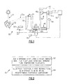
- FIG. 1 illustrates selected portions of an example solar power system 20 for capturing and using solar energy or incidence 22.
- selected components of the solar power system 20 are shown in this example, it is to be understood that additional components may be utilized with the solar power system 20 to generate electricity.
- the disclosed solar power system 20 includes features for controlling electric output, such as to ensure a predictable electrical output, even if the solar energy 22 is poor over a substantial period of time. For instance, the total energy and power available from solar thermal power plants can vary due to solar energy fluctuations. Thus, there exists a need to improve the total energy and power output of solar thermal power plants that reduces or eliminates the need for an expensive reserve power plant.
- the solar power system 20 includes at least one solar receiver 24 through which a working fluid 26 can be circulated.
- the working fluid 26 has a maximum predefined operational temperature.
- the maximum predefined operational temperature can be defined based on a breakdown temperature of the working fluid 26 or system 20 and/or the temperature to which the working fluid 26 is heated to maximize electrical output from the system 20, or a combination of these factors and/or other factors.
- the working fluid 26 is heated to approximately the maximum predefined operational temperature, which in turn produces approximately the maximum electrical output from the system 20. However, if the solar energy 22 is intermediate or poor, the working fluid 26 is not heated to the maximum predefined operational temperature, which results in less electrical output from the system 20. Thus, the electrical output fluctuates in accordance with the strength of the solar energy 22.
- the fluctuation is at least partially mitigated by the thermal capacity of the working fluid 26.
- the working fluid 26 has the ability to retain thermal energy from the solar energy 22 for some amount of time that depends on the fluid selected and storage conditions.
- the electrical output undesirably fluctuates to a greater degree.
- the system 20 and operation as described below reduce the fluctuation and ensure a predictable electrical output.
- the working fluid 26 is circulated through lines 28 or other suitable conduits for handling the particular type of working fluid 26.
- the working fluid 26 is a molten salt, such as potassium nitrite and sodium nitrite.
- the working fluid 26 may alternatively be another type, such as a liquid metal or a fluoride salt or a hydrocarbon such as a synthetic oil. Given this description, one of ordinary skill in the art will recognize suitable working fluids 26 to meet their particular needs.
- the solar power system 20 includes at least one solar collector 30 that is operative to direct the solar energy 22 toward the solar receiver 24 via reflected and/or concentrated rays 22a to heat the working fluid 26 in a known manner.
- the solar collector 30 includes one or more heliostats for tracking and following the sun.
- the solar receiver 24 may include a trough-type solar collectors or other types of solar collectors that are known for receiving the solar energy 22 and transferring heat to the working fluid 26. It is to be understood that the solar power system 20 may be modified from the illustrated example and include other types of solar collectors 30 and solar receivers 24.
- the solar power system 20 further includes a first storage unit 32a and a second storage unit 32b.
- Each of the units 32a and 32b which in some example can include a multiple of such units, includes an internal volume 34 for holding or circulating the working fluid 26.
- the first storage unit 32a is a "hot” storage unit that is connected to receive the working fluid 26 from the solar receiver 24, and the second storage unit 32b is a "cold” storage unit that is connected to provide the working fluid 26 to the solar receiver 24.
- a supplemental heat source 36 is operable to heat the working fluid 26 to approximately the maximum predefined operational temperature.
- the supplemental heat source 36 is an electric resistance heater that is suitably sized to heat the working fluid 26 to approximately the maximum predefined operational temperature.
- the supplemental heat source 36 can also have one or more ceramic heating elements that are capable of withstanding the temperature and chemical conditions within the working fluid 26. As shown, the supplemental heat source 36 is located within the first storage unit 32a. In other examples, the supplemental heat source 36 is located elsewhere in the system 20, such as in the lines 28.
- a power block is generally shown at 40 and is operable to generate electricity in a thermodynamic cycle using heat from the heated working fluid 26.
- the power block 40 includes a turbine 42 having a high pressure section 42a and a low pressure section 42b, an electric generator 44 that is coupled to be driven by the turbine 42, and a heat exchanger 46 for thermal exchange between the working fluid 26 and a second working fluid (e.g., water) that drives the turbine 42.
- a condenser 48 is located between the low pressure turbine section 42b and the heat exchanger 46.
- the generator 44 is electrically connected with an electric grid 50. It is to be understood that the disclosed power block 40 is an example and that other power block configurations can alternatively be used to generate electric output from the thermal energy contained in the working fluid 26.
- a controller 52 is connected with the supplemental heat source 36 to selectively augment heating of the working fluid 26.
- the controller 52 can also be connected with other components in the system 20.
- the controller includes hardware, software or both.
- the controller 52 includes a microprocessor or a computer that is programmed to receive desired inputs and control the supplemental heat source 36 accordingly.
- the supplemental heat source 36 is connected with the electric grid 50 such that when the controller 52 activates the supplemental heat source 36, the supplemental heat source 36 draws power from the electric grid 50.
- the first storage unit 32a operates in one example at a temperature of approximately 1100-1800°F (approximately 593-982°C).
- the second storage unit 32b operates at temperatures of as low as about 500°F (260°C).
- the system 20 and operation described here can also utilize lower operating temperatures; however, this will typically result in lower operating efficiency of the power block 40 and lower total energy capacity of the working fluid 26.
- the working fluid 26 is heated within the solar receiver 24 and circulated into the first storage unit 32a.
- Pumps (not shown) are used to circulate the working fluid 26 through the lines 28 or other type of conduits.
- the working fluid 26 can be temporarily held in the first storage unit 32a or circulated into/from the storage unit 32a, depending on the operational state of the power block 40.
- the working fluid 26 generally is circulated through the first storage unit 32a when the power block 40 is in operation, although the circulation may or may not be continuous.
- the working fluid 26 circulates from the first storage unit 32a to the power block 40 for generating electricity.
- the heated working fluid 26 flows through the heat exchanger 46 to heat the second working fluid, which in this example is water/steam.
- the steam from the heat exchanger 46 drives the high pressure turbine section 42a, which is coupled to drive the generator 44.
- the steam then returns to the heat exchanger 46 to be reheated.
- the reheated steam then drives the low pressure turbine section 42b, which is also coupled to drive the generator 44.
- the steam is then condensed in the condenser 48 before returning to the heat exchanger 46 for another cycle.
- the working fluid After flowing through the heat exchanger 46, the working fluid flows to the second storage unit 32b.
- the relatively cooler working fluid 26 may then be circulated from the second storage unit 32b to the solar receiver 24 for another cycle of use.
- other components may be used in combination with the illustrated components to facilitate or enhance operation of the solar power system 20.
- FIG. 2 shows an example method 60 for use with a solar power system, such as solar power system 20.
- the method 60 will be described with reference to system 20 but it is to be understood that the method 60 is not necessarily limited to the illustrated configuration of system 20.
- the method 60 includes solar heating step 62 and electric heating step 64.
- the working fluid 26 is heated using solar energy 22, as described above.
- the solar energy 22 that is input into the working fluid 26 can be strong, intermediate, or poor and thus fluctuates depending upon the weather conditions.
- the strength of the solar energy 22 is represented by the temperature to which the solar energy 22 heats the working fluid 26.
- a predetermined threshold temperature above the freezing point of the working fluid 26 is set. For example, the predetermined threshold temperature is set according to a minimum desired total energy output from the system 20 and/or to reduce power output fluctuation to within a desired level.
- the working fluid 26 is selectively electrically heated using the supplemental heat source 36 in response to the temperature of the working fluid 26 falling below the predetermined threshold temperature.
- the “selective” heating refers to an intelligent system that has the ability to consider various factors and determine whether or not, and in some examples when, to electrically heat the working fluid 26 in response to the temperature falling below the threshold temperature.
- a predetermined threshold temperature of 800°F/427°C can be set. In other examples, the threshold temperature can be different. If over a period of time the solar energy 22 is unable to maintain the working fluid 26 above the threshold temperature, the controller 52 can activate the supplemental heat source 36 to increase the temperature of the working fluid 26. In one example, the controller 52 activates the supplemental heat source 36 such that the working fluid 26 is maintained at the threshold temperature. In other examples, the controller 52 activates the supplemental heat source 36 such that the working fluid 26 is heated to the maximum operational temperature, or alternatively to an intermediate temperature between the threshold temperature and the maximum operational temperature. By maintaining the temperature of the working fluid 26 at or above the threshold temperature, there is less fluctuation in the power output from the system 20 and the power output is more predictable.
- the controller 52 in response to the temperature of the working fluid 26 falling below the threshold temperature, the controller 52 considers outside factors to determine whether to electrically heat the working fluid 26.
- the controller 52 is provided with weather information or data to determine whether to electrically heat the working fluid 26. For instance, if the temperature of the working fluid 26 falls below the threshold temperature but the weather information suggests that the solar energy 22 is increasing in strength, the controller 52 decides not to electrically heat the working fluid 26. Alternatively, if the temperature of the working fluid 26 falls below the threshold temperature but the weather information suggests that the solar energy 22 is decreasing in strength, the controller 52 decides to electrically heat the working fluid 26.
- the controller 52 is provided with data about the electric grid 50 to determine whether to electrically heat the working fluid 26. For instance, if the temperature of the working fluid 26 falls below the threshold temperature but the data about the electric grid 50 is unfavorable (e.g., economically), the controller 52 decides not to electrically heat the working fluid 26. Alternatively, if the temperature of the working fluid 26 falls below the threshold temperature but the data about the electric grid 50 is favorable, the controller 52 decides to electrically heat the working fluid 26.
- the data about the electric grid 50 includes one or more of the price of electrical power from the electric grid 50, the price of electrical power delivered to the electric grid 50, a level of electric power demand on the electric grid 50, and a level of electric power supply to the electric grid 50.
- FIG. 3 shows another example method 70 for use with a solar power system, such as solar power system 20. Similar to the method 60, the method 70 will be described with reference to system 20 but it is to be understood that the method 70 is not necessarily limited to the configuration of system 20.
- the method 70 generally includes a solar heating step 72, a prediction step 74, a decision step 76 and an electric heating step 78.
- the solar heating step 72 is similar to the solar heating step 62 described above.
- the controller 52 predicts a future time when the temperature of the working fluid 26 will be below the predetermined threshold temperature.
- the controller 52 is provided with forecast weather information or data for a period of time into the future, such as hours, days or weeks, as a basis for the prediction. Based on the weather information, the controller 52 estimates a future time when the solar energy 22 will be insufficient to maintain the temperature of the working fluid 26 above the predetermined threshold temperature, given the known thermal capacity of the working fluid 26 and system 20.
- the controller 52 decides whether and at what future time to electrically heat the working fluid 26 based on provided data about the electric grid 50.
- the controller 52 can be provided with data such as estimates of the price of electrical power to and from the electric grid 50 at the predicted future time, a level of electric power demand on the electric grid 50 at the predicted future time, and a level of electric power supply to the electric grid 50 at the predicted future time.
- the decision of whether to electrically heat the working fluid 26 is based on the price of electrical power from the electric grid 50 at the predicted future time. If the price is high, such as during the day, the controller 52 decides not to electrically heat the working fluid 26. On the other hand, if the price is low, such as during the night, the controller 52 may decide to electrically heat the working fluid 26 at a future time. This future time when the heating occurs may be the same as the predicted future time when the temperature of the working fluid 26 will be below the predetermined threshold temperature; however, it may be at an even later time when the price of electrical power from the electric grid 50 is even more favorable (i.e., less expensive).
- the decision of whether to electrically heat the working fluid 26 is based on the overall supply and/or demand of electric power on the electric grid 50 at a predicted future period of time, which is typically during the peak electrical demand period of the following day. If it is forecast that there will be a relatively high supply and low demand, such as a moderate temperature day, the controller 52 decides not to electrically heat the working fluid 26. On the other hand, if it is forecast that there will be a relatively low supply and high demand, such as an especially hot day, the controller 52 decides to electrically heat the working fluid 26. Preferably, this heating is completed during a period when the price of electrical power from the electric grid 50 is at a minimum (i.e., at night).
- controller 52 decides to electrically heat the working fluid 26
- the controller 52 then activates the supplemental heat source 36 during the desired period to heat the working fluid 26.
- the decision of whether to electrically heat the working fluid 26 is based on a balance between the price of electrical power from the electric grid 50 during the heating period (step 64 or 78), the overall supply and demand of electric power on the electric grid 50 at the predicted future time, and/or the price of electrical power supplied to the electric grid 50 at a future time and the round-trip efficiency of the system 20 with regard to the amount of electrical energy input into the heater versus the amount of electrical output from the system due the input electrical energy.
- the system 20 can be utilized for electric energy storage when it is economically advantageous, for example.
- the controller 52 can electrically heat the working fluid 26.
- the system 20 can be used to store negative-cost electricity from the electric grid 50.
- the controller 52 can be provided with the negative cost information and electrically heat the working fluid 26 in response if the working fluid 26 has thermal capacity. If the working fluid 26 has little or no thermal capacity, the controller 52 can circulate the working fluid 26 through the system 20 to reduce the temperature and then continue to electrically heat the working fluid 26 with the negative-cost electricity from the electric grid 50.
- the system 20 can be utilized to maintain electric output when portions of the system 20 are inoperative or shut down for maintenance.
- the controller 52 can activate the supplemental heat source 36 to maintain the working fluid 26 above the threshold temperature and thereby maintain electrical output from the system 20.
- the supplemental heat source 36 further reduces or eliminates the need for an expensive reserve power plant.
Abstract
Description
- This disclosure relates to power plants for generating electricity.
- Solar power plants for capturing solar energy and generating electricity are known and used. For instance, a solar collector system may direct solar energy into a heat-absorbing fluid, such as a molten salt or a synthetic oil. The heated fluid is used to generate electrical power using a thermodynamic cycle, such as producing steam to drive a turbine to generate electricity. The heat-absorbing fluid may be stored in or circulated through one or more tanks. Since the energy collected in such solar thermal power plants can be stored, the power output is more dispatchable than solar power devices that do not include any means of energy storage, such as photovoltaic cells.
- The various features and advantages of the disclosed examples will become apparent to those skilled in the art from the following detailed description. The drawings that accompany the detailed description can be briefly described as follows.
-
Figure 1 shows an example solar power system having a heater. -
Figure 2 shows an example method for use with a solar power system. -
Figure 3 shows another example method for use with a solar power system. -
Figure 1 illustrates selected portions of an examplesolar power system 20 for capturing and using solar energy orincidence 22. Although selected components of thesolar power system 20 are shown in this example, it is to be understood that additional components may be utilized with thesolar power system 20 to generate electricity. As will be described in further detail, the disclosedsolar power system 20 includes features for controlling electric output, such as to ensure a predictable electrical output, even if thesolar energy 22 is poor over a substantial period of time. For instance, the total energy and power available from solar thermal power plants can vary due to solar energy fluctuations. Thus, there exists a need to improve the total energy and power output of solar thermal power plants that reduces or eliminates the need for an expensive reserve power plant. - The
solar power system 20 includes at least onesolar receiver 24 through which a workingfluid 26 can be circulated. The workingfluid 26 has a maximum predefined operational temperature. For instance, the maximum predefined operational temperature can be defined based on a breakdown temperature of the workingfluid 26 orsystem 20 and/or the temperature to which the workingfluid 26 is heated to maximize electrical output from thesystem 20, or a combination of these factors and/or other factors. - If the
solar energy 22 is strong, the workingfluid 26 is heated to approximately the maximum predefined operational temperature, which in turn produces approximately the maximum electrical output from thesystem 20. However, if thesolar energy 22 is intermediate or poor, the workingfluid 26 is not heated to the maximum predefined operational temperature, which results in less electrical output from thesystem 20. Thus, the electrical output fluctuates in accordance with the strength of thesolar energy 22. - The fluctuation is at least partially mitigated by the thermal capacity of the working
fluid 26. For instance, the workingfluid 26 has the ability to retain thermal energy from thesolar energy 22 for some amount of time that depends on the fluid selected and storage conditions. However, if thesolar energy 22 remains intermediate or poor over a period of time that is greater than the thermal storage capacity of the workingfluid 26, the electrical output undesirably fluctuates to a greater degree. Thesystem 20 and operation as described below reduce the fluctuation and ensure a predictable electrical output. - The working
fluid 26 is circulated throughlines 28 or other suitable conduits for handling the particular type of workingfluid 26. In one example, the workingfluid 26 is a molten salt, such as potassium nitrite and sodium nitrite. However, depending upon the type of system used, the workingfluid 26 may alternatively be another type, such as a liquid metal or a fluoride salt or a hydrocarbon such as a synthetic oil. Given this description, one of ordinary skill in the art will recognizesuitable working fluids 26 to meet their particular needs. - The
solar power system 20 includes at least onesolar collector 30 that is operative to direct thesolar energy 22 toward thesolar receiver 24 via reflected and/or concentratedrays 22a to heat the workingfluid 26 in a known manner. As an example, thesolar collector 30 includes one or more heliostats for tracking and following the sun. - As an alternative to the
centralized receiver 24 or "tower" collector shown inFigure 1 , thesolar receiver 24 may include a trough-type solar collectors or other types of solar collectors that are known for receiving thesolar energy 22 and transferring heat to the workingfluid 26. It is to be understood that thesolar power system 20 may be modified from the illustrated example and include other types ofsolar collectors 30 andsolar receivers 24. - The
solar power system 20 further includes afirst storage unit 32a and asecond storage unit 32b. Each of theunits internal volume 34 for holding or circulating the workingfluid 26. In this example, thefirst storage unit 32a is a "hot" storage unit that is connected to receive the workingfluid 26 from thesolar receiver 24, and thesecond storage unit 32b is a "cold" storage unit that is connected to provide the workingfluid 26 to thesolar receiver 24. - A
supplemental heat source 36 is operable to heat the workingfluid 26 to approximately the maximum predefined operational temperature. In one example, thesupplemental heat source 36 is an electric resistance heater that is suitably sized to heat the workingfluid 26 to approximately the maximum predefined operational temperature. Thesupplemental heat source 36 can also have one or more ceramic heating elements that are capable of withstanding the temperature and chemical conditions within the workingfluid 26. As shown, thesupplemental heat source 36 is located within thefirst storage unit 32a. In other examples, thesupplemental heat source 36 is located elsewhere in thesystem 20, such as in thelines 28. - A power block is generally shown at 40 and is operable to generate electricity in a thermodynamic cycle using heat from the heated working
fluid 26. In the illustrated example, thepower block 40 includes aturbine 42 having a high pressure section 42a and alow pressure section 42b, anelectric generator 44 that is coupled to be driven by theturbine 42, and aheat exchanger 46 for thermal exchange between the workingfluid 26 and a second working fluid (e.g., water) that drives theturbine 42. Acondenser 48 is located between the lowpressure turbine section 42b and theheat exchanger 46. Thegenerator 44 is electrically connected with anelectric grid 50. It is to be understood that the disclosedpower block 40 is an example and that other power block configurations can alternatively be used to generate electric output from the thermal energy contained in the workingfluid 26. - A
controller 52 is connected with thesupplemental heat source 36 to selectively augment heating of the workingfluid 26. Thecontroller 52 can also be connected with other components in thesystem 20. In embodiments, the controller includes hardware, software or both. For example, thecontroller 52 includes a microprocessor or a computer that is programmed to receive desired inputs and control thesupplemental heat source 36 accordingly. In this example, thesupplemental heat source 36 is connected with theelectric grid 50 such that when thecontroller 52 activates thesupplemental heat source 36, thesupplemental heat source 36 draws power from theelectric grid 50. - Depending on system factors and the type of working
fluid 26 that are used, thefirst storage unit 32a operates in one example at a temperature of approximately 1100-1800°F (approximately 593-982°C). Thesecond storage unit 32b operates at temperatures of as low as about 500°F (260°C). Thesystem 20 and operation described here can also utilize lower operating temperatures; however, this will typically result in lower operating efficiency of thepower block 40 and lower total energy capacity of the workingfluid 26. - In operation of
system 20, theworking fluid 26 is heated within thesolar receiver 24 and circulated into thefirst storage unit 32a. Pumps (not shown) are used to circulate the workingfluid 26 through thelines 28 or other type of conduits. The workingfluid 26 can be temporarily held in thefirst storage unit 32a or circulated into/from thestorage unit 32a, depending on the operational state of thepower block 40. Thus, the workingfluid 26 generally is circulated through thefirst storage unit 32a when thepower block 40 is in operation, although the circulation may or may not be continuous. - The working
fluid 26 circulates from thefirst storage unit 32a to thepower block 40 for generating electricity. The heated workingfluid 26 flows through theheat exchanger 46 to heat the second working fluid, which in this example is water/steam. The steam from theheat exchanger 46 drives the high pressure turbine section 42a, which is coupled to drive thegenerator 44. The steam then returns to theheat exchanger 46 to be reheated. The reheated steam then drives the lowpressure turbine section 42b, which is also coupled to drive thegenerator 44. The steam is then condensed in thecondenser 48 before returning to theheat exchanger 46 for another cycle. - After flowing through the
heat exchanger 46, the working fluid flows to thesecond storage unit 32b. The relatively cooler workingfluid 26 may then be circulated from thesecond storage unit 32b to thesolar receiver 24 for another cycle of use. As can be appreciated, other components may be used in combination with the illustrated components to facilitate or enhance operation of thesolar power system 20. -
Figure 2 shows anexample method 60 for use with a solar power system, such assolar power system 20. Themethod 60 will be described with reference tosystem 20 but it is to be understood that themethod 60 is not necessarily limited to the illustrated configuration ofsystem 20. - The
method 60 includessolar heating step 62 andelectric heating step 64. In thesolar heating step 62, the workingfluid 26 is heated usingsolar energy 22, as described above. As described, thesolar energy 22 that is input into the workingfluid 26 can be strong, intermediate, or poor and thus fluctuates depending upon the weather conditions. The strength of thesolar energy 22 is represented by the temperature to which thesolar energy 22 heats the workingfluid 26. A predetermined threshold temperature above the freezing point of the workingfluid 26 is set. For example, the predetermined threshold temperature is set according to a minimum desired total energy output from thesystem 20 and/or to reduce power output fluctuation to within a desired level. - In the
electric heating step 64, the workingfluid 26 is selectively electrically heated using thesupplemental heat source 36 in response to the temperature of the workingfluid 26 falling below the predetermined threshold temperature. The "selective" heating refers to an intelligent system that has the ability to consider various factors and determine whether or not, and in some examples when, to electrically heat the workingfluid 26 in response to the temperature falling below the threshold temperature. - As an example, to reduce fluctuation in the power output from the
system 20 and to maintain a desired power output, a predetermined threshold temperature of 800°F/427°C can be set. In other examples, the threshold temperature can be different. If over a period of time thesolar energy 22 is unable to maintain the workingfluid 26 above the threshold temperature, thecontroller 52 can activate thesupplemental heat source 36 to increase the temperature of the workingfluid 26. In one example, thecontroller 52 activates thesupplemental heat source 36 such that the workingfluid 26 is maintained at the threshold temperature. In other examples, thecontroller 52 activates thesupplemental heat source 36 such that the workingfluid 26 is heated to the maximum operational temperature, or alternatively to an intermediate temperature between the threshold temperature and the maximum operational temperature. By maintaining the temperature of the workingfluid 26 at or above the threshold temperature, there is less fluctuation in the power output from thesystem 20 and the power output is more predictable. - In further examples, in response to the temperature of the working
fluid 26 falling below the threshold temperature, thecontroller 52 considers outside factors to determine whether to electrically heat the workingfluid 26. - In one example, the
controller 52 is provided with weather information or data to determine whether to electrically heat the workingfluid 26. For instance, if the temperature of the workingfluid 26 falls below the threshold temperature but the weather information suggests that thesolar energy 22 is increasing in strength, thecontroller 52 decides not to electrically heat the workingfluid 26. Alternatively, if the temperature of the workingfluid 26 falls below the threshold temperature but the weather information suggests that thesolar energy 22 is decreasing in strength, thecontroller 52 decides to electrically heat the workingfluid 26. - In a further example, the
controller 52 is provided with data about theelectric grid 50 to determine whether to electrically heat the workingfluid 26. For instance, if the temperature of the workingfluid 26 falls below the threshold temperature but the data about theelectric grid 50 is unfavorable (e.g., economically), thecontroller 52 decides not to electrically heat the workingfluid 26. Alternatively, if the temperature of the workingfluid 26 falls below the threshold temperature but the data about theelectric grid 50 is favorable, thecontroller 52 decides to electrically heat the workingfluid 26. - In some examples, the data about the
electric grid 50 includes one or more of the price of electrical power from theelectric grid 50, the price of electrical power delivered to theelectric grid 50, a level of electric power demand on theelectric grid 50, and a level of electric power supply to theelectric grid 50. -
Figure 3 shows anotherexample method 70 for use with a solar power system, such assolar power system 20. Similar to themethod 60, themethod 70 will be described with reference tosystem 20 but it is to be understood that themethod 70 is not necessarily limited to the configuration ofsystem 20. - The
method 70 generally includes a solar heating step 72, aprediction step 74, adecision step 76 and anelectric heating step 78. The solar heating step 72 is similar to thesolar heating step 62 described above. - At the
prediction step 74, thecontroller 52 predicts a future time when the temperature of the workingfluid 26 will be below the predetermined threshold temperature. In one example, thecontroller 52 is provided with forecast weather information or data for a period of time into the future, such as hours, days or weeks, as a basis for the prediction. Based on the weather information, thecontroller 52 estimates a future time when thesolar energy 22 will be insufficient to maintain the temperature of the workingfluid 26 above the predetermined threshold temperature, given the known thermal capacity of the workingfluid 26 andsystem 20. - At the
decision step 76, thecontroller 52 decides whether and at what future time to electrically heat the workingfluid 26 based on provided data about theelectric grid 50. As described above, thecontroller 52 can be provided with data such as estimates of the price of electrical power to and from theelectric grid 50 at the predicted future time, a level of electric power demand on theelectric grid 50 at the predicted future time, and a level of electric power supply to theelectric grid 50 at the predicted future time. - In one example, the decision of whether to electrically heat the working
fluid 26 is based on the price of electrical power from theelectric grid 50 at the predicted future time. If the price is high, such as during the day, thecontroller 52 decides not to electrically heat the workingfluid 26. On the other hand, if the price is low, such as during the night, thecontroller 52 may decide to electrically heat the workingfluid 26 at a future time. This future time when the heating occurs may be the same as the predicted future time when the temperature of the workingfluid 26 will be below the predetermined threshold temperature; however, it may be at an even later time when the price of electrical power from theelectric grid 50 is even more favorable (i.e., less expensive). - In another example, the decision of whether to electrically heat the working
fluid 26 is based on the overall supply and/or demand of electric power on theelectric grid 50 at a predicted future period of time, which is typically during the peak electrical demand period of the following day. If it is forecast that there will be a relatively high supply and low demand, such as a moderate temperature day, thecontroller 52 decides not to electrically heat the workingfluid 26. On the other hand, if it is forecast that there will be a relatively low supply and high demand, such as an especially hot day, thecontroller 52 decides to electrically heat the workingfluid 26. Preferably, this heating is completed during a period when the price of electrical power from theelectric grid 50 is at a minimum (i.e., at night). - If the
controller 52 decides to electrically heat the workingfluid 26, thecontroller 52 then activates thesupplemental heat source 36 during the desired period to heat the workingfluid 26. - In a further example, the decision of whether to electrically heat the working
fluid 26 is based on a balance between the price of electrical power from theelectric grid 50 during the heating period (step 64 or 78), the overall supply and demand of electric power on theelectric grid 50 at the predicted future time, and/or the price of electrical power supplied to theelectric grid 50 at a future time and the round-trip efficiency of thesystem 20 with regard to the amount of electrical energy input into the heater versus the amount of electrical output from the system due the input electrical energy. - In addition to or instead of the above-described control strategies, the
system 20 can be utilized for electric energy storage when it is economically advantageous, for example. For instance, if the workingfluid 26 has remaining capacity to be heated, thecontroller 52 can electrically heat the workingfluid 26. In a further example, thesystem 20 can be used to store negative-cost electricity from theelectric grid 50. As an example, if demand is low at night and there is a surplus of electricity during that time the cost of electricity delivered from the grid can be negative, such as when the wind is especially strong at night in a region with a large number of wind turbines. Thecontroller 52 can be provided with the negative cost information and electrically heat the workingfluid 26 in response if the workingfluid 26 has thermal capacity. If the workingfluid 26 has little or no thermal capacity, thecontroller 52 can circulate the workingfluid 26 through thesystem 20 to reduce the temperature and then continue to electrically heat the workingfluid 26 with the negative-cost electricity from theelectric grid 50. - In addition to or instead of the above-described control strategies, the
system 20 can be utilized to maintain electric output when portions of thesystem 20 are inoperative or shut down for maintenance. For example, if all or part of thesolar receiver 24 and/orsolar collectors 30 are inoperative or shut down for maintenance, thecontroller 52 can activate thesupplemental heat source 36 to maintain the workingfluid 26 above the threshold temperature and thereby maintain electrical output from thesystem 20. Thus, thesupplemental heat source 36 further reduces or eliminates the need for an expensive reserve power plant. - Although a combination of features is shown in the illustrated examples, not all of them need to be combined to realize the benefits of various embodiments of this disclosure. In other words, a system designed according to an embodiment of this disclosure will not necessarily include all of the features shown in any one of the Figures or all of the portions schematically shown in the Figures. Moreover, selected features of one example embodiment may be combined with selected features of other example embodiments.
- The preceding description is exemplary rather than limiting in nature. Variations and modifications to the disclosed examples may become apparent to those skilled in the art that do not necessarily depart from the essence of this disclosure. The scope of legal protection given to this disclosure can only be determined by studying the following claims.
Claims (15)
- A method for controlling electric output, the method comprising:heating a fluid with solar incidence;generating electricity from the heated fluid using a thermodynamic cycle;
andselectively augmenting the heating of the fluid with a supplementary heat source to control the generating of the electricity. - The method of claim 1 comprising:heating a working fluid using a solar energy input that fluctuates such that the temperature of the working fluid fluctuates above and below a predetermined threshold temperature that is above the freezing point of the working fluid, wherein an electric power output to an electric grid fluctuates in accordance with the solar energy input; andselectively electrically heating the working fluid in response to the temperature of the working fluid falling below the predetermined threshold temperature to reduce fluctuation in the electric power output to the electric grid.
- The method as recited in claim 2, including electrically heating the working fluid to approximately a maximum predefined operational temperature of the working fluid.
- The method as recited in claim 2 or 3, including selectively electrically heating the working fluid responsive to weather information and/or responsive to data about the electric grid.
- The method as recited in claim 2, 3 or 4, including selectively electrically heating the working fluid in response to at least one of a negative cost information from the electric grid, price of electrical power from the electric grid, price of electrical power supplied to the electric grid, a level of electric power demand on the electric grid, and a level of electric power supply to the electric grid.
- A method for a solar power system, the method comprising:heating a working fluid using a solar energy input that fluctuates such that the temperature of the working fluid fluctuates above and below a predetermined threshold temperature, wherein an electric power output to an electric grid fluctuates in accordance with the solar energy input;predicting a future time when the temperature of the working fluid will be below the predetermined threshold temperature;based on data about the electric grid, deciding whether and at what future time to electrically heat the working fluid; andelectrically heating the working fluid at the selected future time.
- The method as recited in claim 6, including predicting the future time when the solar energy input will be below the predetermined threshold responsive to weather information.
- The method as recited in claim 6 or 7, wherein the data about the electric grid includes at least one of a predicted future electric power demand on the electric grid or a predicted future electric power supply to the electric grid.
- A solar power system comprising:a solar energy collector including at least one solar receiver operable to carry a working fluid and at least one solar reflector operable to direct solar energy towards the at least one solar receiver to heat the working fluid, the working fluid having a maximum predefined operational temperature up to which it can be heated;at least one storage unit including an internal volume connected to receive the working fluid from the at least one solar receiver;a power block operable to generate electricity using heat from the heated working fluid; anda heater operable to heat the working fluid to approximately the maximum predefined operational temperature.
- The solar power system as recited in claim 9, wherein the heater is arranged within the interior volume of at least one storage unit.
- The solar power system as recited in claim 9 or 10, including a controller in communication with the heater.
- The solar power system as recited in claim 11, wherein the controller is configured to control the heater based upon weather information; and/or
wherein the controller is configured to control the heater responsive to data about an electric grid to which the power block is connected; and/or
wherein the controller is configured to control the heater responsive to a predicted future price of electrical power. - The solar power system as recited in claim 11 or 12, wherein the controller is configured to control the heater responsive to a predicted future electric power supply and/or demand on an electric grid to which the power block is connected.
- The solar power system as recited in claim 11, 12 or 13, wherein the controller is configured to control the heater responsive to negative-cost electricity from an electric grid.
- The method or solar power system as recited in any one of claims 1 to 14, wherein the working fluid comprises a molten salt.
Applications Claiming Priority (1)
| Application Number | Priority Date | Filing Date | Title |
|---|---|---|---|
| US13/248,395 US9816491B2 (en) | 2011-09-29 | 2011-09-29 | Solar power system and method therefor |
Publications (2)
| Publication Number | Publication Date |
|---|---|
| EP2574784A2 true EP2574784A2 (en) | 2013-04-03 |
| EP2574784A3 EP2574784A3 (en) | 2016-11-16 |
Family
ID=47469738
Family Applications (1)
| Application Number | Title | Priority Date | Filing Date |
|---|---|---|---|
| EP12185909.4A Withdrawn EP2574784A3 (en) | 2011-09-29 | 2012-09-25 | Solar power system and method therefor |
Country Status (3)
| Country | Link |
|---|---|
| US (1) | US9816491B2 (en) |
| EP (1) | EP2574784A3 (en) |
| ZA (1) | ZA201205962B (en) |
Cited By (5)
| Publication number | Priority date | Publication date | Assignee | Title |
|---|---|---|---|---|
| EP2778406A1 (en) * | 2013-03-14 | 2014-09-17 | ABB Technology AG | Thermal energy storage and generation system and method |
| WO2015088755A1 (en) * | 2013-12-13 | 2015-06-18 | Chromalox, Inc. | Energy storage systems with medium voltage electrical heat exchangers |
| EP3075969A1 (en) * | 2015-03-31 | 2016-10-05 | Siemens Aktiengesellschaft | Energy storage system and method |
| WO2017057261A1 (en) * | 2015-09-30 | 2017-04-06 | 日立造船株式会社 | Steam generation device |
| WO2020166526A1 (en) * | 2019-02-14 | 2020-08-20 | 株式会社Ihi | Vapor supply device and drying system |
Families Citing this family (32)
| Publication number | Priority date | Publication date | Assignee | Title |
|---|---|---|---|---|
| US10094219B2 (en) | 2010-03-04 | 2018-10-09 | X Development Llc | Adiabatic salt energy storage |
| US9038387B2 (en) * | 2011-08-31 | 2015-05-26 | Brightsource Industries (Israel) Ltd | Solar thermal electricity generating systems with thermal storage |
| US20140366536A1 (en) * | 2011-11-08 | 2014-12-18 | Abengoa Solar Llc | High temperature thermal energy for grid storage and concentrated solar plant enhancement |
| JP5868809B2 (en) * | 2012-08-06 | 2016-02-24 | 株式会社東芝 | Power plant and heat supply method |
| WO2014052927A1 (en) | 2012-09-27 | 2014-04-03 | Gigawatt Day Storage Systems, Inc. | Systems and methods for energy storage and retrieval |
| US9778627B2 (en) * | 2012-11-16 | 2017-10-03 | Siemens Aktiengesellschaft | Method of controlling a power network |
| US9541071B2 (en) | 2012-12-04 | 2017-01-10 | Brightsource Industries (Israel) Ltd. | Concentrated solar power plant with independent superheater |
| US9518873B2 (en) * | 2013-06-27 | 2016-12-13 | Google Technology Holdings LLC | Electronic system and method for thermal management therein taking into account solar thermal loading |
| US10323543B2 (en) * | 2014-07-28 | 2019-06-18 | Third Power, LLC | Conversion of power plants to energy storage resources |
| EP3242012B1 (en) * | 2014-12-31 | 2023-10-18 | Shenzhen Enesoon Science & Technology Co., Ltd. | Combined energy supply system of wind, photovoltaic, solar thermal power and medium-based heat storage |
| US10326276B2 (en) | 2015-04-06 | 2019-06-18 | Solarreserve Technology, Llc | Electrical power systems incorporating thermal energy storage |
| JP6596303B2 (en) * | 2015-10-28 | 2019-10-23 | 千代田化工建設株式会社 | Solar thermal power generation apparatus and control method thereof |
| US10233833B2 (en) | 2016-12-28 | 2019-03-19 | Malta Inc. | Pump control of closed cycle power generation system |
| US11053847B2 (en) | 2016-12-28 | 2021-07-06 | Malta Inc. | Baffled thermoclines in thermodynamic cycle systems |
| US10221775B2 (en) | 2016-12-29 | 2019-03-05 | Malta Inc. | Use of external air for closed cycle inventory control |
| US10436109B2 (en) | 2016-12-31 | 2019-10-08 | Malta Inc. | Modular thermal storage |
| CN108171363B (en) * | 2017-12-13 | 2022-08-26 | 北京金风慧能技术有限公司 | Method and device for predicting photo-thermal power generation power |
| US10608467B2 (en) * | 2018-01-12 | 2020-03-31 | Katerra Inc. | Supplying electrical power to multiple loads from more than one power source |
| US10987609B1 (en) * | 2018-02-11 | 2021-04-27 | John D. Walker | Polar-linear-fresnel-concentrating solar-thermal power and desalination plant |
| CN108533467A (en) * | 2018-02-26 | 2018-09-14 | 华北电力大学 | A kind of slot type of power regulation, tower photo-thermal and photovoltaic can heat accumulation electricity generation systems |
| GB201808478D0 (en) * | 2018-05-23 | 2018-07-11 | Univ Edinburgh | Ultra-high temperature thermal energy storage system |
| CN116557091A (en) | 2019-11-16 | 2023-08-08 | 马耳他股份有限公司 | Dual power system pumped thermal energy storage with thermal storage medium rebalancing |
| US11519294B2 (en) * | 2019-11-25 | 2022-12-06 | Raytheon Technologies Corporation | Aircraft propulsion system with vapor absorption refrigeration system |
| US11454167B1 (en) * | 2020-08-12 | 2022-09-27 | Malta Inc. | Pumped heat energy storage system with hot-side thermal integration |
| US11286804B2 (en) | 2020-08-12 | 2022-03-29 | Malta Inc. | Pumped heat energy storage system with charge cycle thermal integration |
| US11480067B2 (en) | 2020-08-12 | 2022-10-25 | Malta Inc. | Pumped heat energy storage system with generation cycle thermal integration |
| US11396826B2 (en) | 2020-08-12 | 2022-07-26 | Malta Inc. | Pumped heat energy storage system with electric heating integration |
| AU2021385430A1 (en) | 2020-11-30 | 2023-07-06 | Rondo Energy, Inc. | Energy storage system and applications |
| US11913362B2 (en) | 2020-11-30 | 2024-02-27 | Rondo Energy, Inc. | Thermal energy storage system coupled with steam cracking system |
| CN112524841B (en) * | 2020-11-30 | 2022-08-30 | 上海发电设备成套设计研究院有限责任公司 | Heat pump energy storage system |
| US20230296034A1 (en) * | 2020-11-30 | 2023-09-21 | Rondo Energy, Inc. | Thermal energy storage system coupled with thermal power cycle systems |
| US11913361B2 (en) | 2020-11-30 | 2024-02-27 | Rondo Energy, Inc. | Energy storage system and alumina calcination applications |
Family Cites Families (34)
| Publication number | Priority date | Publication date | Assignee | Title |
|---|---|---|---|---|
| US4055948A (en) * | 1975-12-08 | 1977-11-01 | Kraus Robert A | Solar thermal-radiation, absorption and conversion system |
| US4205656A (en) | 1978-06-06 | 1980-06-03 | Scarlata Robert W | Thermal storage reservoirs |
| US4248291A (en) | 1978-10-18 | 1981-02-03 | Seymour Jarmul | Compact thermal energy reservoirs |
| US4394814A (en) * | 1981-04-01 | 1983-07-26 | Wardman John C | Energy generation system |
| US4438630A (en) * | 1982-09-07 | 1984-03-27 | Combustion Engineering, Inc. | Method and system for maintaining operating temperatures in a molten salt co-generating unit |
| US5384489A (en) * | 1994-02-07 | 1995-01-24 | Bellac; Alphonse H. | Wind-powered electricity generating system including wind energy storage |
| US6494042B2 (en) | 2001-02-12 | 2002-12-17 | Ormat Industries Ltd. | Method of and apparatus for producing uninterruptible power |
| US6701711B1 (en) * | 2002-11-11 | 2004-03-09 | The Boeing Company | Molten salt receiver cooling system |
| US6877508B2 (en) * | 2002-11-22 | 2005-04-12 | The Boeing Company | Expansion bellows for use in solar molten salt piping and valves |
| US7051529B2 (en) * | 2002-12-20 | 2006-05-30 | United Technologies Corporation | Solar dish concentrator with a molten salt receiver incorporating thermal energy storage |
| US20070157614A1 (en) * | 2003-01-21 | 2007-07-12 | Goldman Arnold J | Hybrid Generation with Alternative Fuel Sources |
| US7086231B2 (en) * | 2003-02-05 | 2006-08-08 | Active Power, Inc. | Thermal and compressed air storage system |
| US6957536B2 (en) * | 2003-06-03 | 2005-10-25 | The Boeing Company | Systems and methods for generating electrical power from solar energy |
| US7055519B2 (en) * | 2003-12-10 | 2006-06-06 | United Technologies Corporation | Solar collector and method |
| US7296410B2 (en) | 2003-12-10 | 2007-11-20 | United Technologies Corporation | Solar power system and method for power generation |
| US7340899B1 (en) * | 2004-10-26 | 2008-03-11 | Solar Energy Production Corporation | Solar power generation system |
| US8365529B2 (en) * | 2006-06-30 | 2013-02-05 | United Technologies Corporation | High temperature molten salt receiver |
| CN102723390A (en) * | 2006-08-08 | 2012-10-10 | Pvt太阳能有限公司 | Topologies, systems and methods for control of solar energy supply systems |
| US8544272B2 (en) * | 2007-06-11 | 2013-10-01 | Brightsource Industries (Israel) Ltd. | Solar receiver |
| FR2927959A1 (en) * | 2008-02-27 | 2009-08-28 | Sophia Antipolis En Dev Soc Pa | INSTALLATION FOR GENERATING ELECTRIC ENERGY FROM SOLAR ENERGY. |
| US7987844B2 (en) * | 2009-01-13 | 2011-08-02 | Hamilton Sundstrand Corporation | Catalyzed hot gas heating system for concentrated solar power generation systems |
| US8596060B2 (en) | 2009-05-29 | 2013-12-03 | Toyota Motor Engineering & Manufacturing North America, Inc. | Systems and method for producing mechanical energy |
| US9657966B2 (en) * | 2009-06-01 | 2017-05-23 | Solarreserve | Single bi-temperature thermal storage tank for application in solar thermal plant |
| US20110016864A1 (en) | 2009-07-23 | 2011-01-27 | Electric Power Research Institute, Inc. | Energy storage system |
| US8327641B2 (en) * | 2009-12-01 | 2012-12-11 | General Electric Company | System for generation of power using solar energy |
| EP2369288A1 (en) | 2010-03-11 | 2011-09-28 | Siemens Aktiengesellschaft | Energy transfer system comprising a phase change material |
| WO2012148551A2 (en) | 2011-02-24 | 2012-11-01 | Bluelagoon Energy Technologies Ltd. | Methods and apparatus for latent heat (phase change) thermal storage and associated heat transfer and exchange |
| WO2013014664A2 (en) | 2011-07-27 | 2013-01-31 | Yehuda Harats | System for improved hybridization of thermal solar and biomass and fossil fuel based energy systems |
| US9038387B2 (en) | 2011-08-31 | 2015-05-26 | Brightsource Industries (Israel) Ltd | Solar thermal electricity generating systems with thermal storage |
| US9046307B2 (en) * | 2012-05-02 | 2015-06-02 | Brightsource Industries (Israel) Ltd. | Integrated solar energy thermal storage system and methods |
| WO2014052927A1 (en) | 2012-09-27 | 2014-04-03 | Gigawatt Day Storage Systems, Inc. | Systems and methods for energy storage and retrieval |
| WO2014176290A2 (en) | 2013-04-22 | 2014-10-30 | Genie Ip B.V. | Wind-heated molten salt as a thermal buffer for producing oil from unconventional resources |
| US20160072291A1 (en) | 2013-04-25 | 2016-03-10 | Mada Energie Ltd | Energy processing and storage |
| US10402185B2 (en) * | 2015-09-11 | 2019-09-03 | Sap Se | Precision locking a database server during the upgrade of a system landscape |
-
2011
- 2011-09-29 US US13/248,395 patent/US9816491B2/en not_active Expired - Fee Related
-
2012
- 2012-08-07 ZA ZA2012/05962A patent/ZA201205962B/en unknown
- 2012-09-25 EP EP12185909.4A patent/EP2574784A3/en not_active Withdrawn
Non-Patent Citations (1)
| Title |
|---|
| None |
Cited By (7)
| Publication number | Priority date | Publication date | Assignee | Title |
|---|---|---|---|---|
| EP2778406A1 (en) * | 2013-03-14 | 2014-09-17 | ABB Technology AG | Thermal energy storage and generation system and method |
| WO2015088755A1 (en) * | 2013-12-13 | 2015-06-18 | Chromalox, Inc. | Energy storage systems with medium voltage electrical heat exchangers |
| US9523285B2 (en) | 2013-12-13 | 2016-12-20 | Chromalox, Inc. | Energy storage systems with medium voltage electrical heat exchangers |
| EP3075969A1 (en) * | 2015-03-31 | 2016-10-05 | Siemens Aktiengesellschaft | Energy storage system and method |
| WO2016156177A1 (en) * | 2015-03-31 | 2016-10-06 | Siemens Aktiengesellschaft | Energy storage system and method |
| WO2017057261A1 (en) * | 2015-09-30 | 2017-04-06 | 日立造船株式会社 | Steam generation device |
| WO2020166526A1 (en) * | 2019-02-14 | 2020-08-20 | 株式会社Ihi | Vapor supply device and drying system |
Also Published As
| Publication number | Publication date |
|---|---|
| ZA201205962B (en) | 2013-04-24 |
| US20130081394A1 (en) | 2013-04-04 |
| US9816491B2 (en) | 2017-11-14 |
| EP2574784A3 (en) | 2016-11-16 |
Similar Documents
| Publication | Publication Date | Title |
|---|---|---|
| US9816491B2 (en) | Solar power system and method therefor | |
| CN108291532B (en) | Solar power generation device and control method thereof | |
| US20140352304A1 (en) | Hybrid solar field | |
| US20120102950A1 (en) | Solar thermal power plant with the integration of an aeroderivative turbine | |
| US20140223906A1 (en) | Solar/gas hybrid power system configurations and methods of use | |
| US20080066736A1 (en) | Method and apparatus for solar energy storage system using gas and rock | |
| JP5510506B2 (en) | Solar system | |
| WO2012107811A2 (en) | Solar energy storage system including three or more reservoirs | |
| EP3032099B1 (en) | Solar thermal power generation system | |
| KR20150082431A (en) | Thermal energy storage system comprising a combined heating and cooling machine and a method for using the thermal energy storage system | |
| EP2653801A1 (en) | Solar power system and method of operation | |
| EP3559559B1 (en) | A dynamically adaptive combined heat and power system and method thereof | |
| WO2014123537A1 (en) | Solar/gas hybrid power system configurations and methods of use | |
| JP5400411B2 (en) | Air conditioning system | |
| JP6184243B2 (en) | Solar thermal energy generator | |
| EP3051129A1 (en) | Solar thermal power system | |
| EP2795123A1 (en) | Energy recovering equipment as well as a method for recovering energy | |
| EP3256805B1 (en) | Improvement of efficiency in power plants | |
| RU35386U1 (en) | SYSTEM OF AUTONOMOUS POWER SUPPLY OF RESIDENTIAL AND INDUSTRIAL SPACES | |
| JP2016023869A (en) | Heat utilization system | |
| US20140053557A1 (en) | Maximizing value from a concentrating solar energy system | |
| RU2749471C1 (en) | Heliogeothermal power complex | |
| Walker et al. | Design and Analysis of a Large Solar Industrial Heat Plant for Frito Lay in Modesto California | |
| RU65150U1 (en) | HELIOVETRODIESEL GENERATOR PLANT FOR POWER SUPPLY | |
| UA72314C2 (en) | Heat-accumulation system of gas-turbine electric power plant and method for distribution of generated power |
Legal Events
| Date | Code | Title | Description |
|---|---|---|---|
| PUAI | Public reference made under article 153(3) epc to a published international application that has entered the european phase |
Free format text: ORIGINAL CODE: 0009012 |
|
| AK | Designated contracting states |
Kind code of ref document: A2 Designated state(s): AL AT BE BG CH CY CZ DE DK EE ES FI FR GB GR HR HU IE IS IT LI LT LU LV MC MK MT NL NO PL PT RO RS SE SI SK SM TR |
|
| AX | Request for extension of the european patent |
Extension state: BA ME |
|
| RAP1 | Party data changed (applicant data changed or rights of an application transferred) |
Owner name: AEROJET ROCKETDYNE OF DE, INC. |
|
| RAP1 | Party data changed (applicant data changed or rights of an application transferred) |
Owner name: SOLARRESERVE TECHNOLOGY, LLC |
|
| PUAL | Search report despatched |
Free format text: ORIGINAL CODE: 0009013 |
|
| AK | Designated contracting states |
Kind code of ref document: A3 Designated state(s): AL AT BE BG CH CY CZ DE DK EE ES FI FR GB GR HR HU IE IS IT LI LT LU LV MC MK MT NL NO PL PT RO RS SE SI SK SM TR |
|
| AX | Request for extension of the european patent |
Extension state: BA ME |
|
| RIC1 | Information provided on ipc code assigned before grant |
Ipc: F03G 6/06 20060101ALI20161011BHEP Ipc: F22B 1/02 20060101ALI20161011BHEP Ipc: F01K 7/22 20060101ALI20161011BHEP Ipc: F03G 6/00 20060101AFI20161011BHEP Ipc: H02J 3/38 20060101ALI20161011BHEP Ipc: F22B 1/00 20060101ALI20161011BHEP Ipc: F28D 20/00 20060101ALI20161011BHEP |
|
| 17P | Request for examination filed |
Effective date: 20170516 |
|
| RBV | Designated contracting states (corrected) |
Designated state(s): AL AT BE BG CH CY CZ DE DK EE ES FI FR GB GR HR HU IE IS IT LI LT LU LV MC MK MT NL NO PL PT RO RS SE SI SK SM TR |
|
| STAA | Information on the status of an ep patent application or granted ep patent |
Free format text: STATUS: THE APPLICATION IS DEEMED TO BE WITHDRAWN |
|
| 18D | Application deemed to be withdrawn |
Effective date: 20200603 |