EP2575120A2 - Systems and methods for processing flight information - Google Patents
Systems and methods for processing flight information Download PDFInfo
- Publication number
- EP2575120A2 EP2575120A2 EP12185485A EP12185485A EP2575120A2 EP 2575120 A2 EP2575120 A2 EP 2575120A2 EP 12185485 A EP12185485 A EP 12185485A EP 12185485 A EP12185485 A EP 12185485A EP 2575120 A2 EP2575120 A2 EP 2575120A2
- Authority
- EP
- European Patent Office
- Prior art keywords
- flight
- route
- information
- trajectory
- flight plan
- Prior art date
- Legal status (The legal status is an assumption and is not a legal conclusion. Google has not performed a legal analysis and makes no representation as to the accuracy of the status listed.)
- Withdrawn
Links
Images


Classifications
-
- G—PHYSICS
- G08—SIGNALLING
- G08G—TRAFFIC CONTROL SYSTEMS
- G08G5/00—Traffic control systems for aircraft, e.g. air-traffic control [ATC]
- G08G5/0004—Transmission of traffic-related information to or from an aircraft
- G08G5/0013—Transmission of traffic-related information to or from an aircraft with a ground station
-
- G—PHYSICS
- G08—SIGNALLING
- G08G—TRAFFIC CONTROL SYSTEMS
- G08G5/00—Traffic control systems for aircraft, e.g. air-traffic control [ATC]
- G08G5/003—Flight plan management
- G08G5/0039—Modification of a flight plan
-
- G—PHYSICS
- G08—SIGNALLING
- G08G—TRAFFIC CONTROL SYSTEMS
- G08G5/00—Traffic control systems for aircraft, e.g. air-traffic control [ATC]
- G08G5/0047—Navigation or guidance aids for a single aircraft
- G08G5/0052—Navigation or guidance aids for a single aircraft for cruising
-
- G—PHYSICS
- G08—SIGNALLING
- G08G—TRAFFIC CONTROL SYSTEMS
- G08G5/00—Traffic control systems for aircraft, e.g. air-traffic control [ATC]
- G08G5/0073—Surveillance aids
- G08G5/0082—Surveillance aids for monitoring traffic from a ground station
-
- G—PHYSICS
- G08—SIGNALLING
- G08G—TRAFFIC CONTROL SYSTEMS
- G08G5/00—Traffic control systems for aircraft, e.g. air-traffic control [ATC]
- G08G5/0073—Surveillance aids
- G08G5/0091—Surveillance aids for monitoring atmospheric conditions
Definitions
- the embodiments disclosed hereinafter generally relate to systems and methods for providing a flight plan with or without environmental information to a user. More particularly, the disclosed embodiments relate systems and methods for providing a flight plan with or without environmental information to a user in response to receipt of current flight information.
- Flight plans are used to document basic information such as departure and arrival points, estimated time en route, various waypoints the aircraft must traverse en route, information pertaining to those waypoints, such as actual or estimated altitude and speed of the aircraft at those waypoints, information relating to legs of the flight between those waypoints, and aircraft predicted performance.
- This type of flight plan may be used to construct a flight trajectory including the various legs of the flight, which are connected to the various waypoints along the route.
- This flight trajectory may include a lateral trajectory defined in the horizontal plane and a vertical trajectory defined in the vertical plane.
- the flight trajectory may also include the element of time across the horizontal and vertical planes.
- Environmental information for the route between the departure gate and arrival gate may affect a flight trajectory. For example, if incorrect weather is forecasted for a particular waypoint along the route of the flight plan, certain predictions for the flight path may become inaccurate, such as speed, fuel consumption, and time en route.
- revision of a flight plan may include deleting or adding waypoints, modifying the position of waypoints, or modifying the characteristics pertaining to the waypoints or legs between the waypoints, such as aircraft speed, time of arrival at the waypoint, or altitude.
- the characteristics for various waypoints or legs between waypoints may further include weather bands.
- a weather band is a collection of environmental information for a specific spatial point, such as a specific altitude or a specific three- or four-dimensional point in space.
- Environmental information may include but is not limited to factors such as temperature, pressure, noise, air particulates, humidity, turbulence, wind speed, and wind direction.
- Ground operation centers may identify and send weather bands to an aircraft for use in determining how weather may affect flight trajectory calculations.
- the weather bands identified may be based on current or predicted weather, flight predictions, flight intent or flight plans, or may be default weather bands non-specific to a particular flight trajectory.
- Actual weather may impact a predicted flight trajectory if the actual weather differs from the predicted weather used to calculate the predicted flight trajectory.
- different factors en route may cause an aircrew to modify the flight plan, and the environmental information from the ground operation center, loaded during preflight, may no longer be accurate or up-to-date for the modified flight plan. Inaccurate or dated environmental information can result in inefficiencies for flight operations, such as an increase in fuel consumption and emissions or delay in flight time, for example.
- the downlinked request may be accompanied or followed by current flight route or flight plan information for that aircraft.
- the downlinked flight route or flight plan information may consist of such items as: a list of waypoints, instrument departure procedures, arrival and departure transitions, airways, Standard Terminal Arrival Routes, fixes and leg types.
- flight information can be received from either a ground source or from an aircraft in the form of a flight message.
- a ground source there is no current solution to decode and translate the flight message into a flight plan type of format because each ground source may specify its own unique format and encryption.
- flight messages downlinked from an aircraft there is a known software tool that can be used to parse the flight message, but nothing to decode and translate the flight message.
- For the uplink there are no solutions to translate and encode a list of waypoints and other flight information representing a flight plan/route with or without environmental information.
- flight plan/route means a flight plan or a flight route.
- flight plan and flight route usually have different meanings (e.g., a flight plan may specify a cruise altitude, but a route does not and is usually limited to a two-dimensional perspective), sometimes these terms are mistakenly defined as the same.
- flight plan/route is used because the system disclosed herein can handle either, interchangeably and independently.
- Flight plan/route messages transmitted from aircraft and ground sources need to be decoded, translated and encoded for use in processing flight plan, trajectory and environmental messaging solutions.
- the solution must be adaptive to multiple variations of transmission and multiple formats: aircraft-to-aircraft, aircraft-to-ground, ground-to-aircraft and ground-to-ground communications.
- the solution must also be adaptive to the multiple variations for uplinking and crosslinking to various users. As an example, the solution would be translated and encoded one way for a particular airplane model and another way for a different airplane model. The solution must consider the end user.
- the portion of the downlinked message containing the flight plan or route is decoded and translated to construct a ground-based flight route comprising a list of waypoints.
- the list of waypoints may then be used in calculations performed by a flight trajectory predictor to identify spatially associated environmental information and/or to create an updated flight plan or route (e.g., by adding or changing waypoints in a flight object) and thereafter transmit that information to users.
- the flight plan/route waypoints in the updated flight object Prior to transmitting any flight plan/route, the flight plan/route waypoints in the updated flight object must be translated and encoded into the required format for inclusion in an outgoing (i.e., uplinked) flight plan/route message.
- One aspect of the invention is a system for processing flight information comprising a flight object, and a flight plan/route processor capable of communicating with a navigation database and the flight object.
- the flight plan/route processor is programmed to perform the following operations: (a) obtaining a flight plan/route message comprising payload data representing a flight plan/route of an aircraft; (b) parsing the payload data in the obtained flight plan/route message to extract flight information; (c) decoding components of the flight information to derive a list of waypoints and associated flight information; (d) storing the list of waypoints and associated flight information in the flight object; and (e) translating the list of waypoints in the flight object into a list of waypoints suitable for use by a user.
- Another aspect of the inventions is a system for processing flight information comprising: a flight object that stores a list of waypoints associated with a flight plan/route of an aircraft; and a flight plan/route processor capable of communicating with a navigation database and the flight object.
- the flight plan/route processor is programmed to perform the following operations: (a) translating the list of waypoints into a sequence of flight information comprising waypoints, flight levels, fixes, transitions, airways and flight procedures, the sequence of flight information representing the flight plan/route for the aircraft; (b) encoding the sequence of flight information to form message payload data having a specified format associated with the aircraft or an airline operating the aircraft; (c) constructing a flight plan/route message that includes the message payload data; and (d) making available the flight plan/route message with or without environmental information.
- a further aspect of the invention is a method for processing flight information comprising: (a) obtaining a flight plan/route message comprising payload data representing a flight plan/route of an aircraft; (b) processing the payload data representing the flight plan/route to derive a list of waypoints and associated flight information in a form suitable for use by a user; (c) processing the list of waypoints and associated flight information to derive payload data representing an updated flight plan/route of the aircraft; (d) constructing an updated flight plan/route message that includes the payload data representing the updated flight plan/route; and (e) making available the updated flight plan/route message with or without environmental information.
- Yet another aspect of the invention is a system for processing flight information, comprising a processor programmed to perform the following operations: (a) obtaining a flight plan/route message comprising payload data representing a flight plan/route of an aircraft; (b) processing the payload data representing the flight plan/route to derive a list of waypoints and associated flight information in a form suitable for use by a user; (c) processing the list of waypoints and associated flight information to derive payload data representing an updated flight plan/route of the aircraft; (d) constructing an updated flight plan/route message that includes the payload data representing the updated flight plan/route; and (e) making available the updated flight plan/route message with or without environmental information.
- ACARS-equipped aircraft have an avionics computer called an ACARS Management Unit (MU), which is directly interfaced to a Control Display Unit (CDU) in the flight deck.
- CDU Control Display Unit
- FMS flight management system
- This interface enables flight plans and environmental information to be sent from ground to the ACARS MU, which then forwards the received information to the FMS.
- This feature enables an airline to update a flight plan during flight and allows the flight crew to evaluate new weather conditions or alternate flight plans.
- Each airline has its own unique ACARS application operating on its aircraft.
- the content and format of messages sent by an ACARS MU differs for each airline and each aircraft type.
- a weather report is constructed by the ground operator's computer system.
- This message comprises a header containing an aircraft identifier, security related information and a body (i.e., payload) containing the environmental information.
- an FMS of an aircraft may send a flight plan change request, in which case the response would be a message containing the aircraft identifier, security information and an updated flight plan.
- a message is sent from the airline's computer system to the flight services ground operator's main computer system via a datalink service.
- the datalink service provider then transmits the message over its ground network to a remote ground station that broadcasts the message to the aircraft.
- the MU onboard the aircraft validates the aircraft identifier and either processes the message or forwards it to the FMS for processing.
- FIG. 1 depicts a known system for uplinking weather information to an aircraft.
- This system processes requests 10 using a data processing system comprising one or more computers or processors.
- the data processing system comprises a dynamic weather band processor 12 that is configured to choose climb, cruise, and descent weather that are specific to a particular flight trajectory or flight plan.
- the dynamic weather band processor 12 can continually evaluate information received in order to dynamically select weather for a given flight plan. Alternatively, dynamic weather band processor 12 may be triggered to evaluate information by receipt of a request 10, push 14, or some other event to dynamically select weather bands for a particular flight plan.
- Request 10 may be either a weather request 4 initiated by an aircraft 2 or a request 8 initiated by a ground-based operation center 6.
- Request 10 may include a specific flight plan, which dynamic weather band processor 12 will use to dynamically select weather bands for the specific flight plan in response to request 10.
- Push 14 may be an automatic push (from the operation center 6) of a flight plan to dynamic weather band processor 12 to calculate a new weather solution before any request is made by an aircraft.
- the trigger event may be receipt of updated weather information, a change in a flight plan, or some other suitable event.
- Dynamic weather band processor 12 may receive information from a number of databases, such as ground weather information 16, aircraft weather information 18, aircraft current state data 20, and aircraft predictions 22. Processor 12 may also receive information directly from a number of aircraft and/or operation centers, such as aircraft 2 and operation center 6 shown in FIG. 1 .
- Ground weather information 16 may include, for example, information collected from weather sources, information about weather local to a particular operation center, forecasted weather information for a number of locations.
- Aircraft weather information 18 may include weather directly reported or derived from a number of aircraft, such as aircraft 2 in FIG. 1 .
- Aircraft current state data 22 includes information pertaining to a number of aircraft. Aircraft current state data 22 may include an identifier for an aircraft and current state information about that particular aircraft, such as, without limitation, on-ground, climbing, cruising, descending, altitude, heading, weight, center of gravity, speed, and/or any other suitable state data.
- Aircraft predictions 24 may include a number of flight plans and associated predictions for the trajectory and weather of an aircraft based on each of the number of trajectories associated with respective flight plans. Aircraft predictions 24 includes aircraft state data predictions associated with a number of points in time based on predicted weather, flight plan, weight of aircraft, aircraft configuration, and/or any other suitable information. Aircraft predictions 24 may include a number of trajectories 26. These flight trajectories are calculated from flight path information provided from either an aircraft or a ground source using flight path restrictions, such as altitude, speed, and/or time, and planned flight events, such as gear extension.
- Dynamic weather band processor 12 gathers information for evaluation from the above-described sources and passes it to a data filter 30, which outputs filtered information to a selection module 32.
- Data filter 30 may filter in accordance with filtering rules as is described in more detail in U.S. Patent Application Publ. No. 2011/0054718 .
- Selection module 32 processes the filtered information from data filter 30 and applies selection criteria to an aircraft trajectory received. For example, a trajectory 26 may be received from the aircraft predictions database 28. Selection module 32 uses selection criteria to determine the weather information pertinent to the received trajectory. The selection criteria may include, without limitation, trajectory prediction, atmospheric pressures, temperatures, humidity, wind, events, and number of recipients. Selection module 32 uses the trajectory prediction to predict how the received trajectory may change from its flight plan based on weather information 20 included in the filtered information from data filter 30.
- Selection module 32 dynamically selects weather bands based on selection criteria associated with request 10 or push 14.
- the selected weather bands 34 may include a number of altitude weather bands ranked in order of importance and/or impact to the trajectory being considered from request 10.
- the selected weather bands 34 are then sent to output process 36, which determines how and where selected weather bands 34 should be sent.
- Output process 36 determines the recipient of selected weather bands 34 and formats them in dependence on the requirements of the recipient.
- aircraft 2 may be configured to receive standard aircraft communications addressing and reporting system (ACARS) messaging.
- ACARS standard aircraft communications addressing and reporting system
- Selected weather bands 34 may be sent to ground station 6, aircraft 2, or other recipients, such as an air navigation service provider.
- selected weather bands 34 may be formatted for transmission and sent as a weather uplink 38 to aircraft 2.
- selected weather bands 34 may be formatted for transmission and sent as weather message 40 to operation center 6.
- the above-described process may be initiated by a request from any qualified subscriber of the weather band selection system.
- manual and automatic triggers can be used to reinitialize the process given a new set of conditions, e.g., flight plan modifications.
- a new set of conditions e.g., flight plan modifications.
- one weather solution may have been computed according to the initial flight path of an aircraft, but the aircrew or a subscriber desires to view the solution using a different flight path before executing that maneuver.
- a request may be sent with a new proposed flight plan and a new solution may be generated.
- the weather band selection is associated with a flight trajectory 28 (see FIG. 1 ). That trajectory may have a number of associated waypoints for which weather information may be dynamically selected.
- the weather band selection process may produce a number of associated weather bands which include weather information specific to respective waypoints of the trajectory.
- the weather information specific to a particular waypoint may include, for example, without limitation, altitude or range of altitudes, temperature, wind direction, wind speed, and/or any other weather information for that waypoint.
- the weather information provided by weather band selection may be assessed along the known and intended trajectory for the flight plan to determine the impact of the weather on that trajectory.
- the dynamic weather band selection process may occur while an aircraft is in flight or on the ground.
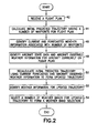
- the process begins by receiving a flight plan (operation 42).
- the process calculates an initial predicted trajectory having a number of waypoints for the flight plan (operation 44).
- the process identifies current and forecasted weather information associated with those waypoints (operation 46).
- the process identifies aircraft state data and aircraft observed weather information for an aircraft currently on the flight plan (operation 48).
- the process recalculates the initial predicted trajectory using the current and forecasted weather information and the aircraft observed weather information to form an updated trajectory (operation 50).
- the process identifies weather information for the updated trajectory (operation 52).
- the process selects a number of weather bands for the updated trajectory to form a weather band selection (operation 54).
- the weather band selection is then included in an uplinked weather report.
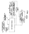
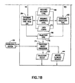
- FIG. 3 shows a ground-based system for receiving a flight plan/route message from a ground source or downlinked from an aircraft, updating the flight plan/route in that message based at least in part on weather information, and then uplinking a message containing the updated flight plan/route in accordance with one embodiment of the invention.
- the process or methodology begins with receiving a flight information message 56 from an aircraft or a ground source (e.g., an operations center).
- An aircraft or an operations center can transmit the flight plan/route in a variety of formats using a variety of methods.
- a flight plan/route message can be transmitted from an aircraft via ACARS, ATN or some other aircraft datalink technology (e.g., broadband satellite IP).
- the message can be transmitted and received in any unique format specified by the user (e.g., an Aeronautical Operational Control datalink message type) or in a standardized ground messaging format (e.g., Type B).
- the ground-based system seen in FIG. 3 optionally comprises a flight information message manager 58, which is a processor that receives an incoming flight information message 56.
- the flight information message manager 58 may be included for the purpose of optimizing the creation of a flight object, which is a generic container comprising a multiplicity of fields containing flight information, such as elements of flight plans, flight routes, flight trajectories, etc.
- the flight object may also contain associated aircraft state data such as weight, center of gravity, fuel remaining, etc. If configured, the flight information message manager 58 would process the flight information and pass the flight plan/route to the flight plan/route processor 60. If the flight information message manager 58 is not included in the configuration, the flight plan/route message would be passed directly to the flight plan/route processor 60.
- the flight plan/route processor 60 effectively converts (by decoding and translation) the flight plan/route information contained in the incoming message into a flight plan/route comprising a list of waypoints and associated flight information.
- the elements of the decoded and translated flight plan/route are stored in fields of the flight object, where they are available for use by the flight plan/route processor 60 and a flight trajectory predictor 64.
- the flight object may reside in a separate processor that manages the flight object.
- the flight plan/route processor 60 after the list of waypoints representing the flight plan/route has been derived by the flight plan/route processor 60, it sends a message to the flight trajectory predictor 64 (or other subscriber-operated processor) informing the latter that the flight plan/route is available for processing.
- the flight plan/route processor 60 sends the flight object to the flight trajectory predictor or other subscriber-operated processor. In this alternative example, no message need be sent informing the subscriber that the flight object is ready for retrieval.
- the flight trajectory predictor 64 (which is also a processor) retrieves the sequence of waypoints making up the flight plan/route from the flight object and then calculates an updated predicted flight trajectory based on the flight plan/route, the original flight trajectory, the aircraft type and how it is equipped, and current and/or forecast environmental conditions.
- a system and method for generating a flight trajectory prediction is disclosed in U.S. Patent Application Serial. No. 13/250352 entitled "Flight Trajectory Prediction with Application of Environmental Conditions". Further details regarding the system and method of U.S. Patent Application Ser. No. 13/250352 are provided in a self-contained section at the end of this disclosure.
- the flight trajectory predictor 64 may incorporate or communicate with a dynamic weather band processor of the type previously described with reference to FIG. 1 . That dynamic weather band processor retrieves current and forecasted weather information associated with the original flight trajectory from a weather database 66. The flight trajectory predictor 64 also identifies aircraft state data and aircraft-observed weather information for the identified aircraft currently flying in accordance with the received flight plan/route. Next, the flight trajectory predictor 64 recalculates the original flight trajectory using the current and forecasted weather information and the aircraft-observed weather information to create an updated predicted flight trajectory with selected weather bands in the flight object.
- That dynamic weather band processor retrieves current and forecasted weather information associated with the original flight trajectory from a weather database 66. The flight trajectory predictor 64 also identifies aircraft state data and aircraft-observed weather information for the identified aircraft currently flying in accordance with the received flight plan/route. Next, the flight trajectory predictor 64 recalculates the original flight trajectory using the current and forecasted weather information and the aircraft-observed weather information to create an updated
- the flight trajectory predictor 64 also causes the dynamic weather band processor (not shown in FIG. 3 ) to select current and forecasted weather information associated with the updated predicted flight trajectory from weather database 66 and then send the selected information to a message constructor 68, as indicated by the dashed arrow in FIG. 3 . More specifically, environmental information, an aircraft identifier, security information and the positions corresponding to the environmental information go directly from the weather database 66 to the message constructor 68 for inclusion in a environmental information transmission.
- flight trajectory predictor 64 can add and/or delete waypoints to the flight plan/route that is stored in the flight object, thereby creating a updated flight plan/route.
- the flight trajectory predictor 64 then sends a message to the flight plan/route processor 60 informing the latter that the updated predicted flight trajectory and new flight plan/route are available for use.
- the flight plan/route processor 60 retrieves the list of waypoints in the flight object representing the updated flight plan/route and uses that processed list of waypoints to construct a payload for inclusion in a flight plan/route message for transmission.
- the flight trajectory predictor 64 can send the flight object to the flight plan/route processor 60.
- the flight plan/route processor 60 Upon completion of this process, the flight plan/route processor 60 sets a flag or sends a message to message constructor 68 indicating that the new flight plan/route and/or trajectory with selected weather bands are ready for transmission (i.e., uplinking). In another example, flight plan/route processor 60 accesses the latest updated flight plan/route in the flight object and determines an update was made by a subscriber and proceeds to process the updated information.
- the message constructor 68 can construct a flight plan/route message with or without a weather update message.
- the message constructor 68 first constructs a message header and then constructs a message comprising that header, the flight plan/route payload received from the flight plan/route processor 60 and a cyclic redundancy check.
- the message is constructed in a message format specified by the message user in accordance with a dynamically settable user configuration stored in a user preferences database.
- This user configuration specifies which functions or processes are running in parallel, and also defines connections to receive and transmit the data from the processors or databases shown in FIG. 3 .
- the user configuration also specifies the behavior of the application.
- the user message format generally pertains to the order and type of data and usually does not encompass the behavior of the application.
- the user message format is hard coded in the message constructor's logic or read from a dynamically settable user configuration required by the end user(s). Alternatively, if the user configuration is absent or unavailable, the system dynamically determines how to format the message based on the origin of the request, the type of information, the aircraft type, the airline operating the aircraft or other information. In either case, the message constructor 68 sends the constructed message to a transmitter (not shown) that will transmit the message to the proper address(es).
- the message constructor 68 takes selected weather information from the weather database 66 and constructs an outgoing message for the end user(s) in a specified user message format. As part of the message construction process, the message constructor 68 encodes the weather information received from the weather database 66. In the case of a weather update message uplinked to an aircraft, the weather update is reviewed and accepted by the flight crew and then autoloaded into the flight management computer.
- the message constructor 68 takes the payload data representing the updated flight plan/route from the flight plan/route processor 60 and constructs an outgoing message for the end user(s) in a specified user message format.
- the updated flight plan/route message uplinked to an aircraft the updated flight plan/route is reviewed and accepted by the flight crew and then the flight crew must contact Air Traffic Control to request clearance for the updated flight path.
- the flight plan/route processor 60 receives an aircraft flight plan/route message 56 and other flight information 78 from a flight information message manager 58.
- the flight plan/route processor 60 also retrieves a user configuration 80 and a user message format 82 from a user preferences database. Then the flight plan/route processor 60 performs the functions of decoding and translating the incoming flight plan/route message, the result including a list of waypoints and associated flight information suitable for use in trajectory calculations and weather information processing as previously described.
- a new trajectory may be calculated by the trajectory predictor 64 which provides direct-to routings to downstream waypoints in the current flight plan/route, eliminating inefficient dog-legs in the en route phase of flight.
- the flight trajectory prediction processor may be programmed to take into account weather and air traffic control status (e.g., traffic sequence and flow and airspace constraints).
- the flight plan/route processor 60 After a new trajectory has been calculated by the trajectory predictor 64, the flight plan/route processor 60 also performs the functions of translating and encoding an updated list of waypoints to construct a payload in a format suitable for inclusion in an updated flight plan/route message.
- the flight plan/route processor 60 utilizes the same methodology for processing an incoming aircraft message and an incoming ground message. However, while the methodology is the same, the conditions applied during the respective processes vary. The conditions may be modified through a dynamically settable user configuration or hard-coded into the logic. The general principle is that in whatever user message format the flight plan/route data is received, it needs to be decoded and translated before it can be used to determine an updated flight plan/route with or without environmental information.
- an incoming message is decoded by decoder 70 of the flight plan/route processor 60.
- the decoding scheme is a function of the user configuration and user message format.
- the decoder 70 parses the message by separating the flight plan/route from other parts of the message. If the message was encrypted, then the decoder 70 will execute a second decoding stage in which the encrypted flight plan/route is decrypted.
- the decoder 70 pulls (i.e., parses) data out of the flight plan/route and maps that data into applicable attribute fields of the flight object.
- the decoder 70 converts user defined points such as latitude/longitude, floating waypoints, place bearing distance, or along track waypoints, intersections and airways and flight procedures into associated waypoints by internal computations or by reference to a navigation database (item 62 in FIG. 3 ), which stores navigation information pertaining to waypoints, airports, airways, and procedures and customer information. Information retrieved from the navigation database is again stored in the flight object.
- a navigation database (item 62 in FIG. 3 ), which stores navigation information pertaining to waypoints, airports, airways, and procedures and customer information. Information retrieved from the navigation database is again stored in the flight object.
- the navigation information of greatest complexity is airways and flight procedures (e.g., departure and arrival procedures).
- the decoder 70 uses that information to do a look up in the navigation database to query for additional data. For example, assume that the flight plan/route message identifies a standard instrument departure (SID) procedure, which consists of a number of waypoints or fixes and a climb profile.
- SID standard instrument departure
- the decoder 70 uses the identified SID to query information in the navigation database.
- the navigation database query would return a listing of waypoints and possibly other associated data. All of the returned waypoints would be stored in the flight object.
- An incoming message translator 72 of the flight plan/route processor 60 then continues the process by translating the waypoints stored in the flight object into a list of waypoints representing a proper flight plan/route. As part of this process, the incoming message translator 72 determines which of these waypoints are applicable and in which order. The correct ordering of the waypoints is determined from the content of the message and adaptive logic guidelines. For example, transition types indicating one method of movement from one point to the next can be derived from the message content.
- a logic guideline may include, but is not limited to, the required security, FMC operations and limitations, aircraft state, current or predicted flight information, the aircraft type and/or the airline operating the aircraft.
- duplicate or extraneous waypoints, or waypoints that have been passed by the aircraft since the time when the flight plan/route message was received are generally not included in the final list of waypoints.
- the end result is a listing of waypoints representing a proper flight plan/route, stored in the flight object.
- the incoming message translator 72 of the flight plan/route processor 60 sets a flag or sends a message to the flight trajectory predictor 64 (or other subscriber-operated processor) informing the latter that the flight plan/route is available in the flight object for processing.
- the flight plan/route processor 60 can send the flight object to the flight trajectory predictor 64 (or other subscriber-operated processor).
- flight trajectory predictor 64 can add, reorder or delete waypoints to the flight plan/route that is stored in the flight object, thereby creating a new flight plan/route.
- the flight trajectory predictor 64 then sends a message to an outgoing message translator 74 of the flight plan/route processor 60 informing the outgoing message translator that the updated predicted flight trajectory and new flight plan/route are available for use.
- the outgoing message translator 74 combines the updated list of waypoints in the flight object to form a new flight plan/route by referring again to the navigation database (not shown in FIG. 4 ).
- the outgoing message translator 74 translates sequences of waypoints into airways and flight procedures that are added to the flight object.
- the outgoing message translator 74 takes into account the aircraft type, aircraft state data and the current location of the aircraft. For example, an identifier may identify multiple waypoints at different locations, and the outgoing message translator 74 will determine which of those waypoints was intended based on the present location of the aircraft and the flight intent trajectory information.
- the translated waypoint fields in the flight object are then encoded by an outgoing message encoder 76 of the flight plan/route processor 60. More specifically, the encoder 76 parses the translated list of waypoints in the flight object and then encodes the parsed data to construct a payload for inclusion in a flight plan/route message to be uplinked. More specifically, the encoder 76 puts the parsed list of waypoints into the order required by a user-specified flight plan/route message format.
- the outgoing message encoder 76 will also identify the transition types (e.g., direct to or via). The transition type is crucial to the definition of the encoded outgoing message.
- the encoder 76 can either set a flag or send a message to message constructor 68 indicating that the new flight plan/route payload is ready for transmission (i.e., uplinking), or send updated flight plan/route payload directly to message constructor 68.
- the message constructor 68 then assembles all of the message components and formats the message for the end user.
- the aircraft identifier and airline identifier in the flight information received by the flight plan/route processor 60 dictate what incoming message decoding/translating scheme should be used or the scheme can be declared in the user format.
- An instruction regarding what translating/encoding scheme should be used is sent to the outgoing message translator/encoder, as indicated by the arrow connecting blocks 72 and 74 in FIG. 4 .
- the outgoing message translating/encoding scheme applied by the flight plan/route processor 60 will be a function of the applied decoding/translating scheme. These schemes take the form of subroutines retrieved from processor memory and executed by the flight plan/route processor 60.
- an aircraft flight message is received, such as:
- this specific exemplary flight message The meaning and ordering of particular symbols and characters appearing in this specific exemplary flight message are dictated by the applicable user specifications and will be different for other flight messages constructed in accordance with different user specifications. Therefore the detailed discussion of this specific exemplary message is not intended to limit the scope of the invention, in which the flight plan/route processor can be programmed to handle flight messages in different formats.
- a single period means Via Transition and a double period means Direct To.
- the route format of this exemplary message is not useable for trajectory and weather calculations. It must be decoded and translated.
- the conditions applied during decode and translation of an incoming message vary per aircraft type, the aircraft state data which was derived from the flight information, or associated data derived from the route data itself (e.g., leg types).
- the route must be decoded and translated into a waypoint to waypoint type of route with the associated data (e.g., known leg types, altitude constraints, etc.). Therefore, an additional operation is required in the decoding operation due to the specification of the route consisting of more than waypoint to waypoint routing (i.e., the route contains airways, a STAR, etc.).
- the SID12 would be expanded to WPTA, WPTB, WPTC, ABC and WPTY.
- the jet airway J12 would expand to ABC, DEF, GHI, and WPT1.
- the victor airway V140 would consist of WPT1, WPT7, WPT8, and WPT9.
- the transition TRANS would consist of only the fix TRANS.
- the STAR2 terminal arrival route identifies the arrival route into KLAX, which consists of waypoints WPT15, WPT16, WPT17, WPT18 and WPT22.
- the final decode of the aircraft message would look like the following list: KSEA RWY04, WPTA, WPTB, WPTC, ABC, WPTY, ABC, ABC, DEF, GHI, WPT1, WPT1, WPT1, WPT7, WPT8, WPT9, WPT9, TRANS, WPT15, WPT16, WPT17, WPT18, WPT22, and KLAX RWY18.
- the decoded message is then translated. Translation may include the deletion of duplicate or extraneous waypoints or waypoints that have been passed by the aircraft since the time when the flight plan/route message was received. At the completion of this operation, the incoming flight plan/route is processed and the list of waypoints may be used for trajectory, weather or other processing.
- the decoded and translated flight plan/route might look like what follows, again dependent on the conditions, yet representative of the actual flight: KSEA RWY04, WPTA, WPTB, WPTC, ABC, DEF, GHI, WPT1, WPT7, WPT8, WPT9, TRANS, WPT15, WPT16, WPT17, WPT18, WPT22, and KLAX RWY18.
- the next operation is to translate and encode the trajectory or updated flight plan/route and/or the selected weather bands into an outgoing message for transmission to a user or users.
- the process of translating the flight plan/route is determined by a user configuration (80 in FIG. 4 ) or hard-coded logic and could involve correlating the list of waypoints to standard instrument departures, airways, standard terminal arrival routes, approach procedures, etc. In another example with a different configuration, the translator may simply output a list of waypoints.
- the outgoing encoder constructs a payload for a flight plan/route uplink message in accordance with the same encoding used to encode the original received message.
- the system disclosed herein generates a predicted flight trajectory using a combination of aircraft state data, flight information, environmental information, historical data or derived flight information from aircraft messaging which can be used for the transmission of environmental data.
- Flight information necessary to compute the predicted trajectory (such as waypoints, their locations, estimated time of arrivals (ETAs) at those waypoints, and fuel remaining) is extracted and used, along with aircraft state data, messaging, and their histories, to calculate and derive the predicted trajectory.
- the predicted trajectory includes pseudo-waypoints at flight transitions not readily available in the flight information and the environmental conditions at all waypoint (including pseudo-waypoint) locations. Thereafter the generated trajectory prediction is assigned confidence and accuracy levels based on fidelity, merit or reliability.
- the process/method to create a predicted trajectory(s) for a flight begins with receiving a flight information message.
- the flight information message may be from an aircraft to a ground station, from a ground source to a ground station, or from an alternate source to an unspecified location (including both source and trajectory solution on airborne platforms, not necessarily the same platform).
- An aircraft can downlink the flight information in a variety of formats using a variety of methods. It can be transmitted from an aircraft via ACARS, ATN or some other aircraft datalink technology (e.g., broadband satellite IP). From ground sources, the message can be transmitted and received in any unique format specified by the user (e.g., an AOC) or as standardized ground messaging formats (e.g., Type B message format). If used in an airborne system, this process/method could be realized in software or hardware form, and use either air-to-air datalink communications paths or on-board networking, or receive inputs directly from an on-board flight management computer.
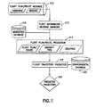
- the system seen in FIG. 5 optionally comprises a flight information message manager 112, which is a processor that receives an incoming flight information message 110.
- the flight information message manager 112 may be included for the purpose of optimizing the creation of a flight object, which is a generic container comprising a multiplicity of fields containing flight information, such as elements of flight plans, flight routes, flight trajectories, etc.
- the flight object may also contain associated aircraft state data such as weight, center of gravity, fuel remaining, etc. If configured, the flight information message manager 112 would process the flight information and pass the flight plan/route to a flight plan/route processor 114. If the flight information message manager 112 is not included in the configuration, the flight plan/route message 110 would be passed directly to the flight plan/route processor 114 for use in creating a flight object.
- the flight plan/route processor 114 uses data retrieved from a navigation database 116 to convert (e.g., by decoding and translation) flight plan/route information contained in the incoming message 110 into a flight plan/route comprising a list of waypoints and associated flight information.
- the elements of the decoded and translated flight plan/route are stored in fields of the flight object (along with aircraft type and equipage), where they are available for use by the flight plan/route processor 114 and a flight trajectory predictor 118.
- the flight object may reside in a separate processor that manages the flight object.
- the flight plan/route processor 114 After the list of waypoints representing the flight plan/route has been derived by the flight plan/route processor 114, it sends a message to the flight trajectory predictor 118 (or other processor) informing the latter that the flight plan/route is available for processing. Alternatively, the flight plan/route processor 114 sends the flight object to the flight trajectory predictor 118. In this alternative example, no message need be sent informing the user that the flight object is ready for retrieval.
- the flight trajectory predictor 118 (which is also a processor) receives the flight object containing a list of waypoints making up a flight plan/route from the flight plan/route processor 114 and then calculates an updated predicted flight trajectory 122 based on that flight plan/route, an original flight trajectory (if available), the aircraft type and how it is equipped, current and/or forecast environmental conditions retrieved from an environmental database 120, and other information described in more detail below.
- the flight trajectory predictor 118 can receive a flight object from any process.
- the flight trajectory predictor 118 performs the function of creating a complete trajectory or updating an existing one using the most current information received from flight information messages for that flight, adding pseudo-waypoints at flight transitions not explicit in the flight information and selecting the environmental conditions as well as calculating other metadata associated with all waypoint (and pseudo-waypoint) locations.
- the trajectory prediction process can start at any point in any phase of flight, and modifies its process methods/components as appropriate to the aircraft state and flight information available in messages, known to be available about that phase, known to be available about a future phase, and/or provided by a knowledge system.
- Flight information available through messaging varies based on the source, aircraft type, configuration parameters, flight state and phase, and other conditions, and trajectory prediction calculations needed may differ by source, aircraft type, state, and phase of flight as well as user configuration information provided.
- the flight trajectory predictor may receive information on the data source through the user configuration or a knowledge system, which can aid the process in determining which methods/components to use in calculating the trajectory given known information about a flight. All of this information is maintained in a trajectory object (not shown in FIG. 5 ).
- the flight trajectory predictor 118 adds pseudo-waypoints that are not included in the flight plan/route, if indicated to do so by a user configuration or by the required accuracy level.
- Pseudo-waypoints are points in the trajectory which are not explicitly part of the actual route, but identify where environmental events or flight maneuvers occur, such as speed, altitude, or heading changes.
- Pseudo-waypoints are also used where constraints must be met, such as a speed or an altitude constraint. Pseudo-waypoints may also come in pairs for the start and end of a transition, as there must be a gradual change for the maneuver planned.
- the flight trajectory predictor 118 uses the same pseudo-waypoints in its trajectory as the source's flight plan system uses; however the flight trajectory predictor 118 may introduce more pseudo-waypoints not included in the source's trajectory prediction to improve predicted trajectory accuracy. Some examples of reasons additional pseudo-waypoints may be included by the flight trajectory predictor 118 are environmental conditions, air traffic, temporary flight rules, flight conventions, standard flight practices, or user configuration declarations.
- the flight trajectory predictor 118 adds environmental data and other metadata for each waypoint and pseudo-waypoint in the trajectory object.
- each waypoint and pseudo-waypoint in the trajectory object constructed by the flight trajectory predictor would have an associated position location (latitude, longitude), altitude, phase of flight, estimated time of arrival to the flight destination, fuel remaining, environmental conditions, and metadata used for calculating trajectory data (segment distances, speeds, ETAs at waypoints, etc.).
- the trajectory predictions are recalculated. This is a continual iterative process. It is an iterative process because after the environmental data is applied; the trajectory will shift accordingly and new environmental points may have been chosen.
- the trajectory prediction is at its highest refinement for the given information. Again, this process can be configured to be either dynamic or static.
- the predicted trajectory(s) 122 is the output of the flight trajectory predictor 118, and can be used as the basis for other calculations, for system or flight status checking or environmental uplink messaging, as a few examples. A system and method for uplinking environmental messages is described above with reference to FIGS. 1-4 .
- the predicted trajectory is stored in the flight object.
- the flight object 124 comprises a flight path or route derived after decoding and translation of a set of flight information by the flight information message manager and/or the flight plan/route processor.
- the flight object 124 may also comprise the aircraft type, aircraft state data, the source of the information and metadata.
- the flight object 124 may further comprise an incomplete flight trajectory.
- the flight trajectory predictor 118 can adjust its process based on a user configuration 126, such as setting the trajectory prediction process to include or exclude certain components (components for flight information decoding and translation are examples, as are components specific to calculation methods), past flight histories, or available data.
- the flight trajectory predictor 118 receives flight object information 124 and can also accept user configuration data 126 to adjust how the predicted trajectory 122 is to be generated.
- a trajectory object manager 128 creates or updates a trajectory object template resembling the form the source uses with the flight information that is currently available or which can be derived.
- the trajectory object 132 may be created when the aircraft is at different phases of flight, and the phase of flight can help the knowledge system 130 (available globally inside of trajectory object manager 128) determine the methods/components or order of components needed to calculate the trajectory.
- the partially completed trajectory object 132 is then output to a trajectory predictions processor 134.
- the trajectory object manager 128 can create a missing elements request 144.
- This request may include a request for flight information different than currently available or a request for more recent flight information than the current set.
- This request 144 can be output to a processor, system log, or flight messaging source.
- a trajectory object 132 has all of the information needed to calculate a full predicted trajectory, the trajectory object is output to the trajectory predictions processor 134 and is also saved in the embedded knowledge system 130.
- Trajectory object manager function status options are generated from knowledge system 130 and provide, for example, trajectory log modeling, function health "self-situational awareness," and mechanisms to allow for detection of non-normal and abnormal trajectory generation with alert feedback (i.e., status/alerts message 146) outside of the flight trajectory predictor 118, which triggers reprocess (or modified reprocess) opportunities either in real-time (self-healing) or for post-flight analyses.
- the status/alerts message 146 could also be the result of a combination of security/health features providing the input to and triggers for process protection, attack detection, and restoration of options which can satisfy information assurance mandates.
- the trajectory object 132 which the trajectory object manager 128 creates or modifies contains all the trajectory elements obtainable using the available flight information.
- the trajectory object 132 is passed to the trajectory predictions processor 134, which uses the information in that trajectory object to compute the metadata needed to create (i.e., calculate) a complete trajectory (operation 138) and apply environmental data (operation 136) to produce a predicted trajectory 122 for the particular flight.
- the trajectory predictions processor 134 also calculates the levels of confidence and accuracy of the predicted trajectory (operation 142).
- the trajectory predictions processor 134 takes a trajectory object 132 and calculates the metadata for all the trajectory points contained in it.
- Metadata can include information that is associated with the trajectory which the trajectory object manager 128 does not extract, calculate, or derive. Examples of metadata for a trajectory include the segment distances and headings, altitudes, ETAs, and fuel quantities for waypoints and pseudo-waypoints.
- the specific metadata to be included (calculated or not) is determined by the user configuration 126. Some points may have already been calculated or received metadata (within the trajectory object manager 128), which may be used instead of recalculating their values, but for points without metadata, or those which have been modified, the trajectory predictions processor 134 performs a series of calculations to complete the trajectory prediction.
- the trajectory object holds a complete trajectory which resembles that of the source of flight information, and the trajectory predictions processor 134 is able now to apply environmental data along the trajectory (operation 136).
- the environmental conditions for the points in the predicted trajectory can be retrieved from the environmental database 120.
- the applied environmental conditions affect the performance of the aircraft in flight, especially the speed economy selection of the aircraft and position of pseudo-waypoints. Since the pseudo-waypoints are not fixed in space, their locations may need to be adjusted after the application of environmental data, as well as other flight elements, including but not limited to fuel quantities, altitudes, and ETAs for each of the trajectory waypoints.
- FIG. 6 shows how the trajectory predictions processor 134 first takes in a trajectory object 132 and then calculates the metadata for it, creating a complete trajectory (operation 138). The complete trajectory is needed for the processor to identify what environmental data to pull from the environmental database 120. After the environmental conditions have been applied (operation 136), the trajectory must be recalculated (operation 138) to update its derived pseudo-waypoints, and also recalculate the metadata which would be affected by the changes. The recalculations of the trajectory prediction with reapplied environmental conditions are continued until a determination (operation 140) is made that the predicted trajectory does not require any more additional application of environmental conditions.
- the trajectory predictions processor 134 calculates a confidence level and accuracy level for the predicted trajectory based on the quality of information extracted, calculated, and derived (operation 142). These levels may be evaluated for separate sections of the trajectory or for the predicted trajectory as a whole.
- the level of predicted accuracy is based on the number of and sources of the specific information, time, distance or flight phase. For example, if flight information has to be derived to calculate a trajectory, because the aircraft has not directly transmitted such information, the level of accuracy of the predicted trajectory may be reduced. This reduction in accuracy may influence the "confidence".
- a reduction in confidence may be used for triggers of other applications to perhaps increase aircraft messaging or request additional information directly.
- the flight trajectory predictor 118 has a predicted trajectory 122 with associated confidence and accuracy ratings which it may output, in whole or in part, for use by follow-on applications, such as a message constructor (not shown in FIG. 6 ).
- the predicted trajectory 122 with associated confidence and accuracy levels is also stored in the knowledge system 130.
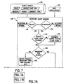
- FIG. 7 An example of a trajectory object manager process is shown in FIG. 7 , which consists of FIGS. 7A and 7B .
- system security interface options are identified for input validity (operation 150) and access authentication (operation 152), as are required for any networked system, and would be part of a federated/distributed security scheme for all functions/subsystems/devices of the system employing the flight trajectory predictor. If the input is invalid or access is not authorized, the trajectory object manager selects a rejection option.
- the trajectory object manager 128 may receive information about the source of the flight Information and the flight phase; however, if not provided, the trajectory object manager 128 determines the source and flight phase (operation 156 in FIG. 7A ) from the information that is available in the flight object 124. For example, assume that the trajectory object manager 128 receives a flight object 124 from the flight plan/route processor (item 114 in FIG. 5 ) which contains an aircraft's flight plan, current state data, and tail ID. The source information and aircraft type can be determined from the tail ID according to the user configuration 126. The flight phase can be determined using the state data with the flight plan, comparing the current altitude with the flight plan's cruise altitude and flight schedule, if all are available.
- the trajectory object manager 128 also identifies the necessary minimum process components needed to build a trajectory prediction that resembles that of the source, desired output trajectory, or the process components to be included or deleted according to user configuration instructions.
- the user configuration 126 may contain specific rules, conventions, or practices to which the trajectory must adhere.
- the user configuration 126 may contain a default trajectory format for new or unfamiliar sources; or it may follow rules to infer trajectory types based on flight information content, such as determining whether the source is an aircraft or a ground system.
- the knowledge system 130 (see FIG. 7B ) records the trajectory object manager's results for future reference and subsequent use for improving trajectory predictions for other flights.
- the trajectory object manager determines if there is a defined trajectory type for that data (operation 158 in FIG. 7A ). If the trajectory type is already defined for the source and flight phase provided, then that type will be used (operation 160 in FIG. 7B ) in conjunction with any user configuration settings 166 applied. If there is no defined trajectory type, the trajectory object manager identifies trajectory types that are possible to create with the available information (operation 162 in FIG. 7A ).
- the knowledge system 130 may use heuristics, correlation, learning algorithms, accumulated evidence, existing flight object information, state data/flight phase, and other information to discover and select criteria for possible trajectory types.
- the knowledge system 130 is capable of updating itself with new data, after that data has been tested for validity and authentication. From the list, a trajectory type 172 is chosen (operation 164 in FIG. 7B ) which also meets the user configurations, and the required accuracy and confidence levels (items 168 and 170 in FIG. 7B ) for the trajectory type 172 are recorded. Status/alerts are associated with the trajectory object 132 or predicted trajectory 122. The trajectory type 172 is then sent with the flight information to a trajectory object processor 174, which creates or updates a trajectory object 132 for the particular flight.
- FIG. 8 The process for calculating a trajectory with the known information in accordance with one arrangement is shown in FIG. 8 , which consists of FIGS. 8A and 8B .
- the trajectory object processor 174 determines whether a trajectory can be calculated from the available information (operation 176). This is determined with reference to what specific level of information a user has requested. If all the necessary data for a trajectory is included in the flight object 124, then a trajectory object 132 (shown in FIG. 8B ) is created immediately and output to the trajectory predictions processor (item 134 in FIG. 6 ). If in operation 176 the trajectory object processor 174 determines there is insufficient data to create a trajectory of the specified trajectory type, elements of the trajectory may possibly be derived.
- the trajectory object processor 174 determines whether derivations have been done previously (operation 178 in FIG. 8A ). If not, then a derivation method is selected. There are many possible derivation methods for various trajectory elements; some use different sets of flight information, or larger sets of information, and some can be more accurate than others. Based on the available flight information, the required confidence and accuracy levels, and the trajectory type needed, the trajectory object processor 174 determines (operation 190 in FIG. 8B ) which methods to use in order to derive the needed information for the trajectory object, and at the needed level of confidence and/or accuracy. The trajectory object processor can adjust its calculations depending on the information that is available in a flight, as there can be multiple ways to calculate or derive trajectory elements.
- FIG. 8B illustrates two methods (Method 1 and Method 2) that can be chosen for deriving the trajectory elements based on known information.
- Method 1 contains more steps than Method 2.
- some elements are extracted directly (operation 192) and others are calculated from the available flight information (operation 194).
- missing elements are derived from the available flight information (operation 196). While both methods have a "Derive Elements" block, the derivations used may be different between Method 1 and Method 2.
- Trajectory elements are derived using a combination of conversion formulas, equipage, airspace and aircraft constraints, the knowledge system, and rules of best practice with information gained from current and/or past flight information messages. For cases where more pertinent information is known for the flight, a more accurate derivation may be possible.
- Operation 190 uses one or more of a knowledge system, extraction, calculation, and derivation to ascertain the trajectory elements that result in a predicted trajectory which best meets the required confidence and accuracy levels given the known information. When data is missing for the most preferred derivation method to be used for a necessary trajectory element, then an alternate method must be used to generate a prediction for that element. While FIG. 8B shows only two possible options for computing the trajectory elements, there may be many options when there are multiple elements with multiple methods of prediction.
- a third example would be using a system of linear equations to determine the position of specific waypoints or all pseudo-waypoints based on previous flight histories.
- Another option employed by trajectory object processor 174 is to use displacement vectors to determine the needed elements.
- operation 178 is repeated. This time, because a derivation has been done previously, the process moves to operation 180, which determines whether trajectory retrieval has been done previously. If trajectory retrieval has not been done previously, the process can retrieve other trajectory objects from the knowledge system (operation 182), such as previous flight histories for that particular aircraft, and infer trajectory elements from current versus previous flight performance (operation 184) or from aircraft operating in proximity.
- the flights used to generate trajectory objects by the knowledge system can be selected from flights flown in similar conditions; examples may include flights flown within a time horizon, or in similar environmental conditions, or in same time period, or those with the same flight path segments.
- the top of descent is unknown; however, it can be determined accurately from time in the aircraft messaging when in or near descent. So if a top of descent for a trajectory needs to be predicted for a flight, the data from flights of the same aircraft type with similar gross weight, speed, and flying in similar environmental conditions can be gathered and analyzed. Then a top of descent position or some other trajectory elements which may be used to determine the top of descent position, such as a descent flight path angle, may be estimated from interpolation of that data to match the current aircraft's conditions.
- trajectory elements obtained from the hysteresis analysis do not directly contribute to the information needed to calculate a trajectory object, they may allow new information to be derived. Therefore if a trajectory is still unable to be calculated with the accumulated information, the process determines whether more information can be extracted or derived (operation 186 in FIG. 8B ). If the determination is affirmative, another iteration of derivations can be completed to derive new trajectory elements.
- trajectory object manager 128 determines that more information cannot be extracted or derived (operation 186)
- a request for flight information is constructed (operation 188).
- a missing elements request 144 is then outputted to a processor, system log, or flight messaging source, as previously described.
- the cruise altitude, climb speed, cruise speed, etc. are needed to predict a gate-to-gate flight trajectory.
- the minimum required data set is dependent on the flight phase and requested level of accuracy and/or confidence. If the user requests the most accurate trajectory prediction, the minimum information is not enough.
- the level of accuracy and/or confidence requested by a user dictates what additional information beyond the minimum is needed. This is captured by the user configuration 126 (see FIG. 6 ). For example, a user configuration might specify that an output to User X must have a confidence level Y and/or an accuracy level Z. From Y or Z, it is known that the basic set of information to compute a trajectory is D 1 , D 2 , ...
- the trajectory object processor 174 (see FIG. 8 ) tries to obtain the missing information by deriving, calculating, extracting and requesting. If it cannot obtain the missing information, the trajectory predictions processor 134 (see FIG. 6 ) will still output a predicted flight trajectory 122 because the minimum data set was available, but the accuracy level and confidence level calculated by the trajectory predictions processor 134 would show a lower level than what was requested, and the user would then know the requirement had not been met. In accordance with one arrangement, the output is always a trajectory prediction, unless the minimum information necessary is not available.
- the desired output is basic trajectory prediction from the available flight information and/or a trajectory prediction equal to the requested level of accuracy and/or confidence. This means that multiple outputs for various users at varying levels of confidence and accuracy can be generated.
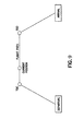
- FIG. 9 An illustration of an idealized trajectory profile is shown in FIG. 9 .
- Two pseudo-waypoints that are necessary to define the vertical profile of the trajectory are the top of climb (TOC) and top of descent (TOD).
- TOC top of climb
- TOD top of descent
- a list of basic trajectory elements which may be needed to generate a baseline trajectory with top of climb and top of descent as seen in FIG. 9 would be the Origin, Destination, Cruise Altitude, Climb Speed, Cruise Speed, and Descent Speed. In some instances these could all be reported in a flight plan; however, often some or all of these elements must be calculated or derived using other available information.
- the content of the flight information can vary with different data sources, so the trajectory object manager must be able to adjust its method for obtaining trajectory elements based on the available information.
- elements may need to be derived using information from a combination of different sets of flight information messages, and so the ability to use current flight information with stored past flight information history is required.
- more details and pseudo-waypoints may need to be calculated, requiring different sets of trajectory elements to be known. Examples of these could be pseudo-waypoints that define transitions in the trajectory for speed or altitude constraints that must be met in the climb or descent phases or a step climb or step down during the enroute phase.
- the aircraft is in the enroute phase of flight. Therefore the top of climb has already been passed, and only the top of descent needs to be derived.
- the top of descent identifies where the aircraft will transition from flying at its cruise altitude to a descent to the destination. The following is an example of how a top of descent may be derived from flight information messaging.
- a flight information message is received with the status that the aircraft is a specified time away from its top of descent along with the timestamp indicating when that message was sent.
- the method/process uses the current speed of the aircraft, which has been derived from flight information (segment speeds, or an alternate combination of trajectory predictions processor functions), and the aircraft position, extracted from flight information to locate the predicted top of descent (TOD in FIG. 9 ) position at the specified time in the future.
- Another advantageous arrangement further improves the accuracy of the trajectory prediction by improving the derivation technique itself. For instance, there is error in the derivation of the speed calculations currently used which is due in part to the timestamp in the message received. To reduce error in the top of descent calculations using the derived speed, the speed used must be calculated in the same way as the source's reported speed. This means adjusting the speed to incorporate environmental conditions used by the source. As the flight information message may be routed through multiple relays, the timestamp of the message may be the time it was sent from one of the relays, not the source. So the flight information should contain a separate element indicating the time when the message was sent independent of the timestamp, in order to identify the aircraft position and predict the time/distance to top of descent.
- trajectory prediction is required before flight information detailing a specified time to top of descent has been received (e.g., before departure)
- an alternative method must be used to estimate the top of descent and then refine it later.
- One approach to these calculations requires a descent path angle or projected rate of descents, which is derived from the aircraft's cruise speed, descent speed and altitude and descent speed constraints into its destination. Calculations can then extrapolate backwards starting from the last waypoint or pseudo-waypoint with a computed or specified altitude (near the destination). Waypoint altitude calculations are continued until the cruise altitude is reached, signifying the top of descent point.
- multiple methods must be available for trajectory calculations, depending on the known flight/trajectory information. The example becomes more complex with an aircraft type that provides minimal flight information.
- trajectory object manager represents just one exemplary arrangement and is not intended to limit the scope of the idea.
- Other arrangements may consult the previous trajectory objects for all derivations to improve confidence levels, as an example of more knowledge system discovery.
- the derivations of waypoint positions could be filtered with known data of other current or past flights from the trajectory log in real time to make accurate flight predictions for a particular aircraft.
- Arrangements employing hysteresis of past flight data in trajectory predictions could be done in two ways.
- One method is to include the additional data in the derivations of the predicted trajectory. This could be done by building a system of equations using all of the available data and calculating a resulting trajectory prediction, such as a pseudo-waypoint location or a speed.
- Another method is to augment the predicted trajectory already derived with interpolation or projections of the aircraft state onto past flight data.
- An example of how a final predicted trajectory could be generated from these is through a weighted combination of the predicted trajectory and a projection which fuses the data sets weighted with respect to their estimated accuracy. So, early in the flight the hysteresis data would be relied on more, but closer to the descent the derived values of the predicted trajectory would be weighted more.
- the trajectory prediction generated from these methods and system is completed without the use of any specific aircraft performance database, using the current flight information received and an independent environmental database.
- This trajectory prediction system also can adapt its output dependent on a static user configuration or dynamically based on the available information or past known flight information.
- This trajectory prediction system also produces a higher accuracy solution due in part to utilizing in situ and forecasted environment data and the techniques used to derive unknown flight data elements.
- the output solution can also include an identifier distinguishing the level of accuracy and/or confidence of the trajectory predictions.
- the system is able to adapt to many different sources, both airborne and ground, and generate predicted trajectories which correlate with the source's format, as opposed to having its own independent format.
- the predicted trajectory solution is dependent on pseudo-waypoints and their locations and metadata. Since the flown flight path and speed is affected by the weather, the pseudo-waypoints can be modified by adding current weather data unavailable to the aircraft's on-board computer.
- making a message available means transmitting the message or storing the message for retrieval.
- the method claims set forth hereinafter should not be construed to require that all operations of the method be performed in alphabetical order or in the order in which they are recited.
Abstract
Description
- The embodiments disclosed hereinafter generally relate to systems and methods for providing a flight plan with or without environmental information to a user. More particularly, the disclosed embodiments relate systems and methods for providing a flight plan with or without environmental information to a user in response to receipt of current flight information.
- Environmental information is used during planning and execution of flight operations. Planning flight operations result in the creation of flight plans. Flight plans are used to document basic information such as departure and arrival points, estimated time en route, various waypoints the aircraft must traverse en route, information pertaining to those waypoints, such as actual or estimated altitude and speed of the aircraft at those waypoints, information relating to legs of the flight between those waypoints, and aircraft predicted performance. This type of flight plan may be used to construct a flight trajectory including the various legs of the flight, which are connected to the various waypoints along the route. This flight trajectory may include a lateral trajectory defined in the horizontal plane and a vertical trajectory defined in the vertical plane. The flight trajectory may also include the element of time across the horizontal and vertical planes.
- Environmental information for the route between the departure gate and arrival gate, including information about forecasted and in-situ weather for the various waypoints along the route, may affect a flight trajectory. For example, if incorrect weather is forecasted for a particular waypoint along the route of the flight plan, certain predictions for the flight path may become inaccurate, such as speed, fuel consumption, and time en route.
- Additionally, revision of a flight plan may include deleting or adding waypoints, modifying the position of waypoints, or modifying the characteristics pertaining to the waypoints or legs between the waypoints, such as aircraft speed, time of arrival at the waypoint, or altitude. The characteristics for various waypoints or legs between waypoints may further include weather bands. A weather band is a collection of environmental information for a specific spatial point, such as a specific altitude or a specific three- or four-dimensional point in space. Environmental information may include but is not limited to factors such as temperature, pressure, noise, air particulates, humidity, turbulence, wind speed, and wind direction.
- Ground operation centers may identify and send weather bands to an aircraft for use in determining how weather may affect flight trajectory calculations. The weather bands identified may be based on current or predicted weather, flight predictions, flight intent or flight plans, or may be default weather bands non-specific to a particular flight trajectory. Actual weather may impact a predicted flight trajectory if the actual weather differs from the predicted weather used to calculate the predicted flight trajectory. Additionally, different factors en route may cause an aircrew to modify the flight plan, and the environmental information from the ground operation center, loaded during preflight, may no longer be accurate or up-to-date for the modified flight plan. Inaccurate or dated environmental information can result in inefficiencies for flight operations, such as an increase in fuel consumption and emissions or delay in flight time, for example.
- It is known for an aircraft to request a new flight plan and/or new environmental information from a ground-based operations center or air traffic controller. The downlinked request may be accompanied or followed by current flight route or flight plan information for that aircraft. The downlinked flight route or flight plan information may consist of such items as: a list of waypoints, instrument departure procedures, arrival and departure transitions, airways, Standard Terminal Arrival Routes, fixes and leg types.
- More generally, flight information can be received from either a ground source or from an aircraft in the form of a flight message. From a ground source, there is no current solution to decode and translate the flight message into a flight plan type of format because each ground source may specify its own unique format and encryption. For flight messages downlinked from an aircraft, there is a known software tool that can be used to parse the flight message, but nothing to decode and translate the flight message. For the uplink, there are no solutions to translate and encode a list of waypoints and other flight information representing a flight plan/route with or without environmental information.
- There is a need for systems and methods for decoding and translating a received flight plan or route and, thereafter, translating and encoding a trajectory or flight plan/route with or without selected environmental information into an outgoing (e.g., uplinked) message for transmission to users. There is a need for a systems and methods to be adaptive to multiple variations of incoming and outgoing flight plan/route formats.
- As used herein, the term "flight plan/route" means a flight plan or a flight route. Although the terms flight plan and flight route usually have different meanings (e.g., a flight plan may specify a cruise altitude, but a route does not and is usually limited to a two-dimensional perspective), sometimes these terms are mistakenly defined as the same. In this disclosure, the term "flight plan/route" is used because the system disclosed herein can handle either, interchangeably and independently.
- Flight plan/route messages transmitted from aircraft and ground sources need to be decoded, translated and encoded for use in processing flight plan, trajectory and environmental messaging solutions. The solution must be adaptive to multiple variations of transmission and multiple formats: aircraft-to-aircraft, aircraft-to-ground, ground-to-aircraft and ground-to-ground communications. The solution must also be adaptive to the multiple variations for uplinking and crosslinking to various users. As an example, the solution would be translated and encoded one way for a particular airplane model and another way for a different airplane model. The solution must consider the end user.
- Using a downlinked flight plan/route message from an aircraft, other flight information (i.e. aircraft type, cruise altitude, planned speed schedule, aircraft state data, airline) and/or navigation database information, the portion of the downlinked message containing the flight plan or route is decoded and translated to construct a ground-based flight route comprising a list of waypoints. The list of waypoints may then be used in calculations performed by a flight trajectory predictor to identify spatially associated environmental information and/or to create an updated flight plan or route (e.g., by adding or changing waypoints in a flight object) and thereafter transmit that information to users. Prior to transmitting any flight plan/route, the flight plan/route waypoints in the updated flight object must be translated and encoded into the required format for inclusion in an outgoing (i.e., uplinked) flight plan/route message.
- One aspect of the invention is a system for processing flight information comprising a flight object, and a flight plan/route processor capable of communicating with a navigation database and the flight object. The flight plan/route processor is programmed to perform the following operations: (a) obtaining a flight plan/route message comprising payload data representing a flight plan/route of an aircraft; (b) parsing the payload data in the obtained flight plan/route message to extract flight information; (c) decoding components of the flight information to derive a list of waypoints and associated flight information; (d) storing the list of waypoints and associated flight information in the flight object; and (e) translating the list of waypoints in the flight object into a list of waypoints suitable for use by a user.
- Another aspect of the inventions is a system for processing flight information comprising: a flight object that stores a list of waypoints associated with a flight plan/route of an aircraft; and a flight plan/route processor capable of communicating with a navigation database and the flight object. The flight plan/route processor is programmed to perform the following operations: (a) translating the list of waypoints into a sequence of flight information comprising waypoints, flight levels, fixes, transitions, airways and flight procedures, the sequence of flight information representing the flight plan/route for the aircraft; (b) encoding the sequence of flight information to form message payload data having a specified format associated with the aircraft or an airline operating the aircraft; (c) constructing a flight plan/route message that includes the message payload data; and (d) making available the flight plan/route message with or without environmental information.
- A further aspect of the invention is a method for processing flight information comprising: (a) obtaining a flight plan/route message comprising payload data representing a flight plan/route of an aircraft; (b) processing the payload data representing the flight plan/route to derive a list of waypoints and associated flight information in a form suitable for use by a user; (c) processing the list of waypoints and associated flight information to derive payload data representing an updated flight plan/route of the aircraft; (d) constructing an updated flight plan/route message that includes the payload data representing the updated flight plan/route; and (e) making available the updated flight plan/route message with or without environmental information.
- Yet another aspect of the invention is a system for processing flight information, comprising a processor programmed to perform the following operations: (a) obtaining a flight plan/route message comprising payload data representing a flight plan/route of an aircraft; (b) processing the payload data representing the flight plan/route to derive a list of waypoints and associated flight information in a form suitable for use by a user; (c) processing the list of waypoints and associated flight information to derive payload data representing an updated flight plan/route of the aircraft; (d) constructing an updated flight plan/route message that includes the payload data representing the updated flight plan/route; and (e) making available the updated flight plan/route message with or without environmental information.
- Other aspects of the invention are disclosed and claimed below.
- Various embodiments will be hereinafter described with reference to drawings for the purpose of illustrating the foregoing and other aspects of the invention.
-
FIG. 1 is a block diagram showing a system for dynamic weather band selection which relies on the flight information decoding/encoding scheme disclosed herein. -
FIG. 2 is a flowchart showing a process for selecting weather bands based in part on receipt of a flight plan which has been decoded in accordance with one embodiment disclosed herein. -
FIG. 3 is a block diagram showing a system for receiving a downlinked flight plan/route message, updating the flight plan/route in that message based at least in part on weather information, and then uplinking a message containing the updated flight plan/route in accordance with one embodiment. -
FIG. 4 is a diagram showing operations performed by a flight plan/route processor in accordance with the embodiment depicted inFIG. 3 . -
FIG. 5 is a block diagram showing the system ofUS Serial No. 13/250352 -
FIG. 6 is diagram showing some details concerning the components and functionality of the flight trajectory predictor in accordance with one arrangement ofUS Serial No. 13/250352 -
FIG. 7 consists ofFIGS. 7A and7B , which taken together form a flowchart showing operations performed by a trajectory object manager incorporated in the flight trajectory predictor depicted inFIG. 6 . -
FIG. 8 consists ofFIGS. 8A and8B , which taken together form a flowchart showing operations performed by a trajectory object processor incorporated in the trajectory object manager depicted inFIG. 7B . -
FIG. 9 is a diagram representing a simplified trajectory profile. - Reference will hereinafter be made to the drawings in which similar elements in different drawings bear the same reference numerals.
- Although exemplary embodiments are disclosed in detail below, various changes may be made and equivalents may be substituted for elements thereof without departing from the scope of the invention. In addition, many modifications may be made to adapt a particular situation to the teachings of the invention without departing from the essential scope thereof. Therefore it is intended that the invention not be limited to the particular embodiments disclosed hereinafter.
- Various digital datalink systems for transmission of messages between aircraft and ground stations via radio or satellite are known, including the Aircraft Communications Addressing and Reporting System (ACARS). ACARS-equipped aircraft have an avionics computer called an ACARS Management Unit (MU), which is directly interfaced to a Control Display Unit (CDU) in the flight deck. There is a datalink interface between the ACARS MU and the flight management system (FMS). This interface enables flight plans and environmental information to be sent from ground to the ACARS MU, which then forwards the received information to the FMS. This feature enables an airline to update a flight plan during flight and allows the flight crew to evaluate new weather conditions or alternate flight plans. Each airline has its own unique ACARS application operating on its aircraft. In addition, since each airline's ground computers are different, the content and format of messages sent by an ACARS MU differs for each airline and each aircraft type.
- For example, it is known how to provide weather report uplink messages from the ground to an aircraft. In response to an ACARS downlink message from the aircraft requesting environmental information, a weather report is constructed by the ground operator's computer system. This message comprises a header containing an aircraft identifier, security related information and a body (i.e., payload) containing the environmental information. In a similar manner, an FMS of an aircraft may send a flight plan change request, in which case the response would be a message containing the aircraft identifier, security information and an updated flight plan. In either case, a message is sent from the airline's computer system to the flight services ground operator's main computer system via a datalink service. The datalink service provider then transmits the message over its ground network to a remote ground station that broadcasts the message to the aircraft. The MU onboard the aircraft then validates the aircraft identifier and either processes the message or forwards it to the FMS for processing.
-
FIG. 1 depicts a known system for uplinking weather information to an aircraft. This system processesrequests 10 using a data processing system comprising one or more computers or processors. In particular, the data processing system comprises a dynamicweather band processor 12 that is configured to choose climb, cruise, and descent weather that are specific to a particular flight trajectory or flight plan. - The dynamic
weather band processor 12 can continually evaluate information received in order to dynamically select weather for a given flight plan. Alternatively, dynamicweather band processor 12 may be triggered to evaluate information by receipt of arequest 10, push 14, or some other event to dynamically select weather bands for a particular flight plan.Request 10 may be either a weather request 4 initiated by anaircraft 2 or arequest 8 initiated by a ground-basedoperation center 6.Request 10 may include a specific flight plan, which dynamicweather band processor 12 will use to dynamically select weather bands for the specific flight plan in response torequest 10.Push 14 may be an automatic push (from the operation center 6) of a flight plan to dynamicweather band processor 12 to calculate a new weather solution before any request is made by an aircraft. As additional illustrative examples, the trigger event may be receipt of updated weather information, a change in a flight plan, or some other suitable event. - Dynamic
weather band processor 12 may receive information from a number of databases, such asground weather information 16,aircraft weather information 18, aircraftcurrent state data 20, andaircraft predictions 22.Processor 12 may also receive information directly from a number of aircraft and/or operation centers, such asaircraft 2 andoperation center 6 shown inFIG. 1 . -
Ground weather information 16 may include, for example, information collected from weather sources, information about weather local to a particular operation center, forecasted weather information for a number of locations.Aircraft weather information 18 may include weather directly reported or derived from a number of aircraft, such asaircraft 2 inFIG. 1 . - Aircraft
current state data 22 includes information pertaining to a number of aircraft. Aircraftcurrent state data 22 may include an identifier for an aircraft and current state information about that particular aircraft, such as, without limitation, on-ground, climbing, cruising, descending, altitude, heading, weight, center of gravity, speed, and/or any other suitable state data. -
Aircraft predictions 24 may include a number of flight plans and associated predictions for the trajectory and weather of an aircraft based on each of the number of trajectories associated with respective flight plans.Aircraft predictions 24 includes aircraft state data predictions associated with a number of points in time based on predicted weather, flight plan, weight of aircraft, aircraft configuration, and/or any other suitable information.Aircraft predictions 24 may include a number oftrajectories 26. These flight trajectories are calculated from flight path information provided from either an aircraft or a ground source using flight path restrictions, such as altitude, speed, and/or time, and planned flight events, such as gear extension. - Dynamic
weather band processor 12 gathers information for evaluation from the above-described sources and passes it to adata filter 30, which outputs filtered information to aselection module 32. Data filter 30 may filter in accordance with filtering rules as is described in more detail inU.S. Patent Application Publ. No. 2011/0054718 . -
Selection module 32 processes the filtered information from data filter 30 and applies selection criteria to an aircraft trajectory received. For example, atrajectory 26 may be received from theaircraft predictions database 28.Selection module 32 uses selection criteria to determine the weather information pertinent to the received trajectory. The selection criteria may include, without limitation, trajectory prediction, atmospheric pressures, temperatures, humidity, wind, events, and number of recipients.Selection module 32 uses the trajectory prediction to predict how the received trajectory may change from its flight plan based onweather information 20 included in the filtered information from data filter 30. -
Selection module 32 dynamically selects weather bands based on selection criteria associated withrequest 10 orpush 14. The selectedweather bands 34 may include a number of altitude weather bands ranked in order of importance and/or impact to the trajectory being considered fromrequest 10. The selectedweather bands 34 are then sent tooutput process 36, which determines how and where selectedweather bands 34 should be sent.Output process 36 determines the recipient of selectedweather bands 34 and formats them in dependence on the requirements of the recipient. For example,aircraft 2 may be configured to receive standard aircraft communications addressing and reporting system (ACARS) messaging. - Selected
weather bands 34 may be sent toground station 6,aircraft 2, or other recipients, such as an air navigation service provider. For example, selectedweather bands 34 may be formatted for transmission and sent as aweather uplink 38 toaircraft 2. In another example, selectedweather bands 34 may be formatted for transmission and sent asweather message 40 tooperation center 6. - The above-described process may be initiated by a request from any qualified subscriber of the weather band selection system. In other advantageous embodiments, manual and automatic triggers can be used to reinitialize the process given a new set of conditions, e.g., flight plan modifications. For example, one weather solution may have been computed according to the initial flight path of an aircraft, but the aircrew or a subscriber desires to view the solution using a different flight path before executing that maneuver. A request may be sent with a new proposed flight plan and a new solution may be generated.
- In an exemplary system, the weather band selection is associated with a flight trajectory 28 (see
FIG. 1 ). That trajectory may have a number of associated waypoints for which weather information may be dynamically selected. The weather band selection process may produce a number of associated weather bands which include weather information specific to respective waypoints of the trajectory. The weather information specific to a particular waypoint may include, for example, without limitation, altitude or range of altitudes, temperature, wind direction, wind speed, and/or any other weather information for that waypoint. The weather information provided by weather band selection may be assessed along the known and intended trajectory for the flight plan to determine the impact of the weather on that trajectory. - The dynamic weather band selection process may occur while an aircraft is in flight or on the ground. Referring to
FIG. 2 , the process begins by receiving a flight plan (operation 42). The process calculates an initial predicted trajectory having a number of waypoints for the flight plan (operation 44). The process then identifies current and forecasted weather information associated with those waypoints (operation 46). The process identifies aircraft state data and aircraft observed weather information for an aircraft currently on the flight plan (operation 48). Next, the process recalculates the initial predicted trajectory using the current and forecasted weather information and the aircraft observed weather information to form an updated trajectory (operation 50). The process identifies weather information for the updated trajectory (operation 52). The process then selects a number of weather bands for the updated trajectory to form a weather band selection (operation 54). The weather band selection is then included in an uplinked weather report. -
FIG. 3 shows a ground-based system for receiving a flight plan/route message from a ground source or downlinked from an aircraft, updating the flight plan/route in that message based at least in part on weather information, and then uplinking a message containing the updated flight plan/route in accordance with one embodiment of the invention. The process or methodology begins with receiving aflight information message 56 from an aircraft or a ground source (e.g., an operations center). An aircraft or an operations center can transmit the flight plan/route in a variety of formats using a variety of methods. For example, a flight plan/route message can be transmitted from an aircraft via ACARS, ATN or some other aircraft datalink technology (e.g., broadband satellite IP). From ground sources, the message can be transmitted and received in any unique format specified by the user (e.g., an Aeronautical Operational Control datalink message type) or in a standardized ground messaging format (e.g., Type B). - The ground-based system seen in
FIG. 3 optionally comprises a flightinformation message manager 58, which is a processor that receives an incomingflight information message 56. The flightinformation message manager 58 may be included for the purpose of optimizing the creation of a flight object, which is a generic container comprising a multiplicity of fields containing flight information, such as elements of flight plans, flight routes, flight trajectories, etc. The flight object may also contain associated aircraft state data such as weight, center of gravity, fuel remaining, etc. If configured, the flightinformation message manager 58 would process the flight information and pass the flight plan/route to the flight plan/route processor 60. If the flightinformation message manager 58 is not included in the configuration, the flight plan/route message would be passed directly to the flight plan/route processor 60. - In the case of using information retrieved from a
navigation database 62, the flight plan/route processor 60 effectively converts (by decoding and translation) the flight plan/route information contained in the incoming message into a flight plan/route comprising a list of waypoints and associated flight information. The elements of the decoded and translated flight plan/route are stored in fields of the flight object, where they are available for use by the flight plan/route processor 60 and aflight trajectory predictor 64. The flight object may reside in a separate processor that manages the flight object. - In one example, after the list of waypoints representing the flight plan/route has been derived by the flight plan/
route processor 60, it sends a message to the flight trajectory predictor 64 (or other subscriber-operated processor) informing the latter that the flight plan/route is available for processing. Alternatively, the flight plan/route processor 60 sends the flight object to the flight trajectory predictor or other subscriber-operated processor. In this alternative example, no message need be sent informing the subscriber that the flight object is ready for retrieval. - In the embodiment depicted in
FIG. 3 , the flight trajectory predictor 64 (which is also a processor) retrieves the sequence of waypoints making up the flight plan/route from the flight object and then calculates an updated predicted flight trajectory based on the flight plan/route, the original flight trajectory, the aircraft type and how it is equipped, and current and/or forecast environmental conditions. A system and method for generating a flight trajectory prediction is disclosed inU.S. Patent Application Serial. No. 13/250352 entitled "Flight Trajectory Prediction with Application of Environmental Conditions". Further details regarding the system and method ofU.S. Patent Application Ser. No. 13/250352 are provided in a self-contained section at the end of this disclosure. - The
flight trajectory predictor 64 may incorporate or communicate with a dynamic weather band processor of the type previously described with reference toFIG. 1 . That dynamic weather band processor retrieves current and forecasted weather information associated with the original flight trajectory from aweather database 66. Theflight trajectory predictor 64 also identifies aircraft state data and aircraft-observed weather information for the identified aircraft currently flying in accordance with the received flight plan/route. Next, theflight trajectory predictor 64 recalculates the original flight trajectory using the current and forecasted weather information and the aircraft-observed weather information to create an updated predicted flight trajectory with selected weather bands in the flight object. - The
flight trajectory predictor 64 also causes the dynamic weather band processor (not shown inFIG. 3 ) to select current and forecasted weather information associated with the updated predicted flight trajectory fromweather database 66 and then send the selected information to amessage constructor 68, as indicated by the dashed arrow inFIG. 3 . More specifically, environmental information, an aircraft identifier, security information and the positions corresponding to the environmental information go directly from theweather database 66 to themessage constructor 68 for inclusion in a environmental information transmission. - As part of the trajectory prediction,
flight trajectory predictor 64 can add and/or delete waypoints to the flight plan/route that is stored in the flight object, thereby creating a updated flight plan/route. In one example, theflight trajectory predictor 64 then sends a message to the flight plan/route processor 60 informing the latter that the updated predicted flight trajectory and new flight plan/route are available for use. In response to this message, the flight plan/route processor 60 retrieves the list of waypoints in the flight object representing the updated flight plan/route and uses that processed list of waypoints to construct a payload for inclusion in a flight plan/route message for transmission. Alternatively, theflight trajectory predictor 64 can send the flight object to the flight plan/route processor 60. - Upon completion of this process, the flight plan/
route processor 60 sets a flag or sends a message tomessage constructor 68 indicating that the new flight plan/route and/or trajectory with selected weather bands are ready for transmission (i.e., uplinking). In another example, flight plan/route processor 60 accesses the latest updated flight plan/route in the flight object and determines an update was made by a subscriber and proceeds to process the updated information. - After the trajectory calculations, weather information processing and updated flight plan/route processing have been completed, the
message constructor 68 can construct a flight plan/route message with or without a weather update message. In the case of a flight plan/route message, the message constructor 68 first constructs a message header and then constructs a message comprising that header, the flight plan/route payload received from the flight plan/route processor 60 and a cyclic redundancy check. The message is constructed in a message format specified by the message user in accordance with a dynamically settable user configuration stored in a user preferences database. This user configuration specifies which functions or processes are running in parallel, and also defines connections to receive and transmit the data from the processors or databases shown inFIG. 3 . The user configuration also specifies the behavior of the application. The user message format generally pertains to the order and type of data and usually does not encompass the behavior of the application. The user message format is hard coded in the message constructor's logic or read from a dynamically settable user configuration required by the end user(s). Alternatively, if the user configuration is absent or unavailable, the system dynamically determines how to format the message based on the origin of the request, the type of information, the aircraft type, the airline operating the aircraft or other information. In either case, themessage constructor 68 sends the constructed message to a transmitter (not shown) that will transmit the message to the proper address(es). - In the case of a weather update message, the
message constructor 68 takes selected weather information from theweather database 66 and constructs an outgoing message for the end user(s) in a specified user message format. As part of the message construction process, themessage constructor 68 encodes the weather information received from theweather database 66. In the case of a weather update message uplinked to an aircraft, the weather update is reviewed and accepted by the flight crew and then autoloaded into the flight management computer. - In the case of an updated flight plan/route message, the
message constructor 68 takes the payload data representing the updated flight plan/route from the flight plan/route processor 60 and constructs an outgoing message for the end user(s) in a specified user message format. In the case of an updated flight plan/route message uplinked to an aircraft, the updated flight plan/route is reviewed and accepted by the flight crew and then the flight crew must contact Air Traffic Control to request clearance for the updated flight path. - The functionality of the flight plan/
route processor 60 in accordance with one exemplary embodiment will now be described with reference toFIG. 4 . For this example, the flight plan/route processor 60 receives an aircraft flight plan/route message 56 andother flight information 78 from a flightinformation message manager 58. The flight plan/route processor 60 also retrieves auser configuration 80 and auser message format 82 from a user preferences database. Then the flight plan/route processor 60 performs the functions of decoding and translating the incoming flight plan/route message, the result including a list of waypoints and associated flight information suitable for use in trajectory calculations and weather information processing as previously described. In particular, a new trajectory may be calculated by thetrajectory predictor 64 which provides direct-to routings to downstream waypoints in the current flight plan/route, eliminating inefficient dog-legs in the en route phase of flight. The flight trajectory prediction processor may be programmed to take into account weather and air traffic control status (e.g., traffic sequence and flow and airspace constraints). - After a new trajectory has been calculated by the
trajectory predictor 64, the flight plan/route processor 60 also performs the functions of translating and encoding an updated list of waypoints to construct a payload in a format suitable for inclusion in an updated flight plan/route message. The flight plan/route processor 60 utilizes the same methodology for processing an incoming aircraft message and an incoming ground message. However, while the methodology is the same, the conditions applied during the respective processes vary. The conditions may be modified through a dynamically settable user configuration or hard-coded into the logic. The general principle is that in whatever user message format the flight plan/route data is received, it needs to be decoded and translated before it can be used to determine an updated flight plan/route with or without environmental information. - Still referring to
FIG. 4 , an incoming message is decoded bydecoder 70 of the flight plan/route processor 60. The decoding scheme is a function of the user configuration and user message format. In a first decoding stage, thedecoder 70 parses the message by separating the flight plan/route from other parts of the message. If the message was encrypted, then thedecoder 70 will execute a second decoding stage in which the encrypted flight plan/route is decrypted. In the next decoding stage, thedecoder 70 pulls (i.e., parses) data out of the flight plan/route and maps that data into applicable attribute fields of the flight object. In the last decoding stage, thedecoder 70 converts user defined points such as latitude/longitude, floating waypoints, place bearing distance, or along track waypoints, intersections and airways and flight procedures into associated waypoints by internal computations or by reference to a navigation database (item 62 inFIG. 3 ), which stores navigation information pertaining to waypoints, airports, airways, and procedures and customer information. Information retrieved from the navigation database is again stored in the flight object. - For the particular embodiment shown in
FIG. 4 , the navigation information of greatest complexity is airways and flight procedures (e.g., departure and arrival procedures). When an airway or procedure is identified in the flight plan/route message, thedecoder 70 uses that information to do a look up in the navigation database to query for additional data. For example, assume that the flight plan/route message identifies a standard instrument departure (SID) procedure, which consists of a number of waypoints or fixes and a climb profile. Thedecoder 70 uses the identified SID to query information in the navigation database. The navigation database query would return a listing of waypoints and possibly other associated data. All of the returned waypoints would be stored in the flight object. - An
incoming message translator 72 of the flight plan/route processor 60 then continues the process by translating the waypoints stored in the flight object into a list of waypoints representing a proper flight plan/route. As part of this process, theincoming message translator 72 determines which of these waypoints are applicable and in which order. The correct ordering of the waypoints is determined from the content of the message and adaptive logic guidelines. For example, transition types indicating one method of movement from one point to the next can be derived from the message content. One example of a logic guideline may include, but is not limited to, the required security, FMC operations and limitations, aircraft state, current or predicted flight information, the aircraft type and/or the airline operating the aircraft. Optionally, duplicate or extraneous waypoints, or waypoints that have been passed by the aircraft since the time when the flight plan/route message was received, are generally not included in the final list of waypoints. The end result is a listing of waypoints representing a proper flight plan/route, stored in the flight object. - In accordance with one exemplary embodiment, the
incoming message translator 72 of the flight plan/route processor 60 then sets a flag or sends a message to the flight trajectory predictor 64 (or other subscriber-operated processor) informing the latter that the flight plan/route is available in the flight object for processing. Alternatively, the flight plan/route processor 60 can send the flight object to the flight trajectory predictor 64 (or other subscriber-operated processor). - As part of the trajectory prediction,
flight trajectory predictor 64 can add, reorder or delete waypoints to the flight plan/route that is stored in the flight object, thereby creating a new flight plan/route. Theflight trajectory predictor 64 then sends a message to anoutgoing message translator 74 of the flight plan/route processor 60 informing the outgoing message translator that the updated predicted flight trajectory and new flight plan/route are available for use. In response to this message, theoutgoing message translator 74 combines the updated list of waypoints in the flight object to form a new flight plan/route by referring again to the navigation database (not shown inFIG. 4 ). In particular, theoutgoing message translator 74 translates sequences of waypoints into airways and flight procedures that are added to the flight object. Theoutgoing message translator 74 takes into account the aircraft type, aircraft state data and the current location of the aircraft. For example, an identifier may identify multiple waypoints at different locations, and theoutgoing message translator 74 will determine which of those waypoints was intended based on the present location of the aircraft and the flight intent trajectory information. - The translated waypoint fields in the flight object are then encoded by an
outgoing message encoder 76 of the flight plan/route processor 60. More specifically, theencoder 76 parses the translated list of waypoints in the flight object and then encodes the parsed data to construct a payload for inclusion in a flight plan/route message to be uplinked. More specifically, theencoder 76 puts the parsed list of waypoints into the order required by a user-specified flight plan/route message format. Theoutgoing message encoder 76 will also identify the transition types (e.g., direct to or via). The transition type is crucial to the definition of the encoded outgoing message. It identifies how to transition between the various combinations of waypoints, airways, and procedures such as: waypoints to airways, airways to procedures, or waypoints to procedures. If requested by the user configuration or if the original downlinked message was decrypted, then the constructed payload will be encrypted by theencoder 76. Upon completion of the encoding process, theencoder 76 can either set a flag or send a message tomessage constructor 68 indicating that the new flight plan/route payload is ready for transmission (i.e., uplinking), or send updated flight plan/route payload directly tomessage constructor 68. The message constructor 68 then assembles all of the message components and formats the message for the end user. - The aircraft identifier and airline identifier in the flight information received by the flight plan/
route processor 60 dictate what incoming message decoding/translating scheme should be used or the scheme can be declared in the user format. An instruction regarding what translating/encoding scheme should be used is sent to the outgoing message translator/encoder, as indicated by thearrow connecting blocks FIG. 4 . The outgoing message translating/encoding scheme applied by the flight plan/route processor 60 will be a function of the applied decoding/translating scheme. These schemes take the form of subroutines retrieved from processor memory and executed by the flight plan/route processor 60. - For the sake of illustration, the operation of a flight plan/route processor will be described with respect to a particular flight plan of a particular aircraft. In this example, an aircraft flight message is received, such as:
- FPN/RI:DA:KSEA:AA:KLAX:R:04O:D:SID12:F:ABC.J12..WPT1.V140..WP T9:A:STAR2.TRANS(18O).
- The meaning and ordering of particular symbols and characters appearing in this specific exemplary flight message are dictated by the applicable user specifications and will be different for other flight messages constructed in accordance with different user specifications. Therefore the detailed discussion of this specific exemplary message is not intended to limit the scope of the invention, in which the flight plan/route processor can be programmed to handle flight messages in different formats. In this example, the coding is as follows: FPN = Flight Plan; RI = Inactive Route; DA = Departure Airport; AA = Arrival Airport; R = Departure Runway; D = Departure Procedure; F = First Enroute Waypoint; A = Arrival Procedure. In addition, a single period means Via Transition and a double period means Direct To.
- The route format of this exemplary message is not useable for trajectory and weather calculations. It must be decoded and translated. The conditions applied during decode and translation of an incoming message vary per aircraft type, the aircraft state data which was derived from the flight information, or associated data derived from the route data itself (e.g., leg types).
- The above incoming aircraft message when decoded would look similar to the following:
- Route Seattle-Tacoma Airport to Los Angeles airport via runway 04 to standard instrument departure SID12 to en route waypoint ABC then via jet airway J12 to WPT1 then via victor airway V140 to WPT9 then TRANS transition to the standard terminal arrival route STAR2 to
runway 18. - This initial decode is still unusable for a trajectory calculations and for weather processing. The route must be decoded and translated into a waypoint to waypoint type of route with the associated data (e.g., known leg types, altitude constraints, etc.). Therefore, an additional operation is required in the decoding operation due to the specification of the route consisting of more than waypoint to waypoint routing (i.e., the route contains airways, a STAR, etc.). The SID12 would be expanded to WPTA, WPTB, WPTC, ABC and WPTY. The jet airway J12 would expand to ABC, DEF, GHI, and WPT1. The victor airway V140 would consist of WPT1, WPT7, WPT8, and WPT9. The transition TRANS would consist of only the fix TRANS. The STAR2 terminal arrival route identifies the arrival route into KLAX, which consists of waypoints WPT15, WPT16, WPT17, WPT18 and WPT22.
- The initial breakdown of each element within the message during decoding would look as follows:
- * KSEA → KSEA
- * 04O → RWY04
- * SID12 → WPTA, WPTB, WPTC, ABC, WPTY
- * ABC → ABC
- * J12 → ABC, DEF, GHI, WPT1
- * WPT1 → WPT1
- * V140 → WPT1, WPT7, WPT8, WPT9
- * WPT9 β WPT9
- * TRANS → TRANS
- * STAR2 → WPT15, WPT16, WPT17, WPT18, WPT22
- * 18O → RWY18
- * KLAX → KLAX
- The final decode of the aircraft message would look like the following list: KSEA RWY04, WPTA, WPTB, WPTC, ABC, WPTY, ABC, ABC, DEF, GHI, WPT1, WPT1, WPT1, WPT7, WPT8, WPT9, WPT9, TRANS, WPT15, WPT16, WPT17, WPT18, WPT22, and KLAX RWY18.
- The decoded message is then translated. Translation may include the deletion of duplicate or extraneous waypoints or waypoints that have been passed by the aircraft since the time when the flight plan/route message was received. At the completion of this operation, the incoming flight plan/route is processed and the list of waypoints may be used for trajectory, weather or other processing. The decoded and translated flight plan/route might look like what follows, again dependent on the conditions, yet representative of the actual flight: KSEA RWY04, WPTA, WPTB, WPTC, ABC, DEF, GHI, WPT1, WPT7, WPT8, WPT9, TRANS, WPT15, WPT16, WPT17, WPT18, WPT22, and KLAX RWY18.
- After the trajectory, weather or other processing, the next operation is to translate and encode the trajectory or updated flight plan/route and/or the selected weather bands into an outgoing message for transmission to a user or users. The process of translating the flight plan/route is determined by a user configuration (80 in
FIG. 4 ) or hard-coded logic and could involve correlating the list of waypoints to standard instrument departures, airways, standard terminal arrival routes, approach procedures, etc. In another example with a different configuration, the translator may simply output a list of waypoints. Once the outgoing message translation is complete, the outgoing encoder constructs a payload for a flight plan/route uplink message in accordance with the same encoding used to encode the original received message. - There are no existing systems which dynamically encode the flight plan/route message for transmission. Also there is no existing solution that performs the decoding/translation of an incoming flight plan/route message. This invention provides a new opportunity to decode and translate an incoming flight plan/route message as well as translate and encode it for an outgoing message. This method also provides a capability to perform such processing based on a user configuration which can be dynamically set. Alternatively, if the user configuration is absent or unavailable, the system dynamically determines how to format the message based on the origin of the request, the type of information, the aircraft type, the airline operating the aircraft or other information. Lastly, the following paragraphs further describe aspects of this disclosure.
- A1. A system for processing flight information comprising a flight object, and a flight plan/route processor capable of communicating with a navigation database and said flight object, wherein said flight plan/route processor is programmed to perform the following operations:
- (a) obtaining a flight plan/route message comprising payload data representing a flight plan/route of an aircraft;
- (b) parsing the payload data in said obtained flight plan/route message to extract flight information;
- (c) decoding components of said flight information to derive a list of waypoints and associated flight information;
- (d) storing said list of waypoints and associated flight information in said flight object; and
- (e) translating said list of waypoints in said flight object into a list of waypoints suitable for use by a user.
- A2. The system as recited in paragraph A1, wherein at least one of the waypoints included in said stored list of waypoints was not explicitly identified in said payload data and instead was retrieved from said navigation database.
- A3. A system for processing flight information comprising:
- a flight object that stores a list of waypoints associated with a flight plan/route of an aircraft; and
- a flight plan/route processor capable of communicating with a navigation database and said flight object, wherein said flight plan/route processor is programmed to perform the following operations:
- (a) translating said list of waypoints into a sequence of flight information comprising waypoints, flight levels, fixes, transitions, airways and flight procedures, said sequence of flight information representing said flight plan/route for said aircraft;
- (b) encoding said sequence of flight information to form message payload data having a specified format associated with said aircraft or an airline operating said aircraft;
- (c) constructing a flight plan/route message that includes said message payload data; and
- (d) making available said flight plan/route message with or without environmental information.
- A4. The system as recited in paragraph A3, wherein said transmitted flight plan/route message is addressed to an aircraft or to a ground-based operations center.
- The system disclosed herein generates a predicted flight trajectory using a combination of aircraft state data, flight information, environmental information, historical data or derived flight information from aircraft messaging which can be used for the transmission of environmental data. Flight information necessary to compute the predicted trajectory (such as waypoints, their locations, estimated time of arrivals (ETAs) at those waypoints, and fuel remaining) is extracted and used, along with aircraft state data, messaging, and their histories, to calculate and derive the predicted trajectory. The predicted trajectory includes pseudo-waypoints at flight transitions not readily available in the flight information and the environmental conditions at all waypoint (including pseudo-waypoint) locations. Thereafter the generated trajectory prediction is assigned confidence and accuracy levels based on fidelity, merit or reliability.
- The process/method to create a predicted trajectory(s) for a flight begins with receiving a flight information message. The flight information message may be from an aircraft to a ground station, from a ground source to a ground station, or from an alternate source to an unspecified location (including both source and trajectory solution on airborne platforms, not necessarily the same platform). An aircraft can downlink the flight information in a variety of formats using a variety of methods. It can be transmitted from an aircraft via ACARS, ATN or some other aircraft datalink technology (e.g., broadband satellite IP). From ground sources, the message can be transmitted and received in any unique format specified by the user (e.g., an AOC) or as standardized ground messaging formats (e.g., Type B message format). If used in an airborne system, this process/method could be realized in software or hardware form, and use either air-to-air datalink communications paths or on-board networking, or receive inputs directly from an on-board flight management computer.
- The system seen in
FIG. 5 optionally comprises a flightinformation message manager 112, which is a processor that receives an incomingflight information message 110. The flightinformation message manager 112 may be included for the purpose of optimizing the creation of a flight object, which is a generic container comprising a multiplicity of fields containing flight information, such as elements of flight plans, flight routes, flight trajectories, etc. The flight object may also contain associated aircraft state data such as weight, center of gravity, fuel remaining, etc. If configured, the flightinformation message manager 112 would process the flight information and pass the flight plan/route to a flight plan/route processor 114. If the flightinformation message manager 112 is not included in the configuration, the flight plan/route message 110 would be passed directly to the flight plan/route processor 114 for use in creating a flight object. - In some cases the flight plan/
route processor 114 uses data retrieved from anavigation database 116 to convert (e.g., by decoding and translation) flight plan/route information contained in theincoming message 110 into a flight plan/route comprising a list of waypoints and associated flight information. The elements of the decoded and translated flight plan/route are stored in fields of the flight object (along with aircraft type and equipage), where they are available for use by the flight plan/route processor 114 and aflight trajectory predictor 118. The flight object may reside in a separate processor that manages the flight object. - In one example, after the list of waypoints representing the flight plan/route has been derived by the flight plan/
route processor 114, it sends a message to the flight trajectory predictor 118 (or other processor) informing the latter that the flight plan/route is available for processing. Alternatively, the flight plan/route processor 114 sends the flight object to theflight trajectory predictor 118. In this alternative example, no message need be sent informing the user that the flight object is ready for retrieval. - In the arrangement depicted in
FIG. 5 , the flight trajectory predictor 118 (which is also a processor) receives the flight object containing a list of waypoints making up a flight plan/route from the flight plan/route processor 114 and then calculates an updated predictedflight trajectory 122 based on that flight plan/route, an original flight trajectory (if available), the aircraft type and how it is equipped, current and/or forecast environmental conditions retrieved from an environmental database 120, and other information described in more detail below. However, it should be appreciated that theflight trajectory predictor 118 can receive a flight object from any process. - In accordance with one arrangement, the
flight trajectory predictor 118 performs the function of creating a complete trajectory or updating an existing one using the most current information received from flight information messages for that flight, adding pseudo-waypoints at flight transitions not explicit in the flight information and selecting the environmental conditions as well as calculating other metadata associated with all waypoint (and pseudo-waypoint) locations. The trajectory prediction process can start at any point in any phase of flight, and modifies its process methods/components as appropriate to the aircraft state and flight information available in messages, known to be available about that phase, known to be available about a future phase, and/or provided by a knowledge system. Flight information available through messaging varies based on the source, aircraft type, configuration parameters, flight state and phase, and other conditions, and trajectory prediction calculations needed may differ by source, aircraft type, state, and phase of flight as well as user configuration information provided. The flight trajectory predictor may receive information on the data source through the user configuration or a knowledge system, which can aid the process in determining which methods/components to use in calculating the trajectory given known information about a flight. All of this information is maintained in a trajectory object (not shown inFIG. 5 ). - The
flight trajectory predictor 118 adds pseudo-waypoints that are not included in the flight plan/route, if indicated to do so by a user configuration or by the required accuracy level. Pseudo-waypoints are points in the trajectory which are not explicitly part of the actual route, but identify where environmental events or flight maneuvers occur, such as speed, altitude, or heading changes. Pseudo-waypoints are also used where constraints must be met, such as a speed or an altitude constraint. Pseudo-waypoints may also come in pairs for the start and end of a transition, as there must be a gradual change for the maneuver planned. Theflight trajectory predictor 118 uses the same pseudo-waypoints in its trajectory as the source's flight plan system uses; however theflight trajectory predictor 118 may introduce more pseudo-waypoints not included in the source's trajectory prediction to improve predicted trajectory accuracy. Some examples of reasons additional pseudo-waypoints may be included by theflight trajectory predictor 118 are environmental conditions, air traffic, temporary flight rules, flight conventions, standard flight practices, or user configuration declarations. - The
flight trajectory predictor 118 adds environmental data and other metadata for each waypoint and pseudo-waypoint in the trajectory object. As an example of one arrangement, each waypoint and pseudo-waypoint in the trajectory object constructed by the flight trajectory predictor would have an associated position location (latitude, longitude), altitude, phase of flight, estimated time of arrival to the flight destination, fuel remaining, environmental conditions, and metadata used for calculating trajectory data (segment distances, speeds, ETAs at waypoints, etc.). After the application of the environmental data, the trajectory predictions are recalculated. This is a continual iterative process. It is an iterative process because after the environmental data is applied; the trajectory will shift accordingly and new environmental points may have been chosen. If the same environmental points are chosen, the trajectory prediction is at its highest refinement for the given information. Again, this process can be configured to be either dynamic or static. The predicted trajectory(s) 122 is the output of theflight trajectory predictor 118, and can be used as the basis for other calculations, for system or flight status checking or environmental uplink messaging, as a few examples. A system and method for uplinking environmental messages is described above with reference toFIGS. 1-4 . The predicted trajectory is stored in the flight object. - Referring now to
FIG. 6 , theflight object 124 comprises a flight path or route derived after decoding and translation of a set of flight information by the flight information message manager and/or the flight plan/route processor. Theflight object 124 may also comprise the aircraft type, aircraft state data, the source of the information and metadata. Theflight object 124 may further comprise an incomplete flight trajectory. Optionally, theflight trajectory predictor 118 can adjust its process based on auser configuration 126, such as setting the trajectory prediction process to include or exclude certain components (components for flight information decoding and translation are examples, as are components specific to calculation methods), past flight histories, or available data. - The
flight trajectory predictor 118 receivesflight object information 124 and can also acceptuser configuration data 126 to adjust how the predictedtrajectory 122 is to be generated. Inside theflight trajectory predictor 118, atrajectory object manager 128 creates or updates a trajectory object template resembling the form the source uses with the flight information that is currently available or which can be derived. Thetrajectory object 132 may be created when the aircraft is at different phases of flight, and the phase of flight can help the knowledge system 130 (available globally inside of trajectory object manager 128) determine the methods/components or order of components needed to calculate the trajectory. The partially completedtrajectory object 132 is then output to a trajectory predictions processor 134. - When a trajectory meeting the trajectory type specified cannot be calculated with the available information - both given in the
flight object 124 and derived - thetrajectory object manager 128 can create amissing elements request 144. This request may include a request for flight information different than currently available or a request for more recent flight information than the current set. Thisrequest 144 can be output to a processor, system log, or flight messaging source. However, when atrajectory object 132 has all of the information needed to calculate a full predicted trajectory, the trajectory object is output to the trajectory predictions processor 134 and is also saved in the embeddedknowledge system 130. - Trajectory object manager function status options are generated from
knowledge system 130 and provide, for example, trajectory log modeling, function health "self-situational awareness," and mechanisms to allow for detection of non-normal and abnormal trajectory generation with alert feedback (i.e., status/alerts message 146) outside of theflight trajectory predictor 118, which triggers reprocess (or modified reprocess) opportunities either in real-time (self-healing) or for post-flight analyses. The status/alerts message 146 could also be the result of a combination of security/health features providing the input to and triggers for process protection, attack detection, and restoration of options which can satisfy information assurance mandates. - The
trajectory object 132 which thetrajectory object manager 128 creates or modifies contains all the trajectory elements obtainable using the available flight information. In accordance with a push-type system, thetrajectory object 132 is passed to the trajectory predictions processor 134, which uses the information in that trajectory object to compute the metadata needed to create (i.e., calculate) a complete trajectory (operation 138) and apply environmental data (operation 136) to produce a predictedtrajectory 122 for the particular flight. The trajectory predictions processor 134 also calculates the levels of confidence and accuracy of the predicted trajectory (operation 142). - More specifically, the trajectory predictions processor 134 takes a
trajectory object 132 and calculates the metadata for all the trajectory points contained in it. Metadata can include information that is associated with the trajectory which thetrajectory object manager 128 does not extract, calculate, or derive. Examples of metadata for a trajectory include the segment distances and headings, altitudes, ETAs, and fuel quantities for waypoints and pseudo-waypoints. The specific metadata to be included (calculated or not) is determined by theuser configuration 126. Some points may have already been calculated or received metadata (within the trajectory object manager 128), which may be used instead of recalculating their values, but for points without metadata, or those which have been modified, the trajectory predictions processor 134 performs a series of calculations to complete the trajectory prediction. - After metadata has been calculated and inserted, the trajectory object holds a complete trajectory which resembles that of the source of flight information, and the trajectory predictions processor 134 is able now to apply environmental data along the trajectory (operation 136). The environmental conditions for the points in the predicted trajectory can be retrieved from the environmental database 120. The applied environmental conditions affect the performance of the aircraft in flight, especially the speed economy selection of the aircraft and position of pseudo-waypoints. Since the pseudo-waypoints are not fixed in space, their locations may need to be adjusted after the application of environmental data, as well as other flight elements, including but not limited to fuel quantities, altitudes, and ETAs for each of the trajectory waypoints.
- Since changes in one part of a trajectory can affect the whole trajectory, the prediction process follows an iterative computation method with the application of environmental conditions.
FIG. 6 shows how the trajectory predictions processor 134 first takes in atrajectory object 132 and then calculates the metadata for it, creating a complete trajectory (operation 138). The complete trajectory is needed for the processor to identify what environmental data to pull from the environmental database 120. After the environmental conditions have been applied (operation 136), the trajectory must be recalculated (operation 138) to update its derived pseudo-waypoints, and also recalculate the metadata which would be affected by the changes. The recalculations of the trajectory prediction with reapplied environmental conditions are continued until a determination (operation 140) is made that the predicted trajectory does not require any more additional application of environmental conditions. - The trajectory predictions processor 134 then calculates a confidence level and accuracy level for the predicted trajectory based on the quality of information extracted, calculated, and derived (operation 142). These levels may be evaluated for separate sections of the trajectory or for the predicted trajectory as a whole. The level of predicted accuracy is based on the number of and sources of the specific information, time, distance or flight phase. For example, if flight information has to be derived to calculate a trajectory, because the aircraft has not directly transmitted such information, the level of accuracy of the predicted trajectory may be reduced. This reduction in accuracy may influence the "confidence". A reduction in confidence may be used for triggers of other applications to perhaps increase aircraft messaging or request additional information directly. As another example, if a weather front or storm cell is predicted to pass through an area, the confidence in weather predictions for that area decreases and thus the confidence in a trajectory prediction may also diminish. As a further example, if sensor data that provides near real-time weather for the vicinity of that same predicted trajectory is used, the confidence of the trajectory prediction goes back up. After going through the trajectory predictions processor 134, the
flight trajectory predictor 118 has a predictedtrajectory 122 with associated confidence and accuracy ratings which it may output, in whole or in part, for use by follow-on applications, such as a message constructor (not shown inFIG. 6 ). The predictedtrajectory 122 with associated confidence and accuracy levels is also stored in theknowledge system 130. - An example of a trajectory object manager process is shown in
FIG. 7 , which consists ofFIGS. 7A and7B . Referring first toFIG. 7A , system security interface options are identified for input validity (operation 150) and access authentication (operation 152), as are required for any networked system, and would be part of a federated/distributed security scheme for all functions/subsystems/devices of the system employing the flight trajectory predictor. If the input is invalid or access is not authorized, the trajectory object manager selects a rejection option. - If the flight object is valid and authentic, then the trajectory object initiates the process for generating a trajectory object. To generate a
trajectory object 132, the minimum data requirements for the trajectory calculations must be confirmed as available (operation 154 inFIG. 7A ). Thetrajectory object manager 128 may receive information about the source of the flight Information and the flight phase; however, if not provided, thetrajectory object manager 128 determines the source and flight phase (operation 156 inFIG. 7A ) from the information that is available in theflight object 124. For example, assume that thetrajectory object manager 128 receives aflight object 124 from the flight plan/route processor (item 114 inFIG. 5 ) which contains an aircraft's flight plan, current state data, and tail ID. The source information and aircraft type can be determined from the tail ID according to theuser configuration 126. The flight phase can be determined using the state data with the flight plan, comparing the current altitude with the flight plan's cruise altitude and flight schedule, if all are available. - The
trajectory object manager 128 also identifies the necessary minimum process components needed to build a trajectory prediction that resembles that of the source, desired output trajectory, or the process components to be included or deleted according to user configuration instructions. Theuser configuration 126 may contain specific rules, conventions, or practices to which the trajectory must adhere. Theuser configuration 126 may contain a default trajectory format for new or unfamiliar sources; or it may follow rules to infer trajectory types based on flight information content, such as determining whether the source is an aircraft or a ground system. The knowledge system 130 (seeFIG. 7B ) records the trajectory object manager's results for future reference and subsequent use for improving trajectory predictions for other flights. - Once the trajectory object manager has the source and aircraft state data, it determines if there is a defined trajectory type for that data (
operation 158 inFIG. 7A ). If the trajectory type is already defined for the source and flight phase provided, then that type will be used (operation 160 inFIG. 7B ) in conjunction with any user configuration settings 166 applied. If there is no defined trajectory type, the trajectory object manager identifies trajectory types that are possible to create with the available information (operation 162 inFIG. 7A ). The knowledge system 130 (seeFIG. 7B ) may use heuristics, correlation, learning algorithms, accumulated evidence, existing flight object information, state data/flight phase, and other information to discover and select criteria for possible trajectory types. Theknowledge system 130 is capable of updating itself with new data, after that data has been tested for validity and authentication. From the list, atrajectory type 172 is chosen (operation 164 inFIG. 7B ) which also meets the user configurations, and the required accuracy and confidence levels (items FIG. 7B ) for thetrajectory type 172 are recorded. Status/alerts are associated with thetrajectory object 132 or predictedtrajectory 122. Thetrajectory type 172 is then sent with the flight information to atrajectory object processor 174, which creates or updates atrajectory object 132 for the particular flight. - The process for calculating a trajectory with the known information in accordance with one arrangement is shown in
FIG. 8 , which consists ofFIGS. 8A and8B . Referring first toFIG. 8A , thetrajectory object processor 174 determines whether a trajectory can be calculated from the available information (operation 176). This is determined with reference to what specific level of information a user has requested. If all the necessary data for a trajectory is included in theflight object 124, then a trajectory object 132 (shown inFIG. 8B ) is created immediately and output to the trajectory predictions processor (item 134 inFIG. 6 ). If in operation 176 thetrajectory object processor 174 determines there is insufficient data to create a trajectory of the specified trajectory type, elements of the trajectory may possibly be derived. First, thetrajectory object processor 174 determines whether derivations have been done previously (operation 178 inFIG. 8A ). If not, then a derivation method is selected. There are many possible derivation methods for various trajectory elements; some use different sets of flight information, or larger sets of information, and some can be more accurate than others. Based on the available flight information, the required confidence and accuracy levels, and the trajectory type needed, thetrajectory object processor 174 determines (operation 190 inFIG. 8B ) which methods to use in order to derive the needed information for the trajectory object, and at the needed level of confidence and/or accuracy. The trajectory object processor can adjust its calculations depending on the information that is available in a flight, as there can be multiple ways to calculate or derive trajectory elements. -
FIG. 8B illustrates two methods (Method 1 and Method 2) that can be chosen for deriving the trajectory elements based on known information. This illustration represents one possible implementation of the trajectory object manager and is not meant to limit the idea. For the two methods shown inFIG. 8B ,Method 1 contains more steps thanMethod 2. In accordance withMethod 1, some elements are extracted directly (operation 192) and others are calculated from the available flight information (operation 194). In accordance withMethod 2, missing elements are derived from the available flight information (operation 196). While both methods have a "Derive Elements" block, the derivations used may be different betweenMethod 1 andMethod 2. Trajectory elements are derived using a combination of conversion formulas, equipage, airspace and aircraft constraints, the knowledge system, and rules of best practice with information gained from current and/or past flight information messages. For cases where more pertinent information is known for the flight, a more accurate derivation may be possible.Operation 190 uses one or more of a knowledge system, extraction, calculation, and derivation to ascertain the trajectory elements that result in a predicted trajectory which best meets the required confidence and accuracy levels given the known information. When data is missing for the most preferred derivation method to be used for a necessary trajectory element, then an alternate method must be used to generate a prediction for that element. WhileFIG. 8B shows only two possible options for computing the trajectory elements, there may be many options when there are multiple elements with multiple methods of prediction. A third example would be using a system of linear equations to determine the position of specific waypoints or all pseudo-waypoints based on previous flight histories. Another option employed bytrajectory object processor 174 is to use displacement vectors to determine the needed elements. Once derivations have been completed and new information has been obtained, the process returns to operation 176 (seeFIG. 8A ) which determines whether a trajectory can be calculated with the available information. - If still a trajectory cannot be calculated,
operation 178 is repeated. This time, because a derivation has been done previously, the process moves tooperation 180, which determines whether trajectory retrieval has been done previously. If trajectory retrieval has not been done previously, the process can retrieve other trajectory objects from the knowledge system (operation 182), such as previous flight histories for that particular aircraft, and infer trajectory elements from current versus previous flight performance (operation 184) or from aircraft operating in proximity. The flights used to generate trajectory objects by the knowledge system can be selected from flights flown in similar conditions; examples may include flights flown within a time horizon, or in similar environmental conditions, or in same time period, or those with the same flight path segments. By recording the state and predictions of aircraft for multiple flights for similar procedures and their performance, the trajectory prediction for another aircraft flying a similar procedure can be estimated more accurately according to its state and how it differs from the other flights using hysteresis analysis. - For example, for the descent phase of flight, the top of descent is unknown; however, it can be determined accurately from time in the aircraft messaging when in or near descent. So if a top of descent for a trajectory needs to be predicted for a flight, the data from flights of the same aircraft type with similar gross weight, speed, and flying in similar environmental conditions can be gathered and analyzed. Then a top of descent position or some other trajectory elements which may be used to determine the top of descent position, such as a descent flight path angle, may be estimated from interpolation of that data to match the current aircraft's conditions.
- If the trajectory elements obtained from the hysteresis analysis do not directly contribute to the information needed to calculate a trajectory object, they may allow new information to be derived. Therefore if a trajectory is still unable to be calculated with the accumulated information, the process determines whether more information can be extracted or derived (operation 186 in
FIG. 8B ). If the determination is affirmative, another iteration of derivations can be completed to derive new trajectory elements. - If the
trajectory object manager 128 determines that more information cannot be extracted or derived (operation 186), then a request for flight information is constructed (operation 188). Amissing elements request 144 is then outputted to a processor, system log, or flight messaging source, as previously described. - At a minimum, the cruise altitude, climb speed, cruise speed, etc. are needed to predict a gate-to-gate flight trajectory. The minimum required data set is dependent on the flight phase and requested level of accuracy and/or confidence. If the user requests the most accurate trajectory prediction, the minimum information is not enough. The level of accuracy and/or confidence requested by a user dictates what additional information beyond the minimum is needed. This is captured by the user configuration 126 (see
FIG. 6 ). For example, a user configuration might specify that an output to User X must have a confidence level Y and/or an accuracy level Z. From Y or Z, it is known that the basic set of information to compute a trajectory is D1, D2, ... Dn and must be from a Source A and consist of pseudo-waypoints WP1, WP2, ... WPn. If these basic trajectory elements are not available, the trajectory object processor 174 (seeFIG. 8 ) tries to obtain the missing information by deriving, calculating, extracting and requesting. If it cannot obtain the missing information, the trajectory predictions processor 134 (seeFIG. 6 ) will still output a predictedflight trajectory 122 because the minimum data set was available, but the accuracy level and confidence level calculated by the trajectory predictions processor 134 would show a lower level than what was requested, and the user would then know the requirement had not been met. In accordance with one arrangement, the output is always a trajectory prediction, unless the minimum information necessary is not available. The desired output is basic trajectory prediction from the available flight information and/or a trajectory prediction equal to the requested level of accuracy and/or confidence. This means that multiple outputs for various users at varying levels of confidence and accuracy can be generated. - An illustration of an idealized trajectory profile is shown in
FIG. 9 . Two pseudo-waypoints that are necessary to define the vertical profile of the trajectory are the top of climb (TOC) and top of descent (TOD). If the aircraft's current state is before the top of climb, a list of basic trajectory elements which may be needed to generate a baseline trajectory with top of climb and top of descent as seen inFIG. 9 would be the Origin, Destination, Cruise Altitude, Climb Speed, Cruise Speed, and Descent Speed. In some instances these could all be reported in a flight plan; however, often some or all of these elements must be calculated or derived using other available information. The content of the flight information can vary with different data sources, so the trajectory object manager must be able to adjust its method for obtaining trajectory elements based on the available information. Also, elements may need to be derived using information from a combination of different sets of flight information messages, and so the ability to use current flight information with stored past flight information history is required. Depending on the user configuration (which is also dependent on the flight information source), more details and pseudo-waypoints may need to be calculated, requiring different sets of trajectory elements to be known. Examples of these could be pseudo-waypoints that define transitions in the trajectory for speed or altitude constraints that must be met in the climb or descent phases or a step climb or step down during the enroute phase. - In the example seen in
FIG. 9 , the aircraft is in the enroute phase of flight. Therefore the top of climb has already been passed, and only the top of descent needs to be derived. The top of descent identifies where the aircraft will transition from flying at its cruise altitude to a descent to the destination. The following is an example of how a top of descent may be derived from flight information messaging. - A flight information message is received with the status that the aircraft is a specified time away from its top of descent along with the timestamp indicating when that message was sent. In this example, the method/process uses the current speed of the aircraft, which has been derived from flight information (segment speeds, or an alternate combination of trajectory predictions processor functions), and the aircraft position, extracted from flight information to locate the predicted top of descent (TOD in
FIG. 9 ) position at the specified time in the future. - Another advantageous arrangement further improves the accuracy of the trajectory prediction by improving the derivation technique itself. For instance, there is error in the derivation of the speed calculations currently used which is due in part to the timestamp in the message received. To reduce error in the top of descent calculations using the derived speed, the speed used must be calculated in the same way as the source's reported speed. This means adjusting the speed to incorporate environmental conditions used by the source. As the flight information message may be routed through multiple relays, the timestamp of the message may be the time it was sent from one of the relays, not the source. So the flight information should contain a separate element indicating the time when the message was sent independent of the timestamp, in order to identify the aircraft position and predict the time/distance to top of descent.
- However if trajectory prediction is required before flight information detailing a specified time to top of descent has been received (e.g., before departure), an alternative method must be used to estimate the top of descent and then refine it later. One approach to these calculations requires a descent path angle or projected rate of descents, which is derived from the aircraft's cruise speed, descent speed and altitude and descent speed constraints into its destination. Calculations can then extrapolate backwards starting from the last waypoint or pseudo-waypoint with a computed or specified altitude (near the destination). Waypoint altitude calculations are continued until the cruise altitude is reached, signifying the top of descent point. Thus multiple methods must be available for trajectory calculations, depending on the known flight/trajectory information. The example becomes more complex with an aircraft type that provides minimal flight information.
- The process described for the trajectory object manager represents just one exemplary arrangement and is not intended to limit the scope of the idea. Other arrangements may consult the previous trajectory objects for all derivations to improve confidence levels, as an example of more knowledge system discovery. As flights operate, the derivations of waypoint positions could be filtered with known data of other current or past flights from the trajectory log in real time to make accurate flight predictions for a particular aircraft.
- Arrangements employing hysteresis of past flight data in trajectory predictions could be done in two ways. One method is to include the additional data in the derivations of the predicted trajectory. This could be done by building a system of equations using all of the available data and calculating a resulting trajectory prediction, such as a pseudo-waypoint location or a speed. Another method is to augment the predicted trajectory already derived with interpolation or projections of the aircraft state onto past flight data. An example of how a final predicted trajectory could be generated from these is through a weighted combination of the predicted trajectory and a projection which fuses the data sets weighted with respect to their estimated accuracy. So, early in the flight the hysteresis data would be relied on more, but closer to the descent the derived values of the predicted trajectory would be weighted more.
- The trajectory prediction generated from these methods and system is completed without the use of any specific aircraft performance database, using the current flight information received and an independent environmental database. This trajectory prediction system also can adapt its output dependent on a static user configuration or dynamically based on the available information or past known flight information. This trajectory prediction system also produces a higher accuracy solution due in part to utilizing in situ and forecasted environment data and the techniques used to derive unknown flight data elements. The output solution can also include an identifier distinguishing the level of accuracy and/or confidence of the trajectory predictions.
- Using dynamic prediction methods/processes based on available information as well as an embedded knowledge system, the system is able to adapt to many different sources, both airborne and ground, and generate predicted trajectories which correlate with the source's format, as opposed to having its own independent format.
- The predicted trajectory solution is dependent on pseudo-waypoints and their locations and metadata. Since the flown flight path and speed is affected by the weather, the pseudo-waypoints can be modified by adding current weather data unavailable to the aircraft's on-board computer.
- By calculating the trajectory without referring to a performance database, solutions can be found for many different types of aircraft and their equipage. Since all of the pseudo-waypoints and their metadata are extracted, derived, or calculated from the received flight information, only the format, content, and timing of flight information needs to be accommodated by the method/process to extend services for different aircraft, airlines, or equipage.
- While the invention has been described with reference to various embodiments, it will be understood by those skilled in the art that various changes may be made and equivalents may be substituted for elements thereof without departing from the scope of the invention. In addition, many modifications may be made to adapt a particular situation to the teachings of the invention without departing from the essential scope thereof. Therefore it is intended that the invention not be limited to the particular embodiment disclosed as the best mode contemplated for carrying out this invention.
- As used in the claims set forth hereinafter, making a message available means transmitting the message or storing the message for retrieval. The method claims set forth hereinafter should not be construed to require that all operations of the method be performed in alphabetical order or in the order in which they are recited.
Claims (15)
- A method for processing flight information comprising:(a) obtaining a flight plan/route message comprising payload data representing a flight plan/route of an aircraft;(b) processing the payload data representing said flight plan/route to derive a list of waypoints and associated flight information in a form suitable for use by a user;(c) processing the list of waypoints and associated flight information to derive payload data representing an updated flight plan/route of said aircraft;(d) constructing an updated flight plan/route message that includes said payload data representing said updated flight plan/route; and(e) making available said updated flight plan/route message with or without environmental information.
- The method as recited in claim 1, wherein said payload data in said obtained flight plan/route message is encrypted, and operation (b) comprises decrypting said encrypted payload data, and operation (c) comprises encrypting said payload data representing said updated flight plan/route.
- The method as recited in claim 1, wherein operation (b) comprises decoding some of said payload data representing said flight plan/route into waypoints based at least in part on information retrieved from a navigation database.
- The method as recited in claim 3, further comprising storing said list of waypoints in said flight object and translating said list of waypoints in said flight object from a form not suitable for use by a user to a form suitable for use by said user.
- The method as recited in claim 1, wherein operation (c) comprises translating waypoints included in said list into an identifier of an airway or flight procedure by reference to a navigation database, further comprising storing said identifier in an appropriate field of said flight object.
- The method as recited in claim 5, wherein operation (c) further comprises encoding waypoints, airways, flight procedures and other flight information in accordance with a pre-specified format for message payload data.
- The method as recited in claim 1, wherein operations (b) and (c) respectively involve decoding and encoding schemes which are a function of an aircraft type for said aircraft or an airline operating said aircraft.
- The method as recited in claim 1, wherein said transmitted updated flight plan/route message is addressed to an aircraft or to a ground-based operations center.
- The method as recited in claim 1, wherein operations (b), (c) and (d) are performed as a function of the available flight information, identified source of the flight information or user preference data.
- A system for processing flight information, comprising a processor programmed to perform the following operations:(a) obtaining a flight plan/route message comprising payload data representing a flight plan/route of an aircraft;(b) processing the payload data representing said flight plan/route to derive a list of waypoints and associated flight information in a form suitable for use by a user;(c) processing the list of waypoints and associated flight information to derive payload data representing an updated flight plan/route of said aircraft;(d) constructing an updated flight plan/route message that includes said payload data representing said updated flight plan/route; and(e) making available said updated flight plan/route message with or without environmental information.
- The system as recited in claim 10, wherein said payload data in said obtained flight plan/route message is encrypted, and operation (b) comprises decrypting said encrypted payload data, and operation (c) comprises encrypting said payload data representing said updated flight plan/route.
- The system as recited in claim 10, wherein operation (b) comprises decoding some of said payload data representing said flight plan/route into waypoints based at least in part on information retrieved from a navigation database.
- The system as recited in claim 12, further comprising storing said list of waypoints in said flight object and translating said list of waypoints in said flight object from a form not suitable for use by a user to a form suitable for use by said user.
- The system as recited in claim 10, wherein operation (c) comprises translating waypoints included in said list into an identifier of an airway or flight procedure by reference to said navigation database, further comprising storing said identifier in an appropriate field of said flight object.
- The system as recited in claim 14, wherein operation (c) further comprises encoding waypoints, airways, flight procedures and other flight information in accordance with a pre-specified format for message payload data.
Applications Claiming Priority (2)
| Application Number | Priority Date | Filing Date | Title |
|---|---|---|---|
| US13/250,241 US10102753B2 (en) | 2011-09-30 | 2011-09-30 | Systems and methods for processing flight information |
| US13/250,352 US9098997B2 (en) | 2011-09-30 | 2011-09-30 | Flight trajectory prediction with application of environmental conditions |
Publications (2)
| Publication Number | Publication Date |
|---|---|
| EP2575120A2 true EP2575120A2 (en) | 2013-04-03 |
| EP2575120A3 EP2575120A3 (en) | 2014-01-22 |
Family
ID=47010258
Family Applications (2)
| Application Number | Title | Priority Date | Filing Date |
|---|---|---|---|
| EP12185489.7A Active EP2575121B1 (en) | 2011-09-30 | 2012-09-21 | Flight trajectory prediction with application of environmental conditions |
| EP12185485.5A Withdrawn EP2575120A3 (en) | 2011-09-30 | 2012-09-21 | Systems and methods for processing flight information |
Family Applications Before (1)
| Application Number | Title | Priority Date | Filing Date |
|---|---|---|---|
| EP12185489.7A Active EP2575121B1 (en) | 2011-09-30 | 2012-09-21 | Flight trajectory prediction with application of environmental conditions |
Country Status (1)
| Country | Link |
|---|---|
| EP (2) | EP2575121B1 (en) |
Cited By (11)
| Publication number | Priority date | Publication date | Assignee | Title |
|---|---|---|---|---|
| WO2014193518A1 (en) * | 2013-05-29 | 2014-12-04 | The Boeing Company | Adaptive weather interrogation system |
| CN104867358A (en) * | 2014-02-25 | 2015-08-26 | 霍尼韦尔国际公司 | Collaborative Aviation Information Collection And Distribution System |
| EP2933663A3 (en) * | 2014-04-16 | 2015-11-11 | Honeywell International Inc. | Weather data dissemination |
| CN105278400A (en) * | 2014-06-12 | 2016-01-27 | 波音公司 | Aircraft departure profile generation compliant with noise abatement limits |
| EP3264392A3 (en) * | 2016-06-27 | 2018-02-28 | Honeywell International Inc. | Aggregation and distribution of real-time data |
| US10151834B2 (en) | 2016-07-26 | 2018-12-11 | Honeywell International Inc. | Weather data de-conflicting and correction system |
| EP3553764A1 (en) * | 2018-04-05 | 2019-10-16 | Ge Aviation Systems Llc, Inc. | Providing an open interface to navigation systems |
| EP3591639A1 (en) * | 2018-07-03 | 2020-01-08 | Honeywell International Inc. | Aircraft hazard information system |
| CN111818573A (en) * | 2020-07-06 | 2020-10-23 | 中电科航空电子有限公司 | Air-to-ground ACARS message transmission method and system based on file transmission |
| CN111898815A (en) * | 2020-07-21 | 2020-11-06 | 中远海运科技(北京)有限公司 | Typhoon track prediction method and device, electronic equipment and computer readable medium |
| US11157476B2 (en) | 2015-04-15 | 2021-10-26 | Honeywell International Inc. | Marine weather radar and sea state data aggregating system |
Families Citing this family (5)
| Publication number | Priority date | Publication date | Assignee | Title |
|---|---|---|---|---|
| CN105894117B (en) * | 2016-03-31 | 2020-02-18 | 北京航空航天大学 | Flight path prediction method and device |
| CN107610531A (en) * | 2017-08-08 | 2018-01-19 | 上海民航华东空管工程技术有限公司 | Flight based on 4D flight paths and Route reform empirical data crosses a moment predictor method |
| US11302204B2 (en) | 2018-04-02 | 2022-04-12 | Ge Aviation Systems Llc | Flight management system and method of updating |
| US10777085B2 (en) * | 2018-04-05 | 2020-09-15 | GE Aviation Sytems LLC | Efficient flight profiles with multiple RTA constraints |
| US20230104455A1 (en) * | 2021-10-04 | 2023-04-06 | The Mitre Corporation | Processing and visualization of predicted aircraft trajectories and estimated time of arrival performance |
Citations (1)
| Publication number | Priority date | Publication date | Assignee | Title |
|---|---|---|---|---|
| US20110054718A1 (en) | 2009-08-26 | 2011-03-03 | The Boeing Company | Dynamic weather selection |
Family Cites Families (14)
| Publication number | Priority date | Publication date | Assignee | Title |
|---|---|---|---|---|
| US6522958B1 (en) * | 2000-10-06 | 2003-02-18 | Honeywell International Inc. | Logic method and apparatus for textually displaying an original flight plan and a modified flight plan simultaneously |
| US6600991B1 (en) * | 2001-08-14 | 2003-07-29 | The United States Of America As Represented By The Administrator Of The National Aeronautics And Space Administration | Neighboring optimal aircraft guidance in a general wind environment |
| US7333887B2 (en) * | 2003-08-08 | 2008-02-19 | Baiada R Michael | Method and system for tactical gate management by aviation entities |
| US20040078136A1 (en) * | 2002-10-22 | 2004-04-22 | Cornell Bradley D. | Tailored trajectory generation system and method |
| FR2861871B1 (en) * | 2003-11-04 | 2006-02-03 | Thales Sa | METHOD FOR MONITORING THE FLOW OF THE FLIGHT PLAN OF A COOPERATIVE AIRCRAFT |
| US7248949B2 (en) * | 2004-10-22 | 2007-07-24 | The Mitre Corporation | System and method for stochastic aircraft flight-path modeling |
| GB2433795A (en) * | 2005-12-23 | 2007-07-04 | Nats | Air traffic control system |
| US20070162197A1 (en) * | 2006-01-12 | 2007-07-12 | Global Aerospace, Llc | Airplane system for an atmospheric turbulence analysis system |
| FR2939558B1 (en) * | 2008-12-09 | 2011-02-11 | Thales Sa | METEOROLOGICAL MODELING METHOD FOR CALCULATING AN AIRCRAFT FLIGHT PLAN |
| FR2914802B1 (en) * | 2007-04-06 | 2011-02-18 | Airbus France | METHOD AND DEVICE FOR MANAGING COMMUNICATION CHANNELS FOR DATA EXCHANGES FROM AN AIRCRAFT |
| US8209071B2 (en) * | 2007-04-16 | 2012-06-26 | Raytheon Company | Methods and apparatus for aircraft turbulence detection |
| FR2916841B1 (en) * | 2007-05-29 | 2009-09-11 | Thales Sa | METHOD FOR PRODUCING AN AIRCRAFT FLIGHT PLAN |
| US8060295B2 (en) * | 2007-11-12 | 2011-11-15 | The Boeing Company | Automated separation manager |
| FR2943777B1 (en) * | 2009-03-27 | 2011-07-29 | Thales Sa | FLIGHT PLAN DISPLAY DEVICE WITH HOP MOVEMENTS |
-
2012
- 2012-09-21 EP EP12185489.7A patent/EP2575121B1/en active Active
- 2012-09-21 EP EP12185485.5A patent/EP2575120A3/en not_active Withdrawn
Patent Citations (1)
| Publication number | Priority date | Publication date | Assignee | Title |
|---|---|---|---|---|
| US20110054718A1 (en) | 2009-08-26 | 2011-03-03 | The Boeing Company | Dynamic weather selection |
Cited By (25)
| Publication number | Priority date | Publication date | Assignee | Title |
|---|---|---|---|---|
| WO2014193518A1 (en) * | 2013-05-29 | 2014-12-04 | The Boeing Company | Adaptive weather interrogation system |
| US9645282B2 (en) | 2013-05-29 | 2017-05-09 | The Boeing Company | Adaptive weather interrogation system |
| CN104867358B (en) * | 2014-02-25 | 2020-02-14 | 霍尼韦尔国际公司 | Collaborative aerial information collection and distribution system |
| CN104867358A (en) * | 2014-02-25 | 2015-08-26 | 霍尼韦尔国际公司 | Collaborative Aviation Information Collection And Distribution System |
| EP2911135A1 (en) * | 2014-02-25 | 2015-08-26 | Honeywell International Inc. | Collaborative aviation information collection and distribution system |
| US10262543B2 (en) | 2014-02-25 | 2019-04-16 | Honeywell International Inc. | Collaborative aviation information collection and distribution system |
| US9786185B2 (en) | 2014-02-25 | 2017-10-10 | Honeywell International Inc. | Collaborative aviation information collection and distribution system |
| EP2933663A3 (en) * | 2014-04-16 | 2015-11-11 | Honeywell International Inc. | Weather data dissemination |
| US9967707B2 (en) | 2014-04-16 | 2018-05-08 | Honeywell International Inc. | Weather data dissemination |
| CN105278400B (en) * | 2014-06-12 | 2018-03-30 | 波音公司 | The system left the theatre from runway of control aircraft and generation are left the theatre the computer system of section |
| CN105278400A (en) * | 2014-06-12 | 2016-01-27 | 波音公司 | Aircraft departure profile generation compliant with noise abatement limits |
| AU2015201224B2 (en) * | 2014-06-12 | 2019-09-12 | The Boeing Company | Aircraft departure profile generation compliant with noise abatement limits |
| US11157476B2 (en) | 2015-04-15 | 2021-10-26 | Honeywell International Inc. | Marine weather radar and sea state data aggregating system |
| US10311740B2 (en) | 2016-06-27 | 2019-06-04 | Honeywell International Inc. | Aggregation and distribution of real-time data |
| EP3264392A3 (en) * | 2016-06-27 | 2018-02-28 | Honeywell International Inc. | Aggregation and distribution of real-time data |
| US10151834B2 (en) | 2016-07-26 | 2018-12-11 | Honeywell International Inc. | Weather data de-conflicting and correction system |
| EP3553764A1 (en) * | 2018-04-05 | 2019-10-16 | Ge Aviation Systems Llc, Inc. | Providing an open interface to navigation systems |
| US10991255B2 (en) | 2018-04-05 | 2021-04-27 | Ge Aviation Systems Llc | Providing an open interface to a flight management system |
| US20210241631A1 (en) * | 2018-04-05 | 2021-08-05 | Ge Aviation Systems Llc | Providing an open interface to a flight management system |
| US11854408B2 (en) | 2018-04-05 | 2023-12-26 | Ge Aviation Systems Llc | Providing an open interface to a flight management system |
| EP3591639A1 (en) * | 2018-07-03 | 2020-01-08 | Honeywell International Inc. | Aircraft hazard information system |
| CN110675660A (en) * | 2018-07-03 | 2020-01-10 | 霍尼韦尔国际公司 | Airplane danger information system |
| CN111818573A (en) * | 2020-07-06 | 2020-10-23 | 中电科航空电子有限公司 | Air-to-ground ACARS message transmission method and system based on file transmission |
| CN111818573B (en) * | 2020-07-06 | 2022-07-08 | 中电科航空电子有限公司 | Air-to-ground ACARS message transmission method and system based on file transmission |
| CN111898815A (en) * | 2020-07-21 | 2020-11-06 | 中远海运科技(北京)有限公司 | Typhoon track prediction method and device, electronic equipment and computer readable medium |
Also Published As
| Publication number | Publication date |
|---|---|
| EP2575121A3 (en) | 2014-01-22 |
| EP2575121A2 (en) | 2013-04-03 |
| EP2575121B1 (en) | 2020-02-26 |
| EP2575120A3 (en) | 2014-01-22 |
Similar Documents
| Publication | Publication Date | Title |
|---|---|---|
| EP2575121B1 (en) | Flight trajectory prediction with application of environmental conditions | |
| US10102753B2 (en) | Systems and methods for processing flight information | |
| US9098997B2 (en) | Flight trajectory prediction with application of environmental conditions | |
| US9697737B2 (en) | Automatic real-time flight plan updates | |
| CA2898527C (en) | Flight object communications system | |
| US9472106B2 (en) | Automated flight object procedure selection system | |
| US20160093218A1 (en) | Flight path discontinuities | |
| EP2290636B1 (en) | Dynamic weather selection | |
| US10024665B2 (en) | Environmental waypoint insertion | |
| US10152894B2 (en) | Community noise management with aircraft dynamic path variation | |
| CN106952504B (en) | Aircraft system with enhanced CPDLC message management | |
| EP2573743B1 (en) | Dynamic adaptation of trigger thresholds to manage when data messages are transmitted | |
| EP2290841B1 (en) | Dynamic environmental information transmission | |
| CN102915351A (en) | Meteorological data selection along an aircraft trajectory | |
| EP2140439A2 (en) | Method and apparatus for planning air refueling for aircraft | |
| US20100332122A1 (en) | Advance automatic flight planning using receiver autonomous integrity monitoring (raim) outage prediction | |
| Dalmau et al. | Using broadcast wind observations to update the optimal descent trajectory in real-time | |
| US10425505B2 (en) | System and method for sending and receiving air traffic network messages using different protocols | |
| Leiden et al. | Management by Trajectory: Trajectory Management Study Report | |
| US20230118254A1 (en) | Systems and methods for providing rerouting prior to departure | |
| US8068945B2 (en) | Method for homogenizing measurement units used for displaying communication messages |
Legal Events
| Date | Code | Title | Description |
|---|---|---|---|
| PUAI | Public reference made under article 153(3) epc to a published international application that has entered the european phase |
Free format text: ORIGINAL CODE: 0009012 |
|
| 17P | Request for examination filed |
Effective date: 20120921 |
|
| AK | Designated contracting states |
Kind code of ref document: A2 Designated state(s): AL AT BE BG CH CY CZ DE DK EE ES FI FR GB GR HR HU IE IS IT LI LT LU LV MC MK MT NL NO PL PT RO RS SE SI SK SM TR |
|
| AX | Request for extension of the european patent |
Extension state: BA ME |
|
| PUAL | Search report despatched |
Free format text: ORIGINAL CODE: 0009013 |
|
| AK | Designated contracting states |
Kind code of ref document: A3 Designated state(s): AL AT BE BG CH CY CZ DE DK EE ES FI FR GB GR HR HU IE IS IT LI LT LU LV MC MK MT NL NO PL PT RO RS SE SI SK SM TR |
|
| AX | Request for extension of the european patent |
Extension state: BA ME |
|
| RIC1 | Information provided on ipc code assigned before grant |
Ipc: G08G 5/00 20060101AFI20131216BHEP |
|
| STAA | Information on the status of an ep patent application or granted ep patent |
Free format text: STATUS: THE APPLICATION HAS BEEN WITHDRAWN |
|
| 18W | Application withdrawn |
Effective date: 20170626 |